KR102371907B1 - Gas flow control method and device - Google Patents
Gas flow control method and deviceDownload PDFInfo
- Publication number
- KR102371907B1 KR102371907B1KR1020187003812AKR20187003812AKR102371907B1KR 102371907 B1KR102371907 B1KR 102371907B1KR 1020187003812 AKR1020187003812 AKR 1020187003812AKR 20187003812 AKR20187003812 AKR 20187003812AKR 102371907 B1KR102371907 B1KR 102371907B1
- Authority
- KR
- South Korea
- Prior art keywords
- flow
- control valve
- flow rate
- lookup table
- pressure
- Prior art date
- Legal status (The legal status is an assumption and is not a legal conclusion. Google has not performed a legal analysis and makes no representation as to the accuracy of the status listed.)
- Active
Links
- 238000000034methodMethods0.000titleclaimsdescription32
- 238000011144upstream manufacturingMethods0.000claimsabstractdescription45
- 238000005259measurementMethods0.000claimsdescription17
- 239000002184metalSubstances0.000claimsdescription4
- 238000003860storageMethods0.000claimsdescription3
- 230000001276controlling effectEffects0.000claims4
- 230000001105regulatory effectEffects0.000claims1
- 239000007789gasSubstances0.000description60
- 238000010586diagramMethods0.000description10
- 238000006073displacement reactionMethods0.000description7
- 238000012937correctionMethods0.000description3
- 239000012530fluidSubstances0.000description3
- 238000013507mappingMethods0.000description3
- 239000004065semiconductorSubstances0.000description3
- 238000012544monitoring processMethods0.000description2
- 238000012545processingMethods0.000description2
- 238000004092self-diagnosisMethods0.000description2
- 238000012546transferMethods0.000description2
- 238000012795verificationMethods0.000description2
- 238000006243chemical reactionMethods0.000description1
- 230000000295complement effectEffects0.000description1
- 238000011109contaminationMethods0.000description1
- 230000008878couplingEffects0.000description1
- 238000010168coupling processMethods0.000description1
- 238000005859coupling reactionMethods0.000description1
- 230000007547defectEffects0.000description1
- 238000001514detection methodMethods0.000description1
- 230000000694effectsEffects0.000description1
- 238000010438heat treatmentMethods0.000description1
- 238000004519manufacturing processMethods0.000description1
- 238000003466weldingMethods0.000description1
Images


Classifications
- G—PHYSICS
- G01—MEASURING; TESTING
- G01F—MEASURING VOLUME, VOLUME FLOW, MASS FLOW OR LIQUID LEVEL; METERING BY VOLUME
- G01F1/00—Measuring the volume flow or mass flow of fluid or fluent solid material wherein the fluid passes through a meter in a continuous flow
- G01F1/05—Measuring the volume flow or mass flow of fluid or fluent solid material wherein the fluid passes through a meter in a continuous flow by using mechanical effects
- G01F1/34—Measuring the volume flow or mass flow of fluid or fluent solid material wherein the fluid passes through a meter in a continuous flow by using mechanical effects by measuring pressure or differential pressure
- G—PHYSICS
- G05—CONTROLLING; REGULATING
- G05D—SYSTEMS FOR CONTROLLING OR REGULATING NON-ELECTRIC VARIABLES
- G05D7/00—Control of flow
- G05D7/06—Control of flow characterised by the use of electric means
- G05D7/0617—Control of flow characterised by the use of electric means specially adapted for fluid materials
- G05D7/0629—Control of flow characterised by the use of electric means specially adapted for fluid materials characterised by the type of regulator means
- G05D7/0635—Control of flow characterised by the use of electric means specially adapted for fluid materials characterised by the type of regulator means by action on throttling means
Landscapes
- Physics & Mathematics (AREA)
- General Physics & Mathematics (AREA)
- Engineering & Computer Science (AREA)
- Automation & Control Theory (AREA)
- Fluid Mechanics (AREA)
- Flow Control (AREA)
Abstract
Translated fromKoreanDescription
Translated fromKorean본 출원은 2015년 7월 10일자로 미국 특허청에 출원된 미국특허출원 제US62/191,272호를 기초로 한 우선권을 주장하고, 그것의 전체 내용은 여기에 참조로 포함된다.This application claims priority on the basis of US Patent Application No. US62/191,272, filed July 10, 2015 with the United States Patent and Trademark Office, the entire contents of which are incorporated herein by reference.
본 출원은 가스 흐름의 제어 분야와 연관되고, 특히, 반도체 공정과 같이 정확한 측정이 필요한 경우와 연관된다.This application relates to the field of control of gas flow, and in particular to cases where accurate measurement is required, such as in semiconductor processing.
가스의 유량을 계량하는 것은 많은 산업 공정에서 중요하다. 반도체 산업의 경우, 단지 몇 %의 유량의 편차가 공정의 실패로 이어질 수 있기 때문에 계량은 특히 정확해야 한다.Metering the flow of gas is important in many industrial processes. In the case of the semiconductor industry, metering must be particularly accurate, as variations in flow rates of just a few % can lead to process failure.
산업 표준 흐름 제어 디바이스는 질량 흐름 제어기(mass flow controller; MFC)로서, 증가된 흐름을 허용하기 위해 부분적으로 개방될 수 있거나, 흐름을 감소시키기 위해 부분적으로 폐쇄될 수 있는 밸브를 포함한다. 밸브의 개방은 외부적으로 제공된 설정값(예컨대, 희망하는 유량)과 내부의 흐름 측정 디바이스로부터의 판독 간의 차이를 최소화하는 폐루프 피드백 회로에 의해 제어된다. 흐름 측정 디바이스는 가스가 흐르는 관의 외부 둘레에 감겨진 2 개의 저항-온도계 구성요소를 갖는 열 센서를 사용한다. 상기 구성요소들은 전류가 공급됨에 따라 가열된다. 가스가 관을 통해 흐를 때, 가스는 제 1 구성요소로부터 열을 흡수하여 제 2 구성요소로 전달한다. 결과적으로 두 구성요소들 사이의 온도 차이는 가스의 질량유량(mass flow rate)의 척도가 된다. 최근의 압력 둔감형 MFC들의 경우, 흐름에 대한 압력 변화의 영향을 처리하기 위해 압력 변환기가 열 센서와 제어 밸브 사이에 포함되어 있다.An industry standard flow control device is a mass flow controller (MFC) that includes a valve that can be partially open to allow increased flow or partially closed to decrease flow. The opening of the valve is controlled by a closed loop feedback circuit that minimizes the difference between an externally provided setpoint (eg, desired flow rate) and a reading from an internal flow measurement device. The flow measurement device uses a thermal sensor with two resistance-thermometer components wound around the outside of a tube through which the gas flows. The components are heated as current is applied. As the gas flows through the tube, the gas absorbs heat from the first component and transfers it to the second component. Consequently, the temperature difference between the two components is a measure of the mass flow rate of the gas. In modern pressure insensitive MFCs, a pressure transducer is included between the thermal sensor and the control valve to handle the effect of pressure changes on the flow.
MFC에 사용되는 온도 센서 흐름 측정(flow measurement)의 결과는 정확한 흐름 제어를 위해 해당 디바이스의 정기적인 보정(calibration)을 필요로 한다는 것을 의미한다. 정기적인 보정이 없다면, MFC를 통과하는 실제 유량은 흐름 측정 디바이스 내에서의 드리프트(drift)로 인해 허용할 수 없는 값으로 흘러갈 수 있다. 이 보정은 종종, MFC를 통해 가스를 이미 알고 있는 부피의 안팎으로 흘려 보내고 상기 부피에서 압력 상승 또는 강하를 측정함으로써 수행된다. 실제 유량은 압력 상승 또는 하강의 비율을 계산함에 따라 결정될 수 있고, 기설정된 압력-온도-부피의 가스 관계를 이용하여 결정될 수 있다. 이러한 유형의 측정은 상승률(rate-of-rise) 보정으로 알려져 있다.Temperature sensor flow measurement results used in MFC mean that the device requires regular calibration for accurate flow control. Without regular calibration, the actual flow rate through the MFC can flow to unacceptable values due to drift within the flow measurement device. This calibration is often done by flowing gas into and out of a known volume through the MFC and measuring the pressure rise or drop in that volume. The actual flow rate may be determined by calculating a rate of pressure increase or decrease, and may be determined using a preset pressure-temperature-volume gas relationship. This type of measurement is known as a rate-of-rise correction.
가스의 유량을 계량하는 다른 방법은 임계 오리피스(critical orifice)의 상류측의 가스의 압력을 변화시키는 것이다. 일정 온도에서 임계 오리피스를 통과하는 가스의 체적 유량은 특정 압력 요구사항들이 충족되면, 예컨대, 상류측 압력이 하류측 압력의 적어도 두 배이면, 상류측 또는 하류측 압력과 무관하다. 압력에 비례하는 상류측 가스의 밀도를 제어함으로써 임계 오리피스를 통과하는 질량유량은 제어될 수 있다.Another way to meter the flow of gas is to vary the pressure of the gas upstream of the critical orifice. The volumetric flow rate of gas through the critical orifice at a given temperature is independent of the upstream or downstream pressure if certain pressure requirements are met, eg, if the upstream pressure is at least twice the downstream pressure. By controlling the density of the upstream gas proportional to the pressure, the mass flow rate through the critical orifice can be controlled.
이러한 유형의 흐름 제어에 있어서, 압력은 제어 밸브와 임계 오리피스 사이에 위치한 압력 변환기와 함께 폐루프 제어 회로 내의 제어 밸브를 이용하여 제어된다. 제어 밸브는 임계 오리피스의 상류측의 특정 압력을 유지하기 위해 개방되거나 폐쇄된다. 질량유량은 임계 오리피스의 상류측 압력과 임계 오리피스의 기설정된 특성으로부터 결정된다. 따라서, 정확한 유량 계량은 압력 제어 시스템의 성능뿐만 아니라 상기 오리피스의 수치(dimensions)의 기계적 완전성 및 안정성에 의존한다. 상기 오리피스는 미립자 오염으로 제한을 받기 쉽거나 또는 그것을 통해 흐르는 가스들에 의한 반응으로 침식되기 쉽기 때문에, 정기적으로 압력-흐름 관계를 보정하는 것이 바람직하다. 이는 MFC에 사용된 것과 같은 상승률 측정을 이용하여 수행된다.In this type of flow control, pressure is controlled using a control valve in a closed loop control circuit with a pressure transducer located between the control valve and the critical orifice. The control valve opens or closes to maintain a certain pressure upstream of the critical orifice. The mass flow rate is determined from the upstream pressure of the critical orifice and predetermined characteristics of the critical orifice. Thus, accurate flow metering depends not only on the performance of the pressure control system, but also on the mechanical integrity and stability of the dimensions of the orifice. Since the orifice is prone to being constrained by particulate contamination or eroded by reaction by gases flowing through it, it is desirable to calibrate the pressure-flow relationship on a regular basis. This is done using the same rate of ascent measurement used for MFC.
이 두 흐름 제어기 모두에서, 흐름 제어기가 보정을 할 때까지 흐름의 어떠한 드리프트도 발견되지 않을 것이다; 결과적으로, 부정확한 가스 흐름으로 인해 중요한 공정들이 심하게 손상될 가능성이 항상 있다.In both these flow controllers, no drift in the flow will be found until the flow controller makes a correction; As a result, there is always the potential for critical processes to be severely damaged due to incorrect gas flow.
이러한 흐름 제어 체계들 모두의 단점들, 특히 결함들의 감지 및 보정을 위한 외부 측정의 필요성은 왜 개선된 흐름 제어 체계가 바람직한지를 나타낸다.The shortcomings of all of these flow control schemes, particularly the need for external measurements for detection and correction of defects, indicate why improved flow control schemes are desirable.
그것의 동작에서 결함들을 탐지 할 수 있는 흐름 제어 디바이스의 일 핵심 요구사항은 관찰 가능하고 제어 가능한 충분한 수의 프로세스 변수들이 존재해야 한다는 것이다. 반도체 산업에서 사용되는 대다수의 흐름 제어 디바이스들을 포함하는 상술된 두 유형의 흐름 제어 디바이스 모두에는, 이러한 작업들을 완수하기 위한 충분한 프로세스 변수들이 없다.One key requirement of a flow control device capable of detecting faults in its operation is that there must be a sufficient number of process variables that are observable and controllable. In both types of flow control devices described above, including the majority of flow control devices used in the semiconductor industry, there are not enough process variables to accomplish these tasks.
이하에 개시된 요약은 본 발명의 여러 측면들과 특징들의 기본적인 이해를 제공하기 위해 포함된다. 이 요약은 본 발명의 하나의 광범위한 개요가 아니며, 이를테면, 본 발명의 핵심 또는 중요한 요소들을 특별히 확인하려고 하거나 본 발명의 범위를 기술하기 위한 것이 아니다. 그 유일한 목적은 아래에 제시된 보다 상세한 설명의 서두로서 단순화된 형태로 본 발명의 일부 개념들을 나타내는 것이다.The summary set forth below is included to provide a basic understanding of the various aspects and features of the invention. This summary is not an extensive overview of the invention, and, as such, is not intended to specifically identify key or critical elements of the invention or to delineate the scope of the invention. Its sole purpose is to present some concepts of the invention in a simplified form as a prelude to the more detailed description presented below.
개시된 실시예는 흐름 측정에서 잠재적인 드리프트(potentail drift)에 대해 자가 모니터링을 할 수 있는 새로운 흐름 측정 디바이스를 제공한다.The disclosed embodiment provides a novel flow measurement device capable of self-monitoring for potential drift in flow measurement.
본 발명의 측면들에 따르면, 종래의 질량 흐름 제어기는 자가 분석을 수행하기 위한 충분한 프로세스 변수들을 갖는 새로운 가스 흐름 제어기로 대체된다.According to aspects of the present invention, the conventional mass flow controller is replaced with a new gas flow controller having sufficient process parameters to perform self-analysis.
본 발명의 실시예들에 따르면, 다음의 2가지 흐름 제한 구성들을 구현함으로써 충분한 수의 프로세스 변수들이 사용 가능하게 된다: (1) 그것의 위치와 흐름 제한 특성들 사이의 매우 정확하고 반복 가능한 매핑(mapping)을 제공하도록 설계되고, 그것의 위치의 제어 및 매우 정확한 측정을 달성할 수 있는 제어 밸브, 및 (2) 상류측 압력, 하류측 압력, 온도 및 흐름 사이의 관계가 잘 특징지어진 흐름 제한기.According to embodiments of the present invention, a sufficient number of process variables are made available by implementing the following two flow restriction configurations: (1) a highly accurate and repeatable mapping between its location and flow restriction properties ( mapping), a control valve capable of achieving very accurate measurement and control of its position, and (2) a flow restrictor in which the relationship between upstream pressure, downstream pressure, temperature and flow is well characterized. .
본 발명의 실시예들은 제어 밸브를 통한 가스의 유량을 제어하는 방법을 제공하며, 상기 방법은, 가스 흐름을 제어하는 제어 밸브의 상류측 압력, 상기 제어 밸브의 측정된 위치, 및 유량을 연관시킨 룩업 테이블을 생성하는 단계; 상기 제어 밸브의 상류측 압력 및 상기 룩업 테이블로부터 결정된 위치를 얻기 위해 요구되는 구동 신호에 기초하여 상기 제어 밸브를 통과하는 유량을 설정하는 단계; 압력이 변화하면, 상기 압력이 변화함에 따라 희망하는 유량을 제공하기 위하여 상기 결정된 위치에서 상기 제어 밸브를 계속해서 지속하는 단계; 상기 제어 밸브의 상류측에 있는 흐름 센서를 이용하여 상기 유량을 결정하는 단계; 상기 룩업 테이블로부터 상기 희망하는 유량과 상기 유량 센서에 의해 결정된 유량 사이의 차이를 계산하는 단계, 상기 차이를 이용하여 상기 룩업 테이블을 갱신하고, 상기 압력을 측정하고 상기 희망하는 유량을 달성하기 위해 상기 제어 밸브를 조절하는 것을 계속하는 단계, 그리고, 상기 차이가 기 결정된 값 이상이면 알람을 전송하는 단계를 포함한다. 상기 흐름 센서는 흐름 제한기이되, 상기 흐름 제한기는 상기 흐름 제한기의 온도 및 상기 흐름 제한기의 상류측 및 하류측 압력의 측정값들에 기초하여 유량을 결정하는 제2 룩업 테이블을 갖는 흐름 제한기일 수 있다. 상기 흐름 제한기는 가공된 금속 블록에 형성된 채널 또는 튜브를 포함할 수 있으며, 상기 방법은 상기 흐름 제한기의 상류측 압력을 상기 흐름 제한기의 하류측 압력의 적어도 두 배로 유지하는 단계를 더 포함 할 수 있다. 상기 흐름 센서는 열 센서 일 수 있으며, 상기 방법은 상기 열 센서의 질량 흐름 신호로부터 상기 유량을 획득하는 단계를 더 포함 할 수 있다.Embodiments of the present invention provide a method of controlling a flow rate of gas through a control valve, the method comprising: associating a pressure upstream of a control valve that controls gas flow, a measured position of the control valve, and a flow rate creating a lookup table; setting a flow rate through the control valve based on an upstream pressure of the control valve and a drive signal required to obtain a position determined from the lookup table; if the pressure changes, continuing the control valve in the determined position to provide a desired flow rate as the pressure changes; determining the flow rate using a flow sensor upstream of the control valve; calculating a difference from the lookup table between the desired flow rate and the flow rate determined by the flow sensor, using the difference to update the lookup table, measuring the pressure and achieving the desired flow rate continuing to adjust the control valve, and sending an alarm if the difference is greater than or equal to a predetermined value. wherein the flow sensor is a flow restrictor, the flow restrictor having a second look-up table that determines a flow rate based on measurements of a temperature of the flow restrictor and pressures upstream and downstream of the flow restrictor. it can be a gimmick The flow restrictor may include a channel or tube formed in a machined metal block, the method further comprising maintaining a pressure upstream of the flow restrictor at least twice a pressure downstream of the flow restrictor can The flow sensor may be a thermal sensor, and the method may further include obtaining the flow rate from a mass flow signal of the thermal sensor.
다른 실시예에 따르면, 제어 밸브를 통한 가스의 유량을 제어하는 방법이 제공되며, 이 방법은, 가스 흐름을 제어하는 제어 밸브의 상류측 압력, 측정된 상기 제어 밸브의 위치 및 유량을 연관시킨 제1 룩업 테이블을 생성하는 단계; 상기 제어 밸브의 상류측에 위치된 흐름 제한기를 통과하는 가스의 유량을 결정하는 단계를 포함하되, 상기 가스 유량은 상기 흐름제한기의 온도, 상기 흐름 제한기의 하류측 압력 및 상기 흐름 제한기의 상류측 압력의 측정된 값들과 제2 룩업 테이블을 이용하여 결정되고; 상기 희망하는 유량을 얻기 위하여 제어 밸브 위치에서의 요구되는 변화를 상기 제 1 룩업 테이블로부터 결정하는 단계; 제어 밸브 위치에서의 변화를 구동하는 단계; 상기 희망하는 유량이 0이 아닌 값을 갖는 동안 상기 단계들을 반복하는 단계를 포함한다.According to another embodiment, a method of controlling a flow rate of gas through a control valve is provided, the method comprising: a first correlating pressure upstream of a control valve controlling gas flow, measured position and flow rate of the control valve 1 creating a lookup table; determining a flow rate of gas through a flow restrictor located upstream of the control valve, wherein the gas flow rate is determined by a temperature of the flow restrictor, a pressure downstream of the flow restrictor, and a flow rate of the flow restrictor. determined using the measured values of the upstream pressure and a second lookup table; determining from the first lookup table a required change in control valve position to obtain the desired flow rate; driving a change in control valve position; repeating the above steps while the desired flow rate has a non-zero value.
다른 측면들에 따르면, 가스의 흐름을 제어하기 위한 장치가 제공되며, 상기 장치는 제어 가능한 밸브를 포함하되, 여기서 상기 밸브의 위치 및 상기 밸브의 상류측 가스 압력은 측정되고 상기 밸브를 통과하는 상기 가스의 유량을 걸정하기 위해 제1 룩업 테이블과 함께 이용되고; 상기 제어 가능한 밸브의 상류에 흐름 제한기를 포함하며, 여기서, 상기 흐름 제한기의 온도 및 상기 흐름 제한기의 상류측 및 하류측의 가스 압력은 측정되고 상기 흐름 제한기를 통과하는 상기 가스의 유량을 결정하기 위해 제 2 룩업 테이블과 함께 이용된다. 제 1 룩업 테이블로부터 결정된 유량 및 제 2 룩업 테이블로부터 결정된 유량의 비교는 흐름의 정확성을 검증하는데 이용된다. 상기 흐름 제한기는 가공된 금속 블록에 형성된 채널 또는 튜브를 포함할 수 있다.According to other aspects, there is provided an apparatus for controlling the flow of gas, the apparatus comprising a controllable valve, wherein the position of the valve and the gas pressure upstream of the valve are measured and the pressure passing through the valve is provided. used with the first lookup table to estimate the flow rate of gas; a flow restrictor upstream of the controllable valve, wherein the temperature of the flow restrictor and the gas pressure upstream and downstream of the flow restrictor are measured and determine the flow rate of the gas through the flow restrictor; It is used together with the second lookup table to A comparison of the flow rate determined from the first lookup table and the flow rate determined from the second lookup table is used to verify the accuracy of the flow. The flow restrictor may include a channel or tube formed in a machined metal block.
본 명세서에 통합되어 일부를 구성하는 첨부된 도면들은 본 발명의 실시예들을 예시하고, 발명의 상세한 설명과 함께 본 발명의 원리들을 설명하고 나타내는 역할을 한다. 도면들은 예시적인 실시예들의 주요 특징들을 개략적으로 나타내기 위한 것이다. 도면들은 실제 실시예들의 모든 특징이나 묘사된 요소의 상대적인 차원들을 나타내기 위한 것이 아니며, 축척대로 도시되지는 않는다.
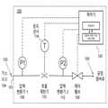
도 1은 본 발명의 일 실시예에 따른 가스 흐름 제어를 자가 검증하기 위한 가스 흐름 제어 장치의 간략화된 개략도이다.
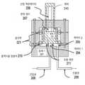
도 2a는 본 발명의 일 실시예에 따른 제어 밸브에 사용되는 고정밀 제어가 가능한 흐름 제한을 위한 장치의 간략화된 개략도로서, 도 2a는 폐쇄 위치에서의 제어 밸브를 나타낸다.
도 2b는 본 발명의 일 실시예에 따른 제어 밸브에 사용되는 고정밀 제어가 가능한 흐름 제한을 위한 장치의 간략화된 개략도로서, 도 2b는 개도량이 "h"로 설계된 개방 위치에서의 제어 밸브를 나타낸다.
도 3은 일 실시예에 따른 흐름 제한기를 간략화한 개략도이다.
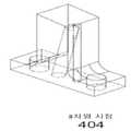
도 4a 및 도 4b는 다른 실시예에 따른 흐름 제한기를 간략화한 개략도이다.
도 5는 일 실시예에 따른 가스의 흐름을 제어하고 검증하기 위한 절차의 흐름도이다.
도 6은 다른 실시예에 따른 가스의 흐름을 제어하고 검증하기 위한 절차의 흐름도이다.
도 7은 본 발명의 일 실시예에 따른 가스 흐름 제어를 자가 검증하기 위한 가스 흐름 제어 장치의 간략화된 개략도이다.BRIEF DESCRIPTION OF THE DRAWINGS The accompanying drawings, which are incorporated in and constitute a part of this specification, illustrate embodiments of the invention and, together with the description, serve to explain and represent the principles of the invention. The drawings are intended to schematically illustrate key features of exemplary embodiments. The drawings are not intended to represent all features of actual embodiments or the relative dimensions of depicted elements, and are not drawn to scale.
1 is a simplified schematic diagram of a gas flow control device for self-verifying gas flow control according to an embodiment of the present invention;
2A is a simplified schematic diagram of a device for high-precision controllable flow restriction used in a control valve according to an embodiment of the present invention, wherein FIG. 2A shows the control valve in a closed position;
FIG. 2B is a simplified schematic diagram of a device for restricting flow capable of high precision control used in a control valve according to an embodiment of the present invention, and FIG. 2B shows the control valve in an open position designed with an opening amount “h”.
3 is a simplified schematic diagram of a flow restrictor according to one embodiment;
4A and 4B are simplified schematic diagrams of a flow restrictor according to another embodiment.
5 is a flow diagram of a procedure for controlling and verifying the flow of gas according to an embodiment.
6 is a flowchart of a procedure for controlling and verifying the flow of gas according to another embodiment.
7 is a simplified schematic diagram of a gas flow control device for self-verifying gas flow control according to an embodiment of the present invention;
본 발명의 측면들에 따르면, 표준 질량 흐름 제어기(mass flow controller; MFC)는 새로운 가스 흐름 제어기(gas flow controller; GFC)로 대체된다. 일반적으로, 표준 MFC에서 측정되는 것은 (가스에 의해 운반되는 열 형태의) 에너지 전달이며, 이는 가스의 질량 흐름과 관련이 있는 것임이 이해되어야 한다. 반대로, 개시된 가스 흐름 제어기에서 측정되고 제어되는 것은 질량 흐름이 아닌 가스 흐름이다. 결과적으로, 개시된 설비를 사용함으로써, 더 나은 가스 흐름의 제어가 이루어진다.According to aspects of the present invention, a standard mass flow controller (MFC) is replaced by a new gas flow controller (GFC). In general, it should be understood that what is measured in a standard MFC is the energy transfer (in the form of heat carried by the gas), which relates to the mass flow of the gas. Conversely, it is the gas flow, not the mass flow, that is measured and controlled in the disclosed gas flow controller. Consequently, better control of gas flow is achieved by using the disclosed equipment.
도 1은 본 발명의 일 실시예에 따른 가스 흐름 제어를 자가 검증하기 위한 가스 흐름 제어 장치(100)의 간략화된 개략도이다. 도 1에서, 가스 소스(gas source)(104)는 가스 흐름을 GFC(100)의 흡입구(101) 안으로 제공한다. 압력 변환기(106)는 흡입구(101)에서 가스 압력을 측정한다. 이어서 가스는 흐름 제한기(110)로 흐르며, 흐름 제한기(110)는 이하에서 도 3, 도 4a 및 도 4b를 참조하여 상세히 설명하도록 한다. 제 2 압력 변환기(112)는 흐름 제한기(110)의 하류측에 제공된다.1 is a simplified schematic diagram of a gas
도 1에서, GFC(100)는 2개의 연속적인 흐름 제한을 구현한다: (1) 상류측 압력, 하류측 압력, 온도 및 흐름 사이의 관계가 잘 특징지어진 흐름 제한기(110), 연이어, (2) 그것의 위치와 흐름 제한 특성들 사이의 매우 정확하고 반복 가능한 매핑(mapping)을 제공하도록 설계되고, 그것의 위치의 제어 및 매우 정확한 측정을 할 수 있는 제어 밸브(108). 이러한 두 흐름 제한들의 연속적인 작동은 가스 흐름을 보다 잘 제어 할 수 있으며 GFC에 의한 자가 모니터링을 가능하게 하는 충분한 매개 변수들을 제공한다.1 ,
본 발명의 다양한 실시예들은, 매우 높은 정밀도로 흐름 제한의 수치를 측정할 수 있고 제어할 수 있는, 제어 가능한 흐름 제한을 갖는 제어 밸브(108)를 사용한다.Various embodiments of the present invention use a
본 발명의 실시예들에서, 이 정도의 정밀도는 다음 특성들을 포함함으로써 얻어진다In embodiments of the present invention, this degree of precision is obtained by including the following characteristics
1. 흐름 제한의 두 대향면들의 단축 모션(uniaxial motion), 여기서 다른 2 개의 축에서의 회전 모션 및/또는 횡 방향(transverse) 모션은 약 1nm 이하로 제한됨1. Uniaxial motion of two opposing faces of flow restriction, where rotational and/or transverse motion in the other two axes is limited to about 1 nm or less
2. 약 1nm의 정밀도로 단축 차원에서의 모션 측정2. Motion measurement in uniaxial dimension with a precision of about 1 nm
3. 약 0.1nm의 분해능(resolution)으로 모션 활성화3. Enable motion with a resolution of about 0.1 nm
이러한 제어 밸브의 예시적인 실시예가 도 2a 및 도 2b에 도시되어 있다. 본 실시예에서, 제어 밸브는 흐름 제한(211)을 형성하는 평면 접촉 영역을 갖는 2개의 인접한 몸체들(201 및 202)로 구성된다. 도 2a는 폐쇄된, 예를 들어, 흐름이 없는 상태를 나타내고, 도 2b는 개방 위치를 나타낸다. 도시된 바와 같이, 몸체(202)는 상부 및 하부 굴곡부들(221)을 통해 몸체(201)에 연결된다. 일 실시예에서, 몸체(201)와 몸체(202)는 원통형이고, 굴곡부들(221)은 몸체(202)로부터 연장된 원형 디스크들이며 몸체 (202)와 같은 블록으로부터 가공 될 수 있거나, 예를 들어, 용접에 의해 몸체(202)에 간단히 부착될 수 있다. 다른 형태도 가능하지만, 원형 형태는 균일하고 균형 잡힌 움직임을 제공한다. 본 실시예에서, 별도의 밀봉부를 제공하는 것이 명백하게 가능할지라도, 굴곡부(221)의 하부는 캐비티(cavity)(213)를 밀봉하기 위하여 밀봉부(210)로서도 기능한다. 캐비티(213)는 몸체(201)의 하부와 몸체(202)의 바닥면 및 굴곡부(221)의 하부에 의해 한정되고, 인입관(208)에 결합된 캐비티(204) 및 인출관(209)에 결합된 캐비티(205)를 포함한다. 몸체(202)가 그것의 이완된 위치에 있을 때, 그것은 캐비티들(204 및 205)을 밀폐하여 분리한다. 몸체(202)가 상승된 위치에 있을 때, 그것은 캐비티들(204 및 205) 사이의 제어된 유체 흐름을 허용한다.An exemplary embodiment of such a control valve is shown in FIGS. 2A and 2B . In this embodiment, the control valve consists of two
선형 액추에이터(206)는 레버(240)와 몸체(201)의 상부 사이에 제공되어, 액추에이터(206)가 팽창할 때 몸체(202)를 상승시키기 위해 레버(202)를 들어 올리고, 도 2b에 도시된 바와 같이, 몸체(202)의 굴곡 부분들이 탄성적으로 구부러지게 한다. 상승된 위치에서, 가스가 인출관(209)으로 흘러 들어갈 수 있도록, 흐름 제한 표면을 형성하는 몸체(202)의 바닥면은 몸체(201)의 상보적인 흐름 제한 표면으로부터 거리 "h"만큼 상승되고, 이에 따라, 흐름 제한 밸브(211)를 통해 캐비티(213)로 제어된 유체가 흘러갈 수 있다. 본 실시예에서, 2개의 원통형 굴곡부들은 몸체들(201 및 202) 사이의 상대적인 모션을 1자유도(수직)로 제한하고, 페이지면에서의 서로에 대한 몸체들의 회전을 제한한다. 이는 흐름 제한(211)을 통한 유체 흐름의 고정밀 제어를 가능하게 한다.A
액츄에이터(206)는, 제2 몸체의 변위를 유도하고, 따라서 흐름 제한 수치를 변경하기 위해, 제2 몸체(202)에 작용하는 제1 몸체(201)에 설치된다. 변위 센서(207)는 제1 몸체에 설치되어 제1 몸체에 대한 제2 몸체 (202)의 변위를 측정한다. 또는, 변위 센서는 레버(240) 또는 액추에이터(206)의 변위를 측정할 수 있다. 일 실시예에서, 이것은, 1나노미터 정도의 선형 변위를 측정할 수 있는, 용량성 측정 디바이스 또는 변위 센서를 이용하여 이루어진다.An
폐루프 제어 회로는 센서(207)의 출력 및 액추에이터(206)의 동작으로 형성되어 흐름 제한(211) 수치들, 및 결과적으로 2개의 캐비티들을 결합하는 흐름 컨덕턴스(conductance)의 제어를 달성한다. 관(208 및 209)은 가스 흐름이 하나의 캐비티와 다른 캐비티의 외부로 향하도록 시스템 내에 통합되며, 그러한 모든 흐름이 두 몸체들에 의해 한정된 흐름 제한을 통해 통과해야 한다.A closed loop control circuit is formed with the output of the sensor 207 and the operation of the
도 1에 도시된 바와 같이, 본 실시예의 GFC는 또한 흐름 제한기(110)를 포함한다. 흐름 제한기의 전형적인 실시예들이 도 3, 도 4a 및 도 4b에 도시되어 있다. 도 3에서, 흐름 제한기를 위해 U자형으로 구부러진 튜브가 사용된다. 도 3에 도시 된 바와 같이, 튜브(301)는 볼트 구멍들(303)에 삽입된 볼트들로 흐름 제어 디바이스(도시되지 않음)의 몸체에 고정된 플랜지(302)의 내부에 용접되어, 흐름 제한기의 가스 흐름 경로를, 흐름 제한기의 상류 및 하류 흐름, 및 흐름 제어 디바이스의 몸체에도 고정된 2개의 압력 변환기들(106 및 112)의 가스 흐름 경로에 연결한다. 도 4a 및 도 4b에서, 흐름 제한기 채널(401)은 블록으로 가공되고, 이 블록은 볼트 구멍들(403) 내로 삽입되는 볼트들로 흐름 제어 디바이스에 유사하게 고정된다.1 , the GFC of this embodiment also includes a
흐름을 제어하기에 앞서, 데이터를 기록하기 위한 룩업 테이블 또는 다른 형태(일반적으로 "룩업 테이블"이라고 함)가 흐름 제한기(110)를 통한 흐름, 온도, 하류측 압력, 및 상류측 압력 사이의 관계를 나타내도록 생성된다. 이러한 동일한 정보를 포착하는 다른 방법은 흐름 제한기(110)를 통과하는 흐름, 온도, 흐름 제한기에 걸친 압력 강하 및 상류측 압력 간의 관계를 기술하는 것이다. 흐름 제한기의 온도를 측정하는 온도 센서(114)뿐만 아니라 흐름 제한기(110)의 양단에 있는 압력 센서들 및 이 룩업 테이블로, 흐름 제한기(110)는 흐름 센서로서 사용될 수 있다. 흐름 제한기에는 움직이는 부분이 없기 때문에, 만약에 있다면, 룩업 테이블로부터 가스 유량의 드리프트는 최소화되어야 한다.Prior to controlling the flow, a lookup table or other form for recording data (commonly referred to as a “lookup table”) is created between the flow through the
도 1의 가스 흐름 제어기(100)는 밸브 위치, 압력 변환기 드리프트 등과 같은, 다른 파라미터들 뿐만 아니라 흐름 정밀도에 대한 자가 진단을 수행할 수 있도록 관찰 및 제어가 가능한 충분한 수의 파라미터들을 갖는다. 더욱이, 이러한 자가 진단은 가스 흐름 제어기가 희망하는 유량의 가스를 공정 챔버로 전달하는 동안 발생할 수 있다.The
도 1의 제어기(120)는 흐름 제한 개방의 필요한 양을 결정할 수 있게 하는 값인, 주어진 가스 압력 및 온도에 대해 희망하는 유량을 얻는데 필요한 h를 컴퓨터 판독 가능 저장 매체 내에 저장한다. 요구되는 개방의 결정은 밸브 위치 h, 압력, 및 온 값들의 넓은 범위에 대한 가스 유량을 측정함으로써 미리 결정된 룩업 테이블을 사용하여 수행될 수 있다.The
가스 제어 밸브(108)를 통해 가스의 흐름을 제어 및 검증하기 위한 절차의 일 실시예가 도 5의 흐름도에 도시되며, 이는 다음과 같이 요약될 수 있다:One embodiment of a procedure for controlling and verifying the flow of gas through a
1. 단계 500에서, 유량에 대한 희망하는 설정값이 제어기(120)에 전송된다. 단계 505에서 설정값이 0이면, 처리가 완료된 것으로 가정하고, 단계 510에서 제어기는 밸브를 닫기 위한 신호를 보내고 절차는 단계 515에서 정지한다.1. In
2. 단계 505에서 설정값이 0이 아니면, 절차는 단계 520으로 진행하며, 여기서 제어기는 필요한 제어 밸브 위치를 룩업 테이블로부터 결정하기 위하여, 압력 변환기(P2)(112)에 의해 표시된 측정된 압력과 함께 제어 밸브 (108)에 대한 룩업 테이블을 사용한다.2. If the setpoint in
3. 제어기는 제1 룩업 테이블로부터 결정된 위치를 설정하기 위해 요구되는 구동 신호를 결정한다. 이는 폐루프 제어 시스템을 이용하여 행해지며, 이에 따라, 제어 밸브 내의 위치 센서가 제1 룩업 테이블로부터 결정된 위치가 525로 설정될 때까지 상기 구동 신호가 변경된다.3. The controller determines the drive signal required to establish the determined position from the first lookup table. This is done using a closed loop control system, whereby the drive signal is changed until the position sensor in the control valve sets the position determined from the first lookup table to 525.
4. 제어기는 온도 센서 T(114), 압력변환기 P1(106) 및 P2(112)의 값들을 판독한다. 이 데이터를 사용하여, 제어기는 흐름 제한기(110)에 대한 제2 룩업 테이블로부터 유량을 결정한다.4. The controller reads the values of the temperature sensor T (114), the pressure transducers P1 (106) and P2 (112). Using this data, the controller determines a flow rate from a second lookup table for
5. 단계 535에서, 제어기는 흐름 제한기 제2 룩업 테이블에 의해 결정된 흐름을 제어 밸브 제1 룩업 테이블에 의해 결정된 흐름과 비교한다. 단계 535에서 그 값들이 일치하면, 절차는 단계 505로 되돌아 간다.5. In
6. 단계 535에서 흐름 제한기 제2 룩업 테이블에 의해 결정된 흐름이 제어 밸브 제1 룩업 테이블에 의해 결정된 흐름과 다른 경우, 단계 540에서 제어기는 흐름 제한기 제2 룩업 테이블에 의해 결정된 흐름과 일치하도록 제어 밸브 제1 룩업 테이블을 갱신한다.6. If in
7. 이에 더하여, 단계 540에서의 비교가 흐름 제한기 룩업 테이블에 의해 결정된 흐름과 제어 밸브 룩업 테이블에 의해 결정된 흐름 사이의 차이는 소정의 기설정된 임계값보다 크다는 것을 나타내면, 제어기는 단계 550에서 알람을 전송한다.7. Additionally, if the comparison in
8. 단계들 2 내지 7은 설정값이 0이 아닌 어떠한 값에 있는 동안 일정한 간격으로 반복된다.8. Steps 2 to 7 are repeated at regular intervals while the setpoint is at any non-zero value.
다른 실시예에서, 제어 밸브(108)를 통해 가스 흐름을 제어하고 검증하는 절차가 도 6의 흐름도에 도시되어 있으며, 이는 다음과 같이 요약 될 수 있다:In another embodiment, the procedure for controlling and verifying gas flow through the
1. 단계 600에서 흐름에 대한 희망하는 설정값은 제어기로 보내진다. 단계 605에서 설정값이 0이면, 처리가 완료된 것으로 가정하고, 단계 610에서 제어기는 밸브를 폐쇄하기 위한 신호를 보내며 절차는 정지한다.1. In
2. 단계 605에서 값이 0이 아니라면, 제어기는 온도 센서 T, 압력 변환기들 P1 및 P2의 값들을 판독한다. 흐름 제한기에 대한 제2 룩업 테이블과 함께 이 데이터를 사용하여, 제어기는 단계 615에서 현재의 흐름을 결정하고, 그 후, 설정값 흐름을 달성하기 위해 흐름이 얼마나 많이 변화해야 하는지를 계산할 수 있게 한다.2. If the value is not zero in
3. 단계 620에서, 제어기는 제어 밸브에 대한 제1 룩업 테이블을 사용하고, 단계 615에서 결정된 흐름의 변화를 제공하기 위해 밸브가 얼마나 많이 이동해야 하는지를 결정한다.3. In step 620, the controller uses the first lookup table for the control valve and determines how much the valve must move to provide the change in flow determined in step 615.
4. 제어기는 단계 625에서 요구되는 양을 이동 시키도록 제어 밸브에 명령한다.4. The controller instructs the control valve to move the required amount in step 625.
5. 위 단계 2, 3 및 4는 설정값이 0이 아닌 어떠한 값에 있는 동안 일정한 간격으로 반복된다.5. Steps 2, 3 and 4 above are repeated at regular intervals while the setpoint is at any non-zero value.
6. 때때로, 명령시 또는 설정값의 각 변경시 또는 다른 편리한 스케쥴에서, 흐름의 정확도는 단계 630에서의 결정마다 체크된다. 이는 단계 635에서 흐름 제한기 룩업 테이블에 의해 결정된 흐름을 제어 밸브 룩업 테이블에 의해 결정된 흐름과 비교하는 것에 의해 행해진다. 단계 640에서 이들 2개의 값들이 소정의 기결정된 임계값 이상의 차이가 난다면, 이후 단계 645에서 경고 또는 알람이 전송되어 흐름의 정확성이 검증 될 수 없다는 것을 조작자에게 경고한다.6. Occasionally, on command or on each change of setpoint or on another convenient schedule, the accuracy of the flow is checked for each determination in
본 실시예에서, 단계 5에서 설명된 일정한 간격은 제어 밸브가 요구되는 위치로 이동할 수 있는 시간보다 짧게 선택된다; 결과적으로, 제어기는 희망하는 설정값과 동일한 흐름 제한기에 대한 룩업 테이블에 의해 결정된 흐름을 지속하기 위해 제어 밸브가 궁극적으로 요구되는 위치로 수렴함에 따라 요구되는 제어 밸브의 이동을 지속적으로 갱신한다.In this embodiment, the constant interval described in step 5 is selected to be shorter than the time during which the control valve can move to the required position; Consequently, the controller continuously updates the desired control valve movement as the control valve ultimately converges to the desired position to sustain flow as determined by the lookup table for the flow restrictor equal to the desired setpoint.
또 다른 실시예에서, 요구되는 정확도가 그다지 높지는 않지만 어떤 유형의 유량 검증이 요망된다면, 열 센서는 흐름 제한기 대신에 가스 제어 밸브의 상류측에 배치될 수 있다. 이는 도 7의 도면에 도시되며, 열 센서(701)는 유량의 정확성을 검증하는데 사용된다. 도 7에서, 열 센서(701)에 의해 측정된 2개의 가열 요소들 사이의 온도차는 가스의 질량유량을 나타낸다. GFC(108)의 상류측. 이 질량유량 데이터는, GFC의 룩업 테이블과 함께, GFC를 통과하는 실제 흐름을 검증하고 모든 드리프트를 보정하는데 사용된다. "배경기술" 단락에서 설명한 바와 같이, 열 센서(701)의 부정확성은 흐름 제한기에서 보다 더 클 수 있다; 그러나 유량의 검증은, 제어 밸브가 GFC(108)의 드리프트(drift)를 검증하는 데 사용될 수 있는 데이터를 제공하기 때문에, 제어 밸브가 제대로 작동하지 않는 경우에 가치를 제공할 것이다. 종래 기술에서 열 센서의 출력은 MFC를 통한 흐름의 표시이기 때문에, 도 7에서 열 센서(701)의 사용은 종래 기술의 MFC에서 그것의 사용과 다르다. 반대로, 도 7의 실시예에서, 열 센서의 출력은 GFC의 상류측 흐름의 표시인 반면, GFC를 통한 흐름은 룩업 테이블을 통해 결정되고 열 센서(701)의 출력에 의해 검증된다. In another embodiment, if the required accuracy is not very high but some type of flow verification is desired, the thermal sensor may be placed upstream of the gas control valve instead of the flow restrictor. This is illustrated in the diagram of FIG. 7 , where a
Claims (12)
Translated fromKorean상기 제어 밸브의 상류측 압력, 상기 제어 밸브의 측정된 위치, 및 유량을 연관시킨 룩업 테이블을 생성하는 단계;
상기 제어 밸브의 상류측 압력 및 상기 룩업 테이블로부터 결정된 위치를 얻기 위해 필요한 구동 신호에 기초하여, 상기 제어 밸브를 통과하는 유량을 설정하는 단계;
상기 제어 밸브의 상류측에 있는 압력 변환기에 의해 압력을 측정하면서 원하는 유량을 제공하기 위해 상기 제어 밸브를 상기 결정된 위치에서 계속해서 지속시키는 단계;
상기 압력 변환기의 상류측에 위치한 유량 센서를 통해 상기 유량을 결정하는 단계- 상기 유량 센서는 흐름 제한기이되, 상기 흐름 제한기는 상기 흐름 제한기의 상류측 및 하류측 압력의 측정값들 및 상기 흐름 제한기의 온도에 기초하여 유량을 결정하는 제2 룩업 테이블을 가짐 -;
상기 룩업 테이블로부터의 상기 원하는 유량과 상기 유량 센서에 의해 결정된 유량 사이의 차이를 계산하는 단계;
상기 차이를 이용하여 상기 룩업 테이블을 갱신하며, 상기 압력을 측정하고 상기 원하는 유량을 달성하기 위해 상기 제어 밸브를 조절하는 것을 계속하는 단계; 및
상기 차이가 미리 결정된 값 이상이면 알람을 전송하는 단계를 포함하는, 방법.
A method of controlling the flow rate of a gas through a control valve, comprising:
generating a lookup table associating the upstream pressure of the control valve, the measured position of the control valve, and the flow rate;
setting a flow rate through the control valve based on an upstream pressure of the control valve and a drive signal necessary to obtain a position determined from the lookup table;
continuing the control valve in the determined position to provide a desired flow rate while measuring pressure by a pressure transducer upstream of the control valve;
determining the flow rate through a flow sensor located upstream of the pressure transducer, the flow sensor being a flow restrictor, wherein the flow restrictor comprises measurements of pressures upstream and downstream of the flow restrictor and the flow having a second lookup table that determines the flow rate based on the temperature of the restrictor;
calculating a difference between the desired flow rate from the lookup table and a flow rate determined by the flow sensor;
updating the lookup table using the difference, continuing to measure the pressure and adjust the control valve to achieve the desired flow rate; and
and sending an alarm if the difference is greater than or equal to a predetermined value.
상기 흐름 제한기는 튜브를 포함하며,
상기 방법은, 상기 흐름 제한기의 상류측 압력을 상기 흐름 제한기의 하류측 압력의 적어도 2배가 되도록 유지하는 단계를 더 포함하는, 방법.
The method of claim 1,
The flow restrictor comprises a tube;
The method further comprises maintaining the pressure upstream of the flow restrictor to be at least twice the pressure downstream of the flow restrictor.
상기 흐름 제한기는 가공된 금속 블록에 형성된 채널을 포함하는, 방법.
The method of claim 1,
wherein the flow restrictor comprises a channel formed in the machined metal block.
a. 상기 제어 밸브의 상류측 압력, 상기 제어 밸브의 측정된 위치, 및 유량을 연관시킨 제1 룩업 테이블을 생성하는 단계;
b. 상기 제어 밸브의 상류측에 위치한 흐름 제한기를 통해 가스의 유량을 결정하는 단계- 상기 가스 유량은 제2 룩업 테이블, 및 상기 흐름 제한기의 상류측 압력, 상기 흐름 제한기의 하류측 압력, 및 상기 흐름 제한기의 온도의 측정값들을 이용하여 결정되고;
c. 원하는 유량을 얻기 위해 제어 밸브 위치에서의 요구되는 변경을 상기 제1 룩업 테이블로부터 결정하는 단계;
d. 제어 밸브 위치의 변경을 구동하는 단계; 및
e. 상기 원하는 유량이 0이 아닌 값을 갖는 동안 상기 단계 b 내지 단계 d를 반복하는 단계를 포함하며,
상기 제1 룩업 테이블로부터 결정된 유량과 상기 제2 룩업 테이블로부터 결정된 유량 사이의 차이를 이용하여 상기 제1 룩업 테이블을 갱신하며, 상기 제1 룩업 테이블을 사용하여 원하는 유량을 달성하도록 상기 제어 밸브가 지속적으로 조절되는, 방법.
A method of controlling the flow rate of a gas through a control valve, comprising:
a. generating a first lookup table associating an upstream pressure of the control valve, a measured position of the control valve, and a flow rate;
b. determining a flow rate of gas through a flow restrictor located upstream of the control valve, wherein the gas flow rate is determined using a second look-up table, the pressure upstream of the flow restrictor, the pressure downstream of the flow restrictor, and determined using measurements of the temperature of the flow restrictor;
c. determining from the first look-up table a required change in control valve position to obtain a desired flow rate;
d. driving a change in control valve position; and
e. repeating steps b to d while the desired flow rate has a non-zero value;
updating the first lookup table using a difference between the flow rate determined from the first lookup table and the flow rate determined from the second lookup table, wherein the control valve is continuously configured to achieve a desired flow rate using the first lookup table regulated by the method.
상기 제어 밸브의 위치 및 상기 제어 밸브의 상류측 가스 압력이 측정되고 상기 제어 밸브를 통한 상기 가스의 유량을 결정하기 위하여 제1 룩업 테이블과 함께 이용되며;
상기 제어 가능한 제어 밸브의 상류측에 위치한 흐름 제한기를 포함하며,
상기 흐름 제한기의 온도 및 상기 흐름 제한기의 상류측 및 하류측의 가스 압력이 측정되고 상기 흐름 제한기를 통한 상기 가스의 유량을 결정하기 위하여 제2 룩업 테이블과 함께 이용되며,
상기 제1 룩업 테이블로부터 결정된 유량과 상기 제2 룩업 테이블로부터 결정된 유량 사이의 차이를 이용하여 상기 제1 룩업 테이블을 갱신하며, 상기 제1 룩업 테이블을 사용하여 원하는 유량을 달성하도록 상기 제어 밸브가 지속적으로 조절되는, 장치
A device for controlling the flow of gas comprising a controllable control valve, comprising:
the position of the control valve and the gas pressure upstream of the control valve are measured and used in conjunction with a first look-up table to determine a flow rate of the gas through the control valve;
a flow restrictor located upstream of the controllable control valve;
the temperature of the flow restrictor and the gas pressures upstream and downstream of the flow restrictor are measured and used in conjunction with a second lookup table to determine the flow rate of the gas through the flow restrictor;
updating the first lookup table using a difference between the flow rate determined from the first lookup table and the flow rate determined from the second lookup table, wherein the control valve is continuously configured to achieve a desired flow rate using the first lookup table controlled by the device
상기 제1 룩업 테이블로부터 결정된 유량과 상기 제2 룩업 테이블로부터 결정된 유량의 비교는 상기 흐름의 정확성을 검증하는데 이용되는, 장치.
6. The method of claim 5,
Comparing the flow rate determined from the first lookup table to the flow rate determined from the second lookup table is used to verify accuracy of the flow.
상기 흐름 제한기는 튜브를 포함하는, 장치.
6. The method of claim 5,
wherein the flow restrictor comprises a tube.
상기 흐름 제한기는 가공된 금속 블록에 형성된 채널을 포함하는, 장치.
6. The method of claim 5,
wherein the flow restrictor comprises a channel formed in a machined metal block.
제어 밸브;
상기 제어 밸브의 상류측에 위치한 흐름 제한기;
상기 흐름 제한기의 상류측에 위치한 제1 압력 변환기;
상기 흐름 제한기의 하류측 및 상기 제어 밸브의 상류측에 위치한 제2 압력 변환기;
상기 흐름 제한기에서 온도를 측정하도록 위치한 온도 센서; 및
프로세서 및 저장 매체를 구비한 제어기를 포함하며,
상기 저장 매체는 상기 제어 밸브의 상류측에서 측정된 제2 압력 변환기의 압력, 상기 제어 밸브의 측정된 위치, 및 상기 제어 밸브를 통한 유량을 연관시킨 제1 룩업 테이블, 및 상기 제1 압력 변환기의 상류측 압력, 상기 제2 압력 변환기의 하류측 압력, 상기 온도 센서의 온도, 및 상기 흐름 제한기를 통한 질량 흐름을 연관시킨 제2 룩업 테이블을 포함하며,
상기 제1 룩업 테이블로부터 결정된 유량과 상기 제2 룩업 테이블로부터 결정된 유량 사이의 차이를 이용하여 상기 제1 룩업 테이블을 갱신하며, 상기 제1 룩업 테이블을 사용하여 원하는 유량을 달성하도록 상기 제어 밸브가 지속적으로 조절되는, 장치.A device for controlling the flow of gas, comprising:
control valve;
a flow restrictor located upstream of the control valve;
a first pressure transducer located upstream of the flow restrictor;
a second pressure transducer located downstream of the flow restrictor and upstream of the control valve;
a temperature sensor positioned to measure a temperature at the flow restrictor; and
a controller having a processor and a storage medium;
The storage medium includes a first lookup table correlating the measured pressure of the second pressure transducer upstream of the control valve, the measured position of the control valve, and the flow rate through the control valve; a second lookup table associating an upstream pressure, a downstream pressure of the second pressure transducer, a temperature of the temperature sensor, and a mass flow through the flow restrictor;
updating the first lookup table using a difference between the flow rate determined from the first lookup table and the flow rate determined from the second lookup table, wherein the control valve is continuously configured to achieve a desired flow rate using the first lookup table controlled by the device.
Applications Claiming Priority (3)
| Application Number | Priority Date | Filing Date | Title |
|---|---|---|---|
| US201562191272P | 2015-07-10 | 2015-07-10 | |
| US62/191,272 | 2015-07-10 | ||
| PCT/US2016/041581WO2017011325A1 (en) | 2015-07-10 | 2016-07-08 | Method and apparatus for gas flow control |
Publications (2)
| Publication Number | Publication Date |
|---|---|
| KR20180030089A KR20180030089A (en) | 2018-03-21 |
| KR102371907B1true KR102371907B1 (en) | 2022-03-08 |
Family
ID=57730874
Family Applications (1)
| Application Number | Title | Priority Date | Filing Date |
|---|---|---|---|
| KR1020187003812AActiveKR102371907B1 (en) | 2015-07-10 | 2016-07-08 | Gas flow control method and device |
Country Status (7)
| Country | Link |
|---|---|
| US (1) | US10401202B2 (en) |
| EP (1) | EP3320408A1 (en) |
| JP (2) | JP6938460B2 (en) |
| KR (1) | KR102371907B1 (en) |
| CN (2) | CN118151685A (en) |
| TW (1) | TWI604291B (en) |
| WO (1) | WO2017011325A1 (en) |
Families Citing this family (23)
| Publication number | Priority date | Publication date | Assignee | Title |
|---|---|---|---|---|
| GB2557670B (en)* | 2016-12-15 | 2020-04-15 | Thermo Fisher Scient Bremen Gmbh | Improved gas flow control |
| US10983538B2 (en) | 2017-02-27 | 2021-04-20 | Flow Devices And Systems Inc. | Systems and methods for flow sensor back pressure adjustment for mass flow controller |
| US11105664B2 (en) | 2017-03-23 | 2021-08-31 | Honeywell International Inc. | Apparatus and method for creating inferential process flow measurements using flow restrictor and upstream and downstream pressure measurements |
| JP6670791B2 (en)* | 2017-03-30 | 2020-03-25 | 東京エレクトロン株式会社 | Method of inspecting flow controller and method of treating object |
| RU2655649C1 (en)* | 2017-07-04 | 2018-05-29 | Акционерное общество "Государственный ракетный центр имени академика В.П. Макеева" | Method of measurement of liquid flow rate and device for its implementation |
| JP7164938B2 (en)* | 2017-07-31 | 2022-11-02 | 株式会社堀場エステック | Flow control device, flow control method, and program for flow control device |
| US11002461B2 (en)* | 2018-02-15 | 2021-05-11 | Johnson Controls Technology Company | System and method for output compensation in flow sensors |
| US10558227B2 (en)* | 2018-02-15 | 2020-02-11 | Johnson Controls Technology Company | System and method for output compensation in flow sensors using pulse width modulation |
| JP7524068B2 (en)* | 2018-04-03 | 2024-07-29 | ラム リサーチ コーポレーション | MEMS Coriolis Gas Flow Controller |
| JP2020021176A (en)* | 2018-07-30 | 2020-02-06 | 株式会社堀場エステック | Flow controller |
| CN113348339A (en)* | 2019-01-25 | 2021-09-03 | 朗姆研究公司 | Differential pressure based flow meter |
| JP2020140711A (en)* | 2019-02-26 | 2020-09-03 | 株式会社フジキン | Mass flow controller, fluid controller, semiconductor manufacturing device, and semiconductor manufacturing method |
| EP3838411A1 (en)* | 2019-12-18 | 2021-06-23 | TECAN Trading AG | Pipetting device and method |
| JP7429464B2 (en)* | 2020-06-29 | 2024-02-08 | 株式会社フジキン | Fluid control device, fluid supply system and fluid supply method |
| WO2022109547A1 (en)* | 2020-11-20 | 2022-05-27 | Mks Instruments, Inc. | Method and apparatus for pulse gas delivery with pressure control |
| CN112696520A (en)* | 2020-12-08 | 2021-04-23 | 江苏中电创新环境科技有限公司 | Control system and method of pneumatic regulating valve |
| CN114623879A (en)* | 2020-12-14 | 2022-06-14 | 宝能汽车集团有限公司 | Gas flow rate detection device and control method thereof |
| CN112786223B (en)* | 2021-01-14 | 2023-10-31 | 中广核研究院有限公司 | Waste heat discharging system and flow stabilizing method |
| KR20250073548A (en)* | 2021-08-13 | 2025-05-27 | 티에스아이 인코포레이티드 | Differential pressure liquid flow controller |
| JP2024055475A (en)* | 2022-10-07 | 2024-04-18 | 愛三工業株式会社 | Valve System |
| US12287655B2 (en)* | 2022-12-16 | 2025-04-29 | Mks Instruments, Inc. | Method and apparatus for mass flow control |
| US20240385632A1 (en)* | 2023-05-19 | 2024-11-21 | Pivotal Systems Corporation | Method and apparatus for controlled splitting of fluid flows |
| US12393209B2 (en) | 2024-01-19 | 2025-08-19 | Mks, Inc. | Methods and apparatus for reporting inlet pressure in mass flow controllers |
Citations (1)
| Publication number | Priority date | Publication date | Assignee | Title |
|---|---|---|---|---|
| JP2004510225A (en)* | 2000-09-20 | 2004-04-02 | ファガシティ コーポレーション | Fluid mass flow controller and operation method thereof |
Family Cites Families (134)
| Publication number | Priority date | Publication date | Assignee | Title |
|---|---|---|---|---|
| JPS5332764U (en)* | 1976-08-27 | 1978-03-22 | ||
| US4114419A (en) | 1977-06-06 | 1978-09-19 | Kimbell Charles L | Method of testing an analyzer to determine the accuracy thereof and a volumetric primary standard apparatus for doing same |
| US4285245A (en) | 1979-12-06 | 1981-08-25 | Precision Machine Products, Inc. | Method and apparatus for measuring and controlling volumetric flow rate of gases in a line |
| JPS6062118A (en) | 1983-09-16 | 1985-04-10 | Canon Inc | Detector for position |
| US4560871A (en) | 1983-12-22 | 1985-12-24 | Marquest Medical Products, Inc. | Actuator for control valves and related systems |
| US4617952A (en) | 1984-07-31 | 1986-10-21 | Yamatake-Honeywell Co. Limited | Switching valve and an electro-pneumatic pressure converter utilizing the same |
| US4695034A (en) | 1984-11-27 | 1987-09-22 | Stec Inc. | Fluid control device |
| JPS62141381A (en) | 1985-12-16 | 1987-06-24 | Hitachi Metals Ltd | Piezoelectric driving type valve |
| US5154206A (en) | 1988-12-01 | 1992-10-13 | United Technologies Corporation | Vibration damper |
| JPH0694909B2 (en) | 1988-12-15 | 1994-11-24 | 工業技術院長 | Fluid control valve using piezoelectric element |
| CA2033181C (en) | 1989-06-14 | 2000-10-24 | Harald T. G. Van Lintel | Two valve micropump with improved outlet |
| DE3919876A1 (en) | 1989-06-19 | 1990-12-20 | Bosch Gmbh Robert | MICRO VALVE |
| DE3926647A1 (en) | 1989-08-11 | 1991-02-14 | Bosch Gmbh Robert | METHOD FOR PRODUCING A MICROVALVE |
| US5238223A (en) | 1989-08-11 | 1993-08-24 | Robert Bosch Gmbh | Method of making a microvalve |
| US5092360A (en) | 1989-11-14 | 1992-03-03 | Hitachi Metals, Ltd. | Flow rated control valve using a high-temperature stacked-type displacement device |
| JPH0434275A (en) | 1990-05-26 | 1992-02-05 | Stec Kk | Normally closed type fluid control valve |
| US5062446A (en) | 1991-01-07 | 1991-11-05 | Sematech, Inc. | Intelligent mass flow controller |
| US5094430A (en) | 1991-03-04 | 1992-03-10 | Stec, Inc. | Control valve |
| US5146941A (en)* | 1991-09-12 | 1992-09-15 | Unitech Development Corp. | High turndown mass flow control system for regulating gas flow to a variable pressure system |
| FR2685752B1 (en) | 1991-12-31 | 1995-03-17 | Gaz De France | METHOD OF CONTINUOUSLY MODULATING A FLOW OF FLUID, USING AN ELECTRICALLY CONTROLLED SEQUENTIAL VALVE. |
| DE4221089A1 (en) | 1992-06-26 | 1994-01-05 | Bosch Gmbh Robert | Microvalve |
| JP2602148Y2 (en)* | 1993-06-22 | 1999-12-27 | 東ソー株式会社 | Orifice flow detection end |
| DE69431994T2 (en) | 1993-10-04 | 2003-10-30 | Res Int Inc | MICRO-MACHINED FLUID TREATMENT DEVICE WITH FILTER AND CONTROL VALVE |
| AU1678595A (en) | 1994-01-14 | 1995-08-01 | Unit Instruments, Inc. | Flow meter |
| US5624409A (en) | 1994-06-10 | 1997-04-29 | Fluidsense Corporation | Variable-pulse dynamic fluid flow controller |
| US5497804A (en) | 1994-06-27 | 1996-03-12 | Caterpillar Inc. | Integral position sensing apparatus for a hydraulic directional valve |
| US5566710A (en) | 1994-09-29 | 1996-10-22 | Dana Corporation | Pre-detent tactile feedback assembly for a fluid control valve |
| US5532922A (en)* | 1994-09-30 | 1996-07-02 | Honeywell Inc. | Non-linear control system for a single input single output process |
| US5593134A (en) | 1995-02-21 | 1997-01-14 | Applied Power Inc. | Magnetically assisted piezo-electric valve actuator |
| JP3291161B2 (en)* | 1995-06-12 | 2002-06-10 | 株式会社フジキン | Pressure type flow controller |
| DE19526897A1 (en) | 1995-07-22 | 1997-01-23 | Bosch Gmbh Robert | Micro-valve operating with high precision |
| US5684245A (en) | 1995-11-17 | 1997-11-04 | Mks Instruments, Inc. | Apparatus for mass flow measurement of a gas |
| JP3260279B2 (en) | 1996-04-03 | 2002-02-25 | 株式会社荏原製作所 | Hydraulic proportional control valve |
| US5730861A (en) | 1996-05-06 | 1998-03-24 | Sterghos; Peter M. | Swimming pool control system |
| US5868159A (en) | 1996-07-12 | 1999-02-09 | Mks Instruments, Inc. | Pressure-based mass flow controller |
| US5865417A (en) | 1996-09-27 | 1999-02-02 | Redwood Microsystems, Inc. | Integrated electrically operable normally closed valve |
| DE19648730C2 (en) | 1996-11-25 | 1998-11-19 | Fraunhofer Ges Forschung | Piezo-electrically operated micro valve |
| DE19735156C1 (en) | 1996-11-25 | 1999-04-29 | Fraunhofer Ges Forschung | Piezo-electrically operated micro valve |
| US5787915A (en) | 1997-01-21 | 1998-08-04 | J. Otto Byers & Associates | Servo positioning system |
| US6062256A (en) | 1997-02-11 | 2000-05-16 | Engineering Measurements Company | Micro mass flow control apparatus and method |
| US5856743A (en) | 1997-03-31 | 1999-01-05 | Honeywell Inc. | Position-determining apparatus |
| JPH1133471A (en) | 1997-07-23 | 1999-02-09 | Tokyo Electron Ltd | Coating device |
| US5942892A (en) | 1997-10-06 | 1999-08-24 | Husco International, Inc. | Method and apparatus for sensing armature position in direct current solenoid actuators |
| US5997280A (en) | 1997-11-07 | 1999-12-07 | Maxon Corporation | Intelligent burner control system |
| US6189858B1 (en) | 1997-12-12 | 2001-02-20 | Smc Kabushiki Kaisha | Piezoelectric valve |
| JP3557087B2 (en) | 1998-02-06 | 2004-08-25 | シーケーディ株式会社 | Mass flow controller flow rate verification system |
| DE19849700C2 (en) | 1998-10-28 | 2001-06-28 | Festo Ag & Co | Micro valve arrangement |
| US6240962B1 (en) | 1998-11-16 | 2001-06-05 | California Institute Of Technology | Parylene micro check valve and fabrication method thereof |
| US6244296B1 (en) | 1999-02-23 | 2001-06-12 | Spx Corporation | Position detection for rotary control valves |
| DE19914372B4 (en) | 1999-03-30 | 2007-05-16 | Pierburg Gmbh | Device for monitoring the valve lift of an electromagnetically driven valve |
| JP3635982B2 (en) | 1999-04-19 | 2005-04-06 | 横河電機株式会社 | Valve positioner and electropneumatic converter |
| JP2001012632A (en) | 1999-04-30 | 2001-01-16 | Tokyo Keiso Co Ltd | Flow control valve and flow control system |
| US6363958B1 (en) | 1999-05-10 | 2002-04-02 | Parker-Hannifin Corporation | Flow control of process gas in semiconductor manufacturing |
| JP4390231B2 (en) | 1999-05-14 | 2009-12-24 | 油研工業株式会社 | Electromagnetic operation device |
| US6119710A (en) | 1999-05-26 | 2000-09-19 | Cyber Instrument Technologies Llc | Method for wide range gas flow system with real time flow measurement and correction |
| US6581623B1 (en) | 1999-07-16 | 2003-06-24 | Advanced Technology Materials, Inc. | Auto-switching gas delivery system utilizing sub-atmospheric pressure gas supply vessels |
| US6138708A (en) | 1999-07-28 | 2000-10-31 | Controls Corporation Of America | Mass flow controller having automatic pressure compensator |
| JP2001141091A (en) | 1999-11-16 | 2001-05-25 | Smc Corp | Flow rate control valve |
| US6460567B1 (en) | 1999-11-24 | 2002-10-08 | Hansen Technologies Corpporation | Sealed motor driven valve |
| US6247493B1 (en) | 2000-03-09 | 2001-06-19 | Richard C. Henderson | Miniature pulsatile flow controller |
| JP2001317646A (en) | 2000-05-08 | 2001-11-16 | Smc Corp | Piezoelectric fluid control valve |
| US6276385B1 (en) | 2000-06-09 | 2001-08-21 | Fisher Controls International, Inc. | Plug and seat positioning system for control applications |
| US6412444B1 (en) | 2000-06-21 | 2002-07-02 | Vaughn P. Esham | Animal anchor and tether system |
| JP2002099330A (en) | 2000-09-22 | 2002-04-05 | Aera Japan Ltd | Flow controller |
| US6688321B2 (en) | 2000-11-06 | 2004-02-10 | David W. Palmer | Method and apparatus for a flow regulator having an integral hinge |
| US6648019B2 (en) | 2000-12-15 | 2003-11-18 | Siemens Automotive Inc. | Air mass flow controller |
| JP2002200597A (en) | 2000-12-28 | 2002-07-16 | Matsushita Electric Works Ltd | Semiconductor micro actuator, and semiconductor micro valve using the same |
| US6782906B2 (en) | 2000-12-28 | 2004-08-31 | Young-Chul Chang | Time based mass flow controller and method for controlling flow rate using it |
| JP3801446B2 (en) | 2001-01-15 | 2006-07-26 | 大日本スクリーン製造株式会社 | Substrate processing equipment |
| US6382226B1 (en) | 2001-04-17 | 2002-05-07 | Fisher Controls International, Inc. | Method for detecting broken valve stem |
| US6761063B2 (en) | 2001-07-02 | 2004-07-13 | Tobi Mengle | True position sensor for diaphragm valves |
| JP3756429B2 (en) | 2001-07-12 | 2006-03-15 | Smc株式会社 | Flow control valve |
| US6627465B2 (en) | 2001-08-30 | 2003-09-30 | Micron Technology, Inc. | System and method for detecting flow in a mass flow controller |
| JP4102564B2 (en)* | 2001-12-28 | 2008-06-18 | 忠弘 大見 | Improved pressure flow controller |
| FR2836536B1 (en) | 2002-02-26 | 2004-05-14 | Cedrat Technologies | PIEZOELECTRIC VALVE |
| US6981518B2 (en) | 2002-03-15 | 2006-01-03 | Cytonome, Inc. | Latching micro-regulator |
| EP1367307B1 (en) | 2002-05-31 | 2004-07-21 | FESTO AG & Co | Piezo-electric valve |
| US6948508B2 (en) | 2002-06-24 | 2005-09-27 | Mks Instruments, Inc. | Apparatus and method for self-calibration of mass flow controller |
| US7809473B2 (en) | 2002-06-24 | 2010-10-05 | Mks Instruments, Inc. | Apparatus and method for pressure fluctuation insensitive mass flow control |
| US7136767B2 (en) | 2002-06-24 | 2006-11-14 | Mks Instruments, Inc. | Apparatus and method for calibration of mass flow controller |
| KR20050067388A (en)* | 2002-08-28 | 2005-07-01 | 호리바 스텍, 인크. | Higher accuracy pressure based flow controller |
| US7559926B1 (en) | 2003-01-13 | 2009-07-14 | Advanced Neuromodulation Systems, Inc. | Actuation system and method for an implantable infusion pump |
| US7089134B2 (en) | 2003-01-17 | 2006-08-08 | Applied Materials, Inc. | Method and apparatus for analyzing gas flow in a gas panel |
| DE10314386A1 (en) | 2003-03-28 | 2004-10-07 | Abb Research Ltd. | Flow regulator for fluids flowing in channels within microtechnology components, has an adjustable flow resistance that is controlled by a regulation unit based on the output of a flow sensor |
| JP4204400B2 (en)* | 2003-07-03 | 2009-01-07 | 忠弘 大見 | Differential pressure type flow meter and differential pressure type flow control device |
| DE502004000445D1 (en) | 2004-02-11 | 2006-05-24 | Festo Ag & Co | piezo valve |
| US7790325B2 (en) | 2004-03-31 | 2010-09-07 | Canon Kabushiki Kaisha | Valve having valve element displaced by at least one of a movement of a diaphragm and a movement of an actuator, and fuel cell using the valve |
| US7882852B2 (en) | 2004-05-04 | 2011-02-08 | Woodward Hrt, Inc. | Direct drive servovalve device with redundant position sensing and methods for making the same |
| ES2245239B1 (en) | 2004-06-03 | 2007-03-01 | Consejo Sup. Investig. Cientificas | SERVOPOSITIONER FOR MICRORREGULATION VALVE. |
| JP4086057B2 (en) | 2004-06-21 | 2008-05-14 | 日立金属株式会社 | Mass flow control device and verification method thereof |
| CN100483286C (en) | 2004-06-21 | 2009-04-29 | 日立金属株式会社 | Flow controller and its regulation method |
| JP2008089607A (en) | 2004-06-21 | 2008-04-17 | Hitachi Metals Ltd | Mass flow controller and its regulation method |
| US20060006484A1 (en) | 2004-07-06 | 2006-01-12 | Dilan Seneviratne | Functional material for micro-mechanical systems |
| WO2006014508A2 (en) | 2004-07-07 | 2006-02-09 | Parker Hannifin Corporation | Flow control apparatus and method with internally isothermal control volume for flow verification |
| US7412986B2 (en) | 2004-07-09 | 2008-08-19 | Celerity, Inc. | Method and system for flow measurement and validation of a mass flow controller |
| JP4977947B2 (en) | 2004-07-16 | 2012-07-18 | 日産自動車株式会社 | Fuel cell system |
| KR101299523B1 (en) | 2005-02-07 | 2013-08-23 | 보그워너 인코포레이티드 | Exhaust throttle-egr valve module for a diesel engine |
| US7992395B2 (en) | 2006-01-17 | 2011-08-09 | Hussmann Corporation | Expansion valve with piezo material |
| US7283894B2 (en) | 2006-02-10 | 2007-10-16 | Dresser, Inc. | System and method for fluid regulation |
| US7409871B2 (en)* | 2006-03-16 | 2008-08-12 | Celerity, Inc. | Mass flow meter or controller with inclination sensor |
| US8219329B2 (en)* | 2006-05-26 | 2012-07-10 | Horiba Stec, Co., Ltd. | Thermal type mass flow meter, and thermal type mass flow control device |
| US7631492B2 (en) | 2006-12-20 | 2009-12-15 | Suresh Arvind S | System and method for inhibiting uncontrolled regeneration of a particulate filter for an internal combustion engine |
| DE102007004595A1 (en) | 2007-01-30 | 2008-08-07 | Samson Ag | Method for transferring electrical position information of e.g. valve unit, involves combining binary signal status and position information to form position signal so that status and information is selectively called from position signal |
| JP4933936B2 (en) | 2007-03-30 | 2012-05-16 | 株式会社フジキン | Piezoelectric drive valve |
| JP2011510404A (en) | 2008-01-18 | 2011-03-31 | ピヴォタル システムズ コーポレーション | Method for determining gas flow rate, method for determining the operation of a gas flow controller, method for determining a partial capacity of a gas flow control system, and gas transport system |
| US8205629B2 (en) | 2008-04-25 | 2012-06-26 | Applied Materials, Inc. | Real time lead-line characterization for MFC flow verification |
| CN101299767A (en)* | 2008-05-07 | 2008-11-05 | 珠海欧比特控制工程股份有限公司 | System and method for calculating flow |
| JP5177864B2 (en) | 2008-06-04 | 2013-04-10 | 株式会社フジキン | Automatic pressure regulator for thermal mass flow regulator |
| US7826986B2 (en)* | 2008-09-26 | 2010-11-02 | Advanced Energy Industries, Inc. | Method and system for operating a mass flow controller |
| JP5395451B2 (en)* | 2009-02-10 | 2014-01-22 | サーパス工業株式会社 | Flow controller |
| US8844901B2 (en) | 2009-03-27 | 2014-09-30 | Horiba Stec, Co., Ltd. | Flow control valve |
| US8160833B2 (en)* | 2009-07-14 | 2012-04-17 | Hitachi Metals, Ltd | Thermal mass flow sensor with improved response across fluid types |
| TWI435196B (en) | 2009-10-15 | 2014-04-21 | Pivotal Systems Corp | Method and apparatus for gas flow control |
| CN101696742B (en) | 2009-10-21 | 2010-12-08 | 潘兆铿 | Multi-channel stepped electric gas control valve |
| US8271210B2 (en) | 2009-12-09 | 2012-09-18 | Pivotal Systems Corporation | Method and apparatus for enhancing in-situ gas flow measurement performance |
| US8271211B2 (en)* | 2009-12-09 | 2012-09-18 | Pivotal Systems Corporation | Method and apparatus for enhancing in-situ gas flow measurement performance |
| US8265888B2 (en) | 2009-12-09 | 2012-09-11 | Pivotal Systems Corporation | Method and apparatus for enhancing in-situ gas flow measurement performance |
| US8504311B2 (en)* | 2010-04-09 | 2013-08-06 | Hitachi Metals, Ltd. | Method and mass flow controller for enhanced operating range |
| US9400004B2 (en)* | 2010-11-29 | 2016-07-26 | Pivotal Systems Corporation | Transient measurements of mass flow controllers |
| US20120197446A1 (en)* | 2010-12-01 | 2012-08-02 | Glaudel Stephen P | Advanced feed-forward valve-control for a mass flow controller |
| JP5809012B2 (en)* | 2011-10-14 | 2015-11-10 | 株式会社堀場エステック | Diagnosis device and diagnostic program used in a flow control device, a flow measurement mechanism, or a flow control device including the flow measurement mechanism |
| US9557744B2 (en)* | 2012-01-20 | 2017-01-31 | Mks Instruments, Inc. | System for and method of monitoring flow through mass flow controllers in real time |
| JP5833475B2 (en)* | 2012-03-02 | 2015-12-16 | アズビル株式会社 | Gas flow measuring device and flow control valve |
| JP5887188B2 (en)* | 2012-04-12 | 2016-03-16 | 株式会社堀場エステック | Fluid control equipment |
| JP5868796B2 (en)* | 2012-07-03 | 2016-02-24 | 株式会社堀場エステック | PRESSURE CONTROL DEVICE, FLOW CONTROL DEVICE, PRESSURE CONTROL DEVICE PROGRAM, FLOW CONTROL DEVICE PROGRAM |
| CN102841178B (en)* | 2012-08-24 | 2014-11-19 | 东莞市升微机电设备科技有限公司 | VOC (Volatile organic compound) release cabin with air inlet flow compensation control system and control method |
| WO2014040002A2 (en)* | 2012-09-10 | 2014-03-13 | Mudd Daniel T | Pressure based mass flow controller |
| JP6002029B2 (en)* | 2012-12-26 | 2016-10-05 | アズビル株式会社 | Flow rate calculation device and flow rate control device |
| US9488516B2 (en)* | 2013-03-14 | 2016-11-08 | Hitachi Metals, Ltd. | On-tool mass flow controller diagnostic systems and methods |
| US9454158B2 (en)* | 2013-03-15 | 2016-09-27 | Bhushan Somani | Real time diagnostics for flow controller systems and methods |
| JP6264152B2 (en)* | 2014-03-31 | 2018-01-24 | 日立金属株式会社 | Mass flow meter and mass flow controller using the mass flow meter |
| JP2016192039A (en)* | 2015-03-31 | 2016-11-10 | アズビル株式会社 | Flow control valve |
| JP6512959B2 (en)* | 2015-06-19 | 2019-05-15 | 東京エレクトロン株式会社 | Gas supply system, gas supply control method, and gas replacement method |
| WO2017040100A1 (en)* | 2015-08-31 | 2017-03-09 | Mks Instruments, Inc. | Method and apparatus for pressure-based flow measurement in non-critical flow conditions |
- 2016
- 2016-07-08KRKR1020187003812Apatent/KR102371907B1/enactiveActive
- 2016-07-08USUS15/206,180patent/US10401202B2/enactiveActive
- 2016-07-08JPJP2018500675Apatent/JP6938460B2/enactiveActive
- 2016-07-08CNCN202311244365.4Apatent/CN118151685A/enactivePending
- 2016-07-08WOPCT/US2016/041581patent/WO2017011325A1/ennot_activeCeased
- 2016-07-08EPEP16824948.0Apatent/EP3320408A1/ennot_activeWithdrawn
- 2016-07-08CNCN201680048194.XApatent/CN107924199A/enactivePending
- 2016-07-11TWTW105121691Apatent/TWI604291B/enactive
- 2021
- 2021-07-01JPJP2021109827Apatent/JP7291176B2/enactiveActive
Patent Citations (1)
| Publication number | Priority date | Publication date | Assignee | Title |
|---|---|---|---|---|
| JP2004510225A (en)* | 2000-09-20 | 2004-04-02 | ファガシティ コーポレーション | Fluid mass flow controller and operation method thereof |
Also Published As
| Publication number | Publication date |
|---|---|
| CN107924199A (en) | 2018-04-17 |
| KR20180030089A (en) | 2018-03-21 |
| JP2018520441A (en) | 2018-07-26 |
| TW201702781A (en) | 2017-01-16 |
| JP7291176B2 (en) | 2023-06-14 |
| TWI604291B (en) | 2017-11-01 |
| EP3320408A1 (en) | 2018-05-16 |
| US10401202B2 (en) | 2019-09-03 |
| CN118151685A (en) | 2024-06-07 |
| WO2017011325A1 (en) | 2017-01-19 |
| JP2021184257A (en) | 2021-12-02 |
| US20170010625A1 (en) | 2017-01-12 |
| JP6938460B2 (en) | 2021-09-22 |
Similar Documents
| Publication | Publication Date | Title |
|---|---|---|
| KR102371907B1 (en) | Gas flow control method and device | |
| US9983595B2 (en) | Method and apparatus for gas flow control | |
| JP4788920B2 (en) | Mass flow control device, verification method thereof, and semiconductor manufacturing device | |
| US9739655B2 (en) | System and method for using a rate of decay measurement for real time measurement and correction of zero offset and zero drift of a mass flow controller or mass flow meter | |
| CN101636641B (en) | Controller gain scheduling for mass flow controllers | |
| JP6691167B2 (en) | Mass flow controller and method for controlling fluid flow rate | |
| US10437264B2 (en) | System and method for improving the accuracy of a rate of decay measurement for real time correction in a mass flow controller or mass flow meter by using a thermal model to minimize thermally induced error in the rod measurement | |
| CN111902786A (en) | Mass flow controller with absolute and differential pressure transducers | |
| WO2025038383A1 (en) | Method and apparatus for automatic self calibration of mass flow controller | |
| US20170336810A1 (en) | Wireless flow restrictor of a flowmeter | |
| JP7249030B2 (en) | Volume measuring method in flow measuring device and flow measuring device |
Legal Events
| Date | Code | Title | Description |
|---|---|---|---|
| PA0105 | International application | Patent event date:20180207 Patent event code:PA01051R01D Comment text:International Patent Application | |
| PG1501 | Laying open of application | ||
| PA0201 | Request for examination | Patent event code:PA02012R01D Patent event date:20210422 Comment text:Request for Examination of Application | |
| PA0302 | Request for accelerated examination | Patent event date:20210422 Patent event code:PA03022R01D Comment text:Request for Accelerated Examination | |
| E902 | Notification of reason for refusal | ||
| PE0902 | Notice of grounds for rejection | Comment text:Notification of reason for refusal Patent event date:20210820 Patent event code:PE09021S01D | |
| E701 | Decision to grant or registration of patent right | ||
| PE0701 | Decision of registration | Patent event code:PE07011S01D Comment text:Decision to Grant Registration Patent event date:20211202 | |
| GRNT | Written decision to grant | ||
| PR0701 | Registration of establishment | Comment text:Registration of Establishment Patent event date:20220303 Patent event code:PR07011E01D | |
| PR1002 | Payment of registration fee | Payment date:20220304 End annual number:3 Start annual number:1 | |
| PG1601 | Publication of registration | ||
| PR1001 | Payment of annual fee | Payment date:20250106 Start annual number:4 End annual number:4 |