KR102371015B1 - Method for controlling hybrid electric vehicle - Google Patents
Method for controlling hybrid electric vehicleDownload PDFInfo
- Publication number
- KR102371015B1 KR102371015B1KR1020170129870AKR20170129870AKR102371015B1KR 102371015 B1KR102371015 B1KR 102371015B1KR 1020170129870 AKR1020170129870 AKR 1020170129870AKR 20170129870 AKR20170129870 AKR 20170129870AKR 102371015 B1KR102371015 B1KR 102371015B1
- Authority
- KR
- South Korea
- Prior art keywords
- operating point
- engine
- power
- driver
- motor
- Prior art date
- Legal status (The legal status is an assumption and is not a legal conclusion. Google has not performed a legal analysis and makes no representation as to the accuracy of the status listed.)
- Active
Links
- 238000000034methodMethods0.000titleclaimsabstractdescription79
- 238000010586diagramMethods0.000claimsabstractdescription21
- 230000005540biological transmissionEffects0.000claimsdescription19
- 230000001172regenerating effectEffects0.000claimsdescription11
- 239000000446fuelSubstances0.000abstractdescription24
- 230000008569processEffects0.000abstractdescription17
- 238000007599dischargingMethods0.000abstractdescription6
- 230000008929regenerationEffects0.000description15
- 238000011069regeneration methodMethods0.000description15
- 230000008859changeEffects0.000description6
- 235000009508confectioneryNutrition0.000description6
- 230000000694effectsEffects0.000description3
- 230000006872improvementEffects0.000description3
- 230000007246mechanismEffects0.000description3
- 230000007613environmental effectEffects0.000description2
- 230000007704transitionEffects0.000description2
- 230000001133accelerationEffects0.000description1
- 230000008901benefitEffects0.000description1
- 238000004364calculation methodMethods0.000description1
- 238000002485combustion reactionMethods0.000description1
- 239000002803fossil fuelSubstances0.000description1
- 230000004048modificationEffects0.000description1
- 238000012986modificationMethods0.000description1
- 239000007858starting materialSubstances0.000description1
Images


Classifications
- B—PERFORMING OPERATIONS; TRANSPORTING
- B60—VEHICLES IN GENERAL
- B60W—CONJOINT CONTROL OF VEHICLE SUB-UNITS OF DIFFERENT TYPE OR DIFFERENT FUNCTION; CONTROL SYSTEMS SPECIALLY ADAPTED FOR HYBRID VEHICLES; ROAD VEHICLE DRIVE CONTROL SYSTEMS FOR PURPOSES NOT RELATED TO THE CONTROL OF A PARTICULAR SUB-UNIT
- B60W10/00—Conjoint control of vehicle sub-units of different type or different function
- B60W10/04—Conjoint control of vehicle sub-units of different type or different function including control of propulsion units
- B60W10/06—Conjoint control of vehicle sub-units of different type or different function including control of propulsion units including control of combustion engines
- B—PERFORMING OPERATIONS; TRANSPORTING
- B60—VEHICLES IN GENERAL
- B60W—CONJOINT CONTROL OF VEHICLE SUB-UNITS OF DIFFERENT TYPE OR DIFFERENT FUNCTION; CONTROL SYSTEMS SPECIALLY ADAPTED FOR HYBRID VEHICLES; ROAD VEHICLE DRIVE CONTROL SYSTEMS FOR PURPOSES NOT RELATED TO THE CONTROL OF A PARTICULAR SUB-UNIT
- B60W10/00—Conjoint control of vehicle sub-units of different type or different function
- B60W10/04—Conjoint control of vehicle sub-units of different type or different function including control of propulsion units
- B60W10/08—Conjoint control of vehicle sub-units of different type or different function including control of propulsion units including control of electric propulsion units, e.g. motors or generators
- B—PERFORMING OPERATIONS; TRANSPORTING
- B60—VEHICLES IN GENERAL
- B60W—CONJOINT CONTROL OF VEHICLE SUB-UNITS OF DIFFERENT TYPE OR DIFFERENT FUNCTION; CONTROL SYSTEMS SPECIALLY ADAPTED FOR HYBRID VEHICLES; ROAD VEHICLE DRIVE CONTROL SYSTEMS FOR PURPOSES NOT RELATED TO THE CONTROL OF A PARTICULAR SUB-UNIT
- B60W10/00—Conjoint control of vehicle sub-units of different type or different function
- B60W10/24—Conjoint control of vehicle sub-units of different type or different function including control of energy storage means
- B60W10/26—Conjoint control of vehicle sub-units of different type or different function including control of energy storage means for electrical energy, e.g. batteries or capacitors
- B—PERFORMING OPERATIONS; TRANSPORTING
- B60—VEHICLES IN GENERAL
- B60W—CONJOINT CONTROL OF VEHICLE SUB-UNITS OF DIFFERENT TYPE OR DIFFERENT FUNCTION; CONTROL SYSTEMS SPECIALLY ADAPTED FOR HYBRID VEHICLES; ROAD VEHICLE DRIVE CONTROL SYSTEMS FOR PURPOSES NOT RELATED TO THE CONTROL OF A PARTICULAR SUB-UNIT
- B60W20/00—Control systems specially adapted for hybrid vehicles
- B60W20/10—Controlling the power contribution of each of the prime movers to meet required power demand
- B—PERFORMING OPERATIONS; TRANSPORTING
- B60—VEHICLES IN GENERAL
- B60W—CONJOINT CONTROL OF VEHICLE SUB-UNITS OF DIFFERENT TYPE OR DIFFERENT FUNCTION; CONTROL SYSTEMS SPECIALLY ADAPTED FOR HYBRID VEHICLES; ROAD VEHICLE DRIVE CONTROL SYSTEMS FOR PURPOSES NOT RELATED TO THE CONTROL OF A PARTICULAR SUB-UNIT
- B60W50/00—Details of control systems for road vehicle drive control not related to the control of a particular sub-unit, e.g. process diagnostic or vehicle driver interfaces
- B60W50/08—Interaction between the driver and the control system
- B60W50/10—Interpretation of driver requests or demands
- B—PERFORMING OPERATIONS; TRANSPORTING
- B60—VEHICLES IN GENERAL
- B60W—CONJOINT CONTROL OF VEHICLE SUB-UNITS OF DIFFERENT TYPE OR DIFFERENT FUNCTION; CONTROL SYSTEMS SPECIALLY ADAPTED FOR HYBRID VEHICLES; ROAD VEHICLE DRIVE CONTROL SYSTEMS FOR PURPOSES NOT RELATED TO THE CONTROL OF A PARTICULAR SUB-UNIT
- B60W2510/00—Input parameters relating to a particular sub-units
- B60W2510/06—Combustion engines, Gas turbines
- B60W2510/0638—Engine speed
- B—PERFORMING OPERATIONS; TRANSPORTING
- B60—VEHICLES IN GENERAL
- B60W—CONJOINT CONTROL OF VEHICLE SUB-UNITS OF DIFFERENT TYPE OR DIFFERENT FUNCTION; CONTROL SYSTEMS SPECIALLY ADAPTED FOR HYBRID VEHICLES; ROAD VEHICLE DRIVE CONTROL SYSTEMS FOR PURPOSES NOT RELATED TO THE CONTROL OF A PARTICULAR SUB-UNIT
- B60W2530/00—Input parameters relating to vehicle conditions or values, not covered by groups B60W2510/00 or B60W2520/00
- B60W2530/13—Mileage
- B—PERFORMING OPERATIONS; TRANSPORTING
- B60—VEHICLES IN GENERAL
- B60Y—INDEXING SCHEME RELATING TO ASPECTS CROSS-CUTTING VEHICLE TECHNOLOGY
- B60Y2200/00—Type of vehicle
- B60Y2200/90—Vehicles comprising electric prime movers
- B60Y2200/92—Hybrid vehicles
- Y—GENERAL TAGGING OF NEW TECHNOLOGICAL DEVELOPMENTS; GENERAL TAGGING OF CROSS-SECTIONAL TECHNOLOGIES SPANNING OVER SEVERAL SECTIONS OF THE IPC; TECHNICAL SUBJECTS COVERED BY FORMER USPC CROSS-REFERENCE ART COLLECTIONS [XRACs] AND DIGESTS
- Y02—TECHNOLOGIES OR APPLICATIONS FOR MITIGATION OR ADAPTATION AGAINST CLIMATE CHANGE
- Y02T—CLIMATE CHANGE MITIGATION TECHNOLOGIES RELATED TO TRANSPORTATION
- Y02T10/00—Road transport of goods or passengers
- Y02T10/10—Internal combustion engine [ICE] based vehicles
- Y02T10/40—Engine management systems
- Y—GENERAL TAGGING OF NEW TECHNOLOGICAL DEVELOPMENTS; GENERAL TAGGING OF CROSS-SECTIONAL TECHNOLOGIES SPANNING OVER SEVERAL SECTIONS OF THE IPC; TECHNICAL SUBJECTS COVERED BY FORMER USPC CROSS-REFERENCE ART COLLECTIONS [XRACs] AND DIGESTS
- Y02—TECHNOLOGIES OR APPLICATIONS FOR MITIGATION OR ADAPTATION AGAINST CLIMATE CHANGE
- Y02T—CLIMATE CHANGE MITIGATION TECHNOLOGIES RELATED TO TRANSPORTATION
- Y02T10/00—Road transport of goods or passengers
- Y02T10/60—Other road transportation technologies with climate change mitigation effect
- Y02T10/62—Hybrid vehicles
Landscapes
- Engineering & Computer Science (AREA)
- Chemical & Material Sciences (AREA)
- Combustion & Propulsion (AREA)
- Transportation (AREA)
- Mechanical Engineering (AREA)
- Automation & Control Theory (AREA)
- Human Computer Interaction (AREA)
- Electric Propulsion And Braking For Vehicles (AREA)
- Hybrid Electric Vehicles (AREA)
Abstract
Translated fromKoreanDescription
Translated fromKorean본 발명은 하이브리드 차량의 제어 방법에 관한 것으로서, 더욱 상세하게는 모터에 의한 배터리 충, 방전 과정에서 에너지 손실을 줄일 수 있는 보다 효율적인 운전점에서 엔진을 작동시킬 수 있고, 이를 통해 연료 소모 효율 및 차량 연비의 향상을 도모할 수 있는 하이브리드 차량의 제어 방법에 관한 것이다.
The present invention relates to a control method of a hybrid vehicle, and more particularly, it is possible to operate an engine at a more efficient operating point that can reduce energy loss in the process of charging and discharging a battery by a motor, thereby improving fuel consumption efficiency and vehicle The present invention relates to a control method of a hybrid vehicle capable of improving fuel efficiency.
하이브리드 차량은 서로 다른 두 종류 이상의 구동원을 사용하는 차량을 의미하나, 대부분의 경우 연료(가솔린 등 화석연료)를 연소시켜 회전력을 얻는 엔진과 배터리 전력으로 회전력을 얻는 모터에 의해 구동되는 차량을 의미한다.A hybrid vehicle refers to a vehicle using two or more different driving sources, but in most cases, it refers to a vehicle driven by an engine that burns fuel (fossil fuel, such as gasoline) to obtain rotational power and a motor that obtains rotational power using battery power. .
하이브리드 차량은 엔진과 모터로 구성되는 두 종류의 구동원으로 주행하는 과정에서 엔진과 모터를 어떻게 조화롭게 작동시키느냐에 따라 최적의 토크를 출력할 수 있음은 물론 차량 연비를 극대화할 수 있다.A hybrid vehicle can output optimum torque and maximize vehicle fuel efficiency depending on how the engine and motor are harmoniously operated in the process of driving with two types of driving sources consisting of an engine and a motor.
이러한 하이브리드 차량은 엔진과 모터를 사용하여 다양한 구조로 구동계를 구성할 수 있는데, 엔진과 모터를 엔진 클러치를 통해 연결하고 모터의 출력 측에 변속기를 연결한 TMED(Transmission Mounted Electric Device) 방식과, 모터가 엔진의 크랭크 축에 직접 연결되고 플라이 휠을 통해 변속기가 연결되는 FMED(Flywheel Mounted Electric Device) 방식이 있다.Such a hybrid vehicle can configure a drive system in various structures using an engine and a motor. The TMED (Transmission Mounted Electric Device) method in which the engine and the motor are connected through the engine clutch and the transmission is connected to the output side of the motor, and the motor There is a Flywheel Mounted Electric Device (FMED) method in which the engine is directly connected to the crankshaft of the engine and the transmission is connected through a flywheel.
또한, 하이브리드 차량은 시스템 효율을 높이기 위해 최대 시스템 효율을 나타내는 최적 운전 곡선(Optimal Operating Line, OOL)을 추종하도록 엔진 운전점이 선택되고, 최종 선택된 엔진 운전점에 해당하는 토크(Nm)와 속도(rpm)를 낼 수 있도록 엔진을 구동 및 제어한다.In addition, in the hybrid vehicle, an engine operating point is selected to follow an Optimal Operating Line (OOL) indicating maximum system efficiency in order to increase system efficiency, and the torque (Nm) and speed (rpm) corresponding to the finally selected engine operating point are selected. ) to drive and control the engine.
특히, 최적 운전 곡선(OOL)을 따르는 엔진 운전점 중 스윗 스팟(Sweet Spot, SS)에 해당하는 운전점, 즉 기준 운전점에서 크게 벗어나지 않는 운전점(기준 운전점 또는 기준 운전점 주변의 운전점)을 최종 선택하여 엔진을 작동시킴으로써 엔진의 열 효율을 최대한 높이게 된다.In particular, an operating point that corresponds to a sweet spot (SS) among engine operating points that follow the optimal operating curve (OOL), that is, an operating point that does not deviate significantly from the reference operating point (the reference operating point or an operating point around the reference operating point) ) is finally selected to operate the engine, thereby maximizing the thermal efficiency of the engine.
여기서, 기준 운전점(SS)은 등고선 형태의 연료 소모율 정보를 나타내는 BSFC(Brake Specific Fuel Consumption) 맵 상에서 최적 운전점이 되는 것으로서, BSFC 맵 상의 BSFC 값(연료 소모량)이 최소가 되는 운전점이 되며, BSFC 값과 엔진 효율은 반비례 관계가 있으므로, 기준 운전점은 하이브리드 차량에서 엔진 효율의 최대점이 된다.Here, the reference operating point (SS) is an optimal operating point on a BSFC (Brake Specific Fuel Consumption) map representing fuel consumption rate information in the form of a contour line, and is an operating point at which the BSFC value (fuel consumption) on the BSFC map is minimized, and the BSFC Since the value and engine efficiency are in inverse proportion to each other, the reference operating point becomes the maximum point of engine efficiency in the hybrid vehicle.
또한, 하이브리드 차량에서 제어기는 가속페달 조작값(APS 값), 브레이크 페달 조작값(BPS 값) 등의 차량 운전 정보와, 기어단, 차속, 엔진 속도(RPM), 배터리 충전상태(state of charge, SOC) 등의 차량 상태 정보, 그리고 도로 등의 환경변수를 실시간으로 수집하고, 수집된 정보에 기초하여 운전자 요구 토크를 결정한다.In addition, in the hybrid vehicle, the controller includes vehicle driving information such as accelerator pedal operation value (APS value) and brake pedal operation value (BPS value), gear stage, vehicle speed, engine speed (RPM), battery state of charge, Vehicle state information such as SOC) and environmental variables such as roads are collected in real time, and the driver's demand torque is determined based on the collected information.
이와 같이 운전자 요구 토크가 결정되면, 운전자 요구 토크(운전자 요구 파워)를 만족하는 차량 구동 토크를 얻기 위하여, 엔진을 상기와 같이 최종 선택된 운전점으로 작동시키면서, 운전자 요구 토크가 엔진 토크보다 큰 경우 모터 토크(모터 구동토크)로 보상하여 운전자 요구 토크를 충족시킨다(방전, 모터 어시스트).When the driver's demand torque is determined in this way, in order to obtain a vehicle driving torque that satisfies the driver's demanded torque (driver's demanded power), the engine is operated at the finally selected operating point as described above, and the motor when the driver's demanded torque is greater than the engine torque It compensates with torque (motor driving torque) to satisfy the driver's demand torque (discharge, motor assist).
반면, 운전자 요구 토크가 기준 운전점의 엔진 토크(엔진 토크 기준값)보다 작은 경우 엔진에서 발생한 잉여의 출력만큼 모터를 발전기로 작동시켜 배터리를 충전한다(충전, 모터 회생).On the other hand, when the driver's requested torque is less than the engine torque (engine torque reference value) at the reference operating point, the motor is operated as a generator by the surplus output generated by the engine to charge the battery (charging, motor regeneration).
이는 모터 대비 운전점에 따른 효율 변화가 급격한 엔진의 효율을 극대화하기 위한 전략이다.This is a strategy to maximize the efficiency of the engine, which has a sharp change in efficiency depending on the operating point compared to the motor.
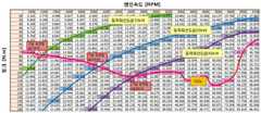
도 1은 하이브리드 차량에서 최적 운전 곡선(OOL)을 따르는 운전점 중 기준 운전점으로 엔진 운전점이 결정될 때 운전자 요구 토크를 충족시키기 위해 모터 회생 및 모터 어시스트가 이루어짐을 보여주고 있다.FIG. 1 shows that in a hybrid vehicle, when an engine operating point is determined as a reference operating point among operating points following an optimal driving curve OOL, motor regeneration and motor assist are performed to satisfy a driver's demand torque.
도 1에서 토크(torque, Nm)와 엔진 속도(engine speed, RPM)에 해당하는 각 수치는 파워(kW) 값을 나타낸다.In FIG. 1 , each numerical value corresponding to torque (Nm) and engine speed (RPM) represents a value of power (kW).
또한, 도 1에는 예로서 파워가 대략 10kW에 근접되는 운전점들을 연결한 10kW 등파워선도("등파워선도@10kW"), 20kW에 근접되는 운전점들을 연결한 20kW 등파워선도("등파워선도@20kW"), 30kW에 근접되는 운전점들을 연결한 30kW 등파워선도("등파워선도@30kW")가 도시되어 있다.In addition, in FIG. 1, as an example, a 10kW isopower diagram (“Isopower diagram @10kW”) connecting operating points with power close to 10kW, and a 20kW isopower diagram connecting operating points close to 20kW (“Equal power”) Diagram @ 20 kW") and a 30 kW isopower diagram (“Implemental power diagram @ 30 kW”) connecting operating points approaching 30 kW are shown.
운전자가 가속페달을 밟게 되면 가속페달 조작값, 즉 APS(Acceleration Position Sensor) 신호값 등에 상응하는 운전자 요구 파워가 결정되는데, 도 1은 운전자 요구 파워가 각각 10kW, 20kW, 30kW일 때 모터 회생 또는 모터 어시스트가 수행됨을 예시하고 있다.When the driver depresses the accelerator pedal, the driver's demand power corresponding to the accelerator pedal operation value, that is, the APS (Acceleration Position Sensor) signal value, etc. is determined. In Fig. 1, when the driver's requested power is 10 kW, 20 kW, and 30 kW, respectively It is exemplified that the assist is being performed.
도시된 바와 같이, 기준 운전점에 해당하는 토크(Nm)와 속도(rpm)를 내도록 엔진이 제어되고, 기준 운전점에서의 운전자 요구 토크와 엔진 토크의 차이가 모터 토크, 즉 모터 구동토크(방전, 모터 어시스트) 또는 모터 회생토크(충전, 모터 회생)에 의해 보상된다.As shown, the engine is controlled to generate torque (Nm) and speed (rpm) corresponding to the reference operating point, and the difference between the driver's requested torque and the engine torque at the reference operating point is the motor torque, that is, the motor driving torque (discharge). , motor assist) or motor regenerative torque (charging, motor regenerative).
한편, 하이브리드 차량이 주행하는 동안 배터리 SOC(state of charge)는 적정의 정상 범위 내에서 관리될 필요가 있다.Meanwhile, while the hybrid vehicle is driving, the battery state of charge (SOC) needs to be managed within an appropriate normal range.
즉, SOC가 정상 범위보다 높을 경우 모터에 의한 에너지 회생 조건을 만족함에도 에너지 회생을 수행하지 못하는 등의 제한(충전 제한)이 있게 되므로, 이를 회피하기 위해서는 모터 어시스트량을 늘리는 방전 지향 주행을 통해 SOC를 떨어뜨리는 것이 유리하다.That is, if the SOC is higher than the normal range, there are limitations (charging restrictions) such as not being able to perform energy regeneration even if the energy regeneration condition by the motor is satisfied. It is advantageous to drop
반면, SOC가 정상 범위보다 낮을 경우 SOC를 정상 범위 이내로 유지하기 위해 모터 회생량 및 배터리 충전량을 늘리는 충전 지향 주행을 통해 SOC를 상승시키는 것이 유리하다.On the other hand, when the SOC is lower than the normal range, it is advantageous to increase the SOC through charge-oriented driving in which the motor regeneration amount and the battery charge amount are increased to keep the SOC within the normal range.
이와 같이 배터리 SOC가 정상 범위를 벗어나 있을 경우, SOC가 정상 범위 이내가 되도록 모터를 구동하여 배터리를 방전하거나(모터 어시스트), 모터를 발전기로 작동시켜 모터 역토크(즉 모터 회생토크)로 배터리를 충전한다(모터 회생).As such, when the battery SOC is out of the normal range, the battery is discharged by driving the motor so that the SOC is within the normal range (motor assist), or the motor is operated as a generator and the battery is replaced with the reverse motor torque (that is, the motor regenerative torque). Charge (motor regeneration).
전술한 바와 같이, 종래의 운전점 제어 방법에서는 엔진 운전점을 최대한 기준 운전점(Sweet Spot)에 가깝게 유지하는 것을 우선시하였으며, 이때 운전자 요구 출력에 비해 엔진 출력이 과하거나 부족한 부분에 대해서는 모터를 이용하여 에너지 회생을 수행하거나 동력을 어시스트하여 부하를 레벨링하는 방법(load leveling)이 이용되었다.As described above, in the conventional operating point control method, priority is given to maintaining the engine operating point as close as possible to the reference operating point (Sweet Spot). Thus, a method of leveling the load by performing energy regeneration or assisting the power (load leveling) was used.
그러나, 이러한 방법은 운전자 요구 출력과 기준 운전점에 해당하는 엔진 출력 간의 차이가 클수록 전기동력계의 충, 방전 부하가 증가하게 되므로 전기동력계에서 손실이 많아진다는 단점이 있다.However, this method has a disadvantage in that the greater the difference between the driver's required output and the engine output corresponding to the reference operating point, the greater the charge and discharge load of the electric dynamometer increases, so that the loss in the electric dynamometer increases.
특히, 엔진을 기준 운전점 부근에서 작동시킬 때, 적정 SOC를 유지하기 위한 모터 회생량 또는 모터 어시스트량이 과도한 경우 전기동력계에서 열로 손실되는 에너지의 소모가 크게 발생하므로 바람직하지 않다.In particular, when the engine is operated near the reference operating point, if the motor regenerative amount or motor assist amount to maintain an appropriate SOC is excessive, energy lost as heat in the electric dynamometer is greatly consumed, which is not preferable.
또한, SOC에 따라 충, 방전이 제한되어야 하는 상황에서는 상기한 방법의 적용이 어려울 수 있으며, 상기와 같은 로드 레벨링이 가능한 시스템 조건을 만들어주기 위해 EV 모드와 HEV 모드 간의 천이 과정을 위해 필요한 기구들, 즉 엔진 재시동을 위한 기구들(예, 시동 모터나 2차 모터 등) 및 엔진과 모터 간의 속도 차이를 제어할 수 있는 장치(예, 파워 스플릿(power-split) 유성기어나 엔진 클러치) 등이 반드시 필요하므로 단가 상승을 유발할 수 있다.In addition, it may be difficult to apply the above method in a situation where charging and discharging must be limited according to the SOC, and the necessary mechanisms for the transition process between the EV mode and the HEV mode in order to create system conditions that enable load leveling as described above In other words, mechanisms for restarting the engine (eg, starter motor or secondary motor) and devices capable of controlling the speed difference between the engine and motor (eg, power-split planetary gear or engine clutch) must be provided. It is necessary and may cause an increase in unit price.
특히, 모터가 엔진의 크랭크 축에 직접 연결되어 모터와 엔진 사이의 동력 단절이 불가하고 모터와 엔진이 항상 같이 회전되는 FMED 시스템과 같은 비교적 간단한 하이브리드 구동계에서는 종래의 운전점 제어 방법을 통한 로드 레벨링이 불가능하다.
In particular, in a relatively simple hybrid drive system such as an FMED system in which the motor is directly connected to the crankshaft of the engine so that power disconnection between the motor and the engine is impossible, and the motor and the engine always rotate together, load leveling through the conventional operating point control method is difficult. impossible.
따라서, 본 발명은 상기와 같은 문제점을 해결하기 위하여 창출한 것으로서, 모터에 의한 배터리 충, 방전 과정에서 에너지 손실을 줄일 수 있는 보다 효율적인 운전점에서 엔진을 작동시킬 수 있고, 이를 통해 연료 소모 효율 및 차량 연비의 향상을 도모할 수 있는 하이브리드 차량의 제어 방법을 제공하는데 그 목적이 있다.Therefore, the present invention was created to solve the above problems, and it is possible to operate the engine at a more efficient operating point that can reduce energy loss in the battery charging and discharging process by the motor, and thereby fuel consumption efficiency and An object of the present invention is to provide a method for controlling a hybrid vehicle capable of improving vehicle fuel efficiency.
또한, 본 발명은 모터와 엔진 사이의 동력 단절이 불가한 FMED 시스템에도 적용이 가능한 로드 레벨링 제어 방법을 제공하는데 또 다른 목적이 있다.
In addition, another object of the present invention is to provide a load leveling control method applicable to an FMED system in which power disconnection between a motor and an engine is impossible.
상기한 목적을 달성하기 위하여, 본 발명의 실시예에 따르면, 운전자 입력 정보에 기초하여 운전자 요구 파워가 결정되는 단계; 토크 및 엔진 속도에 따른 파워 값이 맵핑된 파워 맵 상에서 상기 결정된 운전자 요구 파워에 해당하는 등파워선도가 설정되는 단계; 상기 파워 맵 상에서 등파워선도와 최적 운전 곡선의 교차점을 탐색하여 교차점을 기준 운전점으로 결정하는 단계; 및 현재의 배터리 SOC가 정해진 정상 범위 이내의 값인 경우, 상기 기준 운전점을 엔진 운전점으로 하여 엔진 작동을 제어하는 단계를 포함하는 하이브리드 차량의 제어 방법을 제공한다.In order to achieve the above object, according to an embodiment of the present invention, the method comprising: determining a driver's required power based on driver input information; setting an equal power diagram corresponding to the determined driver demand power on a power map to which power values according to torque and engine speed are mapped; searching for an intersection point between the equal power curve and the optimal driving curve on the power map and determining the intersection point as a reference driving point; and controlling the engine operation using the reference operating point as the engine operating point when the current battery SOC is within a predetermined normal range.
또한, 본 발명의 실시예에 따른 하이브리드 차량의 제어 방법은, 현재의 배터리 SOC가 상기 정상 범위를 벗어난 경우, 상기 기준 운전점의 엔진 속도를 기준으로 기어단을 상향 및 하향 변경시 선택 가능한 엔진 속도들을 계산하는 단계; 상기 파워 맵 상에서 최적 운전 곡선을 따르는 것이면서 상기 계산된 엔진 속도들에 해당하는 운전점들 중, 현재의 배터리 SOC에 따라 운전점 후보들을 선정하는 단계; 상기 선정된 운전점 후보들 중 하나를 최종의 엔진 운전점으로 결정하는 단계를 더 포함할 수 있다.In addition, in the method for controlling a hybrid vehicle according to an embodiment of the present invention, when the current battery SOC is out of the normal range, selectable engine speed when the gear stage is changed upwards or downwards based on the engine speed at the reference operating point. counting them; selecting operating point candidates according to the current battery SOC from among operating points that follow the optimal driving curve on the power map and correspond to the calculated engine speeds; The method may further include determining one of the selected operating point candidates as a final engine operating point.
바람직한 실시예로서, 상기 현재의 배터리 SOC에 따라 운전점 후보들을 선정하는 단계에서, 현재의 배터리 SOC가 정상 범위 이내가 되도록 하기 위해 배터리를 방전시켜야 하는 방전 지향 상태인지, 배터리를 충전시켜야 하는 충전 지향 상태인지를 판단하고, 현재의 배터리 SOC가 방전 지향 상태인 것으로 판단한 경우 모터 어시스트가 이루어지는 운전점 후보들을 선정하도록 할 수 있다.As a preferred embodiment, in the step of selecting the operating point candidates according to the current battery SOC, whether the current battery SOC is in a discharge-oriented state in which the battery should be discharged in order to be within a normal range, or the charging direction in which the battery needs to be charged It may be determined whether the battery is in a state of being discharged, and when it is determined that the current battery SOC is in a discharge-oriented state, it is possible to select operating point candidates for which the motor assist is performed.
또한, 상기 현재의 배터리 SOC에 따라 운전점 후보들을 선정하는 단계에서, 현재의 배터리 SOC가 정상 범위 이내가 되도록 하기 위해 배터리를 충전시켜야 하는 방전 지향 상태인지, 배터리를 충전시켜야 하는 충전 지향 상태인지를 판단하고, 현재의 배터리 SOC가 충전 지향 상태인 것으로 판단한 경우 모터 회생이 이루어지는 운전점 후보들을 선정하도록 할 수 있다.In addition, in the step of selecting the operating point candidates according to the current battery SOC, it is determined whether the current battery SOC is in a discharge-oriented state in which the battery should be charged or in a charge-oriented state in which the battery needs to be charged so that the current battery SOC is within a normal range. It is determined, and when it is determined that the current battery SOC is in the charge-oriented state, it is possible to select the operating point candidates at which the motor regeneration is performed.
또한, 상기 선정된 운전점 후보들 중 하나를 최종의 엔진 운전점으로 결정하는 단계에서, 상기 선정된 각 운전점 후보에 대해 엔진 및 전기구동계의 열손실을 계산하고, 총 열손실량이 최저값을 나타내는 운전점 후보를 상기 최종의 엔진 운전점으로 결정하도록 할 수 있다.In addition, in the step of determining one of the selected operating point candidates as the final engine operating point, the heat loss of the engine and the electric drive system is calculated for each of the selected operating point candidates, and the total heat loss is the lowest value. The point candidate may be determined as the final engine operating point.
또한, 본 발명의 실시예에 따른 하이브리드 차량의 제어 방법은, 상기 결정된 최종의 엔진 운전점으로 엔진 작동을 제어하는 동시에, 기어단을 상기 최종의 엔진 운전점에 해당하는 엔진 속도의 기어단으로 변경하고, 운전자 요구 파워에 상응하는 운전자 요구 토크를 만족시키도록 모터 어시스트 제어 또는 모터 회생 제어를 수행하는 단계를 더 포함할 수 있다.Also, in the method of controlling a hybrid vehicle according to an embodiment of the present invention, the engine operation is controlled at the determined final engine operating point, and a gear stage is changed to a gear stage having an engine speed corresponding to the final engine operating point. and performing motor assist control or motor regenerative control to satisfy the driver's demand torque corresponding to the driver's demanded power.
여기서, 모터 어시스트시에는 현재의 기어단을 상향 변속이 이루어지는 기어단으로 변경하고, 모터 회생시에는 현재의 기어단을 하향 변속이 이루어지는 기어단으로 변경할 수 있다.Here, in the case of motor assist, the current gear stage may be changed to a gear stage in which upshifting is performed, and when the motor is regenerated, the current gear stage may be changed to a gear stage in which downshifting is performed.
또한, 상기 엔진 속도들을 계산하는 단계에서, 현재 기어단, 현재 기어단에서 1단 상향인 기어단, 및 현재 기어단에서 1단 하향인 기어단에서 각각 선택 가능한 엔진 속도들을 계산할 수 있다.In addition, in the calculating of the engine speeds, selectable engine speeds may be calculated from a current gear stage, a gear stage that is one stage upward from the current gear stage, and a gear stage that is one stage downward from the current gear stage.
그리고, 본 발명의 실시예에 따른 하이브리드 차량의 제어 방법은, 현재의 배터리 SOC가 상기 정상 범위를 벗어난 경우, 무단 변속기의 현재 기어비를 기준으로 정해진 양만큼 기어비를 상향 및 하향으로 확장하여, 확장된 기어비 범위에서 선택 가능한 엔진 속도들을 계산하는 단계; 상기 파워 맵 상에서 최적 운전 곡선을 따르는 것이면서 상기 계산된 엔진 속도들에 해당하는 운전점들 중, 현재의 배터리 SOC에 따라 운전점 후보들을 선정하는 단계; 및 상기 선정된 운전점 후보들 중 하나를 최종의 엔진 운전점으로 결정하는 단계를 더 포함할 수 있다.And, in the control method of a hybrid vehicle according to an embodiment of the present invention, when the current battery SOC is out of the normal range, the gear ratio is extended upward and downward by a predetermined amount based on the current gear ratio of the continuously variable transmission, calculating selectable engine speeds in a range of gear ratios; selecting operating point candidates according to the current battery SOC from among operating points that follow the optimal driving curve on the power map and correspond to the calculated engine speeds; and determining one of the selected operating point candidates as a final engine operating point.
또한, 본 발명의 실시예에 따른 하이브리드 차량의 제어 방법은, 상기 결정된 최종의 엔진 운전점으로 엔진 작동을 제어하는 동시에, 기어비를 상기 최종의 엔진 운전점에 해당하는 엔진 속도의 기어비로 변경하고, 운전자 요구 파워에 상응하는 운전자 요구 토크를 만족시키도록 모터 어시스트 제어 또는 모터 회생 제어를 수행하는 단계를 더 포함할 수 있다.In addition, in the control method of a hybrid vehicle according to an embodiment of the present invention, while controlling the engine operation to the determined final engine operating point, the gear ratio is changed to a gear ratio of the engine speed corresponding to the final engine operating point, The method may further include performing motor assist control or motor regenerative control to satisfy the driver's demand torque corresponding to the driver's demanded power.
여기서 모터 어시스트시에는 기어비를 상향 변속이 이루어지는 기어비로 변경하고, 모터 회생시에는 기어비를 하향 변속이 이루어지는 기어비로 변경할 수 있다.Here, when the motor assists, the gear ratio may be changed to a gear ratio in which an upshift is performed, and when the motor is regenerated, the gear ratio may be changed to a gear ratio in which a downshift is performed.
또한, 상기 엔진 속도들을 계산하는 단계에서, 상기 기어비 범위에서 무단 변속기의 현재 기어비를 기준으로 하는 상향 변속의 폭과 하향 변속의 폭은, 정상 범위의 배터리 SOC와 현재 배터리 SOC 사이의 편차에 비례하는 값으로 선택되도록 할 수 있다.
In addition, in the step of calculating the engine speeds, the width of the upshift and the width of the downshift based on the current gear ratio of the continuously variable transmission in the gear ratio range are proportional to the deviation between the battery SOC in the normal range and the current battery SOC It can be selected by value.
이로써, 본 발명에 따른 하이브리드 차량의 제어 방법에 의하면, 운전자 요구 등파워선도와 최적 운전 곡선의 교차점을 기준 운전점으로 결정하고, 상기 기준 운전점을 기준으로 하여 배터리 SOC 및 기어비에 따라 운전점을 가변하여 최적의 운전점을 선택한 후, 상기 선택된 최적의 운전점으로 엔진을 제어하는 동시에 변속기의 기어비를 변경하고 운전자 요구 토크를 충족시키기 위한 모터 어시스트 제어 또는 모터 회생 제어를 수행함으로써, 에너지 손실을 줄일 수 있는 보다 효율적인 운전점에서 엔진을 운전시킬 수 있고, 연료 소모 효율 및 차량 연비를 향상시킬 수 있는 이점이 있게 된다.Accordingly, according to the control method of the hybrid vehicle according to the present invention, the intersection point of the driver's demand equal power curve and the optimal driving curve is determined as the reference operating point, and the operating point is determined according to the battery SOC and the gear ratio based on the reference operating point. After variable and optimal operating point is selected, energy loss is reduced by controlling the engine at the selected optimal operating point, while changing the gear ratio of the transmission and performing motor assist control or motor regenerative control to satisfy the driver's demand torque. There is an advantage in that the engine can be operated at a more efficient operating point that can be achieved, and fuel consumption efficiency and vehicle fuel efficiency can be improved.
또한, 본 발명을 적용할 경우 모터와 엔진 사이의 동력 단절이 불가한 FMED 시스템에서도 로드 레벨링이 가능해지게 된다.
In addition, when the present invention is applied, load leveling becomes possible even in an FMED system in which power disconnection between the motor and the engine is impossible.
도 1은 종래기술에 따른 엔진 운전점 및 로드 레벨링을 설명하기 위한 도면이다.
도 2는 본 발명에 따른 하이브리드 차량의 제어 방법을 나타내는 순서도이다.
도 3은 본 발명에 따른 하이브리드 차량의 제어 과정에서 기준 운전점을 결정하는 방법을 설명하기 위한 도면이다.
도 4는 본 발명에 따른 하이브리드 차량의 제어 과정에서 엔진 운전점을 가변하는 방법을 설명하기 위한 도면이다.
도 5는 본 발명에 따른 하이브리드 차량의 제어 방법에 따른 연비 개선 효과를 설명하기 위한 도면이다.1 is a view for explaining an engine operating point and load leveling according to the prior art.
2 is a flowchart illustrating a method for controlling a hybrid vehicle according to the present invention.
3 is a view for explaining a method of determining a reference driving point in a control process of a hybrid vehicle according to the present invention.
4 is a view for explaining a method of varying an engine operating point in a control process of a hybrid vehicle according to the present invention.
5 is a view for explaining an effect of improving fuel efficiency according to a method for controlling a hybrid vehicle according to the present invention.
이하에서는 첨부한 도면을 참조하여 본 발명의 실시예에 대해 본 발명이 속하는 기술 분야에서 통상의 지식을 가진 자가 용이하게 실시할 수 있도록 상세히 설명하기로 한다. 그러나, 본 발명은 여기서 설명되는 실시예에 한정되지 않고 다른 형태로 구체화될 수도 있다.Hereinafter, with reference to the accompanying drawings, embodiments of the present invention will be described in detail so that those of ordinary skill in the art can easily carry out the embodiments of the present invention. However, the present invention is not limited to the embodiments described herein and may be embodied in other forms.
명세서 전체에서, 어떤 부분이 어떤 구성요소를 "포함"한다고 할 때, 이는 특별히 반대되는 기재가 없는 한 다른 구성요소를 제외하는 것이 아니라 다른 구성요소를 더 포함할 수 있는 것을 의미한다.
Throughout the specification, when a part "includes" a certain element, it means that other elements may be further included, rather than excluding other elements, unless otherwise stated.
본 발명은 모터에 의한 배터리 충, 방전(모터 어시스트, 모터 회생) 과정에서 에너지 손실을 줄일 수 있는 보다 효율적인 운전점에서 엔진을 작동시킬 수 있고, 이를 통해 연료 소모 효율 및 차량 연비의 향상을 도모할 수 있는 하이브리드 차량의 제어 방법을 제공하고자 하는 것이다.The present invention can operate the engine at a more efficient operating point that can reduce energy loss in the process of charging and discharging the battery (motor assist, motor regeneration) by the motor, thereby improving fuel consumption efficiency and vehicle fuel efficiency. An object of the present invention is to provide a method for controlling a hybrid vehicle that can
본 발명에서는 엔진(내연기관)과 전기동력기구인 모터를 이용하는 하이브리드 차량에서 배터리 SOC를 적정의 정상 범위에서 유지 및 관리하기 위하여 모터에 의한 배터리 충, 방전이 이루어지도록 할 때 기어비 변경(변속)에 기반하여 엔진 운전점을 가변함으로써 연료 소모 효율 및 차량 연비를 향상시킨다.In the present invention, in a hybrid vehicle using an engine (internal combustion engine) and a motor, which is an electric power mechanism, in order to maintain and manage the battery SOC in an appropriate normal range, when the battery is charged and discharged by the motor, the gear ratio change (shift) is based on Thus, by varying the engine operating point, fuel consumption efficiency and vehicle fuel efficiency are improved.
이를 위해, 본 발명에 따른 하이브리드 차량의 제어 방법은 배터리 SOC 관리를 위한 로드 레벨링(load leveling) 과정에서 기어비 변경에 기반하여 엔진 운전점을 가변하는 운전점 가변 제어 과정을 포함한다.To this end, the control method of a hybrid vehicle according to the present invention includes a driving point variable control process of varying an engine operating point based on a gear ratio change in a load leveling process for battery SOC management.
이러한 본 발명의 제어 방법은 엔진과 모터 사이에 엔진 클러치를 개재하여 양측 간 선택적인 동력 단절이 가능(EV 모드 및 HEV 모드 간 천이가 가능)한 TMED 방식의 하이브리드 시스템은 물론, 엔진과 모터가 직결되어 동력 단절이 불가능한 FMED 방식의 하이브리드 시스템에서도 로드 레벨링을 가능하게 하며, 유단 변속기는 물론 무단 변속기를 탑재한 하이브리드 차량에 모두 적용 가능하다.The control method of the present invention provides a TMED-type hybrid system that allows selective power disconnection between both sides (transition between EV mode and HEV mode is possible) by interposing an engine clutch between the engine and the motor, as well as directly connecting the engine and the motor. It enables road leveling even in an FMED-type hybrid system that cannot be powered off, and it is applicable to both step-by-step transmission as well as hybrid vehicles equipped with a continuously variable transmission.
또한, 본 발명에 따른 하이브리드 차량의 제어 과정은 복수 개의 차량 내 제어기들이 협조 제어하여 수행할 수 있다.In addition, the control process of the hybrid vehicle according to the present invention may be performed by cooperatively controlling a plurality of in-vehicle controllers.
하이브리드 차량에는 차량 작동의 전반을 제어하는 최상위 제어기로서 차량 제어기(Hybrid Control Unit, HCU)가 탑재되고, 더불어 차량 내 장치를 제어하는 복수 개의 제어기들이 구비된다.A hybrid vehicle is equipped with a vehicle controller (Hybrid Control Unit, HCU) as a top-level controller for controlling overall operation of the vehicle, and a plurality of controllers for controlling devices in the vehicle are provided.
예를 들어, 차량의 제동 제어를 수행하고 브레이크 장치(마찰제동장치,유압제동장치)의 작동을 제어하는 브레이크 제어기(Brake Control Unit, BCU), 엔진의 작동을 제어하는 엔진 제어기(Engine Control Unit, ECU), 모터의 작동을 제어하는 모터 제어기(Motor Control Unit, MCU), 변속기의 작동을 제어하는 변속 제어기(Transmission Control Unit, TCU), 배터리 상태 정보를 수집하여 배터리 충, 방전 제어에 이용하거나 타 제어기에 제공하고 배터리를 관리하기 위한 제어를 수행하는 배터리 제어기(Battery Management System, BMS) 등이 구비된다.For example, a brake control unit (BCU) that performs braking control of a vehicle and controls the operation of a brake device (friction brake, hydraulic brake), an engine control unit (Engine Control Unit) that controls the operation of the engine, ECU), the motor controller (Motor Control Unit, MCU) that controls the operation of the motor, the transmission control unit (TCU) that controls the operation of the transmission, collects battery status information A battery controller (Battery Management System, BMS) and the like are provided to the controller and perform control for managing the battery.
상기 차량 제어기(HCU)와 각 제어기들은 CAN 통신을 통해 상호 간에 정보를 주고받으면서 협조 제어를 수행하는데, 상위 제어기가 하위 제어기들로부터 각종 정보를 전달받아 수집하면서 제어명령을 하위 제어기에 전달하게 된다.The vehicle controller (HCU) and each controller perform cooperative control while exchanging information with each other through CAN communication. The upper controller receives and collects various types of information from the lower controllers while transmitting control commands to the lower controller.
본 발명에서 각 제어기의 기본적인 역할과 기능, 작동 상태는 통상의 하이브리드 차량에서와 비교하여 차이가 없다.In the present invention, there is no difference in the basic role, function, and operating state of each controller compared to that of a conventional hybrid vehicle.
예를 들면, 배터리 제어기가 배터리 SOC 정보를 차량 제어기에 송신하고, 변속 제어기가 변속 상태 정보(기어단 또는 기어비 정보)를 차량 제어기에 송신하며, 차량 제어기는 배터리 SOC 정보 및 변속 상태 정보 등을 이용하여 엔진 운전점을 결정한다.For example, the battery controller transmits battery SOC information to the vehicle controller, the shift controller transmits shift state information (gear stage or gear ratio information) to the vehicle controller, and the vehicle controller uses battery SOC information and shift state information, etc. to determine the engine operating point.
또한, 모터 어시스트 및 회생 작동을 위해 차량 제어기, 배터리 제어기, 브레이크 제어기, 변속 제어기, 모터 제어기 등이 협조 제어를 수행하고, 이 과정에서 차량 제어기가 모터 토크 지령을 모터 제어기에 전달하고, 모터 제어기가 차량 제어기로부터 수신된 모터 토크 지령에 따라 모터 작동을 제어한다.In addition, a vehicle controller, a battery controller, a brake controller, a shift controller, and a motor controller perform cooperative control for motor assist and regenerative operation, and in this process, the vehicle controller transmits a motor torque command to the motor controller, and the motor controller The motor operation is controlled according to the motor torque command received from the vehicle controller.
또한, 차량 제어기의 요청에 따라 변속 제어기가 기어비를 변경하는 변속을 실행한다.Further, the shift controller executes a shift in which the gear ratio is changed according to the request of the vehicle controller.
또한, 차량 제어기는 운전자 입력 정보에 기초하여 운전자 요구 토크를 결정하는데, 예를 들어 가속페달 조작값(APS 값), 브레이크 페달 조작값(BPS 값) 등의 차량 운전 정보와, 기어단, 차속, 엔진 속도(RPM), 배터리 충전상태(state of charge, SOC) 등의 차량 상태 정보, 그리고 도로 등의 환경변수를 실시간으로 수집하여 수집된 정보에 기초하여 운전자 요구 토크를 결정할 수 있다.In addition, the vehicle controller determines the driver's required torque based on driver input information, for example, vehicle driving information such as an accelerator pedal operation value (APS value) and a brake pedal operation value (BPS value), a gear stage, a vehicle speed, Vehicle state information such as engine speed (RPM), battery state of charge (SOC), and environmental variables such as roads are collected in real time, and the driver's required torque may be determined based on the collected information.
또한, 차량 제어기는 엔진 운전점을 결정한 뒤 상기 결정된 엔진 운전점에서 엔진이 작동하도록 하기 위한 엔진 토크 지령을 생성하여 출력하고, 엔진 제어기가 차량 제어기로부터 수신된 엔진 토크 지령에 따라 엔진 작동을 제어한다.In addition, after determining the engine operating point, the vehicle controller generates and outputs an engine torque command for operating the engine at the determined engine operating point, and the engine controller controls the engine operation according to the engine torque command received from the vehicle controller. .
물론, 통합된 하나의 전자제어유닛이 본 발명의 실시예에 따른 제어 과정을 수행하도록 구성될 수도 있다.Of course, one integrated electronic control unit may be configured to perform the control process according to the embodiment of the present invention.
이하의 설명에서는 본 발명의 제어 과정을 수행하는 상기 통합된 하나의 전자제어유닛, 또는 본 발명의 제어 과정을 수행하기 위해 협조 제어하는 복수 개의 제어기들을 제어부로 통칭하기로 한다.In the following description, the one integrated electronic control unit performing the control process of the present invention or a plurality of controllers cooperatively controlling to perform the control process of the present invention will be collectively referred to as a control unit.
도면을 참조하여 본 발명에 따른 하이브리드 차량의 제어 방법에 대해 설명하기로 한다.A method for controlling a hybrid vehicle according to the present invention will be described with reference to the drawings.
도 2는 본 발명에 따른 하이브리드 차량의 제어 방법을 나타내는 순서도이고, 도 3은 본 발명에 따른 하이브리드 차량의 제어 과정에서 기준 운전점을 결정하는 방법을 설명하기 위한 도면이다.2 is a flowchart illustrating a method for controlling a hybrid vehicle according to the present invention, and FIG. 3 is a view for explaining a method of determining a reference driving point in a control process of a hybrid vehicle according to the present invention.
도 4는 본 발명에 따른 하이브리드 차량의 제어 과정에서 엔진 운전점을 가변하는 방법을 설명하기 위한 도면이다.4 is a view for explaining a method of varying an engine operating point in a control process of a hybrid vehicle according to the present invention.
도 3 및 도 4는 토크(Nm)와 속도(rpm)에 따라 파워를 맵핑한 파워 맵을 예시한 것으로, 맵 값을 나타내는 각 수치들은 해당 토크와 속도에서의 파워(kW) 값을 나타낸다.3 and 4 exemplify a power map in which power is mapped according to torque (Nm) and speed (rpm), and each numerical value representing the map value indicates a power (kW) value at the corresponding torque and speed.
파워는 토크와 속도의 곱으로 계산될 수 있으므로, 도 3 및 도 4의 파워 맵에서 각 파워 값은 토크(Nm)와 속도(rpm)를 곱한 값을 kW 단위의 값으로 환산한 것이 될 수 있다.Since power can be calculated as a product of torque and speed, each power value in the power map of FIGS. 3 and 4 can be a value obtained by multiplying torque (Nm) and speed (rpm) into a value in kW. .
먼저, 본 발명에서는 엔진 운전점으로서 최적 운전 곡선(OOL, 시스템 효율이 가장 좋은 운전점들을 연결한 곡선임)을 따르는 운전점 중에 하나가 선택되어 사용된다.First, in the present invention, as the engine operating point, one of the operating points following the optimum operating curve (OOL, a curve connecting operating points with the best system efficiency) is selected and used.
즉, 최적 운전 곡선(OOL)의 운전점 중 하나가 선택되어 엔진 작동을 제어하기 위한 운전점으로 사용되는 것이다.That is, one of the operating points of the optimum operating curve OOL is selected and used as an operating point for controlling the engine operation.
본 발명에서 도 3 및 도 4와 같은 파워 맵과 이 파워 맵 상의 최적 운전 곡선(OOL)이 제어부(예를 들면, 차량 제어기)에 미리 입력 및 저장되어 설정되며, 이러한 파워 맵 및 최적 운전 곡선은 공지의 기술적 사항이므로 상세한 설명을 생략하기로 한다.In the present invention, the power map as shown in FIGS. 3 and 4 and the optimal driving curve (OOL) on the power map are input and stored in advance in the control unit (eg, vehicle controller) and set, and these power maps and the optimal driving curve are Since it is a known technical matter, a detailed description thereof will be omitted.
그리고, 본 발명에서는 도 3 및 도 4와 같은 파워 맵에서 최적 운전 곡선과 운전자 요구 파워에 해당하는 등파워선도(즉 운전자 요구 등파워선도)의 교차점이 운전점 후보 중 하나가 되는 기준 운전점으로 선택된다.And, in the present invention, in the power map shown in FIGS. 3 and 4, the intersection of the optimal driving curve and the equal power diagram corresponding to the driver's demanded power (that is, the driver's demanded equal-power map) is the reference driving point that becomes one of the driving point candidates. is chosen
여기서, 등파워선도는 파워 맵 상에서 정확한 값에 있어서의 미차는 있으나 대체로 가장 근접한 수준 및 동일 수준의 파워 값을 가지는 엔진 속도별 운전점들을 연결한 선도로 정의할 수 있다.Here, the equal power diagram may be defined as a diagram connecting operating points for each engine speed having the closest and the same power values, although there are differences in exact values on the power map.
종래에는 최적 운전 곡선(OOL)을 따르는 운전점 중 BSFC 값(연료 소모량)이 최소가 되는 운전점(Sweet Spot, SS)을 기준 운전점으로 선택하였으나, 본 발명에서는 상기와 같이 파워 맵 상의 최적 운전 곡선(OOL)과 상기한 등파워선도의 교차점을 기준 운전점으로 선택한다.Conventionally, an operating point (Sweet Spot, SS) at which the BSFC value (fuel consumption) is minimized among operating points along the optimum operating curve (OOL) is selected as the reference operating point. The intersection of the curve OOL and the above-described equal power diagram is selected as the reference operating point.
도 3에는 10kW 등파워선도와 20kW 등파워선도, 30kW 등파워선도가 예시되어 있으며, 각 등파워선도마다 최적 운전 곡선과의 교차점에 해당하는 기준 운전점이 표시되어 있다.3 exemplifies a 10kW isopower diagram, a 20kW isopower diagram, and a 30kW isopower diagram, and a reference operating point corresponding to an intersection point with the optimal operation curve is indicated for each isopower diagram.
본 발명에서 제어부는 도 2에 나타낸 바와 같이 운전자 입력 정보에 기초하여 운전자 요구 파워를 결정하고, 운전자 요구 파워에 해당하는 등파워선도, 즉 운전자 요구 등파워선도를 도출 및 선택, 설정한다(S11).In the present invention, as shown in FIG. 2 , the control unit determines the driver's required power based on driver input information, and derives, selects, and sets the equal power diagram corresponding to the driver's requested power, that is, the driver's requested equal power map (S11) .
운전자 입력 정보에 따른 운전 요구 토크 및 파워를 결정하는 것에 대해서는 공지의 기술적 사항이므로 상세한 설명을 생략하기로 한다.Determining the driving torque and power according to the driver's input information is a well-known technical matter, and thus a detailed description thereof will be omitted.
만약, 운전자가 가속페달을 밝게 되면 가속페달 조작값(APS 값)에 상응하는 운전자 요구 파워가 결정되는데, 가속페달을 많이 밟을수록 운전자 요구 파워가 커지므로, 도 3의 예에서 가속페달을 많이 밟을수록 큰 등파워선도가 선택된다.If the driver brightens the accelerator pedal, the driver's demand power corresponding to the accelerator pedal manipulation value (APS value) is determined. The larger the equal power diagram is selected.
운전자의 운전 입력 값에 따라 운전자 요구 등파워선도가 결정되면, 제어부는 최적 운전 곡선(OOL)과 운전자 요구 등파워선도의 교차점을 탐색하여 기준 운전점을 결정한다(S12).When the driver's demanded equal power curve is determined according to the driver's driving input value, the control unit determines the reference driving point by searching for the intersection of the optimal driving curve OOL and the driver's requested electric power map (S12).
만약, 운전자 요구 파워가 10kW이면, 도 3의 예에서 10kW 등파워선도가 선택되고, 10kW 등파워선도와 최적 운전 곡선(OOL)의 교차점이 탐색되어 그 교차점이 기준 운전점("기준 운전점@10kW")으로 설정된다.If the driver's required power is 10kW, in the example of FIG. 3, a 10kW isopower diagram is selected, the intersection of the 10kW isopower diagram and the optimal operation curve (OOL) is searched for, and the intersection is the reference operating point ("reference operating point@" 10kW").
마찬가지로, 운전자 요구 파워가 20kW이면, 도 3의 예에서 20kW 등파워선도가 선택되고, 20kW 등파워선도와 최적 운전 곡선(OOL)의 교차점이 탐색되어 그 교차점이 기준 운전점("기준 운전점@20kW")으로 설정된다.Similarly, if the driver's required power is 20 kW, in the example of FIG. 3, a 20 kW isopower curve is selected, and the intersection of the 20 kW iso power curve and the optimal operation curve (OOL) is searched for, and the intersection is the reference operating point (“reference operating point @ 20 kW").
운전자 요구 파워가 30kW인 경우에도 동일한 방식으로 30kW 등파워선도와 최적 운전 곡선의 교차점이 기준 운전점("기준 운전점@30kW")으로 설정된다.Even when the driver's required power is 30 kW, the intersection of the 30 kW equivalent power curve and the optimal driving curve is set as the reference operating point (“reference operating point @ 30 kW”) in the same manner.
상기와 같이 최적 운전 곡선과 등파워선도의 교차점으로 결정되는 각 기준 운전점은 전술한 바와 같이 최적 운전 곡선(OOL)을 따르는 운전점 중 하나의 운전점이 된다.As described above, each reference operating point determined as the intersection of the optimum operating curve and the equal power diagram becomes one of the operating points following the optimum operating curve OOL as described above.
이러한 각 기준 운전점은 모터의 개입 없이도 최적 운전 곡선의 운전점으로 작동되는 엔진만으로 운전자 요구 토크를 만족시킬 수 있는 이상적인 운전점이 된다.Each of these reference operating points becomes an ideal operating point that can satisfy the driver's demand torque only with the engine operated at the operating point of the optimum driving curve without the intervention of the motor.
또한, 상기 기준 운전점은 엔진 작동을 제어하기 위한 엔진 운전점 후보 중 하나가 되는 것으로, 본 발명에서 엔진이 항상 기준 운전점으로 작동되는 것은 아니다.In addition, the reference operating point is one of engine operating point candidates for controlling engine operation, and the engine is not always operated as the reference operating point in the present invention.
모터 개입이 불필요한 조건일 때, 즉 모터 어시스트나 모터 회생이 불필요하고 배터리 SOC가 설정된 적정의 정상 범위 이내인 경우에는, 엔진 운전점으로 기준 운전점이 선택되고, 기준 운전점으로 엔진 작동이 제어된다.When the motor intervention is unnecessary, that is, when motor assist or motor regeneration is unnecessary and the battery SOC is within the set proper normal range, the reference operating point is selected as the engine operating point, and the engine operation is controlled as the reference operating point.
반면, 모터 개입이 필요한 조건일 경우, 즉 모터 어시스트를 통한 방전으로 배터리 SOC를 설정된 정상 범위 이내가 되도록 낮춰야 할 필요가 있을 때나, 모터 회생을 통한 충전으로 배터리 SOC를 상기 정상 범위 이내가 되도록 높여야 할 필요가 있는 조건에서는, 최적 운전 곡선을 따르는 운전점들 중 상기 기준 운전점을 기준으로 변속시의 기어단 또는 기어비에 따라 선택되는 다른 운전점으로 엔진 운전점이 가변된다.On the other hand, when there is a condition that requires motor intervention, that is, when it is necessary to lower the battery SOC to within the set normal range by discharging through motor assist, or when charging through motor regeneration, it is necessary to increase the battery SOC to be within the above normal range. In a necessary condition, the engine operating point is changed to another operating point selected according to a gear stage or gear ratio during shifting based on the reference operating point among operating points along the optimal driving curve.
즉, 본 발명에서 현재의 배터리 상태 정보인 SOC 값에 따라 기준 운전점을 벗어난 다른 목표 운전점이 설정될 수가 있는 것이며, 이때 기어단을 변경하는 변속이 이루어진다.That is, in the present invention, another target operating point out of the reference operating point may be set according to the SOC value, which is the current battery state information, and in this case, a gear shift is performed to change the gear stage.
유단 변속기를 탑재한 하이브리드 차량의 경우, 기어단(변속단)에 따라 기준 운전점 주변의 선택 가능한 운전점 영역들이 존재하며, 따라서 변속 시 목표 기어단 및 목표 엔진 속도(RPM)에 해당하는 기준 운전점 주변의 운전점 후보들이 선정된다.In the case of a hybrid vehicle equipped with a step-by-step transmission, selectable operating point regions around the reference operating point exist depending on the gear stage (shift stage). Driving point candidates around the point are selected.
또한, 유단 변속기가 적용된 경우에서 기어비가 허용하는 범위 내의 운전점 후보들 중 상기 기준 운전점과 가장 가까운 운전점이 최종 선택될 수 있고, 최종 선택된 운전점으로 엔진 작동을 제어할 수 있다.In addition, when the step-by-step transmission is applied, an operating point closest to the reference operating point may be finally selected from among the operating point candidates within an allowable range of the gear ratio, and the engine operation may be controlled by the finally selected operating point.
보다 구체적으로 설명하면, 기준 운전점이 결정된 상태에서, 현재의 배터리 SOC가 정상 범위를 벗어난 상태인 경우, 유단 변속기가 탑재된 차량에서, 제어부는 차속을 유지하는 조건에서 현재 기어단수를 포함하여 그보다 높은 기어단수와 낮은 기어단수에서 선택 가능한 엔진 속도(RPM)를 결정한다.More specifically, if the current battery SOC is out of the normal range while the reference operating point is determined, in a vehicle equipped with a step-by-step transmission, the controller controls a higher value including the current gear stage under the condition of maintaining the vehicle speed. Determines the selectable engine speed (RPM) in gears and lower gears.
이때, 기준 운전점의 엔진 속도를 기준으로 현재의 기어단을 목표 기어단으로 상향 및 하향 변경시 선택 가능한 엔진 속도들을 계산하게 된다.In this case, selectable engine speeds are calculated when the current gear stage is changed upwards and downwards from the current gear stage to the target gear stage based on the engine speed of the reference operating point.
현재 기어단수 외의 단수 선택시 엔진 속도들을 계산하는 방법, 즉 상기와 같이 현재 기어단수보다 높은 기어단수와 낮은 기어단수에서 선택 가능한 엔진 속도를 계산하는 방법은 당해 기술분야에서 이미 알려진 공지 기술로서, 유단 변속기 제어에서 널리 이용되고 있으므로, 본 명세서에서 상세한 설명은 생략하기로 한다.A method of calculating engine speeds when a number other than the current gear number is selected, that is, a method of calculating an engine speed selectable from a gear number higher than the current gear number and a lower gear number as described above is a well-known technique in the art. Since it is widely used in transmission control, a detailed description thereof will be omitted herein.
다만, 간단히 설명하면, 현재 기어단수의 기어비와 현재 엔진 속도를 기반으로 하여 다른 기어단수의 기어비로 엔진 속도를 환산할 수 있으며, 예를 들어 현재 기어단이 1단이고 1단의 총기어비가 16이며 현재 엔진 속도가 3200rpm일 때, 목표 기어단인 2단의 총기어비가 10이면, 상기 목표 기어단인 2단에 해당하는 엔진 속도는 3200/16×10 = 2000rpm으로 계산될 수 있다.However, to briefly explain, the engine speed can be converted to a gear ratio of another gear stage based on the gear ratio of the current gear stage and the current engine speed. and when the current engine speed is 3200 rpm, if the total gear ratio of the second stage, which is the target gear, is 10, the engine speed corresponding to the second stage, which is the target gear, may be calculated as 3200/16×10 = 2000 rpm.
바람직한 실시예에서, 현재 기어단 및 현재 기어단으로부터 ±1단에 해당하는 목표 기어단에서 선택 가능한 3점의 엔진 속도(RPM)를 계산하도록 설정될 수 있다(S13).In a preferred embodiment, it may be set to calculate the engine speed (RPM) of three selectable points in the current gear stage and the target gear stage corresponding to ±1 stage from the current gear stage (S13).
즉, 현재 차속을 유지하는 조건에서 현재의 기어단에서 선택 가능한 엔진 속도(RPM), 1단 만큼 상향 변속(upshift) 및 1단만큼 하향 변속(downshift) 한다고 할 때 선택 가능한 목표 엔진 속도(RPM)을 결정하는 것이다.That is, under the condition of maintaining the current vehicle speed, the selectable engine speed (RPM) in the current gear stage, the target engine speed (RPM) selectable when upshifting by one gear and downshifting by one gear is to determine
만약, 무단 변속기(Continuously Variable Transmission, CVT)를 탑재한 차량이라면, 상기와 같이 3점의 엔진 속도가 아닌, 제어부는, 현재 기어비를 기준으로 ± 양방향으로 정해진 양만큼 확장된 기어비 범위를 기준으로 상기 양방향 확장된 기어비 범위에서 선택 가능한 엔진 속도들을 계산하게 된다.If the vehicle is equipped with a continuously variable transmission (CVT), instead of the three-point engine speed as described above, the control unit is based on the gear ratio range extended by a predetermined amount in both directions ± based on the current gear ratio. Selectable engine speeds are calculated from an extended range of gear ratios in both directions.
이때, 무단 변속기의 기어비 범위를 결정함에 있어서, 현재 기어비를 기준으로 기어비 범위를 규정하게 되는 상향(+) 및 하향(-) 변속의 폭이 정상 범위의 SOC 대비 현재 SOC의 편차에 비례하는 값으로 선택되도록 할 수 있다.At this time, in determining the gear ratio range of the continuously variable transmission, the width of up (+) and down (-) shifting, which defines the gear ratio range based on the current gear ratio, is a value proportional to the deviation of the current SOC compared to the SOC of the normal range. can be selected.
여기서, 편차는 정상 범위의 SOC 상한값과 현재 SOC 사이의 차이 및 정상 범위의 SOC 하한값과 현재 SOC 사이의 차이가 될 수 있다.Here, the deviation may be the difference between the upper limit of the SOC of the normal range and the current SOC, and the difference between the lower limit of the SOC of the normal range and the current SOC.
다음으로, 제어부는 상기와 같이 선택 가능한 3점(무단 변속기의 경우 기어비 범위)의 엔진 속도(RPM)들이 계산 및 도출되고 나면, 도출된 속도들에 대해 각각 SOC 지향성 충족 여부를 판단한다(S14).Next, after the engine speeds (RPMs) of three selectable points (gear ratio range in the case of continuously variable transmission) are calculated and derived as described above, it is determined whether the SOC directivity is satisfied for the derived speeds, respectively (S14) .
즉, 최적 운전 곡선(OOL)을 따르는 운전점 중 상기 도출된 속도에 해당하는 운전점이 선택되고, 선택된 운전점의 토크와 운전자 요구 파워에 해당하는 토크 간의 편차를 모터가 보상할 때, SOC 변화의 방향이 희망하는 SOC 지향성과 일치하는지 여부를 판단하는 것이다.That is, when an operating point corresponding to the derived speed is selected among operating points following the optimum operating curve OOL, and the motor compensates for the deviation between the torque at the selected operating point and the torque corresponding to the driver's required power, the SOC change It is to determine whether the direction is consistent with the desired SOC orientation.
만약, 제어부는 현재의 배터리 SOC가 정상 범위 이내인 경우 상기 기준 운전점을 엔진 작동을 제어하기 위한 목표 운전점으로 결정하고, 기준 운전점으로 엔진 작동을 제어한다.If the current battery SOC is within a normal range, the controller determines the reference operating point as a target operating point for controlling the engine operation, and controls the engine operation using the reference operating point.
반면, 제어부는 현재의 배터리 SOC가 정상 범위를 벗어난 경우, 즉 현재의 배터리 SOC가 상기 정상 범위의 SOC 상한값을 초과하거나, 상기 정상 범위의 SOC 하한값 미만인지를 판단하며, 현재의 배터리 SOC가 SOC 상한값을 초과하는 경우 방전 지향 상태인 것으로, 현재의 배터리 SOC가 SOC 하한값 미만인 경우 충전 지향 상태인 것으로 판단한다.On the other hand, when the current battery SOC is out of the normal range, that is, the current battery SOC exceeds the SOC upper limit of the normal range or is less than the SOC lower limit of the normal range, the current battery SOC is the SOC upper limit It is determined that the current battery SOC is less than the lower limit of the SOC, the charge-oriented state.
현재의 배터리 SOC가 상기 정상 범위의 SOC 상한값을 초과하여 방전 지향 상태인 것으로 판단한 경우, 최적 운전 곡선(OOL)을 따르는 운전점들인 동시에 상기 도출된 속도에 해당하는 운전점들 중에, 모터 어시스트(방전)가 이루어지는 운전점들이 후보로 선정된다.When it is determined that the current battery SOC exceeds the upper limit of the SOC of the normal range and it is determined to be in a discharge-oriented state, the motor assist (discharge) ) are selected as candidates.
반면, 현재의 배터리 SOC가 상기 정상 범위의 SOC 하한값 미만이어서 충전 지향 상태인 것으로 판단한 경우, 최적 운전 곡선(OOL)을 따르는 운전점들인 동시에 상기 도출된 속도에 해당하는 운전점들 중에, 모터 회생(충전)이 이루어지는 운전점들이 후보로 선정된다.On the other hand, when it is determined that the current battery SOC is less than the SOC lower limit of the normal range and thus the charging oriented state is determined, the motor regeneration ( Operating points where charging) is performed are selected as candidates.
상기와 같이 SOC 지향성을 충족하는 운전점 후보들이 선정되고 나면, 제어부는 선정된 운전점 후보들에 대해 각각 엔진 및 전기구동계 열손실을 계산하고(S15), 총 열손실량이 최저값을 나타내는 운전점 후보를 최종의 엔진 운전점으로 결정한다(S16).After the operating point candidates satisfying the SOC directivity are selected as described above, the control unit calculates the engine and electric drive system heat loss for the selected operating point candidates, respectively (S15), and selects the operating point candidate showing the lowest total heat loss. It is determined as the final engine operating point (S16).
엔진을 특정 운전점으로 운전하는 동시에 운전자 요구 토크를 만족시키기 위해 모터로 토크 보상을 실시하는 동안 엔진 및 전기구동계의 열손실을 계산하는 방법에 대해서는 다양한 방법들이 알려져 있고, 그 계산 방법이 통상의 기술자에게 공지의 기술적 사항이므로 본 명세서에서는 상세한 설명을 생략하기로 한다.Various methods are known for calculating the heat loss of the engine and the electric drive system while the engine is driven at a specific operating point and torque compensation is performed by the motor to satisfy the driver's demand torque, and the calculation method is a method skilled in the art. Since it is a technical matter known to everyone, a detailed description thereof will be omitted herein.
이에 따라, 상기 최종의 엔진 운전점으로 운전점이 가변된 상태에서, 제어부가 상기 최종의 엔진 운전점에 해당하는 엔진 속도의 기어단 또는 기어비로 변경하는 변속 제어를 수행하고, 동시에 엔진이 최종의 엔진 운전점으로 작동될 수 있도록 엔진 제어를 수행한다(S16).Accordingly, in a state in which the operating point is changed to the last engine operating point, the control unit performs shift control to change to a gear stage or gear ratio of the engine speed corresponding to the final engine operating point, and at the same time, the engine is set to the final engine operating point. The engine control is performed so that it can be operated as an operating point (S16).
이와 함께 모터에 대해서는 운전자 요구 파워에 해당하는 토크(운전자 요구 토크)를 충족시킬 수 있도록 모터 어시스트 제어 또는 모터 회생 제어를 수행한다(S16).In addition, with respect to the motor, the motor assist control or the motor regenerative control is performed to satisfy the torque corresponding to the driver's demanded power (the driver's requested torque) (S16).
도 4를 참조하면, 모터 어시스트시에는 상향 변속이 이루어지도록 기어단 또는 기어비를 변경하고, 모터 회생시에는 하향 변속이 이루어지도록 기어단 또는 기어비를 변경하고 있다.Referring to FIG. 4 , the gear stage or gear ratio is changed so that upshifting is performed during motor assist, and the gear stage or gear ratio is changed so that downshifting is performed when the motor is regenerated.
결국, 본 발명에서 기준 운전점 대비 상향 변속(upshift)을 통해 낮은 출력을 생성하는 엔진 운전점을 선택할 수 있으며, 이 경우 도 4에 나타낸 바와 같이 모터 어시스트를 통해 목표 출력(운전자 요구 파워 및 토크)을 만족시킨다.As a result, in the present invention, an engine operating point that generates a low output through upshift compared to the reference operating point can be selected, and in this case, as shown in FIG. satisfies
이러한 운전점 가변 제어는 현재의 배터리 SOC가 정상 범위에 비해 너무 높을 때 효과적이다.This variable operating point control is effective when the current battery SOC is too high compared to the normal range.
반면, 기준 운전점 대비 하향 변속(downshift)을 통해 높은 출력을 생성하는 엔진 운전점을 선택할 수 있으며, 이 경우 도 4에 나타낸 바와 같이 모터 회생을 통해 목표 출력을 만족시킨다.On the other hand, it is possible to select an engine operating point that generates a high output through downshift compared to the reference operating point, and in this case, as shown in FIG. 4 , the target output is satisfied through motor regeneration as shown in FIG. 4 .
이러한 운전점 가변 제어는 현재의 배터리 SOC가 정상 범위에 비해 너무 낮을 때 효과적이다.This variable operating point control is effective when the current battery SOC is too low compared to the normal range.
도 5는 본 발명에 따른 하이브리드 차량의 제어 방법에 따른 연비 개선 효과를 설명하기 위한 도면으로, 이를 참조하여 운전자 요구 파워가 7.5kW인 경우의 예를 들어 연비 개선 효과를 설명하기로 한다.FIG. 5 is a diagram for explaining the fuel efficiency improvement effect according to the control method of the hybrid vehicle according to the present invention. Referring to FIG. 5, the fuel efficiency improvement effect will be described with reference to the case where the driver's required power is 7.5 kW.
도 5는 토크(Nm)와 속도(rpm)에 따라 BSFC(연료 소모량)를 맵핑한 BSFC 맵을 예시한 것으로, 맵 값을 나타내는 각 수치들은 해당 토크와 속도에서의 BSFC 값을 나타낸다.5 exemplifies a BSFC map in which BSFC (fuel consumption) is mapped according to torque (Nm) and speed (rpm).
1번은 종래기술에 따른 것으로, 1번의 엔진 운전점은 BSFC(연료 소모량) 값이 최저를 나타내고 있으므로 스윗 스팟(SS)에 해당한다.No. 1 is according to the prior art, and the engine operating point No. 1 corresponds to the sweet spot SS since the BSFC (fuel consumption) value is the lowest.
종래에는 스윗 스팟을 엔진 운전점으로 선택하여 엔진의 작동을 제어하고, 스윗 스팟의 엔진 파워가 25kW라면, 나머지 잉여의 엔진 파워(25-7.5=17.5kW)를 이용하여 모터를 발전기로 작동시켜 모터 회생이 이루어지도록 한다.Conventionally, the operation of the engine is controlled by selecting the sweet spot as the engine operating point, and if the engine power of the sweet spot is 25 kW, the remaining surplus engine power (25-7.5 = 17.5 kW) is used to operate the motor as a generator to operate the motor. to allow regeneration to take place.
이때, 모터 회생에 의해 배터리가 충전되기는 하지만, 잉여의 엔진 파워인 17.5kW의 약 20%에 해당하는 전기구동계 손실(약 3.5kW 손실)이 발생하고, FMED 방식의 하이브리드 차량에서는 모터 회생시 엔진이 엔진 브레이크 작용을 하게 되므로 엔진 마찰 손실(α) 또한 발생한다.At this time, although the battery is charged by the motor regeneration, an electric drive system loss (approximately 3.5 kW loss) corresponding to about 20% of the surplus engine power of 17.5 kW occurs. Since it acts as an engine brake, engine friction loss (α) also occurs.
결국, 전기구동계 손실과 엔진 마찰 손실이 발생하여 '(3.5kW+α)×213.84 g/h'의 손실이 발생한다.As a result, electric drive system loss and engine friction loss occur, resulting in a loss of '(3.5kW+α)×213.84 g/h'.
반면, 하이브리드 차량이 아닌, 일반 엔진 차량의 경우 운전자 요구 파워(7.5kW)를 충족시키기 위하여 2번의 운전점이 선택되고, 이때는 '7.5kW×(310.795-213.84)=727.16g/h'의 손실이 발생한다.On the other hand, in the case of a general engine vehicle, not a hybrid vehicle, the second operating point is selected to satisfy the driver's demand power (7.5 kW), and in this case, a loss of '7.5 kW × (310.795-213.84) = 727.16 g/h' occurs. do.
그러나, 본 발명에서와 같이 등파워선도와 최적 운전 곡선의 교차점이 되는 기준 운전점 주변에서 3번의 운전점이 결정된다면, '7.5kW×(229.643-213.84)=118.52g/h'의 손실이 발생한다.However, as in the present invention, if three operating points are determined around the reference operating point, which is the intersection of the equal power curve and the optimal operating curve, a loss of '7.5 kW × (229.643-213.84) = 118.52 g/h' occurs. .
이때, 1번과 2번 사이의 BSFC의 차이가 45.3%이지만, 1번과 3번의 BSFC의 차이는 7.4% 정도에 불과하므로, 3번 운전점(본 발명에 따른 운전점임)이 1번 운전점에 비해 연료를 7.4% 정도 더 소모하기는 하지만, 손실 측면에서는 3번 운전점이 1번 및 2번 운전점에 비해 비교할 수 없을 정도의 낮은 손실을 나타내기 때문에, 3번 운전점을 이용하는 것이 월등히 효율적이라 할 수 있다.At this time, although the difference between the BSFCs between Nos. 1 and 2 is 45.3%, the difference between the BSFCs between Nos. 1 and 3 is only about 7.4%, so that the No. 3 operating point (which is the operating point according to the present invention) is the No. 1 operating point Although it consumes 7.4% more fuel than the it can be said
이상으로 본 발명의 실시예에 대하여 상세하게 설명하였지만, 본 발명의 권리범위가 이에 한정되는 것은 아니며, 다음의 특허청구범위에서 정의하고 있는 본 발명의 기본 개념을 이용한 당 업자의 여러 변형 및 개량 형태 또한 본 발명의 권리범위에 포함된다.
Although the embodiment of the present invention has been described in detail above, the scope of the present invention is not limited thereto, and various modifications and improvements made by those skilled in the art using the basic concept of the present invention as defined in the following claims Also included in the scope of the present invention.
Claims (15)
Translated fromKorean토크 및 엔진 속도에 따른 파워 값이 맵핑된 파워 맵 상에서 상기 결정된 운전자 요구 파워에 해당하는 등파워선도가 설정되는 단계;
상기 파워 맵 상에서 등파워선도와 최적 운전 곡선의 교차점을 탐색하여 교차점을 기준 운전점으로 결정하는 단계;
현재의 배터리 SOC가 정해진 정상 범위 이내의 값인 경우, 상기 기준 운전점을 엔진 운전점으로 하여 엔진 작동을 제어하는 단계;
현재의 배터리 SOC가 상기 정상 범위를 벗어난 경우, 상기 기준 운전점의 엔진 속도를 기준으로 기어단을 상향 및 하향 변경시 선택 가능한 엔진 속도들을 계산하는 단계;
상기 파워 맵 상에서 최적 운전 곡선을 따르는 것이면서 상기 계산된 엔진 속도들에 해당하는 운전점들 중, 현재의 배터리 SOC에 따라 운전점 후보들을 선정하는 단계; 및
상기 선정된 운전점 후보들 중 하나를 최종의 엔진 운전점으로 결정하는 단계를 포함하는 하이브리드 차량의 제어 방법.
determining a driver's required power based on driver input information;
setting an equal power diagram corresponding to the determined driver demand power on a power map to which power values according to torque and engine speed are mapped;
searching for an intersection point between the equal power curve and the optimal driving curve on the power map and determining the intersection point as a reference driving point;
controlling an engine operation using the reference operating point as an engine operating point when the current battery SOC is within a predetermined normal range;
when the current battery SOC is out of the normal range, calculating engine speeds selectable when the gear stage is changed upwards or downwards based on the engine speed at the reference operating point;
selecting operating point candidates according to the current battery SOC from among operating points that follow the optimal driving curve on the power map and that correspond to the calculated engine speeds; and
and determining one of the selected driving point candidates as a final engine operating point.
상기 현재의 배터리 SOC에 따라 운전점 후보들을 선정하는 단계에서,
현재의 배터리 SOC가 정상 범위 이내가 되도록 하기 위해 배터리를 방전시켜야 하는 방전 지향 상태인지, 배터리를 충전시켜야 하는 충전 지향 상태인지를 판단하고, 현재의 배터리 SOC가 방전 지향 상태인 것으로 판단한 경우 모터 어시스트가 이루어지는 운전점 후보들을 선정하는 것을 특징으로 하는 하이브리드 차량의 제어 방법.
3. The method according to claim 2,
In the step of selecting operating point candidates according to the current battery SOC,
In order for the current battery SOC to be within the normal range, it is determined whether the battery is in a discharge-oriented state in which the battery must be discharged or in a charge-oriented state in which the battery needs to be charged. A control method of a hybrid vehicle, characterized in that the selected driving point candidates made.
상기 현재의 배터리 SOC에 따라 운전점 후보들을 선정하는 단계에서,
현재의 배터리 SOC가 정상 범위 이내가 되도록 하기 위해 배터리를 충전시켜야 하는 방전 지향 상태인지, 배터리를 충전시켜야 하는 충전 지향 상태인지를 판단하고, 현재의 배터리 SOC가 충전 지향 상태인 것으로 판단한 경우 모터 회생이 이루어지는 운전점 후보들을 선정하는 것을 특징으로 하는 하이브리드 차량의 제어 방법.
3. The method according to claim 2,
In the step of selecting operating point candidates according to the current battery SOC,
In order for the current battery SOC to be within the normal range, it is determined whether the battery is in a discharge-oriented state in which the battery needs to be charged or in a charge-oriented state in which the battery needs to be charged. A control method of a hybrid vehicle, characterized in that the selected driving point candidates made.
상기 선정된 운전점 후보들 중 하나를 최종의 엔진 운전점으로 결정하는 단계에서,
상기 선정된 각 운전점 후보에 대해 엔진 및 전기구동계의 열손실을 계산하고, 총 열손실량이 최저값을 나타내는 운전점 후보를 상기 최종의 엔진 운전점으로 결정하는 것을 특징으로 하는 하이브리드 차량의 제어 방법.
3. The method according to claim 2,
In the step of determining one of the selected operating point candidates as the final engine operating point,
The control method of a hybrid vehicle, characterized in that heat loss of an engine and an electric drive system is calculated for each of the selected operating point candidates, and an operating point candidate having the lowest total heat loss is determined as the final engine operating point.
상기 결정된 최종의 엔진 운전점으로 엔진 작동을 제어하는 동시에, 기어단을 상기 최종의 엔진 운전점에 해당하는 엔진 속도의 기어단으로 변경하고, 운전자 요구 파워에 상응하는 운전자 요구 토크를 만족시키도록 모터 어시스트 제어 또는 모터 회생 제어를 수행하는 단계를 더 포함하는 것을 특징으로 하는 하이브리드 차량의 제어 방법.
6. The method according to any one of claims 2 to 5,
While controlling the engine operation to the determined final engine operating point, the motor changes the gear stage to a gear stage of the engine speed corresponding to the final engine operating point, and satisfies the driver's demand torque corresponding to the driver's demand power The control method of a hybrid vehicle, characterized in that it further comprises the step of performing assist control or motor regenerative control.
모터 어시스트시에는 현재의 기어단을 상향 변속이 이루어지는 기어단으로 변경하고, 모터 회생시에는 현재의 기어단을 하향 변속이 이루어지는 기어단으로 변경하는 것을 특징으로 하는 하이브리드 차량의 제어 방법.
7. The method of claim 6,
A method of controlling a hybrid vehicle, characterized in that the current gear stage is changed to a gear stage in which an upshift is performed during motor assist, and the current gear stage is changed to a gear stage in which a downshift is performed when the motor is regenerated.
상기 엔진 속도들을 계산하는 단계에서,
현재 기어단, 현재 기어단에서 1단 상향인 기어단, 및 현재 기어단에서 1단 하향인 기어단에서 각각 선택 가능한 엔진 속도들을 계산하는 것을 특징으로 하는 하이브리드 차량의 제어 방법.
3. The method according to claim 2,
In calculating the engine speeds,
A control method of a hybrid vehicle, characterized in that the selectable engine speeds are calculated in a current gear stage, a gear stage that is one stage upward from the current gear stage, and a gear stage that is one stage downward from the current gear stage.
토크 및 엔진 속도에 따른 파워 값이 맵핑된 파워 맵 상에서 상기 결정된 운전자 요구 파워에 해당하는 등파워선도가 설정되는 단계;
상기 파워 맵 상에서 등파워선도와 최적 운전 곡선의 교차점을 탐색하여 교차점을 기준 운전점으로 결정하는 단계;
현재의 배터리 SOC가 정해진 정상 범위 이내의 값인 경우, 상기 기준 운전점을 엔진 운전점으로 하여 엔진 작동을 제어하는 단계;
현재의 배터리 SOC가 상기 정상 범위를 벗어난 경우, 무단 변속기의 현재 기어비를 기준으로 정해진 양만큼 기어비를 상향 및 하향으로 확장하여, 확장된 기어비 범위에서 선택 가능한 엔진 속도들을 계산하는 단계;
상기 파워 맵 상에서 최적 운전 곡선을 따르는 것이면서 상기 계산된 엔진 속도들에 해당하는 운전점들 중, 현재의 배터리 SOC에 따라 운전점 후보들을 선정하는 단계; 및
상기 선정된 운전점 후보들 중 하나를 최종의 엔진 운전점으로 결정하는 단계를 포함하는 하이브리드 차량의 제어 방법.
determining a driver's required power based on driver input information;
setting an equal power diagram corresponding to the determined driver demand power on a power map to which power values according to torque and engine speed are mapped;
searching for an intersection point between the equal power curve and the optimal driving curve on the power map and determining the intersection point as a reference driving point;
controlling an engine operation using the reference operating point as an engine operating point when the current battery SOC is within a predetermined normal range;
when the current battery SOC is out of the normal range, extending the gear ratio upward and downward by a predetermined amount based on the current gear ratio of the continuously variable transmission, calculating engine speeds selectable in the extended gear ratio range;
selecting operating point candidates according to the current battery SOC from among operating points that follow the optimal driving curve on the power map and that correspond to the calculated engine speeds; and
and determining one of the selected driving point candidates as a final engine operating point.
상기 현재의 배터리 SOC에 따라 운전점 후보들을 선정하는 단계에서,
현재의 배터리 SOC가 정상 범위 이내가 되도록 하기 위해 배터리를 방전시켜야 하는 방전 지향 상태인지, 배터리를 충전시켜야 하는 충전 지향 상태인지를 판단하고, 현재의 배터리 SOC가 방전 지향 상태인 것으로 판단한 경우 모터 어시스트가 이루어지는 운전점 후보들을 선정하는 것을 특징으로 하는 하이브리드 차량의 제어 방법.
10. The method of claim 9,
In the step of selecting operating point candidates according to the current battery SOC,
In order for the current battery SOC to be within the normal range, it is determined whether the battery is in a discharge-oriented state in which the battery must be discharged or in a charge-oriented state in which the battery needs to be charged. A control method of a hybrid vehicle, characterized in that the selected driving point candidates made.
상기 현재의 배터리 SOC에 따라 운전점 후보들을 선정하는 단계에서,
현재의 배터리 SOC가 정상 범위 이내가 되도록 하기 위해 배터리를 충전시켜야 하는 방전 지향 상태인지, 배터리를 충전시켜야 하는 충전 지향 상태인지를 판단하고, 현재의 배터리 SOC가 충전 지향 상태인 것으로 판단한 경우 모터 회생이 이루어지는 운전점 후보들을 선정하는 것을 특징으로 하는 하이브리드 차량의 제어 방법.
10. The method of claim 9,
In the step of selecting operating point candidates according to the current battery SOC,
In order for the current battery SOC to be within the normal range, it is determined whether the battery is in a discharge-oriented state in which the battery needs to be charged or in a charge-oriented state in which the battery needs to be charged. A control method of a hybrid vehicle, characterized in that the selected driving point candidates made.
상기 선정된 운전점 후보들 중 하나를 최종의 엔진 운전점으로 결정하는 단계에서,
상기 선정된 각 운전점 후보에 대해 엔진 및 전기구동계의 열손실을 계산하고, 총 열손실량이 최저값을 나타내는 운전점 후보를 상기 최종의 엔진 운전점으로 결정하는 것을 특징으로 하는 하이브리드 차량의 제어 방법.
10. The method of claim 9,
In the step of determining one of the selected operating point candidates as the final engine operating point,
The control method of a hybrid vehicle, characterized in that heat loss of an engine and an electric drive system is calculated for each of the selected operating point candidates, and an operating point candidate having the lowest total heat loss is determined as the final engine operating point.
상기 결정된 최종의 엔진 운전점으로 엔진 작동을 제어하는 동시에, 기어비를 상기 최종의 엔진 운전점에 해당하는 엔진 속도의 기어비로 변경하고, 운전자 요구 파워에 상응하는 운전자 요구 토크를 만족시키도록 모터 어시스트 제어 또는 모터 회생 제어를 수행하는 단계를 더 포함하는 것을 특징으로 하는 하이브리드 차량의 제어 방법.
13. The method according to any one of claims 9 to 12,
The engine operation is controlled to the determined final engine operating point, and the gear ratio is changed to a gear ratio of the engine speed corresponding to the final engine operating point, and the motor assist control is performed to satisfy the driver's required torque corresponding to the driver's required power. or performing motor regenerative control.
모터 어시스트시에는 기어비를 상향 변속이 이루어지는 기어비로 변경하고, 모터 회생시에는 기어비를 하향 변속이 이루어지는 기어비로 변경하는 것을 특징으로 하는 하이브리드 차량의 제어 방법.
14. The method of claim 13,
A control method of a hybrid vehicle, characterized in that the gear ratio is changed to a gear ratio in which an upshift is performed during motor assist, and the gear ratio is changed to a gear ratio in which a downshift is performed when the motor is regenerated.
상기 엔진 속도들을 계산하는 단계에서,
상기 기어비 범위에서 무단 변속기의 현재 기어비를 기준으로 하는 상향 변속의 폭과 하향 변속의 폭은, 정상 범위의 배터리 SOC와 현재 배터리 SOC 사이의 편차에 비례하는 값으로 선택되는 것을 특징으로 하는 하이브리드 차량의 제어 방법.
10. The method of claim 9,
In calculating the engine speeds,
In the gear ratio range, the width of the upshift and the width of the downshift based on the current gear ratio of the continuously variable transmission are selected to be values proportional to the deviation between the battery SOC in the normal range and the current battery SOC. control method.
Priority Applications (1)
| Application Number | Priority Date | Filing Date | Title |
|---|---|---|---|
| KR1020170129870AKR102371015B1 (en) | 2017-10-11 | 2017-10-11 | Method for controlling hybrid electric vehicle |
Applications Claiming Priority (1)
| Application Number | Priority Date | Filing Date | Title |
|---|---|---|---|
| KR1020170129870AKR102371015B1 (en) | 2017-10-11 | 2017-10-11 | Method for controlling hybrid electric vehicle |
Publications (2)
| Publication Number | Publication Date |
|---|---|
| KR20190040622A KR20190040622A (en) | 2019-04-19 |
| KR102371015B1true KR102371015B1 (en) | 2022-03-04 |
Family
ID=66283517
Family Applications (1)
| Application Number | Title | Priority Date | Filing Date |
|---|---|---|---|
| KR1020170129870AActiveKR102371015B1 (en) | 2017-10-11 | 2017-10-11 | Method for controlling hybrid electric vehicle |
Country Status (1)
| Country | Link |
|---|---|
| KR (1) | KR102371015B1 (en) |
Families Citing this family (3)
| Publication number | Priority date | Publication date | Assignee | Title |
|---|---|---|---|---|
| CN111091249B (en)* | 2019-12-30 | 2023-07-14 | 吉林大学 | A method for optimal global energy allocation of vehicles based on global domain-finding algorithm |
| CN112677956B (en)* | 2020-12-31 | 2022-03-25 | 吉林大学 | Real-time optimization control method of planet series-parallel hybrid vehicle considering battery life |
| CN115001352A (en)* | 2022-05-26 | 2022-09-02 | 金龙联合汽车工业(苏州)有限公司 | Optimal economic curve drawing method for motor work |
Citations (2)
| Publication number | Priority date | Publication date | Assignee | Title |
|---|---|---|---|---|
| JP2001112115A (en) | 1999-10-08 | 2001-04-20 | Toyota Motor Corp | Hybrid vehicle control device |
| KR100507071B1 (en)* | 2002-06-28 | 2005-08-08 | 현대자동차주식회사 | Acceleration control method for hbrid electric vehicle |
Family Cites Families (1)
| Publication number | Priority date | Publication date | Assignee | Title |
|---|---|---|---|---|
| KR102249586B1 (en)* | 2015-10-06 | 2021-05-10 | 현대자동차 주식회사 | Method and apparatus of controlling hybrid electric vehicle |
- 2017
- 2017-10-11KRKR1020170129870Apatent/KR102371015B1/enactiveActive
Patent Citations (2)
| Publication number | Priority date | Publication date | Assignee | Title |
|---|---|---|---|---|
| JP2001112115A (en) | 1999-10-08 | 2001-04-20 | Toyota Motor Corp | Hybrid vehicle control device |
| KR100507071B1 (en)* | 2002-06-28 | 2005-08-08 | 현대자동차주식회사 | Acceleration control method for hbrid electric vehicle |
Also Published As
| Publication number | Publication date |
|---|---|
| KR20190040622A (en) | 2019-04-19 |
Similar Documents
| Publication | Publication Date | Title |
|---|---|---|
| KR102018474B1 (en) | How to control the drive of a hybrid car, and hybrid car | |
| JP4494266B2 (en) | Shift control device for hybrid vehicle | |
| CN108349484B (en) | Operation of a drive device of a hybrid vehicle and hybrid vehicle | |
| US10836375B2 (en) | Powertrain configurations for single-motor, two-clutch hybrid electric vehicles | |
| US6553287B1 (en) | Hybrid electric vehicle control strategy to achieve maximum wide open throttle acceleration performance | |
| US9162665B2 (en) | Kick-down shift control device for electric vehicle | |
| CN105905110B (en) | Battery charging strategy in hybrid vehicle | |
| CN102625886B (en) | Control device for vehicular power transmission system | |
| CN103386984B (en) | The method of motor vehicle driven by mixed power of the control with step change transmission | |
| CN106167023B (en) | System and method for controlling a powertrain system | |
| US8096375B2 (en) | Vehicle and control method thereof | |
| US20150006001A1 (en) | Control system and control method for hybrid vehicle | |
| CN107472238B (en) | The control method of hybrid vehicle and hybrid vehicle | |
| CN107021093A (en) | Hybrid electric vehicle | |
| KR20180068153A (en) | Shift controlling apparatus for hybrid vehicle and method of the same | |
| CN107415925B (en) | hybrid car | |
| CN104955700A (en) | Control device for vehicle | |
| CN106627560A (en) | Apparatus and method for shift control of hybrid vehicle | |
| WO2011125862A1 (en) | Hybrid vehicle control device | |
| KR102371015B1 (en) | Method for controlling hybrid electric vehicle | |
| US9610843B2 (en) | Electric vehicle | |
| JP2017052496A (en) | Hybrid automobile | |
| US12291189B2 (en) | Compensation method for shortfall of engine torque | |
| US20170072939A1 (en) | Hybrid vehicle | |
| JP2011110996A (en) | Vehicle and control method therefor |
Legal Events
| Date | Code | Title | Description |
|---|---|---|---|
| PA0109 | Patent application | Patent event code:PA01091R01D Comment text:Patent Application Patent event date:20171011 | |
| PG1501 | Laying open of application | ||
| A201 | Request for examination | ||
| PA0201 | Request for examination | Patent event code:PA02012R01D Patent event date:20201006 Comment text:Request for Examination of Application Patent event code:PA02011R01I Patent event date:20171011 Comment text:Patent Application | |
| E902 | Notification of reason for refusal | ||
| PE0902 | Notice of grounds for rejection | Comment text:Notification of reason for refusal Patent event date:20211111 Patent event code:PE09021S01D | |
| E701 | Decision to grant or registration of patent right | ||
| PE0701 | Decision of registration | Patent event code:PE07011S01D Comment text:Decision to Grant Registration Patent event date:20220118 | |
| GRNT | Written decision to grant | ||
| PR0701 | Registration of establishment | Comment text:Registration of Establishment Patent event date:20220302 Patent event code:PR07011E01D | |
| PR1002 | Payment of registration fee | Payment date:20220302 End annual number:3 Start annual number:1 | |
| PG1601 | Publication of registration |