KR102370119B1 - Apparatus and method for detecting signals based on partial candidate in wireless communication system - Google Patents
Apparatus and method for detecting signals based on partial candidate in wireless communication systemDownload PDFInfo
- Publication number
- KR102370119B1 KR102370119B1KR1020150161327AKR20150161327AKR102370119B1KR 102370119 B1KR102370119 B1KR 102370119B1KR 1020150161327 AKR1020150161327 AKR 1020150161327AKR 20150161327 AKR20150161327 AKR 20150161327AKR 102370119 B1KR102370119 B1KR 102370119B1
- Authority
- KR
- South Korea
- Prior art keywords
- detection
- detection result
- signals
- carriers
- carrier
- Prior art date
- Legal status (The legal status is an assumption and is not a legal conclusion. Google has not performed a legal analysis and makes no representation as to the accuracy of the status listed.)
- Active
Links
Images


Classifications
- H—ELECTRICITY
- H04—ELECTRIC COMMUNICATION TECHNIQUE
- H04L—TRANSMISSION OF DIGITAL INFORMATION, e.g. TELEGRAPHIC COMMUNICATION
- H04L27/00—Modulated-carrier systems
- H04L27/26—Systems using multi-frequency codes
- H04L27/2601—Multicarrier modulation systems
- H04L27/2647—Arrangements specific to the receiver only
- H04L27/2655—Synchronisation arrangements
- H04L27/2689—Link with other circuits, i.e. special connections between synchronisation arrangements and other circuits for achieving synchronisation
- H—ELECTRICITY
- H04—ELECTRIC COMMUNICATION TECHNIQUE
- H04W—WIRELESS COMMUNICATION NETWORKS
- H04W72/00—Local resource management
- H04W72/04—Wireless resource allocation
- H04W72/044—Wireless resource allocation based on the type of the allocated resource
- H04W72/0453—Resources in frequency domain, e.g. a carrier in FDMA
- H—ELECTRICITY
- H04—ELECTRIC COMMUNICATION TECHNIQUE
- H04B—TRANSMISSION
- H04B7/00—Radio transmission systems, i.e. using radiation field
- H04B7/02—Diversity systems; Multi-antenna system, i.e. transmission or reception using multiple antennas
- H04B7/04—Diversity systems; Multi-antenna system, i.e. transmission or reception using multiple antennas using two or more spaced independent antennas
- H04B7/0413—MIMO systems
- H—ELECTRICITY
- H04—ELECTRIC COMMUNICATION TECHNIQUE
- H04B—TRANSMISSION
- H04B7/00—Radio transmission systems, i.e. using radiation field
- H04B7/02—Diversity systems; Multi-antenna system, i.e. transmission or reception using multiple antennas
- H04B7/04—Diversity systems; Multi-antenna system, i.e. transmission or reception using multiple antennas using two or more spaced independent antennas
- H04B7/06—Diversity systems; Multi-antenna system, i.e. transmission or reception using multiple antennas using two or more spaced independent antennas at the transmitting station
- H04B7/0613—Diversity systems; Multi-antenna system, i.e. transmission or reception using multiple antennas using two or more spaced independent antennas at the transmitting station using simultaneous transmission
- H04B7/0615—Diversity systems; Multi-antenna system, i.e. transmission or reception using multiple antennas using two or more spaced independent antennas at the transmitting station using simultaneous transmission of weighted versions of same signal
- H04B7/0619—Diversity systems; Multi-antenna system, i.e. transmission or reception using multiple antennas using two or more spaced independent antennas at the transmitting station using simultaneous transmission of weighted versions of same signal using feedback from receiving side
- H04B7/0621—Feedback content
- H04B7/0632—Channel quality parameters, e.g. channel quality indicator [CQI]
- H—ELECTRICITY
- H04—ELECTRIC COMMUNICATION TECHNIQUE
- H04L—TRANSMISSION OF DIGITAL INFORMATION, e.g. TELEGRAPHIC COMMUNICATION
- H04L25/00—Baseband systems
- H04L25/02—Details ; arrangements for supplying electrical power along data transmission lines
- H04L25/03—Shaping networks in transmitter or receiver, e.g. adaptive shaping networks
- H04L25/03006—Arrangements for removing intersymbol interference
- H04L25/03821—Inter-carrier interference cancellation [ICI]
- H—ELECTRICITY
- H04—ELECTRIC COMMUNICATION TECHNIQUE
- H04L—TRANSMISSION OF DIGITAL INFORMATION, e.g. TELEGRAPHIC COMMUNICATION
- H04L27/00—Modulated-carrier systems
- H04L27/26—Systems using multi-frequency codes
- H04L27/2601—Multicarrier modulation systems
- H04L27/2647—Arrangements specific to the receiver only
- H04L27/2655—Synchronisation arrangements
- H04L27/2668—Details of algorithms
- H04L27/2681—Details of algorithms characterised by constraints
- H04L27/2684—Complexity
- H—ELECTRICITY
- H04—ELECTRIC COMMUNICATION TECHNIQUE
- H04L—TRANSMISSION OF DIGITAL INFORMATION, e.g. TELEGRAPHIC COMMUNICATION
- H04L5/00—Arrangements affording multiple use of the transmission path
- H04L5/0001—Arrangements for dividing the transmission path
- H04L5/0014—Three-dimensional division
- H04L5/0023—Time-frequency-space
Landscapes
- Engineering & Computer Science (AREA)
- Signal Processing (AREA)
- Computer Networks & Wireless Communication (AREA)
- Power Engineering (AREA)
- Radio Transmission System (AREA)
Abstract
Translated fromKoreanDescription
Translated fromKorean아래의 실시 예들은 무선 통신 시스템에서의 신호 검출을 위한 기술들에 관한 것이다.The following embodiments relate to techniques for signal detection in a wireless communication system.
4G 통신 시스템 상용화 이후 증가 추세에 있는 무선 데이터 트래픽 수요를 충족시키기 위해, 개선된 5G 통신 시스템 또는 pre-5G 통신 시스템을 개발하기 위한 노력이 이루어지고 있다. 이러한 이유로, 5G 통신 시스템 또는 pre-5G 통신 시스템은 4G 네트워크 이후 (Beyond 4G Network) 통신 시스템 또는 LTE 시스템 이후 (Post LTE) 시스템이라 불리어지고 있다.Efforts are being made to develop an improved 5G communication system or pre-5G communication system in order to meet the increasing demand for wireless data traffic after commercialization of the 4G communication system. For this reason, the 5G communication system or the pre-5G communication system is called a 4G network after (Beyond 4G Network) communication system or an LTE system after (Post LTE) system.
높은 데이터 전송률을 달성하기 위해, 5G 통신 시스템은 초고주파(mmWave) 대역 (예를 들어, 60기가(60GHz) 대역과 같은)에서의 구현이 고려되고 있다. 초고주파 대역에서의 전파의 경로손실 완화 및 전파의 전달 거리를 증가시키기 위해, 5G 통신 시스템에서는 빔포밍(beamforming), 거대 배열 다중 입출력(massive MIMO), 전차원 다중입출력(Full Dimensional MIMO: FD-MIMO), 어레이 안테나(array antenna), 아날로그 빔형성(analog beam-forming), 및 대규모 안테나 (large scale antenna) 기술들이 논의되고 있다.In order to achieve a high data rate, the 5G communication system is being considered for implementation in a very high frequency (mmWave) band (eg, such as a 60 gigabyte (60 GHz) band). In order to alleviate the path loss of radio waves and increase the propagation distance of radio waves in the ultra-high frequency band, in the 5G communication system, beamforming, massive MIMO, and Full Dimensional MIMO (FD-MIMO) are used. ), array antenna, analog beam-forming, and large scale antenna technologies are being discussed.
또한 시스템의 네트워크 개선을 위해, 5G 통신 시스템에서는 진화된 소형 셀, 개선된 소형 셀 (advanced small cell), 클라우드 무선 액세스 네트워크 (cloud radio access network: cloud RAN), 초고밀도 네트워크 (ultra-dense network), 기기 간 통신 (Device to Device communication: D2D), 무선 백홀 (wireless backhaul), 이동 네트워크 (moving network), 협력 통신 (cooperative communication), CoMP (Coordinated Multi-Points), 및 수신 간섭제거 (interference cancellation) 등의 기술 개발이 이루어지고 있다.In addition, for network improvement of the system, in the 5G communication system, an evolved small cell, an advanced small cell, a cloud radio access network (cloud radio access network: cloud RAN), an ultra-dense network (ultra-dense network) , Device to Device communication (D2D), wireless backhaul, moving network, cooperative communication, Coordinated Multi-Points (CoMP), and interference cancellation Technology development is underway.
이 밖에도, 5G 시스템에서는 진보된 코딩 변조(Advanced Coding Modulation: ACM) 방식인 FQAM (Hybrid FSK and QAM Modulation) 및 SWSC (Sliding Window Superposition Coding)과, 진보된 접속 기술인 FBMC(Filter Bank Multi Carrier), NOMA(non orthogonal multiple access), 및SCMA(sparse code multiple access) 등이 개발되고 있다.In addition, in the 5G system, advanced coding modulation (ACM) methods such as FQAM (Hybrid FSK and QAM Modulation) and SWSC (Sliding Window Superposition Coding), and advanced access technologies such as Filter Bank Multi Carrier (FBMC), NOMA (non orthogonal multiple access), and sparse code multiple access (SCMA) are being developed.
무선 통신 시스템들은 전 세계의 대다수 사람들로 하여금 통신하게 하는 일반적인 수단이 되었다. 무선 통신 시스템의 발전에 따라 사용자들의 음성 통화뿐만 아니라 다양한 멀티미디어 서비스와 같은 대용량의 데이터 서비스에 대한 요구가 증가하고 있다. 이에, 무선통신 기술로 멀티 캐리어 환경이 도입되었고, 멀티 캐리어의 전송 방식 중 직교 주파수 분할 다중(Orthogonal Frequency Division Multiplexing, 이하 'OFDM') 전송 방식의 사용이 대두되었고, 현재 4세대 통신기술로서 사용되고 있다BACKGROUND Wireless communication systems have become a common means by which a majority of people around the world communicate. With the development of wireless communication systems, users' demands for large-capacity data services such as various multimedia services as well as voice calls are increasing. Accordingly, a multi-carrier environment has been introduced as a wireless communication technology, and the use of an Orthogonal Frequency Division Multiplexing (hereinafter referred to as 'OFDM') transmission method among multi-carrier transmission methods has emerged, and is currently being used as a fourth-generation communication technology.
최근에는, 무선 통신 기술 분야가 발달과 함께 데이터를 동시에 송신 및 수신하기 위하여 다중-입력 다중-출력(MIMO) 통신 시스템(이하 'MIMO 시스템')이 관심을 받고 있다. MIMO 시스템은 다수의 안테나를 사용하여 무선 통신 시스템의 용량을 향상시키고, 현저한 추가적 스펙트럼 또는 전력을 요구하지 않고도 데이터는 다수의 서브-데이터로 분할되어 동시에 전송 및 수신이 가능하다.Recently, with the development of the field of wireless communication technology, a multiple-input multiple-output (MIMO) communication system (hereinafter, 'MIMO system') has been attracting attention in order to transmit and receive data simultaneously. A MIMO system uses multiple antennas to improve the capacity of a wireless communication system, and data can be divided into multiple sub-data to be transmitted and received simultaneously without requiring significant additional spectrum or power.
수신 장치에서는 수신 성능을 높이기 위해 최대 우도 검출 방식(maximum likelihood detection, 이하 'ML 검출')을 이용한다. 그러나 멀티 캐리어 및 MIMO 시스템에 있어서, 기존의 ML 검출을 그대로 적용하기에는 연산과정에서 높은 복잡도의 문제가 있어왔다. 기존의 ML 수신기의 성능을 만족시키면서 복잡도를 줄이는 방법에 대한 연구들이 많이 진행되었었으나 복잡도를 감소하기 위해, 이를 멀티 캐리어 환경 및 MIMO 시스템에 적용 시, 캐리어간의 간섭, 심볼간의 간섭을 효율적으로 고려하지 못하는 문제가 발생한다.A receiving device uses a maximum likelihood detection (hereinafter, 'ML detection') method to improve reception performance. However, in multi-carrier and MIMO systems, there has been a problem of high complexity in the calculation process to apply the existing ML detection as it is. Although many studies have been conducted on a method of reducing complexity while satisfying the performance of the existing ML receiver, when applying this to a multi-carrier environment and MIMO system, inter-carrier interference and inter-symbol interference are not efficiently considered. There is a problem that cannot be
아래의 실시 예들은, 부분 후보 기반의 최대 우도(maximum likelihood)를 검출하여 최적의 신호를 검출하기 위한 장치 및 방법을 제공하기 위한 것이다.The following embodiments are intended to provide an apparatus and method for detecting an optimal signal by detecting a maximum likelihood based on a partial candidate.
다양한 실시 예에 따른 장치(apparatus)의 동작 방법은 송신 장치로부터 복수의 캐리어들을 통해 수신되는 신호에 기반하여 초기 검출결과를 생성하는 과정과, 채널 이득에 기반하여 상기 초기 검출결과에서 제1 검출영역을 결정하는 과정과, 가능한 심볼들을 상기 초기 검출결과의 상기 제1 검출영역에 삽입하여 제1 복수의 심볼군들을 생성하는 과정과, 상기 제1 복수의 심볼군들 중 최대 우도를 갖는 제1 심볼군에 기반하여 제1 검출결과를 생성하는 과정을 포함할 수 있다.An operating method of an apparatus according to various embodiments includes a process of generating an initial detection result based on a signal received from a transmitting apparatus through a plurality of carriers, and a first detection area in the initial detection result based on a channel gain a process of determining , and a process of generating a plurality of first symbol groups by inserting possible symbols into the first detection region of the initial detection result, and a first symbol having a maximum likelihood among the first plurality of symbol groups. It may include a process of generating a first detection result based on the group.
다양한 실시 예에 따른 장치는, 제어부를 포함할 수 있다. 상기 제어부는 상기 송신 장치로부터 복수의 캐리어들을 통해 수신되는 신호에 기반하여 초기 검출결과를 생성하도록 구성되고, 채널 이득에 기반하여 초기 검출결과에서 제1 검출영역을 결정하도록 구성되고, 가능한 심볼들을 상기 초기 검출결과의 상기 제1 검출영역에 삽입하여 제1 복수의 심볼군들을 생성하도록 구성되고, 상기 제1 복수의 심볼군들 중 최대 우도를 갖는 제1 심볼군에 기반하여 제1 검출결과를 생성하도록 구성될 수 있다.An apparatus according to various embodiments may include a controller. The control unit is configured to generate an initial detection result based on a signal received from the transmitting apparatus through a plurality of carriers, and is configured to determine a first detection area from the initial detection result based on a channel gain, and select the possible symbols. and generating a first plurality of symbol groups by inserting them into the first detection region of an initial detection result, and generating a first detection result based on a first symbol group having a maximum likelihood among the first plurality of symbol groups. can be configured to
다양한 실시 예에 따른 장치 및 방법은 부분 후보 기반의 최대 우도 검출을 수행함으로써, 기존의 최대 우도 검출 방식의 복잡도를 감소시킴과 동시에 기존 방식과 동일한 성능을 가질 수 있다.The apparatus and method according to various embodiments may reduce the complexity of the existing maximum likelihood detection method and have the same performance as the existing method by performing partial candidate-based maximum likelihood detection.
본 개시의 보다 완전한 이해를 위해 첨부된 도면을 참고하여 아래의 상세한 설명이 이루어진다. 도면에서 동일한 참조번호는 동일한 구성 요소를 나타낸다.
도 1은 무선 통신 시스템에서 송신 장치와 수신 장치를 도시한다.
도 2는 일반적인 ML(maximum likelihood) 검출의 성상도를 도시한다.
도 3a는 MIMO-OFDM(Multiple Input Multiple Output Orthogonal Frequency Division Multiplexing) 시스템에서 유효 채널(effective channel) 신호의 세기를 도시한다.
도 3b는 SISO-FBMC(Single Input Single Output Filter Bank Multi Carrier) 시스템에서 유효 채널 신호의 세기를 도시한다.
도 4는 무선 통신 시스템에서 멀티캐리어를 고려한 복수의 심볼군들을 도시한다.
도 5는 무선 통신 시스템에서 멀티캐리어 및 다수의 안테나들을 고려한 심볼군을 도시한다.
도 6은 일 실시 예에 따른 수신 장치를 도시한다.
도 7은 일 실시 예에 따른 수신 장치의 제어부를 도시한다.
도 8은 일 실시 예에 따른 제1 검출결과를 생성하는 동작을 도시한 흐름도이다.
도 9는 일 실시 예에 따른 제2 검출결과를 생성하는 동작을 도시한 흐름도이다.
도 10은 일 실시 예에 따른 제3 검출결과를 생성하는 동작을 도시한 흐름도이다.
도 11은 일 실시 예에 따른, 수신부에 의해 수신된 신호에 기반하여 상기 초기 검출결과를 생성하는 동작을 도시한 흐름도이다.
도 12는 일 다양한 실시 예에 따른 부분 후보에 기반한 최대 우도 검출의 동작을 도시한다.
도 13은 일 실시 예에 따른 상기 제1 검출영역을 결정하는데 필요한 기준들을 도시한다.
도 14는 일 실시 예에 따른, 심볼 간들 비교를 통해 제3 검출영역을 결정하는 동작을 도시한다.
도 15는 일 실시 예에 따른, 제3 검출영역을 결정하기 위하여 유클리디안 거리(Euclidean distance)를 비교하는 동작을 도시한다.
도 16은 일 실시 예에 따른, ML 검출에 필요한 SIR 평균값을 통해 제3 검출영역을 결정하는 동작을 도시한 흐름도이다.
도 17은 일 실시 예에 따른, ML 검출에 필요한 SIR 평균값과 채널 이득을 비교하여 제3 검출영역을 결정하는 동작을 도시한다.
도 18은 FBMC 시스템의 모델을 도시한다.
도 19는 일 실시 예에 따른, 지연확산을 고려하여 ML 검출을 수행하는 동작의 흐름도이다.
도 20은 무선 통신 시스템에서 송신 안테나의 채널 이득을 도시한다.
도 21a는 MIMO-OFDM 시스템에서, 다양한 실시 예에 따른 BER 성능과 기존 방식에 따른 BER 성능을 도시한 그래프이다.
도 21b는 MIMO-FBMC 시스템에서, 다양한 실시 예에 따른 BER 성능과 기존 방식에 따른 BER 성능을 도시한 그래프이다.
도 21c는 MIMO-OFDM 시스템에서, 순서 알고리즘의 적용 유무를 고려한, 다양한 실시 예에 따른 BER 성능과 기존 방식에 따른 BER 성능을 도시한 그래프이다.
도 22a는 MIMO-OFDM 시스템에서, 다양한 실시 예에 따른 BER 성능과 기존 방식에 따른 BER 성능을 도시한 그래프이다.
도 22b는 MIMO-FBMC 시스템에서, 다양한 실시 예에 따른 BER 성능과 기존 방식에 따른 BER 성능을 도시한 그래프이다.
도 23은 다양한 실시 예와 기존 방식에 따른 변조 차수에 대한 복잡도를 도시한다.For a more complete understanding of the present disclosure, the following detailed description is made with reference to the accompanying drawings. In the drawings, like reference numbers indicate like elements.
1 shows a transmitting apparatus and a receiving apparatus in a wireless communication system.
2 shows a constellation of a typical maximum likelihood (ML) detection.
3A illustrates the strength of an effective channel signal in a Multiple Input Multiple Output Orthogonal Frequency Division Multiplexing (MIMO-OFDM) system.
3B shows the strength of an effective channel signal in a SISO-FBMC (Single Input Single Output Filter Bank Multi Carrier) system.
4 illustrates a plurality of symbol groups in consideration of multicarriers in a wireless communication system.
5 shows a symbol group in consideration of a multi-carrier and a plurality of antennas in a wireless communication system.
6 illustrates a receiving device according to an embodiment.
7 illustrates a control unit of a receiving device according to an embodiment.
8 is a flowchart illustrating an operation of generating a first detection result according to an exemplary embodiment.
9 is a flowchart illustrating an operation of generating a second detection result according to an exemplary embodiment.
10 is a flowchart illustrating an operation of generating a third detection result according to an exemplary embodiment.
11 is a flowchart illustrating an operation of generating the initial detection result based on a signal received by a receiver, according to an embodiment.
12 illustrates an operation of maximum likelihood detection based on partial candidates according to various embodiments of the present disclosure.
13 illustrates criteria necessary for determining the first detection area according to an embodiment.
14 illustrates an operation of determining a third detection region through comparison between symbols, according to an embodiment.
15 illustrates an operation of comparing Euclidean distances to determine a third detection area, according to an embodiment.
16 is a flowchart illustrating an operation of determining a third detection region based on an average SIR required for ML detection, according to an embodiment.
17 illustrates an operation of determining a third detection area by comparing an average SIR value required for ML detection with a channel gain, according to an embodiment.
18 shows a model of the FBMC system.
19 is a flowchart of an operation of performing ML detection in consideration of delay spread, according to an embodiment.
20 illustrates a channel gain of a transmit antenna in a wireless communication system.
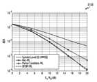
21A is a graph illustrating BER performance according to various embodiments and BER performance according to an existing method in a MIMO-OFDM system.
21B is a graph illustrating BER performance according to various embodiments and BER performance according to an existing method in a MIMO-FBMC system.
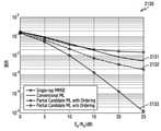
21C is a graph illustrating BER performance according to various embodiments and BER performance according to an existing method, taking into account whether an ordering algorithm is applied or not, in a MIMO-OFDM system.
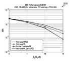
22A is a graph illustrating BER performance according to various embodiments and BER performance according to an existing method in a MIMO-OFDM system.
22B is a graph illustrating BER performance according to various embodiments and BER performance according to an existing method in a MIMO-FBMC system.
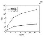
23 is a diagram illustrating complexity of a modulation order according to various embodiments and a conventional method.
이하 첨부된 도면을 참고하여 다양한 실시 예들의 동작 원리를 상세히 설명한다. 하기에서 다양한 실시 예들을 설명에 있어 관련된 공지 기능 또는 구성에 대한 구체적인 설명이 발명의 요지를 불필요하게 흐릴 수 있다고 판단되는 경우에는 그 상세한 설명을 생략할 것이다. 그리고 후술되는 용어들은 다양한 실시 예들에서의 기능을 고려하여 정의된 용어들로서 이는 사용자, 운용자의 의도 또는 관례 등에 따라 달라질 수 있다. 그러므로 그 정의는 본 명세서 전반에 걸친 내용을 토대로 내려져야 할 것이다.Hereinafter, the principle of operation of various embodiments will be described in detail with reference to the accompanying drawings. In the following, when it is determined that a detailed description of a known function or configuration related to various embodiments may unnecessarily obscure the gist of the present invention, a detailed description thereof will be omitted. In addition, the terms to be described later are terms defined in consideration of functions in various embodiments, which may vary according to intentions or customs of users and operators. Therefore, the definition should be made based on the content throughout this specification.
이하 본 개시에서는 멀티 캐리어 및 MIMO 시스템에서 최대 우도(maximum likelihood)를 검출하기 위한 기법에 대해 설명한다.Hereinafter, a technique for detecting maximum likelihood in multi-carrier and MIMO systems will be described in the present disclosure.
이하 설명에서 사용되는 정보를 지칭하는 용어(예: 신호, 심볼), 결과를 지칭하는 용어(예: 검출결과), 수신 장치의 구성 요소를 지칭하는 용어(예: 수신부, 제어부) 등은 설명의 편의를 위해 예시된 것이다. 따라서, 본 발명이 후술되는 용어들에 한정되는 것은 아니며, 동등한 기술적 의미를 가지는 다른 용어가 사용될 수 있다.Terms that refer to information (eg, signal, symbol) used in the description below, terms that refer to results (eg, detection result), and terms that refer to components of a receiving device (eg, receiver, control unit), etc. It is illustrated for convenience. Accordingly, the present invention is not limited to the terms described below, and other terms having equivalent technical meanings may be used.
멀티 캐리어 시스템들은 다양한 이유로 인해 캐리어간 간섭(inter-carrier interference, ICI) 심볼간 간섭(inter-symbol interference, ISI)가 발생하게 된다. OFDM (Orthogonal Frequency Division Multiplexing)의 경우 시간의 변화에 의존적인 환경(time-invariant) 또는 수신기의 오실레이터(oscillator)의 문제 등으로 인해 ICI가 발생한다. FBMC (Filter Bank Multi Carrier) 의 경우 지연확산(delay spread) 환경에서 필터의 직교성이 손상되어 ICI, ISI가 모두 발생한다. 상기 간섭들로 인해 멀티캐리어 시스템에서 최대 우도 검출 방식(maximum likelihood detection, 이하 'ML 검출')의 적용이 어렵다. 기존의 제안되었던 ML 검출 방식들은 가능한 심볼군들을 모두 고려하기 때문에 복잡도가 지나치게 증가하여, 실제로 구현이 불가능한 문제가 있었다. 또한 채널 이득이 강한 영역에 대해서만 검출을 수행할 경우, 다른 캐리어를 포함하는 영역에 대하여 간섭의 영향을 고려할 수 없는 문제가 있었다.In multi-carrier systems, inter-carrier interference (ICI) inter-symbol interference (ISI) occurs due to various reasons. In the case of OFDM (Orthogonal Frequency Division Multiplexing), ICI occurs due to a time-invariant environment or a problem with an oscillator of a receiver. In the case of FBMC (Filter Bank Multi Carrier), both ICI and ISI occur because the orthogonality of the filter is damaged in a delay spread environment. Due to the interferences, it is difficult to apply a maximum likelihood detection (hereinafter, 'ML detection') method in a multicarrier system. Existing proposed ML detection methods have a problem in that they cannot be implemented in practice because complexity is excessively increased because all possible symbol groups are considered. In addition, when detection is performed only in a region having a strong channel gain, there is a problem in that the influence of interference cannot be considered on a region including other carriers.
톤 별(per-tone)로 수행되는 기존의 ML 검출은 신호간섭비(signal-to interference ratio)의 일정크기를 보장하지 못하기 때문에 오류가 발생한다. 이와 같은 오류를 방지하고자, 멀티캐리어 시스템 전체에 대해서 ML 검출을 수행하려는 경우, 연산량이 많아져 실제로 적용이 불가능하다.Conventional ML detection performed on a per-tone basis does not guarantee a certain size of a signal-to-interference ratio, so an error occurs. In order to prevent such an error, in the case of performing ML detection on the entire multicarrier system, the amount of computation increases and thus it is not practically applicable.
멀티캐리어 시스템에서 간섭은 일반적인 MIMO 시스템과는 달리 특정 부분에 집중되어 있는 형태를 가지고 있다. 따라서 집중되어 있는 부분에 대하여 일정한 처리를 하면, 간섭의 효과를 최소화할 수 있다. 복잡도가 낮은 펄톤 선형 리시버(per-tone linear receiver)를 사용하여 임시 심볼들(

상기 임시 심볼들(

상기 임시 심볼들(


본 개시의 다양한 실시 예에 따를 때, OFDM 환경에서는 캐리어 주파수 오프셋(carrier frequency offset, CFO)이 존재하는 환경에서 최적의 ML 검출의 비트오류율(bit error rate, BER)에 근접할 수 있다. 일정한 파라미터에서는 BER
본 개시의 다양한 실시 예에 따를 때, FBMC 환경에서는 간섭제거를 동반하는 ML 검출에 비해 큰 이득을 보인다. OFDM 환경보다 낮은 BER 성능을 갖는 점은 정렬 알고리즘의 최적화와 심볼들과 수신 신호와의 거리 비교를 통해 개선할 수 있다.According to various embodiments of the present disclosure, the FBMC environment shows a large gain compared to ML detection accompanied by interference cancellation. The point having a lower BER performance than the OFDM environment can be improved by optimizing the alignment algorithm and comparing the distances between symbols and the received signal.
본 개시의 다양한 실시 예에 따른 장치는 간섭을 제거하는 과정 없이 멀티 캐리어 시스템에서 ML 검출을 수행하는 장점이 있고, 낮은 복잡도를 유지하면서 원하는 BER 성능을 얻을 수 있는 장점이 있다. 또한 간섭을 고려하기 위해 인접한 서브캐리어를 포함하여 ML 검출을 수행하는 'banded ML'에 비해 복잡도가 크게 줄어드는 장점이 있다. 또한 주파수 도메인에 대한 송신 안테나 별 평균 채널 이득은 전체 안테나 영역에 대한 특성을 비교적 잘 나타낼 수 있다. ML 검출과정에서 안테나에 대한 정렬은 불가능한데, 본 개시의 다양한 실시 예에서는 송신 장치의 안테나에서의 채널 이득에 따라 정렬을 함으로써, 2차원적인 문제를 1차원적으로 치환한다는 장점이 있다.The apparatus according to various embodiments of the present disclosure has the advantage of performing ML detection in a multi-carrier system without a process of removing interference, and has the advantage of obtaining desired BER performance while maintaining low complexity. In addition, compared to 'banded ML' in which ML detection is performed including adjacent subcarriers in consideration of interference, complexity is greatly reduced. In addition, the average channel gain for each transmit antenna in the frequency domain may represent the characteristics of the entire antenna area relatively well. It is impossible to align the antenna in the ML detection process, but in various embodiments of the present disclosure, there is an advantage in that a two-dimensional problem is one-dimensionally replaced by aligning according to a channel gain in an antenna of a transmitting apparatus.
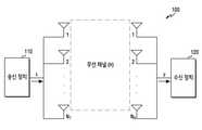
도 1은 무선 통신 시스템에서 송신 장치와 수신 장치를 도시한다.1 shows a transmitting apparatus and a receiving apparatus in a wireless communication system.
상기 도 1을 참고하면, MIMO시스템은 송신 장치 110에


수학식 1에서, s는 송신 장치 110이 송신하는 신호, y는 수신 장치 120이 수신하는 신호, n은 실제 전송시에 발생하는 잡음이다. [


도 2는 일반적인 ML 검출의 성상도를 도시한다.2 shows a constellation of a typical ML detection.
상기 도 2를 참고하면, 성상도 200은 변조방식 4 QAM (Quadrature Amplitude Modulation)에 따른 성상도를 나타낸다. 성상도 200은 수신벡터 210을 포함할 수 있다. 상기 벡터 210은 수신 장치 120에서 수신되는 상기 신호 y의 일부 신호에 대응될 수 있다. 성상도 200은 성상점 220, 221, 222, 223을 포함할 수 있다. 수신벡터 210은 상기 4개의 성상점 중 하나에 대응될 수 있다. 수신 장치는 수신벡터210부터 성상점 220, 221, 222, 223까지의 거리를 각각 측정한다. 거리 230, 231, 232, 233에 각각 대응된다. 상기 성상점 220, 221, 222, 223은 각각
상기 거리가 가까울 수록, 실제 신호가 갖는 심볼값과 같을 확률이 커질 수 있다. 성상도 200에서, 수신 장치는 상기 측정된 거리들 중에서 가장 작은 값인 상기 거리 230을 결정할 수 있다. 상기 수신 장치는 상기 거리 230에 대응하는 상기 성상점 220을 결정할 수 있다. 상기 결정된 성상점에 대응되는


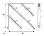
도 3a는 MIMO-OFDM(Multiple Input Multiple Output Orthogonal Frequency Division Multiplexing) 시스템에서 유효 채널(effective channel) 신호의 세기를 도시한다.3A illustrates the strength of an effective channel signal in a Multiple Input Multiple Output Orthogonal Frequency Division Multiplexing (MIMO-OFDM) system.
상기 도 3a를 참고하면, 그래프 300의 가로축 301은 송신 장치의 서브캐리어의 인덱스, 상기 그래프 300의 세로축 302는 수신 장치의 서브캐리어 인덱스를 나타낸다. 하나의 서브캐리어 인덱스는 하나의 물리적 서브캐리어 및 하나의 안테나 쌍의 조합에 의해 특정될 수 있다. 즉, 상기 서브캐리어 인덱스의 최대값은 안테나의 개수 및 서브캐리어의 개수에 따라 정해질 수 있다. 도 3a에 도시된 바와 같이, 가로축 301은 128개의 인덱스, 세로축 302는 128개의 인덱스를 가질 수 있다. 송신 장치의 안테나 개수는 2개, 수신 장치의 안테나 개수는 2개, 서브캐리어의 개수는 64개이고 따라서 송신단과 수신단은 모두 총 128개의 유효 서브캐리어들을 가질 수 있다. 송신 장치의 제1 안테나와 수신 장치의 제1 안테나 간의 유효채널은 제2 사분면 312, 송신 장치의 제1 안테나와 수신 장치의 제2 안테나 간의 유효채널은 제1 사분면 314, 송신 장치의 제2 안테나와 수신 장치의 제1 안테나 간의 유효채널은 제2 사분면 311, 송신 장치의 제2 안테나와 수신 장치의 제2 안테나 간의 유효채널은 제4 사분면 311일 수 있다. 선의 색깔이 진할수록 강한 신호의 세기를 의미하고, 선의 색깔이 연할수록 낮은 신호의 세기를 의미할 수 있다.Referring to FIG. 3A , the
상기 그래프 300을 참고할 때, 인접하지 아니한 서로 다른 캐리어들간의 이득이 영(0)에 근접할 수 있다. 그러나 상기 송신 장치 및 상기 수신 장치의 안테나들 각각 동일한 캐리어에서 가장 높은 이득을 가짐이 확인될 수 있다.Referring to the
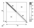
도 3b는 SISO-FBMC(Single Input Single Output Filter Bank Multi Carrier) 시스템에서 유효 채널 신호의 세기를 도시한다.3B shows the strength of an effective channel signal in a SISO-FBMC (Single Input Single Output Filter Bank Multi Carrier) system.
상기 도 3b를 참고하면, 상기 시스템은 듀얼 필터뱅크 FBMC(dual filterbank FBMC)일 수 있다. 상기 듀얼 필터뱅크 FBMC는 4개의 FBMC 서브-심볼들을 가질 수 있다. 그래프 350의 가로축 351은 송신 장치의 서브캐리어들의 인덱스, 상기 그래프 350의 세로축 352는 수신 장치의 서브캐리어들의 인덱스를 도시한다. 도 3b에 도시된 바와 같이, 가로축 351은 64개의 인덱스, 세로축 352는 64개의 인덱스를 가질 수 있다.Referring to FIG. 3B, the system may be a dual filterbank FBMC (dual filterbank FBMC). The dual filterbank FBMC may have 4 FBMC sub-symbols. A
상기 그래프 350의 정사각형은 256 X 256의 크기를 가질 수 있다. 상기 그래프 350의 상기 정사각형을 4등분 했을 때, 128 x 128 크기의 4개의 정사각형이 생성될 수 있다. 상기 4개의 정사각형은 각각 상기 4개의 FBMC 서브-심볼들에 대응될 수 있다. 상기 4개의 정사각형 각각은 필터간 유효 채널을 나타낼 수 있다. 상기 4개의 정사각형은 각각 가로축 32개의 서브캐리어, 세로축 32개의 서브캐리어를 가질 수 있다. 상기 4개의 정사각형은 각각 128 X 128의 크기를 가질 수 있다. 제1 사분면 364, 제3 사분면 361는 서로 다른 필터 간 유효 채널이므로, 이득이 거의 없으나, 제2 사분면 362, 제4 사분면 363은 동일한 필터간의 유효 채널이므로, 대각선 방향 부분에서 가장 높은 이득을 가짐이 확인될 수 있다. 제4 사분면 363의 경우에는 필터의 특성이 좋지 못해서, 이에 대응하는 FBMC 서브-심볼들로부터 간섭의 영향이 더 크게 나타날 수 있다.The square of the graph 350 may have a size of 256
도 3a 및 도 3b에 도시된 바와 같이, 멀티캐리어 시스템에서 유효채널을 수신하는 경우, 신호가 일정 영역에서 집중되어 있는 현상이 나타낼 수 있다. 신호의 세기가 강할 경우, 주위 캐리어들에 미치는 영향력이 강하고 이에 따라 간섭의 영향도 강할 수 있다. 다양한 실시 예에 따를 때, 상기 집중되어 있는 부분을 고려하여 수신되는 신호에 일정한 처리를 수행한 뒤 신호를 검출하는 경우, 보다 효율적으로 간섭의 효과를 제거할 수 있다. 상기 간섭은 캐리어 간의 간섭 또는 심볼간의 간섭일 수 있다.As shown in FIGS. 3A and 3B , when an effective channel is received in a multicarrier system, a phenomenon in which signals are concentrated in a certain area may be exhibited. When the signal strength is strong, the influence on the surrounding carriers is strong, and thus the influence of the interference may also be strong. According to various embodiments, when a signal is detected after a predetermined process is performed on a received signal in consideration of the concentrated portion, the effect of interference may be more efficiently removed. The interference may be inter-carrier interference or inter-symbol interference.
도 4는 무선 통신 시스템에서 멀티캐리어를 고려한 복수의 심볼군들을 도시한다.4 illustrates a plurality of symbol groups in consideration of multicarriers in a wireless communication system.
상기 도 4를 참고하면, 심볼군 410은 송신 장치 110에서 송신한 신호 s일 수 있다. 각 심볼들은 서로 다른 캐리어에 대응될 수 있다. 4 QAM의 변조방식을 따르는 경우, 하나의 캐리어에 4개의 심볼들(

본 개시의 다양한 실시 예에 따를 때, 송신 장치 110에서 송신한 신호 s에 대하여 초기 검출결과 430을 생성할 수 있다. 초기 검출결과 430에서 채널 이득에 기반하여 검출영역 435를 결정할 수 있다. 가능한 심볼들을 초기 검출결과 430의 검출영역 435에 삽입하여 복수의 심볼군들 440을 생성할 수 있다. 상기 검출영역 435는 검출영역 445에 대응될 수 있다. 4 QAM의 변조방식을 따르는 경우, 검출영역 445에 4개의 심볼들이 대응될 수 있다. 다른 영역의 심볼들은 ML 검출시 앞서 검출된 값으로 고정될 수 있다. 상기 검출영역 445의 검출이 끝나면 그 외의 영역에 대하여 ML 검출을 수행할 수 있다. 상기 그 외의 영역은 검출영역 455를 포함할 수 있다. 상기 도 4에 도시된 바와 같이, 검출영역은 캐리어 단위로 이루어질 수 있다. 상기 복수의 심볼군들 440은 4개의 심볼군들을 가질 수 있다. 총 4개의 캐리어가 사용되므로, 전체에 대하여 ML 검출이 수행되는 경우, 전체 복수의 심볼군들은 16개(4 X 4)의 심볼군들을 가질 수 있다. 상기 복수의 심볼군들 440의 경우 초기 검출결과 430을 기반으로 심볼군들을 생성할 수 있다. 따라서 실제 신호의 간섭의 영향을 고려할 수 있다. 또한 더 적은 심볼군의 개수를 후보들로서 가질 수 있다. 이에 따라, 복수의 심볼군들 420 보다 복잡도가 감소할 수 있다.According to various embodiments of the present disclosure, an
도 5는 무선 통신 시스템에서 멀티캐리어 및 다수의 안테나들을 고려한 심볼군을 도시한다.5 shows a symbol group in consideration of a multi-carrier and a plurality of antennas in a wireless communication system.
상기 도 5를 참고하면, 축 510은 송신 장치의 안테나, 축 520은 캐리어, 축 530은 신호가 가질 수 있는 심볼들을 도시한다. 사각형 540은 ML 검출시 가능한 심볼군들 중 하나의 심볼군의 크기를 나타낼 수 있다. 상기 심볼들의 개수는 변조방식에 따라 결정될 수 있다.Referring to FIG. 5 , an
상기 도 5에서 도시된 바와 같이, 송신 장치의 안테나는 2개(


이하 설명에서 상기 MIMO 시스템은 2개의 송신 안테나들을 구비하는 송신 단과 2개의 수신 안테나를 구비하는 수신 단을 포함하여 구성되는 것으로 가정한다. 캐리어의 개수는 4개이고, 변조방식은 다른 설명이 없는 경우 4 QAM을 가정한다. 상기 송신 단과 수신 단이 다수 개의 안테나를 구비하는 경우 동일하게 적용할 수 있다.In the following description, it is assumed that the MIMO system is configured to include a transmitting end having two transmit antennas and a receiving end having two receive antennas. The number of carriers is 4, and the modulation method assumes 4 QAM unless otherwise specified. The same can be applied when the transmitting end and the receiving end are provided with a plurality of antennas.
도 6은 일 실시 예에 따른 수신 장치를 도시한다. 상기 수신 장치는 도 1에 개시된 상기 수신 장치 120일 수 있다.6 illustrates a receiving device according to an embodiment. The receiving device may be the receiving
상기 도 6을 참고하면, 수신 장치 120은 수신부 610과 제어부 620으로 구성될 수 있다. 수신부 610은 신호를 수신할 수 있다. 즉, 수신부 610은 무선 채널을 통해 신호를 송수신하기 위한 기능들을 수행한다. 예를 들어, 수신부 610은 시스템의 물리 계층 규격에 따라 RF(radio frequency) 신호, 기저대역 신호 간 변환 기능을 수행한다. 예를 들어, 데이터 수신 시, 수신부 610은 적어도 하나의 안테나를 통해 RF 신호를 수신하고, RF 신호에 대한 처리 후, 기저대역 신호로 하향변환하고, 디지털 신호로 변환한다. 예를 들어, 수신부 610는 수신 필터, 증폭기, 믹서(mixer), 오실레이터(oscillator), DAC(digital to analog convertor), ADC(analog to digital convertor) 등을 포함할 수 있다. 다수의 수신 안테나들이 구비된 경우, 수신부 610는 다수의 RF 체인들을 포함할 수 있다. 수신부 610는 'RF 처리부', '트랜시버' 등으로 지칭될 수 있다.Referring to FIG. 6 , the
제어부 620은 수신부 610를 통해 수신된 신호를 처리한다. 예를 들어, 제어부 620는 송신 장치로부터 다수의 서브캐리어들을 통해 수신되는 신호들에 대한 검출을 수행할 수 있다. 제어부 620는 '기저대역 처리부'로 지칭될 수 있다.The
예를 들어, 상기 제어부 620은 상기 송신 장치로부터 복수의 캐리어들을 통해 수신되는 신호에 기반하여 초기 검출결과를 생성하도록 구성되고, 채널 이득에 기반하여 초기 검출결과에서 제1 검출영역을 결정하도록 구성되고, 가능한 심볼들을 상기 초기 검출결과의 상기 제1 검출영역에 삽입하여 제1 복수의 심볼군들을 생성하도록 구성되고, 상기 제1 복수의 심볼군들 중 최대 우도를 갖는 제1 심볼군에 기반하여 제1 검출결과를 생성하도록 구성될 수 있다.For example, the
다양한 실시 예에 따를 때, 상기 제어부는 상기 초기 검출결과에서 상기 제1 검출영역에 대응하지 않는 제2 검출영역을 결정하도록 구성되고, 가능한 심볼들을 상기 제1 검출결과의 상기 제2 검출영역에 삽입하여 제2 복수의 심볼군들을 생성하도록 구성되고, 상기 제2 복수의 심볼군들 중 최대 우도를 갖는 제2 심볼군에 기반하여 제2 검출결과를 생성하도록 구성될 수 있다.According to various embodiments, the control unit is configured to determine a second detection area that does not correspond to the first detection area in the initial detection result, and inserts possible symbols into the second detection area of the first detection result. to generate a second plurality of symbol groups, and may be configured to generate a second detection result based on a second symbol group having a maximum likelihood among the second plurality of symbol groups.
다양한 실시 예에 따를 때, 상기 제어부는 상기 초기 검출결과 및 상기 제2 검출결과에 기반하여 제3 검출영역을 결정하도록 구성되고, 가능한 심볼들을 상기 제3 검출영역에 삽입하여 제3 복수의 심볼군들을 생성하도록 구성되고, 상기 제3 복수의 심볼군들 중 최대 우도를 갖는 제3 심볼군에 기반하여 제3 검출결과를 생성하도록 구성될 수 있다. 상기 제3 검출영역은 상기 초기 검출결과에서 상기 제2 검출결과에 대응하지 않는 검출영역일 수 있다.According to various embodiments, the controller is configured to determine a third detection region based on the initial detection result and the second detection result, and inserts possible symbols into the third detection region to insert a third plurality of symbol groups. and generating a third detection result based on a third symbol group having a maximum likelihood among the third plurality of symbol groups. The third detection region may be a detection region that does not correspond to the second detection result in the initial detection result.
다양한 실시 예에 따를 때, 상기 제1 검출영역은 상기 복수의 캐리어들 중 적어도 하나의 캐리어에 대응될 수 있다.According to various embodiments, the first detection area may correspond to at least one of the plurality of carriers.
다양한 실시 예에 따를 때, 상기 적어도 하나의 캐리어는 상기 송신 장치에 포함된 안테나의 채널 이득의 크기에 기반하여 결정될 수 있다.According to various embodiments, the at least one carrier may be determined based on a size of a channel gain of an antenna included in the transmitting apparatus.
다양한 실시 예에 따를 때, 상기 적어도 하나의 캐리어는 상기 수신된 신호의 SIR(signal-to-interference ratio) 값에 따라 결정되고, 상기 SIR 값은 상기 송신 장치와 상기 수신 장치 간의 채널 상태 또는 필터의 특성 중 적어도 하나를 기반으로 측정되는 값일 수 있다.According to various embodiments, the at least one carrier is determined according to a signal-to-interference ratio (SIR) value of the received signal, and the SIR value is a channel state between the transmitting device and the receiving device or a filter. It may be a value measured based on at least one of the characteristics.
다양한 실시 예에 따를 때, 상기 제1 검출영역은 상기 신호의 지연확산(delay spread)의 정도 또는 상기 신호의 변조 차수 중 적어도 어느 하나에 기반하여 결정될 수 있다.According to various embodiments, the first detection area may be determined based on at least one of a degree of delay spread of the signal or a modulation order of the signal.
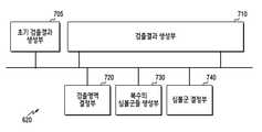
도 7은 일 실시 예에 따른 수신 장치의 제어부를 도시한다. 상기 제어부는 도 6에 개시된 제어부 620일 수 있다.7 illustrates a control unit of a receiving device according to an embodiment. The control unit may be the
상기 도 7을 참고하면, 제어부 620은 초기 검출결과 생성부 705, 검출결과 생성부 710, 검출영역 결정부 720, 복수의 심볼군들 생성부 730, 심볼군 결정부 740으로 구성될 수 있다.Referring to FIG. 7 , the
초기 검출결과 생성부 705는 상기 수신 장치에 포함된 수신부로부터 수신 받은 신호를 입력으로 할 수 있다. 상기 입력에 대응하여, 심볼군의 형태인 상기 초기 검출결과를 생성할 수 있다. 상기 초기 검출결과를 출력으로 할 수 있다.The initial
검출결과 생성부 710은 심볼군을 생성할 수 있다. 상기 심볼군은 전술한 도 6의 제어부에서 생성되는 제1 검출결과, 후술할 제2 검출결과 또는 후술할 제3 검출결과 중 어느 하나일 수 있다. 상기 심볼군 결정부 740에 의해 결정된 심볼군을 입력으로 할 수 있다. 검출결과가 생성된 뒤에, 재검출이 필요하다고 결정되는 경우, 상기 검출결과를 출력으로 할 수 있다. 상기 출력은 상기 검출영역 결정부 720의 입력이 될 수 있다.The
검출영역 결정부 720은 채널 이득에 기반하여 검출영역을 결정할 수 있다. 상기 초기 검출결과 또는 상기 검출결과를 입력으로 할 수 있다. 상기 검출영역을 결정하는 과정은 ML 검출의 순서를 의미할 수 있다. 또한 상기 검출영역을 결정하는 과정은 ML 검출을 수행하는 경우, 가능한 심볼들의 조합인 복수의 심볼군들 중 하나의 심볼군의 크기를 의미할 수 있다. 상기 검출영역은 송신안테나들의 채널 이득, 지연확산의 영향, 채널의 상태, 필터의 특성, 신호의 변조 차수에 기반하여 결정될 수 있다. 상기 검출영역이 결정되면, 이를 출력으로 할 수 있다.The
복수의 심볼군들 생성부 730은 상기 검출영역을 입력으로 할 수 있다. 검출결과에서 상기 검출영역에 가능한 심볼들을 모두 삽입하여 복수의 심볼군들을 생성할 수 있다. 상기 검출영역이 넓을수록 복수의 심볼군들의 개수는 지수적으로 증가할 수 있다. 상기 복수의 심볼군들을 출력으로 할 수 있다.The plurality of
심볼군 결정부 740은 상기 복수의 심볼군들을 입력으로 할 수 있다. 상기 복수의 심볼군들을 후보로 하여, ML 검출을 수행할 수 있다. 상기 복수의 심볼군들 중 유클리디안 거리의 합이 최소가 되는 하나의 심볼군을 결정할 수 있다. 결정된 하나의 심볼군을 출력으로 할 수 있다.The
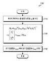
도 8은 일 실시 예에 따른 제1 검출결과를 생성하는 동작을 도시한 흐름도이다. 이러한 동작 흐름은 도 1에 도시된 수신 장치 120에 의해 수행될 수 있다. 즉 도 8은 수신 장치 120의 동작 방법을 예시한다.8 is a flowchart illustrating an operation of generating a first detection result according to an exemplary embodiment. Such an operation flow may be performed by the receiving
상기 도 8을 참고하면, 810 단계에서, 수신 장치는 송신 장치로부터 복수의 캐리어들을 통해 신호를 수신한다. 상기 수신 장치는 수신부를 이용하여 신호를 수신할 수 있다. 상기 수신부는 상기 수신 장치 120에 포함된 수신부 610일 수 있다. 상기 송신 장치는 도 1의 송신 장치 110일 수 있다.Referring to FIG. 8 , in
820 단계에서, 제어부는 상기 수신된 신호에 기반하여 초기 검출결과(
830 단계에서, 상기 제어부는 채널 이득에 기반하여 상기 초기 검출결과에서 제1 검출영역을 결정하도록 구성될 수 있다. 상기 채널 이득은 송신 안테나 채널 이득의 평균값에 대응될 수 있다. 채널 이득이 높을수록 다른 검출영역에 미치는 간섭의 영향이 높고, 채널 이득이 낮을수록 다른 검출영역에 미치는 간섭의 영향이 낮을 수 있다. 상기 검출영역들은 적어도 하나의 캐리어에 대응될 수 있다. 따라서 채널 이득이 높은 상기 제1 검출영역에 대하여 먼저 ML 검출을 수행하게 되면, 다른 검출영역에 대하여 먼저 ML 검출을 수행했을 경우보다, 캐리어 간섭의 영향을 상대적으로 덜 받을 수 있다.In
840 단계에서, 상기 제어부는 가능한 심볼들을 상기 초기 검출결과의 상기 제1 검출영역에 삽입하여 제1 복수의 심볼군들을 생성하도록 구성될 수 있다. 상기 신호의 변조방식은 4 QAM 변조방식일 수 있다. 4 QAM 변조방식인 경우, 상기 가능한 심볼들은 4가지일 수 있다. 상기 캐리어들 및 안테나의 개수를 고려할 때, 제1 검출영역의 크기를

850 단계에서, 상기 제어부는 상기 제1 복수의 심볼군들 중 최대 우도를 갖는 제1 심볼군에 기반하여 제1 검출결과를 생성하도록 구성될 수 있다. 상기 제1 복수의 심볼군들 각각에 대하여 ML 검출을 수행할 수 있다.In
상기 ML 검출은 다음과 같은 과정으로 수행될 수 있다. 상기 제1 복수의 심볼군들 중 임의의 심볼군을 선택할 수 있다. 상기 선택된 임의의 심볼군의 심볼 각각에 대하여 상기 신호와의 유클리디안 거리(Euclidean distance)를 측정하고, 이들을 모두 더하여 합산값을 생성할 수 있다. 상기 합산값의 크기가 최소가 되는 심볼군을 상기 제1 심볼군으로 결정할 수 있다. 상기 제1 심볼군은 상기 제1 검출결과에 대응될 수 있다.The ML detection may be performed as follows. Any symbol group from among the first plurality of symbol groups may be selected. For each symbol of the selected arbitrary symbol group, a Euclidean distance with the signal may be measured, and a sum value may be generated by adding them all. A symbol group having the smallest size of the sum value may be determined as the first symbol group. The first symbol group may correspond to the first detection result.
도 9는 일 실시 예에 따른 제2 검출결과를 생성하는 동작을 도시한 흐름도이다. 이러한 상기 도 9를 참고하면, 910 단계에서, 제어부는 상기 초기 검출결과에서 제1 검출영역에 대응하지 않는 제2 검출영역을 결정하도록 구성될 수 있다. 상기 초기 검출결과에서 채널 이득이 높은 상기 제1 검출영역에 대하여 ML 검출이 수행되었다. 따라서 상기 초기 검출결과에서 상기 제1 검출영역에 대응하지 않는 부분에 대하여 ML 검출을 수행시, 상대적으로 간섭의 영향이 적어진 상태에서 수행이 가능할 수 있다. 상기 제1 검출영역에 대응하지 않는 부분은 제2 검출영역일 수 있다.9 is a flowchart illustrating an operation of generating a second detection result according to an exemplary embodiment. Referring to FIG. 9 , in
920 단계에서, 상기 제어부는 가능한 심볼들을 상기 제1 검출결과의 상기 제2 검출영역에 삽입하여 제2 복수의 심볼군들을 생성하도록 구성될 수 있다. 상기 신호의 변조방식은 4 QAM 변조방식일 수 있다. 4 QAM 변조방식인 경우, 상기 가능한 심볼들은 4가지일 수 있다. 상기 캐리어들 및 안테나의 개수를 고려할 때, 제2 검출영역의 크기를

930 단계에서, 상기 제어부는 상기 제2 복수의 심볼군들 중 최대 우도를 갖는 제2 심볼군에 기반하여 제2 검출결과를 생성하도록 구성될 수 있다. 상기 제2 복수의 심볼군들 각각에 대하여 ML 검출을 수행할 수 있다. 상기 ML 검출은 상기 도 8에서 수행된 상기 제1 검출영역의 ML 검출과 같은 방식으로 이루어질 수 있다. 제2 검출결과는 초기 검출결과에서 모든 영역에 대하여 ML 검출이 수행되고 난 후의 검출결과에 대응될 수 있다.In
동작 900은 반복적인 과정이 포함될 수 있다. 상기 910 단계에서, 상기 제2 검출영역은 복수의 검출영역으로 분할될 수 있다. 상기 복수의 검출영역 중 임의의 검출영역의 크기는 상기 제1 검출영역과 같은 크기일 수 있다. 상기 복수의 검출영역에 대한 검출순서를 결정할 수 있다. 본 개시의 다양한 실시 예에 따를 때, 상기 검출순서는 송신 장치의 안테나의 평균 채널 이득에 기반하여 결정될 수 있다. 또한 상기 검출순서는 지연확산(delay spread)의 영향 정도에 기반하여 결정될 수 있다.
상기 920 단계에서, 상기 검출순서에 따라 ML 검출이 반복적으로 수행될 수 있다. 상기 복수의 검출영역 중 i번째 검출영역에 대하여 ML 검출을 수행하는 경우, i-1번째 검출영역까지 수행된 ML 검출의 결과는 누적되어 반영된다. 따라서 본 개시의 다양한 실시 예에 따를 때, 복잡도는 검출결과의 크기 와 검출영역의 크기의 비율만큼 지수적으로 감소하는 반면, 채널 이득이 큰 캐리어에 의한 간섭의 영향을 고려할 수 있다.In
상기 930 단계에서, 상기 복수의 검출영역들 모두에 대하여 ML 검출을 수행하는 경우, 상기 제2 검출결과가 생성될 수 있다. 상기 제2 검출결과는 캐리어간의 간섭의 영향을 고려하여 생성될 수 있다. 또한 전체에 대한 복수의 심볼군들을 생성하여 ML 검출을 수행하는 경우보다, 검출영역을 분할하여 ML 검출을 수행하는 경우, 복잡도가 감소할 수 있다.In
도 10은 일 실시 예에 따른 제3 검출결과를 생성하는 동작을 도시한 흐름도이다. 이러한 상기 도 10을 참고하면, 1010 단계에서, 제어부는 상기 초기 검출결과 및 상기 제2 검출결과에 기반하여 제3 검출영역을 결정하도록 구성될 수 있다.10 is a flowchart illustrating an operation of generating a third detection result according to an exemplary embodiment. Referring to FIG. 10 , in
다양한 실시 예에 따를 때, 상기 제3 검출영역은 상기 초기 검출결과와 상기 제2 검출결과를 심볼들마다 비교하여 결정할 수 있다. 비교하여 대응되지 않는 영역으로 결정할 수 있다. 이에 대한 구체적인 동작들은 후술한다.According to various embodiments, the third detection area may be determined by comparing the initial detection result and the second detection result for each symbol. It can be determined as a non-corresponding region by comparison. Specific operations for this will be described later.
다양한 실시 예에 따를 때, 상기 제3 검출영역은 상기 수신되는 신호와 상기 초기 검출결과 사이의 유클리디안 거리(Euclidean distance) 및 상기 수신되는 신호와 상기 제1 검출결과 사이의 유클리디안 거리에 기반하여 결정될 수 있다. 이에 대한 구체적인 동작들은 후술한다.According to various embodiments, the third detection region is a Euclidean distance between the received signal and the initial detection result and a Euclidean distance between the received signal and the first detection result. can be determined based on Specific operations for this will be described later.
다양한 실시 예에 따를 때, 상기 제3 검출영역은 상기 복수의 캐리어들 중 적어도 하나의 캐리어의 채널 이득이 최대 우도를 갖는 심볼군 검출에 필요한 SIR(signal-to-interference ratio)의 평균값보다 작은 경우, 상기 적어도 하나의 캐리어에 대응될 수 있다. 이에 대한 구체적인 동작들은 후술한다.According to various embodiments, when the channel gain of at least one of the plurality of carriers is smaller than the average value of the signal-to-interference ratio (SIR) required for detecting the symbol group having the maximum likelihood, the third detection area is , may correspond to the at least one carrier. Specific operations for this will be described later.
도 11은 일 실시 예에 따른, 수신부에 의해 수신된 신호에 기반하여 상기 초기 검출결과를 생성하는 동작을 도시한 흐름도이다. 이러한 동작 흐름은 도 1에 도시된 수신 장치 120에 의해 수행될 수 있다. 상기 도 11을 참고하면, 1110 단계에서, 상기 수신 장치 120은 복수의 캐리어들에 대하여, 캐리어들 각각 신호열을 수신할 수 있다. 캐리어 각각에 대하여 톤 별 선형 수신기(per-tone linear receiver)를 통하여 수신될 수 있다. k번째 캐리어에 대하여 수신하는 경우, 수신되는 신호열은
1120 단계에서, 수신 장치는 초기 검출열을 생성한다. 초기 검출열의 생성 시, 수신 장치는 서브캐리어 간 간섭을 고려하지 아니할 수 있다. 구체적으로, 수신 장치는 채널 행렬, 채널 행렬의 허미션(hermitian) 행렬, 잡음 벡터를 이용하여 가중치 행렬을 생성하고, 가중치 행렬을 수신 신호에 곱함으로써, 초기 검출열을 생성할 수 있다. 예를 들어, 상기 신호열


1130 단계에서, 캐리어 각각에 대하여 생성된 복수의 초기 검출열들에 기반하여 초기 검출결과(
도 12는 일 다양한 실시 예에 따른 부분 후보에 기반한 최대 우도 검출의 동작을 도시한다.12 illustrates an operation of maximum likelihood detection based on partial candidates according to various embodiments of the present disclosure.
상기 도 12를 참고하면, 상기 동작은 상기 도 6에 도시된 제어부 620에 의해 수행될 수 있다. 캐리어의 개수는 4개인 멀티캐리어 시스템일 수 있다. 송신 안테나의 개수는 2개이고 수신 안테나의 개수는 2개인 MIMO 시스템일 수 있다.Referring to FIG. 12 , the operation may be performed by the
심볼군 1210은 상기 초기 검출결과에 대응될 수 있다. 가로축은 송신 안테나의 개수, 세로축은 캐리어의 개수를 나타낼 수 있다. 상기 멀태캐리어 시스템은 캐리어 1211, 캐리어 1212, 캐리어 1213, 캐리어 1214의 캐리어를 포함할 수 있다. 신호의 변조방식은 4 QAM 변조방식일 수 있다. 4 QAM 변조방식인 경우, 하나의 캐리어, 하나의 안테나가 가질 수 있는 심볼의 경우의 수는 4개이다. 상기 심볼은
제어부 620은 상기 초기 검출결과를 일정한 크기로, 복수의 검출영역으로 분할될 수 있다. 이후, 최대 우도 검출을 수행할 순서를 결정할 수 있다. 상기 검출 순서는 채널 이득에 기반하여 결정될 수 있다. 상기 검출 순서는 송신 안테나의 평균 채널 이득(channel gain)이 큰 안테나를 기준으로 주파수 도메인에서 결정될 수 있다. 상기 검출 순서는 FBMC 시스템에서, 지연확산의 영향을 가장 적게 받은 서브-심볼을 우선적으로 검출하도록 시간 도메인에서 결정될 수 있다. 상기 일정한 크기는 채널 또는 필터의 특성, 변조 방식에 따라 능동적으로 설정 가능하다. 본 개시의 다양한 실시 예에 따를 때, 상기 채널의 상태, 상기 필터의 특성을 기반으로 SIR(signal-to interference ratio)를 측정한 후, SIR을 기반으로 ML 검출에 사용할 서브캐리어의 개수를 조절함으로써 결정될 수 있다. 본 개시의 다양한 실시 예에 따를 때, 상기 일정한 크기는 변조 차수에 따라 결정될 수 있다.The
ML 검출을 가장 먼저 수행할 제1 검출영역을 결정한다. 상기 제1 검출영역은 전술한 바와 같이 일정한 크기를 갖고, 상기 검출 순서에서 첫 번째 검출에 대응된다. 상기 제1 검출영역은 검출영역 1223에 대응될 수 있다. 초기 검출결과 1210은 8개의 자원을 가질 수 있다. 상기 제어부 620은 2개 자원의 크기로 제1 검출영역을 결정할 수 있다.A first detection region in which ML detection is first performed is determined. The first detection region has a constant size as described above, and corresponds to the first detection in the detection sequence. The first detection area may correspond to the
상기 제어부 620은 채널 이득에 기반하여 검출순서를 캐리어 1213에 대응되는 검출영역 1223, 캐리어 1212에 대응되는 검출영역 1232, 캐리어 1214에 대응되는 검출영역 1244, 캐리어 1211에 대응되는 검출영역 1251로 결정할 수 있다. 실제 송신 장치에서 송신한 심볼군은 상기 도 5에 도시된 심볼군일 수 있다. 검출결과 1220은 상기 초기 검출결과 1210에 대응될 수 있다.The
검출결과 1220에서 검출영역 1223에 대하여 ML 검출을 수행하여 검출결과 1230을 생성할 수 있다. 상기 검출영역 1223에서 [

상기 검출결과 1230은 상기 제1 검출결과에 대응될 수 있다. 검출결과 1230에서 검출영역 1232에 대하여 ML 검출을 수행하여 검출결과 1240을 생성할 수 있다. 상기 검출결과 1232에서 [


도 13은 일 실시 예에 따른 상기 제1 검출영역을 결정하는데 필요한 기준들을 도시한다.13 illustrates criteria necessary for determining the first detection area according to an embodiment.
상기 도 13을 참고하면, 상기 제1 검출영역 결정하는 것은 전술한 바와 같이 검출영역의 일정한 크기를 결정하는 것을 의미하고, 검출 순서에서의 우선순위를 결정하는 것을 의미한다. 검출영역의 일정한 크기는 채널의 상태에 따라 결정될 수 있다. 채널의 상태는 송신 안테나의 평균 채널 이득을 포함할 수 있다. 또한 상기 일정한 크기는 변조 차수에 따라 결정될 수 있다. 4 QAM의 경우 변조 차수는 4차일 수 있다. 또한 상기 일정한 크기는 FBMC 시스템에서의 필터의 특성에 따라 결정될 수 있다. 검출영역의 우선순위를 결정하는 순서 알고리즘은 송신 안테나의 평균 채널 이득(channel gain)에 따라 결정될 수 있다. 또한 상기 우선순위는 지연확산(delay spread)의 영향에 따라 결정될 수 있다.Referring to FIG. 13 , determining the first detection region means determining a predetermined size of the detection region as described above, and determining a priority in the detection order. The predetermined size of the detection region may be determined according to the state of the channel. The state of the channel may include an average channel gain of the transmit antenna. Also, the constant size may be determined according to a modulation order. In the case of 4 QAM, the modulation order may be 4th order. In addition, the constant size may be determined according to the characteristics of the filter in the FBMC system. The order algorithm for determining the priority of the detection region may be determined according to the average channel gain of the transmit antenna. Also, the priority may be determined according to the effect of delay spread.
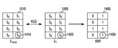
도 14는 일 실시 예에 따른, 심볼 간들 비교를 통해 제3 검출영역을 결정하는 동작을 도시한다.14 illustrates an operation of determining a third detection region through comparison between symbols, according to an embodiment.
상기 도 14를 참고하면, 상기 제3 검출영역은 상기 초기 검출결과에서 상기 제2 검출결과에 대응하지 않는 검출영역일 수 있다. 다양한 실시 예에 따른 장치에 포함된 제어부는 상기 초기 검출결과 1210과 상기 제2 검출결과 1260에 대하여 심볼들 간 XOR 알고리즘을 수행할 수 있다. 상기 XOR 알고리즘은 같은 값에 대해서는 0, 다른 값에 대해서는 1의 결과를 생성할 수 있다. 예를 들어, 심볼 1410은 s3, 심볼 1420은 s1으로 다르므로 검출결과 1400의 상기 심볼 1410 및 상기 심볼 1420에 대응되는 자원에 1의 결과를 생성할 수 있다. 상기 XOR 알고리즘 수행시 상기 검출결과 1400이 생성될 수 있다. 상기 검출결과 1400에서 1을 요소로 갖는 자원은 제3 검출영역에 대응될 수 있다. 즉 1을 요소로 갖는 자원들은 재검출의 대상이 될 수 있다.Referring to FIG. 14 , the third detection region may be a detection region that does not correspond to the second detection result in the initial detection result. The controller included in the apparatus according to various embodiments may perform an XOR algorithm between symbols on the
도 15는 일 실시 예에 따른, 제3 검출영역을 결정하기 위하여 유클리디안 거리(Euclidean distance)를 비교하는 동작을 도시한다. 이러한 상기 도 15를 참고하면, 상기 제3 검출영역은 상기 수신되는 신호와 상기 초기 검출결과 사이의 유클리디안 거리(Euclidean distance) 및 상기 수신되는 신호와 상기 제1 검출결과 사이의 유클리디안 거리에 기반하여 결정될 수 있다.15 illustrates an operation of comparing Euclidean distances to determine a third detection area, according to an embodiment. Referring to FIG. 15, the third detection region is a Euclidean distance between the received signal and the initial detection result and a Euclidean distance between the received signal and the first detection result. can be determined based on
성상도 1500은 변조방식 4 QAM에 따른 성상도를 나타낸다. 성성도 1500은 수신벡터 1510을 포함할 수 있다. 상기 벡터 1510은 수신 장치에서 수신되는 상기 신호의 일부에 대응될 수 있다. 성상도 1500은 성상점 1520, 1521, 1522, 1523을 포함할 수 있다. 상기 성상도 1500은 상기 도 14의 상기 심볼 1410 및 상기 심볼 1420에 대응되는 상기 자원일 수 있다. A


도 16은 일 실시 예에 따른, ML 검출에 필요한 SIR 평균값을 통해 제3 검출영역을 결정하는 동작을 도시한 흐름도이다. 이러한 상기 도 16을 참고하면, 1610 단계에서, ML 검출을 하기 위해서 검출영역 마다 요구되는 필요한 SIR 값을 측정한다. 이러한 SIR값들에 대하여 평균값을 생성한다. 상기 검출영역은 적어도 하나의 캐리어일 수 있다. 상기 SIR 외에 채널 품질을 나타내는 SINR, CIR, CINR 등이 사용될 수 있다.16 is a flowchart illustrating an operation of determining a third detection region based on an average SIR required for ML detection, according to an embodiment. Referring to FIG. 16, in
1620 단계에서, 상기 검출영역의 채널 이득이 상기 평균값보다 큰 경우, 검출 동작을 종료할 수 있다. 즉, 수신 장치는 더 이상의 ML 검출을 수행하지 않고, 검출 절차를 종료한다.In
1630 단계에서, 상기 검출영역의 채널 이득이 상기 평균값보다 크지 않은 경우 상기 검출영역을 제3 검출영역으로 결정할 수 있다. 이후 알고리즘을 종료할 수 있다. 도 16에 도시되지 아니하였으나, 1630 단계 후, 수신 장치는 상기 제3 검출영역에 대하여 검출을 수행할 수 있다. 예를 들어, 수신 장치는 상기 제3 검출영역에 대하여 도 10을 참고하여 설명한 동작을 수행할 수 있다. 전술한 도 10의 설명을 참고하면, 제3 검출결과를 생성할 수 있다.In
도 17은 일 실시 예에 따른, ML 검출에 필요한 SIR 평균값과 채널 이득을 비교하여 제3 검출영역을 결정하는 동작을 도시한다. 이러한 상기 도 17을 참고하면, 가로축은 서브캐리어의 인덱스이고, 세로축은 서브캐리어의 채널 이득일 수 있다. 상기 ML 검출에 필요한 SIR 평균값인 E[SIR]값을 생성할 수 있다. 서브캐리어의 채널 이득이 상기 E[SIR] 값보다 작은 경우, 상기 서브캐리어를 재검출 영역인 상기 제3 검출영역으로 결정할 수 있다. E[SIR] 값보다 작은 경우, ML 검출의 신뢰도가 보장된다고 보기 어렵기 때문이다. 이후 제3 검출결과를 생성할 수 있다.17 illustrates an operation of determining a third detection area by comparing an average SIR value required for ML detection with a channel gain, according to an embodiment. Referring to FIG. 17, the horizontal axis may be the index of the subcarrier, and the vertical axis may be the channel gain of the subcarrier. An E[SIR] value, which is an average SIR value required for detecting the ML, may be generated. When the channel gain of the subcarrier is smaller than the E[SIR] value, the subcarrier may be determined as the third detection region, which is a redetection region. This is because when it is smaller than the value of E[SIR], it is difficult to see that the reliability of ML detection is guaranteed. Thereafter, a third detection result may be generated.
다양한 실시 예에 따를 때, 상기 제3 검출영역은 상기 복수의 캐리어들 중 적어도 하나의 캐리어의 채널 이득이 최대 우도를 갖는 심볼군 검출에 필요한 SIR(signal-to-interference ratio)의 평균값보다 작은 경우, 상기 적어도 하나의 캐리어에 대응될 수 있다. 상기 SIR 외에 채널 품질을 나타내는 SINR, CIR, CINR 등이 사용될 수 있다.According to various embodiments, when the channel gain of at least one of the plurality of carriers is smaller than the average value of the signal-to-interference ratio (SIR) required for detecting the symbol group having the maximum likelihood, the third detection area is , may correspond to the at least one carrier. In addition to the SIR, SINR, CIR, CINR, etc. indicating channel quality may be used.
도 18은 FBMC 시스템의 모델을 도시한다.18 shows a model of the FBMC system.
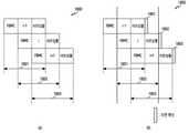
상기 도 18의 (a)를 참고하면, FBMC 시스템 1800은 FBMC 시스템의 이상적인 모델을 나타낸다. 이상적인 모델에서는 시구간 1801에 FBMC i-1 서브-심볼, 시구간 1802에 FBMC i 서브-심볼, 시구간 1803에 FBMC i+1 서브-심볼이 정확히 대응된다. 따라서 시구간 1802에서는 FBMC i-1 서브-심볼 뒷부분의 3분의 2, FBMC i 서브-심볼의 전체, FBMC i+1 서브-심볼 앞부분의 3분의 2를 수신할 수 있다.Referring to FIG. 18A , the
상기 도 18의 (b)를 참고하면, FBMC 시스템 1850은 FBMC 시스템의 실제적인 모델을 나타낸다. 실제적인 모델에서는 시구간 1851에 FBMC i-1 서브-심볼, 시구간 1852에 FBMC i 서브-심볼, 시구간 1853에 FBMC i+1 서브-심볼이 대응될 수 있다. 그러나 이상적인 모델과 달리, 각 서브-심볼마다 수신시간이 지연되는 지연확산(delay spread) 현상이 나타날 수 있다. FBMC i-1 서브-심볼은 지연확산 1861, FBMC i 서브-심볼은 지연확산 1862, FBMC i+1 서브-심볼은 지연확산 1863이 대응될 수 있다. 시구간 1802에서는 FBMC i-1 서브-심볼 뒷부분의 3분의 2, FBMC i 서브-심볼의 전체, FBMC i+1 서브-심볼 앞부분의 3분의 2 외에, 지연확산 1861을 같이 수신하게 될 수 있다. 이는 수신 신호로부터 송신 신호가 무엇인지 검출하기 어렵게 하는 요인이 될 수 있다. 지연확산의 영향이 큰 경우에 대응되는 시구간은 신뢰도가 높은 신호를 수신하기 어려울 수 있다. 신뢰도가 높지 않은 경우, 간섭의 영향을 정확하게 파악하기 어려울 뿐만 아니라 추가적으로 오류 확률을 높일 수 있다. 따라서 지연확산의 영향이 적은 순서로 검출순서를 결정해야 할 필요가 있을 수 있다.Referring to FIG. 18B , the
도 19는 일 실시 예에 따른, 지연확산을 고려하여 ML 검출을 수행하는 동작의 흐름도이다.19 is a flowchart of an operation of performing ML detection in consideration of delay spread, according to an embodiment.
상기 도 19를 참고하면, 1910 단계에서, 시간 도메인에서 지연확산(delay spread)의 영향이 적은 순서를 결정할 수 있다. FBMC 시스템의 경우, 캐리어 주파수 오프셋(carrier frequency offset, CFO)과 현재 채널의 시간의존도를 포함한 각 FBMC 서브-심볼의 유효 채널을 추정할 수 있다. 상기 각 FBMC 서브-심볼 유효 채널의 SIR을 측정하여, 지연확산이 발생한 지표로 사용할 수 있다.Referring to FIG. 19 , in
1920 단계에서, 검출영역의 크기를 결정한다. 상기 검출영역의 크기는 제1 검출영역의 크기일 수 있다. 다양한 실시 예에 따를 때, 상기 검출영역의 크기는 송신안테나들의 채널 이득, 지연확산의 영향, 채널의 상태, 필터의 특성, 신호의 변조 차수에 기반하여 결정될 수 있다.In
1930 단계에서, 상기 1910 단계에서 결정된 순서에 따라 ML 검출을 수행할 수 있다. 상기 1920 단계에서 결정된 검출영역의 크기를 단위로 ML 검출을 수행할 수 있다.In
다양한 실시 예에 따른 장치에 포함된 제어부는 신호의 지연확산(delay spread)의 정보에 기반하여 상기 제1 검출영역을 결정하도록 구성될 수 있다.The control unit included in the apparatus according to various embodiments may be configured to determine the first detection area based on information on delay spread of a signal.
도 20은 무선 통신 시스템에서 송신 안테나의 채널 이득을 도시한다.20 illustrates a channel gain of a transmit antenna in a wireless communication system.
상기 도 20을 참고하면, 상기 송신 안테나의 개수는 4개일 수 있다. 수신 안테나의 개수는 4개일 수 있다. 서브캐리어의 개수는 64개일 수 있다. 가로축은 서브캐리어의 인덱스를 나타낼 수 있고, 세로축은 송신 안테나의 채널 이득을 나타낼 수 있다. ML 검출 수행시, 검출 순서를 결정하는 경우, 안테나 도메인에 대하여 순서를 결정하는 것이 쉽지 않을 수 있다. 상기 도 20에 도시된 바와 같이, 안테나 4 (
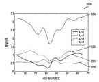
도 21a는 MIMO-OFDM 시스템에서, 다양한 실시 예에 따른 BER 성능과 기존 방식에 따른 BER 성능을 도시한 그래프이다. 이러한 상기 도 21a를 참고하면, 가로축은 잡음전력밀도에 대한 비트에너지의 비(


그래프 2110을 참고하면, 본 개시의 다양한 실시 예는 'Partial Candidate ML'에 대응될 수 있다. 상기 'Partial Candidate ML'은 캐리어들 마다 ML 검출을 수행하는 'per-tone ML'보다 확연히 더 나은 성능을 보일 수 있다. 동일한
도 21b는 MIMO-FBMC 시스템에서, 다양한 실시 예에 따른 BER 성능과 기존 방식에 따른 BER 성능을 도시한 그래프이다. 이러한 상기 도 21b를 참고하면, 가로축은 잡음전력밀도에 대한 비트에너지의 비(

그래프 2120을 참고하면, 본 개시의 다양한 실시 예는 'Partial Candidate ML'에 대응될 수 있다. 간섭 제거를 동반하는 'Rec-ML'에 비하여 큰 이득을 보인다. 'OFDM ML'과 비교시 BER 측면에서 동일한 성능을 나타낼 수 있다.Referring to
도 21c는 MIMO-OFDM 시스템에서, 순서 알고리즘의 적용 유무를 고려한, 다양한 실시 예에 따른 BER 성능과 기존 방식에 따른 BER 성능을 도시한 그래프이다. 이러한 상기 도 21c를 참고하면, 가로축은 잡음전력밀도에 대한 비트에너지의 비(

그래프 2130을 참고하면, 톤 별 선형 수신기(per-tone linear receiver)를 이용하여 찾은 신호들을 기반으로 본 개시의 다양한 실시 예에 따른 '부분 후보 ML(partial candidate ML)' 검출시 성능 이득이 매우 큼을 알 수 있다. 또한 순서를 정함으로써, '부분 후보 ML 검출 기법'의 성능이 개선될 수 있다.Referring to
도 22a는 MIMO-OFDM 시스템에서, 다양한 실시 예에 따른 BER 성능과 기존 방식에 따른 BER 성능을 도시한 그래프이다. 가로축은 잡음전력밀도에 대한 비트에너지의 비(

그래프 2210을 참고하면, 상기 도 21a와 비슷한 경향을 보일 수 있다. 'Per-tone ML'을 사용하는 경우, SIR을 보장받지 못해 에러 플로링(error flooring) 현상이 발생할 수 있다. 전술하였듯이, 최적의 'ML(w/0 CFO)'과 거의 근접한 BER성능을 보인다.Referring to the
도 22b는 MIMO-FBMC 시스템에서, 다양한 실시 예에 따른 BER 성능과 기존 방식에 따른 BER 성능을 도시한 그래프이다. 가로축은 잡음전력밀도에 대한 비트에너지의 비(

그래프 2220을 참고하면, 상기 도 21B와 비슷한 경향을 보일 수 있다. 그러나, 'OFDM ML'과 비교시 BER 측면에서 성능의 열화를 보일 수 있다. 이는 변조방식의 변조차수가 4에서 16으로 증가함에 따라 나타난 현상이라고 볼 수 있다. 본 개시의 다양한 실시 예에 따를 때, 상기 초기 검출결과와 상기 제3 검출결과의 구체적인 비교를 통해 재검출할 검출영역을 다시 결정하고, ML 검출을 다시 수행하여 최적화가 이루어질 수 있다.Referring to graph 2220, a similar trend to that of FIG. 21B may be shown. However, compared to 'OFDM ML', performance degradation may be observed in terms of BER. This can be seen as a phenomenon that appears as the modulation order of the modulation method increases from 4 to 16. According to various embodiments of the present disclosure, optimization may be achieved by re-determining a detection region to be re-detected through a detailed comparison between the initial detection result and the third detection result, and performing ML detection again.
도 23은 다양한 실시 예와 기존 방식에 따른 변조 차수에 대한 복잡도를 도시한다. 상기 도 23에서, 가로축은 변조 차수일 수 있고, 세로축은 복잡도일 수 있다. 'Banded ML'은 인근 캐리어간 간섭을 고려하기 위하여, 검출영역 주위까지 동시에 ML 검출을 수행하는 방식을 의미할 수 있다. 그러나 가능한 심볼군들의 수가 기하급수적으로 늘어나기 때문에 복잡도면에서 불리한 점을 가지고 있을 수 있다. 본 개시의 다양한 실시 예에 따른 '부분 후보 ML'은 상기 도 23에 도시된 바와 같이 복잡도면에서 기존의 'Per-tone ML'과 동일한 복잡도를 가지지만, 전술한 바와 같이 BER 성능면에 있어서 더 큰 이득을 보인다.23 is a diagram illustrating complexity of a modulation order according to various embodiments and a conventional method. In FIG. 23 , the horizontal axis may indicate a modulation order, and the vertical axis may indicate complexity. 'Banded ML' may refer to a method of simultaneously performing ML detection around a detection area in order to consider interference between adjacent carriers. However, since the number of possible symbol groups increases exponentially, it may have a disadvantage in terms of complexity. The 'partial candidate ML' according to various embodiments of the present disclosure has the same complexity as the conventional 'per-tone ML' in terms of complexity as shown in FIG. 23, but as described above, more in terms of BER performance show great benefits
상기와 같은 다양한 실시 예에 따른 장치의 동작 방법은, 송신 장치로부터 복수의 캐리어들을 통해 수신되는 신호에 기반하여 초기 검출결과를 생성하는 과정 채널 이득에 기반하여 상기 초기 검출결과에서 제1 검출영역을 결정하는 과정과, 가능한 심볼들을 상기 초기 검출결과의 상기 제1 검출영역에 삽입하여 제1 복수의 심볼군들을 생성하는 과정과, 상기 제1 복수의 심볼군들 중 최대 우도를 갖는 제1 심볼군에 기반하여 제1 검출결과를 생성하는 과정을 포함할 수 있다.In the method of operating an apparatus according to various embodiments as described above, a process of generating an initial detection result based on a signal received from a transmitting apparatus through a plurality of carriers. Based on a channel gain, a first detection area is selected from the initial detection result. determining; and inserting possible symbols into the first detection region of the initial detection result to generate a first plurality of symbol groups, and a first symbol group having a maximum likelihood among the first plurality of symbol groups. It may include a process of generating a first detection result based on the
상기와 같은 다양한 실시 예에 따른 장치의 동작 방법은 상기 초기 검출결과에서 상기 제1 검출영역에 대응하지 않는 제2 검출영역을 결정하는 과정과, 가능한 심볼들을 상기 제1 검출결과의 상기 제2 검출영역에 삽입하여 제2 복수의 심볼군들을 생성하는 과정과, 상기 제2 복수의 심볼군들 중 최대 우도를 갖는 제2 심볼군에 기반하여 제2 검출결과를 생성하는 과정을 더 포함할 수 있다.The method of operating the apparatus according to various embodiments as described above includes the steps of determining a second detection area that does not correspond to the first detection area from the initial detection result, and using possible symbols for the second detection of the first detection result. The method may further include generating a plurality of second symbol groups by inserting them into the region, and generating a second detection result based on a second symbol group having a maximum likelihood among the second plurality of symbol groups. .
상기와 같은 다양한 실시 예에 따른 장치의 동작 방법은 상기 초기 검출결과 및 상기 제2 검출결과에 기반하여 제3 검출영역을 결정하는 과정과, 가능한 심볼들을 상기 제2 검출결과의 상기 제3 검출영역에 삽입하여 제3 복수의 심볼군들을 생성하는 과정과, 상기 제3 복수의 심볼군들 중 최대 우도를 갖는 제3 심볼군에 기반하여 제3 검출결과를 생성하는 과정을 더 포함할 수 있다.The method of operating the apparatus according to various embodiments as described above includes the steps of determining a third detection area based on the initial detection result and the second detection result, and using possible symbols as the third detection area of the second detection result. The method may further include the steps of generating a plurality of third symbol groups by inserting them into , and generating a third detection result based on a third symbol group having a maximum likelihood among the plurality of third symbol groups.
상기 제 3 검출영역은 상기 초기 검출결과에서 상기 제2 검출결과에 대응하지 않는 검출영역일 수 있다. 또한 상기 제3 검출영역은 상기 수신되는 신호와 상기 초기 검출결과 사이의 유클리디안 거리(Euclidean distance) 및 상기 수신되는 신호와 상기 제1 검출결과 사이의 유클리디안 거리에 기반하여 결정될 수 있다. 또한 상기 제3 검출영역은 상기 복수의 캐리어들 중 적어도 하나의 캐리어의 채널 이득이 최대 우도를 갖는 심볼군 검출에 필요한 SIR(signal-to-interference ratio)의 평균값보다 작은 경우, 상기 적어도 하나의 캐리어에 대응될 수 있다.The third detection region may be a detection region that does not correspond to the second detection result in the initial detection result. In addition, the third detection region may be determined based on a Euclidean distance between the received signal and the initial detection result and a Euclidean distance between the received signal and the first detection result. In addition, the third detection area is the at least one carrier when the channel gain of at least one of the plurality of carriers is smaller than an average value of a signal-to-interference ratio (SIR) required for detecting a symbol group having the maximum likelihood. can correspond to
상기와 같은 다양한 실시 예에 따를 때, 상기 제1 검출영역은 상기 복수의 캐리어들 중 적어도 하나의 캐리어에 대응될 수 있다. 상기 적어도 하나의 캐리어는 상기 송신 장치에 포함된 안테나의 채널 이득의 크기에 기반하여 결정될 수 있다. 또한 상기 적어도 하나의 캐리어는 수신된 신호의 SIR 값에 따라 결정되고, 상기 SIR 값은 상기 송신 장치와 상기 수신 장치 간의 채널 상태 또는 필터의 특성 중 적어도 하나를 기반으로 측정되는 값일 수 있다. 또한 상기 제1 검출영역은 신호의 지연확산(delay spread)의 정도 또는 상기 신호의 변조 차수 중 적어도 어느 하나에 기반하여 결정될 수 있다.According to various embodiments as described above, the first detection area may correspond to at least one of the plurality of carriers. The at least one carrier may be determined based on a size of a channel gain of an antenna included in the transmitting apparatus. In addition, the at least one carrier is determined according to an SIR value of a received signal, and the SIR value may be a value measured based on at least one of a channel state between the transmitting device and the receiving device or a characteristic of a filter. Also, the first detection area may be determined based on at least one of a degree of delay spread of a signal or a modulation order of the signal.
상술한 본 개시의 구체적인 실시 예들에서, 개시에 포함되는 구성 요소는 제시된 구체적인 실시 예에 따라 단수 또는 복수로 표현되었다. 그러나, 단수 또는 복수의 표현은 설명의 편의를 위해 제시한 상황에 적합하게 선택된 것으로서, 본 개시가 단수 또는 복수의 구성 요소에 제한되는 것은 아니며, 복수로 표현된 구성 요소라 하더라도 단수로 구성되거나, 단수로 표현된 구성 요소라 하더라도 복수로 구성될 수 있다.In the specific embodiments of the present disclosure described above, elements included in the disclosure are expressed in the singular or plural according to the specific embodiments presented. However, the singular or plural expression is appropriately selected for the context presented for convenience of description, and the present disclosure is not limited to the singular or plural element, and even if the element is expressed in plural, it is composed of the singular or singular. Even an expressed component may be composed of a plurality of components.
한편 본 개시의 상세한 설명에서는 구체적인 실시 예에 관해 설명하였으나, 본 개시의 범위에서 벗어나지 않는 한도 내에서 여러 가지 변형이 가능함은 물론이다. 그러므로 본 개시의 범위는 설명된 실시 예에 국한되어 정해져서는 아니 되며 후술하는 특허청구의 범위뿐만 아니라 이 특허청구의 범위와 균등한 것들에 의해 정해져야 한다.Meanwhile, although specific embodiments have been described in the detailed description of the present disclosure, various modifications are possible without departing from the scope of the present disclosure. Therefore, the scope of the present disclosure should not be limited to the described embodiments and should be defined by the claims described below as well as the claims and equivalents.
Claims (20)
Translated fromKorean송신 장치로부터 복수의 캐리어들을 통해 수신되는 신호들에 기반하여 초기 검출 결과를 획득하는 과정;
상기 신호들 각각에 의해 측정된 상기 복수의 캐리어들 각각에 대한 채널 품질에 따라 상기 복수의 캐리어들 중 적어도 하나의 캐리어를 식별하는 과정;
상기 식별된 적어도 하나의 캐리어 및 상기 초기 검출 결과에 대응하는 제1 검출 영역과 관련된 가능한 심볼을 사용하여 상기 신호들에 대한 복수의 제1 심볼군들을 획득하는 과정;
상기 복수의 제1 심볼군들 중에서 최대 우도(maximum likelihood, ML)에 따라 식별된 상기 신호들에 대한 제1 심볼군에 기반하여 제1 검출 결과를 획득하는 과정; 및
상기 획득된 제1 검출 결과의 제2 검출 영역을 위한 ML 검출을 수행함으로써 상기 신호들의 제2 검출 결과를 획득하는 과정을 포함하고,
상기 제2 검출 영역은 상기 복수의 캐리어들 중 적어도 하나의 다른 캐리어에 대응하는 방법.
In the signal detection method of a receiving device,
obtaining an initial detection result based on signals received from a transmitting apparatus through a plurality of carriers;
identifying at least one of the plurality of carriers according to a channel quality for each of the plurality of carriers measured by each of the signals;
obtaining a plurality of first symbol groups for the signals using the identified at least one carrier and possible symbols associated with a first detection area corresponding to the initial detection result;
obtaining a first detection result based on a first symbol group for the signals identified according to a maximum likelihood (ML) among the plurality of first symbol groups; and
obtaining a second detection result of the signals by performing ML detection for a second detection region of the obtained first detection result;
and the second detection area corresponds to at least one other of the plurality of carriers.
상기 획득된 제1 검출 결과의 제2 검출 영역과 관련된 가능한 심볼을 사용하여 복수의 제2 심볼군들을 획득하는 과정; 및
상기 복수의 제2 심볼군들 중에서 ML에 따라 식별된 상기 신호들에 대한 제2 심볼군에 기반하여 상기 신호들의 제2 검출 결과를 획득하는 과정을 포함하는 방법.
The method according to claim 1, wherein the obtaining of the second detection result comprises:
obtaining a plurality of second symbol groups using possible symbols related to a second detection area of the obtained first detection result; and
and obtaining a second detection result of the signals based on a second symbol group for the signals identified according to ML among the plurality of second symbol groups.
상기 획득된 제2 검출 결과의 제3 검출 영역에 대한 ML 검출을 수행함으로써 제3 검출 결과를 획득하는 과정을 더 포함하고,
상기 제3 검출 영역은 복수의 캐리어들 중에서 적어도 하나의 후보 캐리어를 포함하고, 상기 적어도 하나의 후보 캐리어의 채널 품질은 ML에 따라 심볼군을 검출하기 위한 기준 채널 품질보다 작은 것을 특징으로 하는 방법.
The method according to claim 1,
The method further comprises: obtaining a third detection result by performing ML detection on a third detection region of the obtained second detection result;
The third detection area includes at least one candidate carrier from among a plurality of carriers, and the channel quality of the at least one candidate carrier is smaller than a reference channel quality for detecting a symbol group according to ML.
상기 복수의 캐리어들 각각에 대한 상기 송신 장치의 안테나들의 채널 이득들을 사용하여 결정되는 방법.
The method according to claim 1, wherein the channel quality for each of the plurality of carriers,
The method is determined using the channel gains of the antennas of the transmitting apparatus for each of the plurality of carriers.
상기 송신 장치와 상기 수신 장치 사이의 채널 상태에 기반하여 측정되는 방법.
The method according to claim 1, wherein the channel quality,
A method measured based on a channel state between the transmitting device and the receiving device.
상기 신호들 각각에 대한 지연 확산 정도에 기반하여 결정되는 방법.
The method according to claim 1, The number of the at least one carrier,
A method determined based on the degree of delay spread for each of the signals.
상기 적어도 하나의 다른 캐리어에 대한 제2 채널 품질 값보다 더 큰 방법.
The method according to claim 1, wherein the first channel quality value for the identified at least one carrier is:
greater than a second channel quality value for the at least one other carrier.
상기 복수의 캐리어들 각각을 통해 개별적으로 전송되는 방법.
The method according to claim 1, wherein each of the signals,
individually transmitted on each of the plurality of carriers.
상기 획득된 제2 검출 결과에서 제3 검출 영역에 대해 ML 검출을 수행함으로써, 상기 신호들의 제3 검출 결과를 획득하는 과정을 더 포함하고,
상기 제3 검출 영역은 상기 제2 검출 결과와 상기 초기 검출 결과의 차이에 기반하여 결정되는 방법.
The method according to claim 1,
The method further comprises: obtaining a third detection result of the signals by performing ML detection on a third detection region in the obtained second detection result;
The third detection area is determined based on a difference between the second detection result and the initial detection result.
상기 획득된 제2 검출 결과의 제3 검출 영역과 관련된 가능한 심볼을 사용하여 복수의 제3 심볼군들을 획득하는 과정; 및
상기 복수의 제3 심볼군들 중에서 식별된 상기 신호들에 대한 제3 심볼군에 기반하여 상기 신호들의 제3 검출 결과를 획득하는 과정을 포함하는 방법.
The method of claim 9, wherein the obtaining of the third detection result comprises:
obtaining a plurality of third symbol groups by using possible symbols related to a third detection region of the obtained second detection result; and
and obtaining a third detection result of the signals based on a third symbol group for the signals identified from among the plurality of third symbol groups.
적어도 하나의 트랜시버(transceiver); 및
상기 적어도 하나의 트랜시버와 기능적으로 결합된 적어도 하나의 프로세서(processor)를 포함하고,
상기 적어도 하나의 프로세서는,
송신 장치로부터 복수의 캐리어들을 통해 수신되는 신호들에 기반하여 초기 검출 결과를 획득하고,
상기 신호들 각각에 의해 측정된 상기 복수의 캐리어들 각각에 대한 채널 품질에 따라 상기 복수의 캐리어들 중 적어도 하나의 캐리어를 식별하고,
상기 식별된 적어도 하나의 캐리어 및 상기 초기 검출 결과에 대응하는 제1 검출 영역과 관련된 가능한 심볼을 사용하여 상기 신호들에 대한 복수의 제1 심볼군들을 획득하고,
상기 복수의 제1 심볼군들 중에서 최대 우도(maximum likelihood, ML)에 따라 식별된 상기 신호들에 대한 제1 심볼군에 기반하여 제1 검출 결과를 획득하고, 및
상기 획득된 제1 검출 결과의 제2 검출 영역을 위한 ML 검출을 수행함으로써 상기 신호들의 제2 검출 결과를 획득하도록 구성되고,
상기 제2 검출 영역은 복수의 캐리어들 중 적어도 하나의 다른 캐리어에 대응하도록 구성되는 수신 장치.
A receiving device for detecting a signal, comprising:
at least one transceiver; and
at least one processor operatively coupled to the at least one transceiver;
The at least one processor,
Obtaining an initial detection result based on signals received through a plurality of carriers from the transmitting device,
identify at least one of the plurality of carriers according to a channel quality for each of the plurality of carriers measured by each of the signals;
obtaining a plurality of first symbol groups for the signals using the identified at least one carrier and possible symbols associated with a first detection area corresponding to the initial detection result;
obtaining a first detection result based on a first symbol group for the signals identified according to a maximum likelihood (ML) among the plurality of first symbol groups; and
and obtain a second detection result of the signals by performing ML detection for a second detection area of the obtained first detection result,
The second detection area is configured to correspond to at least one other carrier among the plurality of carriers.
상기 획득된 제1 검출 결과의 제2 검출 영역과 관련된 가능한 심볼을 사용하여 복수의 제2 심볼군들을 획득하고, 및
상기 복수의 제2 심볼군들 중에서 ML에 따라 식별된 상기 신호들에 대한 제2 심볼군에 기반하여 상기 신호들의 제2 검출 결과를 획득하도록 구성되는 수신 장치.
The method of claim 11 , wherein to obtain the second detection result, the at least one processor comprises:
obtaining a plurality of second symbol groups by using possible symbols associated with a second detection area of the obtained first detection result, and
and obtain a second detection result of the signals based on a second symbol group for the signals identified according to ML among the plurality of second symbol groups.
상기 획득된 제2 검출 결과의 제3 검출 영역에 대한 ML 검출을 수행함으로써 제3 검출 결과를 획득하도록 더 구성되고,
상기 제3 검출 영역은 복수의 캐리어들 중에서 적어도 하나의 후보 캐리어를 포함하고, 상기 적어도 하나의 후보 캐리어의 채널 품질은 ML에 따라 심볼군을 검출하기 위한 기준 채널 품질보다 작도록 구성되는 수신 장치.
The method of claim 11 , wherein the at least one processor comprises:
further configured to obtain a third detection result by performing ML detection on a third detection region of the obtained second detection result,
The third detection area includes at least one candidate carrier from among a plurality of carriers, and the channel quality of the at least one candidate carrier is configured to be smaller than a reference channel quality for detecting a symbol group according to ML.
상기 복수의 캐리어들 각각에 대한 상기 송신 장치의 안테나들의 채널 이득들을 사용하여 결정되도록 구성되는 수신 장치.
The method according to claim 11, wherein the channel quality for each of the plurality of carriers,
and the receiving apparatus is configured to be determined using channel gains of the antennas of the transmitting apparatus for each of the plurality of carriers.
상기 송신 장치와 상기 수신 장치 사이의 채널 상태에 기초하여 측정되도록 구성되는 수신 장치.
The method according to claim 11, wherein the channel quality,
a receiving device configured to be measured based on a channel condition between the transmitting device and the receiving device.
상기 신호들 각각에 대한 지연 확산 정도에 기반하여 결정되도록 구성되는 수신 장치.
The method according to claim 11, wherein the number of the at least one carrier,
and a receiving device configured to be determined based on a degree of delay spread for each of the signals.
상기 적어도 하나의 다른 캐리어에 대한 제2 채널 품질 값보다 크도록 구성되는 수신 장치.
12. The method of claim 11, wherein the first channel quality value for the identified at least one carrier comprises:
and a second channel quality value for the at least one other carrier.
상기 복수의 캐리어들 각각을 통해 개별적으로 전송되도록 구성되는 수신 장치.
The method according to claim 11, wherein each of the signals,
A receiving device configured to be transmitted individually on each of the plurality of carriers.
상기 획득된 제2 검출 결과에서 제3 검출 영역에 대해 ML 검출을 수행함으로써, 상기 신호들의 제3 검출 결과를 획득하도록 더 구성되고,
상기 제3 검출 영역은 상기 제2 검출 결과와 상기 초기 검출 결과의 차이에 기반하여 결정되도록 구성되는 수신 장치.
The method of claim 11 , wherein the at least one processor comprises:
further configured to obtain a third detection result of the signals by performing ML detection on a third detection area in the obtained second detection result,
and the third detection area is configured to be determined based on a difference between the second detection result and the initial detection result.
상기 획득된 제2 검출 결과의 제3 검출 영역과 관련된 가능한 심볼을 사용하여 복수의 제3 심볼군들을 획득하고, 및
상기 복수의 제3 심볼군들 중에서 식별된 상기 신호들에 대한 제3 심볼군에 기반하여 상기 신호들의 제3 검출 결과를 획득하도록 구성되는 수신 장치.
20. The method of claim 19, wherein to obtain the third detection result, the at least one processor comprises:
obtaining a plurality of third symbol groups by using possible symbols associated with a third detection region of the obtained second detection result, and
and obtain a third detection result of the signals based on a third symbol group for the signals identified from among the plurality of third symbol groups.
Priority Applications (2)
| Application Number | Priority Date | Filing Date | Title |
|---|---|---|---|
| KR1020150161327AKR102370119B1 (en) | 2015-11-17 | 2015-11-17 | Apparatus and method for detecting signals based on partial candidate in wireless communication system |
| US15/354,945US10051631B2 (en) | 2015-11-17 | 2016-11-17 | Apparatus and method for detecting signals based on partial candidate in wireless communication system |
Applications Claiming Priority (1)
| Application Number | Priority Date | Filing Date | Title |
|---|---|---|---|
| KR1020150161327AKR102370119B1 (en) | 2015-11-17 | 2015-11-17 | Apparatus and method for detecting signals based on partial candidate in wireless communication system |
Publications (2)
| Publication Number | Publication Date |
|---|---|
| KR20170057764A KR20170057764A (en) | 2017-05-25 |
| KR102370119B1true KR102370119B1 (en) | 2022-03-04 |
Family
ID=58691747
Family Applications (1)
| Application Number | Title | Priority Date | Filing Date |
|---|---|---|---|
| KR1020150161327AActiveKR102370119B1 (en) | 2015-11-17 | 2015-11-17 | Apparatus and method for detecting signals based on partial candidate in wireless communication system |
Country Status (2)
| Country | Link |
|---|---|
| US (1) | US10051631B2 (en) |
| KR (1) | KR102370119B1 (en) |
Families Citing this family (6)
| Publication number | Priority date | Publication date | Assignee | Title |
|---|---|---|---|---|
| CN104065461B (en)* | 2013-03-22 | 2017-08-25 | 华为技术有限公司 | Signaling method and apparatus for transmitting signal |
| KR102221951B1 (en)* | 2014-07-18 | 2021-03-04 | 삼성전자 주식회사 | Layered detection method and apparatus for qam-fbmc system |
| US10084582B2 (en)* | 2016-12-22 | 2018-09-25 | Qualcomm Incorporated | Techniques for signaling dynamic control region for PRACH transmission |
| US10292160B1 (en)* | 2017-02-17 | 2019-05-14 | Sprint Spectrum L.P. | Prioritizing uplink grants to mobile devices assigned to frequencies subject to group delay variation |
| US10790929B2 (en)* | 2018-10-12 | 2020-09-29 | Samsung Electronics Co., Ltd. | Nested lookup table for symbol detection with initial candidate reduction |
| KR102562314B1 (en) | 2018-11-02 | 2023-08-01 | 삼성전자주식회사 | Multiple input multiple output receiver for selecting candidate vector set and method of operation thereof |
Citations (2)
| Publication number | Priority date | Publication date | Assignee | Title |
|---|---|---|---|---|
| US20130243062A1 (en)* | 2012-03-16 | 2013-09-19 | Posedge Inc. | Receive Signal Detection of Multi-Carrier Signals |
| US20150078490A1 (en)* | 2013-09-19 | 2015-03-19 | Huawei Technologies Co., Ltd. | Methods and user equipment in a wireless communication network |
Family Cites Families (23)
| Publication number | Priority date | Publication date | Assignee | Title |
|---|---|---|---|---|
| US5351274A (en)* | 1993-08-20 | 1994-09-27 | General Electric Company | Post detection selection combining diversity receivers for mobile and indoor radio channels |
| KR100630108B1 (en)* | 2002-10-10 | 2006-09-27 | 삼성전자주식회사 | Transmitting and receiving apparatus for supporting transmission antenna diversity using space-time block code |
| EP1564908A1 (en)* | 2003-12-23 | 2005-08-17 | Telefonaktiebolaget LM Ericsson (publ) | Advanced multi-sensor processing |
| US7433432B2 (en)* | 2004-12-31 | 2008-10-07 | Broadcom Corporation | Adaptive detector for multiple-data-path systems |
| JP2006287756A (en)* | 2005-04-01 | 2006-10-19 | Ntt Docomo Inc | Transmission device, transmission method, reception device, and reception method |
| EP2014039A1 (en)* | 2006-05-04 | 2009-01-14 | Agency for Science, Technology and Research | Method and system for determining a signal vector |
| TW200812270A (en)* | 2006-08-31 | 2008-03-01 | Interdigital Tech Corp | Method and apparatus for QR decomposition-based MIMO detection and soft bit generation |
| US20080267306A1 (en)* | 2007-04-27 | 2008-10-30 | Texas Instruments Incorporated | Systems and Methods for Low-Complexity Maximum-Likelihood MIMO Detection |
| FR2927206B1 (en)* | 2008-02-04 | 2014-02-14 | Groupe Des Ecoles De Telecommunications Get Ecole Nationale Superieure Des Telecommunications Enst | METHOD OF DECODING A SIGNAL TRANSMITTED IN A MULTI-ANTENNA SYSTEM, COMPUTER PROGRAM PRODUCT AND CORRESPONDING DECODING DEVICE |
| WO2009113105A2 (en)* | 2008-02-29 | 2009-09-17 | Indian Institute Of Science | A method to detect data transmitted by multiple antennas |
| EP2263356B1 (en)* | 2008-03-07 | 2016-09-21 | Imec | Mimo sphere detection with parallel distributed node processing |
| US8351549B1 (en)* | 2008-10-02 | 2013-01-08 | Marvell International Ltd. | Multi-stream demodulation scheme using multiple detectors |
| KR101026021B1 (en)* | 2009-09-16 | 2011-03-30 | 포항공과대학교 산학협력단 | Method and apparatus for detecting space-time block codes |
| US8300737B2 (en)* | 2009-10-07 | 2012-10-30 | Research In Motion Limited | System and method for MIMO decoding |
| KR101043698B1 (en)* | 2009-10-21 | 2011-06-24 | 중앙대학교 산학협력단 | Signal Detection Device and Method in Spatial Multiplexing System |
| TW201141427A (en)* | 2010-05-21 | 2011-12-01 | Jing Zhan Biotechnology Co Ltd | Pneumatic device with comfortable sleep effect |
| US8767657B1 (en)* | 2011-04-19 | 2014-07-01 | Quantenna Communications Inc. | Mixed-mode MIMO detector in a local area network |
| EP2706684B1 (en)* | 2012-09-10 | 2018-11-07 | MStar Semiconductor, Inc | Apparatus for MIMO channel performance prediction |
| US8908743B2 (en)* | 2012-09-26 | 2014-12-09 | Intel Mobile Communications GmbH | Receiver with multi layer interference cancellation |
| US9008240B1 (en)* | 2013-12-31 | 2015-04-14 | Cambridge Silicon Radio Limited | Near maximum likelihood spatial multiplexing receiver |
| US9083499B1 (en)* | 2013-12-31 | 2015-07-14 | Cambridge Silicon Radio Limited | Decision feedback solution for channels with low signal to noise ratio |
| KR20150117155A (en)* | 2014-04-09 | 2015-10-19 | 한국전자통신연구원 | Method and apparatus for soft detecting multiple-input multiple-output communication system |
| US9942004B2 (en)* | 2015-06-15 | 2018-04-10 | Ching-Yih Tseng | Apparatus and methods for maximum likelihood symbol detection in communications systems |
- 2015
- 2015-11-17KRKR1020150161327Apatent/KR102370119B1/enactiveActive
- 2016
- 2016-11-17USUS15/354,945patent/US10051631B2/enactiveActive
Patent Citations (2)
| Publication number | Priority date | Publication date | Assignee | Title |
|---|---|---|---|---|
| US20130243062A1 (en)* | 2012-03-16 | 2013-09-19 | Posedge Inc. | Receive Signal Detection of Multi-Carrier Signals |
| US20150078490A1 (en)* | 2013-09-19 | 2015-03-19 | Huawei Technologies Co., Ltd. | Methods and user equipment in a wireless communication network |
Also Published As
| Publication number | Publication date |
|---|---|
| US10051631B2 (en) | 2018-08-14 |
| US20170142726A1 (en) | 2017-05-18 |
| KR20170057764A (en) | 2017-05-25 |
Similar Documents
| Publication | Publication Date | Title |
|---|---|---|
| KR102370119B1 (en) | Apparatus and method for detecting signals based on partial candidate in wireless communication system | |
| KR102282868B1 (en) | Method and apparatus for channel estimation in wireless communication system | |
| CN102882575B (en) | For determining the method and apparatus of channel condition information | |
| CN103873080B (en) | Receiver, receiver circuits, and methods for providing an interference-reduced signal | |
| Nikitopoulos et al. | Geosphere: Consistently turning MIMO capacity into throughput | |
| KR102318817B1 (en) | Apparatus and method for pre-preocessing for filter bank multicarrier scheme in wireless communication system | |
| US9654252B2 (en) | Low complexity maximum-likelihood-based method for estimating emitted symbols in a SM-MIMO receiver | |
| KR20130011294A (en) | Apparatus and method for beam-forming in a multi input multi output | |
| JP2012514421A (en) | Method and system for co-channel interference cancellation in wireless networks | |
| CN107113075A (en) | Method and arrangement for receiving signals based on interference measurements in a mobile communication system | |
| KR20190073343A (en) | Data transmission and reception in a wireless communication network using a combination of real modulation type and complex modulation type | |
| US8625697B2 (en) | OFDM beamformer, and a signal receiving system incorporating the same | |
| US9871686B2 (en) | Method and apparatus for transmitting and receiving signal using variable observation length in multicarrier system using non-orthogonal transmission signal | |
| KR20140112931A (en) | Method and Apparatus for Detection Soft-Decision in 2X2 MIMO Systems | |
| US10237010B2 (en) | Method and apparatus of constructing interference component and estimating channel for multicarrier systems with non-orthogonal waveform | |
| Mao et al. | Filtered OFDM: An insight into intrinsic in-band interference and filter frequency response selectivity | |
| KR101237452B1 (en) | Methods and systems for hybrid mimo schemes in ofdm/a systems | |
| CN109167748B (en) | Partial maximum likelihood detection method based on energy sorting | |
| US20170272281A1 (en) | Method and apparatus for attenuating interference or cancelling interference in filter bank multicarrier system | |
| US12284128B2 (en) | Device and method for detecting interference between base stations in wireless communication system | |
| JP2006211131A (en) | Receiver and receiving method | |
| KR100888061B1 (en) | Transmission Power Allocation Method for Improving Bit Error Rate Performance of Multiple Input Multiple Output Orthogonal Frequency Division Multiplexing Systems | |
| RU2405254C2 (en) | Evaluation method of data transmission channel in wireless communication system (versions) | |
| KR102857564B1 (en) | Apparatus and method for detecting interference between base stations in wireless communication system | |
| CN110868716A (en) | A Physical Layer Security Algorithm Based on Consecutive Subcarrier Grouping |
Legal Events
| Date | Code | Title | Description |
|---|---|---|---|
| PA0109 | Patent application | Patent event code:PA01091R01D Comment text:Patent Application Patent event date:20151117 | |
| PG1501 | Laying open of application | ||
| A201 | Request for examination | ||
| PA0201 | Request for examination | Patent event code:PA02012R01D Patent event date:20200826 Comment text:Request for Examination of Application Patent event code:PA02011R01I Patent event date:20151117 Comment text:Patent Application | |
| E902 | Notification of reason for refusal | ||
| PE0902 | Notice of grounds for rejection | Comment text:Notification of reason for refusal Patent event date:20210702 Patent event code:PE09021S01D | |
| E701 | Decision to grant or registration of patent right | ||
| PE0701 | Decision of registration | Patent event code:PE07011S01D Comment text:Decision to Grant Registration Patent event date:20220103 | |
| GRNT | Written decision to grant | ||
| PR0701 | Registration of establishment | Comment text:Registration of Establishment Patent event date:20220228 Patent event code:PR07011E01D | |
| PR1002 | Payment of registration fee | Payment date:20220302 End annual number:3 Start annual number:1 | |
| PG1601 | Publication of registration | ||
| PR1001 | Payment of annual fee | Payment date:20250124 Start annual number:4 End annual number:4 |