KR102369852B1 - Apparatus and method for laser processing materials - Google Patents
Apparatus and method for laser processing materialsDownload PDFInfo
- Publication number
- KR102369852B1 KR102369852B1KR1020197005778AKR20197005778AKR102369852B1KR 102369852 B1KR102369852 B1KR 102369852B1KR 1020197005778 AKR1020197005778 AKR 1020197005778AKR 20197005778 AKR20197005778 AKR 20197005778AKR 102369852 B1KR102369852 B1KR 102369852B1
- Authority
- KR
- South Korea
- Prior art keywords
- optical fiber
- squeezing
- squeezing mechanism
- pitch
- mode
- Prior art date
- Legal status (The legal status is an assumption and is not a legal conclusion. Google has not performed a legal analysis and makes no representation as to the accuracy of the status listed.)
- Active
Links
- 239000000463materialSubstances0.000titleclaimsabstract11
- 238000000034methodMethods0.000titleclaims17
- 230000007246mechanismEffects0.000claimsabstract37
- 239000013307optical fiberSubstances0.000claimsabstract37
- 230000000737periodic effectEffects0.000claimsabstract19
- 230000005855radiationEffects0.000claimsabstract16
- 230000003287optical effectEffects0.000claims18
- 230000001902propagating effectEffects0.000claims4
- 230000008878couplingEffects0.000claims1
- 238000010168coupling processMethods0.000claims1
- 238000005859coupling reactionMethods0.000claims1
- 239000011521glassSubstances0.000claims1
- NJPPVKZQTLUDBO-UHFFFAOYSA-NnovaluronChemical compoundC1=C(Cl)C(OC(F)(F)C(OC(F)(F)F)F)=CC=C1NC(=O)NC(=O)C1=C(F)C=CC=C1FNJPPVKZQTLUDBO-UHFFFAOYSA-N0.000claims1
- 230000007704transitionEffects0.000claims1
Images


Classifications
- B—PERFORMING OPERATIONS; TRANSPORTING
- B23—MACHINE TOOLS; METAL-WORKING NOT OTHERWISE PROVIDED FOR
- B23K—SOLDERING OR UNSOLDERING; WELDING; CLADDING OR PLATING BY SOLDERING OR WELDING; CUTTING BY APPLYING HEAT LOCALLY, e.g. FLAME CUTTING; WORKING BY LASER BEAM
- B23K26/00—Working by laser beam, e.g. welding, cutting or boring
- B23K26/36—Removing material
- B23K26/38—Removing material by boring or cutting
- G—PHYSICS
- G02—OPTICS
- G02B—OPTICAL ELEMENTS, SYSTEMS OR APPARATUS
- G02B6/00—Light guides; Structural details of arrangements comprising light guides and other optical elements, e.g. couplings
- G02B6/24—Coupling light guides
- G02B6/26—Optical coupling means
- B—PERFORMING OPERATIONS; TRANSPORTING
- B23—MACHINE TOOLS; METAL-WORKING NOT OTHERWISE PROVIDED FOR
- B23K—SOLDERING OR UNSOLDERING; WELDING; CLADDING OR PLATING BY SOLDERING OR WELDING; CUTTING BY APPLYING HEAT LOCALLY, e.g. FLAME CUTTING; WORKING BY LASER BEAM
- B23K26/00—Working by laser beam, e.g. welding, cutting or boring
- B23K26/02—Positioning or observing the workpiece, e.g. with respect to the point of impact; Aligning, aiming or focusing the laser beam
- B23K26/06—Shaping the laser beam, e.g. by masks or multi-focusing
- B23K26/064—Shaping the laser beam, e.g. by masks or multi-focusing by means of optical elements, e.g. lenses, mirrors or prisms
- B23K26/0648—Shaping the laser beam, e.g. by masks or multi-focusing by means of optical elements, e.g. lenses, mirrors or prisms comprising lenses
- B—PERFORMING OPERATIONS; TRANSPORTING
- B23—MACHINE TOOLS; METAL-WORKING NOT OTHERWISE PROVIDED FOR
- B23K—SOLDERING OR UNSOLDERING; WELDING; CLADDING OR PLATING BY SOLDERING OR WELDING; CUTTING BY APPLYING HEAT LOCALLY, e.g. FLAME CUTTING; WORKING BY LASER BEAM
- B23K26/00—Working by laser beam, e.g. welding, cutting or boring
- B23K26/02—Positioning or observing the workpiece, e.g. with respect to the point of impact; Aligning, aiming or focusing the laser beam
- B23K26/06—Shaping the laser beam, e.g. by masks or multi-focusing
- B23K26/0665—Shaping the laser beam, e.g. by masks or multi-focusing by beam condensation on the workpiece, e.g. for focusing
- B—PERFORMING OPERATIONS; TRANSPORTING
- B23—MACHINE TOOLS; METAL-WORKING NOT OTHERWISE PROVIDED FOR
- B23K—SOLDERING OR UNSOLDERING; WELDING; CLADDING OR PLATING BY SOLDERING OR WELDING; CUTTING BY APPLYING HEAT LOCALLY, e.g. FLAME CUTTING; WORKING BY LASER BEAM
- B23K26/00—Working by laser beam, e.g. welding, cutting or boring
- B23K26/02—Positioning or observing the workpiece, e.g. with respect to the point of impact; Aligning, aiming or focusing the laser beam
- B23K26/06—Shaping the laser beam, e.g. by masks or multi-focusing
- B23K26/073—Shaping the laser spot
- B—PERFORMING OPERATIONS; TRANSPORTING
- B23—MACHINE TOOLS; METAL-WORKING NOT OTHERWISE PROVIDED FOR
- B23K—SOLDERING OR UNSOLDERING; WELDING; CLADDING OR PLATING BY SOLDERING OR WELDING; CUTTING BY APPLYING HEAT LOCALLY, e.g. FLAME CUTTING; WORKING BY LASER BEAM
- B23K26/00—Working by laser beam, e.g. welding, cutting or boring
- B23K26/08—Devices involving relative movement between laser beam and workpiece
- B23K26/0869—Devices involving movement of the laser head in at least one axial direction
- B23K26/0876—Devices involving movement of the laser head in at least one axial direction in at least two axial directions
- B—PERFORMING OPERATIONS; TRANSPORTING
- B23—MACHINE TOOLS; METAL-WORKING NOT OTHERWISE PROVIDED FOR
- B23K—SOLDERING OR UNSOLDERING; WELDING; CLADDING OR PLATING BY SOLDERING OR WELDING; CUTTING BY APPLYING HEAT LOCALLY, e.g. FLAME CUTTING; WORKING BY LASER BEAM
- B23K26/00—Working by laser beam, e.g. welding, cutting or boring
- B23K26/14—Working by laser beam, e.g. welding, cutting or boring using a fluid stream, e.g. a jet of gas, in conjunction with the laser beam; Nozzles therefor
- B23K26/142—Working by laser beam, e.g. welding, cutting or boring using a fluid stream, e.g. a jet of gas, in conjunction with the laser beam; Nozzles therefor for the removal of by-products
- B—PERFORMING OPERATIONS; TRANSPORTING
- B23—MACHINE TOOLS; METAL-WORKING NOT OTHERWISE PROVIDED FOR
- B23K—SOLDERING OR UNSOLDERING; WELDING; CLADDING OR PLATING BY SOLDERING OR WELDING; CUTTING BY APPLYING HEAT LOCALLY, e.g. FLAME CUTTING; WORKING BY LASER BEAM
- B23K26/00—Working by laser beam, e.g. welding, cutting or boring
- B23K26/20—Bonding
- B—PERFORMING OPERATIONS; TRANSPORTING
- B23—MACHINE TOOLS; METAL-WORKING NOT OTHERWISE PROVIDED FOR
- B23K—SOLDERING OR UNSOLDERING; WELDING; CLADDING OR PLATING BY SOLDERING OR WELDING; CUTTING BY APPLYING HEAT LOCALLY, e.g. FLAME CUTTING; WORKING BY LASER BEAM
- B23K26/00—Working by laser beam, e.g. welding, cutting or boring
- B23K26/34—Laser welding for purposes other than joining
- B—PERFORMING OPERATIONS; TRANSPORTING
- B23—MACHINE TOOLS; METAL-WORKING NOT OTHERWISE PROVIDED FOR
- B23K—SOLDERING OR UNSOLDERING; WELDING; CLADDING OR PLATING BY SOLDERING OR WELDING; CUTTING BY APPLYING HEAT LOCALLY, e.g. FLAME CUTTING; WORKING BY LASER BEAM
- B23K26/00—Working by laser beam, e.g. welding, cutting or boring
- B23K26/70—Auxiliary operations or equipment
- B23K26/702—Auxiliary equipment
- G—PHYSICS
- G02—OPTICS
- G02B—OPTICAL ELEMENTS, SYSTEMS OR APPARATUS
- G02B27/00—Optical systems or apparatus not provided for by any of the groups G02B1/00 - G02B26/00, G02B30/00
- G02B27/48—Laser speckle optics
- G—PHYSICS
- G02—OPTICS
- G02B—OPTICAL ELEMENTS, SYSTEMS OR APPARATUS
- G02B6/00—Light guides; Structural details of arrangements comprising light guides and other optical elements, e.g. couplings
- G02B6/02—Optical fibres with cladding with or without a coating
- G02B6/02042—Multicore optical fibres
- G—PHYSICS
- G02—OPTICS
- G02B—OPTICAL ELEMENTS, SYSTEMS OR APPARATUS
- G02B6/00—Light guides; Structural details of arrangements comprising light guides and other optical elements, e.g. couplings
- G02B6/02—Optical fibres with cladding with or without a coating
- G02B6/02057—Optical fibres with cladding with or without a coating comprising gratings
- G02B6/02071—Mechanically induced gratings, e.g. having microbends
Landscapes
- Physics & Mathematics (AREA)
- Optics & Photonics (AREA)
- Engineering & Computer Science (AREA)
- Plasma & Fusion (AREA)
- Mechanical Engineering (AREA)
- General Physics & Mathematics (AREA)
- Laser Beam Processing (AREA)
- Light Guides In General And Applications Therefor (AREA)
Abstract
Translated fromKoreanDescription
Translated fromKorean본 발명은 재료를 레이저 프로세싱하기 위한 장치 및 방법에 관한 것이다.The present invention relates to an apparatus and method for laser processing a material.
강(steel)의 레이저 절삭(laser cutting)은, 레이저 빔과 동축(co-axial)인 고압 가스 제트를 제공하기 위한 원뿔형 구리 노즐 및 레이저 빔을 콜리메이팅(collimating) 및 포커싱하기 위한 광학계(optics)를 갖는 프로세스 헤드를 통해 레이저 빔을 피가공물(work-piece)에 지향시키는 것에 의해 달성된다. 기본 절삭 동작은, 레이저 빔이 금속판 피가공물을 가열 및 용융하는 것, 그리고 보조 가스 제트라고 알려져 있는 가스 제트가 용융된 재료를 절삭 존(cut-zone)의 저부 밖으로 분출시키는 것을 수반한다. 절삭 헤드는 노즐 팁과 피가공물 표면 사이의 일정한 거리를 유지하면서 판금(sheet metal) 위로 이동된다. 절삭 헤드는 프로그래밍된 경로에서 이동되어, 요망되는 판금 프로파일을 생성한다.Laser cutting of steel involves a conical copper nozzle to provide a high-pressure gas jet co-axial with the laser beam and optics for collimating and focusing the laser beam. It is achieved by directing a laser beam at a work-piece through a process head with The basic cutting operation involves a laser beam heating and melting a sheet metal workpiece, and a gas jet known as an auxiliary gas jet ejects the molten material out of the bottom of a cut-zone. The cutting head is moved over the sheet metal maintaining a constant distance between the nozzle tip and the workpiece surface. The cutting head is moved in a programmed path to create the desired sheet metal profile.
스테인리스 강을 절삭하는 경우에는, 불활성 보조 가스를 사용하는 것이 전형적이다. 이것은 금속 부분이 사용 중일 때 문제들을 야기시킬 수 있는 피가공물의 절삭-에지 면들 상의 금속 산화물들의 생성을 방지한다. 이 절삭 프로세스를 위한 유일한 열원이 포커싱된 레이저 빔에 의해 제공되기 때문에, 보다 높은 에너지 전력 밀도를 갖는 보다 작은 초점 스폿 사이즈는 보다 좁은 용융된 영역을 생성하는 것에 의해 더 효율적인 절삭을 제공할 것이다. 용융 영역이 금속의 두께를 통해 좁아지도록 낮은 발산(divergence)을 사용하는 것이 이롭다. 가장 작은 실제적인 초점 스폿에 대한 한계는 재료 두께와 관련하여 광학 피사계 심도에 의해 결정된다. 이것은 절삭-폭(커프(kerf))이 보조 가스가 충분한 압력으로 절삭의 저부로 이동하게 하여 용융된 재료를 깨끗하게 제거하고 보다 낮은 절삭 에지 상의 드로스(dross)를 회피하여 깨끗한 절삭을 생성하기에 충분히 넓어야 하기 때문이다. 이 절삭 타입의 경우, 보조 가스는, 전형적으로 10 내지 20 bar의 범위에서의, 높은 압력으로 제공되어야 한다. 노즐 유출구의 직경은 통상적으로 범위 0.5 ㎜ 내지 2.0 ㎜에 있고, 일반적으로 보다 두꺼운 재료들이 보다 큰 노즐들을 요구한다.When cutting stainless steel, it is typical to use an inert auxiliary gas. This prevents the formation of metal oxides on the cutting-edge faces of the workpiece, which can cause problems when the metal part is in use. Since the only heat source for this cutting process is provided by the focused laser beam, a smaller focal spot size with a higher energy power density will provide more efficient cutting by creating a narrower molten area. It is advantageous to use low divergence so that the melting zone narrows through the thickness of the metal. The limit for the smallest practical focal spot is determined by the optical depth of field in relation to the material thickness. This is because the cut-width (kerf) allows the assist gas to travel to the bottom of the cut with sufficient pressure to cleanly remove the molten material and avoid dross on the lower cutting edge to create a clean cut. It has to be wide enough. For this cutting type, the auxiliary gas has to be provided at high pressure, typically in the range of 10 to 20 bar. The diameter of the nozzle outlet typically ranges from 0.5 mm to 2.0 mm, with generally thicker materials requiring larger nozzles.
5 ㎜보다 더 두꺼운 연강(mild steel)(저탄소 강이라고도 또한 알려져 있음)을 절삭하는 경우에, 피가공물 내의 철과 발열 반응하여 절삭 속도를 증가시키는 부가적인 열을 제공하는 산소를 보조 가스로서 사용하는 것이 전형적이다. 이것은 전형적으로 범위 0.25 bar 내지 1 bar에서의 압력들로 제공되는데, 이 범위는 질소 보조 가스 절삭에 사용되는 것에 비해 훨씬 더 낮다. 전형적으로 범위 10 ㎜ 내지 30 ㎜ 두께에서의, 두꺼운 단면 절삭의 경우, 드로스가 없는 절삭을 유지하면서 용융된 재료를 방출하기에 충분한 가스 흐름으로 산소 보조 가스가 절삭 존의 저부에 도달할 수 있도록 커프가 충분히 넓어야 한다. 두꺼운 연강 절삭을 위해, 판금 표면 상의 입사 빔 직경이 빔 허리보다 더 커지도록 빔 허리가 판금 표면 위에 있도록 빔이 디포커싱되는 것이 통상적이다. 빔의 발산이 증가될 때 보다 낮은 에지 거칠기를 갖는 보다 양호한 품질의 절삭들이 획득될 수 있다.When cutting mild steel (also known as low carbon steel) thicker than 5 mm, oxygen is used as an auxiliary gas to provide additional heat that reacts exothermicly with the iron in the workpiece to increase the cutting speed. it is typical It is typically provided at pressures in the range 0.25 bar to 1 bar, which is much lower than that used for nitrogen assisted gas cutting. For thick face cuts, typically in the
대부분의 범용 플랫베드 레이저 절삭 머신(flatbed laser cutting machine)들은, 모두가 양호한 품질로 되어야 하는, 가변 두께의 다양한 금속들을 절삭하는 것이 요구된다. 초점 스폿 사이즈의 선정은 전형적으로, 넓은 세트의 프로세스 조건들을 충족시키는 데 필요한 요건들의 절충안이다. 얇은 스테인리스 강을 절삭하기 위해 작은 초점 스폿은 낮은 발산이 필요한 한편, 두꺼운 연강을 절삭하기 위해 보다 큰 초점 스폿은 보다 높은 발산이 필요하다. 그러한 플랫베드 절삭 머신들은 고정된 빔 품질을 갖는 레이저로 작동하도록 설계된다. 프로세싱 능력들을 증가시키기 위해, 절삭 헤드는 입사 스폿 사이즈를 증가시킬 수 있는 피가공물에 대한 레이저 빔의 디포커싱을 가능하게 하기 위해, 그리고 두 번째로 초점 스폿 직경이 조정되게 하기 위해, 빔 경로를 따라 포커싱 렌즈의 제한된 이동을 가능하게 하기 위한 증대된 광학 시스템을 가질 수도 있다. 이것은, 일정한 레이저 빔 품질을 갖는 레이저가, 절삭 프로세스 레짐(cutting process regime)들에 의해 요망되는 것과는 반대 방식으로 작용하는 발산과 초점 스폿 사이즈 사이의 고정된 관계를 가질 것이기 때문에 제한된 이익을 갖는다.Most general purpose flatbed laser cutting machines are required to cut various metals of variable thickness, all of which must be of good quality. The selection of the focal spot size is typically a compromise of the requirements necessary to meet a broad set of process conditions. For cutting thin stainless steel, a small focal spot requires low divergence, while for cutting thick mild steel a larger focal spot requires higher divergence. Such flatbed cutting machines are designed to work with a laser with a fixed beam quality. To increase processing capabilities, the cutting head is positioned along the beam path to enable defocusing of the laser beam to the workpiece, which can increase the incident spot size, and secondly to allow the focal spot diameter to be adjusted. It may also have an augmented optical system to enable limited movement of the focusing lens. This has limited benefit because a laser with a constant laser beam quality will have a fixed relationship between divergence and focal spot size that acts in a manner opposite to that desired by cutting process regimes.
상이한 절삭 레짐들은 낮은 발산을 갖는 작은 스폿 또는 높은 발산을 갖는 큰 스폿 중 어느 하나를 요구하는 반면, 고정된 빔 품질의 레이저는 높은 발산을 갖는 작은 스폿 및 좁은 발산을 갖는 큰 스폿을 제공할 수 있다. 그에 따라, 모든 금속 타입들 및 두께들에 대한 프로세스 파라미터들을 최적화시키는 것이 가능하지 않다.Different cutting regimes require either a small spot with low divergence or a large spot with high divergence, whereas a laser of fixed beam quality can provide a small spot with high divergence and a large spot with narrow divergence. . Accordingly, it is not possible to optimize the process parameters for all metal types and thicknesses.
용접, 마킹, 및 첨가제 제조와 같은 다른 재료 프로세싱 장비에서 유사한 한계들이 발생한다. 모든 이들 적용 영역들에서, 레이저의 빔 파라미터 곱(beam parameter product)이 변화되는 것이 가능하고, 프로세싱되는 재료 상의 포커싱된 레이저 빔의 직경이 변화되는 것이 가능한 레이저 프로세싱 장치에 대한 필요성이 있다.Similar limitations arise in other material processing equipment such as welding, marking, and additive manufacturing. In all these areas of application, there is a need for a laser processing apparatus in which it is possible for the beam parameter product of the laser to be varied and the diameter of the focused laser beam on the material being processed to be varied.
본 발명의 목적은, 상기에 전술한 문제를 감소시키는, 재료를 레이저 프로세싱하기 위한 장치 및 방법을 제공하는 것이다.It is an object of the present invention to provide an apparatus and method for laser processing a material, which reduces the above-mentioned problems.
본 발명:Invention:
본 발명의 비제한적인 실시예에 따르면, 재료를 레이저 프로세싱하기 위한 장치가 제공되고, 그 장치는 레이저 및 빔 전달 케이블을 포함하고, 여기서:According to a non-limiting embodiment of the present invention, there is provided an apparatus for laser processing a material, the apparatus comprising a laser and a beam delivery cable, wherein:


장치는:The device is:


이에 의해 빔 파라미터 곱이 스퀴징 힘을 조정하는 것에 의해 변화되는 것이 가능한 것을 특징으로 한다.It is characterized in that it is thereby possible for the beam parameter product to be varied by adjusting the squeezing force.
광섬유를 선택하는 것에 의해 그리고 스퀴징 힘을 변화시키는 것에 의해, 범위 0.3 ㎜.mrad 내지 30 ㎜.mrad에서의 전형적인 산업용 레이저들의 빔 파라미터 곱을 조정하는 것이 가능하다. 유리하게는, 광섬유를 따라 전파하는 레이저 방사선의 빔 반경 및 유효 개구수 양측 모두가 스퀴징 힘을 변화시키는 것에 의해 제어될 수도 있다. 예를 들어 종-형상 가우시안 빔 프로파일(bell-shaped Gaussian beam profile)로부터 톱 햇 빔 프로파일(top hat beam profile)로 또는 링 프로파일로 레이저 방사선의 출력 빔 프로파일을 조정 또는 스위칭하는 것이 또한 가능하다; 이것은 많은 레이저 절삭 적용들에 매우 바람직하다. 본 발명은 절삭과 같은 재료 프로세스들을 최적화시킴에 있어서 훨씬 더 큰 자유를 가능하게 한다. 초점 스폿 사이즈 및 발산은 각각의 판금 타입 및 두께마다 최적화될 수 있다. 장치는 금속들을 관통하기 위한 그리고 스테인리스 강을 절삭하기 위한 높은 빔 품질(낮은 빔 파라미터 곱), 및 보다 두꺼운 연강을 절삭하기 위한 낮은 빔 품질(보다 높은 빔 파라미터 곱)을 갖는 레이저 방사선을 생성하도록 설정될 수 있다. 전자의 경우에, 재료 상에 포커싱될 때 레이저 방사선의 직경은 후자에서보다 더 작고 발산이 더 적어야 한다.By choosing the optical fiber and by varying the squeezing force, it is possible to adjust the beam parameter product of typical industrial lasers in the range from 0.3 mm.mrad to 30 mm.mrad. Advantageously, both the beam radius and effective numerical aperture of laser radiation propagating along the optical fiber may be controlled by varying the squeezing force. It is also possible to adjust or switch the output beam profile of the laser radiation, for example from a bell-shaped Gaussian beam profile to a top hat beam profile or to a ring profile; This is highly desirable for many laser cutting applications. The present invention allows much greater freedom in optimizing material processes such as cutting. The focal spot size and divergence can be optimized for each sheet metal type and thickness. The apparatus is configured to produce laser radiation with high beam quality (lower beam parameter product) for penetrating metals and for cutting stainless steel, and low beam quality (higher beam parameter product) for cutting thicker mild steel. can be In the former case, the diameter of the laser radiation when focused on the material must be smaller and less divergent than in the latter.
주기적 표면은 처핑될(chirped) 수도 있다. 단조적으로 또는 비-단조 방식으로 스퀴징 메커니즘의 길이를 따라 피치를 변화시키면, 요망되는 빔 파라미터 곱 또는 출력 빔 프로파일을 획득하는 데 요구되는 스퀴징 힘의 양을 감소시켜서, 그에 의해 신뢰성을 증가시킬 수 있다.The periodic surface may be chirped. Varying the pitch along the length of the squeezing mechanism in a monotonic or non-monotonous manner reduces the amount of squeezing force required to obtain the desired beam parameter product or output beam profile, thereby increasing reliability. can do it
스퀴징 메커니즘은, 서로 각도를 이루도록 배열되는 적어도 2개의 주기적 표면을 포함할 수도 있다. 주기적 표면들은 동일한 피치를 가질 수도 있다. 각도는 직각일 수도 있다. 각도는 60도일 수도 있다. 스퀴징 메커니즘은 주기적 표면들 중 하나가 주기적 표면들 중 다른 것과는 상이한 스퀴징 힘으로 광섬유에 대해 스퀴징되는 것이 가능하도록 할 수도 있다. 주기적 표면들의 공간 위상들은 스퀴징 힘들이 주기적 표면들에 인가될 때 광섬유가 실질적으로 나선형 방식으로 변형되도록 구성될 수도 있다. 스퀴징 힘들은 광섬유가 1 N보다 더 적은 힘으로 주기적 표면들을 통해 당겨지는 것이 가능하도록 하여, 증가된 기계적 신뢰성을 발생시킬 수도 있다.The squeezing mechanism may include at least two periodic surfaces arranged at an angle to each other. Periodic surfaces may have the same pitch. The angle may be a right angle. The angle may be 60 degrees. The squeezing mechanism may enable one of the periodic surfaces to be squeezed against the optical fiber with a different squeezing force than the other of the periodic surfaces. The spatial phases of the periodic surfaces may be configured such that the optical fiber deforms in a substantially helical manner when squeezing forces are applied to the periodic surfaces. The squeezing forces may enable the optical fiber to be pulled through periodic surfaces with a force less than 1 N, resulting in increased mechanical reliability.
장치는, 복수의 스퀴징 메커니즘들을 포함할 수도 있다. 스퀴징 메커니즘들 중 하나 초과를 가지면, 스퀴징 메커니즘들 각각에 요구되는 스퀴징 힘들을 감소시켜서, 그에 의해 신뢰성을 개선시킨다.The apparatus may include a plurality of squeezing mechanisms. Having more than one of the squeezing mechanisms reduces the squeezing forces required for each of the squeezing mechanisms, thereby improving reliability.
스퀴징 메커니즘들 중 적어도 하나는 스퀴징 메커니즘들 중 다른 것과는 상이한 피치를 가질 수도 있다. 상이한 피치들은 광섬유에서의 유도된 모드들의 상이한 그룹들 사이의 커플링을 가능하게 한다. 상이한 피치들을 갖는 스퀴징 메커니즘들을 조합하면, 출력 빔 파라미터 곱 및 출력 빔 프로파일의 보다 큰 제어를 제공한다.At least one of the squeezing mechanisms may have a different pitch than the other of the squeezing mechanisms. Different pitches enable coupling between different groups of induced modes in the optical fiber. Combining squeezing mechanisms with different pitches provides greater control of the output beam parameter product and output beam profile.
스퀴징 메커니즘은 선형 스퀴징 메커니즘일 수도 있다. 이것은 공간이 장려되는 경우 유리하다.The squeezing mechanism may be a linear squeezing mechanism. This is advantageous if space is encouraged.
스퀴징 메커니즘은 실린더를 포함할 수도 있다. 광섬유는 실린더 둘레에 감겨 있을 수도 있다. 스퀴징 힘은 실린더의 축을 따라 인가될 수도 있다. 이것은 선형 스퀴징 메커니즘에 의한 것보다 더 긴 길이의 광섬유 위에 스퀴징 힘을 인가하는 것이 더 편리해지는 콤팩트한 배열을 제공하고, 광섬유의 1 회전 초과가 사용되는 것을 가능하게 한다. 이것은 보다 작은 스퀴징 힘들이 인가될 수 있게 하여, 그에 의해 장기 신뢰성을 개선시킨다. 그것은 또한 스퀴징될 때 광섬유의 광학 손실들을 감소시키는 데 도움이 된다.The squeezing mechanism may include a cylinder. The optical fiber may be wound around the cylinder. The squeezing force may be applied along the axis of the cylinder. This provides a compact arrangement in which it becomes more convenient to apply a squeezing force over a longer length optical fiber than by a linear squeezing mechanism, and allows more than one turn of the optical fiber to be used. This allows less squeezing forces to be applied, thereby improving long-term reliability. It also helps to reduce the optical losses of the optical fiber when squeezed.
피치는 실린더의 반경 또는 주연부(perimeter)를 따라 변화될 수도 있다. 이것은 처핑된 장기 주기 격자들이 제조될 수 있게 한다.The pitch may vary along the radius or perimeter of the cylinder. This allows chirped long period gratings to be fabricated.
광섬유는 적어도 10 ㎛의 직경을 갖는 코어를 가질 수도 있다. 직경은 적어도 15 ㎛일 수도 있다. 직경은 적어도 50 ㎛일 수도 있다.The optical fiber may have a core having a diameter of at least 10 μm. The diameter may be at least 15 μm. The diameter may be at least 50 μm.
광섬유는, 100 ㎛ 이하인 외경을 갖는 유리를 포함할 수도 있다. 외경은 80 ㎛ 이하일 수도 있다. 재료를 레이저 프로세싱하기 위한 장비에 사용되는 광섬유들의 종래 기술의 유리 직경들은 125 ㎛를 초과한다. 직경을 감소시키면, 광섬유가 더 쉽게 변형될 수 있게 한다. 그것은 또한, 0.5 ㎜ 이하의 피치들이 획득될 수 있게 하여, 따라서 전파 상수들의 훨씬 더 큰 차이들을 갖는 모드들 사이의 커플링을 가능하게 한다. 그에 따라, 보다 작은 유리 직경들은 종래 기술보다 유용한 이점들을 제공한다.The optical fiber may include glass having an outer diameter of 100 μm or less. The outer diameter may be 80 μm or less. Prior art glass diameters of optical fibers used in equipment for laser processing materials exceed 125 μm. Reducing the diameter allows the optical fiber to deform more easily. It also allows pitches of 0.5 mm or less to be obtained, thus enabling coupling between modes with much larger differences in propagation constants. Accordingly, smaller glass diameters provide useful advantages over the prior art.
피치는 8 ㎜ 이하일 수도 있다. 피치는 6 ㎜ 이하일 수도 있다. 피치는 5 ㎜ 이하일 수도 있다. 피치는 범위 0.5 ㎜ 내지 4 ㎜에 있을 수도 있다.The pitch may be 8 mm or less. The pitch may be 6 mm or less. The pitch may be 5 mm or less. The pitch may be in the range 0.5 mm to 4 mm.
광섬유는, 전파 상수 β1을 갖는 제1 광학 모드 및 전파 상수 β2를 갖는 제2 광학 모드를 지원하는 코어를 포함할 수도 있고, 피치는 스퀴징 힘이 인가될 때 제1 광학 모드를 제2 광학 모드에 커플링하도록 선택된다. 피치는 2π/(β1-β2)와 동일할 수도 있다. 스퀴징 메커니즘은 광섬유를 그 길이를 따라 비틀 수도 있고, 비틀림은 대칭성에 의해 규정될 수도 있고, 대칭성은 제1 광학 모드를 제2 광학 모드에 커플링하도록 대칭성이 선택될 수도 있다. 스퀴징 메커니즘은 스퀴징 힘을 변화시키는 것에 의해 광섬유의 출력이 제1 광학 모드로부터 제2 광학 모드로 스위칭되는 것이 가능하도록 구성될 수도 있다.The optical fiber may include a core supporting a first optical mode having a propagation constant β1 and a second optical mode having a propagation constant β2 , wherein the pitch determines the first optical mode to be the second optical mode when a squeezing force is applied. selected to couple to an optical mode. The pitch may be equal to 2π/(β1 -β2 ). The squeezing mechanism may twist the optical fiber along its length, the twist may be defined by a symmetry, and the symmetry may be selected to couple the first optical mode to the second optical mode. The squeezing mechanism may be configured to enable the output of the optical fiber to be switched from the first optical mode to the second optical mode by varying the squeezing force.
광섬유는, 전파 상수 β1을 갖는 제1 광학 모드를 지원하는 코어, 및 전파 상수 β2를 갖는 제2 광학 모드를 지원하는 적어도 하나의 위성 코어를 포함할 수도 있고, 피치는 제1 광학 모드를 제2 광학 모드에 커플링하도록 선택될 수도 있다. 코어를 둘러싸는 위성 코어은 적어도 2개일 수 있다. 코어를 둘러싸는 위성 코어는 적어도 4개일 수도 있다. 위성 코어는 링 코어일 수도 있다. 피치는 2π/(β1-β2)와 동일할 수도 있다. 스퀴징 메커니즘은 광섬유를 그 길이를 따라 비틀 수도 있다. 비틀림은 대칭성에 의해 규정될 수도 있고, 대칭성은 제1 광학 모드가 제2 광학 모드에 커플링하는 것이 가능하도록 선택될 수도 있다.The optical fiber may include a core supporting a first optical mode having a propagation constant β1 , and at least one satellite core supporting a second optical mode having a propagation constant β2 , wherein the pitch determines the first optical mode may be selected to couple to a second optical mode. There may be at least two satellite cores surrounding the core. There may be at least four satellite cores surrounding the core. The satellite core may be a ring core. The pitch may be equal to 2π/(β1 -β2 ). The squeezing mechanism may twist the optical fiber along its length. The torsion may be defined by a symmetry, which may be selected to enable a first optical mode to couple to a second optical mode.
장치는, 중심 코어 및 적어도 하나의 위성 코어를 포함하는 전이 광섬유를 포함할 수도 있다. 위성 코어는, 제2 광학 모드에서 전파하는 레이저 방사선의 빔 직경의 확장에 대한 상이한 비례로, 제1 광학 모드에서 전파하는 레이저 방사선의 빔 직경을 확장하도록 구성될 수도 있다. 위성 코어는 적어도 4개일 수 있다. 위성 코어는 링 코어일 수도 있다.The apparatus may include a transition optical fiber comprising a central core and at least one satellite core. The satellite core may be configured to enlarge the beam diameter of the laser radiation propagating in the first optical mode in a different proportion to the expansion of the beam diameter of the laser radiation propagating in the second optical mode. There may be at least four satellite cores. The satellite core may be a ring core.
장치는, 중심 코어를 포함하는 빔 전달 광섬유를 포함할 수도 있고, 그 빔 전달 광섬유는, 레이저 방사선이 방출되게 하는 출력 단부를 포함한다. 빔 전달 광섬유는 페데스탈(pedestal)을 포함할 수도 있다. 빔 전달 광섬유는, 중심 코어를 둘러싸는 링 코어를 포함할 수도 있다. 장치는 테이퍼를 포함할 수도 있고, 여기서 테이퍼는 중심 코어의 직경이 출력 단부를 향해 증가되도록 한다. 장치는 스퀴징 메커니즘들 중 2개를 포함할 수도 있다. 제2 스퀴징 메커니즘이, 피치에 의해 규정되는 주기적 표면을 가질 수도 있고, 제2 스퀴징 메커니즘의 주기적 표면은 빔 전달 광섬유에 적용될 수도 있다. 제2 스퀴징 메커니즘의 피치는 제1 스퀴징 메커니즘의 피치보다 더 클 수도 있다.The apparatus may include a beam carrying optical fiber comprising a central core, the beam carrying optical fiber including an output end through which laser radiation is emitted. The beam carrying optical fiber may include a pedestal. The beam-carrying optical fiber may include a ring core surrounding a central core. The apparatus may include a taper, wherein the taper causes the diameter of the central core to increase toward the output end. The apparatus may include two of the squeezing mechanisms. The second squeezing mechanism may have a periodic surface defined by a pitch, and the periodic surface of the second squeezing mechanism may be applied to the beam carrying optical fiber. The pitch of the second squeezing mechanism may be greater than the pitch of the first squeezing mechanism.
빔 전달 광섬유는, 전파 상수 β1을 갖는 기본 모드, 및 전파 상수 β2를 갖는 2차 광학 모드를 지원할 수도 있고, 제2 스퀴징 메커니즘의 피치는 2π/(β1-β2)보다 더 길고, 그에 의해 제2 스퀴징 메커니즘은 기본 모드와 2차 모드를 함께 커플링하지 않는다.The beam carrying optical fiber may support a fundamental mode with a propagation constant β1 , and a secondary optical mode with a propagation constant β2 , wherein the pitch of the second squeezing mechanism is longer than 2π/(β1 -β2 ) and , whereby the second squeezing mechanism does not couple the primary mode and the secondary mode together.
제2 스퀴징 메커니즘의 피치는, 빔 전달 광섬유에서 전파할 수 있는 고차 모드들을 함께 커플링하도록 선택되어, 그에 의해 더 균일한 출력 빔 프로파일을 생성할 수도 있다.The pitch of the second squeezing mechanism may be selected to couple together higher-order modes that can propagate in the beam-carrying optical fiber, thereby producing a more uniform output beam profile.
장치는, 빔 전달 케이블로부터 레이저 방사선을 수신하도록 포지셔닝되는 렌즈 시스템을 포함할 수도 있다. 렌즈 시스템은 재료 상의 포커싱된 스폿의 직경이 변화되는 것이 가능하도록 할 수도 있다.The apparatus may include a lens system positioned to receive laser radiation from the beam delivery cable. The lens system may enable the diameter of the focused spot on the material to be varied.
스퀴징 메커니즘은 액추에이터를 포함할 수도 있다.The squeezing mechanism may include an actuator.
장치는 컴퓨터를 포함할 수도 있고, 여기서 렌즈 시스템과 액추에이터 중 적어도 하나는 컴퓨터에 의해 제어된다. 컴퓨터는 재료 파라미터들에 관한 정보를 포함하는 메모리를 포함할 수도 있다. 바람직하게는, 메모리는 재료 파라미터들에 따라 렌즈 시스템 및/또는 액추에이터 신호들이 선택될 수 있게 하는 정보를 포함하고, 이 재료 파라미터들은 재료의 타입 및 그 두께를 포함할 수도 있다. 이것은, 그것이 렌즈 시스템 및 액추에이터로의 신호를 제어하는 것에 의해 레이저 방사선의 발산 및 포커싱된 스폿의 직경이 제어되게 하므로 본 발명의 특히 유용한 양태이다. 그에 따라, 그것은, 비교적 고비용인 산업용 레이저들이, 프로세싱되는 재료에 따라, 광범위한 레이저 프로세싱 파라미터들에 걸쳐 자동으로 튜닝되게 한다.The apparatus may include a computer, wherein at least one of the lens system and the actuator is controlled by the computer. The computer may include a memory containing information regarding material parameters. Preferably, the memory contains information enabling the lens system and/or actuator signals to be selected according to material parameters, which material parameters may include the type of material and its thickness. This is a particularly useful aspect of the present invention as it allows the divergence of the laser radiation and the diameter of the focused spot to be controlled by controlling the signal to the lens system and actuator. As such, it allows relatively expensive industrial lasers to be automatically tuned over a wide range of laser processing parameters, depending on the material being processed.
하나 초과의 스퀴징 메커니즘의 사용은 레이저 방사선의 파라미터들의 자동 제어를 단순화시킨다. 부가적으로, 상이한 유도 특성들을 갖는 광섬유들 상의 상이한 스퀴징 메커니즘들의 사용은, 적용될 수 있는 제어의 범위를 개선시킨다.The use of more than one squeezing mechanism simplifies automatic control of parameters of the laser radiation. Additionally, the use of different squeezing mechanisms on optical fibers with different inductive properties improves the range of control that can be applied.
장치는, 광섬유로부터 레이저 방사선을 수신하도록 구성되는 프로세싱 헤드를 포함할 수도 있다.The apparatus may include a processing head configured to receive laser radiation from the optical fiber.
장치는 제1 및 제2 광섬유를 포함할 수도 있고, 제1 광섬유는 제1 코어 직경을 가지며, 제2 광섬유는 제1 직경보다 더 큰 제2 코어 직경을 갖는다. 제2 광섬유는 프로세싱 헤드와 제1 광섬유 사이에 위치될 수도 있다. 제1 광섬유에 스퀴징 메커니즘들 중 제1 스퀴징 메커니즘이 적용될 수도 있고, 제2 광섬유에 스퀴징 메커니즘들 중 제2 스퀴징 메커니즘이 적용될 수도 있고, 이에 의해 사용 시에 제1 광섬유에서 전파하는 레이저 방사선의 스폿 사이즈가 제1 스퀴징 메커니즘으로 변화될 수도 있고, 레이저 방사선의 프로파일이 제2 스퀴징 메커니즘으로 변화될 수도 있다. 이 구성은 빔 파라미터 곱이 출력 빔 프로파일과는 독립적으로 큰 범위로 제어될 수 있게 한다. 상이한 빔 파라미터 곱들이, 동일한 출력 빔 프로파일로 획득될 수 있다. 따라서, 예를 들어, 이 장치를 사용하여 4 내지 100의 빔 파라미터 곱들을 갖는 톱 햇 빔 프로파일들을 출력하는 것이 가능하다.The apparatus may include first and second optical fibers, the first optical fiber having a first core diameter and the second optical fiber having a second core diameter greater than the first diameter. A second optical fiber may be positioned between the processing head and the first optical fiber. A first one of squeezing mechanisms may be applied to the first optical fiber and a second one of squeezing mechanisms may be applied to a second optical fiber, whereby a laser propagating in the first optical fiber in use The spot size of the radiation may be changed with the first squeezing mechanism, and the profile of the laser radiation may be changed with the second squeezing mechanism. This configuration allows the beam parameter product to be controlled to a large extent independently of the output beam profile. Different beam parameter products may be obtained with the same output beam profile. Thus, for example, it is possible to output top hat beam profiles with beam parameter products of 4 to 100 using this apparatus.
장치는, 빔 전달 케이블에 부착되거나 또는 빔 전달 케이블의 부분을 형성하는 진동 요소를 포함할 수도 있다. 진동 요소는 빔 전달 케이블을 진동시키도록 구성될 수 있다. 이것은 레이저 방사선으로부터 레이저 스펙클을 제거하는 데 유리할 수 있다. 진동 요소는 압전 요소 또는 전자기 요소일 수 있다.The apparatus may comprise a vibrating element attached to or forming part of the beam carrying cable. The vibrating element may be configured to vibrate the beam carrying cable. This can be advantageous for removing laser speckle from laser radiation. The vibrating element may be a piezoelectric element or an electromagnetic element.
본 발명은 또한, 재료를 레이저 프로세싱하기 위한 방법을 제공하고, 그 방법은, 레이저 및 빔 전달 케이블을 제공하는 단계 - 여기서 빔 전달 케이블은 레이저로부터의 레이저 방사선을 전송하도록 구성되고, 레이저 방사선은 빔 파라미터 곱에 의해 규정되고; 장치는, 피치에 의해 규정되는 주기적 표면을 포함하는 적어도 하나의 스퀴징 메커니즘을 포함하고; 레이저 및/또는 빔 전달 케이블의 부분을 형성하는 길이의 광섬유가 주기적 표면에 인접하여 위치되고; 스퀴징 메커니즘은 스퀴징 힘과 함께 주기적 표면 및 길이의 광섬유를 스퀴징하도록 구성됨 -; 및 빔 파라미터 곱을 변화시키기 위해 스퀴징 힘을 조정하는 단계를 포함한다.The present invention also provides a method for laser processing a material, the method comprising the steps of providing a laser and a beam carrying cable, wherein the beam carrying cable is configured to transmit laser radiation from the laser, the laser radiation comprising: defined by the parameter product; The apparatus comprises at least one squeezing mechanism comprising a periodic surface defined by a pitch; an optical fiber of a length forming part of a laser and/or beam delivery cable is positioned adjacent the periodic surface; the squeezing mechanism is configured to squeeze the optical fiber of a periodic surface and length with a squeezing force; and adjusting the squeezing force to change the beam parameter product.
방법은, 렌즈 시스템을 제공하는 단계, 및 빔 전달 케이블로부터 레이저 방사선을 수신하도록 렌즈 시스템을 포지셔닝하는 단계를 포함할 수도 있다.The method may include providing a lens system, and positioning the lens system to receive laser radiation from a beam delivery cable.
렌즈 시스템은 재료 상의 포커싱된 스폿의 직경이 변화되는 것이 가능하도록 할 수도 있고, 방법은, 재료 상의 포커싱된 스폿의 직경을 변화시키는 단계를 포함할 수도 있다.The lens system may enable the diameter of the focused spot on the material to be varied, and the method may include changing the diameter of the focused spot on the material.
본 발명의 방법에서, 스퀴징 메커니즘은 액추에이터를 포함할 수도 있다.In the method of the present invention, the squeezing mechanism may comprise an actuator.
방법은, 컴퓨터를 제공하는 단계, 및 렌즈 시스템과 액추에이터 중 적어도 하나를 컴퓨터에 의해 제어하는 단계를 포함할 수도 있다. 컴퓨터는, 재료 파라미터들에 관한 정보를 포함하는 메모리를 포함할 수도 있다.The method may include providing a computer, and controlling at least one of the lens system and the actuator by the computer. The computer may include a memory comprising information regarding material parameters.
본 발명의 실시예들은 오로지 예로서 그리고 첨부 도면들을 참조하여 이제 설명될 것이다:
도 1은 본 발명에 따른, 재료를 레이저 프로세싱하기 위한 장치를 도시한다.
도 2는 처핑된 주기적 표면을 갖는 스퀴징 메커니즘을 도시한다.
도 3은 서로에 대해 직각들로 2개의 주기적 표면들을 포함하는 스퀴징 메커니즘을 도시한 것으로, 스퀴징 메커니즘은 그것이 나선형으로 광섬유를 변형시키는 것이 가능하도록 한다.
도 4는 서로에 대해 60도로 3개의 주기적 표면들을 포함하는 스퀴징 메커니즘을 도시한다.
도 5는 도 4의 3개의 주기적 표면들 사이의 공간 위상들을 도시한다.
도 6은 제2 주기적 표면들을 갖는 스퀴징 메커니즘을 도시한다.
도 7은 함께 조립되는 도 6의 스퀴징 메커니즘을 도시한다.
도 8은 실린더의 형태의 스퀴징 메커니즘을 도시한다.
도 9는 균일한 피치를 갖는 스퀴징 표면을 도시한다.
도 10은 처핑된 피치를 갖는 스퀴징 표면을 도시한다.
도 11은 광섬유의 기본 모드 및 2차 모드의 유효 굴절률들을 도시한다.
도 12는 광섬유의 기본 모드를 도시한다.
도 13은 광섬유의 2차 모드를 도시한다.
도 14는 위성 코어들을 갖는 광섬유를 도시한다.
도 15는 도 14의 광섬유의 광학 모드들을 도시한다.
도 16은 중심 코어를 둘러싸는 링 코어를 갖는 광섬유를 도시한다.
도 17은 링 코어의 2차 모드를 도시한다.
도 18은 페데스탈 광섬유를 도시한다.
도 19는 중심 코어를 둘러싸는 링 코어를 갖는 광섬유를 도시한다.
도 20은 장치가 제1, 제2, 및 제3 광섬유를 포함하고, 스퀴징 힘을 스퀴징 메커니즘에 인가하는 것에 의해 제3 광섬유에 의해 유도되는 레이저 방사선의 직경이 13 ㎛로부터 100 ㎛로 스위칭될 수 있는 본 발명의 예를 도시한다.
도 21은 장치가 제1 및 제2 광섬유를 포함하고, 스퀴징 힘을 스퀴징 메커니즘에 인가하는 것에 의해 제2 광섬유에 의해 유도되는 레이저 방사선의 직경이 13 ㎛로부터 100 ㎛로 스위칭될 수 있는 본 발명의 예를 도시한다.
도 22는 장치가 제1, 제2, 및 제3 광섬유를 포함하고, 제3 광섬유에 의해 방출되는 레이저 방사선의 출력 빔 프로파일이, 50 ㎛의 빔 직경을 갖는 중심 빔으로부터 100 ㎛의 빔 직경을 갖는 링 형상의 빔으로 스위칭될 수 있는 본 발명의 예를 도시한다.Embodiments of the present invention will now be described by way of example only and with reference to the accompanying drawings:
1 shows an apparatus for laser processing a material, according to the invention.
2 shows a squeezing mechanism with a chirped periodic surface.
3 shows a squeezing mechanism comprising two periodic surfaces at right angles to each other, the squeezing mechanism making it possible to deform the optical fiber in a spiral.
4 shows a squeezing mechanism comprising three periodic surfaces at 60 degrees to each other.
FIG. 5 shows the spatial phases between the three periodic surfaces of FIG. 4 .
6 shows a squeezing mechanism with second periodic surfaces.
Fig. 7 shows the squeezing mechanism of Fig. 6 being assembled together;
8 shows a squeezing mechanism in the form of a cylinder;
9 shows a squeezing surface having a uniform pitch.
10 shows a squeezing surface with a chirped pitch.
11 shows the effective refractive indices of the primary mode and the secondary mode of an optical fiber.
12 shows the basic mode of an optical fiber.
13 shows the secondary mode of an optical fiber.
14 shows an optical fiber with satellite cores.
Fig. 15 shows the optical modes of the optical fiber of Fig. 14;
16 shows an optical fiber with a ring core surrounding a central core.
17 shows the secondary mode of the ring core.
18 shows a pedestal optical fiber.
19 shows an optical fiber having a ring core surrounding a central core.
20 shows that the apparatus includes first, second, and third optical fibers, wherein the diameter of laser radiation induced by the third optical fiber is switched from 13 μm to 100 μm by applying a squeezing force to the squeezing mechanism; An example of the invention that can be made is shown.
21 is a view in which the apparatus comprises first and second optical fibers, wherein the diameter of laser radiation guided by the second optical fiber can be switched from 13 μm to 100 μm by applying a squeezing force to the squeezing mechanism; An example of the invention is shown.
22 shows that the apparatus comprises first, second, and third optical fibers, wherein an output beam profile of laser radiation emitted by the third optical fiber has a beam diameter of 100 μm from a central beam having a beam diameter of 50 μm; An example of the present invention that can be switched to a ring-shaped beam with
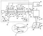
도 1은 재료(11)를 레이저 프로세싱하기 위한 장치(10)를 도시한 것으로, 그 장치는 레이저(1) 및 빔 전달 케이블(2)을 포함하고, 여기서:1 shows an


장치(10)는:


이에 의해 빔 파라미터 곱(4)이 스퀴징 힘(12)을 조정하는 것에 의해 변화되는 것이 가능한 것을 특징으로 한다.It is characterized in that it is thereby possible for the beam parameter product (4) to be varied by adjusting the squeezing force (12).
피치(7)는 주기적 표면(6)의 연이은 최대치들 사이의 거리이고, 주기적 표면(6)의 주기성 또는 공간 주파수의 역수이다. 주기적 표면(6)은, 도 1에 도시된 주기적 표면(6)과 같은, 단일 부분으로부터 이루어지는 연속적인 주기적 표면일 수 있다. 대안적으로, 주기적 표면(6)은 함께 조립되는 와이어들 또는 핑거들과 같은 복수의 부분들을 포함할 수 있다. 와이어들 또는 핑거들은 피치(7)가 조정 가능하도록 조정 가능할 수도 있다.The
도 1은 렌즈 시스템(24), 프로세싱 헤드(3) 및 포커싱 렌즈(25)에 광학적으로 커플링되는 장치(10)를 도시한다. 렌즈 시스템(24)은, 레이저 방사선(13)을 콜리메이팅 및/또는 확대하기 위한 하나 이상의 렌즈들을 포함할 수 있다. 프로세싱 헤드(3)는, 재료(11) 상에 레이저 방사선(13)을 스캐닝하기 위한 하나 이상의 스캐닝 시스템들을 포함할 수 있다. 포커싱 렌즈(25)는 포커스 포인트(29)에서의 재료(11) 상으로 레이저 방사선(13)을 포커싱할 수 있다.1 shows an
빔 파라미터 곱(4)은 포커싱된 레이저 방사선(13)의 빔 직경 2ω(21)의 절반과 발산 각도 α(22)의 곱과 동일하다. 빔 파라미터 곱(4)은, M2 값에 의해 또한 특성화될 수 있는 레이저 빔의 빔 품질의 척도이다. 빔 파라미터 곱(4)은 M2.λ/π와 동일하고, 여기서 λ는 레이저 방사선(13)의 파장(23)이다. 단일 모드 섬유 레이저는 전형적으로 대략 1.1의 M2을 갖는다. 파장(23)이 1.06 ㎛인 경우, 그러면 빔 파라미터 곱(4)은 0.35 ㎜.mrad와 동일하다. 레이저 빔의 빔 파라미터 곱(4)은, 어떠한 수차들도 갖고 있지 않은 렌즈들을 포함하는 단순한 광학 시스템들에서 보존된다. 따라서, 포커스(29)에서의 빔 파라미터 곱(4)은 레이저 방사선(13)의 빔 파라미터 곱(34)과 대략 동일한데, 이는 그것이 레이저 방사선(13)이 방출되게 하는 빔 전달 케이블(2)의 출력 단부(28)로부터 나타나기 때문이다. 포커스(29)에서의 빔 직경(21)은, 빔 전달 케이블(2)의 출력 단부(28)에서의 빔 직경(27)과, 렌즈 시스템(24) 및 포커싱 렌즈(24)를 포함하는 광학 시스템의 배율의 곱과 실질적으로 동일하다. 레이저 방사선(13)의 발산(22)은, 빔 전달 케이블(2)의 출력 단부(28)로부터 방출된 레이저 방사선(13)의 발산(35)과, 광학 시스템의 배율의 지수와 실질적으로 동일하다. 따라서, 빔 직경(21)이 빔 직경(27)보다 더 큰 경우, 그러면 발산(22)은 발산(35)보다 더 작다.The beam parameter product ( 4 ) is equal to the product of half the beam diameter 2ω ( 21 ) of the
레이저 방사선(13)은 광섬유(9), 광섬유(19)(존재한다면), 및 빔 전달 케이블(2)을 따라 유도된다. 레이저 방사선(13)은, 스퀴징 메커니즘(5)에 의해 조정 또는 스위칭될 수 있는 유도된 빔 직경(39) 및 유도된 빔 프로파일(38)을 갖는다. 따라서, 도 1에 도시된 바와 같이, 레이저(1)의 출력에서 대략 가우시안 빔 프로파일로서 도시되는 유도된 빔 프로파일(38)은, 톱 햇 빔 프로파일을 갖는 것으로서 도시되는 출력 빔 프로파일(14)이 되도록 조정되었다. 출력 빔 직경(27)은 유도된 빔 직경(39)보다 더 큰 것으로서 도시되어 있다.
광섬유(9) 및 스퀴징 메커니즘(5)을 선택하는 것에 의해, 그리고 스퀴징 힘(12)을 변화시키는 것에 의해, 범위 0.3 ㎜.mrad 내지 30 ㎜.mrad에서의 전형적인 산업용 레이저들의 빔 파라미터 곱(4)을 조정하는 것이 가능하다. 유리하게는, 스퀴징 힘(12)을 선택하는 것에 의해 빔 직경(27) 및 발산(35) 양측 모두가 제어될 수 있다. 또한, 레이저 방사선(13)의 출력 빔 프로파일(14)을, 예를 들어 도 1에 도시된 유도된 빔 프로파일(38)과 같은 종-형상 가우시안 빔 프로파일로부터, (도 1에 도시된 출력 빔 프로파일(14)과 같은) 톱 햇 빔 프로파일로 또는 링 프로파일로 조정 또는 스위칭하는 것이 가능하다. 출력 빔 프로파일(14)을 조정 또는 스위칭하는 능력은 많은 레이저 절삭 적용들에 매우 바람직하다. 출력 빔 프로파일(14)을 변경하는 것이 가능하다는 것은 많은 레이저 재료 프로세싱 적용들에 바람직하다. 예를 들어, 가우시안 프로파일은 재료(11)를 관통하는 데 유리할 수 있고, 톱 햇 프로파일 또는 링 프로파일은 재료(11)를 절삭하는 데 유리할 수 있다. 상이한 출력 빔 프로파일들(14)은 상이한 적용들에 유리하고, 최적의 출력 빔 프로파일은 재료(11) 및 그 두께(26)에 의존할 것이다.By choosing the
렌즈 시스템(24)은 콜리메이션 광학계, 가변 빔 확장기, 및/또는 망원경을 포함할 수 있다. 렌즈 시스템(24)은 재료(11) 상의 포커싱된 레이저 방사선(13)의 직경(21)을 변화시키도록 구성될 수 있다. 렌즈 시스템(24)과 관련하여 스퀴징 메커니즘(5)의 사용은 레이저 방사선(13)의 발산(22) 및 레이저 방사선(13)의 빔 직경(21)이 독립적으로 변화될 수 있게 한다. 이것은, 장치가 작은 직경(21)에 의한 높은 빔 품질(M2 < 4), 중간 빔 직경(21)에 의한 중간 빔 품질(10 내지 20의 M2), 큰 빔 직경(21)에 의한 낮은 빔 품질(30보다 더 큰 M2)을 제공하게 하는, 극도로 매력적인 특징이다. 부가적으로, 중간 또는 낮은 빔 품질을 갖는 작은 빔 직경(21), 및 낮은 또는 높은 빔 품질을 갖는 중간 빔 직경(21)을 생성하는 것이 가능하다. 이 유연성의 정도는 절삭과 같은 재료 프로세스들을 최적화시킴에 있어서 훨씬 더 큰 자유를 가능하게 한다. 초점 스폿 사이즈 및 발산은 각각의 판금 타입 및 두께마다 최적화될 수 있다. 장치는 스테인리스 강을 절삭하기 위한 높은 빔 품질(낮은 빔 파라미터 곱(4)), 및 두께(26)를 갖는 연강을 절삭하기 위한 낮은 빔 품질(보다 높은 빔 파라미터 곱(4))을 갖는 레이저 방사선(13)을 생성하도록 설정될 수 있다. 전자의 경우에, 재료(11) 상에 포커싱될 때 레이저 방사선(13)의 빔 직경(21)은 후자의 경우에서보다 더 작고 발산이 더 적어야 한다.The
본 발명은 레이저들로 금속들을 절삭하는 데 유리하다. 레이저(1)는 파이버 레이저, 디스크 레이저, 또는 솔리드 스테이트 레이저일 수 있다. 레이저(1)는 범위 500 W 내지 20 kW에서의 출력 전력에 의해 규정될 수 있다.The present invention is advantageous for cutting metals with lasers. The
실험에서, 레이저(1)는 3 kW 이터븀-도핑된 파이버 레이저이었다. 파장(23)은 1.07 ㎛이었다. 재료(11)는 스테인리스 강이었다. 포커싱된 빔 직경(21)은 200 ㎛이었고, 출력 빔 프로파일(14)은 톱 햇 프로파일이었다. 범위 2 ㎜ 내지 8 ㎜에서의 두께(26)를 갖는 스테인리스 강을 절삭할 때, 대략 4.8 ㎜.mrad의 빔 파라미터 곱(4)에 대한 것보다 대략 3.0 ㎜.mrad의 빔 파라미터 곱(4)으로 더 높은 절삭 속도들 및 더 양호한 절삭 품질이 획득되었다. 역으로, 재료(11)가 범위 15 ㎜ 내지 30 ㎜에서의 두께(26)를 갖는 연강일 때, 3.0 ㎜.mrad의 빔 파라미터 곱(4)보다 대략 4.8 ㎜.mrad의 빔 파라미터 곱(4)으로 더 양호한 결과들이 획득되었다. 출력 프로파일(14)은 톱 햇 프로파일이었다. 연강에 대한 더 낮은 빔 품질(더 높은 빔 파라미터 곱(4))은 절삭-에지 면의 품질을 개선시켜서, 표면 거칠기를 감소시켰다.In the experiments,
레이저 절삭 프로세스는 레이저 빔(13)으로 재료(11)를 관통하는 것으로 시작한다. 절삭할 때보다 관통할 때 포커스 스폿(29)에서 더 적은 발산(22)을 갖는 더 작은 빔 직경(21)을 사용하는 것이 유리하다. 출력 프로파일(14)은 바람직하게는 가우시안 프로파일과 같은 종 형상 프로파일이다. 이것은 관통의 품질 및 속도를 증가시킨다. 모든 금속들을 관통할 때 빔 파라미터 곱(4)은 3 ㎜.mrad 미만, 바람직하게는 1 ㎜.mrad 미만, 그리고 더 바람직하게는 0.5 ㎜.mrad 미만이어야 한다.The laser cutting process begins with a
빔 전달 케이블(2)의 출력 단부(28)에서 방출되는 빔 직경(27), 발산(35) 및 출력 빔 프로파일(14)을 선택하는 것이 가능하다는 이점은, 상이한 빔 직경들(21) 및 발산 각도들(22)이 포커스 포인트(29)에서 선택될 수 있게 하는데, 이 포커스 포인트(29)는 재료(11) 위에, 그 내에, 또는 그 아래에 있을 수도 있다. 예를 들어, 스테인리스 강의 경우, 포커스 포인트(29)는 레이저 방사선(13)이 재료(11)에서 수렴하고 있도록 재료(11) 아래에 있을 수 있는 반면, 연강의 경우, 포커스 포인트(29)는 레이저 방사선이 재료(11)에서 발산하고 있도록 재료(11) 위에 있을 수 있다. 메커니즘들(5) 중 하나 이상을 조정하는 것에 의해 그와 같이 되는 것이 가능하다는 것은 종래 기술보다 주요한 이점인데, 이는 그것이, 포커싱 광학계의 배율을 조정하는 것을 포함하는 대안보다 더 낮은 비용 및 더 단순한 시스템을 제공하기 때문이다.The advantage that it is possible to select the
관통한 후에, 보조 가스가 용융된 금속 및 잔해를 관통-홀 출구 밖으로 분출시킨다. 이 스테이지에서, 빔 직경(28) 및 발산(35)은 포커스 스폿(29)에서 최적의 빔 직경(21) 및 발산 각도(22)를 제공하도록 증가될 수 있다. 결과적인 빔 파라미터 곱(4)은 프로세싱되는 재료(11)에 따라 선택될 수 있다.After penetrating, an auxiliary gas ejects the molten metal and debris out of the through-hole exit. At this stage, the
스퀴징 메커니즘(5)은 바람직하게는 대향하는 주기적 표면(42)을 갖는다. 주기적 표면(6) 및 대향하는 주기적 표면(42)은 바람직하게는 도 1에 도시된 바와 같이 서로에 대해 동위상이다. 따라서, 주기적 표면(6) 및 대향하는 주기적 표면(42)이 광섬유(9)에 대해 스퀴징됨에 따라, 광섬유(9)는 스프링으로서 작용하고 그 길이를 따라 주기적으로 편향되어 광섬유(9)의 변형 에너지가 최소화되도록 한다. 광섬유(9)의 편향은 주기적 표면(6)과 동일한 피치(7)를 가질 것이지만, 주기적 표면(6)의 주기성보다 더 높은 공간 주파수들에서 부가적인 고조파들을 포함할 수도 있다. 스퀴징 힘(12)이 증가함에 따라, 광섬유(9)가 주기적 표면(6)과 대향하는 주기적 표면(42) 사이에서 그리핑될 때까지 광섬유(9)의 편향이 그와 같이 된다. 스퀴징 힘(12)의 추가 증가들은 광섬유(9)를 가로지르는 스퀴징 응력들을 유발할 것이다.The squeezing
주기적 표면(6) 및 대향하는 주기적 표면(42)은 서로에 대해 논-제로 위상(non-zero phase)을 가질 수도 있다. 그러한 설계는 광섬유(9)에 의해 지지되는 부가적인 세트들의 광학 모드들 사이의 커플링을 유발할 수도 있는 광섬유(9)의 비틀림으로의 부가적인 고조파들을 유발할 수 있다.
주기적 표면(6)과 대향하는 주기적 표면(42) 사이의 위상은 광섬유(9)가 주기적 표면(6)과 대향하는 주기적 표면(42) 사이에서 그리핑되도록 반대 위상으로 있을 수 있다. 그 후에, 광탄성 효과에 의해 유발된 주기적 섭동들에 의해 모드 커플링이 야기된다.The phase between the
도 1의 장치는 피치(17)에 의해 규정되는 주기적 표면(16)을 포함하는 제2 스퀴징 메커니즘(15)을 갖는 것으로서 도시되어 있다. 주기적 표면(16)은 광섬유(19)의 길이(18)에 대해 스퀴징될 수 있다. 제2 스퀴징 메커니즘(15)의 사용은, 요구되는 빔 직경(27), 발산(35) 및 출력 빔 프로파일(14)을 획득하는 데 요구되는 스퀴징 힘(12)을 감소시켜서, 그에 의해 광섬유(9)를 파단할 위험을 감소시키고 기계적 신뢰성을 증가시킬 수 있다. 제2 스퀴징 메커니즘(15)은 또한, 고차 광학 모드들을 함께 커플링시키는 데 사용될 수 있는데, 그 경우에 피치(17)는 바람직하게는 피치(7)보다 더 길다.The apparatus of FIG. 1 is shown as having a second squeezing
도 1에 도시된 바와 같이, 주기적 표면(16)은 처핑될 수도 있고, 즉 그 피치(17)는 스퀴징 메커니즘(15)의 길이를 따라 변화될 수도 있다. 피치(17)는 (도시된 바와 같은) 단조 방식 또는 비-단조 방식으로 변화될 수 있다. 처프는 요망되는 빔 파라미터 곱(4) 또는 출력 빔 프로파일(14)을 획득하는 데 요구되는 스퀴징 힘(12)의 양을 감소시켜서, 그에 의해 신뢰성을 증가시킨다. 도 2는 처핑되는 스퀴징 메커니즘(15)의 예를 도시한다. 스퀴징 메커니즘(15)은 대향하는 주기적 표면(41)을 가지며, 광섬유(19)(도시되지 않음)는 주기적 표면(16)과 대향하는 주기적 표면(41) 사이에서 스퀴징된다. 스퀴징 힘(12)은 태핑된 홀들일 수도 있는 홀들(43) 중 적어도 하나를 통해 인가될 수 있다. 대향하는 주기적 표면(41)은 홀들(44) 중 적어도 하나를 통해 피팅되는 고정 나사들을 사용하여 제위치에 고정될 수 있다.1 , the
주기적 표면(16) 및 대향하는 주기적 표면(41)은 바람직하게는 도 1에 도시된 바와 같이 서로에 대해 동위상이다. 따라서, 주기적 표면(16) 및 대향하는 주기적 표면(41)이, 도 1을 참조하여 도시된 광섬유(19)에 대해 스퀴징됨에 따라, 광섬유(19)는 스프링으로서 작용하고 그 길이를 따라 편향되어 광섬유(19)의 변형 에너지가 최소화되도록 한다. 편향은 주기적 표면(16)과 동일한 피치(17)를 가질 것이지만, 광섬유(19)에 의해 유도되는 부가적인 모드들을 함께 커플링시키는 것이 바람직할 수도 있는 부가적인 고조파들을 포함할 수도 있다. 스퀴징 힘(12)이 증가함에 따라, 광섬유(19)가 주기적 표면(16)과 대향하는 주기적 표면(41) 사이에서 그리핑될 때까지 광섬유(19)의 편향이 그와 같이 된다. 스퀴징 힘(12)의 추가 증가들은 광섬유(19)를 가로지르는 스퀴징 응력들을 추가로 유발할 것이다. 대안적으로, 주기적 표면(16) 및 대향하는 주기적 표면(41)은 서로에 대해 논-제로 위상을 가질 수도 있다. 그러한 설계는 광섬유(19)에 의해 지지되는 부가적인 세트들의 광학 모드들 사이의 커플링을 유발할 수도 있는 광섬유(19)의 비틀림으로의 부가적인 고조파들을 유발할 수 있다. 주기적 표면(16)과 대향하는 주기적 표면(41) 사이의 위상은 광섬유(19)가 주기적 표면(16)과 대향하는 주기적 표면(41) 사이에서 그리핑되도록 반대 위상으로 있을 수 있다. 그 후에, 광탄성 효과에 의해 유발된 주기적 섭동들에 의해 모드 커플링이 야기된다.
스퀴징 메커니즘(5)은, 도 3에 도시된 스퀴징 메커니즘(40)에 도시된 바와 같이 서로에 대해 각도(45)를 이루도록 배열되는 주기적 표면들(6) 중 2개를 포함할 수도 있다. 주기적 표면들(6) 각각은 동일한 또는 유사한 설계의 대향하는 주기적 표면(42)을 갖는다. 도 1 및 도 2를 참조하여 설명된 바와 같이, 주기적 표면들(6)은 이들의 각각의 대향하는 주기적 표면(42)과 동일한 위상을 가질 수도 있다. 주기적 표면(6) 각각이 광섬유(9)에 대해 스퀴징됨에 따라, 광섬유(9)의 길이는 스프링으로서 작용하고 그 길이를 따라 비틀린다. 스퀴징 메커니즘(40)의 주기적 표면들(6)은 서로 동일한 피치(7) 또는 서로 상이한 피치(7)를 가질 수도 있다. 각도(45)는 직각일 수도 있다. 스퀴징 메커니즘(40)은 단면에 도시되어 있는데, 이때 광섬유(9)가 주기적 표면들(6) 중 하나에 의해 스퀴징 메커니즘(40)의 중심 라인으로부터 오프셋된 것으로 도시되어 있다.The squeezing
스퀴징 메커니즘(40)은 각각의 주기적 표면(6)이 상이한 스퀴징 힘들(12)로 광섬유(9)에 대해 스퀴징되는 것이 가능하도록 할 수도 있다. 2개의 주기적 표면들(6)의 공간 위상들은 서로에 대해 90도의 위상차가 있을 수도 있어서, 스퀴징 힘들(12)이 2개의 주기적 표면들(6)에 인가될 때 광섬유(9)가 실질적으로 나선형 방식으로 변형될 수 있다. 도 1 및 도 2를 참조하여 설명된 바와 같이, 광섬유(9)는 스프링으로서 작용하고, 그 변형 에너지를 최소화시키도록 변형될 것이다. 그에 따라, 광섬유(9)의 변형은 정확히 나선형이 아닐 수도 있지만, 고조파들을 포함할 수도 있다. 이들 고조파들은 광섬유(9)에 의해 유도되는 특정 세트들의 광학 모드들 사이의 커플링에 유리할 수 있다. 이 배열은 광섬유(9)의 어떤 유도된 모드들이 어떤 것에 커플링되는지에 대한 큰 제어를 제공한다.The squeezing
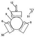
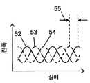
스퀴징 메커니즘(5)은, 도 4에 도시된 스퀴징 메커니즘(50)에 도시된 바와 같이 서로에 대해 각도(51)를 이루도록 배열되는 홀수 개의 주기적 표면들(6)을 포함할 수도 있다. 각도(51)는 바람직하게는 180도와 (n-2)/n의 곱이고, 여기서 n은 주기적 표면들(6)의 수이다. 도 5를 참조하여 도시된 바와 같이, 주기적 표면들(6)은 바람직하게는 360도가 주기적 표면들(6)의 수로 나누어진 것과 동일한 서로에 대한 상대 공간 위상들(55)을 갖는다. 홀수 개는 바람직하게는 3개이고, 각도(51)는 바람직하게는 60도이다. 도 5는 스퀴징 메커니즘(50)의 길이를 따라 도 4에 도시된 3개의 주기적 표면들(6) 각각의 진폭들(52, 53, 54)을 도시한다. 주기적 표면들(6)은 서로에 대해 120도의 상대 공간 위상(55)을 갖는다. 주기적 표면(6) 각각이 광섬유(9)에 대해 스퀴징됨에 따라, 광섬유(9)의 길이는 스프링으로서 작용하고 실질적으로 나선형 방식으로 그 길이를 따라 비틀어진다. 도 1, 도 2, 및 도 3을 참조하여 설명된 바와 같이, 광섬유(9)는 스프링으로서 작용하고, 그 변형 에너지를 최소화시키도록 변형될 것이다. 그에 따라, 광섬유(9)의 변형은 그 길이를 따라 정확하게 나선형이 아닐 수도 있지만, (피치(7)의 역수로서 규정되는) 나선형의 주기성의 고조파들을 포함할 수도 있다. 이들 고조파들은 광섬유(9)에 의해 유도되는 특정 세트들의 광학 모드들 사이의 커플링에 유리할 수 있다.The squeezing
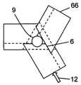
스퀴징 메커니즘(5)은, 부분들(66) 중 다른 것의 주기적 표면(6)에 정렬되도록 설계되는 제2 주기적 표면(61)을 갖는 적어도 3개의 부분들(66)을 포함하는, 도 6을 참조하여 도시된 스퀴징 메커니즘(60)일 수도 있다. 도 4 및 도 5를 참조하여 설명된 바와 같이, 3개의 주기적 표면들(6)은 바람직하게는 서로에 대해 120도의 상대 공간 위상(55)을 갖는다. 부분들(66)이 서로 피팅되도록 하기 위해, 부분들(66) 각각의 제2 주기적 표면(61)은 동일한 부분(66)의 주기적 표면(6)에 대해 120도의 상대 공간 위상(55)을 갖는다. 도 7은 3개의 부분들(66)이 함께 피팅되고 스퀴징 힘(12)이 인가된 하나의 배열을 도시한다. 광섬유(9)는 부분들(66) 중 하나에 의해 편향되어 도시된다. 제2 주기적 표면들(61) 중 하나가 광섬유(9)에 대해 스퀴징되는 배열들을 포함하여, 부분들(66)을 함께 피팅하기 위한 다른 배열들도 또한 가능하다. 실험적으로, 광섬유(9)에 의해 유도되는 LP01 모드는 LP31 및 LP32 모드들에 우선적으로 커플링될 수 있다는 것이 관측되었다. 이것은 스퀴징 메커니즘(50)의 3배의 대칭성의 결과로서 될 수도 있다. 유리하게는, 도 3 내지 도 7을 참조하여 설명된 스퀴징 메커니즘들(40, 50, 60)의 스퀴징 힘은, 광섬유(9)에 의해 유도되는 기본 LP01로부터의 유사한 레벨의 모드 커플링을 위해 도 2를 참조하여 도시된 스퀴징 메커니즘(15)보다 실질적으로 더 적은 스퀴징 힘들(12)을 요구한다. 실험에서, 스퀴징 힘(12)은, 상당한 양들의 모드 커플링이 있음에도 불구하고, 1 N보다 더 적은 힘으로 도 7에 도시된 스퀴징 메커니즘으로부터 광섬유(9)가 당겨질 수 있도록 상당히 작았다. 동일한 레벨들의 모드 커플링에 대해 스퀴징 힘(12)을 감소시키는 능력은 신뢰성을 개선시킨다.6 , the squeezing
장치는, 복수의 스퀴징 메커니즘들(5)을 포함할 수도 있다. 복수의 스퀴징 메커니즘들을 포함시키면, 스퀴징 메커니즘들(5) 각각에 요구되는 스퀴징 힘들(12)을 감소시켜서, 그에 의해 신뢰성을 개선시킬 수 있다.The apparatus may comprise a plurality of squeezing
스퀴징 메커니즘들(5) 중 적어도 하나는 스퀴징 메커니즘들(5) 중 다른 것과는 상이한 피치(7)를 가질 수도 있다. 상이한 피치들(7)은 광섬유(9)에서의 유도된 모드들의 상이한 그룹들 사이의 커플링을 야기한다. 상이한 피치들(7)을 갖는 스퀴징 메커니즘들(5)을 조합하면, 출력 빔 파라미터 곱(4) 및 출력 빔 프로파일(14)의 보다 큰 제어를 제공한다.At least one of the squeezing
스퀴징 메커니즘(5)은 도 1 내지 도 4, 도 6 및 도 7을 참조하여 도시된 바와 같은 선형 스퀴징 메커니즘(5)일 수도 있다. 이것은 공간이 장려되는 경우 유리하다.The squeezing
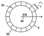
스퀴징 메커니즘(5)은 도 8에 도시된 바와 같은 실린더(81)를 포함할 수도 있다. 광섬유(9)(도시되지 않음)는 실린더(81) 둘레에 감겨 있을 수도 있다. 스퀴징 힘(12)은 예를 들어 링(82)으로 광섬유(9)를 스퀴징하는 것에 의해 실린더(81)의 축을 따라 인가될 수도 있다. 링(82)은 대향하는 주기적 표면(42)을 갖는 것으로 도시되어 있지만, 그것이 반드시 그러할 필요는 없다. 피치(7)는, 각각의 주기가 라인(83)에 의해 도시되는 도 9 및 도 10의 주기적 표면(6)의 예들의 상부 표면들 각각에 의해 도시된 바와 같이, 균일하거나 또는 처핑될 수도 있다. 주기적 표면(6)은 도 8에 도시된 바와 같은 평면에 또는 만곡된 표면 상에 구성될 수도 있다. 실린더(81)는 원형 또는 타원형일 수도 있다. 다른 형상들도 또한 가능하다. 피치(7)는 실린더(81)의 주연부(85)의 반경(84)을 따라 변화될 수도 있다. 이것은 처핑된 장기 주기 격자들이 제조될 수 있게 한다.The squeezing
실린더(81)의 형태의 스퀴징 메커니즘(5)은 선형 스퀴징 메커니즘(5)에 의한 것보다 더 긴 길이(8)의 광섬유(9) 위에 스퀴징 힘(12)을 인가하는 것이 더 편리해지는 콤팩트한 배열을 제공하고, 광섬유(9)의 1 회전 초과가 사용되는 것을 가능하게 한다. 이것은 보다 작은 스퀴징 힘들(12)이 인가될 수 있게 하여, 그에 의해 장기 신뢰성을 개선시킨다. 그것은 또한 스퀴징될 때 광섬유(9)의 광학 손실들을 감소시키는 데 도움이 된다.A squeezing
광섬유(9) 및/또는 광섬유(19)는 도 11을 참조하여 도시된 광섬유(90)일 수 있다. 광섬유(90)는 코어(91), 유리 클래딩(94), 및 폴리머 코팅(95)을 갖는다. 코어(91)는 바람직하게는 적어도 10 ㎛의 직경(92)을 갖는다. 직경(92)은 적어도 15 ㎛일 수도 있다. 직경(92)은 적어도 50 ㎛일 수도 있다. 코어 직경(92)을 증가시키면, 광섬유(90)가 증가하는 수의 광학 모드들을 유도할 수 있게 한다.The
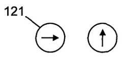
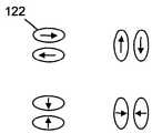
코어(91)는 유리 클래딩(94)의 굴절률(99)보다 더 큰 굴절률(96)을 갖는다. 바람직하게는 광섬유(9)는, 도 12를 참조하여 도시된 적어도 기본 모드(121) 및 도 13을 참조하여 도시된 2차 모드(122)를 지원한다. 기본 모드(121)는 2개의 직교 편광 상태들에서 발생할 수 있는 LP01 모드일 수도 있다. 2차 모드(122)는 2개의 배향들로 발생할 수 있는 LP11 모드일 수도 있는데, 이들 양측 모두는 2개의 직교 편광 상태들에서 발생할 수 있다. 따라서 도 12 및 도 13에 각각 도시된 바와 같이 2개의 기본 모드들(121) 및 4개의 2차 모드들(122)이 있다.The
LP01 및 LP11 모드들은 더 일반적으로는 LPp,q 모드들로서 설명되고, 여기서 p는 방위각 모드 번호이고, q는 방사 모드 번호이다. 2p는 방위각 둘레의 로브들의 수이고, q는 반경을 따르는 로브들의 수이다. 따라서 LP01 모드는 방위각 둘레의 제로 로브들, 및 반경을 따르는 하나의 로브를 갖는다. LP11 모드는 방위각 둘레의 2개의 로브들, 및 반경을 따르는 하나의 로브를 갖는다. 스퀴징 메커니즘(5)에 의해 유발된 광섬유(9)의 섭동, 제1 모드의 전기장, 및 제2 모드의 전기장의 곱의 중첩 적분들이 광섬유(9)의 길이(8)에 걸쳐 논-제로 값으로 적분되는 경우, 스퀴징 메커니즘(5)은 제1 모드를 제2 모드에 커플링할 것이다. 아래에 설명되는 바와 같이, 이것은, 제1 모드 및 제2 모드의 전파 상수들, 및 주기적 표면(7)의 주기성에 대해 요건들을 둔다. 그것은 또한, 광섬유의 섭동과 비교하여 제1 모드 및 제2 모드의 전기장들에 대해 대칭성 요건들을 둔다.The LP01 and LP11 modes are more generally described as LPp,q modes, where p is the azimuth mode number and q is the radiation mode number. 2p is the number of lobes around the azimuth and q is the number of lobes along the radius. The LP01 mode thus has zero lobes around the azimuth, and one lobe along the radius. The LP11 mode has two lobes around the azimuth and one lobe along the radius. The superimposed integrals of the product of the perturbation of the
도 11을 참조하면, 기본 모드(121)는 β1/k의 유효 인덱스(97)를 가지며, 2차 모드(122)는 β2/k의 유효 인덱스(98)를 가지며, 여기서 β1 및 β2는 기본 모드(121) 및 2차 모드(122) 각각의 전파 상수들이고, k는 k = 2π/λ에 의해 레이저 방사선(13)의 파장 λ(23)에 관련된 파수이다. 전파 상수들의 차이 Δβ = β1-β2를 고려하는 것이 유용하다. 도 1 내지 도 7을 참조하여 도시된 스퀴징 메커니즘(5)이 LP01 모드를 LP11 모드에 커플링시키기 위해, Δβ/2π와 동일한 길이를 따르는 광섬유(9)의 비틀림에 있어서의 공간 주파수 성분이 있다는 것이 요구된다. 이것은, (피치(7)의 역수로서 규정되는) 주기성이 Δβ/2π와 동일하거나, 또는 주기성의 고조파가 Δβ/2π와 동일한 경우, 발생할 것이다. 그러나, 광학 모드들과 비교하여 광섬유(9)의 섭동의 대칭성을 고려하는 것도 또한 중요하다.Referring to FIG. 11 , the
p가 논-제로인 경우, 그러면 광섬유(9)의 코어에 의해 유도되는 각각의 LPp,q 모드에 대한 전기장들의 방위각 의존성은 다음의 것에 의해 표현될 수 있다:If p is non-zero, then the azimuthal dependence of the electric fields for each LPp,q mode induced by the core of the


여기서 E(r)은 전기장의 방사 의존성이고, cos(pθ) 및 sin(pθ)는 (p = 1의 경우) 도 13에 도시된 2개의 배향들을 나타낸다.where E(r) is the radiation dependence of the electric field, and cos(pθ) and sin(pθ) represent the two orientations shown in FIG. 13 (for p = 1).
광섬유(9) 또는 광섬유(19)가 (예를 들어 피치(7)가 길이(8)를 따라 균일한 도 1 및 도 2에 도시된 바와 같은 선형 스퀴징 메커니즘에 의해 유발된) 길이를 따르는 선형 사인파 편향을 가질 때, 그러면 대칭성 고려사항들에 의해, 피치(7)가 2/Δβ와 동일할 때 이들 2개의 배향들 중 하나만이 커플링될 것이다. 이것은 도 13의 2차 모드들(122)이 퇴보한 것으로 가정한다. 더 일반적으로는, 코어에 의해 유도되는 LP01 모드는 피치(7)가 2π/(βA-βB)와 동일한 경우 p가 홀수 정수인 경우 동일한 코어에 의해 유도되는 LPp,q 모드에 커플링할 수 있고, 여기서 βA 및 βB는 함께 커플링되는 광학 모드들의 전파 상수들이다. 그러나, 사인파 편향에 상당한 고조파들이 없는 한, LP11 모드에의 커플링이 가장 강력할 것이다. p가 짝수 정수인 경우, 그러면 섭동의 대칭성이 올바르지 않다. 유사한 대칭성 인수에 의해, 선형 스퀴징 메커니즘은 또한, 섬유가 그 길이를 따라 사인파 편향을 갖는 경우 LP01 모드를 LP0q 모드에 커플링하지 않을 것이다. 아래에 설명되는 바와 같이, 중심 코어에 의해 유도되는 LP01 모드 및 다른 광학 모드들은 또한, 중심 코어에 인접한 위성 코어들에 의해 유도되는 광학 모드들에 커플링할 수 있다. 그러한 커플링은 상기에 언급된 중첩 적분이 제로가 아닌 경우 발생할 수 있다.The
주기적 표면(6) 및 대향하는 주기적 표면(42)이 (도 1에 도시된 동위상 배열과는 대조적으로) 반대 위상으로 있는 경우, 그러면 광섬유(9)는 그 길이를 따라 주기적으로 압축될 것이다. 그 후에, 모드 커플링이 광탄성 효과에 의해 유발될 것이다. 대칭성 고려사항들에 의해, 대칭성이 올바르지 않기 때문에 LP01 모드가 LP11 모드와 커플링하지 않을 것이다. 그러나, LP01 모드는 피치(7)가 2π/(βA-βB)와 동일한 경우 LP21 모드, 또는 더 일반적으로는 LPp,q 모드들 - 여기서 p = 2, 4, 8 등이다 - 에 커플링하는 것이 가능하고, 여기서 βA및 βB는 함께 커플링되는 광학 모드들의 전파 상수들이다. 그러나, 이 배열은 일반적으로 선호되지 않는데, 이는, 주목할 만한 모드 커플링을 획득하기 위해 요구되는 스퀴징 힘(12)이, 주기적 표면(6) 및 대향하는 주기적 표면(42)이 도 1에 관련하여 도시된 바와 같이 동위상일 때 요구되는 스퀴징 힘(12)보다 일반적으로 훨씬 더 크기 때문이다.If the
광섬유(9) 또는 광섬유(19)가 (예를 들어, 도 3, 도 4, 도 6 및 도 7에 도시된 스퀴징 메커니즘들 중 하나에 의해 유발된) 나선형 비틀림을 가질 때, 그러면 대칭성 인수들에 의해, 피치(7)가 2π/Δβ와 동일할 때 양측 모두의 배향들에서 LP01 모드가 LPp,q 모드들에 커플링할 수 있다. 그러나, 그것은, p가 짝수 정수인 경우에, 또는 LP0q 모드에, 커플링하지 않을 것이다. 따라서, 도 1 및 도 2에 도시된 스퀴징 메커니즘들보다 도 3, 도 4, 도 6 및 도 7에 도시된 스퀴징 메커니즘들에 의해 제공되는 모드 커플링의 양의 적어도 2배가 있다. 도 5를 참조하여 논의된 바와 같이, 스퀴징 메커니즘(60)은, 광섬유(90)를 나선형으로 변형시키는 3개의 부분들(60)을 포함한다. LP01 모드는 LP31 및 LP32 모드들에 커플링된 것으로 관측되었다. 이것은, 커플링을 위해 요구되는 대칭성을 제공하는 스퀴징 메커니즘(60)에 의해 유발되는 광섬유(90)를 따르는 3배 방위각 섭동이 있다는 것을 암시한다.When
이전과 같이, 메커니즘들(40, 50 및 60)의 주기적 표면(6) 및 대향하는 주기적 표면(42)이 반대 위상으로 있어서 광섬유(9)가 그 길이를 따라 주기적으로 압축되는 경우, 그러면 모드 커플링은 상이한 세트의 광학 모드들 사이에 있다. 대칭성 고려사항들로부터, LP01 모드는 LP0q 모드들에 커플링할 것이다. 이 배열은 일반적으로 선호되지 않는데, 이는 그것이 비교할 만한 효과를 위해 보다 큰 스퀴징 힘들(12)을 요구하기 때문이다.As before, if the
일단 LP01 모드로부터 커플링된다면, 광은 다른 고차 모드들로 더 쉽게 커플링 또는 분산될 수 있는데, 이는 (ⅰ) 이들 모드들 사이의 전파 상수들의 차이 Δβ가 LP01 모드와 그것이 커플링한 제1 모드 사이의 전파 상수들의 차이 Δβ보다 일반적으로 더 작고, (ⅱ) 통계적으로, 주기성보다 더 긴 공간 주파수들로 발생하는 섭동들이 광섬유(9)에 있을 것이기 때문이다.Once coupled from the LP01 mode, light can be more easily coupled or dispersed into other higher-order modes, where (i) the difference Δβ in the propagation constants between these modes is equal to the LP01 mode and the first Because the difference in propagation constants between
나선형 방식으로 섭동되는 광섬유(9)를 갖는 도 3, 도 4, 도 6 및 도 7을 참조하여 도시된 나선형 스퀴징 메커니즘들(30, 40, 50, 60)은 그에 따라, 이들이 도 1 및 도 2를 참조하여 도시된 선형 스퀴징 메커니즘보다 더 많이 모드들의 배향들을 함께 커플링하고, 추가로, 커플링을 제공하기 위해 요구되는 스퀴징 힘(12), 그리고 그에 따라 광섬유(9)의 최대 편향이 더 적어져서 광섬유(9)에 인가되는 더 적은 응력, 그리고 따라서 더 높은 신뢰성을 발생시킨다는 점에서 유리하다. 실험적으로, 광섬유(9)는 1 N보다 더 적은 당기는 힘으로 도 7에 도시된 바와 같은 나선형 스퀴징 메커니즘들로부터 당겨질 수 있다는 것이 관측되었다. 이것은 도 2에 도시된 바와 같은 선형 스퀴징 메커니즘으로부터 광섬유(9)를 당기는 데 요구되는 당기는 힘보다 실질적으로 더 적고, 여기서 나선형 및 선형 스퀴징 메커니즘들은 광섬유(9)에서 유사한 레벨들의 모드 커플링을 유발한다. 그에 따라, 더 적은 스퀴징 힘들(12)이 나선형 스퀴징 메커니즘에서 광섬유에 인가되고 있어서, 더 큰 기계적 신뢰성을 암시한다.The helical squeezing
도 14에 도시된 바와 같이, 광섬유(9) 및 광섬유(19)는, 코어(91)에 인접한 적어도 하나의 위성 코어(141)를 가질 수 있다. 광섬유(140)는, 코어(91) 주위에 대칭적으로 이격되는 위성 코어들(141) 중 4개를 갖는다. 각각의 위성 코어(141)는 굴절률(142) 및 직경(143)을 가질 수 있어서, 도 15를 참조하여 도시된 그것의 광학 모드(151)는, 도 11 및 도 13을 참조하여 도시된 2차 모드(122)의 유효 인덱스 β2/k(98)와 실질적으로 동일한 유효 인덱스(143)를 갖는다. 그 후에, 광학 모드(151)는 2차 모드(122)에 공진 커플링할 것이다. 공진 커플링은 도 15에서 양단 화살표들로 표시된다. 따라서, 도 1, 도 2, 도 3, 도 4, 도 6 및 도 7을 참조하여 도시된 스퀴징 메커니즘(5)은 코어(91)의 LP01 모드를 코어(91)의 LP11 모드에 커플링하도록 구성될 수 있는데, 이 코어(91)의 LP11 모드는 그 후에 위성 코어들(141)의 광학 모드(151)에 커플링할 것이다. 대안적으로 또는 부가적으로, 도 1, 도 2, 도 3, 도 4, 도 6 및 도 7을 참조하여 도시된 스퀴징 메커니즘(5)이 광섬유(140)에 적용되는 경우, 그러면, 코어(91)가 2차 LP11 모드(122)를 지원하지 않도록 코어(91)의 설계가 된 경우에도, 스퀴징 힘(12)은 예컨대 LP01 기본 모드(121)로부터 위성 코어들(141)의 광학 모드(151)로 직접 커플링하는 것을 야기하도록 선택될 수 있다. 이전의 논의와 같이, 광섬유(9)가 선형 방식으로 사인파로 비틀어지는 경우, 그러면 커플링은 단지 하나의 방위각 배향에서 가장 강력할 것이다. 나선형 방식으로 비틀어진 경우, 그러면 모든 방위각 배향들에서 커플링이 발생할 것이다. 유리하게는, 위성 코어들(141)의 포함은 레이저 방사선(13)이 코어(91)로부터 위성 코어들(141)로 커플링될 수 있게 하여, 따라서 레이저 방사선(13)이 광섬유(9)를 따라 전파함에 따라 레이저 방사선(13)의 유도된 빔 직경(39)을 증가시킨다.14 , the
도 16에 도시된 바와 같이, 광섬유(9) 및 광섬유(19)는, 코어(91)를 둘러싸는 링 코어(161)를 갖는 광섬유(160)일 수 있다. 링 코어(161)는 굴절률(162) 및 두께(164)를 가질 수 있어서, 도 17을 참조하여 도시된 그것의 2차 모드(171)는, 도 11 및 도 13을 참조하여 도시된 2차 모드(122)의 유효 인덱스 β2/k(98)와 실질적으로 동일한 유효 인덱스(163)를 갖는다. 코어(91)의 2차 모드(122)가 광섬유(160)로 론칭되는 경우, 그러면 2차 모드(122)는 2차 모드(171)에 공진 커플링할 것이다. 대안적으로 또는 부가적으로, 도 1, 도 2, 도 3, 도 4, 도 6 및 도 7을 참조하여 도시된 스퀴징 메커니즘(5)이 광섬유(160)에 적용되는 경우, 그러면, 코어(91)가 2차 LP11 모드(122)를 지원하지 않도록 코어(91)의 설계가 된 경우에도, 스퀴징 힘(12)은 예컨대 LP01 기본 모드(121)로부터 링 코어(161)의 광학 모드(171)로 직접 커플링하는 것을 야기하도록 선택될 수 있다. 이전의 논의와 같이, 광섬유(9)가 선형 방식으로 사인파로 비틀어지는 경우, 그러면 커플링은 단지 하나의 방위각 배향에서 가장 강력할 것이다. 나선형 방식으로 비틀어진 경우, 그러면 모든 방위각 배향들에서 커플링이 발생할 것이다. 유리하게는, 링 코어(161)의 포함은 레이저 방사선(13)이 직접적으로 또는 간접적으로 2차 LP11 모드(122)를 통해 코어(91)로부터 링 코어(161)로 커플링될 수 있게 하여, 따라서 레이저 방사선(13)이 광섬유(9)를 따라 전파함에 따라 레이저 방사선(13)의 유도된 빔 직경(39)을 증가시킨다.As shown in FIG. 16 , the
도 11, 도 14 및 도 16을 참조하면, 유리 클래딩(94)은, 70 ㎛ 내지 500 ㎛인 직경(93)을 가질 수 있다. 직경(93)은 70 ㎛ 내지 200 ㎛일 수도 있다. 직경(93)은 바람직하게는 125 ㎛ 이하이다. 직경(93)은 더 바람직하게는 80 ㎛ 이하이다. 직경(93)을 감소시키면 광섬유(9)가 더 쉽게 변형될 수 있게 한다. 그것은 또한, 0.5 ㎜ 이하의 피치들(7)이 획득될 수 있게 하여, 따라서 전파 상수들의 더 큰 차이들을 갖는 모드들 사이의 커플링을 가능하게 한다. 그에 따라, 보다 작은 피치들(7)과 조합된 보다 작은 유리 직경들(93)은 종래 기술보다 유용한 이점들을 제공한다.11 , 14 and 16 , the
도 1 내지 도 4, 및 도 6 내지 도 10을 참조하면, 피치(7)는 12 ㎜보다 더 작을 수 있다. 피치(7)는 5 ㎜보다 더 작을 수 있다. 피치(7)는 범위 0.5 ㎜ 내지 5 ㎜에 있을 수 있다.1 to 4 and 6 to 10 , the
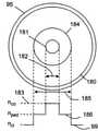
도 1을 참조하면, 광섬유(9), 또는 존재한다면 광섬유(19)는 빔 전달 케이블(2)에 커플링된다. 빔 전달 케이블(2)은, 도 18을 참조하여 도시된 광섬유(180)를 포함할 수도 있다. 광섬유(180)는 직경(182) 및 굴절률(183)을 갖는 코어(181)를 갖는다. 광섬유(180)는 또한, 직경(185) 및 굴절률(186)을 갖는 페데스탈(184)을 포함한다. 직경들(182 및 185) 및 굴절률들(183 및 186)은 광섬유(9) 또는 존재한다면 광섬유(19)의 코어(91)에서 전파하는 레이저 방사선(13)의 비례를 보존하도록 선택될 수 있다. 따라서, 예를 들어, 도 14의 광섬유(140)에 스플라이스(splice)된 경우, 직경(182)은 직경(92)과 실질적으로 동일하게 선택될 수 있고, 직경(185)은 외측 에지 대 외측 에지 거리(149)와 실질적으로 동일하거나 또는 그보다 더 크게 선택될 수 있다. 굴절률(186)은 굴절률(142)과 실질적으로 동일하거나 또는 그보다 더 높게 선택될 수 있다. 굴절률(183)은 굴절률(142)에 굴절률들(96 및 99)의 차이를 더한 것과 실질적으로 동일하게 선택될 수 있다. 따라서, 광섬유(140)의 코어(91)로부터 하나 이상의 위성 코어들(141)로 커플링되는 레이저 방사선(13)은 광섬유(180)의 페데스탈(184)에 커플링되고 빔 전달 케이블(2)을 따라 전파될 수 있다.Referring to FIG. 1 , an
빔 전달 케이블(2)은, 도 19를 참조하여 도시된 광섬유(190)를 포함할 수도 있다. 광섬유(190)는, 직경(192) 및 굴절률(193)을 갖는 코어(191)를 갖는다. 광섬유(190)는 또한, 직경(195), 굴절률(196), 및 두께(199)를 갖는 링 코어(194)를 포함한다. 직경들(192 및 195), 두께(199), 및 굴절률들(193 및 196)은 광섬유(9) 또는 존재한다면 광섬유(19)의 코어(91)에서 전파하는 레이저 방사선(13)의 비례를 보존하도록 선택된다. 따라서, 예를 들어, 도 16의 광섬유(160)에 스플라이스된 경우, 직경(192)은 직경(92)과 실질적으로 동일하게 선택될 수 있고, 두께(199)는 두께(164)와 실질적으로 동일하게 선택될 수 있고, 직경(195)은 직경(169)과 실질적으로 동일하게 선택될 수 있다. 굴절률(196)은 굴절률(162)과 실질적으로 동일하거나 또는 그보다 더 높게 선택될 수 있다. 굴절률(193)은 굴절률(96)과 실질적으로 동일하게 선택될 수 있다. 따라서, 광섬유(160)의 코어(91)로부터 링(161)으로 커플링되는 레이저 방사선(13)은 광섬유(190)의 링(194)에 커플링되고 빔 전달 케이블(2)을 따라 전파될 수 있다.The
다시 도 1을 참조하면, 스퀴징 메커니즘(5)은 적어도 하나의 액추에이터(31)를 포함할 수도 있다. 액추에이터(31)는 전기 모터 및/또는 전자석을 포함할 수도 있다. 액추에이터는 래칫(ratchet)을 포함할 수도 있다. 전기 신호의 인가는 액추에이터(31)를 통해 스퀴징 힘(12)을 제공하는 데 사용될 수 있다.Referring again to FIG. 1 , the squeezing
장치(10)는 컴퓨터(32)를 포함할 수도 있다. 렌즈 시스템(24)과 액추에이터(31) 중 적어도 하나는 컴퓨터(32)에 의해 제어될 수도 있다. 컴퓨터(32)는, 재료 파라미터들에 관한 정보를 포함하는 메모리(33)를 포함할 수도 있다. 바람직하게는, 메모리(33)는, 렌즈 시스템(24) 및/또는 액추에이터들(31) 중 적어도 하나를 구동하는 신호들이 재료(11)의 파라미터들에 따라 선택될 수 있게 하는 정보를 포함한다. 파라미터들은 재료의 타입 및 그 두께(26)를 포함할 수도 있다. 이것은, 그것이 렌즈 시스템(24) 및 액추에이터(31)로의 신호를 제어하는 것에 의해 레이저 방사선(13)의 발산(22) 및 포커싱된 레이저 방사선(13)의 직경(21)이 제어되게 하므로 본 발명의 특히 유용한 양태이다. 그에 따라, 그것은, 비교적 고비용인 산업용 레이저들(1)이, 프로세싱되는 재료에 따라, 광범위한 레이저(1) 프로세싱 파라미터들에 걸쳐 자동으로 튜닝되게 한다.
예 1Example 1
도 20은 본 발명의 제1 예를 도시한다. 도 1에 도시된 스퀴징 메커니즘(5)은 도 11의 제1 광섬유(90)에 적용되었다. 코어(91)는 도 12의 기본 모드(121) 및 도 13의 2차 모드(122)를 지원하였다. 기본 모드(121)는 포인트 A에서의 제1 광섬유(90)의 위와 아래에 표시된 바와 같이 코어(91)에서 전파하였다. 코어(91)는, 차수 15 ㎛의 직경(92), 및 클래딩 인덱스(99)보다 0.0034만큼 더 큰 굴절률(96)을 가졌다. 스퀴징 메커니즘(5)은, 피치(17) = 2π/Δβ이도록 광학 모드들(121 및 122)의 유효 인덱스들(97 및 98)의 차이와 매칭하는 피치(7)를 가졌다. 스퀴징 메커니즘(5)에 의해 인가되는 스퀴징 힘(12)을 조정하는 것에 의해, 제1 광섬유(90)에 의해 출력된 레이저 방사선(13)은 도 20의 포인트 B에서의 제1 광섬유(90)의 위와 아래에 각각 표시된 바와 같이 기본 모드(121)와 2차 모드(122) 사이에서 스위칭될 수 있다. 기본 모드(121)와 2차 모드(122)의 조합들 사이에서 스위칭하는 것도 또한 가능하였다. 이들 조합들은 도 20에 도시되어 있지 않다.20 shows a first example of the present invention. The squeezing
제1 광섬유(90)는 도 14에 도시된 제2 광섬유(140)에 스플라이스되었다. 제2 광섬유(140)의 중심 코어(91)는 제1 광섬유(90)의 코어(91)와 동일한 설계를 가졌다. 4개의 위성 코어들(141)은, 6.6 ㎛의 직경(143), 중심 코어(91)의 굴절률(96)과 동일한 굴절률(142), 및 36.6 ㎛의 외측 에지 대 외측 에지 거리(149)를 가졌다. 제1 광섬유(90)의 출력이 기본 모드(121)이도록 스퀴징 메커니즘(5)이 조정되었을 때, 기본 모드(121)는 제2 광섬유(140)의 코어(91)에 성공적으로 커플링되었고, 다른 고차 광학 모드들에의 커플링 없이 제2 광섬유(140)를 따라 전파하였다. 따라서, 제2 광섬유(140)는 도 20의 포인트 C에서의 광섬유(140)의 위에 도시된 기본 모드(121)를 방출하였다. 제1 광섬유(90)의 출력이 2차 모드(122)이도록 스퀴징 메커니즘(5)이 조정되었을 때, 2차 모드(122)는 제2 광섬유(140)의 출력에 위성 코어들(141)로부터 출력된 도 15에 도시된 광학 모드(들)(151)로 변환되었다. 광학 모드들(151)은 도 20의 포인트 C에서의 제2 광섬유(140)의 아래에 도시되어 있다. 따라서, 제2 광섬유(140)는, 제2 광학 모드(122)에서 전파하는 레이저 방사선(13)의 유도된 빔 직경(39)의 확장에 대한 상이한 비례로, 기본 광학 모드(121)에서 전파하는 레이저 방사선(13)의 유도된 빔 직경(39)을 확장하기 위한 전이 광섬유로서 사용되고 있다.The first
제2 광섬유(140)의 출력은 도 18의 제3 광섬유(180)에 스플라이스되었다. 제3 광섬유(180)는 빔 전달 광섬유이다. 제3 광섬유(180)의 코어(181)는 제1 광섬유(90)의 코어(91)와 동일한 직경(92)이었다. 코어 굴절률(183)과 페데스탈 굴절률(186) 사이의 차이는 0.0034이었다. 페데스탈(184)은 100 ㎛의 직경(185)을 가졌고 페데스탈 굴절률(186)과 클래딩 굴절률(99) 사이의 차이는 0.014이었다. 제1 광섬유(90)에서 기본 모드(121)를 선택하도록 스퀴징 메커니즘(5)이 조정되었을 때, 제3 광섬유(180)의 출력은 13 ㎛의 출력 빔 직경(27), 및 대략 1.1의 빔 품질 M2 값을 가졌다. 이것은, 대략 가우시안인 출력 빔 프로파일(14), 및 대략 0.37 ㎜.mrad의 빔 파라미터 곱(4)에 대응한다. 제1 광섬유(90)에서 2차 모드(122)를 선택하도록 스퀴징 메커니즘(5)이 조정되었을 때, 레이저 방사선(13)은 많은 고차 모드들(개별적으로 도시되지 않음)의 조합으로서 주로 제3 광섬유(180)의 페데스탈(184)에 레이저 빔(2001)으로서 유도되었다. 레이저 빔(2001)은, 대략 100 ㎛의 출력 빔 직경(27), 및 대략 12의 빔 품질 M2 인자를 가졌다. 이것은, 대략 톱 햇인 출력 빔 프로파일(14), 및 대략 4 ㎜.mrad의 빔 파라미터 곱(4)에 대응한다.The output of the second
레이저 빔(2001)은 안정적인 출력 빔 프로파일(14)을 갖지 않는 것으로 관측되었다. 그에 따라, 도 2를 참조하여 도시된 제2 스퀴징 메커니즘(15)이 제3 광섬유(180)에 적용되었다. 제2 스퀴징 메커니즘(15)의 피치(17)는 스퀴징 메커니즘(5)의 피치(7)보다 더 길었는데, 이는 그것이 보다 가까운 이격된 유효 굴절률들(도시되지 않음)을 갖는 제3 광섬유(180)를 따라 전파하는 고차 광학 모드들을 커플링하도록 요망되었기 때문이다. 제2 스퀴징 메커니즘(15)의 사용은 페데스탈(186)의 영역 내에서 대략 15의 빔 품질 M2 인자 및 균일한 전력 분포를 보장하였다. 빔 파라미터 곱(4)은 대략 5이었다. 도 20에 도시된 바와 같이, 그 후에, 스퀴징 메커니즘(5)에 인가되는 스퀴징 힘(12)을 선택하는 것에 의해, 광섬유(180)로부터 방출되는 레이저 방사선(13)을, 0.37 ㎜.mrad의 빔 파라미터 곱(4) 및 13 ㎛의 출력 빔 직경(27)을 갖는 가우시안 프로파일을 갖는 출력 빔 프로파일(14)로부터, 5 ㎜.mrad의 빔 파라미터 곱(4) 및 대략 100 ㎛의 출력 빔 직경(27)을 가지며 대략 톱 햇인 출력 빔 프로파일(14)로 스위칭하는 것이 가능하였다. 절삭에 앞서 레이저 빔(13)으로 재료(11)를 관통하기 위해 가우시안 프로파일이 종종 선호된다. 톱 햇 프로파일은 레이저 빔(3)으로 재료(11)를 절삭하기 위해 종종 선호된다.It has been observed that the
예 2Example 2
도 21은 제1 예의 제1 광섬유(90)가 광섬유(140)로 대체된 본 발명의 제2 예를 도시한다. 도 1에 도시된 스퀴징 메커니즘(5)은 도 14에 도시된 섬유(140)에 적용되었다. 코어(91)는, 대략 15 ㎛의 직경(92), 및 클래딩 굴절률(99)보다 0.0034만큼 더 큰 굴절률(96)을 가졌다. 코어(91)는 유효 굴절률(97)을 갖는 기본 모드(121)를 지원할 수 있다. 4개의 위성 코어들(141) 각각은, 6.6 ㎛의 직경(143), 클래딩 굴절률(99)보다 0.003만큼 더 큰 굴절률(142), 및 36.6 ㎛의 외측 에지 대 외측 거리(149)를 가졌다. 위성 코어들(141)은 유효 굴절률(143)을 갖는 모드(들)(151)를 전파할 수 있다. 스퀴징 메커니즘(5)은, 피치(7) = 2π/Δβ이도록 유효 굴절률들(97 및 143)의 차이와 매칭하도록 설계된 피치(7)를 가졌다. 도 21에 표시된 바와 같이, 스퀴징 메커니즘(5)에 의해 인가된 스퀴징 힘(12)을 조정하는 것에 의해, 광섬유(140)의 출력에서 기본 모드(121) 또는 광학 모드(151)가 선택될 수 있다.21 shows a second example of the present invention in which the first
그 섬유(140)의 출력은 도 18의 광섬유(180)에 스플라이스되었고, 그 파라미터들은 예 1의 제3 섬유와 동일한 특성들을 가졌다. 스퀴징 메커니즘(5)이 섬유(140)에서 기본 모드(121)를 선택하도록 조정되었을 때, 광섬유(180)의 출력은 실질적으로 기본 모드(121)에 있었다. 광섬유(140)에서 광학 모드(151)를 선택하도록 스퀴징 메커니즘(5)이 조정되었을 때, 레이저 방사선(13)은 주로 광섬유(180)의 페데스탈(184)에 유도되었고, 대략 4 ㎜.mrad의 빔 파라미터 곱(4)에 대응하는 대략 12의 빔 품질 M2 인자, 및 대략 100 ㎛의 출력 빔 직경(27)을 가졌다. 예 1에 설명된 바와 같이, 도 2를 참조하여 도시된 스퀴징 메커니즘(15)은 광섬유(180)의 출력(28)에서 출력 빔 프로파일(14)을 안정화시키기 위해 광섬유(180)에 적용되었다. 도 21에 도시된 바와 같이, 그 후에, 스퀴징 메커니즘(5)에 인가되는 스퀴징 힘(12)을 선택하는 것에 의해, 광섬유(180)로부터 방출되는 레이저 방사선(13)을, 0.37 ㎜.mrad의 빔 파라미터 곱 및 13 ㎛의 출력 빔 직경(27)을 갖는 가우시안 프로파일로부터, 5 ㎜.mrad의 빔 파라미터 곱(4) 및 대략 100 ㎛의 출력 빔 직경(27)을 갖는 대략 톱 햇 프로파일로 스위칭하는 것이 가능하였다.The output of the
예 3Example 3
도 22는, 제1 예의 제2 광섬유(140)가 도 16의 제2 광섬유(160)로 대체되었고, 제1 예의 제3 광섬유(180)가 도 19를 참조하여 설명된 제3 광섬유(190)로 대체된 본 발명의 제3 예를 도시한다. 제1 광섬유(90)의 설계는 제1 예 및 도 20을 참조하여 설명된 것과 동일하였다.In FIG. 22 , the second
제1 광섬유(90)는 도 16에 도시된 제2 광섬유(160)에 스플라이스되었다. 제2 광섬유(160)의 중심 코어(91)는 제1 광섬유(90)의 코어(91)와 동일한 설계이었다. 링 코어(161)는 40 ㎛의 외경(169), 5 ㎛의 두께(164), 및 클래딩 굴절률(99)보다 0.0026만큼 더 큰 굴절률(162)을 가졌다. 제1 광섬유(90)의 출력이 기본 모드(121)이도록 스퀴징 메커니즘(5)이 조정되었을 때, 기본 모드(121)는 제2 광섬유(160)의 코어(91)에 성공적으로 커플링되었고, 다른 고차 광학 모드들에의 커플링 없이 제2 광섬유(160)를 따라 전파하였다. 제1 광섬유(90)의 출력이 2차 모드(122)이도록 스퀴징 메커니즘(5)이 조정되었을 때, 2차 모드(122)는 제2 광섬유(160)의 출력에 링 코어(161)로부터 출력된 도 17에 도시된 광학 모드(들)(171)로 변환되었다.The first
도 19의 제3 광섬유(190)의 코어(191)는 50 ㎛의 직경(192)을 가졌다. 코어 굴절률(193)은 페데스탈 굴절률(99)보다 0.014만큼 더 컸다. 링 코어(194)는 100 ㎛의 외경(195), 20 ㎛의 두께(199), 및 클래딩 인덱스(99)보다 0.014만큼 더 큰 굴절률(196)을 가졌다. 코어 직경(192)은 제2 광섬유(160)의 코어 직경(92)의 대략 2.5배 더 컸다. 그에 따라, 제2 및 제3 광섬유들(160 및 190)의 대응하는 횡방향 치수들이 제3 광섬유(190)의 입력(221)에서 매칭되도록 대략 2.5의 테이퍼 비율로 제3 광섬유를 테이퍼하는 것이 필요하였다.The
제1 섬유(90)에서 기본 모드(121)를 선택하도록 스퀴징 메커니즘(5)이 조정되었을 때, 제3 섬유(180)의 출력은, 대략 1.35 ㎜.mrad의 빔 파라미터 곱에 대응하는 대략 4의 빔 품질 M2 값 및 50 ㎛의 출력 빔 직경(27)을 가졌다. 제1 광섬유(90)에서 2차 모드(122)를 선택하도록 스퀴징 메커니즘(5)이 조정되었을 때, 레이저 방사선(13)은 제3 광섬유(190)의 외측 코어(194)에 유도되었고, 대략 4 ㎜.mrad의 빔 파라미터 곱(4)에 대응하는 대략 12의 빔 품질 M2 인자, 및 대략 100 ㎛의 출력 빔 직경(27)을 가졌다.When the squeezing
도 2를 참조하여 도시된 제2 스퀴징 메커니즘(15)이 제3 광섬유(190)에 적용되었다. 제2 스퀴징 메커니즘(15)의 피치(17)는 스퀴징 메커니즘(5)의 피치(7)보다 더 길었는데, 이는 그것이 보다 가까운 이격된 유효 굴절률들(도시되지 않음)을 갖는 광섬유(190)를 따라 전파하는 고차 광학 모드들을 커플링하도록 요망되었기 때문이다. 제2 스퀴징 메커니즘(15)은 스퀴징 힘(12)을 조정하는 것에 의해 조정되었다. 스퀴징 메커니즘(5)에 스퀴징 힘(12)을 인가하는 것에 의해 제1 광섬유(90)의 출력에서 기본 모드(121)가 선택되었을 때, 제3 광섬유(190)의 출력에서의 레이저 빔(13)은, 대략 2.36 ㎜.mrad의 빔 파라미터 곱(14)에 대응하는 대략 7의 빔 품질 M2 인자를 가졌다. 레이저 방사선(13)은 코어(191)에 대략 균일하게 분포되었다. 2차 모드(122)가 제1 광섬유(90)의 출력에서 선택되었을 때, 제3 광섬유(190)의 출력(28)에서의 빔 품질 M2 인자는, 대략 5 ㎜.mrad의 빔 파라미터 곱(4)에 대응하는 대략 15이었다. 광 전력은 링 코어(194) 내에 대략 균일하게 분포되었다. 스퀴징 메커니즘(5)에 인가되는 스퀴징 힘(12)을 조정하는 것에 의해 제1 섬유(90)에서 기본 모드(121)와 2차 모드(122)의 조합이 선택되었을 때, 코어(191) 및 링 코어(194) 사이의 총 전력의 대략 0% 내지 대략 100%의 임의의 상대 분포가 달성될 수 있다. 도 22에 도시된 바와 같이, 그 후에, 스퀴징 메커니즘(5)에 인가되는 스퀴징 힘(12)을 선택하는 것에 의해, 광섬유(190)로부터 방출되는 레이저 방사선(13)을, 2.36 ㎜.mrad의 빔 파라미터 곱 및 50 ㎛의 출력 빔 직경(27)을 갖는 대략 톱 햇 프로파일(14)로부터, 5 ㎜.mrad의 빔 파라미터 곱(4) 및 대략 100 ㎛의 출력 빔 직경(27)을 갖는 대략 톱 햇 프로파일(14)로 스위칭하는 것이 가능하였다. 톱 햇 링 프로파일을 갖는 출력 빔 프로파일(14)은 레이저 빔(13)으로 재료(11)를 절삭하기 위한 종-형상 가우시안 빔 프로파일 또는 톱 햇 프로파일을 갖는 출력 빔 프로파일(14)보다 종종 선호된다. 종-형상 가우시안 프로파일(M2 ~ 1.1)로부터 톱 햇 링 프로파일로 스위칭하는 것이 요망된 경우, 그러면 테이퍼(225)는 모드 커플링 없이 기본 모드(121)가 광섬유들(90, 160), 테이퍼(255), 및 광섬유(190)를 따라 전파하도록 단열되도록 설계될 수 있다는 것에 주목해야 한다.The second squeezing
예 1 및 예 2 양측 모두는 광섬유(180) 및 제2 메커니즘(15)을 사용하였다. 그러나, 장치(10)로부터 방출된 레이저 방사선(13)을 위성 코어들(141)의 모드들(151) 및 기본 모드(121)로부터 스위칭하도록 요망되는 경우 이들은 생략될 수도 있다. 이것은 다수의 가깝게 이격된 빔들이 요망되는 특정 용접 적용들에 유리할 수 있다.Both Examples 1 and 2 used an
예 1 내지 예 3에서 사용된 스퀴징 메커니즘(5) 및 스퀴징 메커니즘(15)은 도 1 및 도 2를 참조하여 설명된 선형 종류로 된 것이었다. 스퀴징 메커니즘(5)과 스퀴징 메커니즘(15) 중 어느 하나 또는 양측 모두는 도 3 내지 도 10을 참조하여 설명된 스퀴징 메커니즘들로 대체될 수 있다. 바람직하게는, 스퀴징 메커니즘(5) 및 스퀴징 메커니즘(15)은 도 3 내지 도 7을 참조하여 설명된 나선형 스퀴징 메커니즘들일 것이다. 그러한 스퀴징 메커니즘들은 동일한 양의 모드 스위칭에 대해 보다 낮은 스퀴징 힘들(12)이 인가될 수 있게 하고, 그에 따라 신뢰성을 개선시킨다. 그러한 스퀴징 메커니즘들은 또한 모든 배향들의 광학 모드들을 커플링하고, 따라서 출력 빔 프로파일(14)에서 때때로 보여지는 핫 스폿들의 형성을 감소시킨다. 기본 모드(121) 및 2차 모드(122)와 같은 2개의 규정된 광학 모드들 사이에서 커플링할 때, 균일한 피치(7 또는 17)가 선호된다. 제2 스퀴징 메커니즘(15)이 예 1 내지 예 3의 광섬유들(180 및 190)에 적용하였을 때와 같이, 다양한 광학 모드들 사이에서 커플링할 때, 처핑된 피치(7 또는 17)가 선호된다. 기본 모드(121)와 2차 모드(122) 사이에서 커플링할 때보다 다양한 고차 광학 모드들 사이에서 커플링할 때 피치(7 또는 17)가 더 긴 것이 선호된다.The squeezing
하나 초과의 스퀴징 메커니즘(5)의 사용은 레이저 방사선(13)의 파라미터들의 자동 제어를 단순화시킨다. 빔 발산(22), 직경(21), 및 모드 프로파일(14)이 제어될 수 있다. 부가적으로, 상이한 유도 특성들을 갖는 광섬유들(9) 상의 상이한 스퀴징 메커니즘들(5)의 사용은, 적용될 수 있는 제어의 범위를 개선시킨다. 예를 들어, 광섬유(9) 및 광섬유(19)는 각각 도 11의 광섬유(90)일 수 있다. 광섬유(90)의 직경(93)은 75 ㎛이어서 피치(7)가 0.5 ㎜만큼 작아질 수 있게 할 수 있다. 광섬유(19)의 직경(93)은 250 ㎛일 수도 있고, 코어(91)는 광섬유(9)의 코어(91)보다 더 멀티모드로 될 수 있다. 그 후에, 피치(17)는 바람직하게는 피치(7)보다 더 긴데, 예를 들어 범위 2 ㎜ 내지 8 ㎜에 있다. 부가적으로, 스퀴징 메커니즘들(5 및 15) 중 적어도 하나는 도 3에 도시된 형태로 될 수 있고, 이때 광섬유(9 또는 19)는, 균일한 또는 처핑된 피치(7 또는 17)를 가질 수도 있는 나선형으로 변형되는 것이 가능하다. 이들 메커니즘들(5) 중 하나는, 예를 들어, 오프셋 코어를 갖는 스플라이스와 같은 다른 모드 커플링 디바이스로 대체될 수 있다는 것에 주목해야 한다.The use of more than one squeezing
도 1을 참조하여 도시된 바와 같이, 장치(10)는, 빔 전달 케이블(2)에 부착되거나 또는 빔 전달 케이블(2)의 부분을 형성하는 진동 요소(36)를 포함할 수도 있다. 진동 요소(36)는 빔 전달 케이블(2)을 진동시키도록 구성될 수 있다. 이것은 레이저 방사선(13)으로부터 레이저 스펙클을 제거하거나, 또는 레이저 방사선(13)의 출력 빔 프로파일(14)로부터 핫 스폿들을 제거하는 데 유리할 수 있다. 진동 요소(36)는 압전 요소 또는 전자기 요소일 수 있다.As shown with reference to FIG. 1 , the
도 1에 도시된 광섬유(9) 및 광섬유(19)는 도 11, 도 14, 도 16, 도 18 및 도 19를 참조하여 설명된 광섬유들(90, 140, 160, 180, 및 190) 중 임의의 것일 수 있다. 광섬유(9) 및 광섬유(19)는 솔리드 코어들 및 클래딩들을 가질 수도 있고, 함몰된 클래딩들을 포함하는 부가적인 코어들 및 클래딩들을 가질 수 있고, 코어 및/또는 클래딩 내에 길이방향으로 연장되는 홀들을 가질 수 있다. 논의는 LP01 기본 모드와 LP11 2차 모드의 커플링에 주로 포커싱되었다. 그러나, 스퀴징 메커니즘들(5, 15, 40, 50, 60, 및 82)은 다른 세트들의 광학 모드들 사이의 모드 커플링을 야기시키는 데 사용될 수 있다.The
첨부 도면들을 참조하여 상술된 본 발명의 실시예들은 단지 예로서 주어졌고 성능을 향상시키기 위해 수정들 및 부가적인 컴포넌트들이 제공될 수도 있다는 것을 이해해야 한다. 도면들에 도시된 개별 컴포넌트들은 이들의 도면들에서 사용하는 것으로 제한되지 않고, 이들은 다른 도면들에서 그리고 본 발명의 모든 양태들에서 사용될 수도 있다. 본 발명은 또한, 단일하게 또는 임의의 조합으로 취해지는, 상기에 언급된 및/또는 도시된 개별 컴포넌트들로 확장된다.It should be understood that the embodiments of the present invention described above with reference to the accompanying drawings are given by way of example only and modifications and additional components may be provided to improve performance. The individual components shown in the figures are not limited to use in those figures, they may be used in other figures and in all aspects of the invention. The invention also extends to the individual components mentioned and/or shown above, taken singly or in any combination.
Claims (58)
Translated fromKorean상기 장치는 레이저 및 빔 전달 케이블을 포함하고,


상기 장치는:


상기 빔 파라미터 곱이 상기 스퀴징 힘을 조정하는 것에 의해 변화되는 것이 가능하고,
상기 스퀴징 메커니즘은 조정 가능한 스퀴징 메커니즘으로서, 상기 레이저 방사선의 출력 빔 프로파일과 상기 빔 파라미터 곱의 반복적인 조정을 제공하고 그에 따라 상기 장치에 의해 수행되어야 하는 상기 레이저 프로세싱에 따라 상기 재료의 레이저 프로세싱을 최적화할 수 있도록 작동 가능한 것을 특징으로 하는 것인 장치.An apparatus for laser processing a material, comprising:
The device comprises a laser and a beam delivery cable;
The device is:
it is possible that the beam parameter product is varied by adjusting the squeezing force,
The squeezing mechanism is an adjustable squeezing mechanism, which provides iterative adjustment of a product of the output beam profile of the laser radiation and the beam parameter and thus laser processing of the material according to the laser processing to be performed by the apparatus. device, characterized in that it is operable to optimize
상기 빔 전달 광섬유는, 상기 레이저 방사선이 방출되는 출력 단부를 포함하는 것인 장치.25. The method of claim 24, comprising a beam-carrying optical fiber comprising a central core;
wherein the beam delivery optical fiber comprises an output end from which the laser radiation is emitted.
상기 테이퍼는 상기 중심 코어의 직경이 상기 출력 단부를 향해 증가되도록 하는 것인 장치.38. The method of claim 37, comprising a taper,
and the taper causes the diameter of the central core to increase towards the output end.
상기 방법은, 레이저 및 빔 전달 케이블을 제공하는 단계 -


상기 빔 파라미터 곱을 변화시키기 위해 상기 스퀴징 힘을 조정하는 단계
를 포함하고,
상기 스퀴징 메커니즘은 조정 가능한 스퀴징 메커니즘으로서, 상기 레이저 방사선의 출력 빔 프로파일과 상기 빔 파라미터 곱의 반복적인 조정을 제공하고 그에 따라 상기 장치에 의해 수행되어야 하는 상기 레이저 프로세싱에 따라 상기 재료의 레이저 프로세싱을 최적화할 수 있도록 작동 가능한, 방법.A method for laser processing a material, comprising:
The method comprises the steps of providing a laser and beam delivery cable -
adjusting the squeezing force to change the beam parameter product;
including,
The squeezing mechanism is an adjustable squeezing mechanism, which provides iterative adjustment of a product of the output beam profile of the laser radiation and the beam parameter and thus laser processing of the material according to the laser processing to be performed by the apparatus. A workable, method to be able to optimize.
Applications Claiming Priority (3)
| Application Number | Priority Date | Filing Date | Title |
|---|---|---|---|
| GB201613494 | 2016-08-04 | ||
| GB1613494.2 | 2016-08-04 | ||
| PCT/GB2017/000118WO2018025005A1 (en) | 2016-08-04 | 2017-08-03 | Apparatus and method for laser processing a material |
Publications (2)
| Publication Number | Publication Date |
|---|---|
| KR20190035807A KR20190035807A (en) | 2019-04-03 |
| KR102369852B1true KR102369852B1 (en) | 2022-03-02 |
Family
ID=59656093
Family Applications (1)
| Application Number | Title | Priority Date | Filing Date |
|---|---|---|---|
| KR1020197005778AActiveKR102369852B1 (en) | 2016-08-04 | 2017-08-03 | Apparatus and method for laser processing materials |
Country Status (6)
| Country | Link |
|---|---|
| US (2) | US20190262949A1 (en) |
| EP (1) | EP3493941A1 (en) |
| JP (1) | JP7068272B2 (en) |
| KR (1) | KR102369852B1 (en) |
| CN (2) | CN113878244B (en) |
| WO (1) | WO2018025005A1 (en) |
Families Citing this family (12)
| Publication number | Priority date | Publication date | Assignee | Title |
|---|---|---|---|---|
| KR102369852B1 (en)* | 2016-08-04 | 2022-03-02 | 트럼프 레이저 유케이 리미티드 | Apparatus and method for laser processing materials |
| CN109791252B (en)* | 2016-09-29 | 2021-06-29 | 恩耐公司 | Adjustable beam characteristics |
| US10730785B2 (en) | 2016-09-29 | 2020-08-04 | Nlight, Inc. | Optical fiber bending mechanisms |
| EP3520945B1 (en)* | 2018-02-05 | 2021-01-13 | Ningbo Geely Automobile Research & Development Co. Ltd. | Laser brazing process |
| JP7394289B2 (en)* | 2018-03-15 | 2023-12-08 | パナソニックIpマネジメント株式会社 | Laser oscillator, laser processing device using the same, and laser oscillation method |
| CN109683235B (en)* | 2019-02-01 | 2024-11-15 | 西安增材制造国家研究院有限公司 | A multi-layer optical fiber and a laser system for realizing dual laser output |
| US11951565B2 (en) | 2019-05-28 | 2024-04-09 | Vulcanforms Inc. | Optical fiber connector for additive manufacturing system |
| US11243364B2 (en) | 2020-05-29 | 2022-02-08 | Lumentum Operations Llc | Resonant fiber optic beam manipulator |
| CN112782268B (en)* | 2021-01-13 | 2024-11-19 | 北京工业大学 | SERS microcavity structure based on the inner wall of hollow-core optical fiber and its laser processing method |
| EP4035820A1 (en)* | 2021-01-28 | 2022-08-03 | Precitec GmbH & Co. KG | Laser processing head having a diaphragm to increase scan field of the laser beam |
| US11693176B2 (en)* | 2021-09-30 | 2023-07-04 | Lumentum Operations Llc | In-fiber beam scanning |
| JP2025525714A (en) | 2022-06-29 | 2025-08-07 | トルンプ レーザー ユーケー リミティド | Apparatus for laser processing of materials |
Citations (3)
| Publication number | Priority date | Publication date | Assignee | Title |
|---|---|---|---|---|
| US20030209655A1 (en)* | 2002-05-08 | 2003-11-13 | Anbo Wang | Optical fiber sensors based on pressure-induced temporal periodic variations in refractive index |
| US20050041922A1 (en)* | 1999-01-06 | 2005-02-24 | General Photonics Corporation | Devices based on optical waveguides with adjustable bragg gratings |
| CN101630045A (en)* | 2009-07-28 | 2010-01-20 | 北京凯普林光电科技有限公司 | Device for improving spacial distribution of output beams output of multimode fibers |
Family Cites Families (18)
| Publication number | Priority date | Publication date | Assignee | Title |
|---|---|---|---|---|
| CA2234895A1 (en)* | 1995-10-27 | 1997-05-01 | E.I. Du Pont De Nemours And Company | Method and apparatus for laser cutting materials |
| JP2003019588A (en)* | 2001-07-03 | 2003-01-21 | Hamamatsu Photonics Kk | Laser welding equipment and method for laser welding |
| KR100421870B1 (en)* | 2001-07-06 | 2004-03-09 | 엘지전자 주식회사 | pjojection display system |
| JP2004354671A (en)* | 2003-05-29 | 2004-12-16 | Nikon Corp | Speckle pattern dispersion device and laser light irradiation device |
| GB0328370D0 (en)* | 2003-12-05 | 2004-01-14 | Southampton Photonics Ltd | Apparatus for providing optical radiation |
| US7177510B2 (en)* | 2004-08-09 | 2007-02-13 | Fitel Usa Corp. | Polarization insensitive microbend fiber gratings and devices using the same |
| EP2201415B1 (en)* | 2007-09-26 | 2019-07-03 | Imra America, Inc. | Glass large-core optical fibers |
| JP2010008900A (en)* | 2008-06-30 | 2010-01-14 | Osaka Prefecture Univ | Long-period fiber grating device |
| CN102187046B (en)* | 2008-08-20 | 2015-04-29 | 福罗能源股份有限公司 | Method, system and assembly for advancement of a borehole using a high power laser |
| JP5301955B2 (en)* | 2008-11-13 | 2013-09-25 | オリンパス株式会社 | Defect correction device |
| FR2970089B1 (en)* | 2011-01-04 | 2012-12-28 | Air Liquide Welding France | OPTICAL FOCUSING SYSTEM FOR CUTTING INSTALLATION WITH SOLID LASER |
| CN202224846U (en)* | 2011-08-22 | 2012-05-23 | 广东赢家环保科技有限公司 | Waste compressor disassembling device |
| KR101908079B1 (en)* | 2011-12-09 | 2018-12-10 | 루멘텀 오퍼레이션즈 엘엘씨 | Varying beam parameter product of a laser beam |
| CN103364956B (en)* | 2012-03-29 | 2016-01-06 | 山东华光光电子有限公司 | A kind of method of optical fiber Output of laser homogenising dissipation spot and device |
| DE102012209630A1 (en)* | 2012-06-08 | 2013-12-12 | Jenoptik Laser Gmbh | fiber coupler |
| US20150034613A1 (en)* | 2013-08-02 | 2015-02-05 | Rofin-Sinar Technologies Inc. | System for performing laser filamentation within transparent materials |
| WO2015200271A1 (en)* | 2014-06-25 | 2015-12-30 | TeraDiode, Inc. | Systems and methods for laser systems with variable beam parameter product |
| KR102369852B1 (en)* | 2016-08-04 | 2022-03-02 | 트럼프 레이저 유케이 리미티드 | Apparatus and method for laser processing materials |
- 2017
- 2017-08-03KRKR1020197005778Apatent/KR102369852B1/enactiveActive
- 2017-08-03CNCN202111146962.4Apatent/CN113878244B/enactiveActive
- 2017-08-03USUS16/320,344patent/US20190262949A1/ennot_activeAbandoned
- 2017-08-03JPJP2019505394Apatent/JP7068272B2/enactiveActive
- 2017-08-03CNCN201780045160.XApatent/CN109475975B/enactiveActive
- 2017-08-03WOPCT/GB2017/000118patent/WO2018025005A1/ennot_activeCeased
- 2017-08-03EPEP17754434.3Apatent/EP3493941A1/enactivePending
- 2024
- 2024-06-25USUS18/753,349patent/US20240342833A1/enactivePending
Patent Citations (3)
| Publication number | Priority date | Publication date | Assignee | Title |
|---|---|---|---|---|
| US20050041922A1 (en)* | 1999-01-06 | 2005-02-24 | General Photonics Corporation | Devices based on optical waveguides with adjustable bragg gratings |
| US20030209655A1 (en)* | 2002-05-08 | 2003-11-13 | Anbo Wang | Optical fiber sensors based on pressure-induced temporal periodic variations in refractive index |
| CN101630045A (en)* | 2009-07-28 | 2010-01-20 | 北京凯普林光电科技有限公司 | Device for improving spacial distribution of output beams output of multimode fibers |
Also Published As
| Publication number | Publication date |
|---|---|
| EP3493941A1 (en) | 2019-06-12 |
| CN109475975B (en) | 2021-08-17 |
| US20240342833A1 (en) | 2024-10-17 |
| JP7068272B2 (en) | 2022-05-16 |
| KR20190035807A (en) | 2019-04-03 |
| CN109475975A (en) | 2019-03-15 |
| US20190262949A1 (en) | 2019-08-29 |
| CN113878244A (en) | 2022-01-04 |
| WO2018025005A1 (en) | 2018-02-08 |
| JP2019531190A (en) | 2019-10-31 |
| CN113878244B (en) | 2025-01-28 |
Similar Documents
| Publication | Publication Date | Title |
|---|---|---|
| KR102369852B1 (en) | Apparatus and method for laser processing materials | |
| JP7334170B2 (en) | Apparatus and method for laser processing materials | |
| EP3631919B1 (en) | Systems and methods for modifying beam characteristics | |
| JP7236560B2 (en) | Material processing using high-frequency beamforming | |
| US20180214980A1 (en) | Beam modification structures and methods of modifying optical beam characteristics using the beam modification structures | |
| KR20250027750A (en) | Device for laser processing of materials | |
| CN111864526B (en) | Laser beam product parameter adjustment | |
| JP2021189438A (en) | Resonant fiber optic beam manipulator | |
| US20250138242A1 (en) | Acoustically controlled laser system | |
| US20240393604A1 (en) | Variable divergence laser for dynamic focus adjustment |
Legal Events
| Date | Code | Title | Description |
|---|---|---|---|
| PA0105 | International application | Patent event date:20190226 Patent event code:PA01051R01D Comment text:International Patent Application | |
| PG1501 | Laying open of application | ||
| A201 | Request for examination | ||
| PA0201 | Request for examination | Patent event code:PA02012R01D Patent event date:20200520 Comment text:Request for Examination of Application | |
| E902 | Notification of reason for refusal | ||
| PE0902 | Notice of grounds for rejection | Comment text:Notification of reason for refusal Patent event date:20210723 Patent event code:PE09021S01D | |
| E701 | Decision to grant or registration of patent right | ||
| PE0701 | Decision of registration | Patent event code:PE07011S01D Comment text:Decision to Grant Registration Patent event date:20220125 | |
| GRNT | Written decision to grant | ||
| PR0701 | Registration of establishment | Comment text:Registration of Establishment Patent event date:20220225 Patent event code:PR07011E01D | |
| PR1002 | Payment of registration fee | Payment date:20220225 End annual number:3 Start annual number:1 | |
| PG1601 | Publication of registration |