KR102368369B1 - Devices and Methods for Multiple Coagulation Point Ultrasound Therapy - Google Patents
Devices and Methods for Multiple Coagulation Point Ultrasound TherapyDownload PDFInfo
- Publication number
- KR102368369B1 KR102368369B1KR1020217005457AKR20217005457AKR102368369B1KR 102368369 B1KR102368369 B1KR 102368369B1KR 1020217005457 AKR1020217005457 AKR 1020217005457AKR 20217005457 AKR20217005457 AKR 20217005457AKR 102368369 B1KR102368369 B1KR 102368369B1
- Authority
- KR
- South Korea
- Prior art keywords
- ultrasound
- transducer
- treatment
- piezoelectric material
- portions
- Prior art date
- Legal status (The legal status is an assumption and is not a legal conclusion. Google has not performed a legal analysis and makes no representation as to the accuracy of the status listed.)
- Active
Links
Images


Classifications
- A—HUMAN NECESSITIES
- A61—MEDICAL OR VETERINARY SCIENCE; HYGIENE
- A61N—ELECTROTHERAPY; MAGNETOTHERAPY; RADIATION THERAPY; ULTRASOUND THERAPY
- A61N7/00—Ultrasound therapy
- A—HUMAN NECESSITIES
- A61—MEDICAL OR VETERINARY SCIENCE; HYGIENE
- A61N—ELECTROTHERAPY; MAGNETOTHERAPY; RADIATION THERAPY; ULTRASOUND THERAPY
- A61N7/00—Ultrasound therapy
- A61N7/02—Localised ultrasound hyperthermia
- A—HUMAN NECESSITIES
- A61—MEDICAL OR VETERINARY SCIENCE; HYGIENE
- A61B—DIAGNOSIS; SURGERY; IDENTIFICATION
- A61B8/00—Diagnosis using ultrasonic, sonic or infrasonic waves
- A61B8/42—Details of probe positioning or probe attachment to the patient
- A61B8/4209—Details of probe positioning or probe attachment to the patient by using holders, e.g. positioning frames
- A—HUMAN NECESSITIES
- A61—MEDICAL OR VETERINARY SCIENCE; HYGIENE
- A61B—DIAGNOSIS; SURGERY; IDENTIFICATION
- A61B90/00—Instruments, implements or accessories specially adapted for surgery or diagnosis and not covered by any of the groups A61B1/00 - A61B50/00, e.g. for luxation treatment or for protecting wound edges
- A61B90/36—Image-producing devices or illumination devices not otherwise provided for
- A61B90/37—Surgical systems with images on a monitor during operation
- A61B2090/378—Surgical systems with images on a monitor during operation using ultrasound
- A—HUMAN NECESSITIES
- A61—MEDICAL OR VETERINARY SCIENCE; HYGIENE
- A61N—ELECTROTHERAPY; MAGNETOTHERAPY; RADIATION THERAPY; ULTRASOUND THERAPY
- A61N7/00—Ultrasound therapy
- A61N2007/0004—Applications of ultrasound therapy
- A61N2007/0008—Destruction of fat cells
- A—HUMAN NECESSITIES
- A61—MEDICAL OR VETERINARY SCIENCE; HYGIENE
- A61N—ELECTROTHERAPY; MAGNETOTHERAPY; RADIATION THERAPY; ULTRASOUND THERAPY
- A61N7/00—Ultrasound therapy
- A61N2007/0004—Applications of ultrasound therapy
- A61N2007/0034—Skin treatment
- A—HUMAN NECESSITIES
- A61—MEDICAL OR VETERINARY SCIENCE; HYGIENE
- A61N—ELECTROTHERAPY; MAGNETOTHERAPY; RADIATION THERAPY; ULTRASOUND THERAPY
- A61N7/00—Ultrasound therapy
- A61N2007/0052—Ultrasound therapy using the same transducer for therapy and imaging
- A—HUMAN NECESSITIES
- A61—MEDICAL OR VETERINARY SCIENCE; HYGIENE
- A61N—ELECTROTHERAPY; MAGNETOTHERAPY; RADIATION THERAPY; ULTRASOUND THERAPY
- A61N7/00—Ultrasound therapy
- A61N2007/0086—Beam steering
- A61N2007/0095—Beam steering by modifying an excitation signal
- A—HUMAN NECESSITIES
- A61—MEDICAL OR VETERINARY SCIENCE; HYGIENE
- A61N—ELECTROTHERAPY; MAGNETOTHERAPY; RADIATION THERAPY; ULTRASOUND THERAPY
- A61N7/00—Ultrasound therapy
- A61N7/02—Localised ultrasound hyperthermia
- A61N2007/027—Localised ultrasound hyperthermia with multiple foci created simultaneously
Landscapes
- Health & Medical Sciences (AREA)
- Life Sciences & Earth Sciences (AREA)
- Engineering & Computer Science (AREA)
- Biomedical Technology (AREA)
- Nuclear Medicine, Radiotherapy & Molecular Imaging (AREA)
- Radiology & Medical Imaging (AREA)
- Animal Behavior & Ethology (AREA)
- General Health & Medical Sciences (AREA)
- Public Health (AREA)
- Veterinary Medicine (AREA)
- Physics & Mathematics (AREA)
- Biophysics (AREA)
- Pathology (AREA)
- Heart & Thoracic Surgery (AREA)
- Medical Informatics (AREA)
- Molecular Biology (AREA)
- Surgery (AREA)
- Surgical Instruments (AREA)
- Thermotherapy And Cooling Therapy Devices (AREA)
- Percussion Or Vibration Massage (AREA)
- Ultra Sonic Daignosis Equipment (AREA)
- Measurement Of Velocity Or Position Using Acoustic Or Ultrasonic Waves (AREA)
Abstract
Translated fromKoreanDescription
Translated fromKorean본 출원은 2013년 3월 8일 출원된 미국 가출원 번호 제61/774,785호에 의한 우선권을 수반하며, 상기 가출원은 여기에 일체로 참조되어 있다.This application has priority to U.S. Provisional Application No. 61/774,785, filed March 8, 2013, which provisional application is hereby incorporated by reference in its entirety.
본 발명의 일부 실시예들은 미용 효과를 얻기 위한 비침습적 에너지 기반 치료에 관한 것이다. 예를 들어, 일부 실시예들은 다양한 치료 및/또는 이미징 시술을 안전하고 효과적으로 수행하기 위해서 다중 초음파 치료점(multiple ultrasound treatment points) 또는 초점 존(focus zones)을 제공하는 장치, 시스템 및 방법에 관한 것이다. 일부 실시예들은 변조 및/또는 멀티페이징, 또는 폴링 기법(poling techniques)으로 다양한 치료 및/또는 이미지 시술을 수행하기 위해서 초음파 치료빔을 둘, 셋, 넷 또는 그 이상의 초점 영역으로 분할하는 것에 관한 것이다. 미용 및/또는 의 료 시술시에 초음파 치료를 다중 초점으로 보내는 장치 및 방법이 일부 실시예에 구비된다.Some embodiments of the present invention relate to non-invasive energy-based treatments for achieving cosmetic effects. For example, some embodiments relate to devices, systems and methods for providing multiple ultrasound treatment points or focus zones to safely and effectively perform various treatment and/or imaging procedures. . Some embodiments relate to splitting an ultrasound treatment beam into two, three, four or more focal areas to perform various therapeutic and/or imaging procedures with modulation and/or multiphasing, or polling techniques. . Apparatus and methods for multifocal ultrasound therapy in cosmetic and/or medical procedures are provided in some embodiments.
많은 미용 시술들은 침습적 수술을 요구하는 침습적 치술을 포함한다. 환자는 수주의 회복 시간을 견뎌야 할 뿐 아니라 심미 치료를 위해서 위험한 마취 시술도 자주 겪어야 한다.Many cosmetic procedures involve invasive dental procedures that require invasive surgery. Not only do patients have to endure weeks of recovery time, but they also often have to undergo dangerous anesthesia procedures for esthetic treatment.
에너지 기반 치료가 미용과 의료 목적으로 개시되어 있었지만, 본 출원인의 자체적인 결과물 이외에 어떠한 시술도 본 출원인에게 알려지진 않았으며, 타케팅된 정밀한 초음파를 이용하여 다양한 치료 및/또는 이미징 시술을 위해서 초음파 치료 빔을 둘, 셋, 넷 또는 그 이상의 초점 영역으로 분할함으로써 열 경로를 통해 시각적이고 효과적인 미용 결과를 유발하는 심미 효과를 성공적으로 얻는다.Although energy-based treatment has been disclosed for cosmetic and medical purposes, no procedures other than the applicant's own results have been known to the applicant, and ultrasound therapy for various treatment and/or imaging procedures using targeted precise ultrasound By splitting the beam into two, three, four or more focal areas, it is successfully achieved aesthetic effects that result in visual and effective cosmetic results via thermal pathways.
여기에 개시된 일부 실시예에서, 비침습적 초음파는 페이스 리프트(face lift), 브로우 리프트(brow lift), 친 리프트(chin lift), 눈 치료(eye treatment), 주름 축소(wrinkle reduction), 흉터 축소(scar reduction), 화상 치료(burn treatment), 문신 제거(tattoo removal), 정맥 제거(vein removal), 정맥 축소(vein reduction), 땀샘 치료(treatment on a sweat gland), 다한증 치료(treatment of hyperhidrosis), 주근깨 제거(sun spot removal), 여드름 치료(acne treatment), 뾰루지 축소(pimple reduction) 효과 중 하나 이상을 얻는데 이용된다. 데콜타주(decolletage) 치료는 일부 실시예에서 제공된다. 다른 실시예에서, 장치가 지방 조직(adipose tissue)(예를 들어, 지방(fat))에 이용될 수 있다. 다른 실시예에서, 시스템, 장치 및/또는 방법이 생식기 부위(예를 들어, 질(vagina)의 지지 조직을 타이트닝하는 것과 같은 질 회춘(vaginal rejuvenation) 및/또는 질 타이트닝(vaginal tightening))에 적용될 수 있다.In some embodiments disclosed herein, non-invasive ultrasound is used for face lift, brow lift, chin lift, eye treatment, wrinkle reduction, scar reduction ( scar reduction, burn treatment, tattoo removal, vein removal, vein reduction, treatment on a sweat gland, treatment of hyperhidrosis, It is used to obtain one or more of the effects of sun spot removal, acne treatment, and pimple reduction. A decolletage treatment is provided in some embodiments. In another embodiment, the device may be used with adipose tissue (eg, fat). In other embodiments, the systems, devices, and/or methods will be applied to the genital area (eg, vaginal rejuvenation and/or vaginal tightening, such as tightening the supporting tissue of the vagina). can
다양한 실시예에 따르면, 미용 초음파 치료 시스템 및/방법은 초음파가 피부 표면 아래 조직의 치료 영역(region) 내 하나 이상의 로케이션에 포커스되는 단일 또는 다중 미용 치료 존(zone) 및/또는 열 응고점(thermal coagulation point)을 비침습적으로 생성할 수 있다. 일부 시스템 및 방법은, 상이한 깊이에서, 높이에서, 폭으로, 및/또는 포지션으로 등과 같이, 조직 내 상이한 로케이션에 미용 치료를 제공한다. 일 실시예에서, 방법 및 시스템은, 깊은 관심 치료 영역, 피상(superficial) 관심 영역, 및/또는 피하(subcutaneous) 관심 영역 중 적어도 두 개 사이와 같이, 하나 이상의 관심 영역에 초음파 치료를 제공하는 다중 깊이 트랜스듀서 시스템을 포함한다. 일 실시예에서, 방법 및 시스템은, 조직의 관심 영역 내 다양한 로케이션(예를 들어, 고정 또는 가변 깊이로, 높이로, 폭으로, 배향으로 등) 내 적어도 두 포인트 사이와 같이, 하나 이상의 관심 영역에 초음파 치료를 제공하는 트랜스듀서 시스템을 포함한다. 일부 실시예는 미용 치료 존을 위해 및/또는 조직내 관심 영역내 이미징(imaging)을 위해 빔을 둘, 셋, 넷 또는 그 이상의 초점(즉, 다중 초점(multiple focal point), 다초점(milti-focal point))으로 분리할 수 있다. 초점의 포지션은 축방향으로, 측면으로 또는 조직 내에 배치될 수 있다. 일부 실시예는 초점의 로케이션에 의해 트랜스듀서로부터 반사면까지의 거리를 변경 및/또는 관심 영역에 초점이 맞춰지거나(focused) 맞춰지지 않은(unfocused) 에너지의 각도를 변경하는 것과 같은 공간 제어(spatial control), 및/또는 트랜스듀서의 주파수, 구동 진폭(drive amplitude) 및 타이밍의 변경을 제어하는 것과 같은 시간 제어(temporal control)를 위해 구성될 수 있다. 일부 실시예는 폴링(poling), 위상 폴링(phasic poling), 양위상 폴링(biphasic poling) 및/또는 다위상 폴링(multi-phasic poling)을 구비한 다중 치료 존 또는 초점의 포지션이다. 일부 실시예는 일 실시예에서 전기적 페이징(phasing)과 같은 페이징을 구비한 다중 치료 존 또는 초점의 포지션이다. 그 결과, 열 조건뿐 아니라, 치료 영역의 로케이션, 관심 영역 내 치료 존 또는 병변의 수, 모양 및/또는 체적은 시간에 대해 동적으로 제어될 수 있다.According to various embodiments, cosmetic ultrasound treatment systems and/or methods may include single or multiple cosmetic treatment zones and/or thermal coagulation points in which ultrasound is focused on one or more locations within a treatment region of tissue below the skin surface. point) can be created non-invasively. Some systems and methods provide cosmetic treatments at different locations within tissue, such as at different depths, at heights, in widths, and/or in positions, and the like. In one embodiment, the method and system provide multiple methods for providing ultrasound treatment to one or more regions of interest, such as between at least two of a deep therapeutic region of interest, a superficial region of interest, and/or a subcutaneous region of interest. Includes a depth transducer system. In one embodiment, methods and systems provide for one or more regions of interest, such as between at least two points in various locations (eg, at fixed or variable depth, height, width, orientation, etc.) within a region of interest in tissue. and a transducer system for providing ultrasound therapy to the patient. Some embodiments use beams at two, three, four or more focal points (ie, multiple focal point, milti-focal point) for cosmetic treatment zones and/or for imaging within a region of interest in tissue. focal point)). The position of the focal point may be located axially, laterally, or within the tissue. Some embodiments provide spatial control, such as changing the distance from the transducer to the reflective surface by location of focus and/or changing the angle of focused and unfocused energy in the region of interest. control), and/or for temporal control, such as controlling changes in frequency, drive amplitude and timing of the transducer. Some embodiments are positions of multiple treatment zones or foci with poling, phasic poling, biphasic poling, and/or multi-phasic poling. Some embodiments are positions of multiple treatment zones or focal points with phasing, such as electrical phasing in one embodiment. As a result, the thermal condition, as well as the location of the treatment area, the number, shape and/or volume of treatment zones or lesions within the area of interest, can be dynamically controlled over time.
다양한 실시예에 따르면, 미용 초음파 치료 시스템 및/또는 방법은 위상 변조, 폴링, 비선형 어쿠스틱, 및/또는 하나 또는 다중 초음파 부분으로 임의의 공간 주기적 패턴을 형성하는 퓨리에 변환 중 하나 이상을 이용하여 다중 미용 치료 존을 생성할 수 있다. 일 실시예에서, 시스템은 세라믹 레벨에서 폴링을 이용하여 동시 또는 연속적으로 단일 또는 다중 치료 존을 전달한다. 일 실시예에서, 폴링 패턴은 초점 깊이 및 주파수의 함수이며, 홀수 또는 짝수 함수의 이용이다. 일 실시예에서, 프로세스가 이차 이상의 차원에서 이용되어 임의의 공간 주기적 패턴을 생성할 수 있다. 일 실시예에서, 초음파 빔은 축방향 및 측면으로 분할되어 비선형 어쿠스틱 및 퓨리에 변환의 이용을 통해 치료 시간을 현저히 감소시킨다. 일 실시예에서, 시스템으로부터의 변조 및 세라믹 또는 트랜스듀서로부터의 진폭(amplitude) 변조가 이용되어 다중 치료 존을 조직 내에 연속적으로 또는 동시에 위치시킬 수 있다.According to various embodiments, a cosmetic ultrasound treatment system and/or method utilizes one or more of phase modulation, polling, non-linear acoustics, and/or a Fourier transform to form an arbitrary spatial periodic pattern with one or multiple ultrasound portions for multiple cosmetic You can create treatment zones. In one embodiment, the system delivers single or multiple treatment zones simultaneously or sequentially using polling at the ceramic level. In one embodiment, the polling pattern is a function of focal depth and frequency, and is the use of an odd or even function. In one embodiment, the process may be used in two or more dimensions to generate arbitrary spatial periodic patterns. In one embodiment, the ultrasound beam is split axially and laterally to significantly reduce treatment time through the use of non-linear acoustic and Fourier transforms. In one embodiment, modulation from the system and amplitude modulation from a ceramic or transducer may be used to position multiple treatment zones sequentially or simultaneously within tissue.
일 실시예에서, 심미적 이미징 및 치료 시스템은 진폭 변조 폴링 및 위상 쉬프팅 중 적어도 어느 하나로 복수의 로케이션에 있는 조직에 초점 깊이로 초음파 치료를 인가하는 초음파 트랜스듀서를 포함하는 초음파 프로브를 포함한다. 일 실시예에서, 시스템은 초음파 트랜스듀서를 제어하기 위해 초음파 프로브에 결합된 제어 모듈을 포함한다.In one embodiment, an aesthetic imaging and treatment system includes an ultrasound probe comprising an ultrasound transducer that applies ultrasound treatment at a depth of focus to tissue at a plurality of locations with at least one of amplitude modulated polling and phase shifting. In one embodiment, the system includes a control module coupled to the ultrasound probe for controlling the ultrasound transducer.
다양한 실시예에서, 복수의 로케이션은 미용 치료 존 내에 실질적으로 선형 시퀀스로 배치된다. 일 실시예에서, 제1 로케이션 집합은 제1 미용 치료 존 내에 배치되고 제2 로케이션 집합은 제2 미용 치료 존 내에 배치되되, 제1 미용 치료 존과 제2 미용 치료 존은 상이하다. 일 실시예에서, 제1 미용 치료 존은 제1 로케이션 집합의 실질적으로 선형 시퀀스를 포함하며 제2 미용 치료 존은 제2 로케이션 집합의 실질적으로 선형 시퀀스를 포함한다. 일 실시예에서, 초음파 트랜스듀서는 진폭 변조를 이용하여 초음파 치료를 인가하도록 구성되고 초음파 트랜스듀서의 복수의 부분들은 복수 진폭의 어쿠스틱 세기(acoustic intensity)로 초음파 치료를 방사(emit)하도록 구성되되, 제1 진폭과 제2 진폭은 상이하다. 일 실시예로, 초음파 트랜스듀서는 초음파 치료 위상 쉬프팅을 인가하도록 구성되고 초음파 트랜스듀서의 복수의 부분들은 복수 위상의 어쿠스틱 세기로 초음파 치료를 방사하도록 구성되되, 제1 위상과 제2 위상은 상이하다. 일 실시예에서, 초음파 트랜스듀서는 진폭 변조를 이용하여 초음파 치료를 인가하도록 구성되고 초음파 트랜스듀서의 복수의 부분들은 복수 진폭의 어쿠스틱 세기로 초음파 치료를 방사하도록 구성되되, 제1 진폭과 제2 진폭은 상이하며, 초음파 트랜스듀서는 초음파 치료 위상 쉬프팅을 인가하도록 구성되고 초음파 트랜스듀서의 복수의 부분들은 복수 위상의 어쿠스틱 세기로 초음파 치료를 방사하도록 구성되되, 제1 위상과 제2 위상은 상이하다. 일 실시예에서, 복수의 위상은 이산(discrete) 위상 값을 포함한다. 일 실시예에서, 초음파 트랜스듀서는 압전(piezoelectric) 물질을 포함하며, 초음파 트랜스듀서의 복수의 부분들은 초음파 트랜스듀서에 인가된 전기장에 대한 응답으로 복수의 상응하는 압전 물질 변화(variation)를 생성하도록 구성된다. 일 실시예에서, 복수의 압전 물질 변화는 압전 물질의 확장(expansion) 및 압전 물질의 수축(contraction) 중 적어도 하나를 포함한다. 일 실시예에서, 초음파 트랜스듀서의 적어도 한 부분은 초음파 치료를 둘 이상 진폭의 어쿠스틱 세기로 방사하도록 구성되며, 압전 물질의 적어도 한 부분에 의해 방사된 초음파 치료의 진폭은 시간에 걸쳐 변화한다. 일 실시예에서, 시스템은 복수의 개별 미용 치료 존 사이에 가변 간격을 제공하도록 프로그래밍된 이동 메커니즘을 또한 포함한다. 일 실시예에서, 개별 미용 치료 존의 시퀀스는 약 0.01 mm부터 약 25 mm까지 범위의 치료 간격을 가진다. 다양한 실시예에서, 초음파 치료는 페이스 리프트, 브로우 리프트, 친 리프트, 눈 치료, 주름 축소, 흉터 축소, 화상 치료, 문신 제거, 스킨 타이트닝, 정맥 제거, 정맥 축소, 땀샘 치료, 다한증 치료, 주근깨 제거, 지방 치료, 질 회춘, 및 여드름 치료 중 적어도 하나이다. 일 실시예에서, 초음파 트랜스듀서는 약 1W에서 약 100W 범위 그리고 약1 MHz에서 약 10 MHz 주파수 범위로 초음파 치료의 어쿠스틱 파워를 제공하도록 구성되어 조직을 열적으로 가열하여 응고시킨다.In various embodiments, the plurality of locations are disposed in a substantially linear sequence within the cosmetic treatment zone. In one embodiment, the first set of locations is disposed within the first cosmetic treatment zone and the second set of locations is disposed within the second cosmetic treatment zone, wherein the first cosmetic treatment zone and the second cosmetic treatment zone are different. In one embodiment, the first cosmetic treatment zone includes a substantially linear sequence of a first set of locations and the second cosmetic treatment zone includes a substantially linear sequence of a second set of locations. In one embodiment, the ultrasound transducer is configured to apply ultrasound treatment using amplitude modulation and a plurality of portions of the ultrasound transducer are configured to emit ultrasound treatment at acoustic intensities of multiple amplitudes, The first amplitude and the second amplitude are different. In one embodiment, the ultrasound transducer is configured to apply an ultrasound treatment phase shifting and a plurality of portions of the ultrasound transducer are configured to radiate ultrasound treatment with acoustic intensities of multiple phases, wherein the first phase and the second phase are different. . In one embodiment, the ultrasound transducer is configured to apply ultrasound treatment using amplitude modulation and a plurality of portions of the ultrasound transducer are configured to radiate ultrasound treatment with acoustic intensities of multiple amplitudes, a first amplitude and a second amplitude is different, wherein the ultrasound transducer is configured to apply ultrasound treatment phase shifting and the plurality of portions of the ultrasound transducer are configured to radiate ultrasound treatment with acoustic intensities of multiple phases, wherein the first phase and the second phase are different. In one embodiment, the plurality of phases comprises discrete phase values. In one embodiment, the ultrasonic transducer comprises a piezoelectric material, wherein the plurality of portions of the ultrasonic transducer are configured to produce a plurality of corresponding piezoelectric material variations in response to an electric field applied to the ultrasonic transducer. is composed In an embodiment, the plurality of piezoelectric material changes include at least one of expansion of the piezoelectric material and contraction of the piezoelectric material. In one embodiment, at least a portion of the ultrasound transducer is configured to radiate ultrasound treatment with acoustic intensities of two or more amplitudes, wherein the amplitude of ultrasound treatment emitted by the at least one portion of the piezoelectric material varies over time. In one embodiment, the system also includes a movement mechanism programmed to provide variable spacing between the plurality of individual cosmetic treatment zones. In one embodiment, the sequence of individual cosmetic treatment zones has a treatment spacing ranging from about 0.01 mm to about 25 mm. In various embodiments, ultrasound treatment is a face lift, brow lift, chin lift, eye treatment, wrinkle reduction, scar reduction, burn treatment, tattoo removal, skin tightening, vein removal, vein reduction, sweat gland treatment, hyperhidrosis treatment, freckle removal, at least one of fat treatment, vaginal rejuvenation, and acne treatment. In one embodiment, the ultrasound transducer is configured to provide the acoustic power of ultrasound therapy in a frequency range of about 1 W to about 100 W and a frequency range of about 1 MHz to about 10 MHz to thermally heat and coagulate tissue.
일 실시예에서, 미용 치료에 사용되는 심미적 이미징 및 치료 시스템은 초음파 프로브 및 제어 모듈을 포함한다. 초음파 프로브는 초음파 이미징을 제공하는 초음파 이미징 기능을 동작 가능하게 제어하는 제1 스위치, 초음파 치료를 제공하는 초음파 치료 기능을 동작 가능하게 제어하는 제2 스위치, 및 개별 열 미용 치료 존의 적어도 하나의 시퀀스 내에서 초음파 치료를 향하게하는 이동 메커니즘을 포함한다. 일 실시예에서, 시스템은 트랜스듀서 모듈을 또한 포함한다. 일 실시예에서, 트랜스듀서 모듈은 초음파 이미징과 초음파 치료를 위해 구성된다. 일 실시예에서, 트랜스듀서 모듈은 초음파 프로브에 결합하기 위해 구성된다. 일 실시예에서, 트랜스듀서 모듈은 복수의 로케이션에 있는 조직에 초점 깊이로 초음파 치료를 인가하는 초음파 트랜스듀서를 포함한다. 일 실시예에서, 트랜스듀서 모듈은 제1 스위치, 제2 스위치 및 이동 메커니즘 중 적어도 하나에 동작 가능하게 결합되도록 구성된다. 일 실시예에서, 제어 모듈은 트랜스듀서 모듈을 제어하기 위해 프로세서 및 디스플레이를 포함한다.In one embodiment, an aesthetic imaging and treatment system used in cosmetic treatment includes an ultrasound probe and a control module. The ultrasound probe comprises at least one sequence of a first switch operatively controlling an ultrasound imaging function providing ultrasound imaging, a second switch operatively controlling an ultrasound treatment function providing ultrasound treatment, and an individual thermal cosmetic treatment zone. It contains a mechanism of movement that directs ultrasound therapy within. In one embodiment, the system also includes a transducer module. In one embodiment, the transducer module is configured for ultrasound imaging and ultrasound therapy. In one embodiment, the transducer module is configured for coupling to an ultrasound probe. In one embodiment, the transducer module includes an ultrasound transducer that applies ultrasound treatment at a depth of focus to tissue at a plurality of locations. In one embodiment, the transducer module is configured to be operatively coupled to at least one of the first switch, the second switch and the movement mechanism. In one embodiment, the control module includes a processor and a display for controlling the transducer module.
다양한 실시예에서, 복수의 로케이션은 미용 치료 존 내에 실질적으로 선형 시퀀스로 배치된다. 일 실시예에서, 제1 로케이션 집합은 제1 미용 치료 존 내에 배치되고 제2 로케이션 집합은 제2 미용 치료 존 내에 배치되되, 제1 미용 치료 존과 제2 미용 치료 존은 상이하다. 일 실시예에서, 제1 미용 치료 존은 제1 로케이션 집합의 실질적으로 선형 시퀀스를 포함하며 제2 미용 치료 존은 제2 로케이션 집합의 실질적으로 선형 시퀀스를 포함한다. 일 실시예에서, 트랜스듀서 모듈은 진폭 변조를 이용하여 초음파 치료를 인가하도록 구성되고 트랜스듀서 모듈의 복수의 부분들은 복수 진폭의 어쿠스틱 세기로 초음파 치료를 방사(emit)하도록 구성되되, 제1 진폭과 제2 진폭은 상이하다. 일 실시예로, 트랜스듀서 모듈은 초음파 치료 위상 쉬프팅을 인가하도록 구성되고 트랜스듀서 모듈의 복수의 부분들은 복수 위상의 어쿠스틱 세기로 초음파 치료를 방사하도록 구성되되, 제1 위상과 제2 위상은 상이하다. 일 실시예에서, 트랜스듀서 모듈은 진폭 변조를 이용하여 초음파 치료를 인가하도록 구성되고, 트랜스듀서 모듈의 복수의 부분들은 복수 진폭의 어쿠스틱 세기로 초음파 치료를 방사하도록 구성되되, 제1 진폭과 제2 진폭은 상이하다. 일 실시예에서, 트랜스듀서 모듈은 초음파 치료 위상 쉬프팅을 인가하도록 구성되고 트랜스듀서 모듈의 복수의 부분들은 복수 위상의 어쿠스틱 세기로 초음파 치료를 방사하도록 구성되되, 제1 위상과 제2 위상은 상이하다. 일 실시예에서, 복수의 위상은 이산 위상 값을 포함한다. 일 실시예에서, 트랜스듀서 모듈은 압전 물질을 포함하며, 트랜스듀서 모듈의 복수의 부분들은 트랜스듀서 모듈에 인가된 전기장에 대한 응답으로 복수의 상응하는 압전 물질 변화를 생성하도록 구성된다. 일 실시예에서, 복수의 압전 물질 변화는 압전 물질의 확장 및 압전 물질의 수축 중 적어도 하나를 포함한다. 일 실시예에서, 트랜스듀서 모듈의 적어도 한 부분은 초음파 치료를 둘 이상의 진폭의 어쿠스틱 세기로 방사하도록 구성되며, 압전 물질의 적어도 한 부분에 의해 방사된 초음파 치료의 진폭은 시간에 걸쳐 변화한다. 일 실시예에서, 이동 메커니즘은 복수의 개별 미용 치료 존 사이에 가변 간격을 제공하도록 프로그래밍된다. 일 실시예에서, 개별 미용 치료 존의 시퀀스는 약 0.01 mm부터 약 25 mm까지 범위의 치료 간격을 가진다. 일 실시예에서, 제1 및 제2 스위치는 사용자 조작 버튼 또는 키를 포함한다. 일 실시예에서, 제1 및 제2 스위치 중 적어도 하나는 제어 모듈에 의해 작동(activate)된다. 일 실시예에서, 치료 기능은 페이스 리프트, 브로우 리프트, 친 리프트, 눈 치료, 주름 축소, 흉터 축소, 화상 치료, 문신 제거, 스킨 타이트닝, 정맥 제거, 정맥 축소, 땀샘 치료, 다한증 치료, 주근깨 제거, 지방 치료, 질 회춘, 및 여드름 치료 중 적어도 하나이다. 일 실시예에서, 트랜스듀서 모듈은 약 1W에서 약 100W 범위 그리고 약1 MHz에서 약 10 MHz 주파수 범위로 초음파 치료의 어쿠스틱 파워를 제공하도록 구성되어 조직을 열적으로 가열하여 응고시킨다.In various embodiments, the plurality of locations are disposed in a substantially linear sequence within the cosmetic treatment zone. In one embodiment, the first set of locations is disposed within the first cosmetic treatment zone and the second set of locations is disposed within the second cosmetic treatment zone, wherein the first cosmetic treatment zone and the second cosmetic treatment zone are different. In one embodiment, the first cosmetic treatment zone includes a substantially linear sequence of a first set of locations and the second cosmetic treatment zone includes a substantially linear sequence of a second set of locations. In one embodiment, the transducer module is configured to apply ultrasound treatment using amplitude modulation and a plurality of portions of the transducer module are configured to emit ultrasound treatment with acoustic intensities of multiple amplitudes, wherein the first amplitude and The second amplitude is different. In one embodiment, the transducer module is configured to apply an ultrasound therapy phase shifting and a plurality of portions of the transducer module are configured to radiate ultrasound therapy with acoustic intensities of multiple phases, wherein the first phase and the second phase are different . In one embodiment, the transducer module is configured to apply ultrasound therapy using amplitude modulation, and the plurality of portions of the transducer module are configured to radiate ultrasound therapy with acoustic intensities of multiple amplitudes, a first amplitude and a second amplitude The amplitude is different. In one embodiment, the transducer module is configured to apply ultrasound therapy phase shifting and the plurality of portions of the transducer module are configured to radiate ultrasound therapy with acoustic intensities of multiple phases, wherein the first phase and the second phase are different . In one embodiment, the plurality of phases comprises discrete phase values. In one embodiment, the transducer module comprises a piezoelectric material, and the plurality of portions of the transducer module are configured to produce a plurality of corresponding piezoelectric material changes in response to an electric field applied to the transducer module. In an embodiment, the plurality of piezoelectric material changes include at least one of an expansion of the piezoelectric material and a contraction of the piezoelectric material. In one embodiment, at least a portion of the transducer module is configured to radiate ultrasound treatment with acoustic intensities of two or more amplitudes, wherein the amplitude of the ultrasound treatment emitted by the at least one portion of the piezoelectric material varies over time. In one embodiment, the movement mechanism is programmed to provide variable spacing between a plurality of individual cosmetic treatment zones. In one embodiment, the sequence of individual cosmetic treatment zones has a treatment spacing ranging from about 0.01 mm to about 25 mm. In one embodiment, the first and second switches include user operated buttons or keys. In one embodiment, at least one of the first and second switches is activated by the control module. In one embodiment, the treatment function is a face lift, brow lift, chin lift, eye treatment, wrinkle reduction, scar reduction, burn treatment, tattoo removal, skin tightening, vein removal, vein reduction, sweat gland treatment, hyperhidrosis treatment, freckle removal, at least one of fat treatment, vaginal rejuvenation, and acne treatment. In one embodiment, the transducer module is configured to provide acoustic power of ultrasound therapy in a frequency range of about 1 W to about 100 W and a frequency range of about 1 MHz to about 10 MHz to thermally heat and coagulate tissue.
일 실시예에서, 치료 시스템은 초음파 치료를 제공하는 초음파 치료 기능을 동작 가능하게 제어하는 제어 장치 및 개별 열 미용 치료 존의 시퀀스로 초음파 치료를 향하게하는 핸드 완드(hand wand)를 포함한다. 일 실시예에서, 핸드 완드는 로케이션에 있는 조직에 초점 깊이로 초음파 치료를 인가하는 트랜스듀서를 포함하며, 로케이션은 열 미용 치료 존 내에 포지션되되, 트랜스듀서는 복수의 로케이션에 있는 조직에 초점 깊이로 초음파 치료를 인가하도록 더 구성된다.In one embodiment, the treatment system includes a control device for operatively controlling an ultrasound treatment function providing ultrasound treatment and a hand wand for directing ultrasound treatment into a sequence of individual thermal cosmetic treatment zones. In one embodiment, the hand wand includes a transducer to apply ultrasound treatment at a depth of focus to tissue at a location, the location being positioned within a thermal cosmetic treatment zone, wherein the transducer is at a depth of focus to tissue at a plurality of locations. and apply ultrasound treatment.
일 실시예에서, 미용 시술을 수행하는 방법은 트랜스듀서 모듈을 초음파 프로브에 결합하는 단계를 포함하되, 초음파 프로브는 어쿠스틱 이미징을 제어하는 제1 스위치를 포함하고, 초음파 프로브는 복수의 개별 미용 치료 존을 유발하는 어쿠스틱 치료를 제어하는 제2 스위치를 포함하며, 초음파 프로브는 개별 미용 치료 존 사이에 바람직한 간격을 제공하는 이동 메커니즘을 포함한다. 일 실시예에서, 상기 방법은 트랜스듀서 모듈을 대상의 피부 표면에 접촉하는 단계를 포함한다. 일 실시예에서, 상기 방법은 초음파 프로브가 트랜스듀서 모듈로 피부 표면 아래 영역을 어쿠스틱하게 이미징하도록 제1 스위치를 작동하는 단계를 포함한다. 일 실시예에서, 상기 방법은 초음파 프로브가 트랜스듀서 모듈로 피부 아래 영역을 개별 미용 치료 존의 이동 메커니즘에 의해 제어되는 바람직한 시퀀스로 어쿠스틱하게 치료하도록 제2 스위치를 작동하는 단계를 포함하되, 트랜스듀서 모듈은 복수의 로케이션에 있는 조직에 초점 깊이로 초음파 치료를 인하도록 구성된 초음파 트랜스듀서를 포함한다.In one embodiment, a method of performing a cosmetic procedure comprises coupling a transducer module to an ultrasound probe, wherein the ultrasound probe includes a first switch to control acoustic imaging, the ultrasound probe comprising a plurality of individual cosmetic treatment zones and a second switch to control the acoustic treatment that causes In one embodiment, the method comprises contacting the transducer module to the skin surface of the subject. In one embodiment, the method comprises actuating the first switch to cause the ultrasound probe to acoustically image an area below the skin surface with a transducer module. In one embodiment, the method comprises actuating the second switch to cause the ultrasound probe to acoustically treat an area under the skin with a transducer module in a desired sequence controlled by a movement mechanism of the respective cosmetic treatment zone, wherein the transducer The module includes an ultrasound transducer configured to deliver ultrasound treatment to tissue at a plurality of locations at a depth of focus.
일 실시예에서, 치료 시스템은 초음파 치료를 제공하는 초음파 치료 기능을 동작 가능하게 제어하는 제어 장치 및 개별 열 미용 치료 존의 시퀀스로 초음파 치료를 향하게하는 핸드 완드를 포함한다. 일 실시예에서, 핸드 완드는 복수의 로케이션에 있는 조직에 초점 깊이로 조직에 초음파 치료를 인가하는 트랜스듀서를 포함한다.In one embodiment, the treatment system includes a control device for operatively controlling an ultrasound treatment function providing ultrasound treatment and a hand wand for directing ultrasound treatment into a sequence of individual thermal cosmetic treatment zones. In one embodiment, the hand wand includes a transducer that applies ultrasound treatment to the tissue at a depth of focus to the tissue at a plurality of locations.
일 실시예에서, 심미적 이미징 및 치료 시스템은 피부의 비침습적 미용 치료를 위한 것이다.In one embodiment, the aesthetic imaging and treatment system is for non-invasive cosmetic treatment of skin.
다양한 실시예에 따르면, 초음파 트랜스듀서로 다중 초점을 생성하는 심미적 초음파 치료 시스템은 복수의 로케이션에 있는 조직에 초점 깊이로 진폭 변조 폴링 및 위상 쉬프팅 중 적어도 하나로 초음파 치료를 인가하는 초음파 트랜스듀서를 포함하는 초음파 프로브 및 초음파 프로브에 결합되어 초음파 트랜스듀서를 제어하는 제어 모듈을 포함한다.According to various embodiments, an esthetic ultrasound treatment system for generating multifocals with an ultrasound transducer includes an ultrasound transducer that applies ultrasound treatment to tissue at a plurality of locations with at least one of amplitude modulation polling and phase shifting to a depth of focus; It includes an ultrasonic probe and a control module coupled to the ultrasonic probe to control the ultrasonic transducer.
일 실시예에서, 초음파 트랜스듀서는 단일 초음파 변환 소자(single ultrasound transduction element)를 포함한다. 일 실시예에서, 복수의 로케이션은 미용 치료 존 내에서 실질적으로 선형 시퀀스로 배치된다. 일 실시예에서, 제1 로케이션 집합은 제1 미용 치료 존 내에 배치되고 제2 로케이션 집합은 제2 미용 치료 존 내에 배치되되, 제1 미용 치료 존과 제2 미용 치료 존은 상이하다. 일 실시예에서, 제1 미용 치료 존은 제1 로케이션 집합의 실질적으로 선형 시퀀스를 포함하며 제2 미용 치료 존은 제2 로케이션 집합의 실질적으로 선형 시퀀스를 포함한다.In one embodiment, the ultrasound transducer comprises a single ultrasound transduction element. In one embodiment, the plurality of locations are arranged in a substantially linear sequence within the cosmetic treatment zone. In one embodiment, the first set of locations is disposed within the first cosmetic treatment zone and the second set of locations is disposed within the second cosmetic treatment zone, wherein the first cosmetic treatment zone and the second cosmetic treatment zone are different. In one embodiment, the first cosmetic treatment zone includes a substantially linear sequence of a first set of locations and the second cosmetic treatment zone includes a substantially linear sequence of a second set of locations.
일 실시예에서, 초음파 트랜스듀서는 진폭 변조를 이용하여 초음파 치료를 인가하도록 구성되고 초음파 트랜스듀서의 복수의 부분들은 복수 진폭의 어쿠스틱 세기로 초음파 치료를 방사하도록 구성되되, 제1 진폭과 제2 진폭은 상이하다. 일 실시예로, 초음파 트랜스듀서는 초음파 치료 위상 쉬프팅을 인가하도록 구성되고 초음파 트랜스듀서의 복수의 부분들은 복수 위상의 어쿠스틱 세기로 초음파 치료를 방사하도록 구성되되, 제1 위상과 제2 위상은 상이하다. 일 실시예에서, 초음파 트랜스듀서는 진폭 변조를 이용하여 초음파 치료를 인가하도록 구성되고 초음파 트랜스듀서의 복수의 부분들은 복수 진폭의 어쿠스틱 세기로 초음파 치료를 방사하도록 구성되되, 제1 진폭과 제2 진폭은 상이하며, 초음파 트랜스듀서는 초음파 치료 위상 쉬프팅을 인가하도록 구성되고 초음파 트랜스듀서의 복수의 부분들은 복수 위상의 어쿠스틱 세기로 초음파 치료를 방사하도록 구성되되, 제1 위상과 제2 위상은 상이하다. 일 실시예에서, 복수의 위상은 이산 위상 값을 포함한다. 일 실시예에서, 초음파 트랜스듀서는 압전 물질을 포함하며, 초음파 트랜스듀서의 복수의 부분들은 초음파 트랜스듀서에 인가된 전기장에 대한 응답으로 복수의 상응하는 압전 물질 변화를 생성하도록 구성된다. 일 실시예에서, 복수의 압전 물질 변화는 압전 물질의 확장 및 압전 물질의 수축 중 적어도 하나를 포함한다. 일 실시예에서, 초음파 트랜스듀서의 적어도 한 부분은 초음파 치료를 둘 이상의 진폭의 어쿠스틱 세기로 방사하도록 구성되며, 압전 물질의 적어도 한 부분에 의해 방사된 초음파 치료의 진폭은 시간에 걸쳐 변화한다.In one embodiment, the ultrasound transducer is configured to apply ultrasound treatment using amplitude modulation and a plurality of portions of the ultrasound transducer are configured to radiate ultrasound treatment with acoustic intensities of multiple amplitudes, a first amplitude and a second amplitude is different In one embodiment, the ultrasound transducer is configured to apply an ultrasound treatment phase shifting and a plurality of portions of the ultrasound transducer are configured to radiate ultrasound treatment with acoustic intensities of multiple phases, wherein the first phase and the second phase are different. . In one embodiment, the ultrasound transducer is configured to apply ultrasound treatment using amplitude modulation and a plurality of portions of the ultrasound transducer are configured to radiate ultrasound treatment with acoustic intensities of multiple amplitudes, a first amplitude and a second amplitude is different, wherein the ultrasound transducer is configured to apply ultrasound treatment phase shifting and the plurality of portions of the ultrasound transducer are configured to radiate ultrasound treatment with acoustic intensities of multiple phases, wherein the first phase and the second phase are different. In one embodiment, the plurality of phases comprises discrete phase values. In one embodiment, the ultrasonic transducer comprises a piezoelectric material, and the plurality of portions of the ultrasonic transducer are configured to produce a plurality of corresponding piezoelectric material changes in response to an electric field applied to the ultrasonic transducer. In an embodiment, the plurality of piezoelectric material changes include at least one of an expansion of the piezoelectric material and a contraction of the piezoelectric material. In one embodiment, at least a portion of the ultrasound transducer is configured to radiate ultrasound treatment with acoustic intensity of two or more amplitudes, the amplitude of the ultrasound treatment emitted by the at least one portion of the piezoelectric material varying over time.
일 실시예에서, 시스템은 복수의 개별 미용 치료 존 사이에 가변 간격을 제공하도록 프로그래밍된 이동 메커니즘을 또한 포함한다. 일 실시예에서, 개별 미용 치료 존의 시퀀스는 약 0.01 mm부터 약 25 mm까지 범위의 치료 간격을 가진다.In one embodiment, the system also includes a movement mechanism programmed to provide variable spacing between the plurality of individual cosmetic treatment zones. In one embodiment, the sequence of individual cosmetic treatment zones has a treatment spacing ranging from about 0.01 mm to about 25 mm.
다양한 실시예에서, 초음파 치료는 페이스 리프트, 브로우 리프트, 친 리프트, 눈 치료, 주름 축소, 흉터 축소, 화상 치료, 문신 제거, 스킨 타이트닝, 정맥 제거, 정맥 축소, 땀샘 치료, 다한증 치료, 주근깨 제거, 지방 치료, 질 회춘, 및 여드름 치료 중 적어도 하나이다.In various embodiments, ultrasound treatment is a face lift, brow lift, chin lift, eye treatment, wrinkle reduction, scar reduction, burn treatment, tattoo removal, skin tightening, vein removal, vein reduction, sweat gland treatment, hyperhidrosis treatment, freckle removal, at least one of fat treatment, vaginal rejuvenation, and acne treatment.
일 실시예에서, 초음파 트랜스듀서는 약 1W에서 약 100W 범위 그리고 약1 MHz에서 약 10 MHz 주파수 범위로 초음파 치료의 어쿠스틱 파워를 제공하도록 구성되어 조직을 열적으로 가열하여 응고시킨다.In one embodiment, the ultrasound transducer is configured to provide the acoustic power of ultrasound treatment in a frequency range of about 1 W to about 100 W and a frequency range of about 1 MHz to about 10 MHz to thermally heat and coagulate tissue.
다양한 실시예에 따르면, 초음파 트랜스듀서로 다중 초점을 생성하기 위한 미용 치료에 사용되는 심미적 치료 시스템은, 초음파 이미징을 제공하는 초음파 이미징 기능을 동작 가능하게 제어하는 제1 스위치, 초음파 치료를 제공하는 초음파 치료 기능을 동작 가능하게 제어하는 제2 스위치, 및 개별 열 미용 치료 존의 적어도 하나의 시퀀스 내에서 초음파 치료를 향하게하는 이동 메커니즘을 포함하는 초음파 프로브를 포함한다. 시스템은 진폭 변조 폴링 및 위상 쉬프팅 중 적어도 하나로 초음파 치료를 인가하도록 구성된 트랜스듀서 모듈을 포함하되, 트랜스듀서 모듈은 초음파 이미징과 초음파 치료를 위해 구성되고, 트랜스듀서 모듈은 초음파 프로브에 결합하기 위해 구성되고, 트랜스듀서 모듈은 복수의 로케이션에 있는 조직에 초점 깊이로 초음파 치료를 인가하는 초음파 트랜스듀서를 포함하고, 트랜스듀서 모듈은 제1 스위치, 제2 스위치 및 이동 메커니즘 중 적어도 하나에 동작 가능하게 결합되도록 구성되며, 제어 모듈은 트랜스듀서 모듈을 제어하기 위해 프로세서 및 디스플레이를 포함한다.According to various embodiments, an aesthetic treatment system used in cosmetic treatment for generating multifocals with an ultrasound transducer includes a first switch operatively controlling an ultrasound imaging function providing ultrasound imaging, ultrasound providing ultrasound treatment an ultrasound probe comprising a second switch operatively controlling a treatment function, and a movement mechanism to direct ultrasound treatment within at least one sequence of individual thermal cosmetic treatment zones. The system includes a transducer module configured to apply ultrasound therapy with at least one of amplitude modulation polling and phase shifting, wherein the transducer module is configured for ultrasound imaging and ultrasound therapy, the transducer module configured to couple to an ultrasound probe, and , the transducer module comprising an ultrasound transducer for applying ultrasound treatment at a depth of focus to tissue at a plurality of locations, the transducer module operatively coupled to at least one of the first switch, the second switch and the movement mechanism; configured, wherein the control module includes a processor and a display for controlling the transducer module.
일 실시예에서, 복수의 로케이션은 미용 치료 존 내에서 실질적으로 선형 시퀀스로 배치된다. 일 실시예에서, 제1 로케이션 집합은 제1 미용 치료 존 내에 배치되고 제2 로케이션 집합은 제2 미용 치료 존 내에 배치되되, 제1 미용 치료 존과 제2 미용 치료 존은 상이하다. 일 실시예에서, 제1 미용 치료 존은 제1 로케이션 집합의 실질적으로 선형 시퀀스를 포함하며 제2 미용 치료 존은 제2 로케이션 집합의 실질적으로 선형 시퀀스를 포함한다.In one embodiment, the plurality of locations are arranged in a substantially linear sequence within the cosmetic treatment zone. In one embodiment, the first set of locations is disposed within the first cosmetic treatment zone and the second set of locations is disposed within the second cosmetic treatment zone, wherein the first cosmetic treatment zone and the second cosmetic treatment zone are different. In one embodiment, the first cosmetic treatment zone includes a substantially linear sequence of a first set of locations and the second cosmetic treatment zone includes a substantially linear sequence of a second set of locations.
일 실시예에서, 트랜스듀서 모듈은 진폭 변조를 이용하여 초음파 치료를 인가하도록 구성되고 트랜스듀서 모듈의 복수의 부분들은 복수 진폭의 어쿠스틱 세기로 초음파 치료를 방사하도록 구성되되, 제1 진폭과 제2 진폭은 상이하다. 일 실시예로, 트랜스듀서 모듈은 초음파 치료 위상 쉬프팅을 인가하도록 구성되고 트랜스듀서 모듈의 복수의 부분들은 복수 위상의 어쿠스틱 세기로 초음파 치료를 방사하도록 구성되되, 제1 위상과 제2 위상은 상이하다. 일 실시예에서, 트랜스듀서 모듈은 진폭 변조를 이용하여 초음파 치료를 인가하도록 구성되고 트랜스듀서 모듈의 복수의 부분들은 복수 진폭의 어쿠스틱 세기로 초음파 치료를 방사하도록 구성되되, 제1 진폭과 제2 진폭은 상이하며, 트랜스듀서 모듈은 초음파 치료 위상 쉬프팅을 인가하도록 구성되고 트랜스듀서 모듈의 복수의 부분들은 복수 위상의 어쿠스틱 세기로 초음파 치료를 방사하도록 구성되되, 제1 위상과 제2 위상은 상이하다. 일 실시예에서, 복수의 위상은 이산 위상 값을 포함한다. 일 실시예에서, 트랜스듀서 모듈은 압전 물질을 포함하며, 트랜스듀서 모듈의 복수의 부분들은 트랜스듀서 모듈에 인가된 전기장에 대한 응답으로 복수의 상응하는 압전 물질 변화를 생성하도록 구성된다. 일 실시예에서, 복수의 압전 물질 변화는 압전 물질의 확장 및 압전 물질의 수축 중 적어도 하나를 포함한다. 일 실시예에서, 트랜스듀서 모듈의 적어도 한 부분은 초음파 치료를 둘 이상의 진폭의 어쿠스틱 세기로 방사하도록 구성되며, 압전 물질의 적어도 한 부분에 의해 방사된 초음파 치료의 진폭은 시간에 걸쳐 변화한다.In one embodiment, the transducer module is configured to apply ultrasound therapy using amplitude modulation and a plurality of portions of the transducer module are configured to radiate ultrasound therapy with acoustic intensities of multiple amplitudes, a first amplitude and a second amplitude is different In one embodiment, the transducer module is configured to apply an ultrasound therapy phase shifting and a plurality of portions of the transducer module are configured to radiate ultrasound therapy with acoustic intensities of multiple phases, wherein the first phase and the second phase are different . In one embodiment, the transducer module is configured to apply ultrasound therapy using amplitude modulation and a plurality of portions of the transducer module are configured to radiate ultrasound therapy with acoustic intensities of multiple amplitudes, a first amplitude and a second amplitude are different, wherein the transducer module is configured to apply an ultrasound treatment phase shifting and the plurality of portions of the transducer module are configured to radiate ultrasound treatment with acoustic intensities of multiple phases, wherein the first phase and the second phase are different. In one embodiment, the plurality of phases comprises discrete phase values. In one embodiment, the transducer module comprises a piezoelectric material, and the plurality of portions of the transducer module are configured to produce a plurality of corresponding piezoelectric material changes in response to an electric field applied to the transducer module. In an embodiment, the plurality of piezoelectric material changes include at least one of an expansion of the piezoelectric material and a contraction of the piezoelectric material. In one embodiment, at least a portion of the transducer module is configured to radiate ultrasound treatment with acoustic intensities of two or more amplitudes, wherein the amplitude of the ultrasound treatment emitted by the at least one portion of the piezoelectric material varies over time.
일 실시예에서, 이동 메커니즘은 복수의 개별 열 미용 치료 존 사이에 가변 간격을 제공하도록 프로그래밍된다. 일 실시예에서, 개별 열 미용 치료 존의 시퀀스는 약 0.01 mm부터 약 25 mm까지 범위의 치료 간격을 가진다. 일 실시예에서, 제1 및 제2 스위치는 사용자 조작 버튼 또는 키를 포함한다. 일 실시예에서, 제1 및 제2 스위치 중 적어도 하나는 제어 모듈에 의해 작동된다.In one embodiment, the movement mechanism is programmed to provide variable spacing between a plurality of individual thermal cosmetic treatment zones. In one embodiment, the sequence of individual thermal cosmetic treatment zones has a treatment spacing ranging from about 0.01 mm to about 25 mm. In one embodiment, the first and second switches include user operated buttons or keys. In one embodiment, at least one of the first and second switches is actuated by the control module.
일 실시예에서, 치료 기능은 페이스 리프트, 브로우 리프트, 친 리프트, 눈 치료, 주름 축소, 흉터 축소, 화상 치료, 문신 제거, 스킨 타이트닝, 정맥 제거, 정맥 축소, 땀샘 치료, 다한증 치료, 주근깨 제거, 지방 치료, 질 회춘, 및 여드름 치료 중 적어도 하나이다.In one embodiment, the treatment function is a face lift, brow lift, chin lift, eye treatment, wrinkle reduction, scar reduction, burn treatment, tattoo removal, skin tightening, vein removal, vein reduction, sweat gland treatment, hyperhidrosis treatment, freckle removal, at least one of fat treatment, vaginal rejuvenation, and acne treatment.
일 실시예에서, 트랜스듀서 모듈은 약 1W에서 약 100W 범위 그리고 약1 MHz에서 약 10 MHz 주파수 범위로 초음파 치료의 어쿠스틱 파워를 제공하도록 구성되어 조직을 열적으로 가열하여 응고시킨다.In one embodiment, the transducer module is configured to provide acoustic power of ultrasound therapy in a frequency range of about 1 W to about 100 W and a frequency range of about 1 MHz to about 10 MHz to thermally heat and coagulate tissue.
일 실시예에서, 치료 시스템은 초음파 치료를 제공하는 초음파 치료 기능을 동작 가능하게 제어하는 제어 장치 및 개별 열 미용 치료 존의 시퀀스로 초음파 치료를 향하게하는 핸드 완드를 포함한다. 일 실시예에서, 핸드 완드는 로케이션에 있는 조직에 초점 깊이로 초음파 치료를 인가하는 트랜스듀서를 포함하며, 로케이션은 열 미용 치료 존 내에 포지션되되, 트랜스듀서는 복수의 로케이션에 있는 조직에 초점 깊이로 초음파 치료를 인가하도록 더 구성된다.In one embodiment, the treatment system includes a control device for operatively controlling an ultrasound treatment function providing ultrasound treatment and a hand wand for directing ultrasound treatment into a sequence of individual thermal cosmetic treatment zones. In one embodiment, the hand wand includes a transducer to apply ultrasound treatment at a depth of focus to tissue at a location, the location being positioned within a thermal cosmetic treatment zone, wherein the transducer is at a depth of focus to tissue at a plurality of locations. and apply ultrasound treatment.
다양한 실시예에 따르면, 단일 트랜스듀서로 다중 초점을 생성하여 피부에 비침습적 미용 시술을 수행하는 방법은 트랜스듀서 모듈을 초음파 프로브에 결합하는 단계-여기서, 초음파 프로브는 어쿠스틱 이미징을 제어하는 제1 스위치를 포함하고, 초음파 프로브는 복수의 개별 미용 치료 존을 유발하는 어쿠스틱 치료를 제어하는 제2 스위치를 포함하며, 초음파 프로브는 개별 미용 치료 존 사이에 바람직한 간격을 제공하는 이동 메커니즘을 포함함-, 트랜스듀서 모듈을 대상의 피부 표면에 접촉하는 단계, 초음파 프로브가 트랜스듀서 모듈로 피부 표면 아래 영역을 어쿠스틱하게 이미징하도록 제1 스위치를 작동하는 단계, 및 초음파 프로브가 트랜스듀서 모듈로 피부 아래 영역을 개별 미용 치료 존의 이동 메커니즘에 의해 제어되는 바람직한 시퀀스로 어쿠스틱하게 치료하도록 제2 스위치를 작동하는 단계를 포함하되, 트랜스듀서 모듈은 복수의 로케이션에 있는 조직에 초점 깊이로 조직에 초음파 치료를 인가하도록 구성된 단일 초음파 트랜스듀서를 포함한다.According to various embodiments, a method of performing a non-invasive cosmetic procedure on skin by generating multiple focal points with a single transducer includes coupling a transducer module to an ultrasound probe, wherein the ultrasound probe is a first switch for controlling acoustic imaging wherein the ultrasound probe includes a second switch to control the acoustic treatment causing a plurality of individual cosmetic treatment zones, the ultrasound probe including a movement mechanism to provide a desired spacing between the individual cosmetic treatment zones; contacting the transducer module to the skin surface of the subject, operating the first switch to cause the ultrasound probe to acoustically image the area under the skin surface with the transducer module, and the ultrasound probe to individually cosmetic the area under the skin with the transducer module actuating the second switch to acoustically treat in a desired sequence controlled by a movement mechanism of the treatment zone, wherein the transducer module is configured to apply ultrasound treatment to the tissue at a depth of focus to the tissue at the plurality of locations. It includes an ultrasonic transducer.
다양한 실시예에 따르면, 초음파 트랜스듀서로 다중 초점을 조직에 생성하는 심미적 치료 시스템은 초음파 치료를 제공하는 초음파 치료 기능을 동작 가능하게 제어하는 제어 장치 및 개별 열 미용 치료 존의 시퀀스로 초음파 치료를 향하게하는 핸드 완드를 포함한다. 핸드 완드는 복수의 로케이션에 있는 조직에 초점 깊이로 조직에 초음파 치료를 인가하는 트랜스듀서를 포함한다. 다양한 실시예에 따르면, 심미적 치료 시스템은 피부의 비침습적 미용 치료를 위한 것이다.According to various embodiments, an esthetic treatment system for creating multiple focal points in tissue with an ultrasound transducer directs ultrasound treatment into a sequence of individual thermal cosmetic treatment zones and a control device operatively controlling an ultrasound treatment function that provides ultrasound treatment includes a hand wand that The hand wand includes a transducer that applies ultrasound treatment to the tissue at a depth of focus to the tissue at a plurality of locations. According to various embodiments, the aesthetic treatment system is for non-invasive cosmetic treatment of skin.
다양한 실시예에 따르면, 초음파 트랜스듀서로 다중 초점을 생성하는 심미적 초음파 치료 시스템은 복수의 로케이션에 있는 조직에 초점 깊이로 진폭 변조 폴링 및 위상 쉬프팅 중 적어도 하나로 초음파 치료를 인가하는 초음파 트랜스듀서를 포함하는 초음파 프로브 및 초음파 프로브에 결합되어 초음파 트랜스듀서를 제어하는 제어 모듈을 포함한다. 일 실시예에서, 초음파 트랜스듀서는 진폭 변조를 이용하여 초음파 치료를 인가하도록 구성되고 초음파 트랜스듀서의 복수의 부분들은 복수 진폭의 어쿠스틱 세기로 초음파 치료를 방사하도록 구성되되, 제1 진폭과 제2 진폭은 상이하다. 일 실시예로, 초음파 트랜스듀서는 초음파 치료 위상 쉬프팅을 인가하도록 구성되고 초음파 트랜스듀서의 복수의 부분들은 복수 위상의 어쿠스틱 세기로 초음파 치료를 방사하도록 구성되되, 제1 위상과 제2 위상은 상이하다. 일 실시예에서, 초음파 트랜스듀서는 진폭 변조를 이용하여 초음파 치료를 인가하도록 구성되고 초음파 트랜스듀서의 복수의 부분들은 복수 진폭의 어쿠스틱 세기로 초음파 치료를 방사하도록 구성되되, 제1 진폭과 제2 진폭은 상이하며, 초음파 트랜스듀서는 초음파 치료 위상 쉬프팅을 인가하도록 구성되고 초음파 트랜스듀서의 복수의 부분들은 복수 위상의 어쿠스틱 세기로 초음파 치료를 방사하도록 구성되되, 제1 위상과 제2 위상은 상이하다. 일 실시예에서, 복수의 위상은 이산 위상 값을 포함한다. 일 실시예에서, 초음파 트랜스듀서는 압전 물질을 포함하며, 초음파 트랜스듀서의 복수의 부분들은 초음파 트랜스듀서에 인가된 전기장에 대한 응답으로 복수의 상응하는 압전 물질 변화를 생성하도록 구성된다. 일 실시예에서, 복수의 압전 물질 변화는 압전 물질의 확장 및 압전 물질의 수축 중 적어도 하나를 포함한다. 일 실시예에서, 초음파 트랜스듀서의 적어도 한 부분은 초음파 치료를 둘 이상의 진폭의 어쿠스틱 세기로 방사하도록 구성되며, 압전 물질의 적어도 한 부분에 의해 방사된 초음파 치료의 진폭은 시간에 걸쳐 변화한다. 다양한 실시예에서, 초음파 치료는 페이스 리프트, 브로우 리프트, 친 리프트, 눈 치료, 주름 축소, 흉터 축소, 화상 치료, 문신 제거, 스킨 타이트닝, 정맥 제거, 정맥 축소, 땀샘 치료, 다한증 치료, 주근깨 제거, 지방 치료, 질 회춘, 및 여드름 치료 중 적어도 하나이다.According to various embodiments, an esthetic ultrasound treatment system for generating multifocals with an ultrasound transducer includes an ultrasound transducer that applies ultrasound treatment to tissue at a plurality of locations with at least one of amplitude modulation polling and phase shifting to a depth of focus; It includes an ultrasonic probe and a control module coupled to the ultrasonic probe to control the ultrasonic transducer. In one embodiment, the ultrasound transducer is configured to apply ultrasound treatment using amplitude modulation and a plurality of portions of the ultrasound transducer are configured to radiate ultrasound treatment with acoustic intensities of multiple amplitudes, a first amplitude and a second amplitude is different In one embodiment, the ultrasound transducer is configured to apply an ultrasound treatment phase shifting and a plurality of portions of the ultrasound transducer are configured to radiate ultrasound treatment with acoustic intensities of multiple phases, wherein the first phase and the second phase are different. . In one embodiment, the ultrasound transducer is configured to apply ultrasound treatment using amplitude modulation and a plurality of portions of the ultrasound transducer are configured to radiate ultrasound treatment with acoustic intensities of multiple amplitudes, a first amplitude and a second amplitude is different, wherein the ultrasound transducer is configured to apply ultrasound treatment phase shifting and the plurality of portions of the ultrasound transducer are configured to radiate ultrasound treatment with acoustic intensities of multiple phases, wherein the first phase and the second phase are different. In one embodiment, the plurality of phases comprises discrete phase values. In one embodiment, the ultrasonic transducer comprises a piezoelectric material, and the plurality of portions of the ultrasonic transducer are configured to produce a plurality of corresponding piezoelectric material changes in response to an electric field applied to the ultrasonic transducer. In an embodiment, the plurality of piezoelectric material changes include at least one of an expansion of the piezoelectric material and a contraction of the piezoelectric material. In one embodiment, at least a portion of the ultrasound transducer is configured to radiate ultrasound treatment with acoustic intensity of two or more amplitudes, the amplitude of the ultrasound treatment emitted by the at least one portion of the piezoelectric material varying over time. In various embodiments, ultrasound treatment is a face lift, brow lift, chin lift, eye treatment, wrinkle reduction, scar reduction, burn treatment, tattoo removal, skin tightening, vein removal, vein reduction, sweat gland treatment, hyperhidrosis treatment, freckle removal, at least one of fat treatment, vaginal rejuvenation, and acne treatment.
다양한 실시예에 따르면, 초음파 트랜스듀서로 다중 초점을 생성하기 위한 미용 치료에 사용되는 심미적 치료 시스템은, 초음파 이미징을 제공하는 초음파 이미징 기능을 동작 가능하게 제어하는 제1 스위치, 초음파 치료를 제공하는 초음파 치료 기능을 동작 가능하게 제어하는 제2 스위치, 및 개별 열 미용 치료 존의 적어도 하나의 시퀀스 내에서 초음파 치료를 향하게하는 이동 메커니즘을 포함하는 초음파 프로브를 포함한다. 시스템은 진폭 변조 폴링 및 위상 쉬프팅 중 적어도 하나로 초음파 치료를 인가하도록 구성된 트랜스듀서 모듈을 포함하되, 트랜스듀서 모듈은 초음파 이미징과 초음파 치료를 위해 구성되고, 트랜스듀서 모듈은 초음파 프로브에 결합하기 위해 구성되고, 트랜스듀서 모듈은 복수의 로케이션에 있는 조직에 초점 깊이로 초음파 치료를 인가하는 초음파 트랜스듀서를 포함하고, 트랜스듀서 모듈은 제1 스위치, 제2 스위치 및 이동 메커니즘 중 적어도 하나에 동작 가능하게 결합되도록 구성되며, 제어 모듈은 트랜스듀서 모듈을 제어하기 위해 프로세서 및 디스플레이를 포함한다. 일 실시예에서, 초음파 모듈은 단일 초음파 트랜스듀서를 포함한다. 일 실시예에서, 초음파 모듈은 단일 초음파 변환 소자를 포함한다. 일 실시예에서, 초음파 모듈은 단일 변환 소자를 포함하는 단일 초음파 트랜스듀서를 포함한다. 일 실시예에서, 복수의 로케이션은 미용 치료 존 내에서 실질적으로 선형 시퀀스로 배치된다. 일 실시예에서, 제1 로케이션 집합은 제1 미용 치료 존 내에 배치되고 제2 로케이션 집합은 제2 미용 치료 존 내에 배치되되, 제1 미용 치료 존과 제2 미용 치료 존은 상이하다. 일 실시예에서, 제1 미용 치료 존은 제1 로케이션 집합의 실질적으로 선형 시퀀스를 포함하며 제2 미용 치료 존은 제2 로케이션 집합의 실질적으로 선형 시퀀스를 포함한다. 일 실시예에서, 트랜스듀서 모듈은 진폭 변조를 이용하여 초음파 치료를 인가하도록 구성되고 트랜스듀서 모듈의 복수의 부분들은 복수 진폭의 어쿠스틱 세기로 초음파 치료를 방사(emit)하도록 구성되되, 제1 진폭과 제2 진폭은 상이하다. 일 실시예로, 트랜스듀서 모듈은 초음파 치료 위상 쉬프팅을 인가하도록 구성되고 트랜스듀서 모듈의 복수의 부분들은 복수 위상의 어쿠스틱 세기로 초음파 치료를 방사하도록 구성되되, 제1 위상과 제2 위상은 상이하다. 일 실시예에서, 트랜스듀서 모듈은 진폭 변조를 이용하여 초음파 치료를 인가하도록 구성되고 트랜스듀서 모듈의 복수의 부분들은 복수 진폭의 어쿠스틱 세기로 초음파 치료를 방사하도록 구성되되, 제1 진폭과 제2 진폭은 상이하며, 트랜스듀서 모듈은 초음파 치료 위상 쉬프팅을 인가하도록 구성되고 트랜스듀서 모듈의 복수의 부분들은 복수 위상의 어쿠스틱 세기로 초음파 치료를 방사하도록 구성되되, 제1 위상과 제2 위상은 상이하다. 일 실시예에서, 복수의 위상은 이산 위상 값을 포함한다. 일 실시예에서, 트랜스듀서 모듈은 압전 물질을 포함하며, 트랜스듀서 모듈의 복수의 부분들은 트랜스듀서 모듈에 인가된 전기장에 대한 응답으로 복수의 상응하는 압전 물질 변화를 생성하도록 구성된다. 일 실시예에서, 복수의 압전 물질 변화는 압전 물질의 확장 및 압전 물질의 수축 중 적어도 하나를 포함한다. 일 실시예에서, 트랜스듀서 모듈의 적어도 한 부분은 초음파 치료를 둘 이상의 진폭의 어쿠스틱 세기로 방사하도록 구성되며, 압전 물질의 적어도 한 부분에 의해 방사된 초음파 치료의 진폭은 시간에 걸쳐 변화한다. 일 실시예에서, 이동 메커니즘은 복수의 개별 열 미용 치료 존 사이에 가변 간격을 제공하도록 프로그래밍된다. 일 실시예에서, 개별 미용 치료 존의 시퀀스는 약 0.01 mm부터 약 25 mm까지 범위의 치료 간격을 가진다. 일 실시예에서, 제1 및 제2 스위치는 사용자 조작 버튼 또는 키를 포함한다. 일 실시예에서, 제1 및 제2 스위치 중 적어도 하나는 제어 모듈에 의해 작동된다. 일 실시예에서, 치료 기능은 페이스 리프트, 브로우 리프트, 친 리프트, 눈 치료, 주름 축소, 흉터 축소, 화상 치료, 문신 제거, 스킨 타이트닝, 정맥 제거, 정맥 축소, 땀샘 치료, 다한증 치료, 주근깨 제거, 지방 치료, 질 회춘, 및 여드름 치료 중 적어도 하나이다.According to various embodiments, an aesthetic treatment system used in cosmetic treatment for generating multifocals with an ultrasound transducer includes: a first switch operatively controlling an ultrasound imaging function providing ultrasound imaging; ultrasound providing ultrasound treatment an ultrasound probe including a second switch operatively controlling a treatment function, and a movement mechanism to direct ultrasound treatment within at least one sequence of individual thermal cosmetic treatment zones. The system includes a transducer module configured to apply ultrasound therapy with at least one of amplitude modulation polling and phase shifting, wherein the transducer module is configured for ultrasound imaging and ultrasound therapy, the transducer module configured to couple to an ultrasound probe, and , the transducer module comprising an ultrasound transducer for applying ultrasound treatment at a depth of focus to tissue at a plurality of locations, the transducer module operatively coupled to at least one of the first switch, the second switch and the movement mechanism; configured, wherein the control module includes a processor and a display for controlling the transducer module. In one embodiment, the ultrasound module comprises a single ultrasound transducer. In one embodiment, the ultrasound module comprises a single ultrasound transducer element. In one embodiment, the ultrasound module comprises a single ultrasound transducer comprising a single transducing element. In one embodiment, the plurality of locations are arranged in a substantially linear sequence within the cosmetic treatment zone. In one embodiment, the first set of locations is disposed within the first cosmetic treatment zone and the second set of locations is disposed within the second cosmetic treatment zone, wherein the first cosmetic treatment zone and the second cosmetic treatment zone are different. In one embodiment, the first cosmetic treatment zone includes a substantially linear sequence of a first set of locations and the second cosmetic treatment zone includes a substantially linear sequence of a second set of locations. In one embodiment, the transducer module is configured to apply ultrasound treatment using amplitude modulation and a plurality of portions of the transducer module are configured to emit ultrasound treatment with acoustic intensities of multiple amplitudes, wherein the first amplitude and The second amplitude is different. In one embodiment, the transducer module is configured to apply an ultrasound therapy phase shifting and a plurality of portions of the transducer module are configured to radiate ultrasound therapy with acoustic intensities of multiple phases, wherein the first phase and the second phase are different . In one embodiment, the transducer module is configured to apply ultrasound treatment using amplitude modulation and a plurality of portions of the transducer module are configured to radiate ultrasound treatment with acoustic intensities of multiple amplitudes, a first amplitude and a second amplitude are different, wherein the transducer module is configured to apply an ultrasound treatment phase shifting and the plurality of portions of the transducer module are configured to radiate ultrasound treatment with acoustic intensities of multiple phases, wherein the first phase and the second phase are different. In one embodiment, the plurality of phases comprises discrete phase values. In one embodiment, the transducer module comprises a piezoelectric material, and the plurality of portions of the transducer module are configured to produce a plurality of corresponding piezoelectric material changes in response to an electric field applied to the transducer module. In one embodiment, the plurality of piezoelectric material changes include at least one of expansion of the piezoelectric material and contraction of the piezoelectric material. In one embodiment, at least a portion of the transducer module is configured to radiate ultrasound treatment with acoustic intensities of two or more amplitudes, wherein the amplitude of the ultrasound treatment radiated by the at least one portion of the piezoelectric material varies over time. In one embodiment, the movement mechanism is programmed to provide variable spacing between a plurality of individual thermal cosmetic treatment zones. In one embodiment, the sequence of individual cosmetic treatment zones has a treatment spacing ranging from about 0.01 mm to about 25 mm. In one embodiment, the first and second switches include user operated buttons or keys. In one embodiment, at least one of the first and second switches is actuated by the control module. In one embodiment, the therapeutic function is a face lift, brow lift, chin lift, eye treatment, wrinkle reduction, scar reduction, burn treatment, tattoo removal, skin tightening, vein removal, vein reduction, sweat gland treatment, hyperhidrosis treatment, freckle removal, at least one of fat treatment, vaginal rejuvenation, and acne treatment.
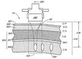
일 실시예에서, 미용 치료에 사용되는 심미적 이미징 및 치료 시스템은 복수의 로케이션에 있는 조직의 초점 깊이로 초음파 이미징 및 초음파 치료를 위해 구성된 초음파 프로브를 포함한다. 일 실시예에서, 초음파 프로브는 초음파 프로브에 결합하기 위해 구성된 트랜스듀서 모듈을 포함하되, 트랜스듀서 모듈은 복수의 로케이션에 있는 조직에 초점 깊이로 초음파 치료를 인가하도록 구성된 초음파 트랜스듀서를 포함한다. 일 실시예에서, 제1 스위치는 초음파 이미징을 제공하는 초음파 이미징 기능을 동작 가능하게 제어한다. 일 실시예에서, 제2 스위치는 초음파 치료를 제공하는 초음파 치료 기능을 동작 가능하게 제어한다. 일 실시예에서, 이동 메커니즘은 개별 열 미용 치료 존의 적어도 하나의 시퀀스 내에서 초음파 치료를 향하게하되, 트랜스듀서 모듈은 제1 스위치, 제2 스위치 및 이동 메커니즘 중 적어도 하나에 동작 가능하게 결합되도록 구성된다. 일 실시예에서, 제어 모듈은 트랜스듀서 모듈을 제어하기 위해 프로세서 및 디스플레이를 포함한다. 일 실시예에서, 트랜스듀서 모듈은 탈착이 가능하다. 예를 들어, 비제한적인 실시예에서의 트랜스듀서는 1.5 mm, 3 mm, 4.5 mm, 6 mm, 3 mm 이하, 1.5 mm와 3 mm 사이, 1.5 mm와 4.5 mm 사이, 4.5 mm 이상, 6 mm 이상의 피부 깊이, 및 0.1 mm -3 mm 범위, 0.1 mm - 4.5 mm 범위, 0.1 mm - 25 mm 범위, 0.1 mm - 100 mm 범위에 속하는 피부 깊이를 위해 구성될 수 있다.In one embodiment, an aesthetic imaging and treatment system used in cosmetic treatment includes an ultrasound probe configured for ultrasound imaging and ultrasound treatment with depth of focus of tissue at a plurality of locations. In one embodiment, an ultrasound probe includes a transducer module configured to couple to the ultrasound probe, wherein the transducer module includes an ultrasound transducer configured to apply ultrasound treatment at a depth of focus to tissue at a plurality of locations. In one embodiment, the first switch operatively controls an ultrasound imaging function that provides ultrasound imaging. In one embodiment, the second switch operatively controls an ultrasound treatment function that provides ultrasound treatment. In one embodiment, the movement mechanism is configured to direct ultrasound treatment within at least one sequence of individual thermal aesthetic treatment zones, wherein the transducer module is operatively coupled to at least one of the first switch, the second switch and the movement mechanism. do. In one embodiment, the control module includes a processor and a display for controlling the transducer module. In one embodiment, the transducer module is removable. For example, a transducer in a non-limiting embodiment may be 1.5 mm, 3 mm, 4.5 mm, 6 mm, 3 mm or less, between 1.5 mm and 3 mm, between 1.5 mm and 4.5 mm, 4.5 mm or more, 6 mm or less. or greater, and skin depths falling within the range of 0.1 mm -3 mm, 0.1 mm - 4.5 mm, 0.1 mm - 25 mm, 0.1 mm - 100 mm.
다양한 실시예에서, 복수의 로케이션은 미용 치료 존 내에 실질적으로 선형 시퀀스로 배치된다. 일 실시예에서, 제1 로케이션 집합은 제1 미용 치료 존 내에 배치되고 제2 로케이션 집합은 제2 미용 치료 존 내에 배치되되, 제1 미용 치료 존과 제2 미용 치료 존은 상이하다. 일 실시예에서, 제1 미용 치료 존은 제1 로케이션 집합의 실질적으로 선형 시퀀스를 포함하며 제2 미용 치료 존은 제2 로케이션 집합의 실질적으로 선형 시퀀스를 포함한다. 일 실시예에서, 트랜스듀서 모듈은 진폭 변조를 이용하여 초음파 치료를 인가하도록 구성되며, 트랜스듀서 모듈는 복수 진폭의 어쿠스틱 세기로 초음파 치료를 방사(emit)하도록 구성된 복수의 부분들을 포함하되, 제1 진폭과 제2 진폭은 상이하다. 일 실시예로, 트랜스듀서 모듈은 초음파 치료 위상 쉬프팅을 인가하도록 구성되며, 트랜스듀서 모듈은 복수 위상의 어쿠스틱 세기로 초음파 치료를 방사하도록 구성된 복수의 부분들을 포함하되, 제1 위상과 제2 위상은 상이하다.In various embodiments, the plurality of locations are disposed in a substantially linear sequence within the cosmetic treatment zone. In one embodiment, the first set of locations is disposed within the first cosmetic treatment zone and the second set of locations is disposed within the second cosmetic treatment zone, wherein the first cosmetic treatment zone and the second cosmetic treatment zone are different. In one embodiment, the first cosmetic treatment zone includes a substantially linear sequence of a first set of locations and the second cosmetic treatment zone includes a substantially linear sequence of a second set of locations. In one embodiment, the transducer module is configured to apply ultrasound treatment using amplitude modulation, the transducer module comprising a plurality of portions configured to emit ultrasound treatment with acoustic intensities of multiple amplitudes, wherein the transducer module comprises a first amplitude and the second amplitude are different. In one embodiment, the transducer module is configured to apply an ultrasound treatment phase shifting, the transducer module comprising a plurality of portions configured to radiate ultrasound treatment with acoustic intensities of a plurality of phases, wherein the first phase and the second phase are different
일 실시예에서, 이동 메커니즘은 동작 메커니즘이다. 다양한 실시예에서, 이동 메커니즘은 트랜스듀서를 모듈 또는 프로브 내에서 이동시키도록 구성된다. 일 실시예에서, 트랜스듀서는 트랜스듀서 홀더에 의해 유지된다. 일 실시예에서, 트랜스듀서 홀더는 선형 베어링, 즉, 트랜스듀서의 반복적인 선형 이동을 보장하는 바(또는 샤프트(shaft))와 같은 동작 구속 베어링을 따라 이동되는 슬리브(sleeve)를 포함한다. 일 실시예에서, 슬리브는 스플라인 샤프트(spline shaft) 주의로 회전하는 것을 방지하지만 동작의 경로가 적절하도록 유지하도록 가이드하는 스플라인 부싱(spline bushing)이다.In one embodiment, the movement mechanism is an action mechanism. In various embodiments, the movement mechanism is configured to move the transducer within the module or probe. In one embodiment, the transducer is held by a transducer holder. In one embodiment, the transducer holder comprises a linear bearing, ie, a sleeve that is moved along a motion constraining bearing such as a bar (or shaft) that ensures repeatable linear movement of the transducer. In one embodiment, the sleeve is a spline bushing that prevents the spline shaft from rotating around, but guides it to keep the path of motion appropriate.
일 실시예에서, 트랜스듀서 홀더는 동작 메커니즘에 의해 구동되며, 동작 메커니즘은 핸드 완드 또는 모듈, 또는 프로브에 위치될 수 있다. 일 실시예에서, 동작 메커니즘(400)은 임의의 하나 이상의 스카치 요크(scotch yoke), 이동 부재, 및 마그네틱 커플링을 포함한다. 일 실시예에서, 마그네틱 커플링은 트랜스듀서가 이동하도록 돕는다. 동작 메커니즘의 이점은 이미징 및/또는 치료 목적을 위한 초음파 트랜스듀서의 효율적이고, 정확하고 정밀한 사용을 제공한다는 점이다. 이러한 종류의 동작 메커니즘이 하우징 내 공간에 고정된 다중 트랜스듀서의 일반적으로 고정된 어레이에 대해 갖는 장점은 고정된 어레이는 고정된 거리만큼 이격되어 있다는 점이다.In one embodiment, the transducer holder is driven by an actuation mechanism, which may be located on a hand wand or module, or probe. In one embodiment, the
컨트롤러의 제어하에 트랜스듀서를 트랙(예를 들어, 선형 트랙)에 배치시킴으로써, 시스템 및 장치의 실시예들은 효율성, 정확성 및 정밀성뿐 아니라 적응성 및 유연성을 제공한다. 이미징 및 치료 포지셔닝이 동작 메커니즘에 의한 제어된 동작을 따라 실시간 및 거의 실시간으로 조정될 수 있다. 동작 메커니즘에 의해 가능해진 점증 조정(incremental adjustment)에 기초한 거의 임의의 레졸루션(resolution)을 선택할 수 있는 능력에 더하여, 이미징이 비정상(abnormality) 또는 치료 간격 및 타게팅을 변경할 필요가 있는 조건을 감지하면, 조정이 이루어질 수 있다. 일 실시예에서, 하나 이상의 센서가 모듈에 포함될 수 있다. 일 실시예에서, 하나 이상의 센서가 모듈에 포함되어 동작 부재와 트랜스듀서 홀더간 기계적 커플링이 실제로 결합되어 있음을 보장할 수 있다. 일 실시예에서, 엔코더가 트랜스듀서 홀더의 상부에 배치될 수 있으며 센서는 모듈의 일부에 위치(located)될 수 있거나, 그 반대일 수 있다(교체됨).By placing the transducer on a track (eg, a linear track) under the control of a controller, embodiments of the system and apparatus provide adaptability and flexibility as well as efficiency, accuracy and precision. Imaging and treatment positioning can be adjusted in real-time and near real-time following controlled action by an action mechanism. In addition to the ability to select virtually any resolution based on incremental adjustments made possible by the action mechanism, if imaging detects abnormalities or conditions that necessitate changing treatment intervals and targeting, Adjustments may be made. In one embodiment, one or more sensors may be included in a module. In one embodiment, one or more sensors may be included in the module to ensure that the mechanical coupling between the motion member and the transducer holder is actually engaged. In one embodiment, the encoder may be placed on top of the transducer holder and the sensor may be located in a portion of the module, or vice versa (replaced).
다양한 실시예에서, 센서는 거대 자기저항 효과(giant magnetoresistive effect; GMR) 또는 홀 효과(Hall Effect) 센서와 같은 마그네틱 센서이며, 엔코더는 마그넷, 마그넷의 집합(collection), 또는 다중폴 마그네틱 스트립이다. 센서는 트랜스듀서 모듈 홈 포지션으로 배치될 수 있다. 일 실시예에서, 센서는 접촉 압력 센서이다. 일 실시예에서, 센서는 장치의 표면에 있는 접촉 압력 센서이며 환자에 있는 장치 또는 트랜스듀서의 포지션을 감지한다. 다양한 실시예에서, 센서는 장치 또는 장치 내 컴포넌트의 포지션을 일차원, 이차원, 또는 삼차원으로 나타내는데 이용될 수 있다. 일 실시예에서, 센서는 장치(또는 그 안의 컴포넌트)와 환자 간의 포지션, 각도, 기울기(tilt), 배향(orientation), 배치(placement), 높이(elevation), 또는 다른 관계를 감지하도록 구성된다. 일 실시예에서, 센서는 광학 센서를 포함한다. 일 실시예에서, 센서는 롤러볼 센서를 포함한다. 일 실시예에서, 센서는 포지션을 일차원, 이차원 및/또는 삼차원으로 표시하도록 구성되어 환자의 피부 또는 조직에 대한 치료 영역들 또는 선들 사이의 거리를 계산한다.In various embodiments, the sensor is a magnetic sensor, such as a giant magnetoresistive effect (GMR) or Hall Effect sensor, and the encoder is a magnet, a collection of magnets, or a multipole magnetic strip. The sensor may be placed in the transducer module home position. In one embodiment, the sensor is a contact pressure sensor. In one embodiment, the sensor is a contact pressure sensor on the surface of the device and senses the position of the device or transducer in the patient. In various embodiments, sensors may be used to represent the position of a device or component within a device in one, two, or three dimensions. In one embodiment, the sensor is configured to sense a position, angle, tilt, orientation, placement, elevation, or other relationship between the device (or a component therein) and the patient. In one embodiment, the sensor comprises an optical sensor. In one embodiment, the sensor comprises a rollerball sensor. In one embodiment, the sensor is configured to display position in one, two and/or three dimensions to calculate the distance between treatment areas or lines relative to the patient's skin or tissue.
동작 메커니즘은 트랜스듀서의 이동에 유용하다고 판단되는 임의의 동작 메커니즘일 수 있다. 여기에 유용한 동작 메커니즘의 다른 실시예는 웜 기어 등을 포함할 수 있다. 다양한 실시예에서, 동작 메커니즘은 모듈(200)에 위치한다. 다양한 실시예에서, 동작 메커니즘은 선형, 회전, 다차원 동작 또는 구동(actuation)을 제공할 수 있으며, 동작은 공간 내 포인트 및/또는 배향의 임의의 집합(collection)도 포함할 수 있다. 동작에 대한 다양한 실시예는, 직선(rectilinear), 원(circular), 타원(elliptical), 원호(arc-like), 나선(spiral), 공간상의 하나 이상의 포인트의 집합, 또는 임의의 1-D, 2-D, 또는 3-D 포지셔널 및 애티튜디널(positional and attitudinal) 동작 실시예를 포함하는 일부 실시예에 따라서 이용될 수 있으나, 이에 한정되지 않는다. 동작 메커니즘의 속도는 고정되거나 사용자에 의해 조정 가능하게 제어될 수 있다. 일 실시예에서, 이미지 시퀀스를 위한 동작 메커니즘의 속도는 치료 시퀀스를 위한 속도와 상이할 수 있다. 일 실시예에서, 동작 메커니즘의 속도는 컨트롤러에 의해 제어될 수 있다.The actuation mechanism may be any actuation mechanism determined to be useful for movement of the transducer. Other embodiments of operating mechanisms useful herein may include worm gears and the like. In various embodiments, the operating mechanism resides in
다양한 실시예에서, 트랜스듀서 모듈은 진폭 변조를 이용하여 초음파 치료를 인가하도록 구성되며, 트랜스듀서 모듈은 복수 진폭의 어쿠스틱 세기로 초음파 치료를 방사하도록 구성된 복수의 부분을 포함하되, 제1 진폭과 제2 진폭은 상이하며, 트랜스듀서 모듈은 초음파 치료 위상 쉬프팅을 인가하도록 구성되며, 트랜스듀서 모듈은 복수 위상의 어쿠스틱 세기로 초음파 치료를 방사하도록 구성된 복수의 부분을 포함하되, 제1 위상과 제2 위상은 상이하다.In various embodiments, the transducer module is configured to apply ultrasound treatment using amplitude modulation, the transducer module comprising a plurality of portions configured to radiate ultrasound treatment with acoustic intensities of multiple amplitudes, wherein the transducer module comprises a first amplitude and a second amplitude. the two amplitudes are different, the transducer module is configured to apply an ultrasound therapy phase shifting, the transducer module comprising a plurality of portions configured to radiate ultrasound therapy with acoustic intensities of multiple phases, a first phase and a second phase is different
일 실시예에서, 복수의 위상은 이산 위상 값을 포함한다. 일 실시예에서, 트랜스듀서 모듈은 압전 물질을 포함하며, 트랜스듀서 모듈의 복수의 부분들은 트랜스듀서 모듈에 인가된 전기장에 대한 응답으로 복수의 상응하는 압전 물질 변화를 생성하도록 구성된다. 일 실시예에서, 복수의 압전 물질 변화는 압전 물질의 확장 및 압전 물질의 수축 중 적어도 하나를 포함한다. 일 실시예에서, 트랜스듀서 모듈은 초음파 치료를 둘 이상의 진폭의 어쿠스틱 세기로 방사하도록 구성된 적어도 한 부분을 포함하되, 트랜스듀서 모듈의 적어도 한 부분에 의해 방사된 초음파 치료의 진폭은 시간에 걸쳐 변화한다.In one embodiment, the plurality of phases comprises discrete phase values. In one embodiment, the transducer module comprises a piezoelectric material, and the plurality of portions of the transducer module are configured to produce a plurality of corresponding piezoelectric material changes in response to an electric field applied to the transducer module. In an embodiment, the plurality of piezoelectric material changes include at least one of an expansion of the piezoelectric material and a contraction of the piezoelectric material. In one embodiment, the transducer module includes at least one portion configured to radiate ultrasound treatment with acoustic intensities of two or more amplitudes, wherein the amplitude of the ultrasound treatment radiated by the at least one portion of the transducer module varies over time. .
일 실시예에서, 이동 메커니즘은 복수의 개별 열 미용 치료 존 사이에 가변 간격을 제공하도록 프로그래밍된다. 일 실시예에서, 개별 열 미용 치료 존의 시퀀스는 약 0.01 mm부터 약 25 mm까지 범위의 치료 간격(예를 들어, 1 mm, 1.5 mm, 2 mm, 1-5 mm)을 가진다. 일 실시예에서, 제1 및 제2 스위치는 사용자 조작 버튼 또는 키를 포함한다. 일 실시예에서, 제1 및 제2 스위치 중 적어도 하나는 제어 모듈에 의해 작동된다.In one embodiment, the movement mechanism is programmed to provide variable spacing between a plurality of individual thermal cosmetic treatment zones. In one embodiment, the sequence of individual thermal cosmetic treatment zones has a treatment spacing ranging from about 0.01 mm to about 25 mm (eg, 1 mm, 1.5 mm, 2 mm, 1-5 mm). In one embodiment, the first and second switches include user operated buttons or keys. In one embodiment, at least one of the first and second switches is actuated by the control module.
일 실시예에서, 치료 기능은 페이스 리프트, 브로우 리프트, 친 리프트, 눈 치료, 주름 축소, 흉터 축소, 화상 치료, 문신 제거, 스킨 타이트닝, 정맥 제거, 정맥 축소, 땀샘 치료, 다한증 치료, 주근깨 제거, 지방 치료, 질 회춘, 및 여드름 치료 중 적어도 하나이다. 일 실시예에서, 트랜스듀서 모듈은 약 1W에서 약 100W 범위(예를 들어, 5-40 W, 10-50 W, 25-35 W) 그리고 약1 MHz에서 약 10 MHz 주파수 범위로 초음파 치료의 어쿠스틱 파워를 제공하도록 구성되어 조직을 열적으로 가열하여 응고시킨다. 일 실시예에서, 어쿠스틱 파워는 약 1W에서 약 100W 범위 그리고 약1 MHz에서 약 12 MHz 주파수 범위(예를 들어, 4MHz, 7 MHz, 10MHz, 4-10MHz)이거나, 약 10W에서 약 50W 범위 그리고 약3 MHz에서 약 8 MHz 주파수 범위일 수 있다. 일 실시예에서, 어쿠스틱 파워 및 주파수는 약 4.3 MHz에서 40 W 및 약 7.5 MHz에서 30 W이다. 이 어쿠스틱 파워에 의해 생성된 어쿠스틱 에너지는 약 0.01 줄(J)에서 약 10 J사이 또는 약 2 J에서 약 5 J 사이일 수 있다. 일 실시예에서, 어쿠스틱 에너지는 3 J 이하의 범위에 있다.In one embodiment, the treatment function is a face lift, brow lift, chin lift, eye treatment, wrinkle reduction, scar reduction, burn treatment, tattoo removal, skin tightening, vein removal, vein reduction, sweat gland treatment, hyperhidrosis treatment, freckle removal, at least one of fat treatment, vaginal rejuvenation, and acne treatment. In one embodiment, the transducer module is configured for acoustic treatment of ultrasound therapy in a range of about 1 W to about 100 W (eg, 5-40 W, 10-50 W, 25-35 W) and a frequency range of about 1 MHz to about 10 MHz. configured to provide power to thermally heat the tissue to coagulate. In one embodiment, the acoustic power is in the range of about 1 W to about 100 W and about 1 MHz to about 12 MHz frequency range (eg, 4 MHz, 7 MHz, 10 MHz, 4-10 MHz), or about 10 W to about 50 W and about It may range from 3 MHz to about 8 MHz frequency. In one embodiment, the acoustic power and frequency are 40 W at about 4.3 MHz and 30 W at about 7.5 MHz. The acoustic energy produced by this acoustic power may be between about 0.01 joules (J) and about 10 J, or between about 2 J and about 5 J. In one embodiment, the acoustic energy is in the range of 3 J or less.
다양한 실시예에서, 다초점 초음파 치료 시스템은 초음파 치료를 제공하는 초음파 치료 기능을 동작 가능하게 제어하는 제어 장치 및 개별 열 미용 치료 존의 시퀀스로 초음파 치료를 향하게하는 핸드 완드를 포함한다. 핸드 완드는 로케이션에 있는 조직에 초점 깊이로 초음파 치료를 인가하는 트랜스듀서를 포함하며, 로케이션은 열 미용 치료 존 내에 포지션되되, 트랜스듀서는 복수의 로케이션에 있는 조직에 초점 깊이로 초음파 치료를 동시에 인가하도록 더 구성된다.In various embodiments, a multifocal ultrasound treatment system includes a control device for operatively controlling an ultrasound treatment function to provide ultrasound treatment and a hand wand for directing ultrasound treatment into a sequence of individual thermal cosmetic treatment zones. The hand wand includes a transducer for applying ultrasound treatment at a depth of focus to tissue at a location, the location being positioned within a thermal cosmetic treatment zone, wherein the transducer simultaneously applies ultrasound treatment at a depth of focus to tissue at a plurality of locations further configured to do so.
다양한 실시예에서, 심미적 이미징 및 다초점 치료 시스템은 복수의 로케이션에 있는 조직에 초점 깊이로 진폭 변조 폴링 및 위상 쉬프팅 중 적어도 하나로 초음파 치료를 인가하는 초음파 트랜스듀서를 포함하는 초음파 프로브 및 초음파 프로브에 결합되어 초음파 트랜스듀서를 제어하는 제어 모듈을 포함한다. 일 실시예에서, 복수의 로케이션은 미용 치료 존 내에서 실질적으로 선형 시퀀스로 배치된다. 일 실시예에서, 제1 로케이션 집합은 제1 미용 치료 존 내에 배치되고 제2 로케이션 집합은 제2 미용 치료 존 내에 배치되되, 제1 미용 치료 존과 제2 미용 치료 존은 상이하다. 일 실시예에서, 제1 미용 치료 존은 제1 로케이션 집합의 실질적으로 선형 시퀀스를 포함하며 제2 미용 치료 존은 제2 로케이션 집합의 실질적으로 선형 시퀀스를 포함한다. 일 실시예에서, 초음파 트랜스듀서는 진폭 변조를 이용하여 초음파 치료를 인가하도록 구성되며, 초음파 트랜스듀서는 복수 진폭의 어쿠스틱 세기로 초음파 치료를 방사하도록 구성된 복수의 부분을 포함하되, 제1 진폭과 제2 진폭은 상이하다. 일 실시예에서, 초음파 트랜스듀서는 초음파 치료 위상 쉬프팅을 인가하도록 구성되며, 초음파 트랜스듀서는 복수 위상의 어쿠스틱 세기로 초음파 치료를 방사하도록 구성된 복수의 부분을 포함하되, 제1 위상과 제2 위상은 상이하다. 일 실시예에서, 초음파 트랜스듀서는 진폭 변조를 이용하여 초음파 치료를 인가하도록 구성되며, 초음파 트랜스듀서는 복수 진폭의 어쿠스틱 세기로 초음파 치료를 방사하도록 구성된 복수의 부분을 포함하되, 제1 진폭과 제2 진폭은 상이하며, 초음파 트랜스듀서는 초음파 치료 위상 쉬프팅을 인가하도록 구성되며, 초음파 트랜스듀서는 복수 위상의 어쿠스틱 세기로 초음파 치료를 방사하도록 구성된 복수의 부분을 포함하되, 제1 위상과 제2 위상은 상이하다. 일 실시예에서, 복수의 위상은 이산 위상 값을 포함한다.In various embodiments, an aesthetic imaging and multifocal treatment system is coupled to an ultrasound probe and an ultrasound probe comprising an ultrasound transducer that applies ultrasound treatment to tissue at a plurality of locations with at least one of amplitude-modulated polling and phase shifting to a depth of focus. and a control module for controlling the ultrasonic transducer. In one embodiment, the plurality of locations are arranged in a substantially linear sequence within the cosmetic treatment zone. In one embodiment, the first set of locations is disposed within the first cosmetic treatment zone and the second set of locations is disposed within the second cosmetic treatment zone, wherein the first cosmetic treatment zone and the second cosmetic treatment zone are different. In one embodiment, the first cosmetic treatment zone includes a substantially linear sequence of a first set of locations and the second cosmetic treatment zone includes a substantially linear sequence of a second set of locations. In one embodiment, the ultrasound transducer is configured to apply ultrasound treatment using amplitude modulation, the ultrasound transducer comprising a plurality of portions configured to radiate ultrasound treatment with acoustic intensities of multiple amplitudes, a first amplitude and a second amplitude The two amplitudes are different. In one embodiment, the ultrasound transducer is configured to apply ultrasound treatment phase shifting, the ultrasound transducer comprising a plurality of portions configured to radiate ultrasound treatment with acoustic intensities of multiple phases, wherein the first phase and the second phase are different In one embodiment, the ultrasound transducer is configured to apply ultrasound treatment using amplitude modulation, the ultrasound transducer comprising a plurality of portions configured to radiate ultrasound treatment with acoustic intensities of multiple amplitudes, a first amplitude and a second amplitude the two amplitudes are different, the ultrasound transducer is configured to apply an ultrasound treatment phase shifting, the ultrasound transducer comprising a plurality of portions configured to radiate ultrasound treatment with acoustic intensities of multiple phases, a first phase and a second phase is different In one embodiment, the plurality of phases comprises discrete phase values.
일 실시예에서, 초음파 트랜스듀서는 압전 물질을 포함하며, 초음파 트랜스듀서의 복수의 부분들은 초음파 트랜스듀서에 인가된 전기장에 대한 응답으로 복수의 상응하는 압전 물질 변화를 생성하도록 구성된다. 일 실시예에서, 복수의 압전 물질 변화는 압전 물질의 확장 및 압전 물질의 수축 중 적어도 하나를 포함한다. 일 실시예에서, 초음파 트랜스듀서는 초음파 치료를 둘 이상의 진폭의 어쿠스틱 세기로 방사하도록 구성된 적어도 한 부분을 포함하되, 압전 물질의 적어도 한 부분에 의해 방사된 초음파 치료의 진폭은 시간에 걸쳐 변화한다. 일 실시예에서, 시스템은 복수의 개별 미용 치료 존 사이에 가변 간격을 제공하도록 프로그래밍된 이동 메커니즘을 또한 포함한다. 일 실시예에서, 개별 미용 치료 존의 시퀀스는 약 0.01 mm부터 약 25 mm까지 범위의 치료 간격을 가진다. 다양한 실시예에서, 초음파 치료는 페이스 리프트, 브로우 리프트, 친 리프트, 눈 치료, 주름 축소, 흉터 축소, 화상 치료, 문신 제거, 스킨 타이트닝, 정맥 제거, 정맥 축소, 땀샘 치료, 다한증 치료, 주근깨 제거, 지방 치료, 질 회춘, 및 여드름 치료 중 적어도 하나이다. 일 실시예에서, 초음파 트랜스듀서는 약 1W에서 약 100W 범위 그리고 약1 MHz에서 약 10 MHz 주파수 범위로 초음파 치료의 어쿠스틱 파워를 제공하도록 구성되어 조직을 열적으로 가열하여 응고시킨다.In one embodiment, the ultrasonic transducer comprises a piezoelectric material, and the plurality of portions of the ultrasonic transducer are configured to produce a plurality of corresponding piezoelectric material changes in response to an electric field applied to the ultrasonic transducer. In an embodiment, the plurality of piezoelectric material changes include at least one of an expansion of the piezoelectric material and a contraction of the piezoelectric material. In one embodiment, the ultrasound transducer comprises at least one portion configured to radiate ultrasound treatment with acoustic intensities of two or more amplitudes, wherein the amplitude of the ultrasound treatment radiated by the at least one portion of the piezoelectric material varies over time. In one embodiment, the system also includes a movement mechanism programmed to provide variable spacing between the plurality of individual cosmetic treatment zones. In one embodiment, the sequence of individual cosmetic treatment zones has a treatment spacing ranging from about 0.01 mm to about 25 mm. In various embodiments, ultrasound treatment is a face lift, brow lift, chin lift, eye treatment, wrinkle reduction, scar reduction, burn treatment, tattoo removal, skin tightening, vein removal, vein reduction, sweat gland treatment, hyperhidrosis treatment, freckle removal, at least one of fat treatment, vaginal rejuvenation, and acne treatment. In one embodiment, the ultrasound transducer is configured to provide the acoustic power of ultrasound treatment in a frequency range of about 1 W to about 100 W and a frequency range of about 1 MHz to about 10 MHz to thermally heat and coagulate tissue.
일 실시예에서, 치료 시스템은 초음파 치료를 제공하는 초음파 치료 기능을 동작 가능하게 제어하는 제어 장치 및 개별 열 미용 치료 존의 시퀀스로 초음파 치료를 향하게하는 핸드 완드를 포함한다. 일 실시예에서, 핸드 완드는 복수의 로케이션에 있는 조직에 초점 깊이로 초음파 치료를 동시에 인가하는 트랜스듀서를 포함한다.In one embodiment, the treatment system includes a control device for operatively controlling an ultrasound treatment function providing ultrasound treatment and a hand wand for directing ultrasound treatment into a sequence of individual thermal cosmetic treatment zones. In one embodiment, the hand wand includes a transducer that simultaneously applies ultrasound treatment at a depth of focus to tissue at a plurality of locations.
다양한 실시예에서, 의사에 의해서 수행되지 않는 미용 시술을 수행하는 시스템은, 트랜스듀서 모듈을 포함하는 초음파 프로브를 포함한다. 일 실시예에서, 초음파 프로브는 복수의 로케이션에 있는 조직에 초점 깊이로 진폭 변조 폴링 및 위상 쉬프팅 중 적어도 하나로 초음파 치료를 인가하도록 구성된 초음파 트랜스듀서를 포함한다. 일 실시예에서, 초음파 프로브는 어쿠스틱 이미징을 제어하는 제1 스위치를 포함하고, 초음파 프로브는 복수의 개별 미용 치료 존을 유발하는 어쿠스틱 치료를 제어하는 제2 스위치를 포함하며, 초음파 프로브는 개별 미용 치료 존 사이에 바람직한 간격을 제공하는 이동 메커니즘을 포함한다.In various embodiments, a system for performing cosmetic procedures not performed by a physician includes an ultrasound probe including a transducer module. In one embodiment, the ultrasound probe includes an ultrasound transducer configured to apply ultrasound treatment to tissue at a plurality of locations with at least one of amplitude modulated polling and phase shifting to a depth of focus. In one embodiment, the ultrasound probe comprises a first switch to control acoustic imaging, the ultrasound probe comprises a second switch to control an acoustic treatment causing a plurality of individual cosmetic treatment zones, and the ultrasound probe comprises a second switch to control the individual cosmetic treatment zones. Includes a movement mechanism to provide desirable spacing between zones.
다양한 실시예에서, 미용 치료에 사용되는 심미적 이미징 및 치료 시스템은 초음파 프로브를 포함한다. 일 실시예에서, 트랜스듀서 모듈은 초음파 치료를 음파적으로 투명한(acoustically transparent) 부재에 있는 개구를 통해 인가하여 조직내 초점 깊이로 열 응고 점을 형성하도록 구성된 초음파 트랜스듀서를 포함한다. 일 실시예에서, 제1 스위치는 초음파 이미징을 제공하는 초음파 이미징 기능을 동작 가능하게 제어하고, 제2 스위치는 초음파 치료를 제공하는 초음파 치료 기능을 동작 가능하게 제어하며, 이동 메커니즘은 개별 열 미용 치료 존의 적어도 하나의 시퀀스 내에서 초음파 치료를 향하게한다. 다양한 실시예에서, 트랜스듀서 모듈은 초음파 이미징과 초음파 치료를 위해 구성되고, 트랜스듀서 모듈은 초음파 프로브에 결합하기 위해 구성되며, 트랜스듀서 모듈은 제1 스위치, 제2 스위치 및 이동 메커니즘 중 적어도 하나에 동작 가능하게 결합되도록 구성된다. 일 실시예에서, 제어 모듈은 트랜스듀서 모듈을 제어하기 위해 프로세서 및 디스플레이를 포함한다.In various embodiments, an aesthetic imaging and treatment system used in cosmetic treatment includes an ultrasound probe. In one embodiment, the transducer module includes an ultrasound transducer configured to apply ultrasound treatment through an opening in an acoustically transparent member to form a thermal coagulation point at a focal depth in the tissue. In one embodiment, the first switch operatively controls an ultrasound imaging function providing ultrasound imaging, the second switch operatively controlling an ultrasound treatment function providing ultrasound treatment, and wherein the movement mechanism operatively controls the individual thermal cosmetic treatment Direct ultrasound therapy within at least one sequence of zones. In various embodiments, the transducer module is configured for ultrasound imaging and ultrasound therapy, the transducer module is configured to couple to an ultrasound probe, and the transducer module is configured to be connected to at least one of the first switch, the second switch, and the movement mechanism. configured to be operatively coupled. In one embodiment, the control module includes a processor and a display for controlling the transducer module.
일 실시예에서, 복수의 로케이션은 미용 치료 존 내에서 실질적으로 선형 시퀀스로 배치된다. 일 실시예에서, 제1 로케이션 집합은 제1 미용 치료 존 내에 배치되고 제2 로케이션 집합은 제2 미용 치료 존 내에 배치되되, 제1 미용 치료 존과 제2 미용 치료 존은 상이하다. 일 실시예에서, 제1 미용 치료 존은 제1 로케이션 집합의 실질적으로 선형 시퀀스를 포함하며 제2 미용 치료 존은 제2 로케이션 집합의 실질적으로 선형 시퀀스를 포함한다. 일 실시예에서, 이동 메커니즘은 복수의 개별 열 미용 치료 존 사이에 고정된 간격을 제공하도록 구성된다. 일 실시예에서, 개별 열 미용 치료 존의 시퀀스는 약 0.01 mm부터 약 25 mm까지 범위의 치료 간격을 가진다. 일 실시예에서, 제1 및 제2 스위치는 사용자 조작 버튼 또는 키를 포함한다. 일 실시예에서, 치료 기능은 페이스 리프트, 브로우 리프트, 친 리프트, 눈 치료, 주름 축소, 흉터 축소, 화상 치료, 문신 제거, 스킨 타이트닝, 정맥 제거, 정맥 축소, 땀샘 치료, 다한증 치료, 주근깨 제거, 지방 치료, 질 회춘, 및 여드름 치료 중 적어도 하나이다. 일 실시예에서, 트랜스듀서 모듈은 약 1W에서 약 100W 범위 그리고 약1 MHz에서 약 10 MHz 주파수 범위로 초음파 치료의 어쿠스틱 파워를 제공하도록 구성되어 조직을 열적으로 가열하여 응고시킨다.In one embodiment, the plurality of locations are arranged in a substantially linear sequence within the cosmetic treatment zone. In one embodiment, the first set of locations is disposed within the first cosmetic treatment zone and the second set of locations is disposed within the second cosmetic treatment zone, wherein the first cosmetic treatment zone and the second cosmetic treatment zone are different. In one embodiment, the first cosmetic treatment zone includes a substantially linear sequence of a first set of locations and the second cosmetic treatment zone includes a substantially linear sequence of a second set of locations. In one embodiment, the movement mechanism is configured to provide a fixed spacing between the plurality of individual thermal cosmetic treatment zones. In one embodiment, the sequence of individual thermal cosmetic treatment zones has a treatment spacing ranging from about 0.01 mm to about 25 mm. In one embodiment, the first and second switches include user operated buttons or keys. In one embodiment, the treatment function is a face lift, brow lift, chin lift, eye treatment, wrinkle reduction, scar reduction, burn treatment, tattoo removal, skin tightening, vein removal, vein reduction, sweat gland treatment, hyperhidrosis treatment, freckle removal, at least one of fat treatment, vaginal rejuvenation, and acne treatment. In one embodiment, the transducer module is configured to provide acoustic power of ultrasound therapy in a frequency range of about 1 W to about 100 W and a frequency range of about 1 MHz to about 10 MHz to thermally heat and coagulate tissue.
다양한 실시예에서, 치료 시스템은 피부 표면 아래 상이한 깊이에 초음파 치료를 제공하는 초음파 치료 기능을 동작 가능하게 제어하는 제어 장치, 및 피부 표면 아래 둘 이상의 초점 깊이로 초음파 치료를 향하게하도록 구성된 핸드 완드를 포함하며, 핸드 완드는 피부 표면 아래 둘 이상의 초점 깊이로 초음파 치료를 인가하도록 구성된 적어도 두 개의 상호 교체 가능한 트랜스듀서 모듈을 연결하도록 구성되되, 트랜스모듈 각각은 열 응고점(TCP)의 하나 이상의 시퀀스를 생성하도록 구성된다.In various embodiments, a treatment system includes a control device operatively controlling an ultrasound treatment function to provide ultrasound treatment at different depths below the skin surface, and a hand wand configured to direct ultrasound treatment at two or more focal depths below the skin surface. wherein the hand wand is configured to couple at least two interchangeable transducer modules configured to apply ultrasound treatment to at least two focal depths below the skin surface, each of the transducer modules to generate one or more sequences of thermal coagulation points (TCPs); is composed
일 실시예에서, 시스템은 피부 표면 아래 적어도 하나의 깊이에서의 이미지를 제공하도록 구성된 이미징 트랜스듀서를 또한 포함한다. 일 실시예에서, 시스템은 개별 이산 병변의 시퀀스를 선형 시퀀스로 배치하는 이동 메커니즘을 또한 포함한다. 일 실시예에서, 트랜스듀서 모듈은 약 1W에서 약 100W 범위 그리고 약1 MHz에서 약 10 MHz 주파수 범위로 초음파 치료를 제공하도록 구성된 적어도 하나의 트랜스듀서 모듈을 포함한다. 일 실시예에서, 트랜스듀서 모듈은 3 mm의 깊이로 치료를 제공하도록 구성된 하나의 트랜스듀서 모듈을 포함한다. 일 실시예에서, 트랜스듀서 모듈은 4.5 mm의 깊이로 치료를 제공하도록 구성된 하나의 트랜스듀서 모듈을 포함한다.In one embodiment, the system also includes an imaging transducer configured to provide an image at at least one depth below the skin surface. In one embodiment, the system also includes a movement mechanism for placing the sequence of individual discrete lesions in a linear sequence. In one embodiment, the transducer module comprises at least one transducer module configured to provide ultrasound therapy in a range of about 1 W to about 100 W and a frequency range of about 1 MHz to about 10 MHz. In one embodiment, the transducer module comprises one transducer module configured to provide treatment to a depth of 3 mm. In one embodiment, the transducer module comprises one transducer module configured to provide treatment to a depth of 4.5 mm.
일 실시예에서, 적어도 두 개의 상호 교체 가능한 트랜스듀서 모듈은 피부 표면 아래 제1 초점 깊이에서 제1 치료 변환 소자(therapeutic transduction element)로 치료하도록 구성된 제1 상호 교체 가능한 트랜스듀서 모듈을 포함하고, 적어도 두 개의 상호 교체 가능한 트랜스듀서 모듈은 피부 표면 아래 제2 초점 깊이에서 제2 치료 변환 소자로 치료하도록 구성된 제2 상호 교체 가능한 트랜스듀서 모듈을 포함하되, 핸드 완드는 한 번에 제1 상호 교체 가능한 트랜스듀서 모듈 및 제2 상호 교체 가능한 트랜스듀서 모듈 중 하나를 연결하도록 구성되고, 시스템은 피부 표면 아래 제1 초점 깊이의 제1 이미지 및 피부 표면 아래 제2 초점 깊이의 제2 이미지를 보여주는 디스플레이를 포함한다.In one embodiment, the at least two interchangeable transducer modules comprise a first interchangeable transducer module configured to treat with a first therapeutic transduction element at a first focal depth below the skin surface, wherein at least The two interchangeable transducer modules include a second interchangeable transducer module configured to treat with a second treatment conversion element at a second focal depth below the skin surface, wherein the hand wand at a time includes a first interchangeable transducer module. configured to couple one of the transducer module and the second interchangeable transducer module, the system comprising a display showing a first image at a first depth of focus below the skin surface and a second image at a second depth of focus below the skin surface .
일 실시예에서, 핸드 완드는 한 번에 적어도 두 개의 상호 교체 가능한 트랜스듀서 모듈 중 하나를 연결하도록 구성되며, 적어도 두 개의 상호 교체 가능한 트랜스듀서 모듈은 피부 표면 아래 제1 초점 깊이에서 단일 제1 초음파 치료 소자로 치료하도록 구성된 제1 모듈, 및 피부 표면 아래 제2 초점 깊이에서 단일 제2 초음파 치료 소자로 치료하도록 구성된 제2 모듈을 포함한다. 일 실시예에서, 열 응고점의 하나 이상의 시퀀스의 생성은 열 응고점의 다중 선형 시퀀스의 생성을 포함한다.In one embodiment, the hand wand is configured to couple one of the at least two interchangeable transducer modules at a time, wherein the at least two interchangeable transducer modules are configured to provide a single first ultrasound at a first focal depth below the skin surface. a first module configured to treat with a treatment element, and a second module configured to treat with a single second ultrasound treatment element at a second focal depth below the skin surface. In one embodiment, generating the one or more sequences of thermal setting points comprises generating multiple linear sequences of thermal setting points.
일 실시예에서, 이미징 트랜스듀서는 피부 표면 아래 적어도 한 깊이의 이미지를 제공하도록 구성되되, 개별 열 미용 치료 존은 개별 이산 병변이며, 개별 이산 병변의 시퀀스를 선형 시퀀스로 배치하는 이동 메커니즘을 더 포함하되, 트랜스듀서 모듈은 약 1W에서 약 100W 범위 그리고 약1 MHz에서 약 10 MHz 주파수 범위로 초음파 치료를 제공하도록 구성된 적어도 하나의 트랜스듀서 모듈을 포함하고, 트랜스듀서 모듈은 3 mm또는 4.5 mm 의 깊이로 치료를 제공하도록 구성된 하나의 트랜스듀서 모듈을 포함하며, 치료 기능은 페이스 리프트, 브로우 리프트, 친 리프트, 눈 치료, 주름 축소, 흉터 축소, 화상 치료, 문신 제거, 스킨 타이트닝, 정맥 제거, 정맥 축소, 땀샘 치료, 다한증 치료, 주근깨 제거, 지방 치료, 질 회춘, 및 여드름 치료 중 적어도 하나이다.In one embodiment, the imaging transducer is configured to provide an image of at least one depth below the skin surface, wherein the individual thermal cosmetic treatment zones are individual discrete lesions, and further comprising a movement mechanism for placing the sequence of individual discrete lesions in a linear sequence. wherein the transducer module comprises at least one transducer module configured to provide ultrasound therapy in a frequency range of about 1 W to about 100 W and a frequency range of about 1 MHz to about 10 MHz, the transducer module having a depth of 3 mm or 4.5 mm contains one transducer module configured to provide treatment with , sweat gland treatment, hyperhidrosis treatment, freckle removal, fat treatment, vaginal rejuvenation, and acne treatment.
여기에 설명된 일부 실시예에서, 시술은 전적으로 미용 시술이지 의료 행위가 아니다. 예를 들어, 일 실시예에서, 여기에 설명된 방법은 의사에 의해서 수행될 필요가 없으며, 스파 또는 다른 심미적 기관에서 수행될 수 있다. 일부 실시예에서, 시스템은 피부의 비침습적 미용 치료를 위해서 이용될 수 있다.In some embodiments described herein, the procedure is an entirely cosmetic procedure and not a medical practice. For example, in one embodiment, the methods described herein need not be performed by a physician, but may be performed at a spa or other aesthetic institution. In some embodiments, the system may be used for non-invasive cosmetic treatment of the skin.
이상에서 요약되고 이하에서 상세히 제시되는 방법은 의료진에 의해 취해진 특정 행위를 설명하나, 이들 다른 사람에 의한 행위의 지시를 또한 포함할 수 있음을 이해하여야 한다. 그러므로, "트랜스듀서 모듈을 초음파 프로브에 결합"하는 것과 같은 행위는 "트랜스듀서 모듈을 초음파 프로브에 결합을 지시"하는 것을 포함한다.While the methods summarized above and set forth in detail below describe specific actions taken by medical personnel, it should be understood that these may also include instructions for actions by other persons. Therefore, an action such as “coupling the transducer module to the ultrasound probe” includes “instructing the coupling of the transducer module to the ultrasound probe”.
더욱이, 적용성의 영역은 여기에서 제공된 설명으로부터 명확해질 수 있다. 설명과 특정 예들은 설명의 목적으로만 의도된 것이며 여기에 개시된 실시예의 범위를 한정하기 위한 것이 아님을 이해하여야 한다.Moreover, areas of applicability may become apparent from the description provided herein. It is to be understood that the description and specific examples are intended for illustrative purposes only and are not intended to limit the scope of the embodiments disclosed herein.
여기에 설명된 도면은 예시를 위한 것일 뿐 본 명세서의 범위를 제한하기 위한 것이 아니다. 본 발명의 실시예들은 상세한 설명 및 첨부한 도면으로부터 충분히 이해될 수 있다.
도 1은 본 발명의 다양한 실시예에 따른 초음파 시스템의 개요도이다.
도 2는 본 발명의 다양한 실시예에 따른 관심 영역에 결합된 초음파 시스템을 개략적으로 도시한 도면이다.
도 3은 본 발명의 다양한 실시예에 따른 트랜스듀서의 부분 단면도를 개략적으로 도시하고 있다.
도 4는 본 발명의 다양한 실시예에 따른 초음파 시스템의 측면 부분 단면도이다.
도 5a 내지 5d는 본 발명의 일부 실시예에 따른 다양한 트랜스듀서에 대한 초점에 도달하기 위한 시간 지연을 도시한 그래프이다.
도 6a 내지 6c는 본 발명의 일부 실시예에 따른 다양한 트랜스듀서에 대한 초점에 도달하기 위한 시간 지연을 도시한 그래프이다.
도 7a 내지 7c는 본 발명의 일부 실시예에 따른 다양한 트랜스듀서에 대한 초점에 도달하기 위한 양자화된 위상 지연을 도시한 그래프이다.
도 8a 내지 8b는 본 발명의 일부 실시예에 따른 다양한 트랜스듀서에 대한 초점에 도달하기 위한 양자화된 위상 지연 프로파일을 도시한 그래프이다.
도 9는 본 발명의 실시예에 따른 분극된 압전 물질의 특성을 개략적으로 나타낸 도면이다.
도 10a 내지 10b는 본 발명의 일부 실시예에 따른 진폭 변조의 근사화를 설명하기 위한 그래프이다.
도 11a 내지 11h는 본 발명의 일부 실시예에 따른 변조 함수 및 대응하는 세기 분포를 개략적으로 도시한 그래프이다.
도 12a 내지 12d는 본 발명의 일부 실시예에 따른 변조 함수 및 대응하는 세기 분포를 개략적으로 도시한 그래프이다.
도 13은 본 발명의 실시예에 따른 2-위상 시스템의 개요도이다.
도 14는 본 발명의 실시예에 따른 선택 가능한, 4 위상 시스템의 개요도이다.
도 15는 본 발명의 실시예에 따른 이산 페이즈 시스템의 성능을 나타낸 그래프이다.
도 16a 내지 16b는 본 발명의 일부 실시예에 따른 다양한 초첨에서의 이산 페이즈 시스템의 성능을 나타낸 그래프이다.
도 17a 내지 17d는 본 발명의 일부 실시예에 따른 하이브리드 시스템의 개요도 및 그 성능을 나타낸 그래프이다.
도 18은 본 발명의 실시예에 따른 2-위상 선택 가능 시스템의 개요도이다.
도 19a 내지 19c는 본 발명의 실시예에 따른 초점 전 세기 분포 그래프이다.
도 20a 내지 20c는 본 발명의 실시예에 따른 초점에서의 세기 분포 그래프이다.
도 21은 본 발명의 실시예에 따른 진폭 변조 조리개 패턴의 개요도이다.
도 22a 내지 22c는 본 발명의 실시예에 따른 진폭 변조 조리개로부터의 초점 전 세기 분포 그래프이다.
도 23a 내지 23c는 본 발명의 실시예에 따른 진폭 변조 조리개로부터의 초점에서의 세기 분포 그래프이다.
도 24는 본 발명의 실시예에 따른 상태가 변경되는 진폭 변조 조리개 패턴의 개요도이다.
도 25a 내지 25d는 본 발명의 실시예에 따른 상태가 변경되는 진폭 변조 조리개로부터의 초점 전 세기 분포 그래프이다.
도 26a 내지 26c는 본 발명의 실시예에 따른 상태가 변경되는 진폭 변조 조리개로부터의 초점에서의 세기 분포 그래프이다.
도 27a는 본 발명의 실시예에 따른 두 개의 변경되는 레벨을 가진 진폭 변조 조리개의 개요도이다.
도 27b는 본 발명의 실시예에 따른 도 27a 개요도의 상태 천이 테이블이다.
도 28a는 본 발명의 실시예에 따른 세 개의 변경되는 레벨을 가진 진폭 변조 조리개의 개요도이다.
도 28b는 본 발명의 실시예에 따른 도 28a 개요도의 상태 천이 테이블이다.
도 29a는 본 발명의 실시예에 따른 네 개의 변경되는 레벨을 가진 진폭 변조 조리개의 개요도이다.
도 29b는 본 발명의 실시예에 따른 도 29a 개요도의 상태 천이 테이블이다.The drawings described herein are for illustrative purposes only and are not intended to limit the scope of the present specification. Embodiments of the present invention can be fully understood from the detailed description and accompanying drawings.
1 is a schematic diagram of an ultrasound system according to various embodiments of the present disclosure;
2 is a diagram schematically illustrating an ultrasound system coupled to a region of interest according to various embodiments of the present disclosure.
3 schematically illustrates a partial cross-sectional view of a transducer according to various embodiments of the present invention.
4 is a side partial cross-sectional view of an ultrasound system according to various embodiments of the present disclosure;
5A-5D are graphs illustrating the time delay for reaching focus for various transducers in accordance with some embodiments of the present invention.
6A-6C are graphs illustrating time delays for reaching focus for various transducers in accordance with some embodiments of the present invention.
7A-7C are graphs illustrating quantized phase delays for reaching focus for various transducers in accordance with some embodiments of the present invention.
8A-8B are graphs illustrating quantized phase delay profiles for reaching focus for various transducers in accordance with some embodiments of the present invention.
9 is a diagram schematically illustrating characteristics of a polarized piezoelectric material according to an embodiment of the present invention.
10A to 10B are graphs for explaining approximation of amplitude modulation according to some embodiments of the present invention.
11A-11H are graphs schematically illustrating modulation functions and corresponding intensity distributions in accordance with some embodiments of the present invention.
12A-12D are graphs schematically illustrating modulation functions and corresponding intensity distributions in accordance with some embodiments of the present invention.
13 is a schematic diagram of a two-phase system according to an embodiment of the present invention;
14 is a schematic diagram of a selectable, four-phase system in accordance with an embodiment of the present invention.
15 is a graph showing the performance of a discrete phase system according to an embodiment of the present invention.
16A-16B are graphs illustrating the performance of a discrete phase system at various focal points in accordance with some embodiments of the present invention.
17A to 17D are a schematic diagram of a hybrid system according to some embodiments of the present invention and a graph showing its performance.
18 is a schematic diagram of a two-phase selectable system according to an embodiment of the present invention.
19A to 19C are pre-focus intensity distribution graphs according to an embodiment of the present invention.
20A to 20C are graphs of intensity distribution at a focal point according to an embodiment of the present invention.
21 is a schematic diagram of an amplitude modulation diaphragm pattern according to an embodiment of the present invention.
22A to 22C are graphs of pre-focus intensity distribution from an amplitude modulation stop according to an embodiment of the present invention.
23A to 23C are graphs of intensity distribution at a focal point from an amplitude modulation stop according to an embodiment of the present invention.
24 is a schematic diagram of an amplitude modulation diaphragm pattern whose state is changed according to an embodiment of the present invention;
25A to 25D are graphs of pre-focus intensity distribution from an amplitude modulation diaphragm whose state is changed according to an embodiment of the present invention.
26A to 26C are graphs of intensity distribution at a focal point from an amplitude modulation diaphragm whose state is changed according to an embodiment of the present invention.
Fig. 27A is a schematic diagram of an amplitude modulation diaphragm with two varying levels according to an embodiment of the present invention;
27B is a state transition table of the schematic diagram of FIG. 27A according to an embodiment of the present invention.
28A is a schematic diagram of an amplitude modulating stop with three varying levels according to an embodiment of the present invention;
28B is a state transition table of the schematic diagram of FIG. 28A according to an embodiment of the present invention.
29A is a schematic diagram of an amplitude modulation diaphragm with four varying levels according to an embodiment of the present invention;
29B is a state transition table of the schematic diagram of FIG. 29A according to an embodiment of the present invention;
이하에서는 실시예를 설명하며, 본 발명 또는 그 시사, 응용, 또는 그 이용을 제한하기 위한 것이 아니다. 도면에 걸쳐, 대응하는 도면 번호는 동일 또는 대응하는 부분과 특징을 지시한다. 본 발명의 다양한 실시예에서 지시된 특정 예에 관한 설명은 이해를 돕기 위한 것이며, 여기에 개시된 본 발명의 범위를 제한하기 위한 것이 아니다. 더욱이, 설명된 특징을 가진 복수의 실시예를 인용하는 것은 추가적인 특징을 가진 다른 실시예 또는 설명된 특징의 상이한 조합을 일체화시킨 다른 실시예를 배제하지 않는다. 또한, 일 실시예의 특징은 다른 실시예의 설명 (및 도면)에 결합될 수 있다.Examples are described below, and are not intended to limit the present invention or its suggestion, application, or use thereof. Throughout the drawings, corresponding reference numbers indicate the same or corresponding parts and features. The description of specific examples indicated in various embodiments of the present invention is intended to aid understanding, and is not intended to limit the scope of the present invention disclosed herein. Moreover, recitation of a plurality of embodiments having described features does not exclude other embodiments having additional features or other embodiments incorporating different combinations of the described features. Also, features of one embodiment may be combined with the description (and drawings) of another embodiment.
다양한 실시예에서, 조직의 초음파 치료를 위한 시스템 및 방법은 미용 치료를 제공하도록 구성된다. 다양한 실시예에서, 표피(epidermis), 진피(dermis), 근막(fascia), 근육(muscle), 지방, 및 표층성 근육 건막 시스템(superficial muscular aponeurotic system; "SMAS")과 같은 피부 표면 아래 조직 또는 피부 표면 조직은 초음파 에너지로 비침습적으로 치료된다. 초음파 에너지는 하나 이상의 치료 포인트에 포커스(focused), 언포커스(unfocused), 및/또는 디포커스(defocused)될 수 있으며, 표피, 진피, 하피(hypodermis), 근막, 근육, 지방, SMAS중 적어도 하나를 포함하는 관심 영역에 인가되어 미용 및/또는 치료 효과를 얻을 수 있다. 다양한 실시예에서, 시스템 및/또는 방법은 열 치료, 응고(coagulation), 절제(ablation) 및/또는 타이트닝을 통해 비침습적 피부과 치료(dermatological treatment)를 조직에 제공한다. 여기에 개시된 일부 실시예에서, 비침습적 초음파는 하나 이상의 다음 효과를 얻기 위해 이용된다: 페이스 리프트, 브로우 리프트, 친 리프트, 눈 치료, 주름 축소, 흉터 축소, 화상 치료, 문신 제거, 정맥 제거, 정맥 축소, 땀샘 치료, 다한증 치료, 주근깨 제거, 여드름 치료, 및 뾰루지 제거. 일 실시예에서, 지방 감소가 얻어진다. 일 실시예에서, 데콜타주(decolletage)가 치료된다. 일부 실시예에서, 동일한 치료 세션 동안 둘, 셋 또는 그 이상의 유익한 효과를 얻으며, 동시에 얻을 수 있다. 다른 실시예에서, 장치는 지방 조직(예를 들어, 지방)에 사용될 수 있다. 다른 실시예에서, 시스템, 장치 및/또는 방법은 생식기 부위(예를 들어, 질의 지지 조직을 타이트닝하는 것과 같은 질 회춘 및/또는 질 타이트닝을 위한 질)에 적용될 수 있다.In various embodiments, systems and methods for ultrasound treatment of tissue are configured to provide cosmetic treatment. In various embodiments, tissues below the surface of the skin, such as the epidermis, dermis, fascia, muscle, fat, and superficial muscular aponeurotic system (“SMAS”), or The skin surface tissue is treated non-invasively with ultrasound energy. The ultrasound energy may be focused, unfocused, and/or defocused on one or more treatment points, at least one of epidermis, dermis, hypodermis, fascia, muscle, fat, SMAS. It may be applied to a region of interest including a cosmetic and/or therapeutic effect. In various embodiments, the system and/or method provides a tissue with a non-invasive dermatological treatment through thermal treatment, coagulation, ablation, and/or tightening. In some embodiments disclosed herein, non-invasive ultrasound is used to achieve one or more of the following effects: face lift, brow lift, chin lift, eye treatment, wrinkle reduction, scar reduction, burn treatment, tattoo removal, vein removal, vein Reduce, treat sweat glands, treat hyperhidrosis, get rid of freckles, treat acne, and get rid of pimples. In one embodiment, fat reduction is achieved. In one embodiment, decolletage is treated. In some embodiments, two, three or more beneficial effects are achieved, and may be achieved simultaneously, during the same treatment session. In another embodiment, the device may be used for adipose tissue (eg, fat). In other embodiments, the systems, devices, and/or methods may be applied to the genital area (eg, the vagina for vaginal rejuvenation and/or vaginal tightening, such as tightening the supporting tissue of the vagina).
본 발명의 다양한 실시예는 조직으로의 에너지 전달을 제어하는 장치 또는 방법에 관한 것이다. 다양한 실시예에서, 에너지의 다양한 형태는 어쿠스틱, 초음파, 빛, 레이저, 무선 주파수(RF), 마이크로 웨이브, 전자기, 방사선(radiation), 열(thermal), 극저온(cryogenic), 전자 빔, 광자 기반(photon-based), 자기(magnetic), 자기공명(magnetic resonance), 및/또는 다른 에너지 형태를 포함할 수 있다. 본 발명의 다양한 실시예는 초음파 에너지 빔을 다중 빔으로 분할하는 장치 또는 방법에 관한 것이다. 다양한 실시예에서, 장치 또는 방법은 치료 초음파, 진단 초음파, 초음파를 이용한 비파괴 테스트(non-destructive testing; NDT), 초음파 용접, 물리적 파동(mechanical wave)을 물체에 결합시키는 임의의 어플리케이션, 및 다른 시술과 같은, 그러나 이에 한정되지 않는, 임의의 시술시 초음파 어쿠스틱 에너지의 전달을 바꾸는(alter)데 이용될 수 있다. 일반적으로, 치료 초음파로, 조직 효과는 포커싱 기법을 이용하여 어쿠스틱 에너지를 개구부터 집중시킴으로써 얻는다. 일부 예에서, 고강도 집속 초음파(high intensity focused ultrasound; HIFU) 가 치료 목적을 위해 이 방법으로 사용된다. 일 실시예에서, 특정 깊이로 치료 초음파의 인가에 의해 생성된 조직 효과는 열 응고점(TCP)의 생성으로 불릴 수 있다. 특정 포지션에 TCP의 생성을 통해 조직의 열 및/또는 물리적 절제가 비침습적 또는 원격으로 발생할 수 있다.Various embodiments of the present invention are directed to an apparatus or method for controlling the delivery of energy to a tissue. In various embodiments, the various forms of energy are acoustic, ultrasonic, light, laser, radio frequency (RF), microwave, electromagnetic, radiation, thermal, cryogenic, electron beam, photon based ( photon-based, magnetic, magnetic resonance, and/or other forms of energy. Various embodiments of the present invention relate to an apparatus or method for splitting an ultrasound energy beam into multiple beams. In various embodiments, the device or method includes therapeutic ultrasound, diagnostic ultrasound, non-destructive testing (NDT) with ultrasound, ultrasound welding, any application that couples a mechanical wave to an object, and other procedures. It can be used to alter the delivery of ultrasound acoustic energy in any procedure, such as, but not limited to, In general, with therapeutic ultrasound, tissue effects are achieved by focusing acoustic energy from an aperture using a focusing technique. In some instances, high intensity focused ultrasound (HIFU) is used in this way for therapeutic purposes. In one embodiment, the tissue effect produced by the application of therapeutic ultrasound to a specific depth may be referred to as the creation of a thermal coagulation point (TCP). Thermal and/or physical ablation of tissue may occur non-invasively or remotely through the creation of TCPs at specific positions.
일 실시예에서, TCP는 선형 또는 실질적으로 선형인 존 또는 시퀀스로 생성될 수 있으며, 각 개별 TCP는 이웃하는 TCP로부터 치료 간격만큼 분리된다. 일 실시예에서, 다중 TCP 시퀀스가 치료 영역에 생성될 수 있다. 예를 들어, TCP는 제1 선형 시퀀스 및 제1 선형 시퀀스로부터 치료 거리만큼 분리된 제2 선형 시퀀스를 따라 형성될 수 있다. 치료 초음파를 이용한 치료는 시퀀스로 개별 TCP의 생성 및 개별 TCP의 시퀀스를 통해 투여될 수 있지만, 치료 시간 및 환자가 경험하는 아픔 및/또는 불편함의 상응하는 위험을 줄이는 것이 바람직할 수 있다. 치료 시간은 동시에, 거의 동시에, 또는 연속적으로 다중 TCP를 형성함으로써 줄어들 수 있다. 일부 실시예에서, 치료 시간은 다중 TCP를 생성함으로써 10%, 20%, 25%, 30%, 35%, 40%, 45%, 50%, 55%, 60%, 65%, 70%, 75%, 80% 또는 그 이상 줄어들 수 있다.In one embodiment, TCPs may be created in linear or substantially linear zones or sequences, with each individual TCP separated from a neighboring TCP by a treatment interval. In one embodiment, multiple TCP sequences may be created in the treatment area. For example, the TCP may be formed along a first linear sequence and a second linear sequence separated from the first linear sequence by a treatment distance. Although treatment with therapeutic ultrasound can be administered via the generation of individual TCPs in sequence and the sequence of individual TCPs, it may be desirable to reduce treatment time and a corresponding risk of pain and/or discomfort experienced by the patient. Treatment time can be reduced by forming multiple TCPs simultaneously, almost simultaneously, or consecutively. In some embodiments, the treatment time is 10%, 20%, 25%, 30%, 35%, 40%, 45%, 50%, 55%, 60%, 65%, 70%, 75% by generating multiple TCPs. %, 80% or more.
본 발명의 다양한 실시예는 초음파 치료의 투여에 의해 제기된 잠재적 도전을 다룬다. 다양한 실시예에서, 타겟 조직에 바람직한 임상적 접근을 위해서 바람직한 미용 및/또는 치료를 위한 TCP의 형성에 영향을 미치는 시간은 감소된다. 다양한 실시예에서, 타겟 조직은, 피부, 눈꺼풀, 속눈썹(eye lash), 눈썹(eye brow), 카룬큘라 라크리말리스(caruncula lacrimalis), 잔주름(crow's feet), 주름, 눈, 코, 입, 혀, 치아, 잇몸, 귀, 뇌, 심장, 폐, 갈비뼈, 복부(abdomen), 위, 간, 신장, 자궁, 가슴, 질, 전립선, 고환, 분비선, 갑상선, 내장, 머리털, 근육, 뼈, 인대, 연골, 지방, 팻 라불리(fat labuli), 지방 조직, 피하 조직, 이식된 조직, 이식된 장치, 림프(lymphoid), 종양(tumor), 낭종(cyst), 종기(abscess), 또는 신경 일부 중 어느 하나, 또는 이들의 조합이지만, 이에 한정되지 않는다.Various embodiments of the present invention address potential challenges posed by the administration of ultrasound therapy. In various embodiments, the time to affect formation of the TCP for cosmetic and/or therapeutic purposes desired for clinical access to the target tissue is reduced. In various embodiments, the target tissue is skin, eyelid, eye lash, eye brow, caruncula lacrimalis, crow's feet, wrinkles, eyes, nose, mouth, tongue , teeth, gums, ears, brain, heart, lungs, ribs, abdomen, stomach, liver, kidneys, uterus, chest, vagina, prostate, testes, glands, thyroid, intestines, hair, muscles, bones, ligaments, Cartilage, fat, fat labuli, adipose tissue, subcutaneous tissue, transplanted tissue, implanted device, lymphoid, tumor, cyst, abscess, or part of a nerve any one, or a combination thereof, but is not limited thereto.
일부 실시예에서, 진폭 변조 및/또는 이산 페이징 기술은 초음파 에너지를 방사하도록 구성된 개구에 적용될 수 있다. 이는 개구에 의해 방사된 초음파 빔이 다중 빔으로 분할되도록 하며, 이는 동시에, 실질적으로 동시에, 또는 연속적으로 초음파 에너지를 다중 로케이션 또는 초점에 전달할 수 있다. 일부 실시예에서, 진폭 변조는 초점 전 및/또는 후에 위치한 조직에 전달되는 초음파 에너지의 세기를 감소하기 위해서, 개구의 변조 상태를 변경하도록 구성된 기술에 결합될 수 있다. 다양한 실시예에서, 치료 시간은 1-24%, 1-26%, 1-39%, 1-50%, 또는 50% 이상 감소될 수 있다.In some embodiments, amplitude modulation and/or discrete phasing techniques may be applied to an aperture configured to radiate ultrasonic energy. This allows the ultrasound beam emitted by the aperture to be split into multiple beams, which can deliver ultrasound energy to multiple locations or focal points simultaneously, substantially simultaneously, or continuously. In some embodiments, amplitude modulation may be coupled to a technique configured to alter the modulation state of the aperture to reduce the intensity of ultrasound energy delivered to tissue located before and/or after focus. In various embodiments, treatment time may be reduced by 1-24%, 1-26%, 1-39%, 1-50%, or 50% or more.
초음파 치료 및 이미징 장치의 다양한 실시예는 미국 출원 번호 제12/996,616호에 설명되어 있고, 2011년 5월 12일에 미국 특허 공개 제2011-0112405호로 공개되었고, 이는 2009년 6월 5일 출원되고 2009년 12월 10일에 영어로 공개된 국제 출원 번호 제 PCT/US2009/046475호의 미국 국내 단계(미국 특허법 371조)이고, 이는 2008년 6월 6일 출원된 미국 가출원 제61/059,477호의 우선권을 주장하며, 이들 각각은 여기에 참조로서 일체되어 있다.Various embodiments of ultrasound therapy and imaging devices are described in U.S. Application Serial No. 12/996,616, and published May 12, 2011 as U.S. Patent Publication No. 2011-0112405, filed June 5, 2009 and It is the United States National Phase (U.S. Patent Law Section 371) of International Application No. PCT/US2009/046475, published in English on December 10, 2009, which gives priority to U.S. Provisional Application Serial No. 61/059,477, filed on June 6, 2008. claims, each of which is incorporated herein by reference.
시스템system오버뷰overview
도 1을 참조하면, 초음파 시스템(20)의 실시예는 핸드 완드(100), 모듈(200) 및 컨트롤러(300)를 포함한다. 핸드 완드(100)는 유선 또는 무선 인터페이스(130)에 의해 컨트롤러(300)에 결합될 수 있다. 인터페이스(130)는 커넥터(145)에 의해 핸드 완드(100)에 결합될 수 있다. 인터페이스(130)의 원단부는 회로(345)상의 컨트롤러 커넥터에 결합될 수 있다. 일 실시예에서, 인터페이스(130)는 컨트롤러(300)로부터 핸드 완드(100)로 제어 가능한 파워를 전송할 수 있다.Referring to FIG. 1 , an embodiment of an
다양한 실시예에서, 컨트롤러(300)는 전체 초음파 시스템(20)의 기능성뿐만 아니라 핸드 완드(100) 및 모듈(200)과의 오퍼레이션을 위해 구성될 수 있다. 다양한 실시예에서, 다중 컨트롤러(300, 300', 300")는 다중 핸드 완드(100, 100', 100") 및/또는 다중 모듈(200, 200', 200")과의 오퍼레이션을 위해 구성될 수 있다. 컨트롤러(300)는 인터랙티브 그래픽 디스플레이(310)를 포함할 수 있으며, 인터랙티브 그래픽 디스플레이는 터치 스크린 모니터 및 사용자가 초음파 시스템(20)과 인터랙티브 할 수 있는 그래픽 유저 인터페이스(GUI)를 포함할 수 있다. 도시된 바와 같이, 그래픽 디스플레이(315)는 터치 스크린 인터페이스(315)를 포함한다. 다양한 실시예에서, 디스플레이(310)는, 장비 구동 상태, 치료 파라미터, 시스템 메시지 및 프롬프트, 및 초음파 이미지를 포함하는 작동 상태를 설정하고 디스플레이한다. 다양한 실시예에서, 컨트롤러(300)는 그 중에서도, 예를 들어, 소프트웨어 및 입출력 장치를 구비한 마이크로 프로세서, 트랜스듀서의 전자 및/또는 기계적 스캐닝 및/또는 멀티플렉싱 및/또는 트랜스듀서 모듈의 멀티플렉싱을 위한 시스템 및 장치, 파워 전달 시스템, 모니터링 시스템, 프로브 및/또는 트랜스듀서 및/또는 트랜스듀서 모듈의 멀티플렉싱의 공간 포지션 감지 시스템, 및/또는 유저 입력을 처리하고 치료 결과를 기록하는 시스템을 포함하도록 구성될 수 있다. 다양한 실시예에서, 컨트롤러(300)는 하나 이상이 마이크로 컨트롤러, 마이크로 프로세서, 필드 프로그래머블 로직 어레이(FPGA), 컴퓨터 보드, 및 펌웨어 및 컨트롤 소프트웨어를 포함하는 연관된 컴포넌트와 같은 시스템 프로세서 및 다양한 아날로그 및/또는 디지털 로직을 포함할 수 있으며, 이들은 입출력 회로 및 통신, 디스플레이, 인터페이싱, 스토리지, 다큐멘테이션 및 다른 유용한 기능들뿐 아니라 사용자 컨트롤 및 인터페이싱 회로와 인터페이스할 수 있다. 시스템 프로세스에서 동작하는 시스템 소프트웨어는 초기화, 타이밍, 레벨 설정, 모니터링, 안전 모니터링, 및 사용자 정의 치료 목적을 달성하기 위한 모든 다른 초음파 시스템 기능을 제어하도록 구성될 수 있다. 또한, 컨트롤러(300)는 초음파 시스템(20)의 오퍼레이션을 제어하도록 절절히 구성될 수 있는 스위치, 버튼 등 다양한 입출력 모듈을 포함할 수 있다.In various embodiments, the
도 1에 도시된 바와 같이, 일 실시예에서, 컨트롤러(300)는 하나 이상의 데이터 포트(390)를 포함할 수 있다. 다양한 실시예에서, 데이터 포트(390)는 USB 포트, Bluetooth 포트, IrDA 포트, 패러렐 포트, 시리얼 포트 등일 수 있다. 데이터 포트(390)는 컨트롤러(300)의 전면, 측면, 또는 후면에 배치될 수 있으며, 저장 장치, 프린팅 장치, 컴퓨팅 장치 등에 접속하는데 이용될 수 있다. 초음파 시스템(20)은 락(395)을 포함할 수 있다. 일 실시예에서, 초음파 시스템(20)을 조작하기 위해서, 락(395)이 열려야만(unlocked) 파워 스위치(393)가 작동될 수 있다. 일 실시예에서, 락(395)은 예를 들어, USB 포트와 같은 데이터 포트(390)를 통해 컨트롤러(300)에 연결될 수 있다. 락(395)은 액세스 키(예를 들어, USB 액세스 키), 하드웨어 동글 등을 데이터 포트(390)에 입력하여 열 수 있다. 컨트롤러(300)는 비상 정지를 위해 쉽게 액세스할 수 있는 비상 정지 버튼(392)을 포함할 수 있다.1 , in one embodiment, the
일 실시예에서, 핸드 완드(100)는 150 또는 160과 같이 하나 이상의 손가락으로 작동되는 컨트롤러 또는 스위치를 포함한다. 일 실시예에서, 핸드 완드(100)는 탈착 가능한 모듈(200)을 포함할 수 있다. 다른 실시예에서, 모듈(200)은 탈착 가능하지 않을 수 있다. 모듈(200)은 래치나 커플러(140)를 이용하여 핸드 완드(100)에 기계적으로 결합될 수 있다. 인터페이스 가이드(235)는 모듈(200)을 핸드 완드(100)에 결합하는 것을 돕기 위해 이용될 수 있다. 모듈(200)은 하나 이상의 초음파 트랜스듀서를 포함할 수 있다. 일부 실시예에서, 초음파 트랜스듀서는 하나 이상의 초음파 소자를 포함한다. 모듈(200)은 하나 이상의 초음파 소자를 포함할 수 있다. 핸드 완드(100)는 이미징 전용 모듈, 치료 전용 모듈, 이미징 및 치료 모듈 등을 포함할 수 있다. 일 실시예에서, 제어 모듈(300)은 인터페이스(130)를 통해 핸드 완드(100)에 결합될 수 있으며, 그래픽 유저 인터페이스(310)는 모듈(200)을 제어하기 위해 구성될 수 있다. 일 실시예에서, 제어 모듈(300)은 파워를 핸드 완드(100)에 제공할 수 있다. 일 실시예에서, 핸드 완드(100)는 파워 소스를 포함할 수 있다. 일 실시예에서, 스위치(150)는 조직 이미징 기능을 제어하도록 구성될 수 있으며 스위치(160)는 조직 치료 기능을 제어하도록 구성될 수 있다.In one embodiment,
일 실시예에서, 모듈(200)은 핸드 완드(100)에 결합될 수 있다. 모듈(200)은 초음파 에너지와 같은 에너지를 방사하고 수신할 수 있다. 모듈(200)은 핸드 완드(100)에 전기적으로 결합될 수 있으며, 그러한 결합은 컨트롤러(300)와 통신하는 인터페이스를 포함할 수 있다. 일 실시예에서, 인터페이스 가이드(235)는 모듈(200)과 핸드 완드(100) 사이에 전자 통신을 제공하도록 구성될 수 있다. 모듈(200)은 다양한 프로브 및/또는 트랜스듀서 구성을 포함할 수 있다. 예를 들어, 모듈(200)은 통합된(combined) 듀얼 모드 이미징/치료 트랜스듀서, 결합(coupled) 또는 공동 수납된(co-housed) 이미징/치료 트랜스듀서, 분리된 치료 및 이미징 프로브 등을 위해 구성될 수 있다. 일 실시예에서, 모듈(200)이 핸드 완드(100)에 삽입되거나 연결되면, 컨트롤러(300)는 자동적으로 감지하고 인터랙티브 그래픽 디스플레이(310)를 업데이트한다.In one embodiment,
다양한 실시예에서, 표피, 진피, 하피, 근막 및 SMAS, 및/또는 근육 과 같은 피부 표면 아래 조직 또는 피부 표면 조직은 초음파 에너지로 비침습적으로 치료된다. 조직은 또한 혈관 및/또는 신경을 또한 포함한다. 초음파 에너지는 포커스, 언포커스, 또는 디포커스될 수 있으며, 적어도 표피, 진피, 하피, 근막 및 SMAS를 포함하는 관심 영역에 인가되어 치료 효과를 얻을 수 있다. 도 2는 관심 영역(10)에 결합된 초음파 시스템(20)을 개략적으로 도시한 도면이다. 다양한 실시예에서, 관심 영역(10)의 조직층은 대상 신체의 임의의 부위일 수 있다. 일 실시예에서, 조직층은 대상의 머리와 얼굴 영역에 있다. 관심 영역(10)의 조직의 단면 부분은 피부 표면(501), 표피층(502), 진피층(503), 지방층(505), SMAS 층(507), 및 근육층(509)을 포함한다. 조직은 표피층(503) 하부 임의의 조직을 포함할 수 있는 하피(504)를 또한 포함한다. 이 층들의 전체 조합은 피하 조직(510)으로 알려져 있다. 또한, 도 2에는 표면(501) 아래에 있는 치료 존(525)이 도시되어 있다. 일 실시예에서, 표면(501)은 대상(500)의 피부 표면일 수 있다. 조직층에서의 치료에 관한 실시예가 여기에 예시로서 사용되었으나, 시스템은 신체의 임의의 조직에 적용될 수 있다. 다양한 실시예에서, 시스템 및/또는 방법은 얼굴, 목, 머리, 팔, 다리, 또는 신체의 다른 로케이션에 사용될 수 있다.In various embodiments, subcutaneous or subcutaneous tissue such as epidermis, dermis, hypodermis, fascia and SMAS, and/or muscle is treated non-invasively with ultrasound energy. Tissue also includes blood vessels and/or nerves. Ultrasound energy may be focused, unfocused, or defocused, and may be applied to a region of interest including at least the epidermis, dermis, hypodermis, fascia and SMAS to obtain a therapeutic effect. 2 is a diagram schematically illustrating an
도 2를 참조하면, 초음파 시스템(20)의 실시예는 핸드 완드(100), 모듈(200), 및 컨트롤러(300)를 포함한다. 일 실시예에서, 모듈(200)은 트랜스듀서(280)를 포함한다. 도 3은 초점 깊이(278)에서 조직을 치료하도록 구성된 트랜스듀서(280)를 구비한 초음파 시스템(20)을 도시하고 있다. 일 실시예에서, 초점 깊이(278)는 트랜스듀서(280)와 치료할 타겟 조직 사이의 거리이다. 일 실시예에서, 초점 깊이(278)는 임의의 트랜스듀서(280)에 대해 고정된다. 일 실시예에서, 초점 깊이(278)는 임의의 트랜스듀서(280)에 대해 가변적이다.Referring to FIG. 2 , an embodiment of the
도 4를 참조하면, 모듈(200)은 음파적으로 투명한 부재(230)를 통해 에너지를 방사할 수 있는 트랜스듀서(280)를 포함할 수 있다. 다양한 실시예에서, 깊이는 초점 깊이(278)를 지칭할 수 있다. 일 실시예에서, 트랜스듀서(280)는, 트랜스듀서(280)와 음파적으로 투명한 부재(230) 사이의 거리인 오프셋 거리(270)를 가질 수 있다. 일 실시예에서, 트랜스듀서(280)의 초점 깊이(278)는 트랜스듀서로부터 고정된 거리이다. 일 실시예에서, 트랜스듀서(280)는 트랜스듀서로부터 음파적으로 투명한 부재(230)까지 고정된 오프셋 거리(270)를 가질 수 있다. 일 실시예에서, 음파적으로 투명한 부재(230)는 피부 표면(501)에 접촉하기 위해 모듈(200) 또는 초음파 시스템(20) 상의 포지션에 구성된다. 다양한 실시예에서, 초점 깊이(278)는 피부 표면(501) 아래 조직 깊이(279)에 위치한 타겟 부위에서의 치료에 상응하는 양만큼 오프셋 거리(270)를 초과한다. 다양한 실시예에서, 초음파 시스템(20)이 피부 표면(501)에 물리적으로 접촉하게 배치되면, 조직 깊이(279)는 음파적으로 투명한 부재(230)와 타겟 부위 사이 거리이며, 피부와 (어쿠스틱 커플링 젤, 매질 등에 의해 또는 어쿠스틱 커플링 젤, 매질 등이 없이) 접촉하는 핸드 완드(100) 또는 모듈(200) 표면의 부분으로부터의 거리 및 피부 표면 접촉 포인트로부터 타겟 부위까지의 조직 깊이로 측정된다. 일 실시예에서, 초점 깊이(278)는 (커플링 젤 및/또는 피부(501)와 접촉하는 음파적으로 투명한 부재의 표면으로부터 측정된) 오프셋 거리(270)와 피부 표면(501) 아래 타겟 영역까지의 조직 깊이(279)의 합에 상응한다. 다양한 실시예에서, 음파적으로 투명한 부재(230)는 사용되지 않는다.Referring to FIG. 4 , the
커플링 컴포넌트는 트랜스듀서(280) 또는 모듈(200)을 관심 영역에 결합시킬 수 있는 다양한 물질(substance), 재료(material), 및/또는 장치를 포함한다. 예를 들어, 커플링 컴포넌트는 초음파 에너지 및 신호의 어쿠스틱 커플링을 위해 구성된 어쿠스틱 커플링 시스템을 포함할 수 있다. 매니폴드(manifold)와 같은 가능한 연결을 구비한 어쿠스틱 커플링 시스템은 사운드를 관심 영역에 결합시키거나, 액체 또는 유체 충진된 렌즈 포커싱을 제공하는데 이용될 수 있다. 커플링 시스템은 공기, 가스, 물, 액체, 유체, 젤, 고체, 젤이 아닌 물질(non-gel), 및/또는 이들의 임의의 조합, 또는 신호가 트랜스듀서(280)와 관심 영역 사이에서 전송될 수 있도록 하는 임의의 다른 매질을 포함하는 하나 이상의 커플링 매질의 사용을 통해 그러한 커플링을 가능하게 할 수 있다. 일 실시예에서, 하나 이상의 커플링 매질은 트랜스듀서 내부에 구비된다. 일 실시예에서, 유체 충진 모듈(200)은 하나 이상의 커플링 매질을 하우징 내부에 포함한다. 일 실시예에서, 유체 충진 모듈(200)은 하나 이상의 커플링 매질을 밀봉된(sealed) 하우징 내부에 포함하며, 초음파 장치의 건조한 부분으로부터 분리할 수 있다. 다양한 실시예에서, 커플링 매체는 초음파 에너지를 하나 이상의 장치와 조직간에 100%, 99% 이상, 98% 이상, 95% 이상, 90% 이상, 80% 이상, 75% 이상, 60% 이상, 50% 이상, 40% 이상, 30% 이상, 25% 이상, 20% 이상, 10% 이상, 및/또는 5% 이상의 전송 효율로 전송하는데 이용된다.Coupling components include various substances, materials, and/or devices capable of coupling
다양한 실시예에서, 트랜스듀서(280)는 임의의 적합한 조직 깊이(279)에 있는 관심 영역을 이미징하고 치료할 수 있다. 일 실시예에서, 트랜스듀서(280)는 1 W 이하, 약 1 W부터 약 100 W, 및 약 100 W 이상의 범위로 어쿠스틱 파워를 제공할 수 있다. 일 실시예에서, 트랜스듀서 모듈(280)은 약 1 MHz 이하, 약 1 MHz부터 약 10 MHz, 및 약 10 MHz 이상의 주파수로 어쿠스틱 파워를 제공할 수 있다. 일 실시예로, 모듈(200)은 피부 표면 아래 약 4.5 mm의 조직 깊이(279)에서 치료를 위해서 초점 깊이(278)를 가진다. 트랜스듀서(280) 또는 모듈(200)의 일부 비제한적인 실시예는 3 mm, 4.5 mm, 6 mm, 3 mm 이하, 3 mm와 4.5 mm 사이, 4.5 mm와 6 mm 사이, 4.5 mm 이상, 6 mm 이상 등, 및 0-3 mm 범위, 0-4.5 mm 범위, 0-6 mm 범위, 0-25 mm 범위, 0-100 mm 범위 등, 및 이들 중 임의의 깊이의 조직 깊이에 초음파 에너지를 전달하도록 구성될 수 있다. 일 실시예에서, 초음파 시스템(20)은 둘 이상의 트랜스듀서 모듈(280)이 구비된다. 예를 들어, 제1 트랜스듀서 모듈은 제1 조직 깊이(예를 들어, 4.5 mm)로 치료를 적용할 수 있고, 제2 트랜스듀서 모듈은 제2 조직 깊이(예를 들어, 3 mm)로 치료를 적용할 수 있으며, 제3 트랜스듀서 모듈은 제3 조직 깊이(예를 들어, 1.5-2 mm)로 치료를 적용할 수 있다. 일 실시예에서, 적어도 일부 또는 전체 트랜스듀서 모듈은 실질적으로 동일한 깊이로 치료를 적용하도록 구성될 수 있다.In various embodiments,
다양한 실시예에서, 초음파 시술을 위한 초점 로케이션의 개수 변경은, 트랜스듀서(270)의 초점 깊이(278)가 고정되었더라도 다양한 조직 깊이로 환자의 치료를 가능하게 하기 때문에, 유용할 수 있다. 이것은 상승 효과를 제공하고 단일 치료 세션의 임상 결과를 극대화할 수 있다. 예를 들어, 단일 표면 아래 다중 깊이 치료는 조직 치료의 더 큰 전체 체적을 가능하게 하며, 콜라겐 형성 및 타이트닝을 높인다. 추가적으로, 상이한 깊이에서의 치료는 상이한 종류의 조직에 영향을 미쳐서, 높은 전체적인 미용 효과를 함께 제공하는 상이한 임상 효과를 생성한다. 예를 들어, 표피 치료(superficial treatment)는 주름의 존재를 감소시키며 더 깊은 치료는 더 많은 콜라겐 성장의 형성을 유도할 수 있다. 유사하게, 동일 또는 상이한 깊이로 다양한 로케이션에서의 치료는 치료를 향상시킨다.In various embodiments, changing the number of focal locations for an ultrasound procedure may be useful, as it enables treatment of a patient with various tissue depths even if the
한 세션에서 상이한 로케이션에서의 대상 치료가 일부 실시예에서 유용할 수 있으나, 시간에 걸친 순차적인 치료가 다른 실시예에서는 유익할 수 있다. 예를 들어, 대상이 동일한 표면 영역아래를 첫 번째는 제1 깊이로 치료받고, 두 번째는 제2 깊이로 치료받을 수 있다. 다양한 실시예에서, 시간은 대략 나노초, 마이크로초, 밀리초, 초, 분, 시간, 일, 주, 달, 또는 다른 시간 주기일 수 있다. 제1 치료에 의해 생성된 새로운 콜라겐은 후속 치료에 더 민감할 수 있으며, 이는 일부 증상(indication)에 바람직할 수 있다. 다른 예로, 단일 세션에서 동일 표면 영역 아래 다중 깊이 치료는, 한 깊이에서의 치료가 (예를 들어, 높아진 혈류 흐름, 성장 인자의 자극, 호르몬 자극 등에 의해) 상승작용에 의해 다른 깊이에서의 치료를 높이거나 보완할 수 있기 때문에, 유용할 수 있다. 일부 실시예에서, 상이한 트랜스듀서 모듈은 상이한 깊이에서 치료를 제공한다. 일 실시예에서, 단일 트랜스듀서 모듈은 다양한 깊이로 조정되거나 제어될 수 있다. 정확하지 않은 깊이가 선택될 수 있는 위험을 최소화하는 안전 기능이 단일 모듈 시스템과 함께 사용될 수 있다.While treatment of the subject at different locations in one session may be useful in some embodiments, treatment sequentially over time may be beneficial in other embodiments. For example, a first subject may be treated to a first depth and a second to be treated to a second depth under the same surface area. In various embodiments, the time may be on the order of nanoseconds, microseconds, milliseconds, seconds, minutes, hours, days, weeks, months, or other periods of time. The new collagen produced by the first treatment may be more sensitive to subsequent treatments, which may be desirable for some indications. As another example, multiple depth treatments under the same surface area in a single session may result in treatment at one depth synergistically (eg, by increased blood flow, stimulation of growth factors, hormonal stimulation, etc.) It can be useful because it can enhance or complement it. In some embodiments, different transducer modules provide treatment at different depths. In one embodiment, a single transducer module can be adjusted or controlled to various depths. Safety features can be used with the single module system to minimize the risk that an incorrect depth may be selected.
일부 실시예에서, 얼굴 하부 및 목 부위(예를 들어, 이하부(submental area))를 치료하는 방법이 제공된다. 일부 실시예에서, 턱끝 접힘(mentolabial folds)을 치료하는(예를 들어, 유연하게 하는) 방법이 제공된다. 일부 실시 예에서, 눈 부위를 치료하는 방법이 제공된다. 윗 눈꺼플 이완(upper lid laxity) 및 눈 주위 선 및 감촉(periorbital lines and texture)이 다양한 깊이로 치료하는 일부 실시예에 의해 개선될 수 있다. 단일 치료 세션에서 다양한 로케이션에서 치료함으로써, 이상적인 임상 효과(예를 들어, 유연화, 타이트닝)를 얻을 수 있다. 일부 실시예에서, 여기에 설명된 치료 방법은 비침습적 미용 시술이다. 일부 실시예에서, 방법은, 피부 타이트닝이 필요한, 외과적 페이스리프트 또는 지방흡입(liposuction)과 같은 침습적 시술과 함께 사용될 수 있다. 다양한 실시예에서, 방법은 신체의 임의의 부분에 적용될 수 있다.In some embodiments, a method of treating a lower face and neck region (eg, submental area) is provided. In some embodiments, a method of treating (eg, softening) mentalabial folds is provided. In some embodiments, a method of treating an ocular region is provided. Upper lid laxity and periorbital lines and texture may be improved with some embodiments treated with varying depths. By treating at various locations in a single treatment session, ideal clinical effects (eg, softening, tightening) can be achieved. In some embodiments, the treatment methods described herein are non-invasive cosmetic procedures. In some embodiments, the method may be used in conjunction with an invasive procedure, such as a surgical facelift or liposuction, that requires skin tightening. In various embodiments, the method may be applied to any part of the body.
일 실시예에서, 트랜스듀서 모듈은 피부 표면에서 또는 피부 표면 아래 고정 깊이로 치료 시퀀스를 가능하게 한다. 일 실시예에서, 트랜스듀서 모듈은 진피층 아래 고정된 깊이로 치료 시퀀스를 가능하게 한다. 일부 실시예에서, 트랜스듀서 모듈은 초음파 치료를 고정된 초점 깊이에서 개별 열 병변(이하에서는 열 응고점 또는TCP라 함)의 시퀀스로 향하게하도록 구성된 이동 메커니즘을 포함한다. 일 실시예에서, 개별 TCP의 선형 시퀀스는 약 0.01 mm부터 약 25 mm까지 범위의 치료 간격을 가진다. 예를 들어, 치료 간격은 1.1 mm 이하, 1.5 mm 이상, 약 1.1 mm와 약 1.5 mm 사이 등일 수 있다. 일 실시예에서, 개별 TCP는 이산적이다. 일 실시예에서, 개별 TCP는 오버래핑된다. 일 실시예에서, 이동 메커니즘은 개별 TCP 사이에 가변 간격을 제공하도록 프로그래밍된다. 일부 실시예에서, 트랜스듀서 모듈은 초음파 치료를 시퀀스로 향하게하여 TCP가 치료 거리만큼 이격된 선형 또는 실질적으로 선형 시퀀스로 형성되도록 하는 이동 메커니즘을 포함한다. 예를 들어, 트랜스듀서 모듈은 제1 선형 시퀀스 및 제1 선형 시퀀스로부터 치료 거리만큼 이격된 제2 선형 시퀀스를 따라 TCP를 형성하도록 구성될 수 있다. 일 실시예에서, 개별 TCP의 인접한 선형 시퀀스간의 치료 거리는 약 0.01 mm부터 약 25 mm의 범위 내이다. 예를 들어, 치료 거리는 2 mm 이하, 3 mm 이상, 약 2 mm와 약 3 mm 사이 등일 수 있다. 일부 실시예에서, 트랜스듀서 모듈은 초음파 치료를 시퀀스로 향하게하여 TCP가 다른 선형 시퀀스로부터 치료 거리만큼 이격된 개별 열 병변의 선형 또는 실질적으로 선형 시퀀스로 형성되도록 하는 하나 이상의 이동 메커니즘을 포함할 수 있다. 일 실시예에서, 선형 또는 실질적으로 선형 TCP 시퀀스를 이격시키는 치료 거리는 동일 또는 실질적으로 동일하다. 일 실시예에서, 선형 또는 실질적으로 선형 TCP 시퀀스를 이격시키는 치료 거리는 선형 TCP 시퀀스의 다양한 인접하는 쌍에 대해 상이 또는 실질적으로 상이하다.In one embodiment, the transducer module enables a treatment sequence at a fixed depth at or below the skin surface. In one embodiment, the transducer module enables a treatment sequence to a fixed depth below the dermal layer. In some embodiments, the transducer module includes a movement mechanism configured to direct ultrasound therapy to a sequence of individual thermal lesions (hereinafter referred to as thermal coagulation points or TCP) at a fixed depth of focus. In one embodiment, the linear sequence of individual TCPs has a treatment spacing ranging from about 0.01 mm to about 25 mm. For example, the treatment interval may be less than or equal to 1.1 mm, greater than or equal to 1.5 mm, between about 1.1 mm and about 1.5 mm, and the like. In one embodiment, the individual TCPs are discrete. In one embodiment, the individual TCPs overlap. In one embodiment, the movement mechanism is programmed to provide variable spacing between individual TCPs. In some embodiments, the transducer module includes a movement mechanism to direct the ultrasound treatment in sequence such that the TCPs are formed into a linear or substantially linear sequence spaced apart by a treatment distance. For example, the transducer module may be configured to form a TCP along a first linear sequence and a second linear sequence spaced apart from the first linear sequence by a treatment distance. In one embodiment, the treatment distance between adjacent linear sequences of individual TCPs is in the range of about 0.01 mm to about 25 mm. For example, the treatment distance may be less than or equal to 2 mm, greater than or equal to 3 mm, between about 2 mm and about 3 mm, and the like. In some embodiments, the transducer module may include one or more movement mechanisms to direct the ultrasound treatment into a sequence such that the TCP is formed into a linear or substantially linear sequence of individual thermal lesions spaced apart a treatment distance from another linear sequence. . In one embodiment, the treatment distances that separate a linear or substantially linear TCP sequence are equal or substantially equal. In one embodiment, the treatment distances that space a linear or substantially linear TCP sequence are different or substantially different for various adjacent pairs of linear TCP sequences.
일 실시예에서, 제1 및 제2 탈착 가능 트랜스듀서 모듈이 구비된다. 일 실시예에서, 제1 및 제2 트랜스듀서 모듈 각각은 초음파 이미징 및 초음파 치료 모두를 위해 구성된다. 일 실시예에서, 트랜스듀서 모듈은 치료만을 위해 구성된다. 일 실시예에서, 이미징 트랜스듀서는 프로브의 핸들 또는 핸드 완드에 부착될 수 있다. 제1 및 제2 트랜스듀서 모듈은 핸드 완드에 교체 가능한 커플링을 위해 구성된다. 제1 트랜스듀서 모듈은 조직의 제1 층에 초음파 치료를 인가하도록 구성되며, 제2 트랜스듀서 모듈은 조직의 제2 층에 초음파 치료를 인가하도록 구성된다. 조직의 제2 층은 조직의 제1 층과 상이한 깊이에 위치한다.In one embodiment, first and second detachable transducer modules are provided. In one embodiment, each of the first and second transducer modules is configured for both ultrasound imaging and ultrasound therapy. In one embodiment, the transducer module is configured for treatment only. In one embodiment, the imaging transducer may be attached to a handle or hand wand of the probe. The first and second transducer modules are configured for an interchangeable coupling to a hand wand. The first transducer module is configured to apply ultrasound treatment to a first layer of tissue, and the second transducer module is configured to apply ultrasound treatment to a second layer of tissue. The second layer of tissue is located at a different depth than the first layer of tissue.
도 3에 도시된 바와 같이, 다양한 실시예에서, 적합한 초점 깊이, 분포(distribution), 타이밍 및 에너지 레벨로 방사된 에너지의 전달은 컨트롤 시스템(300)에 의한 제어된 오퍼레이션을 통해 모듈(200)에 의해 제공되어 제어된 열 손상의 바람직한 치료 효과를 달성하여 표피층(502), 진피층(503), 지방층(505), SMAS 층(507), 근육층(509) 및/또는 하피(504) 중 적어도 하나를 치료한다. 도 3은 근육을 치료하기 위한 깊이에 상응하는 깊이의 실시예를 도시한다. 다양한 실시예에서, 깊이는 임의의 조직, 조직층, 피부, 표피, 진피, 하피, 지방, SMAS, 근육, 혈관, 신경, 또는 다른 조직에 대응할 수 있다. 오퍼레이션 도중에, 모듈(200) 및/또는 트랜스듀서(280)는 표면(501)을 따라 기계적으로 및/또는 전자적으로 스캔되어 확대된 부위를 치료할 수도 있다. 표피층(502), 진피층(503), 지방층(505), SMAS 층(507), 및/또는 근육층(509) 중 적어도 하나로 초음파 에너지(50)의 전달 전, 도중 또는 후에, 치료 부위 및 주의 구조의 모니터링이 제공되어 결과를 계획하고 평가 및/또는 그래픽 유저 인터페이스(310)를 통해 컨트롤러(300) 및 사용자에게 피드백을 제공할 수 있다.As shown in FIG. 3 , in various embodiments, delivery of radiated energy with suitable depth of focus, distribution, timing, and energy level is directed to
일 실시예에서, 초음파 시스템(20)은 표면(501) 아래로 향하게되고 포커스되는 초음파 에너지를 생성한다. 이 제어되고 포커스된 초음파 에너지(50)는 열 응고점 또는 존(TCP)(550)을 생성한다. 일 실시예에서, 초음파 에너지(50)는 피하 조직(510)에 보이드(void)를 생성한다. 다양한 실시예에서, 방사된 에너지(50)는 표면(501) 아래 조직을 타게팅하며, 절개, 응고, 마이크로 절개(micor-ablate), 촉진(manipulate), 및/또는 표면(501) 아래 조직 부분(10)에 특정 초점 깊이(278)로 병변(550)을 유발한다. 일 실시예에서, 치료 시퀀스 도중에, 트랜스듀서(280)는 290으로 표시된 화살표 방향으로 이동하여 일련의 치료 존(254)을 생성하며, 각각은 방사된 에너지(50)를 받아서 하나 이상의 TCP(550)를 생성한다.In one embodiment, the
다양한 실시예에서, 트랜스듀서 모듈은 하나 이상의 변환 소자를 포함할 수 있다. 변환 소자는, 니오부산리튬(lithium niobate), 티탄산납(lead titanate), 티탄산바륨(barium titanate), 및/또는 메타니오비움산납(lead metaniobate)뿐만 아니라, PZT(lead zirconante titanate)와 같은 압전기적으로 활성화된 물질, 또는 압전 세라믹, 크리스털, 플라스틱 또는 합성 물질과 같이 임의의 다른 압전기적으로 활성화된 물질을 포함할 수 있다. 다양한 실시예에서, 압전기적으로 활성화된 물질에 더하여, 또는 대신에, 트랜스듀서는 방사선 및/또는 어쿠스틱 에너지를 생성하도록 구성된 임의의 다른 물질을 포함할 수 있다. 다양한 실시예에서, 트랜스듀서 모듈은 상이한 주파수와 치료 깊이에서 작동하도록 구성될 수 있다. 트랜스듀서 특성은 외경(outer diameter; OD) 및 초점 길이(FL)로 정의될 수 있다. 일 실시예에서, 트랜스듀서는 OD = 19 mm 및FL= 15 mm를 가지도록 구성될 수 있다. 다른 실시예에서, 약 19 mm 이하의 OD, 약 19 mm 이상의 OD 등 및 약 15 mm 이하의 FL, 약 15 mm 이상의 FL 등 다른 적합한 OD 및 FL 값이 사용될 수 있다. 트랜스듀서 모듈은 초음파 에너지를 상이한 타겟 조직 깊이로 인가하도록 구성될 수 있다. 상술한 바와 같이, 일부 실시예에서, 트랜스듀서 모듈은 초음파 치료를 개별 TCP의 선형 또는 실질적으로 선형 시퀀스로 향하게(direct) 하는 이동 메커니즘을 포함한다. 예를 들어, 치료 간격은 약 1.1 mm, 1.5 mm 등일 수 있다. 일부 실시예에서, 트랜스듀서 모듈은 초음파 에너지를 시퀀스로 향하게하여 TCP가 치료 간격만큼 이격된 선형 또는 실질적으로 선형 시퀀스로 형성되도록 하는 이동 메커니즘을 더 포함할 수 있다. 예를 들어, 트랜스듀서 모듈은 제1 선형 시퀀스 및 제1 선형 시퀀스로부터 약 2mm와 3mm사이의 치료 간격만큼 이격된 제2 선형 시퀀스를 따라 TCP를 형성하도록 구성될 수 있다. 일 실시예에서, 사용자는 치료 부위의 표면을 가로질러 트랜스듀서 모듈을 수동으로 이동시켜서 TCP의 인접한 선형 시퀀스가 생성된다. 일 실시예에서, 이동 메커니즘은 치료 부위의 표면을 가로질러 트랜스듀서 모듈을 자동으로 이동시켜서 TCP의 인접한 선형 시퀀스가 생성된다.In various embodiments, the transducer module may include one or more conversion elements. The conversion element is a piezoelectric material such as lithium niobate, lead titanate, barium titanate, and/or lead metaniobate, as well as lead zirconante titanate (PZT). It may include an activated material, or any other piezoelectrically activated material, such as a piezoelectric ceramic, crystal, plastic or synthetic material. In various embodiments, in addition to or instead of a piezoelectrically activated material, the transducer may include any other material configured to generate radiation and/or acoustic energy. In various embodiments, the transducer module may be configured to operate at different frequencies and treatment depths. Transducer characteristics can be defined by an outer diameter (OD) and focal length (FL ). In one embodiment, the transducer has OD = 19 mm and FL= 15 mm. In other embodiments, other suitable OD andFL values may be used, such as an OD of about 19 mm or less, an OD of about 19 mm or greater, and the like, and anFL of about 15 mm or less, anFL of about 15 mm or greater. The transducer module may be configured to apply ultrasound energy to different target tissue depths. As noted above, in some embodiments, the transducer module includes a movement mechanism to direct the ultrasound treatment into a linear or substantially linear sequence of individual TCPs. For example, the treatment interval may be about 1.1 mm, 1.5 mm, etc. In some embodiments, the transducer module may further include a movement mechanism to direct the ultrasound energy in a sequence such that the TCPs are formed into a linear or substantially linear sequence spaced apart by a treatment interval. For example, the transducer module may be configured to form a TCP along a first linear sequence and a second linear sequence spaced from the first linear sequence by a treatment spacing of between about 2 mm and 3 mm. In one embodiment, the user manually moves the transducer module across the surface of the treatment site to create a contiguous linear sequence of TCPs. In one embodiment, the movement mechanism automatically moves the transducer module across the surface of the treatment site so that a contiguous linear sequence of TCPs is created.
다양한 실시예에서, 치료는 더 빠른 속도와 높은 정확도로 유익하게 전달될 수 있다. 이것은 결과적으로 치료 시간을 감소시키고 대상이 경험하는 고통을 줄일 수 있다. 더욱이, TCP의 선형 또는 실질적으로 선형 시퀀스 사이의 치료 간격의 변화가 감소되면 효율이 증가될 수 있다. 일 실시예에서, 시스템은 단일 포커스 치료 포인트를 생성하도록 구성된 트랜스듀서를 사용한다. 일 실시예에서, 트랜스듀서는 선을 따라 기계적으로 이동하여 TCP의 선형 시퀀스를 생성할 수 있다. 예를 들어, 표 1은 일 실시예에 따른 TCP의 선형 시퀀스를 생성하는 예상 시간 및 TCP의 선형 시퀀스 사이를 이동하는 예상 시간을 제공한다. TCP의 선형 시퀀스를 생성하는 예상 시간과 TCP의 선형 시퀀스 사이를 이동하는 예상 시간이 거의 동일함을 알 수 있다.In various embodiments, treatment may advantageously be delivered at a faster rate and with higher accuracy. This in turn may reduce the treatment time and reduce the pain experienced by the subject. Moreover, the efficiency can be increased if the change in treatment interval between linear or substantially linear sequences of TCP is reduced. In one embodiment, the system uses a transducer configured to create a single focus treatment point. In one embodiment, the transducer may be moved mechanically along a line to produce a linear sequence of TCPs. For example, Table 1 provides an expected time of generating a linear sequence of TCP and an estimated time of moving between the linear sequence of TCP according to an embodiment. It can be seen that the expected time to generate a linear sequence of TCP and the expected time to move between the linear sequence of TCP are almost the same.
다양한 실시예에서, 유익하게 치료는 다중 초점, 또는 TCP를 전달하도록 구성된 트랜스듀서를 사용하여 더 빠른 속도와 높은 정확도로 전달될 수 있다. 이것은 결국 치료 시간을 감소시키고 대상이 경험하는 고통을 줄일 수 있다. 일부 실시예에서, TCP의 선형 시퀀스를 생성하는 시간과 TCP의 선형 시퀀스 사이를 이동하는 시간이 단일 트랜스듀서로부터 다중 로케이션에 TCP를 방사함으로써 감소되면 치료 시간도 감소한다.진폭 변조를 사용한 치료 전달In various embodiments, advantageously, treatment may be delivered with greater speed and greater accuracy using transducers configured to deliver multifocal, or TCP. This in turn can reduce treatment time and reduce the pain experienced by the subject. In some embodiments, if the time to generate the linear sequence of TCP and the time to travel between the linear sequence of TCP is reduced by radiating the TCP from a single transducer to multiple locations, the treatment time is also reduced.Treatment delivery using amplitude modulation
개구opening 공간 주파수 분석 및 spatial frequency analysis and퓨리에Fourier 변환 conversion
다양한 실시예에서, 퓨리에 분석 및 퓨리에 광학에 기초한 공간 주파수 분석 기술이 치료의 효율을 증가시키는데 이용될 수 있다. 임펄스 응답h(t)를 가지는 시스템이 자극(stimulus)x(t)에 의해 여기(excited)될 때, 입력x(t)과 출력y(t)간 관계는 다음의 컨볼루션 함수로 연관된다.In various embodiments, Fourier analysis and spatial frequency analysis techniques based on Fourier optics may be used to increase the efficiency of treatment. When a system with an impulse responseh(t) is excited by a stimulusx(t) , the relationship between the inputx(t) and the outputy(t) is related by the following convolution function.

다양한 실시예에서, 퓨리에 변환은 식 (1)의 컨볼루션을 계산하는데 적용될 수 있다. 연속 1차원 퓨리에 변환은 다음과 같이 정의될 수 있다.In various embodiments, a Fourier transform can be applied to compute the convolution of equation (1). The continuous one-dimensional Fourier transform can be defined as follows.

여기서, f는 주파수이고, t는 시간이다. 시간 도메인에서 컨볼루션은 주파수 도메인에서의 곱셈(multiplication)과 동일함을 알 수 있다.Here, f is frequency and t is time. It can be seen that convolution in the time domain is the same as multiplication in the frequency domain.

다양한 실시예에서, 프라운호퍼(Fraunhofer) 근사화가 트랜스듀서 개구 또는 조리개와 결과 초음파 빔 응답간의 관계를 유도하는데 사용될 수 있다. 프라운호퍼 근사화의 유도는 Joseph Goodman의Introduction to Fourier Optics (3d ed. 2004)에 개시되어 있으며, 여기에 일체로서 참조된다. 프라운호퍼 근사화에 따르면, 복소 조리개(complex aperture)에 의해 생성된 원방계 복소 진폭 패턴(far-field complex amplitude pattern)은 개구 진폭 및 위상의 2차원 퓨리에 변환과 동일한다. 일부 실시예에서, 이 광학 관계는, 선형 파 공식은 광 전파(light propagation)와 음파 전파(sound propagation) 모두를 나타내는데 사용될 수 있기 때문에 초음파에 확장될 수 있다. 광학 및/또는 초음파의 경우에, 2차원 퓨리에 변환은 트랜스듀서의 초점에서 음파 압력 진폭 분포(sound wave pressure amplitude distribution)를 결정할 수 있다.In various embodiments, a Fraunhofer approximation may be used to derive a relationship between the transducer aperture or diaphragm and the resulting ultrasound beam response. Derivation of the Fraunhofer approximation is disclosed in Joseph Goodman'sIntroduction to Fourier Optics (3d ed. 2004), which is incorporated herein by reference. According to the Fraunhofer approximation, the far-field complex amplitude pattern produced by the complex aperture is equivalent to the two-dimensional Fourier transform of the aperture amplitude and phase. In some embodiments, this optical relationship can be extended to ultrasound because the linear wave formula can be used to represent both light propagation and sound propagation. In the case of optical and/or ultrasound, the two-dimensional Fourier transform may determine the sound wave pressure amplitude distribution at the focus of the transducer.
다양한 실시예에서, 호이겐스-프레넬(Huygens-Fresnel) 적분은 표면 Τ에 있는 각각의 공진기 또는 트랜스듀서로부터의 효과(진폭 및 위상 모두)를 적분하여 조리개로부터 압력장U(P0)의 진폭을 결정한다. 이는 다음과 같이 표현된다.In various embodiments, the Huygens-Fresnel integration calculates the amplitude of the pressure fieldU(P0) from the aperture by integrating the effects (both amplitude and phase) from each resonator or transducer at the surface Τ. decide This is expressed as


여기서,k는 2π/μ로 표현된 파 수(wave number)이고,r01는 조리개로부터 장(filed)내 스크린까지의 거리이고,n은 조리개로부터의 방향 벡터이고,U(P1)는 조리개 내 압력장이며,U(P0) 는 스크린내 압력장이다.wherek is the wave number expressed in 2π/μ,r01 is the distance from the diaphragm to the screen in the field,n is the direction vector from the diaphragm, andU(P1) is the diaphragm is the pressure field within the screen, andU(P0) is the pressure field within the screen.
다양한 실시예에서, 다음 가정이 사용되어 압력장U(P0)내 진폭은U(P1)의 2차원 퓨리에 변환이라고 근사화된다. 첫 번째로, 작은 각에서,n과r01 사이 각도의 코사인 함수는 1이다. 이것은 다음과 같이 단순화된다.In various embodiments, the following assumptions are used to approximate the amplitude in the pressure fieldU(P0) as a two-dimensional Fourier transform ofU(P1) . First, for small angles, the cosine function of the angle betweenn andr01 is 1. This is simplified to:


여기서,z는 깊이를 나타낸다. 두 번째로, 거리r01의 프레넬 근사화는 이항식 전개(binomial expansion)를 사용하여 다음과 같이 표현될 수 있다.Here,z represents the depth. Second, the Fresnel approximation of distancer01 can be expressed as

세 번째로, 관찰 평면은 다음과 같이 조리개의 크기(dimension)보다 훨씬 크다고 가정될 수 있다.Third, the observation plane can be assumed to be much larger than the dimension of the stop as follows.

이 가정들이 식 (4a) 및 (4b)에 적용되면, 장 내에서 진폭은 다음과 같이 표현될 수 있다.If these assumptions are applied to equations (4a) and (4b), the amplitude in the field can be expressed as

식 (5)는 적분의 외부에 전체 크기에 영향을 미치지 않는 2차 위상 항을 포함한다. 식 (5)를 식(2)와 비교하면 적분 내 독립 변수(argument)의 유사성이 드러난다. 특히, 주파수f에서 구한 1차원 함수y(t) 대신에, 2차원 함수U(x1,y1)가 주어진 공간 주파수에서 다음과 같이 구해진다.Equation (5) includes a second-order phase term outside the integral that does not affect the overall magnitude. Comparing Equation (5) with Equation (2) reveals the similarity of the independent variables in the integral. In particular, instead of the one-dimensional functiony(t) obtained at the frequencyf , the two-dimensional functionU(x1,y1) is obtained at a given spatial frequency as follows.


식 (5)의 적분이 2차원 퓨리에 변환이기 때문에, 식 (5)는 다음과 같이 다시 표현된다.Since the integral of Equation (5) is a two-dimensional Fourier transform, Equation (5) is re-expressed as


다양한 실시예에서, 조리개U(x1,y1)에서의 진폭 및 위상 함수는 두 개의 함수, 즉 각각x1의 함수와y1의 함수로 분리 가능하다.In various embodiments, the amplitude and phase functions at the stopU(x1,y1) are separable into two functions: a function ofx1 and a function ofy1 , respectively.

식 (7)을 식 (6)에 적용하면, 더 단순화된다.Applying Equation (7) to Equation (6) further simplifies.

식 (8)은 분리 가능한 2차원 함수에 대한 장 내 조리개의 응답이x1과y1 방향으로 두 개의 1차원 퓨리에 변환의 곱셈임을 보여준다. 식 (6)과 식 (8)은, 식 (9a)와 (9b)에 표현된 바와 같이, 공간 주파수 독립 변수가 변화하는 예외를 가진 포커스된 시스템에 유지됨을 또한 보여줄 수 있다. 포커스된 시스템에 대해, 변수z는zf로 대체될 수 있다.Equation (8) shows that the response of the intestinal diaphragm to a separable two-dimensional function is the multiplication of two one-dimensional Fourier transforms in thex1 andy1 directions. Equations (6) and (8) can also show that, as expressed in equations (9a) and (9b), the spatial frequency independent variable is maintained in the focused system with varying exceptions. For a focused system, the variablez can be replaced byzf .


다양한 실시예에서, 퓨리에 광학 및 퓨리에 변환 항등식(일부는 아래 표 2에 표시됨)은 트랜스듀서 디자인에 대응하는 세기 분포(intensity distribution)를 결정하기 위해서 초음파 트랜스듀서에 사용될 수 있다. 예를 들어, 구형rect(ax)의 퓨리에 변환은 사인 함수이다. 다른 예로, 균일 진폭의 2차원 원의 퓨리에 변환은J1로 표현되는 1차 베셀(Bessel) 함수이다.In various embodiments, Fourier optics and Fourier transform identities (some are shown in Table 2 below) may be used in an ultrasonic transducer to determine an intensity distribution corresponding to a transducer design. For example, the Fourier transform of a sphererect(ax) is a sine function. As another example, the Fourier transform of a two-dimensional circle of uniform amplitude is a first-order Bessel function expressed asJ1 .


(2차원 변환 쌍)5
(2D transform pair)


일부 실시예에서, 초음파 트랜스듀서는 적합한 크기와 초점 길이의 직사각형 조리개를 가질 수 있다. 일부 실시예에서, 초음파 트랜스듀서는 적합한 크기와 초점 길이의 원형 조리개를 가질 수 있다. 일 실시예에서, 트랜스듀서는, 대략 9.5 mm의 외부 반지름, 대략 2 mm의 내경 및 대략 15 mm의 초점 거리를 가진 원형 조리개를 가질 수 있다. 원형 트랜스듀서의 조리개는 다음과 같이 설명될 수 있다.

예를 들어, a는 대략 9.5 mm이고, b는 대략 2 mm일 수 있다. 퓨리에 변환을 식(10a)에 적용하면 초점에서의 음파 압력 분포의 추정치를 얻을 수 있다.For example, a may be approximately 9.5 mm and b may be approximately 2 mm. Applying the Fourier transform to equation (10a) gives an estimate of the acoustic pressure distribution at the focal point.

여기서,

다양한 실시예에서, 조리개가 적절한 함수에 의해 변조(예를 들어, 체배(multiplied))되었다면, 두 개의 동일 또는 거의 동일한 빔이 초점에서 생성될 수 있다. 일 실시예에서, 코사인 함수가 다음과 같이 원형 조리개에 적용될 수 있다.In various embodiments, two identical or nearly identical beams may be generated at the focal point if the diaphragm has been modulated (eg, multiplied) by an appropriate function. In one embodiment, the cosine function can be applied to the circular stop as follows.

식 (12)의 변조된 조리개의 초점에서의 에너지 분포 또는 빔 응답은 조리개의 두 함수의 퓨리에 변환의 컨볼루션이다.The energy distribution or beam response at the focus of the modulated diaphragm in equation (12) is the convolution of the Fourier transform of the two functions of the diaphragm.

식 (13)은 퓨리에 변환 항등식을 디랙(Dirac) 델타 함수(예를 들어, 표 2의 항등식 2)에 적용하는 두 개의 분리된 함수의 합으로 단순화될 수 있다.Equation (13) can be simplified to the sum of two separate functions that apply the Fourier transform identity to a Dirac delta function (eg,

식 (14)는 초점에 나타나는 두 빔은 최초의 변조되지 않은 빔과 비교할 때 공간적으로
일부 실시예에서, 치료 트랜스듀서 모듈은, 개별 TCP 사이에 치료 간격을 가지는 개별 TCP의 선형 또는 실질적 선형 시퀀스로 초음파 치료를 향하게하도록 구성된 이동 메커니즘을 포함한다. 예를 들어, 치료 간격은 약 1.1 mm, 1.5 mm 등일 수 있다. 일부 실시예에서, 트랜스듀서 모듈은 TCP가 치료 간격만큼 분리된 선형 또는 실질적으로 선형 시퀀스로 형성되도록 초음파 치료를 시퀀스로 향하게하도록 구성된 이동 메커니즘을 더 포함할 수 있다. 예를 들어, 트랜스듀서 모듈은 제1 선형 시퀀스 및 제1 선형 시퀀스로부터 약 2mm와 3mm사이의 치료 간격만큼 이격된 제2 선형 시퀀스를 따라 TCP를 형성하도록 구성될 수 있다. 식 (14)에 따르면, 조리개가 원하는 공간 주파수의 코사인 및/또는 사인 함수로 변조되면, 초음파 빔의 동시 또는 실질적으로 동시 분할을 초점에서(또는 초점 전에서) 얻을 수 있다. 일 실시예에서, 약 1.1 mm 치료 간격만큼 분리된 두 개의 동시 또는 거의 동시에 포커스된 빔이 선형 또는 실질적으로 선형 시퀀스로 생성될 수 있다. 7MHz의 초음파에서, 물에서 초음파의 파장 μ는 개략 0.220 mm이다. 따라서, 초점에서 공간 주파수


약 1.1 mm로 분리된 두 개의 초점을 배치하기 위해서, 조리개를 변조하기 위한 공간 주파수는 아래와 같이 계산된다. 표 2의 항등식 3 및 4를 사용하면, 사인 또는 코사인 함수의 퓨리에 변환은 독립 변수를 가진 디랙 델타 함수이다.To place two focal points separated by about 1.1 mm, the spatial frequency for modulating the diaphragm is calculated as follows. Using the

일 실시예에서, 식 (16a)는 독립 변수가 0일 때kx에 대해 풀릴 수 있다.In one embodiment, equation (16a) can be solved forkx when the independent variable is zero.

또한,xo는 분리 거리(예를 들어, 1.1 mm)의 반으로 대체될 수 있다.Also,xo can be replaced by half the separation distance (eg 1.1 mm).

일부 실시예에서, 초음파 에너지를 다양한 동작 주파수로 방사하는 원형 조리개를 가진 트랜스듀서는 사인 및/또는 코사인 함수에 의해 표 3에 표시된 공간 주파수로 변조될 수 있다. 트랜스듀서의 변조된 조리개는 동시에 또는 실질적으로 동시에 분할된, 표 3에 표시된 바와 같이 상이한 분리 거리를 가진, 두 개의 초점을 가진 빔을 생성할 수 있다. 일 실시예에서, 트랜스듀서는 약 19mm의 OD와 약 15mm의 초점 거리를 가질 수 있다.In some embodiments, a transducer with a circular aperture that radiates ultrasonic energy at various operating frequencies may be modulated by sine and/or cosine functions to the spatial frequencies indicated in Table 3. The modulated diaphragm of the transducer can produce two focused beams, with different separation distances as shown in Table 3, split simultaneously or substantially simultaneously. In one embodiment, the transducer may have an OD of about 19 mm and a focal length of about 15 mm.
표3에서 보듯이, 일부 실시예에서, 초음파 동작 주파수가 주어진 초점 분리 거리에 대해서 증가하면 조리개 변조 함수의 공간 주파수도 증가한다. 또한, 원하는 초점 분리 거리가 증가하면, 공간 주파수도 증가한다. 일 실시예에서, 높은 공간 주파수는 조리개에서 더 빠르게 발생하는 진폭 천이(amplitude transition)를 초래할 수 있다. 트랜스듀서 처리 한계로 인해서, 조리개의 상이한 부분에 의해 생성된 음압량에 변화가 있을 수 있으므로, 조리개에서의 빠른 진폭 변화는 조리개를 덜 효율적으로 할 수 있다. 일 실시예에서, 동시 또는 거의 동시에 빔을 분할하는 공간 주파수를 사용하면, 각 빔의 전체 초점 이득을 감소시킬 수 있다. 식 (14)에서 보듯이, 각 빔의 초점에서의 장압(field pressure)은 변조되지 않은 빔과 비교할 때 두 배로 감소한다. 일 실시예에서, 조리개로부터의 음압 또는 초음파 세기는 증가되어 유사 또는 실질적으로 유사한 세기를 초점 평면에서 얻을 수 있다. 그러나, 일 실시예에서, 조리개에서 압력을 증가시키면, 시스템 및/또는 트랜스듀서 처리 한계에 의해 제한되지 않을 수 있다. 일 실시예에서, 조리개에서의 압력 증가는 전체 세기를 근접장(near field)에서 증가시킬 수 있으며, 이는 초점 전에 위치한 치료 부위 조직을 과도하게 가열할 가능성을 증가시킨다. 일 실시예에서, 초점 전 조직의 추가적인 가열의 가능성은 낮은 초음파 치료 주파수를 사용하여 제한되거나 제거될 수 있다.As shown in Table 3, in some embodiments, as the ultrasonic operating frequency increases for a given focal separation distance, the spatial frequency of the diaphragm modulation function also increases. Also, as the desired separation distance increases, the spatial frequency also increases. In one embodiment, high spatial frequencies may result in amplitude transitions occurring more rapidly at the aperture. Due to transducer processing limitations, there may be variations in the amount of sound pressure produced by different parts of the diaphragm, so a fast amplitude change in the diaphragm may make the diaphragm less efficient. In one embodiment, using a spatial frequency that splits beams simultaneously or nearly simultaneously may reduce the overall focus gain of each beam. As shown in equation (14), the field pressure at the focal point of each beam is reduced by a factor of two compared to the unmodulated beam. In one embodiment, the sound pressure or ultrasonic intensity from the aperture may be increased to obtain a similar or substantially similar intensity at the focal plane. However, in one embodiment, increasing the pressure at the aperture may not be limited by system and/or transducer processing limitations. In one embodiment, increasing the pressure at the aperture may increase the overall intensity in the near field, which increases the likelihood of overheating the tissue at the treatment site located prior to focus. In one embodiment, the possibility of further heating of the tissue prior to focus may be limited or eliminated using low ultrasound treatment frequencies.
일 실시예에서, 식 (12)에 개시된 조리개 변조 함수를 적용하면 두 개의 동시 또는 실질적으로 동시 초음파 빔을 초점에서 초래한다. 다양한 실시예에서, 초음파 빔은 세 번, 네 번, 다섯 번 등과 같이 여러 번 분할될 수 있어서, 다수의 동시 또는 거의 동시 빔을 생성할 수 있다. 일 실시예에서, 일 차원을 따라서 네 개의 균등하게 이격된 빔이 두 개의 분리된 공간 주파수에 의해 조리개를 변조 또는 체배하여 생성될 수 있다.In one embodiment, applying the aperture modulation function disclosed in equation (12) results in two simultaneous or substantially simultaneous ultrasound beams at the focal point. In various embodiments, the ultrasound beam may be split multiple times, such as three, four, five, etc., to produce multiple simultaneous or near-simultaneous beams. In one embodiment, four equally spaced beams along one dimension may be generated by modulating or multiplying the aperture by two separate spatial frequencies.


식 (17b)에서 보듯이, 초점에서 변조되지 않은 빔은 x 축을 따라 네 개의 상이한 로케이션에서 생성될 수 있다. 일 실시예에서, 상수 또는 DC 항인 C1이 진폭 변조 함수에 추가되어 최초 초점 로케이션에서 에너지의 배치를 유지할 수 있다.As shown in equation (17b), the unmodulated beam at the focal point can be generated at four different locations along the x-axis. In one embodiment, C1, a constant or DC term, may be added to the amplitude modulation function to maintain the placement of energy at the initial focal location.


일 실시예에서, 식 (17)과 (18)의 조리개 변조는, 빔이 다중 로케이션에 동시 또는 동시에 배치될 수 있으므로, 시스템, 물질, 및 또는 조직 한계로 인해 적용성(applicability)을 제한할 수 있었다. 일 실시예에서, 초점 전에 위치한 치료 부위 조직을 가열할 수 있는 가능성으로 인해서, 그러한 가능성을 제한 및/또는 제거하기 위해서, 초음파 치료의 주파수는, 낮춰지는 것과 같이, 조정될 수 있다. 일 실시예에서, 초점 전 조직을 가열하는 가능성을 제한 및/또는 제거하기 위해서, 비선형 기술이 초점에서 적용될 수 있다. 일 실시예에서, 조리개로부터의 음압 또는 초음파 세기가 증가되어 유사 또는 실질적으로 유사한 세기를 초점 평면에서 얻을 수 있다. In one embodiment, the diaphragm modulation of equations (17) and (18) may limit applicability due to system, material, and/or tissue limitations, as the beam may be deployed at multiple locations simultaneously or simultaneously. there was. In one embodiment, due to the potential to heat the treatment site tissue located prior to focus, the frequency of ultrasound treatment may be adjusted, such as lowered, to limit and/or eliminate such possibility. In one embodiment, non-linear techniques may be applied at the focal point to limit and/or eliminate the possibility of heating the tissue prior to the focal point. In one embodiment, the sound pressure or ultrasonic intensity from the diaphragm may be increased to obtain a similar or substantially similar intensity at the focal plane.
다양한 실시예에서, 식 (7)에서 보듯이, 조리개에서의 진폭 및 위상 함수가 분리 가능하면, 음압 함수U(x1, y1)의 이차원 퓨리에 변환은x 와y 두 함수의 일차원 퓨리에 변환의 곱(product)으로 표현될 수 있으며, 이는 식 (8)에서 볼 수 있다. 다양한 실시예에서, 다중 선형 시퀀스를 동시에 또는 거의 동시에 생성하는 것뿐만 아니라 다중 TCP를 선형 또는 실질적으로 선형인 시퀀스로 생성하는 것은 유리하다. 표 1에서 보듯이, 일 실시예에서, 두 개의 TCP가 동시 또는 실질적으로 동시에 선형 시퀀스로 생성되지만 선형 시퀀스가 연속적으로 생성되면, 전체 치료 시간은 약 24% 감소될 수 있다. 일 실시예에서, 네 개의 TCP가 동시 또는 실질적으로 동시에 선형 시퀀스로 생성되지만 선형 시퀀스가 연속적으로 생성되면, 전체 치료 시간은 약 39% 감소될 수 있다. 일 실시예에서, 두 개의 TCP가 동시 또는 실질적으로 동시에 두 개의 선형 시퀀스를 따라서 생성되면, 전체 치료 시간은 약 50% 감소될 수 있다.In various embodiments, as shown in equation (7), if the amplitude and phase functions at the diaphragm are separable, the two-dimensional Fourier transform of the sound pressure functionU(x1, y1) is the one-dimensional Fourier transform of the two functionsx andy . It can be expressed as a product, which can be seen in Equation (8). In various embodiments, it is advantageous to generate multiple TCPs in a linear or substantially linear sequence, as well as generating multiple linear sequences simultaneously or near-simultaneously. As shown in Table 1, in one embodiment, if two TCPs are generated simultaneously or substantially simultaneously in a linear sequence, but the linear sequence is generated consecutively, the overall treatment time can be reduced by about 24%. In one embodiment, if four TCPs are generated simultaneously or substantially simultaneously in a linear sequence, but the linear sequence is generated continuously, the overall treatment time may be reduced by about 39%. In one embodiment, if two TCPs are generated along two linear sequences simultaneously or substantially simultaneously, the overall treatment time may be reduced by about 50%.
Multiple Beam Splitting in Two DimensionsMultiple Beam Splitting in Two Dimensions
이차원에서 다중 빔 분할Splitting multiple beams in two dimensions
일부 실시예에서, 다음의 조리개 진폭 변조 함수를 사용하면, 두 개가 각각 두 개의 선형 또는 실질적으로 선형 시퀀스로 형성되는 것과 같이, 네 개의 TCP가 생성될 수 있다.In some embodiments, using the following aperture amplitude modulation function, four TCPs may be generated, such as two each formed from two linear or substantially linear sequences.

이 함수의 퓨리에 변환은 다음과 같다.The Fourier transform of this function is:

식 (19a)와 (19b)에서 보듯이, 빔은 각 시퀀스가 두 개의 초점을 가진, 두 개의 선형 시퀀스로 변조될 수 있다. 일 실시예에서, 선형 시퀀스는 직교(orthogonal)할 수 있다. 일 실시 예에서, 선형 시퀀스는 직교하지 않을 수 있다. 퓨리에 변환은 식 (19b)에서 1/4 체배되므로, 빔의 진폭 또는 세기는 두 개의 초점으로 분할되는 빔과 비교할 때(예를 들어, 식 (14)에서 보듯이) 더 감소된다. 일 실시예에서, 초점 전에 위치한 치료 부위 조직을 가열하는 가능성으로 인해서, 초점 전에 위치한 조직의 과도한 과열의 가능성을 제한 및/또는 제거하기 위하여, 초음파 치료의 주파수는, 낮춰지는 것과 같이, 조정될 수 있다. 일부 실시예에서, TCP의 선형 또는 실질적으로 선형 시퀀스가 연속적으로 또는 실질적으로 연속적으로 생성되도록 변조가 적용될 수 있다.As shown in equations (19a) and (19b), the beam can be modulated into two linear sequences, each sequence having two foci. In one embodiment, the linear sequence may be orthogonal. In one embodiment, the linear sequence may not be orthogonal. Since the Fourier transform is multiplied by 1/4 in equation (19b), the amplitude or intensity of the beam is further reduced (eg, as shown in equation (14)) when compared to a beam that is split into two foci. In one embodiment, the frequency of ultrasound treatment may be adjusted, such as lowered, to limit and/or eliminate the possibility of excessive overheating of the pre-focused tissue due to the potential to heat the pre-focused treatment site tissue. . In some embodiments, modulation may be applied such that a linear or substantially linear sequence of TCP is created continuously or substantially continuously.
다양한 실시예에서, 식 (12) 내지 (14)에서 보듯이, 원형 조리개를 가진 트랜스듀서에 걸친 코사인 및/또는 사인 진폭 변조는 코사인 및/또는 사인 변조 함수의 공간 주파수만큼 쉬프트된 두 개의 분리된 빔을 생성한다. 다양한 실시예에서, 변조 함수는 다음과 같이 공간적으로 또는 위상 쉬프트될 수 있다.In various embodiments, as shown in equations (12) - (14), cosine and/or sine amplitude modulation across a transducer with a circular aperture is two separate, shifted by the spatial frequency of the cosine and/or sine modulation function. create a beam In various embodiments, the modulation function may be spatially or phase shifted as follows.


일 실시예에서, 쉬프트에 의해 초래된 진폭은 식 (14)의 그것과 동일하다. 일 실시예에서, 공간 쉬프트(예를 들어, 각 만큼)는 초점에서의 전체 진폭을 변경하지 않지만, 위상은 변경된다. 일부 실시예에서, 위상의 변경은 초점 전에서 피크 세기를 감소하는데 유리하다. 일부 실시예에서, 초점에서의 세기 또는 초점 이득이 실질적으로 최대화되면서도 조직의 근접장 또는 초점 전 가열이 실질적으로 최소화되도록 조리개가 디자인될 수 있다.In one embodiment, the amplitude caused by the shift is equal to that of equation (14). In one embodiment, the spatial shift (eg, by angular) does not change the overall amplitude at the focus, but does change the phase. In some embodiments, changing the phase is beneficial to reduce peak intensity before focus. In some embodiments, the aperture may be designed such that near-field or pre-focal heating of tissue is substantially minimized while intensity or focal gain at the focal point is substantially maximized.
위상Phase쉬프팅을shifting 사용한 치료 전달 used treatment delivery
다양한 실시예에서, 빔은 축방향으로 분할될 수 있다. 시간 지연 분석 및 이산 페이징의 적용을 통해 그러한 축방향 분할을 분석하는 것이 유리할 수 있다. 일부 실시예에서, x 및/또는 y 축방향으로 빔 분할은 조리개의 평면 또는 이차원 진폭 변조(예를 들어, 식 (19a)와 (19b)에서 보는 것과 같은)에 결합될 수 있으며, 이는 빔을 이차원 또는 삼차원으로 분할하는 것을 초래한다. 일부 실시예에서, 빔은 조리개에서 위상 기울기(phase tilting)를 사용하여 쉬프트될 수 있으며, 이는 공간 쉬프팅과 실질적으로 동일할 수 있다. 일부 실시예에서, 위상 기울기는 다음 퓨리에 변환 쌍을 사용하여 수행될 수 있다.In various embodiments, the beam may be split axially. It may be advantageous to analyze such axial divisions through the application of time delay analysis and discrete phasing. In some embodiments, beam splitting in the x and/or y axis may be coupled to a planar or two-dimensional amplitude modulation of the diaphragm (eg, as shown in equations (19a) and (19b)), which splits the beam It results in partitioning into two or three dimensions. In some embodiments, the beam may be shifted using phase tilting at the stop, which may be substantially the same as spatial shifting. In some embodiments, phase gradient may be performed using the following Fourier transform pair.


일 실시예에서, 지수항의 크기가 일이므로, 이 함수는 위상만 변조되는 조리개를 설명한다. 일 실시예에서, 각 공간 로케이션은 다음의 허수부(사인)와 실수부(코사인)의 비율로 표현될 수 있는 상이한 위상 아래에 있는 요소를 가진다.In one embodiment, since the magnitude of the exponential term is one, this function describes an aperture where only the phase is modulated. In one embodiment, each spatial location has an element under a different phase that can be expressed as the ratio of the following imaginary (sine) and real (cosine) parts.

식 (22)는 위상차를 공간적으로 표현한다.Equation (22) spatially expresses the phase difference.
다양한 실시예에서, 초음파의 전파에 연관된 시간 지연이 사용되어 빔을 포커싱하기 위한 위상 쉬프트 또는 기울기를 설명할 수 있다. 일 실시예에서, 트랜스듀서 조리개는 다음의 기하학적 구조를 갖는 포커스된 원형 볼(bowl)일 수 있다.In various embodiments, a time delay associated with propagation of ultrasound may be used to account for a phase shift or tilt for focusing the beam. In one embodiment, the transducer diaphragm may be a focused circular bowl having the following geometry.


식 (23a)와 (23b)는 초점 길이 zf를 가진 볼 정점에 중심을 둔 원형 볼을 설명한다. 일 실시예에서, 초점은 (0, 0, zf)로부터 (x0, y0, z0)에 위치한 공간 포인트 P0로 이동될 수 있다. 볼 상의 임의의 포인트로부터 이 새로운 공간 포인트 P0까지의 거리는 다음과 같이 표현될 수 있다.Equations (23a) and (23b) describe a circular ball centered at the ball vertex with focal length zf. In one embodiment, the focus may be moved from (0, 0, zf) to a spatial point P0 located at (x0, y0, z0). The distance from any point on the ball to this new spatial point P0 can be expressed as

여기서, (x1, y1, z1)는 식 (23a)와 (23b)로 정의되는 볼 조리개 상의 포인트다. 일 실시예에서, 타겟 P0까지의 실제 시간을 결정하기 위해서, 다음과 같이 전파 거리d가 음파의 속도 c(343.2 m/s)로 나누어질 수 있다.Here, (x1, y1, z1) is a point on the ball stop defined by equations (23a) and (23b). In one embodiment, to determine the actual time to target P0, the propagation distance d may be divided by the speed c (343.2 m/s) of the sound wave as follows.

일 실시예에서, 초점에서 지연된 초음파의 전파에 연관된 원하는 구조적인 간섭(constructive interference)을 얻기 위해서, 식 (25)가 사용되어 조리개의 다른 부분에 대한 상대적 시간 지연을 계산할 수 있다. 일 실시예에서, 이것은 식 (25)에서 최소 시간 지연을 차감하여 달성될 수 있다. 남은 시간은 조리개의 다른 부분에 의해 방사된 초음파가 새로운 공간 포인트 P0에 도달하기 위한 추가 시간이다.In one embodiment, Equation (25) may be used to calculate the relative time delay for different portions of the diaphragm to obtain a desired constructive interference associated with the propagation of the delayed ultrasound at the focal point. In one embodiment, this can be achieved by subtracting the minimum time delay from equation (25). The remaining time is the additional time for the ultrasound emitted by the different parts of the diaphragm to reach the new spatial point P0 .
일부 실시예에서, 초점 (0, 0, 15 mm)은 상이한 초점P0로 이동될 수 있다. 조리개 볼의 중심 또는 정점에 관련된 새로운 초점P0로의 상대적 시간 지연(반지름 거리로 표현)은 식 (25)를 사용하여 계산될 수 있으며, 19 mm의 외경(OD), 4 mm의 내경 (ID), 및 15 mm의 초점까지의 거리(FL)의 기하학적 구조를 가진 트랜스듀서에 대한 도 5A 내지 5D에 도시되어 있다. 다른 실시예는 다른 치수를 사용할 수 있으며, 본 예는 비제한적인 실시예이다. 다른 치수들도 고려된다. 도 5A는조리개상의 공간 포인트로부터 이동하여 일 실시예에 따른 볼 상에서 변하는 방사상의 로케이션에 관한 타겟 초점P0 = (0, 0, 15 mm)에 도달하는 음파 에너지에 대한 상대적 시간 지연(1002a)(us)을 도시하고 있다. 예상한 대로, 타겟 포인트가 초점과 동일하며 초점이 변하지 않았으므로, 도 5A에 도시된 지연은 0이다. 도 5B는 조리개상의 공간 포인트로부터 이동하여 일 실시예에 따른 볼 상에서 변하는 방사상의 로케이션에 관한 타겟 초점P0 = (0, 0, 10 mm)에 도달하는 음파 에너지에 대한 상대적 시간 지연(1002b)(us)을 도시하고 있다. 도시된 바와 같이, 반지름 포지션은 트랜스듀서 볼의 중심에 있는 홀로 인해서 2mm에서 시작한다. 볼상의 반지름 포지션이 증가하므로 타겟 포인트P0 = (0, 0, 10 mm)까지의 시간이 증가한다. 도 5C는 조리개상의 공간 포인트로부터 이동하여 일 실시예에 따른 볼 상에서 변하는 방사상의 로케이션에 관한 타겟 초점P0 = (0, 0, 20 mm)에 도달하는 음파 에너지에 대한 상대적 시간 지연(1002c)(us)을 도시하고 있다. 도시된 바와 같이, 초점이P0 = (0, 0, 20 mm)로 쉬프트되면, 볼상의 반지름 포지션이 감소하므로 타겟까지의 시간이 감소한다. 도 5D는 조리개상의 공간 포인트로부터 이동하여 일 실시예에 따른 볼 상에서 변하는 방사상의 로케이션에 관한 타겟 초점P0 = (2 mm, 0, 14.7 mm)에 도달하는 음파 에너지에 대한 상대적 시간 지연(1002d)(us)을 도시하고 있다. 일 실시예에서, 정점에서부터 타겟 초점P0 = (2 mm, 0, 14.7 mm)까지의 총 거리는 약 15mm 이다. 도시된 바와 같이, 초점이P0 = (2 mm, 0, 14.7 mm)로 쉬프트되면, 타겟까지의 시간은 볼상의 포지션의x좌표에 선형적으로 종속된다. 타겟까지의 시간은 정점에 관해서 양의 x를 갖는 포지션에 대해 더 작으며, 정점에 관해서 음의 x를 갖는 포지션에 대해 더 크다. -2 mm와 2mm사이에 있는 양의x좌표를 갖는 포지션은 볼의 내경 바깥(예를 들어, 허수 요소가 위치할 수 있는)에서 발생한다.In some embodiments, the focus (0, 0, 15 mm) can be moved to a different focusP0 . The relative time delay (expressed in radial distance) to the new focusP0 relative to the center or apex of the diaphragm ball can be calculated using equation (25), with an outer diameter (OD) of 19 mm, an inner diameter (ID) of 4 mm , and distance to the focal point (FL ) of 15 mm are shown in Figures 5A-5D for transducers with geometries. Other embodiments may use other dimensions, and this example is a non-limiting example. Other dimensions are also contemplated. 5A is a
도 5A 내지 5D는 일부 실시예에 따라 음파 에너지를 초점에 구조적으로 배치하는 조리개상의 다양한 포인트로부터의 음파의 전파에 대한 시간 지연을 도시하고 있다. 0에 대한 음의 시간은 에너지가 그 포인트로부터 새로운 초점에 도달하는데 시간이 덜 걸린다는 것을 의미한다. 0에 대한 양의 시간은 에너지가 새로운 초점에 도달하는데 더 많은 시간이 걸린다는 것을 의미한다. 일 실시예에서, 적절한 시간 지연이 볼의 개별 포인트상에 배치된다면, 시간 지연은 제어되어 새로운 초점에서 구조적인 간섭을 얻을 수 있다. 일 실시예에서, 압전기적으로 활성화된 물질을 포함하는 트랜스듀서에 대해서, 초점을 기계적 초점 (0, 0, zf)로부터 새로운 초점P0으로 이동시키면 조리개상의 공진기가 구조적인 간섭을 초점P0에서 생성하기 위해 이동해야(물질의 팽창과 수축으로 인해서) 하는 거리가 변경된다. 이 거리는 거리를 음파의 속도로 나누어서 시간 지연으로 변환될 수 있다. 일 실시예에서, 조리개의 표면상의 공진기에 대한 시간 지연이 알려져 있다면, 초점P0에 도달하기 위한 추가 시간 지연은 초점P0에서 원하는 압력 세기를 얻을 수 있도록 설명될 수 있다.5A-5D illustrate the time delay for propagation of a sound wave from various points on an aperture that structurally places the sound wave energy at a focal point, in accordance with some embodiments. A negative time to zero means that it takes less time for energy to reach a new focus from that point. A positive time to zero means that the energy takes more time to reach the new focus. In one embodiment, if appropriate time delays are placed on individual points of the ball, the time delays can be controlled to obtain structural interference at the new focus. In one embodiment, for a transducer comprising a piezoelectrically activated material, moving the focus from the mechanical focus (0, 0,zf ) to a new focusP0 causes the resonator on the diaphragm to reduce the structural interference to the focusP0 . The distance it must travel (due to the expansion and contraction of the material) to create it changes. This distance can be converted to a time delay by dividing the distance by the speed of the sound wave. In one embodiment, if the time delay for the resonator on the surface of the diaphragm is known, an additional time delay to reach the focusP0 can be accounted for to obtain the desired pressure intensity at the focusP0 .
다양한 실시예에서, 적합한 주파수의 초음파는 타겟 부위로 향하게될 수 있다. 일 실시예에서, 압전기적으로 활성화된 물질을 포함하는 트랜스듀서는 적합한 동작 주파수의 지속파(continuous wave) 신호에 의해 전기적으로 여기되어 적합한 치료 주파수를 얻을 수 있다. 트랜스듀서의 다양한 실시예에서, 동작 주파수는 약 4 MHz, 약 7 MHz, 약 10 MHz, 약 4 MHz 이하(예를 들어, 약 20 KHz와 약 4 MHz 사이), 약 4 MHz와 약 7 MHz 사이, 10 MHz 이상 등일 수 있다. 일 실시예에서, 지속파 신호는 약 20 msec와 30msec 사이의 기간 동안 온 또는 활성화될 수 있다. 이것은 결국 조리개가 약 80,000 여기 신호의 사이클과 약 300,000여기 신호의 사이클 사이로 여기된다는 것을 의미할 수 있다. 일 실시예에서, 예를 들어, 약 20 msec 이하, 30 msec 이상 등과 같이, 여기 신호가 활성화되는 다른 적합한 기간이 사용될 수 있다. 일 실시예에서, 여기 신호가 활성화되는 짧은 지속 시간(duration)은 초점에서 구조적인 간섭을 얻을 필요가 없도록 할 수 있다. 이것은 조리개의 상이한 포인트로부터 초점Po으로의 초음파 신호의 전파에 대한, 활성화된 여기 신호의 지속 시간보다 큰, 시간 지연의 결과이다. 일 실시예에서, 구조적인 간섭을 얻기 위해 시간 지연을 제어하지 않고도 동작 주파수에 기초하여 조리개 로케이션에 대응하는 위상을 충분히 변경할 수 있다. 일 실시예에서, 조리개 로케이션에 대응하는 위상은 변경될 수 있으며, 추가적으로 새로운 초점에서 구조적인 간섭을 얻기 위한 시간 지연은 제어될 수 있다.In various embodiments, ultrasound of a suitable frequency may be directed to a target site. In one embodiment, a transducer comprising a piezoelectrically activated material may be electrically excited by a continuous wave signal of a suitable operating frequency to obtain a suitable treatment frequency. In various embodiments of the transducer, the operating frequency is about 4 MHz, about 7 MHz, about 10 MHz, about 4 MHz or less (eg, between about 20 KHz and about 4 MHz), between about 4 MHz and about 7 MHz , 10 MHz or more. In one embodiment, the continuous wave signal may be on or active for a period of between about 20 msec and 30 msec. This may in turn mean that the aperture is excited between about 80,000 cycles of an excitation signal and about 300,000 cycles of an excitation signal. In one embodiment, any other suitable period during which the excitation signal is active may be used, such as, for example, less than or equal to about 20 msec, greater than or equal to 30 msec. In one embodiment, the short duration that the excitation signal is active may avoid the need to obtain structural interference at the focal point. This is a result of the time delay, greater than the duration of the activated excitation signal, for the propagation of the ultrasound signal from different points of the diaphragm to the focal pointPo . In one embodiment, it is possible to sufficiently change the phase corresponding to the diaphragm location based on the operating frequency without controlling the time delay to obtain a structural interference. In one embodiment, the phase corresponding to the diaphragm location may be changed, and additionally the time delay to obtain the structural interference at the new focus may be controlled.
도 6A 내지 6C는 일부 실시예에 따른 조리개의 정점에 관해서 음파의 전파에 연관된 위상 지연을 도시하고 있다. 일 실시예에서, 위상 지연은 시간 지연에 연관된다. 도 6A는 조리개상의 공간 포인트로부터 이동하여 일 실시예에 따른 볼 조리개상의 변하는 방사상의 로케이션에 관한 타겟 초점P0 = (0, 0, 10 mm)에 도달하는 음파 에너지에 대한 상대적 위상 지연(1012a, 1014a, 1016a)(각도)을 도시하고 있다. 곡선(1012a)은 약 4MHz 여기 신호에 대응하고, 곡선(1014a)은 약 7MHz 여기 신호에 대응하며, 곡선(1016a)은 약 10MHz 여기 신호에 대응한다. 도 6B는 조리개상의 공간 포인트로부터 이동하여 일 실시예에 따른 볼 조리개상의 변하는 방사상의 로케이션에 관한 타겟 초점P0 = (0, 0, 20 mm)에 도달하는 음파 에너지에 대한 상대적 위상 지연(1012b, 1014b, 1016b)(각도)을 도시하고 있다. 곡선(1012b)은 약 4MHz 여기 신호에 대응하고, 곡선(1014b)은 약 7MHz 여기 신호에 대응하며, 곡선(1016b)은 약 10MHz 여기 신호에 대응한다. 도 6C는 조리개상의 공간 포인트로부터 이동하여 일 실시예에 따른 볼 조리개상의 변하는 방사상의 로케이션에 관한 타겟 초점P0 = (2mm, 0, 14.7 mm)에 도달하는 음파 에너지에 대한 상대적 위상 지연(1012c, 1014c, 1016c)(각도)을 도시하고 있다. 곡선(1012c)은 약 4MHz 여기 신호에 대응하고, 곡선(1014c)은 약 7MHz 여기 신호에 대응하며, 곡선(1016c)은 약 10MHz 여기 신호에 대응한다. 도 6A 내지 6C에 도시된 바와 같이, 일 실시예에서, 조리개가 얕게, 깊게 또는 측면으로 포커스하려고 시도하는지는, 동작 주파수에 관련될 수 있으며, 위상 지연의 불연속의 수에 관련되어 있다. 임의의 길이에 걸친 불연속의 수는 여기 신호의 동작 주파수와 함께 증가한다. 일 실시예에서, 이하에서 설명하듯이, 제조 및 시스템 제한은 불연속의 수를 증가시킬 수 있다. 일 실시예에서, 도 6B에 도시된 바와 같이, 위상 지연 천이의 비율은, 트랜스듀서가 깊게 또는 얕게 포커스하는데 사용되는지에 상관 없이, 트랜스듀서의 가장자리(예를 들어, 그래프의 오른쪽 부분)를 향해 증가한다. 일 실시예에서, 도 6C에 도시된 바와 같이, 위상 지연 천이의 비율은, 트랜스듀서가 빔을 기울이는데 사용될 때, 실질적으로 일정하다. 도 5B 내지 5D 및 도 6A 내지 6C는 트랜스듀서 볼 상의 포인트로부터 초점까지의 추가 시간 및 위상을 도시하고 있다. 일 실시예에서, 추가 시간 및/또는 위상은, 적절한 트랜스듀서 로케이션에 시간 및/또는 위상의 반대인 것을 배치함으로써, 감소되거나 제거될 수 있다.6A-6C illustrate the phase lag associated with propagation of a sound wave with respect to the apex of the diaphragm in accordance with some embodiments. In one embodiment, the phase delay is related to a time delay. 6A shows relative phase lag 1012a for sonic energy traveling from a spatial point on the diaphragm to reach a target focusP0 = (0, 0, 10 mm) with respect to a varying radial location on the ball diaphragm according to one embodiment; 1014a, 1016a) (angles) are shown. Curve 1012a corresponds to an approximately 4 MHz excitation signal,
이산 위상discrete phase쉬프팅을shifting 사용한 치료 전달 used treatment delivery
일 실시예에서, 지연 및/또는 위상 양자화는 시간 및/또는 위상 지연을 표현하는데 사용되는 정밀도에 영향을 줄 수 있다. 다시 말해, 이산 지연 및/또는 이산 위상이 사용될 수 있다. 일 실시예에서, 시간 및/또는 위상 지연의 정밀도는 시스템 클락 및/또는 지연을 표현하는데 이용 가능한 비트수와 같은 시스템 파라미터에 의해 제한될 수 있다. 일 실시예에서, 다른 시스템 파라미터가 대신하여 정밀도를 제한하거나, 정밀도를 더욱 제한할 수 있다. 일 실시예에서, 위상 지연들은 단위 원(360°) 주위로 균등하게 이격될 수 있다. 일 실시예에서, 위상 지연은 비주기적 또는 단위 원 주위로 불균등하게 이격될 수 있다. 표 4는 일부 실시예에 따른 위상 양자화 레벨을 보여주고 있다. 추가적인 레벨의 수(8보다 큰)는 일부 실시예에서 사용될 수 있다. 표 4에서 보듯이, 두 개의 위상(N=2), 0°와 180°는 일 실시예에 따른 초음파 빔의 초점을 변경하는 위상 제어의 최소 레벨을 나타낸다.In one embodiment, delay and/or phase quantization may affect the precision used to represent time and/or phase delay. In other words, discrete delay and/or discrete phase may be used. In one embodiment, the precision of the time and/or phase delay may be limited by a system parameter, such as the number of bits available to represent the system clock and/or delay. In one embodiment, other system parameters may instead limit the precision, or further limit the precision. In one embodiment, the phase delays may be equally spaced around a unit circle (360°). In one embodiment, the phase delay may be aperiodic or non-uniformly spaced around a unit circle. Table 4 shows phase quantization levels according to some embodiments. An additional number of levels (greater than 8) may be used in some embodiments. As shown in Table 4, two phases (N=2), 0° and 180°, represent the minimum level of phase control for changing the focus of the ultrasound beam according to an exemplary embodiment.
도 7A 내지 7C는, 일부 실시예에 따른 조리개의 정점에 관해 위상 지연이 음파의 전파에 연관되어 포커스하는 경우에, 다양한 양자화 레벨에 대한 이산 또는 양자화된 위상 지연을 도시하고 있다. 도 7A 내지 7C는 약 7MHz의 동작 주파수에서의 음파 전파를 도시하고 있다. 도 7A는 조리개상의 공간 포인트로부터 이동하여 일 실시예에 따른 볼 조리개상의 변하는 방사상의 로케이션에 관한 타겟 초점P0 = (0, 0, 10 mm)에 도달하는 음파 에너지에 대한 상대적 양자화 위상 지연(1022a, 1024a, 1026a)(각도)을 도시하고 있다. 곡선(1022a)은 2 위상 양자화 레벨에 대응하고, 곡선(1024a)은 3 위상 양자화 레벨에 대응하며, 곡선(1026a)은 4 위상 양자화 레벨에 대응한다. 도 7B는 조리개상의 공간 포인트로부터 이동하여 일 실시예에 따른 볼 조리개상의 변하는 방사상의 로케이션에 관한 타겟 초점P0 = (0, 0, 20 mm)에 도달하는 음파 에너지에 대한 상대적 양자화 위상 지연(1022b, 1024b, 1026b)(각도)을 도시하고 있다. 곡선(1022b)은 2 위상 양자화 레벨에 대응하고, 곡선(1024b)은 3 위상 양자화 레벨에 대응하며, 곡선(1026b)은 4 위상 양자화 레벨에 대응한다. 도 7C는 조리개상의 공간 포인트로부터 이동하여 일 실시예에 따른 볼 조리개상의 변하는 방사상의 로케이션에 관한 타겟 초점P0 = (2 mm, 0, 14.7 mm)에 도달하는 음파 에너지에 대한 상대적 양자화 위상 지연(1022c, 1024c, 1026c)(각도)을 도시하고 있다. 곡선(1022c)은 2 위상 양자화 레벨에 대응하고, 곡선(1024c)은 3 위상 양자화 레벨에 대응하며, 곡선(1026c)은 4 위상 양자화 레벨에 대응한다. 일부 실시예에서, 도 7A 내지 7C에 도시된 바와 같이(예를 들어, 곡선(1026a, 1026b, 1026c)), 양자화 레벨의 수가 증가하면, 7MHz 주파수를 가진 일 실시예에서의 양자화된 위상 지연 패턴은 도 6A 내지 6C에 도시된 양자화되지 않은 위상 지연 패턴(예를 들어, 곡선 (1014a, 1014b, 1014c))과 실질적으로 유사하게 된다. 도 7C의 곡선(1022c)에 관한 일 실시예에서(2 레벨 위상 양자화), 포커스된 빔이 2 mm와 -2 mm로 조종(steer)될 때, 결과 위상 지연 패턴은 실질적으로 동일한 공간 주파수에서 발생하는 0°부터 180°까지의 천이와 실질적으로 유사함을 보여준다. 위상 지연 패턴에 약간의 공간 쉬프트가 있다. 위상 지연 패턴이 2 mm와 -2 mm에서 실질적으로 유사하기 때문에, 초점에서의 어쿠스틱 세기 분포는 양 초점 로케이션에서 동시에 피크를 가질 수 있다. 일 실시예에서, 위상 양자화가 2 레벨이면, 특정 초점에 대한 위상 해(solution)는 다른 로케이션에 대한 해가 또한 될 수 있다. 일 실시예에서, 이 결과는 빔 축을 따르는 초점의 변경과 유사할 수 있다. 만일, 위상 양자화가 2 레벨이면, 하나의 초점에 대한 해는 다른 초점에 대한 해가 또한 될 수 있다.7A-7C illustrate discrete or quantized phase delays for various quantization levels when the phase delay focuses relative to the propagation of a sound wave with respect to the apex of the aperture, in accordance with some embodiments. 7A-7C show the propagation of sound waves at an operating frequency of about 7 MHz. 7A is a relative
도 8A는 일부 실시예에 따른 조리개의 정점에 관해 약 7MHz 동작 주파수에서 음파의 전파에 연관되어 포커스하는 이산 또는 양자화된 위상 지연을 도시하고 있다. 도 8A는 조리개상의 공간 포인트로부터 타겟 초점 (2 mm, 0, 14.7 mm)와 (-2 mm, 0, 14.7 mm)에 각각 도달하는 음파 에너지에 대한 상대적 위상 지연(1032a, 1034a)(각도)을 도시하고 있다. 곡선(1032a, 1034a)은 일 실시예에 따른 볼 조리개상에서 변하는 방사상의 로케이션에 관해서 보여준다. 일 실시예에서, 2 양자화 레벨이 도 8A에서 보여진다. 도 8A에서 보듯이, 두 개의 초점에 대해 양자화된 위상 지연 패턴은 실질적으로 유사하다.8A illustrates a discrete or quantized phase delay focusing relative to the propagation of a sound wave at an operating frequency of about 7 MHz with respect to the apex of the diaphragm in accordance with some embodiments. Figure 8A shows the relative phase delays (1032a, 1034a) (in degrees) for the sonic energy reaching the target focus (2 mm, 0, 14.7 mm) and (-2 mm, 0, 14.7 mm), respectively, from a spatial point on the aperture. is showing
도 8B는 일부 실시예에 따른 조리개의 정점에 관해 약 7MHz 동작 주파수에서 음파의 전파에 연관되어 포커스하는 이산 또는 양자화된 위상 지연을 도시하고 있다. 도 8B는 조리개상의 공간 포인트로부터 타겟 초점 (0, 0, 10.25 mm)와 (0, 0, 27 mm)에 각각 도달하는 음파 에너지에 대한 상대적 위상 지연(1032b, 1034b)(각도)을 도시하고 있다. 곡선(1032b, 1034b)은 일 실시예에 따른 볼 조리개상에서 변하는 방사상의 로케이션에 관해서 보여준다. 일 실시예에서, 2 양자화 레벨이 도 8B에서 보여진다. 도 8B에서 보듯이, 두 개의 초점에 대해 양자화된 위상 지연 패턴은 실질적으로 180° 위상이 다르다.8B illustrates a discrete or quantized phase delay focusing relative to the propagation of a sound wave at an operating frequency of about 7 MHz with respect to the apex of the diaphragm in accordance with some embodiments. Figure 8B shows the relative phase delays (1032b, 1034b) (in degrees) for the sonic energy reaching the target focus (0, 0, 10.25 mm) and (0, 0, 27 mm) from a spatial point on the aperture, respectively. .
다양한 실시예에서, 초음파 빔을 포커스하기 위한 조리개에서의 연속 또는 이산 진폭 변조 및/또는 연속 또는 이산 위상 지연이 사용될 수 있다. 일 실시예에서, 기계적 초점에 연관된 초점 이득이 바람직할 수 있기 때문에, 평평한 조리개에서 조리개 진폭 변조 및/또는 위상 제어를 사용하기 보다는 기계적인 초점을 제공하는 것이 유리할 수 있다. 일 실시예에서, 기계적 초점이 생성될 수 있고 변조 및/또는 위상 지연 기술이 기계적 초점에 적용될 수 있다면, 조리개 또는 시스템 디자인의 복잡도가 감소될 수 있다. 빔을 새로운 초점에 포커싱하기 위한 이산 위상 천이의 수가 감소되는 것이 하나의 장점이 될 수 있다. 다른 장점은 조리개가 이미 기계적으로 포커스되었을 때 상이한 이산 위상 레벨간 거리가 증가될 수 있다는 점인데, 이는 2, 3, 4 등과 같이 더 적은 양자화 레벨을 사용하게 할 수 있다.In various embodiments, continuous or discrete amplitude modulation and/or continuous or discrete phase delay at the aperture to focus the ultrasound beam may be used. In one embodiment, it may be advantageous to provide mechanical focus rather than using diaphragm amplitude modulation and/or phase control in a flat aperture, since the focus gain associated with mechanical focus may be desirable. In one embodiment, if a mechanical focus can be created and modulation and/or phase delay techniques can be applied to the mechanical focus, the complexity of the diaphragm or system design can be reduced. One advantage may be that the number of discrete phase shifts for focusing the beam to a new focus is reduced. Another advantage is that the distance between the different discrete phase levels can be increased when the iris is already mechanically focused, which can lead to using fewer quantization levels, such as 2, 3, 4, etc.
다양한 실시예에서, 압전 물질 폴링 및/또는 이산 시스템 페이징을 포함하는, 제조 방법이 사용되어 초음파 빔을 기계적 포커스로부터 이차원 및/또는 삼차원으로 분할하거나 포커스하도록 구성된 트랜스듀서를 제조하는데 이용될 수 있다. 다음은 트랜스듀서 디자인의 몇몇 비제한적 예들을 열거한다. 다양한 실시예에서, 다른 트랜스듀서 디자인이 개시된 방법을 이용하여 제조될 수 있다.In various embodiments, manufacturing methods, including piezoelectric material poling and/or discrete system phasing, may be used to fabricate a transducer configured to split or focus an ultrasound beam from a mechanical focus in two and/or three dimensions. The following lists some non-limiting examples of transducer designs. In various embodiments, other transducer designs may be fabricated using the disclosed methods.
트랜스듀서transducer폴링을polling 사용한 used다초점multifocal 에너지 전달 energy transfer
일부 실시예에서, 트랜스듀서는 압전 물질을 포함할 수 있다. 압전 세라믹 물질은 상승된 온도 및 높은 전기장에서 분극(poled)되어 넷 다이폴 모멘트(net dipole moment)를 생성할 수 있다. 넷 다이폴 모멘트는, 전기장이 다이폴 모멘트의 방향으로 물질 전체 또는 일부에 위치하면, 압전세라믹 물질이 물질 수축 또는 팽창하는 압전 효과를 가지도록 할 수 있다. 일 실시예에서, 변환 소자와 같은 트랜스듀서의 부분들은 상이한 폴링 모멘트 특성을 가지도록 처리될 수 있다. 일 실시예에서, 단일 변환 소자는 하나, 둘 또는 그 이상의 폴링 특성을 가지도록 처리될 수 있다. 일 실시예에서, 단일 변환 소자는 하나의 극(pole)을 가지도록 처리될 수 있다. 다른 실시예에서, 소자의 부분들은 하나의 극으로 처리되며, 소자의 처리되지 않은 부분들은 제2 극을 가질 수 있다. 일 실시예에서, 폴링 처리가 변환 소자상에 적용될 수 있다.In some embodiments, the transducer may include a piezoelectric material. Piezoelectric ceramic materials can be polarized at elevated temperatures and high electric fields to create a net dipole moment. The net dipole moment may cause the piezoceramic material to have a piezoelectric effect in which the material contracts or expands when an electric field is placed over all or part of the material in the direction of the dipole moment. In one embodiment, portions of a transducer, such as a transducer element, may be treated to have different falling moment characteristics. In one embodiment, a single conversion element may be processed to have one, two or more polling characteristics. In one embodiment, a single conversion element can be processed to have one pole. In other embodiments, portions of the device may be treated with one pole and untreated portions of the device may have a second pole. In one embodiment, a polling process may be applied on the conversion element.
도 9는 일 실시예에 따른 전압이 인가될 때 분극된 압전세라믹 물질 및 결과 작용의 개요도를 도시하고 있다. 일 실시예에서, 트랜스듀서는 PZT 압전세라믹 물질(1052)을 포함할 수 있다. PZT 압전세라믹 물질(1052)에 표시된 화살표는 넷 다이폴 모멘트이다. 일 실시예에서, 전기장이 다이폴 모멘트와 반대 또는 실질적으로 반대 방향이 되도록(1082) 전압이 PZT 압전세라믹 물질(1052)에 인가되면, 물질이 수축한다. 일 실시예에서, 전기장이 다이폴 모멘트와 동일 또는 실질적으로 동일한 방향이 되도록(1072) 전압이 PZT 압전세라믹 물질(1052)에 인가되면, 물질이 팽창한다. 일실시예에서, 전압이 물질에 인가되지 않으면(1062), PZT 압전세라믹 물질(1052)은 팽창하거나 수축하지 않는다.9 shows a schematic diagram of a polarized piezoceramic material and resulting action when a voltage is applied according to one embodiment. In one embodiment, the transducer may include a
일부 실시예에서, 압전 물질 폴링은 조리개 진폭 변조를 구현하는데 사용될 수 있다. 일 실시예에서, 2 레벨 변조는 2 레벨 위상 양자화와 동일할 수 있다. 식(12) 내지 (14)에서 보듯이, 트랜스듀서 조리개에 의해 방사된 초음파 빔은 변조 함수(예를 들어, 코사인 및/또는 사인 함수)의 공간 주파수에 연관된 거리만큼 쉬프트되어 초점 평면 내 두(또는 그 이상) 로케이션에 나타나도록 변조될 수 있다. 일 실시예에서, 폴링 방향은 조리개에서 진폭 변조를 변경하며 코사인 및/또는 사인 진폭 변조를 근사화하는데 사용될 수 있다. 도 9에서 보듯이, 일 실시예에서, 폴링 또는 물질 전체 또는 일부에 전압 인가는 3 레벨의 진폭 변조, -1(물질 수축), 1(물질 팽창), 및 0(물질 형상 변화 없음), 를 제공할 수 있다. 도 10A 및 10B는 일부 실시예에 따른 2 레벨 및 3 레벨 폴링을 사용한 진폭 변조의 근사화를 도시하고 있다. 도 10A는 일 실시예에 따른 사인 함수를 사용한 진폭 변조 근사화를 도시하고 있다. x축은 조리개의 정점에 대한 상대 거리를 나타내며, y축은 변조 함수의 진폭을 나타낸다. 곡선(1092a)은 변조 함수(예를 들어, 사인 함수)를 나타내고, 곡선(1094a)은 2 레벨 폴링을 사용한 근사화(예를 들어, ± 1)를 나타내며, 곡선(1096a)은 3 레벨 폴링을 사용한 근사화(예를 들어, ± 1 및 0)를 나타낸다. 도 10B는 일 실시예에 따른 0.25의 DC 오프셋을 가진 사인 함수를 사용한 진폭 변조 근사화를 도시하고 있다. x축은 조리개의 정점에 대한 상대 거리를 나타내며, y축은 변조 함수의 진폭을 나타낸다. 곡선(1092b)은 변조 함수(예를 들어, 사인 함수)를 나타내고, 곡선(1094b)은 2 레벨 폴링을 사용한 근사화(예를 들어, ± 1)를 나타내며, 곡선(1096b)은 3 레벨 폴링을 사용한 근사화(예를 들어, ± 1 및 0)를 나타낸다. 일 실시예에서, 도 10B에 도시된 바와 같이, 양으로 분극된 영역(1의 진폭을 가짐)의 폭이 음으로 분극된 영역(-1의 진폭을 가짐)의 폭보다 커서 평균 진폭은 DC오프셋(예를 들어, 0.25)과 실질적으로 동일하다. 2 레벨 또는 3 레벨의 한계는 얻을 수 있는 DC 오프셋을 -1과 1 사이로 제한한다. 일부 실시예에서, 3 레벨 이상의 폴링이 진폭 변조에 사용될 수 있다.In some embodiments, piezoelectric material poling may be used to implement diaphragm amplitude modulation. In one embodiment, the two-level modulation may be the same as the two-level phase quantization. As shown in equations (12) - (14), the ultrasound beam emitted by the transducer diaphragm is shifted by a distance associated with the spatial frequency of the modulation function (e.g., cosine and/or sine function) so that two ( or more) can be modulated to appear on location. In one embodiment, the polling direction changes the amplitude modulation at the aperture and may be used to approximate cosine and/or sine amplitude modulation. 9 , in one embodiment, the poling or application of a voltage to all or part of the material produces three levels of amplitude modulation, -1 (material shrinkage), 1 (material expansion), and 0 (no material shape change). can provide 10A and 10B show approximations of amplitude modulation using two-level and three-level poling in accordance with some embodiments. 10A illustrates an amplitude modulation approximation using a sine function according to an embodiment. The x-axis represents the relative distance to the apex of the aperture, and the y-axis represents the amplitude of the modulation function.
일 실시예에서, 초점에서 에너지 분포를 수량화하기 위해서, 구형파가 관련 퓨리에 변환 쌍을 가진 함수로 표현될 수 있다. 구형파의 주기 c에 대한 퓨리에 급수 전개는 다음과 같다.In one embodiment, to quantify the energy distribution at the focal point, a square wave may be represented as a function with an associated Fourier transform pair. The Fourier series expansion with respect to the period c of the square wave is

일 실시예에서, 식 (25)에 설명된 진폭 변조를 구비한 원형 조리개는 다음과 같이 설명될 수 있다.In one embodiment, the circular stop with amplitude modulation described in equation (25) can be described as follows.

이 함수의 퓨리에 변환은 다음과 같다.The Fourier transform of this function is:

식 (26b)는 다음과 같이 단순화될 수 있다.Equation (26b) can be simplified as

일 실시예에서, 초점 평면에서의 음파 압력은 각 빔 사이가 2c의 거리만큼 분리된 다중 공간 로케이션에서 메인 빔의 반복 패턴을 포함한다. 반복 패턴은 진폭이 감소할 수 있다.In one embodiment, the sonic pressure at the focal plane comprises a repeating pattern of the main beam at multiple spatial locations separated by a distance of 2c between each beam. The repeating pattern may decrease in amplitude.
도 11a 내지 11h는 조리개 변조 또는 아포디제이션(apodization) 함수(2-레벨 폴링 또는 3-레벨 폴링을 사용함)의 일부 실시예 및 일부 실시예에 따른 7MHz 여기 신호에 의해 여기된 트랜스듀서에 대해서 초점에서의 음파 압력 대응하는 정규화된 세기 분포를 도시하고 있다. 일 실시예에서, 도 11a 내지 11h에 도시된 트랜스듀서는 OD = 19 mm 및 FL = 15 mm인 원형 볼로 구성된다. 도 11a 및 11b는 일 실시예에 따른 빔을 분할하지 않은 아포디제이션 프로파일 및 대응하는 세기 분포를 도시하고 있다. 도 11b는 세기가 초점(1108)에 집중됨을 도시하고 있다. 도 11c 및 11d는 초점 피크간 약 1.1 mm으로 측면 분할된 빔을 가진 아포디제이션 프로파일 및 대응하는 세기 분포를 도시하고 있다. 도 11a의 영역(1104) 및 도 11c의 영역(1114)에 도시된 바와 같이, 일부 실시예에서, 트랜스듀서의 조리개의 부분은 0의 아포디제이션을 가지며, 이는 볼의 내경(inner diameter; ID)를 나타낸다. 일부 실시예에서, 지름이 약 4 mm인 것으로 도시된 이 영역들(1104, 1114)은 이미징 소자가 위치할 수 있는 영역에 대응할 수 있다. 일 실시예에서, 이미징 소자의 아포디제이션은 영역(1106)으로 나타낼 수 있다.11A-11H illustrate some embodiments of an iris modulation or apodization function (using 2-level poling or 3-level poling) and focus for a transducer excited by a 7 MHz excitation signal in accordance with some embodiments; The normalized intensity distribution corresponding to the sound wave pressure is shown. In one embodiment, the transducer shown in FIGS. 11A-11H consists of a circular ball with OD = 19 mm and FL = 15 mm. 11A and 11B show an apodization profile without splitting a beam and a corresponding intensity distribution according to an embodiment. 11B shows that the intensity is focused on
도 11c를 참조하면, 일 실시예에서, 초점 피크간 약 1.1 mm 분할에 대한 진폭 변조가 도시되어 있다. 일 실시예에서, 2 폴링 또는 아포디제이션 레벨이 사용되면, 실질적으로 동일한 폭의 8 스트립이 조리개 표면상에 정의된다. 예를 들어, 2 스트립은 1112 및 1112'로 표시된다. 일 실시예에서, 스트립의 극성(polarization)은 트랜스듀서 표면에 걸쳐 -1부터 +1로 교번한다. 결과 빔 패턴이 도 11d에서 보여진다. 예상한 바와 같이, 초음파 빔이 약 -0.55 mm 및 약 0.55 mm에 위치한 두 초점(1120, 1120')에 나타난다. 빔의 높은 주파수 컴포넌트는 빔 축으로부터 약 1.65 mm거리에 있는 영역(1122, 1122')에서 볼 수 있다. 일 실시예에서, 이 컴포넌트는 초점 영역(1120, 1120')보다 낮은 세기를 가진다. 높은 주파수 컴포넌트는, 식 (26c)에 표현된 바와 같이, 낮은 세기를 가진 제3 고조파에 대응할 수 있다. 다양한 실시예에서, 도 11e 내지 11h에 도시된 바와 같이, 트랜스듀서 표면의 극성 부분(1125, 1125')은 선(line), 곡선(curve), 형태(shapes), 파(wave), 패턴 등을 포함할 수 있다. 일 실시예에서, 극성 부분(1125, 1125')의 특징은 초점 분할을 유지하는데 사용될 수 있으며, 덜 가열하기 위해서 에너지를 초점 전에 및/또는 초점 뒤에 재분배할 수 있다.Referring to FIG. 11C , in one embodiment, amplitude modulation is shown for a division of about 1.1 mm between focal peaks. In one embodiment, if 2 poles or apodization levels are used, 8 strips of substantially equal width are defined on the aperture surface. For example, two strips are labeled 1112 and 1112'. In one embodiment, the polarization of the strip alternates from -1 to +1 across the transducer surface. The resulting beam pattern is shown in FIG. 11D . As expected, the ultrasound beam appears at two
일 실시예에서, 빔의 분할은 x 차원(방위각(azimuth))과 y 차원(높이) 모두에서 발생할 수 있다. 일 실시예에서, x 및 y축 분할은 퓨리에 변환을 수행할 때 독립적으로 처리될 수 있다. 일 실시예에서, 조리개는 빔을 x차원에서 약 1.0 mm 및 y차원에서 약 0.5 mm로 분할하도록 디자인될 수 있다. 대응하는 조리개 변조 함수는 다음과 같이 표현될 수 있다.In one embodiment, the splitting of the beam may occur in both the x dimension (azimuth) and the y dimension (height). In one embodiment, the x- and y-axis divisions may be independently processed when performing the Fourier transform. In one embodiment, the aperture may be designed to split the beam into about 1.0 mm in the x dimension and about 0.5 mm in the y dimension. The corresponding diaphragm modulation function can be expressed as

진폭 변조를 교번하기 위한 공간 주파수는, 2 차원에 대해 계산된다는 예외를 가진, 식 (26a) 내지 (26c)와 함께 상술한 바와 같이 계산될 수 있다. 도 12a 내지 12d는 조리개 변조 또는 아포디제이션 함수(2-레벨 폴링을 사용함)의 일부 실시예 및 일부 실시예에 따른7MHz 여기 신호에 의해 여기된 트랜스듀서에 대해서 초점에서의 음파 압력 대응하는 정규화된 세기 분포를 도시하고 있다. 일 실시예에서, 도 12a 내지 12d에 도시된 트랜스듀서는 OD = 19 mm 및 FL = 15 mm인 원형 볼로 구성된다. 도 12a는 일 실시예에 따른 조리개에 대한 아포디제이션 함수를 도시하고 있다. 도시된 바와 같이, 체커보드(checkerboard) 패턴(1132, 1136)이 x 및 y 방향으로 진폭 교번하고 있다. 도 12b에 도시된 바와 같이, 체커보드 패턴은 예상된 거리만큼, 즉, x 방향으로 약 1.0 mm 및 y 방향으로 약 0.5 mm 분리된 4개의 실질적으로 구분된 초음파 빔(1140, 1140', 1142, 1142')을 생성한다. 일 실시예에서, 조리개의 정점에 상수를 추가하여 다섯 개 포인트 패턴을 얻을 수 있으며, 이는 대응하는 세기 분포를 원점에 가질 수 있다.The spatial frequency for alternating amplitude modulation can be calculated as described above with equations (26a) to (26c) with the exception that it is calculated for two dimensions. 12A-12D show the corresponding normalized sonic pressure at focus for a transducer excited by a 7 MHz excitation signal in accordance with some embodiments and some embodiments of an iris modulation or apodization function (using two-level poling). The intensity distribution is shown. In one embodiment, the transducer shown in FIGS. 12A-12D consists of a circular ball with OD = 19 mm and FL = 15 mm. 12A illustrates an apodization function for an iris according to an embodiment. As shown,
일 실시예에서, 도 12c 및 12d에 도시된 바와 같이, 다중 주파수를 동일한 차원(예를 들어, x 차원)을 따라 배치하여 4개 피크선을 얻는다. 변조 함수는 다음과 같이 표현될 수 있다.In one embodiment, as shown in FIGS. 12C and 12D , multiple frequencies are placed along the same dimension (eg, the x dimension) to obtain four peak lines. The modulation function can be expressed as follows.

도 12c는 일 실시예에 따른 조리개에 대한 아포디제이션 함수를 도시하고 있다. 도시된 바와 같이, 패턴(1142, 1146), 스트립의 극성은 -1부터 +1로 교번한다. 도 12d에 도시된 바와 같이, 패턴은 x 방향으로 약 1.0 mm 및 약 3.0 mm 분리된 4 개의 실질적으로 구분된 초음파 빔(1150, 1152, 1154, 1156)을 생성한다.12C illustrates an apodization function for an iris according to an embodiment. As shown, the polarity of the strips,
일 실시예에서, 빔이 축 대칭을 유지하도록 빔의 축 분할 또는 한 차원을 따르는 분할을 얻을 수 있다. 일 실시예에서, 폴링으로부터 단지 두 개의 위상을 사용한 축 방향 빔 분할은 측면 분할을 얻는 것보다 더 어렵다. 이것은 둘 이상의 피크 사이에 세기 균형을 얻기 어려움 점에 기인한다. 일 실시예에서, 두 개의 위상은 다른 것보다 더 얕은 두 개의 동시 세기 피크를 생성할 수 있다. 더 깊은 세기 피크는, 조직 내 추가적인 회절 및 감쇠로 인해서, 얕은 피크보다 더 낮은 세기의 것일 수 있다. 일 실시예에서, 둘 이상의 위상이 사용되어 축 분할을 얻을 수 있다.In one embodiment, an axial split of the beam or split along one dimension may be achieved such that the beam remains axially symmetric. In one embodiment, axial beam splitting using only two phases from polling is more difficult than obtaining lateral splitting. This is due to the difficulty in obtaining an intensity balance between two or more peaks. In one embodiment, two phases may produce two simultaneous intensity peaks that are shallower than the other. Deeper intensity peaks may be of lower intensity than shallow peaks due to additional diffraction and attenuation in the tissue. In one embodiment, more than one phase may be used to achieve axial division.
일부 실시예에서, 이산 시스템 페이징의 적용을 통해서, 초음파 빔을 동시, 거의 동시, 또는 연속하여 둘 이상의 초점으로 분할할 수 있다. 도 13은 일 실시예에 따른 2-위상 시스템(1200)의 개요도이다. 도시된 바와 같이, 블록(1202)은 이산 위상 쉬프터를 구동하는 AC 전압(또는 전류)원이고, 블록(1204, 1206)은 각각 0° 및 180° 이산 위상 쉬프터이며, 블록(1208, 1210)은 위상이 쉬프트된 트랜스듀서 부분이다. 일 실시예에서, 이산 위상 쉬프터(1204, 1206)는 전압원(1202)으로부터 제공된 AC 전압(또는 전류)을 위상 쉬프트하도록 구성될 수 있어서, 결과 신호들은 180° 위상이 달라진다. 일 실시예에서, 이산 위상 쉬프터(1204, 1206)는 트랜스듀서의 상이한 부분을 여기하도록 구성될 수 있다. 일 실시예에서, 시스템(1200)은 2 레벨의 물질 폴링을 모방하도록 구성된다. 일 실시예에서, 트랜스듀서 부분(1208, 1210)을 전기적으로 절연시키는 것이 바람직할 수 있다. 일 실시예에 따른 전기적 절연 및 대응하는 연결 체계는 초점에서 그에 따른 빔 패턴을 결정할 수 있다. 일 실시예에서, 전기적 절연되지 않을 수 있다. 도 1을 참조하면, 일부 실시예에서, 이산 위상 쉬프터는 컨트롤러(300), 핸드 완드(100), 모듈(200) 및/또는 초음파 시스템(20)의 트랜스듀서에 배치될 수 있다. 일 실시예에서, 연속 위상 쉬프팅이 사용될 수 있다.In some embodiments, through the application of discrete system paging, it is possible to split an ultrasound beam into two or more foci simultaneously, near-simultaneously, or in succession. 13 is a schematic diagram of a two-
일부 실시예에서, 둘 이상의 이산 위상 쉬프터가 사용될 수 있다(예를 들어, 표 4에서 보듯이). 위상 수의 증가는 빔을 조정 및/또는 포커스하기 위한 위상 지연의 개선된 근사화를 초래한다. 일 실시예에서, 4개의 이산 위상 쉬프터가 사용될 수 있다. 도 14는 일 실시예에 따른 4-위상 시스템(1250)의 개요도이다. 도시된 바와 같이, 블록(1252, 1254, 1256, 1258)은 이산 위상 쉬프터(1262, 1264, 1266, 1268)를 구동하는 AC 전압(또는 전류)원이다. 각 이산 위상 쉬프터는 4 개의 상이한 위상 0°, 90°, 180°, 및 270°을 제공하도록 구성될 수 있다. 일 실시예에서, 멀티플렉서(1272, 1274, 1276, 1278)가 포함되어 특정 위상의 신호를 선택할 수 있다. 선택된 위상을 가진 신호는 트랜스듀서(1280)의 부분들(1282, 1284, 1286, 1288)에 인가될 수 있다. 일 실시예에서, 부분은 단일 변환 소자를 가진 단일 트랜스듀서의 일부이다. 일 실시예에서, 부분은 변환 소자일 수 있다. 도시된 바와 같이, 트랜스듀서(1280)의 각 부분들(1282, 1284, 1286, 1288)은 선택적 위상(예를 들어, 위상 0°, 90°, 180°, 및 270°)을 가질 수 있다. 일부 실시예에서, 트랜스듀서(1280)의 각 부분들(1282, 1284, 1286, 1288)은 전기적으로 절연(예를 들어, 서로로부터)될 수 있다. 일 실시예에서, 트랜스듀서(1280)가 부분들(1282, 1284, 1286, 1288)로 분리 또는 구획되면, 초음파 빔은 다중 초점 로케이션으로 조정되고 포커스될 수 있다.In some embodiments, more than one discrete phase shifter may be used (eg, as shown in Table 4). An increase in the number of phases results in an improved approximation of the phase delay for steering and/or focusing the beam. In one embodiment, four discrete phase shifters may be used. 14 is a schematic diagram of a four-
일 실시예에서, 많은 이산 위상 쉬프터를 제공하는 장점은, 실질적으로 완전하게 포커스된 원형 볼 트랜스듀서의 초점에서 측정된 세기와 비교되는, 평평한 디스크 또는 링 트랜스듀서 및 초점에서 측정된 세기를 고려함으로써 설명될 수 있다. 도 15는 일 실시예에 따른 이산-위상 시스템의 성능을 도시하고 있다. 일 실시예에서, 볼 트랜스듀서는 OD = 19 mm 및 FL = 15 mm를 갖도록 구성될 수 있으며, 그 세기(dB)는 선(1302)에 의해 도시되어 있다. 평평한 링 트랜스듀서의 세기는 선(1306)에 의해 도시되어 있다. 도시된 바와 같이, 평평한 링 트랜스듀서에 의해 생성된 초점 세기의 개선은 약 2와 5-6 이산 위상 레벨 사이에서 (예를 들어, 지수적으로) 증가하지만, 약 5-6 이산 위상 이후에는 변동이 없어지기 시작한다. 일 실시예에서, 세기는 -2.3 dB (선(1304))에 점근적으로 접근한다. 도시된 바와 같이, 일 실시예에서, 평평한 링 트랜스듀서(선(1306))는 볼 트랜스듀서(선(1302))보다 더 작은 초점 이득을 생성한다. 볼 수 있듯이, 일 실시예에서, 추가적인 이산 위상 레벨을 추가하면 초점에서 세기를 향상시킬 수 있고, 따라서 트랜스듀서 성능을 향상시킬 수 있다.In one embodiment, the advantage of providing many discrete phase shifters is by considering the intensity measured at the focus and a flat disk or ring transducer compared to the intensity measured at the focus of a substantially fully focused circular ball transducer. can be explained. 15 illustrates the performance of a discrete-phase system according to an embodiment. In one embodiment, the ball transducer may be configured to have OD = 19 mm and FL = 15 mm, the intensity (in dB) of which is shown by
일 실시예에서, 원하는 초점과 이상적인 초점간 세기 차이는 포커스된 볼을 사용하여 변경될 수 있다. 일 실시예에서, OD = 19 mm 및 FL = 15 mm인 원형 볼 트랜스듀서가 초기에 사용될 수 있다. 그 이후에, 일 실시예에서, 이산 페이징 기술이 사용되어 초점을 약 12 mm 또는 18 mm 깊이로 이동시킬 수 있다. 도 16a 및 16b는 일부 실시예에 따른 다양한 초점에서 이산-위상 시스템의 성능을 나타낸 그래프이다. 도 16a는 일 실시예에 따른, OD = 19 mm 및 FL = 12 mm인 볼 트랜스듀서의 성능(1312)과 비교할 때, 초점이 이산 페이징을 사용하여 12 mm로 이동할 때 OD = 19 mm 및 FL = 15 mm인 볼 트랜스듀서의 성능(1316)을 도시하고 있다. 도시된 바와 같이, 선(1316)은 -1.3 dB (선(1314))에 점근적으로 접근한다. 일 실시예에서, 선(1316)을 도 15의 선(1306)에 의해 도시된 평평한 디스크 트랜스듀서와 비교하면, 볼 트랜스듀서에 의해 생성된 세기가 개선되었다. 도 16b는 일 실시예에 따른, OD = 19 mm 및 FL = 18 mm인 볼 트랜스듀서의 성능(1322)과 비교할 때, 초점이 이산 페이징을 사용하여 18 mm로 이동할 때 OD = 19 mm 및 FL = 15 mm인 볼 트랜스듀서의 성능(1326)을 도시하고 있다. 도시된 바와 같이, 선(1326)은 0.5 dB (선(1324))에 점근적으로 접근한다. 도시된 바와 같이, 이산 페이징을 구비한 볼 트랜스듀서의 성능(선(1326))은, 이산 위상 레벨의 수가 약 6을 초과할 때와 같이, 이상적인 트랜스듀서(선(1322))의 성능을 초과할 수 있다. 일 실시예에서, 이산 위상을 사용하여 초점을 더 깊이 이동시키는 것이 유리할 수 있다.In one embodiment, the difference in intensity between the desired focus and the ideal focus may be altered using a focused ball. In one embodiment, a circular ball transducer with OD = 19 mm and FL = 15 mm may be used initially. Thereafter, in one embodiment, a discrete paging technique may be used to shift the focus to a depth of about 12 mm or 18 mm. 16A and 16B are graphs illustrating the performance of a discrete-phase system at various focal points in accordance with some embodiments. 16A shows OD = 19 mm and F when the focus moves to 12 mm using discrete phasing, compared to
진폭 변조 및 이산 위상Amplitude Modulation and Discrete Phase쉬프팅을shifting 사용한 치료 전달 used treatment delivery
일부 실시예에서, 진폭 변조(예를 들어, 물질 폴링을 통해 구현됨)는 이산 페이징을 추가하여 사용될 수 있다. 일 실시예에서, 초음파 빔 분할은, 예를 들어, 시스템 또는 트랜스듀서 물질 제한으로 인해서 얻기 어려울 수 있는 트랜스듀서의 파워를 증가시킬 수 있다. 초음파 빔을 한 초점 포지션에서 다른 초점 포지션으로 위상 쉬프트 또는 기울이는 것이 바람직할 수 있다. 일 실시예에서, 초음파 빔 분할은 초점 전 조직을 과도하게 가열하는 가능성으로 인해서 달성하기 어려울 수 있다. 일 실시예에서, TCP의 선형 시퀀스는 트랜스듀서를 이동시키지 않고도 연속적으로 또는 실질적으로 연속적으로 생성될 수 있으며, 이는 치료 시간을 감소시킬 수 있다. 일 실시예에서, 트랜스듀서는 이동하여 치료 포인트를 더 분배할 수 있다. 일 실시예에서, 트랜스듀서는 7MHz 여기 신호로 여기되며 약 19 mm의 OD, 약 4 mm의 ID, 약 15 mm의 FL을 가진 원형 볼 트랜스듀서일 수 있다. 선형 TCP 시퀀스는 약 1.0 mm 이격될 수 있다. 두 개의 선형 TCP 시퀀스가 연속적으로 또는 실질적으로 연속적으로 서로 약 1.0 mm 이격되어 생성되도록 하기 위해 초음파 빔을 분할하는 것이 바람직할 수 있다. 그러나, 일 실시예에서, 분할되지 않은 빔의 세기와 비교하면, 분할된 빔 각각은 대략 2.4 배 낮은 세기를 가질 수 있다. 초점 전에 위치한 조직의 과도한 가열에 대한 잠재성으로 인해서, 트랜스듀서에 전달되는 파워는 세기 감소를 보상하기 위해 약 2.4 배 증가되지 않을 수 있다. 일 실시예에서, 직각 위상 페이징(quadrature phasing)이 사용되어 선형 TCP 시퀀스를 한 번에 하나씩 생성할 수 있다. 직각 위상 페이징은 물질 폴링을 이산 시스템 페이징과 결합하여 완성할 수 있다. 일 실시예에서, 직각 위상 페이징이 포커스된 볼 트랜스듀서에 적용되면, 직각 위상 페이징의 사용이 파워를 대략 1.2배 증가시킬 수 있다. 일 실시예에서, 그러한 파워의 약간의 증가는 바람직할 수 있다.In some embodiments, amplitude modulation (eg, implemented via material polling) may be used with the addition of discrete phasing. In one embodiment, ultrasound beam splitting may increase the power of the transducer, which may be difficult to obtain due to, for example, system or transducer material limitations. It may be desirable to phase shift or tilt the ultrasound beam from one focal position to another focal position. In one embodiment, ultrasound beam splitting may be difficult to achieve due to the possibility of excessively heating the pre-focus tissue. In one embodiment, a linear sequence of TCPs may be generated continuously or substantially continuously without moving the transducer, which may reduce treatment time. In one embodiment, the transducer may be moved to further dispense treatment points. In one embodiment, the transducer may be a circular ball transducer excited with a 7 MHz excitation signal and having an OD of about 19 mm, an ID of about 4 mm, and anFL of about 15 mm. Linear TCP sequences can be spaced about 1.0 mm apart. It may be desirable to split the ultrasound beam so that two linear TCP sequences are generated sequentially or substantially continuously spaced about 1.0 mm apart from each other. However, in one embodiment, each of the split beams may have an intensity that is approximately 2.4 times lower compared to the intensity of the unsegmented beam. Due to the potential for excessive heating of the tissue positioned prior to focus, the power delivered to the transducer may not be increased by about a factor of 2.4 to compensate for the decrease in intensity. In one embodiment, quadrature phasing may be used to generate linear TCP sequences one at a time. Quadrature paging can be accomplished by combining material polling with discrete system paging. In one embodiment, if quadrature phasing is applied to a focused ball transducer, the use of quadrature phasing may increase the power by approximately 1.2 times. In one embodiment, a slight increase in such power may be desirable.
도 17a 및 17b는 일 실시예에 따른 폴링과 이산 시스템 페이징을 결합하여 트랜스듀서의 직각 위상 제어를 도시하고 있다. 도 17a는, 일 실시예에서, 포커스된 원형 볼 트랜스듀서(1400)를 가로질러 트랜스듀서에 의해 생성된 초음파 빔 내에서 약 1.0 mm를 얻을 수 있도록 구성된 피치로 정의된 개별 스트립(예를 들어, 1402, 1404 등)을 도시하고 있다. 트랜스듀서의 초점은 트랜스듀서 면에 평행한 평면 내의 단일 빔(1408)이다. 트랜스듀서(1400)는 이산 페이징으로 구성되지 않는다. 일 실시예에서, 도 17b에 도시된 바와 같이, 트랜스듀서(1410)의 스트립은 페이징 방향을 교번하여 분극된다. 예를 들어, 스트립(1412)은 0° 위상을 가지며, 스트립(1414)은 1800° 위상을 가진다. 세기 그래프에서 보듯이, 두 개의 세기 피크(1418, 1418')가 초점 깊이에서 실질적으로 라인을 따라 나타난다.17A and 17B illustrate quadrature phase control of a transducer by combining polling and discrete system phasing in accordance with one embodiment. 17A illustrates, in one embodiment, individual strips (e.g., defined with a pitch configured to obtain about 1.0 mm within the ultrasound beam generated by the transducer across a focused circular ball transducer 1400) (e.g., 1402, 1404, etc.) are shown. The focus of the transducer is a
일 실시예에서, 두 개의 세기 피크(1430, 1432)를 생성하는 것은 시스템(예를 들어, 파워 서플라이) 및/또는 트랜스듀서 물질의 제한 때문에 바람직할 수 있다. 예를 들어, 더 많은 파워가 두 개의 TCP를 동시에 또는 거의 동시에 생성하기 위해서 트랜스듀서에 공급되어야 할 필요가 있을 수 있다. 도 17c는 일 실시예에 따른 추가 위상 쉬프트(90°)를 사용한 트랜스듀서(1420)의 조리개의 변조를 도시하고 있다. 도시된 바와 같이, 스트립(1422)은 0° 위상을 가지며, 90° 위상을 가지는 영역 또는 서브 스트립(1426)과 0° 위상을 가지는 서브 스트립(1428)으로 더 분할된다. 또한, 스트립(1424)은 180° 위상을 가지며(예를 들어, 스트립 (1422)에 대해 교번하는 위상), 270° 위상을 가지는 영역 또는 서브 스트립(1430)과 180° 위상을 가지는 서브 스트립(1432)으로 더 분할된다. 일 실시예에서, 이들 두 개의 추가 위상(예를 들어, 1426, 1428)은 전도체 본딩 및, 선택적으로, 두 위상으로 분리하도록 구성된 스위치 또는 연성 회로를 통해 트랜스듀서(1420)에 전기적으로 연결될 수 있다. 도 17a 및 17b에 도시된 실시예와 유사하게, 트랜스듀서(1420)는 0°와 180° 사이 위상이 인접하는 스트립 사이에서 교번하도록 분극된다. 일 실시예에서, 트랜스듀서(1420)의 1/2는 0° 위상 여기 신호로 여기되며, 나머지 1/2는 180° 위상 여기 신호로 여기된다. 일 실시예에서, 위상 변화의 피치는 2만큼 추가 페이징으로(예를 들어, 서브 스트립(1426, 1428)) 감소된다. 일 실시예에서, 이산 페이징이 폴링과 결합되면(예를 들어, 위상이 0°와 180° 사이 위상을 인접하는 스트립(1422, 1424) 사이에서 교번), 4개의 구분된 위상, 즉, 0°, 90°, 180°, 및 270°이 제공될 수 있다. 도 17c에 도시된 바와 같이, 트랜스듀서(1420)를 가로질러 왼쪽부터 오른쪽으로 반복되는 위상 패턴은 90°, 0°, 270°, 및 180°일 수 있다. 세기 그래프에 도시된 바와 같이, 일 실시예에서, 빔 축으로부터 약 -1 mm 떨어진 초점 깊이에 있는 피크(1438)가 생성될 수 있다. 일 실시예에서, 도 17d에 도시된 바와 같이, 위상 패턴이 0° (서브 스트립(1446)), 90° (서브 스트립(1448)), 180° (서브 스트립(1450)), 및 270° (서브 스트립(1452))의 반전된 순서를 가지면, 피크(1458)는 빔 축으로부터 약 +1 mm 이동한다. 도 17d에 도시된 바와 같이, 스트립(1442)은 0° 위상을 가지며, 스트립 (1444)은 180° 위상을 가진다(즉, 스트립(1442)에 대해 교번된 위상).In one embodiment, generating two intensity peaks 1430 and 1432 may be desirable due to system (eg, power supply) and/or transducer material limitations. For example, more power may need to be supplied to the transducer to generate two TCPs simultaneously or nearly simultaneously. 17C illustrates modulation of the diaphragm of
도 18은 일 실시예에 따른 2-위상 스위처블 시스템(1500)의 개요도이다. 도시된 바와 같이, 시스템(1500)은 이산 위상 쉬프터(0° 위상 쉬프터)(1504) 및 이산 위상 쉬프터(90° 위상 쉬프터((1506)를 구동하는 AC 전압(또는 전류)원(1502), 스위치(1508, 1510), 및 트랜스듀서 부분(1512, 1514)을 포함한다. 일 실시예에서, 이산 위상 쉬프터(1504, 1506)는 AC 전압원(1502)으로부터 공급된 AC 전압(또는 전류) 신호를 위상 쉬프트하도록 구성되어, 결과 신호는 90° 위상이 다르다. 일 실시예에서, 이산 위상 쉬프터(1504, 1506)는 트랜스듀서의 상이한 부분(예를 들어, 스트립)을 여기하도록 구성될 수 있다. 이산 위상 쉬프터(1504, 1506)의 출력단은 트랜스듀서의 상이한 부분(1512, 1514)에 연결된 스위치(1508, 1510)에 연결될 수 있다. 일 실시예에서, 스위치(1508, 1510)는 AC 전압원(1502)으로부터 제공된 전압(또는 전류) 신호가 0°와 90° 사이에서 토글하게 하여, 도 17c 및 17d에 도시된 바와 같이, 트랜스듀서에서 위상 패턴의 순서가 반전되고 초점이 빔 축의 한쪽에서 빔 축의 다른 쪽으로 이동하게 한다. 일 실시예에서, 위상 쉬프터(1504, 1506)는 위상을 30°, 45°, 120°, 145°, 180° 등과 같이 임의의 적합한 값으로 쉬프트할 수 있다.18 is a schematic diagram of a two-
워킹(walking)을walking 가진 진폭 변조를 사용한 치료 전달 Treatment delivery using excitation amplitude modulation
일 실시예에서, 예를 들어, TCP의 다중 선형 시퀀스가 동시에, 실질적으로 동시에, 또는 연속적으로 생성되도록, 초음파 빔을 축방향으로 및/또는 측면에서 변조 또는 분할하면, 변조되지 않은 빔과 실질적으로 동일한 세기를 초점에서 얻기 위해서, 추가 파워를 제공할 필요가 있을 수 있다. 일 실시예에서, 그러한 파워의 증가는 초점에 대해 근위(초점 전) 조직 및/또는 원위(초점 뒤)에 있는 조직을 과도하게 가열할 가능성을 유발할 수 있다. 예를 들어, 임의의 트랜스듀서 구성에 대해, 약 (0, 0, 15 mm)의 초점 포지션으로부터 약 (-0.55 mm, 0, 15 mm) 및 약 (0.55 mm, 0, 15 mm)의 초점 포지션으로 초음파 빔을 분할하면, 변조되지 않은 초점 포지션에서의 세기와 실질적으로 동일한 세기를 두 개의 초점 포지션에서 생성하기 위해서, 약 2.2배 파워 공급을 증가할 필요가 있을 수 있다. 일 실시예에서, 그러한 파워 증가는 바람직하지 않을 수 있다. 다양한 실시예에서, 진폭 변조는, 초점 전 및 초전 뒤 부위를 과도하게 가열할 가능성을 감소하기 위해서, 워킹(walking) 조리개 기술과 결합될 수 있다. 예를 들어, 초점 전 및 초전 뒤 부위에서 측정된 최대 세기가 감소할 수 있다.In one embodiment, modulating or splitting the ultrasound beam axially and/or laterally such that, for example, multiple linear sequences of TCP are generated simultaneously, substantially simultaneously, or continuously, the unmodulated beam and substantially In order to get the same intensity at the focus, it may be necessary to provide additional power. In one embodiment, such an increase in power may cause the potential to overheat tissue proximal (pre-focus) and/or distal (behind-focus) to the focus. For example, for any transducer configuration, a focal position of about (-0.55 mm, 0, 15 mm) and about (0.55 mm, 0, 15 mm) from a focal position of about (0, 0, 15 mm). By splitting the ultrasound beam into , it may be necessary to increase the power supply by about 2.2 times to produce an intensity at the two focal positions that is substantially the same as the intensity at the unmodulated focal position. In one embodiment, such a power increase may be undesirable. In various embodiments, amplitude modulation may be combined with a walking diaphragm technique to reduce the likelihood of excessive heating of the pre- and post-pyroelectric regions. For example, the maximum intensity measured in the pre-focus and post-hyperfrontal regions may decrease.
도 19a 내지 19c는 일 실시예에 따른 초점 전 약 2 mm에서 x-y 평면의 세기 분포(1600) 그래프이다. 트랜스듀서는 변조되지 않았다. 그래프(1600)는 어쿠스틱 세기 분포가 빔 축 주위로 축 대칭임을 도시하고 있다. 일 실시예에서, 대칭은 트랜스듀서(포커스된 원형 볼 트랜스듀서)의 원형 조리개에서 기인한다. 세기가 가장 높은 영역(1601, 1602, 1604)이 빔 축을 따라 약 0 mm의 반지름(영역(1601)), 약 0.75 mm의 반지름(영역(1602)), 및 약 1.0 mm의 반지름(영역(1604))에서 발생한다. 일 실시예에서, 최대 세기는, 조리개에서의 세기가 약 1 W/cm2 이라면, 평면에서 약 101 W/cm2 이다19A-19C are graphs of intensity distribution 1600 in the xy plane at about 2 mm before focus, according to an embodiment. The transducer was not modulated. Graph 1600 shows that the acoustic intensity distribution is axisymmetric about the beam axis. In one embodiment, the symmetry is due to the circular aperture of the transducer (focused circular ball transducer). Regions of
도 20a 내지 20c는 일 실시예에 따른 초점에서 x-y 평면의 세기 분포(1620) 그래프이다. 일 실시예에서, 초점 깊이는 약 15 mm일 수 있다. 도 20a 내지 20c는 어쿠스틱 세기가 초점 평면에 상당히 집중(1622)되었음을 나타낸다. 일 실시예에서, 어쿠스틱 분포의 지름은 도 20a 내지 20c의 3 mm의 OD로부터 초점 깊이에서 약 0.3 mm 이하의 지름으로 감소하였다. 최대 세기는 약 7.73 kW/cm2로 증가하였으며, 이는 초점 2mm 전 최대 세기 보다 대략 77.3배 크다.20A to 20C are graphs of intensity distributions 1620 in an xy plane at a focal point, according to an exemplary embodiment. In one embodiment, the depth of focus may be about 15 mm. 20A-20C show that the acoustic intensity is significantly concentrated 1622 in the focal plane. In one embodiment, the diameter of the acoustic distribution decreased from an OD of 3 mm in FIGS. 20A-20C to a diameter of about 0.3 mm or less at the focal depth. The maximum intensity increased to about 7.73 kW/cm2 , which is approximately 77.3 times greater than the maximum intensity before
도 21은 일 실시예에 따른 진폭 변조 조리개 패턴(1630)의 개요도이다. 진폭 변조 패턴(1630)은 조리개에 걸쳐 배치될 수 있다. 트랜스듀서 스트립 또는 부분(1632)의 그룹은 +1 의 진폭을 나타낼 수 있다(예를 들어, 트랜스듀서 물질의 확장으로 인해서). 트랜스듀서 스트립 또는 부분(1634)의 그룹은 -1 의 진폭을 나타낼 수 있다(예를 들어, 트랜스듀서 물질의 수축으로 인해서). 보여지듯이, 드룹(1632, 1634)은 조리개에 걸쳐 교번할 수 있다. 피치 거리(1640)는 조리개에 걸쳐 +1 및 -1 트랜스듀서 물질 사이 천이의 공간 주기에 대응할 수 있다. 일 실시예에서, 초점 깊이 및 동작 주파수를 따르는 피치 거리(1640)는 초점 평면에서 분할된 빔의 거리를 결정할 수 있다. 일 실시예에서, 임의의 개수의 트랜스듀서 부분이 그룹(1632, 1634)에 속할 수 있다. 일 실시예에서, 그룹(1632, 1634)에 속한 부분의 수는 동일할 수 있다. 일 실시예에서, 그룹(1632, 1634)에 속한 부분의 수는 상이할 수 있다. 일 실시예에서, 진폭 변조는, 셋(0 및 ±1) 또는 그 이상의 레벨과 같은, 둘 이상의 레벨을 포함할 수 있다.21 is a schematic diagram of an amplitude
도 22a 내지 22c는 일 실시예에 따른 초점 전 약 2 mm에서 도 21의 진폭 변조된 조리개 패턴으로부터의 x-y 평면 세기 분포(1650) 그래프이다. 일 실시예에서, 피치 거리는 약 7 MHz 여기 신호 주파수에 대해 약 6 mm이다. 일 실시예에서, 진폭 변조 패턴(1630)은 y 축을 따라 배치되어, 초점(1652, 1654)에 의해 예시된 바와 같이, 약 1.1 mm로 빔을 분할한다. 일 실시예에서, 에너지 분포가 x 방향으로 대략 3mm의 OD를 갖지만, y 방향으로 약 4mm까지 증가된다. 도 19a 내지 19c와 비교하면, 세기 분포(1650)의 최대 세기는, 1 W/cm2 의 세기가 변조되지 않은 초점에 배치된다면, 약 20%로 112 W/cm2까지 증가한다. 일 실시예에서, 분할 조리개로부터의 파워의 양은 두 초점에서 실질적으로 비슷한 세기를 얻기 위해서 약 2.2배 증가될 필요가 있을 수 있다. 초점 약 2mm 전 깊이에서, 최대 세기는 파워 증가로 인해 약 246 W/cm2 일 수 있다. 그러나, 일 실시예에서 조직 내 온도 증가는 세기 증가에 비례하므로, 초점 전 영역 내 온도 증가는 분할 빔 디자인에 대해 두 배 이상이 될 수 있다.22A-22C are graphs of xy plane intensity distributions 1650 from the amplitude modulated aperture pattern of FIG. 21 at about 2 mm before focus, according to one embodiment. In one embodiment, the pitch distance is about 6 mm for about 7 MHz excitation signal frequency. In one embodiment,
도 23a 내지 23c는 일 실시예에 따른 초점 깊이에서 도 21의 진폭 변조된 조리개 패턴으로부터의 x-y 평면 세기 분포(1670) 그래프이다. 일 실시예에서, 초점 깊이는 약 15 mm일 수 있다. 일 실시예에서, 각 초점(1672, 1674)의 세기는, 1 W/cm2 의 세기가 변조되지 않은 초점에 배치된다면, 약 3.45 kW/cm2일 수 있다. 도시된 바와 같이, 두 개의 대칭 빔이 (0.55 mm, 0, 15 mm) 초점 포지션(1672) 및 (-0.55 mm, 0, 15 mm) 초점 포지션(1674)에 발생한다. 일 실시예에서, 초점 포지션(1672, 1674)에서의 세기 분포는 도 20에 도시된 세기 분포와 실질적으로 비슷하다.23A-23C are graphs of xy plane intensity distributions 1670 from the amplitude modulated diaphragm pattern of FIG. 21 at depth of focus according to one embodiment. In one embodiment, the depth of focus may be about 15 mm. In one embodiment, the intensity of each
도 24는 일 실시예에 따른 워킹 또는 상태 변경하는 진폭 변조 조리개 패턴(1680)의 개요도이다. 일 실시예에서, 패턴(1680)은, 상태 변경된다는 점을 제외하면, 도 21에 도시된 진폭 변조 함수(1630)과 동일하다. 일 실시예에서, 진폭 변조 패턴(1680)은 다음과 같이 조리개에 걸쳐 배치될 수 있다. 피치 거리(1688)는 복수의 트랜스듀서 스트립 또는 부분을 포함할 수 있다. 8개의 부분들이 도 24에 도시되어 있으나, 부분의 개수는 8개 이하 또는 8개 이상과 같은 임의의 적합한 개수일 수 있다. 트랜스듀서 부분들은 개별적으로 다룰 수 있으며, -1 및/또는 +1의 진폭 상태를 나타내도록 구성될 수 있다. 전압 또는 전류가 트랜스듀서에 공급되면, 조리개는 S1에서 S2로, 이후 S2에서 S3로, S3에서 S4 등으로, 상태를 변경(또는 워킹)할 수 있다. 도시된 바와 같이, 상태 S1에서, 피치 거리(1688)에 걸쳐 있는 복수의 부분들은 두 개의 +1 변조 그룹(1682) 및 -1 변조 그룹(1684)으로 나눠진다. 상태 S1에서 상태 S2로 천이가 발생하면, 피치 거리(1688)에 걸쳐 있는 복수의 부분들은 +1 변조 그룹(1692), 그룹(1690), 및 -1 변조 그룹(1694)으로 나눠진다. 도시된 바와 같이 부분(1681)은 상태 S1에서 +1에 대응하며, 상태 S2에서 -1에 대응한다. 상태 S2에서 상태 S3으로 천이가 발생하면, 피치 거리(1688)에 걸쳐 있는 복수의 부분들은 +1 변조 그룹(1702), 그룹(1700), 및 -1 변조 그룹(1704)으로 나눠진다. 상태 S3에서 상태 S4으로 천이가 발생하면, 피치 거리(1688)에 걸쳐 있는 복수의 부분들은 +1 변조 그룹(1712), 그룹(1710), 및 -1 변조 그룹(1711)으로 나눠진다. 따라서 변조 패턴은 시간 동안 조리개에 걸쳐 쉬프트(또는 워크(walk))한다. 일 실시예에서, 조리개가 조리개에 걸쳐서 동일한 진폭 변조 패턴을 가지고 워크한다면, 8 개의 고유한 상태가 있다. 일 실시예에서, 유효 세기는 각 조리개 상태로부터 어쿠스틱 세기 분포의 가중 시간 평균으로 결정될 수 있다. 일 실시예에서, 조리개는 초점 전 및/또는 초점 뒤 조직의 과도한 가열 가능성을 줄이기에 충분한 속도로 상태를 변경(또는 워크)한다. 일 실시예에서, 피치 거리(1688)는 임의의 적합한 개수의 트랜스듀서 부분을 포함할 수 있다. 일 실시예에서, 그룹 내 +1 및 -1 변조에 대응하는 부분의 개수는 동일할 수 있다. 일 실시예에서, 그룹 내 +1 및 -1 변조에 대응하는 부분의 개수는 상이할 수 있다. 일 실시예에서, 진폭 변조는, 셋(0 및 ±1) 또는 그 이상의 레벨과 같은, 둘 이상의 레벨을 포함할 수 있다.24 is a schematic diagram of a walking or state changing amplitude modulated
도 25a 내지 25d는 일 실시예에 따른 초점 전 약 2 mm에서 도 24의 워킹 진폭 변조 조리개 패턴으로부터의 x-y 평면 세기 분포(1650) 그래프이다. 일 실시예에서, 최대 세기는 워킹하지 않는 진폭 변조 조리개 패턴(예를 들어, 도 22)으로부터의 최대 세기보다 약 37% 낮은 약 71 W/cm2 이다. 일 실시예에서, 이 감소는 중요할 수 있다. 도 25a 내지 25d는 높은 세기를 겪는 영역의 수와 면적이 도 22에 비해 감소되었음을 도시하고 있다. 상당량의 에너지를 받는 영역은 대략 6개 로케이션(1731-1736)에 국한되었다. 세기 분포 그래프(1730)는, 도 22와 비교할 때, 에너지 분포의 정도가 x 차원에서 약 2mm의 OD 및 y 차원에서 약 3mm의 OD 로 감소되었음을 도시하고 있다. 일 실시예에서, 이 감소는 중요할 수 있다. 일 실시예에서, 세기 분포(1730)가 도 19의 분포(1600)의 공간 오프셋 합이 되는 것으로 나타나므로, 세기 분포(1730)는 두 개의 조리개로부터 방사된 어쿠스틱 파워로 나타난다. 일 실시예에서, 도 25에 도시된 바와 같이, 초점 전 및 후에 위치한 조직의 과도한 가열 가능성이 상당히 감소한다.25A-25D are graphs of the xy plane intensity distribution 1650 from the walking amplitude modulated diaphragm pattern of FIG. 24 at about 2 mm before focus, according to one embodiment. In one embodiment, the maximum intensity is about 71 W/cm2 which is about 37% lower than the maximum intensity from a non-walking amplitude modulated diaphragm pattern (eg, FIG. 22 ). In one embodiment, this reduction may be significant. 25A-25D show that the number and area of regions undergoing high intensity is reduced compared to FIG. 22 . Areas receiving significant amounts of energy were confined to approximately six locations (1731-1736). The
도 26a 내지 26c는 일 실시예에 따른 초점 깊이에서 도 24의 워킹 진폭 변조 조리개 패턴으로부터의 x-y 평면 세기 분포(1750) 그래프이다. 일 실시예에서, 초점 깊이는 약 15mm일 수 있다. 일 실시예에서, 초점 전 세기 분포가 실질적으로 변경되지만(도 25를 도 22와 비교할 때), 초점에서의 세기 분포(1750)는 도 23에 도시된 워킹하지 않는 진폭 변조 조리개 패턴에 대한 초점 깊이에서의 세기 분포(1670)와 실질적으로 비슷하다. 일 실시예에서, 세기 분포(1750)의 피크 세기는 감소한다(예를 들어, 3.34 W/cm2 를 3.45 W/cm2와 비교하면). 일 실시예에서, 초점 깊이에서 동일한 세기를 얻기 위해서, 공급된 파워는 2.3배 증가될 필요가 있을 수 있다. 초점 약 2 mm 전 최대 세기는 163 W/cm2일 수 있으며, 진폭 변조 패턴이 조리개에 걸쳐 워크하지 않는다면 이는 246 W/cm2 (도 22)의 예상을 넘는 실질적 감소이다. 일 실시예에서, 도 22의 세기 분포(1650)와 비교할 때 초점(1752, 1754)에서의 어쿠스틱 세기 최대값이 실질적 집중된다.26A-26C are graphs of xy plane intensity distributions 1750 from the walking amplitude modulated diaphragm pattern of FIG. 24 at depth of focus according to one embodiment. In one embodiment, the depth of focus may be about 15 mm. In one embodiment, while the pre-focus intensity distribution is substantially altered (compare FIG. 25 to FIG. 22 ), the intensity distribution at focus 1750 is the depth of focus for the non-walking amplitude modulated diaphragm pattern shown in FIG. 23 . It is substantially similar to the intensity distribution 1670 at In one embodiment, the peak intensity of the intensity distribution 1750 decreases (eg, comparing 3.34 W/cm2 to 3.45 W/cm2 ). In one embodiment, to obtain the same intensity at the depth of focus, the supplied power may need to be increased by a factor of 2.3. The maximum intensity about 2 mm before focus can be 163 W/cm2 , which is a substantial reduction over expected of 246 W/cm2 ( FIG. 22 ) if the amplitude modulation pattern does not work across the aperture. In one embodiment, the acoustic intensity maxima at the
도 27a는 일 실시예에 따른 (2 레벨 ±1) 워킹 진폭 변조 조리개(1800)의 개요도이다. 일 실시예에서, 워킹 진폭 변조 조리개(1800)는 도 24에 도시된 패턴(1680)에 대응한다. 도 27b는 일 실시예에 따른 2-상태 워킹 진폭 변조 조리개(1800)의 상태 천이표(1850)이다.27A is a schematic diagram of a (two levels ±1) working
도 28a는 일 실시예에 따른 워킹 진폭 변조 조리개(1900)의 개요도이다. 워킹 진폭 변조 조리개(1900)는 0 레벨(1952)을 포함한다. 일 실시예에서, 0 레벨(1952)은 접지 단자를 사용하거나 저항을 접지 단자에 연결하여 구현될 수 있다. 일 실시예에서, 0 레벨(1952)은 초점 존 내 고주파 공간 컴포넌트(예를 들어, 이 컴포넌트는 grating lobes에 대응할 수 있다)의 양을 감소시킬 수 있다. 일 실시예에서, 0 레벨(1952)은 초점 전 및 초전 뒤 존에서 공간 주파수 천이를 감소시킬 수 있다. 도 28b는 일 실시예에 따른 3-상태 워킹 진폭 변조 조리개(1900)의 상태 천이표(1950)이다.28A is a schematic diagram of a walking
도 29a는 일 실시예에 따른 (4 레벨) 워킹 진폭 변조 조리개(2000)의 개요도이다. 워킹 진폭 변조 조리개(2000)는 두 개의 추가 레벨 +0.5(2002) 및 -0.5(2004)를 포함한다. 일 실시예에서, 그렇게 하면 0 레벨을 추가하는 것과 비슷한 효과가 있다. 일 실시예에서, 워킹 진폭 변조 조리개(2000)에 의해 제공된 조리개에 걸친 진폭 변조는 사인파를 더 좋게 근사화할 수 있어서, 고주파 공간 컴포넌트가 초점 평면에 나타나지 않는다. 도 29b는 일 실시예에 따른 4-상태 워킹 진폭 변조 조리개(2000)의 상태 천이표(1950)이다.29A is a schematic diagram of a (4-level) walking
일부 실시예에서, 피치 거리 내 트랜스듀서 스트립 및/또는 부분의 개수는8개 이하 또는 이상일 수 있다. 선택된 포션의 개수는 초점 전 및/또는 후에 위치한 조직에 바람직한 가열 감소량에 달려있다. 일부 실시예에서, 진폭 변조 레벨의 개수는 6, 8, 10 등과 같이 4이상일 수 있다.In some embodiments, the number of transducer strips and/or portions within a pitch distance may be less than or equal to eight or greater. The number of potions selected will depend on the amount of heat reduction desired for tissue located before and/or after focus. In some embodiments, the number of amplitude modulation levels may be 4 or greater, such as 6, 8, 10, etc.
여기에 개시된 시스템 및 방법의 실시예를 사용하는 장점이 있다. 일 실시예에서, 진폭 변조, 특히 워킹 진폭 변조, 및/또는 위상 쉬프팅 기술은 과도한 초점 전 및 초점 후 가열 가능성을 감소시킬 수 있다. 일 실시예에서, 진폭 변조, 특히 워킹 진폭 변조, 및/또는 위상 쉬프팅 기술은 초음파 빔을 둘 이상의 빔으로 분할할 수 있도록 한다. 일 실시예에서, 진폭 변조, 특히 워킹 진폭 변조, 및/또는 위상 쉬프팅 기술은 초음파 에너지를 둘 이상의 초점 위치에 배치함으로써 둘 이상의 초음파원을 근사화할 수 있다. 일 실시예에서, 진폭 변조, 특히 워킹 진폭 변조, 및/또는 위상 쉬프팅 기술은 초점으로부터 멀리 어쿠스틱 에너지를 재분배함으로써 초음파 치료 중에 환자가 경험하는 고통 또는 불편을 감소시킬 수 있다. 일 실시예에서, 진폭 변조, 특히 워킹 진폭 변조, 및/또는 위상 쉬프팅 기술은 다중 TCP의 생성으로 인해 치료 시간을 감소시킬 수 있다.There are advantages to using embodiments of the systems and methods disclosed herein. In one embodiment, amplitude modulation, particularly walking amplitude modulation, and/or phase shifting techniques may reduce the likelihood of excessive pre- and post-focus heating. In one embodiment, amplitude modulation, in particular working amplitude modulation, and/or phase shifting techniques make it possible to split an ultrasound beam into two or more beams. In one embodiment, amplitude modulation, particularly walking amplitude modulation, and/or phase shifting techniques may approximate two or more ultrasound sources by placing ultrasound energy at two or more focal positions. In one embodiment, amplitude modulation, particularly walking amplitude modulation, and/or phase shifting techniques may reduce pain or discomfort experienced by a patient during ultrasound treatment by redistributing acoustic energy away from the focal point. In one embodiment, amplitude modulation, particularly working amplitude modulation, and/or phase shifting techniques may reduce treatment time due to the creation of multiple TCPs.
이미징imaging 시스템 system
일 실시예에서, 수신 초음파 빔포머가 초음파 이미징 시스템의 일부로 사용될 수 있다. 일 실시예에서, 초음파 이미징 시스템은 송신 및 수신 이벤트를 사용하여 초음파 이미지의 한 라인을 생성한다. 송신은 일반적으로 한 로케이션에 포커스하며 이미징 시스템의 수신 프로세싱은 동일한 로케이션에 포커스한다. 이 경우에, 이미징 시스템의 응답은 다음과 같이 설명된다.In one embodiment, a receiving ultrasound beamformer may be used as part of an ultrasound imaging system. In one embodiment, the ultrasound imaging system uses transmit and receive events to generate a line of ultrasound images. Transmits generally focus on one location and the receive processing of the imaging system focuses on the same location. In this case, the response of the imaging system is described as follows.
h(t) = Tx(t)*Rx(t) (29)h(t) = Tx(t)*Rx(t) (29)
여기서, h(t)는 송신 및 수신 조리개 모두의 공간 응답이고, Tx(t)는 송신 조리개의 응답이며, Rx(t)는 수신 조리개의 응답이다.where h(t) is the spatial response of both the transmit and receive diaphragms, Tx(t) is the response of the transmit diaphragm, and Rx(t) is the response of the receive diaphragm.
일 실시예에서, 초음파 이미징 시스템은 동적 수신 포커싱을 사용한다. 이 경우, 송신 초음파 빔은 하나의 공간 로케이션에 포커스되지만, 수신 시스템은 깊이에 있는 각 공간 로케이션이 포커스되도록 빔 축을 따라 초점을 동적으로 변경할 수 있다. 이 시스템은 다음과 같이 표현될 수 있다.In one embodiment, the ultrasound imaging system uses dynamic receive focusing. In this case, the transmitting ultrasound beam is focused on one spatial location, but the receiving system can dynamically change the focus along the beam axis so that each spatial location in the depth is focused. This system can be expressed as
h(t-δ) = Tx(t)*Rx(t-δ) (30)h(t-δ) = Tx(t)*Rx(t-δ) (30)
δ는 수신된 신회간 시간 지연을 나타내며, 이는 신호가 더 깊은 깊이에서 올 때 포커싱이 수신 조리개에 대해 어떻게 변경될 수 있는지를 제안한다.δ represents the received inter-interval time delay, suggesting how the focusing may change with respect to the receive diaphragm as the signal comes from a greater depth.
일 실시예에서, 조리개 진폭 조정을 통해 송신 치료 빔을 다중 초점으로 분할하는 기술은 빔의 수신도 포함한다. 일 실시예에서, 시스템은 두 개(또는 그 이상)의 송신 초점을 포함할 수 있으며, 지연이 사용되어 수신된 빔을 상이한 축을 따라 조정하고 포커스할 수 있는 선형 어레이와 같은 수신 조리개를 사용하여 어느 한 공간 조리개에 포커스하는 것이 가능하다. 이 방법은 시스템이 한 번의 송신으로 두 개의 수신 빔을 얻을 수 있게 한다. 이는 수신 조리개로부터 두 빔 축을 시각적으로 관찰하는데 필요한 시간을 감소시킨다. 이 시스템은 아래와 같이 설명된다.In one embodiment, the technique of splitting a transmit treatment beam into multifocals through diaphragm amplitude adjustment also includes reception of the beam. In one embodiment, the system may include two (or more) transmit focal points, either using a receive aperture, such as a linear array, in which delays may be used to steer and focus the received beam along different axes. It is possible to focus on one spatial aperture. This method allows the system to obtain two receive beams with one transmission. This reduces the time required to visually observe both beam axes from the receive aperture. This system is described below.
h1(t-δ) = Tx(t)*Rx1(t-δ) (31a)h1 (t-δ) = Tx(t)*Rx1 (t-δ) (31a)
h2(t-δ) = Tx(t)*Rx2(t-δ) (31b)h2 (t-δ) = Tx(t)*Rx2 (t-δ) (31b)
예를 들어, 시스템이 두 개의 초점을 생성하고, 하나는 트랜스듀서의 치료축 중심으로부터 1.0 mm 떨어져 있고, 다른 하나는 트랜스듀서의 치료축 중심으로부터 1.0 mm 떨어져 있으며, 모두 15mm 깊이에 있다고 가정하자. 초음파 수신기는, 하나는 1.0mm 피크에 지속적으로 포커스되며 다른 하나는 -1.0mm 피크에 지속적으로 포커스된, 두 개의 수신 라인을 생성할 수 있다. 일 실시예에서, 수신기는, 하나는 1.0mm 피크에 지속적으로 포커스되며 다른 하나는 -1.0mm 피크에 지속적으로 포커스된, 두 개의 수신 라인을 동시에 생성할 수 있다.For example, suppose the system creates two foci, one at 1.0 mm from the center of the transducer's treatment axis, the other at 1.0 mm from the center of the transducer's treatment axis, all at a depth of 15 mm. The ultrasonic receiver can produce two receive lines, one continuously focused on the 1.0 mm peak and the other continuously focused on the -1.0 mm peak. In one embodiment, the receiver is capable of simultaneously generating two receive lines, one continuously focused on the 1.0 mm peak and the other continuously focused on the -1.0 mm peak.
일 실시예에서, 방법(2100)은 다음 단계를 포함한다.In one embodiment, method 2100 includes the following steps.
치료 조리개로 다중 초점을 송신하는 단계Transmitting Multifocals to the Treatment Aperture
수신 조리개 어레이의 각 부분으로부터 신호를 모으는 단계Collecting signals from each part of the receiving aperture array
다중 초점에 기초하여 다중 수신 벡터를 생성하는 단계, 및generating multiple received vectors based on the multiple foci; and
수신 벡터를 활용하여 이미징 알고리즘을 가속하는 단계Utilizing receive vectors to accelerate imaging algorithms
일 실시예에서, 다중 초점은 동시에 또는 연속하여 전송될 수 있다. 일부 실시예에서, 수신 벡터는 동시에 또는 연속해서 활용될 수 있다.In one embodiment, multiple foci may be transmitted simultaneously or sequentially. In some embodiments, the receive vectors may be utilized concurrently or sequentially.
여기에 설명된 실시예 및 예들은 예시이며 본 발명의 구조 및 방법의 전체 범위를 제한하기 위한 것이 아니다. 실시예, 물질, 구성 및 방법의 실질적으로 유사한 결과를 가진 균등한 변경, 수정 및 변형은 본 발명의 범위 내에서 이루어질 수 있다.The embodiments and examples described herein are illustrative and not intended to limit the full scope of the structures and methods of the present invention. Equivalent changes, modifications and variations of the examples, materials, constructions, and methods having substantially similar results may be made within the scope of the present invention.
본 발명은 다양한 변형 및 대체 형태가 가능하지만, 그 특정 예들이 도면과 여기에 설명되어 있다. 그러나, 본 발명은 개시된 특정 형태나 방법에 제한되는 것이 아니며, 그 반대로, 본 발명은 설명된 다양한 실시예 및 첨부된 특허청구범위의 사상과 범위에 포함되는 모든 변경, 균등물, 및 대안을 커버하는 것으로 이해되어야 한다. 여기에 개시된 어떠한 방법도 인용된 순서로 수행될 필요가 없다. 여기에 개시된 방법은 의료진에 의해 취해진 특정 행위를 설명하나, 이들 다른 사람에 의한 명시적 또는 암시적인 행위의 지시를 또한 포함할 수 있다. 예를 들어, "트랜스듀서 모듈을 초음파 프로브에 결합"하는 것과 같은 행위는 "트랜스듀서 모듈을 초음파 프로브에 결합을 지시하는 것을 포함한다. 여기에 개시된 범위 또한 모든 중첩, 서브 범위, 및 이들의 조합을 포함한다. "까지", "적어도", "이상", "이하", "사이" 등과 같은 용어는 인용된 숫자를 포함한다. 숫자 앞에 붙은 "약" 또는 "대략"과 같은 용어는 인용된 숫자를 포함한다. 예를 들어, "약 25mm"는 "25mm"를 포함한다.While the invention is susceptible to various modifications and alternative forms, specific examples thereof are set forth in the drawings and herein. However, the present invention is not intended to be limited to the specific form or method disclosed, on the contrary, the present invention is intended to cover all modifications, equivalents, and alternatives falling within the spirit and scope of the various embodiments described and the appended claims. should be understood as No method disclosed herein need be performed in the order recited. Although the methods disclosed herein describe specific actions taken by medical personnel, they may also include explicit or implicit instructions of actions by these other persons. For example, an act such as "coupling a transducer module to an ultrasound probe" includes "indicating coupling a transducer module to an ultrasound probe. The ranges disclosed herein also include all overlaps, subranges, and combinations thereof." Terms such as “up to”, “at least”, “greater than”, “less than”, “between”, etc. include the recited number. Terms such as “about” or “approximately” preceding a number are inclusive of the recited number. Include numbers, for example, "about 25 mm" includes "25 mm".
Claims (23)
Translated fromKorean각각 압전 물질을 포함하는 하나 이상의 초음파 트랜스듀서를 포함하는 초음파 프로브를 포함하고,
상기 압전 물질은, 진폭 변조(amplitude modulation), 폴링(poling) 및 위상 쉬프팅(phase shifting)으로 구성된 그룹 중 하나 이상을 통해 상기 압전 물질로부터 하나 이상의 거리에 있는 복수의 위치에서 초음파 에너지를 유도하도록 구성된 복수의 부분을 포함하고,
상기 압전 물질은, 이웃하는 열 응고점으로부터 분리된 각각의 개별 열 응고점에게 초음파 에너지를 인가함으로써 이격된 다중 열 응고점들을 동시에 생성하도록 구성되고,
상기 폴링은, 상기 압전 물질의 상기 복수의 부분으로부터 제공된 상이한 폴링 모멘트를 포함하고,
상기 압전 물질의 상기 복수의 부분의 상기 위상 쉬프팅은, 상이한 위상을 갖는 상기 압전 물질의 상기 복수 부분에 인가되는 대응하는 신호에 의해 여기(excited)되고,
상기 압전 물질의 상기 복수의 부분은, 상기 초음파 트랜스듀서에 인가된 전기장에 응답하여 각각 대응하는 복수의 압전 물질 변화를 생성하도록 구성되는 초음파 시스템.
An ultrasound system for simultaneously generating multiple thermal coagulation points from one or more ultrasound transducers, comprising:
an ultrasonic probe comprising one or more ultrasonic transducers each comprising a piezoelectric material;
The piezoelectric material is configured to induce ultrasonic energy at a plurality of locations at one or more distances from the piezoelectric material via one or more of the group consisting of amplitude modulation, poling, and phase shifting. comprising a plurality of parts;
wherein the piezoelectric material is configured to simultaneously create multiple spaced apart thermal setting points by applying ultrasonic energy to each individual thermal setting point separated from a neighboring thermal setting point;
wherein the poles include different pole moments provided from the plurality of portions of the piezoelectric material;
the phase shifting of the plurality of portions of the piezoelectric material is excited by a corresponding signal applied to the plurality of portions of the piezoelectric material having different phases;
and wherein the plurality of portions of piezoelectric material are configured to generate a respective plurality of corresponding piezoelectric material changes in response to an electric field applied to the ultrasound transducer.
각각 압전 물질을 포함하는 하나 이상의 초음파 트랜스듀서를 포함하는 초음파 프로브를 포함하고,
상기 압전 물질은, 진폭 변조를 통해 상기 압전 물질로부터 하나 이상의 거리에 있는 복수의 위치에서 초음파 에너지를 유도하도록 구성된 복수의 부분을 포함하고;
상기 압전 물질은, 이웃하는 열 응고점으로부터 분리된 각각의 개별 열 응고점에게 초음파 에너지를 인가함으로써 이격된 다중 열 응고점들을 동시에 생성하도록 구성되고,
상기 압전 물질의 상기 복수의 부분은, 상기 초음파 트랜스듀서에 인가된 전기장에 응답하여 각각 대응하는 복수의 압전 물질 변화를 생성하도록 구성되는 초음파 시스템.
An ultrasound system for simultaneously generating multiple thermal coagulation points from one or more ultrasound transducers, comprising:
an ultrasonic probe comprising one or more ultrasonic transducers each comprising a piezoelectric material;
the piezoelectric material comprises a plurality of portions configured to induce ultrasonic energy at a plurality of locations at one or more distances from the piezoelectric material via amplitude modulation;
wherein the piezoelectric material is configured to simultaneously create multiple spaced apart thermal setting points by applying ultrasonic energy to each individual thermal setting point separated from a neighboring thermal setting point;
and wherein the plurality of portions of piezoelectric material are configured to generate a respective plurality of corresponding piezoelectric material changes in response to an electric field applied to the ultrasound transducer.
각각 압전 물질을 포함하는 하나 이상의 초음파 트랜스듀서를 포함하는 초음파 프로브를 포함하고,
상기 압전 물질은, 폴링을 통해 상기 압전 물질로부터 하나 이상의 거리에 있는 복수의 위치에서 초음파 에너지를 유도하도록 구성된 복수의 부분을 포함하고;
상기 압전 물질은, 이웃하는 열 응고점으로부터 분리된 각각의 개별 열 응고점에게 초음파 에너지를 인가함으로써 이격된 다중 열 응고점들을 동시에 생성하도록 구성되고,
상기 폴링은, 상기 압전 물질의 복수의 부분으로부터 제공된 상이한 폴링 모멘트를 포함하고,
상기 압전 물질의 상기 복수의 부분은, 상기 초음파 트랜스듀서에 인가된 전기장에 응답하여 각각 대응하는 복수의 압전 물질 변화를 생성하도록 구성되는 초음파 시스템.
An ultrasound system for simultaneously generating multiple thermal coagulation points from one or more ultrasound transducers, comprising:
an ultrasonic probe comprising one or more ultrasonic transducers each comprising a piezoelectric material;
the piezoelectric material comprises a plurality of portions configured to direct ultrasonic energy at a plurality of locations at least one distance from the piezoelectric material through poles;
wherein the piezoelectric material is configured to simultaneously create multiple spaced apart thermal setting points by applying ultrasonic energy to each individual thermal setting point separated from a neighboring thermal setting point;
wherein the poles include different pole moments provided from the plurality of portions of the piezoelectric material;
and wherein the plurality of portions of piezoelectric material are configured to generate a respective plurality of corresponding piezoelectric material changes in response to an electric field applied to the ultrasound transducer.
각각 압전 물질을 포함하는 하나 이상의 초음파 트랜스듀서를 포함하는 초음파 프로브를 포함하고,
상기 압전 물질은, 위상 쉬프팅을 통해 상기 압전 물질로부터 하나 이상의 거리에 있는 복수의 위치에서 초음파 에너지를 유도하도록 구성된 복수의 부분을 포함하고;
상기 압전 물질은, 이웃하는 열 응고점으로부터 분리된 각각의 개별 열 응고점에게 초음파 에너지를 인가함으로써 이격된 다중 열 응고점들을 동시에 생성하도록 구성되고,
상기 압전 물질의 상기 복수의 부분의 상기 위상 쉬프팅은, 상이한 위상을 갖는 상기 압전 물질의 상기 복수 부분에 인가되는 대응하는 신호에 의해 여기(excited)되고,
상기 압전 물질의 상기 복수의 부분은, 상기 초음파 트랜스듀서에 인가된 전기장에 응답하여 각각 대응하는 복수의 압전 물질 변화를 생성하도록 구성되는 초음파 시스템.
An ultrasound system for simultaneously generating multiple thermal coagulation points from one or more ultrasound transducers, comprising:
an ultrasonic probe comprising one or more ultrasonic transducers each comprising a piezoelectric material;
the piezoelectric material includes a plurality of portions configured to induce ultrasonic energy at a plurality of locations at least one distance from the piezoelectric material through phase shifting;
wherein the piezoelectric material is configured to simultaneously create multiple spaced apart thermal setting points by applying ultrasonic energy to each individual thermal setting point separated from a neighboring thermal setting point;
the phase shifting of the plurality of portions of the piezoelectric material is excited by a corresponding signal applied to the plurality of portions of the piezoelectric material having different phases;
and wherein the plurality of portions of piezoelectric material are configured to generate a respective plurality of corresponding piezoelectric material changes in response to an electric field applied to the ultrasound transducer.
핸들;
초음파 치료를 제공하기 위해 초음파 치료 기능을 작동 가능하게 제어하는 스위치; 및
하나 이상의 초음파 트랜스듀서를 포함하는 초음파 프로브를 포함하고,
상기 하나 이상의 초음파 트랜스듀서는 압전 물질을 포함하고, 상기 압전 물질은, 진폭 변조(amplitude modulation), 폴링(poling) 및 위상 쉬프팅(phase shifting)으로 구성된 그룹 중 하나 이상을 통해 동시에 초음파 에너지를 인가하도록 구성된 복수의 부분을 포함하고
상기 초음파 에너지는, 활성화되고 상기 스위치에 작동 가능하게 연결될 때, 하나 이상의 거리에서 복수의 위치에 있는 조직의 이격된 다수의 열 응고점들을 동시에 향하고,
상기 폴링은, 상기 압전 물질의 상기 복수의 부분으로부터 제공된 상이한 폴링 모멘트를 포함하고,
상기 압전 물질의 상기 복수의 부분의 상기 위상 쉬프팅은, 상이한 위상을 갖는 상기 압전 물질의 상기 복수 부분에 인가되는 대응하는 신호에 의해 여기(excited)되고,
상기 압전 물질의 상기 복수의 부분은, 상기 하나 이상의 초음파 트랜스듀서에 인가되는 전기장에 응답하여 각각 대응하는 복수의 압전 물질 변화을 생성하도록 구성되는 초음파 시스템.
An ultrasound system for use in tissue therapy for simultaneously generating multiple thermal coagulation points from one or more ultrasound transducers, comprising:
handle;
a switch operatively controlling an ultrasound treatment function to provide ultrasound treatment; and
an ultrasonic probe comprising one or more ultrasonic transducers;
wherein the one or more ultrasonic transducers include a piezoelectric material, wherein the piezoelectric material simultaneously applies ultrasonic energy through one or more of the group consisting of amplitude modulation, poling, and phase shifting. comprising a plurality of parts comprising
the ultrasonic energy, when activated and operatively coupled to the switch, simultaneously directs a plurality of spaced apart thermal coagulation points of tissue at a plurality of locations at one or more distances;
wherein the poles include different pole moments provided from the plurality of portions of the piezoelectric material;
the phase shifting of the plurality of portions of the piezoelectric material is excited by a corresponding signal applied to the plurality of portions of the piezoelectric material having different phases;
and the plurality of portions of piezoelectric material are configured to generate a respective plurality of corresponding piezoelectric material changes in response to an electric field applied to the one or more ultrasonic transducers.
상기 복수의 위치는, 구역(zone) 내에서 선형 시퀀스로 배치되는 초음파 시스템.
6. The method according to any one of claims 1 to 5,
The plurality of locations are disposed in a linear sequence within a zone.
제1 세트의 위치는 제1 구역 내에 배치되고, 제2 세트의 위치는 제2 구역 내에 배치되며,
상기 제1 구역은 상기 제2 구역과 상이한 초음파 시스템.
6. The method according to any one of claims 1 to 5,
the first set of locations are disposed within the first zone and the second set of locations are disposed within the second zone;
wherein the first zone is different from the second zone.
상기 제1 구역은 제1 위치 세트의 선형 시퀀스를 포함하고,
상기 제 2 구역은 제2 위치 세트의 선형 시퀀스를 포함하는 초음파 시스템.
8. The method of claim 7,
wherein the first zone comprises a linear sequence of a first set of locations;
wherein the second zone comprises a linear sequence of a second set of locations.
상기 초음파 트랜스듀서는, 진폭 변조를 사용하여 초음파 에너지를 인가하도록 구성되어,
상기 압전 물질의 복수의 부분이 복수의 진폭의 음향 강도에서 초음파 에너지를 방출하도록 구성되며,
제1 진폭은 제2 진폭과 상이한 초음파 시스템.
6. The method of any one of claims 1, 2 and 5,
The ultrasonic transducer is configured to apply ultrasonic energy using amplitude modulation,
the plurality of portions of the piezoelectric material are configured to emit ultrasonic energy at a plurality of amplitudes of sound intensities;
wherein the first amplitude is different from the second amplitude.
상기 압전 물질의 적어도 일부는, 2 개 이상의 진폭의 음향 강도에서 초음파 에너지를 방출하도록 구성되고,
상기 압전 물질의 적어도 일부에 의해 방출되는 초음파 에너지의 진폭은 시간에 따라 변하는 초음파 시스템.
6. The method of any one of claims 1, 2 and 5,
at least a portion of the piezoelectric material is configured to emit ultrasonic energy at acoustic intensities of two or more amplitudes;
an amplitude of ultrasonic energy emitted by at least a portion of the piezoelectric material varies with time.
상기 초음파 트랜스듀서는, 초음파 에너지 위상 쉬프팅을 인가하도록 구성되어,
상기 압전 물질의 복수의 부분이 복수의 위상의 음향 강도에서 초음파 에너지를 방출하도록 구성되며,
제1 진폭은 제2 진폭과 상이한 초음파 시스템.
6. The method of any one of claims 1, 2 and 5,
The ultrasonic transducer is configured to apply ultrasonic energy phase shifting,
the plurality of portions of the piezoelectric material are configured to emit ultrasonic energy at a plurality of phases of acoustic intensities;
wherein the first amplitude is different from the second amplitude.
상기 복수의 위상은, 이산 위상 값을 포함하는 초음파 시스템.
12. The method of claim 11,
The plurality of phases includes discrete phase values.
상기 복수의 압전 물질 변화는, 상기 압전 물질의 팽창 및 상기 압전 물질의 수축 중 적어도 하나를 포함하는 초음파 시스템.
6. The method according to any one of claims 1 to 5,
The change in the plurality of piezoelectric materials includes at least one of an expansion of the piezoelectric material and a contraction of the piezoelectric material.
상기 열 응고점들에 근접한 영역을 이미지화하는 이미징 트랜스듀서를 더 포함하는 초음파 시스템.
6. The method according to any one of claims 1 to 5,
and an imaging transducer for imaging a region proximate to the thermal coagulation points.
상기 열 응고점들 사이의 간격을 제공하도록 구성된 이동 메커니즘을 더 포함하는 초음파 시스템.
6. The method according to any one of claims 1 to 5,
and a movement mechanism configured to provide a spacing between the thermal coagulation points.
상기 열 응고점들의 시퀀스는 0.01 mm 내지 25 mm 범위의 간격을 갖는 초음파 시스템.
6. The method according to any one of claims 1 to 5,
wherein the sequence of thermal coagulation points has a spacing in the range of 0.01 mm to 25 mm.
방출된 초음파 에너지는, 페이스 리프트, 브로우 리프트, 친 리프트, 눈 치료, 주름 축소, 흉터 축소, 화상 치료, 문신 제거, 스킨 타이트닝, 정맥 축소, 땀샘 치료, 지방 치료, 질 회춘, 및 여드름 치료로 구성된 그룹에서 선택된 적어도 하나의 치료를 위해 구성되는 초음파 시스템.
6. The method according to any one of claims 1 to 5,
The emitted ultrasound energy is composed of face lift, brow lift, chin lift, eye treatment, wrinkle reduction, scar reduction, burn treatment, tattoo removal, skin tightening, vein reduction, sweat gland treatment, fat treatment, vaginal rejuvenation, and acne treatment An ultrasound system configured for at least one treatment selected from the group.
상기 초음파 트랜스듀서는, 조직을 열적으로 가열하여 상기 열 응고점들을 형성하기 위해, 1W 내지 100W의 범위 그리고 1MHz 내지 10MHz의 주파수 범위의 초음파 에너지의 음향 파워를 제공하도록 구성되는 초음파 시스템.
6. The method according to any one of claims 1 to 5,
wherein the ultrasound transducer is configured to provide an acoustic power of ultrasound energy in a range of 1 W to 100 W and a frequency range of 1 MHz to 10 MHz to thermally heat tissue to form the thermal coagulation points.
상기 초음파 에너지는, 진폭 변조를 사용하여 동시에 복수의 위치로 유도되고,
압전 초음파 변환 소자의 복수의 부분은, 복수의 진폭의 음향 강도에서 초음파 에너지를 방출하도록 구성되고 제1 진폭은 제2 진폭과 다르며,
상기 초음파 시스템은, 복수의 초음파 트랜스듀서를 포함하고,
각각의 초음파 트랜스듀서는, 조직을 열적으로 가열하기 위해, 1W 내지 100W 범위 그리고 1MHz 내지 10MHz 주파수의 초음파 에너지의 음향 파워를 제공하도록 구성되는 초음파 시스템.
6. The method of any one of claims 1, 2 and 5,
The ultrasonic energy is directed to a plurality of locations simultaneously using amplitude modulation,
the plurality of portions of the piezoelectric ultrasonic transducer are configured to emit ultrasonic energy at acoustic intensities of a plurality of amplitudes, wherein the first amplitude is different from the second amplitude;
The ultrasound system includes a plurality of ultrasound transducers,
and each ultrasound transducer is configured to provide an acoustic power of ultrasound energy in a range of 1 W to 100 W and a frequency of 1 MHz to 10 MHz to thermally heat the tissue.
초음파는 폴링을 사용하여 복수의 위치로 동시에 유도되고,
상기 초음파 시스템은 복수의 초음파 트랜스듀서를 포함하고,
각각의 초음파 변환기는, 조직을 열적으로 가열하기 위해, 1W 내지 100W 범위 그리고 1MHz 내지 10MHz 주파수의 초음파 에너지의 음향 파워를 제공하도록 구성되는 초음파 시스템.
6. The method of any one of claims 1, 3 and 5,
Ultrasound is guided simultaneously to multiple locations using polling,
The ultrasound system includes a plurality of ultrasound transducers,
and each ultrasound transducer is configured to provide an acoustic power of ultrasound energy in a range of 1 W to 100 W and a frequency of 1 MHz to 10 MHz to thermally heat the tissue.
초음파는 위상 쉬프팅을 사용하여 동시에 복수의 위치로 유도하고,
압전 초음파 변환 소자의 복수의 부분이 복수의 위상의 음향 강도에서 초음파 에너지를 방출하도록 구성되고, 제1 위상은 제2 위상과 다르며,
상기 초음파 시스템은 복수의 초음파 트랜스듀서를 포함하고,
각각의 초음파 변환기는, 조직을 열적으로 가열하기 위해, 1W 내지 100W 범위 그리고 1MHz 내지 10MHz 주파수의 초음파 에너지의 음향 파워를 제공하도록 구성되는 초음파 시스템.
6. The method of any one of claims 1, 4 and 5, wherein
Ultrasound is guided to multiple locations simultaneously using phase shifting,
the plurality of portions of the piezoelectric ultrasonic transducer is configured to emit ultrasonic energy at acoustic intensities of a plurality of phases, the first phase being different from the second phase;
The ultrasound system includes a plurality of ultrasound transducers,
and each ultrasound transducer is configured to provide an acoustic power of ultrasound energy in a range of 1 W to 100 W and a frequency of 1 MHz to 10 MHz to thermally heat the tissue.
Priority Applications (1)
| Application Number | Priority Date | Filing Date | Title |
|---|---|---|---|
| KR1020227005940AKR102586994B1 (en) | 2013-03-08 | 2014-02-28 | Devices and Methods for Multiple Coagulation Point Ultrasound Therapy |
Applications Claiming Priority (4)
| Application Number | Priority Date | Filing Date | Title |
|---|---|---|---|
| US201361774785P | 2013-03-08 | 2013-03-08 | |
| US61/774,785 | 2013-03-08 | ||
| PCT/US2014/019633WO2014137835A1 (en) | 2013-03-08 | 2014-02-28 | Devices and methods for multi-focus ultrasound therapy |
| KR1020157028062AKR102221798B1 (en) | 2013-03-08 | 2014-02-28 | DEVICES AND METHODS FOR multi-focus Ultrasound therapy |
Related Parent Applications (1)
| Application Number | Title | Priority Date | Filing Date |
|---|---|---|---|
| KR1020157028062ADivisionKR102221798B1 (en) | 2013-03-08 | 2014-02-28 | DEVICES AND METHODS FOR multi-focus Ultrasound therapy |
Related Child Applications (1)
| Application Number | Title | Priority Date | Filing Date |
|---|---|---|---|
| KR1020227005940ADivisionKR102586994B1 (en) | 2013-03-08 | 2014-02-28 | Devices and Methods for Multiple Coagulation Point Ultrasound Therapy |
Publications (2)
| Publication Number | Publication Date |
|---|---|
| KR20210024672A KR20210024672A (en) | 2021-03-05 |
| KR102368369B1true KR102368369B1 (en) | 2022-02-28 |
Family
ID=51459025
Family Applications (4)
| Application Number | Title | Priority Date | Filing Date |
|---|---|---|---|
| KR1020217005457AActiveKR102368369B1 (en) | 2013-03-08 | 2014-02-28 | Devices and Methods for Multiple Coagulation Point Ultrasound Therapy |
| KR1020237033897APendingKR20230145528A (en) | 2013-03-08 | 2014-02-28 | Devices and Methods for Multiple Coagulation Point Ultrasound Therapy |
| KR1020227005940AActiveKR102586994B1 (en) | 2013-03-08 | 2014-02-28 | Devices and Methods for Multiple Coagulation Point Ultrasound Therapy |
| KR1020157028062AActiveKR102221798B1 (en) | 2013-03-08 | 2014-02-28 | DEVICES AND METHODS FOR multi-focus Ultrasound therapy |
Family Applications After (3)
| Application Number | Title | Priority Date | Filing Date |
|---|---|---|---|
| KR1020237033897APendingKR20230145528A (en) | 2013-03-08 | 2014-02-28 | Devices and Methods for Multiple Coagulation Point Ultrasound Therapy |
| KR1020227005940AActiveKR102586994B1 (en) | 2013-03-08 | 2014-02-28 | Devices and Methods for Multiple Coagulation Point Ultrasound Therapy |
| KR1020157028062AActiveKR102221798B1 (en) | 2013-03-08 | 2014-02-28 | DEVICES AND METHODS FOR multi-focus Ultrasound therapy |
Country Status (19)
| Country | Link |
|---|---|
| US (5) | US10420960B2 (en) |
| EP (3) | EP4582039A3 (en) |
| JP (5) | JP6364030B2 (en) |
| KR (4) | KR102368369B1 (en) |
| CN (5) | CN104027893B (en) |
| AU (3) | AU2014226239B2 (en) |
| BR (1) | BR112015020975A2 (en) |
| CA (2) | CA2902063C (en) |
| DK (2) | DK2964327T3 (en) |
| ES (2) | ES3031261T3 (en) |
| FI (1) | FI3988168T3 (en) |
| IL (3) | IL241222B (en) |
| MX (3) | MX367011B (en) |
| PH (2) | PH12015501999A1 (en) |
| PL (2) | PL2964327T3 (en) |
| PT (2) | PT2964327T (en) |
| SG (2) | SG10201707463UA (en) |
| TW (5) | TWI776239B (en) |
| WO (1) | WO2014137835A1 (en) |
Families Citing this family (80)
| Publication number | Priority date | Publication date | Assignee | Title |
|---|---|---|---|---|
| US8535228B2 (en) | 2004-10-06 | 2013-09-17 | Guided Therapy Systems, Llc | Method and system for noninvasive face lifts and deep tissue tightening |
| US10864385B2 (en) | 2004-09-24 | 2020-12-15 | Guided Therapy Systems, Llc | Rejuvenating skin by heating tissue for cosmetic treatment of the face and body |
| US8444562B2 (en) | 2004-10-06 | 2013-05-21 | Guided Therapy Systems, Llc | System and method for treating muscle, tendon, ligament and cartilage tissue |
| US8133180B2 (en) | 2004-10-06 | 2012-03-13 | Guided Therapy Systems, L.L.C. | Method and system for treating cellulite |
| JP5094402B2 (en) | 2004-10-06 | 2012-12-12 | ガイデッド セラピー システムズ, エル.エル.シー. | Method and system for ultrasonic tissue processing |
| US11883688B2 (en) | 2004-10-06 | 2024-01-30 | Guided Therapy Systems, Llc | Energy based fat reduction |
| US9694212B2 (en) | 2004-10-06 | 2017-07-04 | Guided Therapy Systems, Llc | Method and system for ultrasound treatment of skin |
| US20060111744A1 (en) | 2004-10-13 | 2006-05-25 | Guided Therapy Systems, L.L.C. | Method and system for treatment of sweat glands |
| US11235179B2 (en) | 2004-10-06 | 2022-02-01 | Guided Therapy Systems, Llc | Energy based skin gland treatment |
| US8690779B2 (en) | 2004-10-06 | 2014-04-08 | Guided Therapy Systems, Llc | Noninvasive aesthetic treatment for tightening tissue |
| US9827449B2 (en) | 2004-10-06 | 2017-11-28 | Guided Therapy Systems, L.L.C. | Systems for treating skin laxity |
| JP2008522642A (en) | 2004-10-06 | 2008-07-03 | ガイデッド セラピー システムズ, エル.エル.シー. | Method and system for beauty enhancement |
| US11207548B2 (en) | 2004-10-07 | 2021-12-28 | Guided Therapy Systems, L.L.C. | Ultrasound probe for treating skin laxity |
| US11724133B2 (en) | 2004-10-07 | 2023-08-15 | Guided Therapy Systems, Llc | Ultrasound probe for treatment of skin |
| KR20110091832A (en) | 2008-06-06 | 2011-08-12 | 얼테라, 인크 | Tissue Imaging and Treatment Systems |
| US12102473B2 (en) | 2008-06-06 | 2024-10-01 | Ulthera, Inc. | Systems for ultrasound treatment |
| CA2748362A1 (en) | 2008-12-24 | 2010-07-01 | Michael H. Slayton | Methods and systems for fat reduction and/or cellulite treatment |
| BR112012006059B8 (en) | 2009-09-18 | 2021-06-22 | Viveve Inc | apparatus and system for remodeling a therapeutic zone in the tissue underlying a mucosal epithelium of female genital tissue |
| US9510802B2 (en) | 2012-09-21 | 2016-12-06 | Guided Therapy Systems, Llc | Reflective ultrasound technology for dermatological treatments |
| CN104027893B (en) | 2013-03-08 | 2021-08-31 | 奥赛拉公司 | Apparatus and method for multifocal ultrasound therapy |
| EP3099225B1 (en) | 2014-01-30 | 2021-09-01 | The Board of Trustees of the Leland Stanford Junior University | Device to treat vaginal atrophy |
| WO2015160708A1 (en) | 2014-04-18 | 2015-10-22 | Ulthera, Inc. | Band transducer ultrasound therapy |
| CN105982640A (en)* | 2015-01-28 | 2016-10-05 | 鸿富锦精密工业(深圳)有限公司 | Automatic skin care device and automatic skin care method |
| EP3265244A1 (en)* | 2015-03-03 | 2018-01-10 | Koninklijke Philips N.V. | A cmut array comprising an acoustic window layer |
| CN107427695B (en) | 2015-03-09 | 2019-08-16 | 纽约州立大学研究基金会 | For organizational protection, reparation and the regenerated system and method for promoting cell activity |
| CN105030399A (en)* | 2015-06-19 | 2015-11-11 | 李建锋 | Burn rehabilitation therapy apparatus for general surgery department |
| US20180001107A1 (en) | 2016-07-01 | 2018-01-04 | Btl Holdings Limited | Aesthetic method of biological structure treatment by magnetic field |
| CN115317819A (en)* | 2015-10-16 | 2022-11-11 | 玛多拉公司 | Ultrasound equipment for vulvovaginal rehabilitation |
| ES2939604T3 (en) | 2016-01-18 | 2023-04-25 | Ulthera Inc | Compact ultrasonic device having an annular ultrasonic array peripherally electrically connected to a flexible printed circuit board |
| US11534619B2 (en) | 2016-05-10 | 2022-12-27 | Btl Medical Solutions A.S. | Aesthetic method of biological structure treatment by magnetic field |
| EP3245988B1 (en) | 2016-05-18 | 2023-12-27 | Sonikure Holdings Limited | System for ultrasound-enhanced transscleral delivery of drugs |
| EP4201340A1 (en) | 2016-06-20 | 2023-06-28 | BFLY Operations, Inc. | Automated image acquisition for assisting a user to operate an ultrasound device |
| PL3981466T3 (en)* | 2016-08-16 | 2023-11-20 | Ulthera, Inc. | Systems and methods for cosmetic ultrasound treatment of skin |
| US11141219B1 (en) | 2016-08-16 | 2021-10-12 | BTL Healthcare Technologies, a.s. | Self-operating belt |
| WO2018131623A1 (en)* | 2017-01-11 | 2018-07-19 | 正典 佐伯 | Puncture device and cartridge for puncture device |
| KR102094444B1 (en) | 2017-01-31 | 2020-03-27 | 박종철 | Ultrasound operating apparatus |
| WO2018187594A2 (en) | 2017-04-07 | 2018-10-11 | View Point Medical, Inc. | Multi-mode imaging markers |
| CN107041762A (en)* | 2017-05-05 | 2017-08-15 | 中聚科技股份有限公司 | A kind of supersonic beauty equipment of compatible fetal rhythm monitoring function |
| CN107320860A (en)* | 2017-05-18 | 2017-11-07 | 北京宏强富瑞技术有限公司 | A kind for the treatment of head position detecting circuit |
| TWI797235B (en)* | 2018-01-26 | 2023-04-01 | 美商奧賽拉公司 | Systems and methods for simultaneous multi-focus ultrasound therapy in multiple dimensions |
| USD861167S1 (en)* | 2018-02-05 | 2019-09-24 | Ulthera, Inc. | Ultrasound therapeutic treatment console |
| USD940535S1 (en)* | 2018-02-05 | 2022-01-11 | Ulthera, Inc. | Ultrasound therapeutic treatment security key |
| US11944849B2 (en) | 2018-02-20 | 2024-04-02 | Ulthera, Inc. | Systems and methods for combined cosmetic treatment of cellulite with ultrasound |
| JP7107522B2 (en)* | 2018-06-07 | 2022-07-27 | 古野電気株式会社 | Ultrasonic analysis device, ultrasonic analysis method and ultrasonic analysis program |
| AU2019204574A1 (en) | 2018-06-27 | 2020-01-23 | Viveve, Inc. | Methods for treating urinary stress incontinence |
| IT201800007740A1 (en)* | 2018-08-01 | 2020-02-01 | Oottat Srls | EQUIPMENT FOR REMOVING TATTOOS |
| US11793486B2 (en)* | 2018-08-21 | 2023-10-24 | General Electric Company | Ultrasound system probe holder |
| CN109350870A (en)* | 2018-12-09 | 2019-02-19 | 盛世润鼎(天津)精密机械有限公司 | A kind of ultrasound knife beauty instrument |
| US11247075B2 (en) | 2018-12-21 | 2022-02-15 | Industrial Technology Research Institute | Ultrasonic probe device |
| CN109498406A (en)* | 2019-01-09 | 2019-03-22 | 珠海泓韵科技有限公司 | A kind of portable phased-array ultrasonic beauty instrument |
| USD897543S1 (en) | 2019-03-01 | 2020-09-29 | Madorra Inc. | Disposable component for vaginal ultrasound therapy device |
| US11311275B2 (en)* | 2019-03-28 | 2022-04-26 | Siemens Medical Solutions Usa, Inc. | Asymmetry for acoustic radiation force impulse |
| ES2926904T3 (en) | 2019-04-11 | 2022-10-31 | Btl Medical Solutions A S | Device for the aesthetic treatment of biological structures using radiofrequency and magnetic energy |
| US12156689B2 (en) | 2019-04-11 | 2024-12-03 | Btl Medical Solutions A.S. | Methods and devices for aesthetic treatment of biological structures by radiofrequency and magnetic energy |
| WO2020251544A1 (en)* | 2019-06-10 | 2020-12-17 | National Health Research Institutes | Focused ultrasound device and method for dermatological treatment |
| TWI800656B (en)* | 2019-06-10 | 2023-05-01 | 財團法人國家衛生研究院 | Focused ultrasound device for dermatological treatmen |
| US12377293B2 (en) | 2019-07-15 | 2025-08-05 | Ulthera, Inc. | Systems and methods for measuring elasticity with imaging of ultrasound multi-focus shearwaves in multiple dimensions |
| CN114929152B (en)* | 2019-08-28 | 2025-03-25 | 观点医疗有限公司 | Ultrasonic marker detection, markers, and associated systems, methods, and articles |
| CN110732098A (en)* | 2019-10-22 | 2020-01-31 | 珠海泓韵科技有限公司 | Beauty instrument and beauty method thereof |
| ES2793798B2 (en)* | 2020-02-13 | 2022-04-29 | Julia Jose Manuel Saenz | ULTRASOUND EMITTING DEVICE FOR THE APPLICATION OF SELECTIVE TREATMENTS ON ADIPOSE TISSUE IN PROCESSES OF BODY REMODELING / REJUVENATION |
| WO2021224678A1 (en) | 2020-05-04 | 2021-11-11 | Btl Medical Technologies S.R.O. | Device and method for unattended treatment of a patient |
| US11878167B2 (en) | 2020-05-04 | 2024-01-23 | Btl Healthcare Technologies A.S. | Device and method for unattended treatment of a patient |
| CN112155614A (en)* | 2020-09-16 | 2021-01-01 | 钱毓贤 | Minimally invasive double-eyelid method |
| US11537154B2 (en) | 2020-12-09 | 2022-12-27 | Samsung Electronics Co., Ltd. | Mobile devices and methods controlling power in mobile devices |
| USD1000621S1 (en)* | 2021-04-15 | 2023-10-03 | Alura Inc. | Device for skin tightening, anti-aging and health treatment |
| USD993430S1 (en)* | 2021-04-28 | 2023-07-25 | Pollogen Ltd. | Skin treatment device |
| USD993432S1 (en)* | 2021-04-28 | 2023-07-25 | Pollogen Ltd. | Skin treatment device |
| USD993431S1 (en)* | 2021-04-28 | 2023-07-25 | Pollogen Ltd. | Skin treatment device |
| CN117295453A (en)* | 2021-05-11 | 2023-12-26 | 加利福尼亚大学董事会 | Wearable ultrasound imaging device for imaging heart and other visceral tissue |
| EP4415812A1 (en) | 2021-10-13 | 2024-08-21 | BTL Medical Solutions a.s. | Devices for aesthetic treatment of biological structures by radiofrequency and magnetic energy |
| US11896816B2 (en) | 2021-11-03 | 2024-02-13 | Btl Healthcare Technologies A.S. | Device and method for unattended treatment of a patient |
| TWI790846B (en)* | 2021-12-08 | 2023-01-21 | 國立臺灣大學 | Piezoelectric stimulation method with a ultrasonic device |
| KR102729589B1 (en)* | 2021-12-17 | 2024-11-13 | 주식회사 에이피알 | Skin management device |
| CN115530881B (en)* | 2022-11-29 | 2023-03-07 | 四川大学华西第二医院 | A method and device for overall evaluation of pelvic floor function based on multimodal data fusion |
| TWI822515B (en)* | 2022-12-13 | 2023-11-11 | 國立陽明交通大學 | Devices and systems for suppressing intestinal inflammatory factors and/or improving neuroinflammation by using ultrasound field |
| WO2024214837A1 (en)* | 2023-04-11 | 2024-10-17 | 안가람 | Energy-based apparatus, method, system, and program for generating coagulation spots as asymmetric arrangement pattern |
| KR102700736B1 (en)* | 2023-09-01 | 2024-08-29 | (주)이지템 | Beauty Device by Using Superimposed Ultrasound and Driving Method Thereof |
| CN117959599B (en)* | 2024-03-13 | 2024-11-15 | 广州雪利昂生物科技有限公司 | Method for synchronously displaying electric stimulation signals of external diaphragm pacemaker by ultrasonic instrument |
| CN118385106B (en)* | 2024-06-28 | 2024-10-22 | 苏州冰晶智能医疗科技有限公司 | Ultrasonic transducer and ultrasonic probe |
| CN119386392A (en)* | 2024-12-31 | 2025-02-07 | 南京吉星格医疗科技有限公司 | Treatment depth control method, device, equipment and medium based on ultrasound image |
Citations (3)
| Publication number | Priority date | Publication date | Assignee | Title |
|---|---|---|---|---|
| US20020082528A1 (en) | 2000-12-27 | 2002-06-27 | Insight Therapeutics Ltd. | Systems and methods for ultrasound assisted lipolysis |
| US20090230823A1 (en) | 2008-03-13 | 2009-09-17 | Leonid Kushculey | Operation of patterned ultrasonic transducers |
| JP2011522625A (en) | 2008-06-06 | 2011-08-04 | ウルセラ インコーポレイテッド | SYSTEM AND METHOD FOR COSMETIC TREATMENT AND IMAGING (CROSS REFERENCE RELATED TO THIS APPLICATION) This application claims the benefit of priority based on US Provisional Application 61 / 059,477 filed June 6, 2008. is there. |
Family Cites Families (1030)
| Publication number | Priority date | Publication date | Assignee | Title |
|---|---|---|---|---|
| US1001072A (en) | 1909-09-24 | 1911-08-22 | Du Pont Powder Co | Apparatus for solidifying crystallizable mixtures without substantial crystallization and forming strips thereof. |
| US1004618A (en) | 1911-01-21 | 1911-10-03 | Joseph J Bennett | Trolley-head. |
| US2427348A (en) | 1941-08-19 | 1947-09-16 | Bell Telephone Labor Inc | Piezoelectric vibrator |
| US2792829A (en) | 1952-02-06 | 1957-05-21 | Raytheon Mfg Co | Frequency modulated ultrasonic therapeutic apparatus |
| FR2190364B1 (en) | 1972-07-04 | 1975-06-13 | Patru Marcel | |
| FR2214378A5 (en) | 1973-01-16 | 1974-08-09 | Commissariat Energie Atomique | |
| FR2254030B1 (en) | 1973-12-10 | 1977-08-19 | Philips Massiot Mat Medic | |
| US3965455A (en) | 1974-04-25 | 1976-06-22 | The United States Of America As Represented By The Secretary Of The Navy | Focused arc beam transducer-reflector |
| US4059098A (en) | 1975-07-21 | 1977-11-22 | Stanford Research Institute | Flexible ultrasound coupling system |
| JPS5343987A (en) | 1976-09-30 | 1978-04-20 | Tokyo Shibaura Electric Co | Ultrasonic diagnostic device |
| AT353506B (en) | 1976-10-19 | 1979-11-26 | List Hans | PIEZOELECTRIC RESONATOR |
| JPS5353393A (en) | 1976-10-25 | 1978-05-15 | Matsushita Electric Ind Co Ltd | Ultrasonic probe |
| US4213344A (en) | 1978-10-16 | 1980-07-22 | Krautkramer-Branson, Incorporated | Method and apparatus for providing dynamic focussing and beam steering in an ultrasonic apparatus |
| US4211948A (en) | 1978-11-08 | 1980-07-08 | General Electric Company | Front surface matched piezoelectric ultrasonic transducer array with wide field of view |
| US4211949A (en) | 1978-11-08 | 1980-07-08 | General Electric Company | Wear plate for piezoelectric ultrasonic transducer arrays |
| US4276491A (en) | 1979-10-02 | 1981-06-30 | Ausonics Pty. Limited | Focusing piezoelectric ultrasonic medical diagnostic system |
| US4343301A (en) | 1979-10-04 | 1982-08-10 | Robert Indech | Subcutaneous neural stimulation or local tissue destruction |
| US4325381A (en) | 1979-11-21 | 1982-04-20 | New York Institute Of Technology | Ultrasonic scanning head with reduced geometrical distortion |
| JPS5686121A (en) | 1979-12-14 | 1981-07-13 | Teijin Ltd | Antitumor proten complex and its preparation |
| US4315514A (en) | 1980-05-08 | 1982-02-16 | William Drewes | Method and apparatus for selective cell destruction |
| US4381787A (en) | 1980-08-15 | 1983-05-03 | Technicare Corporation | Ultrasound imaging system combining static B-scan and real-time sector scanning capability |
| US4372296A (en) | 1980-11-26 | 1983-02-08 | Fahim Mostafa S | Treatment of acne and skin disorders and compositions therefor |
| US4484569A (en) | 1981-03-13 | 1984-11-27 | Riverside Research Institute | Ultrasonic diagnostic and therapeutic transducer assembly and method for using |
| US4381007A (en) | 1981-04-30 | 1983-04-26 | The United States Of America As Represented By The United States Department Of Energy | Multipolar corneal-shaping electrode with flexible removable skirt |
| EP0068961A3 (en) | 1981-06-26 | 1983-02-02 | Thomson-Csf | Apparatus for the local heating of biological tissue |
| US4409839A (en) | 1981-07-01 | 1983-10-18 | Siemens Ag | Ultrasound camera |
| US4397314A (en) | 1981-08-03 | 1983-08-09 | Clini-Therm Corporation | Method and apparatus for controlling and optimizing the heating pattern for a hyperthermia system |
| US4622972A (en) | 1981-10-05 | 1986-11-18 | Varian Associates, Inc. | Ultrasound hyperthermia applicator with variable coherence by multi-spiral focusing |
| US4441486A (en) | 1981-10-27 | 1984-04-10 | Board Of Trustees Of Leland Stanford Jr. University | Hyperthermia system |
| US4417170A (en) | 1981-11-23 | 1983-11-22 | Imperial Clevite Inc. | Flexible circuit interconnect for piezoelectric element |
| DE3300121A1 (en) | 1982-01-07 | 1983-07-14 | Technicare Corp., 80112 Englewood, Col. | METHOD AND DEVICE FOR IMAGING AND THERMALLY TREATING TISSUE BY MEANS OF ULTRASOUND |
| US4460841A (en)* | 1982-02-16 | 1984-07-17 | General Electric Company | Ultrasonic transducer shading |
| US4528979A (en) | 1982-03-18 | 1985-07-16 | Kievsky Nauchno-Issledovatelsky Institut Otolaringologii Imeni Professora A.S. Kolomiiobenka | Cryo-ultrasonic surgical instrument |
| US4431008A (en) | 1982-06-24 | 1984-02-14 | Wanner James F | Ultrasonic measurement system using a perturbing field, multiple sense beams and receivers |
| US4534221A (en) | 1982-09-27 | 1985-08-13 | Technicare Corporation | Ultrasonic diagnostic imaging systems for varying depths of field |
| US4507582A (en) | 1982-09-29 | 1985-03-26 | New York Institute Of Technology | Matching region for damped piezoelectric ultrasonic apparatus |
| US4452084A (en) | 1982-10-25 | 1984-06-05 | Sri International | Inherent delay line ultrasonic transducer and systems |
| DE3374522D1 (en) | 1982-10-26 | 1987-12-23 | University Of Aberdeen | |
| US4513749A (en) | 1982-11-18 | 1985-04-30 | Board Of Trustees Of Leland Stanford University | Three-dimensional temperature probe |
| US4527550A (en) | 1983-01-28 | 1985-07-09 | The United States Of America As Represented By The Department Of Health And Human Services | Helical coil for diathermy apparatus |
| JPH064074B2 (en) | 1983-02-14 | 1994-01-19 | 株式会社日立製作所 | Ultrasonic diagnostic device and sound velocity measuring method using the same |
| FR2543437B1 (en) | 1983-03-30 | 1987-07-10 | Duraffourd Alain | COMPOSITION FOR REGENERATING COLLAGEN OF CONNECTIVE TISSUE OF THE SKIN AND METHOD FOR PREPARING SAME |
| EP0142215A3 (en) | 1983-05-26 | 1987-03-11 | Advanced Technology Laboratories, Inc. | Ultrasound transducer with improved vibrational modes |
| US4900540A (en) | 1983-06-20 | 1990-02-13 | Trustees Of The University Of Massachusetts | Lipisomes containing gas for ultrasound detection |
| US4637256A (en) | 1983-06-23 | 1987-01-20 | Matsushita Electric Industrial Co., Ltd. | Ultrasonic probe having dual-motion transducer |
| FR2551611B1 (en) | 1983-08-31 | 1986-10-24 | Labo Electronique Physique | NOVEL ULTRASONIC TRANSDUCER STRUCTURE AND ULTRASONIC ECHOGRAPHY MEDIA EXAMINATION APPARATUS COMPRISING SUCH A STRUCTURE |
| US4601296A (en) | 1983-10-07 | 1986-07-22 | Yeda Research And Development Co., Ltd. | Hyperthermia apparatus |
| FR2664819B1 (en)* | 1990-07-23 | 1994-04-29 | Edap Int | ULTRA-FAST EXTRACORPOREAL ULTRASONIC HYPERTHERMAL APPARATUS. |
| US5143074A (en) | 1983-12-14 | 1992-09-01 | Edap International | Ultrasonic treatment device using a focussing and oscillating piezoelectric element |
| US5150711A (en) | 1983-12-14 | 1992-09-29 | Edap International, S.A. | Ultra-high-speed extracorporeal ultrasound hyperthermia treatment device |
| US4513750A (en) | 1984-02-22 | 1985-04-30 | The United States Of America As Represented By The Administrator Of The National Aeronautics And Space Administration | Method for thermal monitoring subcutaneous tissue |
| US4567895A (en) | 1984-04-02 | 1986-02-04 | Advanced Technology Laboratories, Inc. | Fully wetted mechanical ultrasound scanhead |
| US4620546A (en) | 1984-06-30 | 1986-11-04 | Kabushiki Kaisha Toshiba | Ultrasound hyperthermia apparatus |
| US4587971A (en) | 1984-11-29 | 1986-05-13 | North American Philips Corporation | Ultrasonic scanning apparatus |
| DE3447440A1 (en) | 1984-12-27 | 1986-07-03 | Siemens AG, 1000 Berlin und 8000 München | SHOCK SHAFT PIPE FOR THE CRUSHING OF CONCRETE |
| DE3501808A1 (en) | 1985-01-21 | 1986-07-24 | Siemens AG, 1000 Berlin und 8000 München | ULTRASONIC CONVERTER |
| JPS61209643A (en) | 1985-03-15 | 1986-09-17 | 株式会社東芝 | Ultrasound diagnostic treatment device |
| DE3611669A1 (en) | 1985-04-10 | 1986-10-16 | Hitachi Medical Corp., Tokio/Tokyo | ULTRASONIC CONVERTER |
| JPH0678460B2 (en) | 1985-05-01 | 1994-10-05 | 株式会社バイオマテリアル・ユニバース | Porous transparent polyvinyl alcohol gel |
| EP0210723B1 (en) | 1985-05-20 | 1991-04-10 | Matsushita Electric Industrial Co., Ltd. | Ultrasonic probe |
| US4865042A (en) | 1985-08-16 | 1989-09-12 | Hitachi, Ltd. | Ultrasonic irradiation system |
| US5054310A (en) | 1985-09-13 | 1991-10-08 | The California Province Of The Society Of Jesus | Test object and method of measurement of an ultrasonic beam |
| US5304169A (en) | 1985-09-27 | 1994-04-19 | Laser Biotech, Inc. | Method for collagen shrinkage |
| US4976709A (en) | 1988-12-15 | 1990-12-11 | Sand Bruce J | Method for collagen treatment |
| US4817615A (en) | 1985-12-13 | 1989-04-04 | Matsushita Electric Industrial Co., Ltd. | Ultrasonic temperature measurement apparatus |
| JPS6323126A (en) | 1986-02-13 | 1988-01-30 | Bio Material Yunibaasu:Kk | Soft contact lens and its production |
| JPS62249644A (en) | 1986-04-22 | 1987-10-30 | 日石三菱株式会社 | pseudo biological structure |
| JPS62258597A (en) | 1986-04-25 | 1987-11-11 | Yokogawa Medical Syst Ltd | Ultrasonic transducer |
| US4875487A (en) | 1986-05-02 | 1989-10-24 | Varian Associates, Inc. | Compressional wave hyperthermia treating method and apparatus |
| US4807633A (en) | 1986-05-21 | 1989-02-28 | Indianapolis Center For Advanced Research | Non-invasive tissue thermometry system and method |
| US4803625A (en) | 1986-06-30 | 1989-02-07 | Buddy Systems, Inc. | Personal health monitor |
| US4867169A (en) | 1986-07-29 | 1989-09-19 | Kaoru Machida | Attachment attached to ultrasound probe for clinical application |
| JPS6336171A (en) | 1986-07-29 | 1988-02-16 | Toshiba Corp | ultrasonic coupler |
| US4801459A (en) | 1986-08-05 | 1989-01-31 | Liburdy Robert P | Technique for drug and chemical delivery |
| JPS63122923A (en) | 1986-11-13 | 1988-05-26 | Agency Of Ind Science & Technol | Ultrasonic thermometric apparatus |
| US4865041A (en) | 1987-02-04 | 1989-09-12 | Siemens Aktiengesellschaft | Lithotripter having an ultrasound locating system integrated therewith |
| JPS63220847A (en) | 1987-03-10 | 1988-09-14 | 松下電器産業株式会社 | ultrasonic probe |
| US5178135A (en) | 1987-04-16 | 1993-01-12 | Olympus Optical Co., Ltd. | Therapeutical apparatus of extracorporeal type |
| BG46024A1 (en) | 1987-05-19 | 1989-10-16 | Min Na Narodnata Otbrana | Method and device for treatment of bone patology |
| US4891043A (en) | 1987-05-28 | 1990-01-02 | Board Of Trustees Of The University Of Illinois | System for selective release of liposome encapsulated material via laser radiation |
| US4932414A (en) | 1987-11-02 | 1990-06-12 | Cornell Research Foundation, Inc. | System of therapeutic ultrasound and real-time ultrasonic scanning |
| US5040537A (en) | 1987-11-24 | 1991-08-20 | Hitachi, Ltd. | Method and apparatus for the measurement and medical treatment using an ultrasonic wave |
| US4917096A (en) | 1987-11-25 | 1990-04-17 | Laboratory Equipment, Corp. | Portable ultrasonic probe |
| US4860732A (en) | 1987-11-25 | 1989-08-29 | Olympus Optical Co., Ltd. | Endoscope apparatus provided with endoscope insertion aid |
| US5163421A (en) | 1988-01-22 | 1992-11-17 | Angiosonics, Inc. | In vivo ultrasonic system with angioplasty and ultrasonic contrast imaging |
| US5251127A (en) | 1988-02-01 | 1993-10-05 | Faro Medical Technologies Inc. | Computer-aided surgery apparatus |
| US5143063A (en) | 1988-02-09 | 1992-09-01 | Fellner Donald G | Method of removing adipose tissue from the body |
| US4955365A (en) | 1988-03-02 | 1990-09-11 | Laboratory Equipment, Corp. | Localization and therapy system for treatment of spatially oriented focal disease |
| US4951653A (en) | 1988-03-02 | 1990-08-28 | Laboratory Equipment, Corp. | Ultrasound brain lesioning system |
| US5054470A (en) | 1988-03-02 | 1991-10-08 | Laboratory Equipment, Corp. | Ultrasonic treatment transducer with pressurized acoustic coupling |
| US5036855A (en) | 1988-03-02 | 1991-08-06 | Laboratory Equipment, Corp. | Localization and therapy system for treatment of spatially oriented focal disease |
| US4858613A (en) | 1988-03-02 | 1989-08-22 | Laboratory Equipment, Corp. | Localization and therapy system for treatment of spatially oriented focal disease |
| US5665141A (en) | 1988-03-30 | 1997-09-09 | Arjo Hospital Equipment Ab | Ultrasonic treatment process |
| JP2615132B2 (en) | 1988-05-19 | 1997-05-28 | 富士通株式会社 | Ultrasonic probe |
| US4947046A (en) | 1988-05-27 | 1990-08-07 | Konica Corporation | Method for preparation of radiographic image conversion panel and radiographic image conversion panel thereby |
| US4966953A (en) | 1988-06-02 | 1990-10-30 | Takiron Co., Ltd. | Liquid segment polyurethane gel and couplers for ultrasonic diagnostic probe comprising the same |
| US5018508A (en) | 1988-06-03 | 1991-05-28 | Fry Francis J | System and method using chemicals and ultrasound or ultrasound alone to replace more conventional surgery |
| US4938217A (en) | 1988-06-21 | 1990-07-03 | Massachusetts Institute Of Technology | Electronically-controlled variable focus ultrasound hyperthermia system |
| US4938216A (en) | 1988-06-21 | 1990-07-03 | Massachusetts Institute Of Technology | Mechanically scanned line-focus ultrasound hyperthermia system |
| US4893624A (en) | 1988-06-21 | 1990-01-16 | Massachusetts Institute Of Technology | Diffuse focus ultrasound hyperthermia system |
| US4896673A (en) | 1988-07-15 | 1990-01-30 | Medstone International, Inc. | Method and apparatus for stone localization using ultrasound imaging |
| WO1990001902A1 (en) | 1988-08-30 | 1990-03-08 | Fujitsu Limited | Acoustic coupler |
| US5054491A (en) | 1988-10-17 | 1991-10-08 | Olympus Optical Co., Ltd. | Ultrasonic endoscope apparatus |
| US5159931A (en) | 1988-11-25 | 1992-11-03 | Riccardo Pini | Apparatus for obtaining a three-dimensional reconstruction of anatomic structures through the acquisition of echographic images |
| FR2643770B1 (en) | 1989-02-28 | 1991-06-21 | Centre Nat Rech Scient | MICROECHOGRAPHIC ULTRASONIC COLLIMATION PROBE THROUGH A DEFORMABLE SURFACE |
| US5088495A (en) | 1989-03-27 | 1992-02-18 | Kabushiki Kaisha Toshiba | Mechanical ultrasonic scanner |
| JP2745147B2 (en) | 1989-03-27 | 1998-04-28 | 三菱マテリアル 株式会社 | Piezoelectric transducer |
| DE3914619A1 (en) | 1989-05-03 | 1990-11-08 | Kontron Elektronik | DEVICE FOR TRANSOESOPHAGEAL ECHOCARDIOGRAPHY |
| US6016255A (en) | 1990-11-19 | 2000-01-18 | Dallas Semiconductor Corp. | Portable data carrier mounting system |
| US5057104A (en) | 1989-05-30 | 1991-10-15 | Cyrus Chess | Method and apparatus for treating cutaneous vascular lesions |
| US5212671A (en) | 1989-06-22 | 1993-05-18 | Terumo Kabushiki Kaisha | Ultrasonic probe having backing material layer of uneven thickness |
| US5435311A (en) | 1989-06-27 | 1995-07-25 | Hitachi, Ltd. | Ultrasound therapeutic system |
| US5115814A (en) | 1989-08-18 | 1992-05-26 | Intertherapy, Inc. | Intravascular ultrasonic imaging probe and methods of using same |
| US4973096A (en) | 1989-08-21 | 1990-11-27 | Joyce Patrick H | Shoe transporting device |
| AU650845B2 (en) | 1989-08-28 | 1994-07-07 | K. Michael Sekins | Lung cancer hyperthermia via ultrasound and/or convection with perfluorocarbon liquids |
| US5240003A (en) | 1989-10-16 | 1993-08-31 | Du-Med B.V. | Ultrasonic instrument with a micro motor having stator coils on a flexible circuit board |
| JPH03136642A (en) | 1989-10-20 | 1991-06-11 | Olympus Optical Co Ltd | Ultrasonic treatment device |
| US5156144A (en) | 1989-10-20 | 1992-10-20 | Olympus Optical Co., Ltd. | Ultrasonic wave therapeutic device |
| DE69019289T2 (en) | 1989-10-27 | 1996-02-01 | Storz Instr Co | Method for driving an ultrasonic transducer. |
| DE69026196T2 (en) | 1989-11-08 | 1996-09-05 | George S Allen | Mechanical arm for an interactive, image-controlled, surgical system |
| US5070879A (en) | 1989-11-30 | 1991-12-10 | Acoustic Imaging Technologies Corp. | Ultrasound imaging method and apparatus |
| EP0432771B1 (en) | 1989-12-14 | 1996-06-05 | Aloka Co. Ltd. | Three-dimensional ultrasonic scanner |
| US5580575A (en) | 1989-12-22 | 1996-12-03 | Imarx Pharmaceutical Corp. | Therapeutic drug delivery systems |
| US5149319A (en) | 1990-09-11 | 1992-09-22 | Unger Evan C | Methods for providing localized therapeutic heat to biological tissues and fluids |
| US5209720A (en) | 1989-12-22 | 1993-05-11 | Unger Evan C | Methods for providing localized therapeutic heat to biological tissues and fluids using gas filled liposomes |
| US5305757A (en) | 1989-12-22 | 1994-04-26 | Unger Evan C | Gas filled liposomes and their use as ultrasonic contrast agents |
| US5469854A (en) | 1989-12-22 | 1995-11-28 | Imarx Pharmaceutical Corp. | Methods of preparing gas-filled liposomes |
| US5012797A (en) | 1990-01-08 | 1991-05-07 | Montefiore Hospital Association Of Western Pennsylvania | Method for removing skin wrinkles |
| JP3015481B2 (en) | 1990-03-28 | 2000-03-06 | 株式会社東芝 | Ultrasonic probe system |
| IN172208B (en) | 1990-04-02 | 1993-05-01 | Sint Sa | |
| JPH03297475A (en) | 1990-04-16 | 1991-12-27 | Ken Ishihara | Controlling method for emission of medicine by means of resonance sound wave |
| US5205287A (en) | 1990-04-26 | 1993-04-27 | Hoechst Aktiengesellschaft | Ultrasonic contrast agents, processes for their preparation and the use thereof as diagnostic and therapeutic agents |
| DE4117638A1 (en) | 1990-05-30 | 1991-12-05 | Toshiba Kawasaki Kk | SHOCK WAVE GENERATOR WITH A PIEZOELECTRIC ELEMENT |
| US5215680A (en) | 1990-07-10 | 1993-06-01 | Cavitation-Control Technology, Inc. | Method for the production of medical-grade lipid-coated microbubbles, paramagnetic labeling of such microbubbles and therapeutic uses of microbubbles |
| US5191880A (en) | 1990-07-31 | 1993-03-09 | Mcleod Kenneth J | Method for the promotion of growth, ingrowth and healing of bone tissue and the prevention of osteopenia by mechanical loading of the bone tissue |
| US5174929A (en) | 1990-08-31 | 1992-12-29 | Ciba-Geigy Corporation | Preparation of stable polyvinyl alcohol hydrogel contact lens |
| DE4029175C2 (en) | 1990-09-13 | 1993-10-28 | Lauerer Friedrich | Electrical protection device |
| SE501045C2 (en) | 1990-09-17 | 1994-10-24 | Roofer Int Ab | Method of laying roofing board and device for carrying out the procedure |
| US5117832A (en) | 1990-09-21 | 1992-06-02 | Diasonics, Inc. | Curved rectangular/elliptical transducer |
| JPH04150847A (en) | 1990-10-12 | 1992-05-25 | Katsuya Takasu | Armpit smell surgical apparatus and chip for operation |
| US5685820A (en) | 1990-11-06 | 1997-11-11 | Partomed Medizintechnik Gmbh | Instrument for the penetration of body tissue |
| GB9025431D0 (en) | 1990-11-22 | 1991-01-09 | Advanced Tech Lab | Three dimensional ultrasonic imaging |
| US5957882A (en) | 1991-01-11 | 1999-09-28 | Advanced Cardiovascular Systems, Inc. | Ultrasound devices for ablating and removing obstructive matter from anatomical passageways and blood vessels |
| US5997497A (en) | 1991-01-11 | 1999-12-07 | Advanced Cardiovascular Systems | Ultrasound catheter having integrated drug delivery system and methods of using same |
| FR2672486A1 (en) | 1991-02-11 | 1992-08-14 | Technomed Int Sa | Ultrasound apparatus for extracorporeal therapeutic treatment of superficial varicose veins |
| FR2679125B1 (en) | 1991-07-19 | 1993-11-26 | Technomed International | USE OF AT LEAST ONE COMPOSITE PIEZOELECTRIC TRANSDUCER FOR THE MANUFACTURE OF AN ULTRASONIC THERAPY APPARATUS FOR THERAPY IN PARTICULAR OF CONCRETIONS, FABRICS OR BONES OF A LIVING BEING. |
| US5255681A (en) | 1991-03-20 | 1993-10-26 | Olympus Optical Co., Ltd. | Ultrasonic wave diagnosing apparatus having an ultrasonic wave transmitting and receiving part transmitting and receiving ultrasonic waves |
| DE69208141T2 (en) | 1991-04-15 | 1996-07-18 | Toshiba Kawasaki Kk | Device for destroying concretions |
| US5150714A (en) | 1991-05-10 | 1992-09-29 | Sri International | Ultrasonic inspection method and apparatus with audible output |
| US5429582A (en) | 1991-06-14 | 1995-07-04 | Williams; Jeffery A. | Tumor treatment |
| JP3123559B2 (en) | 1991-06-29 | 2001-01-15 | 東芝ライテック株式会社 | Lighting equipment |
| US5383917A (en) | 1991-07-05 | 1995-01-24 | Jawahar M. Desai | Device and method for multi-phase radio-frequency ablation |
| US5327895A (en) | 1991-07-10 | 1994-07-12 | Kabushiki Kaisha Toshiba | Ultrasonic probe and ultrasonic diagnosing system using ultrasonic probe |
| JP3095835B2 (en) | 1991-10-30 | 2000-10-10 | 株式会社町田製作所 | Gravity direction indicator for endoscopes |
| US5704361A (en) | 1991-11-08 | 1998-01-06 | Mayo Foundation For Medical Education And Research | Volumetric image ultrasound transducer underfluid catheter system |
| US5524620A (en) | 1991-11-12 | 1996-06-11 | November Technologies Ltd. | Ablation of blood thrombi by means of acoustic energy |
| US5329202A (en) | 1991-11-22 | 1994-07-12 | Advanced Imaging Systems | Large area ultrasonic transducer |
| CA2126080A1 (en) | 1991-12-20 | 1993-07-08 | Jean-Yves Chapelon | Ultrasound therapy apparatus delivering ultrasound waves having thermal and cavitation effects |
| FR2685872A1 (en) | 1992-01-07 | 1993-07-09 | Edap Int | APPARATUS OF EXTRACORPOREAL ULTRASONIC HYPERTHERMIA WITH VERY HIGH POWER AND ITS OPERATING METHOD. |
| US5230334A (en) | 1992-01-22 | 1993-07-27 | Summit Technology, Inc. | Method and apparatus for generating localized hyperthermia |
| WO1993016641A1 (en) | 1992-02-21 | 1993-09-02 | Diasonics, Inc. | Ultrasound intracavity system for imaging therapy planning and treatment of focal disease |
| US5269297A (en) | 1992-02-27 | 1993-12-14 | Angiosonics Inc. | Ultrasonic transmission apparatus |
| JP3386488B2 (en) | 1992-03-10 | 2003-03-17 | 株式会社東芝 | Ultrasound therapy equipment |
| WO1993019705A1 (en) | 1992-03-31 | 1993-10-14 | Massachusetts Institute Of Technology | Apparatus and method for acoustic heat generation and hyperthermia |
| US5690608A (en) | 1992-04-08 | 1997-11-25 | Asec Co., Ltd. | Ultrasonic apparatus for health and beauty |
| US5257970A (en) | 1992-04-09 | 1993-11-02 | Health Research, Inc. | In situ photodynamic therapy |
| US5295484A (en) | 1992-05-19 | 1994-03-22 | Arizona Board Of Regents For And On Behalf Of The University Of Arizona | Apparatus and method for intra-cardiac ablation of arrhythmias |
| JPH0773576B2 (en) | 1992-05-27 | 1995-08-09 | アロカ株式会社 | Ultrasonic probe for 3D data acquisition |
| JP3257640B2 (en) | 1992-06-09 | 2002-02-18 | オリンパス光学工業株式会社 | Stereoscopic endoscope device |
| US5321520A (en) | 1992-07-20 | 1994-06-14 | Automated Medical Access Corporation | Automated high definition/resolution image storage, retrieval and transmission system |
| DE4229817C2 (en) | 1992-09-07 | 1996-09-12 | Siemens Ag | Method for the non-destructive and / or non-invasive measurement of a temperature change in the interior of a living object in particular |
| EP0619104B1 (en) | 1992-09-16 | 2002-03-13 | Hitachi, Ltd. | Ultrasonic irradiation apparatus |
| US5626631A (en) | 1992-10-20 | 1997-05-06 | Esc Medical Systems Ltd. | Method and apparatus for therapeutic electromagnetic treatment |
| JP3224286B2 (en) | 1992-11-02 | 2001-10-29 | 株式会社日本自動車部品総合研究所 | Temperature measurement device using ultrasonic waves |
| US5620479A (en) | 1992-11-13 | 1997-04-15 | The Regents Of The University Of California | Method and apparatus for thermal therapy of tumors |
| US6537306B1 (en) | 1992-11-13 | 2003-03-25 | The Regents Of The University Of California | Method of manufacture of a transurethral ultrasound applicator for prostate gland thermal therapy |
| US5391197A (en) | 1992-11-13 | 1995-02-21 | Dornier Medical Systems, Inc. | Ultrasound thermotherapy probe |
| US5370122A (en) | 1992-11-18 | 1994-12-06 | Kunig; Horst E. | Method and apparatus for measuring myocardial impairment, dysfunctions, sufficiency, and insufficiency |
| DE4241161C2 (en) | 1992-12-07 | 1995-04-13 | Siemens Ag | Acoustic therapy facility |
| JP3272792B2 (en) | 1992-12-15 | 2002-04-08 | フクダ電子株式会社 | Ultrasonic coupler manufacturing method |
| FR2717942B1 (en) | 1994-03-01 | 1996-05-31 | Technomed Int Sa | Method and apparatus for therapy generating high intensity ultrasound with controlled cavitation effect. |
| US5573497A (en) | 1994-11-30 | 1996-11-12 | Technomed Medical Systems And Institut National | High-intensity ultrasound therapy method and apparatus with controlled cavitation effect and reduced side lobes |
| DE4302538C1 (en) | 1993-01-29 | 1994-04-07 | Siemens Ag | Ultrasonic therapy device for tumour treatment lithotripsy or osteorestoration - with ultrasonic imaging and ultrasonic treatment modes using respective acoustic wave frequencies |
| DE4302537C1 (en) | 1993-01-29 | 1994-04-28 | Siemens Ag | Ultrasound imaging and therapy device - generates imaging waves and focussed treatment waves having two differing frequencies for location and treatment of e.g tumours |
| US5423220A (en) | 1993-01-29 | 1995-06-13 | Parallel Design | Ultrasonic transducer array and manufacturing method thereof |
| US5453575A (en) | 1993-02-01 | 1995-09-26 | Endosonics Corporation | Apparatus and method for detecting blood flow in intravascular ultrasonic imaging |
| US5267985A (en) | 1993-02-11 | 1993-12-07 | Trancell, Inc. | Drug delivery by multiple frequency phonophoresis |
| DE69431741T2 (en) | 1993-03-12 | 2003-09-11 | Kabushiki Kaisha Toshiba, Kawasaki | Device for medical treatment with ultrasound |
| US5307812A (en) | 1993-03-26 | 1994-05-03 | General Electric Company | Heat surgery system monitored by real-time magnetic resonance profiling |
| DE4310924C2 (en) | 1993-04-02 | 1995-01-26 | Siemens Ag | Therapy device for the treatment of pathological tissue with ultrasound waves and a catheter |
| US5305756A (en) | 1993-04-05 | 1994-04-26 | Advanced Technology Laboratories, Inc. | Volumetric ultrasonic imaging with diverging elevational ultrasound beams |
| WO1994023793A1 (en) | 1993-04-15 | 1994-10-27 | Siemens Aktiengesellschaft | Therapeutic appliance for the treatment of conditions of the heart and of blood vessels in the vicinity of the heart |
| DE9422172U1 (en) | 1993-04-26 | 1998-08-06 | St. Louis University, St. Louis, Mo. | Specify the location of a surgical probe |
| US5460595A (en) | 1993-06-01 | 1995-10-24 | Dynatronics Laser Corporation | Multi-frequency ultrasound therapy systems and methods |
| DE4318237A1 (en) | 1993-06-01 | 1994-12-08 | Storz Medical Ag | Device for the treatment of biological tissue and body concretions |
| US5392259A (en) | 1993-06-15 | 1995-02-21 | Bolorforosh; Mir S. S. | Micro-grooves for the design of wideband clinical ultrasonic transducers |
| US5398689A (en) | 1993-06-16 | 1995-03-21 | Hewlett-Packard Company | Ultrasonic probe assembly and cable therefor |
| US5526812A (en) | 1993-06-21 | 1996-06-18 | General Electric Company | Display system for enhancing visualization of body structures during medical procedures |
| US5413550A (en) | 1993-07-21 | 1995-05-09 | Pti, Inc. | Ultrasound therapy system with automatic dose control |
| ATE172370T1 (en) | 1993-07-26 | 1998-11-15 | Technomed Medical Systems | ENDOSCOPIC IMAGING AND THERAPY PROBE AND ITS TREATMENT SYSTEM |
| JP2998505B2 (en) | 1993-07-29 | 2000-01-11 | 富士写真光機株式会社 | Radial ultrasonic scanner |
| US5503320A (en) | 1993-08-19 | 1996-04-02 | United States Surgical Corporation | Surgical apparatus with indicator |
| US5792058A (en) | 1993-09-07 | 1998-08-11 | Acuson Corporation | Broadband phased array transducer with wide bandwidth, high sensitivity and reduced cross-talk and method for manufacture thereof |
| US5438998A (en) | 1993-09-07 | 1995-08-08 | Acuson Corporation | Broadband phased array transducer design with frequency controlled two dimension capability and methods for manufacture thereof |
| JPH0780087A (en) | 1993-09-16 | 1995-03-28 | Aaku Techno Res Kk | Face wrinkle remover |
| US5379773A (en) | 1993-09-17 | 1995-01-10 | Hornsby; James J. | Echographic suction cannula and electronics therefor |
| US5661235A (en) | 1993-10-01 | 1997-08-26 | Hysitron Incorporated | Multi-dimensional capacitive transducer |
| US20050288748A1 (en) | 1993-10-04 | 2005-12-29 | Huan-Chen Li | Medical device for treating skin problems |
| IL107523A (en) | 1993-11-07 | 2000-01-31 | Ultraguide Ltd | Articulated needle guide for ultrasound imaging and method of using same |
| US5526814A (en) | 1993-11-09 | 1996-06-18 | General Electric Company | Automatically positioned focussed energy system guided by medical imaging |
| US5380280A (en) | 1993-11-12 | 1995-01-10 | Peterson; Erik W. | Aspiration system having pressure-controlled and flow-controlled modes |
| US20020169394A1 (en) | 1993-11-15 | 2002-11-14 | Eppstein Jonathan A. | Integrated tissue poration, fluid harvesting and analysis device, and method therefor |
| US5445611A (en) | 1993-12-08 | 1995-08-29 | Non-Invasive Monitoring Company (Nimco) | Enhancement of transdermal delivery with ultrasound and chemical enhancers |
| US5814599A (en) | 1995-08-04 | 1998-09-29 | Massachusetts Insitiute Of Technology | Transdermal delivery of encapsulated drugs |
| US5609562A (en) | 1993-11-16 | 1997-03-11 | Worldwide Optical Trocar Licensing Corporation | Visually directed trocar and method |
| JPH07136162A (en) | 1993-11-17 | 1995-05-30 | Fujitsu Ltd | Ultrasonic coupler |
| US5842473A (en) | 1993-11-29 | 1998-12-01 | Life Imaging Systems | Three-dimensional imaging system |
| US5371483A (en) | 1993-12-20 | 1994-12-06 | Bhardwaj; Mahesh C. | High intensity guided ultrasound source |
| DE69432510T2 (en) | 1993-12-24 | 2003-12-24 | Olympus Optical Co., Ltd. | Device for ultrasound diagnosis and treatment, wherein the focal point of the therapeutic ultrasound wave is locked in a predetermined position within the ultrasound observation area |
| JPH07184907A (en) | 1993-12-28 | 1995-07-25 | Toshiba Corp | Ultrasonic therapy equipment |
| DE4443947B4 (en) | 1994-01-14 | 2005-09-22 | Siemens Ag | endoscope |
| FR2715313B1 (en) | 1994-01-27 | 1996-05-31 | Edap Int | Method for controlling a hyperthermia treatment device using ultrasound. |
| JP3378336B2 (en) | 1994-02-08 | 2003-02-17 | 株式会社アバン | Beauty equipment |
| AU1889595A (en) | 1994-03-07 | 1995-09-25 | Medisonic A/S | Apparatus for non-invasive tissue destruction by means of ultrasound |
| US5507790A (en) | 1994-03-21 | 1996-04-16 | Weiss; William V. | Method of non-invasive reduction of human site-specific subcutaneous fat tissue deposits by accelerated lipolysis metabolism |
| US5471488A (en) | 1994-04-05 | 1995-11-28 | International Business Machines Corporation | Clock fault detection circuit |
| US5511296A (en) | 1994-04-08 | 1996-04-30 | Hewlett Packard Company | Method for making integrated matching layer for ultrasonic transducers |
| US5492126A (en) | 1994-05-02 | 1996-02-20 | Focal Surgery | Probe for medical imaging and therapy using ultrasound |
| AU2373695A (en) | 1994-05-03 | 1995-11-29 | Board Of Regents, The University Of Texas System | Apparatus and method for noninvasive doppler ultrasound-guided real-time control of tissue damage in thermal therapy |
| US5524624A (en) | 1994-05-05 | 1996-06-11 | Amei Technologies Inc. | Apparatus and method for stimulating tissue growth with ultrasound |
| US5458596A (en) | 1994-05-06 | 1995-10-17 | Dorsal Orthopedic Corporation | Method and apparatus for controlled contraction of soft tissue |
| US5549638A (en) | 1994-05-17 | 1996-08-27 | Burdette; Everette C. | Ultrasound device for use in a thermotherapy apparatus |
| US5396143A (en) | 1994-05-20 | 1995-03-07 | Hewlett-Packard Company | Elevation aperture control of an ultrasonic transducer |
| US5496256A (en) | 1994-06-09 | 1996-03-05 | Sonex International Corporation | Ultrasonic bone healing device for dental application |
| US5575807A (en) | 1994-06-10 | 1996-11-19 | Zmd Corporation | Medical device power supply with AC disconnect alarm and method of supplying power to a medical device |
| US5560362A (en) | 1994-06-13 | 1996-10-01 | Acuson Corporation | Active thermal control of ultrasound transducers |
| US5714599A (en) | 1994-06-24 | 1998-02-03 | Novartis Corporation | Process for the preparation of ste specific 1'-spiro-nucleosides |
| US5540235A (en) | 1994-06-30 | 1996-07-30 | Wilson; John R. | Adaptor for neurophysiological monitoring with a personal computer |
| FR2722358B1 (en) | 1994-07-08 | 1996-08-14 | Thomson Csf | BROADBAND MULTI-FREQUENCY ACOUSTIC TRANSDUCER |
| NO300407B1 (en) | 1994-08-30 | 1997-05-26 | Vingmed Sound As | Apparatus for endoscope or gastroscope examination of patients |
| US5829444A (en) | 1994-09-15 | 1998-11-03 | Visualization Technology, Inc. | Position tracking and imaging system for use in medical applications |
| JPH0884907A (en) | 1994-09-16 | 1996-04-02 | Komatsu Ltd | Dehumidifying hollow body and dehumidifier |
| US5694936A (en) | 1994-09-17 | 1997-12-09 | Kabushiki Kaisha Toshiba | Ultrasonic apparatus for thermotherapy with variable frequency for suppressing cavitation |
| US5443068A (en) | 1994-09-26 | 1995-08-22 | General Electric Company | Mechanical positioner for magnetic resonance guided ultrasound therapy |
| US5810009A (en) | 1994-09-27 | 1998-09-22 | Kabushiki Kaisha Toshiba | Ultrasonic probe, ultrasonic probe device having the ultrasonic probe, and method of manufacturing the ultrasonic probe |
| US5503152A (en) | 1994-09-28 | 1996-04-02 | Tetrad Corporation | Ultrasonic transducer assembly and method for three-dimensional imaging |
| US5487388A (en) | 1994-11-01 | 1996-01-30 | Interspec. Inc. | Three dimensional ultrasonic scanning devices and techniques |
| US5520188A (en) | 1994-11-02 | 1996-05-28 | Focus Surgery Inc. | Annular array transducer |
| US5577507A (en) | 1994-11-21 | 1996-11-26 | General Electric Company | Compound lens for ultrasound transducer probe |
| US6100626A (en) | 1994-11-23 | 2000-08-08 | General Electric Company | System for connecting a transducer array to a coaxial cable in an ultrasound probe |
| DE4446429C1 (en) | 1994-12-23 | 1996-08-22 | Siemens Ag | Device for treating an object with focused ultrasound waves |
| US5999843A (en) | 1995-01-03 | 1999-12-07 | Omnicorder Technologies, Inc. | Detection of cancerous lesions by their effect on the spatial homogeneity of skin temperature |
| US5626554A (en) | 1995-02-21 | 1997-05-06 | Exogen, Inc. | Gel containment structure |
| US6019724A (en) | 1995-02-22 | 2000-02-01 | Gronningsaeter; Aage | Method for ultrasound guidance during clinical procedures |
| EP0813393B1 (en) | 1995-03-10 | 1998-09-16 | Forschungszentrum Karlsruhe GmbH | Device for guiding surgical instruments for endoscopic surgery |
| US6246898B1 (en) | 1995-03-28 | 2001-06-12 | Sonometrics Corporation | Method for carrying out a medical procedure using a three-dimensional tracking and imaging system |
| US5658328A (en) | 1995-03-30 | 1997-08-19 | Johnson; Gerald W. | Endoscopic assisted mastopexy |
| US5899861A (en) | 1995-03-31 | 1999-05-04 | Siemens Medical Systems, Inc. | 3-dimensional volume by aggregating ultrasound fields of view |
| US5984881A (en) | 1995-03-31 | 1999-11-16 | Kabushiki Kaisha Toshiba | Ultrasound therapeutic apparatus using a therapeutic ultrasonic wave source and an ultrasonic probe |
| US5873902A (en) | 1995-03-31 | 1999-02-23 | Focus Surgery, Inc. | Ultrasound intensity determining method and apparatus |
| US5655535A (en) | 1996-03-29 | 1997-08-12 | Siemens Medical Systems, Inc. | 3-Dimensional compound ultrasound field of view |
| US5577502A (en) | 1995-04-03 | 1996-11-26 | General Electric Company | Imaging of interventional devices during medical procedures |
| US5644085A (en) | 1995-04-03 | 1997-07-01 | General Electric Company | High density integrated ultrasonic phased array transducer and a method for making |
| US5924989A (en) | 1995-04-03 | 1999-07-20 | Polz; Hans | Method and device for capturing diagnostically acceptable three-dimensional ultrasound image data records |
| JPH08280098A (en)* | 1995-04-07 | 1996-10-22 | Olympus Optical Co Ltd | Piezoelectric element for ultrasonic probe |
| JPH08289397A (en)* | 1995-04-14 | 1996-11-01 | Olympus Optical Co Ltd | Piezoelectric element for ultrasonic probe |
| US5701900A (en) | 1995-05-01 | 1997-12-30 | Cedars-Sinai Medical Center | Ultrasonic transducer orientation sensing and display apparatus and method |
| US5735280A (en) | 1995-05-02 | 1998-04-07 | Heart Rhythm Technologies, Inc. | Ultrasound energy delivery system and method |
| US6241753B1 (en) | 1995-05-05 | 2001-06-05 | Thermage, Inc. | Method for scar collagen formation and contraction |
| US6470216B1 (en) | 1995-05-05 | 2002-10-22 | Thermage, Inc. | Method for smoothing contour irregularities of skin surface |
| US6425912B1 (en) | 1995-05-05 | 2002-07-30 | Thermage, Inc. | Method and apparatus for modifying skin surface and soft tissue structure |
| US5755753A (en) | 1995-05-05 | 1998-05-26 | Thermage, Inc. | Method for controlled contraction of collagen tissue |
| US5660836A (en) | 1995-05-05 | 1997-08-26 | Knowlton; Edward W. | Method and apparatus for controlled contraction of collagen tissue |
| US5558092A (en) | 1995-06-06 | 1996-09-24 | Imarx Pharmaceutical Corp. | Methods and apparatus for performing diagnostic and therapeutic ultrasound simultaneously |
| US5605154A (en) | 1995-06-06 | 1997-02-25 | Duke University | Two-dimensional phase correction using a deformable ultrasonic transducer array |
| US5755228A (en) | 1995-06-07 | 1998-05-26 | Hologic, Inc. | Equipment and method for calibration and quality assurance of an ultrasonic bone anaylsis apparatus |
| DE19681455T1 (en) | 1995-06-15 | 1998-07-02 | Regent Of The University Of Mi | Method and device for a composition and a representation of a three-dimensional image of two-dimensional ultrasound (scanning data) |
| US5655538A (en) | 1995-06-19 | 1997-08-12 | General Electric Company | Ultrasonic phased array transducer with an ultralow impedance backfill and a method for making |
| US6248073B1 (en) | 1995-06-29 | 2001-06-19 | Teratech Corporation | Ultrasound scan conversion with spatial dithering |
| JPH0922782A (en) | 1995-07-10 | 1997-01-21 | Oki Electric Ind Co Ltd | Organic EL device and method of manufacturing the same |
| KR19990029038A (en) | 1995-07-16 | 1999-04-15 | 요아브 빨띠에리 | Free aiming of needle ceramic |
| US5706564A (en) | 1995-07-27 | 1998-01-13 | General Electric Company | Method for designing ultrasonic transducers using constraints on feasibility and transitional Butterworth-Thompson spectrum |
| DE19528754A1 (en) | 1995-08-04 | 1997-02-06 | Trw Repa Gmbh | Airbag restraint module |
| JPH0947458A (en) | 1995-08-09 | 1997-02-18 | Toshiba Corp | Ultrasonic treatment device and applicator |
| US5638819A (en) | 1995-08-29 | 1997-06-17 | Manwaring; Kim H. | Method and apparatus for guiding an instrument to a target |
| US5662116A (en) | 1995-09-12 | 1997-09-02 | Fuji Photo Optical Co., Ltd. | Multi-plane electronic scan ultrasound probe |
| US5964749A (en) | 1995-09-15 | 1999-10-12 | Esc Medical Systems Ltd. | Method and apparatus for skin rejuvenation and wrinkle smoothing |
| US5622175A (en) | 1995-09-29 | 1997-04-22 | Hewlett-Packard Company | Miniaturization of a rotatable sensor |
| US5615091A (en) | 1995-10-11 | 1997-03-25 | Biochem International, Inc. | Isolation transformer for medical equipment |
| JP2741493B2 (en) | 1995-10-18 | 1998-04-15 | 勝男 曽我 | Ultrasonic diffusion oscillator for beauty |
| US5618275A (en) | 1995-10-27 | 1997-04-08 | Sonex International Corporation | Ultrasonic method and apparatus for cosmetic and dermatological applications |
| US6135971A (en) | 1995-11-09 | 2000-10-24 | Brigham And Women's Hospital | Apparatus for deposition of ultrasound energy in body tissue |
| US5895356A (en) | 1995-11-15 | 1999-04-20 | American Medical Systems, Inc. | Apparatus and method for transurethral focussed ultrasound therapy |
| JP3053069B2 (en) | 1995-12-23 | 2000-06-19 | 川崎重工業株式会社 | Laminated actuator and its wiring method |
| FR2743194B1 (en) | 1995-12-29 | 1998-03-20 | Sgs Thomson Microelectronics | POINTED CARD IDENTIFICATION FOR COMPUTER-AIDED MANUFACTURING |
| US7189230B2 (en) | 1996-01-05 | 2007-03-13 | Thermage, Inc. | Method for treating skin and underlying tissue |
| US7115123B2 (en) | 1996-01-05 | 2006-10-03 | Thermage, Inc. | Handpiece with electrode and non-volatile memory |
| US6350276B1 (en) | 1996-01-05 | 2002-02-26 | Thermage, Inc. | Tissue remodeling apparatus containing cooling fluid |
| US7473251B2 (en) | 1996-01-05 | 2009-01-06 | Thermage, Inc. | Methods for creating tissue effect utilizing electromagnetic energy and a reverse thermal gradient |
| US20040000316A1 (en) | 1996-01-05 | 2004-01-01 | Knowlton Edward W. | Methods for creating tissue effect utilizing electromagnetic energy and a reverse thermal gradient |
| US6413255B1 (en) | 1999-03-09 | 2002-07-02 | Thermage, Inc. | Apparatus and method for treatment of tissue |
| US20030212393A1 (en) | 1996-01-05 | 2003-11-13 | Knowlton Edward W. | Handpiece with RF electrode and non-volatile memory |
| US7006874B2 (en) | 1996-01-05 | 2006-02-28 | Thermage, Inc. | Treatment apparatus with electromagnetic energy delivery device and non-volatile memory |
| US5603323A (en) | 1996-02-27 | 1997-02-18 | Advanced Technology Laboratories, Inc. | Medical ultrasonic diagnostic system with upgradeable transducer probes and other features |
| US5715823A (en) | 1996-02-27 | 1998-02-10 | Atlantis Diagnostics International, L.L.C. | Ultrasonic diagnostic imaging system with universal access to diagnostic information and images |
| WO1997032277A1 (en) | 1996-02-29 | 1997-09-04 | Acuson Corporation | Multiple ultrasound image registration system, method and transducer |
| US6190323B1 (en) | 1996-03-13 | 2001-02-20 | Agielnt Technologies | Direct contact scanner and related method |
| US5817013A (en) | 1996-03-19 | 1998-10-06 | Enable Medical Corporation | Method and apparatus for the minimally invasive harvesting of a saphenous vein and the like |
| US5676692A (en) | 1996-03-28 | 1997-10-14 | Indianapolis Center For Advanced Research, Inc. | Focussed ultrasound tissue treatment method |
| JPH09299370A (en)* | 1996-05-14 | 1997-11-25 | Olympus Optical Co Ltd | Ultrasonic probe |
| US5673699A (en) | 1996-05-31 | 1997-10-07 | Duke University | Method and apparatus for abberation correction in the presence of a distributed aberrator |
| US5749364A (en) | 1996-06-21 | 1998-05-12 | Acuson Corporation | Method and apparatus for mapping pressure and tissue properties |
| US5746762A (en) | 1996-06-24 | 1998-05-05 | Bass; Lawrence S. | Device and method for surgical flap dissection |
| EP0925088A2 (en) | 1996-06-28 | 1999-06-30 | Sontra Medical, L.P. | Ultrasound enhancement of transdermal transport |
| US5671746A (en) | 1996-07-29 | 1997-09-30 | Acuson Corporation | Elevation steerable ultrasound transducer array |
| US5763886A (en) | 1996-08-07 | 1998-06-09 | Northrop Grumman Corporation | Two-dimensional imaging backscatter probe |
| US5984882A (en) | 1996-08-19 | 1999-11-16 | Angiosonics Inc. | Methods for prevention and treatment of cancer and other proliferative diseases with ultrasonic energy |
| US5971949A (en) | 1996-08-19 | 1999-10-26 | Angiosonics Inc. | Ultrasound transmission apparatus and method of using same |
| EP0929347B1 (en) | 1996-08-22 | 2004-10-27 | Storz Medical Ag | Device for treating the heart |
| US6605041B2 (en) | 1996-08-22 | 2003-08-12 | Synthes (U.S.A.) | 3-D ultrasound recording device |
| US5844140A (en) | 1996-08-27 | 1998-12-01 | Seale; Joseph B. | Ultrasound beam alignment servo |
| DE19635593C1 (en) | 1996-09-02 | 1998-04-23 | Siemens Ag | Ultrasound transducer for diagnostic and therapeutic use |
| US5795297A (en) | 1996-09-12 | 1998-08-18 | Atlantis Diagnostics International, L.L.C. | Ultrasonic diagnostic imaging system with personal computer architecture |
| US5727554A (en) | 1996-09-19 | 1998-03-17 | University Of Pittsburgh Of The Commonwealth System Of Higher Education | Apparatus responsive to movement of a patient during treatment/diagnosis |
| US5665053A (en) | 1996-09-27 | 1997-09-09 | Jacobs; Robert A. | Apparatus for performing endermology with ultrasound |
| US5957941A (en) | 1996-09-27 | 1999-09-28 | Boston Scientific Corporation | Catheter system and drive assembly thereof |
| US6283919B1 (en) | 1996-11-26 | 2001-09-04 | Atl Ultrasound | Ultrasonic diagnostic imaging with blended tissue harmonic signals |
| US5879303A (en) | 1996-09-27 | 1999-03-09 | Atl Ultrasound | Ultrasonic diagnostic imaging of response frequency differing from transmit frequency |
| US5740804A (en) | 1996-10-18 | 1998-04-21 | Esaote, S.P.A | Multipanoramic ultrasonic probe |
| US5746005A (en) | 1996-10-22 | 1998-05-05 | Powerhorse Corporation | Angular position sensor |
| US6719755B2 (en) | 1996-10-22 | 2004-04-13 | Epicor Medical, Inc. | Methods and devices for ablation |
| US5769790A (en) | 1996-10-25 | 1998-06-23 | General Electric Company | Focused ultrasound surgery system guided by ultrasound imaging |
| EP0840139B1 (en) | 1996-10-29 | 2005-02-16 | Koninklijke Philips Electronics N.V. | Processing method for signals from objects having moving parts and echographic device carrying out the method |
| US5827204A (en) | 1996-11-26 | 1998-10-27 | Grandia; Willem | Medical noninvasive operations using focused modulated high power ultrasound |
| US5810008A (en) | 1996-12-03 | 1998-09-22 | Isg Technologies Inc. | Apparatus and method for visualizing ultrasonic images |
| FR2756741B1 (en) | 1996-12-05 | 1999-01-08 | Cird Galderma | USE OF A CHROMOPHORE IN A COMPOSITION INTENDED TO BE APPLIED TO THE SKIN BEFORE LASER TREATMENT |
| US5820564A (en) | 1996-12-16 | 1998-10-13 | Albatross Technologies, Inc. | Method and apparatus for surface ultrasound imaging |
| IL120079A (en) | 1997-01-27 | 2001-03-19 | Technion Res & Dev Foundation | Ultrasound system and cosmetic methods utilizing same |
| US7108663B2 (en) | 1997-02-06 | 2006-09-19 | Exogen, Inc. | Method and apparatus for cartilage growth stimulation |
| US7789841B2 (en) | 1997-02-06 | 2010-09-07 | Exogen, Inc. | Method and apparatus for connective tissue treatment |
| US5904659A (en) | 1997-02-14 | 1999-05-18 | Exogen, Inc. | Ultrasonic treatment for wounds |
| JPH10248850A (en) | 1997-03-11 | 1998-09-22 | Olympus Optical Co Ltd | Ultrasonic probe |
| US5853367A (en) | 1997-03-17 | 1998-12-29 | General Electric Company | Task-interface and communications system and method for ultrasound imager control |
| JP4322322B2 (en) | 1997-03-31 | 2009-08-26 | 株式会社東芝 | Ultrasonic therapy device |
| US5938612A (en) | 1997-05-05 | 1999-08-17 | Creare Inc. | Multilayer ultrasonic transducer array including very thin layer of transducer elements |
| US5840032A (en) | 1997-05-07 | 1998-11-24 | General Electric Company | Method and apparatus for three-dimensional ultrasound imaging using transducer array having uniform elevation beamwidth |
| TW480172B (en) | 1997-05-15 | 2002-03-21 | Matsushita Electric Works Ltd | Ultrasonic device |
| WO1998052465A1 (en) | 1997-05-23 | 1998-11-26 | Transurgical, Inc. | Mri-guided therapeutic unit and methods |
| US5931805A (en) | 1997-06-02 | 1999-08-03 | Pharmasonics, Inc. | Catheters comprising bending transducers and methods for their use |
| JP3783339B2 (en) | 1997-06-13 | 2006-06-07 | 松下電工株式会社 | Ultrasonic beauty device |
| US5857970A (en) | 1997-06-20 | 1999-01-12 | Siemens Medical Systems, Inc. | Method and apparatus for cardiac-synchronized peripheral magnetic resonance angiography |
| ES2129364B1 (en) | 1997-06-20 | 2000-01-16 | Medicina En Forma S L | A TEAM FOR THE TREATMENT OF CAPSULAR CONTRACTS IN BREAST FACILITIES AND ITS APPLICATION PROCEDURE. |
| EP1018955A4 (en) | 1997-06-24 | 2001-06-20 | Laser Aesthetics Inc | Pulsed filament lamp for dermatological treatment |
| US5810888A (en) | 1997-06-26 | 1998-09-22 | Massachusetts Institute Of Technology | Thermodynamic adaptive phased array system for activating thermosensitive liposomes in targeted drug delivery |
| US5876341A (en) | 1997-06-30 | 1999-03-02 | Siemens Medical Systems, Inc. | Removing beam interleave effect on doppler spectrum in ultrasound imaging |
| US20030040442A1 (en) | 1997-07-02 | 2003-02-27 | Nsk Ltd. | Rolling bearing |
| US6547788B1 (en) | 1997-07-08 | 2003-04-15 | Atrionx, Inc. | Medical device with sensor cooperating with expandable member |
| US6093883A (en) | 1997-07-15 | 2000-07-25 | Focus Surgery, Inc. | Ultrasound intensity determining method and apparatus |
| TW370458B (en) | 1997-08-11 | 1999-09-21 | Matsushita Electric Works Ltd | Ultrasonic facial apparatus |
| US20020169442A1 (en) | 1997-08-12 | 2002-11-14 | Joseph Neev | Device and a method for treating skin conditions |
| US7981112B1 (en) | 1997-08-12 | 2011-07-19 | Joseph Neev | Home use device and methods for treating skin conditions |
| JP2001514921A (en) | 1997-08-13 | 2001-09-18 | サークス, インコーポレイテッド | Non-invasive devices, methods, and systems for tissue contraction |
| US6413253B1 (en) | 1997-08-16 | 2002-07-02 | Cooltouch Corporation | Subsurface heating of material |
| US6126619A (en) | 1997-09-02 | 2000-10-03 | Transon Llc | Multiple transducer assembly and method for coupling ultrasound energy to a body |
| US5990598A (en) | 1997-09-23 | 1999-11-23 | Hewlett-Packard Company | Segment connections for multiple elevation transducers |
| US6113558A (en) | 1997-09-29 | 2000-09-05 | Angiosonics Inc. | Pulsed mode lysis method |
| US5923099A (en) | 1997-09-30 | 1999-07-13 | Lam Research Corporation | Intelligent backup power controller |
| US6049159A (en) | 1997-10-06 | 2000-04-11 | Albatros Technologies, Inc. | Wideband acoustic transducer |
| US6050943A (en) | 1997-10-14 | 2000-04-18 | Guided Therapy Systems, Inc. | Imaging, therapy, and temperature monitoring ultrasonic system |
| US6623430B1 (en) | 1997-10-14 | 2003-09-23 | Guided Therapy Systems, Inc. | Method and apparatus for safety delivering medicants to a region of tissue using imaging, therapy and temperature monitoring ultrasonic system |
| US6500121B1 (en) | 1997-10-14 | 2002-12-31 | Guided Therapy Systems, Inc. | Imaging, therapy, and temperature monitoring ultrasonic system |
| JPH11123226A (en) | 1997-10-21 | 1999-05-11 | Prism Rira:Kk | Aesthetic probe using pure titanium |
| US6325758B1 (en) | 1997-10-27 | 2001-12-04 | Nomos Corporation | Method and apparatus for target position verification |
| US6071239A (en) | 1997-10-27 | 2000-06-06 | Cribbs; Robert W. | Method and apparatus for lipolytic therapy using ultrasound energy |
| US6007499A (en) | 1997-10-31 | 1999-12-28 | University Of Washington | Method and apparatus for medical procedures using high-intensity focused ultrasound |
| US6113559A (en) | 1997-12-29 | 2000-09-05 | Klopotek; Peter J. | Method and apparatus for therapeutic treatment of skin with ultrasound |
| US20080027328A1 (en) | 1997-12-29 | 2008-01-31 | Julia Therapeutics, Llc | Multi-focal treatment of skin with acoustic energy |
| US20020040199A1 (en) | 1997-12-29 | 2002-04-04 | Klopotek Peter J. | Method and apparatus for therapeutic treatment of skin |
| US6325769B1 (en) | 1998-12-29 | 2001-12-04 | Collapeutics, Llc | Method and apparatus for therapeutic treatment of skin |
| US20060184071A1 (en) | 1997-12-29 | 2006-08-17 | Julia Therapeutics, Llc | Treatment of skin with acoustic energy |
| US6575956B1 (en) | 1997-12-31 | 2003-06-10 | Pharmasonics, Inc. | Methods and apparatus for uniform transcutaneous therapeutic ultrasound |
| US6171244B1 (en) | 1997-12-31 | 2001-01-09 | Acuson Corporation | Ultrasonic system and method for storing data |
| JPH11244386A (en) | 1998-01-01 | 1999-09-14 | Ge Yokogawa Medical Systems Ltd | Method for stopping blood circulation and heater |
| DE19800416C2 (en) | 1998-01-08 | 2002-09-19 | Storz Karl Gmbh & Co Kg | Device for the treatment of body tissue, in particular soft tissue close to the surface, by means of ultrasound |
| CN1058905C (en) | 1998-01-25 | 2000-11-29 | 重庆海扶(Hifu)技术有限公司 | High-intensity focus supersonic tumor scanning therapy system |
| EP1060728B9 (en) | 1998-02-05 | 2010-02-24 | Miwa Science Laboratory Inc. | Ultrasonic wave irradiation apparatus and non-therapeutic method of treatment |
| CA2286107C (en) | 1998-02-10 | 2007-01-09 | Biosense, Inc. | Improved catheter calibration |
| US20020055702A1 (en) | 1998-02-10 | 2002-05-09 | Anthony Atala | Ultrasound-mediated drug delivery |
| US6101407A (en) | 1998-02-13 | 2000-08-08 | Eastman Kodak Company | Method and system for remotely viewing and configuring output from a medical imaging device |
| US6325798B1 (en) | 1998-02-19 | 2001-12-04 | Curon Medical, Inc. | Vacuum-assisted systems and methods for treating sphincters and adjoining tissue regions |
| US6039689A (en) | 1998-03-11 | 2000-03-21 | Riverside Research Institute | Stripe electrode transducer for use with therapeutic ultrasonic radiation treatment |
| US6013032A (en) | 1998-03-13 | 2000-01-11 | Hewlett-Packard Company | Beamforming methods and apparatus for three-dimensional ultrasound imaging using two-dimensional transducer array |
| CA2326120C (en) | 1998-03-27 | 2015-01-13 | The General Hospital Corporation | Method and apparatus for the selective targeting of lipid-rich tissues |
| US6685640B1 (en) | 1998-03-30 | 2004-02-03 | Focus Surgery, Inc. | Ablation system |
| WO1999049788A1 (en) | 1998-03-30 | 1999-10-07 | Focus Surgery, Inc. | Ablation system |
| US6432057B1 (en) | 1998-03-31 | 2002-08-13 | Lunar Corporation | Stabilizing acoustic coupler for limb densitometry |
| US6030374A (en) | 1998-05-29 | 2000-02-29 | Mcdaniel; David H. | Ultrasound enhancement of percutaneous drug absorption |
| US6039048A (en) | 1998-04-08 | 2000-03-21 | Silberg; Barry | External ultrasound treatment of connective tissue |
| JP3053069U (en) | 1998-04-09 | 1998-10-13 | 株式会社 幸福電子 | Ultrasonic beauty instrument probe |
| US6022327A (en) | 1998-05-04 | 2000-02-08 | Chang; Henry Ping | Facial steamer machine with detachable function units |
| US6004262A (en) | 1998-05-04 | 1999-12-21 | Ad-Tech Medical Instrument Corp. | Visually-positioned electrical monitoring apparatus |
| US5977538A (en) | 1998-05-11 | 1999-11-02 | Imarx Pharmaceutical Corp. | Optoacoustic imaging system |
| US6186951B1 (en) | 1998-05-26 | 2001-02-13 | Riverside Research Institute | Ultrasonic systems and methods for fluid perfusion and flow rate measurement |
| US6440121B1 (en) | 1998-05-28 | 2002-08-27 | Pearl Technology Holdings, Llc. | Surgical device for performing face-lifting surgery using radiofrequency energy |
| US7494488B2 (en) | 1998-05-28 | 2009-02-24 | Pearl Technology Holdings, Llc | Facial tissue strengthening and tightening device and methods |
| US6974450B2 (en) | 1999-12-30 | 2005-12-13 | Pearl Technology Holdings, Llc | Face-lifting device |
| US6432101B1 (en) | 1998-05-28 | 2002-08-13 | Pearl Technology Holdings, Llc | Surgical device for performing face-lifting using electromagnetic radiation |
| US6077294A (en) | 1998-06-11 | 2000-06-20 | Cynosure, Inc. | Method for non-invasive wrinkle removal and skin treatment |
| US6425865B1 (en) | 1998-06-12 | 2002-07-30 | The University Of British Columbia | Robotically assisted medical ultrasound |
| US6322532B1 (en) | 1998-06-24 | 2001-11-27 | 3M Innovative Properties Company | Sonophoresis method and apparatus |
| US6036646A (en) | 1998-07-10 | 2000-03-14 | Guided Therapy Systems, Inc. | Method and apparatus for three dimensional ultrasound imaging |
| US6889089B2 (en) | 1998-07-28 | 2005-05-03 | Scimed Life Systems, Inc. | Apparatus and method for treating tumors near the surface of an organ |
| US20030009153A1 (en) | 1998-07-29 | 2003-01-09 | Pharmasonics, Inc. | Ultrasonic enhancement of drug injection |
| EP1107702A4 (en) | 1998-07-29 | 2002-10-09 | Pharmasonics Inc | Ultrasonic enhancement of drug injection |
| US6443914B1 (en) | 1998-08-10 | 2002-09-03 | Lysonix, Inc. | Apparatus and method for preventing and treating cellulite |
| US6042556A (en) | 1998-09-04 | 2000-03-28 | University Of Washington | Method for determining phase advancement of transducer elements in high intensity focused ultrasound |
| EP1112029A4 (en) | 1998-09-11 | 2007-06-06 | Gr Intellectual Reserve Llc | Methods for using resonant acoustic and/or resonant acousto-em energy to detect and/or effect structures |
| IL126236A0 (en) | 1998-09-16 | 1999-05-09 | Ultra Cure Ltd | A method device and system for skin peeling |
| US6425867B1 (en) | 1998-09-18 | 2002-07-30 | University Of Washington | Noise-free real time ultrasonic imaging of a treatment site undergoing high intensity focused ultrasound therapy |
| US7686763B2 (en) | 1998-09-18 | 2010-03-30 | University Of Washington | Use of contrast agents to increase the effectiveness of high intensity focused ultrasound therapy |
| JP4460691B2 (en) | 1998-09-30 | 2010-05-12 | 株式会社東芝 | Ultrasonic therapy device |
| JP3330092B2 (en) | 1998-09-30 | 2002-09-30 | 松下電器産業株式会社 | Ultrasound diagnostic equipment |
| IL126505A0 (en) | 1998-10-09 | 1999-08-17 | Ultra Cure Ltd | A method and device for hair removal |
| US6302848B1 (en) | 1999-07-01 | 2001-10-16 | Sonotech, Inc. | In vivo biocompatible acoustic coupling media |
| US6540700B1 (en) | 1998-10-26 | 2003-04-01 | Kabushiki Kaisha Toshiba | Ultrasound treatment apparatus |
| JP2000126310A (en) | 1998-10-26 | 2000-05-09 | Ya Man Ltd | Ultrasonic friction cosmetic therapy device |
| JP4095729B2 (en) | 1998-10-26 | 2008-06-04 | 株式会社日立製作所 | Therapeutic ultrasound system |
| EP1875960A3 (en) | 1998-10-28 | 2008-01-30 | Covaris, Inc. | Controlling sonic treatment |
| US6948843B2 (en) | 1998-10-28 | 2005-09-27 | Covaris, Inc. | Method and apparatus for acoustically controlling liquid solutions in microfluidic devices |
| US6080108A (en) | 1998-11-17 | 2000-06-27 | Atl Ultrasound, Inc. | Scanning aid for quantified three dimensional ultrasonic diagnostic imaging |
| US6605043B1 (en)* | 1998-11-19 | 2003-08-12 | Acuson Corp. | Diagnostic medical ultrasound systems and transducers utilizing micro-mechanical components |
| US6645145B1 (en) | 1998-11-19 | 2003-11-11 | Siemens Medical Solutions Usa, Inc. | Diagnostic medical ultrasound systems and transducers utilizing micro-mechanical components |
| US6142946A (en) | 1998-11-20 | 2000-11-07 | Atl Ultrasound, Inc. | Ultrasonic diagnostic imaging system with cordless scanheads |
| AU1128600A (en) | 1998-11-20 | 2000-06-13 | Joie P. Jones | Methods for selectively dissolving and removing materials using ultra-high frequency ultrasound |
| US6159150A (en) | 1998-11-20 | 2000-12-12 | Acuson Corporation | Medical diagnostic ultrasonic imaging system with auxiliary processor |
| US6887260B1 (en) | 1998-11-30 | 2005-05-03 | Light Bioscience, Llc | Method and apparatus for acne treatment |
| US6936044B2 (en) | 1998-11-30 | 2005-08-30 | Light Bioscience, Llc | Method and apparatus for the stimulation of hair growth |
| US6676655B2 (en) | 1998-11-30 | 2004-01-13 | Light Bioscience L.L.C. | Low intensity light therapy for the manipulation of fibroblast, and fibroblast-derived mammalian cells and collagen |
| JP4089058B2 (en) | 1998-12-10 | 2008-05-21 | ソニー株式会社 | Cleaning device and cleaning method for printing screen |
| US6309355B1 (en) | 1998-12-22 | 2001-10-30 | The Regents Of The University Of Michigan | Method and assembly for performing ultrasound surgery using cavitation |
| US6296619B1 (en) | 1998-12-30 | 2001-10-02 | Pharmasonics, Inc. | Therapeutic ultrasonic catheter for delivering a uniform energy dose |
| US6428532B1 (en) | 1998-12-30 | 2002-08-06 | The General Hospital Corporation | Selective tissue targeting by difference frequency of two wavelengths |
| US6183773B1 (en) | 1999-01-04 | 2001-02-06 | The General Hospital Corporation | Targeting of sebaceous follicles as a treatment of sebaceous gland disorders |
| JP2000214966A (en) | 1999-01-20 | 2000-08-04 | Ricoh Co Ltd | Portable information processing device |
| US6200308B1 (en) | 1999-01-29 | 2001-03-13 | Candela Corporation | Dynamic cooling of tissue for radiation treatment |
| JP2000233009A (en) | 1999-02-16 | 2000-08-29 | Ya Man Ltd | Temperature-controlled probe of ultrasonic cosmetic unit |
| AU3597100A (en) | 1999-02-22 | 2000-09-04 | Pharmasonics, Inc. | Methods and apparatus for uniform transcutaneous therapeutic ultrasound |
| US6139499A (en)* | 1999-02-22 | 2000-10-31 | Wilk; Peter J. | Ultrasonic medical system and associated method |
| KR20000059516A (en) | 1999-03-04 | 2000-10-05 | 임영환 | Method of transmitting and executing multimedia presentation mail and apparatus thereby |
| US6508774B1 (en) | 1999-03-09 | 2003-01-21 | Transurgical, Inc. | Hifu applications with feedback control |
| US6775404B1 (en) | 1999-03-18 | 2004-08-10 | University Of Washington | Apparatus and method for interactive 3D registration of ultrasound and magnetic resonance images based on a magnetic position sensor |
| US6375672B1 (en) | 1999-03-22 | 2002-04-23 | Board Of Trustees Of Michigan State University | Method for controlling the chemical and heat induced responses of collagenous materials |
| US6461304B1 (en) | 1999-03-30 | 2002-10-08 | Fuji Photo Optical Co., Ltd. | Ultrasound inspection apparatus detachably connected to endoscope |
| US6488626B1 (en) | 1999-04-07 | 2002-12-03 | Riverside Research Institute | Ultrasonic sensing by induced tissue motion |
| US6408212B1 (en) | 1999-04-13 | 2002-06-18 | Joseph Neev | Method for treating acne |
| US6210327B1 (en) | 1999-04-28 | 2001-04-03 | General Electric Company | Method and apparatus for sending ultrasound image data to remotely located device |
| US6268405B1 (en) | 1999-05-04 | 2001-07-31 | Porex Surgical, Inc. | Hydrogels and methods of making and using same |
| US6251088B1 (en) | 1999-05-12 | 2001-06-26 | Jonathan J. Kaufman | Ultrasonic plantar fasciitis therapy: apparatus and method |
| US20030060736A1 (en) | 1999-05-14 | 2003-03-27 | Martin Roy W. | Lens-focused ultrasonic applicator for medical applications |
| US6666835B2 (en) | 1999-05-14 | 2003-12-23 | University Of Washington | Self-cooled ultrasonic applicator for medical applications |
| US6217530B1 (en) | 1999-05-14 | 2001-04-17 | University Of Washington | Ultrasonic applicator for medical applications |
| US6233476B1 (en) | 1999-05-18 | 2001-05-15 | Mediguide Ltd. | Medical positioning system |
| US6241679B1 (en) | 1999-05-24 | 2001-06-05 | Medwave, Inc. | Non-invasive blood pressure sensing device and method using transducer with associate memory |
| US7399279B2 (en) | 1999-05-28 | 2008-07-15 | Physiosonics, Inc | Transmitter patterns for multi beam reception |
| US20040015079A1 (en) | 1999-06-22 | 2004-01-22 | Teratech Corporation | Ultrasound probe with integrated electronics |
| US6193658B1 (en) | 1999-06-24 | 2001-02-27 | Martin E Wendelken | Method and kit for wound evaluation |
| US6287257B1 (en) | 1999-06-29 | 2001-09-11 | Acuson Corporation | Method and system for configuring a medical diagnostic ultrasound imaging system |
| WO2003053266A2 (en) | 1999-06-30 | 2003-07-03 | Thermage, Inc. | Liquid cooled rf handpiece |
| GB9915707D0 (en) | 1999-07-05 | 1999-09-08 | Young Michael J R | Method and apparatus for focused treatment of subcutaneous blood vessels |
| US20030216795A1 (en) | 1999-07-07 | 2003-11-20 | Yoram Harth | Apparatus and method for high energy photodynamic therapy of acne vulgaris, seborrhea and other skin disorders |
| EP1207788A4 (en) | 1999-07-19 | 2009-12-09 | St Jude Medical Atrial Fibrill | Apparatus and method for ablating tissue |
| WO2001006924A1 (en) | 1999-07-23 | 2001-02-01 | University Of Florida | Ultrasonic guidance of target structures for medical procedures |
| US6307302B1 (en) | 1999-07-23 | 2001-10-23 | Measurement Specialities, Inc. | Ultrasonic transducer having impedance matching layer |
| US6451007B1 (en) | 1999-07-29 | 2002-09-17 | Dale E. Koop | Thermal quenching of tissue |
| JP3409051B2 (en) | 1999-08-04 | 2003-05-19 | 技術研究組合医療福祉機器研究所 | Ultrasound therapy applicator |
| US6533726B1 (en) | 1999-08-09 | 2003-03-18 | Riverside Research Institute | System and method for ultrasonic harmonic imaging for therapy guidance and monitoring |
| US20020173721A1 (en) | 1999-08-20 | 2002-11-21 | Novasonics, Inc. | User interface for handheld imaging devices |
| KR20010019317A (en) | 1999-08-26 | 2001-03-15 | 황현배 | A method and an apparatus of beauty using supersonic wave |
| JP3848572B2 (en) | 1999-09-10 | 2006-11-22 | プロリズム,インコーポレイテッド | Device for occluding anatomic tissue |
| US7510536B2 (en) | 1999-09-17 | 2009-03-31 | University Of Washington | Ultrasound guided high intensity focused ultrasound treatment of nerves |
| US6123081A (en) | 1999-09-22 | 2000-09-26 | Durette; Jean-Francois | Ocular surgical protective shield |
| US6301989B1 (en) | 1999-09-30 | 2001-10-16 | Civco Medical Instruments, Inc. | Medical imaging instrument positioning device |
| US6198956B1 (en) | 1999-09-30 | 2001-03-06 | Oti Ophthalmic Technologies Inc. | High speed sector scanning apparatus having digital electronic control |
| US20040158150A1 (en) | 1999-10-05 | 2004-08-12 | Omnisonics Medical Technologies, Inc. | Apparatus and method for an ultrasonic medical device for tissue remodeling |
| US6287304B1 (en) | 1999-10-15 | 2001-09-11 | Neothermia Corporation | Interstitial cauterization of tissue volumes with electrosurgically deployed electrodes |
| US6440071B1 (en) | 1999-10-18 | 2002-08-27 | Guided Therapy Systems, Inc. | Peripheral ultrasound imaging system |
| EP1227763A4 (en) | 1999-10-18 | 2005-06-15 | Focus Surgery Inc | Split beam transducer |
| JP2003513691A (en) | 1999-10-25 | 2003-04-15 | シーラス、コーポレイション | Use of focused ultrasound to seal blood vessels |
| US20050240170A1 (en) | 1999-10-25 | 2005-10-27 | Therus Corporation | Insertable ultrasound probes, systems, and methods for thermal therapy |
| JP2001136599A (en) | 1999-11-02 | 2001-05-18 | Toshiba Corp | Ultrasound source for treatment and ultrasonic treatment device |
| US20030229331A1 (en) | 1999-11-05 | 2003-12-11 | Pharmasonics, Inc. | Methods and apparatus for uniform transcutaneous therapeutic ultrasound |
| US6338716B1 (en) | 1999-11-24 | 2002-01-15 | Acuson Corporation | Medical diagnostic ultrasonic transducer probe and imaging system for use with a position and orientation sensor |
| US6626855B1 (en) | 1999-11-26 | 2003-09-30 | Therus Corpoation | Controlled high efficiency lesion formation using high intensity ultrasound |
| US6325540B1 (en) | 1999-11-29 | 2001-12-04 | General Electric Company | Method and apparatus for remotely configuring and servicing a field replaceable unit in a medical diagnostic system |
| US6356780B1 (en) | 1999-12-22 | 2002-03-12 | General Electric Company | Method and apparatus for managing peripheral devices in a medical imaging system |
| WO2001045550A2 (en) | 1999-12-23 | 2001-06-28 | Therus Corporation | Ultrasound transducers for imaging and therapy |
| US6436061B1 (en) | 1999-12-29 | 2002-08-20 | Peter D. Costantino | Ultrasound treatment of varicose veins |
| US6699237B2 (en) | 1999-12-30 | 2004-03-02 | Pearl Technology Holdings, Llc | Tissue-lifting device |
| US6413254B1 (en) | 2000-01-19 | 2002-07-02 | Medtronic Xomed, Inc. | Method of tongue reduction by thermal ablation using high intensity focused ultrasound |
| US6595934B1 (en) | 2000-01-19 | 2003-07-22 | Medtronic Xomed, Inc. | Methods of skin rejuvenation using high intensity focused ultrasound to form an ablated tissue area containing a plurality of lesions |
| US8241274B2 (en) | 2000-01-19 | 2012-08-14 | Medtronic, Inc. | Method for guiding a medical device |
| US6447443B1 (en) | 2001-01-13 | 2002-09-10 | Medtronic, Inc. | Method for organ positioning and stabilization |
| US6409720B1 (en) | 2000-01-19 | 2002-06-25 | Medtronic Xomed, Inc. | Methods of tongue reduction using high intensity focused ultrasound to form an ablated tissue area containing a plurality of lesions |
| US6692450B1 (en) | 2000-01-19 | 2004-02-17 | Medtronic Xomed, Inc. | Focused ultrasound ablation devices having selectively actuatable ultrasound emitting elements and methods of using the same |
| US7706882B2 (en) | 2000-01-19 | 2010-04-27 | Medtronic, Inc. | Methods of using high intensity focused ultrasound to form an ablated tissue area |
| US6451013B1 (en) | 2000-01-19 | 2002-09-17 | Medtronic Xomed, Inc. | Methods of tonsil reduction using high intensity focused ultrasound to form an ablated tissue area containing a plurality of lesions |
| US7338434B1 (en) | 2002-08-21 | 2008-03-04 | Medtronic, Inc. | Method and system for organ positioning and stabilization |
| US6361531B1 (en) | 2000-01-21 | 2002-03-26 | Medtronic Xomed, Inc. | Focused ultrasound ablation devices having malleable handle shafts and methods of using the same |
| US6517484B1 (en)* | 2000-02-28 | 2003-02-11 | Wilk Patent Development Corporation | Ultrasonic imaging system and associated method |
| US6511427B1 (en) | 2000-03-10 | 2003-01-28 | Acuson Corporation | System and method for assessing body-tissue properties using a medical ultrasound transducer probe with a body-tissue parameter measurement mechanism |
| US6428477B1 (en) | 2000-03-10 | 2002-08-06 | Koninklijke Philips Electronics, N.V. | Delivery of theraputic ultrasound by two dimensional ultrasound array |
| US6613004B1 (en) | 2000-04-21 | 2003-09-02 | Insightec-Txsonics, Ltd. | Systems and methods for creating longer necrosed volumes using a phased array focused ultrasound system |
| US6419648B1 (en) | 2000-04-21 | 2002-07-16 | Insightec-Txsonics Ltd. | Systems and methods for reducing secondary hot spots in a phased array focused ultrasound system |
| AU2001257328A1 (en) | 2000-04-28 | 2001-11-12 | Focus Surgery, Inc. | Ablation system with visualization |
| AU2001255724A1 (en) | 2000-04-29 | 2001-11-12 | Focus Surgery, Inc. | Non-invasive tissue characterization |
| US6312385B1 (en) | 2000-05-01 | 2001-11-06 | Ge Medical Systems Global Technology Company, Llc | Method and apparatus for automatic detection and sizing of cystic objects |
| KR100730845B1 (en) | 2000-05-22 | 2007-06-20 | 유겐가이샤 미와 사이언스 겐큐쇼 | Ultrasonic irradiation device |
| AU2001271586A1 (en) | 2000-07-10 | 2002-01-21 | The Government Of The United States Of America, Represented By The Secretary Department Of Health And Human Services National Institutes Of Health | Radiofrequency probes for tissue treatment and methods of use |
| US6506171B1 (en)* | 2000-07-27 | 2003-01-14 | Insightec-Txsonics, Ltd | System and methods for controlling distribution of acoustic energy around a focal point using a focused ultrasound system |
| US6582381B1 (en) | 2000-07-31 | 2003-06-24 | Txsonics Ltd. | Mechanical positioner for MRI guided ultrasound therapy system |
| WO2002009813A1 (en) | 2000-07-31 | 2002-02-07 | El. En. S.P.A. | Method and device for epilation by ultrasound |
| JP3556582B2 (en) | 2000-08-02 | 2004-08-18 | 松下電器産業株式会社 | Ultrasound diagnostic equipment |
| AU2001291260A1 (en) | 2000-08-16 | 2002-02-25 | The General Hospital Corporation D/B/A Massachusetts General Hospital | Topical aminolevulinic acid-photodynamic therapy for acne vulgaris |
| CN2460061Y (en) | 2000-08-23 | 2001-11-21 | 范英 | Multi-focal rotary ultrosonic focusing device for high intensity ultrosonic therapying tumor |
| US7335169B2 (en) | 2000-08-24 | 2008-02-26 | Timi 3 Systems, Inc. | Systems and methods for delivering ultrasound energy at an output power level that remains essentially constant despite variations in transducer impedance |
| US20040073115A1 (en) | 2000-08-24 | 2004-04-15 | Timi 3 Systems, Inc. | Systems and methods for applying ultrasound energy to increase tissue perfusion and/or vasodilation without substantial deep heating of tissue |
| US20020072691A1 (en) | 2000-08-24 | 2002-06-13 | Timi 3 Systems, Inc. | Systems and methods for applying ultrasonic energy to the thoracic cavity |
| US20020082529A1 (en) | 2000-08-24 | 2002-06-27 | Timi 3 Systems, Inc. | Systems and methods for applying pulsed ultrasonic energy |
| WO2002015768A2 (en) | 2000-08-24 | 2002-02-28 | Timi 3 Systems, Inc. | Systems and method for applying ultrasonic energy |
| US6790187B2 (en) | 2000-08-24 | 2004-09-14 | Timi 3 Systems, Inc. | Systems and methods for applying ultrasonic energy |
| JP2002078764A (en) | 2000-09-06 | 2002-03-19 | Purotec Fuji:Kk | Portable cosmetic massage machine |
| US6524250B1 (en) | 2000-09-19 | 2003-02-25 | Pearl Technology Holdings, Llc | Fat layer thickness mapping system to guide liposuction surgery |
| JP2004508867A (en) | 2000-09-19 | 2004-03-25 | フォーカス サージェリー,インコーポレイテッド | Tissue therapy and devices |
| US6910139B2 (en) | 2000-10-02 | 2005-06-21 | Fujitsu Limited | Software processing apparatus with a switching processing unit for displaying animation images in an environment operating base on type of power supply |
| KR100400870B1 (en) | 2000-10-10 | 2003-10-08 | 김영애 | remote dermal diagnosing and curing device |
| US6882884B1 (en) | 2000-10-13 | 2005-04-19 | Soundskin, L.L.C. | Process for the stimulation of production of extracellular dermal proteins in human tissue |
| JP2001170068A (en) | 2000-10-16 | 2001-06-26 | Toshiba Corp | Ultrasound therapy equipment |
| ATE493070T1 (en) | 2000-10-18 | 2011-01-15 | Paieon Inc | SYSTEM FOR POSITIONING A DEVICE IN A TUBULAR ORGAN |
| US6485420B1 (en) | 2000-11-07 | 2002-11-26 | James K. Bullis | Attenuation leveling method and apparatus for improved ultrasonic wave propagation |
| US6540685B1 (en) | 2000-11-09 | 2003-04-01 | Koninklijke Philips Electronics N.V. | Ultrasound diagnostic device |
| US6821274B2 (en) | 2001-03-07 | 2004-11-23 | Gendel Ltd. | Ultrasound therapy for selective cell ablation |
| JP3490390B2 (en) | 2000-11-17 | 2004-01-26 | 松下電器産業株式会社 | Ultrasonic probe and manufacturing method thereof |
| AU2002239360A1 (en) | 2000-11-28 | 2002-06-11 | Allez Physionix Limited | Systems and methods for making non-invasive physiological assessments |
| US6618620B1 (en) | 2000-11-28 | 2003-09-09 | Txsonics Ltd. | Apparatus for controlling thermal dosing in an thermal treatment system |
| GB0030449D0 (en) | 2000-12-13 | 2001-01-24 | Deltex Guernsey Ltd | Improvements in or relating to doppler haemodynamic monitors |
| US6746444B2 (en) | 2000-12-18 | 2004-06-08 | Douglas J. Key | Method of amplifying a beneficial selective skin response to light energy |
| US6761729B2 (en) | 2000-12-22 | 2004-07-13 | Advanced Medicalapplications, Inc. | Wound treatment method and device with combination of ultrasound and laser energy |
| US6645162B2 (en) | 2000-12-27 | 2003-11-11 | Insightec - Txsonics Ltd. | Systems and methods for ultrasound assisted lipolysis |
| US6540679B2 (en) | 2000-12-28 | 2003-04-01 | Guided Therapy Systems, Inc. | Visual imaging system for ultrasonic probe |
| US20080172047A1 (en) | 2000-12-28 | 2008-07-17 | Palomar Medical Technologies, Inc. | Methods And Devices For Fractional Ablation Of Tissue |
| US7914453B2 (en) | 2000-12-28 | 2011-03-29 | Ardent Sound, Inc. | Visual imaging system for ultrasonic probe |
| EP1700573A3 (en) | 2000-12-28 | 2010-12-01 | Palomar Medical Technologies, Inc. | Apparatus for therapeutic EMR treatment of the skin |
| US7347855B2 (en) | 2001-10-29 | 2008-03-25 | Ultrashape Ltd. | Non-invasive ultrasonic body contouring |
| EP1362223B1 (en) | 2001-01-03 | 2008-05-21 | Ultrashape Inc. | Non-invasive ultrasonic body contouring |
| US6607498B2 (en) | 2001-01-03 | 2003-08-19 | Uitra Shape, Inc. | Method and apparatus for non-invasive body contouring by lysing adipose tissue |
| CN1666568A (en) | 2001-01-05 | 2005-09-07 | 比约恩·A·J·安杰尔森 | broadband transducer |
| US6569099B1 (en) | 2001-01-12 | 2003-05-27 | Eilaz Babaev | Ultrasonic method and device for wound treatment |
| JP2002209905A (en) | 2001-01-22 | 2002-07-30 | Hitachi Medical Corp | Ultrasonic therapy probe and ultrasonic therapy apparatus |
| US6626834B2 (en) | 2001-01-25 | 2003-09-30 | Shane Dunne | Spiral scanner with electronic control |
| US6740040B1 (en) | 2001-01-30 | 2004-05-25 | Advanced Cardiovascular Systems, Inc. | Ultrasound energy driven intraventricular catheter to treat ischemia |
| JP3967882B2 (en)* | 2001-02-08 | 2007-08-29 | 株式会社日立メディコ | Ultrasonic diagnostic equipment |
| JP2002238919A (en) | 2001-02-20 | 2002-08-27 | Olympus Optical Co Ltd | Control apparatus for medical care system and medical care system |
| JP2002248153A (en) | 2001-02-23 | 2002-09-03 | Matsushita Electric Works Ltd | Ultrasonic cosmetic device |
| WO2003099382A1 (en) | 2002-05-23 | 2003-12-04 | Gendel Limited | Ablation device |
| US6569108B2 (en) | 2001-03-28 | 2003-05-27 | Profile, Llc | Real time mechanical imaging of the prostate |
| US6804327B2 (en) | 2001-04-03 | 2004-10-12 | Lambda Physik Ag | Method and apparatus for generating high output power gas discharge based source of extreme ultraviolet radiation and/or soft x-rays |
| US20020165529A1 (en) | 2001-04-05 | 2002-11-07 | Danek Christopher James | Method and apparatus for non-invasive energy delivery |
| US6478754B1 (en) | 2001-04-23 | 2002-11-12 | Advanced Medical Applications, Inc. | Ultrasonic method and device for wound treatment |
| US6663627B2 (en) | 2001-04-26 | 2003-12-16 | Medtronic, Inc. | Ablation system and method of use |
| WO2002087692A1 (en) | 2001-04-26 | 2002-11-07 | The Procter & Gamble Company | A method and apparatus for the treatment of cosmetic skin conditioins |
| GB0111440D0 (en) | 2001-05-10 | 2001-07-04 | Procter & Gamble | Method and kit for the treatment or prevention of cosmetic skin conditions |
| JP3937755B2 (en) | 2001-05-28 | 2007-06-27 | 松下電工株式会社 | Ultrasonic beauty device |
| US20030069502A1 (en) | 2001-05-29 | 2003-04-10 | Makin Inder Raj. S. | Ultrasound feedback in medically-treated patients |
| US7846096B2 (en) | 2001-05-29 | 2010-12-07 | Ethicon Endo-Surgery, Inc. | Method for monitoring of medical treatment using pulse-echo ultrasound |
| US7058440B2 (en) | 2001-06-28 | 2006-06-06 | Koninklijke Philips Electronics N.V. | Dynamic computed tomography imaging using positional state modeling |
| US7056331B2 (en) | 2001-06-29 | 2006-06-06 | Quill Medical, Inc. | Suture method |
| US6659956B2 (en) | 2001-06-29 | 2003-12-09 | Barzell-Whitmore Maroon Bells, Inc. | Medical instrument positioner |
| US6932771B2 (en) | 2001-07-09 | 2005-08-23 | Civco Medical Instruments Co., Inc. | Tissue warming device and method |
| FR2827149B1 (en) | 2001-07-13 | 2003-10-10 | Technomed Medical Systems | FOCUSED ULTRASOUND TREATMENT PROBE |
| JP2003050298A (en) | 2001-08-06 | 2003-02-21 | Fuji Photo Film Co Ltd | Radiographic image conversion panel and its manufacturing method |
| US7018396B2 (en) | 2001-08-07 | 2006-03-28 | New England Medical Center Hospitals, Inc. | Method of treating acne |
| US20030032900A1 (en) | 2001-08-08 | 2003-02-13 | Engii (2001) Ltd. | System and method for facial treatment |
| DE10140064A1 (en) | 2001-08-16 | 2003-03-13 | Rainer Weismueller | Cosmetic or medical treatment of the skin using ultrasound waves, e.g. permanent hair removal using a simple device comprising a mechanical oscillator and focussing lenses with a spacer for varying the distance to the skin |
| US7094252B2 (en) | 2001-08-21 | 2006-08-22 | Cooltouch Incorporated | Enhanced noninvasive collagen remodeling |
| US6537220B1 (en) | 2001-08-31 | 2003-03-25 | Siemens Medical Solutions Usa, Inc. | Ultrasound imaging with acquisition of imaging data in perpendicular scan planes |
| US6773409B2 (en) | 2001-09-19 | 2004-08-10 | Surgrx Llc | Surgical system for applying ultrasonic energy to tissue |
| US6638226B2 (en) | 2001-09-28 | 2003-10-28 | Teratech Corporation | Ultrasound imaging system |
| US6659223B2 (en) | 2001-10-05 | 2003-12-09 | Collins & Aikman Products Co. | Sound attenuating material for use within vehicles and methods of making same |
| US6974417B2 (en) | 2001-10-05 | 2005-12-13 | Queen's University At Kingston | Ultrasound transducer array |
| US6709397B2 (en) | 2001-10-16 | 2004-03-23 | Envisioneering, L.L.C. | Scanning probe |
| US6920883B2 (en) | 2001-11-08 | 2005-07-26 | Arthrocare Corporation | Methods and apparatus for skin treatment |
| US7115093B2 (en) | 2001-11-21 | 2006-10-03 | Ge Medical Systems Global Technology Company, Llc | Method and system for PDA-based ultrasound system |
| US7317818B2 (en) | 2001-11-26 | 2008-01-08 | L'ORéAL S.A. | Method of enabling an analysis of an external body portion |
| ES2314108T3 (en) | 2001-11-30 | 2009-03-16 | Petro Moilanen | METHOD FOR NON-INVASIVE EVALUATION OF BONES. |
| US6554771B1 (en) | 2001-12-18 | 2003-04-29 | Koninklijke Philips Electronics N.V. | Position sensor in ultrasound transducer probe |
| US6746402B2 (en) | 2002-01-02 | 2004-06-08 | E. Tuncay Ustuner | Ultrasound system and method |
| JP2003204982A (en) | 2002-01-09 | 2003-07-22 | Byeong Gon Kim | Abdomen warming and vibrating belt |
| EP1465701A4 (en) | 2002-01-15 | 2008-08-13 | Univ California | SYSTEM AND METHOD FOR DIRECTIONAL ULTRASONIC THERAPY OF SKELETAL JOINTS |
| SE520857C2 (en) | 2002-01-15 | 2003-09-02 | Ultrazonix Dnt Ab | Device with both therapeutic and diagnostic sensors for mini-invasive ultrasound treatment of an object, where the therapeutic sensor is thermally insulated |
| TWI220386B (en) | 2002-01-21 | 2004-08-21 | Matsushita Electric Works Ltd | Ultrasonic transdermal permeation device |
| US7819826B2 (en) | 2002-01-23 | 2010-10-26 | The Regents Of The University Of California | Implantable thermal treatment method and apparatus |
| WO2003065347A1 (en) | 2002-01-29 | 2003-08-07 | Michael John Radley Young | Method and apparatus for focussing ultrasonic energy |
| US6755789B2 (en) | 2002-02-05 | 2004-06-29 | Inceptio Medical Technologies, Llc | Ultrasonic vascular imaging system and method of blood vessel cannulation |
| DK1474690T3 (en) | 2002-02-07 | 2011-01-10 | Boehringer Ingelheim Ca Ltd | E2 shear assay for identification of inhibitors of HPV |
| JP4265139B2 (en) | 2002-02-18 | 2009-05-20 | コニカミノルタホールディングス株式会社 | Radiation image conversion panel and radiation image reading apparatus |
| AU2003219843B2 (en) | 2002-02-20 | 2009-04-23 | Medicis Technologies Corporation | Ultrasonic treatment and imaging of adipose tissue |
| JP2003248097A (en) | 2002-02-25 | 2003-09-05 | Konica Corp | Radiation image conversion panel and its production method |
| US6648839B2 (en) | 2002-02-28 | 2003-11-18 | Misonix, Incorporated | Ultrasonic medical treatment device for RF cauterization and related method |
| US20030171701A1 (en) | 2002-03-06 | 2003-09-11 | Eilaz Babaev | Ultrasonic method and device for lypolytic therapy |
| US6824516B2 (en) | 2002-03-11 | 2004-11-30 | Medsci Technologies, Inc. | System for examining, mapping, diagnosing, and treating diseases of the prostate |
| US8840608B2 (en) | 2002-03-15 | 2014-09-23 | The General Hospital Corporation | Methods and devices for selective disruption of fatty tissue by controlled cooling |
| IL148791A0 (en) | 2002-03-20 | 2002-09-12 | Yoni Iger | Method and apparatus for altering activity of tissue layers |
| US6662054B2 (en) | 2002-03-26 | 2003-12-09 | Syneron Medical Ltd. | Method and system for treating skin |
| US7534211B2 (en) | 2002-03-29 | 2009-05-19 | Sonosite, Inc. | Modular apparatus for diagnostic ultrasound |
| JP2003305050A (en) | 2002-04-17 | 2003-10-28 | Olympus Optical Co Ltd | Ultrasonic operation apparatus |
| JP2003309890A (en) | 2002-04-17 | 2003-10-31 | Matsushita Electric Ind Co Ltd | Ultrasonic probe |
| US6887239B2 (en) | 2002-04-17 | 2005-05-03 | Sontra Medical Inc. | Preparation for transmission and reception of electrical signals |
| US7000126B2 (en) | 2002-04-18 | 2006-02-14 | Intel Corporation | Method for media content presentation in consideration of system power |
| DE10219297A1 (en) | 2002-04-25 | 2003-11-06 | Laser & Med Tech Gmbh | Medical instrument for generation of scar tissue to stiffen soft tissue, combines an ultrasound generator with a laser so that electromagnetic and or ultrasound energy can be coupled into the tissue via an opto-acoustic coupler |
| DE10219217B3 (en) | 2002-04-29 | 2004-02-12 | Creative-Line Gmbh | Object with picture built up from lines, e.g. for decoration, has line pattern eroded into main surface |
| US20030236487A1 (en) | 2002-04-29 | 2003-12-25 | Knowlton Edward W. | Method for treatment of tissue with feedback |
| US6992305B2 (en) | 2002-05-08 | 2006-01-31 | Konica Corporation | Radiation image converting panel and production method of the same |
| US20030212129A1 (en) | 2002-05-13 | 2003-11-13 | Liu Kay Miyakawa | System and method for revitalizing human skin |
| US6846290B2 (en) | 2002-05-14 | 2005-01-25 | Riverside Research Institute | Ultrasound method and system |
| US7359745B2 (en) | 2002-05-15 | 2008-04-15 | Case Western Reserve University | Method to correct magnetic field/phase variations in proton resonance frequency shift thermometry in magnetic resonance imaging |
| EP1551303A4 (en) | 2002-05-16 | 2009-03-18 | Karmanos B A Cancer Inst | COMBINED DIAGNOSTIC METHOD AND SYSTEM AND ULTRASONIC TREATMENT SYSTEM INCLUDING NON-INVASIVE THERMOMETRY, CONTROL AND AUTOMATION OF ABLATION |
| US7967839B2 (en) | 2002-05-20 | 2011-06-28 | Rocky Mountain Biosystems, Inc. | Electromagnetic treatment of tissues and cells |
| US6958043B2 (en) | 2002-05-21 | 2005-10-25 | Medtronic Xomed, Inc. | Apparatus and method for displacing the partition between the middle ear and the inner ear using a manually powered device |
| US7179238B2 (en) | 2002-05-21 | 2007-02-20 | Medtronic Xomed, Inc. | Apparatus and methods for directly displacing the partition between the middle ear and inner ear at an infrasonic frequency |
| US20070239142A1 (en) | 2006-03-10 | 2007-10-11 | Palomar Medical Technologies, Inc. | Photocosmetic device |
| AU2003232433A1 (en) | 2002-05-30 | 2003-12-19 | University Of Washington | Solid hydrogel coupling for ultrasound imaging and therapy |
| US20030233085A1 (en) | 2002-06-18 | 2003-12-18 | Pedro Giammarusti | Optimization of transcutaneous active permeation of compounds through the synergistic use of ultrasonically generated mechanical abrasion of the skin, chemical enhancers and simultaneous application of sonophoresis, iontophoresis, electroporation, mechanical vibrations and magnetophoresis through single application devices |
| WO2004000098A2 (en) | 2002-06-19 | 2003-12-31 | Palomar Medical Technologies, Inc. | Method and apparatus for treatment of cutaneous and subcutaneous conditions |
| JP2005530548A (en) | 2002-06-25 | 2005-10-13 | ウルトラシェイプ インコーポレイティド | Apparatus and method effective for body aesthetics |
| US20040001809A1 (en) | 2002-06-26 | 2004-01-01 | Pharmasonics, Inc. | Methods and apparatus for enhancing a response to nucleic acid vaccines |
| US7022080B2 (en) | 2002-06-27 | 2006-04-04 | Acuson Corporation | Electrical and mechanical enhancements for a modular transducer system |
| US20040082859A1 (en) | 2002-07-01 | 2004-04-29 | Alan Schaer | Method and apparatus employing ultrasound energy to treat body sphincters |
| US20040049134A1 (en) | 2002-07-02 | 2004-03-11 | Tosaya Carol A. | System and methods for treatment of alzheimer's and other deposition-related disorders of the brain |
| US6673017B1 (en) | 2002-08-28 | 2004-01-06 | Acuson Corporation | Temporal resolution method and systems for ultrasound imaging |
| KR100872242B1 (en) | 2002-08-29 | 2008-12-05 | 엘지전자 주식회사 | Portable hybrid computer |
| JP3728283B2 (en) | 2002-08-30 | 2005-12-21 | キヤノン株式会社 | Recording device |
| CN1494933A (en) | 2002-09-09 | 2004-05-12 | 株式会社东芝 | Ultrasonic radiation equipment |
| JP2004147719A (en) | 2002-10-29 | 2004-05-27 | Toshiba Corp | Ultrasonic irradiation equipment |
| US7234106B2 (en) | 2002-09-10 | 2007-06-19 | Simske Steven J | System for and method of generating image annotation information |
| US20070219605A1 (en) | 2006-03-20 | 2007-09-20 | Palomar Medical Technologies, Inc. | Treatment of tissue volume with radiant energy |
| US7004940B2 (en) | 2002-10-10 | 2006-02-28 | Ethicon, Inc. | Devices for performing thermal ablation having movable ultrasound transducers |
| US6669638B1 (en) | 2002-10-10 | 2003-12-30 | Koninklijke Philips Electronics N.V. | Imaging ultrasound transducer temperature control system and method |
| US6709392B1 (en) | 2002-10-10 | 2004-03-23 | Koninklijke Philips Electronics N.V. | Imaging ultrasound transducer temperature control system and method using feedback |
| US6921371B2 (en) | 2002-10-14 | 2005-07-26 | Ekos Corporation | Ultrasound radiating members for catheter |
| US6860852B2 (en) | 2002-10-25 | 2005-03-01 | Compex Medical S.A. | Ultrasound therapeutic device |
| CA2543725A1 (en) | 2002-10-28 | 2004-05-06 | John Perrier | Ultrasonic medical device |
| JP4059752B2 (en) | 2002-11-05 | 2008-03-12 | オリンパス株式会社 | Ultrasonic treatment device |
| JP2006505321A (en) | 2002-11-06 | 2006-02-16 | コーニンクレッカ フィリップス エレクトロニクス エヌ ヴィ | Phased array acoustic system for 3D imaging of moving parts |
| US7676047B2 (en) | 2002-12-03 | 2010-03-09 | Bose Corporation | Electroacoustical transducing with low frequency augmenting devices |
| US8088067B2 (en) | 2002-12-23 | 2012-01-03 | Insightec Ltd. | Tissue aberration corrections in ultrasound therapy |
| US20040143297A1 (en) | 2003-01-21 | 2004-07-22 | Maynard Ramsey | Advanced automatic external defibrillator powered by alternative and optionally multiple electrical power sources and a new business method for single use AED distribution and refurbishment |
| US7150716B2 (en) | 2003-02-20 | 2006-12-19 | Siemens Medical Solutions Usa, Inc. | Measuring transducer movement methods and systems for multi-dimensional ultrasound imaging |
| US20030191396A1 (en) | 2003-03-10 | 2003-10-09 | Sanghvi Narendra T | Tissue treatment method and apparatus |
| US20120035473A1 (en) | 2003-03-10 | 2012-02-09 | Focus Surgery, Inc. | Laparoscopic hifu probe |
| RU2389471C2 (en) | 2003-03-13 | 2010-05-20 | Альфатек Медикал Системз Лтд. | Ultrasonic cellulitis treatment |
| US6918907B2 (en) | 2003-03-13 | 2005-07-19 | Boston Scientific Scimed, Inc. | Surface electrode multiple mode operation |
| US6733449B1 (en) | 2003-03-20 | 2004-05-11 | Siemens Medical Solutions Usa, Inc. | System and method for real-time streaming of ultrasound data to a diagnostic medical ultrasound streaming application |
| JP2004297951A (en) | 2003-03-27 | 2004-10-21 | Olympus Corp | Ultrasonic vibrator and ultrasonic motor |
| US9149322B2 (en) | 2003-03-31 | 2015-10-06 | Edward Wells Knowlton | Method for treatment of tissue |
| WO2004089188A2 (en) | 2003-03-31 | 2004-10-21 | Liposonix, Inc. | Vortex transducer |
| US20040206365A1 (en) | 2003-03-31 | 2004-10-21 | Knowlton Edward Wells | Method for treatment of tissue |
| ATE411836T1 (en) | 2003-05-19 | 2008-11-15 | Ust Inc | GEOMETRIC SHAPED HYDROGEL COUPLING BODY FOR HIGH-INTENSITY FOCUSED ULTRASOUND TREATMENT |
| WO2004103183A2 (en) | 2003-05-21 | 2004-12-02 | Dietrich Rene H | Ultrasound coupling medium for use in medical diagnostics |
| US7611462B2 (en) | 2003-05-22 | 2009-11-03 | Insightec-Image Guided Treatment Ltd. | Acoustic beam forming in phased arrays including large numbers of transducer elements |
| ITSV20030023A1 (en) | 2003-05-22 | 2004-11-23 | Esaote Spa | METHOD FOR THE OPTIMIZATION OF ULTRASONIC IMPULSES IN |
| US6896657B2 (en) | 2003-05-23 | 2005-05-24 | Scimed Life Systems, Inc. | Method and system for registering ultrasound image in three-dimensional coordinate system |
| JP4116930B2 (en) | 2003-06-03 | 2008-07-09 | 古野電気株式会社 | Ultrasonic transmitter, ultrasonic transmitter / receiver, and detector |
| JP4041014B2 (en) | 2003-06-06 | 2008-01-30 | オリンパス株式会社 | Ultrasonic surgical device |
| EP1635709B1 (en) | 2003-06-12 | 2013-10-30 | Bracco Suisse SA | Blood flow estimates through replenishment curve fitting in ultrasound contrast imaging |
| ATE347920T1 (en) | 2003-06-13 | 2007-01-15 | Matsushita Electric Works Ltd | SKIN TREATMENT DEVICE USING ULTRASOUND |
| US7303555B2 (en) | 2003-06-30 | 2007-12-04 | Depuy Products, Inc. | Imaging and therapeutic procedure for carpal tunnel syndrome |
| US7074218B2 (en) | 2003-06-30 | 2006-07-11 | Ethicon, Inc. | Multi-modality ablation device |
| US20050033316A1 (en) | 2003-07-14 | 2005-02-10 | M. Glen Kertz | Ultrasonic skin cleaner |
| US20050070961A1 (en) | 2003-07-15 | 2005-03-31 | Terumo Kabushiki Kaisha | Energy treatment apparatus |
| US20050102009A1 (en) | 2003-07-31 | 2005-05-12 | Peter Costantino | Ultrasound treatment and imaging system |
| JP4472395B2 (en) | 2003-08-07 | 2010-06-02 | オリンパス株式会社 | Ultrasonic surgery system |
| US7375455B2 (en) | 2003-08-08 | 2008-05-20 | Matsushita Electric Industrial Co., Ltd. | Ultrasonic motor driving device and ultrasonic diagnosis apparatus |
| US7398116B2 (en) | 2003-08-11 | 2008-07-08 | Veran Medical Technologies, Inc. | Methods, apparatuses, and systems useful in conducting image guided interventions |
| US7294125B2 (en) | 2003-08-22 | 2007-11-13 | Scimed Life Systems, Inc. | Methods of delivering energy to body portions to produce a therapeutic response |
| US20080086056A1 (en) | 2003-08-25 | 2008-04-10 | Industrial Technology Research Institute | Micro ultrasonic transducers |
| US20050080469A1 (en) | 2003-09-04 | 2005-04-14 | Larson Eugene A. | Treatment of cardiac arrhythmia utilizing ultrasound |
| PL1663394T3 (en) | 2003-09-08 | 2014-10-31 | Univ Arkansas | Ultrasound apparatus for augmented clot lysis |
| US20050055018A1 (en) | 2003-09-08 | 2005-03-10 | Michael Kreindel | Method and device for sub-dermal tissue treatment |
| DE20314479U1 (en) | 2003-09-13 | 2004-02-12 | Peter Krauth Gmbh | Low frequency ultrasound treatment unit for wet use has electronic unit with detachable connection to sealed titanium or stainless steel membrane ultrasound head |
| FR2859983B1 (en) | 2003-09-22 | 2006-03-10 | Valois Sas | FIXING DEVICE AND MOUNTING METHOD FOR FIXING A DISTRIBUTION MEMBER ON A TANK OPENING |
| US20050074407A1 (en) | 2003-10-01 | 2005-04-07 | Sonotech, Inc. | PVP and PVA as in vivo biocompatible acoustic coupling medium |
| WO2005037234A2 (en) | 2003-10-14 | 2005-04-28 | Homer Gregg S | Method and device for dermal retraction and collagen and elastin generation |
| US20050085731A1 (en) | 2003-10-21 | 2005-04-21 | Miller David G. | Ultrasound transducer finger probe |
| US7358831B2 (en) | 2003-10-30 | 2008-04-15 | Avago Technologies Wireless Ip (Singapore) Pte. Ltd. | Film bulk acoustic resonator (FBAR) devices with simplified packaging |
| JP4732355B2 (en) | 2003-11-04 | 2011-07-27 | ユニバーシティ オブ ワシントン | Toothbrush using acoustic wave guide |
| JP2004130145A (en) | 2003-11-11 | 2004-04-30 | Toshiba Corp | Ultrasound therapy equipment |
| US20050113689A1 (en) | 2003-11-21 | 2005-05-26 | Arthur Gritzky | Method and apparatus for performing multi-mode imaging |
| US20110040171A1 (en) | 2003-12-16 | 2011-02-17 | University Of Washington | Image guided high intensity focused ultrasound treatment of nerves |
| US20050131302A1 (en) | 2003-12-16 | 2005-06-16 | Poland Mckee D. | Ultrasonic probe having a selector switch |
| US20050137656A1 (en) | 2003-12-23 | 2005-06-23 | American Environmental Systems, Inc. | Acoustic-optical therapeutical devices and methods |
| EP1699360A4 (en) | 2003-12-30 | 2009-05-06 | Liposonix Inc | Component ultrasound transducer |
| US20050154308A1 (en) | 2003-12-30 | 2005-07-14 | Liposonix, Inc. | Disposable transducer seal |
| US8343051B2 (en) | 2003-12-30 | 2013-01-01 | Liposonix, Inc. | Apparatus and methods for the destruction of adipose tissue |
| US7532201B2 (en) | 2003-12-30 | 2009-05-12 | Liposonix, Inc. | Position tracking device |
| US20050193451A1 (en) | 2003-12-30 | 2005-09-01 | Liposonix, Inc. | Articulating arm for medical procedures |
| KR20060113930A (en) | 2003-12-30 | 2006-11-03 | 리포소닉스 인코포레이티드 | Systems and devices for the destruction of adipose tissue |
| US8926533B2 (en) | 2003-12-30 | 2015-01-06 | Liposonix, Inc. | Therapy head for use with an ultrasound system |
| US8337407B2 (en) | 2003-12-30 | 2012-12-25 | Liposonix, Inc. | Articulating arm for medical procedures |
| US7857773B2 (en) | 2003-12-30 | 2010-12-28 | Medicis Technologies Corporation | Apparatus and methods for the destruction of adipose tissue |
| US7695437B2 (en) | 2003-12-30 | 2010-04-13 | Medicis Technologies Corporation | Ultrasound therapy head with movement control |
| US20050154332A1 (en) | 2004-01-12 | 2005-07-14 | Onda | Methods and systems for removing hair using focused acoustic energy |
| JP2007520285A (en) | 2004-02-06 | 2007-07-26 | バロレ,ダニエル | Method and apparatus for treating mammalian tissue |
| WO2005074365A2 (en) | 2004-02-06 | 2005-08-18 | Technion Research And Development Foundation Ltd. | Localized production of microbubbles and control of cavitational and heating effects by use of enhanced ultrasound |
| JP2005245521A (en) | 2004-03-01 | 2005-09-15 | Japan Natural Laboratory Co Ltd | Beautiful skin or beauty system using iontophoresis device, ultrasonic facial device and cosmetic additives. |
| US7662114B2 (en)* | 2004-03-02 | 2010-02-16 | Focus Surgery, Inc. | Ultrasound phased arrays |
| JP4453701B2 (en) | 2004-03-02 | 2010-04-21 | 株式会社村田製作所 | Surface acoustic wave device |
| US20050193820A1 (en) | 2004-03-04 | 2005-09-08 | Siemens Medical Solutions Usa, Inc. | Integrated sensor and motion sensing for ultrasound and other devices |
| EP2239574A1 (en) | 2004-03-12 | 2010-10-13 | University Of Virginia Patent Foundation | Electron transfer dissociation for biopolymer sequence analysis |
| US20050228281A1 (en) | 2004-03-31 | 2005-10-13 | Nefos Thomas P | Handheld diagnostic ultrasound system with head mounted display |
| JP2008500846A (en) | 2004-04-09 | 2008-01-17 | パロマー メディカル テクノロジーズ,インク. | Method and product for making a grid of EMR-treated isolated points in tissue and use thereof |
| WO2005107601A2 (en) | 2004-05-06 | 2005-11-17 | Focus Surgery, Inc. | Method and apparatus for the selective treatment of tissue |
| JP4100372B2 (en) | 2004-05-10 | 2008-06-11 | 松下電工株式会社 | Ultrasonic beauty equipment |
| US8235909B2 (en) | 2004-05-12 | 2012-08-07 | Guided Therapy Systems, L.L.C. | Method and system for controlled scanning, imaging and/or therapy |
| CA2569413A1 (en)* | 2004-05-14 | 2005-12-01 | Medtronic, Inc. | Methods of using high intensity focused ultrasound to form an ablated tissue area |
| US7951095B2 (en) | 2004-05-20 | 2011-05-31 | Ethicon Endo-Surgery, Inc. | Ultrasound medical system |
| US7806839B2 (en) | 2004-06-14 | 2010-10-05 | Ethicon Endo-Surgery, Inc. | System and method for ultrasound therapy using grating lobes |
| US7837675B2 (en) | 2004-07-22 | 2010-11-23 | Shaser, Inc. | Method and device for skin treatment with replaceable photosensitive window |
| WO2006021651A1 (en) | 2004-07-23 | 2006-03-02 | Inserm | Ultrasound treating device and method |
| JP4581545B2 (en) | 2004-08-02 | 2010-11-17 | 株式会社デンソー | Ultrasonic sensor mounting structure |
| US7699780B2 (en) | 2004-08-11 | 2010-04-20 | Insightec—Image-Guided Treatment Ltd. | Focused ultrasound system with adaptive anatomical aperture shaping |
| US7310928B2 (en) | 2004-08-24 | 2007-12-25 | Curry Janine V | Retractable spurs |
| US7105986B2 (en) | 2004-08-27 | 2006-09-12 | General Electric Company | Ultrasound transducer with enhanced thermal conductivity |
| US9011336B2 (en)* | 2004-09-16 | 2015-04-21 | Guided Therapy Systems, Llc | Method and system for combined energy therapy profile |
| US7824348B2 (en) | 2004-09-16 | 2010-11-02 | Guided Therapy Systems, L.L.C. | System and method for variable depth ultrasound treatment |
| US7393325B2 (en) | 2004-09-16 | 2008-07-01 | Guided Therapy Systems, L.L.C. | Method and system for ultrasound treatment with a multi-directional transducer |
| US20080114254A1 (en) | 2004-09-19 | 2008-05-15 | Bioscan Ltd. | Intravascular Ultrasound Imaging Device |
| US7530958B2 (en) | 2004-09-24 | 2009-05-12 | Guided Therapy Systems, Inc. | Method and system for combined ultrasound treatment |
| US8444562B2 (en) | 2004-10-06 | 2013-05-21 | Guided Therapy Systems, Llc | System and method for treating muscle, tendon, ligament and cartilage tissue |
| US10864385B2 (en) | 2004-09-24 | 2020-12-15 | Guided Therapy Systems, Llc | Rejuvenating skin by heating tissue for cosmetic treatment of the face and body |
| US20130096471A1 (en) | 2010-08-02 | 2013-04-18 | Guided Therapy Systems, Llc | Systems and methods for treating injuries to joints and connective tissue |
| US8535228B2 (en) | 2004-10-06 | 2013-09-17 | Guided Therapy Systems, Llc | Method and system for noninvasive face lifts and deep tissue tightening |
| US20120165848A1 (en) | 2010-08-02 | 2012-06-28 | Guided Therapy Systems, Llc | System and method for treating cartilage |
| US20150165243A1 (en) | 2004-09-24 | 2015-06-18 | Guided Therapy Systems, Llc | System and Method for Treating Cartilage and Injuries to Joints and Connective Tissue |
| US20160016015A1 (en) | 2004-09-24 | 2016-01-21 | Guided Therapy Systems, Llc | Systems and methods for improving an outside appearance of skin using ultrasound as an energy source |
| US8690779B2 (en) | 2004-10-06 | 2014-04-08 | Guided Therapy Systems, Llc | Noninvasive aesthetic treatment for tightening tissue |
| US9827449B2 (en) | 2004-10-06 | 2017-11-28 | Guided Therapy Systems, L.L.C. | Systems for treating skin laxity |
| EP2409731B1 (en) | 2004-10-06 | 2017-09-13 | Guided Therapy Systems, L.L.C. | System for controlled thermal treatment of human superficial tissue |
| US7758524B2 (en) | 2004-10-06 | 2010-07-20 | Guided Therapy Systems, L.L.C. | Method and system for ultra-high frequency ultrasound treatment |
| US20150217141A1 (en) | 2004-10-06 | 2015-08-06 | Guided Therapy Systems, Llc | Energy-based tissue tightening system |
| JP5094402B2 (en) | 2004-10-06 | 2012-12-12 | ガイデッド セラピー システムズ, エル.エル.シー. | Method and system for ultrasonic tissue processing |
| US20150025420A1 (en) | 2004-10-06 | 2015-01-22 | Guided Therapy Systems, Llc | Ultrasound treatment device and methods of use |
| US7530356B2 (en) | 2004-10-06 | 2009-05-12 | Guided Therapy Systems, Inc. | Method and system for noninvasive mastopexy |
| US20120016239A1 (en) | 2004-10-06 | 2012-01-19 | Guided Therapy Systems, Llc | Systems for cosmetic treatment |
| US8133180B2 (en) | 2004-10-06 | 2012-03-13 | Guided Therapy Systems, L.L.C. | Method and system for treating cellulite |
| US20060111744A1 (en) | 2004-10-13 | 2006-05-25 | Guided Therapy Systems, L.L.C. | Method and system for treatment of sweat glands |
| US9694212B2 (en) | 2004-10-06 | 2017-07-04 | Guided Therapy Systems, Llc | Method and system for ultrasound treatment of skin |
| US11235179B2 (en) | 2004-10-06 | 2022-02-01 | Guided Therapy Systems, Llc | Energy based skin gland treatment |
| JP2008522642A (en) | 2004-10-06 | 2008-07-03 | ガイデッド セラピー システムズ, エル.エル.シー. | Method and system for beauty enhancement |
| US11207548B2 (en) | 2004-10-07 | 2021-12-28 | Guided Therapy Systems, L.L.C. | Ultrasound probe for treating skin laxity |
| US20060079868A1 (en) | 2004-10-07 | 2006-04-13 | Guided Therapy Systems, L.L.C. | Method and system for treatment of blood vessel disorders |
| GB0422525D0 (en) | 2004-10-11 | 2004-11-10 | Luebcke Peter | Dermatological compositions and methods |
| US7235592B2 (en) | 2004-10-12 | 2007-06-26 | Zimmer Gmbh | PVA hydrogel |
| US20060089688A1 (en) | 2004-10-25 | 2006-04-27 | Dorin Panescu | Method and apparatus to reduce wrinkles through application of radio frequency energy to nerves |
| US20060094988A1 (en) | 2004-10-28 | 2006-05-04 | Tosaya Carol A | Ultrasonic apparatus and method for treating obesity or fat-deposits or for delivering cosmetic or other bodily therapy |
| US20060122509A1 (en) | 2004-11-24 | 2006-06-08 | Liposonix, Inc. | System and methods for destroying adipose tissue |
| US20060116583A1 (en) | 2004-11-26 | 2006-06-01 | Yoichi Ogasawara | Ultrasonic diagnostic apparatus and control method thereof |
| US8162858B2 (en) | 2004-12-13 | 2012-04-24 | Us Hifu, Llc | Ultrasonic medical treatment device with variable focal zone |
| JP4095639B2 (en) | 2004-12-22 | 2008-06-04 | キヤノン株式会社 | Image processing apparatus and image processing apparatus control method |
| CN100542635C (en) | 2005-01-10 | 2009-09-23 | 重庆海扶(Hifu)技术有限公司 | High intensity focused ultrasound therapy device and method |
| US7553284B2 (en) | 2005-02-02 | 2009-06-30 | Vaitekunas Jeffrey J | Focused ultrasound for pain reduction |
| US7918795B2 (en) | 2005-02-02 | 2011-04-05 | Gynesonics, Inc. | Method and device for uterine fibroid treatment |
| CN101146574A (en) | 2005-02-06 | 2008-03-19 | 超形态公司 | Non-thermal acoustic tissue modification |
| US20060241440A1 (en) | 2005-02-07 | 2006-10-26 | Yoram Eshel | Non-thermal acoustic tissue modification |
| US7408290B2 (en) | 2005-02-28 | 2008-08-05 | Sulphco, Inc. | Power driving circuit for controlling a variable load ultrasonic transducer |
| US7771418B2 (en) | 2005-03-09 | 2010-08-10 | Sunnybrook Health Sciences Centre | Treatment of diseased tissue using controlled ultrasonic heating |
| US7931611B2 (en) | 2005-03-23 | 2011-04-26 | Misonix, Incorporated | Ultrasonic wound debrider probe and method of use |
| US20060224090A1 (en) | 2005-03-29 | 2006-10-05 | Isaac Ostrovsky | Apparatus and method for stiffening tissue |
| US7335997B2 (en) | 2005-03-31 | 2008-02-26 | Ethicon Endo-Surgery, Inc. | System for controlling ultrasonic clamping and cutting instruments |
| US9623265B2 (en) | 2005-04-07 | 2017-04-18 | Boston Scientific Scimed, Inc. | Device for controlled tissue treatment |
| WO2006116480A2 (en) | 2005-04-25 | 2006-11-02 | Guided Therapy Systems, L.L.C. | Method and system for enhancing computer peripheral saftey |
| US7909836B2 (en) | 2005-05-20 | 2011-03-22 | Neotract, Inc. | Multi-actuating trigger anchor delivery system |
| US8038631B1 (en) | 2005-06-01 | 2011-10-18 | Sanghvi Narendra T | Laparoscopic HIFU probe |
| US20070016039A1 (en) | 2005-06-21 | 2007-01-18 | Insightec-Image Guided Treatment Ltd. | Controlled, non-linear focused ultrasound treatment |
| US7785277B2 (en) | 2005-06-23 | 2010-08-31 | Celleration, Inc. | Removable applicator nozzle for ultrasound wound therapy device |
| US7330578B2 (en) | 2005-06-23 | 2008-02-12 | Accuray Inc. | DRR generation and enhancement using a dedicated graphics device |
| KR20070011803A (en) | 2005-07-21 | 2007-01-25 | 삼성에스디아이 주식회사 | Electron emitting device and flat panel display device having the same |
| US8182428B2 (en) | 2005-07-26 | 2012-05-22 | Surf Technology As | Dual frequency band ultrasound transducer arrays |
| WO2007013814A2 (en) | 2005-07-26 | 2007-02-01 | Angelsen Bjoern A J | Dual frequency band ultrasound transducer arrays |
| US7955262B2 (en) | 2005-07-26 | 2011-06-07 | Syneron Medical Ltd. | Method and apparatus for treatment of skin using RF and ultrasound energies |
| US8128618B2 (en) | 2005-08-03 | 2012-03-06 | Massachusetts Eye & Ear Infirmary | Targeted muscle ablation for reducing signs of aging |
| US7621873B2 (en) | 2005-08-17 | 2009-11-24 | University Of Washington | Method and system to synchronize acoustic therapy with ultrasound imaging |
| US20070065420A1 (en) | 2005-08-23 | 2007-03-22 | Johnson Lanny L | Ultrasound Therapy Resulting in Bone Marrow Rejuvenation |
| US7517315B2 (en) | 2005-08-26 | 2009-04-14 | Boston Scientific Scimed, Inc. | System and method for determining the proximity between a medical probe and a tissue surface |
| TW200709198A (en)* | 2005-08-29 | 2007-03-01 | 402Th Arsenal Materiel Production And Mfg Ct | Holographic optical sights with plural aiming symbols |
| US8518069B2 (en) | 2005-09-07 | 2013-08-27 | Cabochon Aesthetics, Inc. | Dissection handpiece and method for reducing the appearance of cellulite |
| US20070083120A1 (en) | 2005-09-22 | 2007-04-12 | Cain Charles A | Pulsed cavitational ultrasound therapy |
| US8057408B2 (en) | 2005-09-22 | 2011-11-15 | The Regents Of The University Of Michigan | Pulsed cavitational ultrasound therapy |
| WO2007037619A1 (en) | 2005-09-27 | 2007-04-05 | Medison Co., Ltd. | Probe for ultrasound diagnosis and ultrasound diagnostic system using the same |
| US20070088346A1 (en) | 2005-10-14 | 2007-04-19 | Mirizzi Michael S | Method and apparatus for varicose vein treatment using acoustic hemostasis |
| US8357095B2 (en) | 2005-10-20 | 2013-01-22 | The General Hospital Corporation | Non-invasive treatment of fascia |
| US20070213616A1 (en)* | 2005-10-20 | 2007-09-13 | Thomas Anderson | Systems and methods for arteriotomy localization |
| NZ568721A (en) | 2005-11-07 | 2011-01-28 | Signostics Ltd | Portable ultrasound system with probe and handheld display linked by a cable to locate around a user's neck |
| DE102005053918A1 (en) | 2005-11-11 | 2007-05-16 | Zimmer Elektromedizin Gmbh | Method and device for irradiating ultrasound in tissue |
| US20080146970A1 (en) | 2005-12-06 | 2008-06-19 | Julia Therapeutics, Llc | Gel dispensers for treatment of skin with acoustic energy |
| US8287337B2 (en) | 2006-01-11 | 2012-10-16 | Hcr Incorporated | Cold storage doorway with airflow control system and method |
| US9017717B2 (en) | 2006-01-16 | 2015-04-28 | Peach Technologies Llc | Bandage for facilitating transdermal respiration and healing |
| WO2007099460A2 (en) | 2006-01-17 | 2007-09-07 | Endymion Medical Ltd. | Electrosurgical methods and devices employing phase-controlled radiofrequency energy |
| US8133191B2 (en) | 2006-02-16 | 2012-03-13 | Syneron Medical Ltd. | Method and apparatus for treatment of adipose tissue |
| US9107798B2 (en) | 2006-03-09 | 2015-08-18 | Slender Medical Ltd. | Method and system for lipolysis and body contouring |
| US7828734B2 (en) | 2006-03-09 | 2010-11-09 | Slender Medical Ltd. | Device for ultrasound monitored tissue treatment |
| US20090048514A1 (en) | 2006-03-09 | 2009-02-19 | Slender Medical Ltd. | Device for ultrasound monitored tissue treatment |
| US20110251524A1 (en) | 2006-03-09 | 2011-10-13 | Slender Medical, Ltd. | Device for ultrasound treatment and monitoring tissue treatment |
| US8920320B2 (en) | 2006-03-10 | 2014-12-30 | Liposonix, Inc. | Methods and apparatus for coupling a HIFU transducer to a skin surface |
| ITBO20060221A1 (en) | 2006-03-30 | 2006-06-29 | Massimo Santangelo | METHOD AND EQUIPMENT TO INDUCE OSTEOGENESIS IN A BONE REGION OF THE PATIENT. |
| EP2010288A2 (en) | 2006-04-07 | 2009-01-07 | The General Hospital Corporation | Method and apparatus for selective treatment of biological tissue using ultrasound energy |
| JP3123559U (en) | 2006-05-10 | 2006-07-20 | ニチハ株式会社 | Makeup corner material |
| US20070264625A1 (en) | 2006-05-11 | 2007-11-15 | Reliant Technologies, Inc. | Apparatus and Method for Ablation-Related Dermatological Treatment of Selected Targets |
| FR2903316B1 (en) | 2006-07-05 | 2009-06-26 | Edap S A | THERAPY PROBE AND THERAPY APPARATUS INCLUDING SUCH A PROBE |
| US20100030076A1 (en)* | 2006-08-01 | 2010-02-04 | Kobi Vortman | Systems and Methods for Simultaneously Treating Multiple Target Sites |
| US20080039724A1 (en) | 2006-08-10 | 2008-02-14 | Ralf Seip | Ultrasound transducer with improved imaging |
| FR2905277B1 (en) | 2006-08-29 | 2009-04-17 | Centre Nat Rech Scient | DEVICE FOR THE VOLUMIC TREATMENT OF BIOLOGICAL TISSUES |
| US20080097214A1 (en) | 2006-09-05 | 2008-04-24 | Capistrano Labs, Inc. | Ophthalmic ultrasound probe assembly |
| US20080195000A1 (en) | 2006-09-06 | 2008-08-14 | Spooner Gregory J R | System and Method for Dermatological Treatment Using Ultrasound |
| US20080183110A1 (en) | 2006-09-06 | 2008-07-31 | Davenport Scott A | Ultrasound system and method for hair removal |
| US8262591B2 (en) | 2006-09-07 | 2012-09-11 | Nivasonix, Llc | External ultrasound lipoplasty |
| US7955281B2 (en) | 2006-09-07 | 2011-06-07 | Nivasonix, Llc | External ultrasound lipoplasty |
| US9566454B2 (en) | 2006-09-18 | 2017-02-14 | Guided Therapy Systems, Llc | Method and sysem for non-ablative acne treatment and prevention |
| US8334637B2 (en) | 2006-09-18 | 2012-12-18 | Liposonix, Inc. | Transducer with shield |
| US7652411B2 (en) | 2006-09-18 | 2010-01-26 | Medicis Technologies Corporation | Transducer with shield |
| ES2579765T3 (en) | 2006-09-19 | 2016-08-16 | Guided Therapy Systems, L.L.C. | System for the treatment of muscle, tendon, ligamentous and cartilaginous tissue |
| US9241683B2 (en) | 2006-10-04 | 2016-01-26 | Ardent Sound Inc. | Ultrasound system and method for imaging and/or measuring displacement of moving tissue and fluid |
| US20080183077A1 (en) | 2006-10-19 | 2008-07-31 | Siemens Corporate Research, Inc. | High intensity focused ultrasound path determination |
| US8758253B2 (en) | 2006-11-08 | 2014-06-24 | Hitachi Medical Corporation | Ultrasonic probe and ultrasonic diagnostic apparatus using the same |
| US20080114250A1 (en) | 2006-11-10 | 2008-05-15 | Penrith Corporation | Transducer array imaging system |
| US20100056925A1 (en) | 2006-11-28 | 2010-03-04 | Chongqing Ronghai Medical Ultrasound Industry Ltd. | Ultrasonic Therapeutic Device Capable of Multipoint Transmitting |
| US9492686B2 (en) | 2006-12-04 | 2016-11-15 | Koninklijke Philips N.V. | Devices and methods for treatment of skin conditions |
| US20080139943A1 (en) | 2006-12-07 | 2008-06-12 | Industrial Technology Research Institute | Ultrasonic wave device |
| US8382689B2 (en) | 2007-02-08 | 2013-02-26 | St. Jude Medical, Atrial Fibrillation Division, Inc. | Device and method for high intensity focused ultrasound ablation with acoustic lens |
| US20120046553A9 (en) | 2007-01-18 | 2012-02-23 | General Electric Company | Ultrasound catheter housing with electromagnetic shielding properties and methods of manufacture |
| US9706976B2 (en) | 2007-02-08 | 2017-07-18 | Siemens Medical Solutions Usa, Inc. | Ultrasound imaging systems and methods of performing ultrasound procedures |
| US8231533B2 (en) | 2007-02-16 | 2012-07-31 | Buchalter Neal | Ultrasound coupling device |
| US8287471B2 (en)* | 2007-02-20 | 2012-10-16 | National Health Research Institutes | Medical treatment using an ultrasound phased array |
| ATE449602T1 (en) | 2007-03-12 | 2009-12-15 | Dobavet Gmbh | MEDICINAL PRODUCTS WITH DOBESILATE CALCIUM FOR THE TREATMENT AND PROPHYLAXIS OF TENDON DISEASES |
| EP2139560B1 (en) | 2007-03-19 | 2012-05-30 | Syneron Medical Ltd. | Device for soft tissue destruction |
| US8142200B2 (en) | 2007-03-26 | 2012-03-27 | Liposonix, Inc. | Slip ring spacer and method for its use |
| US10183183B2 (en) | 2007-04-13 | 2019-01-22 | Acoustic Medsystems, Inc. | Acoustic applicators for controlled thermal modification of tissue |
| EP3391844A1 (en) | 2007-04-19 | 2018-10-24 | Miramar Labs, Inc. | Apparatus for reducing sweat production |
| US20090012394A1 (en) | 2007-04-30 | 2009-01-08 | General Electric Company | User interface for ultrasound system |
| DK2152167T3 (en) | 2007-05-07 | 2018-12-10 | Guided Therapy Systems Llc | Methods and systems for coupling and focusing acoustic energy using a coupling element |
| US20150174388A1 (en) | 2007-05-07 | 2015-06-25 | Guided Therapy Systems, Llc | Methods and Systems for Ultrasound Assisted Delivery of a Medicant to Tissue |
| JP2010526589A (en) | 2007-05-07 | 2010-08-05 | ガイデッド セラピー システムズ, エル.エル.シー. | Method and system for modulating a mediant using acoustic energy |
| WO2008144274A2 (en) | 2007-05-14 | 2008-11-27 | Sono Esthetx, Inc. | Method, system, and apparatus for line-focused ultrasound therapy |
| US20080294072A1 (en) | 2007-05-24 | 2008-11-27 | Crutchfield Dermatology | Mesotherapy with ultrasound |
| EP2164396A2 (en) | 2007-06-01 | 2010-03-24 | Koninklijke Philips Electronics N.V. | Light weight wireless ultrasound probe |
| WO2009009786A2 (en) | 2007-07-12 | 2009-01-15 | Board Of Regents, The University Of Texas System | Magneto-motive ultrasound detection of magnetic nanoparticles |
| BRPI0812502A2 (en) | 2007-07-26 | 2015-06-16 | Syneron Medical Ltd | Method and apparatus for ultrasound tissue treatment |
| AU2008286980A1 (en) | 2007-08-10 | 2009-02-19 | Eleme Medical Inc. | Multi-module skin or body treatment device and the method of using |
| US7631611B1 (en) | 2007-08-21 | 2009-12-15 | The United States Of America As Represented By The Secretary Of The Navy | Underwater vehicle |
| US8235902B2 (en) | 2007-09-11 | 2012-08-07 | Focus Surgery, Inc. | System and method for tissue change monitoring during HIFU treatment |
| EP2254477B1 (en) | 2007-09-28 | 2013-05-29 | Nivasonix, LLC. | Handheld transducer scanning speed guides and position detectors |
| EP2209424A1 (en) | 2007-10-09 | 2010-07-28 | Cabochon Aesthetics, Inc. | Ultrasound apparatus with treatment lens |
| US20100274161A1 (en) | 2007-10-15 | 2010-10-28 | Slender Medical, Ltd. | Implosion techniques for ultrasound |
| US20090240146A1 (en) | 2007-10-26 | 2009-09-24 | Liposonix, Inc. | Mechanical arm |
| WO2009073884A1 (en) | 2007-12-06 | 2009-06-11 | Measurement Specialties, Inc. | Multilayer backing absorber for ultrasonic transducer |
| US20090163807A1 (en) | 2007-12-21 | 2009-06-25 | Sliwa John W | Finger-mounted or robot-mounted transducer device |
| US20090177123A1 (en) | 2007-12-28 | 2009-07-09 | Celleration, Inc. | Methods for treating inflammatory disorders |
| EP2231279A1 (en) | 2007-12-28 | 2010-09-29 | Celleration, Inc. | Methods for treating inflammatory skin disorders |
| US20090171266A1 (en) | 2008-01-01 | 2009-07-02 | Dagan Harris | Combination therapy |
| US20090198157A1 (en) | 2008-02-01 | 2009-08-06 | Eilaz Babaev | Ultrasound moxibustion method and device |
| US8461108B2 (en) | 2008-03-07 | 2013-06-11 | Myoscience, Inc. | Subdermal tissue remodeling using myostatin, methods and related systems |
| CN102047140B (en) | 2008-06-05 | 2015-06-03 | 皇家飞利浦电子股份有限公司 | Extended field of view ultrasonic imaging with guided EFOV scanning |
| US20090312693A1 (en) | 2008-06-13 | 2009-12-17 | Vytronus, Inc. | System and method for delivering energy to tissue |
| US20090318852A1 (en) | 2008-06-18 | 2009-12-24 | Jenu Biosciences, Inc. | Ultrasound based cosmetic therapy method and apparatus |
| EP2310093A2 (en) | 2008-07-10 | 2011-04-20 | Cornell University | Ultrasound wave generating apparatus |
| US20100022919A1 (en) | 2008-07-22 | 2010-01-28 | Celleration, Inc. | Methods of Skin Grafting Using Ultrasound |
| US20100042020A1 (en) | 2008-08-13 | 2010-02-18 | Shmuel Ben-Ezra | Focused energy delivery apparatus method and system |
| US20110178541A1 (en) | 2008-09-12 | 2011-07-21 | Slender Medical, Ltd. | Virtual ultrasonic scissors |
| US20100113983A1 (en) | 2008-10-31 | 2010-05-06 | Microsoft Corporation | Utilizing ultrasound to disrupt pathogens |
| US20100130891A1 (en) | 2008-11-21 | 2010-05-27 | Taggart Rebecca M | Wearable Therapeutic Ultrasound Article |
| US8585618B2 (en) | 2008-12-22 | 2013-11-19 | Cutera, Inc. | Broad-area irradiation of small near-field targets using ultrasound |
| CA2748362A1 (en) | 2008-12-24 | 2010-07-01 | Michael H. Slayton | Methods and systems for fat reduction and/or cellulite treatment |
| US20100191120A1 (en) | 2009-01-28 | 2010-07-29 | General Electric Company | Apparatus and method for controlling an ultrasound system based on contact with an ultrasound probe |
| JP2012519549A (en) | 2009-03-04 | 2012-08-30 | ライポソニックス, インコーポレイテッド | Ultrasound treatment of adipose tissue at multiple depths |
| US8486001B2 (en) | 2009-03-12 | 2013-07-16 | Tim Weyant | Method of treating capsular contracture |
| US7905007B2 (en) | 2009-03-18 | 2011-03-15 | General Electric Company | Method for forming a matching layer structure of an acoustic stack |
| US8208346B2 (en) | 2009-03-23 | 2012-06-26 | Liposonix, Inc. | Selectable tuning transformer |
| US8292835B1 (en) | 2009-05-01 | 2012-10-23 | Body Beam Research Inc. | Non-invasive ultrasonic soft-tissue treatment method |
| US20100286518A1 (en) | 2009-05-11 | 2010-11-11 | General Electric Company | Ultrasound system and method to deliver therapy based on user defined treatment spaces |
| EP2442869A2 (en) | 2009-06-16 | 2012-04-25 | Wavomed Ltd. | Moving standing waves |
| WO2011017665A2 (en) | 2009-08-07 | 2011-02-10 | Thayer Intellectual Property, Inc. | Systems and methods for treatment of compressed nerves |
| US20120143100A1 (en) | 2009-08-14 | 2012-06-07 | University Of Southern California | Extended depth-of-focus high intensity ultrasonic transducer |
| CA2770743C (en) | 2009-08-14 | 2018-05-01 | Ethicon Endo-Surgery, Inc. | Ultrasonic surgical apparatus and silicon waveguide and methods for use thereof |
| WO2011022411A2 (en) | 2009-08-17 | 2011-02-24 | Histosonics, Inc. | Disposable acoustic coupling medium container |
| EP2467116A4 (en) | 2009-08-20 | 2015-08-12 | Syneron Medical Ltd | Method and apparatus for non- invasive aesthetic treatment of skin and sub-dermis. |
| US8264126B2 (en) | 2009-09-01 | 2012-09-11 | Measurement Specialties, Inc. | Multilayer acoustic impedance converter for ultrasonic transducers |
| GB2473265A (en) | 2009-09-07 | 2011-03-09 | Sonovia Ltd | Flexible PCB mounting for ultrasonic transducers |
| US8932238B2 (en) | 2009-09-29 | 2015-01-13 | Liposonix, Inc. | Medical ultrasound device with liquid dispensing device coupled to a therapy head |
| JP2013508065A (en)* | 2009-10-24 | 2013-03-07 | シネロン メディカル リミテッド | Method and apparatus for real-time monitoring of organizational layers |
| US8715186B2 (en) | 2009-11-24 | 2014-05-06 | Guided Therapy Systems, Llc | Methods and systems for generating thermal bubbles for improved ultrasound imaging and therapy |
| US20110190745A1 (en) | 2009-12-04 | 2011-08-04 | Uebelhoer Nathan S | Treatment of sweat glands |
| US20110144490A1 (en) | 2009-12-10 | 2011-06-16 | General Electric Company | Devices and methods for adipose tissue reduction and skin contour irregularity smoothing |
| US20110319794A1 (en) | 2010-01-15 | 2011-12-29 | Michael Gertner | Convective Energy Transfer into the Eye |
| KR101214458B1 (en) | 2010-01-18 | 2012-12-21 | 주식회사 휴먼스캔 | Ultrasound probe |
| US8398549B2 (en) | 2010-02-16 | 2013-03-19 | Duke University | Ultrasound methods, systems and computer program products for imaging contrasting objects using combined images |
| WO2011109491A2 (en) | 2010-03-03 | 2011-09-09 | Lumenis Ltd. | System and methods of tissue microablation using fractional treatment patterns |
| US20110270137A1 (en) | 2010-04-29 | 2011-11-03 | Applisonix Ltd. | Method and system for treating skin tissue |
| US20130051178A1 (en) | 2010-05-03 | 2013-02-28 | Wavomed Ltd. | Resonantly amplified shear waves |
| FR2960789B1 (en) | 2010-06-07 | 2013-07-19 | Image Guided Therapy | ULTRASOUND TRANSDUCER FOR MEDICAL USE |
| US10576304B2 (en) | 2010-06-29 | 2020-03-03 | Sunnybrook Research Institute | Thermal therapy apparatus and method using focused ultrasonic sound fields |
| DE202010009785U1 (en)* | 2010-07-02 | 2010-10-07 | Asm Automation Sensorik Messtechnik Gmbh | Sensor with laser-welded lid |
| WO2012018562A1 (en) | 2010-07-24 | 2012-02-09 | Medicis Technologies Corporation | Apparatus and methods for non-invasive body contouring |
| US9504446B2 (en) | 2010-08-02 | 2016-11-29 | Guided Therapy Systems, Llc | Systems and methods for coupling an ultrasound source to tissue |
| US8686335B2 (en) | 2011-12-31 | 2014-04-01 | Seno Medical Instruments, Inc. | System and method for adjusting the light output of an optoacoustic imaging system |
| US8573392B2 (en) | 2010-09-22 | 2013-11-05 | Liposonix, Inc. | Modified atmosphere packaging for ultrasound transducer cartridge |
| US9492645B2 (en) | 2010-10-12 | 2016-11-15 | La Pierres, Inc. | Skin treatment device with an integrated specimen dispenser |
| US8857438B2 (en) | 2010-11-08 | 2014-10-14 | Ulthera, Inc. | Devices and methods for acoustic shielding |
| US8485974B2 (en)* | 2010-11-15 | 2013-07-16 | National Health Research Institutes | Multiple-frequency ultrasonic phased array driving system |
| US20120191020A1 (en) | 2011-01-25 | 2012-07-26 | Shuki Vitek | Uniform thermal treatment of tissue interfaces |
| US9414888B2 (en) | 2011-02-03 | 2016-08-16 | Tria Beauty, Inc. | Devices and methods for radiation-based dermatological treatments |
| WO2012106689A1 (en) | 2011-02-03 | 2012-08-09 | Tria Beauty, Inc. | Radiation-based dermatological devices and methods |
| US8968205B2 (en) | 2011-02-10 | 2015-03-03 | Siemens Medical Solutions Usa, Inc. | Sub-aperture control in high intensity focused ultrasound |
| US20120271202A1 (en) | 2011-03-23 | 2012-10-25 | Cutera, Inc. | Ultrasonic therapy device with diffractive focusing |
| FR2973250B1 (en) | 2011-03-29 | 2015-01-02 | Edap Tms France | THERAPY PROBE FOR TREATING TISSUE THROUGH CROSS-FOCUSED ULTRASONIC WAVE |
| US9498651B2 (en) | 2011-04-11 | 2016-11-22 | University Of Washington | Methods of soft tissue emulsification using a mechanism of ultrasonic atomization inside gas or vapor cavities and associated systems and devices |
| US9545529B2 (en) | 2011-05-19 | 2017-01-17 | Alma Lasers Ltd. | Concurrent treatment with thermal and acoustic energy |
| US20120296240A1 (en) | 2011-05-20 | 2012-11-22 | Slender Medical Ltd. | Ultrasound eye bag treatment |
| KR20120131552A (en) | 2011-05-25 | 2012-12-05 | 삼성전자주식회사 | Method and system for diagnosis and treatment using ultrasound |
| US20120330284A1 (en) | 2011-06-23 | 2012-12-27 | Elwha LLC, a limited liability corporation of the State of Delaware | Systems, devices, and methods to induce programmed cell death in adipose tissue |
| US8752467B2 (en) | 2011-06-30 | 2014-06-17 | Elwha Llc | Wearable air blast protection device having at least two attenuating regions |
| US20130012816A1 (en) | 2011-07-10 | 2013-01-10 | Guided Therapy Systems, Llc | Methods and systems for controlling acoustic energy deposition into a medium |
| WO2013012641A1 (en) | 2011-07-11 | 2013-01-24 | Guided Therapy Systems, Llc | Systems and methods for coupling an ultrasound source to tissue |
| KR20130009138A (en) | 2011-07-14 | 2013-01-23 | 삼성전자주식회사 | Focused ultrasound therapy apparatus and focal point controlling method thereof |
| US8583211B2 (en) | 2011-08-10 | 2013-11-12 | Siemens Aktiengesellschaft | Method for temperature control in magnetic resonance-guided volumetric ultrasound therapy |
| TWI446897B (en)* | 2011-08-19 | 2014-08-01 | Ind Tech Res Inst | Ultrasound image registration apparatus and method thereof |
| KR20130026327A (en) | 2011-09-05 | 2013-03-13 | 삼성전자주식회사 | Medical treatment apparutus using ultrasound and controlling method thereof |
| ES2562990T3 (en) | 2011-09-05 | 2016-03-09 | Venus Concept Ltd | Improved aesthetic device to beautify the skin |
| US20130066237A1 (en) | 2011-09-09 | 2013-03-14 | Palomar Medical Technologies, Inc. | Methods and devices for inflammation treatment |
| US8954155B2 (en)* | 2011-09-19 | 2015-02-10 | Biotalk Technologies Inc | Apparatus and method for rejuvenating skin |
| WO2013048912A2 (en) | 2011-09-26 | 2013-04-04 | Guided Therapy Systems, Llc | Reflective ultrasound technology for dermatological treatments |
| WO2013059263A1 (en) | 2011-10-17 | 2013-04-25 | Sound Surgical Technologies, Llc | Ultrasonic probe for treating cellulite |
| US20130338475A1 (en) | 2012-06-13 | 2013-12-19 | Seno Medical Instruments, Inc. | Optoacoustic imaging system with fiber optic cable |
| US9392992B2 (en) | 2012-02-28 | 2016-07-19 | Siemens Medical Solutions Usa, Inc. | High intensity focused ultrasound registration with imaging |
| EP2636428A1 (en) | 2012-03-08 | 2013-09-11 | INSERM (Institut National de la Santé et de la Recherche Médicale) | Method for determining parameters to generate ultrasound intensity and device for the same |
| US8836203B2 (en) | 2012-03-30 | 2014-09-16 | Measurement Specialties, Inc. | Signal return for ultrasonic transducers |
| US9263663B2 (en) | 2012-04-13 | 2016-02-16 | Ardent Sound, Inc. | Method of making thick film transducer arrays |
| US20130278111A1 (en) | 2012-04-19 | 2013-10-24 | Masdar Institute Of Science And Technology | Piezoelectric micromachined ultrasound transducer with patterned electrodes |
| US20130296743A1 (en) | 2012-05-02 | 2013-11-07 | Siemens Medical Solutions Usa, Inc. | Ultrasound for Therapy Control or Monitoring |
| KR101365946B1 (en) | 2012-05-07 | 2014-02-24 | 주식회사 하이로닉 | High intensity focused ultrasound generating device for the deduction of fat tissue |
| EP2857066A4 (en) | 2012-05-29 | 2016-03-23 | Lissot Mailin Auxiliadora Franco | Method and apparatus for treating periprosthetic capsular contracture |
| WO2013184798A1 (en) | 2012-06-07 | 2013-12-12 | Ulthera, Inc. | Devices and methods for ultrasound focal depth control |
| US20140073995A1 (en) | 2012-09-11 | 2014-03-13 | Dejan Teofilovic | Histotripsy therapy system |
| JP2015529131A (en)* | 2012-09-20 | 2015-10-05 | コーニンクレッカ フィリップス エヌ ヴェ | Skin treatment method and apparatus |
| US9510802B2 (en) | 2012-09-21 | 2016-12-06 | Guided Therapy Systems, Llc | Reflective ultrasound technology for dermatological treatments |
| WO2014055708A1 (en) | 2012-10-02 | 2014-04-10 | Ardent Sound, Inc. | Motion mechanisms for ultrasound transducer modules |
| ES2732575T3 (en) | 2012-10-12 | 2019-11-25 | Profound Medical Inc | Multifocal sonication for hyperthermia treatments using magnetic resonance-focused focused ultrasound |
| TWI507228B (en) | 2012-10-12 | 2015-11-11 | Nat Health Research Institutes | System for destroying adipose tissue non-invasively and accelerating lipid metabolism |
| US9289188B2 (en) | 2012-12-03 | 2016-03-22 | Liposonix, Inc. | Ultrasonic transducer |
| US9710607B2 (en) | 2013-01-15 | 2017-07-18 | Itrace Biomedical Inc. | Portable electronic therapy device and the method thereof |
| US20150297188A1 (en) | 2013-01-17 | 2015-10-22 | The Trustees Of Columbia University In The City Of New York | Systems and methods for estimating acoustic attentuation in a tissue |
| WO2014127091A1 (en) | 2013-02-14 | 2014-08-21 | Thync, Inc. | Transcranial ultrasound systems |
| KR102189678B1 (en) | 2013-02-15 | 2020-12-11 | 삼성전자주식회사 | A method, apparatus and HIFU system for generating ultrasound forming multi-focuses using medical image in region of interest |
| KR101335476B1 (en) | 2013-02-25 | 2013-12-11 | 주식회사 코러스트 | Line-focus type ultrasound transducer and high intensity focused ultrasound generating apparatus including the same |
| CN104027893B (en) | 2013-03-08 | 2021-08-31 | 奥赛拉公司 | Apparatus and method for multifocal ultrasound therapy |
| CN104936517B (en) | 2013-03-09 | 2020-06-05 | 科纳医药股份有限公司 | Transducers, systems, and fabrication techniques for focused ultrasound therapy |
| CA2906787C (en) | 2013-03-15 | 2020-02-18 | Sonovia Holdings Llc | Light and ultrasonic transducer device |
| WO2014207665A2 (en) | 2013-06-28 | 2014-12-31 | Koninklijke Philips N.V. | Transducer placement and registration for image-guided sonothrombolysis |
| US10780298B2 (en) | 2013-08-22 | 2020-09-22 | The Regents Of The University Of Michigan | Histotripsy using very short monopolar ultrasound pulses |
| US10117892B2 (en) | 2013-08-29 | 2018-11-06 | Allergan, Inc. | Devices and methods for reducing the appearance of cellulite |
| GB201317711D0 (en) | 2013-10-07 | 2013-11-20 | Lumenis Ltd | Treatment device |
| US20150164734A1 (en) | 2013-12-12 | 2015-06-18 | Guided Therapy Systems, Llc | System and Method for Cosmetic Enhancement of Lips |
| US10143861B2 (en) | 2013-12-13 | 2018-12-04 | Guided Therapy Systems, Llc | System and method for non-invasive treatment with improved efficiency |
| EP2886159A1 (en) | 2013-12-23 | 2015-06-24 | Theraclion SA | Method for operating a device for treatment of a tissue and device for treatment of a tissue |
| WO2015109300A1 (en) | 2014-01-20 | 2015-07-23 | Guided Therapy Systems, Llc | Methods and systems for controlling acoustic energy deposition in various media |
| CN205235196U (en) | 2014-03-18 | 2016-05-18 | 海罗尼克株式会社 | High Intensity Focused Ultrasound Surgical Device |
| WO2015148966A1 (en) | 2014-03-28 | 2015-10-01 | Khokhlova Vera | Boiling histotripsy methods and systems for uniform volumetric ablation of an object by high-intensity focused ultrasound waves with shocks |
| WO2015160708A1 (en) | 2014-04-18 | 2015-10-22 | Ulthera, Inc. | Band transducer ultrasound therapy |
| KR20170018413A (en) | 2014-06-13 | 2017-02-17 | 가이디드 테라피 시스템스, 엘.엘.씨. | System for fast ultrasound treatment |
| EP3160588A1 (en) | 2014-06-27 | 2017-05-03 | Guided Therapy Systems, LLC | Methods and systems for tattoo removal |
| US9919167B2 (en) | 2014-08-01 | 2018-03-20 | Lumenis Ltd. | Multiwavelength ultrasonic tissue treatment apparatus |
| WO2016054155A1 (en) | 2014-09-30 | 2016-04-07 | Primegen Biotech, Llc. | Treatment of fibrosis using deep tissue heating and stem cell therapy |
| US10639006B2 (en) | 2014-12-19 | 2020-05-05 | Hironic Co., Ltd. | Focused ultrasound operation apparatus |
| WO2016115363A1 (en) | 2015-01-16 | 2016-07-21 | The Regents Of The University Of California | Piezoelectric transducers and methods of making and using the same |
| US10624660B2 (en) | 2015-01-20 | 2020-04-21 | Guided Therapy Systems, Llc | Methods and systems for removal of a foreign object from tissue |
| EP3247460A1 (en) | 2015-01-20 | 2017-11-29 | Guided Therapy Systems, LLC | Methods and systems for removal of a targeted tissue from the body |
| US9351945B1 (en) | 2015-02-27 | 2016-05-31 | John Daniel Dobak, III | Reduction of adipose tissue |
| US10765851B2 (en) | 2015-03-03 | 2020-09-08 | Guided Therapy Systems Llc | Methods and systems for material transport across an impermeable or semi-permeable membrane via artificially created microchannels |
| US20160296769A1 (en) | 2015-04-08 | 2016-10-13 | Guided Therapy Systems, Llc | System and Method for Increased Control of Ultrasound Treatments |
| US10492862B2 (en) | 2015-04-27 | 2019-12-03 | Lumenis Ltd. | Ultrasound technology for hair removal |
| US20180099162A1 (en) | 2015-06-15 | 2018-04-12 | Mattioli Engineering Corporation | Apparatus and method for treating electile disfunction applying transversal ultrasound waves |
| US20180099163A1 (en) | 2015-06-15 | 2018-04-12 | Mattioli Engineering Corporation | Apparatus and method for damaging or destroying adipocytes |
| US20160361571A1 (en) | 2015-06-15 | 2016-12-15 | Gian Franco Bernabei | Apparatus and method for damaging or destroying adipocytes |
| EP3124047A1 (en) | 2015-07-28 | 2017-02-01 | Merz Pharma GmbH & Co. KGaA | Pentacyclic triterpenoids for injection lipolysis |
| KR101574951B1 (en) | 2015-08-13 | 2015-12-07 | 김유인 | High Intensity Focused Ultrasonic Portable Medical Instrument |
| HK1258210A1 (en) | 2015-09-22 | 2019-11-08 | Johnson & Johnson Consumer Inc. | Devices and methods for enhancing the topical application of a benefit agent |
| RS59504B1 (en) | 2015-09-29 | 2019-12-31 | Inst Nat Sante Rech Med | Device and system for generating ultrasonic waves in a target region of a soft solid and method for locally treating a tissue |
| US10194973B2 (en) | 2015-09-30 | 2019-02-05 | Ethicon Llc | Generator for digitally generating electrical signal waveforms for electrosurgical and ultrasonic surgical instruments |
| US10888301B2 (en) | 2015-10-13 | 2021-01-12 | Arcscan, Inc. | Ultrasonic scanning apparatus |
| US11426611B2 (en) | 2015-10-13 | 2022-08-30 | Arcscan, Inc. | Ultrasound therapeutic and scanning apparatus |
| CN115317819A (en) | 2015-10-16 | 2022-11-11 | 玛多拉公司 | Ultrasound equipment for vulvovaginal rehabilitation |
| US20170136263A1 (en) | 2015-11-18 | 2017-05-18 | Julie Ann Reil | Circumferential neck toning method |
| WO2017101290A2 (en) | 2015-12-17 | 2017-06-22 | 南京广慈医疗科技有限公司 | Use of high-intensity focused ultrasound system in treatment of essential hypertension |
| ES2939604T3 (en) | 2016-01-18 | 2023-04-25 | Ulthera Inc | Compact ultrasonic device having an annular ultrasonic array peripherally electrically connected to a flexible printed circuit board |
| US10582962B2 (en) | 2016-01-23 | 2020-03-10 | Covidien Lp | System and method for harmonic control of dual-output generators |
| IL306143A (en) | 2016-02-13 | 2023-11-01 | Lumenis Be Ltd | Device and cosmetic method to treat excessive sweating |
| EP3423156B1 (en) | 2016-03-03 | 2022-10-19 | Alma Lasers Ltd. | Sonotrode |
| EP3432985A4 (en) | 2016-03-23 | 2019-11-20 | Soliton, Inc. | SYSTEM AND METHOD FOR PULSED ACOUSTIC WAVE SKIN CLEANING |
| WO2017189732A1 (en) | 2016-04-26 | 2017-11-02 | Textural Concepts, LLC | A method and apparatus for the treatment of cellulite with the combination of low level light, ultrasound, and vacuum |
| US10583287B2 (en) | 2016-05-23 | 2020-03-10 | Btl Medical Technologies S.R.O. | Systems and methods for tissue treatment |
| AU2017278615B2 (en) | 2016-06-06 | 2022-06-16 | Sofwave Medical Ltd. | Ultrasound transducer and system |
| US11406360B2 (en) | 2016-06-22 | 2022-08-09 | Duke University | Ultrasound transducers for constructive shear wave interference and related methods and systems |
| US20180001113A1 (en) | 2016-06-30 | 2018-01-04 | L'oreal | Ultrasound device with topical conducting medium |
| PL3981466T3 (en) | 2016-08-16 | 2023-11-20 | Ulthera, Inc. | Systems and methods for cosmetic ultrasound treatment of skin |
| WO2018057580A1 (en) | 2016-09-23 | 2018-03-29 | SonaCare Medical, LLC | System, apparatus and method for high-intensity focused ultrasound (hifu) and/or ultrasound delivery while protecting critical structures |
| JP2019534752A (en) | 2016-10-04 | 2019-12-05 | オークタ テクノロジーズ インコーポレイテッドAucta Technologies Inc. | Apparatus and method for selectively activating afferent nerve fibers |
| CN106730424B (en) | 2016-12-19 | 2018-10-30 | 西安交通大学 | Hundred microsecond pulse ultrasonic tissue of confocal harmonic superposition damages mode control method |
| WO2018158355A1 (en) | 2017-03-01 | 2018-09-07 | Toosonix A/S | Acoustic device for skin treatment and methods of using the same |
| US20190009111A1 (en) | 2017-06-08 | 2019-01-10 | Gunnar Myhr | Non-invasive and optimized system for the rejuvenation and removal of wrinkles of the skin |
| US11272904B2 (en) | 2017-06-20 | 2022-03-15 | Insightec, Ltd. | Ultrasound focusing using a cross-point switch matrix |
| US20190009110A1 (en) | 2017-07-06 | 2019-01-10 | Slender Medical Ltd. | Ultrasound energy applicator |
| US20190184202A1 (en) | 2017-12-15 | 2019-06-20 | Gholam Hossein Zereshkian | Hand-held Battery-Operated Therapeutic Ultrasonic Device |
| US10751246B2 (en) | 2017-12-26 | 2020-08-25 | Sanjeev Kaila | Acoustic shock wave therapeutic methods |
| TWI797235B (en) | 2018-01-26 | 2023-04-01 | 美商奧賽拉公司 | Systems and methods for simultaneous multi-focus ultrasound therapy in multiple dimensions |
| US10856326B2 (en) | 2018-02-12 | 2020-12-01 | Huawei Technologies Co., Ltd. | Channel access in BSS PCP/AP cluster service set |
| US11944849B2 (en) | 2018-02-20 | 2024-04-02 | Ulthera, Inc. | Systems and methods for combined cosmetic treatment of cellulite with ultrasound |
| JP7080087B2 (en) | 2018-03-30 | 2022-06-03 | 太平洋セメント株式会社 | Ridge creation method |
| KR102124422B1 (en) | 2018-06-05 | 2020-06-18 | 한국과학기술연구원 | High-low intensity focused ultrasound treatment apparatus |
| KR101964257B1 (en) | 2018-07-03 | 2019-04-01 | 김동수 | A high intensity focused ultrasound device with built-in unit for detecting the transducer's movement position |
| CN111315445A (en) | 2018-10-11 | 2020-06-19 | 美谛康株式会社 | HIFU skin treatment device and cassette |
| KR102149061B1 (en) | 2018-10-15 | 2020-08-28 | 주식회사 하이로닉 | Apparatus for cosmetic and medical treatment |
| WO2020121307A1 (en) | 2018-12-11 | 2020-06-18 | Verner Rashkovsky Ines | Ultrasonic system for skin-tightening or body-shaping treatment |
- 2014
- 2014-01-28CNCN201410041501.4Apatent/CN104027893B/enactiveActive
- 2014-01-28CNCN201420054999.3Upatent/CN204017181U/ennot_activeExpired - Lifetime
- 2014-01-28CNCN202110942583.XApatent/CN113648551B/enactiveActive
- 2014-01-28CNCN201420743119.3Upatent/CN204637350U/ennot_activeExpired - Lifetime
- 2014-01-28CNCN202110944042.0Apatent/CN113648552B/enactiveActive
- 2014-02-28CACA2902063Apatent/CA2902063C/enactiveActive
- 2014-02-28KRKR1020217005457Apatent/KR102368369B1/enactiveActive
- 2014-02-28KRKR1020237033897Apatent/KR20230145528A/enactivePending
- 2014-02-28USUS14/193,234patent/US10420960B2/enactiveActive
- 2014-02-28CACA3177433Apatent/CA3177433A1/enactivePending
- 2014-02-28SGSG10201707463UApatent/SG10201707463UA/enunknown
- 2014-02-28EPEP25163798.9Apatent/EP4582039A3/enactivePending
- 2014-02-28EPEP14760810.3Apatent/EP2964327B1/enactiveActive
- 2014-02-28PLPL14760810Tpatent/PL2964327T3/enunknown
- 2014-02-28ESES21200576Tpatent/ES3031261T3/enactiveActive
- 2014-02-28MXMX2015010778Apatent/MX367011B/enactiveIP Right Grant
- 2014-02-28PTPT147608103Tpatent/PT2964327T/enunknown
- 2014-02-28ESES14760810Tpatent/ES2900626T3/enactiveActive
- 2014-02-28JPJP2015561480Apatent/JP6364030B2/enactiveActive
- 2014-02-28KRKR1020227005940Apatent/KR102586994B1/enactiveActive
- 2014-02-28DKDK14760810.3Tpatent/DK2964327T3/enactive
- 2014-02-28BRBR112015020975Apatent/BR112015020975A2/ennot_activeApplication Discontinuation
- 2014-02-28SGSG11201506925XApatent/SG11201506925XA/enunknown
- 2014-02-28WOPCT/US2014/019633patent/WO2014137835A1/enactiveApplication Filing
- 2014-02-28PLPL21200576.3Tpatent/PL3988168T3/enunknown
- 2014-02-28KRKR1020157028062Apatent/KR102221798B1/enactiveActive
- 2014-02-28DKDK21200576.3Tpatent/DK3988168T3/enactive
- 2014-02-28EPEP21200576.3Apatent/EP3988168B1/enactiveActive
- 2014-02-28AUAU2014226239Apatent/AU2014226239B2/enactiveActive
- 2014-02-28FIFIEP21200576.3Tpatent/FI3988168T3/enactive
- 2014-02-28PTPT212005763Tpatent/PT3988168T/enunknown
- 2014-03-07TWTW109132500Apatent/TWI776239B/enactive
- 2014-03-07TWTW111128530Apatent/TWI832354B/enactive
- 2014-03-07TWTW103107971Apatent/TWI640290B/enactive
- 2014-03-07TWTW113101050Apatent/TWI877984B/enactive
- 2014-03-07TWTW107134137Apatent/TWI707658B/enactive
- 2015
- 2015-08-20MXMX2023001674Apatent/MX2023001674A/enunknown
- 2015-08-20MXMX2019009155Apatent/MX2019009155A/enunknown
- 2015-09-06ILIL241222Apatent/IL241222B/enactiveIP Right Grant
- 2015-09-08PHPH12015501999Apatent/PH12015501999A1/enunknown
- 2018
- 2018-06-29JPJP2018124409Apatent/JP6655130B2/enactiveActive
- 2019
- 2019-05-07AUAU2019203187Apatent/AU2019203187B2/enactiveActive
- 2019-08-15USUS16/541,476patent/US11517772B2/enactiveActive
- 2020
- 2020-01-31JPJP2020015693Apatent/JP2020096868A/enactivePending
- 2020-04-01PHPH12020550200Apatent/PH12020550200A1/enunknown
- 2020-04-23ILIL274174Apatent/IL274174B/enactiveIP Right Grant
- 2021
- 2021-02-12AUAU2021200937Apatent/AU2021200937B2/enactiveActive
- 2021-02-19ILIL280974Apatent/IL280974B/enunknown
- 2022
- 2022-04-25JPJP2022071628Apatent/JP2022109978A/enactivePending
- 2022-12-05USUS18/074,818patent/US11969609B2/enactiveActive
- 2024
- 2024-01-25USUS18/422,643patent/US20240416150A1/enactivePending
- 2024-04-05JPJP2024061402Apatent/JP2024088731A/enactivePending
- 2025
- 2025-01-17USUS19/030,110patent/US20250161719A1/enactivePending
Patent Citations (3)
| Publication number | Priority date | Publication date | Assignee | Title |
|---|---|---|---|---|
| US20020082528A1 (en) | 2000-12-27 | 2002-06-27 | Insight Therapeutics Ltd. | Systems and methods for ultrasound assisted lipolysis |
| US20090230823A1 (en) | 2008-03-13 | 2009-09-17 | Leonid Kushculey | Operation of patterned ultrasonic transducers |
| JP2011522625A (en) | 2008-06-06 | 2011-08-04 | ウルセラ インコーポレイテッド | SYSTEM AND METHOD FOR COSMETIC TREATMENT AND IMAGING (CROSS REFERENCE RELATED TO THIS APPLICATION) This application claims the benefit of priority based on US Provisional Application 61 / 059,477 filed June 6, 2008. is there. |
Also Published As
Similar Documents
| Publication | Publication Date | Title |
|---|---|---|
| AU2021200937B2 (en) | Devices and methods for multiple coagulation point ultrasound therapy | |
| HK40057029A (en) | Devices and methods for multi-focus ultrasound therapy | |
| HK40057030A (en) | Devices and methods for multi-focus ultrasound therapy | |
| HK1198016A (en) | Devices and methods for multi-focus ultrasound therapy |
Legal Events
| Date | Code | Title | Description |
|---|---|---|---|
| A107 | Divisional application of patent | ||
| PA0104 | Divisional application for international application | Comment text:Divisional Application for International Patent Patent event code:PA01041R01D Patent event date:20210223 Application number text:1020157028062 Filing date:20151007 | |
| PG1501 | Laying open of application | ||
| A201 | Request for examination | ||
| PA0201 | Request for examination | Patent event code:PA02012R01D Patent event date:20210322 Comment text:Request for Examination of Application | |
| E902 | Notification of reason for refusal | ||
| PE0902 | Notice of grounds for rejection | Comment text:Notification of reason for refusal Patent event date:20210611 Patent event code:PE09021S01D | |
| E701 | Decision to grant or registration of patent right | ||
| PE0701 | Decision of registration | Patent event code:PE07011S01D Comment text:Decision to Grant Registration Patent event date:20211130 | |
| A107 | Divisional application of patent | ||
| PA0104 | Divisional application for international application | Comment text:Divisional Application for International Patent Patent event code:PA01041R01D Patent event date:20220222 Application number text:1020157028062 Filing date:20151007 | |
| GRNT | Written decision to grant | ||
| PR0701 | Registration of establishment | Comment text:Registration of Establishment Patent event date:20220223 Patent event code:PR07011E01D | |
| PR1002 | Payment of registration fee | Payment date:20220224 End annual number:3 Start annual number:1 | |
| PG1601 | Publication of registration | ||
| PR1001 | Payment of annual fee | Payment date:20250211 Start annual number:4 End annual number:4 |