KR102367932B1 - Layered accessory case for electronic device and cradling device thereof - Google Patents
Layered accessory case for electronic device and cradling device thereofDownload PDFInfo
- Publication number
- KR102367932B1 KR102367932B1KR1020170042170AKR20170042170AKR102367932B1KR 102367932 B1KR102367932 B1KR 102367932B1KR 1020170042170 AKR1020170042170 AKR 1020170042170AKR 20170042170 AKR20170042170 AKR 20170042170AKR 102367932 B1KR102367932 B1KR 102367932B1
- Authority
- KR
- South Korea
- Prior art keywords
- case
- disposed
- switch
- various embodiments
- button
- Prior art date
- Legal status (The legal status is an assumption and is not a legal conclusion. Google has not performed a legal analysis and makes no representation as to the accuracy of the status listed.)
- Active
Links
Images


Classifications
- G—PHYSICS
- G06—COMPUTING OR CALCULATING; COUNTING
- G06F—ELECTRIC DIGITAL DATA PROCESSING
- G06F1/00—Details not covered by groups G06F3/00 - G06F13/00 and G06F21/00
- G06F1/16—Constructional details or arrangements
- G06F1/1613—Constructional details or arrangements for portable computers
- G06F1/1628—Enclosures for carrying portable computers with peripheral devices, e.g. cases for a laptop and a printer
- A—HUMAN NECESSITIES
- A45—HAND OR TRAVELLING ARTICLES
- A45C—PURSES; LUGGAGE; HAND CARRIED BAGS
- A45C11/00—Receptacles for purposes not provided for in groups A45C1/00-A45C9/00
- A—HUMAN NECESSITIES
- A45—HAND OR TRAVELLING ARTICLES
- A45C—PURSES; LUGGAGE; HAND CARRIED BAGS
- A45C11/00—Receptacles for purposes not provided for in groups A45C1/00-A45C9/00
- A45C11/002—Receptacles for purposes not provided for in groups A45C1/00-A45C9/00 for storing portable handheld communication devices, e.g. pagers or smart phones
- A—HUMAN NECESSITIES
- A45—HAND OR TRAVELLING ARTICLES
- A45C—PURSES; LUGGAGE; HAND CARRIED BAGS
- A45C13/00—Details; Accessories
- A45C13/10—Arrangement of fasteners
- A45C13/1069—Arrangement of fasteners magnetic
- A—HUMAN NECESSITIES
- A45—HAND OR TRAVELLING ARTICLES
- A45C—PURSES; LUGGAGE; HAND CARRIED BAGS
- A45C13/00—Details; Accessories
- A45C13/10—Arrangement of fasteners
- A45C13/12—Arrangement of fasteners of press-button or turn-button fasteners
- A45C13/123—Arrangement of fasteners of press-button or turn-button fasteners of press-buttons
- A—HUMAN NECESSITIES
- A45—HAND OR TRAVELLING ARTICLES
- A45C—PURSES; LUGGAGE; HAND CARRIED BAGS
- A45C15/00—Purses, bags, luggage or other receptacles covered by groups A45C1/00 - A45C11/00, combined with other objects or articles
- G—PHYSICS
- G06—COMPUTING OR CALCULATING; COUNTING
- G06F—ELECTRIC DIGITAL DATA PROCESSING
- G06F1/00—Details not covered by groups G06F3/00 - G06F13/00 and G06F21/00
- G06F1/16—Constructional details or arrangements
- G06F1/1613—Constructional details or arrangements for portable computers
- G06F1/1633—Constructional details or arrangements of portable computers not specific to the type of enclosures covered by groups G06F1/1615 - G06F1/1626
- G06F1/1684—Constructional details or arrangements related to integrated I/O peripherals not covered by groups G06F1/1635 - G06F1/1675
- G—PHYSICS
- G06—COMPUTING OR CALCULATING; COUNTING
- G06F—ELECTRIC DIGITAL DATA PROCESSING
- G06F3/00—Input arrangements for transferring data to be processed into a form capable of being handled by the computer; Output arrangements for transferring data from processing unit to output unit, e.g. interface arrangements
- G06F3/01—Input arrangements or combined input and output arrangements for interaction between user and computer
- G06F3/03—Arrangements for converting the position or the displacement of a member into a coded form
- G06F3/033—Pointing devices displaced or positioned by the user, e.g. mice, trackballs, pens or joysticks; Accessories therefor
- G06F3/0338—Pointing devices displaced or positioned by the user, e.g. mice, trackballs, pens or joysticks; Accessories therefor with detection of limited linear or angular displacement of an operating part of the device from a neutral position, e.g. isotonic or isometric joysticks
- G—PHYSICS
- G06—COMPUTING OR CALCULATING; COUNTING
- G06F—ELECTRIC DIGITAL DATA PROCESSING
- G06F3/00—Input arrangements for transferring data to be processed into a form capable of being handled by the computer; Output arrangements for transferring data from processing unit to output unit, e.g. interface arrangements
- G06F3/01—Input arrangements or combined input and output arrangements for interaction between user and computer
- G06F3/03—Arrangements for converting the position or the displacement of a member into a coded form
- G06F3/033—Pointing devices displaced or positioned by the user, e.g. mice, trackballs, pens or joysticks; Accessories therefor
- G06F3/0354—Pointing devices displaced or positioned by the user, e.g. mice, trackballs, pens or joysticks; Accessories therefor with detection of 2D relative movements between the device, or an operating part thereof, and a plane or surface, e.g. 2D mice, trackballs, pens or pucks
- G06F3/03548—Sliders, in which the moving part moves in a plane
- H—ELECTRICITY
- H04—ELECTRIC COMMUNICATION TECHNIQUE
- H04B—TRANSMISSION
- H04B1/00—Details of transmission systems, not covered by a single one of groups H04B3/00 - H04B13/00; Details of transmission systems not characterised by the medium used for transmission
- H04B1/38—Transceivers, i.e. devices in which transmitter and receiver form a structural unit and in which at least one part is used for functions of transmitting and receiving
- H04B1/3827—Portable transceivers
- H04B1/3888—Arrangements for carrying or protecting transceivers
- H—ELECTRICITY
- H04—ELECTRIC COMMUNICATION TECHNIQUE
- H04M—TELEPHONIC COMMUNICATION
- H04M1/00—Substation equipment, e.g. for use by subscribers
- H04M1/02—Constructional features of telephone sets
- H04M1/0202—Portable telephone sets, e.g. cordless phones, mobile phones or bar type handsets
- H04M1/0254—Portable telephone sets, e.g. cordless phones, mobile phones or bar type handsets comprising one or a plurality of mechanically detachable modules
- H—ELECTRICITY
- H04—ELECTRIC COMMUNICATION TECHNIQUE
- H04M—TELEPHONIC COMMUNICATION
- H04M1/00—Substation equipment, e.g. for use by subscribers
- H04M1/02—Constructional features of telephone sets
- H04M1/04—Supports for telephone transmitters or receivers
- H—ELECTRICITY
- H04—ELECTRIC COMMUNICATION TECHNIQUE
- H04M—TELEPHONIC COMMUNICATION
- H04M1/00—Substation equipment, e.g. for use by subscribers
- H04M1/02—Constructional features of telephone sets
- H04M1/18—Telephone sets specially adapted for use in ships, mines, or other places exposed to adverse environment
- H04M1/185—Improving the shock resistance of the housing, e.g. by increasing the rigidity
- H—ELECTRICITY
- H04—ELECTRIC COMMUNICATION TECHNIQUE
- H04M—TELEPHONIC COMMUNICATION
- H04M1/00—Substation equipment, e.g. for use by subscribers
- H04M1/72—Mobile telephones; Cordless telephones, i.e. devices for establishing wireless links to base stations without route selection
- H04M1/724—User interfaces specially adapted for cordless or mobile telephones
- H04M1/72403—User interfaces specially adapted for cordless or mobile telephones with means for local support of applications that increase the functionality
- H04M1/72409—User interfaces specially adapted for cordless or mobile telephones with means for local support of applications that increase the functionality by interfacing with external accessories
- H04M1/72412—User interfaces specially adapted for cordless or mobile telephones with means for local support of applications that increase the functionality by interfacing with external accessories using two-way short-range wireless interfaces
- A—HUMAN NECESSITIES
- A45—HAND OR TRAVELLING ARTICLES
- A45C—PURSES; LUGGAGE; HAND CARRIED BAGS
- A45C11/00—Receptacles for purposes not provided for in groups A45C1/00-A45C9/00
- A45C11/001—Receptacles for purposes not provided for in groups A45C1/00-A45C9/00 for storing portable audio devices, e.g. headphones or digital music players
- A—HUMAN NECESSITIES
- A45—HAND OR TRAVELLING ARTICLES
- A45C—PURSES; LUGGAGE; HAND CARRIED BAGS
- A45C11/00—Receptacles for purposes not provided for in groups A45C1/00-A45C9/00
- A45C11/003—Receptacles for purposes not provided for in groups A45C1/00-A45C9/00 for storing portable computing devices, e.g. laptops, tablets or calculators
- A45C2011/002—
- A—HUMAN NECESSITIES
- A45—HAND OR TRAVELLING ARTICLES
- A45C—PURSES; LUGGAGE; HAND CARRIED BAGS
- A45C2200/00—Details not otherwise provided for in A45C
- A45C2200/15—Articles convertible into a stand, e.g. for displaying purposes
- G—PHYSICS
- G06—COMPUTING OR CALCULATING; COUNTING
- G06F—ELECTRIC DIGITAL DATA PROCESSING
- G06F2200/00—Indexing scheme relating to G06F1/04 - G06F1/32
- G06F2200/16—Indexing scheme relating to G06F1/16 - G06F1/18
- G06F2200/163—Indexing scheme relating to constructional details of the computer
- G06F2200/1633—Protecting arrangement for the entire housing of the computer
Landscapes
- Engineering & Computer Science (AREA)
- Theoretical Computer Science (AREA)
- General Engineering & Computer Science (AREA)
- Signal Processing (AREA)
- Human Computer Interaction (AREA)
- Physics & Mathematics (AREA)
- General Physics & Mathematics (AREA)
- Computer Networks & Wireless Communication (AREA)
- Computer Hardware Design (AREA)
- Telephone Set Structure (AREA)
Abstract
Translated fromKorean
Description
Translated fromKorean본 발명의 다양한 실시예는 전자 장치에서 착탈되는 레이어드 외장 케이스 및 레이어드 외장 케이스가 지지되는 거치 장치 간의 스위칭 구조에 관한 것이다.Various embodiments of the present invention relate to a switching structure between a layered external case detachable from an electronic device and a mounting device in which the layered external case is supported.
일반적인 전자 장치의 액세서리 케이스는 전자 장치에 결합되어, 전자 장치를 낙하 등의 충격으로부터 보호하고, 보조 전자 장치 또는 보조 개폐 장치로 활용되며, 부가적으로 색상 또는 재질 등이나 외관 디자인을 다양하게 하여 장신구로서의 기능을 할 수 있다.The accessory case of a general electronic device is coupled to the electronic device to protect the electronic device from impact such as a drop, and is used as an auxiliary electronic device or auxiliary opening/closing device. can function as
종래의 액세사리 케이스는 단순한 보호 기능 이외에, 단순한 서비스 기능만을 제공하여서, 세분화된 개개인의 서비스 기능을 제공받기 위해서는 액세사리 케이스를 교체해야 하는 불편함이 있을 수 있다.The conventional accessory case provides only a simple service function in addition to a simple protection function, so there may be inconvenience of having to replace the accessory case in order to receive a subdivided individual service function.
본 발명의 다양한 실시예는 액세사리 케이스를 계층화 구조로 하여, 계층 구조 중 해당하는 액세사리 조합에 따라서 개인화된 서비스를 제공할 수 있는 레이어드 액세사리 케이스 및 그의 거치 장치를 제공할 수 있다.Various embodiments of the present invention may provide a layered accessory case capable of providing a personalized service according to a corresponding accessory combination in the hierarchical structure and a device for mounting the accessory case as a layered structure.
본 발명의 다양한 실시예는 하나의 모션, 예를 들어 원 터치동작이나, 하나의 누름 동작이나, 하나의 회전 동작이나, 하나의 결합 또는 거치 동작 또는 하나의 슬라이딩 동작들 중, 선택된 어느 하나의 동작으로 근거리 통신 모듈에서 제공하는 서비스를 사용할 수 있는 레이어드 액세사리 케이스 및 그의 거치 장치를 제공할 수 있다.According to various embodiments of the present disclosure, one motion, for example, one touch operation, one pressing operation, one rotation operation, one combination or holding operation, or one sliding operation, selected from among As a result, it is possible to provide a layered accessory case that can use the services provided by the short-distance communication module and its mounting device.
본 발명의 다양한 실시예는 비상시에 근거리 통신 모듈을 이용하는 서비스를 신속하게 제공받을 수 있는 레이어드 액세사리 케이스 및 그의 거치 장치를 제공할 수 있다.Various embodiments of the present invention may provide a layered accessory case and a device for mounting the same, which can quickly receive a service using a short-range communication module in an emergency.
본 발명의 다양한 실시예는 액세사리 케이스를 거치대에 거치함과 동시에 자동적으로 근거리 통신 모듈을 동작시켜서, 근거리 통신 모듈에서 제공하는 서비스를 활용할 수 있는 레이어드 액세사리 케이스 및 그의 거치 장치를 제공할 수 있다.Various embodiments of the present invention can provide a layered accessory case and its mounting device that can utilize the services provided by the short-distance communication module by automatically operating the short-range communication module while placing the accessory case on the cradle.
본 발명의 다양한 실시예에 따른 케이스는 전자 장치의 액세사리 케이스에 있어서, 상기 전자 장치의 적어도 일부를 감싸게 구성되는 제1케이스; 및 상기 제1케이스에 계층화된 구조(layered)로 구성되는 제2케이스로 구성되되, 상기 제1케이스 또는 제2케이스 중 하나 또는 모두에 통신 기능부가 구성될 수 있다.According to various embodiments of the present disclosure, there is provided an accessory case for an electronic device, comprising: a first case configured to surround at least a portion of the electronic device; and a second case configured in a layered structure on the first case, wherein a communication function unit may be configured in one or both of the first case and the second case.
본 발명의 다양한 실시예에 따른 전자 장치는 통신부를 포함하는 전자 장치; 및상기 전자 장치에 결합되거나 분리가능한 레이어드 액세사리 케이스를 포함하고,According to various embodiments of the present disclosure, an electronic device includes an electronic device including a communication unit; and a layered accessory case coupled to or detachable from the electronic device,
상기 레이어드 액세사리 케이스는 상기 전자 장치의 적어도 일부를 감싸게 구성되는 제1케이스; 및상기 제1케이스에 계층화된 구조로 구성되는 제2케이스로 구성되되,상기 통신부와 신호 전달이 가능하며, 상기 제1케이스 또는 제2케이스 중 하나 또는 모두에 배치되는 통신 기능부를 포함할 수 있다.The layered accessory case may include a first case configured to surround at least a portion of the electronic device; and a second case configured in a layered structure on the first case, capable of transmitting a signal to the communication unit, and may include a communication function unit disposed in one or both of the first case and the second case .
본 발명의 다양한 실시예에 따른 액세사리 케이스는 케이스; 상기 케이스 일면에 배치되는 버튼; 상기 케이스 내에 배치되어, 상기 버튼의 누름 동작에 따라 이동하는 적어도 하나 이상의 연결 레버; 상기 버튼아래 배치되어, 상기 버튼의 누름 동작을 연결 레버의 수평 이동 동작으로 전환하는 경사 메커니즘; 및 상기 케이스 내에 배치되어, 상기 연결 레버의 이동에 따라 온되거나 오프되는 자성 스위치를 포함할 수 있다.Accessory case according to various embodiments of the present invention is a case; a button disposed on one side of the case; at least one or more connection levers disposed in the case and moving according to a pressing operation of the button; an inclination mechanism disposed under the button to convert a pressing operation of the button into a horizontal movement operation of the connecting lever; and a magnetic switch disposed in the case and turned on or off according to the movement of the connection lever.
본 발명의 다양한 실시예에 따른 전자 장치의 액세사리 케이스는 케이스; 상기 케이스의 일면에 배치되는 슬라이딩 키; 및 상기 케이스 일면에 배치되되, 상기 슬라이딩 키의 이동 유무에 따라 온되거나 오프되는 적어도 하나 이상의 스위치를 포함하며, 상기 스위치는 상기 슬라이딩 키와 대면하게 배치되되, 상기 슬라이딩 키의 적어도 일부의 의해 이동에 간섭받게 배치되는 제1스위치; 및 상기 제1스위치와 근접하게 배치되되, 상기 슬라이딩 키의 적어도일부에 의해 온되거나 오프되는 제2스위치를 포함할 수 있다.An accessory case of an electronic device according to various embodiments of the present disclosure includes a case; a sliding key disposed on one surface of the case; and at least one switch disposed on one surface of the case and turned on or off depending on whether the sliding key is moved, wherein the switch is disposed to face the sliding key, and is moved by at least a portion of the sliding key. a first switch disposed to be interfered with; and a second switch disposed close to the first switch and turned on or off by at least a part of the sliding key.
본 발명의 다양한 실시예에 따른 장치는 전자 장치를 보호하는 악세사리 케이스;상기 액세사리 케이스에 레이어드 구조로 결합된 거치 돌출부; 상기 거치 돌출부와 결합되어 전자 장치를 거치하는 거치 몸체; 및상기 거치 돌출부에 배치되어, 상기 거치 동작에 따라자동적으로 동작하는 접촉 스위치를 포함하되, 상기 접촉 스위치는상기 거치 돌출부의 외면에 적어도 일부가 노출되게 돌출된 버튼; 및 상기 버튼의 적어도 일부가 거치 몸체에 의해 눌려져서 동작하는 스위치를 포함할 수 있다.A device according to various embodiments of the present disclosure may include: an accessory case for protecting an electronic device; a mounting protrusion coupled to the accessory case in a layered structure; a mounting body coupled to the mounting protrusion to mount an electronic device; and a contact switch disposed on the mounting protrusion and automatically operated according to the mounting operation, wherein the contact switch includes: a button protruding to expose at least a portion of the outer surface of the mounting protrusion; And at least a portion of the button may include a switch operated by being pressed by the mounting body.
본 발명의 다양한 실시예에 따른 레이어드 악세사리 케이스는 계층화 구조(layered)로 구성하고, 추가된 액세서리 케이스를 다양하게 구성하여, 개개인에게 특화된 서비스를 제공할 수 있다.The layered accessory case according to various embodiments of the present invention can be configured in a layered structure, and the added accessory case can be variously configured to provide a specialized service to an individual.
본 발명의 다양한 실시예에 따른 레이어드 액세서리 케이스는 스위치를 포함하되, 거치대에 거치 시에 자동으로 스위치가 동작하게 구성하여, 전자 장치를 거치함과 동시에 특화된 서비스를 제공받을 수 있다.The layered accessory case according to various embodiments of the present invention includes a switch, and the switch is configured to automatically operate when mounted on the cradle, so that a specialized service can be provided while the electronic device is mounted.
본 발명의 다양한 실시예에 따른 레이어트 액세사리 케이스는 거치대에 거치가능하고, 거치 상태에서 회전가능하며, 거치후 동시적으로 자동으로 스위치가 동작하여 편리하다.The layer accessory case according to various embodiments of the present invention can be mounted on a cradle, is rotatable in a mounted state, and is convenient because a switch is automatically operated simultaneously after being mounted.
도 1a는 다양한 실시예들에 따른 전자 장치의 전면을 나타내는 사시도이다.
도1b는다양한 실시예들에 따른 전자 장치의 후면을 나타내는 사시도이다.
도 2a는 본 발명의 다양한 실시예에 따른 레이어드 액세사리 케이스를 나타내는 사시도이다.
도 2b는 본 발명의 다양한 실시예에 따른 레이어드 액세사리 케이스를 나타내는 배면도이다.
도 2c는 본 발명의 다양한 실시예에 따른 레이어드 액세사리 케이스를 나타내는 정면도이다.
도 3a는 본 발명의 다양한 실시예에 따른 레이어드 액세사리 케이스를 나타내는 사시도이다.
도 3b는 본 발명의 다양한 실시예에 따른 레이어드 액세사리 케이스를 나타내는 배면도이다.
도 3c는 본 발명의 다양한 실시예에 따른 레이어드 액세사리 케이스를 나타내는 정면도이다.
도 3d 내지 도 3i는 본 발명의 다양한 실시예에 따른 레이어드 액세사리 케이스를 각각 나타내는 배면도이다.
도 4a는 본 발명의 다양한 실시예에 따른 레이어드 액세사리 케이스를 나타내는 정면도이다.
도 4b는 본 발명의 다양한 실시예에 따른 레이어드 액세사리 케이스에 통신 모듈이 결합된 상태를 나타내는 정면도이다.
도 4c는 본 발명의 다양한 실시예에 따른 레이어드 액세사리 케이스에 통신 모듈이 결합된 상태를 나타내는 일측면도이다.
도 4d, 도 4e는 본 발명의 다양한 실시예에 따른 레이어드 액세사리 케이스의 정면(a)과 측면(b)을 각각 나타내는 정면도이다.
도 5a는 본 발명의 다양한 실시예에 따른 레이어드 액세사리 케이스의정면의 이동 전(a)과 이동 후(b) 상태를 나타내는 도면이다.
도 5b는 본 발명의 다양한 실시예에 따른 레이어드 액세사리 케이스의 슬라이딩 키의 이동전 상태를 나타내는 단면도로서, 도 5a의 (a)의 라인 A-A'을 따라 절개한 단면도이다.
도 5c는 본 발명의 다양한 실시예에 따른 레이어드 액세사리 케이스의 슬라이딩 키의 이동후 상태를 나타내는 단면도로서, 도 5a의 (b)의 라인 B-B'를 따라 절개한 단면도이다.
도 6a는 본 발명의 다양한 실시예에 따른 레이어드 액세사리 케이스의 정면의 이동 전(a)과 이동 후(b) 상태를 나타내는 도면이다.
도 6b는 본 발명의 다양한 실시예에 따른 레이어드 액세사리 케이스의 슬라이딩 키의 이동전 상태를 나타내는 단면도로서, 도 6a의 (a)의 라인 C-C'를 따라 절개한 단면도이다.
도 6c는 본 발명의 다양한 실시예에 따른 레이어드 액세사리 케이스의 슬라이딩 키의 이동후 상태를 나타내는 단면도로서, 도 6a의 (b)의 라인 D-D'를 따라 절개한 단면도이다.
도 7a는 본 발명의 다양한 실시예에 따른 레이어드 액세사리 케이스의 정면의 이동 전(a)과 이동 후(b) 상태를 나타내는 도면이다.
도 7b는 본 발명의 다양한 실시예에 따른 레이어드 액세사리 케이스의 슬라이딩 키의 이동전 상태를 나타내는 단면도로서, 도 7a의 (a)의 라인 E-E'를 따라 절개한 단면도이다.
도 7c는 본 발명의 다양한 실시예에 따른 레이어드 액세사리 케이스의 슬라이딩 키의 이동후 상태를 나타내는 단면도로서, 도 7a의 (b)의 라인 F-F'를 따라 절개한 단면도이다.
도 7d는 본 발명의 다양한 실시예에 따른 레이어드 액세사리 케이스의 슬라이딩 키의 이동후 상태를 나타내는 단면도로서, 도 7a의 (b)의 라인 G-G'를 따라 절개한 단면도이다.
도 8a는 본 발명의 다양한 실시예에 따른 레이어드 액세사리 케이스의 정면도(a)와 측단면도(b)를 각각 나타내는 도면으로서, 측면도(b)는 정면도(a)의 라인 H-H'을 따라 절개한 측단면도이다.
도 8b는 본 발명의 다양한 실시예에 따른 레이어드 액세사리 케이스의 시소 키의 이동 전 상태를 나타내는 도면이다.
도 8c는 본 발명의 다양한 실시예에 따른 레이어드 액세사리 케이스의 시소 키의 이동 후 상태를 나타내는 도면이다.
도 9a는 본 발명의 다양한 실시예에 따른 레이어드 액세사리 케이스의 회전 레버의 이동 전의 정면(a)과 측면(b) 상태를 나타내는 도면이다.
도 9b는 본 발명의 다양한 실시예에 따른 레이어드 액세사리 케이스의 회전 레버의 이동 후의 정면(a)과 측면(b) 상태를 나타내는 도면이다.
도 9c는 본 발명의 다양한 실시예에 따른 레이어드 액세사리 케이스에 구성된 회전 메커니즘을 나타내는 사시도이다.
도 9d 내지 도 9f는 본 발명의 다양한 실시예에 따른 레이어드 액세사리 케이스의 회전 레버 이동 전, 이동 중 및 이동 후 상태를 각각 나타내는 사시도이다.
도 10a는 본 발명의 다양한 실시예에 따른 레이어드 액세사리 케이스에 구비된 연결 레버의 이동 전 상태를 나타내는 도면이다.
도 10b는 본 발명의 다양한 실시예에 따른 레이어드 액세사리 케이스에 구비된 연결 레버의 이동 후 상태를 나타내는 도면이다.
도 10c는 본 발명의 다양한 실시예에 따른 레이어드 액세사리 케이스에 구비된 연결 레버의 이동 전 상태를 나타내는 단면도이다.
도 10d는 본 발명의 다양한 실시예에 따른 레이어드 액세사리 케이스에 구비된 연결 레버의 이동 후 상태를 나타내는 단면도이다.
도 11a는 본 발명의 다양한 실시예에 따른 레이어드 액세사리 케이스에 구비된 연장부의 연장 전 상태를 나타내는 도면이다.
도 11b는 본 발명의 다양한 실시예에 따른 레이어드 액세사리 케이스에 구비된 연장부의 연장 후 상태를 나타내는 도면이다.
도 11c는 본 발명의 다양한 실시예에 따른 레이어드 액세사리 케이스에 구비된 연장부의 연장 전 상태(a) 및 단면(b)을 확대하여 나타내는 도면이다.
도 11d는 본 발명의 다양한 실시예에 따른 레이어드 액세사리 케이스에 구비된 연장부의 연장 후 상태(a) 및 단면(b)을 확대하여 나타내는 도면이다.
도 12a는 본 발명의 다양한 실시예에 따른 레이어드 액세사리 케이스에 구비된 회전 레버의 회전 전 상태를 나타내는 도면이다.
도 12b는 본 발명의 다양한 실시예에 따른 레이어드 액세사리 케이스에 구비된 회전 레버의 회전 후 상태를 나타내는 도면이다.
도 12c는 본 발명의 다양한 실시예에 따른 레이어드 액세사리 케이스에 구비된 회전 레버의 회전 전 상태를 확대하여 나타내는 도면이다.
도 12d는 본 발명의 다양한 실시예에 따른 레이어드 액세사리 케이스에 구비된 회전 레버의 회전 후 상태를 확대하여 나타내는 도면이다.
도 13a는 본 발명의 다양한 실시예에 따른 레이어드 액세사리 케이스에 구비된 회전 메카니즘의 회전 전 상태를 나타내는 도면이다.
도 13b는 본 발명의 다양한 실시예에 따른 레이어드 액세사리 케이스에 구비된 회전 메카니즘의 회전 후 상태를 나타내는 도면이다.
도 13c는 본 발명의 다양한 실시예에 따른 레이어드 액세사리 케이스에 구비된 회전 메카니즘의 회전 전 상태(a) 및 단면(b)을 확대하여 나타내는 도면이다.
도 13d는 본 발명의 다양한 실시예에 따른 레이어드 액세사리 케이스에 구비된 회전 메카니즘의 회전 후 상태(a) 및 단면(b)을 확대하여 나타내는 도면이다.
도 14a는 본 발명의 다양한 실시예에 따른 레이어드 액세사리 케이스에 구비된 연성 재질부의 이동 전 상태를 나타내는 도면이다.
도 14b는 본 발명의 다양한 실시예에 따른 레이어드 액세사리 케이스에 구비된 연성 재질부의 이동 후 상태를 나타내는 도면이다.
도 14c는 본 발명의 다양한 실시예에 따른 레이어드 액세사리 케이스에 구비된 연성 재질부의 이동 전 상태를 확대하여 나타내는 도면이다.
도 14d는 본 발명의 다양한 실시예에 따른 레이어드 액세사리 케이스에 구비된 연성 재질부의 회전 후 상태를 확대하여 나타내는 도면이다.
도 15a는 본 발명의 다양한 실시예에 따른 레이어드 액세사리 케이스에 구비된 회전 레버의 회전 전 상태를 나타내는 도면이다.
도 15b는 본 발명의 다양한 실시예에 따른 레이어드 액세사리 케이스에 구비된 회전 레버의 회전 후 상태를 나타내는 도면이다.
도 16a는 본 발명의 다양한 실시예에 따른 레이어드 액세사리 케이스에 구비된 연결 레버의 회전 전 상태를 나타내는 도면이다.
도 16b는 본 발명의 다양한 실시예에 따른 레이어드 액세사리 케이스에 구비된 연결 레버의 회전 후 상태를 나타내는 도면이다.
도 17a는 본 발명의 다양한 실시예에 따른 레이어드 액세사리 케이스에 구비된 연결 레버의 회전 전 상태를 나타내는 도면이다.
도 17b는 본 발명의 다양한 실시예에 따른 레이어드 액세사리 케이스에 구비된 연결 레버의 회전 후 상태를 나타내는 도면이다.
도 18a는 본 발명의 다양한 실시예에 따른 레이어드 액세사리 케이스에 구비된 연결 레버의 회전 전 상태를 나타내는 도면이다.
도 18b는 본 발명의 다양한 실시예에 따른 레이어드 액세사리 케이스에 구비된 연결 레버의 회전 후 상태를 나타내는 도면이다.
도 19a는 본 발명의 다양한 실시예에 따른 레이어드 액세사리 케이스의 슬라이딩 키의 이동 전 상태의 정면(a) 및 측단면(b)을 나타내는 도면이다.
도 19b는 본 발명의 다양한 실시예에 따른 레이어드 액세사리 케이스의 슬라이딩 키의 이동 후 상태의 정면(a) 및 측단면(b)을 나타내는 도면이다.
도 19c는 본 발명의 다양한 실시예에 따른 레이어드 액세사리 케이스의 슬라이딩 키의 이동 전 상태에서, 자성 스위치가 오프된 상태를 나타내는 예시도이다.
도 19d는 본 발명의 다양한 실시예에 따른 레이어드 액세사리 케이스의 슬라이딩 키의 이동 후 상태에서, 자성 스위치가 온된 상태를 나타내는 예시도이다.
도 20a는 본 발명의 다양한 실시예에 따른 레이어드 액세사리 케이스의 슬라이딩 키의 이동 전 상태의 정면(a) 및 측단면(b)을 나타내는 도면이다.
도 20b는 본 발명의 다양한 실시예에 따른 레이어드 액세사리 케이스의 슬라이딩 키의 이동 후 상태의 정면(a) 및 측단면(b)을 나타내는 도면이다.
도 20c는 본 발명의 다양한 실시예에 따른 레이어드 액세사리 케이스의 슬라이딩 키의 이동에 따른 스위칭 장치의 온 또는 오프 상태를 나타내는 도면이다.
도 21a는 본 발명의 다양한 실시예에 따른 레이어드 액세사리 케이스에 구비된 접이형 부재의 펼쳐진 상태를 나타내는 도면이다.
도 21b는 본 발명의 다양한 실시예에 따른 레이어드 액세사리 케이스에 구비된 접이형 부재의 접힌 상태를 나타내는 도면이다.
도 21c는 본 발명의 다양한 실시예에 따른 레이어드 액세사리 케이스에 구비된 접이형 부재의 동작을 단계적으로 각각 나타내는 측면도이다.
도 22a는 본 발명의 다양한 실시예에 따른 레이어드 액세사리 케이스에 구비된 접이형 부재의 펼쳐진 상태를 나타내는 도면이다.
도 22b는 본 발명의 다양한 실시예에 따른 레이어드 액세사리 케이스에 구비된 접이형 부재의 접힌 상태를 나타내는 도면이다.
도 23a는 본 발명의 다양한 실시예에 따른 레이어드 액세사리 케이스에 구비된 회전 휠 장착 상태의 외관을 나타내는 정면도이다.
도 23b는 본 발명의 다양한 실시예에 따른 레이어드 액세사리 케이스에 구비된 회전 휠의 회전 후 상태를 나타내는 도면이다.
도 23c는 본 발명의 다양한 실시예에 따른 레이어드 액세사리 케이스에 구비된 회전 휠의 회전 전 상태를 나타내는 도면이다.
도 24a는 본 발명의 다양한 실시예에 따른 레이어드 액세사리 케이스에 구비된 버튼의 클릭 전 상태를 나타내는 도면이다.
도 24b는 본 발명의 다양한 실시예에 따른 레이어드 액세사리 케이스에 구비된 버튼의 클릭 후 상태를 나타내는 도면이다.
도 24c는 본 발명의 다양한 실시예에 따른 레이어드 액세사리 케이스에 구비된 버튼의 동작을 단계적으로 각각 나타내는 측면도이다.
도 25a는 본 발명의 다양한 실시예에 따른 레이어드 액세사리 케이스의 슬라이딩 키의 이동 전 상태의 정면(a) 및 측단면(b)을 나타내는 도면이다.
도 25b는 본 발명의 다양한 실시예에 따른 레이어드 액세사리 케이스의 슬라이딩 키의 이동 후 상태의 정면(a) 및 측단면(b)을 나타내는 도면이다.
도 26a, 도 26b는 본 발명의 다양한 실시예에 따른 케이스가 거치대에 거치 전 상태를 각각 나타내는 사시도이다.
도 26c는 본 발명의 다양한 실시예에 따른 돌출 거치부와 평탄 부분을 정면에도 각각 본 상태를 나타내는 도면이다.
도 26d는 본 발명의 다양한 실시예에 따른 거치 돌출부가 거치 몸체의 평탄 부분에 결합되기 전 상태를 나타내는 사시도이다.
도 27a는 본 발명의 다양한 실시예에 따른 전자 장치가 결합된 케이스가 거치 몸체에 세로 방향으로 거치된 상태를 각각 나타내는 정면도이다.
도 27b는 본 발명의 다양한 실시예에 따른 전자 장치가 결합된 케이스가 거치 몸체에 세로 방향으로 거치된 상태를 각각 나타내는 측면도이다.
도 27c는 본 발명의 다양한 실시예에 따른 전자 장치가 결합된 케이스가 거치 몸체에 가로 방향으로 거치된 상태를 각각 나타내는 정면도이다.
도 27d는 본 발명의 다양한 실시예에 따른 전자 장치가 결합된 케이스가 거치 몸체에 가로 방향으로 거치된 상태를 각각 나타내는 측면도이다.
도 28a는 본 발명의 다양한 실시예에 따른 레이어드 액세사리 케이스를 나타내는 정면도이다.
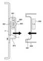
도 28b는 본 발명의 다양한 실시예에 따른 레이어드 액세서리 케이스가 거치 몸체에 결합 전 상태를 나타내는 단면도로서, 도 28a의 라인 H-H'를 따라 절개한 거치 돌출의 단면과 거치 몸체 간의 결합 상태 전을 나타내는 도면이다.
도 28c는 본 발명의 다양한 실시예에 따른 레이어드 액세서리 케이스가 거치 몸체에 결합 후 상태를 나타내는 단면도로서, 도 28a의 라인 H-H'를 따라 절개한 거치 돌출의 단면과 거치 몸체 간의 결합 상태 후를 나타내는 도면이다.
도 29a는 본 발명의 다양한 실시예에 따른 레이어드 액세사리 케이스를 나타내는 정면도이다.
도 29b는 본 발명의 다양한 실시예에 따른 레이어드 액세서리 케이스가 거치 몸체에 결합 전 상태를 나타내는 단면도로서, 도 29a의 라인 I-I'를 따라 절개한 거치 돌출의 단면과 거치 몸체 간의 결합 상태 전을 나타내는 도면이다.
도 29c는 본 발명의 다양한 실시예에 따른 레이어드 액세서리 케이스가 거치 몸체에 결합 후 상태를 나타내는 단면도로서, 도 29a의 라인 I-I'를 따라 절개한 거치 돌출의 단면과 거치 몸체 간의 결합 상태 후를 나타내는 도면이다.
도 30a는 본 발명의 다양한 실시예에 따른 케이스가 거치 몸체에 결합되기 전 상태를 나타내는 정면도이다.
도 30b는 본 발명의 다양한 실시예에 따른 거치 몸체의 평탄 부분의 다양한 실시예들을 나타내는 예시도이다.
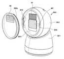
도 31a는 본 발명의 다양한 실시예에 따른 거치대의 전방을 나타내는 사시도이다.
도 31b는 본 발명의 다양한 실시예에 따른 거치대의 후방을 나타내는 사시도이다.
도 32a는 본 발명의 다양한 실시예에 따른 거치대의 후방을 나타내는 사시도이다.
도 32b는 본 발명의 다양한 실시예에 따른 거치대의 전방을 나타내는 사시도이다.
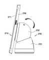
도 32c는 본 발명의 다양한 실시예에 따른 거치대의 측면을 나타내는 측면도이다.
도 32d는 본 발명의 다양한 실시예에 따른 거치대를 나타내는 분리 사시도이다.
도 33a는 본 발명의 다양한 실시예에 따른 거치대를 나타내는 정면도이다.
도 33b는 본 발명의 다양한 실시예에 따른 거치대에 전자 장치를 거치하기 전 및 거치한 후 상태를 나타내는 측면 투시도이다.1A is a perspective view illustrating a front surface of an electronic device according to various embodiments of the present disclosure;
1B is a perspective view illustrating a rear surface of an electronic device according to various embodiments of the present disclosure;
Figure 2a is a perspective view showing a layered accessory case according to various embodiments of the present invention.
Figure 2b is a rear view showing a layered accessory case according to various embodiments of the present invention.
Figure 2c is a front view showing a layered accessory case according to various embodiments of the present invention.
3A is a perspective view illustrating a layered accessory case according to various embodiments of the present disclosure;
Figure 3b is a rear view showing a layered accessory case according to various embodiments of the present invention.
Figure 3c is a front view showing a layered accessory case according to various embodiments of the present invention.
3D to 3I are rear views each showing a layered accessory case according to various embodiments of the present invention.
Figure 4a is a front view showing a layered accessory case according to various embodiments of the present invention.
Figure 4b is a front view showing a state in which the communication module is coupled to the layered accessory case according to various embodiments of the present invention.
4C is a side view illustrating a state in which a communication module is coupled to a layered accessory case according to various embodiments of the present disclosure;
4D and 4E are front views each showing a front (a) and a side (b) of a layered accessory case according to various embodiments of the present invention.
5A is a view showing a state before (a) and after (b) movement of the front surface of the layered accessory case according to various embodiments of the present invention.
Figure 5b is a cross-sectional view showing a state before the movement of the sliding key of the layered accessory case according to various embodiments of the present invention, a cross-sectional view taken along the line A-A' of Figure 5a (a).
5C is a cross-sectional view illustrating a state after movement of the sliding key of the layered accessory case according to various embodiments of the present invention, and is a cross-sectional view taken along the line B-B' of FIG. 5A (b).
6A is a view showing a state before (a) and after (b) movement of the front of the layered accessory case according to various embodiments of the present invention.
Figure 6b is a cross-sectional view showing a state before the movement of the sliding key of the layered accessory case according to various embodiments of the present invention, a cross-sectional view taken along the line C-C' of Figure 6a (a).
6C is a cross-sectional view illustrating a state after movement of the sliding key of the layered accessory case according to various embodiments of the present invention, and is a cross-sectional view taken along the line D-D' of FIG. 6A (b).
7A is a view showing a state before (a) and after (b) movement of the front of the layered accessory case according to various embodiments of the present invention.
Figure 7b is a cross-sectional view showing a state before moving the sliding key of the layered accessory case according to various embodiments of the present invention, a cross-sectional view taken along the line E-E' of Figure 7a (a).
7c is a cross-sectional view showing a state after movement of the sliding key of the layered accessory case according to various embodiments of the present invention, a cross-sectional view taken along the line F-F' of FIG. 7a (b).
7D is a cross-sectional view illustrating a state after movement of the sliding key of the layered accessory case according to various embodiments of the present invention, and is a cross-sectional view taken along the line G-G' of FIG. 7A (b).
8A is a view showing a front view (a) and a side cross-sectional view (b) of a layered accessory case according to various embodiments of the present invention, respectively, the side view (b) is along the line H-H' of the front view (a); This is a cross-sectional side view.
8B is a view showing a state before movement of the seesaw key of the layered accessory case according to various embodiments of the present invention.
Figure 8c is a view showing a state after the movement of the seesaw key of the layered accessory case according to various embodiments of the present invention.
Figure 9a is a view showing the front (a) and side (b) state before the movement of the rotary lever of the layered accessory case according to various embodiments of the present invention.
Figure 9b is a view showing the front (a) and side (b) state after the movement of the rotary lever of the layered accessory case according to various embodiments of the present invention.
9c is a perspective view illustrating a rotation mechanism configured in a layered accessory case according to various embodiments of the present disclosure;
9d to 9f are perspective views each showing the state before, during, and after the movement of the rotation lever of the layered accessory case according to various embodiments of the present invention.
10A is a view illustrating a state before movement of a connection lever provided in a layered accessory case according to various embodiments of the present disclosure;
10B is a view showing a state after movement of the connection lever provided in the layered accessory case according to various embodiments of the present invention.
10c is a cross-sectional view showing a state before movement of the connection lever provided in the layered accessory case according to various embodiments of the present invention.
10D is a cross-sectional view illustrating a state after movement of a connection lever provided in a layered accessory case according to various embodiments of the present disclosure.
11A is a view illustrating a state before extension of an extension part provided in a layered accessory case according to various embodiments of the present disclosure;
11B is a view showing a state after the extension of the extension provided in the layered accessory case according to various embodiments of the present invention.
11C is an enlarged view of a state (a) and a cross-section (b) of an extension provided in a layered accessory case before extension according to various embodiments of the present invention.
11D is an enlarged view illustrating a state (a) and a cross-section (b) of the extended part provided in the layered accessory case according to various embodiments of the present invention after extension.
12A is a view illustrating a state before rotation of a rotary lever provided in a layered accessory case according to various embodiments of the present disclosure;
12B is a view showing a state after rotation of the rotary lever provided in the layered accessory case according to various embodiments of the present invention.
12C is an enlarged view illustrating a state before rotation of a rotary lever provided in a layered accessory case according to various embodiments of the present disclosure;
12D is an enlarged view showing a state after rotation of the rotary lever provided in the layered accessory case according to various embodiments of the present invention.
13A is a view showing a state before rotation of the rotation mechanism provided in the layered accessory case according to various embodiments of the present invention.
13B is a view showing a state after rotation of the rotation mechanism provided in the layered accessory case according to various embodiments of the present invention.
13C is an enlarged view of a state (a) and a cross-section (b) of a rotation mechanism provided in a layered accessory case according to various embodiments of the present invention before rotation.
13D is an enlarged view showing a state (a) and a cross-section (b) after rotation of the rotation mechanism provided in the layered accessory case according to various embodiments of the present invention.
14A is a view illustrating a state before movement of a flexible material part provided in a layered accessory case according to various embodiments of the present disclosure;
14B is a view illustrating a state after movement of the flexible material part provided in the layered accessory case according to various embodiments of the present invention.
14C is an enlarged view showing a state before movement of the flexible material part provided in the layered accessory case according to various embodiments of the present invention.
14D is an enlarged view showing the state after rotation of the flexible material part provided in the layered accessory case according to various embodiments of the present invention.
15A is a view illustrating a state before rotation of a rotary lever provided in a layered accessory case according to various embodiments of the present disclosure;
15B is a view showing a state after rotation of the rotary lever provided in the layered accessory case according to various embodiments of the present invention.
16A is a view illustrating a state before rotation of a connection lever provided in a layered accessory case according to various embodiments of the present disclosure;
Figure 16b is a view showing a state after rotation of the connection lever provided in the layered accessory case according to various embodiments of the present invention.
17A is a view illustrating a state before rotation of a connection lever provided in a layered accessory case according to various embodiments of the present disclosure;
Figure 17b is a view showing a state after rotation of the connection lever provided in the layered accessory case according to various embodiments of the present invention.
18A is a view illustrating a state before rotation of a connection lever provided in a layered accessory case according to various embodiments of the present disclosure;
18B is a view showing a state after rotation of the connection lever provided in the layered accessory case according to various embodiments of the present invention.
19A is a view showing a front (a) and a side cross-section (b) of a sliding key of a layered accessory case before movement according to various embodiments of the present invention.
Figure 19b is a view showing the front (a) and side cross-section (b) of the state after the movement of the sliding key of the layered accessory case according to various embodiments of the present invention.
19c is an exemplary view illustrating a state in which the magnetic switch is turned off before the sliding key of the layered accessory case moves according to various embodiments of the present disclosure;
19D is an exemplary view illustrating a state in which the magnetic switch is turned on in a state after movement of the sliding key of the layered accessory case according to various embodiments of the present disclosure;
20A is a view showing a front (a) and a side cross-section (b) of a sliding key of a layered accessory case before movement according to various embodiments of the present invention.
Figure 20b is a view showing the front (a) and side cross-section (b) of the state after the movement of the sliding key of the layered accessory case according to various embodiments of the present invention.
20C is a view illustrating an on or off state of a switching device according to movement of a sliding key of a layered accessory case according to various embodiments of the present disclosure;
21A is a view illustrating an unfolded state of a foldable member provided in a layered accessory case according to various embodiments of the present disclosure;
21B is a view illustrating a folded state of a foldable member provided in a layered accessory case according to various embodiments of the present disclosure;
21c is a side view illustrating the operation of the foldable member provided in the layered accessory case according to various embodiments of the present disclosure in stages.
22A is a view illustrating an unfolded state of a foldable member provided in a layered accessory case according to various embodiments of the present disclosure;
22B is a view illustrating a folded state of a foldable member provided in a layered accessory case according to various embodiments of the present disclosure;
Figure 23a is a front view showing the appearance of the rotating wheel mounted state provided in the layered accessory case according to various embodiments of the present invention.
Figure 23b is a view showing a state after rotation of the rotary wheel provided in the layered accessory case according to various embodiments of the present invention.
23c is a view showing a state before rotation of the rotating wheel provided in the layered accessory case according to various embodiments of the present invention.
24A is a view illustrating a state before clicking a button provided in a layered accessory case according to various embodiments of the present disclosure;
24B is a diagram illustrating a state after clicking a button provided in a layered accessory case according to various embodiments of the present disclosure.
Figure 24c is a side view showing the operation of each of the buttons provided in the layered accessory case according to various embodiments of the present invention in stages.
25A is a view showing a front (a) and a side cross-section (b) of a sliding key of a layered accessory case before movement according to various embodiments of the present invention.
Figure 25b is a view showing the front (a) and side cross-section (b) of the state after the movement of the sliding key of the layered accessory case according to various embodiments of the present invention.
26A and 26B are perspective views each showing a state before being mounted on a cradle according to various embodiments of the present invention.
26C is a view showing a state in which the protrusion mounting part and the flat part are viewed from the front, respectively, according to various embodiments of the present invention.
26D is a perspective view illustrating a state before the mounting protrusion is coupled to the flat portion of the mounting body according to various embodiments of the present disclosure;
27A is a front view illustrating a state in which a case to which an electronic device is coupled according to various embodiments of the present disclosure is vertically mounted on a mounting body;
27B is a side view illustrating a state in which a case to which an electronic device is coupled according to various embodiments of the present disclosure is vertically mounted on a mounting body;
27C is a front view illustrating a state in which a case to which an electronic device is coupled according to various embodiments of the present disclosure is horizontally mounted on a mounting body;
27D is a side view illustrating a state in which a case to which an electronic device is coupled according to various embodiments of the present disclosure is horizontally mounted on a mounting body;
Figure 28a is a front view showing a layered accessory case according to various embodiments of the present invention.
28b is a cross-sectional view showing a state before coupling to the mounting body of the layered accessory case according to various embodiments of the present invention, before the coupling state between the mounting body and the cross-section of the mounting protrusion cut along the line H-H' of FIG. 28a It is a drawing showing
28c is a cross-sectional view showing a state after the layered accessory case is coupled to the mounting body according to various embodiments of the present invention, after the coupling state between the mounting body and the cross-section of the mounting protrusion cut along the line H-H' of FIG. 28a It is a drawing showing
29A is a front view illustrating a layered accessory case according to various embodiments of the present disclosure;
29b is a cross-sectional view showing the state before coupling to the mounting body of the layered accessory case according to various embodiments of the present invention, before the coupling state between the mounting body and the cross-section of the mounting protrusion cut along the line I-I' of FIG. 29a It is a drawing showing
29c is a cross-sectional view showing a state after the layered accessory case is coupled to the mounting body according to various embodiments of the present invention, after the coupling state between the mounting body and the cross-section of the mounting protrusion cut along the line I-I' of FIG. 29a It is a drawing showing
30A is a front view showing a state before the case according to various embodiments of the present invention is coupled to the mounting body.
Figure 30b is an exemplary view showing various embodiments of the flat portion of the mounting body according to various embodiments of the present invention.
Figure 31a is a perspective view showing the front of the holder according to various embodiments of the present invention.
Figure 31b is a perspective view showing the rear of the cradle according to various embodiments of the present invention.
32A is a perspective view illustrating the rear of the cradle according to various embodiments of the present disclosure;
32B is a perspective view showing the front of the cradle according to various embodiments of the present invention.
32C is a side view illustrating a side of a cradle according to various embodiments of the present disclosure;
32D is an exploded perspective view illustrating a cradle according to various embodiments of the present disclosure;
33A is a front view illustrating a cradle according to various embodiments of the present disclosure;
33B is a side perspective view illustrating a state before and after the electronic device is mounted on a cradle according to various embodiments of the present disclosure;
이하, 본 개시의 다양한 실시예가 첨부된 도면을 참조하여 기재된다. 그러나, 이는 본 개시를 특정한 실시 형태에 대해 한정하려는 것이 아니며, 본 개시의 실시예의 다양한 변경(modification), 균등물(equivalent), 및/또는 대체물(alternative)을 포함하는 것으로 이해되어야 한다. 도면의 설명과 관련하여, 유사한 구성요소에 대해서는 유사한 참조 부호가 사용될 수 있다.Hereinafter, various embodiments of the present disclosure are described with reference to the accompanying drawings. However, this is not intended to limit the present disclosure to specific embodiments, and it should be understood that various modifications, equivalents, and/or alternatives of the embodiments of the present disclosure are included. In connection with the description of the drawings, like reference numerals may be used for like components.
본 문서에서, "가진다," "가질 수 있다,”"포함한다," 또는 “포함할 수 있다” 등의 표현은 해당 특징(예:수치, 기능, 동작, 또는 부품 등의 구성요소)의 존재를 가리키며, 추가적인 특징의 존재를 배제하지 않는다.In this document, expressions such as “have,” “may have,” “include,” or “may include” are the presence of a corresponding characteristic (eg, a numerical value, function, operation, or component such as a part). and does not exclude the presence of additional features.
본 문서에서, “A 또는 B,”“A 또는/및 B 중 적어도 하나,”또는 "A 또는/및 B 중 하나 또는 그 이상" 등의 표현은 함께 나열된 항목들의 모든 가능한 조합을 포함할 수 있다. 예를 들면, “A 또는 B,“ A 및 B 중 적어도 하나,”또는 “ A 또는 B 중 적어도 하나”는, (1) 적어도 하나의 A를 포함, (2) 적어도 하나의 B를 포함, 또는 (3) 적어도 하나의 A 및 적어도 하나의 B 모두를 포함하는 경우를 모두 지칭할 수 있다.In this document, expressions such as “A or B,” “at least one of A or/and B,” or “one or more of A or/and B” may include all possible combinations of the items listed together. . For example, “A or B, “at least one of A and B,” or “at least one of A or B” means (1) includes at least one A, (2) includes at least one B, or (3) It may refer to all cases including both at least one A and at least one B.
다양한 실시예에서 사용된 “제 1,”“제 2,”“첫째,”또는“둘째,”등의 표현들은 다양한 구성요소들을, 순서 및/또는 중요도에 상관없이 수식할 수 있고, 해당 구성요소들을 한정하지 않는다. 상기 표현들은 한 구성요소를 다른 구성요소와 구분하기 위해 사용될 수 있다. 예를 들면, 제1사용자 기기와 제2사용자 기기는, 순서 또는 중요도와 무관하게, 서로 다른 사용자 기기를 나타낼 수 있다. 예를 들면, 본 개시의 권리 범위를 벗어나지 않으면서 제 1 구성요소는 제 2 구성요소로 명명될 수 있고, 유사하게 제 2 구성요소도 제 1 구성요소로 바꾸어 명명될 수 있다.Expressions such as “first,” “second,” “first,” or “second,” used in various embodiments may modify various components regardless of order and/or importance, and the corresponding components do not limit them The above expressions may be used to distinguish one component from another. For example, the first user equipment and the second user equipment may represent different user equipment regardless of order or importance. For example, without departing from the scope of the present disclosure, a first component may be referred to as a second component, and similarly, the second component may also be renamed as a first component.
어떤 구성요소(예: 제 1 구성요소)가 다른 구성요소(예: 제 2 구성요소)에 "(기능적으로 또는 통신적으로) 연결되어 ((operatively or communicatively) coupled with/to)" 있다거나, "접속되어 (connected to)" 있다고 언급된 때에는, 상기 어떤 구성요소가 상기 다른 구성요소에 직접적으로 연결되거나, 다른 구성요소(예:제 3 구성요소)를 통하여 연결될 수 있다고 이해되어야 할 것이다. 반면에, 어떤 구성요소 (예: 제 1 구성요소)가 다른 구성요소 (예: 제 2 구성요소)에 "직접 연결되어" 있다거나 "직접 접속되어" 있다고 언급된 때에는, 상기 어떤 구성요소와 상기 다른 구성요소 사이에 다른 구성요소(예: 제 3 구성요소)가 존재하지 않는 것으로 이해될 수 있다.that one component (eg, a first component) is "coupled with/to (operatively or communicatively)" to another component (eg, a second component); When referring to "connected to", it should be understood that the certain element may be directly connected to the other element or may be connected through another element (eg, a third element). On the other hand, when it is said that a component (eg, a first component) is "directly connected" or "directly connected" to another component (eg, a second component), the component and the It may be understood that other components (eg, a third component) do not exist between other components.
본 문서에서 사용된 표현 "~하도록 구성된 (또는 설정된)(configured to)"은 상황에 따라, 예를 들면, "~에 적합한 (suitable for)," "하는 능력을 가지는 (having the capacity to)," "하도록 설계된 (designed to)," "하도록 변경된 (adapted to)," "~하도록 만들어진 (made to)," 또는 "~를 할 수 있는(capable of)"과 바꾸어 사용될 수 있다. 용어 "~하도록 구성 (또는 설정)된"은 하드웨어적으로 "특별히 설계된(specifically designed to) 것만 반드시 의미하지 않을 수 있다. 대신, 어떤 상황에서는, "~하도록 구성된 장치" 라는 표현은, 그 장치가 다른 장치 또는 부품들과 함께 "~할 수 있는"것을 의미할 수 있다. 예를 들면, 문구 A, B, 및 C를 수행하도록 구성(또는 설정)된 프로세서"는 해당 동작을 수행하기 위한 전용 프로세서(예: 임베디드 프로세서), 또는 메모리 장치에 저장된 하나 이상의 소프트웨어 프로그램들을 실행함으로써, 해당 동작들을 수행할 수 있는 범용 프로세서(generic-purpose processor)(예: CPU 또는 application processor)를 의미할 수 있다.The expression "configured to (or configured to)" as used in this document, depending on the context, for example, "suitable for," "having the capacity to; It can be used interchangeably with “designed to,” “adapted to,” “made to,” or “capable of.” The term "configured (or configured to)" may not necessarily mean only "specifically designed to" in hardware. Instead, in some circumstances, the expression "a device configured to" means that the device is may mean “capable of” in conjunction with other devices or parts. For example, “a processor configured (or configured to perform) the phrases A, B, and C” means a dedicated processor for performing that operation. (eg, embedded processor) or a generic-purpose processor (eg, CPU or application processor) capable of performing corresponding operations by executing one or more software programs stored in the memory device.
본 문서에서 사용된 용어들은 단지 특정한 실시예를 설명하기 위해 사용된 것으로, 다른 실시예의 범위를 한정하려는 의도가 아닐 수 있다. 단수의 표현은 문맥상 명백하게 다르게 뜻하지 않는 한, 복수의 표현을 포함할 수 있다. 기술적이거나 과학적인 용어를 포함해서 여기서 사용되는 모든 용어들은 본 개시의 기술 분야에서 통상의 지식을 가진 자에 의해 일반적으로 이해되는 것과 동일한 의미를 가질 수 있다. 일반적으로 사용되는 사전에 정의된 용어들은 관련 기술의 문맥 상 가지는 의미와 동일 또는 유사한 의미를 가지는 것으로 해석될 수 있으며, 본 문서에서 명백하게 정의되지 않는 한, 이상적이거나 과도하게 형식적인 의미로 해석되지 않는다. 경우에 따라서, 본 문서에서 정의된 용어일지라도 본 개시의 실시예들을 배제하도록 해석될 수 없다.Terms used in this document are only used to describe specific embodiments, and may not be intended to limit the scope of other embodiments. The singular expression may include the plural expression unless the context clearly dictates otherwise. All terms used herein, including technical or scientific terms, may have the same meaning as commonly understood by one of ordinary skill in the art of the present disclosure. Terms defined in general used in the dictionary may be interpreted as having the same or similar meaning as the meaning in the context of the related art, and unless explicitly defined in this document, are not interpreted in an ideal or excessively formal meaning . In some cases, even terms defined in this document cannot be construed to exclude embodiments of the present disclosure.
본 개시의 다양한 실시예들에 따른 전자 장치는, 예를 들면, 전자 장치는 스마트폰(smartphone), 태블릿 PC(tablet personal computer), 이동 전화기(mobile phone), 화상 전화기, 전자북 리더기(e-book reader), 데스크탑 PC(desktop personal computer), 랩탑 PC(laptop personal computer), 넷북 컴퓨터(netbook computer), 워크스테이션(workstation), 서버, PDA(personal digital assistant), PMP(portable multimedia player), MP3 플레이어, 모바일 의료기기, 카메라(camera), 또는 웨어러블 장치(wearable device)(예: 스마트 안경, 머리 착용형 장치(head-mounted-device(HMD)), 전자 의복, 전자 팔찌, 전자 목걸이, 전자 앱세서리(appcessory), 전자 문신, 스마트 미러, 또는 스마트 와치(smart watch))중 적어도 하나를 포함할 수 있다.The electronic device according to various embodiments of the present disclosure may include, for example, a smartphone, a tablet personal computer (PC), a mobile phone, a video phone, and an e-book reader (e-). book reader), desktop PC (desktop personal computer), laptop PC (laptop personal computer), netbook computer (workstation), server, PDA (personal digital assistant), PMP (portable multimedia player), MP3 Players, mobile medical devices, cameras, or wearable devices (e.g. smart glasses, head-mounted-device (HMD)), electronic garments, electronic bracelets, electronic necklaces, electronic apps accessory, electronic tattoo, smart mirror, or smart watch).
어떤 실시예들에서, 전자 장치는 스마트 가전 제품(smart home appliance)일 수 있다. 스마트 가전 제품은, 예를 들면, 텔레비전, DVD(digital video disk) 플레이어, 오디오, 냉장고, 에어컨, 청소기, 오븐, 전자레인지, 세탁기, 공기 청정기, 셋톱 박스(set-top box), 홈 오토매이션 컨트롤 패널(home automation control panel), 보안 컨트롤 패널(security control panel), TV 박스(예: 삼성 HomeSync™, 애플TVTM 또는 구글 TVTM, 게임 콘솔 (예:Xbox™, PlayStation™), 전자 사전, 전자 키, 캠코더(camcorder), 또는 전자 액자 중 적어도 하나를 포함할 수 있다.In some embodiments, the electronic device may be a smart home appliance. Smart home appliances, for example, televisions, digital video disk (DVD) players, audio, refrigerators, air conditioners, vacuum cleaners, ovens, microwave ovens, washing machines, air purifiers, set-top boxes (set-top box), home automation Home automation control panel, security control panel, TV box (e.g. Samsung HomeSync™, Apple TV™ or Google TV™, game console (e.g. Xbox™, PlayStation™), electronic dictionary, electronic key , a camcorder, and may include at least one of an electronic picture frame.
다른 실시예에서, 전자 장치는, 각종 의료기기(예:각종 휴대용 의료측정기기 (혈당 측정기, 심박 측정기, 혈압 측정기, 또는 체온 측정기 등), MRA(magnetic resonance angiography), MRI(magnetic resonance imaging), CT(computed tomography), 촬영기, 또는 초음파기 등), 네비게이션(navigation) 장치, GPS 수신기(global positioning system receiver), EDR(event data recorder), FDR(flight data recorder), 자동차 인포테인먼트(infotainment) 장치, 선박용 전자 장비(예: 선박용 항법 장치, 자이로 콤파스 등), 항공 전자기기(avionics), 보안 기기, 차량용 헤드 유닛(head unit), 산업용 또는 가정용 로봇, 금융 기관의 ATM(automatic teller's machine), 상점의 POS(point of sales), 또는 사물 인터넷 장치 (internet of things)(예:전구, 각종 센서, 전기 또는 가스 미터기, 스프링클러 장치, 화재경보기, 온도조절기(thermostat), 가로등, 토스터(toaster), 운동기구, 온수탱크, 히터, 보일러 등) 중 적어도 하나를 포함할 수 있다.In another embodiment, the electronic device may include various medical devices (eg, various portable medical measuring devices (eg, a blood glucose monitor, a heart rate monitor, a blood pressure monitor, or a body temperature monitor), magnetic resonance angiography (MRA), magnetic resonance imaging (MRI), CT (computed tomography), imager, or ultrasound machine, etc.), navigation device, global positioning system receiver, EDR (event data recorder), FDR (flight data recorder), automotive infotainment device, marine use Electronic equipment (e.g. navigation devices for ships, gyro compasses, etc.), avionics, security devices, head units for vehicles, industrial or domestic robots, automatic teller's machines (ATMs) in financial institutions, POS in stores (point of sales), or internet of things (e.g. light bulbs, sensors, electricity or gas meters, sprinkler devices, smoke alarms, thermostats, street lights, toasters, exercise equipment, It may include at least one of a hot water tank, a heater, a boiler, etc.).
어떤 실시예에 따르면, 전자 장치는 가구(furniture) 또는 건물/구조물의 일부, 전자 보드(electronic board), 전자 사인 수신 장치(electronic signature receiving device), 프로젝터(projector), 또는 각종 계측 기기(예:수도, 전기, 가스, 또는 전파 계측 기기 등) 중 적어도 하나를 포함할 수 있다. 다양한 실시예에서, 전자 장치는 전술한 다양한 장치들 중 하나 또는 그 이상의 조합일 수 있다. 어떤 실시예에 따른 전자 장치는 플렉서블 전자 장치일 수 있다. 또한, 본 개시의 실시예에 따른 전자 장치는 전술한 기기들에 한정되지 않으며, 기술 발전에 따른 새로운 전자 장치를 포함할 수 있다.According to some embodiments, the electronic device is a piece of furniture or a building/structure, an electronic board, an electronic signature receiving device, a projector, or various measuring instruments (eg, water, electricity, gas, or a radio wave measuring device). In various embodiments, the electronic device may be a combination of one or more of the various devices described above. The electronic device according to an embodiment may be a flexible electronic device. In addition, the electronic device according to an embodiment of the present disclosure is not limited to the above-described devices, and may include a new electronic device according to technological development.
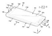
도 1a는 본 발명의 다양한 실시예들에 따른 전자 장치의 전면을 나타내는사시도이다. 도1b는 본 발명의 다양한 실시예들에 따른 전자 장치의 후면을 나타내는 사시도이다.직교좌표계가 사용되는데, X축 방향은 전자 장치의 가로 방향을 의미하고, Y축은 전자 장치의 세로 방향을 의미하며, Z축은 전자 장치의 두께 방향을 의미할 수 있다.1A is a perspective view illustrating a front surface of an electronic device according to various embodiments of the present disclosure; 1B is a perspective view illustrating a rear surface of an electronic device according to various embodiments of the present disclosure. A Cartesian coordinate system is used, wherein the X-axis direction means a horizontal direction of the electronic device, and the Y-axis means a vertical direction of the electronic device, , Z axis may mean a thickness direction of the electronic device.
도 1a, 도 1b를참조하면, 다양한실시예에따른전자장치(100)는외관을 담당하고, 전자 부품을 보호하기 위한 하우징(110)을 포함할 수 있다. 다양한 실시예에 따른 하우징(110)은 제1방향(①)으로 향하는 제1면과, 상기 제1방향(①)과 반대인 제2방향(②)으로 향하는 제2면과, 상기 각각의 제1,2방향(①,②)과 수직인 측방향으로 향하며, 상기 제1,2면 사이의 공간을 적어도 일부 감싸는 측면을 포함할 수 있다.측방향은 제3방향(③)이거나, 제4방향(④)이거나, 제3,4방향(③,④)을 모두 포함할 수 있다.하우징(110)의 제1면은 제1플레이트이고, 하우징(110)의 제2면은 제2플레이트로 구성될 수 있다.Referring to FIGS. 1A and 1B , an
다양한 실시예에 따른 하우징(110)은 제1방향(①)이 상방으로 향하면, 제1면은 하우징의 상면일 수 있고, 제2방향(②)이 하방으로 향하면, 제2면은 하우징의 후면일 수 있다. 예컨대, 하우징(110)은 제1방향(①)이 상방으로 향하면, 제1면이 전면일 수 있고, 제2방향(②)이 하방으로 향하면, 제2면이 후면일 수 있다.As for the
다양한 실시예에 따른 하우징(110)은 복수 개의 측면을 포함할 수 있다. 예컨대, 측면은 하우징(110)의 상부 엣지(110a)에 있는 측면이나, 하우징의 하부 엣지(110b)에 있는 측면이나, 하우징의 좌측 엣지(110c)에 있는 측면이나, 하우징의 우측 엣지(110d)에 있는 측면을 포함할 수 있다. 상부 엣지(110a), 하부 엣지(110b), 좌측 엣지(110c) 및 우측 엣지(110d)는 합해서 전자 장치(100)의 테두리나 둘레를 구성할 수 있다.The
다양한 실시예에 따른 전자 장치(100)는 하나의 디스플레이(101)를 포함할 수 있다. 다양한 실시예에 따른 하나의 디스플레이(101)는 평탄형 디스플레이(101a)(flat display)와, 평탄형 디스플레이(101a)의 적어도 하나 이상의 엣지 영역에 배치된 곡형 디스플레이(curved display)(101b,101c)를 포함할 수 있다. 예컨대, 디스플레이(101)는 하우징(110)의 적어도 50% 이상의 면적을 차지할 수 있다. 다양한 실시예에 따른 디스플레이(101)는 디스플레이 모듈과 투명 부재(예컨대 글래스 커버 또는 투명 윈도우)를 포함할 수 있다. 디스플레이 모듈은 디스플레이 패널 및 터치 패널을 포함할 수 있다. 평탄형 디스플레이(101a)와 곡형 디스플레이(101b,101c)는 하나의 플렉시블 타입의 디스플레이 모듈에 의해 구성될 수 있다.The
다향한 실시예에 따른 평탄형 디스플레이(101)는 둘레 부분, 즉 좌우 엣지에 제1,2곡형 디스플레이(101b,101c)가 배치될 수 있다. 본 실시예에서는 제1,2곡형 디스플레이(101b,101c)가 평탄형 디스플레이(101)의 좌우 엣지에 배치되는 것으로 예시하였지만, 곡형 디스플레이는 상기 위치에 제한되지 않으며, 다양한 엣지 영역에 배치될 수 있다.In the
예컨대, 곡형 디스플레이는 하우징(110)의 상부 엣지(110a)나, 하부 엣지(110b)나, 좌측 엣지(110c)나, 우측 엣지(110d)나, 상하 엣지(110a,110b), 좌우 엣지(110c,110d), 상하좌우 엣지(110a,110b,110c,110d) 중 어느 하나의 위치에 배치될 수 있다. 제1,2곡형 디스플레이(122,123)가 배치되지 않은 상하 엣지(110a,110b)는 금속 재질의 하우징의 일부분을 포함할 수 있다. 예컨대, 금속 재질의 하우징 일부분은 외부 금속 프레임으로서, 절연체로 구분되어서, 안테나 방사체로 동작할 수 있다.For example, the curved display has the
다양한 실시예에 따른 전자 장치(100)는 상대방의 음성을 출력하기 위하여 배치되는 리시버(102)를 포함할 수 있다. 다양한 실시예에 따른 전자 장치(100)는 상대방에게 사용자의 음성을 송신하기 위하여 배치되는 마이크로폰 장치(103)를 포함할 수 있다.The
다양한 실시예에 따른 전자 장치(100)는 리시버(102)가 설치되는 주변에 전자 장치(100)의 다양한 기능을 수행하기 위한 부품(component)들이 배치될 수 있다. 부품들은 적어도 하나의 센서 모듈(104)을 포함할 수 있다. 이러한 센서 모듈(104)은, 예컨대, 조도 센서(예: 광센서), 근접 센서(예: 광센서), 적외선 센서, 초음파 센서, 지문 인식 센서 또는 홍채 인식 센서 중 적어도 하나의 센서를 포함할 수 있다. 다양한 실시예에 따른 부품은 전면 카메라 장치(105)를 포함할 수 있다. 다양한 실시예에 따르면, 부품은 전자 장치의 상태 정보를 사용자에게 인지시켜주기 위한 인디케이터(106)(예: LED 장치)를 포함할 수 있다.In the
다양한 실시예에 따른 전자 장치(100)는 마이크로폰 장치(103)의 일측으로 배치되는 스피커 장치(108)를 포함할 수 있다. 마이크로폰 장치(103)의 타측으로 배치되며, 외부 장치에 의한 데이터 송수신 기능 및 외부 전원을 인가받아 전자 장치(100)를 충전시키기 위한 인터페이스 컨넥터 포트(107)를 포함할 수 있다. 다양한 실시예에 따른 전자 장치(100)는 인터페이스 컨넥터 포트(107)의 일측에 배치되는 이어잭 홀(109)을 포함할 수 있다.The
다양한 실시예에 따른 전자 장치(100)는 하우징(110)을 포함할 수 있다. 다양한 실시예에 따른 하우징(110)은 도전성 부재 및 비도전성 부재로 형성될 수 있다. 하우징(110)은 전자 장치(100)의 테두리를 따라 배치되며, 전면의 일부 또는 후면의 적어도 일부 영역까지 확장되는 방식으로 배치될 수 있다. 하우징(110)은 전자 장치(100)의 테두리를 따라 전자 장치(100)의 두께의 적어도 일부를 정의하며, 폐루프(closed loop) 형상으로 형성될 수 있다. 그러나 이에 국한되지 않으며, 하우징(110)은 전자 장치(100)의 두께 중 적어도 일부에 형성될 수도 있다. 하우징(110)은 적어도 일부가 전자 장치(100)의 내부에 내장될 수도 있다.The
다양한 실시예에 따른 전자 장치(100)는 제1면과 대향되는 제2면(예:후면)에 배치되는 후면 윈도우(111)를 포함할 수 있다. 다양한 실시예에따른 전자 장치(100)는 후면 윈도우(111)를 통하여 배치되는 후면 카메라 장치(112)를 포함할 수 있다. 다양한 실시예에 따르면, 전자 장치(100)는 후면 카메라 장치(112)의 일측에 배치되는 적어도 하나의 전자 부품(113)을 포함할 수 있다. 다양한 실시예에 따르면, 전자 부품(113)은 조도 센서(예: 광 센서), 근접 센서(예: 광 센서), 적외선 센서, 초음파 센서, 심박 센서, 플래시 장치 또는 지문 인식 센서 중 적어도 하나를 포함할 수 있다.The
다양한 실시예에 따른 전자 장치(100)는 하우징(110) 내에 통신부가 배치되어서, 후술하는 제1,2통신칩과 무선 방식 또는 유선 방식으로 통신할 수 있다. 예컨대, 각각의 제1,2통신칩은 제1,2근거치 통신 모듈을 각각 포함할 수 있다.In the
이하에서는 도면들을 참조하여, 본 발명의 다양한 실시예에 따른 전자 장치를 보호하고, 보조 전자장치로 활용되며, 장식 기능을 가진, 전자 장치에서 착탈되어 교체가능한 레이어드(layered) 악세사리 케이스의 다양한 실시예들에 대해서 설명하기로 한다.Hereinafter, with reference to the drawings, various embodiments of a removable and replaceable layered accessory case from an electronic device that protects an electronic device, is used as an auxiliary electronic device, and has a decorative function according to various embodiments of the present disclosure to explain about them.
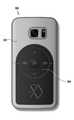
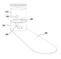
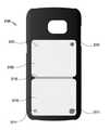
도 2a 내지 도 2c를 참조하면, 다양한 실시예에 따른 레이어드 악세사리 케이스(200)는 전자 장치(예 ; 도 1a, 도 1b의 전자 장치100)의 제2면, 예컨대 전자 장치의 후면(백 커버)에서 착탈되는 보호 케이스로서, 보조 전자 장치로서 동작할 수 있다.2A to 2C , the layered
다양한 실시예에 따른 레이어드 악세사리 케이스(200)는 외장 커버, 보호 커버, 보호 케이스, 액세사리 커버, 외장 케이스, 보조 커버, 보조 케이스 등으로 지칭할 수 있다.다양한 실시예에 따른 레이어드 액세서리 케이스(이하에서 케이스라 지칭하기로 한다)는 합성 수지(PC) 재질로 구성될 수 있고, 리지드한(rigid) 재질이나 플렉시블한(flexible) 재질로 구성될 수 있다. 또한, 케이스(200)는 전자 장치를 보호하는 형상으로 구성될 수 있고, 다양한 형상 및 색상을 구현하여 장신구로서 기능을 수행할 수 있다. 케이스(200)에는 전자 장치의 후면에 배치된 카메라 모듈을 위한 개구(201)가 형성될 수 있다.The layered
다양한 실시예에 따른 케이스(200)는 제1케이스(210)와, 제2케이스(220)로 구성될 수 있다. 제1케이스(210)는 기본 케이스로서, 전자 장치와 결합 및 보호가능한 형상으로 구성되며, 전자 장치에서 착탈될 수 있다. 제2케이스(220)는 제1케이스(210)에 일체형으로 구성되거나, 착탈가능하게 결합될 수 있는 보조 케이스일 수 있다.The
다양한 실시예에 따른 제1케이스(210)는 전자 장치의 측면 및 제2면의 적어도 일부를 감싸는 형상으로 구성될 수 있으며, 제 1 케이스(210) 일부분에 제2케이스(220)가 결합될 수 있다.The
다양한 실시예에 따른 제2케이스(220)는 제1케이스(210)에 결합되되, 제1케이스(210)와 동일한 레이어드 형태로 구성되거나, 제1케이스(210)로부터 일부 돌출된 형상으로 구성될 수 있다. 예컨대, 제2케이스(220)는 위에서 봤을 때(in top view) 원형으로 구성되어서, 제1케이스(210)에 회전가능하게 구성될 수 있다.The
다양한 실시예에 따른 제1케이스(210)는 제1통신칩(제1기능 통신부), 예컨대 근거리 무선통신 칩(NFC1)(예 ; 근거리 무선 통신 안테나)이 실장될 수 있다. 제1근거리 무선 통신 칩(NFC1)은 제1케이스(210)의 전면이나 후면에 배치될 수 있다.In the
다양한 실시예에 따른 제2케이스(220)는 제2통신칩(제2기능 통신부), 예컨대 근거리 무선 통신칩(NFC2)이 실장될 수 있다. 전자 장치는 제2통신칩을 사용하여 별도의 서비스 적용이 가능할 수 있다. 제2근거리 무선 통신 칩(NFC2)은 제2케이스(220)의 전면이나 후면에 배치될 수 있다. 또는, 제1,2케이스(210,220) 중, 어느 하나에만 근거리 무선 통신칩이 배치될 수 있다.In the
이하에서는 첨부된 도면을 참조하여 제1케이스에 결합된 제2케이스의 다양한 실시예들에 대해서 설명하기로 한다.Hereinafter, various embodiments of the second case coupled to the first case will be described with reference to the accompanying drawings.
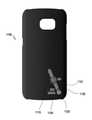
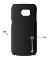
도 3a내지 도 3c를 참조하면, 다양한 실시예에 따른 케이스(300)는 도 2에 도시된 케이스(200)와 적어도 일부 또는 전부가 동일하게 구성될 수 있다. 다양한 실시예에 따른 케이스(300)는 버튼(321)이 구성된 제2케이스(320)가 제1케이스(310)에 구성될 수 있다. 제2케이스(320)에 구성된 버튼(321)의 눌러짐에 따라 케이스는 보조 전자 장치로 동작할 수 있다. 버튼(321)은 제2케이스의 외면에서 약간 돌출된 형상으로 배치될 수 있다. 이러한 버튼(321)을 이용한 자동 스위칭 구조는 후술하기로 한다. 도 28a, 도 28b에서 버튼을 이용한 자동 스위칭 구조에 대해서 상세하게 설명하기로 한다.Referring to FIGS. 3A to 3C , the
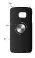
도 3d를 참조하면, 다양한 실시예에 따른 케이스(330)는 도 3a에 도시된 케이스(300)와 적어도 일부 또는 전부가 동일하게 구성될 수 있다. 다양한 실시예에 따른 케이스(330)는 핑거 링(334)이 구비된 제2케이스(332)가 제1케이스(331)에 구성될 수 있다. 제2케이스(332)에 핑거 링(334)이 구성되어서, 핑거 링(334)이 전자 장치의 그립 장치로서 활용될 수 있다. 예컨대, 핑거 링은 다양한 링 형상에 제한될 필요는 없으며, 다양한 형상으로 구성될 수 있고, 회전가능하게 구성될 수 있다.Referring to FIG. 3D , at least a part or all of the
도 3e를 참조하면, 다양한 실시예에 따른 케이스(340)는 도 3에 도시된 케이스(300)와 적어도 일부 또는 전부가 동일하게 구성될 수 있다. 다양한 실시예에 따른 케이스(340)는 적어도 일부 영역에 다이얼 버튼(344)이 형성된 제2케이스(342)가 제1케이스(341)에 구성될 수 있다. 제2케이스(342)에 형성된 다이얼 버튼(344)은 제1케이스(341)에 결합되어 데이터 입력 장치로 활용될 수 있다. 다이얼 버튼(344)은 제2케이스(342)에 원형으로 구성되어서, 시계방향 또는 반시계 방향으로 회전시킨 다음에 누름 동작으로 원하는 데이터를 입력할 수 있다. 다이얼 버튼(344)은 제2케이스(342) 일부 또는 전부에 배치될 수 있는데, 도 3e에는 다이얼 버튼(344)이 제2케이스 전부에 배치된 실시예가 예시되었다. 다이얼 버튼(344)은 제1케이스(341)의 외면과 대략적으로 동일 평면상태 또는 약간 돌출된 상태로 배치될 수 있다. 또한, 다이얼 버튼(344)은 제1케이스(341)의 일부 영역일 수 있다.Referring to FIG. 3E , at least a part or all of the
도 3f를 참조하면, 다양한 실시예에 따른 케이스(350)는 도 3에 도시된 케이스(300)와 적어도 일부가 동일하게 구성될 수 있다. 다양한 실시예에 따른 케이스(350)는 적어도 일부 영역에 터치 패드(354)가 적용된 제2케이스(352)가 제1케이스(351) 배면에 구성될 수 있다. 제2케이스(352)는 터치 패드(354)가 구성되어서, 터치 패드(354)가 배치된 제2케이스(352)는 제1케이스(351)의 일부 영역일 수 있다. 터치 패드(354)는 제1케이스(351)에 결합되어서 데이터 입력 장치로 활용될 수 있다. 터치 패드(354)는 터치 동작으로 데이터를 입력하는 터치 감음성 패널을 포함할 수 있다. 터치 패드(354)는 복수 개의 터치 키들이 배열될 수 있다.Referring to FIG. 3F , the
도 3g를 참조하면, 다양한 실시예에 따른 케이스(360)는 도 3에 도시된 케이스(300)와 적어도 일부가 동일하게 구성될 수 있다. 다양한 실시예에 따른 케이스(360)는 적어도 일부 영역에 복수 개의 키 버튼(354)가 제1케이스(351) 배면에 구성될 수 있다. 키 버튼들(364)은 제1케이스(361)의 일부 영역일 수 있다. 키 버튼들(364)은 제1케이스(361)에 결합되어서 데이터 입력 장치로 활용될 수 있다. 키 버튼들(364)는 누름 동작으로 데이터를 입력할 수 있다.Referring to FIG. 3G , the
도 3h, 도 3i를 참조하면, 다양한 실시예에 따른 케이스(370)는 도 3에 도시된 케이스와 적어도 일부가 동일하게 구성될 수 있다. 다양한 실시예에 따른 케이스(370)는 조그 다이얼(374)이 제1케이스(371)에 구성될 수 있다. 조그 다이얼(374)은 회전 동작 후에 누름 동작으로 조작할 수 있으며, 특히 차량에 놓여져서, 운전 중에 하나의 콘트롤러로서 사용될 수 있다.Referring to FIGS. 3H and 3I , the
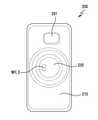
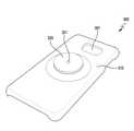
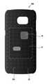
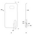
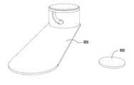
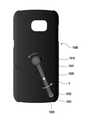
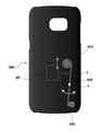
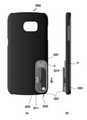
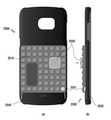
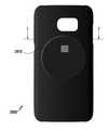
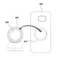
도 4a 내지 도 4c를 참조하면, 다양한 실시예에 따른 케이스(400)는 배면에 블록 장남감(예컨대 레고 등등)과 유사한 결합 구조를 가지는 돌기들(401)이 전체적으로 구성될 수 있다. 예컨대 돌기들(401)은 케이스(400) 배면에 가로 및 세로 방향으로 등간격으로 규칙적으로 배열될 수 있다. 위에서 봤을 때, 돌기들(401)은 상단이 원형 형상에 한정될 필요는 없으며, 다각형상 등으로 구성될 수 있다. 돌기들(401)은 케이스(400) 배면에 일부 또는 전체적으로 형성될 수 있는데, 두가지 영역으로 구분될 수 있다.4A to 4C , the
다양한 실시예에 따른 케이스(400) 배면은 중앙 영역(a1)과, 주변 영역(a2)으로 구분될 수 있다. 중앙 영역(a1)과 주변 영역(a2)은 위치에 의해 구분될 수 있고, 근거리 통신 모듈(M)의 결합 유무에 의해 구분될 수 있다. 이를 위해, 중앙 영역(a1)에 있는 각각의 돌기(401) 상단면은 면처리 가공을 하여, 주변 영역(a2)에 있는 각각의 돌기(401)와 다르게 구성하여, 시각적으로 구분할 수 있다.예를 들어, 케이스(400) 배면은 시각적으로 구분할 수 있을 뿐만 아니라, 촉각적으로도 구분할 수 있다. 예를 들어, 중앙 영역(a1)에 있는 각각의 돌기(401) 상면에 홈을 형성하고, 주변 영역(a2)에 있는 돌기(401)상면에는 홈을 형성하지 않음으로서, 촉각적으로 중앙 영역(a1)과 주변 영역(a2)을 구분할 수 있다.The rear surface of the
다향한 실시예에 따른 케이스(400)는 중앙 영역(a1)에 있는 각각의 돌기(401)를 주변 영역(a2)에 있는 각각의 돌기(401)와 다른 색상으로 구성하여 시각적으로 구분할 수 있다.케이스(400)의 배면의 영역 구분은 상기 실시예들에 한정될 필요는 없으며,가능한 다양한 방법을 통해 중앙 영역(a1)과 주변 영역(a2)을 구분 할 수 있다. 다양한 실시예에 따른 중앙 영역(a1)은 면처리 가공된 상단면을 가지는 돌기(401)에 결합 모듈, 예를 들어 근거리 통신 모듈(M)이 조립될 수 있는 영역일 수 있다. 케이스(400) 배면에 형성된 중앙 영역(a1)에 결합된 근거리 통신 모듈(M)은 버튼으로 동작할 수 있다. 근거리 통신 모듈(M)의 일면에도 블록 장난감과 같은 유사한 돌기 형상의 결합 구조가 구성될 수 있다. 블록 장남감의 결합 구조를 가지는 통신 모듈(M)은 중앙 영역(a1) 이내에 결합될 수 있다. 예컨대 결합 구조는 돌기와 홈으로 구성될 수 있다.The
다양한 실시예에 따른 근거리 통신 모듈은 버튼과, 근거리 통신 칩이 내장될 수 있다.A short-distance communication module according to various embodiments may have a button and a short-distance communication chip embedded therein.
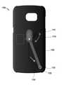
도 4d를 참조하면, 다양한 실시예에 따른 케이스(410)는 배면에 리모콘 파트(412)가 착탈가능하게 결합될 수 있다. 예컨대 리모콘 파트(412)는 4방향 키(414)와 근거리 통신 서비스 활성화 키(416)를 포함할 수 있다. 다양한 실시예에 따른 리모콘 파트(412)는 4방향 키(412)와 인접하게 근거리 통신 서비스 활성화 버튼(416)이 배치될 수 있다. 리모콘 파트(412)를 케이스(400)에서 분리하면, 리모콘 파트(412)는 독립적인 전자 장치의 리모콘으로 사용될 수 있다.Referring to FIG. 4D , the
도 4e를 참조하면, 다양한 실시예에 따른 리모콘 파트(422)는 케이스(420)에 도 4d에 도시된 리모콘 파트(412) 배치의 반대 방향으로 결합될 수 있다.Referring to FIG. 4E , the
이하에서는 전자 장치의 락 스크린 상태에서도 하나의 모션으로 근거리 통신 서비스 기능이 가능한 스위칭 구조에 대해서 설명하기로 한다. 예컨대, 다양한 실시예에 따른 케이스는 하나의 모션으로 근거리 통신을 활성화하기 위한 스위칭 구조를 더 포함할 수 있으며, 대략 동시적으로 동작하는 접촉 스위칭 구조와 자성 스위칭 구조 등을 활용할 수 있다. 언급된 하나의 모션은 예를 들어, 원 터치 동작이나, 하나의 누름 동작이나, 하나의 회전 동작이나, 하나의 결합 또는 거치 동작 또는 하나의 슬라이딩 동작들 중, 선택된 어느 하나의 동작 또는 이들 동작의 조합을 포함할 수 있다. 이하에서 하나의 모션은 상기 연결된 하나의 동작 또는 둘 이상의 조합으로 이루어진 동작들을 의미할 수 있다.Hereinafter, a switching structure in which a short-range communication service function is possible with one motion even in the lock screen state of the electronic device will be described. For example, the case according to various embodiments may further include a switching structure for activating short-range communication with one motion, and may utilize a contact switching structure and a magnetic switching structure that operate approximately simultaneously. One motion mentioned is, for example, a one-touch operation, one pressing operation, one rotation operation, one combining or holding operation, or one sliding operation, selected one operation or of these operations Combinations may be included. Hereinafter, one motion may refer to the one connected operation or operations made up of a combination of two or more.
도 5a 내지 도 5c를 참조하면, 다양한 실시예에 따른 케이스(500)는 제1방향으로 향하는 제1면(미도시)과, 제1방향과 반대방향으로 향하는 제2면을 포함할 수 있다. 케이스(500)의 제1면은 내면으로서, 전자 장치의 백 커버와 대면하는 내면이고, 제2면은 케이스(500)의 외부면일 수 있다.5A to 5C , the
다양한 실시예에 따른 케이스(500)는 제2면에 조작가능한 적어도 하나 이상의 스위칭 장치가 배치될 수 있다. 특히, 다양한 실시에에 따른 스위칭 장치는 케이스(500) 제2면에서, 손가락 동작이 편리한 영역, 예컨대 하단 영역에 스위칭 장치가 배치될 수 있다. 하지만, 스위칭 장치는 케이스(500) 하단 영역에 배치되는 것으로 한정될 필요는 없으며, 케이스(500)제2면에서 손가락 동작이 용이한 영역에 배치될 수 있다. 스위칭 장치는 케이스(500) 제2면에 레이어드 타입으로 적어도 한 개 이상 배치될 수 있다.At least one operable switching device may be disposed on the second surface of the
다양한 실시예에 따른 스위칭 장치는 슬라이드 키(510)의 좌우 이동 유무에 따라 온되거나 오프될 수 있다. 예컨대, 도 5b와 같이 좌측으로 이동된 상태에서는 스위칭 장치가 오프된 상태이고, 도 5c와 같이 우측으로 이동된 상태에서는 스위칭 장치가 온된 상태일 수 있다. 언급된 좌우 방향은 전자 장치의 가로 방향을 기준으로 좌우 방향을 의미할 수 있다.The switching device according to various embodiments may be turned on or off depending on whether the
다양한 실시예에 따른 스위칭 장치는 슬라이드 키(510)와, 접속 스위치(520)와, 자성 스위치(530)를 포함할 수 있다.The switching device according to various embodiments may include a
다양한 실시예에 따른 슬라이드 키(510)는 케이스(500) 제2면에 형성된 리세스(501)에 수용되어서, 좌우 방향으로 이동하는 슬라이딩 부재로서, 도 5a의 (a) 상태는 스위치가 오프된 상태이고, 도 5a의 (b) 상태는 스위치가 온된 상태를 나타낸다. 슬라이딩 키(510)는 제1방향으로 향하는 제1면과, 제1방향과 반대방향인 제2면을 향하는 제2면을 포함할 수 있다. 슬라이딩 키(510)의 제1면은 내면으로 숨겨지는 면으로서, 케이스(500)의 제2면과 대면할 수 있는 면이고, 슬라이딩 키(510)의 제2면은 외부에 노출되는 외면으로서, 슬라이딩 동작 시에 터치되는 면일 수 있다.The
다양한 실시예에 따른 접촉 스위치(520)는접촉 단자(521)와, 케이스 제2면에 형성된 수용 공간에 배치된 택트 스위치(522)를 포함할 수 있다.The
다양한 실시예에 따른 접촉 단자(521)는 슬라이딩 키(510)의 제2면에 구비되며, 각각의 단은 벤딩되어 슬라이딩 키(510)에 각각 고정되고, 상기 각 단의 중간 부분은 접촉(가압) 부분으로서, 택트 스위치(522) 방향으로 볼록하게 벤딩된 형상으로 구성될 수 있다. 예컨대 접촉 단자(521)는 탄성 변경이 가능한 형상으로 구성되어서, 택트 스위치(522)와의 접속 유무에 따라 형상이 변형될 수 있다. 예를 들어 접촉 단자(521)는 상하 방향으로 압축되거나 인장가능한 형상으로 구성되어서, 택트 스위치(522)와의 접속 상태를 유지할 수 있다.
다양한 실시예에 따른 택트 스위치(522)는케이스(500)의 수용공간에 배치되되, 상기 접촉 단자(521)와 인접한 곳에 배치될 수 있다. 예컨대 택트 스위치(522)의 배치 위치는 수용 공간 바닥에 배치되어서, 슬라이딩 키(521)가 좌측으로 이동되었을 때 접촉 단자(521)와 이격되고, 슬라이딩 키(510)가 우측으로 이동되었을 때 접촉 단자(521)와 접속되는 위치에 배치될 수 있다. 택트 스위치(522)는 접촉 단자(521)에 의해 눌려지는 버튼(522a), 예컨대 조작 돌기(예; 액츄에이터)가 구비될 수 있고, 조작 돌기(522a)가 눌려짐에 따라 택트 스위치(522)는 동작할 수 있다. 도 5c와 같은 상태에서, 슬라이딩 키(510)가 좌측으로 이동하면, 접촉 스위치(522)는 도 5b와 같은 상태가 될 수 있다.The
다양한 실시예에 따른 자성 스위치(530)는 접속 스위치(520)와 인접한 곳에 배치될 수 있다. 자성 스위치(530)는 마그네트(531)와, 자성 센서(532)로 구성될 수 있다. 다양한 실시예에 따른 마그네트(531)는 슬라이딩 키(510)의 제2면에서 접촉 단자(521)와 근접한 곳, 예를 들어 바로 옆에 배치될 수 있다. 마그네트(531)는 조각 형상으로, 이동 공간의 바닥면과 대면할 수 있다. 다양한 실시예에 따른 자성 센서(532)는 케이스(500) 내에 배치되되, 택트 스위치(522)와 근접한 곳에 배치될 수 있다. 슬라이딩 키(510)가 좌측에 배치된 상태에서, 마그네트(531)와 자성 센서(532)는 서로 원거리에 위치하여 자성 센서(532)는 동작하지 앉고, 슬라이딩 티(510)가 우측에 배치된 상태에서, 마그네트(531)와 자성 센서(532)는 서로 대면한 상태로 근거리에 배치되어서, 자성 센서(532)는 온되어 감지 신호를 출력할 수 있다.The
다양한 실시예에 따른 자성 스위치(530)는 접속 스위치(520)와 거의 동시적으로 동작할 수 있다. 슬라이딩 키(510)의 제2면에 접촉 단자(521)와 마그네트(531)가 제1거리로 이격되게 배치되고, 택트 스위치(522)와 자성 센서(532)가 대략적으로 제1거리로 이격되게 배치될 수 있다. 스위칭 장치를 제2면의 수직상방에서 봤을 때, 상기 택트 스위치(522)와 자성 센서(532)는 대략적으로 제1거리로 이격되게 배치될 수 있다.The
이러한 배치 관계에 따라서, 슬라이딩 키(510)를 좌측에서 우측으로 이동시키면, 접촉 스위치(520)와 자성 스위치(530)는 대략적으로 동시에 동작할 수 있다. 즉, 택트 스위치(522)와 자성 센서(532)는 대략적으로 동시적으로 신호를 전달할 수 있다.다양한 실시에에 따른 스위칭 장치는 자성 센서(532) 센싱을 통해 슬립(sleep)을 깨우고 또는 락 스크린(lock screen) 상태를 해체 할 수 있고,택트 스위치 접촉을 통해 근접 통신 서비스를 활성화 시킬 수 있다. 이러한 스위치의 구조에 따라서, 락 스크린 상태의 전자 장치에서, 위급한 상황에 슬라이딩 키(510)를 하나의 모션, 예컨대 한번 만 이동시킴으로서, 위급한 상황을 호출할 수 있다.According to this arrangement relationship, when the sliding
도 6a 내지 도 6c를 참조하면, 다양한 실시예에 따른 케이스는 도 5a 내지 도 5c에 도시된 케이스(500)와 비교하여, 그 차이점만을 설명하고, 나머지 동일한 구성에 대해서는 중복 기재를 피하기 위해 생략하기로 한다. 다양한 실시예에 따른 케이스(600)에 장착된 스위칭 장치는 전자 장치의 세로 방향을 따라서 배치될 수 있다.6A to 6C , the case according to various embodiments is compared with the
다양한 실시예에 따른 스위칭 장치는 케이스(600)의 세로 방향(X축 방향)으로 이동가능하게 배치되는 슬라이딩 키(610)와, 접속 스위치(620)와, 자성 스위치(630)를 포함할 수 있다.The switching device according to various embodiments may include a sliding key 610 that is movably disposed in the vertical direction (X-axis direction) of the
다양한 실시예에 따른 슬라이딩 키(610)는 케이스(600)의 세로 방향으로 슬라이동 이동을 하고, 슬라이딩 키(610)의 제2면과 케이스(600)의 제2면 사이에 있는 이동 공간에 수용되는 접속 스위치(620)와 자성 스위치(630)로 구성되는 스위치 장치의 구조에 대해서는 이미 도 5b, 도 5c에서 상세히 설명하였기 때문에 생략한다.Sliding key 610 according to various embodiments moves to slide in the longitudinal direction of the
도 7a 내지 도 7c를 참조하면, 다양한 실시예에 따른 케이스(700)는 도 5a 내지 도 5c에 도시된 케이스(500)와 비교하여, 그 차이점만을 설명하고, 나머지 동일한 구성에 대해서는 중복 기재를 피하기 위해 생략하기로 한다.Referring to FIGS. 7A to 7C , the
다양한 실시예에 따른 스위칭 장치는 케이스(700)의 가로 방향(Y축 방향)으로 이동가능하게 배치되는 슬라이딩 키(710)와, 접속 스위치(720)와, 자성 스위치(730)로 구성될 수 있다. 자성 스위치(730)는 마그네트(731)와 자성 센서(732)를 포함하되, 마그네트(731)는 접촉 단자(721)와 중첩되지 않게 배치되고, 자성 센서(732)는 택트 스위치(721)와 중첩되지 않게 배치될 수 있다.The switching device according to various embodiments may include a sliding key 710 that is movably disposed in a horizontal direction (Y-axis direction) of the
다양한 실시예에 따른 마그네트(731)는 슬라이딩 키(710)의 제2면에 배치되되, 접촉 단자(721)와 중첩되지 않게 배치되고, 슬라이딩 키(710)의 제2면에 접촉 단자(721)와 평행하게 배치될 수 있다. 마그네트(731)는 슬라이딩 키(710)의 제2면에 접촉 단자(721)의 세로 방향으로 향하는 곳에 배치될 수 있다.The
다양한 실시예에 따른 자성 센서(732)는 전자 장치 내부에 배치되되, 위에서 봤을 때, 택트 스위치(722)와 중첩되지 않게 배치될 수 있다.The
상기 케이스(700)의 제2면에서 슬라이딩 키(710)가 좌측에 있으면, 접촉 단자(721)와 택트 스위치(722)는 이격된 상태이고, 마그네트(731)는 자성 센서(732)와 원거리 상태라서, 접속 스위치(720)와 자성 스위치(730)는 각각 오프 상태일 수 있다. 케이스(700)의 제2면에서 슬라이딩 키(710)가 우측에 있으면, 접촉 단자(721)와 택트 스위치(722)는 접촉된 상태이고, 마그네트(731)는 자성 센서(732)와 근거리 상태, 예컨대 위에서 봤을 때 중첩된 상태라서, 접속 스위치(720)와 자성 스위치(730)는 각각 온 상태라서, 각각의 신호를 전달할 수 있다.When the sliding key 710 on the second surface of the
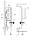
도 8a 내지 도 8c를 참조하면, 다양한 실시예에 따른 케이스(800)에 배치된 스위칭 장치는 시소 키(810)와, 접속 스위치(820)와, 자성 스위치(830)를 포함할 수 있다. 다양한 실시예에 따른 스위칭 장치는 시소 키(810)의 일단 또는 타단의 누름 여부에 따라 동시적으로 온되거나 오프되는 접속 스위치(820) 및 자성 스위치(830)를 포함할 수 있다.8A to 8C , the switching device disposed in the
다양한 실시예에 따른 시소 키(810)는 중간 부분에 힌지 돌기(811)가 구성되어서, 힌지 돌기(811)를 중심으로 제한적인 회전 동작을 수행할 수 있다. 힌지 돌기(811)는 시소 키(810)의 누름 방향과 수직인 방향으로 돌출될 수 있다. 힌지 돌기(811)가 제공하는 힌지 축은 시소 키(810)의 누름 방향과 이격되면서 수직방향으로 향할 수 있다. 시소 키(810)는 제1방향으로 향하는 제1면과, 제1방향과 반대방향으로 향하는 제2방향으로 향하는 제2면을 포함할 수 있다. 예컨대, 시소 키(810)의 제1면은 숨겨지는 면으로서, 접촉 단자(821)와 마그네트(831)가 배치될 수 있는 장착면일 수 있고, 시소 키(810)의 제2면은 외부면으로서, 누름 동작으로 터치되는 표면일 수 있다.In the
다양한 실시예에 따른 시소 키(810)와 케이스(800) 사이에는 이동 공간(s)이 마련되고, 이동 공간(s)에 접속 스위치(820)와 자성 스위치(830)가 배치될 수 있다.A moving space s is provided between the
다양한 실시예에 따른 이동 공간(s)은 시소 키(810)에 의해 제1,2이동 공간으로 분할될 수 있는데, 제1이동 공간은 비워지고, 제2이동 공간에 접속 스위치(820)와 마그네트(831)가 배치될 수 있다. 제2이동 공간에 있는 시소 키(810)의 제2면에 접촉 단자(821)와 마그네트(831)는 중첩되지 않고 대략적으로 평행하게 배치될 수 있다. 또한, 제2이동 공간의 바닥에 택트 스위치(822)가 배치되고, 택트 스위치(822)와 중첩되지 않은 위치에서 근접한 위치의 케이스(800) 내에 자성 센서(832)가 배치될 수 있다. 다양한 실시예에 따른 접촉 단자(821)는 위에서 봤을 때 적어도 일부가 택트 스위치(822)와 중첩되게 배치되고, 마그네트(831)는 적어도 일부가 자성 센서(832)와 중첩되게 배치될 수 있다.The moving space (s) according to various embodiments may be divided into first and second moving spaces by the
도 8b와 같은 상태에서, 접촉 단자(821)는 택트 스위치(822)와 이격되어서 택트 스위치(822)는 오프 상태를 유지하고, 마그네트(831)는 자성 센서(832)와 원거리에 위치하여서 자성 센서(832)는 오프 상태를 유지할 수 있다. 도 8c와 같은 상태에서, 접촉 단자(821)는 택트 스위치(822)를 누르게 되어서 택트 스위치(822)를 온 시키고, 마그네트(831)는 자성 센서(832)와 근거리에 위치하여서 자성 센서(832)는 온 상태가 되어 감지된 신호를 전달할 수 있다In the state as shown in Figure 8b, the
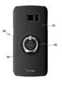
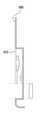
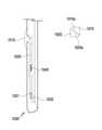
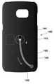
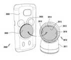
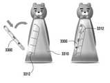
도 9a, 도 9b를 참조하면, 다양한 실시예에 따른 케이스(900)는 버튼(910)의 누름 여부에 따라서 온되거나 오프되는 스위칭 장치를 포함할 수 있다. 버튼(910)을 누르지 않으면 도 9a와 같은 상태가 되어 스위칭 장치는 오프 상태이고, 버튼(910)을 누르면, 도 9b와 같은 상태가 되어 스위칭 장치는 온 상태가 될 수 있다.9A and 9B , the
다앙한 실시예에 따른 스위칭 장치는 버튼(910)과, 차폐 부재(920)와, 자성 스위치(930) 및 탄성체(940)를 포함할 수 있다.The switching device according to various embodiments may include a
다양한 실시예에 따른 버튼(910)은 적어도 일부가 케이스(900)의 제2면에 돌출된 형상으로 배치되어서, 강제적으로 눌러지거나, 누름 힘을 제거하면 원 위치로 복귀할 수 있다.At least a portion of the
다양한 실시예에 따른 차폐재(920)는 버튼(910)에 결합되어서, 버튼(910)이 눌려지면 버튼(910)을 중심으로 회전하고, 눌린 힘을 제거하면, 버튼(910)을 중심으로 역방향으로 회전하여 원위치로 복귀할 수 있다. 예컨대, 차폐재(920)는 평탄한 날개 형상으로 구성되어서, 버튼(910) 누름 유무에 따라서 회전하거나, 회전된 상태에서 원위치로 복귀할 수 있다. 차폐재(920)의 회전 동작에 의해 자성 스위치(930)는 온 상태가 되거나, 오프 상태가 될 수 있다. 도 9a와 같은 상태에서 차폐재(920)는 마그네트(931)와 자성 센서(932) 사이에 배치되어서, 자성 센서(932)는 오프 상태이고, 도 9b와 같은 상태에서 차폐재(920)는 마그네트(931)와 자성 센서(932) 사이에 이탈되어서, 자성 센서(932)는 온 상태일 수 있다.The shielding
다양한 실시예에 따른 자성 스위치(930)는 마그네트(931)와, 마그네트(931)와 중첩되게 배치되는(위에서 봤을 때) 자성 센서(932)를 포함할 수 있다. 마그네트(931)와 자성 센서(932)는 케이스(900)에 각각 배치되되, 그 사이를 차폐재(920)가 위치하거나 이탈한 정도의 거리로 이격될 수 있다.The
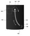
도 9c를 참조하면, 다양한 실시예에 따른 스위칭 장치는 버튼(910)과, 차폐재(920)와, 회전 메커니즘을 포함할 수 있다. 차폐재(920)는 회전 메커니즘에 의해 버튼(910)의 누름에 따라 회전할 수 있고, 탄성체(940) 에 의해 원위치로 복귀할 수 있다.Referring to FIG. 9C , a switching device according to various embodiments may include a
다양한 실시예에 따른 회전 메카니즘은 차폐재(920)에 일체형으로 형성되고, 버튼(910)이 탄성체(940)에 의해 지지된 상태로 이동하는 원통부(951)와, 원통부(951)에 형성된 나선형의 개구(952)와, 상기 버튼(910) 외주면에 형성되되, 상기 개구(952)에 결합되어서, 버튼(910)의 누름에 따라 원통부(951)를 회전시키는 결합 돌기(953)로 구성될 수 있다. 예컨대, 탄성체(940)는 압축 코일 스프링으로 구성되어서, 버튼(910)과 차폐재(920) 사이에서 원통부(951) 내에 배치되어 버튼(910)을 원위치로 복귀시키는 힘을 제공할 수 있다. 탄성체(940)는 버튼(910)이 차폐재(920)에서 멀어지는 방향으로 탄성력을 제공할 수 있다.The rotation mechanism according to various embodiments is integrally formed with the shielding
다양한 실시예에 따른 결합 돌기(953)와 개구(952)의 결합 구조는 버튼(910)의 수직 이동을 차폐재(920)의 회전 이동으로 전환하는 기능을 수행할 수 있다. 버튼(910)의 눌럼짐에 따라 결합 구조에 의해 차폐재(920)는 회전 이동을 진행함으로서, 마그네트와 자성 센서 사이를 개방하거나 폐쇄할 수 있다.The coupling structure of the
도 9d와 같은 상태에서, 차폐재(920)는 마그네트(931)와 자성 센서(932) 사이에 위치하여 마그네트(931)의 자성을 차폐함으로서, 자성 센서(932)는 오프 상태일 수 있다. 이어서, 버튼(910)을 누르면, 도 9e와 같은 상태가 되어서, 결합 돌기(953)는 개구(952)에 구속된 채로 하방으로 이동하고, 차폐재(920)는 회전 동작을 하게 된다. 도 9f와 같은 상태에서, 차폐재(920)는 마그네트와 자성 센서(932) 사이를 이탈하게 되어, 자성 센서(932)는 온 상태가 될 수 있다.In the state shown in FIG. 9D , the shielding
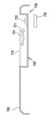
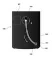
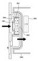
도 10a 내지 도 10d를 참조하면, 다양한 실시예에 따른 케이스(1000)에 구비된 스위칭 장치는 버튼(1010)과, 이동 부재(1020)와, 탄성체(1040)와, 경사 메커니즘 및 자성 스위치(1030)를 포함할 수 있다. 다양한 실시예에 따른 스위칭 장치는 버튼(1010)의 누름에 따라 이동 부재(1020)가 이동하여 자성 스위치(1030)를 온시키거나 오프시킬 수 있게 구성될 수 있다.10A to 10D , the switching device provided in the
다양한 실시예에 따른 버튼(1010)은 케이스(1000)의 제2면에 설치되어서, 누름 동작이 수행될 수 있다. 버튼(1010)을 누르면 도 10b와 같은 상태가 되어서 자성 센서(1032)가 온되고, 버튼(1010)에 가해진 누른 힘을 제거하면, 도 10a와 같은 상태가 되어서 자성 센서(1032)가 오프될 수 있다.The
다양한 실시예에 따른 이동 부재(1020)는 케이스(1000)에 배치되되, 가이드에 의해 이동되는 방향이 가이드될 수 있다. 버튼(1010)을 누르면 경사 메커니즘에 의해 이동 부재(1020)는 자성 스위치(1030)쪽으로 이동하여, 마그네트(1031)가 자성 센서(1032)와 대면상태가 되어서, 자성 센서(1032)가 온될 수 있다. 버튼(1010)에 가해진 누른 힘을 제거하면, 이동 부재(1020)는 버튼(1010)쪽으로 원위치로 이동하고, 마그네트(1031)와 자성 센서(1032)는 멀어져서, 자성 센서(1032)는 오프 상태가 될 수 있다. 예컨대, 이동 부재(1020)의 이동이 선형 이동으로 예시되었지만, 선형 이동으로 한정될 필요는 없으며, 곡형 이동으로 구성가능할 수 있다.The moving
다양한 실시예에 따른 경사 메커니즘은 각각의 경사면의 슬라이딩 운동에 따라 버튼(1010)의 수직 이동이 이동 부재(1020)의 수평 이동으로 전환할 수 있게 한다. 다양한 실시예에 따른 경사 메커니즘은 버튼(1010)에 형성된 제1경사면(1010a)과, 이동 부재(1020)의 일단에 형성되어 제1경사면(1010a)과 슬라이딩하는 제2경사면(1020a)으로 구성될 수 있다.The inclination mechanism according to various embodiments enables the vertical movement of the
다양한 실시예에 따른 제1경사면(1010a)은 버튼(1010) 아래에 형성되어 버튼(1010)과 함께 이동할 수 있다. 다양한 실시예에 따른 제2경사면(1020a)은 이동 부재(1020)의 일단에 형성되되, 상기 제1경사면(1010a)과 연동되게 배치되어서, 버튼(1010)의 눌러짐에 따라 제1경사면(1010a)과 적어도 일부가 면접촉 슬라이딩하는 구동면일 수 있다. 예컨대, 버튼(1010)은 고탄성을 가진 재질로 구성될 수 있다.The first
다양한 실시예에 따른 마그네트(1031)는 이동 부재(1020)의 타단에 배치되어서, 자성 센서(1032)와 원거리에 이격된 상태일 수 있다. 마그네트(1031)는 제2경사면(1020a)과 대치하게 위치할 수 있다. 버튼(1010)이 눌려짐에 따라서 이동 부재(1020)가 자성 센서(1032)로 이동하고, 마그네트(1031)는 자성 센서(1032)와 근거리 대면 상태로 배치되어, 자성 센서(1032)는 온되어서 신호를 전달할 수 있다. 자성 센서(1032)의 오프 상태에서, 위에서 봤을 때 마그네트(1031)는 자성 센서(1032)와 중첩되지 않게 배치될 수 있고, 자성 센서(10320의 온 상태에서, 마그네트(1031)는 적어도 일부가 자성 센서(1032)와 중첩되게 배치될 수 있다.The
다양한 실시예에 따른 탄성체(1040)는 케이스(1000) 소정 위치에서 이동 부재(1020)에 연결되어, 이동 부재(1020)를 원위치로 복귀시키는 힘을 제공할 수 있다. 예컨대, 탄성체(1040)는 인장 코일 스프링을 포함할 수 있다.The
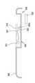
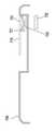
도 11a 내지 도 11d를 참조하면, 다양한 실시예에 따른 케이스(1100)에 장착되는 스위칭 장치는 버튼(1110)과, 연장부(1120) 및 자성 스위치(1130)를 포함할 수 있다. 스위칭 장치는 버튼(1110)의 눌러짐에 따라 연장부(1120)의 길이가 연장되어서, 자성 스위치(1130)를 온시킬 수 있다.11A to 11D , the switching device mounted on the
다양한 실시예에 따른 버튼(1110)은 케이스(1100)의 제2면에 배치되며, 눌러짐에 따라 연장부(1120)를 대략적으로 수평방향으로 연장시킬 수 있다. 버튼(1110)은 케이스(1100) 제2면에 돌출형이나 볼록형으로 배치될 수 있다. 버튼(1110)의 수직방향 눌려짐은 연장부(1120)의 수평 방향 연장으로, 연장부(1120)의 수평 방향 길이는 가변적으로 구성될 수 있다.The
다양한 실시예에 따른 연장부(1120)는 버튼(1110)에서 대략적으로 수평방향으로 연장되는 플레이트 형상으로서, 한쌍으로 구성될 수 있다. 연장부(1120)는 금속 재질로 구성되며, 벤딩된 형상으로 구성될 수 있다. 예컨대, 버튼(1110)이 눌려지면, 버튼(1110)에 작용한 수직방향 힘이 연장부(1120)에 전달되고, 전달된 수직방향 힘은 벤딩된 연장부(1120)를 대략적으로 수평방향으로 선형으로 변형되어서, 연장부(1120)의 수평방향 길이는 연장될 수 있다.The
다양한 실시예에 따른 자성 스위치(1130)는 마그네트(1131)와, 자성 센서(1132)로 구성될 수 있다. 마그네트(1131)는 자성 센서(1132)쪽으로 연장된 연장부(1120)의 단에 배치되고, 자성 센서(1132)는 연장부(1120)의 단에 근접하게 배치될 수 있다. 도 11c와 같은 상태에서, 마그네트(1131)와 자성 센서(1132)는 대략적으로 중첩되지 않고, 상대적으로 원거리 상태일 수 있다. 도 11d와 같은 상태에서, 마그네트(1131)의 적어도 일부와 자성 센서(1132)는 중첩되게 배치되어서, 마그네트(1131)의 자력에 의해 자성 센서(1132)는 온되어 신호를 발생할 수 있다.The
도 12a 내지 도 12d를 참조하면, 다양한 실시예에 따른 케이스(1200)에 실장되는 스위칭 장치는 버튼(1210)과, 회전 레버(1220)와, 경사 메커니즘과, 탄성체(1240) 및 자성 스위치(1230)를 포함할 수 있다. 스위칭 장치는 버튼(1210)에 수직방향으로 가해지는 힘이 경사 메커니즘에 의해 회전 레버(1220)의 수평 회전 이동으로 전환될 수 있다.12A to 12D , the switching device mounted on the
다양한 실시예에 따른 버튼(1210)은 눌러지는 부분으로서, 케이스(1200)의 제2면에 돌출형 또는 볼록형으로 배치될 수 있다. 버튼(1210)은 눌러짐에 따라 회전 레버(1220)의 일측을 수평 상태에서 시계 방향이나 반시계 방향으로 회전시킬 수 있다.The
다양한 실시예에 따른 회전 레버(1220)는 케이스(1200)에 수평하게 배치되되, 힌지축(h)(hinge axis)을 중심으로 회전가능하게 배치될 수 있다. 회전 레버(1220)의 회전은 수평한 상태를 유지하면서 힌지축(h)을 중심으로 회전할 수 있다. 회전 레버(1220)는 일단이 버튼(1210)과 연동하고, 타단이 자성 센서(1232)와 근접하게 배치될 수 있다. 힌지축(h)은 회전 레버(1220)의 일단과 타단 사이에 구비되며, 회전 레버(1220)의 일단이 반시계 방향으로 회전하면, 동시적으로 타단도 반시계 방향으로 회전할 수 있다. 회전 레버(1220)는 일단과 타단 사이에 일측면과 타측면을 구비할 수 있다. 회전 레버(1220)의 일단의 일측면에 대면하게 버튼(1210)이 배치될 수 있고, 타단의 일측면에 자성 센서(1232)가 근접하게 배치될 수 있다.The
다양한 실시예에 따른 경사 메커니즘은 버튼(1210)의 수직 이동을 회전 레버(1220)의 수평한 회전 운동으로 전화하는 구조일 수 있다. 경사 메커니즘은 버튼(1210)에 구비된 제1경사면(1210a)과, 회전 레버의(1220) 일측면에 구비된 제2경사면(1220a)으로 구성될 수 있다. 제1경사면(1210a)과 제2경사면(1220a)은 서로 슬라이딩하며, 버튼(1210)의 수직 이동을 회전 레버(1220)의 수평 회전 운동으로 전환하는 기능을 담당할 수 있다.The inclination mechanism according to various embodiments may have a structure that converts vertical movement of the
다양한 실시예에 따른 탄성체(1240)는 회전 레버(1220)의 타단쪽을 지지하며, 버튼(1210)의 누른 힘을 제거하면, 회전 레버(1220)를 원위치로 복귀하는 힘을 제공할 수 있다. 탄성체(1240)의 일단은 케이스(1200)에 고정되고, 타단은 회전 레버(1220)의 타단 부분에 고정될 수 있다. 예를 들어, 탄성체(1240)는 압축 코일 스프링을 포함할 수 있다.The
다양한 실시예에 따른 자성 스위치(1230)는 회전 레버(1220)의 타단에 배치된 마그네트(1231)와, 케이스(1200)에 배치되되 마그네트(1231)와 근접한 곳에 위치하는 자성 센서(1232)를 포함할 수 있다.The
예컨대, 버튼(1210)을 누르지 않은 도 12c와 같은 상태에서, 마그네트(1231)와 자성 센서(1232)는 중첩되지 않게 배치되어서 자성 센서(1232)는 오프 상태일 수 있다. 이때 탄성체(1240)는 인장상태일 수 있다. 버튼(1210)을 누른 도 12d와 같은 상태면, 회전 레버(1220)는 반시계 방향으로 이동하고, 마그네트(1231)의 적어도 일부는 자성 센서(1232)쪽으로 이동한 후에 자성 센서(1232)와 중첩되게 배치되어서, 자성 센서(1232)는 온 상태일 수 있다. 이때, 탄성체(1240)는 압축 상태일 수 있다.For example, in a state as shown in FIG. 12C in which the
도 13a 내지 도 13d를 참조하면, 다양한 실시예에 따른 케이스(1300)에 배치된 스위칭 장치는 버튼(1310)과, 회전 메커니즘(1320), 탄성체(1340) 및 자성 스위치(1330)를 포함할 수 있다.13A to 13D, the switching device disposed in the
다양한 실시예에 따른 버튼(1310)은 눌러지는 부분으로서, 케이스(1300)의 제2면에 돌출형 또는 볼록형으로 배치될 수 있다. 버튼(1310)은 눌러짐에 따라 회전 메카니즘(1320)의 일측 및 타측을 회전시킬 수 있다.The
다양한 실시예에 따른 회전 메카니즘(1320)는 케이스(1300)에 수평하게 배치되되, 힌지축(h)을 중심으로 회전가능하게 배치될 수 있다. 회전 메카니즘(1320)는 일단이 버튼(1310)과 연동하고, 타단이 자성 센서(1332)와 근접하게 배치될 수 있다. 힌지축(h)은 회전 메카니즘(1320)의 일단과 타단 사이에 구비되며, 회전 메카니즘(1320)의 일단이 반시계 방향으로 회전하면, 동시적으로 타단도 반시계 방향으로 회전할 수 있다. 회전 메카니즘(1320)의 일단의 일측면에 대면하게 버튼(1310)이 배치될 수 있고, 타단의 일측면에 자성 센서(1332)가 근접하게 배치될 수 있다.The
다양한 실시예에 따른 탄성체(1340)는 회전 메카니즘(1320)을 지지하며, 버튼(1310)의 누른 힘을 제거하면, 회전 메카니즘(1320)을 원위치로 복귀하는 힘을 제공할 수 있다. 탄성체(1340)의 일단은 케이스(1300)에 고정되고, 타단은 회전 메카니즘(1320)에 고정될 수 있다. 예를 들어, 탄성체(1340)는 압축 코일 스프링을 포함할 수 있다.The
다양한 실시예에 따른 자성 스위치(1330)는 회전 메카니즘(1320)의 타단에 배치된 마그네트(1331)와, 케이스(1300)에 배치되되 마그네트(1331)와 근접한 곳에 위치하는 자성 센서(1332)를 포함할 수 있다.The
예컨대, 버튼(1310)을 누르지 않은 도 13c와 같은 상태에서, 마그네트(1331)와 자성 센서(1332)는 근거리로 배치되어서 자성 센서(1332)는 오프 상태일 수 있다. 이때 탄성체(1340)는 인장 상태일 수 있다. 버튼(1310)을 누른 도 13d와 같은 상태면, 회전 메카니즘(1320)는 반시계 방향으로 이동하고, 마그네트(1331)의 적어도 일부는 자성 센서(1332)쪽으로 이동한 후에 자성 센서(1332)와 근접하게 배치되어서, 자성 센서(1232)는 온 상태일 수 있다. 이때, 탄성체(1340)는 압축 상태일 수 있다.For example, in a state as shown in FIG. 13C in which the
도 14a 내지 도 14d를 참조하면, 다양한 실시예에 따른 케이스(1400)의 제2면에 실장되는 스위칭 장치는 버튼(1410)과, 가이드 구조(1441,1442)와, 연성 재질부(1420) 및 자성 스위치(1430)를 포함할 수 있다.14A to 14D , the switching device mounted on the second surface of the
다양한 실시예에 따른 케이스(1400)는 버튼(1410)의 수평 방향 슬라이딩 이동을 위한 가이드 레일(1441)이 형성될 수 있다. 가이드 레일(1441) 이내에서 버튼(1410)은 제한적인 슬라이딩 이동을 할 수 있다. 가이드 레일(1441)은 홈 형상이나 개구 형상으로 구성될 수 있고, 위에서 봤을 때, 일방향으로 연장된 길죽한 형상일 수 있다. 가이드 레일(1441)은 선형(liner)이나 곡형(curved)으로 구성될 수 있다.In the
다양한 실시예에 따른 버튼(1410)은 케이스(1400)의 제2면에서 가이드 레일(1441)에 의해 수평방향으로 슬라이딩하는 이동 부재일 수 있다. 버튼(1410)은 연성 재질부(1420)와 일체형으로 연결될 수 있다. 버튼(1410)은 케이스(1400) 외부로 노출되는 부분이고, 연성(flexible) 재질부(1420)는 케이스 내부로 숨겨지는 부분일 수 있다.The
다양한 실시예에 따른 가이드 구조(1442)는 버튼(1410)의 슬라이딩 이동에 따라서 연성 재질부(1420)의 이동을 지지하면서 가이드하는 구조일 수 있다. 예컨대 가이드 구조(1442)는 홈 형상으로 구성될 수 있고, 선형이나 곡형으로 구성될 수 있다. 도 14a 내지 도 14d는 곡형의 가이드 구조(1442)가 예시되었다. 가이드 구조(1442)의 일단 영역은 가이드 레일(1441)과 연결되고, 타단 영역은 자성 센서(1432)가 배치될 수 있다.The
다양한 실시예에 따른 연성 재질부(1420)는 가이드 구조(1441)에 수용되어서, 가이드 구조(1441)를 따라 슬라이딩하는 이동 부재일 수 있다. 연성 재질부(1420)의 일단은 버튼(1410)과 연결되고, 타단은 마그네트(1431)가 배치될 수 있다. 예컨대 연성 재질부(1420)는 사출 재질로서, 고밀도 탄성 PU 젤 재질이거나 연성 PC 사출 재질로 구성될 수 있고, 러버나 실리콘 또는 연성 플라스틱 중 어느 하나를 포함할 수 있다.The
다양한 실시예에 따른 자성 스위치(1430)는 연성 재질부(1420) 타단에 배치된 마그네트(1431)와, 가이드 구조(1442) 타단에 근접하게 배치된 자성 센서(1432)를 포함할 수 있다. 도 14c와 같은 상태에서, 마그네트(1431)는 자성 센서(1432)와 위에서 봤을 때 중첩하지 않게 배치되어 자성 센서(1432)는 오프 상태일 수 있다. 도 14d와 같은 상태에서, 마그네트(1431)는 자성 센서(1432)와 위에서 봤을 때 중첩되게 배치(접촉상태일 수 있다)되어서, 자성 센서(1432)는 온 상태일 수 있고, 신호를 전달할 수 있다.The
도 15a, 도 15b를 참조하면, 다양한 실시예에 따른 케이스(1500)에 배치된 스위칭 장치는 버튼(1510)과, 회전 레버(1520)와, 자성 스위치(1530)를 포함할 수 있다.15A and 15B , the switching device disposed in the
다양한 실시예에 따른 버튼(1510)은 케이스(1500) 제2면에서 수평 슬라이딩하는 이동 부재로서, 가이드 개구(1541)를 따라 이동될 수 있다.The
다양한 실시예에 따른 회전 레버(1520)는 힌지축(h)을 중심으로 회전가능하게 배치되며, 수평으로 이동할 수 있다. 회전 레버(1520)의 일단은 버튼(1510)이 일체형으로 연결되고, 타단은 마그네트(1531)가 일체형으로 장착될 수 있다. 회전 레버(1520)의 일단이 반시계 방향으로 회전하면, 동시적으로 타단이 반시계 방향으로 회전할 수 있다. 힌지축(h)은 회전 레버(1520)의 일단과 타단 사이에 배치될 수 있고, 회전 레버(1520)를 관통하는 수직 방향으로 향할 수 있다.The
다양한 실시예에 따른 자성 스위치(1530)는 회전 레버(1520)의 타단에 설치된 마그네트(1531)와, 회전 레버(1520)의 타단에 근접하게 배치된 자성 센서(1532)를 포함할 수 있다.The
도 15a와 같은 상태에서, 마그네트(1531)는 위에서 봤을 때 자성 센서(1532)와 중첩되지 않게 배치되어 자성 센서(1532)가 오프 상태이고, 도 15b와 같은 상태에서, 마그네트(1531)는 자성 센서(1532)와 중첩되게 배치되어서 자성 센서(1532)가 온 상태가 되어서 발생한 신호를 전달할 수 있다. 전달된 신호에 의해 근거리 통신 서비스가 활성화될 수 있다.15A, the
도 16a, 도 16b를 참조하면, 다양한 실시예에 따른 케이스(1600) 제2면에 실장된 스위칭 장치는 슬라이딩 버튼(1610)과, 회전 레버(1620)와, 자성 스위치(1630)를 포함할 수 있다.16A and 16B , the switching device mounted on the second surface of the
다양한 실시예에 따른 슬라이딩 버튼(1610)은 수평방향으로 케이스(1600)의 제2면에서 슬라이딩할 수 있다. 케이스(1600) 제2면에는 슬라이딩 버튼(1610)의 이동을 가이드하는 가이드 개구(1641)가 형성될 수 있다. 가이드 개구(1641)는 선형이가 곡형으로 구성될 수 있으며, 슬라이딩 버튼(1610)과 회전 레버(1620)의 연결부가 위치하며, 상기 가이드 개구(1641) 내에서 슬라이딩 버튼(1610)은 이동할 수 있다. 예컨대, 슬라이딩 버튼(1610)은 슬라이딩 이동을 수행하고, 슬라이딩 후에 택트 스위치(s)와 접촉하며, 택트 스위치(s)가 온되어서, 근거리 통신 모듈(NFC)을 동작시킬 수 있다.The sliding
다양한 실시예에 따른 회전 레버(1620)는 버튼(1610)의 슬라이딩 이동에 연동되어 수평한 상태를 유지한 채로 회전하는 회전 부재로서, 힌지축(h)을 중심으로 시계 방향이나 반시계 방향으로 회전할 수 있다. 회전 레버(1620)의 일단부는 슬라이딩 버튼(1610)과 접촉하는 부분이고, 타단부는 자성 센서(1632)를 개폐하는 부분일 수 있다. 힌지축(h)은 회전 레버(1620)의 대략적인 중간 부분에 위치하며, 수직방향으로 향할 수 있다.The
다양한 실시예에 따른 자성 스위치(1630)는 마그네트(1631)와 자성 센서(1632)로 구성될 수 있다. 마그네트(1631)는 회전 레버(1620)의 타단부에 배치되어서, 회전 레버(1620)의 제한적인 회전 동작에 따라서 자성 센서(1632)를 온시키거나 오프시킬 수 있다.The
슬라이딩 버튼(1610)을 가이드 개구(1641)의 일단에서 타단으로 이동시키면, 동시적으로 택트 스위치(s)는 온되고, 회전 레버(1620)는 시계방향으로 회전하여 마그네트(1631)는 자성 센서(1632)에서 이탈된다. 위에서 봤을 때, 마그네트(1631)는 자성 센서(1632)와 중첩되지 않게 배치될 수 있다. 슬라이딩 버튼(1610)을 가이드 개구(1641)의 타단에서 일단으로 이동시키면, 동시적으로 회전 레버(1620)는 반시계 방향으로 회전하여 마그네트(1631)는 자성 센서(1632)와 접촉 또는 대면하는 상태가 될 수 있다. 위에서 봤을 때, 마그네트(1631)는 적어도 일부가 자성 센서(1632)와 중첩되게 배치될 수 있다.When the sliding
도 17a, 도 17b를 참조하면, 다양한 실시예에 따른 케이스(1700) 제2면에 배치되는 스위칭 장치는 회전 버튼(1710)과, 가이드 개구(1741)와, 연결 레버(1720)와, 가이드 면(1741) 및 자성 스위치(1730)를 포함할 수 있다.Referring to FIGS. 17A and 17B , the switching device disposed on the second surface of the
다양한 실시예에 따른 회전 버튼(1710)은 케이스(1700) 제2면에 힌지축을 중심으로 회전가능하게 배치될 수 있다. 예컨대 회전 버튼(1710)은 일단 부분은 힌지축이 위치하고, 타단 부분은 연결 레버(1720)와 연결되는 부분일 수 있다. 회전 레버(1720)의 타단 부분은 가이드 개구(1741)를 따라서 이동할 수 있다.The
다양한 실시예에 따른 가이드 개구(1741)는 회전 버튼(1710)의 타단 부분이 구속된 상태로 이동하고, 회전 레버(1720)의 일단이 구속된 상태로 이동하는 이동 경로일 수 있다. 가이드 개구(1741)는 곡률을 가지게 구성될 수 있다. 가이드 개구(1741)의 타단 부분에는 택트 스위치(s)가 배치될 수 있다.The
다양한 실시예에 따른 연결 레버(1720)는 수평한 상태를 유지한 채로 일정한 궤적으로 이동할 수 있다. 연결 레버(1720)의 일단 부분은 회전 버튼(1710)의 타단에 회전가능하게 연결되어 가이드 개구(1741)을 따라 이동가능하고, 연결 레버(1720)의 타단 부분은 마그네트(1731)가 장착되는 부분으로서, 가이드 면(1742)을 따라서 이동하여 자성 센서(1732)와 중첩되지 않게 배치되거나, 중첩되게 배치될 수 있다. 연결 레버(1720)는 연결 바, 슬라이딩 회전 바, 연결 링크, 등으로 달리 지칭할 수 있다.The
다양한 실시예에 따른 자성 스위치(1730)는 마그네트(1731)와 자성 센서(1732)로 구성될 수 있다. 마그네트(1731)는 연결 레버(1720)의 타단에 배치되고, 자성 센서(1732)는 케이스(1700) 내에 마그네트(1731)와 근접한 곳에 배치될 수 있다.The
도 17a와 같은 상태에서, 마그네트(1731)는 자성 센서(1732)와 이격된 상태라서, 자성 센서(1732)는 오프상태이고, 도 17b와 같은 회전 버튼(1710)을 회전시키면, 연결 레버(1720)는 일정한 궤적을 가지게 이동하며, 그의 단부에 배치된 마그네트(1731)는 가이드 면(1742)을 따라 이동한 후에 자성 센서(1732) 상에 적어도 일부가 중첩되게 배치될 수 있다. 마그네트(1731)가 자성 센서(1732)에 중첩되게 배치되어서, 자성 센서(1732)는 온되어 신호를 전달할 수 있다. 동시적으로 택트 스위치(s)로 온되어 신호를 전달할 수 있다.In the state shown in FIG. 17A , since the
도 18a, 도18b를 참조하면, 다양한 실시예에 따른 케이스(1800) 제2면에 배치된 스위칭 장치는 슬라이딩 버튼(1810)과, 적어도 두개의 연결 레버(1821,1822)와, 기어 메커니즘(1850)과, 자성 스위치(1830)를 포함할 수 있다.Referring to FIGS. 18A and 18B , the switching device disposed on the second surface of the
다양한 실시예에 따른 슬라이딩 버튼(1810)은 케이스(1800) 제2면에 형성된 가이드 개구(1841)를 따라 이동하되, 케이스(1800) 제2면상에서 수평한 상태를 유지하면서 이동할 수 있다. 슬라이딩 버튼(1810)은 슬라이딩 이동으로 자성 스위치(1830)를 온시키고, 동시적으로 택트 스위치(s)를 온시킬 수 있다. 슬라이딩 버튼(1810)의 이동은 선형이나 곡형으로 구성될 수 있다.The sliding
다양한 실시예에 따른 적어도 하나 이상의 연결 레버는 제1,2연결 레버(1821,1822)로 구성되며, 제1,2연결 레버(1821,1822) 사이에 기어 메커니즘(1850)이 배치되어서, 서로 연동되는 구조로 구성될 수 있다. 기어 메커니즘(1850)은 제1연결 레버(1821)에 구비된 제1기어와, 제2연결 레버91822)에 구비된 제2기어를 포함할 수 있다.At least one or more connection levers according to various embodiments are composed of first and
제1연결 레버(1821)는 일단이 슬라이딩 버튼(1810)의 일단 부분에 회전가능하게 연결되고, 타단이 기어 메커니즘(1850)에 연결될 수 있다. 제1연결 레버(1821)의 타단은 상기 제1기어가 구비될 수 있다. 제2연결 레버(1822)는 일단에 마그네트(1831)가 배치된 상태로 자성 센서(1832)와 근접하게 배치되고, 타단이 기어 메커니즘(1850)에 연결될 수 있다. 제2연결 레버(1822)의 타단은 제1기어와 맞물린 제2기어가 구비될 수 있다. 슬라이딩 버튼(1810)의 이동과 제1,2기어의 맞물림에 의해 각각의 제1,2연결 레버(1821,1822)는 수평한 상태를 유지한 채로 궤적을 가지게 각각 이동하고, 제2연결 레버(1822)의 일단은 자성 센서(1832)와 중첩되게 배치되거나 중첩되게 배치되지 않을 수 있다. 마그네트(1831)가 자성 센서(1832)와 중첩되게 배치되면, 자성 센서(1832)는 온되어서, 감지 신호를 전달할 수 있다.다양한 실시예에 따른 자성 스위치(1830)는 제2연결 레버(1822)의 타단에 배치된 마그네트(1831)와, 마그네트(1831)와 근접한 곳에 배치된 자성 센서(1832)를 포함할 수 있다.One end of the
도 19a, 도 19b를 참조하면, 다양한 실시예에 따른 케이스(1900)에 실장되는 스위칭 장치는 슬라이딩 버튼(1910)과, 회로부(1920)와, 통신 모듈부(m)와, 연성 회로부(f) 및 자성 스위치(1930)를 포함할 수 있다.19A and 19B , the switching device mounted on the
다양한 실시예에 따른 슬라이딩 버튼(1910)은 케이스(1900)의 제2면에 수평 방향으로 슬라이딩 이동가능하게 구성될 수 있다. 케이스(1900) 제2면에는 가이드 홈(1940)이 형성되고, 가이드 홈(1940) 내에서 슬라이딩 버튼(1910)의 제한적인 슬라이딩 이동이 가능할 수 있다.The sliding
다양한 실시예에 따른 회로부(1920)는 슬라이딩 버튼(1910)에 구비되되, 적어도 두개 이상의 버튼부(1921)를 구비할 수 있다. 회로부(1920)는 일측 모서리에 마그네트(1931)가 포함될 수 있다. 버튼부(1921)는 항시 근거리 통신 모듈(m)에 연성 회로(f)에 의해 전기적으로 연결될 수 있다. 버튼부(1921)는 눌러짐에 따라 신호가 발생할 수 있다.The
다양한 실시예에 따른 케이스(1900)에 실장된 자성 스위치(1930)는 슬라이딩 버튼(1910)에 구비된 마그네트(1931)와, 케이스(1900) 내에 배치된 자성 센서(1932)를 포함할 수 있다. 슬라이딩 버튼(1910)의 이동에 따라 자성 센서(1932)는 온되거나 오프될 수 있다. 예를 들어, 위에서 봤을 때, 마그네트(1931)가 자성 센서(1932)와 중첩하지 않는 위치에 배치되면, 자성 센서(1932)는 오프상태일 수 있다. 마그네트(1931)가 자성 센서(1932)와 중첩하는 위치에 배치되면, 자성 센서(1932)는 온상태가 되어서, 감지 신호를 전달할 수 있다. 마그네트(1931)와 자성 센서(1932)가 중첩되지 않게 배치된 상태가 도 19c에 도시되었고, 마그네트(1931)와 자성 센서(1932)가 중첩되게 배치된 상태가 도 19d에 도시되었다.The
도 20a 내지 도 20c를 참조하면, 다양한 실시예에 따른 케이스(2000)에 배치된 스위칭 장치는 슬라이딩 부재(2010)와, 마이크로 스위치(2020)와, 자성 스위치(2030)를 포함할 수 있다.20A to 20C , the switching device disposed in the
다양한 실시예에 따른 스위칭 장치는 슬라이딩 부재(2010)의 이동에 따라 마이크로 스위치(2020)를 온시키고, 동시적으로 자성 스위치(2030)를 온시켜서, 전자 장치의 슬립 상태 또는 락 스크린 상태에서도 하나의 모션으로 근거리 통신 모듈(m)의 서비스 이용이 가능할 수 있다.The switching device according to various embodiments turns on the
다양한 실시예에 따른 케이스(2000)는 스위칭 장치가 배치되는 바텀 파트(2001)를 포함할 수 있다. 바텀 파트(2010) 상에 슬라이딩 부재(2010)와, 마이크로 스위치(2020)가 배치될 수 있다.The
다양한 실시예에 따른 슬라이딩 부재(2010)는 바텀 파트(2001) 상에서 수평 상태를 유지하면서, 바텀 바트(2001)와 대면 상태를 유지하면서 이동하는 이동 부재로서, 슬라이딩 유무에 따라 마이크로 스위치(2020) 및 자성 스위치(2030)가 동시적으로 온되거 오프될 수 있다. 도 20a와 같은 슬라이딩 부재가(2010) 일측에 위치한 경우, 스위칭 장치는 오프 상태이고, 도 20b와 같은 슬라이딩 부재(2010)가 타측에 이동하여 위치한 경우, 스위칭 장치는 온 상태일 수 있다. 슬라이딩 부재(2010)는 슬라이딩에 따라 마이크로 스위치(2020)를 온시키기 위한 트리거(trigger)(2011)가 구성될 수 있다. 트리거(2011)는 슬라이딩 부재(2010)에 돌기 형상으로 구성되어서, 슬라이딩 부재(2020)의 슬라이딩 동작 시에 마이크로 스위치(2020)의 액츄에이터를 밀어서, 마이크로 스위치(2020)를 온 상태로 되게 하고, 슬라이딩 부재(2010)의 역방향 슬라이딩 동작 시에 마이크로 스위치(2020)의 액츄에이터를 밀어서, 마이크로 스위치(2020)를 온상태로 되게 할 수 있다. 즉, 슬라이딩 부재의 트리거(2011)는 슬라이딩 부재(2010)의 이동에 따라 마이크로 스위치(2020)의 액츄에이터와 연동되게 실장될 수 있다. 예컨대 트리거(2011)는 슬라이딩 부재(2010)의 중간 정도의 부분에 형성될 수 있다. 또한, 슬라이딩 부재(2010)는 소정 영역에 마그네트(2031)가 구비될 수 있다.The sliding
다양한 실시예에 따른 마이크로 스위치(2020)는 바텀 파트(2001)에 배치되되, 슬라이딩 부재의 트리거(2011)와 대면할 수 있게 배치될 수 있다. 즉, 마이크로 스위치(2020)의 액츄에이터는 트리거(2011)와 대면하게 배치되되, 슬라이딩 부재(2010)의 이동 유무에 따라 연동하게 바텀 파트(2001) 상에 배치될 수 있다. 마이크로 스위치(2020)는 근거리 통신 모듈(m)에 전기적으로 연결될 수 있다. 마이크로 스위치(2020)가 온되면, 근거리 통신 모듈(m)이 동작하여, 근거리 통신 모듈(m)을 이용한 서비스를 제공받을 수 있다.The
다양한 실시예에 따른 자성 스위치(2030)는 슬라이딩 부재(2020)에 배치된 마그네트(2031)와, 케이스(2000)에 배치된 자성 센서(2032)를 포함할 수 있다. 위에서 봤을 때, 마그네트(2031)와 자성 센서(2032)가 중첩되지 않은 상태이면 자성 센서(2032)는 오프된 상태이고, 마그네트(2031)와 자성 센서(2032)가 중첩된 위치에 배치되면 자성 센서(2032)를 온 상태일 수 있다.The
도 20a와 같은 슬라이딩 부재(2010) 이동 전 상태에서 마이크로 스위치(2020) 및 자성 센서(2032)는 오프상태이고, 도 20b와 같은 슬라이딩 부재(2010) 이동 후 상태에서 마이크로 스위치(2020) 및 자성 센서(2032)는 온 상태일 수 있다. 마이크로 스위치를 사용하여, 소형화가 가능할 수 있다.The
도 21a 내지 도 21c를 참조하면, 다양한 실시예에 따른 케이스(2100)에 실장되는 스위칭 장치는 접이형 부재(2110,2120)와 자성 스위치(2130)를 포함할 수 있다. 스위칭 장치는 접이형 부재(2110,2120)를 접는 경우에 온 상태일 수 있다.21A to 21C , a switching device mounted on a
다양한 실시예에 따른 접이형 부재는 고정 부재(2110)와, 접이 부재(2120) 및 연결 부재(2115)를 포함할 수 있다. 고정 부재(2110)는 케이스(2100)의 제2면에 고정될 수 있다. 접이 부재(2120)는 연결 부재(2115)에 의해 고정 부재(2110)에서 접히거나 펼쳐지게 연결될 수 있다. 연결 부재(2115)는 연성 재질로 구성되어서, 접이 부재(2120)의 접이축(folding axis)을 제공할 수 있다. 접이 축은 케이스(2100)의 가로 방향과 평행한 방향으로 향할 수 있다. 연결 부재(2115)는 연성 회로기판을 포함할 수 있다. 즉, 연결 부재(2115)에 의해 고정 부재(2110)와 접이 부재(2120)는 전기적으로 연결될 수 있고, 물리적으로 연결될 수 있다.The foldable member according to various embodiments may include a fixing
접이 부재(2120)가 고정 부재(2110)에 접힌 경우, 접힌 상태를 잡아주는 홀딩 장치가 더 구비될 수 있다. 홀딩 장치는 고정 부재(2110)에 구비된 적어도 하나 이상의 홈(2111)과, 접이 부재(2120)에 형성된, 홈(2111)에 결합되는 적어도 하나 이상의 돌기(2121)를 포함할 수 있다. 예컨대, 고정 부재(2110)의 양측 모서리 영역에 재1,2홈(2111)이 형성되고, 접이 부재(2120)의 양 모서리 영역에 제1,2돌기(2121,2131)가 배치될 수 있다. 접이 부재(2120)가 고정 부재(2110)에 접힌 상태가 되면, 제1,2돌기(2121,2131)는 제1,2홈(2111)에 각각 결합되어서, 접힌 상태를 잡아줄 수 있다.When the
다양한 실시예에 따른 접이 부재(2120)는 제1면에 적어도 하나 이상의 버튼부(2112)가 배치될 수 있다. 선택된 버튼부(2112)가 눌려지면, 연결 부재(2115), 즉 연성 회로기판에 의해 신호 전달이 가능할 수 있다.At least one
다양한 실시예에 따른 자성 스위치(2130)는 접이 부재(2120)에 배치된 마그네트(2131)와, 전자 장치에 배치된 자성 센서(2132)를 포함할 수 있다. 마그네트(2131)는 접이 부재(2120)에 형성된 하나의 돌기를 자성체 재질로 구성할 수 있다. 즉 마그네트(2131)는 돌기 형상으로 접이 부재에 적어도 한 개 이상 배치될 수 있다. 예컨대, 자성 센서(2132)는 마그네트(2131)과 대응하는 하나의 홈(2111)에 구성되거나, 하나의 홈(2111)에 인접한 곳, 예컨대 케이스(2100) 내부의 대응하는 위치에 하나의 홈(2111)과 대면하게 배치될 수 있다.The
도 21a와 같이 접이 부재(2120)가 고정 부재(2110)에서 펼쳐진 상태(unfolding state)이면, 자성 센서(2132)는 오프 상태이고, 버튼부(2112)는 조작 불가능상태이며, 오프 상태일 수 있다. 마그네트(2131)와 자성 센서(2132)는 중첩되지 않게 배치된 상태일 수 있다.When the
도 21b와 같이 접이 부재(2120)가 고정 부재(2110)에서 접혀진 상태(folding state)이면, 마그네트(2131)는 자성 센서(2132)와 대면한 상태가 되어 온상태일 수 있다. 버튼부(2112)는 조작가능한 상태이며, 마그네트(2131)와 자성 센서(2132)는 중첩되게 배치된 상태일 수 있다.When the
도 22a, 도 22b를 참조하면, 다양한 실시예에 따른 케이스(2200)에 실장되는 스위칭 장치는 접이형 부재와 자성 스위치를 포함할 수 있다. 스위칭 장치는 접이형 부재를 접는 경우에 온 상태일 수 있다.22A and 22B , a switching device mounted on a
다양한 실시예에 따른 접이형 부재는 삼각형 고정 부재(2210)와, 삼각형 접이 부재(2220) 및 연결 부재(2215)를 포함할 수 있다. 고정 부재(2210)는 케이스(2200)의 제2면에 고정될 수 있다. 삼각형 접이 부재(2220)는 연결 부재(2215)에 의해 삼각형 고정 부재(2210)에서 접히거나 펼쳐지게 연결될 수 있다. 연결 부재(2215)는 연성 재질로 구성되어서, 삼각형 접이 부재(2220)의 접이축을 제공할 수 있다. 접이 축은 삼각형 고정 부재(2210)와 삼각형 접이 부재(2220)가 펼쳐진 상태일 경우, 삼각형 고정 부재(2210)와 삼각형 접이 부재(2220)를 구분하는 대각선 방향으로 향할 수 있다. 연결 부재(2215)는 연성 회로기판을 포함할 수 있다. 즉, 연결 부재(2215)에 의해 삼각형 고정 부재(2210)와 삼각형 접이 부재(2220)는 전기적으로 연결될 수 있고, 물리적으로 연결될 수 있다.The foldable member according to various embodiments may include a
삼각형 접이 부재(2220)가 삼각형 고정 부재(2210)에 접힌 경우, 접힌 상태를 잡아주는 홀딩 장치가 더 구비될 수 있다. 홀딩 장치는 삼각형 고정 부재(2210)에 구비된 적어도 하나 이상의 홈(2211)과, 삼각형 접이 부재(2220)에 형성된, 홈(2211)에 결합되는 적어도 하나 이상의 돌기(2221)를 포함할 수 있다. 예컨대, 삼각형 접이 부재(2220)가 삼각형 고정 부재(2210)에 접힌 상태가 되면, 돌기(2221)는 홈(2211)에 각각 결합되어서, 접힌 상태를 잡아줄 수 있다.When the
다양한 실시예에 따른 삼각형 접이 부재(2220)는 제1면에 적어도 하나 이상의 버튼부(2222)가 배치될 수 있다. 선택된 버튼부(2222)가 눌려지면, 연결 부재(2215), 즉 연성 회로기판에 의해 신호 전달이 가능할 수 있다.At least one
다양한 실시예에 따른 자성 스위치는 삼각형 접이 부재(2220)에 배치된 마그네트(2221)와, 전자 장치에 배치된 자성 센서(미도시)를 포함할 수 있다. 마그네트(2221)는 삼각형 접이 부재(2220)에 형성된 하나의 돌기를 자성체 재질로 구성할 수 있다. 즉 마그네트(2221)는 돌기 형상으로 삼각형 접이 부재(2220)에 적어도 한 개 이상 배치될 수 있다.The magnetic switch according to various embodiments may include a
도 22a와 같이 삼각형 접이 부재(2220)가 삼각형 고정 부재(2210)에서 펼쳐진 상태(unfolding state)이면, 자성 센서는 오프 상태이고, 버튼부는 조작 불가능상태이며, 오프 상태일 수 있다. 마그네트(2221)와 자성 센서는 중첩되지 않게 배치된 상태일 수 있다.As shown in FIG. 22A , when the
도 22b와 같이 삼각형 접이 부재(2220)가 삼각형 고정 부재(2210)에서 접혀진 상태(folding state)이면, 마그네트(2221)는 자성 센서와 대면한 상태가 되어 온상태일 수 있다. 버튼부(2222)는 조작가능한 상태이며, 마그네트(2221)와 자성 센서는 중첩되게 배치된 상태일 수 있다.As shown in FIG. 22B , when the
도 23a 내지 도 23c를 참조하면, 다양한 실시예에 따른 케이스(2300)에 장착된 스위칭 장치는 회전 휠(2310)과, 기어 이동 부재(2322)와, 접촉 스위치(s) 및 자성 스위치(2330)를 포함할 수 있다.23A to 23C , the switching device mounted on the
다양한 실시예에 따른 케이스(2300)는 제2면에 스위칭 장치가 조작가능하게 장착되며, 회전 휠(2310)의 적어도 일부가 노출되고, 나머지 구성 요소는 스위치 박스(2320) 내에 배치될 수 있다. 회전 휠(2310)의 노출된 적어도 일부가 조작가능한 부분일 수 있다. 회전 휠(2310)의 회전에 따라 접촉 스위치(s)와 자성 스위치(2330)는 온 상태가 될 수 있다.In the
다양한 실시예에 따른 회전 휠(2310)은 일부 만이 스위치 박스(2320)에서 노출되게 배치되고, 나머지는 숨겨지게 배치될 수 있다. 회전 휠(2310)은 둘레를 기어 돌기로 하여 회전 동작을 용이하게 하며, 케이스(2300)의 제2면에 평행하게 대면하게 회전가능하게 배치될 수 있다. 회전 휠(2310)의 회전 동작에 따라 기어 이동 부재(2322)는 선형 이동을 하게 배치될 수 있다.Only a portion of the
다양한 실시예에 따른 회전 휠(2310)은 곡률을 가지는 개구(2311)가 형성되고, 개구(2311) 내에 접촉 스위치(s)가 배치될 수 있다. 즉, 회전 횔(2310)과 접촉 스위치(s)는 중첩되지 않게 배치되고, 회전 휠(2310) 내에 접촉 스위치(s)가 배치될 수 있다. 회전 휠(2310)의 회전 유무에 따라 접촉 스위치(s)는 온되거나 오프될 수 있다. 개구(2311)는 회전 휠(2310)의 회전축(h)과 기어 돌기 사이에 위치할 수 있다. 개구(2311)의 일측에 있는 일단이 접촉 스위치(s)와 접촉하면 접촉 스위치(s)는 온될 수 있다.In the
다양한 실시예에 따른 기어 이동 부재(2322)는 회전 휠(2310)의 회전 운동에 따라 좌우로 선형이등을 하는 이동 부재일 수 있다. 기어 이동 부재(2322)는 적어도 하나 이상의 가이드 개구(2323)가 구비되어서, 이동 거리가 제한될 수 있다. 가이드 개구(2323)와 삽입되는 가이드 돌기(2324)가 케이스에 형성되어서, 가이드 개구(2323)와 가이드 돌기(2324) 간의 결합 구조에 의해, 기어 이동 부재(2322)는 제한적인 이동을 할 수 있다. 기어 이동 부재(2322)는 일측으로 기어 부분(2322a)과, 타측으로 마그네트(2331)를 구비할 수 있다. 기어 부분(2322a)은 기어 돌기와 맞물린 상태로 배치되어, 회전 휠(2310)의 회전 이동을 기어 이동 부재(2322)의 선형 이동으로 전환하는 기능을 담당할 수 있다. 기어 부분(2322a)은 기어 이동 부재(2322)의 상단에 선형으로 배열될 수 있다.The
다양한 실시예에 따른 자성 스위치(2330)는 기어 이동 부재(2322)에 배치된 마그네트(2331)와, 케이스(2300)에 배치된 자성 센서(2332)를 포함할 수 있다. 위에서 봤을 때, 마그네트(2331)와 자성 센서(2332)가 중첩되지 않게 배치되면, 자성 센서는 오프 상태이고, 마그네트(2331)와 자성 센서(2332)가 중첩되게 배치되면, 자성 센서는 온 상태라서, 신호를 전달할 수 있다.The
도 23b와 같은 회전 휠(2310)이 소정의 각도로 회전한 경우, 개구(2311)의 일단이 접촉 스위치(s)와 접촉하여 온상태가 되고, 마그네트(2331)가 자성 센서(2332)와 중첩되게 대면하게 배치되어서, 자성 센서(2332)가 온 상태가 될 수 있다. 접촉 스위치(s)와 자성 센서(2332)는 대략적으로 동시적으로 온/오프 상태가 될 수 있다.When the
도 24a 내지 도 24c를 참조하면, 다양한 실시예에 따른 케이스(2400)에 장착되는 스위칭 장치는 볼펜의 개폐 원리를 이용하여 구성할 수 있다. 즉, 스위칭 장치는 버튼(2410)을 누르면, 구비된 접촉 스위치(s)와 자성 스위치(2430)가 온 상태가 될 수 있고, 다시 한번 버튼을 누르면, 온 상태의 접촉 스위치(s)와 자성 스위치(2430)를 오프 상태가 될 수 있다.24A to 24C , the switching device mounted on the
다양한 실시예에 따른 스위칭 장치는 버튼(2410)과, 스위치 박스(2420)와, 접촉 스위치(s) 및 자성 스위치(2430)를 포함할 수 있다. 누름(클릭) 여부에 따라 버튼(2410)이 스위치 박스(2420)에 인입된 상태가 되거나 인출된 상태가 되게 하는 메커니즘은 볼펜의 개폐 메커니즘을 이용한 것으로서, 공지 기술로 간주되어서 본 발명의 설명에서 생략된다.The switching device according to various embodiments may include a
다양한 실시예에 따른 버튼(2410)은 클릭되거나 눌러지는 부분으로서, 스위치 박스(2420) 내에 수용되는 버튼 바디(2412)를 구비할 수 있다. 버튼 바디(2412)는 스위치 박스(2420) 내에 수용된 상태로 상단 부분이 인출되거나, 완전히 인입된 상태로 숨겨지게 배치될 수 있다. 버튼 바디(2412)의 상단 부분에는 접촉 스위치(s)가 배치되고, 하단 부분에는 마그네트(2431)가 배치될 수 있다.The
다양한 실시예에 따른 접촉 스위치(s)는 버튼 바디(2412) 상단 부분에 배치되어서, 스위치 박스(2420)에 형성된 접촉 돌기(2421)와의 접촉 유무에 따라 온 상태가 되거나 오프 상태가 될 수 있다.The contact switch (s) according to various embodiments is disposed on the upper portion of the
다양한 실시예에 따른 자성 스위치는 버튼 바디 하단 부분에 배치된 마그네트(2431)와, 케이스(2400)에 배치된 자성 센서(미도시)로 구성될 수 있다. 마그네트(2431)가 자성 센서와 중첩되지 않게 배치되면 자성 센서는 오프 상태이고, 마그네트(2431)가 자성 센서와 대면한 상태로 중첩되게 배치되면 자성 센서는 온 상태일 수 있다.The magnetic switch according to various embodiments may include a
버튼(2410)이 스위치 박스(2420) 내로 인입된 상태이면, 접촉 돌기(2421)와 접촉 스위치(s)는 접촉하여(가압되어), 접촉 스위치(s)는 온 상태가 되어 신호를 전달하고, 자성 센서는 온되어 신호를 전달할 수 있다. 버튼(2410)을 다시 한번 클릭하면, 버튼 바디(2412)는 스위치 박스(2420)에서 인출된 상태이고, 접촉 스위치(s)는 오프 상태가 되고, 자성 센서도 오프 상태가 될 수 있다.When the
도 25a, 도 25b를 참조하면, 다양한 실시예에 따른 케이스(2500)에 배치된 스위칭 장치는 슬라이딩 키(2510)와, 접촉 스위치(s) 및 자성 스위치(2530)를 포함할 수 있다.25A and 25B , the switching device disposed in the
다양한 실시예에 따른 슬라이딩 키(2510)는 케이스(2500) 제2면과 대면한 상태를 유지한 채로 수평방향으로 슬라이딩 이동이 가능하게 장착될 수 있다. 슬라이딩 키(2510)의 슬라이딩 유무에 따라서 자성 스위치(2530)의 온/오프 상태가 될 수 있다. 슬라이딩 키(2510)는 아이들의 블록 장남간 같은 구조, 예컨대 레고와 같은 블록 구조(예를 들어, 요철 형상)로 외면이 구성될 수 있다. 슬라이딩 키(2510)는 가이드 레일(2540)에 의해 케이스(2500)에서 선형으로 이동할 수 있다.슬라이딩 키(2510)의 외면에는 적어도 하나 이상의 블록 구조를 가지는 모듈형 기능 부품(2520)을 개별적으로 장착하여 사용할 수 있다.The sliding key 2510 according to various embodiments may be mounted to be slidably movable in the horizontal direction while maintaining a state facing the second surface of the
슬라이딩 키(2510)의 블록 구조에 따라서, 접촉 스위치(2520)도 블록 구조로 하여개별적으로 슬라이딩 키(2510)에 결합될 수 있다. 결합된 접촉 스위치(2520)를 누르면, 접촉 스위치(2520)의 버튼이 눌려져서, 접촉 스위치(2520)는 온 상태가 될 수 있다. 접촉 스위치(2520)는 하나의 모듈형으로 구성되어서, 슬라이딩 키(2510)의 적재 적소에 결합되거나 분리될 수 있다. 버튼은 접촉 스위치(2520)와 연결되고, 접촉 스위치(2520)는 근거리 통신 모듈에 연결되어서, 근거리 통신 모듈에서 제공하는 서비스를 사용할 수 있다.According to the block structure of the sliding key 2510 , the
다양한 실시예에 따른 자성 스위치(2530)는 슬라이딩 키(2510)의 엣지에 배치된 마그네트(2531)와, 케이스(2500)에 배치된 자성 센서(2532)로 구성될 수 있다. 마그네트(2531)가 자성 센서(2532)와 중첩되지 않게 배치되면 자성 센서(2532)는 오프 상태이고, 마그네트(2531)가 자성 센서(2532)와 대면한 상태로 중첩되게 배치되면 자성 센서(2532)는 온 상태일 수 있다.슬라이딩 키(2510)가 이동 전 상태이면, 자성 센서(2532)는 오프 상태가 될 수 있고, 슬라이딩 키(2510)가 이동 후 상태이면, 자성 센서(2532)는 온 상태가 될 수 있다.The
이하에서는 본 발명의 다양한 실시예에 따른 케이스가 거치되는 거치대 및 그의 결합 구조에 대해서 설명하기로 한다. 거치대는 차량에 구비되는 거치대로서, 별도의 결합 구조에 의해 케이스가 결합되고, 결합된 상태에서 케이스가 회전하고, 동작할 수 있다.Hereinafter, a cradle on which a case is mounted and a coupling structure thereof according to various embodiments of the present invention will be described. The cradle is a cradle provided in a vehicle, and the case is coupled by a separate coupling structure, and the case rotates and operates in the coupled state.
도 26a 내지 도 26d를 참조하면, 다양한 실시예에 따른 거치대(2610)는 차량용 거치대로서, 차량에 직립된 상태로 배치할 수 있다. 거치대(2610)는 제1거치 몸체(2611)와, 제1거치 몸체(2611)에서 다양하게 회전/슬라이딩 이동하는 제2거치 몸체(2612)를 포함할 수 있다. 제1거치 몸체(2611)는 거치대의 지지체 역할을 당당하고, 제2거치 몸체(2612)는 케이스(2600)와 결합되는 거치 부분, 예컨대 평탄 부분(2613)을 포함할 수 있다.26A to 26D , a
다양한 실시예에 따른 제2거치 몸체(2612)는 대략적으로 구형 형상이지만, 케이스(2600)와 결합되는 평탄 부분(2613)을 포함할 수 있다. 평탄 부분(2613)은 케이스(2600)가 거치되어 결합되는 리세스된 부분으로서, 적어도 하나 이상의 결합 구조가 위치할 수 있다. 평탄 부분(2613)은 예컨대 원형의 거치면을 포함하며,거치면의 상단 부분에 케이스와의 정위치 결합을 위한 돌출부(2614)가 구비되고, 외주 둘레면에 적어도 하나 이상의 결합 돌기(2615,2616)가 돌출될 수 있다. 예를 들어, 결합 돌기(2615,2616)는 스토퍼 링을 포함할 수 있다. 스토퍼 링은 탄성을 구비하여, 거치된 케이스(2600)를 지지할 수 있는 힘을 제공할 수 있다.The
다양한 실시예에 따른 케이스(2600)는 배면에 제2거치 몸체(2612)의 평탄 부분(2613)에 거치되고, 결합되고, 회전하기 위한 거치 돌출부(2602)를 포함할 수 있다. 거치 돌출부(2602)는 평탄 부분(2613)에 결합되어 케이스(2600)를 제2거치 몸체(2612)에 거치하는 부분일 수 있다. 거치 돌출부(2602)는 제2거치 몸체(2612)와의 정위치 결합을 위한 개구(2603)가 구비되고, 외주면에 결합 홈(2602a)(도 26d에 도시)이 형성될 수 있다. 결합홈(2602a)과 결합 돌기(2615,2616) 삽입되어 제1결합 구조를 구성하고, 이러한 제1결합 구조는 케이스(2600)를 회전가능하게 할 수 있다. 모드에 따라서 케이스(2600)를 제2거치 몸체(2612)에 다양한 각도로 거치할 수 있다.The
다양한 실시예에 따른 결합 구조는 물리적인 홈/돌기 형상으로 구성된 제1결합 구조와, 자성의 성질을 이용한 제2결합 구조로 구성될 수 있다.The coupling structure according to various embodiments may include a first coupling structure having a physical groove/protrusion shape and a second coupling structure using magnetic properties.
다양한 실시예에 따른 제1결합 구조는 케이스(2600)의 거치 돌출부(2602)와, 거치 돌출부(2602)의 외주면에 형성된 결합 홈(2602a)과, 제2거치 몸체(2012)에 구비된 평탄 부분(2613)과, 평탄 부분(2613) 둘레에 배치되어 결합홈(2602a)에 결합되는 적어도 하나 이상의 결합 돌기(2615,2616)를 포함할 수 있다.The first coupling structure according to various embodiments includes a mounting
다양한 실시예에 따른 제2결합 구조는 케이스(2600)의 거치 돌출부(2602)에 구비된 금속 재질부(M2)와, 제2거치 몸체의 평탄 부분(2613)에 구비된 마그네트(M1)로 구성될 수 있다. 금속 재질부(M2)는 플레이트 형상으로 거치 돌출부에 배치되고, 마그네트(M1)는 플레이트 형상으로 평탄 부분(2613)에 배치될 수 있다. 금속 재질부(M2)와 마그네트(M1)는 결합력이 작용하며, 케이스(2600)를 제2거치 몸체(2612)에 거치시키고, 케이스(2600)의 거치된 상태를 유지하는 힘을 제공할 수 있다. 예컨대, 거치 돌출부(2602)는 금속 재질부(M2)대신에 마그네트로 대체될 수 있고,마그네트(M1)와 금속 재질부(M2)는 서로 다른 대치하는 위치에 배치될 수도 있다. 즉, 거치 돌출부(2602)에 마그네트(M1)이 배치되고, 제2거치 몸체의 평탄부분(2613)에 금속 재질부(M2)나 다른 마그네트가 배치될 수 있다.The second coupling structure according to various embodiments is composed of a metal part M2 provided in the mounting
다양한 실시예에 따른 제2거치 몸체의 평탄 부분(2613)은 근거리 통신 모듈(NFC)이 내장되어서, 거치된 전자 장치와 통신할 수 있다.The
도 27a, 도 27b를 참조하면, 다양한 실시예에 따른 케이스(2700)에 결합된 전자 장치(2710)는 거치대(2720)에 세로 방향으로 길죽하게 디스플레이(2711)가 위치하는 제1모드로 거치될 수 있다. 또한, 전자 장치(2710)의 디스플레이(2711)는 제2거치 몸체(2722)의 이동에 따라서, 보기 편하게 약간 경사지게 거치될 수 있다. 이는 제2거치 몸체(2722)가 제1거치 몸체(2721)에서 면접촉 슬라이딩 이동으로 구현될 수 있다.27A and 27B , the
도 27c, 도 27d를 참조하면, 다양한 실시예에 따른 케이스(2700)에 결합된 전자 장치(2710)는 거치대(2720)에 가로 방향으로 길죽하게 디스플레이(2711)가 위치하는 제2모드로 거치될 수 있다. 또한, 전자 장치(2710)의 디스플레이(2711)는 제2거치 몸체(2722)의 이동에 따라서, 보기 편하게 약간 경사지게 거치될 수 있다. 이는 제2거치 몸체(2722)가 제1거치 몸체(2721)에서 면접촉 슬라이딩 이동으로 구현될 수 있다.Referring to FIGS. 27C and 27D , the
도 28a 내지 도 28c를 참조하여, 다양한 실시예에 따른 케이스(2800)와 거치대의 거치 몸체(2830) 간의 스위칭 구조에 따라 자동으로 신호가 발생하여, 전용 서비스 출력이 가능한 실시예에 대해서 설명하기로 한다.28A to 28C, an embodiment in which a signal is automatically generated according to a switching structure between the
다양한 실시예에 따른 케이스(2800)는 배면에 거치 돌출부(2810)가 구비될 수 있다. 거치 돌출부(2810)는 거치대의 거치 몸체(2830)에 결합되어, 케이스(2800)를 거치대(2830)에 거치되게 할 수 있다. 거치 돌출부(2810)와 거치 몸체 사이에는 접촉 스위치와 자성 스위치가 배치될 수 있다.The
다양한 실시예에 따른 접촉 스위치(2820)는 거치 돌출부(2810) 외면에서 외부로 적어도 일부가 노출되게 배치되는 버튼(2822)과, 상기 거치 돌출부(2810) 내에 숨겨지게 배치되되, 상기 버튼(2822)의 눌러짐에 따라 동작하는 스위치(2821)로 구성될 수 있다. 스위치(2821)는 연성 회로(f)에 의해 근거리 통신 모듈(NFC)과 연결되어서, 버튼(2822)의 눌려짐에 따라 근거리 통신 모듈(NFC)을 이용한 서비스를 제공받을 수 있다.The
다양한 실시예에 따른 자성 결합 구조는 거치 돌출부(2810)에 배치된 제1극성을 가지는 제1마그네트(2831)와, 상기 거치 돌출부(2810)가 결합되는 거치 몸체(2830) 내에 배치되는 제2극성을 가지는 제2마그네트(2832)를 포함할 수 있다.The magnetic coupling structure according to various embodiments includes a
제1,2마그네트(2831,2832) 간의 자력, 즉 서로 다른 극성으로 인해 발생하는 인력에 의해 케이스(2800)가 거치 몸체(2830)에 거치되면, 거치 몸체(2830)의 리세스된 평탄 부분(2831)에 의해 버튼(2822)이 눌러져서 스위치(2821)가 온 상태로 되고, 동시적으로 제1,2마그네트(2831,2832) 간의 인력에 의해 거치 돌출부는 거치 몸체에 결합된 상태를 유지할 수 있다. 사용자는 케이스(2800)가 거치 몸체(2830)에 거치될 경우, 동시적으로 스위치(2821)가 온되고, 근거리 통신 모듈(NFC)을 이용한 서비스를 제공받을 수 있다. 제공된 서비스는 전자 장치의 디스플레이에 출력될 수 있다. 참조부호 p는 인쇄회로기판일 수 있다.When the
다양한 실시예에 따른 제1마그네트(2831)는 돌출 거치부(2810) 내면과 대면하게 배치되되, 스위치(2821)와 근접하게, 예컨대 스위치(2821) 및 버튼(2822)의 적어도 일부를 감싸게 배치될 수 있다. 예를 들어, 제1마그네트(2831)는 링 형상의 마그네트로 구성되어서, 돌출 거치부(2810)에 평행하게 배치될 수 있다.The
다양한 실시예에 따른 제2마그네트(2832)는 거치 몸체(2830)의 평탄 부분(2831)과 대면한 상태로 평행하게 내부에 배치될 수 있다. 예를 들어, 제2마그네트(2832)는 조각편 형상의 마그네트일 수 있다. 케이스(2800)가 거치 몸체(2830)에 거치되면, 스위치(2821), 버튼(2822), 제1마그네트(2831) 및 제2마그네트(2832)는 적층된 구조로 배치될 수 있다.The
도 29a 내지 도 29c를 참조하면, 다양한 실시예에 따른 케이스(2900)는 배면에 거치 돌출부(2910)가 구비될 수 있다. 거치 돌출부(2910)는 거치대의 거치 몸체(2930)에 결합되어, 케이스(2900)를 거치 몸체(2930)에 거치되게 할 수 있다. 거치 돌출부(2910)와 거치 몸체(2930) 사이에는 접촉 스위치와 자성 스위치가 배치될 수 있다.29A to 29C , a mounting
다양한 실시예에 따른 접촉 스위치는 거치 돌출부(2910)내면에고정되는 버튼(2922)과, 상기 거치 돌출부(2910) 내에 숨겨지게 배치되되, 상기 거치 몸체(2930)와의 결합력에 따라 이동하여 버튼(2922)과의 눌러짐에 따라 동작하는 이동 스위치(2921)로 구성될 수 있다. 이동 스위치(2921)는 근거리 통신 모듈(NFC)과 연결되어서, 버튼(2922)의 눌려짐에 따라 근거리 통신 모듈(NFC)을 이용한 서비스를 제공받을 수 있다. 이동 스위치(2921)는 거치 돌출부(2910) 내에서 거치 몸체(2930) 결합 방향으로 이동가능하게 구성되는 이동체(2940)에 의해 지지될 수 있다. 예컨대 이동체(2940)는 이동 스위치(2921)와 제1마그네트(2931)를 이동 시에 지지하는 지지체일 수 있다.A contact switch according to various embodiments includes a
다양한 실시예에 따른 자성 결합 구조는 이동체(2940)에 배치된 제1마그네트(2931)와, 상기 거치 돌출부(2910)가 결합되는 거치 몸체(2930) 내에 배치되는 제2마그네트(2932)를 포함할 수 있다.The magnetic coupling structure according to various embodiments may include a
제1,2마그네트(2931,2932) 간의 자력, 즉 서로 다른 극성으로 인해 발생하는 인력에 의해 케이스(2900)가 거치 몸체(2930)에 거치되어 고정되면, 인력에 의해 이동체(2940)가 버튼(2922)쪽으로 이동하여, 버튼(2922)에 의해 스위치(2921)가 눌러져서 온 상태로 될 수 있다. 즉, 전자 장치의 거치 동작으로 사용자는 스위치(2921)를 자동으로 온시키게 하여 원하는 서비스를 제공받을 수 있다.사용자는 케이스(2900)가 거치 몸체(2930)에 거치될 경우, 동시적으로 스위치(2921)가 온되고, 근거리 통신 모듈(NFC)을 이용한 서비스를 제공받을 수 있다. 제공된 서비스는 전자 장치의 디스플레이에 출력될 수 있다. 돌출 거치부(2910)는 이동체(2940)의 이동을 위한 가이드(2950)가 더 형성될 수 있다.When the
다양한 실시예에 따른 제1마그네트(2931)는 돌출 거치부(2910) 내면과 대면하게 배치되되, 접촉 스위치(2921)와 근접하게, 예컨대 스위치(2921) 및 버튼(2922)를 감싸게 배치되며, 이동체(2940)에 배치될 수 있다. 예를 들어, 제1마그네트(2931)는 링 형상의 마그네트로 구성되어서, 돌출 거치부에 평행하게 배치될 수 있다.The
다양한 실시예에 따른 제2마그네트(2932)는 거치 몸체의 평탄 부분(2931)과 대면한 상태로 평행하게 내부에 배치될 수 있다. 예를 들어, 제2마그네트(2931)는 조각편 형상의 마그네트일 수 있다.The
도 30a를 참조하면, 다양한 실시예에 따른 케이스(3000)와 거치 몸체(3030) 간의 결합 구조는 다양하게 구성할 수 있다. 예를 들어, 도 26a에 도시된 결합 구조는 위에서 봤을 때 원형의 돌출 거치부(2610)와 원형의 거치 몸체의 평탄 부분으로 구성된 것이 예시되었는데, 이러한 대면한 구조를 원형 구조에 한정될 필요는 없으며, 대면 구조를 다양한 다각형 형상으로 구성할 수 있다.Referring to FIG. 30A , the coupling structure between the
도 30b에 거치 몸체(3030)의 평탄 부분(3032)에 다양한 다각형, 예를 들어 오각형, 육각형, 8각형 또는 10각형의 평탄 부분이 도시되었다. 미도시되었지만, 이와 대응하는 케이스(3000)의 거치 돌출부(3010)도 다양한 다각형, 예를 들어 오각형, 육각형, 팔각형 또는 10각형으로 구성될 수 있다. 대면하는 면을 다각형으로 하는 결합 구조는 거치된 케이스(3000)를 회전할 경우에 다각 형상이 걸림부 역할을 수행하게 되어서, 겉돌지 않게 할 수 있다.In FIG. 30B , flat portions of various polygons, for example, pentagons, hexagons, octagons, or decagons, are shown on the
도 31a, 도 31b를 참조하면, 다양한 실시예에 따른 거치대(3100)는 데스크용 스피커로 활용될 수 있다. 예를 들어, 거치대의 거치 몸체(3110) 정면에 구비된 평탄 부분(3111)에 복수 개의 제1스피커 홀들(3113)이 형성되어서, 스피커의 음을 발산할 수 있다.31A and 31B , the
다양한 실시예에 따른 거치 몸체(3110)의 후방면에 복수 개의 제2스피커 홀들(3112)이 형성되어서, 스피커 음을 발사할 수 있다. 미도시되어지만, 제1,2스피커(3113,3112)는 각각 거치 몸체에 배치된 블루투스 스피커로 구성될 수 있다.A plurality of second speaker holes 3112 are formed in the rear surface of the mounting
다양한 실시예에 따른 거치대(3100)는 무선 충전기로 활용될 수 있다. 예를 들어, 케이스의 돌출 거치부에 충전 안테나와 코일을 배치시키고, 거치 몸체의 평탄 부분(3111) 내에 코일 등을 배치시켜서, 무선 방식으로 케이스에 결합된 전자 장치를 충전할 수 있다.The
도 32a 내지 도 32d를 참조하면, 다양한 실시예에 따른 거치대(3200)는 디퓨져(diffuser) 또는 공기 정화기(air freshener)로 활용될 수 있다. 예를 들어, 거치대(3200)의 거치 몸체(3210) 후방에 결합된 커버(3211)에 홀(3212)을 형성하고, 커버(3211) 내부에 저장 공간부(3213)를 배치시켜서, 데스크용 디퓨저나 공기 정화기로 사용될 수 있다.32A to 32D , the
도 33a, 도 33b를 참조하면, 다양한 실시예에 따른 거치대(3310)는 아동용 거치대로서, 플렉시블한 재질로 구성되되, 전자 장치(3300)가 거치되는 내부 공간을 격자 구조(3312)로 하여 다양한 사이즈의 전자 장치를 안정적으로 거치할 수 있다. 거치대(3310)에 구비된 내부 격자 구조(3312)는 플렉시블한 재질로 구성되어서, 수용된 전자 장치(3300)에 가해지는 충격 등을 흡수할 수 있다. 또한, 거치대(3310)는 외관뿐만 아니라 내부 격자 구조(3312)도 플렉시블한 재질로 구성되어서, 다양한 사이즈의 전자 장치, 예컨대 다양한 사이즈의 스마트폰을 내부 공간으로 수용하여 거치할 수 있다.Referring to FIGS. 33A and 33B , a
본 문서에서 사용된 용어 "모듈"은 예를 들면, 하드웨어, 소프트웨어 또는 펌웨어 (firmware) 중 하나 또는 둘 이상의 조합을 포함하는 단위 (unit)를 의미할 수 있다. "모듈"은, 예를 들면, 유닛 (unit), 로직 (logic), 논리 블록 (logical block), 부품 (component), 또는 회로 (circuit) 등의 용어와 바꾸어 사용 (interchangeably use)될 수 있다. "모듈"은, 일체로 구성된 부품의 최소 단위 또는 그 일부가 될 수 있다. "모듈"은 하나 또는 그 이상의 기능을 수행하는 최소 단위 또는 그 일부가 될 수도 있다. 은 기계적으로 또는 전자적으로 구현될 수 있다. 예를 들면, "모듈"은, 알려졌거나 앞으로 개발될, 어떤 동작들을 수행하는 ASIC(application-specific integrated circuit) 칩, FPGAs(field-programmable gate arrays) 또는 프로그램 가능 논리 장치(programmable-logic device) 중 적어도 하나를 포함할 수 있다.As used herein, the term “module” may mean a unit including, for example, one or a combination of two or more of hardware, software, or firmware. The term “module” may be used interchangeably with terms such as, for example, unit, logic, logical block, component, or circuit. A “module” may be a minimum unit or a part of an integrally configured component. A “module” may be a minimum unit or a part of performing one or more functions. may be implemented mechanically or electronically. For example, a “module” may be one of application-specific integrated circuit (ASIC) chips, field-programmable gate arrays (FPGAs) or programmable-logic devices, known or to be developed, that performs certain operations. It may include at least one.
다양한 실시예에 따르면, 본 개시에 따른 장치(예: 모듈들 또는 그 기능들) 또는 방법(예: 동작들)의 적어도 일부는, 예컨대, 프로그래밍 모듈의 형태로 컴퓨터로 읽을 수 있는 저장매체(computer-readable storage media)에 저장된 명령어로 구현될 수 있다. 상기 명령어는, 하나 이상의 프로세서 (예: 상기 프로세서 210)에 의해 실행될 경우, 상기 하나 이상의 프로세서가 상기 명령어에 해당하는 기능을 수행할 수 있다. 컴퓨터로 읽을 수 있는 저장매체는, 예를 들면, 상기 메모리 220가 될 수 있다. 상기 프로그래밍 모듈의 적어도 일부는, 예를 들면, 프로세서에 의해 구현(implement)(예:실행)될 수 있다. 상기 프로그래밍 모듈의 적어도 일부는 하나 이상의 기능을 수행하기 위한, 예를 들면, 모듈, 프로그램, 루틴, 명령어 세트(sets of instructions) 또는 프로세스 등을 포함할 수 있다.According to various embodiments, at least a portion of an apparatus (eg, modules or functions thereof) or a method (eg, operations) according to the present disclosure may include a computer-readable storage medium (eg, in the form of a programming module) -Can be implemented as a command stored in readable storage media). When the instruction is executed by one or more processors (eg, the processor 210 ), the one or more processors may perform a function corresponding to the instruction. The computer-readable storage medium may be, for example, the
상기 컴퓨터로 판독 가능한 기록 매체에는 하드디스크, 플로피디스크 및 자기 테이프와 같은 마그네틱 매체(Magnetic Media)와, CD-ROM(Compact Disc Read Only Memory), DVD(Digital Versatile Disc)와 같은 광기록 매체(Optical Media)와, 플롭티컬 디스크(Floptical Disk)와 같은 자기-광 매체(Magneto-Optical Media)와, 그리고 ROM(Read Only Memory), RAM(Random Access Memory), 플래시 메모리 등과 같은 프로그램 명령(예: 프로그래밍 모듈)을 저장하고 수행하도록 특별히 구성된 하드웨어 장치가 포함될 수 있다. 또한, 프로그램 명령에는 컴파일러에 의해 만들어지는 것과 같은 기계어 코드뿐만 아니라 인터프리터 등을 사용해서 컴퓨터에 의해서 실행될 수 있는 고급 언어 코드를 포함할 수 있다. 상술한 하드웨어 장치는 본 개시의 동작을 수행하기 위해 하나 이상의 소프트웨어 모듈로서 작동하도록 구성될 수 있으며, 그 역도 마찬가지다.The computer-readable recording medium includes a magnetic medium such as a hard disk, a floppy disk, and a magnetic tape, and an optical recording medium such as a CD-ROM (Compact Disc Read Only Memory) and DVD (Digital Versatile Disc). Media), magneto-optical media such as a floptical disk, and program instructions such as read only memory (ROM), random access memory (RAM), flash memory, etc. (e.g. programming a hardware device specially configured to store and perform the module). In addition, the program instructions may include not only machine language codes such as those generated by a compiler, but also high-level language codes that can be executed by a computer using an interpreter or the like. The hardware devices described above may be configured to operate as one or more software modules to perform the operations of the present disclosure, and vice versa.
본 개시에 따른 모듈 또는 프로그래밍 모듈은 전술한 구성요소들 중 적어도 하나 이상을 포함하거나, 일부가 생략되거나, 또는 추가적인 다른 구성요소를 더 포함할 수 있다. 본 개시에 따른 모듈, 프로그래밍 모듈 또는 다른 구성요소에 의해 수행되는 동작들은 순차적, 병렬적, 반복적 또는 휴리스틱(heuristic)한 방법으로 실행될 수 있다. 또한, 일부 동작은 다른 순서로 실행되거나, 생략되거나, 또는 다른 동작이 추가될 수 있다.A module or programming module according to the present disclosure may include at least one or more of the above-described components, some may be omitted, or may further include additional other components. Operations performed by a module, programming module, or other component according to the present disclosure may be executed in a sequential, parallel, iterative, or heuristic manner. Also, some operations may be executed in a different order, omitted, or other operations may be added.
그리고, 본 명세서와 도면에 개시된 본 개시의 다양한 실시예들은 본 개시의 기술 내용을 쉽게 설명하고 본 개시의 이해를 돕기 위해 특정 예를 제시한 것일 뿐이며, 본 개시의 범위를 한정하고자 하는 것은 아니다. 따라서 본 개시의 범위는 여기에 개시된 실시 예들 이외에도 본 개시의 기술적 사상을 바탕으로 도출되는 모든 변경 또는 변형된 형태가 본 개시의 범위에 포함되는 것으로 해석되어야 한다.In addition, various embodiments of the present disclosure disclosed in the present specification and drawings are merely provided for specific examples to easily explain the technical content of the present disclosure and help the understanding of the present disclosure, and are not intended to limit the scope of the present disclosure. Therefore, the scope of the present disclosure should be construed as including all changes or modifications derived from the technical spirit of the present disclosure in addition to the embodiments disclosed herein as being included in the scope of the present disclosure.
Claims (23)
Translated fromKorean케이스;
상기 케이스 일면에 배치되는 버튼;
상기 케이스 내에 배치되어, 상기 버튼의 누름 동작에 따라 이동하는 적어도 하나 이상의 연결 레버;
상기 버튼 아래 배치되어, 상기 버튼의 누름 동작을 연결 레버의 수평 이동 동작으로 전환하는 경사 메커니즘; 및
상기 케이스 내에 배치되어, 상기 연결 레버의 이동에 따라 온되거나 오프되는 자성 스위치를 포함하는 케이스.
In the accessory case,
case;
a button disposed on one side of the case;
at least one or more connection levers disposed in the case and moving according to a pressing operation of the button;
an inclination mechanism disposed under the button to convert a pressing operation of the button into a horizontal movement operation of the connecting lever; and
A case including a magnetic switch disposed in the case and turned on or off according to the movement of the connection lever.
상기 버튼에 구비된 제1경사면; 및
상기 연결 레버의 일단에 구비되되, 상기 제1경사면과 연동하게 배치되는 제2경사면으로 구성되며, 상기 버튼의 누름동작에 따라 상기 연결 레버가 자성 스위치 방향으로 수평한 상태로 이동하는 케이스.7. The method of claim 6, wherein the tilt mechanism comprises:
a first inclined surface provided on the button; and
A case provided at one end of the connecting lever and comprising a second inclined surface interlocked with the first inclined surface, wherein the connecting lever moves in a horizontal state in a magnetic switch direction according to a pressing operation of the button.
연결 레버의 타단에 배치된 마그네트; 및
상기 연결 레버의 타단에 근접하게 배치되되, 상기 마그네트와 중첩하지 않게 배치되면 오프되고, 상기 연결 레버의 이동에 따라 마그네트와 중첩하게 배치되면 온되는 자성 센서를 포함하는 케이스.
7. The method of claim 6, wherein the magnetic switch is
a magnet disposed at the other end of the connecting lever; and
A case comprising a magnetic sensor disposed close to the other end of the connection lever, turned off when disposed not to overlap the magnet, and turned on when disposed to overlap the magnet according to the movement of the connection lever.
상기 전자 장치에 결합되거나 분리가능한 케이스;
상기 케이스의 일면에 배치되는 슬라이딩 키;
상기 케이스 일면에 배치되되, 상기 슬라이딩 키의 이동 유무에 따라 온되거나 오프되는 적어도 하나 이상의 스위치; 및
상기 슬라이딩 키와 케이스의 후면 사이에 배치되며, 상기 슬라이딩 키가 이동하는 공간을 제공하는 바텀 파트(bottom part)를 포함하며,
상기 스위치는
상기 바텀 파트 위에 상기 슬라이딩 키와 대면하게 배치되되, 상기 슬라이딩 키의 적어도 일부의 의해 이동에 간섭받게 배치되는 제1스위치;
상기 제1스위치와 근접하게 배치되되, 상기 슬라이딩 키의 적어도일부에 의해 온되거나 오프되는 제2스위치; 및
상기 제1스위치와 전기적으로 연결되는 근거리 통신 모듈을 포함하고,
상기 제1스위치는 상기 제1스위치가 턴온(turn on)되는 경우 상기 근거리 통신 모듈로 신호를 전송하도록 구성되고,
상기 근거리 통신 모듈은 상기 신호에 응답하여 활성화되고, 근거리 통신 서비스를 제공하기 위해 전자 장치의 통신 모듈과 통신하는 케이스.
In the accessory case of an electronic device,
a case coupled to or detachable from the electronic device;
a sliding key disposed on one surface of the case;
at least one switch disposed on one surface of the case and turned on or off depending on whether the sliding key moves; and
It is disposed between the sliding key and the rear surface of the case, and includes a bottom part that provides a space for the sliding key to move,
the switch is
a first switch disposed on the bottom part to face the sliding key, the first switch being disposed to be interfered with by movement of at least a portion of the sliding key;
a second switch disposed adjacent to the first switch and turned on or off by at least a part of the sliding key; and
and a short-distance communication module electrically connected to the first switch,
The first switch is configured to transmit a signal to the short-range communication module when the first switch is turned on,
The short-range communication module is activated in response to the signal, and communicates with the communication module of the electronic device to provide a short-range communication service.
The case of claim 10 , wherein the first and second switches operate simultaneously according to the movement of the sliding key.
상기 슬라이딩 키의 적어도 일부에 배치된 마그네트; 및
상기 전자 장치에 배치된 자성 센서를 포함하되,
상기 마그네트와 자성 센서가 중첩되지 않게 배치되면 오프되고, 상기 마그네트가 자성 센서와 중첩되게 배치되면 온되는 케이스.13. The method of claim 12, wherein the magnetic switch is
a magnet disposed on at least a portion of the sliding key; and
Including a magnetic sensor disposed on the electronic device,
The case is turned off when the magnet and the magnetic sensor are arranged so as not to overlap, and is turned on when the magnet is arranged to overlap the magnetic sensor.
상기 액세사리 케이스에 레이어드 구조로 결합된 거치 돌출부;
상기 거치 돌출부와 결합되어 전자 장치를 거치하는 거치 몸체; 및
상기 거치 돌출부에 배치되어, 거치 동작에 따라 자동적으로 동작하는 접촉 스위치를 포함하되, 상기 접촉 스위치는
상기 거치 돌출부의 외면에 적어도 일부가 노출되게 돌출된 버튼; 및
상기 거치 돌출부 내에 배치되되, 상기 버튼의 적어도 일부가 거치 몸체에 의해 눌려져서 동작하는 스위치를 포함하는 케이스.
accessory case to protect the electronic device;
a mounting protrusion coupled to the accessory case in a layered structure;
a mounting body coupled to the mounting protrusion to mount an electronic device; and
and a contact switch disposed on the mounting protrusion and automatically operated according to the mounting operation, wherein the contact switch comprises:
a button protruding so that at least a part thereof is exposed on an outer surface of the mounting protrusion; and
A case including a switch disposed within the mounting protrusion, wherein at least a portion of the button is pressed by the mounting body to operate.
The case according to claim 17, wherein the mounting body has a flat portion, wherein the flat portion presses the button when mounted.
상기 거치 돌출부에 구비된 제1마그네트;
상기 거치 몸체의 평탄 부분에 구비된 제2마그네트를 포함하는 케이스.
The method of claim 18, wherein the mounted accessory case further comprises a coupling structure for maintaining a state coupled to the mounting body, the coupling structure
a first magnet provided on the mounting protrusion;
A case including a second magnet provided on a flat portion of the mounting body.
The case of claim 19 , wherein the first magnet has a ring shape and is disposed to face parallel to an inner surface of the mounting protrusion, and the second magnet is disposed to face a flat portion.
상기 스위칭 장치는 하나의 모션으로 온되거나 오프되고,
상기 하나의 모션은
원 터치 동작이나, 하나의 누름 동작이나, 하나의 회전 동작이나, 하나의 결합/거치 동작 또는 슬라이딩 동작들 중, 선택된 하나의 동작 또는 둘 이상의 조합 동작을 포함하는 케이스.The method of claim 17, wherein the accessory case further comprises a switching device,
The switching device is turned on or off in one motion,
The one motion is
A case including a one-touch operation, one pressing operation, one rotation operation, one combining/holding operation, or a sliding operation, selected one operation or a combination operation of two or more.
상기 전자 장치에 결합되거나 분리가능한 레이어드 액세사리 케이스를 포함하고,
상기 레이어드 액세사리 케이스는
상기 전자 장치의 적어도 일부를 감싸게 구성되는 제1케이스;
상기 제1케이스에 계층화된 구조로 구성되는 제2케이스;
상기 케이스의 일면에 배치되는 슬라이딩 키;
상기 케이스 일면에 배치되되, 상기 슬라이딩 키의 이동 유무에 따라 온되거나 오프되는 적어도 하나 이상의 스위치; 및
상기 슬라이딩 키와 케이스의 후면 사이에 배치되며, 상기 슬라이딩 키가 이동하는 공간을 제공하는 바텀 파트를 포함하며,
상기 스위치는
상기 바텀 파트 위에 상기 슬라이딩 키와 대면하게 배치되되, 상기 슬라이딩 키의 적어도 일부에 의해 이동에 간섭 받게 배치되는 제1 스위치;
상기 제1 스위치와 근접하게 배치되되, 상기 슬라이딩 키의 적어도 일부에 의해 온되거나 오프되는 제2스위치; 및
상기 제1 스위치와 전기적으로 연결되는 근거리 통신 모듈을 포함하고,
상기 제1 스위치는 상기 제1 스위치가 턴온되는 경우 상기 근거리 통신 모듈로 신호를 전송하도록 구성되고,
상기 근거리 통신 모듈은 상기 신호에 응답하여 활성화되고, 근거리 통신 서비스를 제공하기 위해 전자 장치의 통신 모듈과 통신하며,
상기 통신부와 신호전달이 가능하며, 상기 제1케이스 또는 제2케이스 중 하나 또는 모두에 배치되는 통신 기능부를 포함하는 전자 장치.
an electronic device including a communication unit; and
and a layered accessory case coupled to or detachable from the electronic device,
The layered accessory case
a first case configured to surround at least a portion of the electronic device;
a second case configured in a layered structure on the first case;
a sliding key disposed on one surface of the case;
at least one switch disposed on one surface of the case and turned on or off depending on whether the sliding key moves; and
a bottom part disposed between the sliding key and the rear surface of the case and providing a space for the sliding key to move;
the switch is
a first switch disposed on the bottom part to face the sliding key, the first switch being disposed to be interfered with by movement of at least a portion of the sliding key;
a second switch disposed adjacent to the first switch and turned on or off by at least a part of the sliding key; and
and a short-range communication module electrically connected to the first switch,
the first switch is configured to transmit a signal to the short-range communication module when the first switch is turned on;
The short-range communication module is activated in response to the signal and communicates with the communication module of the electronic device to provide a short-range communication service,
and a communication function unit capable of transmitting a signal with the communication unit and disposed in one or both of the first case and the second case.
Priority Applications (2)
| Application Number | Priority Date | Filing Date | Title |
|---|---|---|---|
| KR1020170042170AKR102367932B1 (en) | 2017-03-31 | 2017-03-31 | Layered accessory case for electronic device and cradling device thereof |
| US15/941,740US10558239B2 (en) | 2017-03-31 | 2018-03-30 | Layered accessory case for electronic device and cradling device thereof |
Applications Claiming Priority (1)
| Application Number | Priority Date | Filing Date | Title |
|---|---|---|---|
| KR1020170042170AKR102367932B1 (en) | 2017-03-31 | 2017-03-31 | Layered accessory case for electronic device and cradling device thereof |
Publications (2)
| Publication Number | Publication Date |
|---|---|
| KR20180111340A KR20180111340A (en) | 2018-10-11 |
| KR102367932B1true KR102367932B1 (en) | 2022-03-02 |
Family
ID=63672544
Family Applications (1)
| Application Number | Title | Priority Date | Filing Date |
|---|---|---|---|
| KR1020170042170AActiveKR102367932B1 (en) | 2017-03-31 | 2017-03-31 | Layered accessory case for electronic device and cradling device thereof |
Country Status (2)
| Country | Link |
|---|---|
| US (1) | US10558239B2 (en) |
| KR (1) | KR102367932B1 (en) |
Families Citing this family (18)
| Publication number | Priority date | Publication date | Assignee | Title |
|---|---|---|---|---|
| AU201714647S (en)* | 2017-08-07 | 2017-09-22 | Arb Corp Ltd | A mount for a portable device |
| USD902194S1 (en)* | 2017-12-29 | 2020-11-17 | Robert Gordon Industries, Ltd. | Combined card holder and ring support for a portable device |
| USD915387S1 (en)* | 2018-12-31 | 2021-04-06 | IntaglioTech, LLC | Earbud holder |
| USD927476S1 (en)* | 2018-12-31 | 2021-08-10 | IntaglioTech, LLC | Earbud holder |
| KR102866006B1 (en) | 2019-11-15 | 2025-09-29 | 삼성디스플레이 주식회사 | Electronic device including display panel |
| CN112153431A (en)* | 2020-09-25 | 2020-12-29 | 南京庆与旭电子商务有限公司 | Energy-saving environment-friendly television box fixing equipment based on magnetic attraction principle |
| USD1023920S1 (en)* | 2020-10-13 | 2024-04-23 | Guangdong Gopod Group Co., Ltd. | Portable wireless charging power bank |
| USD1024938S1 (en)* | 2021-01-11 | 2024-04-30 | Guangdong Gopod Group Holding Co., Ltd. | Wireless charger |
| USD1031642S1 (en)* | 2021-01-13 | 2024-06-18 | Qianhai Junda (Shenzhen) Equity Investment Co., Ltd. | Wireless portable power source |
| US11444479B1 (en) | 2021-03-23 | 2022-09-13 | Rfa Brands Llc | Power bank and packaging system for a power bank |
| JP2022167024A (en)* | 2021-04-22 | 2022-11-04 | 株式会社ジャパンディスプレイ | Input detection system and electronic device case |
| US11388967B1 (en) | 2021-07-07 | 2022-07-19 | Logan R. Riley | Device protector |
| USD995419S1 (en)* | 2021-11-30 | 2023-08-15 | Hua Luo | Power bank with makeup mirror |
| USD1031645S1 (en)* | 2022-03-25 | 2024-06-18 | Rfa Brands, Llc | Power bank |
| EP4576751A1 (en)* | 2023-12-20 | 2025-06-25 | Solver | Passive nfc accessory capable of communicating with a smartphone |
| USD1072788S1 (en)* | 2024-01-10 | 2025-04-29 | Feng Chen | Wireless headphone and power bank set |
| US20250274541A1 (en)* | 2024-02-28 | 2025-08-28 | National Products, Inc. | Cradles and cases for mobile devices with a docking button and methods of making and using |
| KR102764874B1 (en)* | 2024-05-13 | 2025-02-12 | 주식회사 스페이스마인드 | GripTok equipped with emergency button |
Citations (1)
| Publication number | Priority date | Publication date | Assignee | Title |
|---|---|---|---|---|
| US20090209306A1 (en)* | 2008-02-19 | 2009-08-20 | Research In Motion Limited | Multi-function slide mechanism for a mobile communication device |
Family Cites Families (13)
| Publication number | Priority date | Publication date | Assignee | Title |
|---|---|---|---|---|
| US20040203381A1 (en)* | 2002-12-31 | 2004-10-14 | Cahn Janet E. | Method and apparatus for data transfer |
| US7518077B2 (en)* | 2006-08-03 | 2009-04-14 | Hong Fu Jin Precision Industry (Shen Zhen) Co., Ltd. | Slide button and casing using the same |
| US9100064B2 (en)* | 2009-09-24 | 2015-08-04 | Blackberry Limited | Mobile wireless communications device, method and system using magnetic sensor and activated NFC circuit for establishing communications between mobile wireless communications devices |
| KR20120063760A (en)* | 2010-12-08 | 2012-06-18 | 주식회사 케이티 | Cover type router device of mobile communication terminal |
| KR101361845B1 (en)* | 2011-09-21 | 2014-02-11 | (주)엠씨페이 | cellular phone cover for back side |
| KR20130035510A (en)* | 2011-09-30 | 2013-04-09 | (주)트레이드월드 | Bellows-type case apparatus |
| US8744357B2 (en)* | 2011-12-01 | 2014-06-03 | Blackberry Limited | Mobile wireless communications device having NFC sensor and magnetic sensor and associated methods |
| CN103151207A (en)* | 2011-12-06 | 2013-06-12 | 深圳富泰宏精密工业有限公司 | Feather key assembly and electronic device provided with the same |
| KR20130080484A (en) | 2012-01-04 | 2013-07-12 | 양혜지 | Discoloration of your mobile device case with features |
| US20130271264A1 (en)* | 2012-04-11 | 2013-10-17 | Jonathan G. Page | Personal security system |
| KR101394698B1 (en)* | 2012-07-06 | 2014-05-15 | 강준묵 | Bluetooth speaker unit for bicycle |
| KR20140021392A (en) | 2012-08-10 | 2014-02-20 | 한솔테크닉스(주) | Touch screen structure, method of forming the touch screen structure, and touch screen module and touch display device including the touch screen structure |
| US9681719B2 (en)* | 2012-11-16 | 2017-06-20 | Jake Ehrlich | Mobile electronic device case wallet |
- 2017
- 2017-03-31KRKR1020170042170Apatent/KR102367932B1/enactiveActive
- 2018
- 2018-03-30USUS15/941,740patent/US10558239B2/enactiveActive
Patent Citations (1)
| Publication number | Priority date | Publication date | Assignee | Title |
|---|---|---|---|---|
| US20090209306A1 (en)* | 2008-02-19 | 2009-08-20 | Research In Motion Limited | Multi-function slide mechanism for a mobile communication device |
Also Published As
| Publication number | Publication date |
|---|---|
| US10558239B2 (en) | 2020-02-11 |
| KR20180111340A (en) | 2018-10-11 |
| US20180284841A1 (en) | 2018-10-04 |
Similar Documents
| Publication | Publication Date | Title |
|---|---|---|
| KR102367932B1 (en) | Layered accessory case for electronic device and cradling device thereof | |
| KR102728011B1 (en) | Flexible Display Electronic device | |
| KR102373875B1 (en) | Electronic device with multi-angle cradling | |
| KR102558476B1 (en) | Electronic device with pressure sensor | |
| US10838228B2 (en) | Three-dimensional imaging device and electronic device including same | |
| KR102120721B1 (en) | Appararus for docking electronic apparatus | |
| ES2789123T3 (en) | Portable device and procedure to change the screen of the same | |
| US11500202B2 (en) | Head mounted device | |
| CN105718134B (en) | Mobile terminal | |
| US10424272B2 (en) | Rollable mobile terminal and control method thereof | |
| KR102317525B1 (en) | Protable electronic device and control method thereof | |
| KR102463493B1 (en) | Portable device with optical member for back side camera | |
| US9891664B2 (en) | Electronic device having standing unit | |
| US9692862B2 (en) | Camera device and wearable electronic device having the same | |
| KR102439789B1 (en) | Electronic device having a holding function | |
| KR20180035606A (en) | electronic device including input module | |
| KR20170019084A (en) | Stylus pen and electronics apparatus having the same | |
| KR20170133918A (en) | Electronic device having sealing means | |
| EP3151104A1 (en) | Mobile terminal and method of controlling the same | |
| KR102518312B1 (en) | Electronic device and method for using as magnetic substance thereof | |
| US11606452B2 (en) | Mobile terminal | |
| EP3445025B1 (en) | Protection cover | |
| KR102206457B1 (en) | Mobile terminal | |
| KR20170058748A (en) | Folder type electronic device | |
| CN118947103A (en) | Electronic device including flexible display and control method thereof |
Legal Events
| Date | Code | Title | Description |
|---|---|---|---|
| PA0109 | Patent application | Patent event code:PA01091R01D Comment text:Patent Application Patent event date:20170331 | |
| PG1501 | Laying open of application | ||
| PA0201 | Request for examination | Patent event code:PA02012R01D Patent event date:20200327 Comment text:Request for Examination of Application Patent event code:PA02011R01I Patent event date:20170331 Comment text:Patent Application | |
| E902 | Notification of reason for refusal | ||
| PE0902 | Notice of grounds for rejection | Comment text:Notification of reason for refusal Patent event date:20210323 Patent event code:PE09021S01D | |
| E90F | Notification of reason for final refusal | ||
| PE0902 | Notice of grounds for rejection | Comment text:Final Notice of Reason for Refusal Patent event date:20210906 Patent event code:PE09021S02D | |
| E701 | Decision to grant or registration of patent right | ||
| PE0701 | Decision of registration | Patent event code:PE07011S01D Comment text:Decision to Grant Registration Patent event date:20211215 | |
| GRNT | Written decision to grant | ||
| PR0701 | Registration of establishment | Comment text:Registration of Establishment Patent event date:20220222 Patent event code:PR07011E01D | |
| PR1002 | Payment of registration fee | Payment date:20220223 End annual number:3 Start annual number:1 | |
| PG1601 | Publication of registration | ||
| PR1001 | Payment of annual fee | Payment date:20250124 Start annual number:4 End annual number:4 |