KR102367518B1 - Suture delivery device for suturing tissue - Google Patents
Suture delivery device for suturing tissueDownload PDFInfo
- Publication number
- KR102367518B1 KR102367518B1KR1020167024619AKR20167024619AKR102367518B1KR 102367518 B1KR102367518 B1KR 102367518B1KR 1020167024619 AKR1020167024619 AKR 1020167024619AKR 20167024619 AKR20167024619 AKR 20167024619AKR 102367518 B1KR102367518 B1KR 102367518B1
- Authority
- KR
- South Korea
- Prior art keywords
- suture
- catcher
- needle
- region
- needle track
- Prior art date
- Legal status (The legal status is an assumption and is not a legal conclusion. Google has not performed a legal analysis and makes no representation as to the accuracy of the status listed.)
- Active
Links
- 241000287107PasserSpecies0.000claimsabstractdescription101
- 230000006835compressionEffects0.000claimsabstractdescription29
- 238000007906compressionMethods0.000claimsabstractdescription29
- 239000012528membraneSubstances0.000claimsdescription177
- 238000000034methodMethods0.000claimsdescription53
- 230000007704transitionEffects0.000claimsdescription12
- 238000000605extractionMethods0.000claimsdescription6
- 238000003780insertionMethods0.000abstractdescription14
- 230000037431insertionEffects0.000abstractdescription14
- 230000000717retained effectEffects0.000abstractdescription11
- 210000004379membraneAnatomy0.000description170
- 210000001519tissueAnatomy0.000description54
- 230000007246mechanismEffects0.000description17
- 239000000463materialSubstances0.000description15
- 230000000994depressogenic effectEffects0.000description13
- 230000014759maintenance of locationEffects0.000description13
- 238000013461designMethods0.000description10
- 239000000835fiberSubstances0.000description10
- 239000002184metalSubstances0.000description9
- 229910052751metalInorganic materials0.000description9
- 210000003815abdominal wallAnatomy0.000description8
- 210000004303peritoneumAnatomy0.000description8
- 230000000007visual effectEffects0.000description8
- 230000008901benefitEffects0.000description7
- 210000003195fasciaAnatomy0.000description6
- 210000003205muscleAnatomy0.000description6
- 230000035515penetrationEffects0.000description6
- 238000001356surgical procedureMethods0.000description6
- 239000000853adhesiveSubstances0.000description5
- 230000001070adhesive effectEffects0.000description5
- 230000009471actionEffects0.000description4
- 238000005452bendingMethods0.000description4
- 238000002357laparoscopic surgeryMethods0.000description4
- 230000013011matingEffects0.000description4
- 230000000149penetrating effectEffects0.000description4
- 230000008569processEffects0.000description4
- 0CCC1C2(CC(C)C3)C3*(C)(C)CCCCC2CC1Chemical compoundCCC1C2(CC(C)C3)C3*(C)(C)CCCCC2CC10.000description3
- 206010019909HerniaDiseases0.000description3
- 238000004873anchoringMethods0.000description3
- 230000000881depressing effectEffects0.000description3
- 210000003811fingerAnatomy0.000description3
- 230000006870functionEffects0.000description3
- 239000004033plasticSubstances0.000description3
- 229920003023plasticPolymers0.000description3
- -1polypropylenePolymers0.000description3
- 239000004743PolypropyleneSubstances0.000description2
- 230000003187abdominal effectEffects0.000description2
- 238000007681bariatric surgeryMethods0.000description2
- 230000006399behaviorEffects0.000description2
- 238000002192cholecystectomyMethods0.000description2
- 229920001971elastomerPolymers0.000description2
- 238000012978minimally invasive surgical procedureMethods0.000description2
- 238000012856packingMethods0.000description2
- 210000003200peritoneal cavityAnatomy0.000description2
- 229920001155polypropylenePolymers0.000description2
- 229920002635polyurethanePolymers0.000description2
- 239000004814polyurethaneSubstances0.000description2
- 238000011084recoveryMethods0.000description2
- 230000001172regenerating effectEffects0.000description2
- SHXWCVYOXRDMCX-UHFFFAOYSA-N3,4-methylenedioxymethamphetamineChemical compoundCNC(C)CC1=CC=C2OCOC2=C1SHXWCVYOXRDMCX-UHFFFAOYSA-N0.000description1
- UAEPNZWRGJTJPN-UHFFFAOYSA-NCC1CCCCC1Chemical compoundCC1CCCCC1UAEPNZWRGJTJPN-UHFFFAOYSA-N0.000description1
- 229920000271Kevlar®Polymers0.000description1
- 241000110847KochiaSpecies0.000description1
- 239000004677NylonSubstances0.000description1
- 241001417527PempheridaeSpecies0.000description1
- 239000004698PolyethyleneSubstances0.000description1
- 210000001015abdomenAnatomy0.000description1
- 210000000683abdominal cavityAnatomy0.000description1
- 210000003484anatomyAnatomy0.000description1
- 230000008859changeEffects0.000description1
- 238000010073coating (rubber)Methods0.000description1
- 238000010276constructionMethods0.000description1
- 238000010586diagramMethods0.000description1
- 238000005538encapsulationMethods0.000description1
- 238000001746injection mouldingMethods0.000description1
- 239000004761kevlarSubstances0.000description1
- 150000002739metalsChemical class0.000description1
- 238000012986modificationMethods0.000description1
- 230000004048modificationEffects0.000description1
- 229920001778nylonPolymers0.000description1
- 229920000515polycarbonatePolymers0.000description1
- 239000004417polycarbonateSubstances0.000description1
- 229920000573polyethylenePolymers0.000description1
- 229920000642polymerPolymers0.000description1
- 229920000915polyvinyl chloridePolymers0.000description1
- 239000004800polyvinyl chlorideSubstances0.000description1
- 239000011148porous materialSubstances0.000description1
- 230000008439repair processEffects0.000description1
- 238000002271resectionMethods0.000description1
- 230000004044responseEffects0.000description1
- 238000007789sealingMethods0.000description1
- 229910001220stainless steelInorganic materials0.000description1
- 239000010935stainless steelSubstances0.000description1
- 230000002459sustained effectEffects0.000description1
- 210000003813thumbAnatomy0.000description1
Images


Classifications
- A—HUMAN NECESSITIES
- A61—MEDICAL OR VETERINARY SCIENCE; HYGIENE
- A61B—DIAGNOSIS; SURGERY; IDENTIFICATION
- A61B17/00—Surgical instruments, devices or methods
- A61B17/0057—Implements for plugging an opening in the wall of a hollow or tubular organ, e.g. for sealing a vessel puncture or closing a cardiac septal defect
- A—HUMAN NECESSITIES
- A61—MEDICAL OR VETERINARY SCIENCE; HYGIENE
- A61B—DIAGNOSIS; SURGERY; IDENTIFICATION
- A61B17/00—Surgical instruments, devices or methods
- A61B17/04—Surgical instruments, devices or methods for suturing wounds; Holders or packages for needles or suture materials
- A61B17/0482—Needle or suture guides
- A—HUMAN NECESSITIES
- A61—MEDICAL OR VETERINARY SCIENCE; HYGIENE
- A61B—DIAGNOSIS; SURGERY; IDENTIFICATION
- A61B17/00—Surgical instruments, devices or methods
- A61B17/04—Surgical instruments, devices or methods for suturing wounds; Holders or packages for needles or suture materials
- A61B17/06—Needles ; Sutures; Needle-suture combinations; Holders or packages for needles or suture materials
- A61B17/062—Needle manipulators
- A61B17/0625—Needle manipulators the needle being specially adapted to interact with the manipulator, e.g. being ridged to snap fit in a hole of the manipulator
- A—HUMAN NECESSITIES
- A61—MEDICAL OR VETERINARY SCIENCE; HYGIENE
- A61B—DIAGNOSIS; SURGERY; IDENTIFICATION
- A61B17/00—Surgical instruments, devices or methods
- A61B17/0057—Implements for plugging an opening in the wall of a hollow or tubular organ, e.g. for sealing a vessel puncture or closing a cardiac septal defect
- A61B2017/00637—Implements for plugging an opening in the wall of a hollow or tubular organ, e.g. for sealing a vessel puncture or closing a cardiac septal defect for sealing trocar wounds through abdominal wall
- A—HUMAN NECESSITIES
- A61—MEDICAL OR VETERINARY SCIENCE; HYGIENE
- A61B—DIAGNOSIS; SURGERY; IDENTIFICATION
- A61B17/00—Surgical instruments, devices or methods
- A61B17/0057—Implements for plugging an opening in the wall of a hollow or tubular organ, e.g. for sealing a vessel puncture or closing a cardiac septal defect
- A61B2017/00646—Type of implements
- A61B2017/00663—Type of implements the implement being a suture
Landscapes
- Health & Medical Sciences (AREA)
- Life Sciences & Earth Sciences (AREA)
- Surgery (AREA)
- Heart & Thoracic Surgery (AREA)
- Engineering & Computer Science (AREA)
- Biomedical Technology (AREA)
- Nuclear Medicine, Radiotherapy & Molecular Imaging (AREA)
- Medical Informatics (AREA)
- Molecular Biology (AREA)
- Animal Behavior & Ethology (AREA)
- General Health & Medical Sciences (AREA)
- Public Health (AREA)
- Veterinary Medicine (AREA)
- Cardiology (AREA)
- Surgical Instruments (AREA)
Abstract
Translated fromKorean
Description
Translated fromKorean본원은 2014년 2월 7일자 출원된 미국 가특허 출원 제 61/937,089의 우선권 및 이익을 청구하며, 그 내용은 전체적으로 참고로 합체되어 있다.This application claims the priority and benefit of U.S. Provisional Patent Application No. 61/937,089, filed February 7, 2014, the contents of which are incorporated by reference in their entirety.
본원은 일반적으로 환자 인체의 작은 절개부의 폐쇄를 위한 기술 및 장치에 관한 것이다. 예를 들어, 본원은 다양한 최소 침입 수술 절차, 예로서, 담낭절제술, 총수절제술, 또는 비만대사수술이 요구되는 복강경 포트 사이트의 폐쇄를 위한 시스템, 장치 및 방법에 관한 것이다.BACKGROUND OF THE INVENTION 1. Field of the Invention [0001] The present disclosure generally relates to techniques and devices for closure of small incisions in a patient's anatomy. For example, the present disclosure relates to systems, devices and methods for occlusion of a laparoscopic port site requiring a variety of minimally invasive surgical procedures, such as cholecystectomy, holectomy, or bariatric surgery.
복강경 수술은 최소 침입 수술 절차의 한 유형이다. 이는 기존의 "개방" 수술을 대체하고 수술 통증을 최소화하고 입원 및 회복 기간을 감소시켜서 병원 및 환자 모두에서 비용을 감소시키는 장점을 제공한다.Laparoscopic surgery is a type of minimally invasive surgical procedure. It replaces traditional "open" surgery and offers the advantages of minimizing surgical pain and reducing hospitalization and recovery times, thereby reducing costs both in the hospital and in the patient.
예를 들어, 담낭절제술, 총수절제술, 비만대사 수술, 산부인과 수술, 비뇨기과 수술의 영역에서는 매년 전세계적으로 7.5백만의 복강경 수술이 수행되고 있다. 그러나, 복강경 수술에 대한 포트 사이트 탈장의 발생 비율로 인하여, 10mm 이상의 근막 절개에 대해서는 포트 사이트 폐쇄가 선호된다. 포트 사이트 폐쇄는 탈장의 비율을 효과적으로 감소시켜서, 절차 및 3주의 회복 시간에 대한 US$ 6,000 내지 US$ 10,000의 비용으로 추정되는 탈장 치료 수술에 대한 필요성을 감소시킨다. 수행된 복강경 절차의 대략 70%은 10mm 이상의 포트 사이트를 가진다.For example, 7.5 million laparoscopic surgeries are performed worldwide each year in the areas of cholecystectomy, total head resection, bariatric surgery, obstetrics and gynecological surgery, and urological surgery. However, due to the rate of incidence of port site hernias for laparoscopic surgery, port site closure is preferred for fascial incisions greater than 10 mm. Port site occlusion effectively reduces the rate of hernia, reducing the need for hernia repair surgery, estimated at US$6,000 to US$10,000 for the procedure and 3 weeks recovery time. Approximately 70% of laparoscopic procedures performed have a port site greater than 10 mm.
이들 문제점들을 제거하기 위하여, 포트 사이트를 봉합하기 위한 기술이 개발되었다. 봉합사 전달 장치의 사용과 연관된 장점들에도 불구하고, 다수의 도전이 존재한다. 포트 사이트 폐쇄 장치는 봉합사 바늘의 삽입 중에 창상 트랙 또는 절개부에서 회전, 경사 및 수직으로 활주할 수 있다. 장치가 회전하면, 봉합사는 창상부를 가로질러 이상적인 180도 미만의 배치로 전개될 것이다. 장치가 삽입 중에 수직으로 활주하면, 근육/근막 안으로 바늘 삽입을 위한 기준점으로서 복막을 사용하는 장치에 대한 원하는 근육/근막의 조직 물림은 감소된다. 즉, 이러한 장치가 하향 활주로 인하여 복막과 결합하지 않으면, 근육/근막 안으로의 바늘 진입 지점은 의도된 위치보다 낮아지고 조직 물림은 감소될 것이다. 또한 수술자에게 요구되는 숙련도를 최소화하기 위하여 바늘을 재생 방식으로 전개하도록 구성된 장치를 제공하는 것이 바람직하다.In order to eliminate these problems, a technique for sealing port sites has been developed. Despite the advantages associated with the use of suture delivery devices, a number of challenges exist. The port site closure device can rotate, tilt, and slide vertically in the wound track or incision during insertion of the suture needle. When the device is rotated, the suture will deploy across the wound into an ideal less than 180 degree placement. When the device slides vertically during insertion, the desired muscle/fascia tissue bite for the device using the peritoneum as a reference point for needle insertion into the muscle/fascia is reduced. That is, if this device does not engage the peritoneum due to its downward glide, the needle entry point into the muscle/fascia will be lower than its intended location and tissue bite will be reduced. It would also be desirable to provide a device configured to deploy the needle in a regenerative manner to minimize the skill required of the operator.
따라서, 본원은 이들 및 기타 원하는 특징을 제공하는 창상 봉합을 위한 시스템 및 방법에 관한 것이다.Accordingly, the present disclosure relates to systems and methods for wound closure that provide these and other desired features.
본원은 조직을 봉합하기 위한 봉합사 전달 장치를 포함한다. 일 실시예에서, 상기 전달 장치는 세장형 전개 부재를 포함한다. 상기 세장형 전개 부재의 원위 단부를 향하는 저항력 부재는 상기 저항력 부재가 절개부로 진입하는 것을 용이하게 하는 후퇴 구성 및 절개부로부터 상기 저항력 부재를 추출하는 것에 저항하는 전개 구성 사이에서 전이되도록 구성된다. 상기 세장형 전개 부재의 근위 단부를 향하여 배치된 압축 부재로서, 상기 압축 부재는 절개부로 진입하는 것에 저항하도록 구성된다. 상기 압축 부재 및 상기 저항력 부재는 압축 구성 및 비압축 구성 사이에서 전이된다. 상기 압축 구성에서, 조직은 상기 장치를 안정시키기 위하여 압축 부재 및 저항력 부재 사이에 개재될 수 있다. 상기 세장형 전개 부재의 원위 단부를 향하여 배치된 봉합사 캐처는 상기 봉합사 캐처가 절개부로 진입하는 것을 용이하게 하는 후퇴 구성 및 봉합사의 포획을 용이하게 하는 전개 구성 사이에서 전이되도록 구성된다. 제 1 바늘 트랙은 상기 세장형 전개 부재와 연계되고 상기 전개 구성에 있을 때 상기 봉합사 캐처의 제 1 영역을 향하여 배향된다. 제 2 바늘 트랙은 상기 세장형 전개 부재와 연계되고 상기 전개 구성에 있을 때 상기 봉합사 캐처의 제 2 영역을 향하여 배향된다. 상기 전개 구성에 있을 때 상기 봉합사 캐처의 제 1 영역 및 상기 전개 구성에 있을 때 상기 봉합사 캐처의 제 2 영역은 절개부의 반대 측부들 상의 배치를 허용하기 위하여 상기 봉합사 캐처에 위치한다. 제 1 및 제 2 바늘 트랙들은 세장형 전개 부재를 통과할 수 있다.Included herein is a suture delivery device for suturing tissue. In one embodiment, the delivery device comprises an elongate deployment member. The resisting force member facing the distal end of the elongate deployable member is configured to transition between a retracted configuration that facilitates entry of the resisting member into the incision and a deployed configuration that resists extraction of the resisting member from the incision. A compression member disposed toward the proximal end of the elongate deployment member, the compression member configured to resist entry into the incision. The compressive member and the resistive force member transition between a compressed configuration and an uncompressed configuration. In the compression configuration, tissue may be interposed between a compression member and a resistive force member to stabilize the device. A suture catcher disposed toward the distal end of the elongate deployment member is configured to transition between a retracted configuration that facilitates entry of the suture catcher into the incision and a deployed configuration that facilitates capture of the suture. A first needle track is associated with the elongate deployment member and is oriented toward a first area of the suture catcher when in the deployed configuration. A second needle track is associated with the elongate deployment member and is oriented toward a second region of the suture catcher when in the deployed configuration. A first region of the suture catcher when in the deployed configuration and a second region of the suture catcher when in the deployed configuration are positioned in the suture catcher to allow placement on opposite sides of the incision. The first and second needle tracks may pass through the elongate deployment member.
일 실시예에서, 상기 압축 부재는 절개부로 진입하는 것에 저항하도록 구성되고 압축 구성 및 비압축 구성 사이에서 전이되도록 상기 세장형 전개 부재를 따라 배치가능하다.In one embodiment, the compressive member is configured to resist entry into an incision and is displaceable along the elongate deployable member to transition between a compressed configuration and an uncompressed configuration.
일 실시예에서, 상기 압축 부재는 절개부로 진입하는 것에 저항하도록 구성되고 압축 구성 및 비압축 구성 사이에서 전이되도록 상기 세장형 전개 부재를 따라 배치가능하다. 이 실시예는 저항력 부재가 절개부로 진입하는 것을 용이하게 하는 후퇴 구성 및 상기 저항력 부재를 절개부로부터 추출하는 것에 저항하는 전개 구성 사이에서 전이되도록 구성된 저항력 부재를 또한 포함한다. 이 실시예에서, 상기 저항력 부재는 또한 봉합사 캐처를 포함한다.In one embodiment, the compressive member is configured to resist entry into an incision and is displaceable along the elongate deployable member to transition between a compressed configuration and an uncompressed configuration. This embodiment also includes a resisting force member configured to transition between a retracted configuration that facilitates entry of the resisting member into the incision and a deployed configuration that resists extracting the resisting member from the incision. In this embodiment, the resistive force member also includes a suture catcher.
추가 형태 및 장점들은 첨부된 도면에 도시된 바와 같이 본원의 양호한 실시예의 하기 및 더욱 특정한 설명으로부터 명확해질 것이며, 도면부호는 일반적으로 도면에 걸쳐 유사 부분 또는 유사 요소들을 지칭한다.
도 1a 및 도 1b는 봉합사 전달 장치 핸들의 일 실시예의 측면도.
도 2a 내지 도 2c는 봉합사 패서의 일 실시예의 사시도.
도 3은 봉합사 패서가 삽입된 봉합사 전달 장치 핸들의 일 실시예의 사시도.
도 4a 내지 도 4c는 봉합사 탈출 슬롯을 갖는 봉합사 전달 장치의 일 실시예를 도시한 도면.
도 5a 및 도 5b는 신축식 바늘 트랙을 갖는 봉합사 전달 장치의 일 실시예의 단면도.
도 6a 내지 도 6c는 봉합사 캐처의 일 실시예를 도시한 도면.
도 7은 봉합사 전달 장치의 일 실시예의 섹션의 사시 단면도.
도 8a 내지 도 8g는 봉합사 전달 장치 핸들 및 봉합사 패서의 일 실시예의 사용에서의 스테이지를 도시한 도면.
도 9a 및 도 9b는 봉합사 캐처의 일 실시예의 후퇴 스테이지의 측면도.
도 10a 및 도 10b는 봉합사를 자동 방출하기 위한 일 실시예를 도시한 도면.
도 11은 봉합사 캐처의 일 실시예를 도시한 단면도.
도 12a 및 도 12b는 지지대에 멤브레인을 부착하는 실시예들을 도시한 도면.
도 13a 내지 도 13d는 지지대에 멤브레인을 부착하는 실시예들을 도시한 도면.
도 14a 및 도 14b는 지지대에 멤브레인을 부착하는 실시예들을 도시한 도면.
도 15a 및 도 15b는 지지대에 멤브레인을 부착하는 실시예들을 도시한 도면.
도 16은 지지대에 멤브레인을 부착하는 일 실시예의 사시도.
도 17은 멤브레인 새그(membrane sag)를 관리하는 일 실시예를 도시한 도면.
도 18a 및 도 18b는 봉합사 전달 장치 핸들의 일 실시예를 도시한 도면.
도 19a 및 도 19b는 봉합사 전달 장치 핸들의 일 실시예를 도시한 도면.
도 20a 내지 도 20c는 봉합사 캐처의 일 실시예를 도시한 도면.
도 21a 내지 도 21e는 다용도 봉합사 캐처의 실시예들을 도시한 도면.
도 22a 내지 도 22d는 봉합사 패서 팁의 실시예들을 도시한 도면.
도 23a 및 도 23b는 봉합사 전달 장치의 일 실시예를 도시한 도면.
도 24a 내지 도 24e는 봉합사 캐처의 실시예들을 도시한 도면.
도 25a 및 도 25b는 봉합사 캐처의 일 실시예를 도시한 도면.
도 26은 봉합사 캐처의 일 실시예를 도시한 도면.
도 27은 봉합사 캐처의 일 실시예를 도시한 도면.Additional features and advantages will become apparent from the following and more specific description of the preferred embodiment herein as shown in the accompanying drawings, in which reference numerals generally refer to like parts or like elements throughout.
1A and 1B are side views of one embodiment of a suture delivery device handle;
2A-2C are perspective views of one embodiment of a suture passer;
3 is a perspective view of one embodiment of a suture delivery device handle with a suture passer inserted therein;
4A-4C illustrate one embodiment of a suture delivery device having a suture escape slot;
5A and 5B are cross-sectional views of one embodiment of a suture delivery device having a telescoping needle track.
6A-6C show one embodiment of a suture catcher.
7 is a perspective cross-sectional view of a section of one embodiment of a suture delivery device.
8A-8G show stages in use of one embodiment of a suture delivery device handle and suture passer.
9A and 9B are side views of a retraction stage of one embodiment of a suture catcher.
10A and 10B are diagrams illustrating an embodiment for automatically releasing a suture;
11 is a cross-sectional view illustrating an embodiment of a suture catcher.
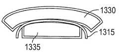
12A and 12B are views illustrating embodiments of attaching a membrane to a support;
13A to 13D are views illustrating embodiments of attaching a membrane to a support;
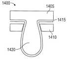
14A and 14B are views illustrating embodiments of attaching a membrane to a support;
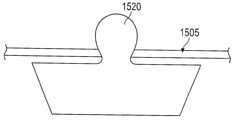
15A and 15B are views showing embodiments of attaching a membrane to a support;
16 is a perspective view of one embodiment of attaching a membrane to a support;
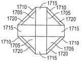
17 is a view showing an embodiment of managing a membrane sag (membrane sag).
18A and 18B show one embodiment of a suture delivery device handle.
19A and 19B show one embodiment of a suture delivery device handle;
20A-20C illustrate one embodiment of a suture catcher.
21A-21E illustrate embodiments of a multipurpose suture catcher.
22A-22D illustrate embodiments of a suture passer tip.
23A and 23B show one embodiment of a suture delivery device.
24A-24E illustrate embodiments of a suture catcher.
25A and 25B show one embodiment of a suture catcher.
26 shows an embodiment of a suture catcher.
27 shows an embodiment of a suture catcher.
서두에서, 본원은 특정 예시된 재료에 국한되지 않으며, 이러한 아키텍처, 루틴, 방법 또는 구조들은 변화될 수 있다는 것을 이해해야 한다. 따라서, 비록 본원에 기술된 것과 유사한 또는 동등한 다수의 이러한 선택사항은 본원의 실행 또는 실시예들에서 사용될 수 있고, 양호한 재료 및 방법들이 본원에 기재된다.At the outset, it is to be understood that this disclosure is not limited to the particular illustrated material, and that such architectures, routines, methods, or structures may vary. Accordingly, although many such options similar or equivalent to those described herein can be used in the practice or embodiments herein, the preferred materials and methods are described herein.
또한, 본원에 사용된 용어는 단지 본원의 특정 실시예를 기술할 목적인 것으로서 제한적으로 의도된 것이 아님을 이해해야 한다.It is also to be understood that the terminology used herein is for the purpose of describing particular embodiments herein only and is not intended to be limiting.
첨부된 도면과 연계하여 하기에 기술된 상세한 설명은 본원의 예시적 실시예들의 설명으로서 의도된 것이고 본원이 실시될 수 있는 단지 예시적 실시예를 나타내는 것으로 의도된 것은 아니다. 본 설명을 통해서 사용된 용어 "예시적"은 예, 보기, 예시를 의미하는 것이며 반드시 다른 예시적 실시예들에 대한 양호하거나 또는 유리한 것으로서 해석되지 않아야 한다. 상세한 설명은 명세서의 예시적 실시예들의 철저한 이해를 제공하기 위한 특정 상세설명을 포함한다. 본원의 예시적 실시예들은 이들 특정 상세 설명없이 실시될 수 있다는 것은 당업자에게 자명한 사실이다. 임의의 예들에서, 널리 공지된 구조 및 장치들은 본원에 제공된 예시적 실시예들의 불명료한 독창성을 회피하기 위하여 블록 형태로 도시된다.DETAILED DESCRIPTION The detailed description set forth below in connection with the appended drawings is intended as a description of exemplary embodiments herein and is not intended to represent merely exemplary embodiments in which the disclosure may be practiced. The term “exemplary” as used throughout this description means an example, example, example, and should not necessarily be construed as preferred or advantageous over other exemplary embodiments. The detailed description includes specific details for the purpose of providing a thorough understanding of the exemplary embodiments of the specification. It will be apparent to those skilled in the art that the exemplary embodiments herein may be practiced without these specific details. In some instances, well-known structures and devices are shown in block form in order to avoid obscuring the originality of the exemplary embodiments provided herein.
단지 편리성 및 명료성의 목적을 위하여, 방향성 용어, 예를 들어, 상단, 하단, 좌측, 우측, 상향, 하향, 위, 밑에, 아래, 뒤, 후방 및 전방은 첨부된 도면에 대해서 사용될 수 있다. 이들 및 유사 방향성 용어는 본원의 범주를 임의의 방식으로 제한하는 것으로 해석되지 않아야 한다.For purposes of convenience and clarity only, directional terms such as top, bottom, left, right, upward, downward, top, bottom, bottom, back, rear and front may be used with respect to the accompanying drawings. These and similar directional terms should not be construed as limiting the scope of the present application in any way.
다르게 규정하지 않는다면, 본원에 사용된 모든 기술적 및 과학적 용어들은 본원이 속하는 분야의 숙련된 기술자에 의해서 공통적으로 이해되는 것과 동일 의미를 가진다. 예를 들어, 용어 "봉합"은 천공부, 개방부 또는 다른 창상부를 폐쇄하기 위하여 가요성 재료와 함께 2개의 표면 또는 에지들을 당기는 것을 포함하고, 봉합사는 중합체, 거트, 금속 와이어 또는 다른 적당한 동등물과 같은 합성 또는 천연 재료이다.Unless defined otherwise, all technical and scientific terms used herein have the same meaning as commonly understood by one of ordinary skill in the art to which this application belongs. For example, the term “suturing” includes pulling two surfaces or edges together with a flexible material to close a perforation, opening, or other wound, wherein the suture is a polymer, gut, metal wire or other suitable equivalent. such as synthetic or natural materials.
본 명세서 및 첨부된 청구범위에 사용되는 바와 같이, 단일 형태의 용어들(a,an,the)은 내용을 명확하게 다르게 기술하지 않는다면 복수 용어를 포함할 수 있다.As used in this specification and the appended claims, terms in a single form (a, an, the) may include plural terms unless the content clearly dictates otherwise.
실시예들은 복강경 수술과 같은 수술 절차를 수행하는데 사용된 동일 개방부 안으로 삽입될 수 있는 봉합사 전달 장치에 대해서 기술하고 있다. 상기 봉합사 전달 장치는 주위 조직을 압축함으로써 개방부에 대한 기울어짐, 회전 또는 활주에 대한 가능성을 감소시킴으로써 개방부 내에서 장치를 안정시킨다. 따라서, 안정된 상기 봉합사 전달 장치는 봉합사를 소정 조직 영역 또는 층으로 신뢰성있게 지향시킴으로써 조직 물림성을 개선할 수 있다. 상기 봉합사 전달 장치는 포트 사이트 조직을 관통하고 관통후에 봉합사를 해제하기 위하여 전달 장치의 몸체를 통과하는 하나 이상의 봉합사 패서들을 배향시키는데 사용될 수 있다. 봉합사 전달 장치는 전달 장치를 후퇴시킬 때 봉합사를 포획하고, 상기 봉합사 단부들은 봉합사가 고정되고 개방부가 폐쇄되도록 개방부를 통해서 뒤로 당겨진다. 실시예들은 사용하기에 용이하고, 이는 길고 지루한 수술 절차에서 최종 단계일 수 있는 조직 폐쇄 장치에 대해서 중요하다.Embodiments describe a suture delivery device that can be inserted into the same opening used to perform a surgical procedure, such as laparoscopic surgery. The suture delivery device stabilizes the device within the opening by compressing the surrounding tissue, thereby reducing the potential for tilting, rotation, or sliding relative to the opening. Thus, the stable suture delivery device can improve tissue biteability by reliably directing the suture to a desired tissue area or layer. The suture delivery device may be used to orient one or more suture passers through the body of the delivery device to penetrate the port site tissue and release the suture after penetration. The suture delivery device captures the suture when retracting the delivery device, and the suture ends are pulled back through the opening such that the suture is secured and the opening is closed. The embodiments are easy to use, which is important for a tissue closure device that can be the final step in a long and tedious surgical procedure.
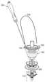
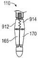
봉합사 전달 장치[또는 "창상 폐쇄 장치" 또는 "투관침 창상 폐쇄 장치(trocar wound closure device" (TWC)]는 일반적으로 2개의 부분들: 핸들(100) (도 1a, 도 1b) 및 봉합사 패서(도 2a 내지 도 2c)를 가진다. 도 1a 및 도 1b는 봉합사 전달 장치 핸들(100)의 일 실시예의 2개의 구성을 도시한다. 도 1a의 구성은 장치가 개방부 안으로 삽입될 때 사용된다. 도 1a에서, 핸들(100)은 비압축 구성이다. 도 1a는 샤프트(105),, 캐처(110)[캐처 요소(112,114)를 포함], 슬라이더(115), 바늘 트랙(150,155) 및 봉합사 출구 슬릿(160)을 갖는 핸들(100)을 도시한다. 샤프트(105)는 릿지 트랙(120)이 설치된 세장형 전개 부재이다. 슬라이더(115)는 원위 단부(135)를 향하여 샤프트(105)를 따라 이동할 수 있고 트랙(120)과 결합함으로써 제위치에 고정될 수 있는 압축 부재이다. 트랙(120)을 따른 미도시의 회전방지 범프들은 슬라이더(115)가 바늘 트랙(150,155)(도 1b)에 대해서 회전하는 것을 방지한다. 슬라이더 버튼(125)은 트랙(120)과 결합 또는 분리하는데 사용될 수 있다. 폐쇄된 것으로 도시된 캐처(110)는 전개될 때의 저항력 부재이고 폐쇄되고 봉합사를 파지할 수 있는 치형체(140)를 포함할 수 있다. 눌려진 것으로 도시된 제어 버튼(130)은 제어 로드(145)(도 1b)를 이동시키고, 이는 지지대(165,170)를 이동시킴으로써 캐처(110)를 개방(또는 전개) 또는 폐쇄한다. 캐처(110)가 폐쇄된 상태에서, 캐처(110) 및 샤프트(105)는 캐처(110)가 개방부를 통과할 때까지 수술 개방부 안으로 삽입될 수 있고, 개방 지점에서 캐처(110)는 도 1b에 도시된 바와 같이 전개될 수 있다.A suture delivery device (or “wound closure device” or “trocar wound closure device” (TWC)) generally has two parts: a handle 100 ( FIGS. 1A and 1B ) and a suture passer ( FIG. 1A , 1B ). 2A-2C) Figures 1A and 1B show two configurations of one embodiment of a suture
도 1b에서, 핸들(100)은 제어 버튼(130)이 해제되고, 제어 로드(145)가 보여지며, 캐처(110)가 전개되고 슬라이더(115)가 원위로 이동한 상태에서 압축 구성에 있다. 캐처(110)를 전개하기 위하여, 제어 버튼(130)은 제어 로드(145)를 근위로(즉, 제어 버튼(130)을 향하여 또는 이 도면에서 "위"로) 이동시켜서 지지대들(165,170)이 캐처(110)를 전개시키게 유도하도록 해제된다. 슬라이더(115)를 근위로 또는 원위로 이동시키기 위하여, 슬라이더 버튼(125)은 슬라이더(115)를 트랙(120)으로부터 분리시키는데 사용되고 그 다음 슬라이더(115)는 이동할 수 있다. 선택적으로, 슬라이더(115)는 샤프트(105)를 따라서 원위로 래칫될 수 있고, 슬라이더 버튼(125)은 슬라이더(115)를 트랙(120)으로부터 분리시키고 슬라이더(115)를 근위로 이동시키는데 사용된다(도 7 참조).In FIG. 1B , handle 100 is in a compressed configuration with
도 1b의 구성은 슬라이더(115) 및 캐처(110) 사이의 조직을 압축시킬 수 있다. 예를 들어, 근막, 근육 및 복벽의 복막층은 슬라이더(115) 및 캐처(110) 사이에서 압축될 수 있고, 복막은 캐처(110)에 최인접하다. 전개 상태로 도시된 바와 같이, 캐처(110)는 복벽의 개방부를 통해서 당겨지는 것에 저항한다. 따라서, 본 실시예에서, 캐처(110)는 저항력 부재이다. 다른 실시예에서, 저항력은 봉합사 포획 능력이 부족한 요소들에 의해서 인가될 수 있다. 유사하게, 다른 실시예에서, 봉합사 포획 능력은 저항력이 부족한 요소들에 의해서 제공될 수 있다.The configuration of FIG. 1B may compress the tissue between the
본 구성에서, 슬라이더(115) 및 캐처(110) 사이에서 조직이 압축된 상태에서, 핸들(100)은 압축 조직에 대해서 안정되어서, 회전, 활주 및 기울어짐에 대한 가능성을 감소시킨다. 더우기, 핸들(100)이 안정된 상태에서, 바늘 트랙(150,155)은 또한 봉합될 조직인 주위 조직에 대해서 안정된다. 이는 봉합사의 최적의 배치 및 봉합사를 재생 방식으로 전개하는 것을 제공하고, 이들의 양자 모두는 적당한 조직의 물림을 보장하고 수술자에게 필요한 숙련도의 양을 최소화하도록 작용한다.In this configuration, with the tissue compressed between the
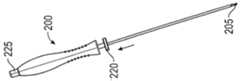
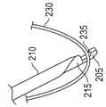
도 2a 내지 도 2c는 봉합사 패서(200)의 일 실시예를 도시하고, 봉합사 패서(200)는 봉합사를 파지하고 봉합사를 바늘 트랙, 예를 들어 바늘 트랙(150)을 통과하여 봉합사가 캐처(110)에 의해서 포획될 수 있게 봉합사를 배치하는데 사용된다. 봉합사 패서(200)는 원위 단부에 있는 후크(205), 바늘 튜브(210), 샤프트(215), 트리거(220) 및 바늘 버튼(225)을 포함한다. 후크(205)는 샤프트(215)의 원위 단부에 있다. 바늘 튜브(210)는 원위 단부에 첨부를 가지며 후크(205)을 커버하거나 또는 커버하지 않기 위해 샤프트(215)에 대해서 이동할 수 있다. 후크(205)는 봉합사(230)(도 2b 참조)를 수용하도록 구성되고, 바늘 튜브(210)에 의해서 커버될 때, 봉합사를 보유한다(도 2c 참조). 후크(205)는 봉합사를 적재하는 동안 필요하지 않은 무딘 팁 - 첨부를 가질 수 있다. 후크(205)는 또한 후크(205)가 커버되지 않을 때 봉합사가 활주할 수 있게 하는 경사로(235)를 가질 수 있다. 도 2a에서, 바늘 버튼(225)은 연장(비가압) 상태로 도시되고 후크(205)는 커버되지 않은 상태로 도시된다. 바늘 버튼(225)은 눌려질 때 봉합사를 보유하기 위해 후크(205)에 대해서 바늘 튜브(210)를 연장시킬 수 있다. 트리거(220)는 눌려질 때 봉합사를 해제하기 위하여 결과적으로 바늘 튜브가 후크(205)를 커버되지 않은 상태가 되게 한다. 바늘 튜브(210), 샤프트(215), 후크(205) 및 트리거(220)는 바늘 트랙(150,155) 내에 끼워지고 전개된 캐처(110)에 대해서 원하는 위치에서 봉합사를 전달 및 해제하도록 구성된다.2A-2C show one embodiment of a
도 2b 및 도 2c는 일반적으로 봉합사 패서(200)의 적재를 도시한다. 봉합사 패서(200)는 바늘 버튼(225) 및 트리거(220)에 의해서 제어되는 2개의 상태를 가진다. 초기 "오프" 상태에서, 샤프트(215) 및 후크(205)는 바늘 튜브(210)로부터 돌출한다. 후크(205)는 본 구성에서 봉합사를 수용하는데 사용된다. 즉, 봉합사(230)는 후크(205)에 의해서 붙잡혀지게 배치될 수 있다. "온" 상태로 전이되기 위하여, 사용자는 바늘 버튼(225)을 누르고, 이는 바늘 튜브(210)가 봉합사(230) 및 후크(205)를 커버하도록 연장되게 한다. 따라서, 샤프트(215), 후크(205) 및 바늘 튜브(210)는 봉합사(230)를 보유 또는 붙잡기 위해 협력한다. "오프" 상태로 복귀하기 위하여, 트리거(220)는 근위 방향으로 누름으로써 작동될 수 있다. 트리거(220)를 누르면, 그에 의해서 봉합사(230)를 해제할 수 있다.2B and 2C show the loading of the
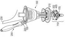
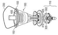
도 3은 봉합사 전달 장치(300)를 도시한다. 도 3에서, 봉합사 패서(200)는 핸들(100)의 바늘 트랙(150) 안으로 삽입된다. 핸들(100)은 캐처(110)가 전개되고 슬라이더(115)가 원위로 이동한 상태에서 압축 구성에 있다. 바늘 버튼(225)은 바늘 튜브(210)가 후크(205)를 커버하는 상태(미도시)에서 눌려지는 것으로 도시된다. 바늘 튜브(210)의 원위 팁은 멤브레인(302) 인근에 있다. 멤브레인(302)은 캐처 요소(114 및 314) 사이로 연장된다. 멤브레인(305)은 캐처 요소(112 및 312) 사이로 연장된다.3 shows a
도 3에 도시된 바와 같이, 바늘 트랙(150)은 전개된 캐처(110)의 캐처 요소들(114 및 314) 사이의 영역으로 향하게 봉합사 패서(200)를 배향시켰다. 본 실시예에서, 캐처(110)에서 그 영역에 멤브레인(302)이 제공되었다. 멤브레인(302)은 봉합사를 포획하기 위하여 캐처(110)의 기능을 개선하도록 부가된다. 봉합사 패서(200)가 바늘 트랙(150) 안으로 추가로 삽입되면, 바늘 튜브(210)의 예리한 첨부는 멤브레인(302)을 관통하고, 봉합사(미도시)를 그와 함께 운반한다. 추가 삽입은 트리거(220)가 바늘 트랙(150)의 개방부와 접촉하게 한다. 또한 추가 삽입은 트리거(220)가 작동하게 하고 바늘 튜브(210)가 후퇴하게 하여, 후크(205)를 노출시키고 봉합사(미도시)를 해제한다. 이 첨부에서, 봉합사 패서(200)는 바늘 트랙(150)으로부터 후퇴할 수 있다. 봉합사 패서(200)를 바늘 트랙으로부터 후퇴시키면 또한 이를 멤브레인(302)으로부터 후퇴시킨다. 그러나, 후크(205)로부터 방출된 봉합사는 멤브레인(302) 내에 보유된다. 그 다음, 캐처(110)가 후퇴하면, 멤브레인(302)도 역시 후퇴하여, 봉합사를 캐처 요소들(114,314)에 의해서 붙잡히게 한다. 이는 도 9a 및 도 9b에 대해서 추가로 기술된다.As shown in FIG. 3 , the
도 4a 내지 도 4c는 자동 봉합사 해제를 제공하는 핸들(100)의 일 실시예를 도시한다. 단일 봉합사의 2개의 단부들이 수술 개방부 안으로 전달되고 봉합사 전달 장치의 원위 단부에 보유될 때 근위 단부 부근의 봉합사 부분은 루프를 형성한다. 루프는 장치의 퇴거 중에 장치와 얽매일 수 있다. 기존의 폐쇄 장치는 수술자가 봉합사를 장치로부터 수동으로 분리될 수 있게 한다. 도 4a 내지 도 4c의 실시예는 봉합사(415)의 자동 해제를 용이하게 하는 내부 봉합사 탈출 슬롯(400)을 사용한다. 봉합사 탈출 슬롯(400)은 그 길이에 걸쳐 바늘 트랙(150,155)을 연결하여, 봉합사(415)가 핸들(100)을 통과하고 봉합사 출구 슬롯(160)을 빠져나오게 하는 슬롯을 제공한다. 도 4a에서, 봉합사 패서(200)는 바늘 트랙(155) 안에 삽입되고 샤프트(105)로부터 연장되어서 바늘 튜브(210)를 노출시킨다. 바늘 튜브(210)는 멤브레인(305)을 침투한 후의 상태로 도시된다. 봉합사(415)의 봉합사 팁(410)은 또한 멤브레인(305)을 통과하고, 봉합사 패서(200)의 팁에 의해서 운반된 상태로 도시된다. 제어 버튼(130)은 연장 상태로 도시된다. 따라서, 바늘 튜브(210)는 후크(205)를 커버하지 않고 봉합사 단부(410)는 [비록 바늘 팁은 멤브레인(305)에 의해서 도 4a에서 불명료하지만] 봉합사 패서(200)로부터 해제된다. 바늘 트랙(150)은 봉합사 단부(405)가 멤브레인(302)을 통과하고, 해제되며, 봉합사 패서(200)가 후퇴한 이후의 봉합사(415)를 나타낸다. 도 4a에 도시된 바와 같이, 양쪽의 봉합사 단부(405,410)는 멤브레인(302,305)에 의해서 보유된다. 봉합사 단부(405)로부터, 봉합사(415)는 바늘 트랙(150)을 통해서 상기 바늘 트랙으로부터 통과하고 핸들(100)에 걸쳐 루프를 만들고, 봉합사 패서(200)에 의해서 동반되고, 바늘 트랙(155)으로 진입한다. 도 4a 내지 도 4c에 있어서, 슬라이더(115)는 내부 봉합사 탈출 경로를 더욱 명확하게 설명하기 위해 도시되지 않는다.4A-4C show one embodiment of a
도 4b에 있어서, 봉합사 패서(200)는 바늘 트랙(155)으로부터 후퇴하고 캐처(110)는 철수하여, 봉합사 단부들(405,410)을 파지한다. 핸들(100)은 본 구성에서 수술 개방부로부터 후퇴하여, 봉합사 단부들(405,410)을 이에 의해 당긴다. 봉합사(415)는 바늘 트랙 출구(152) 및 캐처(110) 사이에 루프를 만든다. 봉합사(415)는 또한 바늘 트랙 출구(157) 및 캐처(110)에 루프를 만든다. 이들 루프들은 봉합될 조직을 통과한 봉합사(415)의 일부를 나타낸다. 따라서, 핸들(100)이 수술 개방부로부터 제거되고, 이에 의해서 봉합사 단부들(405,410)을 당길 때, 조직을 통과한 고리형 봉합사(415)의 섹션은 봉합사 탈출 슬롯(400)(점선으로 도시됨)을 통해서 봉합사(415)의 잔여부를 아래로 당길 것이다. 도 4c에서, 봉합사(415)는 봉합사 탈출 슬롯(400)을 통해서 봉합사 출구 슬롯(160)으로부터 완전히 통과하였다.In FIG. 4B , the
따라서, 도 1 내지 도 4에 있어서, 봉합사 전달 장치(300)의 핸들(100)의 실시예들은 바늘 트랙 요소들, 예를 들어, 바늘 트랙(150,155) 및 봉합사 보유 요소들 예를 들어, 캐처(110)를 포함할 수 있다. 바늘 트랙 요소들은 핸들(100)의 근위 단부로부터 원위 단부를 향하여 연장되고 자동 봉합사 해제 기구, 예를 들어, 봉합사 탈출 슬롯(400)을 포함할 수 있다. 봉합사 보유 요소는 핸들(100)의 원위 단부에 또는 인근에 배치될 수 있다. 봉합사 전달 장치는 또한 압축 요소 예를 들어, 슬라이더(115)를 가질 수 있다.Thus, with reference to Figures 1-4, embodiments of
바늘 트랙 요소들은 핸들[예를 들어, 핸들(100)]을 통해서 삽입된 바늘[예를 들어, 봉합사 패서(200)]에 대한 규정된 궤도를 제공하고, 근위 단부에서 시작하고 원위 단부 부근에서 나온다. 예를 들어, 핸들이 수술 개방부 안으로 삽입된 상태에서, 바늘은 피부 위에 있는 바늘 트랙 요소[예를 들어, 바늘 트랙(150)]의 근위 단부로 진입하고 장치에 있는 바늘 트랙을 통해서 이동하며 원위 단부를 빠져나와서 핸들에 대한 규정된 위치 및 각도에서 조직층[예를 들어, 근막, 근육 및 복막]을 통해서 침투한다. 바늘 궤도는 입구 및 출구 사이에서 핸들에 의해서 완전히 봉입될 수 있다. 바늘 트랙 요소는 자동 봉합사 해제 기구[도 4a 내지 도 4c를 참조하여 기술됨]와 결합됨으로써 봉합사 루프(또는 봉합사 단부를 배제하는 봉합사의 주요 섹션)는 장치의 원위 단부에 보유되지 않고 핸들이 수술 개방부로부터 후퇴할 때 사용자의 개입없이 바늘 트랙으로부터 활주할 수 있다.The needle track elements provide a defined trajectory for a needle (eg, suture passer 200) inserted through a handle (eg, handle 100), starting at the proximal end and exiting near the distal end. . For example, with the handle inserted into the surgical opening, the needle enters the proximal end of a needle track element over the skin (eg, needle track 150 ) and travels through the needle track in the device and distal It exits the end and penetrates through the tissue layers (eg, fascia, muscle, and peritoneum) at a defined location and angle relative to the handle. The needle track can be completely enclosed by the handle between the inlet and outlet. The needle track element engages an automatic suture release mechanism (described with reference to FIGS. 4A-4C ) such that the suture loop (or the major section of the suture excluding the suture end) is not retained at the distal end of the device and the handle is surgically opened. It can slide from the needle track without user intervention when retracting from the buoy.
봉합사 보유 요소[예를 들어, 캐처(110)]는 프레임[예를 들어, 캐처 요소들(112,114,312,314)] 및 봉합사 포획면(들)[예를 들어, 멤브레인(302,305)]을 포함하거나 또는 단지 프레임만 포함할 수 있다. 봉합사 보유 요소는 봉합사에서 파지기능을 개선하기 위해 형태부들[예를 들어, 치형체(140)]를 가질 수 있다. 봉합사 보유 요소 프레임은 다수의 지지대들을 가지며 여러 기하학적 형태들(예를 들어, 평탄, 랜턴, 몰리, 우산 등의 형태]을 가질 수 있다. 봉합사 보유 요소 프레임은 목표 영역을 형성하고 압축 요소의 압축력에 저항력을 제공하고 조직을 그 사이에 개재시킬 수 있다. 이 저항력은 예를 들어, 복막에 대한 것일 수 있다. 봉합사 보유 요소는 또한 바늘 삽입 중에 선택형 봉합사 포획 표면에 지지부를 제공할 수 있다. 봉합사 보유 요소는 낮은 프로파일 또는 후퇴 상태에서 조직 개방부를 통해서 삽입되고 조직층을 통해서 예를 들어, 복막강 내에 있는 의도한 위치로 통과한 후에 팽창 상태로 전개된다. 봉합사 포획 표면은 프레임의 지지대에 결합되고 장치 삽입 중에 뿐 아니라 장치 후퇴 중에 접힘 구성일 수 있다.The suture retention element (eg, catcher 110 ) includes a frame (eg,
봉합사 운반 바늘[예를 들어, 봉합사 패서(200)]은 바늘 트랙 요소[예를 들어, 바늘 트랙(150)] 안으로 도입되고, 조직층을 침투[예를 들어, 복막을 통과]하도록 안내되고 캐처 안으로 삽입될 수 있다[예를 들어, 캐처 요소(112,312) 사이에 배치되거나 또는 멤브레인(305) 안으로 삽입될 수 있다]. 바늘의 원위 팁의 디자인은 봉합사가 바늘로부터 분리되게 허용할 수 있다[예를 들어, 후크(205)는 봉합사(230)가 활주할 수 있게 하는 경사로(235)를 가질 수 있다]. 임의의 실시예에 있어서, 바늘은 바늘이 의도한 위치 안으로 삽입될 때 봉합사가 팁으로부터 방출되도록 유발될 수 있다.A suture delivery needle (eg, suture passer 200 ) is introduced into a needle track element (eg, needle track 150 ), guided to penetrate a tissue layer (eg, through the peritoneum) and into the catcher may be inserted (eg, disposed between
임의의 실시예에 있어서, 바늘 팁 디자인[예를 들어, 경사로(235)]은 봉합사가 바늘로부터 분리될 수 있게 한다. 포획 표면[예를 들어, 멤브레인(302,305)]을 갖는 실시예에 있어서, 상기 표면은 자체적으로 표면에 의해서 봉합사의 보유 및 포획을 개선하는 디자인 또는 특성을 가질 수 있으며, 이는 봉합사가 바늘로부터 분리되는 것을 보조한다.In certain embodiments, the needle tip design (eg, ramp 235) allows the suture to be disengaged from the needle. In embodiments having a capture surface (eg,
장치는 (예를 들어, 캐처에 있는) 장치의 원위 단부에서 포획된 봉합사 단부들을 보유하는 동안, 수술 개방부(예를 들어, 투관침 창상)로부터 후퇴할 수 있다.The device may be withdrawn from the surgical opening (eg, trocar wound) while retaining the captured suture ends at the distal end of the device (eg, in the catcher).
일 실시예에 있어서, 멤브레인은 본질적으로 조직층을 통한 캐처의 삽입 및 후퇴 중에 캐처 프레임에 의해서 봉입된다. 실시예들에 있어서, 상기 봉합사 단부들은 멤브레인에 포획될 뿐 아니라 폐쇄된 캐처 프레임의 지지대들 사이에서 유지될 수 있다. 봉합사 보유 요소가 프레임을 포함하는 실시예에 있어서, 봉합사 단부들은 장치 퇴거 중에 폐쇄 프레임의 지지대들 사이에서 기계적 체결에 의해서 보유될 수 있다.In one embodiment, the membrane is essentially encapsulated by the catcher frame during insertion and retraction of the catcher through the tissue layer. In embodiments, the suture ends may be captured by the membrane as well as held between supports of a closed catcher frame. In embodiments where the suture retaining element comprises a frame, the suture ends may be retained by mechanical engagement between supports of the closure frame during device withdrawal.
봉합사 전달 장치는 또한 압축 요소, 예를 들어 구조를 변화시키기에 적합하도록 장치 샤프트를 따라서 이동할 수 있는 슬라이더(115)를 가질 수 있다. 압축 요소는 저항력 부재[예를 들어, 캐처(110)]를 향하여 조직을 개재하는 위치에 배치될 수 있다. 예를 들어, 조직은 복벽의 층들일 수 있고, 상기 저항력 부재는 복막에 대해서 복막강에 배치될 수 있으며, 압축 요소는 피부 표면에 대해서 배치될 수 있다. 압축 요소는 그에 의해서 가변 구조에 적합하게 되면서 조직을 안정시킨다. 임의의 실시예에 있어서, 압축 요소는 압축 요소의 이동이 저항력 부재가 전개 및 후퇴되게 하도록 저항력 부재 전개 기구에 연동될 수 있다.The suture delivery device may also have a compression element, eg, a
도 5a 및 도 5b는 신축식 바늘 트랙(153,158)을 갖는 핸들(100)의 일 실시예의 단면을 도시한다. 도 5a에서, 핸들(100)은 비압축 구성에서 슬라이더(115)는 캐처(110)로부터 멀리 근위로 연장된다. 단순성을 위하여, 신축식 바늘 트랙(153,158)은 유사하기 때문에, 단지 신축식 바늘 트랙(153) 만이 기술될 것이다. 신축식 바늘 트랙(153)은 튜브(505) 내에서 튜브(510)를 신축시키도록 구성된 한 쌍의 튜브들(505,510)을 포함한다. 일 실시예(미도시)에서, 튜브(505)는 튜브(510) 내에서 이동하여, 봉합사 패서는 삽입될 때 튜브(510)의 단부를 타격하는 것을 회피한다. 도 5a 및 도 5b에 있어서, 튜브(505)는 비신축식 단부에서 슬라이더(115)에 고정된다. 튜브(510)는 비신축식 단부에서 샤프트(105)에 고정된다. 앵커 부착부는 튜브 및 고정 지점 사이에서 각도 움직임을 허용한다. 도 5b에 있어서, 핸들(100)은 슬라이더(115)가 캐처(110)를 향하여 원위로 이동하는 상태의 압축 구성에 있다. 이 움직임에 의해서, 신축식 바늘 트랙들(153,158)은 길이가 짧아지고 이들이 핸들(100)을 나오는 각도를 변경하였다. 아직, 신축식 바늘 트랙(153,158)은 봉합사 패서를 캐처(110)를 향하여 지향시키도록 배향된다. 비압축 구성에서 압축 구성으로 슬라이더(115)가 이동할 때, 신축식 바늘 트랙(153)은 상부 한계(520), 하부 한계(525) 및 바늘 트랙 출구(12)에 의해서 한정되는 샤프트(105) 내의 용적부를 제거하였다. 본 실시예에서, 핸들(100), 샤프트(105) 및 슬라이더(115)는 신축식 바늘 트랙(153,158)의 이러한 움직임을 허용하도록 구성된다.5A and 5B show cross-sections of one embodiment of a
실시예를 사용하는 방법에 있어서, 핸들(100)은 초기에 비압축 및 후퇴 구성에 있다. 제 1 단계에서, 핸들(100)은 투관침 창상 안으로 삽입된다. 다음 단계에서, 제어 버튼(130)은 눌려져서 캐처(110)를 개방시킨다. 다음 단계에서, 핸들(100)은 캐처(110)가 복막과 접촉할 때까지 조직을 향하여 당겨진다. 다음 단계에서, 슬라이더(115)는 아래로 눌려저서 복벽을 캐처(110)에 대해서 개재시킨다. 핸들은 그 다음 봉합될 조직 내에서 안정된다. 다음 단계에서, 봉합사(230)의 일 단부는 후크(205) 상에 적재되고 바늘 버튼(225)은 눌려진다. 다음 단계에서, 봉합사 패서(200)는 바늘 트랙 안으로 삽입되고 트리거(220)는 작동되어서, 봉합사(230)를 해제시킨다. 다음 단계에서, 봉합사 패서(200)는 핸들(100)로부터 후퇴된다. 다음 단계에서, 봉합사(230)의 제 2 단부(또는 상이한 봉합사의 단부)는 후크(205) 상으로 적재되고 이전 2개의 봉합사 통과 단계는 상이한 바늘 트랙에서 반복된다. 핸들(100)은 이제 후퇴되어서 차후 단계에 따라서 봉합사 단부들을 취한다. 다음 단계에서, 제어 버튼(130)은 눌려져서 봉합사 단부들을 캐처(110)에 의해서 포획한다(봉합사 단부들은 또한 선택형 멤브레인(302,305)에 의해서 보유되었다. 다음 단계에서, 핸들(100)은 수술 개방부에서 후퇴하여, 봉합사 단부들을 이동시킨다. 봉합사 단부들은 그때 핸들(100)로부터 제거되고 매듭지워진다.In the method of using the embodiment, the
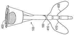
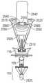
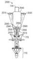
도 6a 내지 도 6c는 후퇴하고 부분 전개되고 그리고 완전 전개된 구성에 있는 봉합사 캐처(110)의 일 실시예를 도시한다. 도 6a에 있어서, 봉합사 캐처(110)는 힌지 조인트(705,710,715), 지지대(165,170) 및 캐처 요소(112,114)를 가진다. 조인트(705,710,715)는 기계식 또는 활동 힌지 또는 조합물일 수 있다. 도 6b에 있어서, 캐처(110)는 캐처 요소들(300)를 향하여 지지대(165,170)를 가압하기 위하여 제어 로드(145)를 사용하여 부분 전개 상태로 확장되었다. 캐처 요소(312,314)는 유사하게 전개되었다. 도 6c에서, 캐처(110)는 제어 로드(145)를 사용하여 완전 전개되었다. 도 6c는 또한 캐처 요소(112,114)에 부착된 선택형 멤브레인(302,305)을 도시한다. 제어 버튼(130)(도 1 및 도 3)은 제어 로드(145)에 연결되고 제어 로드(145)를 작동시키기 위해 사용될 수 있다.6A-6C show one embodiment of the
도 7은 핸들(100)의 일 실시예의 섹션을 단면도로 도시한다. 도 7의 실시예에서, 슬라이더(115)는 원위 방향을 향하여 그러나 근위 방향을 향하지 않고 래칫(805) 및 랙(810)을 사용하여 용이하게 이동할 수 있다. 따라서, 슬라이더(115)는 압축 구성을 향하여 그러나 비압축 구성을 향하지 않고 용이하게 이동할 수 있다. 실시예에서, 슬라이더 버튼(125)을 눌러서 래칫(805)을 해제하여, 슬라이더(115)가 근위로 이동할 수 있게 허용한다. 랙(810)은 슬라이더가 압축 방향으로 과도하게 이동하는 것을 방지하는 하부 한계(미도시)를 포함한다. 일 실시예에서, 마찰 패드(미도시)는 슬라이더(115) 및 샤프트(105) 사이에서 사용된다. 마찰 패드의 형상은 2개의 방향으로 누름 마찰을 조절하도록 설계된다.7 shows, in cross-section, a section of one embodiment of
도 8a 내지 도 8g는 봉합사를 전개하는 여러 스테이지들에서의 일 실시예를 도시한다. 도 8a는 바늘 트랙(150) 안으로 삽입된 적재된 봉합사 패서(200)의 사시도이다. 도 8a에서, 캐처(110)는 전개 구성에 있다. 봉합사 단부(405)를 파지하는 바늘 튜브(210)는 바늘 트랙(150)을 나오지만 아직 멤브레인(302)을 침투하지 않았다. 도 8b에서, 봉합사 패서(200)는 바늘 튜브(210)가 멤브레인(302)(미도시)을 침투하여 봉합사 단부(405)를 마찬가지로 멤브레인(302)을 통과시키도록 바늘 트랙(150) 안으로 추가로 삽입되었다. 도 8b에서, 바늘 튜브(210)는 조직(902,904,906)의 3개 층들을 침투하는 것으로 도시된다. 따라서, 결국에는, 봉합사(230)의 물림은 이들 층들을 포함할 것이다. 도 8c에서, 봉합사 패서(200)는 바늘 트랙(150) 안으로 추가로 삽입되어서, 트리거(220)가 눌려지게 하고, 이는 도 2a 내지 도 2c에 대해서 기술된 바와 같이 바늘 튜브(210)를 "오프"시키도록 리셋되고 봉합사 패서(200)로부터 봉합사(230)를 해제시킨다. 도 8d는 도 8c로부터 장치의 폐쇄를 도시한다. 도 8d에서, 바늘 튜브(210) 및 봉합사 단부(405)는 멤브레인(302)을 침투하였다. 봉합사 단부(405)는 후크(205) 및 바늘 튜브(210)가 없는 것으로 도시된다. 도 8e에서, 봉합사 패서(200)는 바늘 트랙(150)으로부터 후퇴되었다. 봉합사 단부(405)는 멤브레인(302)의 보유 압착 특성에 의해서 보유 - 유지되었다. 도 8f는 봉합사 단부(415), 바늘 트랙(155) 및 멤브레인(305)(미도시)에 의해서 반복된 프로세스를 도시한다. 도 8f는 또한 조직층(902, 904, 906)을 각각 통과한 봉합사 단부(405,410)에서의 봉합사의 물림을 도시한다. 도 8g는 봉합사 패서(200)가 봉합사 단부(405,410)를 멤브레인(302,305) 안으로 각각 전개시키고 후퇴시킨 후의 핸들(100)을 도시한다.8A-8G show one embodiment at various stages of deploying the suture. 8A is a perspective view of a loaded
도 9a 및 도 9b는 봉합사 단부를 포획하는 상이한 스테이지들의 핸들(100)을 도시한다. 봉합사 단부(405,410)가 멤브레인(302,305)으로 전개된 후에(도 8g와 같이), 제어 버튼(130)은 눌려져서, 제어 로드(145)를 원위로 이동시켜서 캐처(110)를 폐쇄한다. 도 9a는 봉합사 단부를 포획하는 프로세스를 통해서 대략 중간에 있는 핸들(100)을 도시한다. 제어 버튼(130)이 눌려질 때, 멤브레인(302,305)은 캐처 요소[114,314(도 3) 및 112,312(도 3)] 사이에서 각각 접혀져서, 이들에 의해서 봉합사 단부(405,410)를 이동시킨다. 도 9b는 후퇴 구성에 있는 캐처(110)를 도시한다. 제어 버튼(130)은 완전히 눌려졌다. 이 구성에서, 캐처(110)는 아직 압축 위치에 있는, 슬라이더(115)의 압축력에 대한 저항력을 더이상 제공하지 않는다. 즉, 캐처(110)는 더이상 조직층(902,904,906)에 평탄 표면을 제공하지 않으며 용이하게 후퇴할 수 있다. 완전 후퇴 위치에서, 요소(114,314 및 112,312)는 각각의 봉합사 단부(405,410)를 체결한다. 또한 요소들(114,314 및 112,312)(도 6c, 도 8d 참조) 사이에 있는 선택형 치형체(140)는 봉합사 단부(405,410)에서의 유지력을 개선한다.9A and 9B show the
도 10a 및 도 10b는 캐처(110)가 완전히 후퇴한 이후에 봉합사를 자동으로 해제하는 핸들(100)의 일 실시예를 도시한다. 도 10a에서, 봉합사(230)는 핸들(100) 상의 캐처(110)에 의해서 포획된 봉합사 단부(405,410)를 갖는, 예를 들어 복벽의 층(902,904,906) 상으로 전개되었다. 핸들(100)은 수술 개방부(1100)로부터 당겨져서, 핸들에 의해서 봉합사 단부(405,410)를 운반하고 봉합사(230)를 수술 개방부(1100) 안으로 그리고 조직층(902,904,906)을 통해서 당긴다. 이는 봉합사 탈출 슬롯(400)(도 4a 내지 도 4c 참조)으로 진입하기 위하여 봉합사(230)의 루프를 유도한다. 도 10b에서, 핸들에서의 지속된 당김은 봉합사(230)의 잔여부가 봉합사 탈출 슬롯(400)을 통해서 그리고 봉합사 출구 슬롯(160)으로부터 외부로 통과하게 한다.10A and 10B show one embodiment of a
창상을 폐쇄하는 실시예를 사용하는 방법은 비압축 및 후퇴 구성에서 봉합사 전달 장치 핸들 및 핸들로부터 분리된 봉합사 패서로 개시된다. 단계 1에서, 한 손은 창상으로부터 투관침을 제거한다. 단계 2에서, 다른 손은 캐처가 복강경 이미지에서 완전히 보여질 때까지 투관침 창상 안으로 핸들을 삽입한다. 단계 3에서, 한 손가락은 복강경 이미지를 사용하여 시각적 안내 하에서 캐처를 개방하기 위하여 제어 버튼을 누른다. 단계 4에서, 한 손은 핸들을 잡고 다른 손은 봉합될 조직이 슬라이더와 캐처 사이에서 확고하게 개재될 때까지 슬라이더를 환자를 향하여 밀어낸다. 복강경 이미지는 캐처가 복막벽과 접촉하는지를 나타내는데 사용될 수 있다. 단계 5에서, 한 손은 봉합사 패서 몸체를 잡고 다른 손은 봉합사의 일 단부를 봉합사 패서의 후크 안으로 밀어낸다. 손가락은 그 다음 봉합사 패서를 적재하기 위하여 바늘 버튼을 누른다. 단계 6에서, 한 손은 핸들을 잡고 다른 손은 트리거가 작동하여, 다시 복강경 이미지의 시각적 안내 하에서 캐처에서 봉합사를 해제(또는 전개)할 때까지 바늘 트랙을 통해서 봉합사 패서를 삽입한다. 단계 7에서, 단계 5 및 6은 봉합사의 다른 단부 및 다른 바늘 트랙으로 반복된다. 단계 8에서, 하나의 손가락은 시각적 안내 하에서 봉합사 단부들을 포획하기 위하여 제어 버튼을 누른다. 단계 9에서, 한 손은 창상으로부터 핸들을 당기고 이로부터 2개의 봉합사 단부들을 받아들인다.A method of using an embodiment to close a wound is disclosed with a suture delivery device handle in an uncompressed and retracted configuration and a suture passer separate from the handle. In step 1, one hand removes the trocar from the wound. In
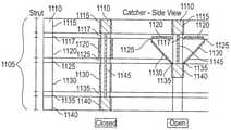
도 11은 개방 및 폐쇄 봉합사 캐처 구조체의 일부로서 평면도 및 단면도로 봉합사 캐처 구조체로부터의 지지대들의 일 실시예를 도시한다. 봉합사 캐처(1105)는 다수의 지지대(1110)를 수용할 수 있다. 각각의 지지대(1110)는 근위 조인트(상부 힌지)에 대한 근위 연결 부분(1115), 상부 지지대(1120), 중간 힌지(1125), 하부 지지대(1130), 원위(또는 하부) 힌지(1135) 및 원위 힌지(1135)에 대한 원위 연결 부분(1140)을 가질 수 있다. 힌지들은 활성 힌지, 기계식 힌지 또는 금속 와이어/플레이트 스프링 힌지일 수 있다. 지지대들은 금속(즉, 스테인레스 강), 플라스틱(즉, 플리프로필렌, 폴리카보네이트, 폴리우레탄, 나일론 또는 폴리에틸렌) 또는 임의의 다른 적당한 재료로 제조될 수 있다. 다수의 지지대들은 캐처를 형성하기 위하여 근위 조인트 뿐 아니라 원위 조인트에서 연동될 수 있다. 제어 로드(1145)는 캐처의 원위 연결 부분(1140)에 결합될 수 있고 봉합사 전달 장치의 근위 단부로 연장될 수 있다. 일 실시예에서, 제어 로드(1145)의 움짐임은 원위 연결 부분(1140)의 상하 이동을 구동하여, 결과적으로 봉합사 캐처를 개방(원위 상부 연결 또는 "전개") 또는 폐쇄(원위 하부 연결 또는 "후퇴")시킨다. 대안 실시예에서, 캐처 전개 기구는 근위 연결 부분(1115)을 제어함으로써 구동될 수 있다. 실시예에서, 전개 구성에 있을 때 캐처(1105)는 조직 압축력에 대한 저항력 부재로서 작용한다.11 shows one embodiment of supports from a suture catcher structure in top and cross-sectional views as part of an open and closed suture catcher structure.
하부 및 상부 지지대의 길이는 캐처(1105)의 원하는 길이 또는 상부 및 하부 지지대 사이의 원하는 각도에 기초하거나 또는 양자 모두에 기초하여 선택될 수 있다. 지지대들의 형상은 직사각형 또는 사다리꼴일 수 있다. 직사각형에 대한 사다리꼴 형상의 장점은 사다리꼴 형상이 추가 멤브레인 팩킹 공간을 제공한다는 것이다. 지지대들의 외면(후퇴한 구성에서 보이는 표면)은 평탄함, 곡선형 에지를 갖는 평탄함 또는 곡선형을 포함하는 많은 가능한 변형들을 가진다. 곡선형 표면들을 갖는 디자인은 결과적으로 예리한 에지들이 더욱 적기 때문에 더욱 비외상성 외부 프로파일을 갖는 봉합사 전달 장치가 얻어질 수 있다. 즉, 여러 실시예들에서, 지지대 구성요소들(돌출 및 정합 형태부들을 포함)은 더욱 둥근 외부 프로파일을 생성하도록 곡선형일 수 있다(예를 들어, 도 13c 참조).The length of the lower and upper supports may be selected based on the desired length of the
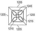
도 12a 및 도 12b는 멤브레인(1200)을 지지대(1205)에 부착하는 일 실시예를 도시한다. 멤브레인(1200)은 폴리우레탄, PVC, 폴리프로필렌 또는 천공되거나 또는 접혀지는 것에 대해서 너무 과도하게 저항하지 않는 다른 순응성 재료와 같은 재료로 제조될 수 있다. 장치 후퇴 중에 지지대들 사이에 더욱 신뢰성있게 봉합사를 보유하기 위하여, 캐처는 인접 지지대들(또는 치형체와 같이 봉합사를 고정하기 위한 형태부들)이 설계 방식으로 결합할 수 있도록 폐쇄되어야 한다. 캐처의 적당한 폐쇄는 멤브레인이 캐처 프레임 폐쇄체와 간섭하지 않는 프로파일로 접혀저셔 팩킹되면 더욱 많이 발생할 수 있다. 그러나, 캐처 멤브레인은 임의의 특정 방향 또는 구성으로 자연적으로 접혀지거나 또는 팩킹되지 않는다. 또한, 멤브레인이 팩킹될 수 있는 공간은 지지대들이 수축될 때 지지대들에 의해서 봉입되는 공간이고, 상기 공간은 제한된다. 더우기, 가변 두께 및 강성도를 갖는 멤브레인은 상이한 접힘 거동을 가진다. 지지대에 대한 멤브레인 부착 위치는 접힘 거동에 영향을 주는 것으로 확인되었다. 따라서, 실시예들에서, 캐처의 지지대 또는 프레임은 원하는 방식으로, 예를 들어, 원하는 방식으로 제어 로드(1245)를 향하여 방사상 내향으로 접혀지기 위하여 멤브레인을 안내하도록 설계될 수 있다(도 12b).12A and 12B show one embodiment of attaching a
멤브레인은 여러 방법들(예를 들어, 접착제, 기계적 부착 등)에 의해서 프레임 지지대들에 결합될 수 있다. 멤브레인 부착 위치는 지지대의 에지로 완전히 연장되거나 또는 지지대의 측방향 에지로부터 오목한 위치에 부착될 수 있다. 캐처의 폐쇄 시에 지지대에 의한 멤브레인의 완전한 봉입을 용이하게 하기 위하여, 멤브레인(1200)은 도 12a 및 도 12b에 도시된 바와 같이 측방향 에지로부터 오목한 위치(1210)에 부착될 수 있다. 멤브레인(1200)은 통상적으로 최소 곡률 및 반경을 가진다. 따라서, 지지대(1205)의 에지로부터 오목한 부착 멤브레인(1200)은 접힘부(1215)에 의해서 제시된 바와 같이 지지대들에 의해서 한정된 공간 내에 멤브레인(1200)이 접혀지게 할 수 있다. 이는 멤브레인(1200)이 지지대들(1205) 사이에서의 군집 및 봉합사를 함께 체결 및 고정하는 기능을 감소시키는 것을 방지하는 것을 보조한다.The membrane may be bonded to the frame supports by several methods (eg, adhesive, mechanical attachment, etc.). The membrane attachment location may extend completely to the edge of the support or may be attached at a recessed location from the lateral edge of the support. To facilitate complete encapsulation of the membrane by the support upon closure of the catcher, the
도 13a 내지 도 13d는 멤브레인을 지지대에 부착하기 위한 추가 실시예를 도시한다. 지지대(1300)는 멤브레인(1315)을 개재하도록 조합되는 외부(또는 상단) 지지대 구성요소(1305) 및 내부(또는 하단) 지지대 구성요소(1310)를 포함하는, 2부재 구성을 가진다. 외부 지지대 구성요소는 내부 지지대 구성요소보다 넓을 수 있고 멤브레인 부착 에지(1320)는 외부 구성요소(1305)의 에지로부터 오목할 수 있다. 외부 및 내부 지지대 구성요소 폭들 사이의 차이는 멤브레인을 개재함으로써 멤브레인 부착 지지부를 제공하고 멤브레인 부착 에지(1320)가 지지대(1305)의 에지로부터 오목하게 되도록 허용함으로써 멤브레인 접힘을 용이하게 한다. 도 13b에 있어서, 멤브레인 안내 형태부(1325)는 멤브레인을 내향으로 누르는 것을 보조하기 위하여 지지대(1305) 및 멤브레인(1315) 사이에 사용될 수 있다. 안내 형태부(1325)는 지지대(1305) 또는 멤브레인(1315)의 일부이거나 또는 개별 부가 구성요소일 수 있다. 안내 형태부(1325)는 예를 들어 금속 로드일 수 있다. 안내 형태부(1325)는 멤브레인(1315)의 접힘을 증가 또는 개시하기 위하여 지지대의 표면으로부터 돌출한다. 그러므로, 경로를 지지대(1305)와 더욱 평행하게 취하는 대신에, 멤브레인(1315)은 의도한 멤브레인 접힘을 달성하는 것을 보조하기 위하여 즉시 내향으로 굽혀진다. 여러 형상 및 크기의 돌출 형태부들은 의도한 대로 상이한 멤브레인 굽힘 패턴을 생성하기 위하여 사용될 수 있다.13a to 13d show a further embodiment for attaching a membrane to a support.
도 13c에서, 외부 지지대 구성요소(1330)는 캐처가 폐쇄될 때 멤브레인(1315)이 외부 지지대 에지들로부터 멀리 그리고 내향으로 접혀지는 것을 용이하게 보조하도록 약간 내향으로 곡선지는 에지들을 가질 수 있다. 도 13d는 폐쇄 구성에서 2 부재 지지대 디자인을 갖는 캐처의 일 실시예를 도시한다. 폐쇄 캐처(1340)는 또한 외부 지지대 구성요소들(1345) 사이의 접촉 표면을 증가시키는 각형 에지(1350)를 갖는 외부 지지대 구성요소(1345)를 가진다.In FIG. 13C , the
일반적으로, 멤브레인은 여러 방법들, 예를 들어, 접착제, 기계적 부착, 융합, 사출 성형 또는 임의의 다른 적당한 수단을 사용하여 캐처 지지대 또는 프레임에 결합될 수 있다.In general, the membrane may be joined to the catcher support or frame using several methods, such as adhesives, mechanical attachment, fusing, injection molding, or any other suitable means.
도 14a 및 도 14b는 멤브레인을 기계적으로 부착하기 위한 일 실시예를 도시한다. 실시예에 있어서, 지지대(1400)는 멤브레인(1415)을 개재하는 내부/하단 지지대 구성요소(1410) 및 외부/상단 지지대 구성요소(1405)를 갖는 2 부재 구성을 가질 수 있다. 멤브레인(1415)은 양호하게는 순응성이고 체결 또는 파지와 같은 기계적 수단에 의해서 고정될 수 있다. 본 실시예에서, 외부 지지대 구성요소(1405) 및 내부 지지대 구성요소(1410)는 멤브레인(1415)을 고정하기 위해 함께 조립되는 인터로킹 형태부들(1420)을 가진다. 인터로킹 형태부들(1420)은 지지대들(1405,1410) 사이에 멤브레인(1415)을 고정하도록 협력하는 돌출 형태부 및 대응하는 구멍을 포함한다. 멤브레인(1415)은 세장형이고 돌출 형태부(1420) 주위에서 순응한다. 위치들(1430)은 형태부들(1420)의 가능한 패턴을 지시한다. 대안으로, 멤브레인(1415)은 형태부들(1420)에 대응하는 천공된 구멍을 가질 수 있어서, 멤브레인(1415)은 길지 않아서 형태부들(1420)에 순응한다.14A and 14B show one embodiment for mechanically attaching a membrane. In an embodiment, the
도 15a 및 도 15b는 멤브레인을 기계적으로 부착하기 위한 일 실시예를 도시한다. 도 15a에서, 멤브레인(1505)은 돌출 형태부들(1520)의 통과를 허용하는 구멍들을 가진다. 대안으로, 돌출 형태부는 지지대 구성요소 인터로킹 프로세스 중에 멤브레인(1505)을 통해서 천공되도록 설계될 수 있다. 지지대는 원하는 고정 패턴을 형성하기 위하여 다수의 돌출 및 정합 형태부들을 수용할 수 있다.15A and 15B show one embodiment for mechanically attaching a membrane. In FIG. 15A ,
지지대에 대한 멤브레인 부착부는 인터로킹 구성요소들에 의해서 생성된 기계적 힘에 의해서만 제공될 수 있다. 대안으로, 접착제는 또한 추가 멤브레인 부착 힘을 제공하는데 사용될 수 있다. 돌출 형태부들이 가소성이고 멤브레인의 구멍을 통과하는 실시예들에 있어서, 돌출 형태부는 인터로킹 힘을 제공하기 위하여 다른 지지대 구성요소에 용융되거나 또는 용접될 수 있다. 추가로, 멤브레인은 또한 지지대 구성요소들 중 하나 또는 양자 모두에 가열 융합될 수 있다.The membrane attachment to the support can only be provided by the mechanical force generated by the interlocking components. Alternatively, an adhesive may also be used to provide additional membrane adhesion force. In embodiments where the protruding features are plastic and pass through the aperture of the membrane, the protruding features may be melted or welded to another support component to provide an interlocking force. Additionally, the membrane may also be heat fused to one or both of the support components.
금속은 내크리프성에서 플라스틱에 대해 장점을 가지며 인장 유지 요소로서 더욱 효과적으로 작용한다. 도 15a의 실시예에 대한 대안예에서, 멤브레인(1505)은 "금속 클립" 형태의 정합 형태부를 갖는 지지대 구성요소들이 멤브레인(1505)을 돌출 형태부들(1520)에 개재하기 위하여 적용되는 동안 돌출 형태부들(1520)에 대해서 신장된다. 금속 클립 부분은 압인에 의해서 또는 임의의 다른 적당한 방법에 의해서 생성될 수 있다.Metals have advantages over plastics in creep resistance and act more effectively as tensile holding elements. In an alternative to the embodiment of FIG. 15A , the
도 15b는 도 15a의 실시예에 대한 추가 부분을 도시한다. 정합 형태부는 슬롯(1530)을 갖는 얇은 금속 부분 - 슬라이드 로크부(1525) 형태를 가진다. 슬롯(1530)은 돌출 형태부들(1520)의 목부 상으로 활주하도록 크기설정된다. 본 변형예에서, 멤브레인은 돌출 형태부들을 인가하기 위하여 구멍들을 천공하였다. 슬라이드 로크부(1525)는 압인되거나 또는 레이저 절단되거나 또는 임의의 다른 적당한 방법에 의해서 만들어질 수 있다.Fig. 15b shows a further part of the embodiment of Fig. 15a; The mating features take the form of a thin metal part with slots 1530 -
도 16은 지지대를 통해서 나사체결함으로써 멤브레인을 기계적으로 부착하기 위한 일 실시예를 도시한다. 작은 슬릿(1605)은 봉합사 캐처 지지대(1610)에서 생성될 수 있고 멤브레인(1615)은 이들 개방부들을 통해서 나사체결될 수 있다. 개방부들의 크기, 길이 및 기하학적 형태는 지지대(1610)에 대한 멤브레인(1615)의 부착을 제어하도록 최적화될 수 있다. 멤브레인(1615)은 지지대(1610)의 내부로부터 제 1 슬릿(1605)을 통해서 삽입되고, 지지대(1610)의 외부를 가로질러서 그 다음 제 2 슬릿(1605)을 통해서 삽입되어서 지지대(1610)의 내부에서 다시 나타난다. 추가적으로, 접착제 또는 다른 방법은 멤브레인-지지대 고정력을 증가시키기 위한 부가 방법으로서 사용될 수 있다. 슬릿들(1605)은 멤브레인(1615)이 지지대(1610)를 통해서 나오는 각도를 안내하거나 또는 제어할 목적을 담당한다. 슬릿들(1605)은 측방향 에지로부터 멀리 위치하기 때문에 결과적으로 측방향 에지로부터 지지대 오목한 임의의 거리의 내부에 나오게 한다. 그러므로, 멤브레인(1615)은 방사상 내향으로 선회할 공간을 갖고 이미 슬릿들(1605)에 의해서 그 방향으로 안내되기 때문에 지지대 폐쇄체와 덜 간섭될 것이다.16 shows one embodiment for mechanically attaching a membrane by screwing through a support. A
대안 실시예에서, 슬릿들(1605)은 지지대(1610)의 일 단부로 연장되어서, 멤브레인(1615)이 안으로 활주할 수 있고 지지대(1610)(종이 클립과 유사함)에 의해서 보유될 수 있는 개방부를 생성한다. 개방 에지는 외부 방사상 에지에 있거나 또는 장치 샤프트 근위에 있는 내부 에지에 있을 수 있다.In an alternative embodiment, the
2개의 지지대들 사이에 신장된 멤브레인은 지지되지 않은 에지들을 따라 처지는 경향을 가진다. 실시예들에서, 멤브레인들이 특히 이들이 2개의 지지대 단부들 사이의 안내 라인을 지나서 방사상으로 연장되는 곳에서 처질 수 있다. 이러한 섹션들에서, 멤브레인은 지지대들로부터 충분한 지지력을 갖지 못하며 바늘 또는 봉합사 패서에 의해서 접촉될 때 굽혀짐을 저항하기에 충분히 강할 수 없다. 이러한 굽혀짐은 바늘이 침투하는 것 대신에 굽혀지는 멤브레인을 지나서 활주하기 때문에 봉합사 포획을 위한 효과적인 목표 영역을 감소시킬 수 있다. 실시예들은 멤브레인 장력을 개선함으로써 멤브레인이 처지거나 또는 굽혀지는 크기를 관리하는 것에 관한 것이다.A membrane stretched between two supports has a tendency to sag along unsupported edges. In embodiments, the membranes may sag, particularly where they extend radially beyond the guide line between the two support ends. In these sections, the membrane does not have sufficient support from the supports and cannot be strong enough to resist bending when contacted by a needle or suture passer. This bending may reduce the effective target area for suture capture as the needle will slide past the bending membrane instead of penetrating. Embodiments relate to managing the extent to which a membrane sags or bends by improving membrane tension.
도 17은 멤브레인이 처지거나 또는 굽혀질 수 있는 크기를 관리하기 위한 캐처의 일 실시예를 도시한다. 도 17에 있어서, 멤브레인(1705)은 2개의 인접, 개방된 지지대들(1715)의 외부 방사상 에지들 사이의 라인을 따르는 직선 에지들(1710)을 가진다. 멤브레인(1705)은 멤브레인 재료가 지지대 단부들(예를 들어, 연장된 원호 형상의 외부 에지들을 갖는 멤브레인) 사이의 라인을 지나서 연장되는 형상들보다 봉합사들을 포획할 때 더욱 효과적일 수 있다. 직선형 멤브레인(1705)은 지지대(1715)에 의해서 잘 지지되지 않는 멤브레인 영역을 제거함으로써 바늘 접촉 시에 멤브레인(1705)이 굽혀질 가능성을 감소시킬 수 있다. 따라서, 멤브레인(1705)은 효과적인 봉합사 포획 영역을 극대화한다.17 depicts one embodiment of a catcher for managing the size at which a membrane may sag or bend. In FIG. 17 , the
대안 실시예에서, 멤브레인은 봉합사 포획이 의도되지 않은 곳 즉, 바늘 트랙이 안내되지 않은 지지대들 사이에 존재하지 않거나 또는 임의의 형상을 가질 수 있다.In an alternative embodiment, the membrane may have any shape or not exist between supports where no suture capture is intended, ie where the needle track is not guided.
실시예들에 있어서, 멤브레인(1705)의 에지는 멤브레인 장력을 개선하는 인장 요소(1720)에 의해서 보강될 수 있다. 일 실시예에 있어서, 인장 요소(1720)는 카이트(kite)의 주변부 주위의 스트링과 같은 캐처 지지대에 부착된 단부들을 갖는 멤브레인의 에지에 결합된 스트링 또는 다른 섬유일 수 있다. 예를 들어, 인장 요소(1720)는 멤브레인의 에지에서 융합된 케블러 섬유일 수 있다. 섬유는 지지대 단부들 사이의 섬유 섹션에서 장력을 생성하고 그에 의해서 멤브레인의 외부 에지에 지지부를 제공하도록 신장될 수 있다. 섬유를 인장시키기 위한 기구는 캐처 지지대의 전개일 수 있다. 섬유를 인장시키기 위한 대안 또는 추가 기구는 캐처 지지대들이 전개된 후에 지지대들이 방사상 외향으로 연장되게 할 수 있다.In embodiments, the edge of the
섬유는 상이한 방법들에 의해서 멤브레인 에지에 결합될 수 있다. 한 방법은 섬유를 멤브레인의 에지에 고착시키는 것이다. 다른 방법은 섬유를 수용하는 포켓을 생성하기 위하여 멤브레인 에지를 접는 것이다. 또다른 방법은 층들 사이에 매립된 섬유와 함께 층들을 융합시키는 것이다.The fibers may be bonded to the membrane edge by different methods. One method is to anchor the fibers to the edge of the membrane. Another method is to fold the membrane edge to create a pocket to receive the fiber. Another method is to fuse the layers with fibers embedded between the layers.
인장 요소는 상기 인장 요소가 멤브레인 팩킹에 부정적으로 영향을 주지 않도록 멤브레인보다 더욱 순응성일 수 있다. 실시예들에서, 인장 요소 자체는 멤브레인의 접힘을 보조하는 디폴트 벤드(default bend)일 수 있다. 인장 요소의 단면은 임의의 원하는 형상일 수 있다.The tensile element may be more conformable than the membrane such that the tensile element does not negatively affect the membrane packing. In embodiments, the tensile element itself may be a default bend that assists in folding the membrane. The cross-section of the tensile element may be any desired shape.
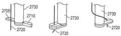
도 18a 및 도 18b는 봉합사 전달 장치 핸들(1800)의 일 실시예를 도시한다. 실시예들에 있어서, 봉합사 단부들(1805,1810)은 핸들(1800)이 수술 개방부 안으로 삽입되기 전에 핸들(1800) 상으로 적재될 수 있다. 도 18a에 있어서, 봉합사 단부들(1805,1810)은 바늘 트랙(150,155)의 원위 개방부(152,157)에 있는 핸들(1800) 상으로 적재될 수 있다. 도 18b는 봉합사를 적재하는 마찰 방법을 도시한다. 도 18b에서, 슬롯(1815,1820)은 예를 들어, 압착 끼워맞춤 또는 다른 쐐기결합 작용에 의해서 봉합사 단부들(1805,1810)을 보유하도록 구성된다. 대안 실시예에 있어서, 가요성 보유 플랩(1825,1830)은 봉합사 단부들(1805,1810)을 추가로 보유하기 위하여 부가된다. 플랩(1825,1830)은 원하는 보유력에 따라서 예를 들어 고무 또는 금속일 수 있다. 더우기, 핸들(1800)은 공장 조립 프로세스 중에 적재된 봉합사 단부들(1805,1810)을 가질 수 있다.18A and 18B show one embodiment of a suture
도 19a 및 도 19b는 봉합사 카세트를 사용하여 봉합사를 적재하기 위한 일 실시예를 도시한다. 도 19a에서, 카세트(1905)는 하나의 봉합사(1910)를 저장하고 봉합사 단부들(1915,1920)에 대한 접근성을 제공하는 2개의 접근 포트를 가진다. 도 19b에서, 핸들(1900)은 봉합사 카세트(1905)를 수용하고 봉합사를 전개하기 위하여 준비할 때 봉합사 패서 상으로 적재하기 위해 핸들(1900) 내에 내부에 있는 바늘 트랙(150,155) 내에 노출된 봉합사 단부들(1915,1920)을 배치하도록 구성된 카세트 삽입 포트(1925)를 가진다.19A and 19B show one embodiment for loading sutures using a suture cassette. In FIG. 19A ,
일 실시예에 있어서, 슬릿들(115)은 제어 버튼(130)을 누를 때 봉합될 조직을 압박하도록 스프링 적재된다. 따라서, 실시예에 있어서, 제어 버튼(130)을 누르는 것은 2개의 작용들을 유발할 수 있다. 첫째, 캐처(110)는 전개될 수 있고 둘째 슬릿들(115)은 캐처(110)를 향하여 원위로 이동하도록 압송될 수 있다. 이들 작용들은 슬라이더가 캐처(110)로부터 멀리 근위로 이동할 때 적재되는 스프링으로 달성될 수 있다. 스프링은 제어 버튼(130)을 누를 때 먼저 캐처(110)를 개방하도록 버튼 스트로크의 최종 스테이지에 의해서 작동되는 트리거를 가질 수 있고 제어 버튼(130)이 임의의 추가 량으로 눌러질 때, 트리거는 스프링을 해제하도록 작동하고, 이는 그 다음 피부를 향하여 슬라이더(115)를 눌러서, 슬라이더(115) 및 캐처(110) 사이에 조직을 개재한다.In one embodiment, the
도 20a 내지 도 20c는 날개부들이 캐처 지지대들의 가요성 섹션들이고 봉합사를 포획하는 것을 보조하는 일 실시예를 도시한다. 도 20a는 지지대들(112,114,312,314)(도 3)과 치수 및 강성도에서 유사한 섹션들을 갖는 지지대들(912,914,916,918)을 도시한다. 지지대들(912,914,916,918)은 가요성 날개부들(1905,1910,1915,1920)을 가진다. 도 20b는 후퇴할 때 캐처(110) 내에서 접혀지는 가요성 날개부들(1905,1910)을 도시한다. 캐처(110)가 전개될 때, 날개부들(1905,1910,1915,1920)은 그 의도한 위치들로 개방되고 날개부 쌍들(912,916 및 914,918)은 중첩되어서, 도 20a에 있는 봉합사를 위한 목표 영역을 제공한다. 실시예에서, 중첩 날개부 쌍들에 의해서 제공된 목표 영역은 멤브레인(302,305)(도 3)에 의해서 제공되는 것과 유사한 평면이고, 또 날개부들(1905,1910,1915,1920)은 지지를 위한 장력에 의존하지 않으므로 이들은 지지대들(912,914,916,918)에 의해서 형성된 영역을 지나서 연장되도록 구성될 수 있다. 날개부들(1905,1910,1915,1920)은 멤브레인(302,305)과 유사하게 천공됨으로써 봉합사를 포획하는 것을 보조하거나 또는 봉합사 패서(200)가 날개부 쌍들 사이의 이음매(1925,1930)를 통과하는 것을 허용함으로써 봉합사를 포획하는 것을 보조할 수 있다. 일단, 봉합사 패서(200)가 이음매(1925,1930)를 통과하고, 봉합사를 해제하고 후퇴하면, 날개부 쌍(1905,1915 또는 1910,1920)은 전개된 봉합사 주위에서 폐쇄되고 포획한다. 포획된 봉합사 단부들은 그 다음 캐처(110)가 후퇴되고(도 20c) 지지대 쌍(912,916 또는 914,918)에 의해서 더욱 굳게 파지될 때 날개부 쌍에 의해서 당겨질 수 있다.20A-20C show one embodiment in which the wings are flexible sections of catcher supports and assist in capturing the suture. FIG. 20A shows
도 21a 내지 도 21e는 캐처 멤브레인이 침투되는 위치를 변화시킴으로써 다용도 캐처 멤브레인을 허용하는 실시예들을 도시한다. 일반적으로, 멤브레인을 통한 바늘의 각각의 삽입은 멤브레인에 흔적을 생성하고 남긴다. 다수의 바늘 삽입에 의해서, 멤브레인에 생성된 구멍들은 봉합사들을 포획 및 보유하는 멤브레인의 기능을 감소시킬 수 있다. 실시예들은 각각의 사용을 위하여 봉합사 패서에 의해서 침투된 영역을 변화시킴으로써 동일 장치의 다용도를 제공한다. 봉합사 캐처는 바늘 침투를 위한 의도된 멤브레인 영역이 매번 (충분히) 상이하도록 회전할 수 있다. 회전은 의도한 수의 바늘 침투 및 허용가능한 반복된 바늘 침투에 따라서 크거나 또는 작은 각도일 수 있다. 다른 실시예들은 예를 들어 봉합사 캐처의 임의의 회전을 반복적으로 제공함으로써 동일 영역에서 바늘 침투의 개연성을 감소시킨다.21A-21E illustrate embodiments that allow for a versatile catcher membrane by varying the position at which the catcher membrane penetrates. In general, each insertion of the needle through the membrane creates and leaves a mark on the membrane. By inserting multiple needles, the pores created in the membrane can reduce the ability of the membrane to capture and retain the sutures. Embodiments provide the versatility of the same device by varying the area penetrated by the suture passer for each use. The suture catcher can be rotated so that the intended membrane area for needle penetration is (sufficient) different each time. The rotation can be a large or small angle depending on the intended number of needle penetrations and the acceptable repeated needle penetrations. Other embodiments reduce the likelihood of needle penetration in the same area, for example by repeatedly providing any rotation of the suture catcher.
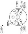
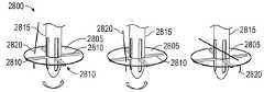
도 21a 및 도 21b는 임의의 회전 기구에 의한 다용도 캐처의 일 실시예를 도시한다. 본 실시예에서, 캐처의 지지대들은 핸들 샤프트에 대한 규정된 거리 내에서 선회될 수 있다. 지지대들에 부착된 멤브레인은 지지대들과 함께 회전할 수 있다. 도 21a에서, 단일 지지대(2010)는 명확성을 위하여 영상화되고 다음 설명은 캐처의 다른 지지대들에 적용된다. 캐처 지지대(2010)는 샤프트(2005)에서 윈도우(2020) 내에서 각도(2015) 주위로 자유롭게 선회된다. 윈도우(2020)의 크기는 캐처 지지대(2010)가 얼마나 많이 회전할 수 있는지를 규정할 수 있다. 윈도우(2020)는 캐처의 각각의 지지대에 대한 근위 부분[예를 들어, 근위 연결 부분(1115)(도 11)]에 제공되어서, 각각의 개별 지지대가 윈도우들 내에서 자유롭게 이동하는 것을 허용한다. 원위 조인트 및 제어 로드 사이의 연결부는 근위 조인트의 회전이 결과적으로 전체 캐처의 회전을 유도하도록 부유할 수 있다. 본 실시예에서 허용된 캐처의 임의의 회전은 2개의 바늘들이 동일 위치에서 정확하게 멤브레인을 침투할 개연성을 감소시킨다. 도 21b는 도 21a에서 지지대들이 설치된 캐처의 회전으로부터 발생할 수 있는 멤브레인에서의 천공 패턴을 도시한다. 도 21b에서, 멤브레인(2025)은 캐처 및 멤브레인이 각도(2015) 내에서 회전할 때 단일 바늘 트랙, 예를 들어 바늘 트랙(155)(도 3) 내에서 봉합사 패서의 사용으로부터 발생할 수 있는 천공부(2030a,2030b,2030c)를 도시한다.21A and 21B show one embodiment of a multipurpose catcher with an optional rotating mechanism. In this embodiment, the supports of the catcher can be pivoted within a prescribed distance relative to the handle shaft. A membrane attached to the supports can rotate with the supports. In FIG. 21A , a
도 21c는 내부 선회 지점을 갖는 바늘 트랙을 구비한 다용도 캐처의 일 실시예를 도시한다. 바늘 트랙(2105)은 삽입 지점(2110) 및 협소부(2120) 사이와 출구 지점(2115) 및 협소부(2120) 사이의 바늘 또는 봉합서 패서보다 직경이 클 수 있다. 협소부(2120)는 선회 지점으로서 작용하는 바늘 트랙(2105) 내의 동일 위치에 있는 바늘 트랙(2105)의 협착 또는 단순한 범프일 수 있다. 바늘 또는 봉합사 패서가 바늘 트랙(2105) 내에서 방사상으로 이동할 수 있는 상태에서, 협소부(2120)는 예시적인 봉합사 패서 위치(2125,2130)에 의해서 표시된 바와 같이 봉합사 패서 또는 바늘의 근위 단부를 이동시킴으로써 봉합사 캐처(2135)의 표면에 대한 봉합사 패서 또는 바늘의 원위 단부를 이동시키는 것을 용이하게 하도록 선회 지점으로서 작용할 수 있다. 봉합사 패서 위치(2125,2130)는 실시예에 대해서 봉합사 패서가 샤프트(2140) 및 봉합사 캐처(2135)에 대한 여러 각도에서 바늘 트랙(2105)을 나오는 것을 제시한다. 변화 각도는 바늘이 동일 위치에서 정확하게 봉합사 캐처(2135)에 있는 멤브레인을 침투할 개연성을 감소시킨다. 일 실시예에서, 바늘 트랙(2105)은 모래시계 형상일 수 있다. 추가 실시예에 있어서, 바늘 트랙(2105)은 협소부(2120)를 갖지 않지만, 일반적으로 바늘 또는 봉합서 패서보다 직경이 커서 예시적인 봉합사 패서 위치들(2125)을 허용한다.21C shows one embodiment of a utility catcher having a needle track having an internal pivot point. The
도 21d는 다용도의 캐처 멤브레인을 제공하는 핸들(2200)의 평면도를 도시한다. 도 21d에서, 다수의 바늘 트랙 쌍들(2205a 및 2205b, 2210a 및 2210b, 2215a 및 2215b)은 멤브레인의 상이한 각각의 영역들(미도시)을 목표로 한다. 또한, 다이얼 형태부(미도시)는 적절한 시간에 한 세트의 바늘 트랙들을 노출시키기 위하여 상단 핸들(2200)을 회전시킬 수 있다.21D shows a top view of a
도 21e는 자동 펜 회전 기구를 사용하는 다용도 실시예의 단면을 도시한다. 봉합사 캐처의 회전은 바늘 또는 봉합사 패서가 멤브레인의 비사용 위치에서 멤브레인을 침투하는 것을 보장할 수 있다. 실시예에서, 자동 펜 회전 기구(2300) 또는 변형체는 이를 달성하기 위해 사용될 수 있다. 기구(2300)는 제어 로드(2305)의 상하 이동을 제어 로드(2305)의 회전 이동으로 전달하는 형태부를 수용한다. 제어 로드(2305)의 회전이 결과적으로 원위 조인트의 회전을 유도하도록 제어 로드(2305)가 봉합사 캐처의 원위 조인트에 연결되고, 봉합사 캐처의 근위 조인트가 봉합사 캐처의 회전 이동을 허용하는 상태에서, 제어 로드(2305)의 회전은 결과적으로 봉합사 캐처의 회전을 유도할 것이다. 결과적 회전량은 회전 기구(2300)의 디자인에 비례하여 제어되고 임의로 작아지거나 또는 커질 수 있다. 본 실시예의 변형예에서, 제어 로드(2305)의 상하 이동은 결과적으로 봉합사 캐처의 근위 조인트의 회전 이동을 유도하고, 원위 조인트 및 제어 로드 사이의 연결은 부유하며 근위 조인트의 회전은 결과적으로 전체 봉합사 캐처의 회전을 유도한다.21E shows a cross-section of a versatile embodiment using an automatic pen rotation mechanism. Rotation of the suture catcher may ensure that the needle or suture passer penetrates the membrane in an unused position of the membrane. In an embodiment, an automatic
실시예들은 핸들에서 사전 적재되는 봉합사들을 수용하도록 설계된 팁을 갖는 봉합사 패서를 사용한다(예를 들어, 핸들에서 봉합사들을 적재하는 것과 관련된 도 18a 및 도 18b를 참조). 이러한 실시예들에서, 봉합사 패서의 팁은 양호하게는 복부 조직에 진입하기 전에 봉합사 단부들을 파지하고; 캐처가 그렇게 설비되고 봉합사 단부들을 사용한다면, 봉합될 조직 및 캐처 멤브레인을 침투하면서 봉합사 단부들을 보유할 수 있다.Embodiments use a suture passer with a tip designed to receive preloaded sutures from the handle (see, eg, FIGS. 18A and 18B related to loading sutures from the handle). In such embodiments, the tip of the suture passer preferably grips the suture ends prior to entering the abdominal tissue; If the catcher is so equipped and uses suture ends, it can retain the suture ends while penetrating the tissue to be sutured and the catcher membrane.
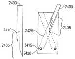
도 22a 내지 도 22d는 봉합사를 파지, 보유 및 전개하도록 설계된 봉합사 패서들의 상이한 실시예들을 도시한다. 도 22a에서, 봉합사 패서(2400)는 바늘 트랙(2425)의 출구(2420)에 배치된 봉합사(2415)를 결합하도록 구성된 슬롯(2410)을 갖는 고정 팁(2405)을 가진다. 도 22b에서, 봉합사 패서(2430)는 장치(2455), 예를 들어 봉합사 패서(2430)의 내부에 있는 구동 액슬의 추진시에 고정 부재(2450)에 대해서 봉합사(2445)를 체결하기 위한 체결 부재(2440)를 갖는 작동 팁(2435)을 구비한다. 도 22c에서, 봉합사 패서(2460)는 바늘 튜브(2485)를 향하여 봉합사(2480)를 파지하기 위한 내부 로드(2475)에 의해서 작동된 바늘 헤드(2470)를 갖는 파지 팁(2465)를 구비한다. 도 22d는 비교를 위하여 도 2a 및 도 2b에 대해서 미리 기술된 봉합사 패서(200)의 파지 팁을 도시한다. 봉합사 패서의 본 실시예는 또한 핸들 상에 사전 적재되는 봉합사들을 수용하는데 사용될 수 있다. 유사하게, 도 22a 내지 도 22c에 있는 봉합사 패서들의 실시예들은 핸들의 바늘 트랙 안으로 삽입되기 전에 봉합사로 적재될 수 있다. 실시예들에서, 임의의 바늘 팁 실시예들은 개시된 임의의 바늘 트랙과 협력하도록 구성될 수 있다.22A-22D show different embodiments of suture passers designed to grip, hold, and deploy a suture. In FIG. 22A ,
봉합될 조직이 핸들(예를 들어, 도 8b 참조)에 의해서 개재된 후에 핸들에 적재되는 봉합사를 전개하기 위한 절차의 일 실시예에서, 봉합사 패서는 팁이 핸들에 적재된 봉합사에 도달할 때까지 바늘 트랙 안으로 그리고 바늘 트랙을 통해서 삽입된다. 봉합사는 그 다음 봉합사 패서 상으로 적재된다. 그 다음, 봉합사 패서는 캐처 상에 봉합사 단부를 전개하기 위하여 바늘 트랙을 통해서 삽입된다. 캐처 구성에 따라서, 봉합사는 캐처 지지대의 파지 거리 내에서 해제됨으로써 전개되거나 또는 캐처 멤브레인 안으로 삽입됨으로써 전개되고 그 다음 해제될 수 있다. 봉합사가 해제된 후에, 봉합사 패서는 후퇴되고 핸들에 적재된 제 2 봉합사로 반복된 상기 절차에 의해서 제 2 바늘 트랙 안으로 삽입될 수 있다.In one embodiment of a procedure for deploying a handle-loaded suture after the tissue to be sutured has been interposed by the handle (see, eg, FIG. 8B ), the suture passer waits until the tip reaches the handle-loaded suture. It is inserted into and through the needle track. The suture is then loaded onto the suture passer. The suture passer is then inserted through the needle track to deploy the suture end onto the catcher. Depending on the catcher configuration, the suture may be deployed by releasing within the gripping distance of the catcher support or deployed by insertion into the catcher membrane and then released. After the suture is released, the suture passer can be retracted and inserted into the second needle track by repeating the above procedure with a second suture loaded on the handle.
도 23a 및 도 23b는 봉합사 패서가 핸들(2500) 안으로 통합되는 실시예의 단면도를 도시한다. 도 23a에서, 봉합사 패서(2505,2510)는 각각 바늘 트랙(2515,2520) 내에 각각 위치하고 봉합사를 전개하는데 사용된다. 봉합사 패서(2505,2510)는 바늘 트랙(2515,2520) 내에서 잔류하도록 설계될 수 있다. 제어 버튼(2540)(또는 제어 레버 또는 제어 슬라이더)은 작동 시에 봉합사 패서(2505,2510)가 바늘 트랙(2515,2520)을 통해서 이동하고, 적재된 봉합사들을 파지하고 핸들(2500)의 샤프트(105)로부터 연장되며 봉합될 조직, 예를 들어 복부 조직을 침투하게 한다. 봉합사 패서(2505,2510)는 그 다음 봉합사를 캐처(110) 상으로 전개시킬 수 있다.23A and 23B show cross-sectional views of an embodiment in which a suture passer is incorporated into
실시예에서, 봉합사 패서(2505,2510)는 봉합사들을 전개시키기 위하여 2개의 봉합사 패서들을 바늘 트랙(2515,2520)을 통해서 전진시키도록 롤러 및 트랙(2545) 및 제어 버튼(2540)을 사용하여 전개될 수 있다. 롤러 및 트랙(2545)은 작동 아암(2560)에 연결된 트랙(2555) 내의 롤러(2550)를 포함할 수 있다. 제어 버튼(2540)은 눌려질 때 롤러 및 트랙(2545) 및 작동 아암(2560)이 핸들(2500)의 원위 단부(2525)를 향하여 이동시키게 유도할 수 있다. 작동 아암(2560)은 그 다음 봉합사 패서(2505,2510)를 바늘 트랙(2515,2520)을 통해서 강제실행하여 봉합사들을 전개시킨다. 롤러 및 트랙(2545)은 아암(2560)이 원위 방향으로 이동할 때 작동 아암(2560)이 핸들(2500) 내에서 내향으로 이동하게 허용하도록 구성된다. 도 23b에서, 제어 버튼(2540)은 완전히 눌려져서, 봉합사 패서(2505,2510)가 캐처(110)를 지나서 연장되어서 봉합사 패서 팁들(예를 들어, 도 22b 내지 도 22d 참조)을 개방하고 봉합사들(미도시)을 배치하도록 강제실행한다. 제어 버튼(2540)의 동작은 서두에 기재된 바와 같이 캐처(110) 및 또한 슬라이더(115)를 제어하는 제어 버튼(130)을 드러낸다. 상기 동작은 또한 바늘 트랙(2515,2520)의 윤곽을 따르는 작동 아암(2560)에 반응하여 롤러(2550)가 바늘 트랙(2555) 내에서 내향으로 이동하게 유도하였다. 일 실시예에서, 제어 버튼(130,2540)의 기능은 단일 제어 버튼에 의해서 실행된다.In an embodiment,
봉합사 전달 장치들의 실시예들은 봉합사 패서를 삽입 및 후퇴시키기 위해 그리고 봉합사를 포획, 보유 및 고정하기 위한 방법을 실행하는데 사용될 수 있다. 실시예들에서, 멤브레인 특성은 봉합사를 포획, 보유 및 고정하는 것에 영향을 미친다. 상술한 바와 같이, 봉합사를 운반하는 바늘 또는 봉합사 패서가 멤브레인을 통해서 삽입될 때, 봉합사는 멤브레인에 의해서 해제 및 포획될 수 있다. 캐처가 그 다음 폐쇄될 때, 멤브레인은 캐처 프레임 폐쇄체로 접혀져서, 봉합사를 멤브레인 내에서 보유한다. 멤브레인은 자체적으로 멤브레인의 봉합사 보유 특성을 증가시키는 디자인을 추가로 갖거나 또는 높은 마찰 계수를 갖는 재료로 제조될 수 있다. 보유 특성은 재료 표면 또는 재료 층의 수 또는 재료 두께의 함수일 수 있다. 보유 특성은 보유 표면의 일측 또는 양측에 있을 수 있다.Embodiments of suture delivery devices may be used to implement methods for inserting and retracting a suture passer and for capturing, retaining, and securing a suture. In embodiments, membrane properties affect capturing, retaining, and securing the suture. As described above, when the needle or suture passer carrying the suture is inserted through the membrane, the suture may be released and captured by the membrane. When the catcher is then closed, the membrane is folded into the catcher frame closure, retaining the sutures within the membrane. The membrane itself may additionally have a design that increases the suture retention properties of the membrane, or it may be made of a material with a high coefficient of friction. Retention properties may be a function of the material surface or number of material layers or material thickness. The retention properties may be on one or both sides of the retention surface.
실시예들에서, 봉합사는 캐처 지지대 에지들에 의해서 고정될 수 있다. 다수의 방법들은 봉합사가 장치의 원위 단부에 고정되는 것을 보장하기 위하여 (개별적으로 또는 조합하여) 사용될 수 있다. 봉합사의 기계적 체결은 수술 개방부로부터 봉합사 전달 장치의 후퇴 중에 봉합사를 보유하는데 사용될 수 있다. 인접 지지대들의 에지는 봉합사를 (기계적 클램프로서) 고정되게 유지하는데 사용될 수 있다. 봉합사 캐처에 멤브레인이 설비되는 실시예들에 있어서, 멤브레인 보유력은 봉합사가 멤브레인과 적절하게 결합될 때에도 봉합사 상의 봉합 조직에 의해서 작용하는 힘을 지탱하기에 충분하지 않다. 따라서, 인접 캐처 지지대들은 봉합사를 고정하기 위해서 클램프로서 사용될 수 있다. 이러한 인접 지지대들은 (예를 들어, 멤브레인을 포함하지 않는 실시예들에서) 독립적으로 사용되거나 또는 (예를 들어, 멤브레인을 포함하는 캐처 실시예들에서) 멤브레인과 조합하여 사용될 수 있다.In embodiments, the suture may be secured by catcher support edges. A number of methods can be used (either individually or in combination) to ensure that the sutures are secured to the distal end of the device. Mechanical engagement of the suture may be used to retain the suture during retraction of the suture delivery device from the surgical opening. The edges of adjacent supports can be used to hold the suture fixed (as a mechanical clamp). In embodiments in which the suture catcher is equipped with a membrane, the membrane retention force is not sufficient to support the force acting by the suture tissue on the suture even when the suture is properly engaged with the membrane. Thus, adjacent catcher supports can be used as clamps to secure the suture. These adjacent supports may be used independently (eg, in embodiments that do not include a membrane) or may be used in combination with a membrane (eg, in catcher embodiments that include a membrane).
도 24a 내지 도 24e는 체결면의 길이 또는 체결면의 수 또는 접촉 지점들의 수를 변화시키는 캐처의 실시예들을 도시한다. 도 24a에서, 지지대(2620)의 지지대 에지(2605,2610)는 봉합사(2615)와의 접촉면을 증가시키도록 각도형성된다. 즉, 캐처 프레임 지지대들의 에지들은 경사지고 봉합사는 경사 에지들의 길이에 대한 지지대와 접촉한다. 도 24b에서, 지지대(2625,2630)는 봉합사(2615)를 향한 단일 접촉 지점(2635)을 생성하도록 구성된다. 도 24c에서, 지지대(2640)는 지지대(2650)와 상이하게 크기설정된다. 봉합사(2615)는 한 쌍의 다르게 크기설정된 지지대(2640,2650)의 표면들 사이에 체결된다. 도 24d에서, 지지대 에지(2655,2660)는 결합하여 봉합사 접촉면(2665)에서 각도를 생성한다. 각도는 예를 들어 90도일 수 있다. 캐처 지지대들은 또한 봉합사 접촉 에지들을 따라서 톱니 치형체 또는 파형 에지를 가질 수도 있다. 이러한 에지들을 갖는 디자인의 장점은 봉합사에 인가된 힘의 방향이 변화되어서, 봉합사를 따른 지점들에서 법선 힘을 증가시킨다는 것이다. 도 24e에서, 지지대(2670)는 도 24b의 구성에 부가되어서, 추가 봉합사 접촉 지점(2637)을 생성한다.24A-24E show embodiments of a catcher that vary the length of the engagement surface or the number of engagement surfaces or the number of contact points. In FIG. 24A , the support edges 2605 , 2610 of the
실시예들에서, 방금 상술한 다양한 지지대 디자인에 추가하여, 지지대 에지들은 거칠고, 처리되고, 코팅되거나 또는 마찰을 증가시키고 봉합사 고정 성능을 증가시키도록 처리된다. 예를 들어, 고무 패드 또는 스트립 또는 고무 코팅이 지지대 에지들에 도포될 수 있다.In embodiments, in addition to the various support designs just described above, the support edges are roughened, treated, coated or treated to increase friction and increase suture anchoring performance. For example, a rubber pad or strip or a rubber coating may be applied to the support edges.
캐처의 대안 실시예에서, 봉합사는 지지대가 내향으로 접혀질 때 평탄 표면을 지지대에 제공하는 제어 로드 주위에 배치된 블록을 향하거나 또는 제어 로드를 향하여 내향으로 접혀지는 캐처 지지대 사이에 체결될 수 있다. 이러한 실시예들에서, 멤브레인 및 봉합사는 모두 외부 요소(지지대) 및 내부 요소(제어 로드 또는 제어 로드 주위의 블록) 사이에 체결될 수 있다. 봉합사를 체결하는 유효성은 봉합사 캐처의 충분한(또는 완벽한) 폐쇄와 연계되기 때문에, 인가된 폐쇄력 및 멤브레인에 의해서 유발된 임의의 간섭 수준은 체결 유효성에 영향을 미칠 수 있다.In alternative embodiments of the catcher, sutures may be fastened between catcher supports that are folded inwardly towards or towards a block disposed about a control rod that provides a flat surface to the support when the support is folded inward. . In such embodiments, both the membrane and the suture may be fastened between an outer element (a support) and an inner element (a control rod or block around the control rod). Since the effectiveness of fastening the suture is associated with sufficient (or complete) closure of the suture catcher, the applied closure force and any level of interference caused by the membrane can affect fastening effectiveness.
봉합사 캐처의 다양한 실시예들에 있어서, 지지대 폐쇄력을 증가시키면, 지지대 상에 보유력을 증가시킬 수 있다. 결과적으로, 수술 개방부로부터 봉합사 전달 장치의 더욱 강력한 추출 중에 봉합사를 보유할 수 있다.In various embodiments of the suture catcher, increasing the support closure force may increase the retention force on the support. As a result, it is possible to retain the suture during more powerful extraction of the suture delivery device from the surgical opening.
실시예들에서, 포획면, 예를 들어, 멤브레인 없이 캐처에 의해서 보유될 수 있다. 이러한 실시예들에서, 캐처의 지지대들은 봉합사를 직접 체결할 수 있다. 체결 작용은 수술 개방부로부터 추출을 위해 후퇴되는 캐처의 일부일 수 있다.In embodiments, it may be retained by a catcher without a capture surface, eg, a membrane. In such embodiments, the supports of the catcher may directly engage the suture. The fastening action may be the portion of the catcher that is retracted for extraction from the surgical opening.
도 25 내지 도 27은 봉합사를 전달 및 포획하기 위한 추가 실시예들을 도시한다. 도 25a, 도 25b 및 도 26은 수술 개방부의 일측 상의 봉합사를 포획하고 상기 봉합사를 봉합을 완료하기 위해 다른 측으로 이동시키기 위한 실시예들을 도시한다. 도 25a 및 도 25b는 봉합사 단부(2720)를 포획하기 위하여 방향(2707,2712)으로 선회되는 체결 아암(2705,2710)을 갖는 체결 장치(2700)의 각각의 상면도 및 사시도를 도시한다. 체결 아암(2705)은 내부 샤프트(2725)에 의해서 회전될 수 있고 체결 아암(2710)은 외부 샤프트(2730)에 의해서 회전될 수 있다. 체결 장치(2700)는 예를 들어, 도 1a 및 도 1b의 핸들(100) 상의 캐처(110)를 대체할 수 있다. 체결 장치(2700)는 봉합사(2720)를 포획하는데 사용될 수 있고 수술 개방부 내에서 체결 장치(2700)의 반대측 상에 배치될 수 있다.25-27 show additional embodiments for delivering and capturing sutures. 25A, 25B, and 26 illustrate embodiments for capturing a suture on one side of a surgical opening and moving the suture to the other side to complete the suture. 25A and 25B show top and perspective views, respectively, of a
도 26은 포획 장치(2800)의 반대측 상에 포획된 봉합사(2820)를 배치하기 위하여 샤프트(2815) 주위에 선회되는 지지대(2810)에 의해서 지지되는 대면적 멤브레인(2805)를 갖는 포획 장치(2800)의 사시도를 도시한다. 봉합사(2820)는 상술한 바와 같이 멤브레인(2805)에 의해서 포획될 수 있다. 포획 장치(2800)는 또한 예를 들어, 도 1a 및 도 1b의 핸들(100) 상의 캐처(110)를 대체할 수 있다.26 shows a
일 실시예는 우산형 멤브레인을 포함할 수 있고, 여기서 멤브레인은 여러개의 방사상 팽창 지지대들에 의해서 지지되고 장치 주위에서 360도에 걸쳐 있다. 우산과 같이, 멤브레인은 인장 상태에 있어서, 바늘이 멤브레인 재료를 침투하기가 더욱 용이하게 한다. 또한, 멤브레인 재료 및 봉합사 사이의 마찰은 봉합사 패서가 후퇴할 때 봉합사를 분리 및 보유하기에 충분할 수 있다. 대안 실시예는 각 층이 상이한 배향을 갖는 다층 멤브레인을 포함할 수 있다. 이러한 다층 멤브레인에서, 봉합사는 격자 구조에서 마찰 및 억매임 모두로 인하여 봉합사 패서로부터 분리될 수 있다.One embodiment may include an umbrella membrane, wherein the membrane is supported by a number of radially expanded supports and spans 360 degrees around the device. Like an umbrella, the membrane is in tension, making it easier for the needle to penetrate the membrane material. Also, friction between the membrane material and the suture may be sufficient to separate and retain the suture when the suture passer retracts. Alternative embodiments may include a multilayer membrane with each layer having a different orientation. In such multilayer membranes, the sutures can be separated from the suture passers due to both friction and restraint in the lattice structure.
도 25a, 도 25b 및 도 26에 의해서 도시된 실시예들은 다음 방법에 따라서 사용될 수 있다. 봉합사를 운반하는 바늘(또는 봉합사 패서)은 바늘 트랙 안으로 삽입되고 그 다음 체결 장치(2700) 또는 포획 장치(2800)가 설비된 핸들을 사용하여 투관침 창상의 일측 상의 근육/근막층 안으로 삽입된다. 봉합사 패서는 봉합사를 해제하고 후퇴된다. 체결 장치(2700)에 대해서, 봉합사는 그 다음 체결 아암(2705,2710)의 움직임에 의해서 포획된다. 포획 장치(2800)에 대해서, 봉합사는 바늘 패서로부터 봉합사를 분리하고 보유하는 디자인 또는 재료 특성을 갖는 멤브레인(2805)을 침투시켰다. 일단, 봉합사가 보유되면, 봉합사는 봉합사(2720 또는 2820)가 투관침 창상의 반대측으로 재배치되게 하는 장치(2700 또는 2800)를 회전시킴으로써 이동할 수 있다. 의사는 그 다음 봉합사를 용이하게 퇴거할 수 있는데, 이는 봉합사가 핸들의 다른 바늘 트랙을 통해서 그리고 봉합될 조직을 통해서 삽입된 바늘(또는 봉합사 패서)의 목표 지점에 배치된다. 일단 봉합될 조직을 관통하면, 바늘(또는 봉합사 패서)은 복강경 이미지로부터 안내에 따라서 재배치된 봉합사를 포획할 수 있다. 포획된 봉합사는 의사가 봉합사를 퇴거하는 것을 용이하게 하는 제어된 형상, 배향 및 장력을 가질 수 있다. 이들 실시예들은 이전 실시예들과 같이 의사가 봉합사를 봉합사 패서로 파지할 수 있는 봉합사를 이동시키는 것을 돕는 보조원에 대한 필요성을 제거한다.The embodiments illustrated by Figs. 25A, 25B and 26 can be used according to the following method. The suture-carrying needle (or suture passer) is inserted into the needle track and then inserted into the muscle/fascia layer on one side of the trocar wound using a handle equipped with a
도 27은 봉합사 단부들을 수술 개방부에 연결하기 위한 일 실시예의 평면도를 도시한다. 도 27에서, 체결 장치(2900)는 원호를 통해서 제거하고 봉합사 단부(2920,2922)를 포획하기 위하여 방향(2907,2912)으로 각각 선회되는 체결 아암(2905,2910)을 가진다. 체결 아암(2905)은 내부 샤프트(2925)에 의해서 회전하고 체결 아암(2910)은 외부 샤프트(2930)에 의해서 회전할 수 있다(대안으로, 단지 하나의 체결 아암은 봉합사 단부들을 모두 포획하기 위하여 회전한다). 체결 장치(2900)는 예를 들어, 도 1a 및 도 1b의 핸들(100) 상의 캐처(110)를 대체할 수 있다. 체결 장치(2900)는 봉합사 단부(2920,2922)를 포획하고 이들을 링크 요소(2935)와 함께 연동하는데 사용될 수 있다. 링크 요소(2935)는 체결 아암(2905,2910) 중 하나에 부착된 크림프 또는 생분해성 부재일 수 있다. 이는 또한 클램프 또는 클립일 수 있다. 추가로, 봉합사 단부(2920,2922)는 접착제 또는 열 등을 사용하여 연동될 수 있다. 결과적 봉합사 연동부는 바늘 또는 봉합사 패서에 의해서 생성된 조직 트랙을 통해서 봉합사 조인트를 당기는 것을 유지하기에 적어도 충분히 강해야 한다. 대안으로, 봉합사 연동부는 창상 폐쇄부를 제공할 만큼 충분히 강해야 한다.27 shows a top view of one embodiment for connecting suture ends to a surgical opening. In FIG. 27 ,
체결 장치(2900)는 다음 방법에 따라서 사용될 수 있다. 스위퍼 또는 체결 아암들은 초기에 봉합사 전달과 간섭되지 않도록 배치된다. 2개의 봉합사 단부들은 투관침 창상의 반대측 상에 전달된다. 체결 아암은 그 다음 봉합사 단부들을 링크 요소와 접촉되게 회전한다. 봉합사 단부 및 링크 요소는 그 다음 봉합사를 연동시키기 위하여 체결 아암에 의해서 함께 눌려진다. 봉합사 전달 장치는 그 다음 후퇴할 수 있다.The
본 실시예에서, 봉합을 마무리하기 위한 하나의 선택사항은 한 봉합사의 2개의 단부들을 전달하는 단계를 포함한다. 일단 2개의 봉합사 단부들이 연동되면, 연동된 봉합사는 루프가 된다. 사용자는 투관침 창상의 외부 - 근위 단부에서 봉합사를 절단할 수 있다. 그 다음, 사용자는 창상을 폐쇄하기 위하여 외부 봉합사 단부들을 당기고 단부들을 매듭지울 수 있다. 대안으로, 사용자는 봉합사 전달 장치에 의해서 수술 개방부로부터 봉합사 링크부를 당기거나 또는 초기 바늘 삽입에 의해서 생성된 조직 트랙을 통해서 링크부룰 이동시키기 위해서 봉합사 루프의 일 측에서 세게 당길 수 있다. 사용자는 그 다음 봉합사 조인트를 절단하고 수술 개방부를 폐쇄하며 매듭을 묶을 수 있다. 다른 선택사항은 2개의 봉합사 단부들을 복부 안으로, 각 단부를 개별 봉합사로부터 전달하는 것이다. 일단 2개의 봉합사 단부들은 연동되면, 사용자는 상술한 바와 같이, 장치를 후퇴할 수 있고 봉합사를 마무리할 수 있다.In this embodiment, one option for finishing the suture comprises delivering the two ends of one suture. Once the two suture ends are interlocked, the interlocked suture becomes a loop. The user may cut the suture at the outer-proximal end of the trocar wound. The user can then pull the outer suture ends and knot the ends to close the wound. Alternatively, the user may pull the suture linkage from the surgical opening with the suture delivery device or pull hard on one side of the suture loop to move the linkage through the tissue track created by the initial needle insertion. The user can then cut the suture joint, close the surgical opening, and tie a knot. Another option is to deliver the two suture ends into the abdomen, each end from a separate suture. Once the two suture ends are engaged, the user can retract the device and finish the suture, as described above.
일 실시예에 있어서, 캐처 폐쇄 기구는 슬라이더 작동된다. 봉합사 전달 장치는 복강에서 대항력 부재(예를 들어, 캐처)를 향하여 복벽 조직을 개재하도록 배치될 수 있는 활주 부재를 가질 수 있다. 기술된 많은 실시예들은 이 방식으로 구성된다. 본 실시예에서, 활주 부재는 활주 부재의 이동이 캐처의 개폐를 제어하는데 사용될 수 있도록 캐처 전개 기구에 결합될 수 있다. 활주 부재가 전개 기구에 결합된 상태에서, 활주 부재가 아래로 (장치의 원위 단부를 향하여) 이동할 때, 캐처 전개 기구는 캐처를 개방시키도록 작동될 수 있다. 활주 부재가 위로 (장치의 근위 단부를 향하여) 이동할 때, 캐처 전개 기구는 캐처를 폐쇄시키도록 작동될 수 있다. 활주 부재가 캐처 전개 기구와 상호작용하는 위치는 원하는대로 설계될 수 있다. 일 실시예에서, 상기 캐처는 활주 부재가 작은 거리를 아래로 이동할 때 개방될 수 있고 상기 캐처는 활주 부재가 작은 거리를 위로 이동할 때 폐쇄될 수 있다. 예를 들어, 슬라이더를 위로 이동시키는 것은 원위 조인트가 위로 이동하게 하고 그럼으로써 봉합사 캐처를 전개시킬 수 있다. 여러 기구 선택사항은 본 개념을 구현하는데 사용될 수 있다.In one embodiment, the catcher closing mechanism is slider actuated. The suture delivery device may have a sliding member that may be positioned to interpose the abdominal wall tissue in the abdominal cavity towards the opposing force member (eg, catcher). Many of the described embodiments are constructed in this manner. In this embodiment, the slide member may be coupled to the catcher deployment mechanism such that movement of the slide member may be used to control opening and closing of the catcher. With the slide member coupled to the deployment mechanism, when the slide member moves down (toward the distal end of the device), the catcher deployment mechanism may be actuated to open the catcher. When the slide member moves upward (toward the proximal end of the device), the catcher deployment mechanism may be actuated to close the catcher. The location where the slide member interacts with the catcher deployment mechanism may be designed as desired. In one embodiment, the catcher can open when the slide member moves down a small distance and the catcher can close when the slide member moves up a small distance. For example, moving the slider upward may cause the distal joint to move upward, thereby deploying the suture catcher. Several instrument options may be used to implement the present concept.
일 실시예를 사용하는 방법은 원위 단부가 캐비티 내에 있을 때까지 봉합사 전달 장치를 조직 트랙을 통해서 삽입하는 단계; 캐처를 개방하고 그 다음 캐처 및 활주 부재 사이의 복벽 조직을 개재하도록 장치 원위 단부를 향하여 활주 부재를 이동시키는 단계; 봉합사가 해제되고 원위 단부에 보유될 때까지(또는 봉합사가 해제되고 캐처에 의해서 포획될 때까지) 봉합사 운반 바늘을 장치 안으로 삽입함으로써 봉합사를 봉합사 보유 요소(캐처)로 전달하는 단계; 캐처를 폐쇄하고 복벽 조직을 해제하기 위하여 장치의 근위 단부를 향하여 활주 부재를 이동시키는 단계; 그리고 장치의 원위 단부에 보유된 봉합사 단부들을 갖는 캐비티로부터 봉합사 전달 장치를 후퇴시키는 단계를 포함할 수 있다.A method using one embodiment includes inserting a suture delivery device through a tissue track until the distal end is within the cavity; opening the catcher and then moving the slide member towards the device distal end to interpose the abdominal wall tissue between the catcher and the slide member; delivering the suture to the suture retaining element (catcher) by inserting a suture delivery needle into the device until the suture is released and retained at the distal end (or until the suture is released and captured by the catcher); moving the slide member toward the proximal end of the device to close the catcher and release the abdominal wall tissue; and retracting the suture delivery device from the cavity having the suture ends retained at the distal end of the device.
봉합사를 자동으로 전개시키기 위한 방법은 봉합사 전달 장치를 봉합사 개방부 안으로 삽입시키는 단계; 창상 조직을 개재시키는 단계; 봉합사 단부들을 전개시키는 단계; 그리고 핸들을 후퇴시키는 단계를 포함할 수 있다. 창상 조직을 개재시키는 단계는 캐처가 개방되게 하고 슬라이더가 조직을 캐처를 향해서 압축시키게 하는 버튼을 누르는 단계를 추가로 포함할 수 있다. 봉합사 단부들을 전개시키는 단계는 핸들과 통합되는 봉합사 패서를 사용하거나 또는 독립적인 봉합사 패서를 사용하는 단계를 추가로 포함할 수 있다. 핸들을 후퇴시키는 단계는 봉합사들을 포획하고 자동으로 봉합사를 해제하기 위하여 캐처를 폐쇄하는 단계를 추가로 포함할 수 있다.A method for automatically deploying a suture includes inserting a suture delivery device into a suture opening; interposing wound tissue; deploying the suture ends; and retracting the handle. Interposing the wound tissue may further comprise depressing a button that causes the catcher to open and the slider compresses the tissue towards the catcher. Deploying the suture ends may further include using a suture passer integrated with the handle or using an independent suture passer. Retracting the handle may further include closing the catcher to capture the sutures and automatically release the sutures.
봉합사를 전개하기 위한 방법은 봉합사를 핸들 상으로 적재하는 단계 또는 봉합사 카세트를 핸들 안으로 적재하는 단계; 왼손으로 투관침을 제거하는 단계; 캐처가 복강경 이미지로부터 완벽히 보일 때까지 오른손으로 핸들을 투관침 창상 안으로 삽입하는 단계; 시각적 안내 하에서 조직을 개재하기 위하여 캐처를 개방하고 그 다음 슬라이더를 아래로 밀어내는 제어 버튼을 오른손으로 해제하는 단계를 포함할 수 있다. 복강경 이미지는 캐처가 복막벽과 접촉하는지를 나타내는데 사용될 수 있다. 일 실시예에서, 봉합사를 전개하기 위한 본 방법은 왼손으로 핸들을 잡는 단계; 시각적 안내 하에서 캐처 상의 봉합사를 전개시키기 위하여 오른손으로 봉합사 트랙을 통해서 삽입하는 단계; 그리고 시각적 안내 하에서 다른 바늘 트랙에서 이를 반복하는 단계를 선택적으로 포함한다. 다른 실시예에서, 봉합사를 전개하기 위한 본 방법은 왼손을 사용하여 핸들을 잡는 단계; 오른손을 사용하여 시각적 안내 하에서 캐처 상의 봉합사를 전개시키기 위해서 전개 버튼을 누르는 단계; 시각적 안내 하에서 봉합사들을 포획하기 위하여 왼손 엄지를 사용하여 제어 버튼을 누르는 단계; 왼손을 사용하여 핸들을 당기고 2개의 봉합사 단부들을 회수하는 단계를 선택적으로 포함한다.A method for deploying a suture includes loading a suture onto a handle or loading a suture cassette into the handle; removing the trocar with the left hand; inserting the handle into the trocar wound with the right hand until the catcher is completely visible from the laparoscopic image; opening the catcher to intervene the tissue under visual guidance and then releasing with the right hand a control button that pushes the slider down. Laparoscopic images can be used to show if the catcher is in contact with the peritoneal wall. In one embodiment, the method for deploying a suture includes grasping a handle with the left hand; inserting through the suture track with the right hand to deploy the suture on the catcher under visual guidance; and repeating this on another needle track under visual guidance. In another embodiment, the method for deploying a suture includes grasping a handle using the left hand; using the right hand to press the deploy button to deploy the suture on the catcher under visual guidance; depressing the control button using the thumb of the left hand to capture the sutures under visual guidance; using the left hand to pull the handle and retrieve the two suture ends.
본원에는 임의의 예시적 실시예가 기술된다. 그러나, 본 실시예와 관련된 당업자는 본원의 원리들이 다른 적용에 대한 적당한 변형으로 용이하게 확장될 수 있다는 것을 이해할 것이다.Certain exemplary embodiments are described herein. However, those skilled in the art in connection with this embodiment will understand that the principles herein may be readily extended with suitable modifications for other applications.
Claims (20)
Translated fromKorean세장형 전개 부재;
상기 세장형 전개 부재의 원위 단부에 인접 배치된 봉합사 캐처로서, 상기 봉합사 캐처가 절개부로 진입하는 것을 용이하게 하는 후퇴 구성 및 봉합사의 포획을 용이하게 하고 상기 봉합사 캐처를 상기 절개부로부터 추출하는 것에 저항하는 전개 구성 사이에서 전이되도록 구성되는 상기 봉합사 캐처;
상기 세장형 전개 부재에서 상기 봉합사 캐처에 대해 근위에 배치된 압축 부재로서, 상기 압축 부재는 상기 절개부로 진입하는 것에 저항하도록 구성된 원반형 슬라이더를 포함하며, 상기 압축 부재는 압축 구성 및 비압축 구성 사이에서 전이되는, 상기 압축 부재;
상기 압축 부재를 통하여 연장되는 제 1 바늘 트랙으로서, 상기 제 1 바늘 트랙은 상기 제 1 바늘 트랙을 통하여 전진되는 바늘을 상기 전개 구성에 있을 때 상기 봉합사 캐처의 제 1 영역과 결합되게 지향하도록 배향된 상기 제 1 바늘 트랙; 및
상기 압축 부재를 통하여 연장되는 제 2 바늘 트랙으로서, 상기 제 2 바늘 트랙은 상기 제 2 바늘 트랙을 통하여 전진되는 바늘을 상기 전개 구성에 있을 때 상기 봉합사 캐처의 제 2 영역과 결합되게 지향하도록 배향된 상기 제 2 바늘 트랙을 포함하고,
상기 전개 구성에 있을 때 상기 봉합사 캐처의 제 1 영역 및 상기 전개 구성에 있을 때 상기 봉합사 캐처의 제 2 영역은 상기 제 1 영역과 제 2 영역의 상기 절개부의 반대 측부들 상에서의 배치를 허용하기 위하여 상기 봉합사 캐처에 위치하는, 봉합사 전달 장치.A suture delivery device for suturing tissue comprising:
elongate unfolding member;
a suture catcher disposed proximate the distal end of the elongate deployment member, a retracted configuration to facilitate entry of the suture catcher into the incision and to facilitate capture of suture and resist extraction of the suture catcher from the incision the suture catcher configured to transition between deployment configurations;
a compression member disposed proximal to the suture catcher in the elongate deployable member, the compression member comprising a disc-shaped slider configured to resist entry into the incision, wherein the compression member is configured to be between a compressed configuration and an uncompressed configuration. a transitional compression member;
a first needle track extending through the compression member, the first needle track oriented to direct a needle advanced through the first needle track into engagement with a first region of the suture catcher when in the deployed configuration the first needle track; and
a second needle track extending through the compression member, the second needle track oriented to direct a needle advanced through the second needle track into engagement with a second region of the suture catcher when in the deployed configuration and the second needle track;
The first region of the suture catcher when in the deployed configuration and the second region of the suture catcher when in the deployed configuration allow for placement of the first region and the second region on opposite sides of the incision. A suture delivery device located in the suture catcher.
상기 압축 구성에서 상기 압축 부재는 상기 봉합사 캐처부터 제 1 거리에 있고 상기 비압축 구성에서 상기 압축 부재는 상기 봉합사 캐처로부터 제 2 거리에 있으며, 상기 제 1 거리는 상기 제 2 거리보다 작은, 봉합사 전달 장치.The method of claim 1,
wherein in the compressed configuration the compressive member is at a first distance from the suture catcher and in the uncompressed configuration the compressive member is at a second distance from the suture catcher, the first distance being less than the second distance. .
상기 압축 부재는 상기 압축 구성 및 상기 비압축 구성 사이에서 전이될 때 이동하는, 봉합사 전달 장치.3. The method of claim 2,
and the compressive member moves when transitioning between the compressed configuration and the non-compressed configuration.
상기 봉합사 캐처는 상기 전개 구성 및 상기 후퇴 구성 사이에서 전이될 때 이동하는, 봉합사 전달 장치.3. The method of claim 2,
and the suture catcher moves when transitioning between the deployed configuration and the retracted configuration.
상기 봉합사 캐처는 멤브레인 안으로 또는 상기 멤브레인을 통해서 삽입된 상기 봉합사를 보유하는 상기 멤브레인을 포함하는, 봉합사 전달 장치.The method of claim 1,
wherein the suture catcher comprises the membrane holding the suture inserted into or through the membrane.
상기 봉합사 캐처는 상기 봉합사 주위에서 폐쇄되도록 구성된 지지대들을 포함하고, 상기 전개된 봉합사 캐처의 제 1 영역은 상기 지지대들 사이의 제 1 영역을 포함하고 상기 전개된 봉합사 캐처의 제 2 영역은 상기 지지대들 사이의 제 2 영역을 포함하는, 봉합사 전달 장치.The method of claim 1,
The suture catcher includes supports configured to close around the suture, a first area of the deployed suture catcher includes a first area between the supports and a second area of the deployed suture catcher includes supports and a second region therebetween.
상기 지지대들에는 상기 지지대가 상기 봉합사 주위에서 폐쇄시에 상기 봉합사와 결합하는 치형체들이 제공되는, 봉합사 전달 장치.7. The method of claim 6,
wherein the supports are provided with teeth that engage the suture when the supports are closed around the suture.
상기 봉합사 캐처는 멤브레인을 추가로 포함하고, 상기 멤브레인 및 상기 지지대들은 상기 지지대들 사이의 제 1 영역 및 제 2 영역에 상기 멤브레인을 배치하도록 구성되고, 상기 멤브레인은 상기 멤브레인 안으로 또는 상기 멤브레인을 통해서 삽입되는 상기 봉합사를 보유하는, 봉합사 전달 장치.7. The method of claim 6,
The suture catcher further comprises a membrane, the membrane and the supports configured to place the membrane in a first region and a second region between the supports, the membrane being inserted into or through the membrane A suture delivery device that retains the suture being
상기 봉합사 캐처는 부착된 가요성 날개부를 각각 갖는 지지대들을 포함하고, 상기 전개된 봉합사 캐처의 제 1 영역은 제 1 지지대 및 제 2 지지대 사이의 제 1 영역을 포함하고, 상기 전개된 봉합사 캐처의 제 2 영역은 제 3 지지대 및 제 4 지지대 사이의 제 2 영역을 포함하고, 상기 봉합사 캐처가 전개될 때, 상기 제 1 및 제 2 지지대들의 날개부들은 상기 지지대들 사이의 제 1 영역에 배치되도록 펼쳐지고 상기 제 3 및 제 4 지지대들의 날개부들은 상기 지지대들 사이의 제 2 영역에 배치되도록 펼쳐지고, 상기 제 1 영역에 있는 상기 날개부들은 이들 사이에 봉합사를 보유하도록 구성되고 상기 제 2 영역에 있는 상기 날개부들은 이들 사이에 봉합사를 보유하도록 구성되고, 상기 제 1 및 제 2 지지대들은 상기 제 1 및 제 2 지지대들의 날개부들에 의해서 보유된 상기 봉합사 주위에서 폐쇄되도록 구성되고 상기 제 3 및 제 4 지지대들은 상기 제 3 및 제 4 지지대들의 날개부들에 의해서 보유된 상기 봉합사 주위에서 폐쇄되도록 구성되는, 봉합사 전달 장치.The method of claim 1,
wherein the suture catcher includes supports each having an attached flexible wing portion, a first region of the deployed suture catcher includes a first region between a first support and a second support, and wherein the the second region includes a second region between the third and fourth supports, wherein when the suture catcher is deployed, the wings of the first and second supports are unfolded to be disposed in the first region between the supports and The wings of the third and fourth supports are spread out to be disposed in a second region between the supports, and the wings in the first region are configured to hold a suture therebetween and the wings in the second region are configured to hold a suture therebetween. The wings are configured to hold a suture therebetween, and the first and second supports are configured to close around the suture held by the wings of the first and second supports and the third and fourth supports are configured to close. are configured to close around the suture held by the wings of the third and fourth supports.
상기 제 1 및 제 2 바늘 트랙들은 상기 세장형 전개 부재 안으로 통합되고 상기 봉합사 캐처로부터 근위로 상기 세장형 전개 부재를 나오는, 봉합사 전달 장치.The method of claim 1,
and the first and second needle tracks are integrated into the elongate deployment member and exit the elongate deployment member proximally from the suture catcher.
상기 제 1 및 제 2 바늘 트랙들은 봉합사 루프가 상기 장치를 나올 수 있게 허용하도록 구성된 봉합사 출구 슬롯에 의해서 결합되는, 봉합사 전달 장치.11. The method of claim 10,
and the first and second needle tracks are joined by a suture exit slot configured to allow a suture loop to exit the device.
상기 압축 부재는 상기 비압축 구성 및 상기 압축 구성 사이에서 전이될 때 상기 세장형 전개 부재를 따라 축방향으로 이동하도록 구성되고,
상기 제 1 및 제 2 바늘 트랙들은 각각 상기 압축 부재 및 상기 세장형 전개 부재 모두를 통과하고,
상기 제 1 및 제 2 바늘 트랙들은 각각의 제 1 및 제 2 쌍들의 신축식 튜브들을 포함하고, 각각의 신축식 쌍의 제 1 튜브는 상기 압축 부재에 고정되고 각각의 신축식 쌍의 제 2 튜브는 상기 세장형 전개 부재에 고정되며, 상기 고정들은 각도 변화들을 허용하고,
상기 세장형 전개 부재를 따른 상기 압축 부재의 움직임은 결과적으로 상기 신축식 쌍들의 튜브들이 상기 세장형 전개 부재에 대한 상기 제 1 바늘 트랙의 각도 및 상기 세장형 전개 부재에 대한 상기 제 2 바늘 트랙의 각도를 변화시키게 하고, 상기 제 1 및 제 2 바늘 트랙들과 상기 세장형 전개 부재 사이의 각도들의 변화는 결과적으로 상기 봉합사 캐처의 상기 제 1 및 제 2 영역들을 변화시키게 하는, 봉합사 전달 장치.The method of claim 1,
wherein the compressible member is configured to move axially along the elongate deployable member when transitioning between the uncompressed configuration and the compressible configuration;
the first and second needle tracks pass through both the compression member and the elongate deployment member, respectively;
The first and second needle tracks include respective first and second pairs of telescoping tubes, each telescoping pair of first tubes being secured to the compression member and each telescoping pair of second tubes being secured to the compression member. is fixed to the elongate deploying member, the anchors permitting angular changes;
Movement of the compressive member along the elongate deployable member results in the tubes of the telescoping pairs changing the angle of the first needle track with respect to the elongate deployable member and the angle of the second needle track with respect to the elongate deployable member. causing changing an angle, and wherein changing the angles between the first and second needle tracks and the elongate deployment member results in changing the first and second regions of the suture catcher.
봉합사 패서(suture passer)를 추가로 포함하고, 상기 봉합사 패서는:
상기 제 1 또는 제 2 바늘 트랙 내에 수용되도록 치수설정된 바늘 튜브;
상기 바늘 튜브 내에 배치된 샤프트로서, 상기 샤프트는 원위 단부 상에 경사로를 가지며, 상기 경사로, 샤프트 및 바늘 튜브는 상기 경사로가 상기 바늘 튜브에 의해서 적어도 부분적으로 커버될 때 상기 봉합사를 보유하고 상기 경사로가 상기 바늘 튜브에 의해서 커버되지 않을 때 상기 봉합사를 방출하도록 구성되는, 상기 샤프트; 및
근위 방향으로 이동할 때 상기 경사로가 커버되지 않게 하는 트리거로서, 상기 제 1 및 제 2 바늘 트랙들, 바늘 튜브, 샤프트 및 트리거는 상기 봉합사 패서가 상기 제 1 또는 상기 제 2 바늘 트랙 안으로 소정 거리 만큼 삽입될 때 상기 경사로를 커버하지 않도록 구성되고, 상기 소정 거리는 상기 봉합사 캐처에 의해서 포획하기 위하여 상기 봉합사를 배치하는, 상기 트리거를 포함하는 봉합사 전달 장치.The method of claim 1,
further comprising a suture passer, the suture passer comprising:
a needle tube dimensioned to be received within the first or second needle track;
A shaft disposed within the needle tube, the shaft having a ramp on a distal end, the ramp, shaft and needle tube retaining the suture when the ramp is at least partially covered by the needle tube and wherein the ramp is at least partially covered by the needle tube. the shaft configured to release the suture when not covered by the needle tube; and
a trigger that renders the ramp uncovered when moving in the proximal direction, wherein the first and second needle tracks, needle tube, shaft and trigger cause the suture passer to insert a predetermined distance into the first or second needle track and the trigger configured not to cover the ramp when closed, and wherein the predetermined distance places the suture for capture by the suture catcher.
상기 제 1 바늘 트랙 및 상기 제 2 바늘 트랙은 각각 그 근위 단부 및 원위 단부 사이의 협착부(constriction)를 가지며, 상기 협착부는 일정 지점을 제공하되 상기 지점 둘레를 상기 제 1 또는 제 2 바늘 트랙에 있는 봉합사 패서가 선회함으로써 상기 전개 구성에 있을 때 상기 봉합사 캐처의 제 1 및 제 2 영역들의 위치들을 변화시키는, 봉합사 전달 장치.The method of claim 1,
The first needle track and the second needle track each have a constriction between their proximal and distal ends, the constriction providing a point around the point in the first or second needle track. wherein the suture passer changes positions of the first and second regions of the suture catcher when in the deployed configuration by pivoting.
적어도 하나의 봉합사가 제공된 봉합사 카세트; 및
상기 제 1 및 상기 제 2 바늘 트랙들을 교차하는 봉합사 카세트 포트를 추가로 포함하고, 상기 봉합사 카세트 및 상기 봉합사 카세트 포트는 제 1 봉합사 단부를 상기 제 1 바늘 트랙 내에 배치하고 제 2 봉합사 단부를 상기 제 2 바늘 트랙 내에 배치하도록 구성되는, 봉합사 전달 장치.The method of claim 1,
a suture cassette provided with at least one suture; and
further comprising a suture cassette port intersecting the first and second needle tracks, wherein the suture cassette and the suture cassette port position a first suture end within the first needle track and provide a second suture end to the second 2 A suture delivery device configured for placement within the needle track.
상기 세장형 전개 부재와 연계되고 상기 전개 구성에 있을 때 상기 봉합사 캐처의 제 3 영역을 향하여 제 3 봉합사 단부를 지향시키도록 배치된 제 3 바늘 트랙; 및
상기 세장형 전개 부재와 연계되고 상기 전개 구성에 있을 때 상기 봉합사 캐처의 제 4 영역을 향하여 제 4 봉합사 단부를 지향시키도록 배치된 제 4 바늘 트랙을 추가로 포함하고, 상기 전개 구성에 있을 때 상기 봉합사 캐처의 제 3 영역 및 상기 전개 구성에 있을 때 상기 봉합사 캐처의 제 4 영역은 상기 제 3 영역 및 제 4 영역의 상기 절개부의 반대 측부들 상에서의 배치를 허용하도록 상기 봉합사 캐처 상에 성의 위치하는, 봉합사 전달 장치.The method of claim 1,
a third needle track associated with the elongate deployment member and disposed to direct a third suture end toward a third region of the suture catcher when in the deployed configuration; and
further comprising a fourth needle track associated with the elongate deployment member and disposed to direct a fourth suture end toward a fourth region of the suture catcher when in the deployed configuration; A third region of the suture catcher and a fourth region of the suture catcher when in the deployed configuration are positioned on the suture catcher to allow placement of the third region and the fourth region on opposite sides of the incision. , suture delivery device.
상기 제 1 및 제 2 바늘 트랙들 또는 상기 제 3 및 제 4 바늘 트랙들에 대한 접근을 허용하도록 구성된 다이얼을 추가로 포함하는, 봉합사 전달 장치.17. The method of claim 16,
and a dial configured to allow access to the first and second needle tracks or to the third and fourth needle tracks.
상기 제 1 바늘 트랙 내에 있는 제 1 봉합사 패서;
상기 제 2 바늘 트랙 내에 있는 제 2 봉합사 패서; 및
상기 제 1 및 제 2 바늘 트랙들 통해서 상기 제 1 및 제 2 봉합사 패서들을 각각 전진시키도록 구성된 전개 버튼을 추가로 포함하는, 봉합사 전달 장치.The method of claim 1,
a first suture passer within the first needle track;
a second suture passer within the second needle track; and
and a deployment button configured to advance the first and second suture passers through the first and second needle tracks, respectively.
세장형 전개 부재;
상기 세장형 전개 부재의 원위 단부에 인접 배치된 봉합사 캐처로서, 상기 봉합사 캐처가 절개부로 진입하는 것을 용이하게 하는 후퇴 구성 및 봉합사의 포획을 용이하게 하고 상기 봉합사 캐처를 상기 절개부로부터 추출하는 것에 저항하는 전개 구성 사이에서 전이되도록 구성되는 상기 봉합사 캐처;
상기 세장형 전개 부재에서 상기 봉합사 캐처에 대해 근위에 배치된 압축 부재로서, 상기 압축 부재는 상기 절개부로 진입하는 것에 저항하도록 구성된 원반형 슬라이더를 포함하며, 상기 압축 부재는 압축 구성 및 비압축 구성 사이에서 전이되도록 상기 세장형 전개 부재를 따라 배치가능한, 상기 압축 부재;
상기 압축 부재를 통하여 연장되는 제 1 바늘 트랙으로서, 상기 제 1 바늘 트랙은 상기 제 1 바늘 트랙을 통하여 전진되는 바늘을 상기 전개 구성에 있을 때 상기 봉합사 캐처의 제 1 영역과 결합되게 지향하도록 배향된 상기 제 1 바늘 트랙; 및
상기 압축 부재를 통하여 연장되는 제 2 바늘 트랙으로서, 상기 제 2 바늘 트랙은 상기 제 2 바늘 트랙을 통하여 전진되는 바늘을 상기 전개 구성에 있을 때 상기 봉합사 캐처의 제 2 영역과 결합되게 지향하도록 배향된 상기 제 2 바늘 트랙을 포함하고,
상기 전개 구성에 있을 때 상기 봉합사 캐처의 제 1 영역 및 상기 전개 구성에 있을 때 상기 봉합사 캐처의 제 2 영역은 상기 제 1 영역과 제 2 영역의 상기 절개부의 반대 측부들 상에서의 배치를 허용하도록 상기 봉합사 캐처에 위치하는, 봉합사 전달 장치.A suture delivery device for suturing tissue comprising:
elongate unfolding member;
a suture catcher disposed proximate the distal end of the elongate deployment member, a retracted configuration to facilitate entry of the suture catcher into the incision and to facilitate capture of suture and resist extraction of the suture catcher from the incision the suture catcher configured to transition between deployment configurations;
a compression member disposed proximal to the suture catcher in the elongate deployable member, the compression member comprising a disc-shaped slider configured to resist entry into the incision, wherein the compression member is configured to be between a compressed configuration and an uncompressed configuration. the compression member displaceable along the elongate deployment member for transition;
a first needle track extending through the compression member, the first needle track oriented to direct a needle advanced through the first needle track into engagement with a first region of the suture catcher when in the deployed configuration the first needle track; and
a second needle track extending through the compression member, the second needle track oriented to direct a needle advanced through the second needle track into engagement with a second region of the suture catcher when in the deployed configuration and the second needle track;
The first region of the suture catcher when in the deployed configuration and the second region of the suture catcher when in the deployed configuration are configured to allow placement of the first region and the second region on opposite sides of the incision. A suture delivery device positioned on the suture catcher.
세장형 전개 부재;
상기 세장형 전개 부재의 원위 단부에 인접 배치된 저항력 부재로서, 상기 저항력 부재가 절개부로 진입하는 것을 용이하게 하는 후퇴 구성 및 상기 절개부로부터 상기 저항력 부재를 추출하는 것에 저항하는 전개 구성 사이에서 전이되도록 구성되고 봉합사 캐처를 포함하는 상기 저항력 부재;
상기 세장형 전개 부재에서 상기 저항력 부재에 대해 근위에 배치된 압축 부재로서, 상기 절개부에 진입하는 것에 저항하도록 구성되고, 압축 구성 및 비압축 구성 사이에서 전이되도록 상기 세장형 전개 부재를 따라 배치가능한 상기 압축 부재;
상기 압축 부재를 통하여 연장되는 제 1 바늘 트랙으로서, 상기 제 1 바늘 트랙은 상기 제 1 바늘 트랙을 통하여 전진되는 바늘을 상기 전개 구성에 있을 때 상기 봉합사 캐처의 제 1 영역과 결합되게 지향하도록 배향된 상기 제 1 바늘 트랙; 및
상기 압축 부재를 통하여 연장되는 제 2 바늘 트랙으로서, 상기 제 2 바늘 트랙은 상기 제 2 바늘 트랙을 통하여 전진되는 바늘을 상기 전개 구성에 있을 때 상기 봉합사 캐처의 제 2 영역과 결합되게 지향하도록 배향된 상기 제 2 바늘 트랙을 포함하고,
상기 전개 구성에 있을 때 상기 봉합사 캐처의 제 1 영역 및 상기 전개 구성에 있을 때 상기 봉합사 캐처의 제 2 영역은 상기 제 1 영역과 상기 제 2 영역의 상기 절개부의 반대 측부들 상에서의 배치를 허용하도록 상기 봉합사 캐처에 위치하는, 봉합사 전달 장치.A suture delivery device for suturing tissue comprising:
elongate unfolding member;
a resisting force member disposed proximate the distal end of the elongate deployable member, such that it transitions between a retracted configuration that facilitates entry of the resistive member into an incision and a deployed configuration that resists extraction of the resistive member from the incision the resistive force member configured and comprising a suture catcher;
a compressive member disposed proximal to the resisting member in the elongate deployable member, configured to resist entry into the incision, and displaceable along the elongate deployable member to transition between a compressed configuration and an uncompressed configuration the compression member;
a first needle track extending through the compression member, the first needle track oriented to direct a needle advanced through the first needle track into engagement with a first region of the suture catcher when in the deployed configuration the first needle track; and
a second needle track extending through the compression member, the second needle track oriented to direct a needle advanced through the second needle track into engagement with a second region of the suture catcher when in the deployed configuration and the second needle track;
The first region of the suture catcher when in the deployed configuration and the second region of the suture catcher when in the deployed configuration allow for placement of the first region and the second region on opposite sides of the incision. A suture delivery device located in the suture catcher.
Applications Claiming Priority (3)
| Application Number | Priority Date | Filing Date | Title |
|---|---|---|---|
| US201461937089P | 2014-02-07 | 2014-02-07 | |
| US61/937,089 | 2014-02-07 | ||
| PCT/US2015/014797WO2015120258A1 (en) | 2014-02-07 | 2015-02-06 | Suture delivery device for suturing tissue |
Publications (2)
| Publication Number | Publication Date |
|---|---|
| KR20160123326A KR20160123326A (en) | 2016-10-25 |
| KR102367518B1true KR102367518B1 (en) | 2022-02-25 |
Family
ID=53773907
Family Applications (1)
| Application Number | Title | Priority Date | Filing Date |
|---|---|---|---|
| KR1020167024619AActiveKR102367518B1 (en) | 2014-02-07 | 2015-02-06 | Suture delivery device for suturing tissue |
Country Status (13)
| Country | Link |
|---|---|
| US (1) | US10307144B2 (en) |
| EP (1) | EP3102120B1 (en) |
| JP (1) | JP6534674B2 (en) |
| KR (1) | KR102367518B1 (en) |
| CN (1) | CN106470619B (en) |
| AU (1) | AU2015213812B2 (en) |
| CA (1) | CA2938858C (en) |
| ES (1) | ES2904356T3 (en) |
| IL (1) | IL247108B (en) |
| MX (1) | MX382012B (en) |
| PL (1) | PL3102120T3 (en) |
| TW (1) | TWI648027B (en) |
| WO (1) | WO2015120258A1 (en) |
Families Citing this family (9)
| Publication number | Priority date | Publication date | Assignee | Title |
|---|---|---|---|---|
| US20240138823A1 (en)* | 2013-05-07 | 2024-05-02 | Amsel Medical Corporation | Methods and apparatus for fastening and clamping tissues with tissue protector |
| CN106214196B (en)* | 2016-07-20 | 2018-12-04 | 江苏三联星海医疗器械股份有限公司 | A kind of deep fascia stitching unstrument |
| IL264759B2 (en)* | 2016-08-11 | 2023-09-01 | Medeon Biodesign Inc | Suture delivery device for suturing tissue |
| US11389192B2 (en)* | 2017-06-29 | 2022-07-19 | Cilag Gmbh International | Method of suturing a trocar path incision |
| CN109620322B (en)* | 2019-01-23 | 2024-08-20 | 上海执中医疗技术有限公司 | Fixed poking card with incision stitching function |
| CN110613490B (en)* | 2019-09-03 | 2024-11-29 | 潘隽玮 | Semi-automatic rotary escapement system |
| WO2021059278A1 (en)* | 2019-09-24 | 2021-04-01 | Gordian Surgical Ltd | Trocar incision closure kit and method of assembling the same |
| CN113520542B (en)* | 2021-06-24 | 2023-03-31 | 浙江优亿医疗器械股份有限公司 | Laparoscope puncture outfit with fascia closing function |
| US20240115257A1 (en)* | 2022-10-11 | 2024-04-11 | Robert Lee Bromley | Integrated Closure Device |
Citations (2)
| Publication number | Priority date | Publication date | Assignee | Title |
|---|---|---|---|---|
| US20070203507A1 (en) | 2005-08-26 | 2007-08-30 | G-Surge Medical Solutions, Inc. | Suturing apparatus and methods |
| US20080097482A1 (en) | 2006-10-24 | 2008-04-24 | Gregory Bain | Suture device having selective needle actuation and related method |
Family Cites Families (21)
| Publication number | Priority date | Publication date | Assignee | Title |
|---|---|---|---|---|
| DE4137218C1 (en)* | 1991-11-13 | 1993-02-11 | Heidmueller, Harald, 5000 Koeln, De | |
| US5984948A (en)* | 1997-04-14 | 1999-11-16 | Hasson; Harrith M. | Device for closing an opening in tissue and method of closing a tissue opening using the device |
| US5830232A (en)* | 1997-04-14 | 1998-11-03 | Hasson; Harrith M. | Device for closing an opening in tissue and method of closing a tissue opening using the device |
| US20040087978A1 (en)* | 2002-08-27 | 2004-05-06 | Velez Juan Manuel | Surgical fascia closure instrument, guide and method |
| US20040068273A1 (en)* | 2002-10-02 | 2004-04-08 | Ibionics Corporation | Automatic laparoscopic incision closing apparatus |
| ZA200610827B (en)* | 2004-05-21 | 2008-07-30 | Neatstich Ltd | Suture device |
| US8992549B2 (en)* | 2004-08-05 | 2015-03-31 | Teleflex Medical Incorporated | Laparoscopic port site closure tool |
| DE102008053809A1 (en) | 2008-10-29 | 2010-05-12 | Medi-Globe Gmbh | Surgical thread positioning system for closing an opening within a tissue wall |
| US9414820B2 (en)* | 2009-01-09 | 2016-08-16 | Abbott Vascular Inc. | Closure devices, systems, and methods |
| US9486191B2 (en)* | 2009-01-09 | 2016-11-08 | Abbott Vascular, Inc. | Closure devices |
| JP5720031B2 (en)* | 2009-01-12 | 2015-05-20 | テレフレックス メディカル インコーポレイテッドTeleflex Medical Incorporated | Apparatus and method for tissue closure |
| US20110082475A1 (en)* | 2009-10-01 | 2011-04-07 | Tyco Healthcare Group Lp | Wound closure device including ferrule ejector system |
| US8906042B2 (en) | 2010-07-29 | 2014-12-09 | Covidien Lp | Wound closure device including mesh barrier |
| US20120191109A1 (en)* | 2011-01-24 | 2012-07-26 | Brian Rockrohr | Wound closure device using t-shaped tag |
| US20130035701A1 (en) | 2011-08-04 | 2013-02-07 | Suture Ease, LLC | Dual insufflation and wound closure devices ans methods |
| EP2797519B1 (en)* | 2011-12-27 | 2023-05-31 | CooperSurgical, Inc. | Suture passer guides and related kits |
| CA2860645C (en) | 2012-01-04 | 2019-11-05 | Teleflex Medical Incorporated | Apparatus and methods for tissue closure |
| US9393011B2 (en) | 2012-03-13 | 2016-07-19 | Suture Ease, Inc. | Needle and snare guide apparatus for passing suture |
| WO2013172916A1 (en) | 2012-05-18 | 2013-11-21 | Coopersurgical, Inc. | Suture passer guides and related kits and methods |
| CN103494621B (en)* | 2013-08-30 | 2016-02-24 | 北京派尔特医疗科技股份有限公司 | A kind of purse-string forceps and line storehouse thereof |
| AU2014364043B2 (en) | 2013-12-09 | 2017-06-29 | Teleflex Medical Incorporated | Laparoscopic fascial closure system |
- 2015
- 2015-02-06WOPCT/US2015/014797patent/WO2015120258A1/enactiveApplication Filing
- 2015-02-06MXMX2016010242Apatent/MX382012B/enunknown
- 2015-02-06USUS14/615,786patent/US10307144B2/enactiveActive
- 2015-02-06ESES15746966Tpatent/ES2904356T3/enactiveActive
- 2015-02-06CNCN201580017947.6Apatent/CN106470619B/enactiveActive
- 2015-02-06AUAU2015213812Apatent/AU2015213812B2/ennot_activeCeased
- 2015-02-06PLPL15746966Tpatent/PL3102120T3/enunknown
- 2015-02-06JPJP2016550270Apatent/JP6534674B2/enactiveActive
- 2015-02-06EPEP15746966.9Apatent/EP3102120B1/enactiveActive
- 2015-02-06TWTW104104145Apatent/TWI648027B/enactive
- 2015-02-06KRKR1020167024619Apatent/KR102367518B1/enactiveActive
- 2015-02-06CACA2938858Apatent/CA2938858C/enactiveActive
- 2016
- 2016-08-04ILIL247108Apatent/IL247108B/enactiveIP Right Grant
Patent Citations (2)
| Publication number | Priority date | Publication date | Assignee | Title |
|---|---|---|---|---|
| US20070203507A1 (en) | 2005-08-26 | 2007-08-30 | G-Surge Medical Solutions, Inc. | Suturing apparatus and methods |
| US20080097482A1 (en) | 2006-10-24 | 2008-04-24 | Gregory Bain | Suture device having selective needle actuation and related method |
Also Published As
| Publication number | Publication date |
|---|---|
| JP2017505193A (en) | 2017-02-16 |
| WO2015120258A1 (en) | 2015-08-13 |
| AU2015213812B2 (en) | 2019-07-25 |
| KR20160123326A (en) | 2016-10-25 |
| TWI648027B (en) | 2019-01-21 |
| EP3102120B1 (en) | 2021-11-03 |
| MX382012B (en) | 2025-03-13 |
| EP3102120A1 (en) | 2016-12-14 |
| US20150223804A1 (en) | 2015-08-13 |
| PL3102120T3 (en) | 2022-03-21 |
| CA2938858C (en) | 2022-08-30 |
| MX2016010242A (en) | 2017-02-23 |
| EP3102120A4 (en) | 2017-12-20 |
| IL247108A0 (en) | 2016-09-29 |
| AU2015213812A1 (en) | 2016-08-25 |
| JP6534674B2 (en) | 2019-06-26 |
| CN106470619B (en) | 2020-10-20 |
| ES2904356T3 (en) | 2022-04-04 |
| US10307144B2 (en) | 2019-06-04 |
| CN106470619A (en) | 2017-03-01 |
| IL247108B (en) | 2020-11-30 |
| CA2938858A1 (en) | 2015-08-13 |
| TW201538117A (en) | 2015-10-16 |
Similar Documents
| Publication | Publication Date | Title |
|---|---|---|
| KR102367518B1 (en) | Suture delivery device for suturing tissue | |
| US12376839B2 (en) | Laparoscopic port site closure tool | |
| US10327761B2 (en) | Suture delivery device for suturing tissue | |
| US20110190793A1 (en) | Methods and apparatuses for suturing of cardiac openings | |
| US20080009888A1 (en) | Low profile tissue anchors, tissue anchor systems, and methods for their delivery and use | |
| US20080027468A1 (en) | Suture needle, suture needle/suture assembly and suture passer device | |
| US9492072B2 (en) | Laparoscopic surgical device | |
| KR20160056897A (en) | Trocar and wound closure device | |
| AU2017311506B2 (en) | Suture delivery device for suturing tissue | |
| HK40050316A (en) | A suture member, suturing needle and suturing device | |
| WO2008028133A2 (en) | Surgical fastener and method of use |
Legal Events
| Date | Code | Title | Description |
|---|---|---|---|
| PA0105 | International application | Patent event date:20160906 Patent event code:PA01051R01D Comment text:International Patent Application | |
| PG1501 | Laying open of application | ||
| PA0201 | Request for examination | Patent event code:PA02012R01D Patent event date:20200110 Comment text:Request for Examination of Application | |
| E902 | Notification of reason for refusal | ||
| PE0902 | Notice of grounds for rejection | Comment text:Notification of reason for refusal Patent event date:20210525 Patent event code:PE09021S01D | |
| E701 | Decision to grant or registration of patent right | ||
| PE0701 | Decision of registration | Patent event code:PE07011S01D Comment text:Decision to Grant Registration Patent event date:20211123 | |
| GRNT | Written decision to grant | ||
| PR0701 | Registration of establishment | Comment text:Registration of Establishment Patent event date:20220222 Patent event code:PR07011E01D | |
| PR1002 | Payment of registration fee | Payment date:20220223 End annual number:3 Start annual number:1 | |
| PG1601 | Publication of registration |