KR102365929B1 - bracket for tracheostomy tube and tube system including the same - Google Patents
bracket for tracheostomy tube and tube system including the sameDownload PDFInfo
- Publication number
- KR102365929B1 KR102365929B1KR1020210161405AKR20210161405AKR102365929B1KR 102365929 B1KR102365929 B1KR 102365929B1KR 1020210161405 AKR1020210161405 AKR 1020210161405AKR 20210161405 AKR20210161405 AKR 20210161405AKR 102365929 B1KR102365929 B1KR 102365929B1
- Authority
- KR
- South Korea
- Prior art keywords
- tracheostomy tube
- bracket
- main body
- tube
- inner space
- Prior art date
- Legal status (The legal status is an assumption and is not a legal conclusion. Google has not performed a legal analysis and makes no representation as to the accuracy of the status listed.)
- Active
Links
- 238000005192partitionMethods0.000claimsdescription6
- 239000013013elastic materialSubstances0.000claimsdescription2
- 230000008901benefitEffects0.000abstractdescription10
- 230000028327secretionEffects0.000abstractdescription7
- 210000000056organAnatomy0.000abstractdescription6
- 239000000356contaminantSubstances0.000abstractdescription4
- 238000007599dischargingMethods0.000abstractdescription2
- 238000004891communicationMethods0.000description6
- 239000000463materialSubstances0.000description6
- 230000000694effectsEffects0.000description4
- 230000000149penetrating effectEffects0.000description3
- 239000000126substanceSubstances0.000description3
- 210000003437tracheaAnatomy0.000description3
- 239000000428dustSubstances0.000description2
- 239000012530fluidSubstances0.000description2
- 230000004048modificationEffects0.000description2
- 238000012986modificationMethods0.000description2
- 238000001356surgical procedureMethods0.000description2
- 229920000742CottonPolymers0.000description1
- 206010061218InflammationDiseases0.000description1
- 229920000079Memory foamPolymers0.000description1
- 206010028980NeoplasmDiseases0.000description1
- 206010036790Productive coughDiseases0.000description1
- 206010057190Respiratory tract infectionsDiseases0.000description1
- 230000004888barrier functionEffects0.000description1
- 230000015572biosynthetic processEffects0.000description1
- 230000000903blocking effectEffects0.000description1
- 230000008859changeEffects0.000description1
- 230000008878couplingEffects0.000description1
- 238000010168coupling processMethods0.000description1
- 238000005859coupling reactionMethods0.000description1
- 238000010586diagramMethods0.000description1
- 229920001971elastomerPolymers0.000description1
- 239000003344environmental pollutantSubstances0.000description1
- 238000001914filtrationMethods0.000description1
- 230000006870functionEffects0.000description1
- 230000002008hemorrhagic effectEffects0.000description1
- 230000004054inflammatory processEffects0.000description1
- 208000014674injuryDiseases0.000description1
- 239000008210memory foamSubstances0.000description1
- 238000000034methodMethods0.000description1
- 231100000719pollutantToxicity0.000description1
- 230000009467reductionEffects0.000description1
- 230000029058respiratory gaseous exchangeEffects0.000description1
- 210000002345respiratory systemAnatomy0.000description1
- 230000000630rising effectEffects0.000description1
- 238000009751slip formingMethods0.000description1
- 210000003802sputumAnatomy0.000description1
- 208000024794sputumDiseases0.000description1
- 230000003068static effectEffects0.000description1
- 230000009466transformationEffects0.000description1
- 238000000844transformationMethods0.000description1
- 230000008733traumaEffects0.000description1
Images


Classifications
- A—HUMAN NECESSITIES
- A61—MEDICAL OR VETERINARY SCIENCE; HYGIENE
- A61M—DEVICES FOR INTRODUCING MEDIA INTO, OR ONTO, THE BODY; DEVICES FOR TRANSDUCING BODY MEDIA OR FOR TAKING MEDIA FROM THE BODY; DEVICES FOR PRODUCING OR ENDING SLEEP OR STUPOR
- A61M16/00—Devices for influencing the respiratory system of patients by gas treatment, e.g. ventilators; Tracheal tubes
- A61M16/04—Tracheal tubes
- A61M16/0465—Tracheostomy tubes; Devices for performing a tracheostomy; Accessories therefor, e.g. masks, filters
- A—HUMAN NECESSITIES
- A61—MEDICAL OR VETERINARY SCIENCE; HYGIENE
- A61M—DEVICES FOR INTRODUCING MEDIA INTO, OR ONTO, THE BODY; DEVICES FOR TRANSDUCING BODY MEDIA OR FOR TAKING MEDIA FROM THE BODY; DEVICES FOR PRODUCING OR ENDING SLEEP OR STUPOR
- A61M16/00—Devices for influencing the respiratory system of patients by gas treatment, e.g. ventilators; Tracheal tubes
- A61M16/0057—Pumps therefor
- A61M16/0066—Blowers or centrifugal pumps
- A—HUMAN NECESSITIES
- A61—MEDICAL OR VETERINARY SCIENCE; HYGIENE
- A61M—DEVICES FOR INTRODUCING MEDIA INTO, OR ONTO, THE BODY; DEVICES FOR TRANSDUCING BODY MEDIA OR FOR TAKING MEDIA FROM THE BODY; DEVICES FOR PRODUCING OR ENDING SLEEP OR STUPOR
- A61M16/00—Devices for influencing the respiratory system of patients by gas treatment, e.g. ventilators; Tracheal tubes
- A61M16/04—Tracheal tubes
- A—HUMAN NECESSITIES
- A61—MEDICAL OR VETERINARY SCIENCE; HYGIENE
- A61M—DEVICES FOR INTRODUCING MEDIA INTO, OR ONTO, THE BODY; DEVICES FOR TRANSDUCING BODY MEDIA OR FOR TAKING MEDIA FROM THE BODY; DEVICES FOR PRODUCING OR ENDING SLEEP OR STUPOR
- A61M16/00—Devices for influencing the respiratory system of patients by gas treatment, e.g. ventilators; Tracheal tubes
- A61M16/08—Bellows; Connecting tubes ; Water traps; Patient circuits
- A61M16/0875—Connecting tubes
- A—HUMAN NECESSITIES
- A61—MEDICAL OR VETERINARY SCIENCE; HYGIENE
- A61M—DEVICES FOR INTRODUCING MEDIA INTO, OR ONTO, THE BODY; DEVICES FOR TRANSDUCING BODY MEDIA OR FOR TAKING MEDIA FROM THE BODY; DEVICES FOR PRODUCING OR ENDING SLEEP OR STUPOR
- A61M16/00—Devices for influencing the respiratory system of patients by gas treatment, e.g. ventilators; Tracheal tubes
- A61M16/10—Preparation of respiratory gases or vapours
- A61M16/105—Filters
- A61M16/106—Filters in a path
- A61M16/107—Filters in a path in the inspiratory path
Landscapes
- Health & Medical Sciences (AREA)
- Pulmonology (AREA)
- Heart & Thoracic Surgery (AREA)
- Engineering & Computer Science (AREA)
- Anesthesiology (AREA)
- Biomedical Technology (AREA)
- Emergency Medicine (AREA)
- Hematology (AREA)
- Life Sciences & Earth Sciences (AREA)
- Animal Behavior & Ethology (AREA)
- General Health & Medical Sciences (AREA)
- Public Health (AREA)
- Veterinary Medicine (AREA)
- Surgical Instruments (AREA)
Abstract
Translated fromKoreanDescription
Translated fromKorean본 발명은 기관절개술 튜브용 브라켓 및 이를 포함하는 튜브시스템에 관한 것으로, 보다 상세하게는 기관절개술 튜브에 장착되는 브라켓 및 이를 포함하는 튜브시스템에 관한 것이다.The present invention relates to a bracket for a tracheostomy tube and a tube system including the same, and more particularly, to a bracket mounted on a tracheostomy tube and a tube system including the same.
일반적으로 기관절개술(tracheostomy)은 외상, 이물, 염증, 종양, 수술 등의 원인으로 코와 입으로 호흡할 수 없는 환자에게 기관의 일부를 일시적으로 혹은 영구적으로 절개하여 호흡을 할 수 있게 하는 수술을 지칭한다.In general, tracheostomy is an operation in which a part of the trachea is temporarily or permanently incised to allow breathing in a patient who cannot breathe through the nose or mouth due to trauma, foreign body, inflammation, tumor, surgery, etc. refers to
기관절개술을 통해 목의 피부와 기도를 연결하는 통로가 형성되고, 그 통로에는 기관절개술 튜브가 삽입된다. 기관절개술 튜브는 기관강과 외기를 연결한다. 환자는 기관절개술 수술 후 기관절개술 튜브를 통해 호흡할 수 있다.Through tracheotomy, a passage connecting the skin of the neck and the airway is formed, and a tracheostomy tube is inserted into the passage. The tracheostomy tube connects the tracheal cavity to the external air. The patient can breathe through the tracheostomy tube after tracheostomy surgery.
또한, 환자의 기관 내부에 출혈성 덩어리나 객담 등의 분비물이 있는 경우, 환자가 기관절개술 튜브를 통해 이를 스스로 뱉어 낼 수 있다. 또는, 기관절개술 튜브에 흡입장치를 삽입하여 분비물 등을 썩션(suction)할 수 있다. 이와 같은 이유로 인해, 기관절개술 튜브는 상시 개방되어 있는 것이 바람직하다. 그렇지 않은 경우, 분비물 등의 배출이 번거로워 환자 및 간병인 등에게 큰 불편을 줄 수 있다.In addition, if there is a hemorrhagic mass or secretions such as sputum inside the patient's organ, the patient may spit it out on their own through the tracheostomy tube. Alternatively, a suction device may be inserted into the tracheostomy tube to suction secretions and the like. For this reason, it is preferable that the tracheostomy tube is always open. Otherwise, discharge of secretions, etc. is cumbersome, which may cause great inconvenience to patients and caregivers.
그러나, 위와 같은 이유로 인해 기관절개술 튜브를 상시 외기와 통하는 개방된 상태로 방치할 경우, 기관절개술 튜브가 주변의 먼지나 유해 물질 등에 노출되게 된다는 문제가 있다. 또한, 환자가 있는 내부 공간을 환기시킬 경우에는, 기관절개술 튜브가 오염 물질이 많은 외부 공기에도 직접적으로 노출되게 된다. 이 때, 외부의 미세먼지나 꽃가루 등이 환자의 호흡기에 필터링 없이 그대로 유입되어, 환자가 호흡기 감염에 취약해질 수 있다는 심각한 문제가 발생할 수 있다.However, due to the above reasons, if the tracheostomy tube is left in an open state communicating with the outside air at all times, there is a problem in that the tracheostomy tube is exposed to surrounding dust or harmful substances. In addition, when ventilating the internal space in which the patient is located, the tracheostomy tube is directly exposed to external air containing many contaminants. At this time, external fine dust or pollen may be directly introduced into the patient's respiratory tract without filtering, which may cause a serious problem that the patient may be vulnerable to respiratory infections.
따라서, 분비물 등의 배출이 용이하도록 하기 위해 기관절개술 튜브가 상시 개방된 상태이면서도, 환자에게 지속적으로 깨끗한 공기를 공급할 수 있는 방안이 절실한 실정이다.Therefore, there is an urgent need for a method to continuously supply clean air to the patient while the tracheostomy tube is always open in order to facilitate the discharge of secretions and the like.
본 발명의 목적은 기관절개술 튜브에 용이하게 장착 및 해제될 수 있는 기관절개술 튜브용 브라켓 및 이를 포함하는 튜브시스템을 제공하는 것이다.It is an object of the present invention to provide a bracket for a tracheostomy tube that can be easily mounted on and released from a tracheostomy tube, and a tube system including the same.
본 발명의 다른 목적은 환자에게 깨끗한 공기를 지속적으로 공급할 수 있는 기관절개술 튜브용 브라켓 및 이를 포함하는 튜브시스템을 제공하는 것이다.Another object of the present invention is to provide a bracket for a tracheostomy tube capable of continuously supplying clean air to a patient and a tube system including the same.
본 발명의 또 다른 목적은 에어커튼(air curtain)을 형성하여 외부의 오염물질 등이 기관절개술 튜브에 유입되는 것을 방지할 수 있는 기관절개술 튜브용 브라켓 및 이를 포함하는 튜브시스템을 제공하는 것이다.Another object of the present invention is to provide a bracket for a tracheostomy tube and a tube system including the same, which can prevent external contaminants from entering the tracheostomy tube by forming an air curtain.
본 발명의 또 다른 목적은 환자의 기관 내부의 분비물 등을 효과적을 배출시킬 수 있는 기관절개술 튜브용 브라켓 및 이를 포함하는 튜브시스템을 제공하는 것이다.Another object of the present invention is to provide a bracket for a tracheostomy tube capable of effectively discharging secretions, etc. inside the patient's organs, and a tube system including the same.
본 발명의 목적들은 이상에서 언급한 목적들로 제한되지 않으며, 언급되지 않은 또 다른 목적들은 아래의 기재로부터 당업자에게 명확하게 이해될 수 있을 것이다.Objects of the present invention are not limited to the objects mentioned above, and other objects not mentioned will be clearly understood by those skilled in the art from the following description.
본 발명의 실시예에 따른 기관절개술 튜브용 브라켓은 메인바디, 커넥터, 메인홀, 유입구, 제1토출구, 제2토출구를 포함한다. 메인바디에는 내부공간이 형성된다. 커넥터는 메인바디의 하측에 배치되고, 기관절개술 튜브의 연결부가 삽입될 수 있다. 메인홀은 메인바디 및 커넥터를 상하로 연속하여 관통하도록 형성된다. 유입구는 메인바디에 내부공간과 연통되도록 형성되며, 공기청정기로부터 공급되는 정화된 공기가 유입된다. 제1토출구는 적어도 한 개 이상 구비되고, 메인바디의 상부에 내부공간과 연통되도록 형성된다. 제2토출구는 적어도 한 개 이상 구비되고, 메인바디에 내부공간과 메인홀이 연통되도록 형성된다.The bracket for a tracheostomy tube according to an embodiment of the present invention includes a main body, a connector, a main hole, an inlet, a first outlet, and a second outlet. An inner space is formed in the main body. The connector is disposed on the lower side of the main body, the connection portion of the tracheostomy tube can be inserted. The main hole is formed to continuously pass through the main body and the connector vertically. The inlet is formed in the main body to communicate with the internal space, and purified air supplied from the air purifier is introduced. At least one first discharge port is provided, and is formed in an upper portion of the main body to communicate with the internal space. At least one second discharge port is provided, and is formed in the main body so that the inner space and the main hole communicate with each other.
본 발명의 일 실시예에 따른 기관절개술 튜브용 브라켓은 제1토출구가 메인바디의 상부에서 메인홀을 향해 연장되어 형성되고, 복수 개가 구비되어 위에서 바라볼 때 나선형으로 형성될 수 있다.In the bracket for a tracheostomy tube according to an embodiment of the present invention, the first outlet is formed to extend from the upper part of the main body toward the main hole, and a plurality of brackets are provided so as to be spirally formed when viewed from above.
본 발명의 일 실시예에 따른 기관절개술 튜브용 브라켓은 커넥터의 메인홀 측 내벽에 배치되는 탄성재질의 쿠션부를 더 포함하고, 메인홀의 내경은 기관절개술 튜브의 연결부의 외경보다 크며, 쿠션부는 내경은 기관절개술 튜브의 연결부의 외경보다 작을 수 있다.The bracket for a tracheostomy tube according to an embodiment of the present invention further includes a cushion part of an elastic material disposed on the inner wall of the main hole side of the connector, the inner diameter of the main hole is greater than the outer diameter of the connection part of the tracheostomy tube, and the inner diameter of the cushion part is It may be smaller than the outer diameter of the connection portion of the tracheostomy tube.
본 발명의 일 실시예에 따른 기관절개술 튜브용 브라켓은 메인바디의 내부에 배치되고 내부공간을 제1내부공간 및 제2내부공간으로 분리하는 격벽을 더 포함하고, 제1내부공간은 제1토출구와 연통되며, 제2내부공간은 제2토출구와 연통되고, 유입구는 제1내부공간과 연통되는 제1유입구, 및 제2내부공간과 연통되는 제2유입구로 구비될 수 있다.The bracket for a tracheostomy tube according to an embodiment of the present invention is disposed inside the main body and further includes a partition wall separating the inner space into a first inner space and a second inner space, the first inner space is a first outlet communicates with, the second inner space communicates with the second discharge port, and the inlet may include a first inlet communicating with the first inner space, and a second inlet communicating with the second inner space.
본 발명의 실시예에 따른 기관절개술 튜브용 브라켓을 포함하는 튜브시스템은 기관절개술 튜브용 브라켓, 기관절개술 튜브, 공기청정기를 포함한다. 기관절개술 튜브에는 기관절개술 튜브용 브라켓이 장착된다. 공기청정기는 기관절개술 튜브용 브라켓에 정화된 공기를 공급한다.A tube system including a bracket for a tracheostomy tube according to an embodiment of the present invention includes a bracket for a tracheostomy tube, a tracheostomy tube, and an air cleaner. The tracheostomy tube is equipped with a bracket for the tracheostomy tube. The air purifier supplies purified air to the bracket for tracheostomy tube.
본 발명의 기관절개술 튜브용 브라켓 및 이를 포함하는 튜브시스템에 따르면 다음과 같은 효과가 하나 혹은 그 이상 있다.According to the bracket for a tracheostomy tube of the present invention and a tube system including the same, there are one or more of the following effects.
첫째, 본 발명은 커넥터를 포함하여 기관절개술 튜브에 용이하게 장착 및 해제될 수 있다는 장점이 있다.First, the present invention has the advantage that it can be easily mounted on and off the tracheostomy tube, including the connector.
둘째, 본 발명은 커넥터의 내측에 쿠션부가 배치되어 다양한 외경의 기관절개술 튜브에도 장착될 수 있다는 장점이 있다.Second, the present invention has the advantage that the cushion part is disposed on the inside of the connector and can be mounted on a tracheostomy tube of various outer diameters.
셋째, 본 발명은 제1토출구에 의해 형성된 에어커튼(air curtain)을 통하여 외부의 오염물질 등이 기관절개술 튜브에 유입되는 것을 방지할 수 있다는 장점이 있다.Third, the present invention has the advantage of being able to prevent external contaminants from entering the tracheostomy tube through the air curtain formed by the first outlet.
넷째, 본 발명은 공기청정기로부터 정화된 공기가 유입구를 통해 유입되고, 유입구를 통해 유입된 깨끗한 공기가 제2토출구를 통하여 기관절개술 튜브와 연통된 메인홀에 공급되어, 환자에게 지속적으로 깨끗한 공기를 공급할 수 있다는 장점이 있다.Fourth, in the present invention, purified air from the air purifier is introduced through the inlet, and the clean air introduced through the inlet is supplied to the main hole communicating with the tracheostomy tube through the second outlet, thereby continuously providing clean air to the patient. It has the advantage of being able to supply.
다섯째, 본 발명은 메인바디 및 커넥터 중앙에 형성되고 외기와 상시 연통하는 메인홀을 통해, 환자의 기관 내부의 분비물 등이 용이하게 배출될 수 있다는 장점이 있다.Fifth, the present invention has the advantage that secretions, etc. inside the patient's organs can be easily discharged through the main hole formed in the center of the main body and the connector and always communicating with the outside air.
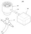
도 1은 본 발명의 일 실시예에 따른 기관절개술 튜브용 브라켓을 포함하는 튜브시스템을 나타낸 개념도이다.
도 2는 기관절개술 튜브를 나타낸 사시도이다.
도 3은 본 발명의 일 실시예에 따른 기관절개술 튜브용 브라켓을 나타낸 사시도이다.
도 4는 본 발명의 일 실시예에 따른 기관절개술 튜브용 브라켓의 단면을 나타낸 종단면도이다.
도 5는 도 3의 기관절개술 튜브용 브라켓을 위에서 바라본 모습을 나타낸 평면도이다.
도 6은 도 4의 AA'선분에 따른 단면을 나타낸 단면도이다.
도 7은 본 발명의 일 실시예에 따른 기관절개술 튜브용 브라켓이 기관절개술 튜브의 연결부에 장착되는 모습을 나타낸 종단면도이다.
도 8은 본 발명의 다른 실시예에 따른 기관절개술 튜브용 브라켓의 단면을 나타낸 종단면도이다.1 is a conceptual diagram illustrating a tube system including a bracket for a tracheostomy tube according to an embodiment of the present invention.
2 is a perspective view showing a tracheostomy tube.
Figure 3 is a perspective view showing a bracket for a tracheostomy tube according to an embodiment of the present invention.
Figure 4 is a longitudinal sectional view showing a cross section of the bracket for a tracheostomy tube according to an embodiment of the present invention.
Figure 5 is a plan view showing the top view of the bracket for the tracheostomy tube of Figure 3;
6 is a cross-sectional view taken along line AA′ of FIG. 4 .
7 is a longitudinal cross-sectional view showing a state in which the bracket for a tracheostomy tube according to an embodiment of the present invention is mounted on the connection part of the tracheostomy tube.
8 is a longitudinal sectional view showing a cross section of a bracket for a tracheostomy tube according to another embodiment of the present invention.
본 발명은 다양한 변환을 가할 수 있고 여러 가지 실시예를 가질 수 있는 바, 특정 실시예를 예시하고 상세한 설명에 상세하게 설명하고자 한다. 그러나, 이는 본 발명을 특정한 실시 형태에 대해 한정하려는 것이 아니며, 본 발명의 사상 및 기술 범위에 포함되는 모든 변환, 균등물 내지 대체물을 포함하는 것으로 이해되어야 한다. 본 발명에서 사용한 용어는 단지 특정한 실시예를 설명하기 위해 사용된 것으로, 본 발명을 한정하려는 의도가 아니다. 단수의 표현은 문맥상 명백하게 다르게 뜻하지 않는 한, 복수의 표현을 포함한다. 본 발명에서, '포함하다' 또는 '가지다' 등의 용어는 명세서 상에 기재된 특징, 숫자, 단계, 동작, 구성요소, 부품 또는 이들을 조합한 것이 존재함을 지정하려는 것이지, 하나 또는 그 이상의 다른 특징들이나 숫자, 단계, 동작, 구성요소, 부품 또는 이들을 조합한 것들의 존재 또는 부가 가능성을 미리 배제하지 않는 것으로 이해되어야 한다. 이하, 첨부된 도면을 참조하여 본 발명의 바람직한 실시예들을 상세히 설명한다. 이때, 첨부된 도면에서 동일한 구성 요소는 가능한 동일한 부호로 나타내고 있음에 유의한다. 또한, 본 발명의 요지를 흐리게 할 수 있는 공지 기능 및 구성에 대한 상세한 설명은 생략할 것이다. 마찬가지 이유로 첨부 도면에 있어서 일부 구성요소는 과장되거나 생략되거나 개략적으로 도시되었다.Since the present invention can apply various transformations and can have various embodiments, specific embodiments are illustrated and described in detail in the detailed description. However, this is not intended to limit the present invention to specific embodiments, and should be understood to include all modifications, equivalents, and substitutes included in the spirit and scope of the present invention. The terms used in the present invention are only used to describe specific embodiments, and are not intended to limit the present invention. The singular expression includes the plural expression unless the context clearly dictates otherwise. In the present invention, terms such as 'comprise' or 'have' are intended to designate that the features, numbers, steps, operations, components, parts, or combinations thereof described in the specification exist, but one or more other features It should be understood that this does not preclude the existence or addition of numbers, steps, operations, components, parts, or combinations thereof. Hereinafter, preferred embodiments of the present invention will be described in detail with reference to the accompanying drawings. In this case, it should be noted that in the accompanying drawings, the same components are denoted by the same reference numerals as much as possible. In addition, detailed descriptions of well-known functions and configurations that may obscure the gist of the present invention will be omitted. For the same reason, some components are exaggerated, omitted, or schematically illustrated in the accompanying drawings.
이하, 첨부된 도면들을 참조하여, 본 발명의 일 실시예에 따른 감용 장치에 대하여 상세히 설명한다.Hereinafter, with reference to the accompanying drawings, it will be described in detail with respect to the reduction device according to an embodiment of the present invention.
도 1은 본 발명의 일 실시예에 따른 기관절개술 튜브용 브라켓을 포함하는 튜브시스템을 나타낸 개념도이고, 도 2는 기관절개술 튜브를 나타낸 사시도이며, 도 3은 본 발명의 일 실시예에 따른 기관절개술 튜브용 브라켓을 나타낸 사시도이고, 도 4는 본 발명의 일 실시예에 따른 기관절개술 튜브용 브라켓의 단면을 나타낸 종단면도이며, 도 5는 도 3의 기관절개술 튜브용 브라켓을 위에서 바라본 모습을 나타낸 평면도이고, 도 6은 도 4의 AA'선분에 따른 단면을 나타낸 단면도이며, 도 7은 본 발명의 일 실시예에 따른 기관절개술 튜브용 브라켓이 기관절개술 튜브의 연결부에 장착되는 모습을 나타낸 종단면도이다.1 is a conceptual view showing a tube system including a bracket for a tracheostomy tube according to an embodiment of the present invention, Figure 2 is a perspective view showing a tracheostomy tube, Figure 3 is a tracheostomy according to an embodiment of the present invention A perspective view showing a bracket for a tube, FIG. 4 is a longitudinal cross-sectional view showing a cross section of a bracket for a tracheostomy tube according to an embodiment of the present invention, and FIG. 5 is a plan view showing a view from above of the bracket for a tracheostomy tube of FIG. 6 is a cross-sectional view taken along line AA' of FIG. 4, and FIG. 7 is a longitudinal cross-sectional view showing that the bracket for a tracheostomy tube according to an embodiment of the present invention is mounted on the connection part of the tracheostomy tube. .
이하, 도 1 및 도 2를 참조하여, 본 발명의 일 실시예에 따른 기관절개술 튜브용 브라켓(100)(이하, 브라켓(100)이라 지칭한다.)을 포함하는 튜브시스템(1000)에 대하여 설명한다. 본 발명의 일 실시예에 따른 튜브시스템(1000)은 기관절개술 튜브(10), 브라켓(100), 공기청정기(200)를 포함한다.Hereinafter, a
기관절개술 튜브(10)는 튜브(1), 연결부(2), 연통홀(3), 넥플레이트(4)를 포함한다. 튜브(1)는 내부에 공기 등의 유체가 유동할 수 있도록 배관 형상으로 형성되며, 만곡이 가능하도록 유연한 소재로 형성된다. 튜브(1)의 하단은 환자의 목에 절개된 부분을 통하여 기관에 삽입될 수 있다. 튜브(1)의 하단에는 커프(cuff)(미도시)와 같은 부피체가 배치될 수도 있다.The
튜브(1)의 상단부에는 연결부(2)가 배치된다. 연결부(2)는 원통형 형상일 수 있으며, 이하에서 설명할 브라켓(100)의 커넥터(120)에 삽입될 수 있다. 연결부(2)에는 연통홀(3)이 형성된다. 연통홀(3)은 튜브(1)의 내부와 외기를 연통시킬 수 있다. 외기는 연결부(2)의 연통홀(3)을 통해 유입되어 튜브(1)에서 유동될 수 있다.At the upper end of the
연결부(2)의 하단에는 넥플레이트(4)가 고정된다. 넥플레이트(4)는 튜브 또는 연통홀(3)에서 유동하는 공기의 유동방향과 수직하는 방향으로 연장되어 형성될 수 있다. 즉, 넥플레이트(4)는 연결부(2)를 기준으로 좌우로 연장되어 날개형상으로 형성될 수 있다. 넥플레이트(4)는 환자의 목 주위 표면에 접촉된 상태로, 연결부(2)를 지지할 수 있다. 넥플레이트(4)는 연결부(2)가 환자의 기관 내부로 삽입되는 것을 방지할 수 있다.The
브라켓(100)은 기관절개술 튜브(10)에 장착되거나 기관절개술 튜브(10)로부터 해제될 수 있다. 브라켓(100)은 기관절개술 튜브(10)의 연결부(2)에 장착될 수 있다. 브라켓(100)은 공기청정기(200)로부터 정화된 공기를 공급받을 수 있다.The
공기청정기(200)는 외부의 오염된 공기를 정화시켜 배출시킨다. 공기청정기(200)는 내부 공간에 고정식으로 설치되는 고정식 공기청정기(200)일 수 있으며, 바람직하게는 휴대가 가능한 휴대용 공기청정기(200)일 수도 있다.The
휴대용 공기 청정기는 배터리 내지 축전지 등을 이용하여 별도의 외부 전원 연결 없이도 일정 시간동안 공기를 정화시킬 수 있는 공기청정기(200)를 의미한다. 휴대용 공기청정기(200)를 채택할 경우, 환자의 이동이 자유로워 공간적인 제약이 크게 해소될 수 있다는 장점이 있다. 상기의 공기청정기(200)의 종류에 대한 설명은 예시에 불과하며, 공기청정기(200)의 종류는 이에 제한되지 않는다.The portable air purifier refers to the
공기청정기(200)는 공급배관(210)을 포함한다. 공급배관(210)은 공기청정기(200)와 브라켓(100)을 연결한다. 공급배관(210)은 한 개가 구비될 수 있고, 경우에 따라 두 개 이상이 구비될 수도 있다. 공기청정기(200)로부터 배출되는 정화된 공기는 공급배관(210)을 통해 브라켓(100)으로 공급된다.The
이하, 도 3 내지 도 7을 참조하여, 본 발명의 일 실시예에 브라켓(100)에 대하여 상세히 설명한다. 본 발명의 일 실시예에 따른 브라켓(100)은 메인바디(110), 커넥터(120)를 포함한다.Hereinafter, with reference to FIGS. 3 to 7, the
메인바디(110)는 메인홀(130), 유입구(140), 제1토출구(150), 제2토출구(160)를 포함한다. 메인바디(110)의 외형은 대략 원통형으로 형성될 수 있으나, 메인바디(110)의 외형은 이에 한정되지 않는다. 메인바디(110)의 내부에는 내부공간(S)이 형성된다. 내부공간(S)에서는 공기 등의 유체가 유동할 수 있다.The
메인바디(110)에는 메인홀(130)이 형성된다. 메인홀(130)은 메인바디(110)의 대략 중앙부에서 상하 방향으로 관통하도록 형성된다. 메인홀(130)의 상부는 하측으로 갈수록 지름이 좁아지도록 형성되고, 메인홀(130)의 하부는 하측으로 갈수록 지름이 일정하게 유지되도록 형성될 수 있다. 메인홀(130)이 형성됨에 따라, 메인바디(110)의 외형은 위에서 바라볼 때 대략 도넛형일 수도 있다. 이 때, 메인홀(130)을 형성하고 메인홀(130)과 내부공간(S) 사이의 벽을 메인바디(110)의 내측벽(IW)이라 지칭한다.A
메인바디(110)에는 유입구(140)가 형성된다. 유입구(140)는 메인바디(110)의 측부에 형성될 수 있다. 즉, 유입구(140)는 메인바디(110)의 내부공간(S)을 기준으로 메인홀(130)의 반대측에 형성될 수 있다. 그러나, 유입구(140)의 형성 위치는 이에 한정되는 것이 아니며, 경우에 따라, 메인바디(110)의 상측부나 하측부에도 형성될 수 있다.An
유입구(140)는 내부공간(S)과 연통되도록 형성된다. 유입구(140)를 통해서 공기청정기(200)로부터 배출된 정화된 공기가 내부공간(S)으로 유입될 수 있다. 유입구(140)는 공기청정기(200)의 공급배관(210)과 연결될 수 있다. 이 경우, 정화된 공기는 공급배관(210)을 거쳐 유입구(140)를 통해 내부공간(S)에 공급될 수 있다.The
첨부된 도면에서는 유입구(140) 및 공급배관(210)이 각각 한 개씩 구비된 것으로 도시되어 있으나, 유입구(140) 및 공급배관(210)의 개수는 이에 한정되지 않는다. 경우에 따라서, 유입구(140) 또는 공급배관(210)이 복수 개로 구비될 수 있다. 예를 들어 메인바디(110)에 유입구(140)가 복수 개 구비되고, 이에 따라 공급배관(210)도 각각의 유입구(140)에 모두 연결될 수 있다. 이 때, 공급배관(210)은 유입구(140)의 개수와 대응되는 개수로 구비될 수 있다.In the accompanying drawings, it is illustrated that the
상기와는 달리, 공급배관(210)의 입구의 개수는 유입구(140)의 개수보다 적으나, 공급배관(210)의 출구의 개수는 유입구(140)의 개수와 대응되도록 구비되어, 공급배관(210)이 분지관의 형태로 구성될 수도 있다. 이 경우, 각각의 공급배관(210)에서의 공기 유동은 각각 독립적으로 제어될 수 있다.Unlike the above, the number of inlets of the
또한, 첨부된 도면에는 공기청정기(200)가 브라켓(100)과 일대일 대응되는 것으로 도시되어 있으나, 공기청정기(200) 또는 브라켓(100)의 개수는 이에 한정되지 않는다. 예를들어, 하나의 공기청정기(200)가 복수 개의 브라켓(100)에 연결될 수 있고, 반대로, 하나의 브라켓(100)에 복수 개의 공기청정기(200)가 연결될 수도 있다.In addition, although the accompanying drawings show that the
메인바디(110)의 상부에는 제1토출구(150)가 형성된다. 이 경우, 제1토출구(150)는 메인바디(110)의 내측벽(IW)에 형성될 수 있다. 제1토출구(150)는 적어도 한 개 이상 구비될 수 있고, 복수 개가 구비될 수도 있다. 제1토출구(150)는 메인바디(110)의 상부로부터 적어도 일부분이 메인홀(130)을 따라 하측으로 연장되어 형성될 수 있다. 이 경우, 제1토출구(150)의 적어도 일부분이 메인바디(110)의 내측벽(IW)을 따라 하측으로 연장되어 형성될 수 있다.A
제1토출구(150)는 내부공간(S)과 연통되도록 형성된다. 내부공간(S)에 유입된 공기는 제1토출구(150)를 통해 외부로 토출될 수 있다. 또는, 내부공간(S)에 유입된 공기는 제1토출구(150)를 통해 메인홀(130)을 거쳐서 외부로 토출될 수 있다.The
이 때, 제1토출구(150)를 통해서 토출되는 공기는 상측으로 유동하는 공기의 흐름인 상승기류를 형성한다. 에어커튼(air curtain)은 공기의 힘을 이용하여 공기 중에 장벽을 만들어 내외부를 차단하는 것을 의미한다. 상승기류는 에어커튼(air curtain)을 형성하여 오염 물질 등의 외부 물질이 메인홀(130)로 유입되는 것을 차단할 수 있다.At this time, the air discharged through the
제1토출구(150)는 복수 개가 구비되어 위에서 바라볼 때 나선형으로 형성될 수 있다. 이 때, 각각의 제1토출구(150)는 나선형의 기다란 슬릿 형상으로 형성될 수 있다. 위에서 바라볼 때 복수 개의 제1토출구(150)는 각각, 상측으로 갈수록 시계 방향 또는 반시계 방향으로 치우쳐지도록 형성될 수 있다.A plurality of
이 같은 이유로, 어느 하나의 제1토출구(150)에 있어서, 제1토출구(150)의 하측 부분에서의 공기 유동 방향과 상측 부분에서의 공기 유동 방향이 서로 어긋나도록 형성될 수 있다.For this reason, in any one of the
제1토출구(150)는 베인부(151)와 볼록부(152)를 포함할 수 있다. 제1토출구(150)는 메인바디(110)의 내측벽(IW)에서 내부공간(S)과 메인홀(130)을 연통시키도록 형성될 수 있다. 즉, 제1토출구(150)는 메인바디(110)의 내측벽(IW)을 관통하여 형성되는데, 이 때, 각각의 제1토출구(150)의 상기 관통 방향이 시계 방향 또는 반시계 방향 중 어느 한 쪽으로 모두 치우쳐지도록 형성될 수 있다. 이로 인하여, 제1토출구(150)를 형성하는 메인바디(110)의 내측벽(IW)의 상기 관통 부분에는 단면이 뾰족한 부분이 형성될 수 있다. 상기 뾰족한 부분이 베인부(151)이다. 베인부(151)는 내부공간(S)에서 제1토출구(150)를 통해 토출되는 공기의 방향을 특정 방향으로 가이드할 수 있다.The
베인부(151)와 마주보는 메인바디(110)의 내측벽(IW) 부분에는 볼록부(152)가 형성될 수 있다. 볼록부(152)는 단면이 곡선으로 볼록하게 형성된다. 볼록부(152)에서는 코안다 효과(coanda effect)에 의해서 토출되는 공기가 메인바디(110)의 내측벽(IW)에 달라붙어서 유동하게 된다. 이 경우, 베인부(151)에서 특정 방향으로 가이드된 공기의 유동이 상기 특정 방향으로 더욱 더 안내될 수 있다는 효과가 있다.A
제1토출구(150)가 복수 개 및 나선형으로 형성될 경우, 제1토출구(150)를 통해서 형성된 상승기류는 소용돌이를 형성할 수 있다. 이 경우, 상승기류가 형성하는 에어커튼(air curtain)은 소용돌이에 의해서 더욱 더 강하게 형성될 수 있고, 이로 인하여 외부 물질이 메인홀(130)로 유입되는 것을 더욱 더 강력하게 차단시킬 수 있게 된다.When a plurality of
메인바디(110)에는 제2토출구(160)가 형성된다. 제2토출구(160)는 메인바디(110)의 내측벽(IW)에 형성될 수 있다. 제2토출구(160)는 제1토출구(150)의 하측에 위치할 수 있다. 제2토출구(160)는 내부공간(S)과 연통되도록 형성된다. 제2토출구(160)는 적어도 한 개 이상 구비된다. 제2토출구(160)가 한 개가 구비될 경우, 내측벽(IW)의 둘레를 따라 길게 연장되어 형성될 수도 있다. 제2토출구(160)가 두 개 이상 복수 개로 구비될 경우, 복수 개의 제2토출구(160)는 내측벽(IW)의 둘레를 따라 일정 간격으로 배치될 수 있다.A
내부공간(S)의 공기는 제2토출구(160)를 통해 메인홀(130)로 토출된다. 제2토출구(160)를 통해 메인홀(130)로 토출된 공기는 기관절개술 튜브(10)의 튜브로 유입되어 환자의 기관에 공급될 수 있다. 제2토출구(160)의 전체 유동단면적(공기 유동방향의 횡단면적)은 제1토출구(150)의 전체 유동단면적보다 크게 형성될 수 있다. 이 경우, 베르누이 방정식(Bernoulli's equation)에 따라, 제2토출구(160)에서의 유동 속도는 제1토출구(150)에서의 유동 속도보다 낮게 형성된다. 이로 인하여, 제2토출구(160)를 통해 토출된 공기는 비교적 낮은 속도로 대략 정적인 상태로 환자의 기관에 안정적으로 공급될 수 있다.The air in the inner space S is discharged to the
커넥터(120)는 메인바디(110)의 하측에 배치된다. 커넥터(120)는 메인바디(110)와 일체로 형성될 수 있으며, 메인바디(110)와 별개로 형성되어 메인바디(110)에 결합될 수도 있다. 커넥터(120)의 중앙에는 메인홀(130)이 형성된다. 커넥터(120)에 형성된 메인홀(130)은 메인바디(110)에 형성된 메인홀(130)이 연장된 것이다. 즉, 메인홀(130)은 메인바디(110)와 커넥터(120)를 각각 상하로 관통하여 서로 연속적으로 형성된 홀을 지칭하는 것이다.The
커넥터(120)에는 기관절개술 튜브(10)의 연결부(2)가 삽입될 수 있다. 연결부(2)는 메인홀(130)에 삽입될 수 있다. 커넥터(120)의 메인홀(130) 측 내벽에는 쿠션부(170)가 배치될 수 있다. 쿠션부(170)는 솜이나 메모리폼과 같은 쿠션 재질로 이루어질 수 있으며, 고무와 같이 탄성이 강한 소재로 형성될 수도 있다. 쿠션부(170)의 재질은 변형이 가능하고 복원력을 갖는 소재라면 모두 가능하다.A
커넥터(120)의 메인홀(130) 내경(D1)은 기관절개술 튜브(10)의 연결부(2) 외경(D2)보다 크게 형성된다(도 7(a)). 이에 따라, 연결부(2)가 커넥터(120)의 메인홀(130)에 삽입될 수 있다. 쿠션부(170)의 내경(D2)는 연결부(2)의 외경(D3)보다 작게 형성된다. 이 경우, 연결부(2)가 커넥터(120)의 메인홀(130)에 삽입되면서 쿠션부(170)를 압축 변형시키고, 쿠션부(170)는 연결부(2)의 표면에 복원력을 가한다. 쿠션부(170)의 복원력은 연결부(2)로의 수직항력으로 작용하여, 쿠션부(170)가 연결부(2)를 지지할 수 있게 된다(도 7(b)).The inner diameter D1 of the
즉, 기관절개술 튜브(10)의 연결부(2)는 쿠션부(170)에 억지 끼움 결합된다. 쿠션부(170)의 복원력의 크기는 쿠션부(170)의 재질이나, 내경(D2)에 따라서 달라질 수 있다. 쿠션부(170)의 복원력의 크기는 상황에 맞게 적절하게 설계될 수 있다. 예를 들어, 쿠션부(170)의 복원력은, 바람직하게는, 연결부(2)와 쿠션부(170) 간의 결합 및 해제가 용이하면서도, 환자의 일상적인 활동에서 연결부(2)가 쿠션부(170)로부터 이탈되지 않는 정도로 설계될 수 있다.That is, the
쿠션부(170)에 의해서, 기관절개술 튜브(10)의 연결부(2)가 커넥터(120)에 용이하게 삽입될 수 있고, 연결부(2)가 쿠션부(170)에 의해서 안정적으로 고정될 수 있다는 장점이 있다. 또한, 쿠션부(170)에 의해 커넥터(120)로부터 연결부(2)를 해제하는 것이 용이하며, 쿠션부(170)는 변형이 자유로우므로 커넥터(120)에 다양한 사이즈의 연결부(2)가 삽입될 수 있다는 장점도 있다.By the
도 8은 본 발명의 다른 실시예에 따른 기관절개술 튜브용 브라켓의 단면을 나타낸 종단면도이다.8 is a longitudinal sectional view showing a cross section of a bracket for a tracheostomy tube according to another embodiment of the present invention.
이하, 도 8을 참조하여, 본 발명의 다른 실시예에 따른 기관절개술 튜브(10)용 브라켓(100)에 대하여 상세히 설명한다. 본 발명의 다른 실시예에 따른 브라켓(100)은 격벽(180)을 더 포함한다. 이하, 본 발명의 일 실시예에 따른 브라켓(100)과 동일한 부분에 대하여는 중복되는 설명이므로 이를 생략한다.Hereinafter, with reference to FIG. 8, the
격벽(180)은 메인바디(110)의 내부공간(S)에 배치된다. 격벽(180)은 내부공간(S)을 제1내부공간(S1)과 제2내부공간(S2)으로 분리한다. 격벽(180)은 제1내부공간(S1)과 제2내부공간(S2)을 상하로 구분하도록 배치될 수 있다. 이 경우, 제1내부공간(S1)이 형성된 메인바디(110) 부분을 어퍼바디(111)라 하고, 제2내부공간(S2)이 형성된 메인바디(110) 부분을 로어바디(112)라 한다. 어퍼바디(111)에는 제1토출구(150)가 형성되고, 제1토출구(150)는 제1내부공간(S1)과 연통될 수 있다. 로어바디(112)에는 제2토출구(160)가 형성되고, 제2토출구(160)는 제2내부공간(S2)과 연통될 수 있다.The
이 때, 유입구(140)는 제1유입구(141)와 제2유입구(142)로 구비될 수 있다. 제1유입구(141)는 제1내부공간(S1)과 연통되고, 제2유입구(142)는 제2내부공간(S2)과 연통될 수 있다. 제1유입구(141)를 통해 유입된 공기는 제1내부공간(S1)을 거쳐 제1토출구(150)를 통해 토출될 수 있다. 제2유입구(142)를 통해 유입된 공기는 제2내부공간(S2)을 거쳐 제2토출구(160)를 통해 토출될 수 있다.In this case, the
이 경우, 공기청정기(200)로부터 토출된 정화된 공기를 공급하는 공급배관(210)은 출구가 분지되어 제1유입구(141)와 제2유입구(142)에 각각 연결될 수 있다. 또는, 공급배관(210)이 두 개의 유입구(141, 142)와 대응되도록 별도의 두개의 배관으로 구비되고, 공기청정기(200)로부터 각각 독립적으로 정화된 공기를 공급받아, 제1유입구(141)와 제2유입구(142)에 각각 독립적으로 공기를 공급할 수도 있다. 이 경우, 제1토출구(150)와 제2토출구(160)를 통해 토출되는 공기의 유동량을 각각 독립적으로 조절할 수도 있다는 장점이 있다.In this case, the
이상, 본 발명의 일 실시예에 대하여 설명하였으나, 해당 기술 분야에서 통상의 지식을 가진 자라면 특허청구범위에 기재된 본 발명의 사상으로부터 벗어나지 않는 범위 내에서, 구성 요소의 부가, 변경, 삭제 또는 추가 등에 의해 본 발명을 다양하게 수정 및 변경시킬 수 있을 것이며, 이러한 수정, 변경 또한 본 발명의 권리범위 내에 포함된다고 할 것이다.In the above, an embodiment of the present invention has been described, but those of ordinary skill in the art can add, change, delete or add components within the scope that does not depart from the spirit of the present invention described in the claims. The present invention may be variously modified and changed by, etc., and it will be said that such modifications and changes are also included within the scope of the present invention.
10 : 기관절개술 튜브
1 : 튜브2 : 연결부
3 : 연통홀4 : 넥플레이트
100 : 브라켓
110 : 메인바디
111 : 어퍼바디112 : 로어바디
120 : 커넥터
130 : 메인홀
140 : 유입구
141 : 제1유입구142 : 제2유입구
150 : 제1토출구
151 : 베인부152 : 볼록부
160 : 제2토출구
170 : 쿠션부
180 : 격벽
200 : 공기청정기
210 : 공급배관
1000 : 튜브시스템
S : 공동부
S1 : 제1공동부S2 : 제2공동부10: tracheostomy tube
1: tube 2: connection part
3: communication hole 4: neck plate
100: bracket
110: main body
111: upper body 112: lower body
120: connector
130: main hall
140: inlet
141: first inlet 142: second inlet
150: first outlet
151: vane portion 152: convex portion
160: second outlet
170: cushion part
180: bulkhead
200: air purifier
210: supply pipe
1000: tube system
S: cavity
S1: first cavity S2: second cavity
Claims (5)
Translated fromKorean상기 메인바디의 하측에 배치되고, 기관절개술 튜브의 연결부가 삽입될 수 있는 커넥터;
상기 메인바디 및 상기 커넥터를 상하로 연속하여 관통하도록 형성되는 메인홀;
상기 메인바디에 상기 내부공간과 연통되도록 형성되며, 공기청정기로부터 공급되는 정화된 공기가 유입되는 유입구;
상기 메인바디의 상부에 상기 내부공간과 연통되도록 형성되는 적어도 한 개 이상의 제1토출구;
상기 메인바디에 상기 내부공간과 상기 메인홀이 연통되도록 형성되는 적어도 한 개 이상의 제2토출구; 및
상기 커넥터의 상기 메인홀 내벽에 배치되는 탄성재질의 쿠션부를 포함하고,
상기 메인홀의 내경은 상기 기관절개술 튜브의 상기 연결부의 외경보다 크며,
상기 쿠션부의 내경은 상기 기관절개술 튜브의 상기 연결부의 외경보다 작은 기관절개술 튜브용 브라켓.a main body having an internal space;
a connector disposed on the lower side of the main body and into which the connection part of the tracheostomy tube can be inserted;
a main hole formed to vertically penetrate the main body and the connector;
an inlet formed in the main body to communicate with the inner space, through which purified air supplied from the air purifier is introduced;
at least one first outlet formed on an upper portion of the main body to communicate with the inner space;
at least one second discharge port formed in the main body so that the inner space and the main hole communicate with each other; and
and a cushion part of an elastic material disposed on the inner wall of the main hole of the connector,
The inner diameter of the main hole is greater than the outer diameter of the connection part of the tracheostomy tube,
The inner diameter of the cushion portion is smaller than the outer diameter of the connection portion of the tracheostomy tube bracket.
상기 제1토출구는
상기 메인바디의 상부에서 상기 메인홀을 향해 연장되어 형성되고,
복수 개가 구비되어 위에서 바라볼 때 나선형으로 형성되는 기관절개술 튜브용 브라켓.According to claim 1,
The first outlet is
It is formed extending from the upper part of the main body toward the main hole,
A bracket for a tracheostomy tube that is provided in plurality and is spirally formed when viewed from above.
상기 메인바디의 내부에 배치되고 상기 내부공간을 제1내부공간 및 제2내부공간으로 분리하는 격벽을 더 포함하고,
상기 제1내부공간은 상기 제1토출구와 연통되며,
상기 제2내부공간은 상기 제2토출구와 연통되고,
상기 유입구는 상기 제1내부공간과 연통되는 제1유입구, 및 상기 제2내부공간과 연통되는 제2유입구로 구비되는 기관절개술 튜브용 브라켓.According to claim 1,
It is disposed inside the main body and further comprises a partition wall separating the inner space into a first inner space and a second inner space,
The first inner space communicates with the first outlet,
The second inner space communicates with the second outlet,
The inlet is a bracket for a tracheostomy tube provided with a first inlet communicating with the first internal space, and a second inlet communicating with the second internal space.
상기 기관절개술 튜브용 브라켓이 장착되는 상기 기관절개술 튜브; 및
상기 기관절개술 튜브용 브라켓에 정화된 공기를 공급하는 공기청정기를 포함하는 튜브시스템.The bracket for the tracheostomy tube according to any one of claims 1, 2 and 4;
the tracheostomy tube to which the bracket for the tracheostomy tube is mounted; and
A tube system including an air purifier for supplying purified air to the bracket for the tracheostomy tube.
Priority Applications (2)
| Application Number | Priority Date | Filing Date | Title |
|---|---|---|---|
| KR1020210161405AKR102365929B1 (en) | 2021-11-22 | 2021-11-22 | bracket for tracheostomy tube and tube system including the same |
| PCT/KR2022/008529WO2023090558A1 (en) | 2021-11-22 | 2022-06-16 | Bracket for tracheostomy tube and tube system comprising same |
Applications Claiming Priority (1)
| Application Number | Priority Date | Filing Date | Title |
|---|---|---|---|
| KR1020210161405AKR102365929B1 (en) | 2021-11-22 | 2021-11-22 | bracket for tracheostomy tube and tube system including the same |
Publications (1)
| Publication Number | Publication Date |
|---|---|
| KR102365929B1true KR102365929B1 (en) | 2022-02-23 |
Family
ID=80495625
Family Applications (1)
| Application Number | Title | Priority Date | Filing Date |
|---|---|---|---|
| KR1020210161405AActiveKR102365929B1 (en) | 2021-11-22 | 2021-11-22 | bracket for tracheostomy tube and tube system including the same |
Country Status (2)
| Country | Link |
|---|---|
| KR (1) | KR102365929B1 (en) |
| WO (1) | WO2023090558A1 (en) |
Cited By (1)
| Publication number | Priority date | Publication date | Assignee | Title |
|---|---|---|---|---|
| WO2023090558A1 (en)* | 2021-11-22 | 2023-05-25 | 박종우 | Bracket for tracheostomy tube and tube system comprising same |
Citations (5)
| Publication number | Priority date | Publication date | Assignee | Title |
|---|---|---|---|---|
| KR200320969Y1 (en) | 2003-04-16 | 2003-07-22 | 이병호 | Tracheotomy tube |
| JP2010535085A (en)* | 2007-07-30 | 2010-11-18 | パッシィ−ミューア,インコーポレイテッド | Tracheostomy valve and related methods |
| JP2016527059A (en)* | 2013-08-08 | 2016-09-08 | ベイポサーム, インコーポレイティド | Respiratory therapy condensation adapter |
| KR101723969B1 (en)* | 2016-03-29 | 2017-04-06 | (주)엘메카 | Catheter Guide Structure |
| KR101955699B1 (en)* | 2018-09-20 | 2019-03-08 | 김옥련 | Device for assisting vocalization of Tracheostomy tube |
Family Cites Families (2)
| Publication number | Priority date | Publication date | Assignee | Title |
|---|---|---|---|---|
| US7600515B2 (en)* | 2005-09-28 | 2009-10-13 | Nellcor Puritan Bennett Llc | Tracheostomy tube combination radial snap and bayonet cannula connector |
| KR102365929B1 (en)* | 2021-11-22 | 2022-02-23 | 박종우 | bracket for tracheostomy tube and tube system including the same |
- 2021
- 2021-11-22KRKR1020210161405Apatent/KR102365929B1/enactiveActive
- 2022
- 2022-06-16WOPCT/KR2022/008529patent/WO2023090558A1/ennot_activeCeased
Patent Citations (5)
| Publication number | Priority date | Publication date | Assignee | Title |
|---|---|---|---|---|
| KR200320969Y1 (en) | 2003-04-16 | 2003-07-22 | 이병호 | Tracheotomy tube |
| JP2010535085A (en)* | 2007-07-30 | 2010-11-18 | パッシィ−ミューア,インコーポレイテッド | Tracheostomy valve and related methods |
| JP2016527059A (en)* | 2013-08-08 | 2016-09-08 | ベイポサーム, インコーポレイティド | Respiratory therapy condensation adapter |
| KR101723969B1 (en)* | 2016-03-29 | 2017-04-06 | (주)엘메카 | Catheter Guide Structure |
| KR101955699B1 (en)* | 2018-09-20 | 2019-03-08 | 김옥련 | Device for assisting vocalization of Tracheostomy tube |
Cited By (1)
| Publication number | Priority date | Publication date | Assignee | Title |
|---|---|---|---|---|
| WO2023090558A1 (en)* | 2021-11-22 | 2023-05-25 | 박종우 | Bracket for tracheostomy tube and tube system comprising same |
Also Published As
| Publication number | Publication date |
|---|---|
| WO2023090558A1 (en) | 2023-05-25 |
Similar Documents
| Publication | Publication Date | Title |
|---|---|---|
| US20210386949A1 (en) | Secretion clearing patient airway management system | |
| US6561191B1 (en) | Mask and a vent assembly therefor | |
| US8371304B2 (en) | Continuous positive airway pressure device and method | |
| AU712236B2 (en) | A mask and a vent assembly therefor | |
| US8517022B2 (en) | Minimally invasive nasal cannula | |
| CN104902948B (en) | Quiet nasal cannula | |
| US20230347091A1 (en) | Universal Medical Gas Delivery System | |
| US20160296721A1 (en) | High flow therapy artificial airway interfaces and related methods | |
| CN102413861B (en) | System and method for circuits to allow cpap to provide zero pressure | |
| SE462614B (en) | DEVICE TO GENERATE CONTINUOUS POSITIVE AIR PRESSURE IN SPONTANEOUS THROUGH EJECTOR EFFECTS | |
| CN102245251A (en) | Exhaust vent configuration | |
| US20160074610A1 (en) | Universal medical gas delivery system | |
| JPH09108354A (en) | Trachea system | |
| CN101474445A (en) | Continuous positive airway pressure device | |
| CN104968386A (en) | multifunctional oxygen mask | |
| US20180369526A1 (en) | Airway Suction Inlet Port | |
| ES3007813T3 (en) | Respiratory apparatus with noise-damping member | |
| HUP0003171A2 (en) | Endotracheal or tracheotomy tube | |
| KR102365929B1 (en) | bracket for tracheostomy tube and tube system including the same | |
| ES2768383T3 (en) | Apparatus for controlling the flow of oxygen and / or air to nasal cannulas | |
| KR20200053856A (en) | Intubation tube having self cleaning property | |
| CN217246007U (en) | Ventilation treatment equipment and adapter thereof | |
| CN101648042A (en) | Tracheal cannula with function of automatically eliminating phlegm and automatic phlegm eliminating system using same | |
| US20120204876A1 (en) | Fluid flow control apparatus and method and patient interface device employing same | |
| AU724360B2 (en) | A mask and a vent assembly therefor |
Legal Events
| Date | Code | Title | Description |
|---|---|---|---|
| PA0109 | Patent application | Patent event code:PA01091R01D Comment text:Patent Application Patent event date:20211122 | |
| PA0201 | Request for examination | ||
| PA0302 | Request for accelerated examination | Patent event date:20211209 Patent event code:PA03022R01D Comment text:Request for Accelerated Examination Patent event date:20211122 Patent event code:PA03021R01I Comment text:Patent Application | |
| E902 | Notification of reason for refusal | ||
| PE0902 | Notice of grounds for rejection | Comment text:Notification of reason for refusal Patent event date:20220117 Patent event code:PE09021S01D | |
| E701 | Decision to grant or registration of patent right | ||
| PE0701 | Decision of registration | Patent event code:PE07011S01D Comment text:Decision to Grant Registration Patent event date:20220214 | |
| GRNT | Written decision to grant | ||
| PR0701 | Registration of establishment | Comment text:Registration of Establishment Patent event date:20220217 Patent event code:PR07011E01D | |
| PR1002 | Payment of registration fee | Payment date:20220217 End annual number:3 Start annual number:1 | |
| PG1601 | Publication of registration | ||
| PR1001 | Payment of annual fee | Payment date:20241120 Start annual number:4 End annual number:4 |