KR102364490B1 - Untrasound dianognosis apparatus, method and computer-readable storage medium - Google Patents
Untrasound dianognosis apparatus, method and computer-readable storage mediumDownload PDFInfo
- Publication number
- KR102364490B1 KR102364490B1KR1020140180493AKR20140180493AKR102364490B1KR 102364490 B1KR102364490 B1KR 102364490B1KR 1020140180493 AKR1020140180493 AKR 1020140180493AKR 20140180493 AKR20140180493 AKR 20140180493AKR 102364490 B1KR102364490 B1KR 102364490B1
- Authority
- KR
- South Korea
- Prior art keywords
- nodes
- ultrasound
- viewpoint
- image
- node
- Prior art date
- Legal status (The legal status is an assumption and is not a legal conclusion. Google has not performed a legal analysis and makes no representation as to the accuracy of the status listed.)
- Active
Links
Images


Classifications
- A—HUMAN NECESSITIES
- A61—MEDICAL OR VETERINARY SCIENCE; HYGIENE
- A61B—DIAGNOSIS; SURGERY; IDENTIFICATION
- A61B8/00—Diagnosis using ultrasonic, sonic or infrasonic waves
- A61B8/46—Ultrasonic, sonic or infrasonic diagnostic devices with special arrangements for interfacing with the operator or the patient
- A61B8/467—Ultrasonic, sonic or infrasonic diagnostic devices with special arrangements for interfacing with the operator or the patient characterised by special input means
- G—PHYSICS
- G06—COMPUTING OR CALCULATING; COUNTING
- G06T—IMAGE DATA PROCESSING OR GENERATION, IN GENERAL
- G06T7/00—Image analysis
- A—HUMAN NECESSITIES
- A61—MEDICAL OR VETERINARY SCIENCE; HYGIENE
- A61B—DIAGNOSIS; SURGERY; IDENTIFICATION
- A61B1/00—Instruments for performing medical examinations of the interior of cavities or tubes of the body by visual or photographical inspection, e.g. endoscopes; Illuminating arrangements therefor
- A—HUMAN NECESSITIES
- A61—MEDICAL OR VETERINARY SCIENCE; HYGIENE
- A61B—DIAGNOSIS; SURGERY; IDENTIFICATION
- A61B8/00—Diagnosis using ultrasonic, sonic or infrasonic waves
- A61B8/08—Clinical applications
- A61B8/0833—Clinical applications involving detecting or locating foreign bodies or organic structures
- A61B8/085—Clinical applications involving detecting or locating foreign bodies or organic structures for locating body or organic structures, e.g. tumours, calculi, blood vessels, nodules
- A—HUMAN NECESSITIES
- A61—MEDICAL OR VETERINARY SCIENCE; HYGIENE
- A61B—DIAGNOSIS; SURGERY; IDENTIFICATION
- A61B8/00—Diagnosis using ultrasonic, sonic or infrasonic waves
- A61B8/08—Clinical applications
- A61B8/0891—Clinical applications for diagnosis of blood vessels
- A—HUMAN NECESSITIES
- A61—MEDICAL OR VETERINARY SCIENCE; HYGIENE
- A61B—DIAGNOSIS; SURGERY; IDENTIFICATION
- A61B8/00—Diagnosis using ultrasonic, sonic or infrasonic waves
- A61B8/13—Tomography
- A—HUMAN NECESSITIES
- A61—MEDICAL OR VETERINARY SCIENCE; HYGIENE
- A61B—DIAGNOSIS; SURGERY; IDENTIFICATION
- A61B8/00—Diagnosis using ultrasonic, sonic or infrasonic waves
- A61B8/40—Positioning of patients, e.g. means for holding or immobilising parts of the patient's body
- A—HUMAN NECESSITIES
- A61—MEDICAL OR VETERINARY SCIENCE; HYGIENE
- A61B—DIAGNOSIS; SURGERY; IDENTIFICATION
- A61B8/00—Diagnosis using ultrasonic, sonic or infrasonic waves
- A61B8/46—Ultrasonic, sonic or infrasonic diagnostic devices with special arrangements for interfacing with the operator or the patient
- A61B8/461—Displaying means of special interest
- A61B8/463—Displaying means of special interest characterised by displaying multiple images or images and diagnostic data on one display
- A—HUMAN NECESSITIES
- A61—MEDICAL OR VETERINARY SCIENCE; HYGIENE
- A61B—DIAGNOSIS; SURGERY; IDENTIFICATION
- A61B8/00—Diagnosis using ultrasonic, sonic or infrasonic waves
- A61B8/46—Ultrasonic, sonic or infrasonic diagnostic devices with special arrangements for interfacing with the operator or the patient
- A61B8/461—Displaying means of special interest
- A61B8/465—Displaying means of special interest adapted to display user selection data, e.g. icons or menus
- A—HUMAN NECESSITIES
- A61—MEDICAL OR VETERINARY SCIENCE; HYGIENE
- A61B—DIAGNOSIS; SURGERY; IDENTIFICATION
- A61B8/00—Diagnosis using ultrasonic, sonic or infrasonic waves
- A61B8/46—Ultrasonic, sonic or infrasonic diagnostic devices with special arrangements for interfacing with the operator or the patient
- A61B8/461—Displaying means of special interest
- A61B8/466—Displaying means of special interest adapted to display 3D data
- A—HUMAN NECESSITIES
- A61—MEDICAL OR VETERINARY SCIENCE; HYGIENE
- A61B—DIAGNOSIS; SURGERY; IDENTIFICATION
- A61B8/00—Diagnosis using ultrasonic, sonic or infrasonic waves
- A61B8/48—Diagnostic techniques
- A61B8/483—Diagnostic techniques involving the acquisition of a 3D volume of data
- A—HUMAN NECESSITIES
- A61—MEDICAL OR VETERINARY SCIENCE; HYGIENE
- A61B—DIAGNOSIS; SURGERY; IDENTIFICATION
- A61B8/00—Diagnosis using ultrasonic, sonic or infrasonic waves
- A61B8/52—Devices using data or image processing specially adapted for diagnosis using ultrasonic, sonic or infrasonic waves
- A61B8/5207—Devices using data or image processing specially adapted for diagnosis using ultrasonic, sonic or infrasonic waves involving processing of raw data to produce diagnostic data, e.g. for generating an image
- A—HUMAN NECESSITIES
- A61—MEDICAL OR VETERINARY SCIENCE; HYGIENE
- A61B—DIAGNOSIS; SURGERY; IDENTIFICATION
- A61B8/00—Diagnosis using ultrasonic, sonic or infrasonic waves
- A61B8/52—Devices using data or image processing specially adapted for diagnosis using ultrasonic, sonic or infrasonic waves
- A61B8/5215—Devices using data or image processing specially adapted for diagnosis using ultrasonic, sonic or infrasonic waves involving processing of medical diagnostic data
- A61B8/5223—Devices using data or image processing specially adapted for diagnosis using ultrasonic, sonic or infrasonic waves involving processing of medical diagnostic data for extracting a diagnostic or physiological parameter from medical diagnostic data
- A—HUMAN NECESSITIES
- A61—MEDICAL OR VETERINARY SCIENCE; HYGIENE
- A61B—DIAGNOSIS; SURGERY; IDENTIFICATION
- A61B8/00—Diagnosis using ultrasonic, sonic or infrasonic waves
- A61B8/52—Devices using data or image processing specially adapted for diagnosis using ultrasonic, sonic or infrasonic waves
- A61B8/5215—Devices using data or image processing specially adapted for diagnosis using ultrasonic, sonic or infrasonic waves involving processing of medical diagnostic data
- A61B8/523—Devices using data or image processing specially adapted for diagnosis using ultrasonic, sonic or infrasonic waves involving processing of medical diagnostic data for generating planar views from image data in a user selectable plane not corresponding to the acquisition plane
- A—HUMAN NECESSITIES
- A61—MEDICAL OR VETERINARY SCIENCE; HYGIENE
- A61B—DIAGNOSIS; SURGERY; IDENTIFICATION
- A61B8/00—Diagnosis using ultrasonic, sonic or infrasonic waves
- A61B8/52—Devices using data or image processing specially adapted for diagnosis using ultrasonic, sonic or infrasonic waves
- A61B8/5215—Devices using data or image processing specially adapted for diagnosis using ultrasonic, sonic or infrasonic waves involving processing of medical diagnostic data
- A61B8/5238—Devices using data or image processing specially adapted for diagnosis using ultrasonic, sonic or infrasonic waves involving processing of medical diagnostic data for combining image data of patient, e.g. merging several images from different acquisition modes into one image
- A61B8/5246—Devices using data or image processing specially adapted for diagnosis using ultrasonic, sonic or infrasonic waves involving processing of medical diagnostic data for combining image data of patient, e.g. merging several images from different acquisition modes into one image combining images from the same or different imaging techniques, e.g. color Doppler and B-mode
- G—PHYSICS
- G06—COMPUTING OR CALCULATING; COUNTING
- G06T—IMAGE DATA PROCESSING OR GENERATION, IN GENERAL
- G06T19/00—Manipulating 3D models or images for computer graphics
- G06T19/003—Navigation within 3D models or images
- G—PHYSICS
- G16—INFORMATION AND COMMUNICATION TECHNOLOGY [ICT] SPECIALLY ADAPTED FOR SPECIFIC APPLICATION FIELDS
- G16H—HEALTHCARE INFORMATICS, i.e. INFORMATION AND COMMUNICATION TECHNOLOGY [ICT] SPECIALLY ADAPTED FOR THE HANDLING OR PROCESSING OF MEDICAL OR HEALTHCARE DATA
- G16H50/00—ICT specially adapted for medical diagnosis, medical simulation or medical data mining; ICT specially adapted for detecting, monitoring or modelling epidemics or pandemics
- G16H50/30—ICT specially adapted for medical diagnosis, medical simulation or medical data mining; ICT specially adapted for detecting, monitoring or modelling epidemics or pandemics for calculating health indices; for individual health risk assessment
- A—HUMAN NECESSITIES
- A61—MEDICAL OR VETERINARY SCIENCE; HYGIENE
- A61B—DIAGNOSIS; SURGERY; IDENTIFICATION
- A61B90/00—Instruments, implements or accessories specially adapted for surgery or diagnosis and not covered by any of the groups A61B1/00 - A61B50/00, e.g. for luxation treatment or for protecting wound edges
- A61B90/36—Image-producing devices or illumination devices not otherwise provided for
- A61B2090/364—Correlation of different images or relation of image positions in respect to the body
- A61B2090/365—Correlation of different images or relation of image positions in respect to the body augmented reality, i.e. correlating a live optical image with another image
- A—HUMAN NECESSITIES
- A61—MEDICAL OR VETERINARY SCIENCE; HYGIENE
- A61B—DIAGNOSIS; SURGERY; IDENTIFICATION
- A61B8/00—Diagnosis using ultrasonic, sonic or infrasonic waves
- A61B8/48—Diagnostic techniques
- A61B8/488—Diagnostic techniques involving Doppler signals
- G—PHYSICS
- G06—COMPUTING OR CALCULATING; COUNTING
- G06T—IMAGE DATA PROCESSING OR GENERATION, IN GENERAL
- G06T2210/00—Indexing scheme for image generation or computer graphics
- G06T2210/41—Medical
Landscapes
- Health & Medical Sciences (AREA)
- Life Sciences & Earth Sciences (AREA)
- Engineering & Computer Science (AREA)
- Physics & Mathematics (AREA)
- Surgery (AREA)
- Public Health (AREA)
- Medical Informatics (AREA)
- Biomedical Technology (AREA)
- General Health & Medical Sciences (AREA)
- Pathology (AREA)
- Veterinary Medicine (AREA)
- Radiology & Medical Imaging (AREA)
- Nuclear Medicine, Radiotherapy & Molecular Imaging (AREA)
- Heart & Thoracic Surgery (AREA)
- Molecular Biology (AREA)
- Biophysics (AREA)
- Animal Behavior & Ethology (AREA)
- Computer Vision & Pattern Recognition (AREA)
- General Engineering & Computer Science (AREA)
- Vascular Medicine (AREA)
- Computer Graphics (AREA)
- Software Systems (AREA)
- General Physics & Mathematics (AREA)
- Theoretical Computer Science (AREA)
- Physiology (AREA)
- Computer Hardware Design (AREA)
- Remote Sensing (AREA)
- Radar, Positioning & Navigation (AREA)
- Human Computer Interaction (AREA)
- Optics & Photonics (AREA)
- Data Mining & Analysis (AREA)
- Databases & Information Systems (AREA)
- Epidemiology (AREA)
- Primary Health Care (AREA)
- Ultra Sonic Daignosis Equipment (AREA)
Abstract
Translated fromKoreanDescription
Translated fromKorean본원 발명은 초음파 진단장치, 그에 따른 초음파 진단 방법 및 그에 따른 컴퓨터 판독 가능한 저장매체에 관한 것이다.The present invention relates to an ultrasound diagnosis apparatus, an ultrasound diagnosis method according thereto, and a computer-readable storage medium according to the ultrasound diagnosis method.
구체적으로, 본원 발명은 초음파 진단 시 여러 부위를 관찰 할 수 있도록 하는 초음파 진단장치, 그에 따른 초음파 진단 방법 및 그에 따른 컴퓨터 판독 가능한 저장매체에 관한 것이다.More specifically, the present invention relates to an ultrasound diagnosis apparatus capable of observing various parts during ultrasound diagnosis, an ultrasound diagnosis method according thereto, and a computer-readable storage medium according thereto.
초음파진단장치는 프로브(probe)의 트랜스듀서(transducer)로부터 생성되는 초음파 신호를 대상체로 조사하고, 대상체로부터 반사된 초음파 에코 신호의 정보를 수신하여 대상체 내부의 부위에 대한 영상을 얻는다. 특히, 초음파진단장치는 대상체 내부의 관찰, 이물질 검출, 및 상해 측정 등 의학적 목적으로 사용된다. 이러한 초음파진단장치는 X선을 이용하는 진단 장치에 비하여 안정성이 높고, 실시간으로 영상의 디스플레이가 가능하며, 방사능 피폭이 없어 안전하다는 장점이 있어서 다른 화상 진단 장치와 함께 널리 이용된다.The ultrasound diagnosis apparatus irradiates an ultrasound signal generated from a transducer of a probe to an object, receives information on an ultrasound echo signal reflected from the object, and obtains an image of a region inside the object. In particular, the ultrasound diagnosis apparatus is used for medical purposes, such as observation of the inside of an object, detection of a foreign substance, and measurement of an injury. These ultrasound diagnostic devices are widely used together with other imaging diagnostic devices because they have high stability compared to diagnostic devices using X-rays, display images in real time, and are safe because there is no radiation exposure.
이와 관련하여, 의사 등의 사용자가 초음파 영상 상에서 트랙볼 등과 같은 입력 장치를 이용하여 초음파 영상의 시점을 이동하는데 있어서, 트랙볼의 이용이 익숙하지 않으면 초음파 영상 상에서 시점 이동이 쉽지 않은 문제가 있었다. 또한 트랙볼로 초음파 영상 상에서 시점 이동이 있은 후 시점이 어떠한 경로를 이용했는지 사용자가 아는데 있어서 어려움이 있었다. 따라서, 초음파 영상의 시점을 보다 용이하게 이동시킬 수 있는 초음파진단장치가 사용자에게 제공될 필요가 있다.In this regard, when a user such as a doctor moves a viewpoint of an ultrasound image by using an input device such as a trackball on an ultrasound image, it is difficult to move the viewpoint on the ultrasound image unless the user is familiar with using a trackball. In addition, it was difficult for the user to know which path the viewpoint used after the viewpoint was moved on the ultrasound image with the trackball. Accordingly, there is a need to provide a user with an ultrasound diagnosis apparatus capable of more easily moving a viewpoint of an ultrasound image.
사용자가 혈관 및 소화기와 같은 관형조직의 대상체의 초음파 진단 시에 대상체의 복수의 말단에 차례로 시점을 이동하는 과정이 필요할 수 있다. 현재의 초음파진단 장치는 트랙볼(Trackball)을 이용해서 시점을 이동시킨다. 하지만 사용자가 트랙볼로 시점을 일일이 이동시키는 데에 불편함이 있었다. 또한 사용자가 시점을 이동한 후에 지나온 경로를 알 수 없는 불편함이 있었다.When a user performs ultrasound diagnosis of an object of tubular tissue such as blood vessels and digestive organs, a process of sequentially moving a viewpoint to a plurality of ends of the object may be required. A current ultrasound diagnosis apparatus moves a viewpoint using a trackball. However, it was inconvenient for the user to move the viewpoint one by one with the trackball. In addition, there was the inconvenience of not being able to know the path the user has passed after moving the viewpoint.
본원에서는 시점 이동을 보다 용이하게 하기 위한 장치, 방법 및 컴퓨터판독 가능한 저장매체의 제공을 목적으로 한다.An object of the present application is to provide an apparatus, a method, and a computer-readable storage medium for facilitating movement of a viewpoint.
상술한 바와 같은 목적을 달성하기 위하여 본 개시의 일 실시예에 따른 초음파진단장치는 대상체를 스캔(scan)하여 획득된 초음파 데이터에 기초하여 제 1 초음파 영상을 획득하는 영상 생성부; 및 초음파 데이터에 기초하여 복수개의 노드들(nodes)을 포함하는 제 1 정보를 획득하고, 제 1 정보에 기초하여 시점을 이동하며 제 2 초음파 영상들을 획득하도록 제어하는 제어부를 포함할 수 있다.In order to achieve the above object, an ultrasound diagnosis apparatus according to an embodiment of the present disclosure includes an image generator configured to acquire a first ultrasound image based on ultrasound data obtained by scanning an object; and a controller configured to obtain first information including a plurality of nodes based on the ultrasound data, move a viewpoint based on the first information, and obtain second ultrasound images.
또한, 제어부는 제 1 정보에 근거하여 시점의 위치 및 방향 중 적어도 하나를 나타내는 제 2 정보를 획득하고, 제 1 정보 및 제 2 정보 중 적어도 하나를 제 1 초음파 영상 상에 표시한 영상을 디스플레이하는 디스플레이부를 더 포함할 수 있다.In addition, the controller obtains second information indicating at least one of a position and a direction of a viewpoint based on the first information, and displays an image in which at least one of the first information and the second information is displayed on the first ultrasound image. It may further include a display unit.
또한, 제어부는 노드들과 노드들을 연결하는 간선을 획득하고, 복수개의 노드 및 간선에 근거하여, 제 1 초음파 영상에 포함되는 구조물을 획득하도록 제어하고, 제 1 정보는 간선 및 구조물 중 적어도 하나를 포함할 수 있다.In addition, the control unit obtains nodes and trunk lines connecting the nodes, controls to obtain a structure included in the first ultrasound image based on the plurality of nodes and trunk lines, and the first information includes at least one of the trunk lines and the structures. may include
또한, 제어부는 노드들 중 적어도 두 개의 노드들의 순서를 자동으로 획득하고, 영상 생성부가 획득된 노드들의 순서로 시점을 이동하며 제 2 초음파 영상들을 획득하도록 제어할 수 있다.Also, the controller may automatically obtain the order of at least two nodes among the nodes, and control the image generator to move the viewpoint in the order of the obtained nodes to obtain the second ultrasound images.
또한, 사용자로부터 제 1 초음파 영상 상에 제 1 정보와 관련한 입력을 수신하는 입력부를 더 포함할 수 있다.The apparatus may further include an input unit configured to receive an input related to the first information on the first ultrasound image from the user.
또한, 제어부는 수신된 입력에 기초하여 노드들 및 간선 중 적어도 하나를 추가, 이동 및 삭제 중 적어도 하나를 할 수 있다.Also, the controller may add, move, and delete at least one of nodes and trunk lines based on the received input.
또한, 입력부는 사용자로부터 노드들 중 적어도 하나의 노드를 선택하는 입력을 수신하고, 제어부는 선택된 노드들에 기초하여 제 2 초음파 영상들을 자동으로 획득하도록 제어할 수 있다.Also, the input unit may receive an input for selecting at least one node from among the nodes from the user, and the control unit may control to automatically acquire second ultrasound images based on the selected nodes.
또한, 입력부는 사용자로부터 노드들 중 적어도 하나의 노드를 선택하는 입력을 수신하고, 제어부는 선택된 노드들을 제외한 노드들에 기초하여 제 2 초음파 영상들을 자동으로 획득하도록 제어할 수 있다.Also, the input unit may receive an input for selecting at least one node from among the nodes from the user, and the control unit may control to automatically acquire second ultrasound images based on nodes excluding the selected nodes.
또한, 입력부는 사용자로부터 노드들 중 적어도 두 개의 노드들의 순서에 관련된 입력을 수신하고, 제어부는 상기 수신된 노드들의 순서에 관련된 입력에 기초하여 시점을 이동하며 제 2 초음파 영상들을 획득할 수 있다.Also, the input unit may receive an input related to the order of at least two nodes among the nodes from the user, and the controller may acquire second ultrasound images while moving a viewpoint based on the received input related to the order of the nodes.
또한, 입력부는 사용자로부터 노드와 노드 사이의 이동속도에 관련된 입력을 수신하고, 제어부는 이동속도에 기초하여 시점을 이동하며 제 2 초음파 영상들을 획득하도록 제어할 수 있다.In addition, the input unit may receive an input related to a movement speed between a node and a node from a user, and the controller may control to acquire second ultrasound images while moving a viewpoint based on the movement speed.
또한, 이동속도에 관련된 입력은 노드와 노드 사이의 이동 시간을 포함할 수 있다.In addition, the input related to the movement speed may include a movement time between the node and the node.
또한, 제어부는 중심선 추출 알고리즘을 포함하는 영상처리를 이용하여 초음파 영상으로부터 노드들 및 간선을 포함하는 제 1 정보를 추출할 수 있다.Also, the controller may extract first information including nodes and trunk lines from the ultrasound image by using image processing including a centerline extraction algorithm.
또한, 제어부는 추출된 제 1 정보에 기초하여 시점을 이동하며 자동으로 제 2 초음파 영상들을 획득할 수 있다.Also, the controller may move a viewpoint based on the extracted first information and automatically acquire second ultrasound images.
또한, 제어부는 노드 및 노드 사이의 간선을 따라 시점을 이동하며 제 2 초음파 영상들을 획득하도록 제어할 수 있다.Also, the controller may control to acquire second ultrasound images while moving the viewpoint along the node and the trunk line between the nodes.
또한, 제어부는 시점이 지나간 노드들 및 간선 중 적어도 하나를 디스플레이하도록 제어할 수 있다.Also, the controller may control to display at least one of nodes and trunk lines passed by the viewpoint.
또한, 제어부는 시점이 지나간 노드들 및 간선 중 적어도 하나를 시점이 지나가지 않은 노드들 및 간선과 서로 다른 투명도, 색 및 모양 중 적어도 하나로 디스플레이하도록 제어할 수 있다.Also, the controller may control to display at least one of nodes and trunk lines passed by the viewpoint with at least one of different transparency, color, and shape from nodes and trunk lines not passed by the viewpoint.
또한, 제 2 초음파 영상들은 초음파 데이터에 기초한 가상내시경 영상을 포함할 수 있다.Also, the second ultrasound images may include a virtual endoscope image based on ultrasound data.
또한, 제 2 초음파 영상들은 2 차원 영상 및 3 차원 영상 중 적어도 하나를 포함할 수 있다.Also, the second ultrasound images may include at least one of a 2D image and a 3D image.
또한, 구조물은 트리구조의 그래프일 수 있다.Also, the structure may be a graph of a tree structure.
또한, 상술한 바와 같은 목적을 달성하기 위하여 본 개시의 다른 실시예에 따른 초음파진단장치는 대상체를 스캔(scan)하여 초음파 데이터를 획득하는 초음파 데이터 획득부; 사용자로부터 입력을 수신하는 입력부; 및 상기 초음파 데이터에 기초하여 복수개의 노드들(nodes)을 포함하는 제 1 정보를 획득하고, 제 1 정보 및 수신된 입력에 기초하여 시점을 이동하며 초음파 영상을 획득하도록 제어하는 제어부를 포함할 수 있다.Also, in order to achieve the above object, an ultrasound diagnosis apparatus according to another embodiment of the present disclosure includes an ultrasound data acquisition unit configured to scan an object to acquire ultrasound data; an input unit for receiving an input from a user; and a controller to obtain first information including a plurality of nodes based on the ultrasound data, and to move a viewpoint based on the first information and the received input to obtain an ultrasound image. there is.
또한, 상술한 바와 같은 목적을 달성하기 위하여 본 개시의 다른 실시예에 따른 초음파진단장치는 대상체를 스캔(scan)하여 초음파 데이터를 획득하는 초음파 데이터 획득부; 초음파 데이터에 기초하여 복수개의 노드들 및 간선 중 적어도 하나를 포함하는 제 1 정보를 획득하고, 제 1 정보에 기초하여 시점을 이동하도록 제어하는 제어부; 및 시점이 지나간 제 1 정보를 시점이 지나가지 않은 제 1 정보와 서로 구별되도록 디스플레이하는 디스플레이부를 포함할 수 있다.Also, in order to achieve the above object, an ultrasound diagnosis apparatus according to another embodiment of the present disclosure includes an ultrasound data acquisition unit configured to scan an object to acquire ultrasound data; a control unit configured to obtain first information including at least one of a plurality of nodes and trunk lines based on the ultrasound data, and control to move a viewpoint based on the first information; and a display unit configured to display the first information passed by the viewpoint to be distinguished from the first information not passed by the viewpoint.
또한, 상술한 바와 같은 목적을 달성하기 위하여 본 개시의 다른 실시예에 따른 초음파진단장치는 대상체를 스캔(scan)하여 제 1 초음파 영상을 획득하는 영상 생성부; 사용자로부터 입력을 수신하는 입력부; 및 상기 수신된 입력에 기초하여, 제 1 초음파 영상에 포함되는 복수개의 노드들(nodes)을 포함하는 제 1 정보를 획득하고, 수신된 입력에 기초하여 노드들의 순서를 획득하고, 노드들의 순서 및 상기 제 1 정보에 기초하여 시점을 이동하며 제 2 초음파 영상들을 획득하도록 제어하는 제어부를 포함할 수 있다.Also, in order to achieve the above object, an ultrasound diagnosis apparatus according to another embodiment of the present disclosure includes an image generator configured to scan an object to acquire a first ultrasound image; an input unit for receiving an input from a user; and, based on the received input, obtains first information including a plurality of nodes included in the first ultrasound image, obtains an order of nodes based on the received input, obtains an order of nodes, and The control unit may include a control unit that moves a viewpoint based on the first information and controls to acquire second ultrasound images.
상술한 바와 같은 목적을 달성하기 위하여 본 개시의 일 실시예에 따른 초음파 진단 방법은 대상체를 스캔(scan)하여 획득된 초음파 데이터에 기초하여 제 1 초음파 영상을 획득하는 단계; 초음파 데이터에 기초하여 복수개의 노드들(nodes)을 포함하는 제 1 정보를 획득하는 단계; 및 제 1 정보에 기초하여 시점을 이동하며 제 2 초음파 영상들을 획득하는 단계를 포함할 수 있다.In order to achieve the above object, an ultrasound diagnosis method according to an embodiment of the present disclosure includes: acquiring a first ultrasound image based on ultrasound data obtained by scanning an object; obtaining first information including a plurality of nodes based on the ultrasound data; and moving a viewpoint based on the first information and acquiring second ultrasound images.
또한, 제 1 정보에 근거하여 시점의 위치 및 방향 중 적어도 하나를 나타내는 제 2 정보를 획득하는 단계; 및 제 1 정보 및 제 2 정보 중 적어도 하나를 제 1 초음파 영상 상에 표시한 영상을 디스플레이하는 단계를 더 포함할 수 있다.The method may further include: obtaining second information indicating at least one of a position and a direction of a viewpoint based on the first information; and displaying an image in which at least one of the first information and the second information is displayed on the first ultrasound image.
또한, 노드들과 노드들을 연결하는 간선을 획득하는 단계; 및 복수개의 노드 및 간선에 근거하여, 제 1 초음파 영상에 포함되는 구조물을 획득하는 단계를 더 포함하고 제 1 정보는 간선 및 구조물 중 적어도 하나를 포함할 수 있다.In addition, the steps of: obtaining nodes and trunk lines connecting the nodes; and obtaining a structure included in the first ultrasound image based on the plurality of nodes and trunk lines, wherein the first information may include at least one of trunk lines and structures.
또한, 제 2 초음파 영상들을 획득하는 단계는, 노드들 중 적어도 두 개의 노드들의 순서를 자동으로 획득하는 단계; 및 획득된 노드들의 순서로 시점을 이동하며 제 2 초음파 영상들을 획득하는 단계를 포함할 수 있다.In addition, the acquiring of the second ultrasound images may include: automatically acquiring an order of at least two nodes among the nodes; and moving the viewpoint in the order of the acquired nodes and acquiring second ultrasound images.
또한, 사용자로부터 제 1 초음파 영상 상에 제 1 정보와 관련한 입력을 수신하는 단계를 더 포함할 수 있다.The method may further include receiving an input related to the first information on the first ultrasound image from the user.
또한, 수신된 입력에 기초하여 노드들 및 간선 중 적어도 하나를 추가, 이동 및 삭제 중 적어도 하나를 수행하는 단계를 더 포함할 수 있다.The method may further include performing at least one of adding, moving, and deleting at least one of nodes and trunk lines based on the received input.
또한, 제 2 초음파 영상들을 획득하는 단계는, 사용자로부터 노드들 중 적어도 하나의 노드를 선택하는 입력을 수신하는 단계; 및 선택된 노드들에 기초하여 제 2 초음파 영상들을 자동으로 획득하는 단계를 포함할 수 있다.In addition, the acquiring of the second ultrasound images may include: receiving an input for selecting at least one node among nodes from a user; and automatically acquiring second ultrasound images based on the selected nodes.
또한, 제 2 초음파 영상들을 획득하는 단계는, 사용자로부터 노드들 중 적어도 하나의 노드를 선택하는 입력을 수신하는 단계; 및 선택된 노드들을 제외한 노드들에 기초하여 제 2 초음파 영상들을 자동으로 획득하는 단계를 포함할 수 있다.In addition, the acquiring of the second ultrasound images may include: receiving an input for selecting at least one node among nodes from a user; and automatically acquiring second ultrasound images based on nodes other than the selected nodes.
또한, 사용자로부터 노드들 중 적어도 두 개의 노드들의 순서에 관련된 입력을 수신하는 단계; 및 상기 수신된 노드들의 순서에 관련된 입력에 기초하여 시점을 이동하며 제 2 초음파 영상들을 획득하는 단계를 더 포함할 수 있다.The method may further include: receiving, from a user, an input related to an order of at least two of the nodes; and moving a viewpoint based on the received input related to the order of the nodes and acquiring second ultrasound images.
또한, 사용자로부터 노드와 노드 사이의 이동속도에 관련된 입력을 수신하는 단계; 및 이동속도에 기초하여 시점을 이동하며 제 2 초음파 영상들을 획득하는 단계를 더 포함할 수 있다.In addition, receiving an input related to the movement speed between the node and the node from the user; and moving the viewpoint based on the moving speed and acquiring second ultrasound images.
또한, 이동속도에 관련된 입력은 노드와 노드 사이의 이동 시간을 포함할 수 있다.In addition, the input related to the movement speed may include a movement time between the node and the node.
또한, 제 1 정보를 획득하는 단계는, 중심선 추출 알고리즘을 포함하는 영상처리를 이용하여 초음파 영상으로부터 노드들 및 간선을 포함하는 제 1 정보를 추출하는 단계를 포함할 수 있다.Also, the obtaining of the first information may include extracting the first information including nodes and trunk lines from the ultrasound image using image processing including a centerline extraction algorithm.
또한, 제 2 초음파 영상들을 획득하는 단계는, 추출된 제 1 정보에 기초하여 시점을 이동하며 자동으로 제 2 초음파 영상들을 획득하는 단계를 포함할 수 있다.Also, the acquiring of the second ultrasound images may include moving a viewpoint based on the extracted first information and automatically acquiring the second ultrasound images.
또한, 제 2 초음파 영상들을 획득하는 단계는, 노드 및 노드 사이의 간선을 따라 시점을 이동하며 제 2 초음파 영상들을 획득하는 단계를 포함할 수 있다.Also, the acquiring of the second ultrasound images may include acquiring the second ultrasound images while moving a viewpoint along a node and a trunk line between the nodes.
또한, 시점이 지나간 노드들 및 간선 중 적어도 하나를 디스플레이하는 단계를 더 포함할 수 있다.The method may further include displaying at least one of nodes and trunk lines passed by the viewpoint.
또한, 시점이 지나간 노드들 및 간선 중 적어도 하나를 시점이 지나가지 않은 노드들 및 간선과 서로 다른 투명도, 색 및 모양 중 적어도 하나로 디스플레이하는 단계를 포함할 수 있다.Also, the method may include displaying at least one of nodes and trunk lines passed by the viewpoint with at least one of different transparency, color, and shape from nodes and trunk lines not passed by the viewpoint.
상술한 바와 같은 목적을 달성하기 위하여 본 개시의 다른 실시예에 따른 초음파 진단 방법은 대상체를 스캔(scan)하여 초음파 데이터를 획득하는 단계; 사용자로부터 입력을 수신하는 단계; 상기 초음파 데이터에 기초하여 복수개의 노드들(nodes)을 포함하는 제 1 정보를 획득하는 단계; 및 제 1 정보 및 수신된 입력에 기초하여 시점을 이동하며 초음파 영상을 획득하는 단계를 포함할 수 있다.In order to achieve the above object, an ultrasound diagnosis method according to another embodiment of the present disclosure includes: acquiring ultrasound data by scanning an object; receiving input from a user; obtaining first information including a plurality of nodes based on the ultrasound data; and moving a viewpoint based on the first information and the received input and acquiring an ultrasound image.
또한, 상술한 바와 같은 목적을 달성하기 위하여 본 개시의 다른 실시예에 따른 초음파 진단 방법은 대상체를 스캔(scan)하여 초음파 데이터를 획득하는 단계; 초음파 데이터에 기초하여 복수개의 노드들 및 간선 중 적어도 하나를 포함하는 제 1 정보를 획득하는 단계; 제 1 정보에 기초하여 시점을 이동하도록 제어하는 단계; 및 시점이 지나간 제 1 정보를 시점이 지나가지 않은 제 1 정보와 서로 구별되도록 디스플레이하는 단계를 포함할 수 있다.Also, in order to achieve the above object, an ultrasound diagnosis method according to another embodiment of the present disclosure includes: acquiring ultrasound data by scanning an object; obtaining first information including at least one of a plurality of nodes and a trunk line based on the ultrasound data; controlling the viewpoint to move based on the first information; and displaying the first information passed by the viewpoint to be distinguished from the first information not passed by the viewpoint.
또한, 상술한 바와 같은 목적을 달성하기 위하여 본 개시의 다른 실시예에 따른 초음파 진단 방법은 대상체를 스캔(scan)하여 제 1 초음파 영상을 획득하는 단계; 사용자로부터 입력을 수신하는 단계; 상기 수신된 입력에 기초하여, 제 1 초음파 영상에 포함되는 복수개의 노드들(nodes)을 포함하는 제 1 정보를 획득하는 단계; 수신된 입력에 기초하여 노드들의 순서를 획득하는 단계; 및 노드들의 순서 및 상기 제 1 정보에 기초하여 시점을 이동하며 제 2 초음파 영상들을 획득하는 단계를 포함할 수 있다.Also, in order to achieve the above object, an ultrasound diagnosis method according to another embodiment of the present disclosure includes: acquiring a first ultrasound image by scanning an object; receiving input from a user; obtaining first information including a plurality of nodes included in a first ultrasound image based on the received input; obtaining an order of nodes based on the received input; and moving a viewpoint based on the order of nodes and the first information and acquiring second ultrasound images.
상술한 바와 같은 목적을 달성하기 위하여 본 개시의 일 실시예에 따라 상술한 바와 같은 초음파 진단 방법을 수행하기 위한 프로그램이 컴퓨터로 판독 가능한 기록 매체에 기록될 수 있다.In order to achieve the above object, a program for performing the ultrasound diagnosis method as described above according to an embodiment of the present disclosure may be recorded in a computer-readable recording medium.
본 발명은, 다음의 자세한 설명과 그에 수반되는 도면들의 결합으로 쉽게 이해될 수 있으며, 참조 번호(reference numerals)들은 구조적 구성요소(structural elements)를 의미한다.
도 1은 본 발명에서 이용되는 초음파 영상장치를 나타내는 도면이다.
도 2는 본 발명의 일 실시 예와 관련된 무선 프로브(200)의 구성을 도시한 블록도이다.
도 3 은 본 발명의 일 실시예에 따른 초음파진단장치를 나타낸 도면이다.
도 4 은 본 발명의 일 실시예에 따른 초음파진단장치를 나타낸 도면이다.
도 5 는 본 발명의 일 실시예에 따른 초음파진단방법을 나타낸 도면이다.
도 6 은 기존 초음파진단장치의 초음파 영상 상에서 시점 이동을 설명하기 위한 도면이다.
도 7 은 본원 발명의 일 실시예에 따른 초음파 영상 상에서 시점 이동을 나타낸 도면이다.
도 8 은 본원 발명의 일 실시예에 따른 초음파 영상 상에서 시점 이동을 나타낸 도면이다.
도 9 는 본원 발명의 일 실시예에 따른 초음파 영상을 나타낸 도면이다.
도 10 은 본원 발명의 일 실시예에 따른 사용자의 입력에 기초하여 노드를 획득하는 과정을 나타낸 도면이다.
도 11a 내지 도 11c 는 본원 발명의 일 실시예에 따라 제어부가 노드 및 간선을 자동으로 획득하는 과정을 나타낸 도면이다.
도 12 는 본원 발명의 일 실시예에 따라 노드를 편집하는 과정을 나타낸 도면이다.
도 13a 는 본원 발명의 일 실시예에 따라 노드 사이를 이동하는 과정을 나타낸 도면이다.
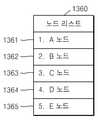
도 13b 는 본원 발명의 일 실시예에 따른 노드 리스트를 나타낸 도면이다.
도 14 는 본원 발명의 일 실시예에 따른 초음파 영상들을 나타낸 도면이다.
도 15a 및 도 15b 는 본원 발명의 일 실시예에 따른 초음파 영상을 나타낸 도면이다.
도 16 은 본원 발명의 일 실시예에 따른 초음파 영상을 나타낸 도면으로서 도 15 에서 이어지는 도면이다.
도 17 은 본원 발명의 일 실시예에 따른 초음파 영상을 나타내 도면이다.
도 18 은 본원 발명의 일 실시예에 따라 좌표계 상에 초음파 데이터를 나타낸 도면이다.BRIEF DESCRIPTION OF THE DRAWINGS The present invention can be easily understood by the following detailed description and combination of the accompanying drawings, in which reference numerals mean structural elements.
1 is a view showing an ultrasound imaging apparatus used in the present invention.
2 is a block diagram illustrating a configuration of a
3 is a diagram illustrating an ultrasound diagnosis apparatus according to an embodiment of the present invention.
4 is a diagram illustrating an ultrasound diagnosis apparatus according to an embodiment of the present invention.
5 is a diagram illustrating an ultrasound diagnosis method according to an embodiment of the present invention.
6 is a view for explaining movement of a viewpoint on an ultrasound image of a conventional ultrasound diagnosis apparatus.
7 is a view illustrating movement of a viewpoint on an ultrasound image according to an embodiment of the present invention.
8 is a diagram illustrating movement of a viewpoint on an ultrasound image according to an embodiment of the present invention.
9 is a view showing an ultrasound image according to an embodiment of the present invention.
10 is a diagram illustrating a process of acquiring a node based on a user input according to an embodiment of the present invention.
11A to 11C are diagrams illustrating a process in which the control unit automatically acquires nodes and trunk lines according to an embodiment of the present invention.
12 is a diagram illustrating a process of editing a node according to an embodiment of the present invention.
13A is a diagram illustrating a process of moving between nodes according to an embodiment of the present invention.
13B is a diagram illustrating a node list according to an embodiment of the present invention.
14 is a diagram illustrating ultrasound images according to an embodiment of the present invention.
15A and 15B are views illustrating ultrasound images according to an embodiment of the present invention.
16 is a view showing an ultrasound image according to an embodiment of the present invention, and is a view continuing from FIG. 15 .
17 is a diagram illustrating an ultrasound image according to an embodiment of the present invention.
18 is a diagram illustrating ultrasound data on a coordinate system according to an embodiment of the present invention.
본 발명에서 사용되는 용어는 본 발명에서의 기능을 고려하면서 가능한 현재 널리 사용되는 일반적인 용어들을 선택하였으나, 이는 당 분야에 종사하는 기술자의 의도 또는 판례, 새로운 기술의 출현 등에 따라 달라질 수 있다. 또한, 특정한 경우는 출원인이 임의로 선정한 용어도 있으며, 이 경우 해당되는 발명의 설명 부분에서 상세히 그 의미를 기재할 것이다. 따라서 본 발명에서 사용되는 용어는 단순한 용어의 명칭이 아닌, 그 용어가 가지는 의미와 본 발명의 전반에 걸친 내용을 토대로 정의되어야 한다.The terms used in the present invention have been selected as currently widely used general terms as possible while considering the functions in the present invention, which may vary depending on the intention or precedent of a person skilled in the art, the emergence of new technology, and the like. In addition, in a specific case, there is a term arbitrarily selected by the applicant, and in this case, the meaning will be described in detail in the description of the corresponding invention. Therefore, the term used in the present invention should be defined based on the meaning of the term and the overall content of the present invention, rather than the name of a simple term.
명세서 전체에서 어떤 부분이 어떤 구성요소를 “포함”한다고 할 때, 이는 특별히 반대되는 기재가 없는 한 다른 구성요소를 제외하는 것이 아니라 다른 구성요소를 더 포함할 수 있음을 의미한다. 또한, 명세서에 기재된 “…부”, “…모듈” 등의 용어는 적어도 하나의 기능이나 동작을 처리하는 단위를 의미하며, 이는 하드웨어 또는 소프트웨어로 구현되거나 하드웨어와 소프트웨어의 결합으로 구현될 수 있다.In the entire specification, when a part “includes” a certain element, it means that other elements may be further included, rather than excluding other elements, unless otherwise stated. In addition, the “… wealth", "… The term “module” means a unit that processes at least one function or operation, which may be implemented as hardware or software, or a combination of hardware and software.
명세서 전체에서 "초음파 영상"이란 초음파를 이용하여 획득된 대상체(object)에 대한 영상을 의미한다. 또한, 대상체는 사람 또는 동물, 또는 사람 또는 동물의 일부를 포함할 수 있다. 예를 들어, 대상체는 간, 심장, 자궁, 뇌, 유방, 복부 등의 장기, 또는 혈관을 포함할 수 있다. 또한, 대상체는 팬텀(phantom)을 포함할 수도 있으며, 팬텀은 생물의 밀도와 실효 원자 번호에 아주 근사한 부피를 갖는 물질을 의미할 수 있다.Throughout the specification, the term “ultrasound image” refers to an image of an object obtained using ultrasound. Also, a subject may include a human or animal, or part of a human or animal. For example, the object may include organs such as the liver, heart, uterus, brain, breast, abdomen, or blood vessels. Also, the object may include a phantom, and the phantom may mean a material having a volume very close to the density and effective atomic number of an organism.
또한, 명세서 전체에서 "사용자"는 의료 전문가로서 의사, 간호사, 임상 병리사, 의료 영상 전문가 등이 될 수 있으며, 의료 장치를 수리하는 기술자가 될 수 있으나, 이에 한정되지는 않는다.In addition, throughout the specification, a "user" may be a medical professional, such as a doctor, a nurse, a clinical pathologist, a medical imaging specialist, or a technician repairing a medical device, but is not limited thereto.
이하에서는 도면을 참조하여 본 발명의 실시 예 들을 상세히 설명한다.Hereinafter, embodiments of the present invention will be described in detail with reference to the drawings.
도 1은 본 발명에서 이용되는 초음파 영상장치를 나타내는 도면이다.1 is a view showing an ultrasound imaging apparatus used in the present invention.
도 1을 참조하면, 본 발명에서 이용되는 초음파진단장치의 전체적인 구성이 도시된다.Referring to FIG. 1, the overall configuration of the ultrasound diagnosis apparatus used in the present invention is shown.
도 1을 참조하면, 초음파진단장치(100)는 프로브(2), 초음파 송수신부(10), 영상 처리부(20), 통신부(30), 메모리(40), 입력 디바이스(50), 및 제어부(60)를 포함할 수 있으며, 상술한 여러 구성들은 버스(70)를 통해 서로 연결될 수 있다.Referring to FIG. 1 , the
초음파진단장치(100)는 카트형뿐만 아니라 휴대형으로도 구현될 수 있다. 휴대형 초음파진단장치의 예로는 팩스 시야어(PACS viewer), 스마트 폰(smart phone), 랩탑 컴퓨터, PDA, 태블릿 PC 등이 있을 수 있으나, 이에 제한되지 않는다.The
프로브(2)는, 초음파 송수신부(10)로부터 인가된 구동 신호(driving signal)에 따라 대상체(1)로 초음파 신호를 송출하고, 대상체(1)로부터 반사된 에코 신호를 수신한다. 프로브(2)는 복수의 트랜스듀서를 포함하며, 복수의 트랜스듀서는 전달되는 전기적 신호에 따라 진동하며 음향 에너지인 초음파를 발생시킨다. 또한, 프로브(2)는 초음파진단장치(100)의 본체와 유선 또는 무선으로 연결될 수 있으며, 초음파진단장치(100)는 구현 형태에 따라 복수 개의 프로브(2)를 구비할 수 있다.The
송신부(11)는 프로브(2)에 구동 신호를 공급하며, 펄스 생성부(17), 송신 지연부(18), 및 펄서(19)를 포함한다. 펄스 생성부(17)는 소정의 펄스 반복 주파수(PRF, Pulse Repetition Frequency)에 따른 송신 초음파를 형성하기 위한 펄스(pulse)를 생성하며, 송신 지연부(18)는 송신 지향성(transmission directionality)을 결정하기 위한 지연 시간(delay time)을 펄스에 적용한다. 지연 시간이 적용된 각각의 펄스는, 프로브(2)에 포함된 복수의 압전 진동자(piezoelectric vibrators)에 각각 대응된다. 펄서(19)는, 지연 시간이 적용된 각각의 펄스에 대응하는 타이밍(timing)으로, 프로브(2)에 구동 신호(또는, 구동 펄스(driving pulse))를 인가한다.The
수신부(12)는 프로브(2)로부터 수신되는 에코 신호를 처리하여 초음파 데이터를 생성하며, 증폭기(13), ADC(아날로그 디지털 컨버터, Analog Digital converter)(14), 수신 지연부(15), 및 합산부(16)를 포함할 수 있다. 증폭기(13)는 에코 신호를 각 채널(channel) 마다 증폭하며, ADC(14)는 증폭된 에코 신호를 아날로그-디지털 변환한다. 수신 지연부(15)는 수신 지향성(reception directionality)을 결정하기 위한 지연 시간을 디지털 변환된 에코 신호에 적용하고, 합산부(16)는 수신 지연부(15)에 의해 처리된 에코 신호를 합산함으로써 초음파 데이터를 생성한다. 한편, 수신부(12)는 그 구현 형태에 따라 증폭기(13)를 포함하지 않을 수도 있다. 즉, 프로브(2)의 감도가 향상되거나 ADC(14)의 처리 비트(bit) 수가 향상되는 경우, 증폭기(13)는 생략될 수도 있다.The
영상 처리부(20)는 초음파 송수신부(10)에서 생성된 초음파 데이터에 대한 주사 변환(scan conversion) 과정을 통해 초음파 영상을 생성하고 디스플레이한다. 한편, 초음파 영상은 A 모드(amplitude mode), B 모드(brightness mode) 및 M 모드(motion mode)에서 대상체를 스캔하여 획득된 그레이 스케일(gray scale)의 영상뿐만 아니라, 도플러 효과(doppler effect)를 이용하여 움직이는 대상체를 표현하는 도플러 영상을 포함할 수도 있다. 도플러 영상은, 혈액의 흐름을 나타내는 혈류 도플러 영상 (또는, 컬러 도플러 영상으로도 불림), 조직의 움직임을 나타내는 티슈 도플러 영상, 및 대상체의 이동 속도를 파형으로 표시하는 스펙트럴 도플러 영상을 포함할 수 있다.The
B 모드 처리부(22)는, 초음파 데이터로부터 B 모드 성분을 추출하여 처리한다. 영상 생성부(24)는, B 모드 처리부(22)에 의해 추출된 B 모드 성분에 기초하여 신호의 강도가 휘도(brightness)로 표현되는 초음파 영상을 생성할 수 있다.The B-
마찬가지로, 도플러 처리부(23)는, 초음파 데이터로부터 도플러 성분을 추출하고, 영상 생성부(24)는 추출된 도플러 성분에 기초하여 대상체의 움직임을 컬러 또는 파형으로 표현하는 도플러 영상을 생성할 수 있다.Similarly, the
일 실시 예에 의한 영상 생성부(24)는, 볼륨 데이터에 대한 볼륨 렌더링 과정을 거쳐 3차원 초음파 영상을 생성할 수 있으며, 압력에 따른 대상체(1)의 변형 정도를 영상화한 탄성 영상을 생성할 수도 있다. 나아가, 영상 생성부(24)는 초음파 영상 상에 여러 가지 부가 정보를 텍스트, 그래픽으로 표현할 수도 있다. 한편, 생성된 초음파 영상은 메모리(40)에 저장될 수 있다.The
디스플레이부(25)는 생성된 초음파 영상을 표시 출력한다. 디스플레이부(25)는, 초음파 영상뿐 아니라 초음파진단장치(100)에서 처리되는 다양한 정보를 GUI(Graphic User Interface)를 통해 화면 상에 표시 출력할 수 있다. 한편, 초음파진단장치(100)는 구현 형태에 따라 둘 이상의 디스플레이부(25)를 포함할 수 있다.The
통신부(30)는, 유선 또는 무선으로 네트워크(3)와 연결되어 외부 디바이스나 서버와 통신한다. 통신부(30)는 의료 영상 정보 시스템(PACS, Picture Archiving and Communication System)을 통해 연결된 병원 서버나 병원 내의 다른 의료 장치와 데이터를 주고 받을 수 있다. 또한, 통신부(30)는 의료용 디지털 영상 및 통신(DICOM, Digital Imaging and Communications in Medicine) 표준에 따라 데이터 통신할 수 있다.The
통신부(30)는 네트워크(3)를 통해 대상체(1)의 초음파 영상, 초음파 데이터, 도플러 데이터 등 대상체의 진단과 관련된 데이터를 송수신할 수 있으며, CT, MRI, X-ray 등 다른 의료 장치에서 촬영한 의료 영상 또한 송수신할 수 있다. 나아가, 통신부(30)는 서버로부터 환자의 진단 이력이나 치료 일정 등에 관한 정보를 수신하여 대상체(1)의 진단에 활용할 수도 있다. 나아가, 통신부(30)는 병원 내의 서버나 의료 장치뿐만 아니라, 의사나 환자의 휴대용 단말과 데이터 통신을 수행할 수도 있다.The
통신부(30)는 유선 또는 무선으로 네트워크(3)와 연결되어 서버(35), 의료 장치(34), 또는 휴대용 단말(36)과 데이터를 주고 받을 수 있다. 통신부(30)는 외부 디바이스와 통신을 가능하게 하는 하나 이상의 구성 요소를 포함할 수 있으며, 예를 들어 근거리 통신 모듈(31), 유선 통신 모듈(32), 및 이동 통신 모듈(33)을 포함할 수 있다.The
근거리 통신 모듈(31)은 소정 거리 이내의 근거리 통신을 위한 모듈을 의미한다. 본 발명의 일 실시 예에 따른 근거리 통신 기술에는 무선 랜(Wireless LAN), 와이파이(Wi-Fi), 블루투스, 지그비(zigbee), WFD(Wi-Fi Direct), UWB(ultra wideband), 적외선 통신(IrDA, infrared Data Association), BLE (Bluetooth Low Energy), NFC(Near Field Communication) 등이 있을 수 있으나, 이에 한정되는 것은 아니다.The short-
유선 통신 모듈(32)은 전기적 신호 또는 광 신호를 이용한 통신을 위한 모듈을 의미하며, 일 실시 예에 의한 유선 통신 기술에는 페어 케이블(pair cable), 동축 케이블, 광섬유 케이블, 이더넷(ethernet) 케이블 등이 포함될 수 있다.The
이동 통신 모듈(33)은, 이동 통신망 상에서 기지국, 외부의 단말, 서버 중 적어도 하나와 무선 신호를 송수신한다. 여기에서, 무선 신호는, 음성 호 신호, 화상 통화 호 신호 또는 문자/멀티미디어 메시지 송수신에 따른 다양한 형태의 데이터를 포함할 수 있다.The
메모리(40)는 초음파진단장치(100)에서 처리되는 여러 가지 정보를 저장한다. 예를 들어, 메모리(40)는 입/출력되는 초음파 데이터, 초음파 영상 등 대상체의 진단에 관련된 의료 데이터를 저장할 수 있고, 초음파진단장치(100) 내에서 수행되는 알고리즘이나 프로그램을 저장할 수도 있다.The
메모리(40)는 플래시 메모리, 하드디스크, EEPROM 등 여러 가지 종류의 저장매체로 구현될 수 있다. 또한, 초음파진단장치(100)는 웹 상에서 메모리(40)의 저장 기능을 수행하는 웹 스토리지(web storage) 또는 클라우드 서버를 운영할 수도 있다.The
입력 디바이스(50)는, 사용자로부터 초음파진단장치(100)를 제어하기 위한 데이터를 입력받는 수단을 의미한다. 입력 디바이스(50)는 키 패드, 마우스, 터치 패널, 터치 스크린, 트랙볼, 조그 스위치 등 하드웨어 구성을 포함할 수 있으나 이에 한정되는 것은 아니며, 심전도 측정 모듈, 호흡 측정 모듈, 음성 인식 센서, 제스쳐 인식 센서, 지문 인식 센서, 홍채 인식 센서, 깊이 센서, 거리 센서 등 다양한 입력 수단을 더 포함할 수 있다.The
제어부(60)는 초음파진단장치(100)의 동작을 전반적으로 제어한다. 즉, 제어부(60)는 도 1에 도시된 프로브(2), 초음파 송수신부(10), 영상 처리부(20), 통신부(30), 메모리(40), 및 입력 디바이스(50) 간의 동작을 제어할 수 있다.The
프로브(2), 초음파 송수신부(10), 영상 처리부(20), 통신부(30), 메모리(40), 입력 디바이스(50) 및 제어부(60) 중 일부 또는 전부는 소프트웨어 모듈에 의해 동작할 수 있으나 이에 제한되지 않으며, 상술한 구성 중 일부가 하드웨어에 의해 동작할 수도 있다. 또한, 초음파 송수신부(10), 영상 처리부(20), 및 통신부(30) 중 적어도 일부는 제어부(60)에 포함될 수 있으나, 이러한 구현 형태에 제한되지는 않는다.Some or all of the
초음파 영상을 이용한 질병의 진단을 위하여, 대상체를 포함하는 초음파 영상 내에 진단 부위를 설정 또는 소정 위치를 표시하기 위한 마커(marker)가 설정될 수 있다.In order to diagnose a disease using an ultrasound image, a marker for setting a diagnosis site or displaying a predetermined position in an ultrasound image including an object may be set.
구체적으로, 마커는 사용자가 질병 진단 또는 환자의 건강 이상 유무를 확인하기 위하여 상세히 관찰할 필요가 있는 부분에 설정될 수 있다. 본원에서는 전술한 마커가 설정된 대상체 부위를 보다 정확하게 진단할 수 있도록, 초음파 영상을 변경하여 출력하는 초음파진단장치 및 그에 따른 초음파 영상의 디스플레이 방법을 개시한다.Specifically, the marker may be set at a part that the user needs to observe in detail in order to diagnose a disease or confirm the presence or absence of an abnormality in the patient's health. Disclosed herein are an ultrasound diagnosis apparatus that changes and outputs an ultrasound image so as to more accurately diagnose a part of an object in which the above-described marker is set, and a method of displaying the ultrasound image according thereto.
도 2 는 본 발명의 일 실시 예와 관련된 무선 프로브(200)의 구성을 도시한 블록도이다.2 is a block diagram illustrating a configuration of a
무선 프로브(200)는, 도 1에서 설명한 바와 같이 복수의 트랜스듀서를 포함하며, 구현 형태에 따라 도 1의 초음파 송수신부(10)의 구성을 일부 또는 전부 포함할 수 있다.The
도 2 에 도시된 실시 예에 의한 무선 프로브(200)는, 송신부(210), 트랜스듀서(220), 및 수신부(230)를 포함하며, 각각의 구성에 대해서는 1에서 설명한 바 있으므로 자세한 설명은 생략한다. 한편, 무선 프로브(200)는 그 구현 형태에 따라 수신 지연부(233)와 합산부(234)를 선택적으로 포함할 수도 있다.The
무선 프로브(200)는, 대상체(1)로 초음파 신호를 송신하고 에코 신호를 수신하며, 초음파 데이터를 생성하여 도 1의 초음파진단장치(100)로 무선 전송할 수 있다.The
사용자가 상술한 바와 같은 초음파진단장치로 혈관 및 소화기와 같은 관형조직의 대상체의 초음파 진단 시에 대상체의 복수의 말단에 차례로 시점을 이동하는 과정이 필요할 수 있다. 여기서 시점(view point)은 초음파 영상을 획득하기 위한 소정의 위치에 대응된다. 현재의 초음파진단 장치는 트랙볼(Trackball)을 이용해서 시점을 이동시킨다. 하지만 사용자가 트랙볼로 시점을 일일이 이동시키는 데에 불편함이 있었다. 또한 사용자가 시점을 이동한 후에 지나온 경로를 알 수 없는 불편함이 있었다.When the user performs ultrasound diagnosis of an object of tubular tissue such as blood vessels and digestive organs with the ultrasound diagnosis apparatus as described above, it may be necessary to sequentially move the viewpoint to a plurality of ends of the object. Here, a viewpoint corresponds to a predetermined position for acquiring an ultrasound image. A current ultrasound diagnosis apparatus moves a viewpoint using a trackball. However, it was inconvenient for the user to move the viewpoint one by one with the trackball. In addition, there was the inconvenience of not being able to know the path the user has passed after moving the viewpoint.
이하에서, 도 3 내지 도 17 을 참조하여, 본원 발명의 일 실시예에 따른 초음파 영상에서 시점 이동을 보다 용이하게 하기 위한 장치, 방법 및 컴퓨터판독 가능한 저장매체를 상세히 설명한다.Hereinafter, an apparatus, a method, and a computer-readable storage medium for facilitating movement of a viewpoint in an ultrasound image according to an embodiment of the present invention will be described in detail with reference to FIGS. 3 to 17 .
초음파진단장치는 프로브(Probe)로부터 신호를 획득하여 초음파 영상을 구성한 후, 이미지 상의 특정 장기, 구조물 등의 길이, 각도, 면적, 부피 등을 측정할 수 있다. 이러한 측정을 통해 신체 내 이상 부위의 정보를 획득하거나, 태아 주수(Gestational age) 등에 관한 정보를 획득하기도 한다. 초음파진단장치는 의료적 진단을 보조하는 중요한 수단이기에 의료 현장에서 수시로 사용되며, 사용의 편이성과 더불어 정확성이 요구된다.The ultrasound diagnosis apparatus may obtain a signal from a probe to construct an ultrasound image, and then measure the length, angle, area, volume, etc. of a specific organ or structure on the image. Through this measurement, information on abnormal parts in the body or information on gestational age, etc. may be acquired. Ultrasonic diagnostic devices are frequently used in medical fields because they are an important means of assisting medical diagnosis, and accuracy as well as ease of use are required.
이와 관련하여, 의료 진단의 효율성을 높이기 위하여 의사 등의 사용자가 초음파 영상 상에서 입력 디바이스를 통하여 시점을 보다 용이하게 이동시킬 수 있는 방법이 사용자에게 제공될 필요가 있다.In this regard, in order to increase the efficiency of medical diagnosis, there is a need to provide a method for a user, such as a doctor, to more easily move a viewpoint through an input device on an ultrasound image.
도 3 은 본 발명의 일 실시예에 따른 초음파진단장치를 나타낸 도면이다.3 is a diagram illustrating an ultrasound diagnosis apparatus according to an embodiment of the present invention.
도 3 을 참조하면, 본원 발명의 일 실시예에 따른 초음파진단장치(300)는, 영상 생성부(310) 및 제어부(320)를 포함한다.Referring to FIG. 3 , an
초음파진단장치(300)는 초음파 영상을 생성 및 처리할 수 있는 모든 전자기기로, 도 1에 도시된 초음파진단장치(100)에 동일 대응될 수 있다. 또한, 초음파진단장치(300)는 도 1에 도시된 초음파진단장치(100)와 네트워크(3)를 통하여 연결 가능한 서버(35), 의료 장치(34) 또는 휴대용 단말(36)이 될 수도 있다. 또한, 도 3 의 영상 생성부(310) 및 제어부(320)는 각각 도 1 의 영상 생성부(24) 및 제어부(60)에 동일 대응되므로, 도 1 에서 중복되는 설명은 생략한다.The
영상 생성부(310)는 대상체를 스캔(scan)하여 획득된 초음파 데이터에 기초하여 제 1 초음파 영상을 획득한다. 또한, 제어부(320)는 상기 초음파 데이터에 기초하여 복수개의 노드들(nodes)을 포함하는 제 1 정보를 획득하고, 제 1 정보에 기초하여 시점을 이동하며 제 2 초음파 영상들을 획득하도록 제어한다.The
초음파 데이터는 초음파 데이터 획득부에 의하여 획득될 수 있다. 또한, 초음파 데이터 획득부는 초음파 신호 등을 이용하여 대상체를 스캔함으로써 초음파 데이터를 획득할 수 있으나, 이에 제한되는 것은 아니다. 일 예로, 초음파 데이터 획득부는 도 1 에서 도시한 초음파 송수신부(10)에 동일 대응될 수 있으며, 프로브(2)에서 전송되는 초음파 에코 신호를 수신하고, 수신된 초음파 에코 신호를 이용하여 자체적으로 초음파 데이터를 획득할 수 있다. 또한 초음파 데이터 획득부는 도 2 의 무선 프로브(200)에 동일 대응될 수 있다. 초음파 데이터 획득부는 무선 프로브(200)에서 전송되는 초음파 에코 신호를 수신하고, 수신된 초음파 에코 신호를 이용하여 자체적으로 초음파 데이터를 획득할 수 있다.The ultrasound data may be acquired by the ultrasound data acquisition unit. Also, the ultrasound data acquisition unit may acquire ultrasound data by scanning an object using an ultrasound signal, but is not limited thereto. As an example, the ultrasound data acquisition unit may correspond to the
다른 예로, 초음파 데이터 획득부는 외부 장치로부터 초음파 데이터를 수신할 수도 있다. 예를 들어 초음파 데이터 획득부는 도 1의 네트워크(3)로부터 초음파 데이터를 수신할 수 있다. 다만, 이에 한정되는 것은 아니고, 초음파진단장치(300)는 다양한 방법으로 초음파 영상 데이터를 획득할 수 있다.As another example, the ultrasound data acquisition unit may receive ultrasound data from an external device. For example, the ultrasound data acquisition unit may receive ultrasound data from the
또한, 제어부(320)는 노드들과 노드들을 연결하는 간선을 획득하고 복수개의 노드 및 간선에 근거하여, 제 1 초음파 영상에 포함되는 구조물을 획득하도록 제어할 수 있다. 또한, 제 1 정보는 간선 및 구조물 중 적어도 하나를 포함할 수 있다. 또한, 초음파진단장치(300)는 노드들의 순서를 시점 이동 순서로 획득할 수 있으며, 노드들의 순서 및 제 1 정보에 기초하여 시점을 이동하면 초음파 영상을 획득하도록 제어할 수 있다.Also, the
노드는 특정 지점에 위치한 마디점이며, 노드와 노드 사이는 간선으로 연결될 수 있다. 노드에는 분기점 노드(Branch), 말단노드(Leaf) 및 경로 노드(Path Node)가 있다. 말단 노드는 1 개의 다른 노드와 간선으로 연결되는 노드이다. 경로 노드는 2 개의 다른 노드와 간선으로 연결되는 노드이다. 또한, 분기점 노드는 3 개 이상의 다른 노드와 간선으로 연결되는 노드이다. 구조물은 노드들과 간선을 포함하는 그래프가 될 수 있다. 그래프는 노드와 노드 간의 관계를 표시하는 간선으로 구성된 그림을 나타낸다. 또한, 구조물은 노드들과 간선에 의해 형성되는 대상체에 대응되는 형태를 가질 수 있다. 예를 들어, 대상체가 혈관을 포함하는 심장인 경우, 구조물은 혈관의 분포를 사용자가 쉽게 파악할 수 있도록 실제 혈관과 동일 또는 유사한 형태를 갖는 혈관 구조물이 될 수 있다. 또한 노드는 대상체의 영상에 포함될 수 있으며, 디스플레이부가 초음파 영상과 함께 표시할 수 있다.A node is a node located at a specific point, and a node may be connected with an edge. A node includes a branch node, a leaf node, and a path node. A terminal node is a node connected to one other node by an trunk line. A path node is a node connected by an edge to two other nodes. Also, a branch node is a node connected to three or more other nodes by trunk lines. A structure can be a graph including nodes and edges. A graph represents a figure made up of nodes and edges that show the relationships between them. Also, the structure may have a shape corresponding to an object formed by nodes and trunk lines. For example, when the object is a heart including blood vessels, the structure may be a blood vessel structure having the same or similar shape as an actual blood vessel so that a user can easily recognize the distribution of blood vessels. Also, the node may be included in the image of the object, and the display unit may display it together with the ultrasound image.
본원 발명의 다른 실시예에 따르면 노드는 초음파 데이터에 기초하여 획득될 수 있다. 예를 들어 초음파진단장치(300)는 중심선 추출 알고리즘을 이용하여 초음파 데이터로부터 노드들 및 간선 중 적어도 하나를 추출할 수 있다. 초음파진단장치(300)는 노드들 및 간선 중 적어도 하나에 기초하여 초음파 영상을 획득할 수 있다. 예를 들어 초음파진단장치(300)는 노드들 및 간선 중 적어도 하나를 시점으로 획득하고, 시점에서 바라본 초음파 영상을 획득할 수 있다.According to another embodiment of the present invention, a node may be obtained based on ultrasound data. For example, the
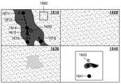
또한 본원 발명의 다른 실시예에 따르면 도 18 (a) 를 참조하면, 초음파 데이터(1820)는 좌표계(1810)상의 데이터일 수 있다. 좌표계(1810)는 직교 좌표계, 원통형 좌표계 및 원좌표계 중 적어도 하나를 포함할 수 있다. 도 18 (a) 에는 좌표계(1810)가 직교 좌표계인 경우를 예시하였다. 제어부(320)는 초음파 데이터(1820)에서 소정의 거리만큼 떨어진 곳에 노드(1830)를 위치 시킬 수 있다. 예를 들어 제어부(320)는 노드를 좌표(x1, y1, z1)에 위치시킬 수 있다. 또한, 초음파진단장치(300)는 노드에 기초하여 초음파 영상을 획득할 수 있다. 예를 들어 초음파진단장치(300)는 노드를 시점으로 획득하고, 초음파 데이터(1820)에 기초하여 시점에서 바라본 초음파 영상을 획득할 수 있다. 이 경우 노드는 초음파 영상에 포함되지 않을 수 있다.Also, according to another embodiment of the present invention, referring to FIG. 18A ,
또한 위에서는 노드를 중심으로 설명하였으나, 이에 한정되는 것은 아니다. 예를 들어, 초음파 데이터(1850)는 좌표계(1840) 상의 데이터 일 수 있다. 초음파진단장치(300)는 초음파 데이터(1850)에서 소정의 거리만큼 떨어진 곳에 궤도(1860)를 위치 시킬 수 있다. 또한, 초음파진단장치(300)는 궤도에 기초하여 초음파 영상을 획득할 수 있다. 예를 들어 초음파진단장치(300)는 초음파 데이터(1850)에 기초하여 궤도에서 바라본 초음파 영상을 획득할 수 있다.In addition, although the above description has been focused on nodes, the present invention is not limited thereto. For example, the
초음파 영상은 제 1 초음파 영상과 제 2 초음파 영상을 포함할 수 있다. 제 1 초음파 영상은 대상체를 초음파 스캔하여 획득된 초음파 데이터에 기초하여 획득되는 영상이다. 구체적으로, 제 1 초음파 영상은 사용자가 관찰할 부분을 결정하기 위하여 이용되는, 대상체의 초음파 영상이다. 제 1 초음파 영상은 2D 단면 초음파 영상 및 3D 렌더링된 내시경 영상 중 적어도 하나가 될 수 있다. 또한 제 2 초음파 영상은 사용자가 대상체의 초음파 영상을 관찰하기 위해 초음파진단장치가 획득하는 초음파 영상이다. 구체적으로, 제 2 초음파 영상은 제 1 초음파 영상에 포함되는 소정 영역에 대응되는 초음파 영상이 될 수 있다. 예를 들어, 제 2 초음파 영상은 제 1 초음파 영상의 소정의 부분을 확대하여 나타낸 초음파 영상일 수 있다.The ultrasound image may include a first ultrasound image and a second ultrasound image. The first ultrasound image is an image obtained based on ultrasound data obtained by performing an ultrasound scan of an object. Specifically, the first ultrasound image is an ultrasound image of the object used to determine a portion to be observed by the user. The first ultrasound image may be at least one of a 2D cross-sectional ultrasound image and a 3D rendered endoscopic image. Also, the second ultrasound image is an ultrasound image obtained by the ultrasound diagnosis apparatus for a user to observe an ultrasound image of an object. Specifically, the second ultrasound image may be an ultrasound image corresponding to a predetermined region included in the first ultrasound image. For example, the second ultrasound image may be an ultrasound image in which a predetermined portion of the first ultrasound image is enlarged.
또 다른 예로, 제 2 초음파 영상은 제 1 초음파 영상의 소정의 부분의 단면을 나타내는 초음파 영상일 수 있다. 사용자는 대상체의 초음파 영상인 제 1 초음파 영상을 관찰하고, 관찰한 제 1 초음파 영상 상에서 앞으로 관찰할 부분을 결정한 후, 이러한 결정에 대응되는 제 2 초음파 영상을 관찰 할 수 있으므로, 실질적으로 제 1 초음파 영상과 제 2 초음파 영상은 하나의 화면 상에 디스플레이될 수 있다. 하지만, 이에 한정되는 것은 아니며, 사용자의 편의를 위해 제 1 초음파 영상과 제 2 초음파 영상은 서로 다른 화면을 통하여 디스플레이 될 수 있다. 예를 들어 제 1 초음파 영상은 제 2 초음파 영상의 소정의 부위에 미니 초음파 영상으로서 표시될 수도 있다. 제 1 초음파 영상은 대상체에 대한 초음파 영상의 전체를 표시한 영상일 수 있다. 제 2 초음파 영상은 제 1 초음파 영상의 소정의 영역을 확대한 화면일 수 있다. 제 1 초음파 영상은 제 2 초음파 영상의 소정의 부분에 표시되어, 사용자는 제 1 초음파 영상에 나타난 전체 그림을 보고 제 2 초음파 영상이 어느 부위의 확대 화면인지 확인할 수 있다.As another example, the second ultrasound image may be an ultrasound image representing a cross-section of a predetermined portion of the first ultrasound image. Since the user observes a first ultrasound image that is an ultrasound image of an object, determines a portion to be observed in the future on the observed first ultrasound image, and observes a second ultrasound image corresponding to the determination, substantially the first ultrasound image The image and the second ultrasound image may be displayed on one screen. However, the present invention is not limited thereto, and for the convenience of the user, the first ultrasound image and the second ultrasound image may be displayed on different screens. For example, the first ultrasound image may be displayed as a mini ultrasound image on a predetermined portion of the second ultrasound image. The first ultrasound image may be an image in which the entire ultrasound image of the object is displayed. The second ultrasound image may be a screen obtained by magnifying a predetermined area of the first ultrasound image. The first ultrasound image is displayed on a predetermined portion of the second ultrasound image, and the user can check the enlarged screen of which part of the second ultrasound image by looking at the entire picture displayed in the first ultrasound image.
또한 제 2 초음파 영상은 제 1 초음파 영상을 영상 처리하여 2D 및 3D 중 적어도 하나로 표현한 영상일 수 있다. 또한 제 2 초음파 영상은 초음파 데이터에 기초한 가상 내시경 영상을 포함할 수 있다. 따라서 사용자는 실제로 내시경을 하지 않고도 초음파진단장치를 이용하여 간편하게 대략적인 피검사자의 내시경 진단을 할 수 있다. 본 개시에서는 제 1 초음파 영상 및 제 2 초음파 영상의 구분이 필요한 곳에서는 구분하여 기재하였으나, 구분이 필요 없는 부분은 제 1 초음파 영상 및 제 2 초음파 영상을 포함하는 초음파 영상으로 기재하였다.Also, the second ultrasound image may be an image in which the first ultrasound image is image-processed and expressed in at least one of 2D and 3D. Also, the second ultrasound image may include a virtual endoscope image based on ultrasound data. Accordingly, the user can easily perform an endoscopic diagnosis of a subject by using the ultrasound diagnosis device without actually having an endoscope. In the present disclosure, the first ultrasound image and the second ultrasound image are separately described where it is necessary, but the part where the distinction is not required is described as an ultrasound image including the first ultrasound image and the second ultrasound image.
제어부(320)는 제 1 초음파 영상에 노드들 및 간선을 획득하고, 초음파 영상 상의 노드들 및 간선에서의 시점을 획득하여 사용자에게 제 2 초음파 영상을 제공할 수 있다. 본 발명에 따르면 시점은 노드들 및 간선을 따라 자동으로 이동될 수 있다. 구체적으로, 제어부(320)는 초음파 영상의 시점을 이동시키는데 있어서 일정 방향 또는 미리 설정된 규칙에 따라서 초음파 영상의 시점이 이동되도록 제어할 수 있다. 따라서, 사용자는 트랙볼로 시점을 이동해야 하는 수고를 덜 수 있다.The
도 4 은 본 발명의 다른 실시예에 따른 초음파진단장치를 나타낸 도면이다.4 is a view showing an ultrasound diagnosis apparatus according to another embodiment of the present invention.
도 4 를 참조하면, 본원 발명의 다른 실시예에 따른 초음파진단장치(400)는, 영상 생성부(310), 제어부(320), 입력부(430) 및 디스플레이부(440)를 포함한다. 초음파진단장치(400)에 포함되는 영상 생성부(410) 및 제어부(420)는 도 3 에서 설명한 영상 생성부(310) 및 제어부(320)와 동일하므로 도 3에서와 중복되는 설명을 생략하고, 이하에서는 입력부(430) 및 디스플레이부(440)에 대하여 설명을 한다.Referring to FIG. 4 , an ultrasound diagnosis apparatus 400 according to another exemplary embodiment of the present invention includes an
입력부(430)는 도 1 의 입력 디바이스(50)에 대응될 수 있으므로 중복되는 설명은 생략한다. 입력부(430)는 사용자로부터 제 1 초음파 영상을 포함하는 사용자 인터페이스 화면을 통하여 사용자 입력을 수신할 수 있다. 입력부(430)는 입력 디바이스(50)에 대응될 수 있다. 예를 들어, 입력부(430)는 터치스크린으로 형성될 수 있으며, 터치스크린 상으로 디스플레이되는 제1 초음파 영상을 포함하는 사용자 인터페이스 화면을 통하여 사용자 입력을 수신할 수 있다. 입력부(430)가 수신한 입력에 기초하여, 제어부(320)는 제 1 초음파 영상에 노드들 및 간선을 획득하고, 초음파 영상 상의 노드들 및 간선에서의 시점을 획득하여 사용자에게 제 2 초음파 영상을 제공할 수 있다. 입력부(430)는 사용자로부터 시점 이동 입력을 수신할 수 있다. 예를 들어, 입력부(430)가 마우스를 포함하는 경우, 사용자는 입력부(430)인 마우스로 노드를 클릭하여 노드와 노드 사이를 시점 이동할 수 있다.Since the
또한, 입력부(430)가 수신한 입력에 기초하여, 제어부(320)는 노드들의 순서를 획득할 수 있다. 제어부(320)는 노드들의 순서에 기초하여 시점을 이동하면서 초음파 영상을 획득할 수 있다.Also, based on the input received by the
디스플레이부(440)는 도 1 의 디스플레이부(25)에 대응될 수 있으므로 도 1에서와 중복되는 설명은 생략한다. 디스플레이부(440)는 제어부(340)의 제어에 따라서 소정 화면을 디스플레이한다. 구체적으로, 디스플레이부(440)는 디스플레이 패널(display panel)(미도시)을 포함하며, 디스플레이 패널 상으로 사용자 인터페이스 화면, 초음파 영상 등을 포함하는 의료 영상 화면 등을 디스플레이 할 수 있다. 디스플레이부(440)는 제 1 초음파 영상 및 제 2 초음파 영상을 디스플레이 할 수 있다. 또한 제어부(320)는 제 1 정보에 근거하여 시점의 위치 및 방향 중 적어도 하나를 나타내는 제 2 정보를 획득할 수 있다. 디스플레이부(440)는 제 1 정보 및 제 2 정보 중 적어도 하나를 제 1 초음파 영상 상에 표시한 영상을 디스플레이할 수 있다. 여기서 시점의 방향(direction of viewpoint; 시선)은 초음파 영상을 획득하기 위한 소정의 위치에서의 방향을 의미한다.Since the
또한, 본 발명의 다른 실시예에 따르면 초음파진단장치(400)는 영상 생성부(410), 제어부(420) 및 입력부(430)를 포함할 수 있다. 영상 생성부(410)는 대상체를 스캔(scan)하여 제 1 초음파 영상을 획득할 수 있다. 또한, 입력부(430)는 사용자로부터 입력을 수신할 수 있다. 또한, 제어부(420)는 제 1 초음파 영상에 포함되는 복수개의 노드들(nodes)을 포함하는 제 1 정보를 획득하고, 제 1 정보 및 수신된 입력에 기초하여 시점을 이동하며 제 2 초음파 영상들을 획득하도록 제어할 수 있다.Also, according to another embodiment of the present invention, the ultrasound diagnosis apparatus 400 may include an
또한, 본 발명의 다른 실시예에 따르면 초음파진단장치(400)는 영상 생성부(410), 제어부(420) 및 디스플레이부(440)를 포함할 수 있다. 영상 생성부(410)는 대상체를 스캔(scan)하여 제 1 초음파 영상을 획득할 수 있다. 제어부(420)는 제 1 초음파 영상에 포함되는 복수개의 노드들 및 간선 중 적어도 하나를 포함하는 제 1 정보를 획득하고, 제 1 정보에 기초하여 시점을 이동하며 제 2 초음파 영상들을 획득하도록 제어할 수 있다. 또한 디스플레이부(440)는 시점이 지나간 제 1 정보를 시점이 지나가지 않은 제 1 정보와 서로 구별되도록 디스플레이할 수 있다. 디스플레이부(440)는 시점이 지나간 제 1 정보와 시점이 지나가지 않은 제 1 정보가 서로 구별되도록, 서로 다른 모양, 색, 투명도, 애니메이션 효과, 텍스트 등을 이용할 수 있다.Also, according to another embodiment of the present invention, the ultrasound diagnosis apparatus 400 may include an
또한, 본 발명의 다른 실시예에 따르면 초음파진단장치(400)는 영상 생성부(410), 제어부(420) 및 입력부(430)를 포함할 수 있다. 영상 생성부(410)는 대상체를 스캔(scan)하여 제 1 초음파 영상을 획득할 수 있다. 입력부(430)는 사용자로부터 입력을 수신할 수 있다. 제어부(420)는 제 1 초음파 영상에 포함되는 복수개의 노드들(nodes)을 포함하는 제 1 정보를 획득하고, 수신된 입력에 기초하여 노드들의 순서를 획득하고, 노드들의 순서에 기초하여 시점을 이동하며 제 2 초음파 영상들을 획득하도록 제어할 수 있다.Also, according to another embodiment of the present invention, the ultrasound diagnosis apparatus 400 may include an
도 5 는 본 발명의 일 실시예에 따른 초음파진단방법을 나타낸 도면이다.5 is a diagram illustrating an ultrasound diagnosis method according to an embodiment of the present invention.
도 5 를 참조하면, 본원 발명의 일 실시예에 따른 초음파진단방법은 제 1 초음파 영상을 획득하는 단계(510), 제 1 정보를 획득하는 단계(520), 제 2 초음파 영상들을 획득하는 단계(540)를 포함할 수 있다. 본 발명의 실시예에 따른 초음파진단방법은 도 3 및 도 4에서 설명한 본 발명의 실시예에 따른 초음파진단장치(300, 400)을 통하여 수행될 수 있다. 이하에서는 초음파진단장치(400)를 참조하여 본 발명의 실시예에 따른 초음파 진단 방법을 설명한다. 또한, 본 발명의 실시예에 따른 초음파 진단 방법의 상세한 설명에 있어서, 도 3 및 도 4를 참조하여 설명한 본 발명의 실시예에 따른 초음파진단장치(300, 400)에서와 중복되는 설명은 생략한다.Referring to FIG. 5 , the ultrasound diagnosis method according to an embodiment of the present invention includes acquiring a first ultrasound image ( 510 ), acquiring first information ( 520 ), and acquiring second ultrasound images ( ). 540) may be included. The ultrasound diagnosis method according to the embodiment of the present invention may be performed through the
제 1 초음파 영상을 획득하는 단계(510)는 대상체를 스캔(scan)하여 초음파 데이터를 획득하고 초음파 데이터에 기초하여 영상 생성부(410)가 제 1 초음파 영상을 획득하는 단계이다. 510 단계의 동작은 프로브(2)를 통하여 전송되는 초음파 데이터에 근거하여 획득되는 제1 초음파 영상을 초음파진단장치(400)가 외부적으로 수신하거나 자체적으로 생성함으로써 수행될 수 있다. 제 1 정보를 획득하는 단계(520)는 제어부(420)가 초음파 데이터에 기초하여 복수개의 노드들(nodes)을 포함하는 제 1 정보를 획득하는 단계이다. 520 단계의 동작은 제어부(420)에서 수행될 수 있다. 또한 제어부(420)는 제 1 정보에 기초하여 시점을 이동하며 제 2 초음파 영상들을 획득하는 단계를 수행할 수 있다.Acquiring the
제어부(420)는 제 1 정보에 근거하여 시점의 위치 및 방향 중 적어도 하나를 나타내는 제 2 정보를 획득하는 단계를 수행할 수 있다. 또한 제어부(420)의 제어에 따라서 디스플레이부(440)는 제 1 정보 및 제 2 정보 중 적어도 하나를 제 1 초음파 영상 상에 표시한 영상을 디스플레이하는 단계를 수행할 수 있다.The
제어부(320)는 노드들과 노드들을 연결하는 간선을 획득하는 단계 및 복수개의 노드 및 간선에 근거하여, 제 1 초음파 영상에 포함되는 구조물을 획득하는 단계를 수행할 수 있다. 제 1 정보는 간선 및 구조물 중 적어도 하나를 포함할 수 있다.The
제 2 초음파 영상들을 획득하는 단계(540)는, 노드들 중 적어도 두 개의 노드들의 순서를 자동으로 획득하는 단계(단계 미도시); 및 영상 생성부가 획득된 노드들의 순서로 시점을 이동하며 제 2 초음파 영상들을 획득하는 단계(단계 미도시)를 포함할 수 있다.The step of acquiring the
입력부(430)는 사용자로부터 제 1 초음파 영상 상에 제 1 정보와 관련한 입력을 수신하는 단계를 수행할 수 있다.The
제어부(320)는 수신된 입력에 기초하여 노드들 및 간선 중 적어도 하나를 추가, 이동 및 삭제 중 적어도 하나를 수행하는 단계를 수행할 수 있다.The
제 2 초음파 영상들을 획득하는 단계(540)는, 사용자로부터 노드들 중 적어도 하나의 노드들을 선택하는 입력을 수신하는 단계, 및 선택된 노드들에 기초하여 제 2 초음파 영상들을 자동으로 획득하는 단계를 포함할 수 있다.The step of acquiring
제 2 초음파 영상들을 획득하는 단계는, 사용자로부터 노드들 중 적어도 하나의 노드들을 선택하는 입력을 수신하는 단계, 및 선택된 노드들을 제외한 노드들에 기초하여 제 2 초음파 영상들을 자동으로 획득하는 단계를 포함할 수 있다.Acquiring the second ultrasound images may include receiving an input for selecting at least one node among nodes from a user, and automatically acquiring second ultrasound images based on nodes excluding the selected nodes. can do.
입력부(430)는 사용자로부터 노드들 중 적어도 두 개의 노드들의 순서에 관련된 입력을 수신하는 단계를 수행할 수 있다. 제어부(320)는 수신된 노드들의 순서에 관련된 입력에 기초하여 시점을 이동하며 제 2 초음파 영상들을 획득하는 단계를 수행할 수 있다.The
입력부(430)는 사용자로부터 노드와 노드 사이의 이동속도에 관련된 입력을 수신하는 단계를 수행할 수 있다. 제어부(320)는 이동속도에 기초하여 시점을 이동하며 제 2 초음파 영상들을 획득하는 단계를 수행할 수 있다. 또한, 상기 이동속도에 관련된 입력은 노드들 사이의 이동 시간을 포함할 수 있다. 따라서 사용자는 노드들 사이의 이동속도를 설정하여 자세히 관찰해야 하는 곳은 천천히 시점을 이동시킬 수 있다.The
제 1 정보를 획득하는 단계는 중심선 추출 알고리즘을 포함하는 영상처리를 이용하여 초음파 영상으로부터 노드들 및 간선을 포함하는 제 1 정보를 추출하는 단계를 포함할 수 있다.Obtaining the first information may include extracting the first information including nodes and trunk lines from the ultrasound image using image processing including a centerline extraction algorithm.
제 2 초음파 영상들을 획득하는 단계는, 추출된 제 1 정보에 기초하여 시점을 이동하며 자동으로 제 2 초음파 영상들을 획득하는 단계를 포함할 수 있다.The acquiring of the second ultrasound images may include moving a viewpoint based on the extracted first information and automatically acquiring the second ultrasound images.
제 2 초음파 영상들을 획득하는 단계는, 노드 및 노드 사이의 간선을 따라 시점을 이동하며 제 2 초음파 영상들을 획득하는 단계를 포함할 수 있다.The acquiring of the second ultrasound images may include acquiring the second ultrasound images while moving a viewpoint along a node and a trunk line between the nodes.
디스플레이부(440)는 시점이 지나간 영상들을 획득한 노드들 및 간선 중 적어도 하나를 디스플레이하는 단계를 수행할 수 있다.The
또한 디스플레이부(440)는 시점이 지나간 노드들 및 간선 중 적어도 하나를 시점이 지나가지 않은 노드들 및 간선과 서로 다른 투명도, 색 및 모양 중 적어도 하나로 디스플레이하는 단계를 수행할 수 있다. 예를 들어, 시점이 지나가지 않은 노드들 및 간선이 시점이 지나간 노드들 및 간선보다 투명하게 표시될 수 있다. 또한 시점이 지나가지 않은 노드들 및 간선이 시점이 지나간 노드들 및 간선과 다른 색으로 표시될 수 있다. 또한, 시점이 지나가지 않은 노드들은 세모로 시점이 지나간 노드들은 동그라미로 표시될 수 있다. 또한, 시점이 지나가지 않은 노드들 및 간선이 시점이 지나간 노드들 및 간선과 다른 애니메이션 효과를 이용하여 표시될 수 있다.Also, the
본 발명의 다른 실시예에 따른 초음파진단방법은 초음파 데이터 획득부(미도시)가 대상체를 스캔(scan)하여 초음파 데이터를 획득하는 단계를 수행할 수 있다. 또한 입력부(430)가 사용자로부터 입력을 수신하는 단계를 수행할 수 있다. 또한, 제어부(420)가 초음파 데이터에 기초하여 복수개의 노드들(nodes)을 포함하는 제 1 정보를 획득하는 단계 및 제 1 정보 및 수신된 입력에 기초하여 시점을 이동하며 초음파 영상을 획득하는 단계를 수행할 수 있다.In the ultrasound diagnosis method according to another embodiment of the present invention, an ultrasound data acquisition unit (not shown) may scan an object to acquire ultrasound data. Also, the
본 발명의 다른 실시예에 따른 초음파진단방법은 초음파 데이터 획득부가 대상체를 스캔(scan)하여 초음파 데이터를 획득하는 단계를 수행할 수 있다. 또한 제어부(420)가 초음파 데이터에 기초하여 복수개의 노드들 및 간선 중 적어도 하나를 포함하는 제 1 정보를 획득하는 단계 및 제 1 정보에 기초하여 시점을 이동하도록 제어하는 단계를 수행할 수 있다. 또한, 디스플레이부(440)는 시점이 지나간 제 1 정보를 시점이 지나가지 않은 제 1 정보와 서로 구별되도록 디스플레이하는 단계를 수행할 수 있다. 디스플레이부(440)는 시점이 지나간 제 1 정보와 시점이 지나가지 않은 제 1 정보가 서로 구별되도록, 서로 다른 모양, 색, 투명도, 애니메이션 효과, 텍스트 등을 이용할 수 있다.In the ultrasound diagnosis method according to another embodiment of the present invention, the ultrasound data acquisition unit may scan an object to acquire ultrasound data. Also, the
본 발명의 다른 실시예에 따른 초음파진단방법은 영상 생성부(410)가 대상체를 스캔(scan)하여 제 1 초음파 영상을 획득하는 단계를 수행할 수 있다. 또한 입력부(430)가 사용자로부터 입력을 수신하는 단계를 수행할 수 있다. 또한 제어부(420)가 수신된 입력에 기초하여 제 1 초음파 영상에 포함되는 복수개의 노드들(nodes)을 포함하는 제 1 정보를 획득하는 단계, 수신된 입력에 기초하여 노드들의 순서를 획득하는 단계를 수행할 수 있다. 또한 제 1 정보 및 노드들의 순서에 기초하여 시점을 이동하며 제 2 초음파 영상들을 획득하는 단계를 수행할 수 있다.In the ultrasound diagnosis method according to another embodiment of the present invention, the
또한, 도 5 에 따른 초음파진단방법을 수행하기 위한 프로그램이 기록된 컴퓨터로 판독 가능한 기록 매체가 있을 수 있다.In addition, there may be a computer-readable recording medium in which a program for performing the ultrasound diagnosis method according to FIG. 5 is recorded.
도 6 은 기존 초음파진단장치의 초음파 영상 상에서 시점 이동을 설명하기 위한 도면이다.6 is a view for explaining movement of a viewpoint on an ultrasound image of a conventional ultrasound diagnosis apparatus.
도 6 을 참조하면, 일반적인 초음파 진단장치는 사용자가 관심영역을 관찰하기 위한 시점 이동에 어려움이 있었다. 일반적인 초음파진단장치의 경우, 트랙볼을 통하여 입력되는 사용자 입력에 대응하여 초음파 영상의 시점을 조절한다. 사용자는 대상체의 진단을 위하여 초음파 영상의 시점을 이동시켜가면서 대상체를 관찰하여야 한다. 이하에서는 사용자가 트랙볼을 통하여 시점을 이동시키는 경우를 예로 들어 설명한다. 예를 들어 사용자가 도 6 의 초음파 영상(650) 상의 지점(653) 및 지점(654)을 차례대로 보기 위한 과정을 살펴보면 이하와 같다. 도 6(a)를 참조하면, 초음파 영상(610) 상에 초기 시점(611)이 지점(612)에 위치해 있다. 초음파 영상(610)상에 시점은 실제로 표시되지 않을 수 있으나 본 개시에서는 설명의 편의상 카메라 모양으로 시점을 표시하였다.Referring to FIG. 6 , in a general ultrasound diagnosis apparatus, it is difficult for a user to move a viewpoint for observing a region of interest. In the case of a general ultrasound diagnosis apparatus, a viewpoint of an ultrasound image is adjusted in response to a user input input through a trackball. In order to diagnose the object, the user must observe the object while moving the viewpoint of the ultrasound image. Hereinafter, a case in which the user moves the viewpoint through the trackball will be described as an example. For example, a process for a user to sequentially view a
도 6(b)를 참조하면, 사용자는 초음파 영상(620)을 보면서 트랙볼을 이용하여 지점(622)로부터 지점(622) 및 지점(623)의 갈림길까지 시점(621)을 이동해야 한다. 다음으로 도 6(c)를 참조하면, 사용자는 초음파 영상(630)을 보면서 트랙볼을 이용하여 지점(633)까지 시점(631)을 이동해야 한다. 계속하여, 도 6(d)를 참조하면, 사용자는 초음파 영상(640) 상의 지점(644)로 이동하기 위하여 시점(641)을 다시 지점(643)과 지점(644)의 분기점까지 이동해야 한다. 다음으로 도 6(e)를 참조하면, 초음파 영상(650) 상의 최종 목적지 지점(654)까지 시점(651)을 이동해야 한다. 이러한 종래 기술은 사용자가 시점을 트랙볼을 이용하여 수동으로 이동해야 하므로, 초음파진단의 시점 이동에 불편함이 있었다.Referring to FIG. 6B , the user needs to move a
또한, 도 6 은 갈림길이 2개인 경우이나 갈림길이 여러 갈래인 경우, 사용자가 이미 관찰한 영역과 관찰하지 않은 영역을 쉽게 파악하기 힘든 문제점이 있었다. 예를 들어, 초음파 영상(640) 상에서 사용자는 지점(643)으로부터 분기점까지 시점(641)을 이동하였다. 지점(642)에 대응되는 영역은 초음파 영상(610) 상에서 이미 관찰한 지점이므로 사용자는 지점(644)에 대응되는 영역을 관찰하길 원할 수 있다. 하지만, 종래 초음파진단장치(300)는 이동 경로 또는 관찰한 지점이 초음파 영상(640) 상에 표시되지 않았으므로, 사용자는 관찰하지 않은 지점이 지점(642)인지 아니면 지점(644)인지 헷갈릴 수 있다. 게다가 초음파 영상(640)이 실시간 영상인 경우, 초음파 영상이 계속적으로 변할 수 있으므로 문제는 더 심각해질 수 있다. 본원 발명은 이러한 종래 기술의 문제점을 해소할 수 있다.In addition, in FIG. 6 , when there are two fork lengths or several fork lengths, there is a problem in that it is difficult for the user to easily identify an already observed area and a non-observed area. For example, on the
본 발명의 실시예에 따른 초음파진단장치의 구체적인 동작은 이하에서 도 7 내지 도 17 을 참조하여 상세히 설명한다. 또한, 이하에서는 본 발명의 일 실시예에 따른 초음파진단장치로, 도 4 에 도시된 초음파진단장치(300)를 예로 들어 설명한다.A detailed operation of the ultrasound diagnosis apparatus according to the embodiment of the present invention will be described in detail below with reference to FIGS. 7 to 17 . In the following, the
도 7 은 본원 발명의 일 실시예에 따른 초음파 영상 상에서 시점 이동을 나타낸 도면이다.7 is a view illustrating movement of a viewpoint on an ultrasound image according to an embodiment of the present invention.
제 1 초음파 영상(710) 또는 초음파 데이터 중 적어도 하나에 기초하여 제어부(320)는 노드들(717, 712, 713 및 714)을 획득할 수 있다. 또한 노드와 노드 사이에 간선들(715, 716 및 718)을 획득할 수 있다. 노드들(717, 712, 713 및 714) 및 간선들(715, 716 및 718)은 트리 구조로 형성될 수 있다. 노드들은 제 1 정보에 포함될 수 있다. 노드들 각각은 디스플레이부(440) 상의 복수의 픽셀들 각각에 대응될 수 있다.Based on at least one of the
제어부(320)는 노드들 중 적어도 두 개의 노드들의 순서를 자동으로 획득하고, 영상 생성부(310)가 획득된 노드들의 순서로 시점을 이동하며 제 2 초음파 영상들을 획득하도록 제어할 수 있다. 예를 들어, 제어부(320)는 노드들(717, 712, 713 및 714) 및 간선들(715, 716 및 718) 중 적어도 하나의 이동 순서를 결정할 수 있다. 모든 노드를 통과하기 위하여 제어부(320)는 노드들의 순서(717 -> 712 -> 713 -> 712 -> 714)를 자동으로 획득할 수 있다. 또한, 제어부(320)는 간선을 따라 화면을 이동하도록 제어하여 제 2 초음파 영상들을 획득하도록 제어할 수 있다. 예를 들어 사용자로부터 소정의 입력을 수신한 초음파진단장치(300)는 초음파 영상(720) 상에서 시점을 이동시키면서 제 2 초음파 영상을 획득할 수 있다. 즉, 제어부(320)는 초음파 영상(720) 상에서 시점(721)을 최초 노드(727)에서 간선(728)을 따라 노드(722)까지 이동하도록 제어할 수 있다. 그 후 제어부(320)는 시점(721)을 획득된 노드들의 순서에 기초하여 간선(725)을 따라 노드(723)까지 이동하도록 제어할 수 있다.The
또한, 제어부(320)는 제 1 정보 및 수신된 사용자의 입력에 기초하여 시점을 이동하며 초음파 영상을 획득하도록 제어할 수 있다. 예를 들어 초음파 영상(710)을 참조하면, 시점이 노드(712)에 위치해 있는 경우 입력부(430)는 사용자로부터 노드(713)으로 시점을 이동하라는 입력을 수신할 수 있다. 더 구체적으로 사용자는 마우스를 이용하여 노드(713)를 클릭할 수 있다. 초음파진단장치(300)는 수신한 입력에 기초하여 시점을 노드(712)에서 노드(713)으로 이동할 수 있다. 또한 초음파진단장치(300)는 시점을 노드(713)으로 이동 후 초음파 영상을 획득할 수 있다.Also, the
디스플레이부(440)는 초음파 영상(720) 상에 시점(721)이 이미 지나간 제 1 정보(예를 들어, 노드들 및 간선들)를 지나가지 않은 제 1 정보(예를 들어, 노드들 및 간선들)와 구별되도록 표시할 수 있다. 즉, 디스플레이부(440)는 시점(721)이 이동하며 초음파 영상을 획득한 노드들 및 간선을, 초음파 영상을 획득하지 못한 노드들 및 간선과 구별되도록 표시할 수 있다. 구체적으로, 디스플레이부(440)는 초음파 영상(720) 상에 시점(721)이 이미 지나간 노드들 및 간선과 지나가지 않은 노드들 및 간선을 다른 모양, 다른 색상, 및 다른 투명도 중 적어도 하나를 이용하여 구별되도록 표시할 수 있다.The
제어부(320)는 시점이 지나가지 않은 노드들 및 간선을 시점이 지나간 노드들 및 간선보다 투명하게 표시하도록 제어할 수 있다. 또한 제어부(320)는 시점이 지나가지 않은 노드들 및 간선을 시점이 지나간 노드들 및 간선과 다른 색으로 표시하도록 제어할 수 있다. 또한, 제어부(320)는 시점이 지나가지 않은 노드들을 세모로 시점이 지나간 노드들을 동그라미로 표시하도록 제어할 수 있다. 또한, 제어부(320)는 시점이 지나가지 않은 노드들 및 간선이 시점이 지나간 노드들 및 간선과 다른 애니메이션 효과를 이용하여 표시하도록 제어할 수 있다.The
또한, 제어부(320)는 노드들과 간선을 리스트로 표시하도록 제어할 수 있다. 제어부(320)는 리스트에서 시점이 지나가지 않은 노드들 및 간선을 시점이 지나간 노드들 및 간선과 구별되도록 표시하도록 제어할 수 있다. 예를 들어 초음파진단장치(300)는 리스트에서 제 2 초음파 영상을 획득한 노드들 및 간선의 글자를 두껍게 표시하거나, 글씨체를 달리할 수 있다. 또한, 초음파진단장치(300)는 리스트에서 제 2 초음파 영상을 획득한 노드들 및 간선의 글자 옆에 소정의 아이콘을 표시할 수 있다.Also, the
예를 들어 시점(721)이 지나간 노드들(727, 722 및 723)은 흰색 원으로 표시될 수 있으며, 지나가지 않은 노드(724)는 검은색 원으로 표시될 수 있다. 또한 시점(721)이 지나간 간선들(728 및 725)는 점선으로 표시될 수 있다. 사용자는 이미 관찰한 노드 및 간선을 용이하게 파악할 수 있다. 도 7 에서는 시점이 지나간 노드들 및 간선들을 초음파 영상(720) 상에 점과 선으로 표시하는 실시예를 도시하였으나 이에 한정되는 것은 아니다. 예를 들어, 시점이 지나간 노드들의 명칭 및 간선의 명칭을 리스트 형식으로 보여줄 수 있다.For example,
다음으로 시점(731)은 노드(733)에서 간선(735)을 지나 노드(732)에 도달할 수 있다. 그 후 시점(731)은 획득된 노드들의 순서에 따라 간선(736)을 따라 노드(734)에 도달할 수 있다. 시점(731)이 모든 노드들 및 간선들을 지나갔으므로, 초음파진단장치(300)는 초음파 영상(730) 상에 시점(731)이 이미 지나간 노드들 및 간선들은 지나가지 않은 노드들 및 간선들과 서로 다른 모양, 다른 색상, 및 다른 투명도 중 적어도 하나를 이용하여 구별되도록 표시할 수 있다. 서로 다른 모양, 다른 색상 및 다은 투명도 중 적어도 하나를 이용하여 구별되도록 표시하는 것은 이미 상술하였으므로 설명은 생략한다. 입력부(430)는 사용자로부터 노드들 중 적어도 두 개의 노드들의 순서에 관련된 입력을 수신하고, 제어부(320)는 수신된 노드들의 순서에 관련된 입력에 기초하여 시점을 이동하며 제 2 초음파 영상들을 획득할 수 있다.Next, the
예를 들어 도 7 을 참조하여 설명하면, 본원 입력부(430)는 사용자로부터 노드(713) 및 노드(714)를 차례로 선택하는 입력을 수신할 수 있다. 예를 들어 사용자는 시점(711)이 노드(717)에 있은 것을 보고, 노드(713) 및 노드(714)를 차례로 클릭할 수 있다. 제어부(320)는 시점(711)의 위치 및 수신된 사용자의 입력에 기초하여 노드들의 순서(717 -> 712 -> 713 -> 712 -> 714)를 자동으로 획득할 수 있다. 노드(712)는 사용자에 의하여 직접적으로 선택된 적은 없지만, 시점(711)이 노드(717)에서 간선들을 따라 노드(713)으로 이동하기 위해서, 노드(712)가 노드들의 순서에 포함될 수 있다. 제어부(320)는 획득된 노드들의 순서대로 시점을 이동하여 초음파 영상을 획득하도록 제어할 수 있다. 시점의 이동 과정은 상술한 바 있으므로 여기에서 따로 설명하지는 않는다.For example, referring to FIG. 7 , the
도 7 에서는 간선을 따라 시점이 이동하는 과정을 설명하였으나 이에 한정되는 것은 아니다. 예를 들어, 본원 입력부(430)는 사용자로부터 노드(713) 및 노드(714)를 차례로 선택하는 입력을 수신할 수 있다. 예를 들어 사용자는 시점(711)이 노드(717)에 있는 것을 보고, 노드(713) 및 노드 (714)를 차례로 클릭할 수 있다. 제어부(320)는 수신된 사용자의 입력에 기초하여 시점이 노드(717)에서 노드(713)로 건너뛰고, 또한 노드(713)에서 노드(714)로 건너뛰도록 제어할 수 있다.Although the process of moving the viewpoint along the trunk line has been described in FIG. 7 , the present invention is not limited thereto. For example, the
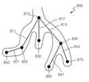
도 8 은 본원 발명의 일 실시예에 따른 초음파 영상 상에서 시점 이동을 나타낸 도면이다.8 is a diagram illustrating movement of a viewpoint on an ultrasound image according to an embodiment of the present invention.
도 8 을 참조하면, 대상체는 혈관이나 소화관, 유관 등과 같은 관형 조직을 포함하는 신체 부위일 수 있다. 영상 생성부(310)는 초음파 데이터에 기초하여 대상체의 제 1 초음파 영상(800)을 획득할 수 있다. 제어부(320)는 초음파 영상(800) 또는 초음파 데이터 중 적어도 하나에 기초하여 노드들(810, 820, 830, 840, 850, 860 및 870) 및 간선들(811, 812, 813, 821, 841 및 842)을 획득할 수 있다. 입력부(430)는 사용자로부터 입력을 수신하고, 제어부(320)는 수신된 입력에 기초하여 노드들 및 간선들을 획득할 수 있다. 또는 제어부(320)가 초음파 영상(800)을 영상처리하여 노드들 및 간선들을 추출할 수 있다. 영상처리는 중심선 추출 알고리즘이 포함될 수 있다. 노드들 중 노드(850), 노드(830), 노드(860) 및 노드(870)는 말단 노드 이다. 또한 노드(820)는 경로 노드이며, 노드(810), 노드(840)는 분기 노드이다.Referring to FIG. 8 , the object may be a body part including a tubular tissue such as a blood vessel, a digestive tract, or a duct. The
도 7 에서 설명한 바와 같이 제어부(320)는 자동으로 모든 노드들 및 간선들을 통과하도록 시점 이동을 수행할 수 있다. 하지만 사용자는 모든 노드들이 아닌 일부 노드들에서 초음파 영상을 획득하고자 하는 경우가 있을 수 있다. 입력부(430)는 사용자로부터 노드들 중 적어도 하나의 노드들을 선택하는 입력을 수신하고 제어부(320)는 선택된 노드들에 기초하여 제 2 초음파 영상들을 자동으로 획득하도록 제어할 수 있다. 또한, 입력부(430)는 사용자로부터 노드들 중 적어도 하나의 노드들을 선택하는 입력을 수신하고 제어부(320)는 선택된 노드들을 제외한 노드들에 기초하여 제 2 초음파 영상들을 자동으로 획득하도록 제어할 수 있다.As described with reference to FIG. 7 , the
본원 발명의 일 실시예에 따른 초음파진단장치는 입력부(430)가 사용자로부터 통과할 노드들을 수신할 수 있다. 예를 들어, 입력부(430)가 사용자로부터 노드(810), 노드(850) 및 노드(860)를 차례로 선택하는 입력을 수신할 수 있다. 이 경우, 제어부(320)는 노드(810), 노드(850) 및 노드(860)를 차례로 통과하도록 시점 이동의 순서를 획득할 수 있다. 또한 초음파진단장치(300)는 시점 이동의 순서를 제 1 정보에 포함할 수 있다.The ultrasound diagnosis apparatus according to an embodiment of the present invention may receive nodes through which the
예를 들어 시점 이동의 순서는 노드(810), 노드(820), 노드(850) 노드(820), 노드(810), 노드(840) 및 노드(860)일 수 있다. 노드(820) 및 노드(840)는 입력부(430)가 사용자로부터 수신한 노드들은 아니지만, 사용자로부터 수신한 노드들을 통과하는 경로 상에 있는 노드로서 제어부(320)가 시점 이동 순서에 추가할 수 있다. 제어부(320)는 상술한 바와 같은 노드들의 순서에 기초하여 간선들을 따라 시점을 이동하며 초음파 영상을 획득하도록 제어할 수 있다. 즉, 제어부(320)는 간선(811), 간선(821), 간선(821), 간선(811), 간선(813) 및 간선(841)을 따라 시점을 이동하며 초음파 영상을 획득하도록 제어할 수 있다. 위에서는 입력부(430)가 사용자로부터 노드들의 선택을 수신하는 예를 설명하였으나 이에 한정되는 것은 아니며 간선을 선택할 수도 있다. 입력부(430)가 사용자로부터 간선들의 선택을 수신하여 제어부(320)가 시점 이동을 하도록 제어하는 것은 상술한 바와 유사하게 이루어 질 수 있다.For example, the order of moving the viewpoint may be a node 810 , a
본원 발명의 다른 실시예에 따른 초음파진단장치는 시점 이동이 간선을 따르지 않을 수도 있다. 예를 들어, 입력부(430)가 사용자로부터 노드(810), 노드(850) 및 노드(860)를 차례로 선택하는 입력을 수신할 수 있다. 이 경우, 제어부(320)는 노드(810), 노드(850) 및 노드(860)를 차례로 통과하도록 시점 이동의 순서를 획득할 수 있다. 예를 들어 시점 이동의 순서는 노드(810), 노드(850) 및 노드(860)일 수 있다. 제어부(320)는 상술한 바와 같은 노드들의 순서에 기초하여 노드(810)에서의 초음파 영상을 획득하고, 다음으로 바로 노드(850)에서의 초음파 영상을 획득하고, 마지막으로 노드(860)에서의 초음파 영상을 차례로 획득하도록 제어할 수 있다. 또한 사용자는 노드들이 아닌 간선을 선택할 수 있으며, 이 경우 제어부(320)는 선택된 간선에서의 초음파 영상을 획득하도록 제어할 수 있다.In the ultrasound diagnosis apparatus according to another embodiment of the present invention, the movement of the viewpoint may not follow the trunk line. For example, the
본원 발명의 다른 실시예에 따른 초음파진단장치는 입력부(430)가 사용자로부터 방문하지 않을 노드들을 수신할 수 있다. 예를 들어, 입력부(430)가 사용자로부터 노드(820), 노드(850) 및 노드(860)를 차례로 선택하는 입력을 수신할 수 있다. 이 경우, 제어부(320)는 노드(820), 노드(850) 및 노드(860)를 제외한 노드(810), 노드(830), 노드(840) 및 노드(870)를 차례로 방문하도록 시점 이동의 순서를 획득할 수 있다. 예를 들어 시점 이동의 순서는 노드(810), 노드(830), 노드(810) 노드(840) 및 노드(870)일 수 있다. 노드(820) 및 노드(840)는 입력부(430)가 사용자로부터 수신한 노드들은 아니지만, 제어부(320)는 상술한 바와 같은 노드들의 순서에 기초하여 간선들을 따라 시점을 이동하며 초음파 영상을 획득하도록 제어할 수 있다. 즉, 제어부(320)는 노드(830), 노드(810), 노드(840) 및 노드(870)로 연결되는 영역을 관찰하기 위해서, 시점을 이동시켜가며 대상체를 관찰하기 위해서, 간선(812)의 위에서 아래 방향 및 간선(812)의 아래 방향에서 윗방향, 간선(813)의 위에서 아래 방향 및 간선(813)의 아래 방향에서 윗방향, 및 간선(842)의 위에서 아래 방향 및 간선(842)의 아래 방향에서 윗방향을 따라 시점을 이동하며 초음파 영상을 획득하도록 제어할 수 있다. 위에서는 입력부(430)가 사용자로부터 방문하지 않을 노드들의 선택을 수신하는 예를 설명하였으나 이에 한정되는 것은 아니며 간선을 선택할 수도 있다. 입력부(430)가 사용자로부터 간선들의 선택을 수신하여 제어부(320)가 시점 이동을 하도록 제어하는 것은 상술한 바와 유사하게 이루어 질 수 있다. 본원 발명의 다른 실시예에 따른 초음파진단장치는 시점 이동이 간선에 기초하지 않을 수도 있다.In the ultrasound diagnosis apparatus according to another embodiment of the present invention, the
도 9 는 본원 발명의 일 실시예에 따른 초음파 영상을 나타낸 도면이다.9 is a view showing an ultrasound image according to an embodiment of the present invention.
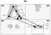
초음파 영상(910)은 대상체의 2차원(2-dimension) 평면도일 수 있다. 또는 초음파 영상(910)은 대상체의 3차원(3D: 3-dimensional) 초음파 영상일 수 있다. 초음파 영상(920)은 대상체의 2차원 측면도 또는 2차원 단면도일 수 있다. 초음파 영상(930)은 대상체의 2D 정면도일 수 있다. 예를 들어, 초음파 영상(940)은 초음파 데이터에 기초하여 정면에서 대상체를 관찰한 3차원 영상일 수 있다. 초음파진단장치(300)는 대상체의 평면도, 측면도, 정면도 및 3차원 초음파 영상 중 적어도 하나를 획득할 수 있다.The
초음파 영상(900)은 사용자가 관찰할 부분을 정하기 위해 획득되는 제 1 초음파 영상 및 사용자가 관찰할 부분의 영상인 제 2 초음파 영상이 함께 표시되어 있을 수 있다. 예를 들어 초음파 영상(910)상에 노드들 및 간선들이 표시되어 있다. 사용자는 초음파 영상(910) 상의 노드들 및 간선들을 선택하여 관찰할 부분을 정할 수 있으므로 초음파 영상(910)은 제 1 초음파 영상이 될 수 있다. 또한 사용자가 초음파 영상(910) 상의 노드들 및 간선들을 선택한 경우 초음파 영상(910)이 해당 노드들 및 간산들을 중심으로 확대될 수 있고, 확대된 초음파 영상(910)이 제 2 초음파 영상이 될 수 있다. 또는 해당 노드들 및 간선에서의 대상체의 3D 초음파 영상(940)이 제 2 초음파 영상이 될 수 있다. 초음파 영상(910)에 대상체의 갈래 구조가 가장 잘 나타나 있어 초음파 영상(910)을 기준으로 설명하였으나 이에 한정되는 것은 아니며, 초음파 영상(920), 초음파 영상(930) 및 초음파 영상(940) 중 적어도 하나에 대해서도 제 1 초음파 영상 및 제 2 초음파 영상이 표시될 수 있다.In the
초음파 영상(910) 상에 노드들(911, 912, 913, 914, 915 및 916)은 입력부(430)가 수신한 사용자로부터의 입력에 의하여 획득될 수 있다. 또한 노드들(911, 912, 913, 914, 915 및 916)은 제어부(320)에 의하여 자동으로 획득될 수 있다. 노드와 노드 사이에는 간선이 있을 수 있다. 노드(912)는 초음파 영상(940) 상의 지점(941)에 대응될 수 있다. 또한, 노드(914)는 초음파 영상(940) 상의 지점(942)에 대응될 수 있다. 도 9 에는 화살표로 대응 관계를 표시하였으나 실제 초음파 영상(900)에는 화살표가 표시되지 않을 수 있다. 또한 노드(915) 및 노드(916)는 초음파 영상(940) 상의 지점(943) 및 지점(944)에 각각 대응될 수 있다.The
도 10 은 본원 발명의 일 실시예에 따른 사용자의 입력에 기초하여 노드를 획득하는 과정을 나타낸 도면이다.10 is a diagram illustrating a process of acquiring a node based on a user input according to an embodiment of the present invention.
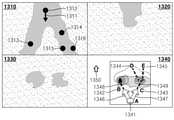
입력부(430)는 사용자로부터 노드들 및 간선 중 적어도 하나를 추가, 이동 및 삭제하는 입력 중 적어도 하나를 수신하고, 제어부(320)는 수신된 입력에 기초하여 노드들 및 간선을 편집할 수 있다.The
예를 들어, 초음파 영상(1010)은 대상체의 평면도 일 수 있다. 입력부(430)는 사용자로부터 입력을 수신하고, 제어부(320)는 수신된 입력에 기초하여 노드를 획득할 수 있다. 예를 들어 사용자는 마우스를 이용하여 초음파 영상(1010) 상에서 노드를 생성하고자 하는 곳에 지시자(1012)를 위치시킬 수 있다. 입력부(430)는 사용자로부터 노드(1011)의 위치에 입력을 수신할 수 있다. 제어부(320)는 수신된 입력에 기초하여 노드(1011)를 획득할 수 있다. 또한 사용자는 초음파 영상(1020) 상에서 지시자(1022)를 이동시킬 수 있다. 입력부(430)는 사용자로부터 노드(1021)의 위치에 입력을 수신할 수 있다. 제어부(320)는 수신된 입력에 기초하여 노드(1021)를 획득할 수 있다. 또한 제어부(320)는 노드(1024) 및 노드(1021)에 기초하여 간선(1023)을 자동으로 획득할 수 있다.For example, the
또한, 상술한 바와 같이, 제어부(320)는 수신된 입력에 기초하여 노드(1021)를 획득하면서, 노드(1024)와 노드(1021)의 시점 이동의 순서를 결정할 수 있다. 예를 들어 기존의 노드(1024)에 더하여 노드(1021)가 추가되었으므로, 제어부(320)는 노드(1024) 및 노드(1021)를 차례로 통과하도록 노드들의 시점 이동 순서를 획득할 수 있다. 제어부(320)는 노드들의 순서 및 제 1 정보에 기초하여 시점을 이동하며 초음파 영상들을 획득하도록 제어할 수 있다.Also, as described above, the
도 11a 내지 도 11c 는 본원 발명의 일 실시예에 따라 제어부가 노드 및 간선을 자동으로 획득하는 과정을 나타낸 도면이다.11A to 11C are diagrams illustrating a process in which the control unit automatically acquires nodes and trunk lines according to an embodiment of the present invention.
제어부(320)는 중심선 추출 알고리즘을 이용하여 초음파 데이터 및 초음파 영상 중 적어도 하나로부터 노드들 및 간선을 추출할 수 있다. 초음파 영상(1100)은 대상체인 혈관의 초음파 영상을 나타낸 도면이다. 혈관은 3D 구조를 가지고 있고 복잡하게 얽혀 있다. 초음파진단장치(300)는 3D 구조의 영상을 영상 처리하여 노드들 및 간선을 획득할 수 있다. 다만 이하에서는 설명의 편의를 위하여 대상체가 2D의 나뭇잎 모양인 경우를 가정하여 노드들 및 간선을 획득하는 과정을 설명하겠다.The
제어부(320)는 초음파 영상(1100)에서 추출된 구조물(예를 들어, 혈관)과 추출되지 않은 구조물이 명확히 구별되도록 영상 처리할 수 있다. 예를 들어, 도 11a 를 참조하면, 초음파 영상(1100)에서 배경(1102)은 흰색으로 대상체(1101)는 검은색으로 표시될 수 있다. 초음파진단장치(300)는 초음파 영상(1100)을 영상 처리하여 대상체(1111)의 중심선을 획득할 수 있다. 예를 들어, 제어부(320)는 대상체(1101)의 검은색에 포함된 각각의 픽셀에 대하여 배경(1102)의 흰색 영역과의 거리를 계산할 수 있다. 예를 들어, 초음파 영상(1100)을 확대한 영상(1105)을 참조하면, 제어부(320)는 대상체(1101)에 포함된 검은색 픽셀(1104)에 대하여 가장 가까운 배경(1102)의 흰색 픽셀(1103)을 결정할 수 있다. 또한, 제어부(320)는 검은색 픽셀(1104)과 결정된 흰색 픽셀(1103)과의 거리를 '2'로 계산할 수 있다. 또한, 제어부(320)는 대상체(1101)에 포함된 검은색 픽셀(1107)에 대하여 가장 가까운 배경(1102)의 흰색 픽셀(1106)을 결정할 수 있다. 또한, 제어부(320)는 검은색 픽셀(1107)과 결정된 흰색 픽셀(1106)과의 거리를 '1'로 계산할 수 있다. 또한 제어부(420)는 계산된 거리를 픽셀값으로 한 영상(1110)을 획득할 수 있다.The
영상(1110)을 참조하면, 계산된 픽셀값이 적용된 대상체(1111)가 표시되어 있다. 즉 대상체(1111)는 중심으로 갈수록 밝은 색이 배경쪽으로 갈수록 어두운 색이 표시될 수 있다.Referring to the
제어부(320)는 영상(1110)에 적절한 커널(kernel)을 적용할 수 있다. 예를 들어 적절한 커널은 반경 2 를 갖는 라플라스-가우시안 커널일 수 있다. 제어부(320)는 영상처리한 영상(1120)을 획득할 수 있다. 영상(1120)은 영상(1110)에 기초하여 중심선(1121)을 획득할 수 있다.The
제어부(320)는 영상(1120)을 영상처리하여 중심선(1131)만을 획득할 수 있다. 영상(1130)은 흰색 바탕에 검은색 중심선(1131)을 포함할 수 있다.The
또한, 도 11b 를 참조하면, 제어부(320)는 영상(1130)을 파티셔닝 할 수 있다. 파티셔닝은 영상(1130)을 조각내어 조각 별로 분석하는 것을 의미한다. 영상(1140)을 참조하면 영상(1130)이 16 X 22 의 조각으로 나누어져 있다. 조각(1141)을 확대한 영상(1150)을 참조하면 4 X 4 픽셀로 이루어져 있음을 알 수 있다. 영상(1150)에는 검은색 픽셀(1151)과 흰색 픽셀(1152)을 포함할 수 있다. 제어부(320)는 조각(1141) 별로 검은색 픽셀의 중심 픽셀을 결정할 수 있다. 예를 들어 영상(1150)에서 검은색 픽셀들의 좌표는 각각 (2, 1),(2, 2), (3, 2), (3, 3) 및 (3, 4) 일 수 있다. 중심 픽셀의 좌표는 아래 <식 1> 에 의하여 계산될 수 있다.Also, referring to FIG. 11B , the
<식 1><
XCM = (Σi∈검은색 픽셀들 Xi)/검은색 픽셀들의 개수XCM = (Σi∈black pixels Xi)/number of black pixels
YCM = (Σi∈검은색 픽셀들 Yi)/검은색 픽셀들의 개수
YCM = (Σi∈black pixels Yi)/number of black pixels
즉, XCM = (2+2+3+3+3)/5=2.6, YCM = (1+2+2+3+4)/5=2.4 일 수 있으며 각각의 값을 반올림하여 (XCM, YCM) = (3, 2) 일 수 있다. 계산된 중심 픽셀들은 노드들이 될 수 있다. 또한 노드 및 노드를 잇는 선은 간산이 될 수 있다.That is, XCM = (2+2+3+3+3)/5=2.6, YCM = (1+2+2+3+4)/5=2.4 can be rounded up to (XCM, YCM) ) = (3, 2). The computed center pixels may be nodes. Also, a node and a line connecting the nodes may be interpolated.
도 11c 를 참조하면, 상술한 바와 같은 과정을 통하여 제어부(320)는 중심 픽셀들 및 중심 픽셀들을 잇는 선으로 이루어진 영상(1160)을 획득할 수 있다. 다만 영상(1160)의 영역(1161)에는 작은 사이클들(cycles)(1170)이 있을 수 있다. 제어부(320)는 이러한 사이클을 제거한 영상(1180)을 획득할 수 있다. 영역(1181)을 참조하면 영역(1161)과 차이가 있음을 알 수 있다. 제어부(320)는 도 11 에서 설명된 과정으로 획득된 노드들 및 간선들에 기초하여 제 2 초음파 영상들을 획득할 수 있다.Referring to FIG. 11C , through the above-described process, the
도 12 는 본원 발명의 일 실시예에 따라 노드를 편집하는 과정을 나타낸 도면이다.12 is a diagram illustrating a process of editing a node according to an embodiment of the present invention.
초음파 영상(1210)에는 노드들을 포함할 수 있다. 사용자는 노드를 삭제하기 위하여 표시자(1213)를 이동하여 노드(1211)를 선택할 수 있다. 입력부(430)는 사용자로부터 입력을 수신할 수 있다. 제어부(320)는 수신된 입력에 기초하여 노드(1211)를 삭제할 수 있다. 초음파 영상(1220)을 참조하면 노드(1211)가 삭제되어 있다. 또한 노드(1211) 및 노드(1212)를 연결하는 간선 또한 삭제될 수 있다. 도 12 에서는 노드를 삭제하는 실시예를 도시하였으나, 이와 유사한 과정에 의하여 노드의 위치의 수정 및 추가가 가능할 수 있다.The ultrasound image 1210 may include nodes. The user may select the
도 13a 는 본원 발명의 일 실시예에 따라 노드 사이를 이동하는 과정을 나타낸 도면이다.13A is a diagram illustrating a process of moving between nodes according to an embodiment of the present invention.
초음파 영상(1310)은 대상체의 2D 평면도일 수 있다. 초음파 영상(1320)은 대상체의 2D 측면도일 수 있다. 초음파 영상(1330)은 대상체의 2D 정면도일 수 있다. 초음파 영상(1340)은 초음파 데이터에 기초한 대상체의 3D 영상일 수 있다. 초음파진단장치(300)는 대상체의 평면도, 측면도, 정면도 및 3차원 초음파 영상 중 적어도 하나를 획득할 수 있다.The
초음파 영상(1300)은 사용자가 관찰할 부분을 정하기 위해 이용되는 제 1 초음파 영상 및 사용자가 대상체의 초음파 영상을 관찰하기 위해 이용되는 관찰할 부분의 영상인 제 2 초음파 영상이 함께 표시되어 있을 수 있다. 예를 들어 초음파 영상(1310)은 사용자가 대상체를 관찰할 수 있도록 초음파 진단장치가 획득하는 초음파 영상이면서, 사용자가 관찰할 부분을 결정하기 위하여 이용되는 초음파 영상일 수 있다.In the ultrasound image 1300 , a first ultrasound image used by the user to determine a portion to be observed and a second ultrasound image that is an image of a portion to be observed used by the user to observe an ultrasound image of an object may be displayed together. . For example, the
구체적으로 초음파 영상(1310) 상에 간선이 없이 노드들이 표시되어 있을 수 있다. 초음파진단장치(300)는 사용자의 입력에 기초하여 간선을 획득하여 표시할 수 있다. 사용자는 초음파 영상(1310) 상의 노드들을 선택하여 관찰할 부분을 정할 수 있으므로 초음파 영상(1310)은 제 1 초음파 영상이 될 수 있다. 또한 사용자가 초음파 영상(1310) 상의 노드들을 선택한 경우 초음파 영상(1310)이 선택된 노드들을 중심으로 확대될 수 있고, 확대된 초음파 영상(1310)이 제 2 초음파 영상이 될 수 있다. 또한, 선택된 노드를 시점으로하여 관찰한 대상체의 3D 초음파 영상(1340)이 제 2 초음파 영상이 될 수 있다. 위에서는 초음파 영상(1310)에 대상체의 갈래 구조가 가장 잘 나타나 있어 초음파 영상(1310)을 기준으로 설명하였으나 이에 한정되는 것은 아니며, 초음파 영상(1320), 초음파 영상(1330) 및 초음파 영상(1340) 중 적어도 하나에 대해서도 제 1 초음파 영상 및 제 2 초음파 영상이 표시될 수 있다.In more detail, nodes may be displayed without trunk lines on the
제어부(320)는 제 1 정보에 근거하여 시점의 위치 및 방향 중 적어도 하나를 나타내는 제 2 정보를 획득할 수 있다. 또한, 디스플레이부(440)는 제 1 정보 및 제 2 정보 중 적어도 하나를 제 1 초음파 영상 상에 표시한 영상을 디스플레이할 수 있다. 여기서 시점의 방향(direction of viewpoint; 시선)은 초음파 영상을 획득하기 위한 소정의 위치에서의 방향을 의미한다. 예를 들어 초음파 영상(1310)에는 제 2 정보인 시점의 위치 및 시선(1311)이 디스플레이될 수 있다. 시점의 위치는 노드(1312)가 될 수 있다. 시점의 위치 및 시선(1311)에 기초하여 대상체의 3D 영상이 초음파 영상(1340)에 디스플레이될 수 있다. 초음파진단장치(300)는 사용자로부터 시선을 수정하는 입력을 수신할 수 있으며, 수정된 시선에 기초하여 초음파 영상들(1310 내지 1340) 중 적어도 하나가 수정될 수 있다.The
현재 시점은 노드(1312)에 위치해 있을 수 있다. 초음파 영상(1340)에는 각 노드에 이름이 할당될 수 있다. 예를 들어 노드(1312), 노드(1313), 노드(1314), 노드(1315) 및 노드(1316)는 각각 A노드(1341), B노드(1342), C노드(1343), D노드(1344) 및 E노드(1345)로 이름이 할당될 수 있다. 또한 이름이 할당된 노드들이 표시된 초음파 영상(1340)이 디스플레이부(440)에 디스플레이될 수 있다.The current view may be located at
또한, 초음파 영상(1340)에는 시점 이동을 위한 아이콘들(1346 및 1347)을 디스플레이 할 수 있다. 초음파진단장치(300)는 사용자의 입력에 기초하여 로 아이콘을 선택하여 시점을 이동할 수 있다. 예를 들어, 사용자는 입력부(430)를 이용하여 표시자(1350)를 움직여서 아이콘(1347)을 선택할 수 있다. 제어부(320)는 사용자로부터 수신한 선택에 기초하여, 간선(1349)을 따라 A노드(1341)에서 C노드(1343)까지 시점을 이동할 수 있다. 또한, 사용자는 입력부(430)를 이용하여 표시자(1350)를 움직여서 아이콘(1346)을 선택할 수 있다. 제어부(320)는 사용자로부터 수신한 선택에 기초하여, 간선(1348)을 따라 A노드(1341)에서 B노드(1342)까지 시점을 이동할 수 있다.Also,
도 13b는 본원 발명의 일 실시예에 따른 노드 리스트를 나타낸 도면이다.13B is a diagram illustrating a node list according to an embodiment of the present invention.
본원 발명의 일 실시예에 따르면, 노드 리스트(1360)가 초음파 영상(1300)과 함께 디스플레이부(440)의 소정의 부위에 표시될 수 있다. 노드 리스트(1360)에는 제어부(320)가 획득한 노드들(1361 내지 1365)이 나타날 수 있다. 또한 사용자는 표시자(1350)로 노드들 중 하나를 선택하여 시점을 이동할 수 있다. 예를 들어, 사용자는 입력부(430)를 이용하여 표시자(1350)를 움직여서 B노드(1362)를 선택할 수 있다. 제어부(320)는 사용자로부터 수신한 선택에 기초하여, A노드(1341)에서 B노드(1342)까지 시점을 이동할 수 있다.According to an embodiment of the present invention, the
또한, 노드 리스트(1360)에서 제 2 초음파 영상을 획득한 노드(즉, 시점이 지나간 노드)는 제 2 초음파 영상을 획득하지 않은 노드(즉, 시점이 지나가지 않은 노드)와 다르게 표시될 수 있다. 노드 리스트(1360)에서 제 2 초음파 영상을 획득한 노드들을 제 2 초음파 영상을 획득하지 않은 노드들과 서로 다른 텍스트 서식으로 표시할 수 있다. 예를 들어 초음파진단장치(300)는 제 2 초음파 영상을 획득한 노드의 글자를 두껍게 표시하거나, 글씨체를 달리할 수 있다. 또한, 제 2 초음파 영상을 획득한 노드들의 글자 옆에 소정의 아이콘을 표시할 수 있다.Also, in the
도 13b 에서는 노드들에 대해서만 예시하였으나, 간선들에 대한 간선 리스트도 표시될 수 있다. 또한 간선 리스트에서 제 2 초음파 영상을 획득한 간선(즉, 시점이 지나간 간선)은 제 2 초음파 영상을 획득하지 않은 간선(즉, 시점이 지나가지 않은 간선)과 다르게 표시될 수 있다.Although only nodes are illustrated in FIG. 13B , an edge list for edges may also be displayed. Also, in the trunk list, an trunk on which the second ultrasound image has been acquired (ie, an trunk through which the viewpoint has passed) may be displayed differently from an edge on which the second ultrasound image has not been acquired (ie, an edge on which the viewpoint has not passed).
도 14 내지 도 17 은 본원 발명의 일 실시예에 따라 노드 사이를 이동하는 과정을 나타낸 도면이다.14 to 17 are diagrams illustrating a process of moving between nodes according to an embodiment of the present invention.
도 14 는 본원 발명의 일 실시예에 따른 초음파 영상들을 나타낸 도면이다.14 is a diagram illustrating ultrasound images according to an embodiment of the present invention.
초음파 영상(1410)은 대상체의 2D 평면도일 수 있다. 초음파 영상(1420)은 대상체의 2D 측면도일 수 있다. 초음파 영상(1430)은 대상체의 2D 정면도일 수 있다. 초음파 영상(1440)은 초음파 데이터에 기초한 대상체의 3D 영상일 수 있다. 초음파진단장치(300)는 대상체의 평면도, 측면도, 정면도 및 3차원 초음파 영상 중 적어도 하나를 획득할 수 있다.The ultrasound image 1410 may be a 2D plan view of the object. The
도 14 를 참조하면, 초음파 영상(1410)은 노드들(1411, 1413, 1414, 1415 및 1416)이 표시될 수 있다. 또한, 노드와 노드 사이를 잇는 간선이 표시될 수 있다. 또한 초음파 영상(1410)에 대응되는 3D 초음파 영상(1440)에는 노드들(1441, 1442, 1443, 1444 및 1445)이 표시될 수 있다. 초음파 영상(1410)은 시선(1412)이 표시될 수 있다. 시선(1412)에 기초하여 대상체의 2D 측면도 초음파 영상(1420), 2D 정면도 초음파 영상(1430) 및 3D 영상(1440)이 표시될 수 있다. 초음파진단장치(300)는 사용자로부터 시선을 수정하는 입력을 수신할 수 있으며, 수정된 시선에 기초하여 초음파 영상들(1410 내지 1440)이 수정될 수 있다.Referring to FIG. 14 , in the ultrasound image 1410 ,
사용자는 초음파 영상(1410) 또는 초음파 영상(1440)에서 노드를 표시자(1450)로 선택하여 해당 노드로 시점을 이동할 수 있다. 또한 도 8 에서 설명한 바와 같이 방문할 여러 노드를 선택하거나, 방문하지 않을 여러 노드를 선택할 수도 있다. 예를 들어 사용자가 입력부(430)를 통하여 표시자(1450)로 노드C(1414 또는 1443)를 선택할 수 있다. 제어부(320)는 시점의 위치 및 사용자의 선택에 기초하여 노드A(1411)로부터 노드C(1414)까지 시점을 이동하면서 제 2 초음파 영상을 획득하도록 초음파진단장치(300)를 제어할 수 있다.The user may select a node as the
도 15 는 본원 발명의 일 실시예에 따른 초음파 영상을 나타낸 도면으로서, 도 14 에서 이어지는 도면이다.15 is a view showing an ultrasound image according to an embodiment of the present invention, and is a view continuing from FIG. 14 .
도 15a 를 참조하면, 도 14 에서 사용자가 노드C를 선택하여 시점이 노드C(1512 또는 1541)로 이동하였음을 알 수 있다. 초음파 영상들(1510, 1520, 1530 및 1540)은 시점이 노드C 에 있는 경우의 초음파 영상들이다. 초음파 영상(1510)은 대상체의 2D 평면도일 수 있다. 초음파 영상(1520)은 대상체의 2D 측면도일 수 있다. 초음파 영상(1530)은 대상체의 2D 정면도일 수 있다. 초음파 영상(1540)은 초음파 데이터에 기초한 대상체의 3D 영상일 수 있다. 초음파 영상(1510)은 도 14의 초음파 영상(1410)의 확대화면일 수 있다. 초음파 영상(1520), 초음파 영상(1530) 및 초음파 영상(1540)은 시선(1511)에 기초하여 획득된 초음파 영상일 수 있다.Referring to FIG. 15A , it can be seen that the user selects node C in FIG. 14 and the viewpoint moves to node C 1512 or 1541 . The
도 15a 를 참조하면, 초음파 영상들의 소정의 부위에는 미니 초음파 영상(1570)이 표시될 수 있다. 예를 들어 초음파 영상(1510)의 소정의 영역(1560)에 미니 초음파 영상(1570)이 표시될 수 있다. 미니 초음파 영상은 사용자가 관찰할 부분을 정하기 위해 이용하는 제 1 초음파 영상일 수 있다.Referring to FIG. 15A , a
미니 초음파 영상(1570)에는 초음파 영상(1510)과 다르게 노드A 내지 노드E 가 모두 표시될 수 있다. 초음파진단장치(300)가 제 2 초음파 영상을 획득한 노드들 및 간선은 제 2 초음파 영상을 획득하지 않은 노드들 및 간선과 다르게 미니 초음파 영상(1570) 상에 표시될 수 있다. 따라서 사용자는 제 2 초음파 영상이 획득된 노드들 및 간선을 용이하게 알 수 있다. 예를 들어 노드A(1571) 및 노드C(1573)는 사용자가 관찰한 노드들이므로 노드의 이름인 A 및 C에 네모난 테두리가 표시될 수 있다. 또는 노드의 이름인 A 및 C 가 볼드체(bold)로 표시될 수 있다. 또한 간선(1572)은 이미 관찰한 간선이므로 다른 간선과 다르게 점선으로 표시될 수 있다. 사용자는 미니 초음파 영상(1570) 상에 노드를 클릭하여 해당 노드로 시점을 이동할 수 있다. 도 8 에서 설명한 바와 같이 방문할 여러 노드를 선택하거나, 방문하지 않을 여러 노드를 선택할 수도 있다.Unlike the
또한, 초음파 영상(1510)은 노드들(1512, 1513, 및 1514)을 포함할 수 있다. 또한, 노드와 노드사이를 잇는 간선이 있을 수 있다. 초음파 영상(1510)에는 시선 아이콘(1511)이 표시될 수 있다. 사용자는 입력부(430)를 통하여 시선 아이콘(1511)을 수정할 수 있다. 또한 초음파 영상(1510)에 대응되는 3D 초음파 영상(1540)에는 노드들(1541, 1542 및 1543)이 있을 수 있다. 초음파 영상(1540)에는 시선 아이콘(미도시)이 표시될 수 있다. 사용자는 입력부(430)를 통하여 시선 아이콘을 수정하여 시선을 수정할 수 있다. 수정된 시선에 기초하여 초음파 영상들(1510 내지 1540)이 수정될 수 있다.Also, the
사용자는 초음파 영상(1510) 또는 초음파 영상(1540)에서 노드들 중 하나를 표시자(1550)로 선택하여 해당 노드로 시점을 이동할 수 있다. 또한 도 8 에서 설명한 바와 같이 방문할 여러 노드를 선택하거나, 방문하지 않을 여러 노드를 선택할 수도 있다. 예를들어 사용자가 입력부(430)를 통하여 표시자(1550)로 노드D(1513 또는 1542)를 선택할 수 있다. 제어부(320)는 사용자의 선택에 기초하여 노드C(1512)로부터 노드D(1513)까지 시점을 이동하면서 초음파 영상을 획득하도록 초음파진단장치를 제어할 수 있다. The user may select one of the nodes in the
또한, 도 15b 를 참조하면 디스플레이부(440)는 3차원 초음파 영상(1580)을 단독으로 디스플레이할 수 있다. 3차원 초음파 영상(1580)에는 노드A(1581), 노드C(1582), 노드D(1583) 및 노드E(1584)가 표시될 수 있다. 디스플레이부(440)는 현재 시점이 위치한 노드를 표시하기 위하여 노드C(1582)를 다른 노드들(1581, 1583, 1584)과 다른 도형, 기호, 영상, 텍스트 중 적어도 하나로 디스플레이할 수 있다. 예를 들어 노드C(1582)에 원형 테두리를 표시할 수 있다. 또한 노드C(1582)를 굵은 글씨로 표시할 수 있다.Also, referring to FIG. 15B , the
초음파진단장치(300)는 입력부(430)를 이용하여 사용자로부터 입력을 수신할 수 있다. 또한 초음파진단장치(300)는 사용자로부터 노드들(1581, 1583, 1584) 중 적어도 하나를 선택하는 입력을 수신할 수 있다. 초음파진단장치(300)는 사용자의 선택에 기초하여 시점을 이동하면서 초음파 영상을 획득할 수 있다. 예를 들어 사용자는 마우스를 사용하여 표시자(1550)를 이동할 수 있다. 또한 사용자는 표시자(1550)를 이동하여 노드D(1583)를 선택할 수 있다. 초음파진단장치(300)는 노드C(1582)로부터 노드D(1583)로 시점을 이동하면서 초음파 영상을 획득할 수 있다. 획득된 초음파 영상은 2차원 또는 3차원 초음파 영상일 수 있다. 사용자는 큰 화면에서 3차원 초음파 영상(1580)을 관찰할 수 있고, 피검사자의 내시경 진단을 할 수 있다.도 16 은 본원 발명의 일 실시예에 따른 초음파 영상을 나타낸 도면으로서 도 15 에서 이어지는 도면이다.The
도 16 을 참조하면, 시점(1614)은 노드C(1611)에서 노드D(1615)로 가는 간선 상의 한 지점에 있다. 초음파진단장치는 노드에서 뿐 아니라 간선 상에서의 초음파 영상들(1610, 1620, 1630 및 1640)을 획득할 수 있다. 간선 상에서 시선(1613)은 노드D(1615)를 향할 수 있으나 이에 한정되는 것은 아니다. 초음파 영상(1610)에는 노드들(1611, 1615 및 1616)이 표시될 수 있다. 초음파 영상(1610)에는 시점(1614)이 표시될 수 있다. 또한, 초음파 영상(1640)에는 시점(1641) 및 시선 아이콘(미도시)이 표시될 수 있다. 초음파 영상(1640) 의 시점(16410)은 초음파 영상(1610)의 시점(1614)에 대응될 수 있다. 또한 초음파 영상(1640)에는 노드D(1643)가 디스플레이될 수 있다. 도 14 및 도 15 에서 설명한 바와 같이 사용자는 입력부(430)를 통하여 표시자(1550)로 초음파 영상상의 노드를 선택할 수 있고, 제어부(320)는 사용자의 선택에 기초하여 해당 노드로 시점을 이동할 수 있다.Referring to FIG. 16 , the
또한, 초음파 영상들의 소정의 부위에는 미니 초음파 영상(1660)이 표시될 수 있다. 예를 들어 초음파 영상(1610)의 소정의 영역에 미니 초음파 영상(1660)이 표시될 수 있다. 미니 초음파 영상(1660)은 사용자가 관찰할 부분을 정하기 위해 이용하는 제 1 초음파 영상일 수 있다.Also, a
입력부(430)는 사용자로부터 노드와 노드 사이의 이동속도에 관련된 입력을 수신하고, 제어부(320)는 이동속도에 기초하여 화면을 이동하며 초음파 영상들을 획득하도록 제어할 수 있다. 또한, 상기 이동속도에 관련된 입력은 노드들 사이의 이동 시간을 포함할 수 있다.The
즉, 사용자는 노드와 노드 사이에서의 시점의 이동 속도를 선택할 수 있다. 예를 들어 제어부(320)는 사용자가 선택한 속도에 따라서 노드C(1611)에서 노드D(1615)로 이동할 수 있다. 따라서, 사용자는 노드C(1611)와 노드D(1615) 사이에서도 초음파 영상들(1610, 1620, 1630 및 1640)을 보다 용이하게 관찰할 수 있다. 예를 들어, 사용자는 노드들 사이의 이동속도를 설정하여 자세히 관찰해야 하는 곳은 천천히 시점을 이동시킬 수 있다.That is, the user can select the movement speed of the node and the viewpoint between the nodes. For example, the
도 17 은 본원 발명의 일 실시예에 따른 초음파 영상을 나타내 도면이다.17 is a diagram illustrating an ultrasound image according to an embodiment of the present invention.
초음파 영상(1710)은 시점 이동 경로를 포함하고 있다. 도 14 내지 도 16에서 설명한 바와 같이 시점은 노드A(1711), 간선(1761), 노드C(1713), 간선(1762) 및 노드D(1714)를 순서대로 지나왔다. 제어부(320)는 시점이 지나면서 제 2 초음파 영상을 획득한 노드들을 제 2 초음파 영상을 획득하지 않은 노드들과 다르게 디스플레이 하도록 제어할 수 있다. 또한 제어부(320)는 시점이 지나면서 제 2 초음파 영상을 획득한 간선을 제 2 초음파 영상을 획득하지 않은 간선과 다르게 디스플레이하도록 제어할 수 있다. 예를 들어 노드A(1711), 노드C(1713) 및 노드D(1714)는 시선(1717 및 1718)과 함께 디스플레이될 수 있다. 또한, 간선(1761) 및 간선(1762)은 점선으로 디스플레이될 수 있다. 따라서 사용자는 이미 관찰한 지점을 용이하게 확인할 수 있다. 도 17 에서는 초음파 영상(1710)은 디스플레이부의 소정에 영역에 미니 초음파 영상으로 항상 표시될 수 있고, 사용자는 관찰한 지점을 용이하게 확인할 수 있다. 미니 초음파 영상은 도 15a에서 설명하였으므로 자세한 설명은 생략한다..The ultrasound image 1710 includes a viewpoint movement path. 14 to 16 , the viewpoint passed through the node A 1711 , the trunk 1761 , the node C 1713 , the
초음파 영상(1740)을 참조하면 노드A(1741), 노드C(1743) 및 노드D(1744)는 이미 관찰한 지점이므로 다른 노드들과 다르게 표시될 수 있다. 예를 들어 노드A(1741), 노드C(1743) 및 노드D(1744)는 굵은 글자로 표시될 수 있으나 이에 한정되는 것은 아니다. 시점은 다시 노드A(1741)에 도착하였고 노드A(1741), 노드C(1743) 및 노드D(1744)는 이미 관찰한 지점임을 사용자가 쉽게 알 수 있다.Referring to the
본 개시의 일 실시예에 따른 초음파진단장치(300)는, 초음파 데이터 획득부, 입력부(430), 제어부(320)를 포함할 수 있다. 초음파 데이터 획득부는 대상체를 스캔하여 초음파 데이터를 획득할 수 있다. 또한, 입력부(430)는 사용자로부터 입력을 수신할 수 있다. 또한 제어부(320)는 초음파 데이터에 기초하여 복수개의 노드들을 포함하는 제 1 정보를 획득하고, 제 1 정보 및 수신된 입력에 기초하여 시점을 이동하며 초음파 영상을 획득하도록 제어할 수 있다. 예를 들어 사용자는 마우스 또는 키보드를 포함하는 입력부(430)를 이용하여 노드를 선택할 수 있다. 제어부(320)는 사용자가 선택한 노드에서 바라본 초음파 영상을 초음파 데이터에 기초하여 획득하도록 제어할 수 있다.The
본 개시의 일 실시예에 따른 초음파진단장치(300)는, 초음파 데이터 획득부, 제어부(320) 및 디스플레이부(440)를 포함할 수 있다. 초음파 데이터 획득부는 대상체를 스캔하여 초음파 데이터를 획득할 수 있다. 또한, 제어부는 초음파 데이터에 기초하여 복수개의 노드들 및 간선 중 적어도 하나를 포함하는 제 1 정보를 획득할 수 있다. 또한 제어부(320)는 제 1 정보에 기초하여 시점을 이동하도록 제어할 수 있다. 또한 디스플레이부(440)는 시점이 지나간 제 1 정보를 시점이 지나가지 않은 제 1 정보와 서로 구별되도록 디스플레이할 수 있다. 예를 들어 상술한 바와 같이 제어부(320)는 사용자의 선택에 기초하여 시점을 이동할 수 있다. 디스플레이부(440)는 시점이 지나간 제 1 정보를 시점이 지나가지 않은 제 1 정보와 서로 구별되도록 디스플레이할 수 있다. 즉, 시점이 지나간 제 1 정보를 시점이 지나가지 않은 제 1 정보와 서로 다른 투명도, 색 및 모양 중 적어도 하나로 디스플레이할 수 있다.The
본 개시의 일 실시예에 따른 초음파진단장치(300)는, 영상 생성부(310), 입력부(430) 및 제어부(320)를 포함할 수 있다. 영상 생성부(310)는 대상체를 스캔하여 제 1 초음파 영상을 획득할 수 있다. 입력부(430)는 사용자로부터 입력을 수신할 수 있다. 또한 제어부(320)는 수신된 입력에 기초하여, 제 1 초음파 영상에 포함되는 복수개의 노드들을 포함하는 제 1 정보를 획득할 수 있다. 또한 제어부(320)는 수신된 입력에 기초하여 노드들의 순서를 획득할 수 있다. 또한, 제어부(320)는 노드들의 순서 및 제 1 정보에 기초하여 시점을 이동하며 제 2 초음파 영상들을 획득하도록 제어할 수 있다. 예를 들어, 초음파진단장치(300)는 제 1 초음파 영상에서 사용자 입력에 기초하여 제 1 정보 및 시점 이동 순서를 동시에 획득할 수 있다. 또한 초음파진단장치(300)는 시점이동 순서에 기초하여 시점을 순차적으로 이동하면서 제 2 초음파 영상들을 획득할 수 있다.The
본 개시에 따른 초음파진단장치는 사용자가 시점을 보다 용이하게 이동할 수 있는 인터페이스를 제공할 수 있다.The ultrasound diagnosis apparatus according to the present disclosure may provide an interface through which a user can more easily move a viewpoint.
본원 발명의 실시 예 들과 관련된 기술 분야에서 통상의 지식을 가진 자는 기재의 본질적인 특성에서 벗어나지 않는 범위에서 변형된 형태로 구현될 수 있음을 이해할 수 있을 것이다. 그러므로, 개시된 방법들은 한정적인 관점이 아닌 설명적 관점에서 고려되어야 한다. 본 발명의 범위는 발명의 상세한 설명이 아닌 특허청구 범위에 나타나며, 그와 동등한 범위 내에 있는 모든 차이점은 본 발명의 범위에 포함되는 것으로 해석되어야 한다.Those of ordinary skill in the art related to the embodiments of the present invention will understand that it can be implemented in a modified form within a range that does not deviate from the essential characteristics of the description. Therefore, the disclosed methods are to be considered in an illustrative rather than a restrictive sense. The scope of the present invention is indicated in the claims rather than the detailed description of the invention, and all differences within the scope of equivalents thereto should be construed as being included in the scope of the present invention.
Claims (42)
Translated fromKorean상기 초음파 데이터에 기초하여 복수개의 노드들(nodes)을 포함하는 제 1 정보를 획득하고, 상기 제 1 정보에 기초하여 시점을 이동하며 제 2 초음파 영상들을 획득하도록 제어하는 제어부를 포함하고,
상기 제어부는,
상기 노드들 중 적어도 두 개의 노드들의 순서를 자동으로 획득하고, 상기 영상 생성부가 상기 획득된 노드들의 순서로 자동으로 시점을 이동하며 디스플레이하도록 제어하고,
시점이 지나간 노드들 및 시점이 지나가지 않은 노드들을 서로 다른 투명도, 색 및 모양 중 적어도 하나로, 시점을 지나면서 디스플레이하도록 제어하는 초음파진단장치.an image generator configured to acquire a first ultrasound image based on ultrasound data obtained by scanning an object; and
a control unit configured to obtain first information including a plurality of nodes based on the ultrasound data, move a viewpoint based on the first information, and obtain second ultrasound images,
The control unit is
automatically obtains an order of at least two nodes among the nodes, and controls the image generator to automatically move and display a viewpoint in the order of the obtained nodes,
An ultrasound diagnostic apparatus that controls to display nodes passed by a viewpoint and nodes not passed by a viewpoint, with at least one of different transparency, color, and shape, as the viewpoint passes.
상기 제어부는,
상기 제 1 정보에 근거하여 상기 시점의 위치 및 방향 중 적어도 하나를 나타내는 제 2 정보를 획득하고,
상기 제 1 정보 및 제 2 정보 중 적어도 하나를 상기 제 1 초음파 영상 상에 표시한 영상을 디스플레이하는 디스플레이부를 더 포함하는 초음파진단장치.The method of claim 1,
The control unit is
obtaining second information indicating at least one of a position and a direction of the viewpoint based on the first information;
and a display unit configured to display an image in which at least one of the first information and the second information is displayed on the first ultrasound image.
상기 제어부는,
상기 노드들과 노드들을 연결하는 간선을 획득하고,
상기 복수개의 노드 및 간선에 근거하여, 상기 제 1 초음파 영상에 포함되는 구조물을 획득하도록 제어하고,
상기 제 1 정보는 상기 간선 및 상기 구조물 중 적어도 하나를 포함하는 초음파진단장치.The method of claim 1,
The control unit is
obtaining an edge connecting the nodes and nodes,
controlling to acquire a structure included in the first ultrasound image based on the plurality of nodes and trunk lines;
The first information includes at least one of the trunk line and the structure.
사용자로부터 상기 제 1 초음파 영상 상에 제 1 정보와 관련한 입력을 수신하는 입력부를 더 포함하는 초음파진단장치.The method of claim 1,
The ultrasound diagnosis apparatus further comprising an input unit configured to receive an input related to first information on the first ultrasound image from a user.
상기 제어부는 상기 수신된 입력에 기초하여 상기 노드들 및 간선 중 적어도 하나를 추가, 이동 및 삭제 중 적어도 하나를 하는 초음파진단장치.6. The method of claim 5,
The control unit performs at least one of adding, moving, and deleting at least one of the nodes and the trunk line based on the received input.
상기 입력부는,
사용자로부터 상기 노드들 중 적어도 하나의 노드를 선택하는 입력을 수신하고,
상기 제어부는,
상기 선택된 노드들에 기초하여 제 2 초음파 영상들을 자동으로 획득하도록 제어하는 초음파진단장치.6. The method of claim 5
The input unit,
receiving an input for selecting at least one node among the nodes from a user;
The control unit is
An ultrasound diagnosis apparatus for controlling to automatically acquire second ultrasound images based on the selected nodes.
상기 입력부는,
사용자로부터 상기 노드들 중 적어도 하나의 노드를 선택하는 입력을 수신하고,
상기 제어부는,
상기 선택된 노드들을 제외한 노드들에 기초하여 제 2 초음파 영상들을 자동으로 획득하도록 제어하는 초음파진단장치.6. The method of claim 5
The input unit,
receiving an input for selecting at least one node among the nodes from a user;
The control unit is
An ultrasound diagnosis apparatus for controlling to automatically acquire second ultrasound images based on nodes other than the selected nodes.
상기 입력부는, 사용자로부터 상기 노드들 중 적어도 두 개의 노드들의 순서에 관련된 입력을 수신하고,
상기 제어부는,
상기 수신된 노드들의 순서에 관련된 입력에 기초하여 시점을 이동하며 제 2 초음파 영상들을 획득하도록 제어하는 초음파진단장치.6. The method of claim 5,
The input unit receives an input related to the order of at least two of the nodes from the user,
The control unit is
An ultrasound diagnosis apparatus for controlling to acquire second ultrasound images while moving a viewpoint based on the received input related to the order of the nodes.
상기 입력부는 사용자로부터 노드와 노드 사이의 이동속도에 관련된 입력을 수신하고,
상기 제어부는 상기 이동속도에 기초하여 시점을 이동하며 상기 제 2 초음파 영상들을 획득하도록 제어하는 초음파진단장치.6. The method of claim 5,
The input unit receives an input related to the movement speed between the node and the node from the user,
The control unit moves a viewpoint based on the moving speed and controls to acquire the second ultrasound images.
상기 이동속도에 관련된 입력은 노드와 노드 사이의 이동 시간을 포함하는 초음파진단장치.11. The method of claim 10,
The input related to the movement speed includes a node and a movement time between the nodes.
상기 제어부는,
중심선 추출 알고리즘을 포함하는 영상처리를 이용하여 상기 초음파 영상으로부터 상기 노드들 및 간선을 포함하는 제 1 정보를 추출하는 초음파진단장치.The method of claim 1,
The control unit is
An ultrasound diagnosis apparatus for extracting first information including the nodes and trunk lines from the ultrasound image using image processing including a centerline extraction algorithm.
상기 제어부는,
상기 추출된 제 1 정보에 기초하여 시점을 이동하며 자동으로 상기 제 2 초음파 영상들을 획득하는 초음파진단장치.13. The method of claim 12,
The control unit is
An ultrasound diagnosis apparatus for automatically acquiring the second ultrasound images while moving a viewpoint based on the extracted first information.
상기 제어부는,
상기 노드 및 노드 사이의 간선을 따라 시점을 이동하며 제 2 초음파 영상들을 획득하도록 제어하는 초음파진단장치.The method of claim 1,
The control unit is
An ultrasound diagnosis apparatus for controlling to acquire second ultrasound images while moving a viewpoint along the node and a trunk line between the nodes.
상기 제어부는,
상기 시점이 지나간 노드들 및 간선 중 적어도 하나를 디스플레이하도록 제어하는 초음파진단장치.The method of claim 1,
The control unit is
An ultrasound diagnosis apparatus for controlling to display at least one of nodes and trunk lines passed by the viewpoint.
상기 제어부는,
상기 시점이 지나간 간선을 상기 시점이 지나가지 않은 간선과 서로 다른 투명도, 색 및 모양 중 적어도 하나로 디스플레이하도록 제어하는 초음파진단장치.16. The method of claim 15,
The control unit is
An ultrasound diagnostic apparatus for controlling the trunk line passed by the viewpoint to be displayed in at least one of a transparency, a color, and a shape different from that of the trunk line not passed by the viewpoint.
상기 제 2 초음파 영상들은 초음파 데이터에 기초한 가상내시경 영상을 포함하는 초음파진단장치.The method of claim 1,
The second ultrasound images include a virtual endoscope image based on ultrasound data.
상기 제 2 초음파 영상들은 2 차원 영상 및 3 차원 영상 중 적어도 하나를 포함하는 초음파진단장치.The method of claim 1,
The second ultrasound images include at least one of a 2D image and a 3D image.
상기 구조물은 트리구조의 그래프인 초음파진단장치.4. The method of claim 3,
wherein the structure is a graph of a tree structure.
사용자로부터 입력을 수신하는 입력부; 및
상기 초음파 데이터에 기초하여 복수개의 노드들(nodes)을 포함하는 제 1 정보를 획득하고, 상기 제 1 정보 및 상기 수신된 입력에 기초하여 시점을 이동하며 초음파 영상을 획득하도록 제어하는 제어부를 포함하고,
상기 제어부는,
상기 노드들 중 적어도 두 개의 노드들의 순서를 자동으로 획득하고, 상기 획득된 노드들의 순서로 자동으로 시점을 이동하며 디스플레이하도록 제어하고,
시점이 지나간 노드들 및 시점이 지나가지 않은 노드들을 서로 다른 투명도, 색 및 모양 중 적어도 하나로, 시점을 지나면서 디스플레이하도록 제어하는 초음파진단장치.an ultrasound data acquisition unit configured to acquire ultrasound data by scanning an object;
an input unit for receiving an input from a user; and
A control unit configured to obtain first information including a plurality of nodes based on the ultrasound data, and to move a viewpoint based on the first information and the received input to obtain an ultrasound image, ,
The control unit is
control to automatically obtain the order of at least two nodes among the nodes, automatically move the viewpoint in the order of the obtained nodes, and display;
An ultrasound diagnostic apparatus that controls to display nodes passed by a viewpoint and nodes not passed by a viewpoint, with at least one of different transparency, color, and shape, as the viewpoint passes.
상기 초음파 데이터에 기초하여 복수개의 노드들 및 간선 중 적어도 하나를 포함하는 제 1 정보를 획득하고, 상기 제 1 정보에 기초하여 시점을 이동하도록 제어하는 제어부; 및
상기 시점이 지나간 제 1 정보를 상기 시점이 지나가지 않은 제 1 정보와 서로 구별되도록 디스플레이하는 디스플레이부를 포함하고,
상기 제어부는,
상기 노드들 중 적어도 두 개의 노드들의 순서를 자동으로 획득하고, 상기 디스플레이부가 상기 획득된 노드들의 순서로 자동으로 시점을 이동하며 디스플레이하도록 제어하고,
시점이 지나간 노드들 및 시점이 지나가지 않은 노드들을 서로 다른 투명도, 색 및 모양 중 적어도 하나로, 시점을 지나면서 디스플레이하도록 제어하는 초음파진단장치.an ultrasound data acquisition unit configured to acquire ultrasound data by scanning an object;
a controller for obtaining first information including at least one of a plurality of nodes and trunk lines based on the ultrasound data, and controlling a viewpoint to move based on the first information; and
and a display unit for displaying the first information passed by the viewpoint to be distinguished from the first information not passed by the viewpoint,
The control unit is
automatically obtains the order of at least two nodes among the nodes, and controls the display unit to automatically move and display the view in the order of the obtained nodes,
An ultrasound diagnostic apparatus that controls to display nodes passed by a viewpoint and nodes not passed by a viewpoint, with at least one of different transparency, color, and shape, as the viewpoint passes.
사용자로부터 입력을 수신하는 입력부; 및
상기 수신된 입력에 기초하여, 상기 제 1 초음파 영상에 포함되는 복수개의 노드들(nodes)을 포함하는 제 1 정보를 획득하고, 상기 수신된 입력에 기초하여 상기 노드들의 순서를 획득하고, 상기 노드들의 순서 및 상기 제 1 정보에 기초하여 시점을 이동하며 제 2 초음파 영상들을 획득하도록 제어하는 제어부를 포함하고,
상기 제어부는,
상기 노드들 중 적어도 두 개의 노드들의 순서를 자동으로 획득하고, 상기 영상 생성부가 상기 획득된 노드들의 순서로 자동으로 시점을 이동하며 디스플레이하도록 제어하고,
시점이 지나간 노드들 및 시점이 지나가지 않은 노드들을 서로 다른 투명도, 색 및 모양 중 적어도 하나로, 시점을 지나면서 디스플레이하도록 제어하는 초음파진단장치.an image generator configured to scan an object to acquire a first ultrasound image;
an input unit for receiving an input from a user; and
obtaining first information including a plurality of nodes included in the first ultrasound image based on the received input, obtaining an order of the nodes based on the received input, and obtaining the node a control unit for controlling to acquire second ultrasound images while moving a viewpoint based on the order of the two and the first information;
The control unit is
automatically obtains an order of at least two nodes among the nodes, and controls the image generator to automatically move and display a viewpoint in the order of the obtained nodes,
An ultrasound diagnostic apparatus that controls to display nodes passed by a viewpoint and nodes not passed by a viewpoint, with at least one of different transparency, color, and shape, as the viewpoint passes.
상기 초음파 데이터에 기초하여 복수개의 노드들(nodes)을 포함하는 제 1 정보를 획득하는 단계; 및
제 1 정보에 기초하여 시점을 이동하며 제 2 초음파 영상들을 획득하는 단계를 포함하고,
상기 제 2 초음파 영상들을 획득하는 단계는,
상기 노드들 중 적어도 두 개의 노드들의 순서를 자동으로 획득하는 단계; 및
상기 획득된 노드들의 순서로 자동으로 시점을 이동하며 디스플레이하는 단계를 포함하고,
상기 디스플레이하는 단계는,
시점이 지나간 노드들 및 시점이 지나가지 않은 노드들을 서로 다른 투명도, 색 및 모양 중 적어도 하나로 디스플레이하는 단계를 포함하는 초음파진단방법.acquiring a first ultrasound image based on ultrasound data obtained by scanning an object;
obtaining first information including a plurality of nodes based on the ultrasound data; and
moving a viewpoint based on the first information and acquiring second ultrasound images;
The acquiring of the second ultrasound images includes:
automatically obtaining an order of at least two of the nodes; and
Including the step of automatically moving and displaying the viewpoint in the order of the obtained nodes,
The displaying step is
An ultrasound diagnosis method comprising the step of displaying nodes passed by a viewpoint and nodes not passed by a viewpoint with at least one of different transparency, color, and shape.
상기 제 1 정보에 근거하여 상기 시점의 위치 및 방향 중 적어도 하나를 나타내는 제 2 정보를 획득하는 단계; 및
상기 제 1 정보 및 제 2 정보 중 적어도 하나를 상기 제 1 초음파 영상 상에 표시한 영상을 디스플레이하는 단계를 더 포함하는 초음파진단방법.24. The method of claim 23,
obtaining second information indicating at least one of a position and a direction of the viewpoint based on the first information; and
and displaying an image in which at least one of the first information and the second information is displayed on the first ultrasound image.
상기 노드들과 노드들을 연결하는 간선을 획득하는 단계; 및
상기 복수개의 노드 및 간선에 근거하여, 상기 제 1 초음파 영상에 포함되는 구조물을 획득하는 단계를 더 포함하고
상기 제 1 정보는 상기 간선 및 상기 구조물 중 적어도 하나를 포함하는 초음파진단방법.24. The method of claim 23,
obtaining a trunk line connecting the nodes to the nodes; and
The method further comprising: acquiring a structure included in the first ultrasound image based on the plurality of nodes and trunk lines;
The first information includes at least one of the trunk line and the structure.
사용자로부터 상기 제 1 초음파 영상 상에 제 1 정보와 관련한 입력을 수신하는 단계를 더 포함하는 초음파진단방법.24. The method of claim 23,
The ultrasound diagnosis method further comprising receiving an input related to first information on the first ultrasound image from a user.
상기 수신된 입력에 기초하여 상기 노드들 및 간선 중 적어도 하나를 추가, 이동 및 삭제 중 적어도 하나를 수행하는 단계를 더 포함하는 초음파진단방법.28. The method of claim 27,
and performing at least one of adding, moving, and deleting at least one of the nodes and the trunk line based on the received input.
상기 제 2 초음파 영상들을 획득하는 단계는,
사용자로부터 상기 노드들 중 적어도 하나의 노드를 선택하는 입력을 수신하는 단계; 및
상기 선택된 노드들에 기초하여 제 2 초음파 영상들을 자동으로 획득하는 단계를 포함하는 초음파진단방법.28. The method of claim 27
The acquiring of the second ultrasound images includes:
receiving an input for selecting at least one of the nodes from a user; and
and automatically acquiring second ultrasound images based on the selected nodes.
상기 제 2 초음파 영상들을 획득하는 단계는,
사용자로부터 상기 노드들 중 적어도 하나의 노드를 선택하는 입력을 수신하는 단계; 및
상기 선택된 노드들을 제외한 노드들에 기초하여 제 2 초음파 영상들을 자동으로 획득하는 단계를 포함하는 초음파진단방법.28. The method of claim 27
The acquiring of the second ultrasound images includes:
receiving an input for selecting at least one of the nodes from a user; and
and automatically acquiring second ultrasound images based on nodes other than the selected nodes.
사용자로부터 상기 노드들 중 적어도 두 개의 노드들의 순서에 관련된 입력을 수신하는 단계; 및
상기 노드들의 순서에 관련된 입력에 기초하여 시점을 이동하며 제 2 초음파 영상들을 획득하는 단계를 더 포함하는 초음파진단방법.28. The method of claim 27,
receiving an input related to an order of at least two of the nodes from a user; and
and acquiring second ultrasound images while moving a viewpoint based on an input related to the order of the nodes.
사용자로부터 노드와 노드 사이의 이동속도에 관련된 입력을 수신하는 단계; 및
상기 이동속도에 기초하여 시점을 이동하며 상기 제 2 초음파 영상들을 획득하는 단계를 더 포함하는 초음파진단방법.28. The method of claim 27,
receiving an input related to a node and a movement speed between the nodes from a user; and
The ultrasound diagnosis method further comprising moving a viewpoint based on the moving speed and acquiring the second ultrasound images.
상기 이동속도에 관련된 입력은 노드와 노드 사이의 이동 시간을 포함하는 초음파진단방법.33. The method of claim 32,
The input related to the movement speed includes a node and a movement time between the nodes.
상기 제 1 정보를 획득하는 단계는,
중심선 추출 알고리즘을 포함하는 영상처리를 이용하여 상기 초음파 영상으로부터 상기 노드들 및 간선을 포함하는 제 1 정보를 추출하는 단계를 포함하는 초음파진단방법.24. The method of claim 23,
The step of obtaining the first information comprises:
and extracting first information including the nodes and the trunk line from the ultrasound image using image processing including a centerline extraction algorithm.
상기 제 2 초음파 영상들을 획득하는 단계는,
상기 추출된 제 1 정보에 기초하여 시점을 이동하며 자동으로 상기 제 2 초음파 영상들을 획득하는 단계를 포함하는 초음파진단방법.35. The method of claim 34,
The acquiring of the second ultrasound images includes:
and automatically acquiring the second ultrasound images while moving a viewpoint based on the extracted first information.
상기 제 2 초음파 영상들을 획득하는 단계는,
상기 노드 및 노드 사이의 간선을 따라 시점을 이동하며 제 2 초음파 영상들을 획득하는 단계를 포함하는 초음파진단방법.24. The method of claim 23,
The acquiring of the second ultrasound images includes:
and acquiring second ultrasound images by moving a viewpoint along the node and a trunk line between the nodes.
상기 시점이 지나간 노드들 및 간선 중 적어도 하나를 디스플레이하는 단계를 더 포함하는 초음파진단방법.24. The method of claim 23,
The ultrasound diagnosis method further comprising the step of displaying at least one of nodes and trunk lines passed by the time point.
상기 디스플레이하는 단계는,
상기 시점이 지나간 간선을 상기 시점이 지나가지 않은 간선과 서로 다른 투명도, 색 및 모양 중 적어도 하나로 디스플레이하는 단계를 포함하는 초음파진단방법.38. The method of claim 37,
The displaying step is
and displaying the trunk line passed by the viewpoint in at least one of a transparency, color, and shape different from that of the trunk line not passed by the viewpoint.
사용자로부터 입력을 수신하는 단계;
상기 초음파 데이터에 기초하여 복수개의 노드들(nodes)을 포함하는 제 1 정보를 획득하는 단계; 및
상기 제 1 정보 및 상기 수신된 입력에 기초하여 시점을 이동하며 초음파 영상을 획득하는 단계를 포함하고,
상기 초음파 영상을 획득하는 단계는,
상기 노드들 중 적어도 두 개의 노드들의 순서를 자동으로 획득하는 단계; 및
상기 획득된 노드들의 순서로 자동으로 시점을 이동하며 디스플레이하는 단계를 포함하고,
상기 디스플레이하는 단계는,
시점이 지나간 노드들 및 시점이 지나가지 않은 노드들을 서로 다른 투명도, 색 및 모양 중 적어도 하나로 디스플레이하는 단계를 포함하는 초음파진단방법.acquiring ultrasound data by scanning an object;
receiving input from a user;
obtaining first information including a plurality of nodes based on the ultrasound data; and
moving a viewpoint based on the first information and the received input and acquiring an ultrasound image,
Acquiring the ultrasound image includes:
automatically obtaining an order of at least two of the nodes; and
Including the step of automatically moving and displaying the viewpoint in the order of the obtained nodes,
The displaying step is
An ultrasound diagnosis method comprising the step of displaying nodes passed by a viewpoint and nodes not passed by a viewpoint with at least one of different transparency, color, and shape.
상기 초음파 데이터에 기초하여 복수개의 노드들 및 간선 중 적어도 하나를 포함하는 제 1 정보를 획득하는 단계;
상기 제 1 정보에 기초하여 시점을 이동하도록 제어하는 단계; 및
상기 시점이 지나간 제 1 정보를 상기 시점이 지나가지 않은 제 1 정보와 서로 구별되도록 디스플레이하는 단계를 포함하고,
상기 디스플레이하는 단계는,
상기 노드들 중 적어도 두 개의 노드들의 순서를 자동으로 획득하고, 상기 획득된 노드들의 순서로 자동으로 시점을 이동하며 디스플레이하는 단계; 및
시점이 지나간 노드들 및 시점이 지나가지 않은 노드들을 서로 다른 투명도, 색 및 모양 중 적어도 하나로 디스플레이하는 단계를 포함하는 초음파진단방법.acquiring ultrasound data by scanning an object;
obtaining first information including at least one of a plurality of nodes and a trunk line based on the ultrasound data;
controlling the viewpoint to move based on the first information; and
Displaying the first information passed by the time point to be differentiated from the first information not passed by the time point;
The displaying step is
automatically obtaining an order of at least two nodes among the nodes, and automatically moving and displaying a viewpoint in the order of the obtained nodes; and
An ultrasound diagnosis method comprising the step of displaying nodes passed by a viewpoint and nodes not passed by a viewpoint with at least one of different transparency, color, and shape.
사용자로부터 입력을 수신하는 단계;
상기 수신된 입력에 기초하여, 상기 제 1 초음파 영상에 포함되는 복수개의 노드들(nodes)을 포함하는 제 1 정보를 획득하는 단계;
상기 수신된 입력에 기초하여 상기 노드들의 순서를 획득하는 단계; 및
상기 노드들의 순서 및 상기 제 1 정보에 기초하여 시점을 이동하며 제 2 초음파 영상들을 획득하는 단계를 포함하고,
상기 제 2 초음파 영상들을 획득하는 단계는,
상기 노드들 중 적어도 두 개의 노드들의 순서를 자동으로 획득하는 단계; 및
상기 획득된 노드들의 순서로 자동으로 시점을 이동하며 디스플레이하는 단계를 포함하고,
상기 디스플레이하는 단계는,
시점이 지나간 노드들 및 시점이 지나가지 않은 노드들을 서로 다른 투명도, 색 및 모양 중 적어도 하나로 디스플레이하는 단계를 포함하는 초음파진단방법.acquiring a first ultrasound image by scanning an object;
receiving input from a user;
obtaining first information including a plurality of nodes included in the first ultrasound image based on the received input;
obtaining an order of the nodes based on the received input; and
moving a viewpoint based on the order of the nodes and the first information and acquiring second ultrasound images,
The acquiring of the second ultrasound images includes:
automatically obtaining an order of at least two of the nodes; and
Including the step of automatically moving and displaying the viewpoint in the order of the obtained nodes,
The displaying step is
An ultrasound diagnosis method comprising the step of displaying nodes passed by a viewpoint and nodes not passed by a viewpoint with at least one of different transparency, color, and shape.
Priority Applications (3)
| Application Number | Priority Date | Filing Date | Title |
|---|---|---|---|
| KR1020140180493AKR102364490B1 (en) | 2014-12-15 | 2014-12-15 | Untrasound dianognosis apparatus, method and computer-readable storage medium |
| US14/933,082US10456112B2 (en) | 2014-12-15 | 2015-11-05 | Ultrasound diagnosis apparatus, ultrasound diagnosis method and computer-readable storage medium |
| EP15198247.7AEP3034007B1 (en) | 2014-12-15 | 2015-12-07 | Ultrasound diagnosis apparatus, ultrasound diagnosis method and computer-readable storage medium |
Applications Claiming Priority (1)
| Application Number | Priority Date | Filing Date | Title |
|---|---|---|---|
| KR1020140180493AKR102364490B1 (en) | 2014-12-15 | 2014-12-15 | Untrasound dianognosis apparatus, method and computer-readable storage medium |
Publications (2)
| Publication Number | Publication Date |
|---|---|
| KR20160072614A KR20160072614A (en) | 2016-06-23 |
| KR102364490B1true KR102364490B1 (en) | 2022-02-18 |
Family
ID=54783520
Family Applications (1)
| Application Number | Title | Priority Date | Filing Date |
|---|---|---|---|
| KR1020140180493AActiveKR102364490B1 (en) | 2014-12-15 | 2014-12-15 | Untrasound dianognosis apparatus, method and computer-readable storage medium |
Country Status (3)
| Country | Link |
|---|---|
| US (1) | US10456112B2 (en) |
| EP (1) | EP3034007B1 (en) |
| KR (1) | KR102364490B1 (en) |
Families Citing this family (1)
| Publication number | Priority date | Publication date | Assignee | Title |
|---|---|---|---|---|
| US10912536B2 (en) | 2016-08-23 | 2021-02-09 | Carestream Health, Inc. | Ultrasound system and method |
Citations (4)
| Publication number | Priority date | Publication date | Assignee | Title |
|---|---|---|---|---|
| US20050245803A1 (en) | 2002-03-14 | 2005-11-03 | Glenn Jr William V | System and method for analyzing and displaying computed tomography data |
| JP2011098195A (en)* | 2009-10-08 | 2011-05-19 | Fujifilm Corp | Structure detection apparatus and method, and program |
| JP2014003991A (en) | 2012-06-21 | 2014-01-16 | Toshiba Corp | Ultrasonic diagnostic apparatus and image forming program |
| WO2014024995A1 (en) | 2012-08-08 | 2014-02-13 | 株式会社東芝 | Medical image diagnosis device, image processing device and image processing method |
Family Cites Families (8)
| Publication number | Priority date | Publication date | Assignee | Title |
|---|---|---|---|---|
| US7194117B2 (en)* | 1999-06-29 | 2007-03-20 | The Research Foundation Of State University Of New York | System and method for performing a three-dimensional virtual examination of objects, such as internal organs |
| US6369812B1 (en)* | 1997-11-26 | 2002-04-09 | Philips Medical Systems, (Cleveland), Inc. | Inter-active viewing system for generating virtual endoscopy studies of medical diagnostic data with a continuous sequence of spherical panoramic views and viewing the studies over networks |
| JP4381344B2 (en)* | 2005-05-17 | 2009-12-09 | ジーイー・メディカル・システムズ・グローバル・テクノロジー・カンパニー・エルエルシー | Ultrasonic diagnostic equipment |
| US8821376B2 (en) | 2007-03-12 | 2014-09-02 | David Tolkowsky | Devices and methods for performing medical procedures in tree-like luminal structures |
| US10362962B2 (en) | 2008-11-18 | 2019-07-30 | Synx-Rx, Ltd. | Accounting for skipped imaging locations during movement of an endoluminal imaging probe |
| KR101198608B1 (en) | 2009-09-10 | 2012-11-07 | 주식회사 인피니트헬스케어 | Virtual Endoscopy Apparatus, Method for Driving thereof and Medical Examination Apparatus |
| EP2389113A4 (en) | 2009-09-10 | 2014-04-30 | Infinitt Healthcare Co Ltd | Virtual endoscopy apparatus, method for driving thereof and medical examination apparatus |
| US9295449B2 (en) | 2012-01-23 | 2016-03-29 | Ultrasonix Medical Corporation | Landmarks for ultrasound imaging |
- 2014
- 2014-12-15KRKR1020140180493Apatent/KR102364490B1/enactiveActive
- 2015
- 2015-11-05USUS14/933,082patent/US10456112B2/enactiveActive
- 2015-12-07EPEP15198247.7Apatent/EP3034007B1/enactiveActive
Patent Citations (4)
| Publication number | Priority date | Publication date | Assignee | Title |
|---|---|---|---|---|
| US20050245803A1 (en) | 2002-03-14 | 2005-11-03 | Glenn Jr William V | System and method for analyzing and displaying computed tomography data |
| JP2011098195A (en)* | 2009-10-08 | 2011-05-19 | Fujifilm Corp | Structure detection apparatus and method, and program |
| JP2014003991A (en) | 2012-06-21 | 2014-01-16 | Toshiba Corp | Ultrasonic diagnostic apparatus and image forming program |
| WO2014024995A1 (en) | 2012-08-08 | 2014-02-13 | 株式会社東芝 | Medical image diagnosis device, image processing device and image processing method |
Also Published As
| Publication number | Publication date |
|---|---|
| EP3034007A1 (en) | 2016-06-22 |
| US20160166238A1 (en) | 2016-06-16 |
| EP3034007B1 (en) | 2021-02-03 |
| US10456112B2 (en) | 2019-10-29 |
| KR20160072614A (en) | 2016-06-23 |
Similar Documents
| Publication | Publication Date | Title |
|---|---|---|
| KR102452998B1 (en) | Ultrasonic Diagnostic Apparatus | |
| KR102388132B1 (en) | Method, apparatus and system for generating a body marker which indicates an object | |
| KR102366316B1 (en) | Ultrasonic imaging apparatus and ultrasonic image processing method thereof | |
| KR102310976B1 (en) | Untrasound dianognosis apparatus, method and computer-readable storage medium | |
| US10278674B2 (en) | Ultrasound apparatus and method of displaying ultrasound images | |
| KR102297346B1 (en) | Medical image apparatus and displaying medical image thereof | |
| KR102273831B1 (en) | The Method and Apparatus for Displaying Medical Image | |
| CN106551707B (en) | Apparatus and method for displaying ultrasound image | |
| KR102297148B1 (en) | Ultrasound System And Method For Displaying 3 Dimensional Image | |
| EP3015071A1 (en) | Ultrasound apparatus and information input method thereof | |
| KR102367446B1 (en) | Ultrasonic diagnostic apparatus and operating method for the same | |
| KR20160022100A (en) | Ultrasound diagnosis apparatus and ultrasound diagnosis method | |
| KR101868019B1 (en) | Ultrasound Imaging Apparatus and Method for processing a ultrasound image thereof | |
| EP3040031B1 (en) | Ultrasound diagnosis apparatus and method of operating the same | |
| KR102351127B1 (en) | Ultrasound Diagnostic Method and Ultrasound Diagnostic Apparatus | |
| EP3037041B1 (en) | Method and apparatus for generating body marker | |
| KR102416511B1 (en) | Method and apparatus for generating a body marker | |
| KR102364490B1 (en) | Untrasound dianognosis apparatus, method and computer-readable storage medium | |
| KR102270718B1 (en) | Untrasound dianognosis apparatus, operating method thereof and computer-readable storage medium | |
| KR102270721B1 (en) | Method and apparatus for generating ultrasonic image |
Legal Events
| Date | Code | Title | Description |
|---|---|---|---|
| PA0109 | Patent application | Patent event code:PA01091R01D Comment text:Patent Application Patent event date:20141215 | |
| PG1501 | Laying open of application | ||
| PA0201 | Request for examination | Patent event code:PA02012R01D Patent event date:20191121 Comment text:Request for Examination of Application Patent event code:PA02011R01I Patent event date:20141215 Comment text:Patent Application | |
| E902 | Notification of reason for refusal | ||
| PE0902 | Notice of grounds for rejection | Comment text:Notification of reason for refusal Patent event date:20210517 Patent event code:PE09021S01D | |
| E701 | Decision to grant or registration of patent right | ||
| PE0701 | Decision of registration | Patent event code:PE07011S01D Comment text:Decision to Grant Registration Patent event date:20211115 | |
| GRNT | Written decision to grant | ||
| PR0701 | Registration of establishment | Comment text:Registration of Establishment Patent event date:20220214 Patent event code:PR07011E01D | |
| PR1002 | Payment of registration fee | Payment date:20220215 End annual number:3 Start annual number:1 | |
| PG1601 | Publication of registration |