KR102362654B1 - Oven - Google Patents
OvenDownload PDFInfo
- Publication number
- KR102362654B1 KR102362654B1KR1020150094975AKR20150094975AKR102362654B1KR 102362654 B1KR102362654 B1KR 102362654B1KR 1020150094975 AKR1020150094975 AKR 1020150094975AKR 20150094975 AKR20150094975 AKR 20150094975AKR 102362654 B1KR102362654 B1KR 102362654B1
- Authority
- KR
- South Korea
- Prior art keywords
- door
- oven
- cooking chamber
- monitoring unit
- cable
- Prior art date
- Legal status (The legal status is an assumption and is not a legal conclusion. Google has not performed a legal analysis and makes no representation as to the accuracy of the status listed.)
- Active
Links
Images


Classifications
- F—MECHANICAL ENGINEERING; LIGHTING; HEATING; WEAPONS; BLASTING
- F24—HEATING; RANGES; VENTILATING
- F24C—DOMESTIC STOVES OR RANGES ; DETAILS OF DOMESTIC STOVES OR RANGES, OF GENERAL APPLICATION
- F24C7/00—Stoves or ranges heated by electric energy
- F24C7/08—Arrangement or mounting of control or safety devices
- F24C7/082—Arrangement or mounting of control or safety devices on ranges, e.g. control panels, illumination
- F24C7/085—Arrangement or mounting of control or safety devices on ranges, e.g. control panels, illumination on baking ovens
- H—ELECTRICITY
- H04—ELECTRIC COMMUNICATION TECHNIQUE
- H04N—PICTORIAL COMMUNICATION, e.g. TELEVISION
- H04N23/00—Cameras or camera modules comprising electronic image sensors; Control thereof
- H04N23/50—Constructional details
- H04N23/51—Housings
- F—MECHANICAL ENGINEERING; LIGHTING; HEATING; WEAPONS; BLASTING
- F24—HEATING; RANGES; VENTILATING
- F24C—DOMESTIC STOVES OR RANGES ; DETAILS OF DOMESTIC STOVES OR RANGES, OF GENERAL APPLICATION
- F24C15/00—Details
- F24C15/02—Doors specially adapted for stoves or ranges
- F24C15/04—Doors specially adapted for stoves or ranges with transparent panels
- F—MECHANICAL ENGINEERING; LIGHTING; HEATING; WEAPONS; BLASTING
- F24—HEATING; RANGES; VENTILATING
- F24C—DOMESTIC STOVES OR RANGES ; DETAILS OF DOMESTIC STOVES OR RANGES, OF GENERAL APPLICATION
- F24C3/00—Stoves or ranges for gaseous fuels
- F24C3/12—Arrangement or mounting of control or safety devices
- F24C3/126—Arrangement or mounting of control or safety devices on ranges
- F24C3/128—Arrangement or mounting of control or safety devices on ranges in baking ovens
- G—PHYSICS
- G03—PHOTOGRAPHY; CINEMATOGRAPHY; ANALOGOUS TECHNIQUES USING WAVES OTHER THAN OPTICAL WAVES; ELECTROGRAPHY; HOLOGRAPHY
- G03B—APPARATUS OR ARRANGEMENTS FOR TAKING PHOTOGRAPHS OR FOR PROJECTING OR VIEWING THEM; APPARATUS OR ARRANGEMENTS EMPLOYING ANALOGOUS TECHNIQUES USING WAVES OTHER THAN OPTICAL WAVES; ACCESSORIES THEREFOR
- G03B15/00—Special procedures for taking photographs; Apparatus therefor
- G03B15/02—Illuminating scene
- G03B15/03—Combinations of cameras with lighting apparatus; Flash units
- G—PHYSICS
- G03—PHOTOGRAPHY; CINEMATOGRAPHY; ANALOGOUS TECHNIQUES USING WAVES OTHER THAN OPTICAL WAVES; ELECTROGRAPHY; HOLOGRAPHY
- G03B—APPARATUS OR ARRANGEMENTS FOR TAKING PHOTOGRAPHS OR FOR PROJECTING OR VIEWING THEM; APPARATUS OR ARRANGEMENTS EMPLOYING ANALOGOUS TECHNIQUES USING WAVES OTHER THAN OPTICAL WAVES; ACCESSORIES THEREFOR
- G03B29/00—Combinations of cameras, projectors or photographic printing apparatus with non-photographic non-optical apparatus, e.g. clocks or weapons; Cameras having the shape of other objects
- G—PHYSICS
- G03—PHOTOGRAPHY; CINEMATOGRAPHY; ANALOGOUS TECHNIQUES USING WAVES OTHER THAN OPTICAL WAVES; ELECTROGRAPHY; HOLOGRAPHY
- G03B—APPARATUS OR ARRANGEMENTS FOR TAKING PHOTOGRAPHS OR FOR PROJECTING OR VIEWING THEM; APPARATUS OR ARRANGEMENTS EMPLOYING ANALOGOUS TECHNIQUES USING WAVES OTHER THAN OPTICAL WAVES; ACCESSORIES THEREFOR
- G03B30/00—Camera modules comprising integrated lens units and imaging units, specially adapted for being embedded in other devices, e.g. mobile phones or vehicles
- H—ELECTRICITY
- H04—ELECTRIC COMMUNICATION TECHNIQUE
- H04N—PICTORIAL COMMUNICATION, e.g. TELEVISION
- H04N23/00—Cameras or camera modules comprising electronic image sensors; Control thereof
- H04N23/57—Mechanical or electrical details of cameras or camera modules specially adapted for being embedded in other devices
- H—ELECTRICITY
- H04—ELECTRIC COMMUNICATION TECHNIQUE
- H04N—PICTORIAL COMMUNICATION, e.g. TELEVISION
- H04N23/00—Cameras or camera modules comprising electronic image sensors; Control thereof
- H04N23/60—Control of cameras or camera modules
- H04N23/66—Remote control of cameras or camera parts, e.g. by remote control devices
- H04N23/661—Transmitting camera control signals through networks, e.g. control via the Internet
- H—ELECTRICITY
- H04—ELECTRIC COMMUNICATION TECHNIQUE
- H04N—PICTORIAL COMMUNICATION, e.g. TELEVISION
- H04N7/00—Television systems
- H04N7/18—Closed-circuit television [CCTV] systems, i.e. systems in which the video signal is not broadcast
- A—HUMAN NECESSITIES
- A21—BAKING; EDIBLE DOUGHS
- A21B—BAKERS' OVENS; MACHINES OR EQUIPMENT FOR BAKING
- A21B3/00—Parts or accessories of ovens
- A21B3/10—Means for illuminating ovens
- F—MECHANICAL ENGINEERING; LIGHTING; HEATING; WEAPONS; BLASTING
- F24—HEATING; RANGES; VENTILATING
- F24C—DOMESTIC STOVES OR RANGES ; DETAILS OF DOMESTIC STOVES OR RANGES, OF GENERAL APPLICATION
- F24C15/00—Details
- F24C15/008—Illumination for oven cavities
Landscapes
- Engineering & Computer Science (AREA)
- Multimedia (AREA)
- Signal Processing (AREA)
- Chemical & Material Sciences (AREA)
- Combustion & Propulsion (AREA)
- Mechanical Engineering (AREA)
- General Engineering & Computer Science (AREA)
- Physics & Mathematics (AREA)
- General Physics & Mathematics (AREA)
- Electric Stoves And Ranges (AREA)
- Electric Ovens (AREA)
- Food Science & Technology (AREA)
- Baking, Grill, Roasting (AREA)
Abstract
Translated fromKoreanDescription
Translated fromKorean본 발명은 오븐에 관한 것으로, 보다 상세하게는 오븐 내측을 관측하는 카메라 유닛에 관한 것이다.The present invention relates to an oven, and more particularly, to a camera unit for observing the inside of the oven.
일반적으로 오븐은 조리실과, 조리실에 열을 가하는 가열 장치와, 가열 장치에서 발생된 열을 조리실 내부에서 순환시키는 순환 팬을 구비하여 음식을 조리하는 기기이다.BACKGROUND ART In general, an oven is an appliance for cooking food by including a cooking chamber, a heating device for applying heat to the cooking chamber, and a circulation fan for circulating heat generated by the heating device in the cooking chamber.
오븐은 조리물을 밀폐, 가열하여 조리하는 기구로서 일반적으로 그 열원에 따라 전기식, 가스식, 전자식으로 구분할 수 있다. 전기오븐은 전기히터를 열원으로 이용하고, 가스오븐과 전자레인지는 각각 가스에 의한 열과 고주파로 인한 물분자의 마찰열을 열원으로 이용한다.An oven is an appliance that cooks food by sealing and heating it. Generally, it can be divided into electric, gas, and electronic types depending on the heat source. Electric ovens use an electric heater as a heat source, and gas ovens and microwave ovens use heat from gas and friction heat from water molecules due to high frequency, respectively, as heat sources.
오븐을 통한 조리 과정 중 상태 확인 및 양념을 넣기 위해 중간중간 확인하는 경우가 많은데, 그럴 때마다 오븐에 가서 투시창을 확인하거나, 오븐 도어를 열고 확인해야 하는 번거로움이 발생한다.During the cooking process through the oven, there are many cases of checking the status and adding seasonings, but each time it occurs, it is troublesome to go to the oven to check the sight window or to open the oven door to check.
또한 부엌에서 다른 요리 중이거나, 손님 접대와 동시에 요리 상태를 체크해야 하는 상황이 발생하여 번거로움이 많다.In addition, there is a lot of trouble because there is a situation where it is necessary to check the state of cooking while other dishes are being prepared in the kitchen or at the same time as serving guests.
본 발명의 일 측면은 오븐을 통한 조리 중 간편하게 요리의 조리 과정을 확인할 수 있는 오븐을 제공한다.One aspect of the present invention provides an oven in which a cooking process of a dish can be conveniently checked while cooking through the oven.
본 발명의 사상에 따른 오븐은 케이스와 상기 케이스 내부에 마련되는 조리실과 상기 조리실을 개폐할 수 있도록 마련되는 도어와 상기 조리실 내부를 촬영하도록 상기 도어의 외측에 위치하는 카메라모듈을 가지는 모니터링 유닛을 포함한다.The oven according to the present invention includes a monitoring unit having a case, a cooking compartment provided inside the case, a door provided to open and close the cooking compartment, and a camera module located outside the door to photograph the inside of the cooking compartment do.
또한 상기 도어는 상기 오븐 외측에서 상기 조리실이 보이도록 구성되는 투시부를 포함하고, 상기 모니터링 유닛은 상기 투시부를 통해 상기 조리실 내부를 촬영하도록 마련된다.In addition, the door includes a see-through part configured to see the cooking chamber from the outside of the oven, and the monitoring unit is provided to photograph the inside of the cooking chamber through the see-through part.
또한 상기 모니터링 유닛은 상기 투시부의 외측면에 위치한다.In addition, the monitoring unit is located on the outer surface of the see-through unit.
또한 상기 모니터링 유닛은 상기 카메라모듈에서 획득한 정보를 네트워크를 이용하여 외부 장치로 전송하는 통신보드를 더 포함한다.In addition, the monitoring unit further includes a communication board for transmitting the information obtained from the camera module to an external device using a network.
또한 상기 카메라모듈은 상기 도어의 외측면에 대해 경사지게 배치된다.In addition, the camera module is disposed to be inclined with respect to the outer surface of the door.
또한 상기 모니터링 유닛은 하우징을 더 포함하고, 상기 통신보드는 상기 하우징의 내측면에 인접하게 배치된다.In addition, the monitoring unit further includes a housing, and the communication board is disposed adjacent to the inner surface of the housing.
또한 상기 하우징은 상기 카메라모듈과 상기 통신보드가 안착되는 제 1하우징과 상기 도어의 외측면에 부착 가능하게 마련되고 상기 제 1하우징과 분리가능하게 마련되는 제 2하우징을 포함한다.In addition, the housing includes a first housing in which the camera module and the communication board are mounted, and a second housing that is attached to the outer surface of the door and is detachably provided with the first housing.
또한 상기 제 2하우징은 상기 카메라모듈이 상기 조리실 내부를 촬영하도록 개방부를 포함한다.In addition, the second housing includes an opening so that the camera module takes a picture of the inside of the cooking chamber.
또한 상기 제 1하우징의 내측면은 상기 카메라모듈이 안착되는 제 1안착부와 상기 통신보드가 안착되는 제 2안착부를 포함한다.In addition, an inner surface of the first housing includes a first seating part on which the camera module is mounted and a second seating part on which the communication board is mounted.
또한 상기 모니터링 유닛을 제어하는 마이컴과, 상기 마이컴으로부터 상기 모니터링 유닛을 전기적으로 연결하는 케이블;을 더 포함한다.It further includes a microcomputer that controls the monitoring unit, and a cable electrically connecting the monitoring unit from the microcomputer.
또한 상기 케이블의 일부는 상기 도어 내측에 배치되고, 상기 도어를 관통하여 상기 모니터링 유닛과 연결된다.In addition, a part of the cable is disposed inside the door and is connected to the monitoring unit through the door.
또한 상기 케이블은 상기 도어의 내측에 배치되는 제 1케이블과 상기 케이스 내측에 배치되는 제 2케이블을 포함하고, 상기 제 1케이블과 상기 제 2케이블은 분리 가능하게 마련된다.In addition, the cable includes a first cable disposed inside the door and a second cable disposed inside the case, and the first cable and the second cable are detachably provided.
또한 상기 도어는 상기 케이스에 대해 분리 가능하게 마련되고, 상기 제 1케이블과 상기 제 2케이블은 상기 도어의 분리 시 서로 분리 가능하도록 마련된다.In addition, the door is provided to be detachable from the case, and the first cable and the second cable are provided to be separable from each other when the door is separated.
또한 상기 카메라모듈은 상기 조리실 내부를 촬영하여 이미지 정보를 획득하고, 상기 통신보드는 상기 카메라모듈에서 발생한 이미지 정보를 네트워크를 이용하여 외부 장치에 전송한다.In addition, the camera module acquires image information by photographing the inside of the cooking chamber, and the communication board transmits image information generated by the camera module to an external device using a network.
또한 상기 카메라모듈은 상기 조리실 내부를 시간차로 다중 촬영하여 복수의 이미지 정보를 획득하고, 상기 통신보드는 상기 카메라모듈에서 발생한 복수의 이미지 정보를 네트워크를 이용하여 순차적으로 외부 장치에 전송한다.In addition, the camera module acquires a plurality of image information by multiple photographing the inside of the cooking chamber with a time difference, and the communication board sequentially transmits a plurality of image information generated by the camera module to an external device using a network.
또한 상기 카메라모듈은 상기 조리실 내부를 촬영하여 영상 정보를 획득하고, 상기 통신보드는 상기 카메라모듈에서 발생한 영상 정보를 네트워크를 이용하여 외부 장치에 전송한다.In addition, the camera module acquires image information by photographing the inside of the cooking chamber, and the communication board transmits image information generated by the camera module to an external device using a network.
본 발명의 사상에 따른 오븐은 케이스, 상기 케이스 내부에 마련되는 조리실, 상기 조리실 내부를 촬영하고, 촬영된 정보를 네트워크를 이용하여 외부 장치에 전송하는 모니터링 유닛을 포함한다.The oven according to the present invention includes a case, a cooking compartment provided inside the case, and a monitoring unit for photographing the inside of the cooking compartment and transmitting the photographed information to an external device using a network.
또한 상기 모니터링 유닛은 외부 장치로부터 촬영 제어 정보를 수신 받고 이에 따라 상기 조리실 내부를 촬영한다.In addition, the monitoring unit receives photographing control information from an external device and photographs the inside of the cooking chamber according to the reception control information.
또한 상기 조리실 내측에는 조명부가 마련되고,In addition, a lighting unit is provided inside the cooking chamber,
상기 조명부는 상기 모니터링 유닛이 상기 조리실 내부를 촬영하기 전에 점등된다.The lighting unit is turned on before the monitoring unit takes a picture of the inside of the cooking chamber.
또한 상기 조명부는 상기 모니터링 유닛의 촬영이 종료된 후 소등된다.In addition, the lighting unit is turned off after the photographing of the monitoring unit is finished.
또한 상기 모니터링 유닛은 상기 조리실 내부를 촬영하여 이미지 정보를 획득하고, 이에 따른 이미지 정보를 네트워크를 이용하여 외부 장치에 전송한다.In addition, the monitoring unit acquires image information by photographing the inside of the cooking chamber, and transmits the image information according to the image information to an external device using a network.
또한 상기 모니터링 유닛은 상기 조리실 내부를 시간차로 중복 촬영하여 복수의 이미지 정보를 획득하고, 이에 따른 복수의 이미지 정보를 네트워크를 이용하여 순차적으로 외부 장치에 전송한다.In addition, the monitoring unit acquires a plurality of image information by repeatedly photographing the inside of the cooking chamber with a time difference, and sequentially transmits the plurality of image information to an external device using a network.
또한 상기 모니터링 유닛은 상기 조리실 내부를 촬영하여 영상 정보를 획득하고, 이에 따른 영상 정보를 네트워크를 이용하여 외부 장치에 전송한다.In addition, the monitoring unit acquires image information by photographing the inside of the cooking chamber, and transmits the image information according to the image information to an external device using a network.
또한 상기 조리실을 개폐하고 상기 조리실 내부를 볼 수 있게 마련되는 투시부를 포함하는 도어을 포함하고, 상기 모니터링 유닛은 상기 투시부를 통해 상기 도어 외측에서 상기 조리실을 모니터한다.In addition, a door including a see-through unit provided to open and close the cooking compartment and to see the inside of the cooking compartment, the monitoring unit monitors the cooking compartment from the outside of the door through the see-through unit.
본 발명의 사상에 따른 오븐은 본체와 상기 본체 내부에 형성되는 조리실과 상기 조리실 내부를 볼 수 있도록 상기 본체의 적어도 일부에 마련되는 투시부와 상기 투시부를 통해 상기 조리실 내부를 촬영하도록 마련되는 카메라모듈과 상기 카메라모듈에서 획득한 정보를 네트워크를 이용하여 외부 장치에 전송하는 통신보드를 포함한다.The oven according to the present invention has a main body, a cooking chamber formed inside the main body, and a see-through part provided on at least a part of the main body so that the inside of the cooking chamber can be seen, and a camera module provided to photograph the inside of the cooking chamber through the see-through part and a communication board for transmitting the information obtained from the camera module to an external device using a network.
또한 상기 카메라모듈은 상기 투시부의 외측면에 배치되는 오븐.된다.In addition, the camera module is an oven disposed on the outer surface of the see-through unit.
본 발명의 오븐은 모니터링 유닛을 포함하여 사용자가 직접 오븐의 투시창을 확인하거나 도어를 열고 확인할 필요 없이 모니터링 유닛을 통해 조리 과정을 확인하여 사용자의 편의를 향상시킬 수 있다.The oven of the present invention includes a monitoring unit, and the user can check the cooking process through the monitoring unit without having to directly check the viewing window of the oven or open the door to check the oven, thereby improving user convenience.
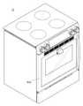
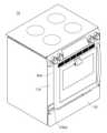
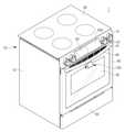
도 1은 본 발명의 일 실시예에 따른 오븐의 사시도이다.
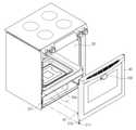
도 2는 본 발명의 일 실시예에 따른 도어가 개방된 상태를 도시한 도면이다.
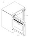
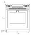
도 3은 본 발명의 일 실시예에 따른 오븐의 측단면도이다.
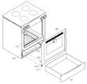
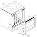
도 4는 본 발명의 일 실시예에 따른 오븐 본체와 모니터링 유닛이 분해된상태를 도시한 도면이다.
도 5는 본 발명의 일 실시예에 따른 모니터링 유닛의 확대 사시도이다.
도 6는 본 발명의 일 실시예에 따른 모니터링 유닛의 배면측 확대 사시도이다.
도 7은 본 발명의 일 실시예에 따른 모니터링 유닛의 분해 사시도이다.
도 8은 본 발명의 일 실시예에 따른 모니터링 유닛의 제 1하우징을 제거한 상태의 배면 사시도이다.
도 9는 본 발명의 일 실시예에 따른 모니터링 유닛의 촬영 범위를 개략적으로 도시한 도면이다.
도 10은 본 발명의 다른 일 실시예에 따른 모니터링 유닛의 제 1하우징을 제거한 상태의 배면 사시도이다.
도 11은 본 발명의 일 실시예에 따른 케이블의 전체적인 배치를 도시한 도면이다.
도 12는 본 발명의 일 실시예에 따른 측면패널이 제거된 상태에서 케이블이 케이스 측면에 배치되는 상태를 도시한 도면이다.
도 13은 본 발명의 일 실시예에 따른 케이블이 도어 내측에 배치되는 상태를 도시한 도면이다.
도 14은 본 발명의 일 실시예에 따른 케이블의 분리 구간의 확대도이다.
도 15는 본 발명의 일 실시예에 따른 케이블의 사시도이다.
도 16은 본 발명의 일 실시예에 따른 저장실이 제거된 상태의 전면도이다.
도 17는 본 발명의 일 실시예에 따른 저장실이 제거된 상태에서 도어가 케이스와 분리된 상태를 도시한 도면이다.
도 18은 본 발명의 다른 일 실시예에 따른 오븐의 사시도이다.
도 19는 본 발명의 다른 일 실시예에 따른 오븐의 도어가 개방된 상태를 도시한 도면이다.
도 20은 본 발명의 다른 일 실시예에 따른 오븐의 저장실이 제거된 상태의 전면도이다.
도 21은 본 발명의 다른 일 실시예에 따른 오븐의 사시도이다.
도 22는 본 발명의 다른 일 실시예에 따른 오븐의 도어가 분리된 상태의 분해 사시도이다.
도 23은 본 발명의 다른 일 실시예에 따른 오븐의 사시도이다.
도 24는 본 발명의 다른 일 실시예에 따른 오븐의 사시도이다.
도 25는 본 발명의 다른 일 실시예에 따른 오븐의 일부 구성이 분리된 상태의 분해 사시도이다.
도 26은 본 발명의 다른 일 실시예에 따른 오븐의 일부 구성이 분리된 상태의 분해 사시도이다.
도 27은 본 발명의 다른 일 실시예에 따른 오븐의 전면도이다.
도 28은 본 발명의 다른 일 실시예에 따른 오븐의 도어가 분리된 상태의 분해 사시도이다.
도 29는 본 발명의 다른 일 실시예에 따른 오븐의 전면도이다.
도 30은 본 발명의 다른 일 실시예에 따른 오븐의 일부 구성이 분리된 상태의 분해 사시도이다.
도 31은 본 발명의 다른 일 실시예에 따른 오븐의 일부 구성이 분리된 상태의 분해 사시도이다.
도 32는 본 발명의 일 실시예에 따른 오븐이 외부장치와 통신하는 상태를 개략적으로 도시한 도면이다.
도 33은 본 발명의 일 실시예에 따른 오븐이 외부장치로부터 정보를 수신받아 구동하는 상태를 단계적으로 도시한 도면이다.
도 34은 본 발명의 일 실시예에 따른 오븐이 외부장치로 정보를 송신하는 상태를 단계적으로 도시한 도면이다.
도 35는 본 발명의 다른 일 실시예에 따른 오븐의 사시도이다.
도 36은 본 발명의 다른 일 실시예에 따른 케이블이 도어 내측에 배치되는 상태를 도시한 도면이다.
도 37은 본 발명의 다른 일 실시예에 따른 오븐이 디스플레이모듈로부터 정보를 수신 받아 모니터링 유닛이 구동하는 상태를 단계적으로 도시한 도면이다.
도 38는 본 발명의 다른 일 실시예에 따른 오븐의 디스플레이모듈에 조리물의 영상이 표시되는 상태를 단계적으로 도시한 도면이다.1 is a perspective view of an oven according to an embodiment of the present invention.
2 is a view illustrating an open state of a door according to an embodiment of the present invention.
3 is a side cross-sectional view of an oven according to an embodiment of the present invention.
4 is a view showing a state in which the oven body and the monitoring unit are disassembled according to an embodiment of the present invention.
5 is an enlarged perspective view of a monitoring unit according to an embodiment of the present invention.
6 is an enlarged rear perspective view of a monitoring unit according to an embodiment of the present invention.
7 is an exploded perspective view of a monitoring unit according to an embodiment of the present invention.
8 is a rear perspective view illustrating a state in which the first housing of the monitoring unit is removed according to an embodiment of the present invention.
9 is a diagram schematically illustrating a photographing range of a monitoring unit according to an embodiment of the present invention.
10 is a rear perspective view illustrating a state in which the first housing of the monitoring unit is removed according to another embodiment of the present invention.
11 is a view illustrating an overall arrangement of cables according to an embodiment of the present invention.
12 is a view showing a state in which the cable is disposed on the side of the case in a state in which the side panel is removed according to an embodiment of the present invention.
13 is a view illustrating a state in which a cable is disposed inside a door according to an embodiment of the present invention.
14 is an enlarged view of a separation section of a cable according to an embodiment of the present invention.
15 is a perspective view of a cable according to an embodiment of the present invention.
16 is a front view of a state in which the storage compartment is removed according to an embodiment of the present invention.
17 is a view illustrating a state in which the door is separated from the case in a state in which the storage compartment is removed according to an embodiment of the present invention.
18 is a perspective view of an oven according to another embodiment of the present invention.
19 is a view showing an open state of the door of the oven according to another embodiment of the present invention.
20 is a front view of a state in which the storage compartment of the oven is removed according to another embodiment of the present invention.
21 is a perspective view of an oven according to another embodiment of the present invention.
22 is an exploded perspective view of a state in which the door of the oven is separated according to another embodiment of the present invention.
23 is a perspective view of an oven according to another embodiment of the present invention.
24 is a perspective view of an oven according to another embodiment of the present invention.
25 is an exploded perspective view illustrating a state in which some components of an oven are separated according to another embodiment of the present invention.
26 is an exploded perspective view illustrating a state in which some components of an oven are separated according to another embodiment of the present invention.
27 is a front view of an oven according to another embodiment of the present invention.
28 is an exploded perspective view of a state in which the door of the oven is separated according to another embodiment of the present invention.
29 is a front view of an oven according to another embodiment of the present invention.
30 is an exploded perspective view illustrating a state in which some components of an oven are separated according to another embodiment of the present invention.
31 is an exploded perspective view illustrating a state in which some components of an oven are separated according to another embodiment of the present invention.
32 is a diagram schematically illustrating a state in which the oven communicates with an external device according to an embodiment of the present invention.
33 is a diagram illustrating a state in which the oven is driven by receiving information from an external device according to an embodiment of the present invention in stages.
34 is a diagram illustrating a state in which the oven transmits information to an external device in stages according to an embodiment of the present invention.
35 is a perspective view of an oven according to another embodiment of the present invention.
36 is a view illustrating a state in which a cable is disposed inside a door according to another embodiment of the present invention.
37 is a diagram illustrating a state in which an oven receives information from a display module and a monitoring unit operates according to another embodiment of the present invention in stages.
38 is a diagram illustrating a state in which an image of food is displayed on a display module of an oven in stages according to another embodiment of the present invention.
본 명세서에 기재된 실시예와 도면에 도시된 구성은 개시된 발명의 바람직한 일 예에 불과할 뿐이며, 본 출원의 출원시점에 있어서 본 명세서의 실시예와 도면을 대체할 수 있는 다양한 변형 예들이 있을 수 있다.The configuration shown in the embodiments and drawings described in this specification is only a preferred example of the disclosed invention, and there may be various modifications that can replace the embodiments and drawings of the present specification at the time of filing of the present application.
또한, 본 명세서의 각 도면에서 제시된 동일한 참조번호 또는 부호는 실질적으로 동일한 기능을 수행하는 부품 또는 구성요소를 나타낸다.In addition, the same reference numerals or reference numerals in each drawing of the present specification indicate parts or components that perform substantially the same functions.
또한, 본 명세서에서 사용한 용어는 실시예를 설명하기 위해 사용된 것으로, 개시된 발명을 제한 및/또는 한정하려는 의도가 아니다. 단수의 표현은 문맥상 명백하게 다르게 뜻하지 않는 한, 복수의 표현을 포함한다. 본 명세서에서, "포함하다" 또는 "가지다" 등의 용어는 명세서상에 기재된 특징, 숫자, 단계, 동작, 구성요소, 부품 또는 이들을 조합한 것이 존재함을 지정하려는 것이지, 하나 또는 그 이상의 다른 특징들이나 숫자, 단계, 동작, 구성요소, 부품 또는 이들을 조합한 것들의 존재 또는 부가 가능성을 미리 배제하지 않는다.In addition, the terminology used herein is used to describe the embodiments, and is not intended to limit and/or limit the disclosed invention. The singular expression includes the plural expression unless the context clearly dictates otherwise. In the present specification, terms such as “comprise” or “have” are intended to designate that a feature, number, step, operation, component, part, or combination thereof described in the specification exists, but one or more other features It does not preclude the possibility of the presence or addition of numbers, steps, operations, components, parts, or combinations thereof.
또한, 본 명세서에서 사용한 " 제1","제2" 등과 같이 서수를 포함하는 용어는 다양한 구성요소들을 설명하는데 사용될 수 있지만, 상기 구성요소들은 상기 용어들에 의해 한정되지는 않으며, 상기 용어들은 하나의 구성요소를 다른 구성요소로부터 구별하는 목적으로만 사용된다. 예를 들어, 본 발명의 권리 범위를 벗어나지 않으면서 제1 구성요소는 제2 구성요소로 명명될 수 있고, 유사하게 제2 구성요소도 제1 구성요소로 명명될 수 있다. "및/또는"이라는 용어는 복수의 관련된 기재된 항목들의 조합 또는 복수의 관련된 기재된 항목들 중의 어느 항목을 포함한다.In addition, terms including an ordinal number such as "first", "second", etc. used herein may be used to describe various elements, but the elements are not limited by the terms, and the terms are It is used only for the purpose of distinguishing one component from another. For example, without departing from the scope of the present invention, a first component may be referred to as a second component, and similarly, a second component may also be referred to as a first component. The term “and/or” includes a combination of a plurality of related listed items or any of a plurality of related listed items.
이하에서는 본 발명에 따른 실시예를 첨부된 도면을 참조하여 상세히 설명한다.Hereinafter, an embodiment according to the present invention will be described in detail with reference to the accompanying drawings.
이하에서 사용되는 전면 및 전방은 도 1에 도시된 오븐(1)을 기준으로 앞으로 보이는 전면 및 전방을 향하는 방향을 지칭하고, 후방은 오븐(1)의 후방을 향하는 방향을 지칭하도록 한다.The front and front used below refer to the front and the forward facing directions with respect to the
도 1은 본 발명의 일 실시예에 따른 오븐의 사시도이고, 도 2는 본 발명의 일 실시예에 따른 오븐의 도어가 개방된 상태를 도시한 도면이고, 도 3은 본 발명의 일 실시예에 따른 오븐의 측단면도이다.1 is a perspective view of an oven according to an embodiment of the present invention, FIG. 2 is a view showing a state in which the door of the oven is opened according to an embodiment of the present invention, and FIG. 3 is an embodiment of the present invention It is a cross-sectional side view of the oven.
오븐(1, 또는 케이스 및 도어를 포함하는 본체, 이하에서는 통칭하여 오븐이라 한다.)은 외관을 형성하는 케이스(10)와 케이스(10) 내측으로 위치하는 조리실(20)과 오븐(1)의 상단에 마련되고 조리물이 담긴 용기를 올려 놓고 가열시킬 수 있는 쿡탑(30)을 포함할 수 있다.The oven (1, or a body including a case and a door, hereinafter collectively referred to as an oven) consists of a
케이스(10)는 케이스(10)의 전면을 형성하는 전면패널(11), 케이스(10)의 측면을 형성하는 측면패널(13) 및 케이스(10)의 후면을 형성하는 후면패널(14)을 포함할 수 있다.The
조리실(20)은 박스형태로 케이스(10) 내측으로 마련되고 조리물을 출납할 수 있도록 전면이 개방될 수 있다. 전면패널(11)에는 전면이 개방된 조리실(20)과 대응되게 마련되는 개구부(12)가 마련될 수 있다.The
조리실(20)의 개방된 전면은 도어(40)에 의해 개폐될 수 있다. 도어(40)는케이스(10)에 대해 회전 가능하도록 케이스(10) 하측에 힌지 결합될 수 있으며, 도어(40)에는 사용자가 파지할 수 있는 손잡이(41)가 마련될 수 있다.The opened front side of the
도어(40)는 조리실(20) 내부의 조리물의 조리 과정을 외부에서 확인할 수 있도록 유리 등의 투명한 재질로 마련되는 투시부(42)를 포함할 수 있다.The
도어(40)의 내측으로는 복수의 유리부재(43)가 마련될 수 있다. 이는 투시부(42)를 통해 조리실(20)의 내부를 볼 수 있게 하기 위함으로 유리 이외에 투명한 부재로 마련될 수 있다.A plurality of
도어(40)의 하단에는 도어(40) 내측으로 공기를 흡입할 수 있는 도어 흡입구(44)가 마련될 수 있다. 조리실(20)에서 발생하는 열기가 도어(40) 외측면으로 전달되지 않도록 공기의 순환을 통해 도어(40) 내부의 열을 냉각시키기 위함이다.A
도어(40) 하단에서 유입된 외기는 도어(40)의 상측으로 이동하면서 조리실(20)에서 전달되는 열기와 열교환 된 후 도어(40) 전방에 위치하는 도어 토출구(45)에 의해 토출될 수 있다.The outside air introduced from the lower end of the
조리실(20)의 하측에는 조리 용기 등을 보관할 수 있는 저장실(50)이 마련될 수 있다. 저장실(50)은 슬라이딩 이동으로 오븐(1)의 전후방으로 인입 및 인출 가능하게 마련될 수 있다.A
조리실(20)의 내부에는 복수의 지지대(21)가 마련될 수 있다. 복수의 지지대(21)에는 조리물을 올려 놓을 수 있는 랙(23)을 장착할 수 있다. 복수의 지지대(21)는 조리실(20)의 좌측벽과 우측벽에서 돌출되도록 마련될 수 있다.A plurality of
복수의 지지대(21)에는 조리실(20)을 분할할 수 있는 디바이더(미도시)가 분리 가능하도록 장착될 수 있다. 구체적으로, 디바이더(미도시)는 조리실(20)에 수평하게 장착되어, 조리실(20)을 복수개로 분할할 수 있다.A divider (not shown) capable of dividing the
복수의 조리실(20)은 각각의 크기가 서로 동일해야 하는 것은 아니며, 각각의 크기가 서로 상이할 수도 있다. 디바이더(미도시)는 단열 재질을 가지고, 각각의 조리실(20)을 단열시킬 수 있다. 이를 통해 사용자의 의도에 따라 조리실(20)을 공간을 다양하게 활용할 수 있다.Each of the plurality of
조리실(20)에는 조리물을 가열시키는 히터(22)가 마련될 수 있다. 본 실시예에서 히터(22)는 전기 저항체를 포함하는 전기 히터일 수 있다. 다만, 본 실시예와 달리 히터(22)는 가스를 연소시켜 열을 발생시키는 가스 히터일 수도 있다. 즉, 본 발명의 실시예에 따른 오븐(1)은 전기 오븐 및 가스 오븐을 포함한다.A
조리실(20)의 후방에는 조리실(20)의 공기를 순환시켜 조리물이 골고루 가열되도록 하는 순환 팬(25)과, 순환 팬(25)을 구동시키는 순환 모터(24)가 마련될 수 있다. 순환 팬(25)의 전방에는 순환 팬(25)을 커버하는 팬 커버(26)가 마련될 수 있으며, 팬 커버(26)에는 공기가 유동될 수 있도록 통공(27)이 형성된다.A
전면패널(11)의 전면 상부에는 오븐(1)의 각종 동작 정보를 표시하고, 사용자가 동작 명령을 입력할 수 있는 디스플레이 모듈(60)이 마련될 수 있다. 디스플레이 모듈(60)은 전장실 커버(15)에 장착될 수 있다.A
또한 전장실 커버(15)에는 오븐(1)을 추가적으로 동작시키도록 마련되는 조작부(61)가 마련될 수 있다.In addition, an
오븐(1)은 디스플레이 모듈(60)을 포함한 각종 부속품의 동작을 제어하는 전장품을 수용하는 전장실(70)을 갖는다. 전장실(70)의 조리실(20)의 상부에 마련된다. 전장실(70)과 조리실(20)의 사이에는 조리실(20)의 열기가 전장실(70)에 전달되는 것을 방지하도록 전장실(70)과 조리실(20)을 단열하는 단열재(71)가 마련될 수 있다.The
또한 단열재(71)는 전장실(70)과 조리실(20) 뿐만 아니라 조리실(20)의 열기가 오븐(1) 외측으로 전달되지 않도록 조리실(20) 외측을 전체적으로 커버할 수 있도록 마련될 수 있다.In addition, the
오븐(1)은 조리실(20) 주위에 공기를 순환시킴으로써 전장실(70)을 냉각시키는 냉각 구조를 갖는다. 오븐(1)의 냉각 구조는 공기를 유동시키는 냉각팬 유닛(72)과, 냉각팬 유닛(72)에 의해 흡입된 공기를 오븐(1)의 전방으로 토출시키는 냉각 유로(73)를 포함할 수 있다.The
즉, 본체 외부의 공기는 후면패널(14)에 형성된 통공(14a)을 통해 전장실(70)로 흡입되고, 전장실(70)로 흡입된 공기는 전장실(70) 내부를 유동하며 전장품을 냉각시킨 후에 냉각 유로(73)를 따라 토출구(74)를 통해 오븐(1)의 전방으로 최종적으로 토출될 수 있다.That is, the air outside the main body is sucked into the
조리실(20)의 일부 공기는 배기유로(75)를 통해 냉각 유로(73)측으로 흡입되어 오븐(1)의 전방으로 토출될 수 있다. 또한 냉각 유로(73)에서 토출구(74)로 유동하는 공기의 일부를 배기 유로(75)로 유입시키는 바이패스 홀(76)이 추가로 형성될 수 있다. 바이패스 홀(76)은 개폐 장치(77)에 의해 개폐되고, 바이패스 홀(76)의 개폐에 따라 냉각 유로(75)로 배기되는 조리실(20)의 공기의 배기량이 조절될 수 있다.Part of the air in the
이하에서는 조리실(20) 내부를 촬영하는 모니터링 유닛(100)에 대하여 자세히 설명한다.Hereinafter, the
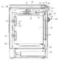
도 4는 본 발명의 일 실시예에 따른 오븐 본체와 모니터링 유닛이 분해된상태를 도시한 도면이고, 도 5는 본 발명의 일 실시예에 따른 모니터링 유닛의 확대 사시도이고, 도 6는 본 발명의 일 실시예에 따른 모니터링 유닛의 배면측 확대 사시도이고, 도 7은 본 발명의 일 실시예에 따른 모니터링 유닛의 분해 사시도이고, 도 8은 본 발명의 일 실시예에 따른 모니터링 유닛의 제 1하우징을 제거한 상태의 배면 사시도이고, 도 9는 본 발명의 일 실시예에 따른 모니터링 유닛의 촬영 범위를 개략적으로 도시한 도면이다.Figure 4 is a view showing a state in which the oven body and the monitoring unit are disassembled according to an embodiment of the present invention, Figure 5 is an enlarged perspective view of the monitoring unit according to an embodiment of the present invention, Figure 6 is a view of the present invention A rear enlarged perspective view of the monitoring unit according to an embodiment, FIG. 7 is an exploded perspective view of the monitoring unit according to an embodiment of the present invention, and FIG. 8 is a first housing of the monitoring unit according to an embodiment of the present invention It is a rear perspective view of the removed state, and FIG. 9 is a view schematically illustrating a photographing range of a monitoring unit according to an embodiment of the present invention.
도 4 및 도5에 도시된 바와 같이 모니터링 유닛(100)은 도어(40)의 외측면에 배치될 수 있다. 자세하게는 도어(40)에 마련되는 투시부(42)의 외측면에 마련되어 투시부(42)를 통해 도어(40) 외측에서 투시부(42)를 투과하여 조리실(20)내부를 촬영할 수 있다.As shown in FIGS. 4 and 5 , the
상술한 바와 같이 투시부(42)는 투명한 재질로 마련되고, 도어(40)의 내측에 투시부(42)와 대응되는 위치에는 복수의 유리부재(43)가 마련되어 투시부(42)의 외측에 모니터링 유닛(100)이 위치할 경우 조리실(20) 내부나 도어(40) 내부에 위치하지 않아도 조리실(20) 내부를 촬영할 수 있다.As described above, the see-through
조리실(20) 내부에 모니터링 유닛(100)이 위치할 경우, 조리실(20)은 조리시 대략 200도의 온도를 유지하며, 조리실(20) self clean 시 450도까지 온도가 상승하는 바 모니터링 유닛(100)은 높은 내열성이 요구된다.When the
이를 방지하기 위해 모니터링 유닛(100)은 도어(40)의 외측에 배치하게 된다. 도어(40)의 외측에 전달되는 열은 최대 65도 정도로 큰 내열성을 요구하지 않아 내열을 위한 추가 구성이나 특수한 내열 공법이 필요하지 않아 제품 생산의 경제적인 측면에서 효율적이다.To prevent this, the
본 발명의 일 실시예와 달리 모니터링 유닛(100)은 도어(40)가 아닌 케이스(10)의 일측에도 배치될 수 있으며, 모니터링 유닛(100)이 마련되는 위치에는 조리실(20) 내부가 투시 가능한 추가적인 투시부(42)가 마련될 수 있다.Unlike the exemplary embodiment of the present invention, the
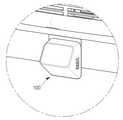
투시부(42)의 일측에는 모니터링 유닛(100)이 배치되는 위치와 대응되게 대응부(42a)가 마련될 수 있다. 대응부(42a)는 모니터링 유닛(100)이 배치되는 위치에 대응되게 마련될 뿐 특정한 위치에 마련되어야 하는 것은 아니다.A
모니터링 유닛(100)은 모니터링 유닛(100)의 카메라모듈(110)의 최대 촬영 각도(카메라의 최대 화각)를 고려하여 조리실(20)의 내부가 모두 촬영될 수 있는 위치에 배치될 수 있다.The
카메라모듈(110)의 최대 촬영 각도 및 조리실(20)의 크기에 따라 별도로 대응부(42a)가 마련되지 않고 투시부(42) 외측면의 일측에 마련될 수 있다.Depending on the maximum photographing angle of the
모니터링 유닛(100)은 조리실(20) 내부를 촬영하는 카메라모듈(110), 카메라모듈(110)에서 촬영된 정보를 외부 장치에 송신하고 외부 장치로부터 정보를 수신 받을 수 있는 통신보드(120), 카메라모듈(110)을 냉각하는 냉각팬(130) 및 모니터링 유닛(100)의 외관을 형성하는 하우징(140,150)으로 구성될 수 있다.The
카메라모듈(110)은 이미지 촬영 및 동영상 촬영이 가능한 카메라(112)와 전원을 공급받고 전기적인 정보가 송수신되도록 후술할 케이블(200)과 연결되는 커넥터(113) 및 카메라(112)와 커넥터(113) 외 기타 전자부품들이 안착되는 카메라보드(111)를 포함할 수 있다.The
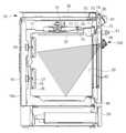
카메라(112)는 투시부(42)를 투시하여 조리실(20)의 내부 모습을 관측할 수 있다. 카메라(112)는 바람직하게는 상하측으로 60도 내외의 촬영 각도를 가질 수 있으며 좌우측으로 100도 내외의 촬영 각도를 가질 수 있다.The
카메라(112)의 최대 촬영 각도에 따라 카메라모듈(110)이 배치되는 각도가 정해질 수 있다. 최대 촬영 각도 안에 조리실(20) 내부가 모두 들어올 수 있게 카메라모듈(110)은 도어(40)의 내측면에 대해 경사를 두고 배치될 수 있다.An angle at which the
바람직하게는 투시부(42)의 상측에 투시부(42)와 소정의 각도를 두고 기울게 배치될 수 있다(도 9 참고).Preferably, the see-through
통신보드(120)는 카메라모듈(110)에서 발생한 조리실(20) 내부의 이미지 정보 또는 동영상 정보를 외부 장치에 전송할 수 있다. 통신보드(120)는 다양한 통신 방법을 통해 외부 장치에서 발생하는 정보를 송신하고 외부 장치로부터 정보를 수신받을 수 있다.The
예를 들어, 3G(3Generation), 4G(4Generation) 등과 같은 통신방식을 통해 무선 신호를 송수신할 수 있으며, 이외에도 무선 랜(Wireless LAN), 와이파이(Wi-Fi), 블루투스(Bluetooth), 지그비(Zigbee), WFD(Wi-Fi Direct), UWB(Ultra wideband), 적외선 통신(IrDA; Infrared Data Association), BLE (Bluetooth Low Energy), NFC(Near Field Communication) 등과 같은 통신방식을 통해 소정 거리 이내에서 정보를 송수신할 수도 있다.For example, wireless signals can be transmitted and received through communication methods such as 3G (3Generation) and 4G (4Generation), and in addition, wireless LAN, Wi-Fi, Bluetooth, and Zigbee ), WFD (Wi-Fi Direct), UWB (Ultra wideband), Infrared Data Association (IrDA), BLE (Bluetooth Low Energy), NFC (Near Field Communication), etc. can also be sent and received.
통신보드(120)는 경우에 따라 모니터링 유닛(100) 외 케이스(10) 내부에 마련될 수 있다. 오븐(1)의 케이스(10)는 내열성을 확보하기 위해 통상적으로 스틸을 포함되는 부재로 마련되어 통신보드(120)가 스틸을 포함하는 부재 내측에 마련될 경우 통신의 제한을 받을 수 있어 케이스(10) 외측에 마련되는 모니터링 유닛(100)에 마련되는 것이 바람직하다.The
통신보드(120)의 정보 송수신에 대해서는 자세하게 후술한다.Information transmission and reception of the
카메라모듈(110)의 일측에는 카메라모듈(110)을 냉각시키는 냉각팬(130)이 마련될 수 있다. 모니터링 유닛(100)은 조리실(20)의 열의 일부가 전달되는 도어(40)와 접하게 마련될 수 있어 상온보다 높은 온도에 마련될 수 있다.A cooling
냉각팬(130)은 카메라모듈(110) 자체에서 발생하는 열과 모니터링 유닛(100) 외측에서 발생하는 상온보다 높은 온도(대략 65도 정도)를 냉각시켜 카메라모듈(110)이 안정적으로 구동될 수 있게 한다.The cooling
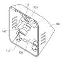
모니터링 유닛(100)의 외관을 이루는 하우징(140, 150)은 카메라모듈(110)과 통신보드(120)가 안착되는 제 1하우징(140)과 도어(40)의 외측면에 접하는 제 2하우징(150)으로 구성될 수 있다.The
제 1하우징(140)은 내측으로 카메라모듈(110)과 통신보드(120)가 안착되도록 일측으로 개구를 가지는 공간을 포함할 수 있다. 자세하게는 제 1하우징(140)의 내측에는 카메라모듈(110)이 안착되는 제 1안착부(141)와 통신보드(120)가 안착되는 제 2안착부(142)를 포함할 수 있다.The
카메라모듈(110)은 상술한 바와 같이 도어(40)에 대하여 일정 경사를 두고 배치되는 바 제 1안착부(141)는 카메라모듈(110)의 경사와 대응되는 경사로 마련될 수 있다.The
제 1안착부(141)의 제 2안착부(142)와 인접한 일측은 제 2안착부(142) 측에서 제 1안착부(141)측으로 돌출되고 카메라모듈(110)이 제 1안착부(141)에 평행하게 지지될 수 있도록 카메라모듈(110)의 하측과 접하는 제 1지지돌기(143)와 제 1지지돌기(143)에 안착된 카메라모듈(110)을 고정시키는 제 1고정후크(144)를 포함할 수 있다.One side of the
도 7에는 도시되어 있지 않지만 제 1안착부(141)의 상측에는 제 1지지돌기(143)과 제 1고정후크(144)와 유사한 구성이 마련되어 카메라모듈(110)의 상측을 지지할 수 있다.Although not shown in FIG. 7 , a configuration similar to that of the
제 2안착부(142)는 제 2안착부(142)에서 상측으로 돌출되는 제 2지지돌기(145)를 포함하여 통신보드(120)의 하측을 지지할 수 있다. 또한 제 1하우징(140)의 한 쌍의 측부에서 내측으로 돌출되는 제 2고정후크(146)가 마련되어 제 2지지돌기에 지지되는 통신보드(120)를 고정시킬 수 있다.The
제 1,2지지돌기(143,145)와 제 1,2고정후크(144,146)는 본 발명의 일 실시예에 한정되지 않고 카메라모듈(110)과 통신보드(120)가 제 1하우징(140)에 안착될 수 있도록 다양한 형상으로 마련될 수 있다.The first and
통신보드(120)는 제 2안착부(142)와 최대한 인접하게 마련될 수 있다. 자세하게는 통신보드(120)와 제 2안착부(142)가 마련되는 제 1하우징 사이에는 다른 구성이 마련되지 않을 수 있다.The
통신보드(120)가 외부 장치로 정보를 송수신함에 있어서 통신에 방해되지 않게 하기 위함이다. 이와 같은 이유로 모니터링 유닛(100)의 일부가 본 발명의 일실시예와 달리 도어(40)의 내측 또는 케이스(10)의 내측에 배치된다고 해도 통신보드는 도어(40)의 외측 또는 케이스(10)의 외측에 배치될 수 있다.This is to prevent the
제 1하우징(140)의 개구 상측에는 제 2하우징(150)과 결합 가능하도록 마련되는 제 1결합후크(147)이 마련될 수 있다. 제 1결합후크(147)는 제 2하우징(150)에 마련되는 제 1결합홈(154)과 대응되게 마련되어 제 1하우징(140)과 제 2하우징(150)이 대응되게 접할 시 제 1결합홈(154)에 삽입되어 결합될 수 있다.A
또한 제 1하우징(140)의 개구 하측에는 제 2하우징(150)과 결합 가능하도록 마련되는 제 2결합홈(148)이 마련될 수 있다. 제 2결합홈(148)은 제 2하우징(150)에 마련되는 제 2결합후크(153)과 대응되게 마련된다.In addition, a
제 1,2결합후크(147,153) 및 제 1,2결합홈(154,148)은 본 발명의 일 실시예에 한정되지 않고 상하 위치가 반대로 형성될 수 있다.The first and second coupling hooks 147 and 153 and the first and
제 2하우징(150)은 상술한 바와 같이 제 1하우징(140)과 분리 가능하게 마련되며, 도어(40)에 결합 가능하게 마련될 수 있다.As described above, the
제 2하우징(150)은 플레이트 형상으로 마련되어 도어(40)와 마주하는 측에 설치면(150a)을 포함한다. 설치면(150a)은 도어(40)와 평행하게 마련되고 접착제 등에 의해 도어(40) 외측면에 부착될 수 있으며, 별도의 설치부재(예를 들어 나사에 의한 결합이나, 후크에 의한 결합)에 의해 도어(40)의 외측면에 결합될 수 있다.The
제 2하우징(150)은 제 1하우징(140)에 안착된 카메라모듈(110)이 제 2하우징(150)을 투과하여 조리실(20) 내부를 촬영할 수 있도록 개방된 개방부(151)를 포함할 수 있다.The
개방부(151)는 카메라모듈(110)의 설치 각도 및 카메라(112)의 촬영 각도를 고려하여 그 크기를 결정할 수 있다.The size of the
제 2하우징(150)의 일측에는 카메라 유닛(100)과 후술할 마이컴(300)을 전기적으로 연결하는 케이블(200)이 모니터링 유닛(100)의 내측으로 연결되는 케이블 관통공(152)이 마련될 수 있다.A cable through
케이블 관통공(152)은 케이블(200)이 도어(40) 내측에서 외측으로 관통될 수 있게 마련되는 도어 관통공(46)과 대응되는 위치에 마련될 수 있다(도4 참조). 마이컴(300)에서부터 연결된 케이블(200)은 도어(40) 내측을 거쳐 도어 관통공(46)과 케이블 관통공(152)을 투과하여 모니터링 유닛(100)의 내측으로 연결될 수 있다.The cable through
케이블 관통공(152)의 내측에는 실링부재(156)이 마련될 수 있다. 케이블 관통공(152)과 케이블(200) 사이에 마련되는 이격을 차단하여 도어(40)에서 발생하는 열이 모니터링 유닛(100) 내측으로 전달되는 것을 방지하기 위함이다.A sealing
제 2하우징(150)의 제 1하우징(140)과 마주하는 측에는 냉각팬(130)이 배치될 수 있도록 냉각팬 지지돌기(155)가 마련될 수 있다.A cooling
냉각팬(130)이 카메라모듈(110)과 인접하고 카메랑모듈(110)과 수평하게 마련되어 냉각효율을 높이기 위해 냉각팬 지지돌기(155)는 냉각팬(130)이 카메라모듈(110)과 동일한 경사로 배치될 수 있도록 제 2하우징(150)에 대해 소정의 경사를 가지고 제 1하우징(140) 측으로 돌출될 수 있다.The cooling
모니터링 유닛(100)의 설치 순서는 먼저 모니터링 유닛(100)을 도어 관통공(46)과 케이블 관통공(152)이 대응되는 위치(대응부(42a))에 위치시키고 설치면(150a)이 도어(40)에 접하도록 부착한다.The installation sequence of the
이 후 카메라모듈(110)과 통신보드(120)가 안착된 제 1하우징(140)을 제 2하우징(150)과 대응되게 위치시키고 마주하는 측으로 가압하여 후킹되게 한다.After that, the
하우징(140,150)이 결합된 후, 하우징(140,150) 내측에 마련되는 구성들을 교환하도록 하우징(140,150)은 반대측으로 가압하여 분리되게 마련될 수 있다. 즉, 제 2하우징(150)을 반대로 가압하여 제 1하우징(140)으로부터 착탈시킬 수 있다.After the
또한 제 1하우징(140)의 일측에 소정의 크기로 개구(미도시)를 마련하여 제 1하우징(140)과 제 2하우징(150)을 분리하지 않고 개구(미도시)를 통해서 내부 구성을 교환할 수 있다. 이 때 개구(미도시)는 별도의 패킹부재(미도시)에 의해 폐쇄하도록 마련되어 내부 구성을 교환할 때만 개방할 수 있게 마련될 수 있다.In addition, an opening (not shown) of a predetermined size is provided on one side of the
상술한 바와 같이 통신보드(120)의 통신 제한을 방지하기 위해 하우징(140,150)는 플라스틱 수지 등을 포함하는 재질로 마련되는 것이 바람직히다.As described above, in order to prevent communication limitation of the
도 10은 본 발명의 다른 일 실시예에 따른 따른 모니터링 유닛의 제 1하우징을 제거한 상태의 배면 사시도이다. 이하에서 별도로 설명하는 구성 외의 구성은 상술한 오븐(1)의 구성과 동일하다.10 is a rear perspective view illustrating a state in which the first housing of the monitoring unit is removed according to another embodiment of the present invention. Configurations other than the configuration described separately below are the same as the configuration of the
카메라(112')는 회전부재(112a)에 의해 회전 가능하게 마련될 수 있다.The camera 112' may be rotatably provided by the rotating
회전부재(112a)는 카메라(112')와 카메라 보드(111) 사이에 마련되어 회전부재(112a)의 회동에 의해 카메라(112')가 회전될 수 있도록 마련된다. 회전부재(112a)는 힌지 구조로 마련되어 카메라(112')가 상하 또는 좌우로 틸팅되게 할 수 있으며, 볼 구조로 마련되어 카메라(112')가 자유롭게 회전되게 마련될 수 있다.The rotating
카메라(112')가 회전이 가능함에 따라 카메라(112')가 촬영할 수 있는 범위가 넓어질 수 있으며, 조리물이 위치하는 랙(23)의 높이에 맞게 카메라(112')가 회전되어 촬영할 수 있어 사용자의 요구에 대응되는 선명한 영상 정보를 획득할 수 있다.As the camera 112' is rotatable, the range that the camera 112' can shoot can be widened, and the camera 112' can be rotated to fit the height of the
이하에서는 마이컴(300)과 모니터링 유닛(100)을 전기적으로 연결하는 케이블(200)에 대하여 자세히 설명한다.Hereinafter, the
도 11은 본 발명의 일 실시예에 따른 케이블의 전체적인 배치를 도시한 도면이고, 도 12는 본 발명의 일 실시예에 따른 측면패널이 제거된 상태에서 케이블이 케이스 측면에 배치되는 상태를 도시한 도면이고, 도 13은 본 발명의 일 실시예에 따른 케이블이 도어 내측에 배치되는 상태를 도시한 도면이고, 도 14은 본 발명의 일 실시예에 따른 케이블의 분리 구간의 확대도이고, 도 15는 본 발명의 일 실시예에 따른 케이블의 사시도이고, 도 16은 본 발명의 일 실시예에 따른 저장실이 제거된 상태의 전면도이고, 도 17는 본 발명의 일 실시예에 따른 저장실이 제거된 상태에서 도어가 케이스와 분리된 상태를 도시한 도면이다.11 is a view showing the overall arrangement of a cable according to an embodiment of the present invention, and FIG. 12 is a view showing a state in which the cable is arranged on the side of the case with the side panel removed according to an embodiment of the present invention FIG. 13 is a view showing a state in which a cable is disposed inside a door according to an embodiment of the present invention, FIG. 14 is an enlarged view of a separation section of a cable according to an embodiment of the present invention, and FIG. 15 is a perspective view of a cable according to an embodiment of the present invention, Figure 16 is a front view of a state in which the storage compartment is removed according to an embodiment of the present invention, Figure 17 is a storage compartment according to an embodiment of the present invention is removed It is a view showing a state in which the door is separated from the case in the state.
오븐(1)은 모니터링 유닛(100)을 제어하는 마이컴(300)을 포함할 수 있다.The
마이컴(300)은 모니터링 유닛(100)만 독립적으로 제어하는 구성으로 마련될 수 있으며, 전체 오븐(1)의 구동을 제어하면서 추가적으로 모니터링 유닛(100) 제어하는 구성일 수 있다. 이하에서 마이컴(300)은 모니터링 유닛(100) 및 오븐(1)을 제어하는 구성으로 설명한다.The
또한 마이컴(300)은 칩으로 형성되는 마이크로컴퓨터 및 미이크로컴퓨터가 장착되는 기판과 기판에 장착되는 전원공급부 등의 각종 마이크로컴퓨터를 구동시키는 각종 전장품을 모두 포함하는 구성으로 정의한다.In addition, the
마이컴(300)과 모니터링 유닛(100) 사이에는 케이블(200)이 연결될 수 있다. 케이블(200)은 마이컴(300)과 모니터링 유닛(100)이 전기적으로 연결되게 할 수 있다.A
케이블(200)은 모니터링 유닛(100)에 전원을 공급하고 마이컴(300)과 모니터링 유닛(100)간에 정보를 송수신 하는 역할을 수행할 수 있다.The
마이컴(300)은 오븐(1)의 후면 패널(14) 내측에 마련될 수 있다. 이에 따라 케이블(200)은 후면패널(14)의 내측에서부터 측면패널(13)의 내측을 통과한다.The
자세하게는 도 12에 도시된 바와 같이 마이컴(300)에서부터 연결되는 케이블(200)은 후면패널(14) 내측에서 측면패널(13) 내측방향으로 절곡되고 저장실(50)과 대응되는 높이에서 오븐(1)의 전방방향으로 다시 절곡되어 전면패널(11)을 향하게 배치된다.In detail, as shown in FIG. 12 , the
측면패널(13)의 내측에서는 단열재(71)가 마련되는 공간과 측면패널(13)이 마련되는 공간 사이, 즉 단열재(71)를 포함하는 조리실(20)의 최외곽부와 측면패널(13) 사이(20a)와 저장실(50)과 측면패널(13)의 사이(50a)로 관통될 수 있도록 배치된다. 이는 케이블(200)이 고장날 경우 케이블(200)의 교체를 용이하게 하기 위함이다.In the inner side of the
케이블(200)이 마이컴(300)에서부터 전면패널(11)로 연장되는 구간에서 케이블(200)은 케이스(10) 내측에 마련되는 오븐(1)의 임의적인 구성에 고정되어 지지될 수 있도록 마련되는 복수의 고정부재(250)에 의해 고정될 수 있다.In a section in which the
고정부재(250)는 케이블(200)이 관통되어 지지될 수 있도록 마련되는 지지공을 포함할 수 있다. 지지공은 케이블(200)과 지지공 사이에 어느 정도의 이격을 두어 케이블(200)이 유동될 수 있도록 케이블(200)의 지름보다 큰 지름을 가지도록 마련될 수 있다.The fixing
고정부재(250)는 오븐(1)의 어떤 구성이든 가변적으로 부착되어 케이블(200)을 지지할 수 있다.The fixing
측면패널(13)의 내측에 배치되는 케이블은 전면패널(11)의 내측으로 연장되지 않고 전면패널(11)을 관통하여 도어(40)의 내측으로 연장되어 모니터링 유닛(100)으로 연결된다. 이는 도어(40)가 오븐(1)에 대해 분리 시 케이블(200)을 용이하게 분리시키기 위함이다.The cable disposed inside the
케이블(200)에 있어서 모니터링 유닛(100)에 연결되고 도어(40)을 내측에 배치되는 케이블(200)의 구간을 제 1케이블(210)이라하고 제 1케이블(210)에서 연장되어 마이컴(300)과 연결되고 케이스(10)의 내측에 배치되는 케이블(200)의 구간을 제 2케이블(220)이라고 할 때, 제 1케이블(210)과 제 2케이블(220) 사이에는 케이블(200)이 분리될 수 있도록 분리 구간(230)이 마련될 수 있다.In the
제 1케이블(210)은 일측이 모니터링 유닛(100)과 연결될 될 수 있다. 자세하게는 도어(40) 내측에 배치되어 도어(40)의 외측면에 위치한 도어 관통공(46)을 관통하여 모니터링 유닛(100) 내측으로 연장될 수 있다.One side of the
제 1케이블(210)은 모니터링 유닛(100)의 케이블 관통공(152)을 통과하여 카메라모듈(110)의 커넥터(113)과 연결될 수 있다.The
도 13에 도시된 바와 같이 제 1케이블(210)은 미관상의 이유로 투시부(42)에 대응되지 않는 도어(40)의 내측에 배치될 수 있다. 따라서 도어 관통공(46)에서 연장된 제 1케이블은 수평방향으로 연장되고 도어(40)의 측부에서 절곡되어 하측으로 연장될 수 있다.As shown in FIG. 13 , the
제 1케이블(210)은 상술한 고정부재(250)에 의해 도어(40)의 내측에 고정되어 배치될 수 있다.The
도어(40)의 하측 방향으로 연장되는 제 1케이블(210)의 타측은 도어(40)의 하면을 관통하여 도어(40)의 외부에 노출되어 연장되게 마련되는 노출부(215)를 포함할 수 있다. 노출부(215)의 일단, 즉 제 1케이블(210)의 타측은 전면패널(11)에 위치하는 제 2케이블(220)과 연결될 수 있다.The other side of the
제 2케이블(220)은 일측이 후면패널(14) 측에 마련되는 마이컴(300)에 연결될 수 있다. 제 2케이블(220)은 상술한 바와 같이 마이컴(300)에서부터 연장되어 후면패널(14) 및 측면패널(13)의 내측으로 연장된다.One side of the
제 2케이블(220)의 타측은 전면패널(11)에 배치되어 제 1케이블(210)과 연결될 수 있다. 자세하게는 제 2케이블(220)의 타단이 전면패널(11)의 후방에서 관통되어 전면패널(11)의 전방에 위치하게 마련되어 제 2케이블(220)의 타단이 전면패널(11) 상에 위치할 수 있다.The other side of the
제 1케이블(210)과 제 2케이블(220) 사이에는 분리 구간(230)이 마련될 수 있다. 자세하게는 제 1케이블(210)과 제 2케이블(220)이 연결되는 전면패널(11) 상에 마련되며 도어(40)의 하측에 위치할 수 있다.A
분리 구간(230)에서 제 1케이블(210)과 제 2케이블(220)은 분리될 수 있다. 자세하게는 제 1케이블(210)의 타측에는 제 2케이블(220)과 결합되는 제 1결합부(211)가 마련되며 제 2케이블(220)의 일측에는 제 1케이블(210)의 제 1결합부(211)과 결합되는 제 2결합부(221)이 마련되어 결합될 수 있다.In the
제 1결합부(211)는 USB 커넥터 형상으로 마련되고 제 2결합부(221)는 USB 포트 형상으로 마련되어 제 1결합부(211)가 제 2결합부(221)에 삽입되는 형식으로 결합될 수 있다.The
제 2결합부(221)는 전면패널(11)상에 나사 등에 의해 결합될 수 있고 이에 따라 제 1결합부(211)가 전면패널(11)에 삽입되는 형식으로 케이블(200)의 결합/분리가 가능하게 마련될 수 있다.The
분리 구간(230)은 노출부(215)의 일단과 대응되게 마련되는 바 도어(40)의 하측에 위치하고, 이는 저장실(50)의 높이상의 일측에 마련될 수 있다.The
따라서 저장실(50)이 닫혀있을 시에는 저장실(50)의 전면부에 의해 분리 구간이(230) 오븐(1)의 외부에 노출되지 않고, 저장실(50)이 슬라이딩 개방될 때 외부에 노출된다.Therefore, when the
이 때 사용자가 용이하게 제 1케이블(210)과 제 2케이블(220) 사이를 가압할 수 있어 케이블(200)이 분리될 수 있다.At this time, the user can easily press between the
사용자는 필요에 따라 도어(40)의 청소 시 도어를 케이스(10)에 대해 분리할 수 있는데, 케이블(200)은 도어(40)가 케이스(10)와 분리될 시 분리 구간(230)에서 제 1케이블(210)과 제 2케이블(220)이 분리되어 도어(40)와 같이 케이스(10)로부터 분리될 수 있다.The user can separate the door from the
모니터링 유닛(100)이 도어 상에 마련되어 있어, 도어(40)의 분리 시 모니터링 유닛(100)도 케이스(10)에 대해 분리될 수 있다. 이 때, 모니터링 유닛(100)은 케이블(200)에 의해 마이컴(300)과 연결되어 있어 케이블(200)이 분리되지 않을 경우, 도어(40)가 분리되어도 케이스(1)의 내측으로 연장되게 마련되는 케이블(200)의 일부에 의해 도어(40)가 케이스(10)로부터 완전히 분리될 수 없다.Since the
따라서 분리 구간(230)은 사용자로 하여금 도어(40)를 케이스(10)로부터 완전하게 분리할 수 있게 하는 역할을 한다.Accordingly, the
제 1케이블(210) 일측에는 모니터링 유닛(100)의 커넥터(113)과 연결되는 제 1연결부(212)가 마련되어 제 1케이블(210)과 모니터링 유닛(100)이 전기적으로 연결될 수 있게 한다.A
제 2케이블(220) 타측에는 마이컴(300)에 연결되는 제 2연결부(222)가 마련되어 제 2케이블(220)과 마이컴(300)이 전기적으로 연결될 수 있게 한다.A
자세하게는 상술한 바와 같이 제 1케이블(210)의 타측에 마련된 제 1결합부(211)와 제 2케이블(220)의 제 2결합부(221)가 결합되어 마이컴(300)과 모니터링 유닛(100)이 전기적으로 연결될 수 있다.In detail, as described above, the
이하에서는 도어(40)가 케이스(10)에 대해 분리됨에 따라 케이블(200)이 분리되는 과정을 설명한다.Hereinafter, a process in which the
도어(40)를 분리하기 전에 선행적으로 저장실(50)을 슬라이딩 개방하여 케이블(200)의 분리 구간(230)을 개방하여야 한다. 저장실(50)이 닫혀있는 경우 사용자가 분리 구간(230)에 접근하기 어려워 케이블(200)을 분리할 수 없고, 이에 따라 케이블(200)이 케이스(10) 내측과 연결되는 상태가 유지되어 도어(40)가 완전하게 케이스(10)에서 분리될 수 없기 때문이다.Before removing the
도 15 및 도 16에 도시된 바와 같이 저장실(50)이 개방된 경우 도어(40) 하측으로는 케이블(200)의 노출부(215) 및 노출부(215) 상에 위치하는 분리 구간(230)이 노출될 수 있다.As shown in FIGS. 15 and 16 , when the
사용자는 노출부(215) 또는 분리 구간(230)에 마련되는 제 1결합부(211)를 오븐(1)의 전방으로 잡아 당겨서 제 1결합부(211)를 제 2결합부(221)로부터 분리할 수 있다. 케이블(200)은 도어(40)를 먼저 분리한 후 분리하여도 무방하다.The user pulls the
본 발명의 일 실시예와 달리 모니터링 유닛(100)이 도어(40)측이 아닌 케이스(10) 내부의 일측에 마련될 경우, 도어(40)의 분리에 따라 모니터링 유닛(100)이 연동되어 분리되지 않는 바 별도의 분리 구간(230)이 마련되지 않을 수 있으며, 도어(40)의 분리 시 케이블(200)을 별도로 분리할 필요 없이 도어(40) 자체만 분리할 수 있다.Unlike an embodiment of the present invention, when the
도어(40)는 힌지부(47)에 의해 케이스(10)에 대해 회동 가능하게 마련될 수 있다. 사용자가 도어(40)의 손잡이(41)를 가압하여 힌지부(47)를 회전축으로 하여 하측으로 가압할 경우, 도어(40)가 하방으로 회동하여 조리실(20)을 개폐할 수 있다.The
이와 별도로 사용자가 도어(40)를 전방으로 가압할 경우 힌지부(47)가 케이스(10)와 분리됨에 따라 도어(40)가 케이스(10)로부터 분리된다. 따라서 케이블(200)을 분리한 후 도어(40)를 전방으로 가압하여 케이스(10)로부터 도어(40)를 완전히 분리할 수 있다.Separately, when the user presses the
도어(40)의 청소 후 동일한 방법으로 케이스(10)에 도어를 조립할 수 있다. 즉, 도어(40)를 전면패널(11) 측으로 가압하여 힌지부(47)를 전면패널(11)에 안착시킨 후 제 1결합부(211)를 제 2결합부(221) 측으로 가압시켜 케이블(200)을 연결할 수 있고 마지막으로 저장실(50)을 슬라이딩 이동시켜 저장실 인출공간에 저상실(50)은 인입시킬 수 있다.After the
상술한 바와 같이 도어(40)와 케이스(10) 사이에 연결되는 케이블(200)이 분리 가능하게 마련됨에 따라 오븐(1)의 제조 공정이 간결하게 되는 효과도 발생할 수 있다.As described above, as the
즉, 오븐(1)의 제조 공정 중 도어(40)와 케이스(10)가 어셈블리 공정을 통해 각각 선 조립된 후 도어(40)와 케이스(10)가 조립되는 공정을 도입할 수 있어 오븐(1)의 생산이 용이해지고 이에 따라 생산성이 효율적으로 증가할 수 있다.That is, during the manufacturing process of the
이하에서는 본 발명의 다른 일 실시예에 따른 케이블(200)의 연결구조에 대하여 설명한다. 이하에서 설명하는 구성 이외의 오븐(1a)의 구성은 상술한 본 발명의 일 실시예에 따른 구성과 동일한 바 생략하도록 한다.Hereinafter, a connection structure of the
도 18은 본 발명의 다른 일 실시예에 따른 오븐의 사시도이고, 도 19는 본 발명의 다른 일 실시예에 따른 도븐의 도어가 개방된 상태를 도시한 도면이고, 도 20은 본 발명의 다른 일 실시예에 따른 오븐의 저장실이 제거된 상태의 전면도이다.18 is a perspective view of an oven according to another embodiment of the present invention, FIG. 19 is a view showing a state in which the door of Doven is opened according to another embodiment of the present invention, and FIG. 20 is another embodiment of the present invention It is a front view of a state in which the storage compartment of the oven according to the embodiment is removed.
도 18 및 도19에 도시된 바와 같이 오븐(1a)은 조리실(20)의 개구부(12)를 좌우로 개폐 가능하게 마련되는 도어(40a)를 포함할 수 있다.18 and 19 , the
도어(40a)의 후면에는 케이스(10)에 대해 도어(40a)가 회전 가능하도록 마련되는 힌지부(47a)가 마련될 수 있다. 힌지부(47a)는 도어(40a) 후면의 좌측부나 우측부에 마련되어 도어(40a)가 케이스(10)에 대해 일측으로 회전 가능하게 한다.A
전면패널(11a)의 힌지부(47a)와 대응되는 측에는 힌지부(47a)가 삽입되어 회전 가능되도록 고정되고 힌지부(47a)가 분리 가능하도록 마련되는 힌지홈이 마련될 수 있다.A hinge groove in which the
힌지홈은 전면패널(11a)의 좌측부나 우측부에 힌지부(47a)와 대응되게 마련될 수 있다.The hinge groove may be provided on the left or right side of the
도어(40a)의 내측을 관통하여 도어(40a) 하단의 외측으로 노출되도록 연장되는 제 1케이블(210)은 상술한 본 발명의 일 실시예와 같이 저장실(50)의 높이와 대응되는 위치에 분리 구간(230)이 마련되도록 도어(40a)의 하측으로 연장될 수 있다.The
따라서 도 20에 도시된 바와 같이 도어(40a)를 케이스(10)와 분리하기 위해서는 저장실(50)을 슬라이딩 개방 후 분리 구간(230))을 외부에 노출시키고 제 1케이블(210)과 제 2케이블(220)을 분리해야 한다.Therefore, as shown in FIG. 20, in order to separate the
분리 구간(230)이 도어(40a)가 회전되는 방향에 대하여 대략 직각 방향으로 마련되어 도어(40a)의 회전에 간섭이 될 수 있다.The
이에 따라 분리 구간(230)이 위치하고 도어(40a)의 외부측으로 연장되는 노출부(215)는 도어(40a)의 회전을 간섭하지 않도록 도어(40a)의 회전축과 인접하게 마련될 수 있다.Accordingly, the
이하에서는 본 발명의 다른 일 실시예에 따른 케이블(200)의 연결구조에 대하여 설명한다. 이하에서 설명하는 구성 이외의 오븐(1b)의 구성은 상술한 본 발명의 다른 일 실시예에 따른 구성과 동일한 바 생략하도록 한다.Hereinafter, a connection structure of the
도 21은 본 발명의 다른 일 실시예에 따른 오븐의 사시도이고, 도 22는 본 발명의 다른 일 실시예에 따른 오븐의 도어가 분리된 상태의 분해 사시도이다. 도 23은 본 발명의 다른 일 실시예에 따른 오븐의 사시도이다.21 is a perspective view of an oven according to another embodiment of the present invention, and FIG. 22 is an exploded perspective view of a state in which the door of the oven is separated according to another embodiment of the present invention. 23 is a perspective view of an oven according to another embodiment of the present invention.
도 21에 도시된 바와 같이 오븐(1b)는 조리실(20)의 개구부(12)를 좌우로 개폐 가능하게 마련되는 도어(40b)를 포함할 수 있다. 도어(40b)의 가로 너비는 케이스(10)의 가로 너비보다 짧게 마련될 수 있다.As shown in FIG. 21 , the
자세하게는 도어(40b)의 회전축과 인접한 일단은 케이스(10)의 가로측 일단 보다 짧게 마련되고 도어(40b)의 타단은 케이스(10)의 가로측 타단과 대응되게 마련될 수 있다.In detail, one end adjacent to the rotation shaft of the
도어(40b)의 일단의 외측으로는 전면패널(11b)의 일측이 오븐(1b) 외부로 노출되게 마련될 수 있다.One side of the
제 1케이블(210b)은 도어(40b)의 회전축과 인접한 측면부의 외측으로 연장되는 노출부(215b)를 포함할 수 있다. 상술한 본 발명의 일 실시예들과 달리 노출부(215b)가 도어(40b)의 측면부를 관통하여 외부로 노출되게 마련될 수 있다.The first cable 210b may include an exposed
이에 따라 분리 구간(230b)은 도어(40b)의 하방이 아닌 측방에 위치할 수 있다. 자세하게는 분리 구간(230b)은 도어(40b)의 측방향 외측으로 마련되며 외부로 노출된 전면패널(11b)의 일측 상에 위치할 수 있다.Accordingly, the
즉, 제 1결합부재(211b)와 제 2결합부재(221b)는 외부로 노출되는 전면패널(11b) 상에서 결합 및 분리 가능하게 마련되고 도어(40b)의 측면부와 대응되는 위치 사이에 마련될 수 있다.That is, the
제 1결합부재(211b)와 제 2결합부재(221b)가 도어(40b)의 회전축과 인접한 외측에 위치하는 바 도어(40b)의 회전 시, 도어(40b)의 회전 반경 내에 제 1결합부재(211b)가 위치하여 도어(40b)의 회전을 간섭할 수 있다.When the
즉, 도어(40b)의 회전 시 제 1결합부재(211b)와 도어(40b)의 일측이 접할수 있어 도어(40b)의 회전이 제한될 수 있다.That is, when the
이를 방지하지 위해 도어(40b)의 회전 시 제 1결합부재(211b)와 접하는 위치에 제 1결합부재(211b)가 도어(40b) 내측으로 삽입되어 도어(40b) 회전의 간섭을 회피하도록 마련되는 삽입공(48b)이 마련될 수 있다.In order to prevent this, the
삽입공(48b)은 도어(40b)의 측면부에 마련되며, 제 1결합부재(211b)의 크기와 대응되게 마련될 수 있다. 또한 제 1케이블(210b)의 노출부(215b)는 삽입공(48b)을 통해 도어(40b)의 외측으로 연장되게 마련될 수 있다.The
도 22에 도시된 바와 같이 도어(40b)가 케이스(10)로부터 분리 될 시 상술한 실시예들과 달리 저장실(50)을 개방할 필요 없이 사용자는 바로 외부에 노출된 제 1결합부재(211b)를 당겨 케이블(200)을 분리한 후 도어(40b)를 분리할 수 있다.As shown in FIG. 22 , when the
이하에서는 본 발명의 다른 일 실시예에 따른 케이블(200)의 연결구조에 대하여 설명한다. 이하에서 설명하는 구성 이외의 오븐(1c)의 구성은 상술한 본 발명의 다른 일 실시예에 따른 구성과 동일한 바 생략하도록 한다.Hereinafter, a connection structure of the
도 23에 도시된 바와 같이 케이블(200)의 분리 구간(230c)은 케이스(10)의 측면패널(13c) 측에 마련될 수 있다.23 , the
즉, 제 1케이블(210c)은 도어(40c)의 회전축과 인접한 측면부의 외측으로 연장되는 노출부(215c)를 포함할 수 있다. 노출부(215c)는 도어(40b)의 측면부를 관통하여 측면패널(13c)까지 연장되게 마련될 수 있다.That is, the first cable 210c may include an exposed
이에 따라 분리 구간(230c)은 도어(40b)의 하방이 아닌 측방에 위치할 수 있으며, 오븐(1c)의 전면부가 아닌 측면부에 위치할 수 있다. 자세하게는 분리 구간(230c)은 도어(40b)의 측방향 외측으로 마련되며 오븐(1c)의 전면부에서 연장되어 측면패널(13c)상에 위치할 수 있다.Accordingly, the
따라서 도어(40c)가 케이스(10)로부터 분리 될 시 저장실(50)을 개방할 필요 없이 사용자는 바로 외부에 노출된 측면패널(13c)상에 위치한 제 1결합부재(211c)를 당겨 케이블(200)을 분리한 후 도어(40c)를 케이스(10)로부터 분리할 수 있다.Therefore, when the
이하에서는 본 발명의 다른 일 실시예에 따른 케이블(200)의 연결구조에 대하여 설명한다. 이하에서 설명하는 구성 이외의 오븐(1d)의 구성은 상술한 본 발명의 다른 일 실시예에 따른 구성과 동일한 바 생략하도록 한다.Hereinafter, a connection structure of the
도 24는 본 발명의 다른 일 실시예에 따른 오븐의 사시도이고, 도 25는 본 발명의 다른 일 실시예에 따른 오븐의 일부 구성이 분리된 상태의 분해 사시도이고, 도 26은 본 발명의 다른 일 실시예에 따른 오븐의 일부 구성이 분리된 상태의 분해 사시도이다.24 is a perspective view of an oven according to another embodiment of the present invention, FIG. 25 is an exploded perspective view of an oven in which some components are separated according to another embodiment of the present invention, and FIG. 26 is another embodiment of the present invention. It is an exploded perspective view of a state in which some components of the oven according to the embodiment are separated.
도 24 및 도 25에 도시된 바와 같이 오븐(1d)는 조리실(20)의 개구부(12)를 좌우로 개폐 가능하게 마련되는 도어(40d)를 포함할 수 있다. 도어(40d)의 가로 너비는 케이스(10)의 가로 너비보다 짧게 마련될 수 있다.24 and 25 , the
자세하게는 도어(40d)의 회전축과 인접한 일단은 케이스(10)의 가로측 일단 보다 짧게 마련되고 도어(40d)의 타단은 케이스(10)의 가로측 타단과 대응되게 마련될 수 있다.In detail, one end adjacent to the rotation shaft of the
도어(40d)의 일단의 외측으로는 전면패널(11d)의 일측이 오븐(1d) 외부로 노출되게 마련될 수 있다.On the outside of one end of the
제 1케이블(210d)은 도어(40d)의 회전축과 인접한 측면부의 외측으로 연장되는 노출부(215d)를 포함할 수 있다. 노출부(215d)는 도어(40d)의 후면부를 관통하여 도어(40d)의 측면측으로 연장되어 외부로 노출되게 마련될 수 있다.The first cable 210d may include an exposed
이에 따라 분리 구간(230d)은 도어(40d)의 하방이 아닌 측방에 위치할 수 있다. 자세하게는 분리 구간(230d)은 도어(40d)의 측방향 외측으로 마련되며 외부로 노출된 전면패널(11d)의 일측 상에 위치할 수 있다.Accordingly, the
즉, 제 1결합부재(211d)와 제 2결합부재(221d)는 외부로 노출되는 전면패널(11d) 상에서 결합 및 분리 가능하게 마련되고 도어(40d)의 측면부와 대응되는 위치 사이에 마련될 수 있다.That is, the
제 1결합부재(211d)와 제 2결합부재(221d)가 도어(40d)의 회전축과 인접한 외측에 위치하는 바 도어(40d)의 회전 시, 도어(40d)의 회전 반경 내에 제 1결합부재(211d)가 위치하여 도어(40d)의 회전을 간섭할 수 있다.When the
즉, 도어(40d)의 회전 시 제 1결합부재(211d)와 도어(40d)의 일측이 접할수 있어 도어(40d)의 회전이 제한될 수 있다.That is, when the
이를 방지하지 위해 분리 구간(230d)은 전면패널(11d)에 마련되고 오븐(1d)의 후측으로 오목하게 마련되는 삽입부(16d)에 위치할 수 있다.To prevent this, the
삽입부(16d)는 전면패널(11d)상에서 케이스(10) 내측 방향으로 오목하게 마련되어 전면패널(11d)의 전면측과 이격을 두는 공간을 마련할 수 있다.The
삽입부(16d)와 전면패널(11d)의 전면측과의 이격거리는 바람직하게 도어(40d)의 두께보다 더 크게 마련될 수 있다. 도어(40d)의 후측으로 관통되어 외부로 연장되는 제 1케이블(210d)의 노출부(215d)가 삽입부(16d) 내측으로 위치시키기 위함이다.The separation distance between the
노출부(215d)는 삽입부(16d)의 공간 내측으로 마련되고 분리 구간(230d)이 삽입부(16d)의 전면 상에 위치하여 도어(40d)의 개방 시 노출부(215d)나 제 1결합부재(211d)가 도어(40d)의 회전 반경과 이격되게 마련될 수 있다.The exposed
이에 의해 노출부(215d)와 제 1결합부재(211d)는 도어(40d)의 개방에 간섭되지 않게 마련될 수 있다.Accordingly, the exposed
삽입부(16d)의 전면 측에는 삽입부(16d)를 커버할 수 있는 커버부재(240d)가 마련될 수 있다. 커버부재(240d)는 삽입부(16d)의 전면 측과 대응되는 크기로 마련되고, 삽입부(16d)와 분리 가능하게 배치될 수 있다.A
커버부재(240d)를 통해 오븐(1d)의 전방의 미관을 일관적으로 유지할 수 있으며, 임의적으로 분리 구간(230d)에 가압되는 힘에 의해 케이블(200)이 분리되는 것을 방지할 수 있다.The appearance of the front of the
도 25에 도시된 바와 같이 도어(40d)가 케이스(10)로부터 분리 될 시 저장실(50)을 개방할 필요 없이 사용자는 커버부재(240d)를 분리하고, 이 후 외부에 노출되는 제 1결합부재(211d)를 당겨 케이블(200)을 분리한 후 도어(40d)를 분리할 수 있다.As shown in FIG. 25, when the
이하에서는 본 발명의 다른 일 실시예에 따른 케이블(200)의 연결구조에 대하여 설명한다. 이하에서 설명하는 구성 이외의 오븐(1e)의 구성은 상술한 본 발명의 다른 일 실시예에 따른 구성과 동일한 바 생략하도록 한다.Hereinafter, a connection structure of the
도 27은 본 발명의 다른 일 실시예에 따른 오븐의 사시도이고, 도 28은 본 발명의 다른 일 실시예에 따른 오븐의 도어가 분리된 상태의 분해 사시도이다.27 is a perspective view of an oven according to another embodiment of the present invention, and FIG. 28 is an exploded perspective view of a state in which the door of the oven is separated according to another embodiment of the present invention.
본 발명의 다른 일 실시예는 상술한 일 실시예들과 달리 저장실(50)을 포함하지 않을 수 있다. 이에 따라 조리실(20)은 저장실(50)이 마련되는 공간까지 확장되게 마련될 수 있다.Another embodiment of the present invention may not include the
노출부(215e)는 도어(40e)의 하측을 관통하여 외부로 노출될 수 있고, 분리 구간(230e)은 도어(40e)의 하단 외측에 마련될 수 있다.The exposed
자세하게는 분리 구간(230e)은 도어(40e)의 하측에 외부로 노출되는 전면패널(11e)상에 마련될 수 있다. 따라서 제 1결합부재(211e)와 제 2결합부재(221e)는 전면패널(11e)상에서 결합 및 분리 가능하게 마련될 수 있다.In detail, the
도어(40e)의 회전 시 제 1결합부재(211e)의 간섭을 방지하기 위해 도어(40e)에는 제 1결합부재(211e)와 대응되는 위치에 삽입공(48e)가 마련될 수 있다.In order to prevent interference of the
삽입공(48e)은 도어(40e)의 하측부에 마련되며, 제 1결합부재(211e)의 크기와 대응되게 마련될 수 있다. 또한 제 1케이블(210e)의 노출부(215e)는 삽입공(48e)을 통해 도어(40e)의 외측으로 연장되게 마련될 수 있다.The insertion hole 48e is provided on the lower side of the
사용자는 도어(40e)를 분리할 시 도어(40e) 하측에 위치하는 제 1결합부재(211e)를 당겨서 제 2결합부재(221e)와 분리시킨 후 도어(40e)를 케이스(10)로부터 분리할 수 있다.When the user separates the
이하에서는 본 발명의 다른 일 실시예에 따른 케이블(200)의 연결구조에 대하여 설명한다. 이하에서 설명하는 구성 이외의 오븐(1f)의 구성은 상술한 본 발명의 다른 일 실시예에 따른 구성과 동일한 바 생략하도록 한다.Hereinafter, a connection structure of the
도 29는 본 발명의 다른 일 실시예에 따른 오븐의 사시도이고, 도 30은 본 발명의 다른 일 실시예에 따른 오븐의 일부 구성이 분리된 상태의 분해 사시도이고, 도 31은 본 발명의 다른 일 실시예에 따른 오븐의 일부 구성이 분리된 상태의 분해 사시도이다.29 is a perspective view of an oven according to another embodiment of the present invention; It is an exploded perspective view of a state in which some components of the oven according to the embodiment are separated.
도어(40f)의 하측에는 케이스(10) 내측면으로 오목하게 마련되는 삽입부(16f)가 마련될 수 있다.도어(40f)의 하측면 또는 후측면에서 관통되어 도어(40f)의 하측으로 연장되는 노출부(215f)는 삽입부(16f)에 의해 형성되는 공간에 위치할 수 있다.An insertion portion 16f concavely provided to the inner surface of the
또한 분리 구간(230f)이 삽입부(16f)의 전면 상에 위치하여 도어(40f)의 개방 시 노출부(215f)나 제 1결합부재(211f)가 도어(40f)의 회전 반경과 이격되게 마련될 수 있다. 이에 의해 노출부(215f)와 제 1결합부재(211f)는 도어(40f)의 개방에 간섭되지 않게 마련될 수 있다.In addition, the
삽입부(16f)의 전면 측에는 삽입부(16f)를 커버할 수 있는 커버부재(240f)가 마련될 수 있다. 커버부재(240f)는 삽입부(16f)의 전면 측과 대응되는 크기로 마련되고, 삽입부(16f)와 분리 가능하게 배치될 수 있다.A
이하에서는 오븐(1)이 외부장치(1000)와 정보를 송수신하는 과정을 자세히 설명한다.Hereinafter, a process in which the
도 32는 본 발명의 일 실시예에 따른 오븐이 외부장치와 통신하는 상태를 개략적으로 도시한 도면이고, 도 33은 본 발명의 일 실시예에 따른 오븐이 외부장치로부터 정보를 수신받아 구동하는 상태를 단계적으로 도시한 도면이고, 도 34은 본 발명의 일 실시예에 따른 오븐이 외부장치로 정보를 송신하는 상태를 단계적으로 도시한 도면이다.32 is a diagram schematically illustrating a state in which the oven communicates with an external device according to an embodiment of the present invention, and FIG. 33 is a state in which the oven according to an embodiment of the present invention receives information from an external device and operates is a step-by-step diagram, and FIG. 34 is a step-by-step diagram illustrating a state in which the oven transmits information to an external device according to an embodiment of the present invention.
오븐(1)은 오븐(1)에 마련되는 모니터링 유닛(100)을 통해 네트워크(2000)를 이용하여 외부 장치(1000)와 정보를 송수신할 수 있다.The
외부 장치(1000)는 일반적으로 모바일 디바이스로 스마트폰, 태플릿 폰, 휴대폰, PDA, 노트북, 미디어 플레이어, GPS 및 기타 영상표시장치일 수 있고, 네트워크에 의해 통신이 가능한 각종 가전제품 및 기타 전자제품일 수 있다. 본 발명의 일 실시예에서는 외부 장치(1000)를 스마트폰으로 예를 들어 설명하며 상술한 종류에 제한 받지 않는다.The
네트워크(2000)는 근거리 통신망(Local Area Network; LAN), 광역 통신망(Wide Area Network; WAN) 또는 부가가치 통신망(Value Added Network; VAN) 등과 같은 유선 네트워크나 이동 통신망(mobile radio communication network), 근접 통신망(Near Field Communication network) 또는 위성 통신망 등과 같은 무선 네트워크로 구현될 수 있다. 또한, 도 1에 도시된 각 네트워크 구성 주체가 서로 원활하게 통신을 할 수 있도록 하는 포괄적인 의미의 데이터 통신망이며, 유선 인터넷, 무선 인터넷 및 모바일 무선 통신망을 포함할 수 있다.The
외부 장치(1000)를 통해 모니터링 유닛(100)이 구동되는 과정은 외부 장치(1000)에서 앱 등의 프로그램을 통해 네트워크(2000)상으로 정보를 송신하는 단계(500)로 시작된다.The process of driving the
사용자는 외부 장치(1000)를 통해서 모니터링 유닛(100)이 조리실(20) 내부를 촬영할 수 있는 제어 정보를 앱을 통해서 네트워크(2000)상으로 전송할 수 있다.The user may transmit control information for allowing the
네트워크(2000)상으로 송신된 정보는 통신망을 통해 서버(3000)로 수신될 수 있다(510).The information transmitted over the
서버(3000)에는 선행적으로 사용자의 외부 장치(1000)와 오븐(1)의 장치 정보가 등록되어야 한다. 등록에 의해 외부 장치(1000)가 앱 등의 제어 수단을 통해 장치 정보가 등록된 오븐(1)을 제어할 수 있는 권한이 주어지게 된다.In the
따라서 저장된 장치 정보에 따라 서버(3000)는 등록된 외부 장치(1000)에서 수신 받은 정보를 등록된 오븐(1)으로 송신할 수 있다.Accordingly, the
이 후, 서버(3000)에서 송신되는 정보는 모니터링 유닛(100)의 통신보드(120)에서 수신될 수 있다(520).Thereafter, the information transmitted from the
통신보드(120)는 상술한 바와 같이 와이파이 형식이나 데이터전송 등의 형식으로 정보를 송수신할 수 있다.The
이 후, 통신보드(120)에서 수신된 정보는 모니터링 유닛(100)을 제어하는 마이컴(300)으로 송신된다(530).Thereafter, the information received from the
통신보드(120)에서 수신된 정보는 케이블(200)을 통해서 마이컴(300)으로 정보를 송신되거나 무선 통신망과 같은 기타 데이터 전송방식을 통해 마이컴(300)으로 송신할될 수 있다.The information received from the
사용자가 외부장치(1000)를 통해 모니터링 유닛(100)을 구동하는 제어 정보를 송신한 경우, 마이컴(300)은 선행적으로 조리실(20)에 마련되는 조명부(미도시)를 제어하는 단계(540)를 수행한다. 자세하게는 카메라모듈(110)의 원활한 촬영을 위해 조명부(미도시)가 점등되게 한다.When the user transmits control information for driving the
조명부(미도시)가 점등 되고 소정의 시간이 지간 뒤 마이컴(300)은 카메라모듈(110)을 구동되게 할 수 있다(550).After the lighting unit (not shown) is turned on and a predetermined time elapses, the
사용자는 외부장치(1000)를 통하여 조리실(20) 내부의 이미지, 시간차로 촬영된 복수의 이미지 또는 동영상 정보를 선택적으로 요청할 수 있고다. 이에 따라 선택적으로 제어정보가 외부장치(1000)로부터 수신되고 수신된 정보에 따라 마이컴(300)이 카메라모듈(110)을 구동시킬 수 있다.The user may selectively request information about an image inside the
마이컴(300)의 제어에 의해 카메라모듈(110)이 구동되고, 카메라모듈(110)은 조리실(20) 내부의 촬영을 통해 정보를 획득할 수 있다. 카메라모듈(110)이 정보를 획득하는 단계(600)에서는 상술한 바와 같이 마이컴(300)의 제어에 따라 사용자가 요청한 정보에 대응되는 정보를 획득하게 된다.The
이 후 카메라모듈(110)의 구동이 종료되고, 구동 종료에 대한 정보를 마이컴(300)으로 송신할 수 있다(610).After that, the driving of the
마이컴(300)은 통신보드(120)를 제어하여 네트워크(2000) 상으로 라모듈(110)에 의해 수집된 정보를 송신한다(620).The
네트워크(2000) 상의 정보는 다시 서버(3000)에 전송되고 서버(3000)에 저장된 장치 정보에 따라 서버(3000)는 외부 장치(1000)로 통신보드(120)에서 송신된 정보를 외부 장치(1000)로 송신한다(630).Information on the
서버(3000)에서 송신된 정보는 다시 네트워크(2000)를 통해 외부 장치(1000)에서 수신되는 단계(640)를 거쳐 사용자가 외부 장치(1000)에 마련되는 앱 등을 통해서 조리실(20) 내부의 모습을 모니터링할 수 있게 된다.The information transmitted from the
외부 장치(1000)에서는 카메라모듈(110)을 구동하는 제어 뿐만 아니라 카메라모듈(110)에 의해 전송된 조리실 이미지를 보고 오븐(1)의 조리 환경을 조정하는 제어 정보를 전송할 수 있다.The
즉, 전송된 정보에 따라 오븐(1)의 조리실(20) 내부 온도를 조절하거나 조리시간을 조절하는 제어 정보를 오븐(1)에 전송하고, 서버(3000)를 통해 제어 정보가 통신보드(120)를 거쳐 마이컴(300)으로 수신되어 오븐(1)을 제어 정보에 맞게 조리 환경을 조정할 수 있다.That is, control information for adjusting the temperature inside the
이하에서는 본 발명의 다른 일 실시예에 따른 디스플레이 모듈(60a)에 대하여 설명한다. 이하에서 설명하는 구성 이외의 오븐(1)의 구성은 상술한 본 발명의 다른 일 실시예들에 따른 구성과 동일한 바 생략하도록 한다.Hereinafter, the
도 35는 본 발명의 다른 일 실시예에 따른 오븐의 사시도이고, 도 36은 본 발명의 다른 일 실시예에 따른 케이블이 도어 내측에 배치되는 상태를 도시한 도면이고, 도 37은 본 발명의 다른 일 실시예에 따른 오븐이 디스플레이 모듈로부터 정보를 수신 받아 카메라모듈이 구동하는 상태를 단계적으로 도시한 도면이고, 도 38는 본 발명의 다른 일 실시예에 따른 오븐의 디스플레이 모듈에 조리물의 영상이 표시되는 상태를 단계적으로 도시한 도면이다.35 is a perspective view of an oven according to another embodiment of the present invention, FIG. 36 is a view showing a state in which a cable is disposed inside a door according to another embodiment of the present invention, and FIG. 37 is another embodiment of the present invention. It is a diagram illustrating a state in which the oven receives information from the display module and drives the camera module in stages according to an embodiment, and FIG. 38 is an image of food displayed on the display module of the oven according to another embodiment of the present invention It is a diagram showing the state in which it becomes a step by step.
본 발명의 다른 일 실시예에 따른 오븐(1)의 조리실(20)의 영상정보는 상술한 바와 같이 네트워크(2000)를 통해 외부 장치(1000)에서 표시될 수 있으며, 디스플레이 모듈(60a)에 의해서도 표시될 수 있다.Image information of the
즉 마이컴(300a)은 사용자의 제어 정보의 입력에 따라 외부기기(1000)로 영상 정보를 송신할 수 있으며, 디스플레이 모듈(60a)로 영상 정보를 송신할 수 있다.That is, the
디스플레이 모듈(60a)에는 영상정보를 표시할 수 있는 영상표시부(62)를 포함할 수 있다. 영상표시부(62)는 모니터링 유닛(100)에서 발생한 영상정보를 표시하여 사용자가 고개를 숙여 도어(40)에 마련되는 투시부(42)를 통하지 않고 용이하게 조리실(20) 내부를 관찰할 수 있다.The
전장실(70)에는 디스플레이 모듈(60a)을 제어하는 디스플레이 모듈 제어부(63)이 마련될 수 있다. 디스플레이 모듈 제어부(63)는 모니터링 유닛(100)에서 전송되는 영상 정보를 디스플레이 모듈(60a)에 표시할 수 있도록 디스플레이 모듈(60a)을 제어할 수 있다.The display
디스플레이 모듈 제어부(63)와 모니터링 유닛(100) 사이에는 각각을 전기적으로 연결하는 제 3케이블(250)이 마련될 수 있다. 제 3케이블(250)은 모니터링 유닛(100)에서 발생한 영상 정보를 디스플레이 모듈 제어부(63)에 전달하여 영상표시부(62)에 영상 정보가 표시될 수 있도록 한다.A
제 3케이블(250)의 일단은 디스플레이 모듈 제어부(63)에 연결되며, 제 2케이블(250)의 타단은 마이컴(300a)과 모니터링 유닛(100)과 전기적으로 연결될 수 있도록 제 2케이블(220)과 연결될 수 있다.One end of the
즉, 제 3케이블(250)은 제 2케이블(220)의 일측에서 분리되고 제 2케이블(220) 상에서 전달되는 정보가 제 3케이블(250) 측으로도 전달될 수 있도록 마련될 수 있다.That is, the
이하에서는 디스플레이 모듈(60a)에 조리실(20) 내부의 영상 정보가 표시되는 단계에 대하여 자세히 설명한다.Hereinafter, a step of displaying image information inside the
사용자는 디스플레이 모듈(60a)에 모니터링 제어 정보를 입력할 수 있다.(700). 사용자는 디스플레이 모듈(60a)의 디스플레이 화면을 터치하거나 디스플레이 모듈(60a)에 개별적으로 마련될 수 있는 조작부(미도시)를 통해 제어 정보를 입력할 수 있다.The user may input monitoring control information into the
제어 정보는 케이블(200)을 통해 마이컴(300)에 전달될 수 있다(710).Control information may be transmitted to the
마이컴(300)은 제어 정보에 따라 선행적으로 조명부를 구동시킬 수 있다(720).The
조명부가 구동된 후 소정의 시간이 지나고 마이컴(300)은 모니터링 유닛(100)이 구동되도록 제어할 수 있다(730). 마이컴(300)은 사용자가 입력한 제어 정보에 따라 카메라 모듈(110)이 다양한 모드로 조리실(20)을 촬영할 수 있다.After a predetermined time passes after the lighting unit is driven, the
모니터링 유닛(100)은 카메라 모듈(110)을 통해 영상 정보를 획득하고 구동이 종료된 후 마이컴(300a)에 구동에 대한 정보를 송신할 수 있다(800).The
정보를 받은 마이컴(300a)은 모니터링 유닛(100)이 획득한 영상 정보를 디스플레이 모듈 제어부(63)로 송신하도록 모니터링 유닛(100)을 제어할 수 있다(810).Upon receiving the information, the
이에 따라 영상 정보는 모니터링 유닛(100)에서부터 디스플레이 모듈 제어부(63)로 정보를 송신할 수 있다(820).Accordingly, the image information may be transmitted from the
영상 정보를 수신한 디스플레이 제어부(63)는 수신된 정보를 영상 표시부(62)에 표시되도록 디스플레이 모듈(60a)를 구동시킬 수 있다.The
마이컴(300a)은 수신되는 정보에 따라 영상 정보를 네트워크(200)를 통해 외부장치(1000)로 정보를 송신하거나 디스플에이 모듈 제어부(63)에 정보 송신하도록 마련될 수 있다.The
즉, 외부 장치(1000)에서 제어 정보가 입력되면 모니터링 유닛(100)을 구동시키고 획득한 정보를 다시 외부 장치(1000)로 송신되도록 제어기능을 수행하고 디스플레이 모듈(60a)에서 제어 정보가 입력되면 모니터링 유닛(100)을 구동시켜 획득한 정보가 영상표시부(62)에 표시되도록 제어기능을 선택적으로 수행할 수 있다.That is, when control information is input from the
이상에서는 특정의 실시예에 대하여 도시하고 설명하였다. 그러나, 상기한 실시예에만 한정되지 않으며, 발명이 속하는 기술분야에서 통상의 지식을 가진 자라면 이하의 청구범위에 기재된 발명의 기술적 사상의 요지를 벗어남이 없이 얼마든지 다양하게 변경 실시할 수 있을 것이다.In the above, specific embodiments have been shown and described. However, it is not limited only to the above-described embodiments, and those of ordinary skill in the art to which the invention pertains can make various changes without departing from the spirit of the invention described in the claims below. .
1 : 오븐 10 : 케이스
11: 전면패널12: 개구부
13: 측면패널20: 조리실
21: 지지대22: 랙
23 : 히터 24 : 순환 모터
25 : 순환 팬 26 : 팬커버
27 : 통공 30 : 쿡탑
40 : 도어 41: 손잡이
42 : 투시부43 :유리부재
44: 도어 흡입구45 : 도어 토출구
46 : 도어 관통공50 : 저장실
60 : 디스플레이 모듈70: 전장실
71 : 단열재72 : 냉각팬 유닛
73 : 냉각유로74 : 토출구
75: 배기유로76: 바이패스 홀
77: 개폐 장치100: 모니터링 유닛
110: 카메라모듈111: 카메라 보드
112: 카메라113: 커넥터
120: 통신보드130: 냉각팬
140: 제 1하우징141: 제 1안착부
142: 제 2안착부143: 제 1지지돌기
144: 제 1고정후크145: 제 2지지돌기
146: 제 2고정후크147: 제 1결합후크
148: 제 2결합홈150: 제 2하우징
151: 개방부152: 케이블 관통공
153: 제 2결합후크154: 제 1결합홈
155: 냉각팬 지지돌기200: 케이블
210: 제 1케이블211: 제 1결합부재
212: 제 1연결부재220: 제 2케이블
221: 제 2결합부재222: 제 2연결부재
230: 분리 구간300: 마이컴
1000: 외부 장치2000: 네트워크
3000: 서버1: oven 10: case
11: front panel 12: opening
13: side panel 20: cooking compartment
21: support 22: rack
23: heater 24: circulation motor
25: circulation fan 26: fan cover
27: through hole 30: cooktop
40: door 41: handle
42: see-through part 43: glass member
44: door inlet 45: door outlet
46: door through hole 50: storage room
60: display module 70: battlefield room
71: insulation 72: cooling fan unit
73: cooling flow path 74: outlet
75: exhaust passage 76: bypass hole
77: switchgear 100: monitoring unit
110: camera module 111: camera board
112: camera 113: connector
120: communication board 130: cooling fan
140: first housing 141: first seating part
142: second seating portion 143: first support protrusion
144: first fixing hook 145: second support protrusion
146: second fixing hook 147: first coupling hook
148: second coupling groove 150: second housing
151: opening 152: cable through hole
153: second coupling hook 154: first coupling groove
155: cooling fan support projection 200: cable
210: first cable 211: first coupling member
212: first connection member 220: second cable
221: second coupling member 222: second connection member
230: separation section 300: microcomputer
1000: external device 2000: network
3000: server
Claims (26)
Translated fromKorean상기 케이스 내부에 마련되고 조리물이 위치되는 조리실;
상기 조리실을 개폐할 수 있도록 마련되는 도어;
상기 조리실 내부를 촬영하도록 상기 도어의 외측에 위치하는 카메라모듈을 가지는 모니터링 유닛;을 포함하고,
상기 카메라모듈은 상기 조리실에 위치한 상기 조리물의 높이에 따라 회전하여 촬영 가능한 오븐.case;
a cooking chamber provided inside the case and in which food is placed;
a door provided to open and close the cooking chamber;
a monitoring unit having a camera module positioned outside the door to photograph the inside of the cooking chamber;
The camera module is an oven capable of photographing by rotating according to the height of the food located in the cooking chamber.
상기 도어는 상기 오븐 외측에서 상기 조리실이 보이도록 구성되는 투시부를 포함하고.
상기 모니터링 유닛은 상기 투시부를 통해 상기 조리실 내부를 촬영하도록 마련되는 오븐.The method of claim 1,
and the door includes a see-through portion configured to view the cooking chamber from the outside of the oven.
The monitoring unit is an oven provided to photograph the inside of the cooking chamber through the see-through unit.
상기 모니터링 유닛은 상기 투시부의 외측면에 위치하는 오븐.3. The method of claim 2,
The monitoring unit is an oven located on the outer surface of the see-through unit.
상기 모니터링 유닛은 상기 카메라모듈에서 획득한 정보를 네트워크를 이용하여 외부 장치로 전송하는 통신보드를 더 포함하는 오븐.The method of claim 1,
The monitoring unit further comprises a communication board for transmitting the information obtained from the camera module to an external device using a network.
상기 카메라모듈은 상기 도어의 외측면에 대해 경사지게 배치되는 오븐.The method of claim 1,
The camera module is an oven disposed inclined with respect to the outer surface of the door.
상기 모니터링 유닛은 하우징을 더 포함하고,
상기 통신보드는 상기 하우징의 내측면에 인접하게 배치되는 오븐.5. The method of claim 4,
The monitoring unit further comprises a housing,
The communication board is an oven disposed adjacent to the inner surface of the housing.
상기 하우징은 상기 카메라모듈과 상기 통신보드가 안착되는 제 1하우징과 상기 도어의 외측면에 부착 가능하게 마련되고 상기 제 1하우징과 분리가능하게 마련되는 제 2하우징;을 포함하는 오븐.7. The method of claim 6,
The housing includes a first housing in which the camera module and the communication board are mounted, and a second housing that is attached to an outer surface of the door and is detachably provided with the first housing.
상기 제 2하우징은 상기 카메라모듈이 상기 조리실 내부를 촬영하도록 개방부를 포함하는 오븐.8. The method of claim 7,
The second housing is an oven including an opening so that the camera module takes a picture of the inside of the cooking chamber.
상기 제 1하우징의 내측면은 상기 카메라모듈이 안착되는 제 1안착부와 상기 통신보드가 안착되는 제 2안착부를 포함하는 오븐.8. The method of claim 7,
An inner surface of the first housing includes a first seating part on which the camera module is mounted and a second seating part on which the communication board is mounted.
상기 모니터링 유닛을 제어하는 마이컴;과,
상기 마이컴으로부터 상기 모니터링 유닛을 전기적으로 연결하는 케이블;을 더 포함하는 오븐.The method of claim 1,
a microcomputer that controls the monitoring unit; and
Oven further comprising a; cable for electrically connecting the monitoring unit from the microcomputer.
상기 케이블의 일부는 상기 도어 내측에 배치되고, 상기 도어를 관통하여 상기 모니터링 유닛과 연결되는 오븐.11. The method of claim 10,
A portion of the cable is disposed inside the door and is connected to the monitoring unit through the door.
상기 케이블은 상기 도어의 내측에 배치되는 제 1케이블과 상기 케이스 내측에 배치되는 제 2케이블을 포함하고,
상기 제 1케이블과 상기 제 2케이블은 분리 가능하게 마련되는 오븐.11. The method of claim 10,
The cable includes a first cable disposed inside the door and a second cable disposed inside the case,
and the first cable and the second cable are detachably provided.
상기 도어는 상기 케이스에 대해 분리 가능하게 마련되고,
상기 제 1케이블과 상기 제 2케이블은 상기 도어의 분리 시 서로 분리 가능하도록 마련되는 오븐.13. The method of claim 12,
The door is provided detachably with respect to the case,
The first cable and the second cable are provided to be separable from each other when the door is separated.
상기 카메라모듈은 상기 조리실 내부를 촬영하여 이미지 정보를 획득하고,
상기 통신보드는 상기 카메라모듈에서 발생한 이미지 정보를 네트워크를 이용하여 외부 장치에 전송하는 오븐.5. The method of claim 4,
The camera module acquires image information by photographing the inside of the cooking chamber,
The communication board transmits image information generated by the camera module to an external device using a network.
상기 카메라모듈은 상기 조리실 내부를 시간차로 다중 촬영하여 복수의 이미지 정보를 획득하고,
상기 통신보드는 상기 카메라모듈에서 발생한 복수의 이미지 정보를 네트워크를 이용하여 순차적으로 외부 장치에 전송하는 오븐.5. The method of claim 4,
The camera module acquires a plurality of image information by taking multiple pictures of the inside of the cooking chamber with a time difference,
The communication board is an oven for sequentially transmitting a plurality of image information generated by the camera module to an external device using a network.
상기 카메라모듈은 상기 조리실 내부를 촬영하여 영상 정보를 획득하고,
상기 통신보드는 상기 카메라모듈에서 발생한 영상 정보를 네트워크를 이용하여 외부 장치에 전송하는 오븐.5. The method of claim 4,
The camera module acquires image information by photographing the inside of the cooking chamber,
The communication board transmits image information generated by the camera module to an external device using a network.
상기 케이스 내부에 마련되고 조리물이 위치되는 조리실;
상기 조리실 내부를 촬영하고, 촬영된 정보를 네트워크를 이용하여 외부 장치에 전송하는 모니터링 유닛;을 포함하고,
상기 모니터링 유닛은 상기 조리실 내부를 촬영하도록 상기 조리실의 외측에 위치하는 카메라모듈을 포함하고,
상기 카메라모듈은 상기 조리실에 위치한 상기 조리물의 높이에 따라 회전하여 촬영 가능한 오븐.case;
a cooking chamber provided inside the case and in which food is placed;
a monitoring unit for photographing the inside of the cooking chamber and transmitting the photographed information to an external device using a network; and
The monitoring unit includes a camera module located outside the cooking compartment to photograph the inside of the cooking compartment,
The camera module is an oven capable of photographing by rotating according to the height of the food located in the cooking chamber.
상기 모니터링 유닛은 외부 장치로부터 촬영 제어 정보를 수신 받고 이에 따라 상기 조리실 내부를 촬영하는 오븐.18. The method of claim 17,
The monitoring unit receives photographing control information from an external device and photographs the inside of the cooking chamber accordingly.
상기 조리실 내측에는 조명부가 마련되고,
상기 조명부는 상기 모니터링 유닛이 상기 조리실 내부를 촬영하기 전에 점등되는 오븐.19. The method of claim 18,
A lighting unit is provided inside the cooking chamber,
The lighting unit is turned on before the monitoring unit shoots the inside of the cooking chamber.
상기 조명부는 상기 모니터링 유닛의 촬영이 종료된 후 소등되는 오븐.20. The method of claim 19,
Oven in which the lighting unit is turned off after the monitoring unit is photographed.
상기 모니터링 유닛은 상기 조리실 내부를 촬영하여 이미지 정보를 획득하고, 이에 따른 이미지 정보를 네트워크를 이용하여 외부 장치에 전송하는 오븐.18. The method of claim 17,
The monitoring unit acquires image information by photographing the inside of the cooking chamber, and transmits the image information according to the image information to an external device using a network.
상기 모니터링 유닛은 상기 조리실 내부를 시간차로 중복 촬영하여 복수의 이미지 정보를 획득하고, 이에 따른 복수의 이미지 정보를 네트워크를 이용하여 순차적으로 외부 장치에 전송하는 오븐.18. The method of claim 17,
The monitoring unit acquires a plurality of image information by repeatedly photographing the inside of the cooking chamber with a time difference, and sequentially transmits the plurality of image information to an external device using a network.
상기 모니터링 유닛은 상기 조리실 내부를 촬영하여 영상 정보를 획득하고, 이에 따른 영상 정보를 네트워크를 이용하여 외부 장치에 전송하는 오븐.18. The method of claim 17,
The monitoring unit acquires image information by photographing the inside of the cooking chamber, and transmits the image information according to the image information to an external device using a network.
상기 조리실을 개폐하고 상기 조리실 내부를 볼 수 있게 마련되는 투시부를 포함하는 도어을 포함하고,
상기 모니터링 유닛은 상기 투시부를 통해 상기 도어 외측에서 상기 조리실을 모니터하는 오븐.18. The method of claim 17,
and a door including a see-through part provided to open and close the cooking compartment and view the inside of the cooking compartment,
and the monitoring unit monitors the cooking chamber from the outside of the door through the see-through part.
상기 본체 내부에 형성되는 조리실;
상기 조리실 내부를 볼 수 있도록 상기 본체의 적어도 일부에 마련되는 투시부;
상기 투시부를 통해 상기 조리실 내부를 촬영하도록 마련되는 카메라모듈;
상기 카메라모듈은 상기 조리실에 위치한 상기 조리물의 높이에 따라 회전하여 촬영 가능하고,
상기 카메라모듈에서 획득한 정보를 네트워크를 이용하여 외부 장치에 전송하는 통신보드;를 포함하는 오븐.main body;
a cooking chamber formed inside the body;
a see-through part provided on at least a portion of the main body to see the inside of the cooking chamber;
a camera module provided to photograph the inside of the cooking chamber through the see-through unit;
The camera module can be rotated and photographed according to the height of the food located in the cooking chamber,
Oven including a; communication board for transmitting the information obtained from the camera module to an external device using a network.
상기 카메라모듈은 상기 투시부의 외측면에 배치되는 오븐.26. The method of claim 25,
The camera module is an oven disposed on the outer surface of the see-through part.
Priority Applications (7)
| Application Number | Priority Date | Filing Date | Title |
|---|---|---|---|
| KR1020150094975AKR102362654B1 (en) | 2015-07-03 | 2015-07-03 | Oven |
| PCT/KR2016/007123WO2017007186A1 (en) | 2015-07-03 | 2016-07-01 | Oven |
| CN201680039508.XACN107735621B (en) | 2015-07-03 | 2016-07-01 | oven |
| US15/200,621US10419647B2 (en) | 2015-07-03 | 2016-07-01 | Oven |
| EP21199231.8AEP3954945B1 (en) | 2015-07-03 | 2016-07-01 | Oven |
| EP16821592.9AEP3318805B1 (en) | 2015-07-03 | 2016-07-01 | Oven |
| KR1020220011073AKR102421556B1 (en) | 2015-07-03 | 2022-01-25 | Oven |
Applications Claiming Priority (1)
| Application Number | Priority Date | Filing Date | Title |
|---|---|---|---|
| KR1020150094975AKR102362654B1 (en) | 2015-07-03 | 2015-07-03 | Oven |
Related Child Applications (1)
| Application Number | Title | Priority Date | Filing Date |
|---|---|---|---|
| KR1020220011073ADivisionKR102421556B1 (en) | 2015-07-03 | 2022-01-25 | Oven |
Publications (2)
| Publication Number | Publication Date |
|---|---|
| KR20170004522A KR20170004522A (en) | 2017-01-11 |
| KR102362654B1true KR102362654B1 (en) | 2022-02-15 |
Family
ID=57683178
Family Applications (2)
| Application Number | Title | Priority Date | Filing Date |
|---|---|---|---|
| KR1020150094975AActiveKR102362654B1 (en) | 2015-07-03 | 2015-07-03 | Oven |
| KR1020220011073AActiveKR102421556B1 (en) | 2015-07-03 | 2022-01-25 | Oven |
Family Applications After (1)
| Application Number | Title | Priority Date | Filing Date |
|---|---|---|---|
| KR1020220011073AActiveKR102421556B1 (en) | 2015-07-03 | 2022-01-25 | Oven |
Country Status (5)
| Country | Link |
|---|---|
| US (1) | US10419647B2 (en) |
| EP (2) | EP3954945B1 (en) |
| KR (2) | KR102362654B1 (en) |
| CN (1) | CN107735621B (en) |
| WO (1) | WO2017007186A1 (en) |
Cited By (2)
| Publication number | Priority date | Publication date | Assignee | Title |
|---|---|---|---|---|
| WO2024043436A1 (en)* | 2022-08-24 | 2024-02-29 | 삼성전자주식회사 | Cooking appliance and cooking appliance control method |
| US12437442B2 (en) | 2022-08-24 | 2025-10-07 | Samsung Electronics Co., Ltd. | Cooking apparatus and method for controlling cooking apparatus |
Families Citing this family (38)
| Publication number | Priority date | Publication date | Assignee | Title |
|---|---|---|---|---|
| DE202015009620U1 (en)* | 2014-09-03 | 2018-08-30 | Electrolux Appliances Aktiebolag | Household appliance, in particular an oven, with a camera |
| US11388788B2 (en)* | 2015-09-10 | 2022-07-12 | Brava Home, Inc. | In-oven camera and computer vision systems and methods |
| US11104502B2 (en)* | 2016-03-01 | 2021-08-31 | Jeffrey S. Melcher | Multi-function compact appliance and methods for a food or item in a container with a container storage technology |
| EP3263992B1 (en)* | 2016-06-27 | 2020-02-05 | Electrolux Appliances Aktiebolag | Domestic appliance with optical monitoring device |
| DE102017202773A1 (en)* | 2017-02-21 | 2018-08-23 | BSH Hausgeräte GmbH | Cooking appliance with a removably designed sensor module |
| DE102017202778A1 (en)* | 2017-02-21 | 2018-08-23 | BSH Hausgeräte GmbH | Cooking appliance with a receptacle for a removably designed sensor module |
| KR102372170B1 (en)* | 2017-06-26 | 2022-03-08 | 삼성전자주식회사 | Range hood and control method of thereof |
| KR101955876B1 (en) | 2017-07-28 | 2019-05-30 | 엘지전자 주식회사 | Oven and controlling method thereof |
| US11768030B2 (en) | 2017-08-10 | 2023-09-26 | Cooler Screens Inc. | Smart movable closure system for cooling cabinet |
| US11698219B2 (en) | 2017-08-10 | 2023-07-11 | Cooler Screens Inc. | Smart movable closure system for cooling cabinet |
| US12118510B2 (en) | 2017-08-10 | 2024-10-15 | Cooler Screens Inc. | Intelligent marketing and advertising platform |
| US11763252B2 (en) | 2017-08-10 | 2023-09-19 | Cooler Screens Inc. | Intelligent marketing and advertising platform |
| EP3665419A4 (en)* | 2017-08-11 | 2021-05-05 | Brava Home, Inc. | CONFIGURABLE COOKING SYSTEMS AND PROCEDURES |
| EP3450853B1 (en)* | 2017-08-28 | 2021-02-24 | Electrolux Appliances Aktiebolag | Cooking oven with a camera assembly |
| EP3460336B1 (en)* | 2017-09-22 | 2021-12-01 | WELBILT Deutschland GmbH | Cooking device, in particular commercial cooking device |
| DE102017220888A1 (en)* | 2017-11-22 | 2019-05-23 | BSH Hausgeräte GmbH | Sensor unit for mounting on an outside of a household appliance |
| US10747968B2 (en) | 2017-11-22 | 2020-08-18 | Jeffrey S. Melcher | Wireless device and selective user control and management of a wireless device and data |
| DE102017220884A1 (en) | 2017-11-22 | 2019-05-23 | BSH Hausgeräte GmbH | Cooking appliance with image recording device |
| USD862161S1 (en)* | 2018-01-04 | 2019-10-08 | Samsung Electronics Co., Ltd. | Oven |
| US10523851B2 (en)* | 2018-02-19 | 2019-12-31 | Haier Us Appliance Solutions, Inc. | Camera assembly for an oven appliance |
| EP3793672B1 (en) | 2018-05-18 | 2025-07-02 | Musc Foundation for Research Development | Noninvasive cranial nerve therapy |
| US10830452B2 (en) | 2018-07-02 | 2020-11-10 | Haier Us Appliance Solutions, Inc. | Appliance and methods for operating same in a safety-critical operation using a touchscreen |
| DE102018217324A1 (en) | 2018-10-10 | 2020-04-16 | BSH Hausgeräte GmbH | Cooking device with camera and method for operating a cooking device |
| US10948194B2 (en)* | 2019-01-11 | 2021-03-16 | Haier Us Appliance Solutions, Inc. | Automatic disconnect for cable in oven appliance door |
| CN110604480B (en)* | 2019-02-01 | 2025-03-14 | 北京必和易达知识产权咨询中心(有限合伙) | An electric oven |
| DE102019216682A1 (en)* | 2019-10-29 | 2021-04-29 | BSH Hausgeräte GmbH | Determining a target processing state of a product to be cooked |
| TWI724879B (en)* | 2020-04-27 | 2021-04-11 | 志勇無限創意有限公司 | Image capturing module and food processing device comprising the same |
| US20220124883A1 (en)* | 2020-10-15 | 2022-04-21 | Haier Us Appliance Solutions, Inc. | Automatic display of appliance control interface |
| US20220178616A1 (en)* | 2020-12-03 | 2022-06-09 | Haier Us Appliance Solutions, Inc. | Light blocking film for use with a camera assembly in an oven appliance |
| KR20220144538A (en)* | 2021-04-20 | 2022-10-27 | 엘지전자 주식회사 | Cooking appliance |
| JPWO2023090142A1 (en)* | 2021-11-19 | 2023-05-25 | ||
| US12253267B2 (en) | 2022-02-03 | 2025-03-18 | Haier Us Appliance Solutions, Inc. | Appliance door having a camera bracket locator |
| KR20240116135A (en)* | 2023-01-20 | 2024-07-29 | 엘지전자 주식회사 | Device controlling cooking process using a visual cooking guidance and method of identifying thereof |
| WO2025042014A1 (en)* | 2023-08-23 | 2025-02-27 | 엘지전자 주식회사 | Cooking apparatus |
| KR20250059024A (en)* | 2023-10-24 | 2025-05-02 | 엘지전자 주식회사 | Home appliance |
| KR20250059023A (en)* | 2023-10-24 | 2025-05-02 | 엘지전자 주식회사 | Home appliance |
| CN120027568A (en)* | 2023-11-21 | 2025-05-23 | 博西华电器(江苏)有限公司 | Household appliances including cameras and installation methods |
| WO2025161011A1 (en)* | 2024-02-04 | 2025-08-07 | Whirlpool Corporation | Multifunctional divider for an appliance |
Family Cites Families (201)
| Publication number | Priority date | Publication date | Assignee | Title |
|---|---|---|---|---|
| IT1258067B (en)* | 1992-04-02 | 1996-02-20 | Zeltron Spa | AUTOMATIC CONTROL COOKING SYSTEM |
| US6525761B2 (en) | 1996-07-23 | 2003-02-25 | Canon Kabushiki Kaisha | Apparatus and method for controlling a camera connected to a network |
| US20050225076A1 (en) | 1998-05-19 | 2005-10-13 | Mccreary James B | System, method and apparatus for coupon processing and booklet |
| CA2332342A1 (en) | 1998-05-19 | 1999-11-25 | Merritt W. Dixon, Iii | System, method and apparatus for coupon processing and booklet |
| US6775835B1 (en) | 1999-07-30 | 2004-08-10 | Electric Planet | Web based video enhancement apparatus method and article of manufacture |
| EP1081436B1 (en)* | 1999-08-21 | 2013-05-29 | LG Electronics Inc. | Door to microwave oven |
| US7120674B1 (en) | 2000-05-17 | 2006-10-10 | Ricoh Company, Ltd. | Method and system of remote diagnostic, control and information collection using a dynamic linked library of multiple formats and multiple protocols with intelligent protocol processor |
| US7884953B1 (en) | 2000-06-02 | 2011-02-08 | Mars Incorporated | High resolution ink-jet printing on edibles and products made |
| US20020065927A1 (en) | 2000-09-05 | 2002-05-30 | Janik Craig M. | Webpad and method for using the same |
| AU2002214625A1 (en) | 2000-09-06 | 2002-03-22 | Xanboo, Inc. | Adaptively controlled resource and method for controlling the behavior of same |
| US6686838B1 (en) | 2000-09-06 | 2004-02-03 | Xanboo Inc. | Systems and methods for the automatic registration of devices |
| IL140180A0 (en) | 2000-12-07 | 2002-12-01 | Advanced oxidation of dangerous chemical and biological sources | |
| US20110005507A9 (en) | 2001-01-23 | 2011-01-13 | Rick Bagwell | Real-time control of exhaust flow |
| US7155307B2 (en) | 2001-09-09 | 2006-12-26 | Seemann Henry R | Surface adhering tool carrying robot |
| CN100445948C (en) | 2001-09-29 | 2008-12-24 | 张晓林 | Automatic cooking method and system |
| US6693262B2 (en) | 2001-10-17 | 2004-02-17 | Whirlpool Corporation | Cooking hob with discrete distributed heating elements |
| DE10156157A1 (en) | 2001-11-15 | 2003-05-28 | Bsh Bosch Siemens Hausgeraete | Method and device for identifying an object |
| JP3796459B2 (en) | 2001-11-30 | 2006-07-12 | パナソニック コミュニケーションズ株式会社 | Information distribution system, program table server, and distribution data selection table server |
| DE10160222A1 (en) | 2001-12-07 | 2003-06-26 | Powitec Intelligent Tech Gmbh | Method for monitoring a burning process and device therefor |
| US7797204B2 (en) | 2001-12-08 | 2010-09-14 | Balent Bruce F | Distributed personal automation and shopping method, apparatus, and process |
| EP2749991A1 (en) | 2002-03-08 | 2014-07-02 | Quantum Interface, Llc | Electric device control apparatus |
| US7771185B2 (en) | 2002-03-29 | 2010-08-10 | S & K Carpet Specialist, Llc | Carpet straightening apparatus |
| US7369685B2 (en) | 2002-04-05 | 2008-05-06 | Identix Corporation | Vision-based operating method and system |
| US20030234809A1 (en) | 2002-06-19 | 2003-12-25 | Parker Kathryn L. | Method and system for remotely operating a computer |
| US7933945B2 (en) | 2002-06-27 | 2011-04-26 | Openpeak Inc. | Method, system, and computer program product for managing controlled residential or non-residential environments |
| EP1547363A4 (en) | 2002-09-12 | 2011-03-02 | Thomson Licensing | PERSONAL SYSTEM FOR VIDEO MESSAGES |
| WO2004081649A2 (en) | 2003-03-06 | 2004-09-23 | Digimarc Corporation | Camera and digital watermarking systems and methods |
| US7094299B2 (en) | 2003-05-02 | 2006-08-22 | Ford Global Technologies, Llc | Method for robotically applying large volumes of structural foam within automotive applications |
| US8213007B2 (en) | 2003-05-27 | 2012-07-03 | Optotrace Technologies, Inc. | Spectrally sensing chemical and biological substances |
| JP4961206B2 (en) | 2003-06-06 | 2012-06-27 | エレクトロ サイエンティフィック インダストリーズ インコーポレーテッド | Laser cutting using surfactant film |
| US7131529B2 (en) | 2003-07-01 | 2006-11-07 | Casa Herrera, Inc. | Oven conveyor alignment system apparatus and method |
| KR100532287B1 (en) | 2003-09-17 | 2005-11-29 | 삼성전자주식회사 | Partcle removing apparatus for camera module and method thereof |
| DE10345352A1 (en) | 2003-09-18 | 2005-04-14 | E.G.O. Elektro-Gerätebau GmbH | Operating device and operating method for a household electrical appliance |
| US7379666B2 (en) | 2003-09-30 | 2008-05-27 | Matsushita Electric Industrial Co., Ltd. | Electronic appliance |
| US7261533B2 (en) | 2003-10-21 | 2007-08-28 | Align Technology, Inc. | Method and apparatus for manufacturing dental aligners |
| US7565447B2 (en) | 2003-12-03 | 2009-07-21 | Qualcomm Incorporated | Efficient use of communication channel for periodic/occasional lower-priority and/or opportunistic data exchanges |
| GB2423594A (en) | 2003-12-10 | 2006-08-30 | Alex Mashinsky | Exchange of centralized control data |
| US7903838B2 (en) | 2004-01-30 | 2011-03-08 | Evolution Robotics, Inc. | Vision-enabled household appliances |
| US9016221B2 (en) | 2004-02-17 | 2015-04-28 | University Of Florida Research Foundation, Inc. | Surface topographies for non-toxic bioadhesion control |
| US7454390B2 (en) | 2004-03-17 | 2008-11-18 | Panasonic Corporation | Ingredient cooking-operation recognition system and computer-readable recording medium which is recorded with ingredient cooking-operation recognition program |
| US8209219B2 (en) | 2004-04-13 | 2012-06-26 | Hyperactive Technologies, Inc. | Vision-based measurement of bulk and discrete food products |
| US7729506B2 (en) | 2004-05-06 | 2010-06-01 | Keith Carlson | Apparatus and method for creating three dimensional relief tiles |
| ES2257149B1 (en) | 2004-05-07 | 2007-06-01 | Alzaba, S.L. | PROCEDURE AND DEVICE FOR THE REPRODUCTION OF IMAGES THROUGH "PIXELS" GLASS. |
| JP4493421B2 (en) | 2004-06-30 | 2010-06-30 | 株式会社リコー | Printed circuit board inspection apparatus, printed circuit board assembly inspection line system, and program |
| EP1621965A1 (en)* | 2004-07-23 | 2006-02-01 | VAC Corporation | Tablet PC with digital camera |
| KR20060053273A (en) | 2004-10-13 | 2006-05-19 | 조배수 | Firmware update system and method of client |
| DE102004056698B3 (en) | 2004-11-24 | 2006-08-17 | Stratus Vision Gmbh | Inspection device for a substrate having at least one printed layer |
| JP4718240B2 (en) | 2005-05-24 | 2011-07-06 | 日東光学株式会社 | Data communication apparatus and electronic device |
| KR20060129117A (en) | 2005-06-10 | 2006-12-15 | 삼성전자주식회사 | Microwave Oven Control Device and Method |
| KR20070005808A (en) | 2005-07-06 | 2007-01-10 | 삼성전자주식회사 | Cooking device, cooking system and cooking control method using barcode |
| KR101232612B1 (en) | 2005-07-20 | 2013-02-13 | 삼성전자주식회사 | Cooking apparatus, cooking system and cooking control method thereof |
| US7991764B2 (en) | 2005-07-22 | 2011-08-02 | Yogesh Chunilal Rathod | Method and system for communication, publishing, searching, sharing and dynamically providing a journal feed |
| US20070026958A1 (en) | 2005-07-26 | 2007-02-01 | Barasch Michael A | Method and system for providing web based interactive lessons |
| US7155213B1 (en) | 2005-09-16 | 2006-12-26 | James R. Almeda | Remote control system |
| US7733224B2 (en) | 2006-06-30 | 2010-06-08 | Bao Tran | Mesh network personal emergency response appliance |
| US7843865B2 (en) | 2005-12-08 | 2010-11-30 | Intel Corporation | System and method for controlling home network devices using multicast enabled remote controls |
| ES2317135T5 (en) | 2005-12-16 | 2013-10-14 | Convotherm Elektrogeräte GmbH | Industrial cooking device and its operating procedure |
| US20070219430A1 (en) | 2006-03-17 | 2007-09-20 | Moore Barrett H | Electricity Providing Privately Provisioned Subscription-Based Survival Supply Unit Method And Apparatus |
| US20070219426A1 (en) | 2006-03-17 | 2007-09-20 | Moore Barrett H | Subscription-Based Private Civil Security Resource Customization Method |
| RU2412460C2 (en) | 2006-04-10 | 2011-02-20 | Электролюкс Хоум Продактс Корпорейшн Н.В. | Household electric appliance incorporating fingerprint identification sensor |
| KR100793794B1 (en)* | 2006-04-20 | 2008-01-11 | 엘지전자 주식회사 | Cooker |
| US8019815B2 (en) | 2006-04-24 | 2011-09-13 | Keener Jr Ellis Barlow | Interactive audio/video method on the internet |
| US20070251521A1 (en) | 2006-04-28 | 2007-11-01 | Restaurant Technology, Inc. | RFID food production, inventory and delivery management system for a restaurant |
| US7973642B2 (en) | 2006-04-28 | 2011-07-05 | Restaurant Technology, Inc. | RFID food production, inventory and delivery management method for a restaurant |
| US7701331B2 (en) | 2006-06-12 | 2010-04-20 | Tran Bao Q | Mesh network door lock |
| US20080037727A1 (en) | 2006-07-13 | 2008-02-14 | Clas Sivertsen | Audio appliance with speech recognition, voice command control, and speech generation |
| US7793433B2 (en) | 2006-07-14 | 2010-09-14 | Footbalance System Oy | Individually formed footwear and a related method |
| US20080030074A1 (en) | 2006-08-04 | 2008-02-07 | Henri Duong | Automatic reacting for all sorts of devices |
| US7869824B2 (en) | 2006-09-06 | 2011-01-11 | Byung Woo Min | Cell phone with remote control system |
| US20080264708A1 (en) | 2006-09-07 | 2008-10-30 | Loma Linda University Medical Center | Mobile Telemedicine Vehicle |
| ES2329637B1 (en) | 2006-11-10 | 2010-09-22 | Universidad Autonoma De Madrid | PROCEDURE FOR THE DETERMINATION OF DNA FRAGMENTATION IN MICROORGANISMS. |
| GB0624885D0 (en) | 2006-12-13 | 2007-01-24 | Compurants Ltd | Restaurant concept |
| US7803309B2 (en) | 2006-12-20 | 2010-09-28 | The Boeing Company | Infusion monitoring system and method |
| TWI329268B (en) | 2007-02-09 | 2010-08-21 | Asustek Comp Inc | Automatic file saving method for a digital home appliance system |
| US8280144B2 (en) | 2007-02-21 | 2012-10-02 | Goldfinch Solutions, Llc | System and method for analyzing material properties using hyperspectral imaging |
| JP2008269588A (en) | 2007-03-29 | 2008-11-06 | Matsushita Electric Ind Co Ltd | Recognition device, recognition method, and recognition program |
| US7672161B2 (en) | 2007-04-30 | 2010-03-02 | Spansion Llc | Adaptive detection of threshold levels in memory |
| US7743203B2 (en) | 2007-05-11 | 2010-06-22 | Spansion Llc | Managing flash memory based upon usage history |
| CN101303443A (en) | 2007-05-11 | 2008-11-12 | 鸿富锦精密工业(深圳)有限公司 | Camera module and assembly method thereof |
| US20090001599A1 (en) | 2007-06-28 | 2009-01-01 | Spansion Llc | Die attachment, die stacking, and wire embedding using film |
| US7651261B2 (en) | 2007-07-10 | 2010-01-26 | General Electric Company | System and method for thermal inspection of parts |
| DE202008000135U1 (en)* | 2007-07-24 | 2008-03-13 | Bauer, Robert | Apparatus for making food or bakery products |
| US7558116B2 (en) | 2007-08-13 | 2009-07-07 | Spansion Llc | Regulation of boost-strap node ramp rate using capacitance to counter parasitic elements in channel |
| US7558123B2 (en) | 2007-08-13 | 2009-07-07 | Spansion Llc | Efficient and systematic measurement flow on drain voltage for different trimming in flash silicon characterization |
| US20090051043A1 (en) | 2007-08-21 | 2009-02-26 | Spansion Llc | Die stacking in multi-die stacks using die support mechanisms |
| US20090083327A1 (en) | 2007-09-26 | 2009-03-26 | Ringham Nicole A | Digital recipe box |
| US20090083060A1 (en) | 2007-09-26 | 2009-03-26 | Modu Ltd. | Automated computer electronics device reporting |
| US8201258B2 (en) | 2007-10-17 | 2012-06-12 | Spansion Llc | Secure personalization of memory-based electronic devices |
| US7921322B2 (en) | 2007-10-17 | 2011-04-05 | Spansion Llc | Optimize personalization conditions for electronic device transmission rates with increased transmitting frequency |
| US7945792B2 (en) | 2007-10-17 | 2011-05-17 | Spansion Llc | Tamper reactive memory device to secure data from tamper attacks |
| US8301963B2 (en) | 2007-10-23 | 2012-10-30 | Spansion Llc | Low-density parity-check code based error correction for memory device |
| US7768856B2 (en) | 2007-10-30 | 2010-08-03 | Spansion Llc | Control of temperature slope for band gap reference voltage in a memory device |
| US7808827B2 (en) | 2007-11-06 | 2010-10-05 | Spansion Llc | Controlled bit line discharge for channel erases in nonvolatile memory |
| FR2923802B1 (en) | 2007-11-19 | 2012-08-31 | Sidel Participations | DEVICE FOR TRANSPORTING A HOLLOW BODY, INSTALLATION PROVIDED WITH SUCH DEVICES AND METHOD FOR CONVEYING A SOLIDARIZED HOLLOW BODY TO SUCH A DEVICE. |
| US7679972B2 (en) | 2007-11-19 | 2010-03-16 | Spansion Llc | High reliable and low power static random access memory |
| KR101180916B1 (en) | 2007-11-20 | 2012-09-07 | 삼성테크윈 주식회사 | Apparatus for bonding camera module, equipment for assembling camera module having the same and method for assembling camera module using the same |
| US8898350B2 (en) | 2007-11-27 | 2014-11-25 | Spanison Llc | Multi-bus architecture for mass storage system-on-chip controllers |
| US8396515B2 (en) | 2007-11-30 | 2013-03-12 | Symbol Technologies, Inc. | Dynamic battery capacity allocation for data retention among mobile computers and electronic devices |
| US8239182B2 (en) | 2007-12-04 | 2012-08-07 | Spansion Llc | Data transmission system-on-chip memory model based validation |
| US20090149200A1 (en) | 2007-12-10 | 2009-06-11 | Symbol Technologies, Inc. | System and method for device or system location optimization |
| US7746705B2 (en) | 2007-12-10 | 2010-06-29 | Spansion Llc | Selective application of word line bias to minimize fringe effects in electromagnetic fields during erase of nonvolatile memory |
| US20090145957A1 (en) | 2007-12-10 | 2009-06-11 | Symbol Technologies, Inc. | Intelligent triggering for data capture applications |
| US7659569B2 (en) | 2007-12-10 | 2010-02-09 | Spansion Llc | Work function engineering for FN erase of a memory device with multiple charge storage elements in an undercut region |
| US20090158423A1 (en) | 2007-12-14 | 2009-06-18 | Symbol Technologies, Inc. | Locking mobile device cradle |
| US20090164703A1 (en) | 2007-12-21 | 2009-06-25 | Spansion Llc | Flexible flash interface |
| US8261124B2 (en) | 2007-12-21 | 2012-09-04 | Spansion Llc | System and method for optimized error correction in flash memory arrays |
| US7679967B2 (en) | 2007-12-21 | 2010-03-16 | Spansion Llc | Controlling AC disturbance while programming |
| US7675776B2 (en) | 2007-12-21 | 2010-03-09 | Spansion, Llc | Bit map control of erase block defect list in a memory |
| US8788740B2 (en) | 2007-12-21 | 2014-07-22 | Spansion Llc | Data commit on multicycle pass complete without error |
| US7953919B2 (en) | 2007-12-21 | 2011-05-31 | Spansion Llc | Physical block addressing of electronic memory devices |
| US8239611B2 (en) | 2007-12-28 | 2012-08-07 | Spansion Llc | Relocating data in a memory device |
| DE102008011552B4 (en) | 2008-02-28 | 2012-08-30 | Thyssenkrupp Uhde Gmbh | Method and device for positioning control units of a coal filling car at filling openings of a coke oven |
| US20090265277A1 (en) | 2008-04-21 | 2009-10-22 | Thomas Mullen | Universal content catalog |
| US20090265740A1 (en) | 2008-04-21 | 2009-10-22 | Thomas Mullen | Media storefront for interactive media service device |
| KR20110015569A (en) | 2008-04-23 | 2011-02-16 | 다르마틸레케 사만 | Variable Optical Systems and Components |
| US20090271002A1 (en) | 2008-04-29 | 2009-10-29 | David Asofsky | System and Method for Remotely Controlling Electronic Devices |
| US8464021B2 (en) | 2008-05-28 | 2013-06-11 | Spansion Llc | Address caching stored translation |
| US8370644B2 (en) | 2008-05-30 | 2013-02-05 | Spansion Llc | Instant hardware erase for content reset and pseudo-random number generation |
| US20110185342A1 (en) | 2008-06-03 | 2011-07-28 | Whirlpool Corporation | Appliance development toolkit |
| CN102076229A (en) | 2008-07-08 | 2011-05-25 | 伊莱克斯公司 | Cooking support device |
| US9146196B2 (en) | 2008-07-10 | 2015-09-29 | Nordson Corporation | Automated fillet inspection system with closed loop feedback and methods of use |
| FR2934083B1 (en) | 2008-07-17 | 2010-09-10 | St Microelectronics Rousset | METHOD AND DEVICE FOR ADJUSTING THE DEPOSITION POSITION OF A SEMICONDUCTOR WAFER IN AN OVEN |
| EP2149755B1 (en) | 2008-07-30 | 2012-12-05 | Electrolux Home Products Corporation N.V. | Oven and method of operating the same |
| US20100115254A1 (en) | 2008-10-30 | 2010-05-06 | Thomas Deng | Synchronization in Multiple Environments |
| EP2364224A4 (en) | 2008-11-11 | 2017-12-27 | University of Florida Research Foundation, Inc. | Method of patterning a surface and articles comprising the same |
| US8180891B1 (en) | 2008-11-26 | 2012-05-15 | Free Stream Media Corp. | Discovery, access control, and communication with networked services from within a security sandbox |
| US9041799B2 (en) | 2008-12-02 | 2015-05-26 | Lee A. Bielstein | Food item positional display system and method |
| AU2010203357B2 (en) | 2009-01-10 | 2014-07-10 | Carne Tender, Llc | System and method for analyzing properties of meat using multispectral imaging |
| US8305971B2 (en) | 2009-01-13 | 2012-11-06 | Cisco Technology, Inc. | Utilizing persistent interference information for radio channel selection |
| KR20100083341A (en) | 2009-01-13 | 2010-07-22 | 삼성전자주식회사 | Precondition reliability testing method for 3-d shape measuring package reflowed by hot air convection |
| KR101076980B1 (en)* | 2009-05-12 | 2011-10-26 | 엘지전자 주식회사 | Cooking appliance and control method of the same |
| US20100332404A1 (en) | 2009-06-29 | 2010-12-30 | David Valin | Method and mechanism for protection, sharing, storage, accessing, authentication, certification, attachment and tracking anything in an electronic network |
| US20120130761A1 (en) | 2009-08-07 | 2012-05-24 | Deepti Mohan | Vendor-centric itinerant cart |
| CZ2009611A3 (en) | 2009-09-16 | 2011-03-23 | Šimka@Pavel | Thermal lighting fitting |
| FR2950696B1 (en) | 2009-09-30 | 2011-10-14 | Ballina Freres De | PROCESS AND INSTALLATION OF QUALITY CONTROL ON INDUSTRIAL BAKERY PRODUCTS |
| US20110119293A1 (en) | 2009-10-21 | 2011-05-19 | Randy Gilbert Taylor | Method And System For Reverse Pattern Recognition Matching |
| US8342080B2 (en) | 2009-12-04 | 2013-01-01 | Richardson Steven M | Programmable cooking system and method |
| EP2335861B1 (en) | 2009-12-21 | 2013-02-13 | C.R.F. Società Consortile per Azioni | Method and apparatus for joining panels constituting components of motor-vehicle bodies, with quality control through thermographic detection of the entire extension of edges |
| KR20100087627A (en)* | 2009-12-29 | 2010-08-05 | 주식회사 넥터스 | Cooking and conserving oven using vaccum space |
| DE102010005264A1 (en) | 2010-01-20 | 2011-07-21 | Smolka, Peter P., Dr., 48161 | Chiselless drilling system |
| US8606642B2 (en) | 2010-02-24 | 2013-12-10 | Constantine Siounis | Remote and/or virtual mall shopping experience |
| US20110289537A1 (en) | 2010-05-24 | 2011-11-24 | Joe Buehl | Temporary authorization for a user device to remotely access a video on-demand service |
| RU2010136667A (en) | 2010-09-02 | 2012-03-10 | Владимир Витальевич Мирошниченко (RU) | METHOD OF POWER SUPPLY OF TECHNICAL MEANS OF THE DEVICE |
| US10154749B2 (en)* | 2010-11-12 | 2018-12-18 | Convotherm Elektrogeraete Gmbh | Cooking device and procedure for cooking food |
| US8831677B2 (en) | 2010-11-17 | 2014-09-09 | Antony-Euclid C. Villa-Real | Customer-controlled instant-response anti-fraud/anti-identity theft devices (with true-personal identity verification), method and systems for secured global applications in personal/business e-banking, e-commerce, e-medical/health insurance checker, e-education/research/invention, e-disaster advisor, e-immigration, e-airport/aircraft security, e-military/e-law enforcement, with or without NFC component and system, with cellular/satellite phone/internet/multi-media functions |
| US20130179288A1 (en) | 2010-11-17 | 2013-07-11 | Upcload Gmbh | Collecting and using anthropometric measurements |
| US8537990B2 (en) | 2010-11-19 | 2013-09-17 | Frederic Rudman | Communications device and method and method of use |
| US9727886B2 (en) | 2010-12-23 | 2017-08-08 | Facebook, Inc. | Predicting real-world connections based on interactions in social networking system |
| US20120328747A1 (en) | 2010-12-24 | 2012-12-27 | David Levy | High Viscosity Foods Processor |
| US9178369B2 (en) | 2011-01-18 | 2015-11-03 | Mojo Mobility, Inc. | Systems and methods for providing positioning freedom, and support of different voltages, protocols, and power levels in a wireless power system |
| US10115520B2 (en) | 2011-01-18 | 2018-10-30 | Mojo Mobility, Inc. | Systems and method for wireless power transfer |
| KR20140051153A (en) | 2011-02-11 | 2014-04-30 | 고지 엘티디. | An interface for controlling energy application apparatus |
| KR101774054B1 (en) | 2011-04-15 | 2017-09-12 | 엘지전자 주식회사 | A network system and a control method the same |
| DE102011002187A1 (en) | 2011-04-20 | 2012-10-25 | Miele & Cie. Kg | household appliance |
| EP2520169B1 (en) | 2011-04-29 | 2019-12-04 | Electrolux Home Products Corporation N.V. | Baking oven door and baking oven |
| US20120282914A1 (en) | 2011-05-06 | 2012-11-08 | Lael Andrew Alexander | Smart phone companion loop |
| US20120310971A1 (en) | 2011-06-01 | 2012-12-06 | Tran Bao Q | Fitness Device |
| KR20130007429A (en) | 2011-06-24 | 2013-01-18 | 가부시키가이샤 한도오따이 에네루기 켄큐쇼 | Graphene, power storage device, and electric appliance |
| US20130171304A1 (en) | 2011-07-14 | 2013-07-04 | Robert E. Huntley | System and method for culinary interaction |
| US20130046781A1 (en) | 2011-08-19 | 2013-02-21 | Stargreetz, Inc. | Design, creation, and delivery of personalized message/audio-video content |
| EP2562967B1 (en) | 2011-08-22 | 2015-01-14 | LG Electronics Inc. | Information management system for home appliance |
| JP2013069418A (en) | 2011-09-20 | 2013-04-18 | Semiconductor Energy Lab Co Ltd | Lithium secondary battery and method of manufacturing the same |
| US8485430B2 (en) | 2011-12-06 | 2013-07-16 | Honeywell International, Inc. | Hand held bar code readers or mobile computers with cloud computing services |
| US8701166B2 (en) | 2011-12-09 | 2014-04-15 | Blackberry Limited | Secure authentication |
| JP5425171B2 (en) | 2011-12-12 | 2014-02-26 | 三菱電機株式会社 | Cooker |
| US8723962B2 (en) | 2011-12-13 | 2014-05-13 | International Business Machines Corporation | Camera based information exchange mechanism |
| US20130201316A1 (en) | 2012-01-09 | 2013-08-08 | May Patents Ltd. | System and method for server based control |
| US20130182974A1 (en) | 2012-01-13 | 2013-07-18 | Honeywell International, Inc. doing business as (d.b.a.) Honeywell Scanning & Mobility | System and method for obtaining and routing electronic copies of documents |
| US8830057B1 (en) | 2012-02-09 | 2014-09-09 | Google Inc. | Systems and methods for using robots to monitor environmental conditions in an environment |
| US9928651B2 (en) | 2012-02-21 | 2018-03-27 | Mahesh Babu Mariappan | Overlaid virtual playground and overlaid virtual information delivery platform for restaurants, catering businesses and other businesses using menu cards, pizza boxes, salt and pepper shakers, and other objects |
| DE102012203458A1 (en) | 2012-03-05 | 2013-09-05 | E.G.O. Elektro-Gerätebau GmbH | Remote control unit for a household appliance |
| US9201975B2 (en) | 2012-03-15 | 2015-12-01 | BusinessCardRegistry.com, Inc. | Exchange of dynamically updated data using matrix bar codes |
| US20130247078A1 (en) | 2012-03-19 | 2013-09-19 | Rawllin International Inc. | Emoticons for media |
| KR20130106608A (en) | 2012-03-20 | 2013-09-30 | 삼성전기주식회사 | Reflow inspection apparatus and control method thereof |
| WO2013139989A1 (en) | 2012-03-23 | 2013-09-26 | Universität Basel | Simple microwave field imaging device |
| US9645127B2 (en) | 2012-05-07 | 2017-05-09 | Alexander Himanshu Amin | Electronic nose system and method |
| EP2662628B1 (en) | 2012-05-08 | 2019-11-27 | Electrolux Home Products Corporation N.V. | Appliance for processing food and method of operating the same |
| US9538880B2 (en)* | 2012-05-09 | 2017-01-10 | Convotherm Elektrogeraete Gmbh | Optical quality control system |
| US20140012831A1 (en) | 2012-07-07 | 2014-01-09 | David Whitney Wallen | Tile content-based image search |
| CN102784747B (en) | 2012-07-16 | 2014-12-10 | 京东方科技集团股份有限公司 | A high temperature curing furnace |
| US9355444B2 (en) | 2012-09-28 | 2016-05-31 | Skyworks Solutions, Inc. | Systems and methods for processing packaged radio-frequency modules identified as being potentially defective |
| JP6170058B2 (en) | 2012-09-28 | 2017-07-26 | パナソニック インテレクチュアル プロパティ コーポレーション オブ アメリカPanasonic Intellectual Property Corporation of America | Information providing method and information providing system |
| KR101960820B1 (en)* | 2012-10-08 | 2019-03-21 | 삼성전자주식회사 | Oven |
| MX380278B (en)* | 2012-12-04 | 2025-03-12 | Genannt Wersborg Ingo Stork | HEAT TREATMENT MONITORING SYSTEM. |
| US20140158753A1 (en) | 2012-12-10 | 2014-06-12 | Kerry P. Sisselman | System and method for obtaining information electronically using a coded indicium associated with a recipe |
| US10288997B2 (en) | 2012-12-20 | 2019-05-14 | SeeScan, Inc. | Rotating contact assemblies for self-leveling camera heads |
| CN203263109U (en)* | 2013-01-04 | 2013-11-06 | 青岛农业大学 | Experimental device for recording cake baking parameters |
| US8896825B2 (en) | 2013-02-01 | 2014-11-25 | Zeta Instruments, Inc. | Optical inspector |
| US9378352B2 (en) | 2013-02-08 | 2016-06-28 | Intel Corporation | Barcode authentication for resource requests |
| US9747576B2 (en) | 2013-02-22 | 2017-08-29 | Farshad Jason Far-Hadian | Postage-free mail delivery using a mobile device |
| KR102037371B1 (en) | 2013-02-27 | 2019-10-28 | 엘지전자 주식회사 | Cooking device and control method of the same |
| US20140251987A1 (en) | 2013-03-06 | 2014-09-11 | Haier America Trading, Llc | Appliance monitoring system and method with connectivity and communication protocols |
| US9273250B2 (en) | 2013-03-15 | 2016-03-01 | Suncoke Technology And Development Llc. | Methods and systems for improved quench tower design |
| US20140278936A1 (en) | 2013-03-15 | 2014-09-18 | Eric Donald Fescenmeyer | Appliance controller application |
| KR102023014B1 (en) | 2013-04-23 | 2019-11-04 | 엘지전자 주식회사 | Refrigerator and operating method thereof |
| KR20140133337A (en) | 2013-05-10 | 2014-11-19 | 삼성전자주식회사 | System and method for providing cooking information of food |
| KR20140133363A (en) | 2013-05-10 | 2014-11-19 | 삼성전자주식회사 | Display apparatus and Method for controlling the display apparatus thereof |
| KR20140144504A (en) | 2013-06-11 | 2014-12-19 | 삼성전자주식회사 | Home appliance and mobile device, home appliance control system |
| KR102103721B1 (en)* | 2013-09-02 | 2020-04-23 | 엘지전자 주식회사 | Cooking apparatus |
| US9933165B2 (en)* | 2014-04-07 | 2018-04-03 | Whirlpool Emea S.P.A. | Oven comprising a camera |
| DE202015009620U1 (en)* | 2014-09-03 | 2018-08-30 | Electrolux Appliances Aktiebolag | Household appliance, in particular an oven, with a camera |
- 2015
- 2015-07-03KRKR1020150094975Apatent/KR102362654B1/enactiveActive
- 2016
- 2016-07-01CNCN201680039508.XApatent/CN107735621B/ennot_activeExpired - Fee Related
- 2016-07-01WOPCT/KR2016/007123patent/WO2017007186A1/ennot_activeCeased
- 2016-07-01USUS15/200,621patent/US10419647B2/enactiveActive
- 2016-07-01EPEP21199231.8Apatent/EP3954945B1/enactiveActive
- 2016-07-01EPEP16821592.9Apatent/EP3318805B1/enactiveActive
- 2022
- 2022-01-25KRKR1020220011073Apatent/KR102421556B1/enactiveActive
Cited By (2)
| Publication number | Priority date | Publication date | Assignee | Title |
|---|---|---|---|---|
| WO2024043436A1 (en)* | 2022-08-24 | 2024-02-29 | 삼성전자주식회사 | Cooking appliance and cooking appliance control method |
| US12437442B2 (en) | 2022-08-24 | 2025-10-07 | Samsung Electronics Co., Ltd. | Cooking apparatus and method for controlling cooking apparatus |
Also Published As
| Publication number | Publication date |
|---|---|
| US10419647B2 (en) | 2019-09-17 |
| EP3318805A4 (en) | 2018-05-30 |
| CN107735621B (en) | 2021-05-11 |
| EP3318805A1 (en) | 2018-05-09 |
| WO2017007186A1 (en) | 2017-01-12 |
| KR20170004522A (en) | 2017-01-11 |
| EP3954945A2 (en) | 2022-02-16 |
| US20170000292A1 (en) | 2017-01-05 |
| EP3954945A3 (en) | 2022-05-04 |
| EP3954945B1 (en) | 2025-04-02 |
| CN107735621A (en) | 2018-02-23 |
| EP3318805B1 (en) | 2021-09-29 |
| KR20220017969A (en) | 2022-02-14 |
| KR102421556B1 (en) | 2022-07-15 |
Similar Documents
| Publication | Publication Date | Title |
|---|---|---|
| KR102421556B1 (en) | Oven | |
| KR102360056B1 (en) | Oven | |
| US10398260B2 (en) | Oven and control method thereof | |
| US10962228B2 (en) | Oven and oven door opening and closing method | |
| CN107664385B (en) | refrigerator | |
| KR102467319B1 (en) | Oven and control method thereof | |
| US10485341B2 (en) | Multi-function table | |
| CN205245656U (en) | Freezer and freezer system | |
| EP3627056B1 (en) | Oven comprising a camera | |
| KR102676839B1 (en) | Oven | |
| US20240230103A9 (en) | Cooking appliance | |
| CN219019277U (en) | a household appliance |
Legal Events
| Date | Code | Title | Description |
|---|---|---|---|
| PA0109 | Patent application | Patent event code:PA01091R01D Comment text:Patent Application Patent event date:20150703 | |
| PG1501 | Laying open of application | ||
| A201 | Request for examination | ||
| PA0201 | Request for examination | Patent event code:PA02012R01D Patent event date:20200629 Comment text:Request for Examination of Application Patent event code:PA02011R01I Patent event date:20150703 Comment text:Patent Application | |
| E902 | Notification of reason for refusal | ||
| PE0902 | Notice of grounds for rejection | Comment text:Notification of reason for refusal Patent event date:20210510 Patent event code:PE09021S01D | |
| E701 | Decision to grant or registration of patent right | ||
| PE0701 | Decision of registration | Patent event code:PE07011S01D Comment text:Decision to Grant Registration Patent event date:20211110 | |
| A107 | Divisional application of patent | ||
| PA0107 | Divisional application | Comment text:Divisional Application of Patent Patent event date:20220125 Patent event code:PA01071R01D | |
| GRNT | Written decision to grant | ||
| PR0701 | Registration of establishment | Comment text:Registration of Establishment Patent event date:20220209 Patent event code:PR07011E01D | |
| PR1002 | Payment of registration fee | Payment date:20220210 End annual number:3 Start annual number:1 | |
| PG1601 | Publication of registration | ||
| PR1001 | Payment of annual fee | Payment date:20250124 Start annual number:4 End annual number:4 |