KR102362476B1 - 3d rotary gantry precision positioning system and method therefor - Google Patents
3d rotary gantry precision positioning system and method thereforDownload PDFInfo
- Publication number
- KR102362476B1 KR102362476B1KR1020210187154AKR20210187154AKR102362476B1KR 102362476 B1KR102362476 B1KR 102362476B1KR 1020210187154 AKR1020210187154 AKR 1020210187154AKR 20210187154 AKR20210187154 AKR 20210187154AKR 102362476 B1KR102362476 B1KR 102362476B1
- Authority
- KR
- South Korea
- Prior art keywords
- gantry
- pickup unit
- distance
- coordinate
- axis
- Prior art date
- Legal status (The legal status is an assumption and is not a legal conclusion. Google has not performed a legal analysis and makes no representation as to the accuracy of the status listed.)
- Active
Links
Images


Classifications
- B—PERFORMING OPERATIONS; TRANSPORTING
- B25—HAND TOOLS; PORTABLE POWER-DRIVEN TOOLS; MANIPULATORS
- B25J—MANIPULATORS; CHAMBERS PROVIDED WITH MANIPULATION DEVICES
- B25J9/00—Programme-controlled manipulators
- B25J9/02—Programme-controlled manipulators characterised by movement of the arms, e.g. cartesian coordinate type
- B25J9/023—Cartesian coordinate type
- B25J9/026—Gantry-type
- B—PERFORMING OPERATIONS; TRANSPORTING
- B25—HAND TOOLS; PORTABLE POWER-DRIVEN TOOLS; MANIPULATORS
- B25J—MANIPULATORS; CHAMBERS PROVIDED WITH MANIPULATION DEVICES
- B25J11/00—Manipulators not otherwise provided for
- B—PERFORMING OPERATIONS; TRANSPORTING
- B25—HAND TOOLS; PORTABLE POWER-DRIVEN TOOLS; MANIPULATORS
- B25J—MANIPULATORS; CHAMBERS PROVIDED WITH MANIPULATION DEVICES
- B25J13/00—Controls for manipulators
- B25J13/08—Controls for manipulators by means of sensing devices, e.g. viewing or touching devices
- B25J13/087—Controls for manipulators by means of sensing devices, e.g. viewing or touching devices for sensing other physical parameters, e.g. electrical or chemical properties
- B—PERFORMING OPERATIONS; TRANSPORTING
- B25—HAND TOOLS; PORTABLE POWER-DRIVEN TOOLS; MANIPULATORS
- B25J—MANIPULATORS; CHAMBERS PROVIDED WITH MANIPULATION DEVICES
- B25J19/00—Accessories fitted to manipulators, e.g. for monitoring, for viewing; Safety devices combined with or specially adapted for use in connection with manipulators
- B25J19/02—Sensing devices
- B25J19/021—Optical sensing devices
- B25J19/022—Optical sensing devices using lasers
- B—PERFORMING OPERATIONS; TRANSPORTING
- B25—HAND TOOLS; PORTABLE POWER-DRIVEN TOOLS; MANIPULATORS
- B25J—MANIPULATORS; CHAMBERS PROVIDED WITH MANIPULATION DEVICES
- B25J9/00—Programme-controlled manipulators
- B25J9/16—Programme controls
- B25J9/1628—Programme controls characterised by the control loop
- B25J9/1653—Programme controls characterised by the control loop parameters identification, estimation, stiffness, accuracy, error analysis
- B—PERFORMING OPERATIONS; TRANSPORTING
- B25—HAND TOOLS; PORTABLE POWER-DRIVEN TOOLS; MANIPULATORS
- B25J—MANIPULATORS; CHAMBERS PROVIDED WITH MANIPULATION DEVICES
- B25J9/00—Programme-controlled manipulators
- B25J9/16—Programme controls
- B25J9/1656—Programme controls characterised by programming, planning systems for manipulators
- B25J9/1664—Programme controls characterised by programming, planning systems for manipulators characterised by motion, path, trajectory planning
- B—PERFORMING OPERATIONS; TRANSPORTING
- B25—HAND TOOLS; PORTABLE POWER-DRIVEN TOOLS; MANIPULATORS
- B25J—MANIPULATORS; CHAMBERS PROVIDED WITH MANIPULATION DEVICES
- B25J9/00—Programme-controlled manipulators
- B25J9/16—Programme controls
- B25J9/1679—Programme controls characterised by the tasks executed
- B25J9/1684—Tracking a line or surface by means of sensors
Landscapes
- Engineering & Computer Science (AREA)
- Robotics (AREA)
- Mechanical Engineering (AREA)
- Human Computer Interaction (AREA)
- Physics & Mathematics (AREA)
- Optics & Photonics (AREA)
- Length Measuring Devices By Optical Means (AREA)
Abstract
Translated fromKoreanDescription
Translated fromKorean본 발명은 갠트리 위치 제어 시스템에 관한 것으로서, 보다 상세하게는 x축, y축, z축으로 구성된 3차원으로 회전하는 갠트리의 정밀위치를 제어하는 3차원 회전 갠트리 정밀위치 제어 시스템에 관한 것이다.The present invention relates to a gantry position control system, and more particularly, to a three-dimensional rotary gantry precise position control system for controlling the precise position of a gantry rotating in three dimensions composed of an x-axis, a y-axis, and a z-axis.
갠트리는, 하중이 큰 대형 운반물의 반입 및 반출시 운반물의 최대 폭과 최대 높이에 따라 건물 내 조립설치되어 안전하고 빠르게 운반물을 운반하는 장치로서 간단하게는 상하식 갠트리부터 3축이동이 가능하도록 설계될 수 있다.The gantry is a device that is assembled and installed in a building according to the maximum width and maximum height of a large object with a large load and transports it safely and quickly. can be
또한, 갠트리를 이용하여 건설 또는 결합하는 결합식 작업이 증가함에 따라 갠트리가 단순히 하중이 큰 운반물의 이동수단이 아닌 섬세한 결합이 가능한 시스템으로서의 성능이 요구되고 있는 실정이다.In addition, as the number of combined works of construction or coupling using the gantry increases, the performance of the gantry as a system capable of delicate coupling is required, rather than simply a means of transporting a heavy load.
그러나, 작업자가 제어하는 경우 안전사고의 가능성이 여전히 존재하고 있고, 정확한 결합을 위하여 갠트리를 운용하는 경우 다양한 각도에서 넓은 시야가 요구되기 때문에 작업자의 제어로 갠트리를 정밀 제어하기에 많은 문제점이 있다.However, when the operator controls, the possibility of a safety accident still exists, and when the gantry is operated for accurate coupling, a wide field of view is required from various angles, so there are many problems in precisely controlling the gantry by the operator's control.
따라서, 갠트리를 정밀 제어하여 운반물의 이송위치를 정확하게 결정하고 콘크리트 타설이 효과적으로 이루어지는 시스템에 대한 연구가 요구된다.Therefore, there is a need for research on a system that precisely controls the gantry to accurately determine the transport position of the goods and effectively pours concrete.
본 발명은 3차원으로 회전하는 갠트리를 정밀 제어함으로써, 이송물의 위치를 정밀하게 설정하여 이송시킴에 목적이 있다.An object of the present invention is to precisely control a gantry rotating in three dimensions to precisely set and transport a position of a transported object.
또한, 갠트리에 자동 유량 제어 밸브를 마련함으로써, 콘크리트와 같은 유체를 정밀하게 타설함에 목적이 있다.In addition, by providing an automatic flow control valve on the gantry, it is an object to precisely pour a fluid such as concrete.
본 발명의 일 실시례에 따른 3차원 회전 갠트리 정밀위치 제어 시스템은, 갠트리(Gantry)가 x축 방향으로 이동하도록 레일이 마련되는 x축레일부, 상기 갠트리(Gantry)가 y축 방향으로 이동하도록 레일이 마련되는 y축레일부, 상기 y축레일부에 부착되어 슬라이딩하며 이송물 또는 유체 공급 호스를 파지하는 픽업부, 상기 픽업부가 z축 방향으로 이동하도록 레일이 마련되는 z축레일부, 상기 x축레일부, 상기 y축레일부 및 상기 z축레일부에 마련되어 상기 갠트리의 이동을 전기에너지를 이용하여 동작시키는 모터부, 상기 픽업부의 작업위치 및 유체공급유량을 포함하는 작업데이터를 수신하는 데이터수신부 및 상기 수신된 작업위치와 상기 갠트리의 현재 위치를 비교하여 상기 픽업부의 이동방향과 거리를 제어하는 이동제어부를 포함할 수 있다.The three-dimensional rotary gantry precision positioning system according to an embodiment of the present invention is an x-axis rail part in which a rail is provided so that the gantry moves in the x-axis direction, and the rail so that the gantry moves in the y-axis direction. The y-axis rail part provided, a pickup part sliding attached to the y-axis rail part and gripping a transported object or a fluid supply hose, a z-axis rail part provided with a rail so that the pickup part moves in the z-axis direction, the x-axis rail part, A motor part provided in the y-axis rail part and the z-axis rail part to operate the movement of the gantry using electric energy, a data receiving part for receiving work data including a working position and a fluid supply flow rate of the pickup part, and the received work It may include a movement control unit for comparing the position and the current position of the gantry to control the moving direction and distance of the pickup unit.
본 발명의 일측에 따르면, 상기 픽업부는, z축 방향 거리 측정을 위한 레이저 거리센서를 포함하고, 상기 이동제어부는, 상기 수신된 작업위치 내의 x좌표 및 y좌표를 이용하여 상기 픽업부의 x축 레일부 및 y축레일부의 이동을 결정하고, 상기 수신된 작업위치 내의 z좌표와 상기 레이저 거리센서를 통해 산출한 거리정보를 이용하여 상기 픽업부의 z좌표 이동거리를 최종결정하여 상기 픽업부의 이동을 제어할 수 있다.According to one aspect of the present invention, the pickup unit includes a laser distance sensor for measuring distance in the z-axis direction, and the movement control unit uses the x-coordinate and y-coordinate in the received work position to determine the x-axis level of the pickup unit. The movement of the part and the y-axis rail part is determined, and the z coordinate movement distance of the pickup part is finally determined using the z coordinate in the received work position and the distance information calculated through the laser distance sensor to control the movement of the pickup part can do.
본 발명의 일측에 따르면, 상기 최종결정된 픽업부의 z좌표 이동거리(Dfinal)는, 하기 [수학식 1]에 의해 산출될 수 있다.According to an aspect of the present invention, the finally determined z-coordinate movement distance (Dfinal ) of the pickup unit may be calculated by the following [Equation 1].
[수학식 1] [Equation 1]

여기서, Dfinal은 최종결정된 픽업부의 z좌표 이동거리, Dfirst는 픽업부의 현재 위치 z좌표와 작업위치 내 z좌표와의 거리, N은 유량 수위면과 픽업부의 이격필요거리(상수), Dlevel은 픽업부의 현재위치 z좌표와 유량 수위면 사이의 거리(상기 레이저 거리센서를 통해 측정됨)를 각각 의미함Here, Dfinal is the finally determined z-coordinate movement distance of the pickup unit, Dfirst is the distance between the current position z-coordinate of the pickup unit and the z-coordinate in the working position, N is the distance required to separate the pickup unit from the flow rate level surface (constant), Dlevel denotes the distance (measured through the laser distance sensor) between the current location z-coordinate of the pickup unit and the flow level surface.
본 발명의 일측에 따르면, 상기 픽업부의 현재위치 z좌표와 유량 수위면 사이의 거리(Dlevel)는, 상기 레이저 거리센서를 통해 기설정된 제1 횟수 측정한 값들의 제1 평균값 및 제1 표준편차를 산출하고, 상기 레이저 거리센서를 통해 기설정된 제2 횟수 측정한 값들의 제2 평균값 을 산출하여 상기 제1 평균값과 제2 평균값의 최종 평균값(Afinal)을 Dlevel으로 결정될 수 있다.According to one aspect of the present invention, the distance (Dlevel ) between the current position z-coordinate of the pickup unit and the flow level surface is a first average value and a first standard deviation of values measured a first predetermined number of times through the laser distance sensor , and calculating a second average value of values measured a predetermined second number of times through the laser distance sensor, and a final average value (Afinal) of the first average value and the second average value may be determined as the Dlevel .
본 발명의 일측에 따르면, 상기 제2 평균값의 산출은, 상기 제2 횟수 측정한 값들 중 노이즈를 제거한 후 평균값을 산출하되, 상기 제2 횟수 측정한 값들과 제1 평균값의 편차가 제1 표준편차의 3배수를 초과하는 값은 노이즈로 결정될 수 있다.According to one aspect of the present invention, in the calculation of the second average value, the average value is calculated after removing noise among the values measured the second number of times, and the deviation between the values measured the second number of times and the first average value is the first standard deviation A value exceeding a multiple of 3 may be determined as noise.
본 발명에 따르면, 3차원으로 회전하는 갠트리를 정밀 제어함으로써, 이송물의 위치를 정밀하게 설정하여 이송시킬 수 있다.According to the present invention, by precisely controlling the three-dimensionally rotating gantry, the position of the object to be transferred can be precisely set and transferred.
또한, 갠트리에 자동 유량 제어 밸브를 마련함으로써, 콘크리트와 같은 유체를 정밀하게 타설할 수 있다.In addition, by providing an automatic flow control valve on the gantry, it is possible to precisely pour a fluid such as concrete.
도 1은 본 발명의 일실시례에 따른 3차원 회전 갠트리 정밀위치 제어 시스템의 블록도를 도시한 도면이다.
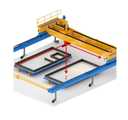
도 2는 본 발명의 일실시례에 따른 3차원 회전 갠트리 정밀위치 제어 시스템의 개념도이다.
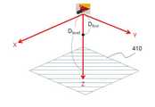
도 3은 본 발명의 일실시례에 따라 픽업부의 이동방향과 거리를 산출하기 위한 공간 상의 좌표를 나타낸 도면이다.
도 4는 본 발명의 일실시례에 따라 픽업부의 이동방향과 거리를 산출하기 위한 좌표상의 거리값을 설명하기 위한 도면이다.1 is a view showing a block diagram of a three-dimensional rotary gantry precise positioning control system according to an embodiment of the present invention.
Figure 2 is a conceptual diagram of a three-dimensional rotary gantry precise positioning control system according to an embodiment of the present invention.
3 is a view showing coordinates in space for calculating the moving direction and distance of the pickup unit according to an embodiment of the present invention.
4 is a view for explaining a distance value on coordinates for calculating the moving direction and distance of the pickup unit according to an embodiment of the present invention.
이상과 같은 본 발명에 대한 해결하고자 하는 과제, 과제의 해결 수단, 발명의 효과를 포함한 구체적인 사항들은 다음에 기재할 실시례 및 도면들에 포함되어 있다. 본 발명의 이점 및 특징, 그리고 그것들을 달성하는 방법은 첨부되는 도면과 함께 상세하게 후술되어 있는 실시례들을 참조하면 명확해질 것이다.Specific details including the problems to be solved, the means for solving the problems, and the effects of the invention for the present invention as described above are included in the examples and drawings to be described below. Advantages and features of the present invention, and a method of achieving them, will become apparent with reference to the embodiments described below in detail in conjunction with the accompanying drawings.
본 발명의 권리범위는 이하에서 설명하는 실시례에 한정되는 것은 아니며, 본 발명의 기술적 요지를 벗어나지 않는 범위 내에서 당해 기술분야의 통상적인 지식을 가진 자에 의하여 다양하게 변형 실시될 수 있다.The scope of the present invention is not limited to the embodiments described below, and various modifications may be made by those of ordinary skill in the art without departing from the technical gist of the present invention.
이하, 본 발명인 3차원 회전 갠트리 정밀위치 제어 시스템 및 그 방법은 첨부된 도 1 내지 도 4를 참고로 상세하게 설명한다.Hereinafter, the three-dimensional rotary gantry precise positioning control system and method of the present invention will be described in detail with reference to the accompanying FIGS.
도 1은 본 발명의 일실시례에 따른 3차원 회전 갠트리 정밀위치 제어 시스템의 블록도를 도시한 도면이고, 도 2는 본 발명의 일실시례에 따른 3차원 회전 갠트리 정밀위치 제어 시스템의 개념도이며, 도 3은 본 발명의 일실시례에 따라 픽업부의 이동방향과 거리를 산출하기 위한 공간 상의 좌표를 나타낸 도면이고, 도 4는 본 발명의 일실시례에 따라 픽업부의 이동방향과 거리를 산출하기 위한 좌표상의 거리값을 설명하기 위한 도면이다.1 is a view showing a block diagram of a three-dimensional rotary gantry precise positioning control system according to an embodiment of the present invention, Figure 2 is a conceptual diagram of a three-dimensional rotary gantry precise positioning control system according to an embodiment of the present invention , FIG. 3 is a view showing coordinates in space for calculating the moving direction and distance of the pickup unit according to an embodiment of the present invention, and FIG. 4 is a diagram showing the moving direction and distance of the pickup unit according to an embodiment of the present invention. It is a diagram for explaining a distance value on coordinates for
도 1을 참고하면, 본 발명의 일실시례에 따른 3차원 회전 갠트리 정밀위치 제어 시스템(100)은 x축레일부(110), y축레일부(120), 픽업부(130), z축레일부(140), 모터부(150), 데이터수신부(160), 이동제어부(170)를 포함할 수 있다.1, the three-dimensional rotary gantry precision
상기 x축레일부(110)는, 갠트리(Gantry)가 x축 방향으로 이동하도록 레일이 마련되어 상기 갠트리가 x축 이동할 수 있는 경로를 제공할 수 있다.The
이때, 상기 x축레일부(110)의 높이는 상기 갠트리의 이송 물체 또는 유체 공급 높이에 맞게 설계하여 마련될 수 있다.In this case, the height of the
상기 y축레일부(120)는, 상기 갠트리(Gantry)가 y축 방향으로 이동하도록 레일이 마련되어 상기 갠트리가 y축 이동할 수 있는 경로를 제공할 수 있다.The y-
상기 픽업부(130)는, 상기 y축레일부에 부착되어 슬라이딩하며 이송물 또는 유체 공급 호스를 파지할 수 있다.The pick-
이때, 상기 유체 공급 호스는, 상기 유량제어부(미도시)의 신호에 대응하여 유량 공급 유무 및 유량 공급량을 조절할 수 있다.In this case, the fluid supply hose may control whether or not the flow rate is supplied and the flow rate supply amount in response to a signal from the flow control unit (not shown).
상기 z축레일부(140)는, 상기 픽업부가 z축 방향으로 이동하도록 레일이 마련되어, 상기 갠트리가 z축 이동할 수 있는 경로를 제공할 수 있다.The z-
여기서, 상기 z축 높이는 상기 갠트리의 이송 물체 크기 또는 유체 공급 높이에 따라 설정되어 마련될 수 있다.Here, the z-axis height may be set and provided according to the size of the transport object of the gantry or the fluid supply height.
상기 모터부(150)는, 상기 x축레일부(110), 상기 y축레일부(120) 및 상기 z축레일부(140)에 마련되어 상기 갠트리를 이동을 전기에너지를 이용하여 동작시킬 수 있다.The
여기서, 상기 모터부(150) 내 모터는 서보모터를 이용하고, 상기 서보모터를 통해 이동된 거리는 상기 이동제어부(170)에 전송되어, 상기 이동제어부(170)가 갠트리의 현재 위치를 파악하도록 관리될 수 있다.Here, the motor in the
상기 데이터수신부(160)는, 상기 픽업부의 작업위치 및 유체공급유량을 포함하는 작업데이터를 수신할 수 있다.The
여기서, 상기 데이터수신부(160)는 외부 단말로부터 픽업부의 작업위치 및 유체공급유량 데이터를 수신하거나, 픽업부 등에 마련된 센서를 통해 필요 데이터를 수신할 수도 있다.Here, the
상기 센서는 3축 위치 센서, 거리감지 센서, 유량 감지센서를 포함할 수 있으며, 상기 3축 위치 센서 및 거리감지 센서는 상기 픽업부(130)에 마련될 수 있다.The sensor may include a three-axis position sensor, a distance sensor, and a flow rate sensor, and the three-axis position sensor and the distance sensor may be provided in the
또한, 상기 유량감지 센서는, 상기 픽업부(130)에 유량 공급호스가 체결되는 경우, 상기 유량 공급호스에 마련되어 유량 공급호스로부터 공급되는 유체의 유량을 감지할 수 있다.In addition, when the flow rate supply hose is coupled to the
상기 이동제어부(170)는, 상기 수신된 작업위치와 상기 갠트리의 현재 위치를 비교하여 상기 픽업부의 이동방향과 거리를 제어할 수 있다.The
여기서, 상기 이동제어부(170)는 상기 작업데이터 및 상기 모터부(150)에서 수신한 서보모터 이동 데이터 등을 취합하여 상기 갠트리의 위치를 산출하고, 이를 수신된 작업위치와 비교하여 상기 픽업부의 이동방향과 거리를 제어할 수 있다.Here, the
이때, 상기 갠트리의 위치는 기설정된 스마트기기 및 모니터링이 가능한 모니터링 시설에 표시될 수 있다.In this case, the location of the gantry may be displayed on a preset smart device and a monitoring facility capable of monitoring.
여기서, 상기 기설정된 스마트기기는 무선통신이 가능한 스마트폰, 태블릿pc, 노트북 등을 의미할 수 있다.Here, the preset smart device may mean a smart phone, tablet pc, notebook, etc. capable of wireless communication.
상기와 같은 작업을 수행하기 위해, 상기 3차원 회전 갠트리 정밀위치 제어 시스템은 x축레일부, y축레일부 및 z축레일부를 마련하고 픽업부에 이송물을 이송하는 경우 이송물 전용 픽업대를 장착할 수 있고, 콘크리트 등의 유체를 공급하는 경우에는, 유체 공급 호스를 체결하는 픽업부를 마련할 수 있다.In order to perform the above operation, the three-dimensional rotary gantry precise positioning control system provides an x-axis rail part, a y-axis rail part, and a z-axis rail part, and when transporting the transported material to the pickup unit, a pickup for transported material is mounted. In the case of supplying a fluid such as concrete, a pickup unit for fastening the fluid supply hose may be provided.
보다 상세하게는 상기 픽업부는, z축 방향 거리 측정을 위한 레이저 거리센서를 포함하고, 상기 이동제어부는, 상기 수신된 작업위치 내의 x좌표 및 y좌표를 이용하여 상기 픽업부의 x축 레일부 및 y축레일부의 이동을 결정하며, 상기 수신된 작업위치 내의 z좌표와 상기 레이저 거리센서를 통해 산출한 거리정보를 이용하여 상기 픽업부의 z좌표 이동거리를 최종결정하여 상기 픽업부의 이동을 제어할 수 있다.In more detail, the pickup unit includes a laser distance sensor for measuring the distance in the z-axis direction, and the movement control unit uses the x-coordinate and y-coordinate within the received work position to determine the x-axis rail and y The movement of the shaft rail part is determined, and the z coordinate movement distance of the pickup part is finally determined using the z coordinate in the received work position and the distance information calculated through the laser distance sensor to control the movement of the pickup part. .
보다 상세하게는, 픽업부가 3축 이동을 통하여 원하는 지점에 이동한 후 상기 픽업부가 파지한 이송물 또는 유체공급호스 등을 통해 작업이 수행될 수 있는데, 픽업부의 이동은 이동제어부를 통해 이루어질 수 있다.More specifically, after the pickup unit moves to a desired point through three-axis movement, the operation may be performed through a transfer object or a fluid supply hose held by the pickup unit, and the movement of the pickup unit may be made through a movement control unit. .
이동 제어부는 데이터수신부가 수신한 작업데이터로부터 작업위치를 추출하며, 상기 추출된 작업위치에는 3축 좌표계 내에서의 이동목표지점 좌표값이 포함될 수 있다. 이때, 작업데이터에 포함된 작업위치는 외부 단말 등을 통해 산출된 결과값인데, 현장에서 센싱된 정보를 통해 판단한 이동목표지점과 불일치하는 경우가 발생할 수 있으므로, 이를 종합적으로 판단하여 이동방향과 거리를 제어할 수 있다.The movement control unit extracts a work position from the work data received by the data receiver, and the extracted work position may include a coordinate value of a moving target point within a three-axis coordinate system. At this time, the work position included in the work data is a result value calculated through an external terminal, etc. However, since there may be cases where it does not match the movement target point determined through information sensed in the field, it is determined comprehensively to determine the movement direction and distance can control
따라서, 상기 픽업부의 z좌표 이동거리(Dfinal)를 최종결정하는 과정이 이루어질 수 있으며, 이는 하기 [수학식 1]에 의해 산출될 수 있다.Accordingly, a process of finally determining the z-coordinate movement distance (Dfinal ) of the pickup unit may be made, which may be calculated by the following [Equation 1].
[수학식 1] [Equation 1]

여기서, Dfinal은 최종결정된 픽업부의 z좌표 이동거리, Dfirst는 픽업부의 현재 위치 z좌표와 작업위치 내 z좌표와의 거리, N은 유량 수위면과 픽업부의 이격필요거리(상수), Dlevel은 픽업부의 현재위치 z좌표와 유량 수위면 사이의 거리(상기 레이저 거리센서를 통해 측정됨)를 각각 의미함.Here, Dfinal is the finally determined z-coordinate movement distance of the pickup unit, Dfirst is the distance between the current position z-coordinate of the pickup unit and the z-coordinate in the working position, N is the distance required to separate the pickup unit from the flow rate level surface (constant), Dlevel denotes the distance (measured through the laser distance sensor) between the current location z-coordinate of the pickup unit and the flow level surface, respectively.
상기 [수학식 1]에 의해 픽업부의 z좌표 이동거리(Dfinal)가 산출되는 과정은 도 3 및 도 4를 참고하여 보다 상세하게 설명한다. 도 3 및 도 4에서는 거푸집 내에 콘크리트를 공급하는 과정을 수행하는 중 픽업부의 z좌표 이동거리(Dfinal)가 산출되고 보정되는 과정을 예시한다.The process of calculating the z-coordinate movement distance (Dfinal ) of the pickup unit by the [Equation 1] will be described in more detail with reference to FIGS. 3 and 4 . 3 and 4 illustrate a process in which the z-coordinate movement distance (Dfinal ) of the pickup unit is calculated and corrected during the process of supplying concrete in the formwork.
도 3에 도시된 바와 같이, 픽업부를 중심으로 마련되는 3차원 좌표계 상에서 xy평면 상의 이동이 우선적으로 이루어지면, z축 이동을 통해 콘크리트를 추가 공급할 수 있는데, 이때 z축 상에서의 콘크리트 추가 공급 지점을 보정하는 과정이 필요하다.As shown in FIG. 3 , if the movement on the xy plane is preferentially performed in the three-dimensional coordinate system provided around the pickup unit, concrete can be additionally supplied through the z-axis movement, in which case the additional concrete supply point on the z-axis is selected. A correction process is required.
일례로, 작업데이터에 포함된 작업위치의 z축 좌표값은 콘크리트가 형성하는 수위면(410)과 일정한 거리를 유지하도록 산출된 것인데, 실제 현장에서 레이저 거리센서를 통해 픽업부와 콘크리트 수위면(410) 사이의 거리(Dlevel)를 측정한 결과는 작업위치의 z축 좌표값 산출에 사용된 정보와 상이할 수 있다.For example, the z-axis coordinate value of the work location included in the work data is calculated to maintain a constant distance from the
따라서, z축 좌표값 산출시에 예상했던 콘크리트 수위면(410)보다 레이저 거리센서를 통해 센싱한 수위면이 더 낮은 위치에 있는 경우, 상기 작업위치의 z축 좌표값보다 더 낮은 위치로 픽업부가 이동되어야 하고, 레이저 거리센서를 통해 센싱한 수위면이 더 높은 위치에 있는 경우, 상기 작업위치의 z축 좌표값보다 더 높은 위치로 픽업부가 이동되어야 이동 후의 픽업부와 수위면 사이의 거리(N : 기설정된 값으로 상수값)가 일정하게 유지될 수 있다.Therefore, when the water level sensed by the laser distance sensor is at a lower position than the concrete
따라서, 레이저 거리센서를 통해 픽업부와 콘크리트 수위면(410) 사이의 거리(Dlevel)와 작업위치의 z축 좌표값에 대응하여 예상된 이동예정거리(Dfirst)의 차이값을 계산하고, 그 값이 픽업부와 수위면 사이에 유지되어야 하는 이격거리(N)와의 오차값을 계산한 후, 상기 오차값을 작업위치의 z축 좌표값에 대응하여 예상된 이동예정거리(Dfirst)에 보정하는 과정으로 최종 결정되는 픽업부의 z좌표 이동거리(Dfinal)가 산출될 수 있다.Therefore, the distance between the pickup unit and the
한편, 레이저 거리센서를 통해 측정되는 상기 픽업부의 현재위치 z좌표와 유량 수위면 사이의 거리(Dlevel)는, 정밀한 측정을 위해 아래 과정을 통해 산출될 수 있다.On the other hand, the distance (Dlevel ) between the current position z-coordinate of the pickup unit and the flow level surface measured through the laser distance sensor may be calculated through the following process for precise measurement.
상기 픽업부의 현재위치 z좌표와 유량 수위면 사이의 거리(Dlevel) 산출은 우선, 상기 레이저 거리센서를 통해 기설정된 제1 횟수 측정한 값들의 제1 평균값 및 제1 표준편차를 산출하고, 상기 레이저 거리센서를 통해 기설정된 제2 횟수 측정한 값들의 제2 평균값 을 산출하여 상기 제1 평균값과 제2 평균값의 최종 평균값(Afinal)을 Dlevel으로 결정할 수 있다.The calculation of the distance (Dlevel ) between the current position z-coordinate of the pickup unit and the flow level surface is first calculated by calculating the first average value and the first standard deviation of the values measured a predetermined number of times through the laser distance sensor, and the A final average value (Afinal) of the first average value and the second average value may be determined as the Dlevel by calculating a second average value of values measured a preset second number of times through the laser distance sensor.
일례로, 1차 측정을 통해 5차례에 걸쳐 거리를 측정하고, 이들의 평균값(제1평균값)과 표준편차를 산출한 후, 2차 측정을 통해 10차례에 걸쳐 거리를 측정하고 2차 측정값들의 평균값(제2 평균값)을 산출한 후 제1 평균값과 제2 평균값의 평균을 산최종 평균값으로 산출하여 그 값을 픽업부의 현재위치 z좌표와 유량 수위면 사이의 거리(Dlevel)로 결정할 수 있다.For example, the distance is measured five times through the primary measurement, the average value (first average value) and standard deviation thereof are calculated, and then the distance is measured 10 times through the secondary measurement and the secondary measurement value After calculating the average value (second average value), the average of the first average value and the second average value is calculated as the mountain final average value, and the value can be determined as the distance (Dlevel ) between the current location z-coordinate of the pickup unit and the flow level surface. there is.
이때, 제2 평균값의 산출 과정에서 10차례에 걸쳐 측정된 거리값 중 노이즈가 존재하는 경우에는 상기 노이즈를 제거한 나머지를 이용하여 제2 평균값을 산출할 수 있다.In this case, when noise exists among the distance values measured ten times in the process of calculating the second average value, the second average value may be calculated using the remainder after the noise has been removed.
즉, 상기 제2 평균값의 산출은, 상기 제2 횟수 측정한 값들 중 노이즈를 제거한 후 평균값을 산출하되, 상기 제2 횟수 측정한 값들과 제1 평균값의 편차가 제1 표준편차의 3배수를 초과하는 값은 노이즈로 결정할 수 있다.That is, in the calculation of the second average value, the average value is calculated after removing noise among the values measured the second number of times, but the deviation between the values measured the second number of times and the first average value exceeds three times the first standard deviation The value can be determined by noise.
따라서, 제1 측정을 통해 측정된 거리값을 이용하여 제1 표준편차가 산출되면, 2차 측정을 통해 측정된 거리값 중 제1 평균값과의 편차가 표준편차의 3배를 초과할 정도라면 노이즈일 것으로 판단하여 이를 제외하고 제2 평균값을 산출함으로써, 거리 측정의 정확도를 보다 향상시킬 수 있다.Therefore, when the first standard deviation is calculated using the distance value measured through the first measurement, noise is generated if the deviation from the first average value among the distance values measured through the second measurement exceeds three times the standard deviation. By calculating the second average value by excluding this by determining that the distance is equal, the accuracy of distance measurement can be further improved.
상기와 같이, 본 발명의 일실시례에 따르면, 각 레일부의 모터부에 마련된 서보모터 및 위치 센서로부터 위치를 산출하여 상기 3차원 회전 갠트리의 정밀 위치를 산출하여 정밀 작업을 수행 할 수 있다.As described above, according to an embodiment of the present invention, it is possible to calculate the precise position of the three-dimensional rotating gantry by calculating the position from the servo motor and the position sensor provided in the motor unit of each rail unit to perform a precise operation.
또한, 픽업부를 이동시키기 위해 산출된 예상 이동거리와 현장에서의 센서에 의해 측정된 거리를 모두 반영하여 보정값을 산출함으로써 현장 상황에 맞는 최적의 이동이 이루어질 수 있다.In addition, by calculating a correction value by reflecting both the estimated movement distance calculated to move the pickup unit and the distance measured by a sensor in the field, optimal movement can be made according to the field situation.
본 발명의 일실시례에 따르면, 3차원으로 회전하는 갠트리를 정밀 제어함으로써, 이송물의 위치를 정밀하게 설정하여 이송시킬 수 있다.According to an embodiment of the present invention, by precisely controlling the gantry rotating in three dimensions, the position of the object to be transferred can be precisely set and transferred.
또한, 갠트리에 자동 유량 제어 밸브를 마련함으로써, 콘크리트와 같은 유체를 정밀하게 타설할 수 있다.In addition, by providing an automatic flow control valve on the gantry, it is possible to precisely pour a fluid such as concrete.
이상과 같이 본 발명의 일실시례는 비록 한정된 실시례와 도면에 의해 설명되었으나, 본 발명의 일실시례는 상기 설명된 실시례에 한정되는 것은 아니며, 이는 본 발명이 속하는 분야에서 통상의 지식을 가진 자라면 이러한 기재로부터 다양한 수정 및 변형이 가능하다. 따라서 본 발명의 일실시례는 아래에 기재된 특허청구범위에 의해서만 파악되어야 하고, 이의 균등 또는 등가적 변형 모두는 본 발명 사상의 범주에 속한다고 할 것이다.As described above, although one embodiment of the present invention has been described with reference to limited examples and drawings, one embodiment of the present invention is not limited to the above-described embodiment, which is common knowledge in the field to which the present invention pertains. Various modifications and variations are possible from such a base material. Accordingly, one embodiment of the present invention should be understood only by the claims described below, and all equivalents or equivalent modifications thereof will fall within the scope of the spirit of the present invention.
100 : 3차원 회전 갠트리 정밀위치 제어 시스템
110 : x축레일부
120 : y축레일부
130 : 픽업부
140 : z축레일부
150 : 모터부
160 : 데이터수신부
170 : 이동제어부100: 3D rotary gantry precision positioning system
110: x-axis rail part
120: y-axis rail part
130: pickup unit
140: z-axis rail part
150: motor unit
160: data receiving unit
170: movement control unit
Claims (5)
Translated fromKorean상기 갠트리(Gantry)가 y축 방향으로 이동하도록 레일이 마련되는 y축레일부;
상기 y축레일부에 부착되어 슬라이딩하며 이송물 또는 유체 공급 호스를 파지하는 픽업부;
상기 픽업부가 z축 방향으로 이동하도록 레일이 마련되는 z축레일부;
상기 x축레일부, 상기 y축레일부 및 상기 z축레일부에 마련되어 상기 갠트리의 이동을 전기에너지를 이용하여 동작시키는 모터부;
상기 픽업부의 작업위치 및 유체공급유량을 포함하는 작업데이터를 수신하는 데이터수신부; 및
상기 수신된 작업위치와 상기 갠트리의 현재 위치를 비교하여 상기 픽업부의 이동방향과 거리를 제어하는 이동제어부
를 포함하는 것을 특징으로 하는 3차원 회전 갠트리 정밀위치 제어 시스템.an x-axis rail portion in which a rail is provided so that the gantry moves in the x-axis direction;
a y-axis rail part provided with a rail so that the gantry moves in the y-axis direction;
a pick-up unit attached to the y-axis rail and sliding to grip the conveyed material or the fluid supply hose;
a z-axis rail part on which a rail is provided so that the pickup part moves in the z-axis direction;
a motor part provided in the x-axis rail part, the y-axis rail part, and the z-axis rail part to operate the movement of the gantry using electric energy;
a data receiving unit for receiving work data including a work position and a fluid supply flow rate of the pickup unit; and
A movement control unit for controlling the moving direction and distance of the pickup unit by comparing the received working position with the current position of the gantry
A three-dimensional rotary gantry precision positioning system comprising a.
상기 픽업부는,
z축 방향 거리 측정을 위한 레이저 거리센서를 포함하고,
상기 이동제어부는,
상기 수신된 작업위치 내의 x좌표 및 y좌표를 이용하여 상기 픽업부의 x축 레일부 및 y축레일부의 이동을 결정하고,
상기 수신된 작업위치 내의 z좌표와 상기 레이저 거리센서를 통해 산출한 거리정보를 이용하여 상기 픽업부의 z좌표 이동거리를 최종결정하여 상기 픽업부의 이동을 제어하는 것을 특징으로 하는 3차원 회전 갠트리 정밀위치 제어 시스템.The method of claim 1,
The pickup unit,
Including a laser distance sensor for measuring the distance in the z-axis direction,
The movement control unit,
Determine the movement of the x-axis rail part and the y-axis rail part of the pickup unit by using the x-coordinate and y-coordinate in the received working position,
3D rotation gantry precision position, characterized in that the z-coordinate movement distance of the pickup unit is finally determined using the z-coordinate in the received work position and the distance information calculated through the laser distance sensor to control the movement of the pickup unit control system.
상기 최종결정된 픽업부의 z좌표 이동거리(Dfinal)는,
하기 [수학식 1]에 의해 산출되는 것을 특징으로 하는 3차원 회전 갠트리 정밀위치 제어 시스템.
[수학식 1]

여기서, Dfinal은 최종결정된 픽업부의 z좌표 이동거리, Dfirst는 픽업부의 현재 위치 z좌표와 작업위치 내 z좌표와의 거리, N은 유량 수위면과 픽업부의 이격필요거리(상수), Dlevel은 픽업부의 현재위치 z좌표와 유량 수위면 사이의 거리(상기 레이저 거리센서를 통해 측정됨)를 각각 의미함.3. The method of claim 2,
The finally determined z-coordinate movement distance of the pickup unit (Dfinal ) is,
A three-dimensional rotary gantry precision position control system, characterized in that calculated by the following [Equation 1].
[Equation 1]
Here, Dfinal is the finally determined z-coordinate movement distance of the pickup unit, Dfirst is the distance between the current position z-coordinate of the pickup unit and the z-coordinate in the working position, N is the distance required to separate the pickup unit from the flow rate level surface (constant), Dlevel denotes the distance (measured through the laser distance sensor) between the current position z-coordinate of the pickup unit and the flow level surface, respectively.
상기 픽업부의 현재위치 z좌표와 유량 수위면 사이의 거리(Dlevel)는,
상기 레이저 거리센서를 통해 기설정된 제1 횟수 측정한 값들의 제1 평균값 및 제1 표준편차를 산출하고,
상기 레이저 거리센서를 통해 기설정된 제2 횟수 측정한 값들의 제2 평균값 을 산출하여 상기 제1 평균값과 제2 평균값의 최종 평균값(Afinal)을 Dlevel으로 결정하는 것을 특징으로 하는 3차원 회전 갠트리 정밀위치 제어 시스템.4. The method of claim 3,
The distance (Dlevel ) between the current position z-coordinate of the pickup unit and the flow level surface is,
Calculating a first average value and a first standard deviation of values measured a predetermined first number of times through the laser distance sensor,
A three-dimensional rotation gantry, characterized in that by calculating a second average value of values measured a predetermined second number of times through the laser distance sensor, and determining the final average value (Afinal) of the first average value and the second average value as Dlevel Precision positioning control system.
상기 제2 평균값의 산출은,
상기 제2 횟수 측정한 값들 중 노이즈를 제거한 후 평균값을 산출하되,
상기 제2 횟수 측정한 값들과 제1 평균값의 편차가 제1 표준편차의 3배수를 초과하는 값은 노이즈로 결정하는 것을 특징으로 하는 3차원 회전 갠트리 정밀위치 제어 시스템.5. The method of claim 4,
Calculation of the second average value is
After removing noise among the values measured the second number of times, an average value is calculated,
A three-dimensional rotary gantry precision positioning control system, characterized in that a value in which the deviation between the values measured the second number of times and the first average value exceeds three times the first standard deviation is determined as noise.
Priority Applications (1)
| Application Number | Priority Date | Filing Date | Title |
|---|---|---|---|
| KR1020210187154AKR102362476B1 (en) | 2021-12-24 | 2021-12-24 | 3d rotary gantry precision positioning system and method therefor |
Applications Claiming Priority (1)
| Application Number | Priority Date | Filing Date | Title |
|---|---|---|---|
| KR1020210187154AKR102362476B1 (en) | 2021-12-24 | 2021-12-24 | 3d rotary gantry precision positioning system and method therefor |
Publications (2)
| Publication Number | Publication Date |
|---|---|
| KR102362476B1true KR102362476B1 (en) | 2022-02-16 |
| KR102362476B9 KR102362476B9 (en) | 2022-10-21 |
Family
ID=80474937
Family Applications (1)
| Application Number | Title | Priority Date | Filing Date |
|---|---|---|---|
| KR1020210187154AActiveKR102362476B1 (en) | 2021-12-24 | 2021-12-24 | 3d rotary gantry precision positioning system and method therefor |
Country Status (1)
| Country | Link |
|---|---|
| KR (1) | KR102362476B1 (en) |
Citations (1)
| Publication number | Priority date | Publication date | Assignee | Title |
|---|---|---|---|---|
| KR20110012092A (en)* | 2009-07-29 | 2011-02-09 | 창원대학교 산학협력단 | 3-axis robot and gantry type machining system |
- 2021
- 2021-12-24KRKR1020210187154Apatent/KR102362476B1/enactiveActive
Patent Citations (2)
| Publication number | Priority date | Publication date | Assignee | Title |
|---|---|---|---|---|
| KR20110012092A (en)* | 2009-07-29 | 2011-02-09 | 창원대학교 산학협력단 | 3-axis robot and gantry type machining system |
| KR101095690B1 (en) | 2009-07-29 | 2011-12-20 | 창원대학교 산학협력단 | 3-axis robot and gantry type machining system |
Also Published As
| Publication number | Publication date |
|---|---|
| KR102362476B9 (en) | 2022-10-21 |
Similar Documents
| Publication | Publication Date | Title |
|---|---|---|
| CN110621447B (en) | Robot conveyor calibration method, robot system and control system | |
| US10876307B2 (en) | Construction management system and method | |
| US20110087360A1 (en) | Robot parts assembly on a workpiece moving on an assembly line | |
| JP2013063474A (en) | Robot system and imaging method | |
| CN107044837B (en) | For demarcating the method, apparatus and control equipment of detection instrument coordinate system | |
| EP3260245B1 (en) | Bending robot and workpiece detection method | |
| CN102269994A (en) | Automatic guided vehicle and method for drive control of same | |
| US20150066195A1 (en) | Method for positioning a tool of a machine tool in the visual field of a visual system and relative machine tool | |
| CN109983299A (en) | The measuring system and method for industrial robot | |
| CN107830832A (en) | Workpiece profile scanning system and method | |
| CN103900510A (en) | Detection path modeling method of coordinate measuring machine | |
| US20210174555A1 (en) | Display device and display program | |
| CN109839075A (en) | A kind of robot automatic measurement system and measurement method | |
| US20220203549A1 (en) | Suction pad and deformation measuring device | |
| KR102362476B1 (en) | 3d rotary gantry precision positioning system and method therefor | |
| US20230364812A1 (en) | Robot system | |
| JPWO2020032157A1 (en) | Article position estimation system and article position estimation method | |
| CN114436172A (en) | Lifting mechanism, robot and method for processing materials | |
| US20170131702A1 (en) | Automatic position adjustment system | |
| TWI447549B (en) | Method for determining the arrival position of moving body system and moving body | |
| CN115771138A (en) | Method and system for positioning a mobile robotic system | |
| US20150300842A1 (en) | Device and Method For Determining the Change of Position of a 3D Measuring Head | |
| JP2012016769A (en) | Mount device and method of visual sensor | |
| WO2021010109A1 (en) | Work machine | |
| US20180311823A1 (en) | Method for orienting an effector carrying an assembly tool relative to a surface |
Legal Events
| Date | Code | Title | Description |
|---|---|---|---|
| A302 | Request for accelerated examination | ||
| PA0109 | Patent application | Patent event code:PA01091R01D Comment text:Patent Application Patent event date:20211224 | |
| PA0201 | Request for examination | ||
| PA0302 | Request for accelerated examination | Patent event date:20211224 Patent event code:PA03022R01D Comment text:Request for Accelerated Examination | |
| E701 | Decision to grant or registration of patent right | ||
| PE0701 | Decision of registration | Patent event code:PE07011S01D Comment text:Decision to Grant Registration Patent event date:20220124 | |
| GRNT | Written decision to grant | ||
| PR0701 | Registration of establishment | Comment text:Registration of Establishment Patent event date:20220209 Patent event code:PR07011E01D | |
| PR1002 | Payment of registration fee | Payment date:20220209 End annual number:3 Start annual number:1 | |
| PG1601 | Publication of registration | ||
| G170 | Re-publication after modification of scope of protection [patent] | ||
| PG1701 | Publication of correction | Patent event code:PG17011E01I Patent event date:20221018 Comment text:Request for Publication of Correction Publication date:20221021 | |
| PR1001 | Payment of annual fee | Payment date:20250123 Start annual number:4 End annual number:4 |