KR102360346B1 - Medical Needle Apparatus - Google Patents
Medical Needle ApparatusDownload PDFInfo
- Publication number
- KR102360346B1 KR102360346B1KR1020190179618AKR20190179618AKR102360346B1KR 102360346 B1KR102360346 B1KR 102360346B1KR 1020190179618 AKR1020190179618 AKR 1020190179618AKR 20190179618 AKR20190179618 AKR 20190179618AKR 102360346 B1KR102360346 B1KR 102360346B1
- Authority
- KR
- South Korea
- Prior art keywords
- locking knob
- needle
- handle
- exterior
- fixing part
- Prior art date
- Legal status (The legal status is an assumption and is not a legal conclusion. Google has not performed a legal analysis and makes no representation as to the accuracy of the status listed.)
- Active
Links
Images


Classifications
- A—HUMAN NECESSITIES
- A61—MEDICAL OR VETERINARY SCIENCE; HYGIENE
- A61B—DIAGNOSIS; SURGERY; IDENTIFICATION
- A61B17/00—Surgical instruments, devices or methods
- A61B17/34—Trocars; Puncturing needles
- A61B17/3417—Details of tips or shafts, e.g. grooves, expandable, bendable; Multiple coaxial sliding cannulas, e.g. for dilating
- A61B17/3421—Cannulas
- A—HUMAN NECESSITIES
- A61—MEDICAL OR VETERINARY SCIENCE; HYGIENE
- A61B—DIAGNOSIS; SURGERY; IDENTIFICATION
- A61B10/00—Instruments for taking body samples for diagnostic purposes; Other methods or instruments for diagnosis, e.g. for vaccination diagnosis, sex determination or ovulation-period determination; Throat striking implements
- A61B10/02—Instruments for taking cell samples or for biopsy
- A61B10/0233—Pointed or sharp biopsy instruments
- A—HUMAN NECESSITIES
- A61—MEDICAL OR VETERINARY SCIENCE; HYGIENE
- A61B—DIAGNOSIS; SURGERY; IDENTIFICATION
- A61B10/00—Instruments for taking body samples for diagnostic purposes; Other methods or instruments for diagnosis, e.g. for vaccination diagnosis, sex determination or ovulation-period determination; Throat striking implements
- A61B10/02—Instruments for taking cell samples or for biopsy
- A61B10/04—Endoscopic instruments, e.g. catheter-type instruments
- A—HUMAN NECESSITIES
- A61—MEDICAL OR VETERINARY SCIENCE; HYGIENE
- A61B—DIAGNOSIS; SURGERY; IDENTIFICATION
- A61B17/00—Surgical instruments, devices or methods
- A61B17/34—Trocars; Puncturing needles
- A61B17/3403—Needle locating or guiding means
- A—HUMAN NECESSITIES
- A61—MEDICAL OR VETERINARY SCIENCE; HYGIENE
- A61B—DIAGNOSIS; SURGERY; IDENTIFICATION
- A61B17/00—Surgical instruments, devices or methods
- A61B17/34—Trocars; Puncturing needles
- A61B17/3472—Trocars; Puncturing needles for bones, e.g. intraosseus injections
- A—HUMAN NECESSITIES
- A61—MEDICAL OR VETERINARY SCIENCE; HYGIENE
- A61B—DIAGNOSIS; SURGERY; IDENTIFICATION
- A61B10/00—Instruments for taking body samples for diagnostic purposes; Other methods or instruments for diagnosis, e.g. for vaccination diagnosis, sex determination or ovulation-period determination; Throat striking implements
- A61B10/02—Instruments for taking cell samples or for biopsy
- A61B10/04—Endoscopic instruments, e.g. catheter-type instruments
- A61B2010/045—Needles
- A—HUMAN NECESSITIES
- A61—MEDICAL OR VETERINARY SCIENCE; HYGIENE
- A61B—DIAGNOSIS; SURGERY; IDENTIFICATION
- A61B17/00—Surgical instruments, devices or methods
- A61B2017/0042—Surgical instruments, devices or methods with special provisions for gripping
- A61B2017/00455—Orientation indicators, e.g. recess on the handle
- A—HUMAN NECESSITIES
- A61—MEDICAL OR VETERINARY SCIENCE; HYGIENE
- A61B—DIAGNOSIS; SURGERY; IDENTIFICATION
- A61B17/00—Surgical instruments, devices or methods
- A61B2017/0046—Surgical instruments, devices or methods with a releasable handle; with handle and operating part separable
- A—HUMAN NECESSITIES
- A61—MEDICAL OR VETERINARY SCIENCE; HYGIENE
- A61B—DIAGNOSIS; SURGERY; IDENTIFICATION
- A61B17/00—Surgical instruments, devices or methods
- A61B17/34—Trocars; Puncturing needles
- A61B17/3403—Needle locating or guiding means
- A61B2017/3405—Needle locating or guiding means using mechanical guide means
- A61B2017/3409—Needle locating or guiding means using mechanical guide means including needle or instrument drives
- A—HUMAN NECESSITIES
- A61—MEDICAL OR VETERINARY SCIENCE; HYGIENE
- A61B—DIAGNOSIS; SURGERY; IDENTIFICATION
- A61B17/00—Surgical instruments, devices or methods
- A61B17/34—Trocars; Puncturing needles
- A61B2017/347—Locking means, e.g. for locking instrument in cannula
Landscapes
- Health & Medical Sciences (AREA)
- Life Sciences & Earth Sciences (AREA)
- Surgery (AREA)
- Heart & Thoracic Surgery (AREA)
- Molecular Biology (AREA)
- Pathology (AREA)
- Engineering & Computer Science (AREA)
- Biomedical Technology (AREA)
- Veterinary Medicine (AREA)
- Medical Informatics (AREA)
- Public Health (AREA)
- Animal Behavior & Ethology (AREA)
- General Health & Medical Sciences (AREA)
- Nuclear Medicine, Radiotherapy & Molecular Imaging (AREA)
- Orthopedic Medicine & Surgery (AREA)
- Radiology & Medical Imaging (AREA)
- Infusion, Injection, And Reservoir Apparatuses (AREA)
Abstract
Translated fromKoreanDescription
Translated fromKorean본 발명은 의료용 니들장치에 관한 것으로, 더욱 상세하게는 환자의 환부에 미세한 통로를 만들어 주거나, 체내조직 일부를 채취할 수 있는 의료용 니들장치에 관한 것이다.The present invention relates to a medical needle device, and more particularly, to a medical needle device capable of making a fine passage in an affected part of a patient or collecting a part of body tissue.
일반적으로 인체의 내부로 특정 물질을 주입하거나, 인체의 특정 부분의 조직을 획득하기 위하여 다양한 종류의 수술 도구들이 사용된다. 이러한 수술 도구들은 일반적으로 인체 내부로의 접근이 용이하여야 하고 시술자의 시술편의 및 수술시 피수술자의 안전성을 보장하여야 한다.In general, various types of surgical tools are used to inject a specific substance into a human body or to obtain a tissue of a specific part of the human body. In general, these surgical tools should be easy to access to the inside of the human body, and should ensure the operator's convenience and safety of the operator during surgery.
이러한 수술 도구는 목적이나 수술 부위에 따라 다양한 형태와 종류를 이루게 되는데, 예를 들어, 밀도가 높고 단단한 뼈와 같은 조직이나 척추와 같이 신경이 집중되어 고도의 정밀함을 요하는 부분에는 이에 맞는 특수한 수술 도구가 사용되어야 한다.These surgical tools come in various shapes and types depending on the purpose or the surgical site. For example, special surgery suitable for dense and hard tissues such as bones or areas requiring high precision due to the concentration of nerves such as the spine. tools should be used.
또한, 니들을 삽입하면서 정확한 위치로 삽입이 이루어지고 있는지 확인을 하기 위하여 수술 중 다수회의 엑스선 촬영을 하게 되는데, 엑스선 촬영 및 판독 과정에서 니들의 손잡이에 의해 가려지는 부위가 적지않게 발생하게 되므로 정확한 엑스선 촬영이 이루어지지 않게 된다. 따라서 엑스선촬영 이미지를 통한 정확한 확인 및 판단이 어렵게 되어 니들 삽입의 정확성을 확보하기가 상당히 어렵게 되는 문제점이 있다. 따라서, 이러한 불편함을 해결할 수 있는 기술이 요구된다.In addition, while inserting the needle, X-rays are taken multiple times during the operation to check whether the insertion is being made in the correct position. Shooting will not take place. Therefore, there is a problem in that it is difficult to accurately confirm and determine through the X-ray image, so that it is quite difficult to secure the accuracy of needle insertion. Accordingly, there is a need for a technology capable of solving such inconveniences.
상술한 문제점을 해결하기 위해 안출된 본 발명의 목적은, 환자의 환부에 미세한 통로를 만들어 주거나, 체내조직 일부를 채취할 수 있는 의료용 니들장치를 제공하는 데에 있다.It is an object of the present invention devised to solve the above problems, to provide a medical needle device that can make a fine passage in the affected part of the patient, or to collect a part of the body tissue.
상술한 과제를 해결하기 위한 본 발명은, 핸들 및 상기 핸들에 회전가능하도록 고정되는 락킹노브를 가지는 핸들부 및 상기 락킹노브의 삽입홀에 적어도 일부가 삽입되는 니들어셈블리를 포함하고, 상기 락킹노브의 회전에 의해 상기 삽입홀의 단면형상과 상기 니들어셈블리의 삽입된 부분 중 최하단의 단면형상을 서로 엇갈리게 하여 상기 삽입홀 내에서 상기 니들어셈블리의 부분이 고정되는 것을 특징으로 하는 의료용 니들장치이다.The present invention for solving the above problems includes a handle part having a handle and a locking knob rotatably fixed to the handle, and a needle assembly in which at least a part is inserted into an insertion hole of the locking knob, It is a medical needle device characterized in that the cross-sectional shape of the insertion hole and the cross-sectional shape of the lowermost end of the inserted part of the needle assembly are crossed with each other by rotation, and the part of the needle assembly is fixed in the insertion hole.
또, 상기 니들어셈블리는 중공의 외관, 상기 외관의 일단에 고정되는 외관고정부, 상기 외관의 내부에 삽입되는 니들 및 상기 니들의 일단에 고정되고, 상기 외관고정부에 착탈가능한 니들고정부를 포함하고, 상기 니들고정부가 장착된 상태에서 상기 외관고정부의 적어도 일부분이 상기 삽입홀을 통해 상기 락킹노브 내에 삽입되는 것을 특징으로 한다.In addition, the needle assembly includes a hollow exterior, an exterior fixing part fixed to one end of the exterior, a needle inserted into the interior of the exterior, and a needle fixing part fixed to one end of the needle and detachable from the exterior fixing part and at least a portion of the exterior fixing part is inserted into the locking knob through the insertion hole in a state in which the needle fixing part is mounted.
또, 상기 외관고정부의 상기 외관의 반대측 단부에는 체결나사가 형성되는 것을 특징으로 한다.In addition, it is characterized in that the fastening screw is formed at the end opposite to the exterior of the exterior fixing part.
또, 상기 외관고정부의 하단에는 상기 삽입홀의 외측으로 노출되는 노출파지부를 가지는 것을 특징으로 한다.In addition, the lower end of the exterior fixing part is characterized in that it has an exposed holding part exposed to the outside of the insertion hole.
또, 상기 핸들의 상단에는 타격할 수 있는 타격자리가 형성된 것을 특징으로 한다.In addition, the upper end of the handle is characterized in that the hitting seat that can hit is formed.
또, 상기 타격자리에는 니들의 방향을 확인할 수 있는 마킹부가 형성되어 있는 것을 특징으로 한다.In addition, the hitting seat is characterized in that a marking portion that can confirm the direction of the needle is formed.
또, 상기 핸들의 내부에는 상기 락킹노브의 내부와 연통되고, 상기 니들고정부가 장착된 상태에서 상기 외관고정부의 일부분이 안착되는 핸들수용부가 형성된 것을 특징으로 한다.In addition, it is characterized in that the handle receiving portion communicating with the inside of the locking knob is formed on the inside of the handle, and in which a part of the external fixing part is seated in a state in which the needle fixing part is mounted.
또, 상기 핸들의 상기 락킹노브와 결합되는 제1결합부에는 상기 락킹노브에 형성된 이동제한부가 연결되는 제한자리부가 형성되어, 상기 핸들과 락킹노브의 상대운동의 각범위를 한정하는 것을 특징으로 한다.In addition, the first coupling portion coupled to the locking knob of the handle is formed with a limiting seat portion to which the movement limiting portion formed on the locking knob is connected to limit the angular range of relative motion between the handle and the locking knob. .
또, 상기 이동제한부는 상기 락킹노브에서 돌출된 하나 이상의 락킹돌출부이며, 상기 제한자리부는 오목하게 소정의 각으로 형성된 이동제한홈인 것을 특징으로 한다.In addition, the movement limiting part is one or more locking protrusions protruding from the locking knob, and the limiting seat part is a movement limiting groove concavely formed at a predetermined angle.
또, 상기 락킹노브에는 상기 외관고정부를 상향으로 가세하도록 가세부가 형성된 것을 특징으로 한다.In addition, the locking knob is characterized in that a biasing portion is formed to bias the exterior fixing portion upward.
또, 상기 가세부는 상기 락킹노브의 삽입홀 주위로 형성되는 테이퍼부이며, 상기 락킹노브를 회전시키면 상기 외관고정부의 저면을 상향으로 밀어부치는 것을 특징으로 한다.In addition, the biasing portion is a tapered portion formed around the insertion hole of the locking knob, characterized in that when the locking knob is rotated to push the bottom surface of the exterior fixing part upward.
또, 상기 외관고정부의 저면에는 제1고정유지부가 형성되고, 상기 락킹노브에는 상기 제1고정유지부에 대응하는 제2고정유지부가 형성되며, 상기 락킹노브를 회전시키면 상기 제1고정유지부와 상기 제2고정유지부가 서로 결합하여 상기 니들어셈블리가 상기 핸들에 대해 고정상태를 유지하는 것을 특징으로 한다.In addition, a first fixed holding part is formed on a bottom surface of the exterior fixing part, and a second fixed holding part corresponding to the first fixed holding part is formed on the locking knob, and when the locking knob is rotated, the first fixed holding part is formed. And the second fixed holding part is coupled to each other, characterized in that the needle assembly maintains a fixed state with respect to the handle.
본 발명을 통하여, 의료용 니들장치의 니들과 핸들의 분리가 가능하여 사용 시 환부의 시야를 가리지 않고 편리한 사용이 가능하다.Through the present invention, it is possible to separate the needle and handle of the medical needle device, so that it can be used conveniently without obstructing the view of the affected part.
또한, 본 발명을 통하여 핸들과 니들이 흔들림없이 결착되어 안정적인 사용이 가능하다.In addition, through the present invention, the handle and the needle are coupled without shaking, so that stable use is possible.
도 1a은 본 발명의 실시예에 따른 의료용 니들장치의 사시도이다.
도 1b는 본 발명의 실시예에 따른 의료용 니들장치의 핸들부와 니들어셈블리가 분해된 분해사시도이다.
도 2는 본 발명의 실시예에 따른 의료용 니들장치의 전체 분해사시도이다.
도 3은 본 발명의 실시예에 따른 의료용 니들장치 핸들을 하측에서 바라본 사시도이다.
도 4는 본 발명의 실시예에 따른 의료용 니들장치 핸들을 상측에서 바라본 사시도이다.
도 5는 본 발명의 실시예에 따른 의료용 니들장치의 락킹노브 내측을 나타낸 사시도이다.
도 6은 본 발명의 실시예에 따른 의료용 니들장치의 락킹노브 외측을 나타낸 사시도이다.
도 7은 본 발명의 실시예에 따른 의료용 니들장치의 락킹노브의 일부를 나타낸 전개도의 일부이다.
도 8은 본 발명의 실시예에 따른 의료용 니들장치의 락킹노브의 평면도이다.
도 9는 본 발명의 실시예에 따른 의료용 니들장치의 니들어셈블리의 전체사시도이다.
도 10은 본 발명의 실시예에 따른 의료용 니들장치의 니들어셈블리의 분해사시도이다.
도 11은 본 발명의 실시예에 따른 니들어셈블리의 외관고정부 사시도이다.
도 12는 본 발명의 실시예에 따른 니들어셈블리의 니들고정부 사시도이다.
도 13은 본 발명의 실시예에 따른 의료용 니들장치의 사용방법을 나타낸 개략도이다.Figure 1a is a perspective view of a medical needle device according to an embodiment of the present invention.
Figure 1b is an exploded perspective view in which the handle part and the needle assembly of the medical needle device according to the embodiment of the present invention are disassembled.
Figure 2 is an overall exploded perspective view of the medical needle device according to an embodiment of the present invention.
Figure 3 is a perspective view of the medical needle device handle in accordance with an embodiment of the present invention viewed from the lower side.
Figure 4 is a perspective view of the medical needle device handle in accordance with an embodiment of the present invention viewed from the upper side.
5 is a perspective view showing the inside of the locking knob of the medical needle device according to an embodiment of the present invention.
6 is a perspective view showing the outside of the locking knob of the medical needle device according to an embodiment of the present invention.
7 is a part of an exploded view showing a part of the locking knob of the medical needle device according to an embodiment of the present invention.
8 is a plan view of the locking knob of the medical needle device according to an embodiment of the present invention.
9 is an overall perspective view of the needle assembly of the medical needle device according to the embodiment of the present invention.
10 is an exploded perspective view of the needle assembly of the medical needle device according to the embodiment of the present invention.
11 is a perspective view of an exterior fixing part of a needle assembly according to an embodiment of the present invention.
12 is a perspective view of the needle fixing part of the needle assembly according to an embodiment of the present invention.
13 is a schematic diagram showing a method of using a medical needle device according to an embodiment of the present invention.
이하, 본 발명을 바람직한 실시예를 첨부한 도면을 참조하여 설명하기로 한다. 하기의 각 도면의 구성 요소들에 참조 부호를 부가함에 있어서, 동일한 구성 요소들에 한해서는 비록 다른 도면상에 표시되더라도 가능한 한 동일한 부호를 가지도록 하며, 본 발명의 요지를 불필요하게 흐릴 수 있다고 판단되는 공지 기능 및 구성에 대한 상세한 설명은 생략한다.Hereinafter, preferred embodiments of the present invention will be described with reference to the accompanying drawings. In adding reference numerals to the components of the drawings below, it is determined that the same components are given the same reference numerals as much as possible even if they are displayed on different drawings, and it is determined that the subject matter of the present invention may be unnecessarily obscured. Detailed description of known functions and configurations will be omitted.
도 1a 내지 도 2를 참조하여 본 발명에 따른 의료용 니들장치(10)를 설명한다. 도 1a 내지 도 2에 도시된 바와 같이, 상기 의료용 니들장치(10)는 크게 나누어 핸들부(11) 및 니들어셈블리(12)를 포함한다. 상기 핸들부(11)는 핸들(100) 및 상기 핸들(100)에 회전가능하도록 고정되는 락킹노브(200)를 포함하고, 상기 니들어셈블리(12)의 적어도 일부가 상기 락킹노브(200)의 삽입홀(250)에 삽입된다.A
상기 니들어셈블리(12)는 니들부(500) 및 상기 니들부(500)가 내부에 삽입되는 외관부(400)로 구성된다. 상기 니들부(500)는 니들고정부(501) 및 니들(502)로 구성되어 있으며, 상기 외관부(400)는 외관고정부(401) 및 외관(402)으로 구성되어 있다.The
본 명세서에서 상부방향은 상기 핸들(100)을 향하는 방향을 의미하며, 하부방향은 상부방향의 반대방향을 의미한다.In this specification, the upper direction refers to a direction toward the
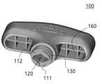
다음으로, 도 3 및 도 4를 참조하여 본 발명에 따른 의료용 니들장치(10)의 핸들부(11)를 설명한다. 도 3 및 도 4에 도시된 바와 같이, 상기 핸들(100)은 사용자의 편의를 위하여 T자 형상으로 형성되어 있다. 또한, 상기 핸들(100)의 내부는 격자구조 프레임(160)으로 구성되어 충분한 구조적 안정성을 가지면서도, 중량을 감소시킬 수 있다. 또, 제품의 제조 시 냉각시간을 줄일 수 있어 제조시간을 단축시킬 수 있는 장점이 있다.Next, the
또한, 상기 핸들(100)은 상측방향 최상측에 위치하는 두부(170)에 평면으로 이루어진 타격자리(140)를 포함하고, 상기 타격자리(140)는 그 면의 중심의 법선이 상기 니들(502)의 축선과 일치하도록 형성된다.In addition, the
그리고, 상기 핸들(100)은 상기 락킹노브(200)와 결합할 수 있는 제1결합부(130)를 포함하고, 상기 제1결합부(130)는 상기 타격자리(140)의 반대방향에 위치한다.In addition, the
상기 제1결합부(130)는 적어도 하나 이상의 고리형상 돌출부일 수 있으나, 반드시 이에 한정되지 않으며 기타 다른 형상으로 형성될 수 있다.The
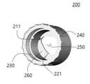
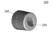
다음으로, 도 5 내지 도 8을 참조하여 본 발명에 따른 의료용 니들장치(10)의 락킹노브(200)를 설명한다. 도 5 내지 도 8에 도시된 바와 같이, 상기 락킹노브(200)는 상부는 개방되고 하부는 폐쇄되어 있으며 상기 폐쇄된 하부에는 삽입부(250)가 관통되게 형성되어 있다. 상기 락킹노브(200)는 상기 핸들(100)에 형성된 상기 제1결합부(130)와 결합된다.Next, the
또, 상기 락킹노브(200)의 일단에는 상기 핸들(100)의 제1결합부(130)와 결합하기 위한 제2결합부(230)가 형성된다. 상기 제2결합부(230)는 상기 락킹노브(200) 내부에 형성될 수 있다. 상기 제2결합부(230)는 고리형상의 돌출부를 가진 상기 제1결합부(130)가 맞물려 결합될 수 있도록 고리형상의 홈이 형성될 수 있다. 하지만, 상기 제2결합부(230)의 형상은 반드시 이에 한정되지 않으며, 상기 제1결합부(130)에는 고리형상 홈이 형성되고 상기 제2결합부(230)에는 고리형상 돌출부가 형성될 수 있다. 또, 동일한 기능을 하는 기타 다른 형상을 사용하여 상기 제1결합부(130)와 상기 제2결합부(230)가 서로 결합할 수 있다.In addition, a
상기 락킹노브(200) 외면의 일부에는 미끄럼방지부(240)가 형성되어, 사용자가 락킹노브(200)를 조작할 때 미끄러지는 것을 방지할 수 있다. 또, 상기 락킹노브(200)의 하부에는 상기 니들어셈블리(12)가 삽입되는 삽입홀(250)이 형성되며, 상기 삽입홀(250)은 세장비(slenderness ratio)가 크게 형성된 장원이거나 타원 또는 다각형으로 형성될 수 있다.A
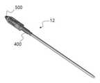
다음으로, 도 9 내지 도 13를 참조하여 본 발명에 따른 의료용 니들장치(10)의 니들어셈블리(12)를 설명한다. 도 9 내지 도 12에 도시된 바와 같이, 상기 니들어셈블리(12)는 니들부(500) 및 상기 니들부(500)가 내부에 삽입되는 외관부(400)로 구성된다.Next, the
상기 니들부(500)는 니들(502) 및 니들고정부(501)로 구성되어 있으며, 상기 외관부(400)는 외관(402) 및 외관고정부(401)로 구성되어 있다. 상기 니들부(500)는 상기 외관부(400)에 착탈가능하도록 형성되며, 상기 니들부(500)가 장착된 상태에서 상기 외관부(400)의 적어도 일부분이 상기 락킹노브(200)의 삽입홀(250)을 통해 상기 락킹노브(200) 내에 삽입되는 것을 특징으로 한다.The
도 11 및 도 12에 도시된 바와 같이, 상기 외관고정부(401)는 제1체결부(410), 몸통부(420) 및 노출파지부(430)를 포함한다. 상기 제1체결부(410)는 체결홈(412)을 포함하고, 상기 제1체결부(410) 외부 또는 내부에는 체결나사(411)가 더 형성될 수 있다. 또, 상기 제1체결홈(412)을 통하여 상기 니들부(500)와 상기 외관부(400)가 서로 결합할 수 있다. 또한, 상기 외관고정부(401)는 내부에 상기 외관고정부(401)의 길이방향으로 내부홀(441)이 형성되어 있으며, 상기 내부홀(441)의 일부에 상기 외관(402)의 일부가 삽입된다. 따라서 상기 내부홀(441)은 상기 외관(402)과 연통될 수 있다.11 and 12 , the
상기 제1체결부(410)는 상기 외관고정부(401)의 상기 외관(402)의 반대측 단부에 위치한다.The
상기 체결나사(411)는 상기 외관(402)을 통해 약물 등을 주입하기 위한 별도의 장치(미도시)를 결합하기 위하여 형성될 수 있다.The
상기 몸통부(420)는 상기 제1체결부(410) 및 상기 노출파지부(430) 사이에 위치하며, 상기 핸들부(11)로부터 상기 니들어셈블리(12)를 분리하였을 때, 사용자가 니들어셈블리(12)를 잡을 수 있는 손잡이 역할을 한다. 상기 몸통부(420)에는 사용자가 용이하게 상기 몸통부(420)를 잡을 수 있도록 제1파지홈(421)이 형성된다.The
상기 노출파지부(430)는 상기 외관고정부(401)의 하단에 위치하고 있으며, 제1파지부(431) 및 튜브커넥터(432)를 포함한다. 상기 노출파지부(430)는 상기 락킹노브(200)의 삽입홀(250) 외측으로 노출된다. 따라서, 상기 노출파지부(430)는 상기 니들어셈블리(12)가 상기 핸들부(11)와 결합했을 때, 상기 핸들부(11)의 외부로 노출되어 있어서 사용자가 손잡이로 사용할 수 있다.The exposed holding
상기 노출파지부(430) 하부에는 상기 외관(402) 및 니들(502) 보호를 위한 안전튜브(미도시)를 체결하기 위하여 튜브커넥터(432)가 형성된다. 상기 튜브커넥터(432)는 상기 안전튜브(미도시)의 삽입을 안내하기 위하여 형성되어 있으며, 상기 외관고정부(401)의 길이방향으로 돌기가 복수개 형성될 수 있다.A
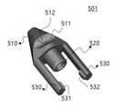
도 13에 도시된 바와 같이, 상기 니들고정부(501)는 파지부(510)와 삽입부 (520) 및 제2체결부(530)로 구성된다. 상기 파지부(510)는 상기 니들어셈블리(12)를 핸들부(11)에 삽입할 때, 상기 니들어셈블리(12)가 용이하게 상기 핸들부(11)에 삽입될 수 있도록, 뿔 형상으로 형성될 수 있다. 또, 상기 파지부(510)는 사용자가 잡기 쉽도록 제2파지홈(511)을 포함한다. 상기 삽입부(520)는 상기 파지부(510) 하측에 위치하고 있으며, 상기 외관고정부(401) 제1체결부(410)의 내부홀(441)에 삽입된다. 상기 제2체결부(530)는 상기 파지부(510) 하측방향 말단에 적어도 두개 이상 니들고정부(501)의 길이방향으로 형성되어 있으며, 상기 제2체결부(530)의 말단 내측에는 돌기(531, 532)가 형성되어 있다. 상기 돌기(531, 532)는 상기 제1체결부(410)의 제1체결홈(412)에 결합된다. 이때, 상기 돌기(531, 532) 말단은 상기 돌기(531, 532)가 상기 제1체결홈(412)에 용이하게 결합될 수 있도록 라운드 형상을 가진다.As shown in FIG. 13 , the
상기 외관고정부(401)의 제1체결부(410)가 상기 삽입부(520)에 삽입되고, 상기 제2체결부(530) 말단 내측 돌기(531)가 상기 제1체결홈(412)에 체결되면서 상기 니들부(500) 및 상기 외관부(400)가 서로 체결된다.The
상기 외관(402)은 상기 외관고정부(401)에 연결되어 있으며, 말단에 테이퍼부(403)를 포함하고 있어 니들(502)을 조직에 삽입할 때 더 용이하게 삽입할 수 있다. 또한, 상기 외관(402)에 마킹부(미도시)를 더 포함하여 사용자가 니들(502)의 삽입량을 확인할 수 있다.The exterior 402 is connected to the
상기 니들(502)은 상기 니들고정부(501)에 연결되어 있으며, 조직에 삽입하기 위하여 말단이 날카롭게 형성되어 있다. 상기 니들(502)의 말단 형상은 트로카(troca), 베밸드(beveled) 및 다이아몬드(diamond) 형상일 수 있으나, 상기 니들(502)의 형상은 상기 니들을 인체조직에 삽입할 수 있는 형태라면 특별히 한정되는 것은 아니며, 변경이 가능하다.The
상기 니들(502)의 형태가 비스듬한 형상인 베밸드(beveled) 형태일 경우에는 상기 니들(502)의 날카로운 부분이 어느 방향을 향하고 있는 지를 나타내기 위하여 상기 니들(502)의 방향을 표시하는 제1마킹부(150)를 상기 핸들(100)의 타격자리(140)에 더 포함할 수 있다. 상기 타격자리(140)에 상기 제1마킹부(150)가 위치함으로써, 사용자가 상기 핸들(100)을 타격할 때 시인성이 좋아지도록 할 수 있고, 베밸드(bevedled) 형태 니들(502)의 날카로운 부분이 어느 방향을 향하고 있는지 표시할 수 있다.When the shape of the
또, 상기 제2파지홈(511)의 일면에도 상기 니들(502)의 방향을 사용자에게 인식시키기 위한 제2마킹부(512)가 형성된다. 상기 니들(502)이 베밸드(beveled) 형상일 경우 상기 제2마킹부(512)는 상기 니들어셈블리(12)과 상기 핸들부(11)가 분리되었을 때, 상기 니들(502)의 날카로운 부분이 향하는 쪽을 사용자에게 인식시키는 역할을 할 수 있다.In addition, a
상기 니들(502)이 베밸드(beveled) 형상일 때, 상기 핸들부(11) 및 상기 니들어셈블리(12)가 결합된 상태로 제공되는 경우, 상기 제1마킹부(150) 및 상기 제2마킹부(512)는 같은 방향을 향하도록 결합되어야 한다.When the
상기 핸들(100)의 제1결합부(130)의 일단에는 적어도 하나 이상의 제한자리부가 형성되어 있다. 상기 제한자리부는 오목하게 소정의 각으로 형성된 이동제한홈(111, 112)인 것을 특징으로 한다. 상기 제1결합부(130)에서 이동제한홈(111, 112)으로 형성되어 있는 제한자리부를 제외한 나머지 부분은 돌출되어 형성될 수 있다. 하지만, 상기 제한자리부의 형상은 반드시 이에 한정되지 않고 홈이 아닌 돌출된 형상일 수 있으며, 동일한 기능을 할 수 있다면 다른 형상으로 형성될 수 있다.At least one limiting seat portion is formed at one end of the
또, 상기 핸들(100)의 내부에는 상기 락킹노브(200)의 내부와 연통되고, 상기 니들고정부(501)가 장착된 상태에서 상기 외관고정부(401)의 일부분이 안착되는 핸들수용부(120)가 형성된 것을 특징으로 한다. 상기 핸들수용부(120)의 내부 상측은 상기 파지부(510)의 삽입이 용이하도록 상기 파지부(510)의 형상과 대응되는 뿔 형상을 가질 수 있다.In addition, in the inside of the
또, 상기 락킹노브(200)는 내부에 적어도 하나 이상의 이동제한부가 형성되어 있으며, 상기 이동제한부는 상기 락킹노브(200)의 내부에서 돌출된 하나 이상의 락킹돌출부(211,212)일 수 있다.In addition, the locking
상기 락킹노브(200)에 형성된 이동제한부는 상기 핸들(100)의 제1결합부(130)에 형성된 상기 제한자리부와 대응하여 작동하며, 상기 락킹노브(200)를 회전시키면 상기 이동제한부 및 제한자리부로 인하여 상기 핸들(100)과 락킹노브(200)의 상대운동의 각범위가 한정된다. 상기 락킹노브(200)는 상대운동하는 각도범위가 0°내지 90°일 수 있다.The movement limiting part formed on the locking
또한, 상기 락킹노브(200)는 바닥부(260)에 하나 이상의 제2고정유지부(221)가 형성되어 있으며, 상기 제2고정유지부(221)는 상기 외관고정부(401)의 저면에 형성된 상기 제1고정유지부(422)와 대응된다. 상기 락킹노브(200)를 회전시키면 상기 제1고정유지부(422)와 상기 제2고정유지부(221)가 서로 결합하여 상기 니들어셈블리(12)가 상기 핸들(100)에 대해 고정상태를 유지할 수 있다.In addition, the locking
상기 락킹노브(200)의 삽입홀(250)의 형상은 상기 외관고정부(401)의 몸통부(420)의 단면과 형상은 동일하나, 크기는 락킹노브 삽입홀(250)의 형상이 상기 외관고정부 몸통부(420)의 단면보다 더 크다. 따라서, 상기 외관고정부 몸통부(420)는 모두 상기 락킹노브 삽입홀(250) 내부에 들어가고 상기 외관고정부(401) 하단의 노출파지부(430)만 상기 락킹노브(200) 외측으로 노출된다. 상기 락킹노브(200)가 회전하면 상기 삽입홀(250)의 단면형상과 상기 외관고정부 몸통부(420)의 단면이 서로 엇갈리게 되어, 상기 락킹노브(200)의 삽입홀(250) 내에서 상기 몸통부(420)의 저면이 바닥부(260)에 의해 지지되면서 상기 몸통부(420)가 락킹노브(200) 내부에 구속된다. 상기 외관고정부(401)의 제1고정유지부(422)와 상기 락킹노브(200)의 제2고정유지부(221)가 서로 맞물리게 되면, 상기 니들어셈블리(12)가 상기 핸들부(11)에 대하여 잠금상태를 유지하게 된다.The shape of the
또한, 상기 락킹노브(200)의 바닥부(260)는 상기 외관고정부(401)를 상향으로 가세하여 흔들림을 방지할 수 있도록 가세부(261)를 포함한다. 상기 가세부(261)는 상기 락킹노브(200)의 삽입홀(250) 주위로 형성되는 테이퍼부이며, 상기 가세부(261)는 상측을 향해서 높아지도록 형성되어 있고, 가세부(261)의 말단에 상기 제2고정유지부(221)가 위치한다. 따라서, 상기 락킹노브(200)를 회전시키면 상기 외관고정부(401)의 저면을 상향으로 밀어부치고, 최종적으로 상기 외관고정부(401)의 제1고정유지부(422)와 상기 락킹노브(200)의 제2고정유지부(221)가 서로 맞물리게 된다. 이 결과, 니들어셈블리가 상기 핸들부에 대해서 흔들리지 않으면서 잠금상태가 유지될 수 있다.In addition, the
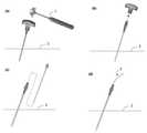
다음으로, 도 14를 참조하여 본 발명에 따른 의료용 니들장치의 사용방법에 대하여 설명한다. 먼저 도 14의 (a)에 도시된 바와 같이 상기 핸들(100)에 상기 니들어셈블리(12)가 고정상태로 채결된 의료용 니들장치(10)를 조직(2)에 삽입한다. 이때, 상기 핸들(100)의 상단에 형성된 타격자리(140)를 말렛(1) 등으로 타격하여 삽입한다.Next, a method of using the medical needle device according to the present invention will be described with reference to FIG. 14 . First, as shown in (a) of FIG. 14 , the
삽입이 완료되면 도 14의 (b) 및 (c)에 도시된 바와 같이 상기 핸들부(11)를 쥔 상태에서 상기 락킹노브(200)를 회전시켜 상기 핸들(100)과 상기 니들어셈블리(12)를 분리한 후, 상기 외관부(400)로부터 상기 니들부(500)를 분리한다. 상기 니들부(500)를 상기 외관부로부터 분리하고 도 14의 (d)에 도시된 바와 같이 상기 외관(402) 내부로 가이드 와이어(3)를 삽입하고, 상기 가이드 와이어(3)가 조직(2)에 삽입된 후에는 상기 외관부(400)를 조직으로부터 제거한다.When the insertion is completed, the
또다른 사용방법으로, 상기 도 14에서 (c)와 같이 상기 외관부(400)로부터 상기 니들부(500)를 분리한 후에, 상기 외관부(400)를 통하여 약물 등을 주입하거나 상기 니들(502)을 대신하여 조직(2)을 채취할 수 있는 채취장치(미도시) 등을 상기 외관부(400)를 통해서 삽입하여 원하는 조직을 채취할 수 있다.As another method of use, after separating the
또한, 상기 외관부(400)를 조직(2)으로부터 분리할 때, 분리가 용이하지 않으면 먼저 상기 핸들부(11)를 상기 외관부(400)에 결합한 후 분리할 수 있다.In addition, when separating the
상기와 같이, 본 발명의 바람직한 실시예를 참조하여 설명하였지만 해당 기술 분야의 숙련된 당업자라면 하기의 특허청구범위에 기재된 본 발명의 사상 및 영역으로부터 벗어나지 않는 범위 내에서 본 발명을 다양하게 수정 및 변경시킬 수 있음을 이해할 수 있을 것이다.As described above, although described with reference to preferred embodiments of the present invention, those skilled in the art can variously modify and change the present invention within the scope without departing from the spirit and scope of the present invention described in the claims below. You will understand that it can be done.
본 발명을 통하여, 핸들에 니들을 흔들림 없이 고정시킬 수 있어서 종래보다 안정적으로 수술할 수 있어 의사의 수고를 줄일 수 있을 뿐만 아니라, 간편한 조작만으로도 장치의 잠금 및 풀림을 쉽게 제어할 수 있는 장점을 가지므로, 해당분야에서 널리 쓰일 수 있을 것으로 예상된다.Through the present invention, the needle can be fixed to the handle without shaking, so that the operation can be performed more stably than in the prior art, thereby reducing the effort of the doctor and having the advantage of easily controlling the locking and unlocking of the device with simple manipulation. Therefore, it is expected to be widely used in the relevant field.
10 : 의료용 니들장치 11 : 핸들부
12 : 니들어셈블리 100 : 핸들
111, 112 : 이동제한홈 120 : 핸들수용부
130 : 제1결합부 140 : 타격자리
150 : 제1마킹부 160 : 프레임
170 : 두부 200 : 락킹노브
211, 212 : 락킹돌출부 221, 222 : 제2고정유지부
230 : 제2결합부 240 : 미끄럼방지부
250 : 삽입홀 260 : 바닥부
261 : 가세부 400 : 외관부
401 : 외관고정부 402 : 외관
403 : 테이퍼부 410 : 제1체결부
411 : 체결나사 412 : 제1체결홈
420 : 몸통부 421 : 제1파지홈
422 : 제1고정유지부 430 : 노출파지부
431 : 제1파지부 432 : 튜브커넥터
441 : 내부홀 501 : 니들고정부 510 : 제2파지부 511 : 제2파지홈 512 : 제2마킹부 520 : 삽입부 530 : 제2체결부 531, 532 : 제2돌기 1 : 말렛(mallet) 2 : 조직 3 : 가이드 와이어10: medical needle device 11: handle part
12: needle assembly 100: handle
111, 112: movement restriction groove 120: handle receiving part
130: first coupling unit 140: striking seat
150: first marking unit 160: frame
170: tofu 200: locking knob
211, 212: locking
230: second coupling part 240: non-slip part
250: insertion hole 260: bottom
261: attaching part 400: exterior part
401: exterior fixing part 402: exterior
403: tapered part 410: first fastening part
411: fastening screw 412: first fastening groove
420: body 421: first gripping groove
422: first fixed holding part 430: exposed holding part
431: first gripping part 432: tube connector
441: inner hole 501: needle fixing part 510: second gripping part 511: second gripping groove 512: second marking part 520: insertion part 530:
Claims (12)
Translated fromKorean상기 락킹노브의 삽입홀에 적어도 일부가 삽입되는 니들어셈블리를 포함하고,
상기 락킹노브의 회전에 의해 상기 삽입홀의 단면형상과 상기 니들어셈블리의 삽입된 부분 중 최하단의 단면형상을 서로 엇갈리게 하여 상기 삽입홀 내에서 상기 니들어셈블리의 부분이 고정되며,
상기 핸들의 상기 락킹노브와 결합되는 제1결합부에는 상기 락킹노브에 형성된 이동제한부가 연결되는 제한자리부가 형성되어, 상기 핸들과 락킹노브의 상대운동의 각범위를 한정하는 것을 특징으로 하는 의료용 니들장치.
a handle portion having a handle and a locking knob rotatably fixed to the handle; and
and a needle assembly in which at least a part is inserted into the insertion hole of the locking knob,
By rotating the locking knob, the cross-sectional shape of the insertion hole and the cross-sectional shape of the lowermost end of the inserted part of the needle assembly are crossed with each other, and the part of the needle assembly is fixed in the insertion hole,
Medical needle, characterized in that the first coupling portion coupled to the locking knob of the handle is formed with a limiting seat portion to which the movement limiting portion formed on the locking knob is connected, thereby limiting the angular range of relative motion between the handle and the locking knob. Device.
상기 니들어셈블리는,
중공의 외관;
상기 외관의 일단에 고정되는 외관고정부;
상기 외관의 내부에 삽입되는 니들; 및
상기 니들의 일단에 고정되고, 상기 외관고정부에 착탈가능한 니들고정부를
포함하고,
상기 니들고정부가 장착된 상태에서 상기 외관고정부의 적어도 일부분이 상기 삽입홀을 통해 상기 락킹노브 내에 삽입되는 것을 특징으로 하는 의료용 니들장치.
According to claim 1,
The needle assembly is
hollow appearance;
an exterior fixing part fixed to one end of the exterior;
a needle inserted into the interior of the exterior; and
A needle fixing part fixed to one end of the needle and detachable from the external fixing part
including,
In a state in which the needle fixing part is mounted, at least a portion of the external fixing part is inserted into the locking knob through the insertion hole.
[Claim 3] The medical needle device according to claim 2, wherein a fastening screw is formed at an end of the exterior fixing part opposite to the exterior.
[Claim 3] The medical needle device according to claim 2, wherein the lower end of the external fixing part has an exposed holding part exposed to the outside of the insertion hole.
[Claim 2] The medical needle device according to claim 1, wherein a striking seat capable of striking is formed at the upper end of the handle.
[Claim 6] The medical needle device according to claim 5, wherein a marking portion for confirming the direction of the needle is formed at the hitting seat.
The medical needle device according to claim 2, wherein a handle receiving portion communicating with the inside of the locking knob is formed inside the handle, and a handle receiving portion is formed in which a part of the external fixing portion is seated in a state in which the needle fixing portion is mounted.
The medical needle device according to claim 1, wherein the movement limiting part is one or more locking protrusions protruding from the locking knob, and the limiting seat part is a movement limiting groove concave and formed at a predetermined angle.
[Claim 3] The medical needle device according to claim 2, wherein a biasing part is formed on the locking knob to bias the external fixing part upward.
The medical needle device according to claim 10, wherein the biasing part is a tapered part formed around the insertion hole of the locking knob, and when the locking knob is rotated, the lower surface of the external fixing part is pushed upward.
Priority Applications (3)
| Application Number | Priority Date | Filing Date | Title |
|---|---|---|---|
| KR1020190179618AKR102360346B1 (en) | 2019-12-31 | 2019-12-31 | Medical Needle Apparatus |
| US17/789,910US20230062346A1 (en) | 2019-12-31 | 2020-11-05 | Medical needle device |
| PCT/KR2020/015387WO2021137412A1 (en) | 2019-12-31 | 2020-11-05 | Medical needle device |
Applications Claiming Priority (1)
| Application Number | Priority Date | Filing Date | Title |
|---|---|---|---|
| KR1020190179618AKR102360346B1 (en) | 2019-12-31 | 2019-12-31 | Medical Needle Apparatus |
Publications (2)
| Publication Number | Publication Date |
|---|---|
| KR20210085988A KR20210085988A (en) | 2021-07-08 |
| KR102360346B1true KR102360346B1 (en) | 2022-02-10 |
Family
ID=76685937
Family Applications (1)
| Application Number | Title | Priority Date | Filing Date |
|---|---|---|---|
| KR1020190179618AActiveKR102360346B1 (en) | 2019-12-31 | 2019-12-31 | Medical Needle Apparatus |
Country Status (3)
| Country | Link |
|---|---|
| US (1) | US20230062346A1 (en) |
| KR (1) | KR102360346B1 (en) |
| WO (1) | WO2021137412A1 (en) |
Family Cites Families (20)
| Publication number | Priority date | Publication date | Assignee | Title |
|---|---|---|---|---|
| US4266555A (en)* | 1979-11-09 | 1981-05-12 | Khosrow Jamshidi | Biopsy needle with stylet and cannula orientation |
| US5372583A (en)* | 1992-11-25 | 1994-12-13 | Cardiopulmonary Specialities, Inc. | Bone marrow infuser and method of use |
| US6241734B1 (en) | 1998-08-14 | 2001-06-05 | Kyphon, Inc. | Systems and methods for placing materials into bone |
| US6749576B2 (en)* | 1996-01-26 | 2004-06-15 | Allegiance Corporation | Biopsy device with adjustable sampling |
| US6221029B1 (en)* | 1999-05-13 | 2001-04-24 | Stryker Corporation | Universal biopsy system |
| US6554778B1 (en)* | 2001-01-26 | 2003-04-29 | Manan Medical Products, Inc. | Biopsy device with removable handle |
| US7811260B2 (en)* | 2002-05-31 | 2010-10-12 | Vidacare Corporation | Apparatus and method to inject fluids into bone marrow and other target sites |
| EP2039298B1 (en)* | 2002-05-31 | 2017-10-25 | Vidacare LLC | Apparatus to access bone marrow |
| US11298202B2 (en)* | 2002-05-31 | 2022-04-12 | Teleflex Life Sciences Limited | Biopsy devices and related methods |
| US20040077973A1 (en)* | 2002-10-22 | 2004-04-22 | Groenke Gregory C. | Biopsy device handle assembly |
| US20060276747A1 (en)* | 2005-06-06 | 2006-12-07 | Sherwood Services Ag | Needle assembly with removable depth stop |
| US8944069B2 (en)* | 2006-09-12 | 2015-02-03 | Vidacare Corporation | Assemblies for coupling intraosseous (IO) devices to powered drivers |
| WO2009059236A2 (en)* | 2007-10-31 | 2009-05-07 | Kim Stanley I | Rotating biopsy device and biopsy robot |
| US20090131827A1 (en)* | 2007-11-21 | 2009-05-21 | Stemcor Systems, Inc. | Apparatus and methods for tissue disruption |
| KR20090110983A (en) | 2008-04-21 | 2009-10-26 | 김희진 | Bone Cement Injection Kit |
| US9615816B2 (en)* | 2013-03-15 | 2017-04-11 | Vidacare LLC | Drivers and drive systems |
| US9968373B1 (en)* | 2014-02-21 | 2018-05-15 | Surgentec, Llc | Handles for needle assemblies |
| US10307142B2 (en)* | 2015-10-28 | 2019-06-04 | Abul Bashar Mohammad Anwarul Islam | Biopsy needle |
| WO2017186794A1 (en)* | 2016-04-28 | 2017-11-02 | Prometheus Delta Tech Ltd | An intraosseous device |
| US11839403B2 (en)* | 2017-02-06 | 2023-12-12 | Distal Access, Llc | Tissue piercing assemblies |
- 2019
- 2019-12-31KRKR1020190179618Apatent/KR102360346B1/enactiveActive
- 2020
- 2020-11-05USUS17/789,910patent/US20230062346A1/enactivePending
- 2020-11-05WOPCT/KR2020/015387patent/WO2021137412A1/ennot_activeCeased
Also Published As
| Publication number | Publication date |
|---|---|
| US20230062346A1 (en) | 2023-03-02 |
| KR20210085988A (en) | 2021-07-08 |
| WO2021137412A1 (en) | 2021-07-08 |
Similar Documents
| Publication | Publication Date | Title |
|---|---|---|
| US6554778B1 (en) | Biopsy device with removable handle | |
| US12318096B2 (en) | Screw guide and tissue retractor instrument | |
| US9962211B2 (en) | Handheld instrument assembly | |
| US10111650B2 (en) | Pedicle mountable retractor system | |
| US9788812B2 (en) | Needle guide with selectable aspects | |
| US6524238B2 (en) | Universal handle and method for use | |
| EP1811912B1 (en) | Cervical bone preparation tool and implant guide systems | |
| US5665092A (en) | Marker for surgical procedures | |
| CN108420464B (en) | Biopsy sampling device | |
| JPH10506022A (en) | Device for mechanically aligning a bone screw in an intramedullary nail member | |
| TW201436757A (en) | Coupling assembly and bone fixation device for connecting a rod to a bone fixation element | |
| CN109310483B (en) | Cannula lock with rotational brake and anchor deployed into bone in which the cannula lock is disposed | |
| US9924981B2 (en) | Minimally-invasive surgery pedicle screw and rod assembly, inserter tool, and insertion method for use in spinal stabilization procedures | |
| EP2906132B1 (en) | Fixing means for fixation of bone fragments at bone fractures | |
| KR102360346B1 (en) | Medical Needle Apparatus | |
| US9545260B2 (en) | Minimally invasive device for surgical operations | |
| WO2017137974A1 (en) | Bone needle clamps and cannulated needle pins for use as skeletal infusion needles and methods therein | |
| JP2012232044A (en) | Puncture needle for bone cement injection, handle holder, and bone cement injection needle set | |
| JP2013009711A (en) | Instrument for placing puncture needle | |
| CN215739264U (en) | Tibial chisel for anterior cruciate ligament reconstruction | |
| KR101863741B1 (en) | Patient-Specific Artificial Shoulder Joint Surgical Instruments | |
| KR200475860Y1 (en) | Injection Needle | |
| KR102229383B1 (en) | Medical needle | |
| US6524306B1 (en) | Lock device for surgical instruments | |
| CN223416299U (en) | Navigation handle convenient for operating reset nail |
Legal Events
| Date | Code | Title | Description |
|---|---|---|---|
| PA0109 | Patent application | Patent event code:PA01091R01D Comment text:Patent Application Patent event date:20191231 | |
| PA0201 | Request for examination | ||
| E902 | Notification of reason for refusal | ||
| PE0902 | Notice of grounds for rejection | Comment text:Notification of reason for refusal Patent event date:20210630 Patent event code:PE09021S01D | |
| PG1501 | Laying open of application | ||
| E701 | Decision to grant or registration of patent right | ||
| PE0701 | Decision of registration | Patent event code:PE07011S01D Comment text:Decision to Grant Registration Patent event date:20211104 | |
| PR0701 | Registration of establishment | Comment text:Registration of Establishment Patent event date:20220204 Patent event code:PR07011E01D | |
| PR1002 | Payment of registration fee | Payment date:20220207 End annual number:3 Start annual number:1 | |
| PG1601 | Publication of registration | ||
| PR1001 | Payment of annual fee | Payment date:20250204 Start annual number:4 End annual number:4 |