KR102359616B1 - Devices for towing internal organ for surgery - Google Patents
Devices for towing internal organ for surgeryDownload PDFInfo
- Publication number
- KR102359616B1 KR102359616B1KR1020200059472AKR20200059472AKR102359616B1KR 102359616 B1KR102359616 B1KR 102359616B1KR 1020200059472 AKR1020200059472 AKR 1020200059472AKR 20200059472 AKR20200059472 AKR 20200059472AKR 102359616 B1KR102359616 B1KR 102359616B1
- Authority
- KR
- South Korea
- Prior art keywords
- traction
- support
- flat tube
- upper half
- chamber
- Prior art date
- Legal status (The legal status is an assumption and is not a legal conclusion. Google has not performed a legal analysis and makes no representation as to the accuracy of the status listed.)
- Active
Links
- 238000001356surgical procedureMethods0.000titleclaimsabstractdescription34
- 210000001835visceraAnatomy0.000titleclaimsdescription9
- 210000000056organAnatomy0.000claimsabstractdescription30
- 210000003815abdominal wallAnatomy0.000claimsabstractdescription20
- 238000005452bendingMethods0.000claimsdescription18
- 238000003780insertionMethods0.000claimsdescription11
- 230000037431insertionEffects0.000claimsdescription11
- 238000000034methodMethods0.000claimsdescription4
- 210000000936intestineAnatomy0.000abstractdescription8
- 210000000683abdominal cavityAnatomy0.000description6
- 238000002357laparoscopic surgeryMethods0.000description5
- 210000001015abdomenAnatomy0.000description3
- 230000002745absorbentEffects0.000description2
- 239000002250absorbentSubstances0.000description2
- 230000002439hemostatic effectEffects0.000description2
- 230000007774longtermEffects0.000description2
- 208000032544CicatrixDiseases0.000description1
- 229920000742CottonPolymers0.000description1
- 229910000976Electrical steelInorganic materials0.000description1
- 208000004550Postoperative PainDiseases0.000description1
- 238000010521absorption reactionMethods0.000description1
- 230000000740bleeding effectEffects0.000description1
- 210000004369bloodAnatomy0.000description1
- 239000008280bloodSubstances0.000description1
- 210000001124body fluidAnatomy0.000description1
- 239000010839body fluidSubstances0.000description1
- 230000006835compressionEffects0.000description1
- 238000007906compressionMethods0.000description1
- 238000002316cosmetic surgeryMethods0.000description1
- 238000005553drillingMethods0.000description1
- 229920001971elastomerPolymers0.000description1
- 230000005484gravityEffects0.000description1
- 238000003384imaging methodMethods0.000description1
- 210000003734kidneyAnatomy0.000description1
- 238000002350laparotomyMethods0.000description1
- 210000004185liverAnatomy0.000description1
- 239000000463materialSubstances0.000description1
- 230000007246mechanismEffects0.000description1
- 238000012986modificationMethods0.000description1
- 230000004048modificationEffects0.000description1
- 230000001681protective effectEffects0.000description1
- 239000005060rubberSubstances0.000description1
- 231100000241scarToxicity0.000description1
- 230000037387scarsEffects0.000description1
- 239000010703siliconSubstances0.000description1
- 229910001220stainless steelInorganic materials0.000description1
- 239000010935stainless steelSubstances0.000description1
- 210000002784stomachAnatomy0.000description1
- 229920003002synthetic resinPolymers0.000description1
- 239000000057synthetic resinSubstances0.000description1
- 230000009278visceral effectEffects0.000description1
Images


Classifications
- A—HUMAN NECESSITIES
- A61—MEDICAL OR VETERINARY SCIENCE; HYGIENE
- A61B—DIAGNOSIS; SURGERY; IDENTIFICATION
- A61B17/00—Surgical instruments, devices or methods
- A61B17/02—Surgical instruments, devices or methods for holding wounds open, e.g. retractors; Tractors
- A61B17/0218—Surgical instruments, devices or methods for holding wounds open, e.g. retractors; Tractors for minimally invasive surgery
- A—HUMAN NECESSITIES
- A61—MEDICAL OR VETERINARY SCIENCE; HYGIENE
- A61B—DIAGNOSIS; SURGERY; IDENTIFICATION
- A61B17/00—Surgical instruments, devices or methods
- A61B17/02—Surgical instruments, devices or methods for holding wounds open, e.g. retractors; Tractors
- A61B2017/0212—Cushions or pads, without holding arms, as tissue retainers, e.g. for retracting viscera
- A—HUMAN NECESSITIES
- A61—MEDICAL OR VETERINARY SCIENCE; HYGIENE
- A61B—DIAGNOSIS; SURGERY; IDENTIFICATION
- A61B17/00—Surgical instruments, devices or methods
- A61B17/02—Surgical instruments, devices or methods for holding wounds open, e.g. retractors; Tractors
- A61B17/0218—Surgical instruments, devices or methods for holding wounds open, e.g. retractors; Tractors for minimally invasive surgery
- A61B2017/0225—Surgical instruments, devices or methods for holding wounds open, e.g. retractors; Tractors for minimally invasive surgery flexible, e.g. fabrics, meshes, or membranes
- A—HUMAN NECESSITIES
- A61—MEDICAL OR VETERINARY SCIENCE; HYGIENE
- A61B—DIAGNOSIS; SURGERY; IDENTIFICATION
- A61B17/00—Surgical instruments, devices or methods
- A61B17/02—Surgical instruments, devices or methods for holding wounds open, e.g. retractors; Tractors
- A61B2017/0287—Surgical instruments, devices or methods for holding wounds open, e.g. retractors; Tractors with elastic retracting members connectable to a frame, e.g. hooked elastic wires
Landscapes
- Health & Medical Sciences (AREA)
- Life Sciences & Earth Sciences (AREA)
- Surgery (AREA)
- Heart & Thoracic Surgery (AREA)
- Engineering & Computer Science (AREA)
- Biomedical Technology (AREA)
- Nuclear Medicine, Radiotherapy & Molecular Imaging (AREA)
- Medical Informatics (AREA)
- Molecular Biology (AREA)
- Animal Behavior & Ethology (AREA)
- General Health & Medical Sciences (AREA)
- Public Health (AREA)
- Veterinary Medicine (AREA)
- Surgical Instruments (AREA)
Abstract
Translated fromKoreanDescription
Translated fromKorean본 발명은 수술 시 사용되는 내장 견인장치에 관한 것으로서, 보다 상세하게는, 수술대상 부위를 가리고 있는 내장을 움직여 수술 시야를 확보해 줌으로써 정확한 수술을 진행할 수 있게 하는 수술시 인체 장기를 견인하기 위한 견인장치에 관한 것이다.The present invention relates to a visceral traction device used during surgery, and more particularly, traction for traction of human organs during surgery that enables accurate surgery by moving the intestines covering the surgical target site to secure the surgical field of view It's about the device.
환자의 복부를 절개하는 개복수술은, 일단 출혈이 심하고 수술 후 회복에 시간이 오래 걸리며 흉터를 남긴다는 단점을 가진다. 이러한 개복 수술의 단점을 극복하기 위해, 복강경 수술도구를 이용한 복강경 수술 방법이 개발 및 연구되고 있다.Laparotomy, in which an incision is made in the patient's abdomen, has disadvantages in that it bleeds heavily, takes a long time to recover after surgery, and leaves scars. In order to overcome such disadvantages of open surgery, a laparoscopic surgery method using a laparoscopic surgical tool is being developed and studied.
복강경수술(腹腔鏡手術)은, 복부의 여러 곳에 수술용 구멍을 천공하고, 각 구멍을 통해, 내시경과, 가늘고 길게 형성된 수술도구 들을 삽입한 후, 영상촬영장치 등의 도움을 받아 진행하는 수술이다. 복강경수술은 개복수술에 비해 절개부위가 현저히 작고 출혈의 적으며 수술 후 통증도 덜하다. 의료장비의 발전에 따라 과거의 개복수술이 복강경 수술로 점차 대체되고 있다.Laparoscopic surgery (腹腔鏡手術) is a surgery performed with the help of an imaging device after drilling surgical holes in various places in the abdomen, inserting an endoscope and long and thin surgical instruments through each hole. . Compared to open surgery, laparoscopic surgery has a significantly smaller incision, less bleeding, and less post-operative pain. With the development of medical equipment, the past open surgery is gradually being replaced by laparoscopic surgery.
그런데, 복강경수술에는, 환자 복부 내의 장기(臟器)의 위치를 어느 정도 움직여야 시야가 확보되는 경우가 많다. 장기가 중력의 영향을 받아 대부분 아래쪽으로 쳐져 있기 때문이다. 장기를 들어 올려야, 수술 대상 부위에 대한 시야가 확보되고 수술도구의 접근이 가능하여 정확한 수술이 가능한 것이다.However, in laparoscopic surgery, there are many cases in which the field of view is secured only when the position of the organs in the patient's abdomen is moved to some extent. This is because the organs are mostly drooping downward under the influence of gravity. When the organ is lifted, the field of view of the surgical target area is secured and the surgical tools are accessible, so accurate surgery is possible.
이에 따라, 장기를 보다 효율적으로 들어올리기 위한, 다양한 수술용 견인기구가 제안된 바 있다. 가령, 국내 등록특허공보 제10-1156229호에는, 엠보싱 구조를 갖는 장기 견인 지혈장치가 개지되어 있다. 개시된 장치는, 수술부위에 위치하여 신체 장기를 지지하는 지지부재; 상기 지지부재를 둘러싸고 혈액 또는 체액을 흡수하는 흡수부재; 및 상기 흡수부재를 둘러싸고 상기 신체 장기와 접촉하는 보호막부재를 포함하고, 상기 흡수부재는 엠보싱 구조를 갖는 특징을 갖는다.Accordingly, in order to more efficiently lift the organs, various surgical traction mechanisms have been proposed. For example, in Korean Patent Registration No. 10-1156229, a long-term traction hemostatic device having an embossed structure is disclosed. The disclosed device includes a support member positioned at a surgical site to support body organs; an absorption member surrounding the support member and absorbing blood or body fluid; and a protective film member surrounding the absorbent member and contacting the body organs, wherein the absorbent member has an embossed structure.
또한, 국내 등록특허공보 제10-1293282호에는, 체내에 삽입되는 이동몸체부; 체내에서 상기 이동몸체부와 연결되고, 체내의 대상체를 견인하는 후크부; 및 체외에서 상기 이동몸체부의 체내 이동을 조작하고, 자석부를 구비하는 조작부를 포함하고, 상기 이동몸체부는 상기 조작부의 이동에 연동하여 체내에서 이동되도록 상기 자석부에 달라붙는 재질을 포함하여 이루어지며, 상기 후크부는, 일측이 상기 이동몸체부와 연결되는 스트링부; 및 상기 스트링부의 타측에 연결되고, 상기 대상체를 후킹하는 후크를 포함하고, 상기 조작부의 체외에서의 이동에 따른 상기 이동몸체부의 체내에서의 이동 시, 상기 대상체를 후킹한 후크와 상기 이동몸체부에 각각 연결된 상기 스트링부에 장력이 형성됨에 따라 상기 후크는 상기 대상체를 견인하는 수술용 견인장치가 개시된 바 있다.In addition, in Korean Patent No. 10-1293282, a movable body part inserted into the body; a hook part connected to the movable body part in the body and pulling the object in the body; and a manipulation unit having a magnet unit for manipulating the movement of the mobile body part from outside the body, and the moving body part is made of a material attached to the magnet part to move in the body in conjunction with the movement of the manipulation part, The hook part may include: a string part having one side connected to the movable body part; and a hook connected to the other side of the string part for hooking the object, wherein when the movable body part moves in the body according to the movement of the operation part outside the body, the hook hooking the object and the movable body part A surgical traction device has been disclosed in which the hook pulls the object as tension is formed in each of the connected string parts.
본 발명은 상기 문제점을 해소하고자 창출한 것으로서, 구조가 간단하고 가벼워 취급이 용이함은 물론, 잡고 있을 필요가 없어 사용이 편리한 수술시 인체 장기를 견인하기 위한 견인장치를 제공함에 목적이 있다.The present invention was created to solve the above problems, and it is an object of the present invention to provide a traction device for traction of human organs during surgery, which has a simple and light structure and is easy to handle as well as convenient to use because there is no need to hold it.
상기 목적을 달성하기 위한 과제의 해결수단으로서의 본 발명의 수술시 인체 장기를 견인하기 위한 견인장치는, 일정길이를 가지는 지지부와, 상기 지지부의 양단에 이어지며 길이방향으로 연장되고 코그가 형성되어 있는 인장부로 구성된 견인실과; 상기 각 인장부의 선단에 고정되며, 사용 시 복벽을 안쪽에서 바깥쪽으로 통과하여, 상기 인장부가 복벽에 걸려 있는 상태를 유지하게 하는 바늘과; 상기 지지부에 지지된 상태로, 견인실에 당겨져, 내장을 받쳐 올리는 써포트부재를 포함한다.The traction device for traction of a human organ during surgery of the present invention as a means of solving the problem for achieving the above object includes a support portion having a predetermined length, connected to both ends of the support portion, extending in the longitudinal direction, and a cog is formed a traction chamber composed of a tension part; a needle fixed to the tip of each tension part and passing through the abdominal wall from the inside to the outside when in use to keep the tension part hanging on the abdominal wall; In a state supported by the support, it is pulled to the traction chamber, and includes a support member to support the intestines.
또한, 상기 써포트부재는; 일정직경을 갖는 중공튜브의 형태를 취하며, 상기 견인실을 내부로 통과시키는 원통튜브이다.In addition, the support member; It takes the form of a hollow tube having a certain diameter, and is a cylindrical tube that passes the traction chamber inside.
아울러, 상기 써포트부재는; 일정폭 및 길이를 가지고 폭방향 양단부가 일체를 이루는 상측반부 및 하측반부와, 상기 상측반부의 중앙부에 위치하고 상기 견인실을 통과시키는 통로를 제공하는 견인실수용부와, 상기 상측반부의 상면에 형성되며, 내장에 대한 미끄러짐을 방지하는 미끄럼방지돌출부를 포함하는 플랫튜브이다.In addition, the support member; An upper half and a lower half having a certain width and length and both ends in the width direction are integrally formed, a traction chamber receiving portion located in the central portion of the upper half and providing a passage through the traction chamber, is formed on the upper surface of the upper half , It is a flat tube including a non-slip protrusion to prevent slipping on the interior.
또한, 상기 써포트부재는; 일정폭 및 길이를 가지고 폭방향 양단부가 일체를 이루는 상측반부 및 하측반부와, 상측반부의 중앙부 저면에 형성되고 하측반부를 향해 개방되며 상기 견인실을 수용하는 탄력홀더와, 상기 하측반부의 중앙부 상면에 위치하고 탄력홀더에 대응하며, 외력을 받아 상기 탄력홀더에 끼워져, 탄력홀더에 수용되어 있는 견인실을 탄력홀더 내에 압박 고정시키는 삽입록커와, 상기 상측반부의 상면에 형성되며, 내장에 대한 미끄러짐을 방지하는 미끄럼방지돌출부를 구비하는 플랫튜브이다.In addition, the support member; An upper half and a lower half having a predetermined width and length and forming an integral part at both ends in the width direction, a resilient holder formed on the lower surface of the central part of the upper half and opened toward the lower half to accommodate the traction chamber, and the upper surface of the central part of the lower half An insertion locker located in and corresponding to the resilient holder and fitted into the resilient holder by receiving an external force to press and fix the traction chamber accommodated in the resilient holder in the resilient holder, and is formed on the upper surface of the upper half, and prevents the internal sliding It is a flat tube having an anti-slip protrusion to prevent it.
그리고, 상기 플랫튜브에는, 플랫튜브의 길이방향으로 일정 간격을 이루며, 플랫튜브를 벤딩 시킬 때 벌어지는 벤딩허용슬릿이 다수 형성된다.In addition, a plurality of bending allowable slits are formed in the flat tube at regular intervals in the longitudinal direction of the flat tube and open when the flat tube is bent.
상기와 같이 이루어지는 본 발명의 수술시 인체 장기를 견인하기 위한 견인장치는, 구조가 간단하고 가벼워 취급이 용이함은 물론, 세팅된 자세를 안정적으로 유지하므로 잡고 있을 필요가 없어 편리하다.The traction device for traction of human organs during surgery of the present invention made as described above has a simple and light structure and is easy to handle, as well as stably maintaining a set posture, which is convenient because there is no need to hold it.
도 1은 본 발명의 일 실시예에 따른 수술시 인체 장기를 견인하기 위한 견인장치의 컨셉을 설명하기 위한 도면이다.
도 2는 본 발명의 일 실시예에 따른 수술시 인체 장기를 견인하기 위한 견인장치의 사시도이다.
도 3은 본 발명의 일 실시예에 따른 수술시 인체 장기를 견인하기 위한 견인장치의 다른 예를 도시한 사시도이다.
도 4는 본 발명의 일 실시예에 따른 수술시 인체 장기를 견인하기 위한 견인장치의 또 다른 예를 도시한 도면이다.
도 5는 도 4의 A-A선 단면도이다.
도 6은 본 발명의 일 실시예에 따른 수술시 인체 장기를 견인하기 위한 견인장치의 또 다른 예를 도시한 도면이다.
도 7은 도 6의 B-B선 단면도이다.
도 8은 도 6에 도시한 탄력홀더에 삽입록커가 결합한 모습을 도시한 단면도이다.1 is a view for explaining the concept of a traction device for pulling a human organ during surgery according to an embodiment of the present invention.
2 is a perspective view of a traction device for pulling a human organ during surgery according to an embodiment of the present invention.
3 is a perspective view illustrating another example of a traction device for traction of human organs during surgery according to an embodiment of the present invention.
4 is a view showing another example of a traction device for pulling a human organ during surgery according to an embodiment of the present invention.
5 is a cross-sectional view taken along line AA of FIG. 4 .
6 is a view showing another example of a traction device for pulling a human organ during surgery according to an embodiment of the present invention.
7 is a cross-sectional view taken along line BB of FIG. 6 .
8 is a cross-sectional view showing a state in which the insert locker is coupled to the elastic holder shown in FIG.
이하, 본 발명에 따른 하나의 실시예를 첨부된 도면을 참조하여 보다 상세히 설명하기로 한다.Hereinafter, one embodiment according to the present invention will be described in more detail with reference to the accompanying drawings.
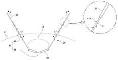
도 1은 본 발명의 일 실시예에 따른 수술시 인체 장기를 견인하기 위한 견인장치(20)의 컨셉을 설명하기 위한 도면이다.1 is a view for explaining the concept of a
본 실시예에 따른 수술시 인체 장기를 견인하기 위한 견인장치(20)는 수술 시, 수술 대상부위를 가리고 있는 내장(13)을 옆이나 위로 움직임으로써 수술 시야를 제공하는 목적을 가지는 것이다. 상기 내장(13)은 간이나 위나 신장 등을 포함하는 복강 내 장기(臟器)를 의미한다.The
수술시 인체 장기를 견인하기 위한 견인장치(20)는, 내장(13)를 받쳐 지지하는 다수의 써포트부재(50), 써포트부재(50)와 연결되고 복벽(11)을 통과해 외부로 당겨지는 견인실(40), 견인실(40)의 양단부에 고정되는 바늘(30)의 기본 구성을 갖는다.The
써포트부재(50)는 도 2 내지 도 8에 도시한 다양한 형태를 가질 수 있으며, 합성수지나 코튼(cotton) 또는 고무나 실리콘, 경우에 따라 스테인리스스틸 등으로 제작 가능하다.The
견인실(40)은, 중앙의 지지부(43)와, 지지부(43)의 양단에 일체를 이루는 인장부(41)로 이루어진다. 인장부(41)에는 코그(cog, 41a)가 형성되며 복벽(11)에 걸려 고정된다. 바늘(30)을 화살표 a방향으로 당김에 따라 인장부(41)는 복벽(11)을 통과해 외부로 당겨지고 내장(13)은 상부로 견인된다. 인장부(41)는, 체외로 인출되기는 하지만, 코그(41a)의 작용에 의해 복강 내부로 다시 딸려 들어가지 않는다.The
도 2는 본 발명의 일 실시예에 따른 수술시 인체 장기를 견인하기 위한 견인장치(20)의 사시도이다.2 is a perspective view of a
도시한 바와 같이, 본 실시예에 따른 수술시 인체 장기를 견인하기 위한 견인장치(20)는, 견인실(40), 두 개의 바늘(30), 써포트부재(50)로서의 원통튜브(51)를 포함한다.As shown, the
견인실(40)은, 일정길이를 가지는 지지부(43)와, 지지부(43) 양단부에 이어지는 인장부(41)로 이루어진다.The
지지부(43)는 대부분이 내장(13)의 하부에 걸쳐지며 원통튜브(51)를 도 1의 화살표 b방향으로 받쳐 올린다. 또한 인장부(41)는 다수의 코그(cog, 41a)을 갖는 부분으로서, 지지부(43)의 양단에 일체를 이루며 길이방향으로 연장된다. 인장부(41)는 성형외과에서 사용하는 리프팅실과 갖는 구조를 가질 수 있다.The
인장부(41)는 바늘(30)을 도 1의 화살표 a방향으로 당길 때, 복벽(11)을 통과하여 외부로 인출되며 복벽(11)에 걸쳐진 상태를 유지한다. 인장부(41)는 코그(41a)의 작용에 의해, 화살표 c방향으로 다시 들어가지 않는다.When the
바늘(30)는 양측 인장부(41)의 선단에 고정되며, 사용 시 복벽(11)을 안쪽에서 바깥쪽으로 통과하여, 인장부(41)가 복벽(11)에 걸려 있는 상태를 유지하게 한다. 안쪽에서 바깥쪽으로 통과한다는 말의 의미는, 바늘이 복강의 내부에서 외부로 통과한다는 의미이다.The
원통튜브(51)는, 일정 직경을 갖는 중공형 부재로서 견인실통로(51a)를 제공한다. 견인실통로(51a)는 견인실(40) 중 지지부(43)를 수용하는 공간이다. 원통튜브(51)의 직경이나 길이는 필요에 따라 달라질 수 있다. 아울러, 원통튜브(51)의 적용 개수도 수술 여건에 따라 조절될 수 있다. 가령 한 개만 적용할 수도 있고, 두 개 이상 사용 할 수도 있는 것이다.The
도 3은 본 발명의 일 실시예에 따른 수술시 인체 장기를 견인하기 위한 견인장치(20)의 다른 예를 도시한 사시도이다.3 is a perspective view illustrating another example of the
이하, 상기한 도면부호와 동일한 도면부호는 동일한 기능의 동일한 부재를 가리킨다.Hereinafter, the same reference numerals as the above reference numerals indicate the same members having the same functions.
도 3에 도시한 견인장치(20)에서의 써포트부재(50)는 납작한 형상의 플랫튜브(53)이다. 플랫튜브(53)는, 말하자면, 원통형 튜브를 납작하게 눌러 놓은 모양을 갖는다.The
이러한 플랫튜브(53)는, 상측반부(53b) 및 하측반부(53c), 견인실수용부(53d), 미끄럼방지돌출부(53f))를 포함한다.The
상측반부(53b) 및 하측반부(53c)는, 일정폭 및 길이를 가지는 판상부재로서 폭방향 양단부가 일체를 이룬다. 상측반부(53b)는 상부로, 하측반부(53c)는 하부로 볼록하게 만곡된 형상을 취하며 사이공간부(53a)를 갖는다. 사이공간부(53a)는 상측반부(53b)와 하측반부(53c) 사이의 이격공간이다.The
견인실수용부(53d)는, 상측반부(53b)의 저면 중앙부에서 플랫튜브(53)의 길이방향으로 연장된 부분으로서 견인실(40)을 통과시키는 통로(53e)를 제공한다. 견인실수용부(53d)는 양단부가 개방된 미세 튜브의 형태를 취한다. 통로(53e) 내부에는 견인실의 지지부(43)가 수용된다.The traction chamber
미끄럼방지돌출부(53f)는 상측반부(53b)의 상면에 형성된 선형 돌기로서, 내장(內臟)에 대한 플랫튜브(53)의 미끄러짐을 방지하는 역할을 한다. 이러한 기능을 수행할 수 있는 한 미끄럼방지돌출부의 패턴은 얼마든지 달라질 수 있다.The
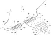
도 4는 본 발명의 일 실시예에 따른 수술시 인체 장기를 견인하기 위한 견인장치(20)의 또 다른 예를 도시한 도면이고, 도 5는 도 4의 A-A선 단면도이다.4 is a view showing another example of the
도면을 참조하면, 견인장치(20)의 플랫튜브(53)에 다수의 벤딩허용슬릿(53k)이 형성되어 있음을 알 수 있다. 벤딩허용슬릿(53k)은, 플랫튜브(53)를 화살표 f방향으로 벤딩 시킬 때 벌어짐으로써 플랫튜브(53)가 보다 용이하게 구부러질 수 있도록 적용된 것이다.Referring to the drawings, it can be seen that a plurality of bending
이러한 벤딩허용슬릿(53k)은, 이를테면, 일단부가 견인실수용부(53d)의 우측부분에서 출발하여 상측반부(53c)의 폭방향 외곽부로 연장된 후 내려가 하측반부를 거치고 다시 상승하여 상측반부(53c)로 올라와 견인실수용부(53d)의 좌측부분으로 연장된 형상을 취한다. 즉, 도 7에 도시한 형상을 취하는 것이다.This bending
벤딩허용슬릿(53k)은 플랫튜브(53)의 길이방향으로 일정 간격을 이룬다. 하지만, 필요에 따라, 벤딩허용슬릿(53k) 상호간의 간격을 달리 설계할 수도 있다.The bending allowable slit (53k) forms a predetermined interval in the longitudinal direction of the flat tube (53). However, if necessary, the interval between the bending
도 6은 본 발명의 일 실시예에 따른 수술시 인체 장기를 견인하기 위한 견인장치(20)의 또 다른 예를 도시한 도면이고, 도 7은 도 6의 B-B선 단면도이다. 그리고, 도 8은 도 6에 도시한 탄력홀더(55d)에 삽입록커(55h)가 결합한 모습을 도시한 단면도이다.6 is a view showing another example of the
도 6에 도시한 써포트부재(50)는, 상측반부(55b) 및 하측반부(55c), 탄력홀더(55d), 미끄럼방지돌출부(55m), 삽입록커(55h), 벤딩허용슬릿(55k)을 갖는다. 상측반부(55b)와 하측반부(55c)는, 위에 설명한 바와 마찬가지로, 일정폭 및 길이를 가지는 판상부재로서 폭방향 양단부가 일체를 이룬다. 상측반부(55b)는 상부로, 하측반부(55c)는 하부로 볼록하게 만곡된 형상을 취하며 사이공간부(55a)를 갖는다.The
탄력홀더(55d)는 상측반부(55b)의 저면 중앙부에서 플랫튜브(55)의 길이방향으로 연장된 부분으로서, 견인실(40)을 수용하는 압박공간(55e)을 갖는다. 압박공간(55e)은 하측반부(55c)를 향해 개방되며 외력에 의해 탄성 변형 가능하다. 압박공간(55e)에는 견인실(40) 중앙의 지지부(43)가 수용된다.The
미끄럼방지돌출부(55m)는 상측반부(55b)의 상면에 형성된 선형 돌기로서, 내장(內臟)에 대한 플랫튜브(55)의 미끄러짐을 방지하는 역할을 한다. 미끄럼방지돌출부의 형상은 얼마든지 변경 가능하다.The
아울러, 플랫튜브(55)의 길이방향을 따라 다수의 벤딩허용슬릿(55k)이 형성되어 있다. 벤딩허용슬릿(55k)은, 플랫튜브(53)를 벤딩 시킬 때 벌어짐으로써 플랫튜브(55)가 보다 용이하게 구부러질 수 있도록 적용된 것이다.In addition, a plurality of bending
벤딩허용슬릿(55k)은, 도 7에 도시한 바와 같이, 일단부가 탄력홀더(55d)의 우측부분에서 출발하여 상측반부(55b)의 폭방향 외곽부로 연장된 후 내려가 하측반부(55c)를 돌아 다시 상승하여 상측반부(55b)로 올라와 탄력홀더(55d)의 좌측부분으로 연장된 형상을 취한다. 벤딩허용슬릿(55k)은 플랫튜브(55)의 길이방향으로 일정 간격을 이루거나, 일정하지 않은 간격을 이룰 수 있다.The bending allowable slit (55k), as shown in Figure 7, one end starts from the right side of the elastic holder (55d) and extends to the outer portion in the width direction of the upper half (55b), then goes down and turns around the lower half (55c) It rises again and ascends to the upper half (55b) and takes a shape extending to the left side of the elastic holder (55d). The bending allowable slit (55k) may form a predetermined interval in the longitudinal direction of the flat tube (55), or may achieve a non-uniform interval.
삽입록커(55h)는, 하측반부(55c)의 상면 중앙에 위치하고 탄력홀더(55d)와 나란하게 연장된 선형 돌기이다. 삽입록커(55h)는 탄력홀더(55d)에 대응하며, 외력이 가해지지 않은 상태에서, 도 7에 도시한 바와 같이, 탄력홀더(55d)의 하단부에 밀착하고 있다. 이와 같이 탄력홀더(55d)의 압박공간(55e)이 삽입록커(55h)에 막혀 있으므로, 압박공간(55e)에 수용되어 있는 견인실(40)이 하부로 빠질 염려가 없다.The insertion locker (55h) is located in the center of the upper surface of the lower half (55c) and is a linear protrusion extending in parallel with the elastic holder (55d). Insert locker (55h) corresponds to the elastic holder (55d), in a state in which no external force is applied, as shown in Figure 7, is in close contact with the lower end of the elastic holder (55d). As described above, since the
삽입록커(55h)는, 상측반부(55b)와 하측반부(55c)를 화살표 P방향으로 가압할 때, 가압력을 받아 탄력홀더(55d)를 벌리고 압박공간(55e)에 끼워진다. 탄력홀더(55d)는 삽입록커(55h)가 압박공간(55e)에 삽입된 순간 다시 오므라져 삽입록커(55h)를 탄력적으로 수용한 상태를 유지한다. 이 때, 압박공간(55e)에 수용되어 있던 견인실의 지지부(43)는, 도 8에 도시한 바와 같이, 삽입록커(55h)에 의해 압박되어 고정된 상태가 된다.The
이와 같이, 지지부(43)에 대해 플랫튜브(55)를 고정시킬 수 있으므로, 가령, 지지부(43)가 한쪽으로 기울더라도 플랫튜브(55)가 미끄러져 내려가지 않는다. 수술 중 플랫튜브(55)가 불필요하게 움직이지 않아 보다 효율적인 사용이 가능한 것이다.In this way, since the
상기 구성을 갖는 본 실시예에 따른 수술시 인체 장기를 견인하기 위한 견인장치(20)의 사용 방법은 다음과 같다.The method of using the
먼저, 견인장치(20)를 환자의 복강 내부로 진입시킨다. 견인장치의 진입이 완료되었다면, 써포트부재(50)를, 내장(13) 받침 지점에 위치시키고, 내장을 움직일 방향을 고려하여, 바늘(30)을 복벽(11)의 내측에서 외측으로 통과시킨 후 도 1의 화살표 a방향으로 당긴다. 이 때 도 6에 도시한 타입의 플랫튜브(55)를 사용한 경우라면, 삽입록커(55h)를 이용해 견인실을 고정해 놓는다.First, the
바늘(30)을 당김에 따라, 견인실(40)이 복벽(11)을 통과하고, 복벽(11)이 인장부(41) 구간에 위치하게 된다. 그 동안 써포트부재(50)에 받쳐져 있는 내장(13)은 당겨지는 방향으로 움직인다. 내장이 충분히 움직였다면 화살표 a방향의 인장을 정지시킨다. 견인실(40)을 인장하지 않더라도 코그(41a)가 복벽(11)에 걸려, 견인실(40)이 다시 복강내로 들어갈 염려가 없다.As the
계획된 수술이 완료되었다면, 복강 내에 가위를 집어넣어 지지부(43)를 절단하고, 절단된 견인실(40)을 체외로 완전히 뽑아내고 써포트부재(50)도 꺼낸 후 수술을 마무리한다.If the planned operation is completed, the
이상, 본 발명을 구체적인 실시예를 통하여 상세하게 설명하였으나, 본 발명은 상기 실시예에 한정하지 않고, 본 발명의 기술적 사상의 범위 내에서 통상의 지식을 가진 자에 의하여 여러 가지 변형이 가능하다.As mentioned above, although the present invention has been described in detail through specific embodiments, the present invention is not limited to the above embodiments, and various modifications are possible by those of ordinary skill within the scope of the technical spirit of the present invention.
11:복벽 13:내장 20:견인장치
30:바늘 40:견인실 41:인장부
41a:코그(cog) 43:지지부 50:써포트부재
51:원통튜브 51a:견인실통로 53:플랫튜브
53a:사이공간부 53b:상측반부 53c:하측반부
53d:견인실수용부 53e:통로 53f:미끄럼방지돌출부
53k:벤딩허용슬릿 55:플랫튜브 55a:사이공간부
55b:상측반부 55c:하측반부 55d:탄력홀더
55e:압박공간 55h:삽입록커 55k:벤딩허용슬릿
55m:미끄럼방지돌출부11: Abdominal wall 13: Built-in 20: Traction device
30: Needle 40: Traction thread 41: Tension part
41a: cog 43: support 50: support member
51:
53a:
53d: traction
53k: bending allowable slit 55:
55b:
55e:
55m: non-slip protrusion
Claims (5)
Translated fromKorean상기 써포트부재는; 일정폭 및 길이를 가지고 폭방향 양단부가 일체를 이루는 상측반부 및 하측반부와, 상기 상측반부의 중앙부에 위치하고 상기 견인실을 통과시키는 통로를 제공하는 견인실수용부와, 상기 상측반부의 상면에 형성되며, 내장에 대한 미끄러짐을 방지하는 미끄럼방지돌출부를 포함하는 플랫튜브를 구비하며,
상기 플랫튜브에는, 플랫튜브의 길이방향으로 일정 간격을 이루며, 플랫튜브를 벤딩 시킬 때 벌어지는 벤딩허용슬릿이 다수 형성된,
수술시 인체 장기를 견인하기 위한 견인장치.a traction chamber comprising a support having a predetermined length and a tension portion extending in the longitudinal direction and extending to both ends of the support portion; a needle fixed to the tip of each tension part, passing through the abdominal wall from the inside to the outside when in use, and maintaining the tension part hanging on the abdominal wall; In a state supported by the support, it is pulled to the traction chamber, and includes a support member to support the internal organs,
The support member; An upper half and a lower half having a certain width and length and both ends in the width direction are integrally formed, a traction chamber receiving portion located in the central portion of the upper half and providing a passage through the traction chamber, is formed on the upper surface of the upper half , provided with a flat tube including a non-slip protrusion to prevent slipping on the interior,
In the flat tube, a plurality of bending allowable slits formed when the flat tube is bent at regular intervals in the longitudinal direction of the flat tube are formed,
Traction device for traction of human organs during surgery.
상기 써포트부재는; 일정폭 및 길이를 가지고 폭방향 양단부가 일체를 이루는 상측반부 및 하측반부와, 상측반부의 중앙부 저면에 형성되고 하측반부를 향해 개방되며 상기 견인실을 수용하는 탄력홀더와, 상기 하측반부의 중앙부 상면에 위치하고 탄력홀더에 대응하며, 외력을 받아 상기 탄력홀더에 끼워져, 탄력홀더에 수용되어 있는 견인실을 탄력홀더 내에 압박 고정시키는 삽입록커와, 상기 상측반부의 상면에 형성되며, 내장에 대한 미끄러짐을 방지하는 미끄럼방지돌출부를 구비하는 플랫튜브를 포함하는,
수술시 인체 장기를 견인하기 위한 견인장치.a traction chamber comprising a support having a predetermined length and a tension portion extending in the longitudinal direction and extending to both ends of the support portion; a needle fixed to the tip of each tension part, passing through the abdominal wall from the inside to the outside when in use, and maintaining the tension part hanging on the abdominal wall; In a state supported by the support, it is pulled to the traction chamber, and includes a support member to support the internal organs,
The support member; An upper half and a lower half having a predetermined width and length and forming an integral part at both ends in the width direction, a resilient holder formed on the lower surface of the central part of the upper half and opened toward the lower half to accommodate the traction chamber, and the upper surface of the central part of the lower half An insertion locker located in and corresponding to the resilient holder and fitted into the resilient holder by receiving an external force to press and fix the traction chamber accommodated in the resilient holder in the resilient holder, and is formed on the upper surface of the upper half, and prevents the internal sliding Containing a flat tube having a non-slip protrusion to prevent,
Traction device for traction of human organs during surgery.
상기 플랫튜브에는,
플랫튜브의 길이방향으로 일정 간격을 이루며, 플랫튜브를 벤딩 시킬 때 벌어지는 벤딩허용슬릿이 다수 형성된,
수술시 인체 장기를 견인하기 위한 견인장치.5. The method of claim 4,
In the flat tube,
It forms a certain interval in the longitudinal direction of the flat tube, and a number of bending allowable slits that open when bending the flat tube are formed.
Traction device for traction of human organs during surgery.
Priority Applications (1)
| Application Number | Priority Date | Filing Date | Title |
|---|---|---|---|
| KR1020200059472AKR102359616B1 (en) | 2020-05-19 | 2020-05-19 | Devices for towing internal organ for surgery |
Applications Claiming Priority (1)
| Application Number | Priority Date | Filing Date | Title |
|---|---|---|---|
| KR1020200059472AKR102359616B1 (en) | 2020-05-19 | 2020-05-19 | Devices for towing internal organ for surgery |
Publications (2)
| Publication Number | Publication Date |
|---|---|
| KR20210142832A KR20210142832A (en) | 2021-11-26 |
| KR102359616B1true KR102359616B1 (en) | 2022-02-07 |
Family
ID=78700295
Family Applications (1)
| Application Number | Title | Priority Date | Filing Date |
|---|---|---|---|
| KR1020200059472AActiveKR102359616B1 (en) | 2020-05-19 | 2020-05-19 | Devices for towing internal organ for surgery |
Country Status (1)
| Country | Link |
|---|---|
| KR (1) | KR102359616B1 (en) |
Citations (3)
| Publication number | Priority date | Publication date | Assignee | Title |
|---|---|---|---|---|
| US20030074023A1 (en)* | 2001-06-29 | 2003-04-17 | Andrew Kaplan | Suture method |
| JP2011078788A (en) | 2009-10-09 | 2011-04-21 | Tyco Healthcare Group Lp | Internal retractor systems |
| US20110270020A1 (en) | 2010-04-30 | 2011-11-03 | Quebbemann Brian B | Linear tension internal organ supports and method for using the same |
Family Cites Families (4)
| Publication number | Priority date | Publication date | Assignee | Title |
|---|---|---|---|---|
| KR101327134B1 (en)* | 2011-07-22 | 2013-11-20 | 서오남 | Liver elevator |
| KR101156229B1 (en) | 2011-10-28 | 2012-06-18 | (주)메다스 | A device for retracting and stanching having embossing structure |
| KR101198775B1 (en) | 2012-01-18 | 2012-11-12 | 박광태 | Surgical instrument, and surgical mesh and surgical retractor for the same, and surgical method using the same |
| KR101293282B1 (en) | 2013-01-11 | 2013-08-09 | 아주대학교산학협력단 | Surgical retractor |
- 2020
- 2020-05-19KRKR1020200059472Apatent/KR102359616B1/enactiveActive
Patent Citations (3)
| Publication number | Priority date | Publication date | Assignee | Title |
|---|---|---|---|---|
| US20030074023A1 (en)* | 2001-06-29 | 2003-04-17 | Andrew Kaplan | Suture method |
| JP2011078788A (en) | 2009-10-09 | 2011-04-21 | Tyco Healthcare Group Lp | Internal retractor systems |
| US20110270020A1 (en) | 2010-04-30 | 2011-11-03 | Quebbemann Brian B | Linear tension internal organ supports and method for using the same |
Also Published As
| Publication number | Publication date |
|---|---|
| KR20210142832A (en) | 2021-11-26 |
Similar Documents
| Publication | Publication Date | Title |
|---|---|---|
| RU2703508C2 (en) | Bariatric clamp having sutures, magnetic inserts and curvature | |
| US3845772A (en) | Retention suture device and method | |
| CN105451673A (en) | uterine manipulator | |
| US7815566B2 (en) | Methods for stabilizing and positioning an endoscope and surgical procedures | |
| JP4642112B2 (en) | Drainage catheter with locking hub | |
| EP1509142B8 (en) | Endoscopic organ retraction system and method of using the same | |
| RU2742019C2 (en) | Polymer bariatric clamp molded by multilayer casting and method of its installation | |
| JP5298023B2 (en) | Medical instruments | |
| JP2012065871A (en) | Guidewire insertion aid | |
| BR112020010425A2 (en) | system and method of delivery of multiple anchors; and, method of operating a device for implanting multiple anchors. | |
| US8961539B2 (en) | Endoscopic implant system and method | |
| AU2006235409A1 (en) | Surgical instrument system | |
| US20160089204A1 (en) | Medical device management unit | |
| JP2011524194A (en) | Endoscope cap | |
| JP2004528065A5 (en) | ||
| KR20170095162A (en) | Thread insert tool | |
| JP2018505753A (en) | Apparatus for holding a flexible elongate medical device firmly and gently | |
| US20110152894A1 (en) | Suture organizer | |
| US10271918B2 (en) | Medical device management unit | |
| KR102359616B1 (en) | Devices for towing internal organ for surgery | |
| KR101841013B1 (en) | Surgical Instrument for Skin Tissue Lift Surgery | |
| KR102301800B1 (en) | Fastener for securing a medical or surgical line | |
| EP3241499A1 (en) | Suture delivery and/or retrieval device | |
| KR101616122B1 (en) | Taylor tubular retractor | |
| NZ523677A (en) | An arrangement and a method for interacting with an internal body organ |
Legal Events
| Date | Code | Title | Description |
|---|---|---|---|
| PA0109 | Patent application | Patent event code:PA01091R01D Comment text:Patent Application Patent event date:20200519 | |
| PA0201 | Request for examination | ||
| PG1501 | Laying open of application | ||
| E902 | Notification of reason for refusal | ||
| PE0902 | Notice of grounds for rejection | Comment text:Notification of reason for refusal Patent event date:20211221 Patent event code:PE09021S01D | |
| E701 | Decision to grant or registration of patent right | ||
| PE0701 | Decision of registration | Patent event code:PE07011S01D Comment text:Decision to Grant Registration Patent event date:20220121 | |
| GRNT | Written decision to grant | ||
| PR0701 | Registration of establishment | Comment text:Registration of Establishment Patent event date:20220203 Patent event code:PR07011E01D | |
| PR1002 | Payment of registration fee | Payment date:20220203 End annual number:3 Start annual number:1 | |
| PG1601 | Publication of registration | ||
| PR1001 | Payment of annual fee | Payment date:20250124 Start annual number:4 End annual number:4 |