KR102359497B1 - A vehicle-platoons implementation under autonomous driving system designed for single vehicle - Google Patents
A vehicle-platoons implementation under autonomous driving system designed for single vehicleDownload PDFInfo
- Publication number
- KR102359497B1 KR102359497B1KR1020200003918AKR20200003918AKR102359497B1KR 102359497 B1KR102359497 B1KR 102359497B1KR 1020200003918 AKR1020200003918 AKR 1020200003918AKR 20200003918 AKR20200003918 AKR 20200003918AKR 102359497 B1KR102359497 B1KR 102359497B1
- Authority
- KR
- South Korea
- Prior art keywords
- adv
- vehicle
- detection result
- trajectory
- result
- Prior art date
- Legal status (The legal status is an assumption and is not a legal conclusion. Google has not performed a legal analysis and makes no representation as to the accuracy of the status listed.)
- Active
Links
Images


Classifications
- G—PHYSICS
- G05—CONTROLLING; REGULATING
- G05D—SYSTEMS FOR CONTROLLING OR REGULATING NON-ELECTRIC VARIABLES
- G05D1/00—Control of position, course, altitude or attitude of land, water, air or space vehicles, e.g. using automatic pilots
- G05D1/02—Control of position or course in two dimensions
- G05D1/021—Control of position or course in two dimensions specially adapted to land vehicles
- G05D1/0231—Control of position or course in two dimensions specially adapted to land vehicles using optical position detecting means
- G05D1/0234—Control of position or course in two dimensions specially adapted to land vehicles using optical position detecting means using optical markers or beacons
- G05D1/0236—Control of position or course in two dimensions specially adapted to land vehicles using optical position detecting means using optical markers or beacons in combination with a laser
- B—PERFORMING OPERATIONS; TRANSPORTING
- B60—VEHICLES IN GENERAL
- B60W—CONJOINT CONTROL OF VEHICLE SUB-UNITS OF DIFFERENT TYPE OR DIFFERENT FUNCTION; CONTROL SYSTEMS SPECIALLY ADAPTED FOR HYBRID VEHICLES; ROAD VEHICLE DRIVE CONTROL SYSTEMS FOR PURPOSES NOT RELATED TO THE CONTROL OF A PARTICULAR SUB-UNIT
- B60W60/00—Drive control systems specially adapted for autonomous road vehicles
- B60W60/001—Planning or execution of driving tasks
- G—PHYSICS
- G05—CONTROLLING; REGULATING
- G05D—SYSTEMS FOR CONTROLLING OR REGULATING NON-ELECTRIC VARIABLES
- G05D1/00—Control of position, course, altitude or attitude of land, water, air or space vehicles, e.g. using automatic pilots
- G05D1/02—Control of position or course in two dimensions
- G05D1/021—Control of position or course in two dimensions specially adapted to land vehicles
- G05D1/0287—Control of position or course in two dimensions specially adapted to land vehicles involving a plurality of land vehicles, e.g. fleet or convoy travelling
- G05D1/0291—Fleet control
- G05D1/0293—Convoy travelling
- B—PERFORMING OPERATIONS; TRANSPORTING
- B60—VEHICLES IN GENERAL
- B60R—VEHICLES, VEHICLE FITTINGS, OR VEHICLE PARTS, NOT OTHERWISE PROVIDED FOR
- B60R21/00—Arrangements or fittings on vehicles for protecting or preventing injuries to occupants or pedestrians in case of accidents or other traffic risks
- B60R21/01—Electrical circuits for triggering passive safety arrangements, e.g. airbags, safety belt tighteners, in case of vehicle accidents or impending vehicle accidents
- B60R21/013—Electrical circuits for triggering passive safety arrangements, e.g. airbags, safety belt tighteners, in case of vehicle accidents or impending vehicle accidents including means for detecting collisions, impending collisions or roll-over
- B60R21/0134—Electrical circuits for triggering passive safety arrangements, e.g. airbags, safety belt tighteners, in case of vehicle accidents or impending vehicle accidents including means for detecting collisions, impending collisions or roll-over responsive to imminent contact with an obstacle, e.g. using radar systems
- B—PERFORMING OPERATIONS; TRANSPORTING
- B60—VEHICLES IN GENERAL
- B60W—CONJOINT CONTROL OF VEHICLE SUB-UNITS OF DIFFERENT TYPE OR DIFFERENT FUNCTION; CONTROL SYSTEMS SPECIALLY ADAPTED FOR HYBRID VEHICLES; ROAD VEHICLE DRIVE CONTROL SYSTEMS FOR PURPOSES NOT RELATED TO THE CONTROL OF A PARTICULAR SUB-UNIT
- B60W30/00—Purposes of road vehicle drive control systems not related to the control of a particular sub-unit, e.g. of systems using conjoint control of vehicle sub-units
- B60W30/10—Path keeping
- B—PERFORMING OPERATIONS; TRANSPORTING
- B60—VEHICLES IN GENERAL
- B60W—CONJOINT CONTROL OF VEHICLE SUB-UNITS OF DIFFERENT TYPE OR DIFFERENT FUNCTION; CONTROL SYSTEMS SPECIALLY ADAPTED FOR HYBRID VEHICLES; ROAD VEHICLE DRIVE CONTROL SYSTEMS FOR PURPOSES NOT RELATED TO THE CONTROL OF A PARTICULAR SUB-UNIT
- B60W30/00—Purposes of road vehicle drive control systems not related to the control of a particular sub-unit, e.g. of systems using conjoint control of vehicle sub-units
- B60W30/14—Adaptive cruise control
- B60W30/16—Control of distance between vehicles, e.g. keeping a distance to preceding vehicle
- B60W30/165—Automatically following the path of a preceding lead vehicle, e.g. "electronic tow-bar"
- B—PERFORMING OPERATIONS; TRANSPORTING
- B60—VEHICLES IN GENERAL
- B60W—CONJOINT CONTROL OF VEHICLE SUB-UNITS OF DIFFERENT TYPE OR DIFFERENT FUNCTION; CONTROL SYSTEMS SPECIALLY ADAPTED FOR HYBRID VEHICLES; ROAD VEHICLE DRIVE CONTROL SYSTEMS FOR PURPOSES NOT RELATED TO THE CONTROL OF A PARTICULAR SUB-UNIT
- B60W40/00—Estimation or calculation of non-directly measurable driving parameters for road vehicle drive control systems not related to the control of a particular sub unit, e.g. by using mathematical models
- B60W40/02—Estimation or calculation of non-directly measurable driving parameters for road vehicle drive control systems not related to the control of a particular sub unit, e.g. by using mathematical models related to ambient conditions
- B—PERFORMING OPERATIONS; TRANSPORTING
- B60—VEHICLES IN GENERAL
- B60W—CONJOINT CONTROL OF VEHICLE SUB-UNITS OF DIFFERENT TYPE OR DIFFERENT FUNCTION; CONTROL SYSTEMS SPECIALLY ADAPTED FOR HYBRID VEHICLES; ROAD VEHICLE DRIVE CONTROL SYSTEMS FOR PURPOSES NOT RELATED TO THE CONTROL OF A PARTICULAR SUB-UNIT
- B60W40/00—Estimation or calculation of non-directly measurable driving parameters for road vehicle drive control systems not related to the control of a particular sub unit, e.g. by using mathematical models
- B60W40/10—Estimation or calculation of non-directly measurable driving parameters for road vehicle drive control systems not related to the control of a particular sub unit, e.g. by using mathematical models related to vehicle motion
- B60W40/105—Speed
- G—PHYSICS
- G05—CONTROLLING; REGULATING
- G05D—SYSTEMS FOR CONTROLLING OR REGULATING NON-ELECTRIC VARIABLES
- G05D1/00—Control of position, course, altitude or attitude of land, water, air or space vehicles, e.g. using automatic pilots
- G05D1/0088—Control of position, course, altitude or attitude of land, water, air or space vehicles, e.g. using automatic pilots characterized by the autonomous decision making process, e.g. artificial intelligence, predefined behaviours
- G—PHYSICS
- G05—CONTROLLING; REGULATING
- G05D—SYSTEMS FOR CONTROLLING OR REGULATING NON-ELECTRIC VARIABLES
- G05D1/00—Control of position, course, altitude or attitude of land, water, air or space vehicles, e.g. using automatic pilots
- G05D1/02—Control of position or course in two dimensions
- G05D1/021—Control of position or course in two dimensions specially adapted to land vehicles
- G05D1/0212—Control of position or course in two dimensions specially adapted to land vehicles with means for defining a desired trajectory
- G05D1/0214—Control of position or course in two dimensions specially adapted to land vehicles with means for defining a desired trajectory in accordance with safety or protection criteria, e.g. avoiding hazardous areas
- G—PHYSICS
- G05—CONTROLLING; REGULATING
- G05D—SYSTEMS FOR CONTROLLING OR REGULATING NON-ELECTRIC VARIABLES
- G05D1/00—Control of position, course, altitude or attitude of land, water, air or space vehicles, e.g. using automatic pilots
- G05D1/02—Control of position or course in two dimensions
- G05D1/021—Control of position or course in two dimensions specially adapted to land vehicles
- G05D1/0212—Control of position or course in two dimensions specially adapted to land vehicles with means for defining a desired trajectory
- G05D1/0221—Control of position or course in two dimensions specially adapted to land vehicles with means for defining a desired trajectory involving a learning process
- G—PHYSICS
- G05—CONTROLLING; REGULATING
- G05D—SYSTEMS FOR CONTROLLING OR REGULATING NON-ELECTRIC VARIABLES
- G05D1/00—Control of position, course, altitude or attitude of land, water, air or space vehicles, e.g. using automatic pilots
- G05D1/02—Control of position or course in two dimensions
- G05D1/021—Control of position or course in two dimensions specially adapted to land vehicles
- G05D1/0212—Control of position or course in two dimensions specially adapted to land vehicles with means for defining a desired trajectory
- G05D1/0223—Control of position or course in two dimensions specially adapted to land vehicles with means for defining a desired trajectory involving speed control of the vehicle
- G—PHYSICS
- G05—CONTROLLING; REGULATING
- G05D—SYSTEMS FOR CONTROLLING OR REGULATING NON-ELECTRIC VARIABLES
- G05D1/00—Control of position, course, altitude or attitude of land, water, air or space vehicles, e.g. using automatic pilots
- G05D1/02—Control of position or course in two dimensions
- G05D1/021—Control of position or course in two dimensions specially adapted to land vehicles
- G05D1/0231—Control of position or course in two dimensions specially adapted to land vehicles using optical position detecting means
- G05D1/0238—Control of position or course in two dimensions specially adapted to land vehicles using optical position detecting means using obstacle or wall sensors
- G05D1/024—Control of position or course in two dimensions specially adapted to land vehicles using optical position detecting means using obstacle or wall sensors in combination with a laser
- G—PHYSICS
- G05—CONTROLLING; REGULATING
- G05D—SYSTEMS FOR CONTROLLING OR REGULATING NON-ELECTRIC VARIABLES
- G05D1/00—Control of position, course, altitude or attitude of land, water, air or space vehicles, e.g. using automatic pilots
- G05D1/02—Control of position or course in two dimensions
- G05D1/021—Control of position or course in two dimensions specially adapted to land vehicles
- G05D1/0231—Control of position or course in two dimensions specially adapted to land vehicles using optical position detecting means
- G05D1/0242—Control of position or course in two dimensions specially adapted to land vehicles using optical position detecting means using non-visible light signals, e.g. IR or UV signals
- G—PHYSICS
- G05—CONTROLLING; REGULATING
- G05D—SYSTEMS FOR CONTROLLING OR REGULATING NON-ELECTRIC VARIABLES
- G05D1/00—Control of position, course, altitude or attitude of land, water, air or space vehicles, e.g. using automatic pilots
- G05D1/02—Control of position or course in two dimensions
- G05D1/021—Control of position or course in two dimensions specially adapted to land vehicles
- G05D1/0231—Control of position or course in two dimensions specially adapted to land vehicles using optical position detecting means
- G05D1/0246—Control of position or course in two dimensions specially adapted to land vehicles using optical position detecting means using a video camera in combination with image processing means
- G—PHYSICS
- G05—CONTROLLING; REGULATING
- G05D—SYSTEMS FOR CONTROLLING OR REGULATING NON-ELECTRIC VARIABLES
- G05D1/00—Control of position, course, altitude or attitude of land, water, air or space vehicles, e.g. using automatic pilots
- G05D1/02—Control of position or course in two dimensions
- G05D1/021—Control of position or course in two dimensions specially adapted to land vehicles
- G05D1/0257—Control of position or course in two dimensions specially adapted to land vehicles using a radar
- G—PHYSICS
- G05—CONTROLLING; REGULATING
- G05D—SYSTEMS FOR CONTROLLING OR REGULATING NON-ELECTRIC VARIABLES
- G05D1/00—Control of position, course, altitude or attitude of land, water, air or space vehicles, e.g. using automatic pilots
- G05D1/02—Control of position or course in two dimensions
- G05D1/021—Control of position or course in two dimensions specially adapted to land vehicles
- G05D1/0276—Control of position or course in two dimensions specially adapted to land vehicles using signals provided by a source external to the vehicle
- G05D1/0278—Control of position or course in two dimensions specially adapted to land vehicles using signals provided by a source external to the vehicle using satellite positioning signals, e.g. GPS
- G—PHYSICS
- G05—CONTROLLING; REGULATING
- G05D—SYSTEMS FOR CONTROLLING OR REGULATING NON-ELECTRIC VARIABLES
- G05D1/00—Control of position, course, altitude or attitude of land, water, air or space vehicles, e.g. using automatic pilots
- G05D1/02—Control of position or course in two dimensions
- G05D1/021—Control of position or course in two dimensions specially adapted to land vehicles
- G05D1/0276—Control of position or course in two dimensions specially adapted to land vehicles using signals provided by a source external to the vehicle
- G05D1/0285—Control of position or course in two dimensions specially adapted to land vehicles using signals provided by a source external to the vehicle using signals transmitted via a public communication network, e.g. GSM network
- G—PHYSICS
- G05—CONTROLLING; REGULATING
- G05D—SYSTEMS FOR CONTROLLING OR REGULATING NON-ELECTRIC VARIABLES
- G05D1/00—Control of position, course, altitude or attitude of land, water, air or space vehicles, e.g. using automatic pilots
- G05D1/02—Control of position or course in two dimensions
- G05D1/021—Control of position or course in two dimensions specially adapted to land vehicles
- G05D1/0287—Control of position or course in two dimensions specially adapted to land vehicles involving a plurality of land vehicles, e.g. fleet or convoy travelling
- G05D1/0291—Fleet control
- G05D1/0295—Fleet control by at least one leading vehicle of the fleet
- G—PHYSICS
- G08—SIGNALLING
- G08G—TRAFFIC CONTROL SYSTEMS
- G08G1/00—Traffic control systems for road vehicles
- G08G1/22—Platooning, i.e. convoy of communicating vehicles
- H—ELECTRICITY
- H04—ELECTRIC COMMUNICATION TECHNIQUE
- H04W—WIRELESS COMMUNICATION NETWORKS
- H04W4/00—Services specially adapted for wireless communication networks; Facilities therefor
- H04W4/30—Services specially adapted for particular environments, situations or purposes
- H04W4/40—Services specially adapted for particular environments, situations or purposes for vehicles, e.g. vehicle-to-pedestrians [V2P]
- H04W4/46—Services specially adapted for particular environments, situations or purposes for vehicles, e.g. vehicle-to-pedestrians [V2P] for vehicle-to-vehicle communication [V2V]
- B—PERFORMING OPERATIONS; TRANSPORTING
- B60—VEHICLES IN GENERAL
- B60W—CONJOINT CONTROL OF VEHICLE SUB-UNITS OF DIFFERENT TYPE OR DIFFERENT FUNCTION; CONTROL SYSTEMS SPECIALLY ADAPTED FOR HYBRID VEHICLES; ROAD VEHICLE DRIVE CONTROL SYSTEMS FOR PURPOSES NOT RELATED TO THE CONTROL OF A PARTICULAR SUB-UNIT
- B60W2520/00—Input parameters relating to overall vehicle dynamics
- B60W2520/06—Direction of travel
- B—PERFORMING OPERATIONS; TRANSPORTING
- B60—VEHICLES IN GENERAL
- B60W—CONJOINT CONTROL OF VEHICLE SUB-UNITS OF DIFFERENT TYPE OR DIFFERENT FUNCTION; CONTROL SYSTEMS SPECIALLY ADAPTED FOR HYBRID VEHICLES; ROAD VEHICLE DRIVE CONTROL SYSTEMS FOR PURPOSES NOT RELATED TO THE CONTROL OF A PARTICULAR SUB-UNIT
- B60W2520/00—Input parameters relating to overall vehicle dynamics
- B60W2520/10—Longitudinal speed
- B—PERFORMING OPERATIONS; TRANSPORTING
- B60—VEHICLES IN GENERAL
- B60W—CONJOINT CONTROL OF VEHICLE SUB-UNITS OF DIFFERENT TYPE OR DIFFERENT FUNCTION; CONTROL SYSTEMS SPECIALLY ADAPTED FOR HYBRID VEHICLES; ROAD VEHICLE DRIVE CONTROL SYSTEMS FOR PURPOSES NOT RELATED TO THE CONTROL OF A PARTICULAR SUB-UNIT
- B60W2552/00—Input parameters relating to infrastructure
- B60W2552/50—Barriers
- B—PERFORMING OPERATIONS; TRANSPORTING
- B60—VEHICLES IN GENERAL
- B60W—CONJOINT CONTROL OF VEHICLE SUB-UNITS OF DIFFERENT TYPE OR DIFFERENT FUNCTION; CONTROL SYSTEMS SPECIALLY ADAPTED FOR HYBRID VEHICLES; ROAD VEHICLE DRIVE CONTROL SYSTEMS FOR PURPOSES NOT RELATED TO THE CONTROL OF A PARTICULAR SUB-UNIT
- B60W2554/00—Input parameters relating to objects
- B60W2554/80—Spatial relation or speed relative to objects
- B60W2554/801—Lateral distance
- B—PERFORMING OPERATIONS; TRANSPORTING
- B60—VEHICLES IN GENERAL
- B60W—CONJOINT CONTROL OF VEHICLE SUB-UNITS OF DIFFERENT TYPE OR DIFFERENT FUNCTION; CONTROL SYSTEMS SPECIALLY ADAPTED FOR HYBRID VEHICLES; ROAD VEHICLE DRIVE CONTROL SYSTEMS FOR PURPOSES NOT RELATED TO THE CONTROL OF A PARTICULAR SUB-UNIT
- B60W2554/00—Input parameters relating to objects
- B60W2554/80—Spatial relation or speed relative to objects
- B60W2554/804—Relative longitudinal speed
- B—PERFORMING OPERATIONS; TRANSPORTING
- B60—VEHICLES IN GENERAL
- B60W—CONJOINT CONTROL OF VEHICLE SUB-UNITS OF DIFFERENT TYPE OR DIFFERENT FUNCTION; CONTROL SYSTEMS SPECIALLY ADAPTED FOR HYBRID VEHICLES; ROAD VEHICLE DRIVE CONTROL SYSTEMS FOR PURPOSES NOT RELATED TO THE CONTROL OF A PARTICULAR SUB-UNIT
- B60W2556/00—Input parameters relating to data
- B60W2556/45—External transmission of data to or from the vehicle
- B60W2556/50—External transmission of data to or from the vehicle of positioning data, e.g. GPS [Global Positioning System] data
- B—PERFORMING OPERATIONS; TRANSPORTING
- B60—VEHICLES IN GENERAL
- B60W—CONJOINT CONTROL OF VEHICLE SUB-UNITS OF DIFFERENT TYPE OR DIFFERENT FUNCTION; CONTROL SYSTEMS SPECIALLY ADAPTED FOR HYBRID VEHICLES; ROAD VEHICLE DRIVE CONTROL SYSTEMS FOR PURPOSES NOT RELATED TO THE CONTROL OF A PARTICULAR SUB-UNIT
- B60W2556/00—Input parameters relating to data
- B60W2556/45—External transmission of data to or from the vehicle
- B60W2556/65—Data transmitted between vehicles
- B—PERFORMING OPERATIONS; TRANSPORTING
- B60—VEHICLES IN GENERAL
- B60Y—INDEXING SCHEME RELATING TO ASPECTS CROSS-CUTTING VEHICLE TECHNOLOGY
- B60Y2300/00—Purposes or special features of road vehicle drive control systems
- B60Y2300/10—Path keeping
- G05D2201/0213—
Landscapes
- Engineering & Computer Science (AREA)
- Physics & Mathematics (AREA)
- Automation & Control Theory (AREA)
- Radar, Positioning & Navigation (AREA)
- Remote Sensing (AREA)
- General Physics & Mathematics (AREA)
- Aviation & Aerospace Engineering (AREA)
- Mechanical Engineering (AREA)
- Transportation (AREA)
- Electromagnetism (AREA)
- Mathematical Physics (AREA)
- Signal Processing (AREA)
- Computer Networks & Wireless Communication (AREA)
- Optics & Photonics (AREA)
- Game Theory and Decision Science (AREA)
- Artificial Intelligence (AREA)
- Evolutionary Computation (AREA)
- Health & Medical Sciences (AREA)
- Medical Informatics (AREA)
- Business, Economics & Management (AREA)
- Human Computer Interaction (AREA)
- Computer Vision & Pattern Recognition (AREA)
- Multimedia (AREA)
- Traffic Control Systems (AREA)
- Control Of Driving Devices And Active Controlling Of Vehicle (AREA)
Abstract
Translated fromKoreanDescription
Translated fromKorean본 발명의 실시형태는 전체적으로 자율 주행 차량의 동작에 관한 것이다. 보다 구체적으로, 본 발명의 실시형태는 단일 차량 동작용으로 설계된 자율 주행 차량에서의 플래툰 구현에 관한 것이다.Embodiments of the present invention relate entirely to the operation of autonomous vehicles. More particularly, embodiments of the present invention relate to platoon implementations in autonomous vehicles designed for single vehicle operation.
자율 주행 모드로 동작(예를 들어, 무인 주행)하는 차량은 승객(특히 운전자)을 일부 운전과 관련된 역할로부터 벗어나도록 할 수 있다. 자율 주행 모드로 작동할 시, 차량은 탑재형 센서를 사용하여 각각의 위치까지 내비게이트(navigate)할 수 있음으로써 차량을 최소한의 인간-컴퓨터 상호 작용에서 또는 그 어떠한 승객도 없는 일부 경우에서도 주행할 수 있도록 한다.A vehicle operating in an autonomous driving mode (eg, driving unmanned) can free passengers (particularly drivers) from some driving-related roles. When operating in autonomous driving mode, the vehicle can navigate to its respective location using on-board sensors, making it possible to drive the vehicle with minimal human-computer interaction or in some cases without any passengers. make it possible
차량을 플래툰, 또는 후로킹(flocking)으로 불리는 군집 주행(platooning)으로 그룹핑하는 것은 도로 통행 능력을 증가시키는 방법 중 하나이다. 플래툰은 전자, 또는 기계의 연결을 사용하여 차량 사이의 거리를 감소시킬 수 있다. 이러한 능력은 많은 차량들이 동시에 가속 또는 브레이킹되도록 한다. 이러한 시스템은 또한 인체 리액션에 필요한 반응 거리를 제거하여 차량 사이의 간격(headway)을 좁힐 수 있다.Grouping vehicles into platooning, or platooning, also called flocking, is one way to increase road-traffic capacity. Platoons can use electronic or mechanical connections to reduce the distance between vehicles. This capability allows many vehicles to accelerate or brake simultaneously. Such a system can also close the headway between vehicles by eliminating the reaction distance required for human reaction.
단일 차량 동작용으로 설계된 자율 주행 차량의 제어 시스템을 수정하여 이러한 자율 주행 차량이 플래툰 모드로 동작할 수 있도록 해야 한다.The control systems of autonomous vehicles designed for single-vehicle operation must be modified to allow these autonomous vehicles to operate in platoon mode.
제1 양태에서, 본 출원은, 자율 주행 차량(ADV, Autonomous Driving Vehicle)이 플래툰 방식으로 다른 ADV를 뒤따르도록 동작하는 컴퓨터 실행 방법을 제공하며, 상기 방법은, 제2 ADV에서, 차량 대 차량(V2V) 링크를 통해 제1 ADV로부터 차량 상태 및 제1 감지 결과를 수신하는 단계 - 상기 제1 감지 결과는 상기 제1 ADV에 의해 감지된 하나 또는 복수의 장애물을 포함함 - ; 상기 제2 ADV에서 상기 제2 ADV와 연관되는 주행 환경을 감지하도록 감지 과정을 수행하여 제2 감지 결과를 생성하는 단계; 상기 제1 감지 결과와 상기 제2 ADV에 의해 수행된 상기 제2 감지 결과를 병합하여 제3 감지 결과를 생성하는 단계; 및 상기 제1 ADV의 차량 상태 및 상기 제3 감지 결과에 기반하여 제2 궤적을 계획하여, 상기 제2 ADV가 플래툰 방식으로 상기 제1 ADV를 뒤따르도록 하는 단계를 포함한다.In a first aspect, the present application provides a computer-implemented method for operating an Autonomous Driving Vehicle (ADV) to follow another ADV in a platoon manner, the method comprising: in a second ADV, vehicle-to-vehicle receiving a vehicle status and a first detection result from a first ADV via a (V2V) link, wherein the first detection result includes one or a plurality of obstacles sensed by the first ADV; generating a second detection result by performing a detection process to detect a driving environment associated with the second ADV in the second ADV; generating a third detection result by merging the first detection result and the second detection result performed by the second ADV; and planning a second trajectory based on the vehicle state of the first ADV and the third detection result, so that the second ADV follows the first ADV in a platoon manner.
제2 양태에서, 본 출원은, 명령어가 저장된 비일시적 기계 판독 가능 매체를 제공하며, 상기 비일시적 기계 판독 가능 매체는, 상기 명령어가 프로세서에 의해 실행될 경우 상기 프로세서가 동작을 실행하도록 하고, 상기 동작은, 제2 ADV에서, 차량 대 차량(V2V) 링크를 통해 제1 ADV로부터 차량 상태 및 제1 감지 결과를 수신하는 단계 - 상기 제1 감지 결과는 상기 제1 ADV에 의해 감지된 하나 또는 복수의 장애물을 포함함 - ; 상기 제2 ADV에서 상기 제2 ADV와 연관되는 주행 환경을 감지하도록 감지 과정을 수행하여 제2 감지 결과를 생성하는 단계; 상기 제1 감지 결과와 상기 제2 ADV에 의해 수행된 상기 제2 감지 결과를 병합하여 제3 감지 결과를 생성하는 단계; 및 상기 제1 ADV의 차량 상태 및 상기 제3 감지 결과에 기반하여 제2 궤적을 계획하여, 상기 제2 ADV가 플래툰 방식으로 상기 제1 ADV를 뒤따르도록 하는 단계를 포함한다.In a second aspect, the present application provides a non-transitory machine-readable medium having instructions stored thereon, the non-transitory machine-readable medium, when the instructions are executed by a processor, cause the processor to execute an operation, the operation receiving, at a second ADV, a vehicle condition and a first detection result from a first ADV via a vehicle-to-vehicle (V2V) link, wherein the first detection result is one or more detected by the first ADV; Includes obstacles - ; generating a second detection result by performing a detection process to detect a driving environment associated with the second ADV in the second ADV; generating a third detection result by merging the first detection result and the second detection result performed by the second ADV; and planning a second trajectory based on the vehicle state of the first ADV and the third detection result, so that the second ADV follows the first ADV in a platoon manner.
제3 양태에서, 본 출원은, 데이터 처리 시스템을 제공하고, 상기 데이터 처리 시스템은, 프로세서; 및 상기 프로세서에 연결되고 명령어가 저장되는 메모리를 포함하고, 상기 명령어가 상기 프로세서에 의해 실행될 경우 상기 프로세서가 동작을 실행하도록 하며, 상기 동작은, 제2 ADV에서, 차량 대 차량(V2V) 링크를 통해 제1 ADV로부터 차량 상태 및 제1 감지 결과를 수신하는 단계 - 상기 제1 감지 결과는 상기 제1 ADV에 의해 감지된 하나 또는 복수의 장애물을 포함함 - ; 상기 제2 ADV에서 상기 제2 ADV와 연관되는 주행 환경을 감지하도록 감지 과정을 수행하여 제2 감지 결과를 생성하는 단계; 상기 제1 감지 결과와 상기 제2 ADV에 의해 수행된 상기 제2 감지 결과를 병합하여 제3 감지 결과를 생성하는 단계; 및 상기 제1 ADV의 차량 상태 및 상기 제3 감지 결과에 기반하여 제2 궤적을 계획하여, 상기 제2 ADV가 플래툰 방식으로 상기 제1 ADV를 뒤따르도록 하는 단계를 포함한다.In a third aspect, the present application provides a data processing system, the data processing system comprising: a processor; and a memory coupled to the processor and storing instructions, when the instructions are executed by the processor, cause the processor to execute an operation, the operation comprising: in a second ADV, a vehicle-to-vehicle (V2V) link; receiving a vehicle condition and a first detection result from a first ADV via: the first detection result comprising one or a plurality of obstacles sensed by the first ADV; generating a second detection result by performing a detection process to detect a driving environment associated with the second ADV in the second ADV; generating a third detection result by merging the first detection result and the second detection result performed by the second ADV; and planning a second trajectory based on the vehicle state of the first ADV and the third detection result, so that the second ADV follows the first ADV in a platoon manner.
본 발명의 실시형태는 예시로서 비제한적인 방식으로 첨부된 도면의 각 도면에 도시되며, 도면에서 유사한 부호는 유사한 구성 요소를 지시한다.
도 1은 일 실시형태에 따른 네트워크화 시스템을 나타내는 블록도이다.
도 2는 일 실시형태에 따른 자율 주행 차량의 예시를 나타내는 블록도이다.
도 3a 내지 도 3b는 일 실시형태에 따른 자율 주행 차량과 함께 사용되는 감지 및 계획 시스템의 예시를 나타내는 블록도이다.
도 4는 본 발명의 실시형태를 구현하는 예시적 환경을 나타내는 블록도이다.
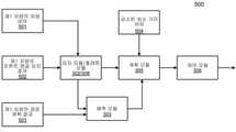
도 5는 본 발명의 실시형태와 함께 사용되는 다양한 모듈을 나타내는 블록도이다.
도 6은 일 실시형태에 따른 플래툰 처리의 과정을 나타내는 예시적 흐름도이다.
도 7은 일 실시형태에 따른 2대의 자율 주행 차량 사이에서 군집 주행을 구현하는 예시적 방법을 나타내는 흐름도이다.BRIEF DESCRIPTION OF THE DRAWINGS An embodiment of the present invention is shown in each figure in the accompanying drawings by way of example and not limitation, in which like reference numerals designate like elements.
1 is a block diagram illustrating a networked system according to an embodiment.
2 is a block diagram illustrating an example of an autonomous driving vehicle according to an embodiment.
3A-3B are block diagrams illustrating examples of sensing and planning systems used with autonomous vehicles in accordance with one embodiment.
4 is a block diagram illustrating an exemplary environment for implementing an embodiment of the present invention.
5 is a block diagram illustrating various modules used with an embodiment of the present invention.
6 is an exemplary flowchart illustrating a process of platoon processing according to an embodiment.
7 is a flowchart illustrating an example method of implementing platooning between two autonomous driving vehicles according to an embodiment.
아래에 기술되는 상세한 내용을 참조하여 본 발명의 다양한 실시형태 및 양태를 설명하며, 도면에서 상기 다양한 실시형태를 도시하였다. 아래 설명과 첨부된 도면은 본 발명에 대한 설명일 뿐, 본 발명을 한정하는 것으로 해석되어서는 안된다. 본 발명의 다양한 실시형태에 대한 전면적인 이해를 제공하기 위해 많은 특정된 세부 내용을 설명하였다. 그러나 일부 경우, 본 발명의 실시형태에 대해 간결하게 논의하기 위해, 이미 잘 알려진 또는 통상적인 세부 사항에 대해 설명하지 않는다.DETAILED DESCRIPTION OF THE PREFERRED EMBODIMENTS Various embodiments and aspects of the present invention will now be described with reference to the detailed description set forth below, in which drawings the various embodiments are illustrated. The following description and the accompanying drawings are only descriptions of the present invention, and should not be construed as limiting the present invention. Numerous specific details have been set forth in order to provide a thorough understanding of various embodiments of the invention. However, in some instances, well-known or common details are not set forth in order to concisely discuss embodiments of the present invention.
본 명세서에서 “일 실시형태” 또는 “실시형태”에 대한 언급은 상기 실시형태를 참조하여 설명한 특정된 특징, 구조 또는 특성이 본 발명의 적어도 일 실시형태에 포함될 수 있다는 것을 의미한다. 본 명세서 각각에 기재된 단어 “일 실시형태에서”는 반드시 전부 동일한 실시형태를 가리켜야 하는 것은 아니다.Reference in this specification to “one embodiment” or “an embodiment” means that a specified feature, structure, or characteristic described with reference to the embodiment may be included in at least one embodiment of the present invention. The words “in one embodiment” in each of the references in this specification are not necessarily all referring to the same embodiment.
본 발명의 실시형태는 2대의 자율 주행 차량 사이에서 군집 주행을 구현하는 방법, 장치 및 시스템에 관한 것이다. 일 실시형태에 따르면, 제2 ADV에서, 차량 대 차량(V2V, Vehicle-to-Vehicle) 링크를 통해 제1 ADV로부터 차량 상태 및 제1 감지 결과를 수신한다. 제1 감지 결과는 제1 ADV에 의해 감지된 하나 또는 복수의 장애물을 포함한다. 제2 ADV는 제2 ADV와 연관되는 주행 환경을 감지하도록 감지 과정을 수행하여 제2 감지 결과를 생성한다. 제1 ADV에 의해 수행된 제1 감지 결과와 제2 ADV에 의해 수행된 제2 감지 결과를 병합하여 제3 감지 결과를 생성한다. 제1 ADV의 차량 상태 및 제3 감지 결과에 기반하여 궤적을 계획하여, 제2 ADV가 플래툰 방식으로 제1 ADV를 뒤따르도록 한다.Embodiments of the present invention relate to methods, apparatus and systems for implementing platooning between two autonomous vehicles. According to an embodiment, in the second ADV, the vehicle state and the first detection result are received from the first ADV through a vehicle-to-vehicle (V2V) link. The first detection result includes one or more obstacles detected by the first ADV. The second ADV generates a second detection result by performing a sensing process to sense a driving environment associated with the second ADV. A third detection result is generated by merging the first detection result performed by the first ADV and the second detection result performed by the second ADV. A trajectory is planned based on the vehicle status of the first ADV and the third detection result, so that the second ADV follows the first ADV in a platoon manner.
실시형태에 따르면, 또한, V2V 링크를 통해 제1 ADV로부터 제1 ADV에 의해 수행된 경로 계획 결과를 수신한다. 경로 계획 결과는 제1 ADV에 의해 계획된 궤적을 포함한다. 제1 ADV의 경로 계획 결과에 기반하여 제1 ADV의 운동을 예측한다. 예측에 기반하여 제1 ADV의 예측 궤적을 생성한다. 예측 궤적은 제2 ADV에 의해 예측된 제1 ADV의 궤적을 나타낸다. 제1 감지 결과는 제1 ADV의 정면뷰로부터 감지된 프론트 앵글 감지를 나타낸다.According to the embodiment, further, a route planning result performed by the first ADV is received from the first ADV via the V2V link. The route planning result includes the trajectory planned by the first ADV. The motion of the first ADV is predicted based on the path planning result of the first ADV. A prediction trajectory of the first ADV is generated based on the prediction. The prediction trajectory indicates the trajectory of the first ADV predicted by the second ADV. The first detection result indicates detection of the front angle detected from the front view of the first ADV.
일 실시형태에서, 제1 감지 결과와 제2 감지 결과를 병합할 경우, 수신된 차량 상태를 이용하여 제2 ADV의 제2 감지 결과 중 제1 ADV를 감지하는 감지 데이터를 대체한다. 제1 ADV와 제2 ADV 사이에서 최소 거리 버퍼를 기설정된 플래툰 거리까지 감소시킨다. 제1 ADV의 차량 상태는 전역 좌표계에서의 제1 ADV의 위치, 제1 ADV의 속도 및/또는 제1 ADV의 전진 방향을 포함한다. 제2 ADV와 장애물 사이의 최소 거리 버퍼가 상대적으로 변하지 않도록 유지한다.In one embodiment, when the first detection result and the second detection result are merged, the sensed data for detecting the first ADV among the second detection results of the second ADV is replaced by using the received vehicle state. The minimum distance buffer between the first ADV and the second ADV is reduced to a preset platoon distance. The vehicle state of the first ADV includes a position of the first ADV in the global coordinate system, a velocity of the first ADV and/or a forward direction of the first ADV. Keep the minimum distance buffer between the second ADV and the obstacle relatively unchanged.
일 실시형태에서, 제2 ADV를 뒤따르는 제3 ADV가 존재할 경우, 제2 ADV의 차량 상태, 감지 결과 및/또는 계획 정보는 V2V 링크를 통해 제2 ADV로부터 제3 ADV로 전송됨으로써, 제3 ADV가 플래툰 방식으로 제2 ADV를 계획하고 뒤따르도록 한다.In one embodiment, when there is a third ADV following the second ADV, the vehicle status, sensing result and/or planning information of the second ADV is transmitted from the second ADV to the third ADV via the V2V link, whereby the third ADV Let the ADV plan and follow the second ADV in a platoon fashion.
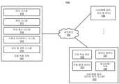
도 1은 본 발명의 일 실시형태에 따른 자율 주행 차량의 네트워크 구성을 나타내는 블록도이다. 도 1을 참조하면, 네트워크 구성(100)은 네트워크(102)에 의해 하나 또는 복수의 서버(103 내지 104)에 통신 가능하게 연결될 수 있는 자율 주행 차량(101)을 포함한다. 비록 하나의 자율 주행 차량을 도시하였지만 복수의 자율 주행 차량은 네트워크(102)에 의해 서로 연결될 수 있고 및/또는 서버(103 내지 104)에 연결될 수 있다. 네트워크(102)는 유선 또는 무선의 근거리 통신망(LAN), 인터넷과 같은 광역 네트워크(WAN), 셀룰러 네트워크, 위성 네트워크 또는 이들의 조합과 같은 임의의 유형의 네트워크일 수 있다. 서버(103 내지 104)는 웹(Web) 또는 클라우드 서버, 애플리케이션 서버, 백엔드 서버 또는 이들의 조합과 같은 임의의 유형의 서버 또는 서버 클러스터일 수 있다. 서버(103 내지 104)는 데이터 분석 서버, 컨텐츠 서버, 교통 정보 서버, 지도 및 관심지점(MPOI) 서버 또는 위치 서버 등일 수 있다.1 is a block diagram illustrating a network configuration of an autonomous vehicle according to an embodiment of the present invention. Referring to FIG. 1 , a
자율 주행 차량은 자율 주행 모드로 설정될 수 있는 차량을 가리키며, 상기 자율 주행 모드에서, 차량은 운전자로부터 입력이 거의 없거나 전혀없는 상황에서 내비게이트하여 환경을 통과한다. 이러한 자율 주행 차량은 차량 작동 환경과 관련되는 정보를 검출하도록 구성된 하나 또는 복수의 센서를 갖는 센서 시스템을 포함할 수 있다. 상기 차량 및 이와 관련된 컨트롤러는 검출된 정보를 사용하여 내비게이트하여 상기 환경을 통과한다. 자율 주행 차량(101)은 수동 모드, 완전 자율 모드 또는 부분 자율 모드에서 작동할 수 있다.An autonomous vehicle refers to a vehicle that can be set to an autonomous driving mode, in which the vehicle navigates through the environment with little or no input from the driver. Such autonomous vehicles may include a sensor system having one or more sensors configured to detect information related to the vehicle operating environment. The vehicle and its associated controller use the detected information to navigate through the environment. The autonomous vehicle 101 may operate in a manual mode, a fully autonomous mode or a partially autonomous mode.
일 실시형태에서, 자율 주행 차량(101)은 감지 및 계획 시스템(110), 차량 제어 시스템(111), 무선 통신 시스템(112), 사용자 인터페이스 시스템(113), 정보 오락 시스템(미도시) 및 센서 시스템(115)을 포함하나 이에 한정되지 않는다. 자율 주행 차량(101)은 일반 차량에 포함되는 엔진, 휠, 핸들, 변속기 등과 같은 일부 흔히 사용되는 구성 요소들을 더 포함할 수 있으며, 상기 구성 요소는 차량 제어 시스템(111) 및/또는 감지 및 계획 시스템(110)에 의해 가속 신호 또는 명령, 감속 신호 또는 명령, 스티어링 신호 또는 명령, 브레이킹 신호 또는 명령 등과 같은 다양한 통신 신호 및/또는 명령에 의해 제어될 수 있다.In one embodiment, autonomous vehicle 101 includes sensing and
구성 요소(110) 내지 구성 요소(115)는 인터커넥트, 버스, 네트워크 또는 이들의 조합에 의해 상호 통신 가능하게 연결될 수 있다. 예를 들어, 구성 요소(110) 내지 구성 요소(115)는 컨트롤러 영역 네트워크(CAN) 버스를 통하여 상호 통신 가능하게 연결될 수 있다. CAN 버스는 마이크로컨트롤러 및 장치가 호스트가 없는 응용환경에서 서로 통신할 수 있도록 설계된 차량 버스 표준이다. 이는 최초에 자동차 내부의 다중 전기 배선을 위해 설계된 메시지 기반 프로토콜이지만, 기타 다양한 환경에도 사용된다.The
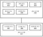
도 2를 참조하면, 일 실시형태에서, 센서 시스템(115)은 하나 또는 복수의 카메라(211), 글로벌 포지셔닝 시스템(GPS) 유닛(212), 관성 측정 유닛(IMU; 213), 레이더 유닛(214) 및 광 검출 및 거리 측정(LIDAR) 유닛(215)을 포함하나 이에 한정되지 않는다. GPS 유닛(212)은 자율 주행 차량의 위치에 관한 정보를 제공하도록 작동될 수 있는 트랜시버를 포함할 수 있다. IMU 유닛(213)은 관성 가속도에 기반하여 자율 주행 차량의 위치 및 방향의 변화를 감지할 수 있다. 레이더 유닛(214)은 무선 전기 신호를 이용하여 자율 주행 차량의 로컬 환경 내의 객체를 감지하는 시스템을 나타낼 수 있다. 일부 실시형태에서, 객체를 감지하는 것 외에, 레이더 유닛(214)은 객체의 속도 및/또는 전진 방향을 별도로 감지할 수 있다. LIDAR 유닛(215)은 레이저를 사용하여 자율 주행 차량이 위치한 환경 중의 객체를 감지할 수 있다. 기타 시스템 구성 요소 외에도, LIDAR 유닛(215)은 하나 또는 복수의 레이저 소스, 레이저 스캐너 및 하나 또는 복수의 검출기를 더 포함할 수 있다. 카메라(211)는 자율 주행 차량 주변 환경의 이미지를 수집하는 하나 또는 복수의 장치를 포함할 수 있다. 카메라(211)는 스틸 카메라 및/또는 비디오 카메라일 수 있다. 카메라는 예를 들어 카메라를 회전 및/또는 경사진 플랫폼에 장착함으로써 기계적으로 움직일 수 있다.2 , in one embodiment, the
센서 시스템(115)은 소나(sonar) 센서, 적외선 센서, 스티어링(steering) 센서, 스로틀(throttle) 센서, 브레이킹 센서 및 오디오 센서(예를 들어, 마이크로폰)와 같은 기타 센서들을 더 포함할 수 있다. 오디오 센서는 자율 주행 차량 주변의 환경으로부터 소리를 수집하도록 구성될 수 있다. 스티어링 센서는 핸들, 차량의 휠 또는 이들의 조합의 스티어링 각도를 감지하도록 구성될 수 있다. 스로틀 센서 및 브레이킹 센서는 각각 차량의 스로틀 위치 및 브레이킹 위치를 감지한다. 일부 상황에서, 스로틀 센서 및 브레이킹 센서는 통합식 스로틀/브레이킹 센서로 통합될 수 있다.The
일 실시형태에서, 차량 제어 시스템(111)은 스티어링 유닛(201), 스로틀 유닛(202)(가속 유닛으로 지칭되기도 함) 및 브레이킹 유닛(203)을 포함하나 이에 한정되지 않는다. 스티어링 유닛(201)은 차량의 방향 또는 전진 방향을 조정하기 위한 것이다. 스로틀 유닛(202)은 모터 또는 엔진의 속도를 제어하며 나아가 차량의 속도 및 가속도를 제어하기 위한 것이다. 브레이킹 유닛(203)은 마찰을 제공함으로써 차량의 휠 또는 타이어를 감속시키고 나아가 차량을 감속시킨다. 도 2에 도시된 구성 요소는 하드웨어, 소프트웨어 또는 이들의 조합으로 구현될 수 있음을 유의해야 한다.In one embodiment, the
도 1을 다시 참조하면, 무선 통신 시스템(112)은 자율 주행 차량(101)과 장치, 센서, 기타 차량 등과 같은 외부 시스템 사이의 통신을 허용한다. 예를 들어, 무선 통신 시스템(112)은 하나 또는 복수의 장치와 직접 무선 통신될 수 있거나 통신 네트워크를 경유하여 무선 통신될 수 있는 바, 예를 들어, 네트워크(102)에 의해 서버(103 내지 104)와 통신된다. 무선 통신 시스템(112)은 임의의 셀룰러 통신 네트워크 또는 무선 근거리 통신망(WLAN)을 사용할 수 있으며, 예를 들어 WiFi를 사용하여 다른 일 구성 요소 또는 시스템과 통신한다. 무선 통신 시스템(112)은 예를 들어 적외선 링크, 블루투스 등을 사용하여 장치(예를 들어, 승객의 모바일 장치, 디스플레이 장치, 차량(101) 내의 스피커)와 직접 통신할 수 있다. 사용자 인터페이스 시스템(113)은 차량(101) 내에 구현된 주변 장치의 일부분일 수 있으며, 예를 들어 키보드, 터치 스크린 디스플레이 장치, 마이크로폰 및 스피커 등을 포함한다.Referring back to FIG. 1 , the wireless communication system 112 allows for communication between the autonomous vehicle 101 and external systems such as devices, sensors, other vehicles, and the like. For example, the wireless communication system 112 may be in direct wireless communication with one or a plurality of devices or may be in wireless communication via a communication network, eg, by the
자율 주행 차량(101)의 일부 또는 모든 기능은 특히 자율 주행 모드에서 작동할 때 감지 및 계획 시스템(110)에 의해 제어 또는 관리될 수 있다. 감지 및 계획 시스템(110)은 센서 시스템(115), 제어 시스템(111), 무선 통신 시스템(112) 및/또는 사용자 인터페이스 시스템(113)으로부터 정보를 수신하고, 수신된 정보를 처리하며, 출발점으로부터 목적지까지의 루트 또는 경로를 계획하고, 이어서 계획 및 제어 정보에 의해 차량(101)을 주행하기 위해 필요한 하드웨어(예를 들어, 프로세서, 메모리, 저장 기기) 및 소프트웨어(예를 들어, 운영 체제, 계획 및 경로 배정 프로그램)를 포함한다. 대안적으로, 감지 및 계획 시스템(110)은 차량 제어 시스템(111)과 통합될 수 있다.Some or all functions of the autonomous vehicle 101 may be controlled or managed by the sensing and
예를 들어, 사용자는 승객으로서 예를 들어 사용자 인터페이스를 통해 코스의 시작 위치 및 목적지를 지정할 수 있다. 감지 및 계획 시스템(110)은 코스 관련 데이터를 획득한다. 예를 들어, 감지 및 계획 시스템(110)은 MPOI 서버로부터 위치 및 루트 정보를 획득할 수 있고, 상기 MPOI 서버는 서버(103 내지 104)의 일부분일 수 있다. 위치 서버는 위치 서비스를 제공하며, MPOI 서버는 지도 서비스 및 특정된 위치의 POI를 제공한다. 대안적으로, 이러한 위치 및 MPOI 정보는 감지 및 계획 시스템(110)의 영구 저장 장치에 로컬로 캐싱될 수 있다.For example, a user may, as a passenger, designate a starting location and destination of a course, for example via a user interface. The sensing and
자율 주행 차량(101)이 루트를 따라 이동할 경우, 감지 및 계획 시스템(110)은 교통 정보 시스템 또는 서버(TIS)로부터 실시간 교통 정보를 획득할 수도 있다. 서버(103 내지 104)는 제3 엔티티에 의해 작동될 수 있음을 유의해야 한다. 대안적으로, 서버(103 내지 104)의 기능은 감지 및 계획 시스템(110)과 통합될 수 있다. 실시간 교통 정보, MPOI 정보 및 위치 정보 및 센서 시스템(115)에 의해 검출 또는 감지된 실시간 로컬 환경 데이터(예를 들어, 장애물, 객체, 주변 차량)에 기반하여, 감지 및 계획 시스템(110)은 최적 루트를 계획하고 계획한 루트에 따라, 예를 들어 제어 시스템(111)을 경유하여 차량(101)을 운전하여 지정된 목적지에 안전하고 효율적으로 도착할 수 있다.When the autonomous vehicle 101 moves along a route, the detection and
서버(103)는 다양한 클라이언트를 위해 데이터 분석 서비스를 수행하는 데이터 분석 시스템일 수 있다. 데이터 분석 시스템(103)은 데이터 컬렉터(121) 및 기계 학습 엔진(122)을 포함한다. 데이터 컬렉터(121)는 다양한 차량(자율 주행 차량 또는 인간 운전자가 운전하는 일반 차량임)으로부터 주행 카운팅 데이터(123)를 수집한다. 주행 카운팅 데이터(123)는 상이한 시점에서 송달된 운전 명령(예를 들어, 스로틀 명령, 브레이킹 명령, 스티어링 명령) 및 차량의 센서에 의해 포착된 차량의 응답(예를 들어, 속도, 가속, 감속, 방향)을 나타내는 정보를 포함한다. 주행 카운팅 데이터(123)는 예를 들어, 루트(시작 위치 및 목적지 위치를 포함함), MPOI, 도로 상황, 기상 조건 등과 같은 상이한 시점에서의 운전 환경을 설명하는 정보를 더 포함할 수 있다.The
주행 카운팅 데이터(123)에 기반하여, 기계 학습 엔진(122)은 다양한 목적으로 일련의 규칙, 알고리즘 및/또는 예측 모델(124)을 생성하거나 트레이닝한다. 일 실현형태에 있어서, 알고리즘(124)은 자율 주행 차량(101)이 플래툰 모드에서 동작할 수 있도록 하는 방법을 포함할 수 있다.Based on the driving counting data 123 , the machine learning engine 122 generates or trains a set of rules, algorithms and/or
이어서 알고리즘(124)을 ADV에 업로딩함으로써 자율 주행 과정 기간에 실시간으로 이용할 수 있다.The
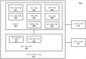
도 3a 및 도 3b는 일 실시형태에 따른 자율 주행 차량과 함께 사용되는 감지 및 계획 시스템의 예시를 나타내는 블록도이다. 시스템(300)은 도 1의 자율 주행 차량(101)의 일부분으로 구현될 수 있으며, 감지 및 계획 시스템(110), 제어 시스템(111) 및 센서 시스템(115)을 포함하나 이에 한정되지 않는다. 도 3a 내지 도 3b를 참조하면, 감지 및 계획 시스템(110)은 위치결정 모듈(301), 감지 모듈(302), 예측 모듈(303), 의사결정 모듈(304), 계획 모듈(305), 제어 모듈(306), 경로배정 모듈(307) 및 플래툰 모듈(308)을 포함하나 이에 한정되지 않는다.3A and 3B are block diagrams illustrating examples of sensing and planning systems used with autonomous vehicles in accordance with one embodiment.
모듈(301) 내지 모듈(308) 중의 일부 또는 전부는 소프트웨어, 하드웨어 또는 이들의 조합에 의해 구현될 수 있다. 예를 들어, 이러한 모듈은 영구 저장 장치(352)에 실장되고, 메모리(351)에 로딩되며, 하나 또는 복수의 프로세서(미도시)에 의해 수행될 수 있다. 유의해야 할 것은, 이러한 모듈 중의 일부 또는 전부는 도 2의 차량 제어 시스템(111)의 일부 또는 전부 모듈에 통신 가능하게 연결될 수 있거나 이들과 통합될 수 있다. 모듈(301) 내지 모듈(308) 중의 일부는 집적 모듈로 함께 통합될 수 있다.Some or all of the modules 301 to 308 may be implemented by software, hardware, or a combination thereof. For example, such a module may be mounted in the
위치결정 모듈(301)(예를 들어, GPS 유닛(212)을 이용함)은 자율 주행시스템(300)의 현재 위치를 결정하여 사용자의 코스 또는 루트와 관련된 임의의 데이터를 관리한다. 위치결정 모듈(301)(지도 및 루트 모듈로 지칭되기도 함)은 사용자의 코스 또는 루트와 관련된 임의의 데이터를 관리한다. 사용자는 예를 들어 사용자 인터페이스를 통해 로그인하여 코스의 시작 위치 및 목적지를 지정할 수 있다. 위치결정 모듈(301)은 코스 관련 데이터를 얻기 위해 지도 및 루트 정보(311)와 같은 자율 주행 시스템(300)의 기타 구성 요소들과 통신한다. 예를 들어, 위치결정 모듈(301)은 위치 서버 및 지도 및 POI(MPOI) 서버로부터 위치 및 루트 정보를 획득할 수 있다. 위치 서버는 위치 서비스를 제공하고, MPOI 서버는 지도 서비스 및 특정된 위치의 POI를 제공하며, 이러한 서비스 및 POI는 지도 및 루트 정보(311)의 일부분으로서 캐싱될 수 있다. 자율 주행 시스템(300)이 루트를 따라 이동할 경우, 위치결정 모듈(301)은 또한 교통 정보 시스템 또는 서버로부터 실시간 교통 정보를 획득할 수 있다.The positioning module 301 (eg, using the GPS unit 212) determines the current location of the
센서 시스템(115)에 의해 제공된 센서 데이터 및 위치결정 모듈(301)에 의해 획득된 위치결정 정보에 기반하여, 감지 모듈(302)은 주변 환경에 대한 감지를 결정한다. 감지 정보는 운전자가 운전하고 있는 차량 주위에서 일반 운전자가 감지하는 물체를 나타낼 수 있다. 감지는 예를 들어, 객체 형태의 차선 구성, 신호등 신호, 기타 차량의 상대 위치, 보행자, 건축물, 횡단 보도 또는 기타 교통 관련 표지(예를 들어, 정지 표지, 양보운전 표지) 등을 포함할 수 있다. 차선 구성은 차선의 형상(예를 들어, 직선 또는 곡률), 차선의 폭, 도로 중의 차선 수, 단방향 또는 양방향 차선, 합류 차선 또는 분류 차선, 출구 차선 등과 같은 하나의 차선 또는 복수의 차선을 설명하는 정보를 포함한다.Based on the sensor data provided by the
감지 모듈(302)은 하나 또는 복수의 카메라에 의해 포착된 이미지를 처리하고 분석함으로써 자율 주행 차량 환경에서 객체 및/또는 특징을 식별하는 컴퓨터 시각 시스템 또는 컴퓨터 시각 시스템의 기능을 포함할 수 있다. 상기 객체는 교통 신호, 도로 경계, 기타 차량, 보행자 및/또는 장애물 등을 포함할 수 있다. 컴퓨터 시각 시스템은 객체 식별 알고리즘, 비디오 추적 및 기타 컴퓨터 시각 기술을 사용할 수 있다. 일부 실시형태에서, 컴퓨터 시각 시스템은 환경 지도를 제작하고, 객체를 추적하며, 객체의 속도를 추정할 수 있다. 감지 모듈(302)은 또한 레이더 및/또는 LIDAR와 같은 기타 센서에 의해 제공된 기타 센서 데이터에 기반하여 객체를 검출할 수 있다.The
각각의 객체에 대해, 예측 모듈(303)은 상기 경우에서 상기 객체의 행위를 예측한다. 상기 예측은 특정 시점에서 감지된 주행 환경의 감지 데이터에 기반하여 지도/루트 정보(311)와 교통 규칙(312)의 집합에 따라 수행된다. 예를 들어, 객체가 반대 방향에 있는 차량이고 현재 주행 환경이 교차로를 포함할 경우, 예측 모듈(303)은 상기 차량이 직진할 것인지 아니면 회전할 것인지를 예측한다. 감지 데이터가 교차로에 신호등이 없음을 나타낼 경우, 예측 모듈(303)은 상기 차량이 교차로에 진입하기 전에 완전히 정지해야 함을 예측할 수 있다. 감지 데이터가 상기 차량이 현재 좌회전 전용 차선 또는 우회전 전용 차선에 있음을 나타낼 경우, 예측 모듈(303)은 각 경우에 상기 차량이 좌회전 또는 우회전 할 가능성이 더 높다고 예측할 수 있다.For each object, the
각각의 객체에 대해, 의사결정 모듈(304)은 객체를 어떻게 처리할 것인지에 관해 결정한다. 예를 들어, 특정 객체(예를 들어, 교차 노선 중의 다른 하나의 차량) 및 객체를 표현한 메타데이터(예를 들어, 속도, 방향, 회전 각도)에 대해, 의사결정 모듈(304)은 상기 객체와 어떻게 마주(예를 들어, 추월, 양보, 정지, 경과)할 것인 지에 대해 결정한다. 의사결정 모듈(304)은 교통 규칙 또는 운전 규칙(312)과 같은 규칙 세트에 따라 해당 결정을 내릴 수 있으며, 상기 규칙 세트는 영구 저장 장치(352)에 저장될 수 있다.For each object, the decision module 304 determines how to process the object. For example, for a particular object (e.g., a vehicle on another one of the intersections) and metadata representing the object (e.g., speed, direction, angle of rotation), the decision module 304 may Decide how to face (eg, overtake, yield, stop, pass). The decision-making module 304 may make a corresponding decision according to a set of rules, such as traffic rules or driving
경로배정 모듈(307)은 출발점으로부터 종점까지의 하나 또는 복수의 루트 또는 경로를 제공하도록 구성된다. 예를 들어, 사용자로부터 수신된 시작 위치로부터 목적지 위치까지의 주어진 코스에 대해, 경로배정 모듈(307)은 지도 및 루트 정보(311)를 획득하여 시작 위치로부터 목적지 위치에 도착할 수 있는 모든 가능한 루트 또는 경로를 결정한다. 경로배정 모듈(307)은 상기 결정한 시작 위치로부터 목적지 위치에 도착할 수 있는 루트 중의 각각에 대해 지형도의 형태로 기준 노선을 생성할 수 있다. 기준 노선은 기타 차량, 장애물 또는 교통 상황과 같은 임의의 간섭을 받지 않는 이상적인 루트 또는 이상적인 경로를 나타낸다. 즉, 도로에 기타 차량, 보행자 또는 장애물이 없을 경우, ADV는 기준 노선을 정확하게 또는 근접되게 준수해야 한다. 이어서, 의사결정 모듈(304) 및/또는 계획 모듈(305)에 지형도를 제공할 수 있다. 기타 모듈에 의해 제공된 기타 데이터(예를 들어, 위치결정 모듈(301)로부터의 교통 상황, 감지 모듈(302)에 의해 감지된 주행 환경 및 예측 모듈(303)에 의해 예측된 교통 상황)에 따라, 의사결정 모듈(304) 및/또는 계획 모듈(305)은 모든 가능한 루트를 검증하여 그중 하나의 최적 루트를 선택하고 수정한다. 특정된 시점에서의 특정된 주행 환경에 의하여, ADV를 제어하는 실제 경로 또는 루트는 경로배정 모듈(307)에 의해 제공된 기준 노선에 근접할 수 있거나 상이할 수 있다.The routing module 307 is configured to provide one or a plurality of routes or routes from a starting point to an ending point. For example, for a given course from a starting location to a destination location received from the user, the routing module 307 obtains the map and
감지된 객체 중의 각각에 대한 결정에 기반하여, 계획 모듈(305)은 경로배정 모듈(307)이 제공한 기준 노선을 기준으로 사용하며, 자율 주행 차량을 위해 경로 또는 루트 및 주행 파라미터(예를 들어, 거리, 속도 및/또는 회전 각도)를 계획한다. 즉, 주어진 객체에 대해, 의사결정 모듈(304)은 객체에 대해 어떤 동작을 수행할 것인지를 결정하고, 계획 모듈(305)은 어떻게 수행할 것인지를 결정한다. 예를 들어, 주어진 객체에 대해, 의사결정 모듈(304)은 상기 객체를 경과할 것으로 결정할 수 있고, 계획 모듈(305)은 상기 객체의 좌측에서 경과할 것인지 아니면 우측에서 경과할 것인지를 결정할 수 있다. 계획 및 제어 데이터는 계획 모듈(305)에 의해 생성되며, 시스템(300)을 포함하는 차량이 다음 이동 주기(예를 들어, 다음 루트/경로 구간)에서 어떻게 이동할 것인지를 설명하는 정보를 포함한다. 예를 들어, 계획 및 제어 데이터는 시스템(300)을 포함하는 차량이 시간 당 30 마일(mph)의 속도로 10 미터를 이동한 다음 25 mph의 속도로 우측 차선으로 변경하도록 지시할 수 있다.Based on the determination of each of the detected objects, the
계획 및 제어 데이터에 기반하여, 제어 모듈(306)은 계획 및 제어 데이터에 의해 한정된 루트 또는 경로에 따라 적절한 명령 또는 신호를 차량 제어 시스템(111)에 발송함으로써 자율 주행 차량을 제어 및 주행한다. 상기 계획 및 제어 데이터는 경로 또는 루트를 따라 상이한 시간점에서 적절한 차량 설정 또는 운전 파라미터(예를 들어, 스로틀, 브레이킹 및 스티어링 명령)를 사용하여 차량을 루트 또는 경로의 제1 지점으로부터 제2 지점으로 주행시키기에 충분한 정보를 포함한다.Based on the planning and control data, the
일 실시형태에서, 계획 단계는 복수의 계획 주기(주행 주기라고 지칭되기도 함)로 수행되는 바, 예를 들어, 100 밀리초(ms)의 시간 간격으로 수행된다. 각각의 계획 주기 또는 주행 주기에 대해, 계획 및 제어 데이터에 기반하여 하나 또는 복수의 제어 명령을 발송할 것이다. 즉 각각의 100 ms에 대해, 계획 모듈(305)은 다음 루트 구간 또는 경로 구간을 계획하며, 예를 들어, 목적 위치 및 ADV가 상기 목적 위치에 도착하는데 필요한 시간을 포함한다. 대안적으로, 계획 모듈(305)은 또한 구체적인 속도, 방향 및/또는 스티어링 각도 등을 지정할 수 있다. 일 실시형태에서, 계획 모듈(305)은 다음 기설정된 시간대(예를 들어, 5초)의 루트 구간 또는 경로 구간을 계획한다. 각각의 계획 주기에 대해, 계획 모듈(305)은 이전 주기에서 계획한 목적 위치에 기반하여 현재 주기(예를 들어, 다음번 5초)에 대한 목적 위치를 계획한다. 이어서, 제어 모듈(306)은 현재 주기의 계획 및 제어 데이터에 기반하여 하나 또는 복수의 제어 명령(예를 들어, 스로틀 제어 명령, 브레이킹 제어 명령, 스티어링 제어 명령)을 생성한다.In one embodiment, the planning phase is performed in a plurality of planning cycles (also referred to as driving cycles), eg, with a time interval of 100 milliseconds (ms). For each planning cycle or driving cycle, one or a plurality of control commands may be sent based on the planning and control data. That is, for each 100 ms, the
의사결정 모듈(304) 및 계획 모듈(305)은 집적 모듈로 통합될 수 있음을 유의해야 한다. 의사결정 모듈(304)/계획 모듈(305)은 자율 주행 차량의 주행 경로를 결정하기 위해 항법 시스템 또는 항법 시스템의 기능을 포함할 수 있다. 예를 들어, 항법 시스템은 자율 주행 차량이 하기와 같은 경로를 따라 이동되는 일련의 속도 및 전진 방향을 결정할 수 있다. 즉 상기 경로는 자율 주행 차량이 최종 목적지로 향하는 차선-기반 경로를 따라 전진하는 동시에 감지된 장애물을 실질적으로 피하도록 한다. 목적지는 사용자 인터페이스 시스템(113)을 통해 입력된 사용자 입력에 따라 설정될 수 있다. 항법 시스템은 자율 주행 차량이 작동하고 있는 동시에 주행 경로를 동적으로 업데이트할 수 있다. 항법 시스템은 GPS 시스템 및 하나 또는 복수의 지도에 의해 획득된 데이터를 병합하여 자율 주행 차량을 위한 주행 경로를 결정할 수 있다.It should be noted that the decision-making module 304 and the
일 실시형태에 따르면, 플래툰 모듈(308)은 플래툰 처리를 실행하도록 구성됨으로써, ADV가 플래툰 방식으로 다른 차량을 뒤따르도록 한다. 플래툰 모듈(308)은 감지 모듈(302)의 일부분으로 구현될 수 있다. 선택 가능하게, 플래툰 모듈(308)은 감지 모듈(302), 예측 모듈(303) 및 계획 모듈(305)에 통신적으로 연결되는 별도의 모듈일 수 있다. 플래툰 모듈(308)은 안내 차량으로부터의 감지, 예측 및 계획 정보의 적어도 일부분을 수신 및 이용하여 그 자체의 감지, 예측 및 계획 정보를 결합함으로써 ADV(101)가 플래툰 방식으로 안내 차량을 뒤따르도록 계획할 수 있다.According to one embodiment, the platoon module 308 is configured to perform platoon processing, such that the ADV follows other vehicles in a platoon manner. The platoon module 308 may be implemented as part of the
도 4를 참조하면, 본 발명의 실시형태를 구현할 수 있는 예시적 환경(400)의 블록도를 나타낸다. 일부 자율 주행 차량은 도로(430)에서 플래툰 방식으로 주행한다. 행진 방향에서, 제1 차량(410)은 안내 차량이고, 제2 차량(420)은 제1 차량의 바로 뒤에 위치하는 뒤따르는 차량이다. 플래툰은 제2 차량(420) 뒤에 하나 또는 복수의 부가적으로 뒤따르는 차량을 포함할 수 있다. 제1 차량(410)은 차량 대 차량의 데이터 링크를 통해 제2 차량(420)에 1) 전역 좌표계에서의 제1 차량(410)의 현재 차량 상태 (위치, 속도, 전진 방향 중 하나 또는 복수 또는 이들의 조합을 포함할 수 있음); 2) 프론트 앵글 감지 결과(즉, 제1 차량(410) 앞의 물체에 대한 감지); 및 3) 제1 차량(410)의 자율 주행 경로 계획 결과를 전송할 수 있다.4, there is shown a block diagram of an
제2 차량(420)에 제1 차량(410)의 프론트 앵글 감지 결과를 제공함으로써 제2 차량(420)의 감지를 개선할 수 있는데, 이는 제2 차량(420)이 제1 차량(410)을 효과적으로 “간파(see through)”할 수 있도록 하기 때문이다. 일 실시형태에서, 제1 차량(410)은 통신 메시지 크기를 감소시키기 위해, 프론트 앵글 감지와 관련된 원래의 포인트 클라우드 또는 이미지 입력을 송신하지 않을 수도 있다. 반대로, 제1 차량(410)은 감지 과정의 결과만 송신하고, 감지 과정의 결과는 적어도 제1 차량(410)의 감지 모듈에 의해 검출된 하나 또는 복수의 장애물을 설명하는 정보를 포함한다. 예를 들어, 감지 결과는 검출된 각각의 장애물의 위치(x, y), 속도 및 전진 방향을 포함할 수 있다. 정지 상태 장애물에 대해, 속도 및 전진 방향은 0일 수 있고, 이는 정지 상태 물체에 대한 지시로 사용될 수 잇다. 제1 차량(410)은 상술한 자율 주행 기능을 포함할 수 있고, 도 3a 내지 도 3b에 도시된 자율 주행 모듈 중의 적어도 일부를 포함할 수 있다.The detection of the
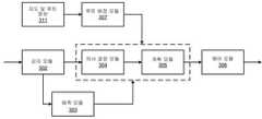
도 5를 참조하면, 본 발명의 실시형태와 함께 사용되는 다양한 모듈의 블록도(500)을 나타낸다. 제2 차량은 제1 차량으로부터 제1 차량의 차량 상태(501), 제1 차량의 프론트 앵글 감지 결과(502) 및 제1 차량의 경로 계획 결과(503)를 수신한다. 제1 차량의 차량 상태(501) 및 제1 차량의 프론트 앵글 감지 결과(502)는 제2 차량의 감지 모듈(302)에 전달된다. 본 예시에서, 플래툰 모듈(308)은 감지 모듈(302)의 일부분으로 구현된다. 여기서, 제1 차량의 프론트 앵글 감지 결과(502)와 제2 차량의 감지 결과를 병합하고, 수신된 제1 차량의 차량 상태(501)를 제2 차량의 감지 결과에서의 인식 객체 리스트 중 제1 차량과 연관되는 감지 데이터로 대체한다.5, a block diagram 500 of various modules used with an embodiment of the present invention is shown. The second vehicle receives the
제1 차량의 경로 계획 결과(503)는 제2 차량의 예측 모듈(303)에 전달되고, 여기서, 적어도 부분적으로 제1 차량의 경로 계획 결과(503)에 기반하여 제1 차량의 궤적을 예측한다. 제1 차량의 궤적을 예측할 시, 제1 차량으로부터 수신된 각각의 궤적 포인트를 그 타임스탬프와 매칭시켜야 함을 이해해야 한다. 감지 결과, 예측된 제1 차량의 궤적 및 제2 차량과 제1 차량 사이의 감소된 최소 거리 버퍼(504)는 제2 차량의 계획 모듈(305)에 전달된다. 이후, 적어도 부분적으로 수신된 제1 차량의 차량 상태(501), 예측된 제1 차량의 궤적 및 감소된 최소 거리 버퍼(504)에 기반하여 계획 모듈(305)에서 제2 차량의 궤적을 계획한다. 다음, 계획된 제2 차량의 궤적에 기반하여 제어 모듈(306)에서 제2 차량을 자율 주행시키는 제어 신호를 생성한다. 따라서, 제1 차량 및 제2 차량은 플래툰 모드로 동작되어 플래툰의 적어도 일부분을 구성한다.The
일 실시형태에서, 수신된 제1 차량의 차량 상태(501)은 전역 좌표계에서의 제1 차량의 위치, 제1 차량의 속도, 제1 차량의 전진 방향 중 하나 또는 복수, 또는 이들의 조합을 포함한다. 일 실시형태에서, 제2 차량과 제1 차량 이외의 하나 또는 복수의 인식 객체 사이의 하나 또는 복수의 최소 거리 버퍼가 제2 차량에서 변하지 않도록 유지한다(즉, 디폴트 최소 버퍼를 사용함).In an embodiment, the received
일 실시형태에서, 플래툰은 제2 차량 뒤의 하나 또는 복수의 부가적으로 뒤따르는 차량을 포함한다. 플래툰에서 제2 차량 바로 뒤에 위치하는 제3 차량은 제2 차량으로부터 제2 차량의 차량 상태, 프론트 앵글 감지 결과 및 경로 계획 결과를 수신한다. 제3 차량은 적어도 부분적으로 수신된 제2 차량의 차량 상태, 예측된 제2 차량의 궤적 및 제3 차량과 제2 차량 사이의 최소 거리 버퍼에 기반하여 그 궤적을 계획한다. 물론, 플래툰에서의 차량 개수는 본 발명에서 국한되지 않으며, 해당 분야의 기술자들의 기술 범위 내에서 본 명세서에서 개시된 기술을 플래툰에서 상이한 개수의 차량에 관한 상황으로 조정할 수 있다.In one embodiment, the platoon comprises one or a plurality of additionally following vehicles behind the second vehicle. The third vehicle positioned immediately behind the second vehicle in the platoon receives the vehicle state of the second vehicle, the front angle detection result, and the route planning result from the second vehicle. The third vehicle plans its trajectory based at least in part on the received vehicle condition of the second vehicle, the predicted trajectory of the second vehicle, and a minimum distance buffer between the third vehicle and the second vehicle. Of course, the number of vehicles in the platoon is not limited in the present invention, and the technology disclosed herein may be adjusted to a situation relating to a different number of vehicles in the platoon within the skill of those skilled in the art.
도 6은 일 실시형태에 따른 플래툰 과정을 나타낸 예시적 흐름도이다. 과정(600)은 처리 로직에 의해 수행될 수 있고, 상기 처리 로직은 소프트웨어, 하드웨어 또는 이들의 조합을 포함할 수 있다. 도 6을 참조하면, 블록601에서, 처리 로직은 제2 ADV에서 차량 대 차량(V2V) 링크를 통해 제1 ADV로부터 차량 상태 및 제1 감지 결과를 수신한다. 제1 감지 결과는 제1 ADV에 의해 감지된 하나 또는 복수의 장애물을 포함한다. 블록602에서, 처리 로직은 제2 ADV에서 제2 ADV와 연관되는 주행 환경을 감지하도록 감지 과정을 수행하여 제2 감지 결과를 생성한다. 블록603에서, 제1 ADV에 의해 수행된 제1 감지 결과와 제2 ADV에 의해 수행된 제2 감지 결과를 병합하여 제3 감지 결과를 생성한다. 블록604에서, 제1 ADV의 차량 상태 및 제3 감지 결과에 기반하여 제2 궤적을 계획하여, 제2 ADV가 플래툰 방식으로 제1 ADV를 뒤따르도록 한다.6 is an exemplary flowchart illustrating a platoon process according to an embodiment.
도 7을 참조하면, 2대의 자율 주행 차량 사이에서 군집 주행을 구현하는 예시적 방법(700)을 나타내는 흐름도이다. 상기 방법은 소프트웨어, 하드웨어 또는 양자의 조합에서 구현될 수 있다. 블록710에서, 제2 차량은 제1 차량으로부터 제1 차량의 차량 상태, 프론트 앵글 감지 결과 및 경로 계획 결과를 수신한다. 블록720에서, 제2 차량에서, 제1 차량의 프론트 앵글 감지 결과와 제2 차량의 감지 결과를 병합한다. 블록730에서, 제2 차량에서, 수신된 제1 차량의 차량 상태를 제2 차량의 감지 결과에서의 인식 객체 리스트 중 제1 차량과 연관되는 감지 데이터로 대체한다. 블록740에서, 제2 차량에서, 적어도 부분적으로 수신된 제1 차량의 경로 계획 결과에 기반하여 제1 차량의 궤적을 예측한다. 블록750에서, 제2 차량에서, 제2 차량과 제1 차량 사이의 최소 거리 버퍼를(디폴트 값으로부터) 기설정된 플래툰 거리까지 감소시킨다. 블록760에서, 제2 차량에서, 적어도 부분적으로 수신된 제1 차량의 차량 상태, 예측된 제1 차량의 궤적 및 감소된 제2 차량과 제1 차량 사이의 최소 거리 버퍼에 기반하여 제2 차량의 궤적을 계획한다. 블록770에서, 제2 차량에서, 계획된 제2 차량의 궤적에 기반하여 제2 차량을 자율 주행시키는 제어 신호를 생성한다.Referring to FIG. 7 , a flowchart illustrating an
따라서, 본 발명의 실시형태는 방법, 장치, 시스템에 관한 것이고, 상기 방법, 장치, 시스템은 단일 차량 동작용으로 설계된 자율 주행 시스템을 간단하게 수정하여 자율 주행 시스템이 플래툰 모드로 동작할 수 있도록 한다. 따라서, 플래툰과 연관되는 장점을 실현할 수 있다.Accordingly, an embodiment of the present invention relates to a method, apparatus, and system, which simply modify an autonomous driving system designed for single vehicle operation so that the autonomous driving system can operate in a platoon mode. . Accordingly, the advantages associated with the platoon can be realized.
상술한 설명에서 도시되고 설명된 구성 요소 중의 일부 또는 전부는 소프트웨어, 하드웨어 또는 이들의 조합으로 실시될 수 있음을 유의해야 한다. 예를 들어, 이러한 유형의 구성 요소는 영구 저장 장치에 장착 및 저장되는 소프트웨어로 구현될 수 있으며, 상기 소프트웨어는 메모리에 로딩되어 프로세서(미도시)에 의해 본원 발명 전체에서 서술한 과정 또는 동작을 구현하도록 실행될 수 있다. 대안적으로, 이러한 유형의 구성 요소는 전용 하드웨어(집적 회로(예를 들어, 전용 집적 회로 또는 ASIC), 디지털 신호 프로세서(digital signal processor, DSP) 또는 필드 프로그래머블 게이트 어레이(FPGA)와 같은)에 프로그래밍되거나 내장되는 실행 가능한 코드로서 구현될 수 있으며, 상기 실행 가능한 코드는 애플리케이션으로부터 대응되는 드라이버 및/또는 운영 체제를 통해 액세스될 수 있다. 이밖에, 이러한 유형의 구성 요소는 소프트웨어 구성 요소를 통해 하나 또는 복수의 특정 명령으로 액세스될 수 있는 명령 세트의 일부로서 프로세서 또는 프로세서 코어 중의 특정 하드웨어 로직으로 구현될 수 있다.It should be noted that some or all of the components shown and described in the above description may be implemented in software, hardware, or a combination thereof. For example, this type of component may be implemented as software mounted and stored in a persistent storage device, which is loaded into a memory and implemented by a processor (not shown) to implement the processes or operations described throughout the present invention. can be implemented to Alternatively, this type of component may be programmed in dedicated hardware (such as an integrated circuit (eg, dedicated integrated circuit or ASIC), digital signal processor (DSP), or field programmable gate array (FPGA)). It may be implemented as executable code or embedded executable code, and the executable code may be accessed from an application through a corresponding driver and/or operating system. In addition, this type of component may be implemented in specific hardware logic of a processor or processor core as part of an instruction set that can be accessed as one or a plurality of specific instructions through a software component.
전술한 상세한 설명의 일부 부분은 컴퓨터 메모리 내의 데이터 비트에 대한 연산의 알고리즘 및 부호 표시에 따라 제시된다. 이러한 알고리즘의 설명 및 표시는 데이터 처리 분야의 당업자가 그들의 작업의 내용을 다른 당업자에게 가장 효과적으로 전달하기 위해 사용하는 수단이다. 본 명세서에서, 알고리즘은 종종 원하는 결과를 초래하는 일련의 일관된 동작 서열로 인식된다. 이러한 동작들은 물리량에 대해 물리적으로 제어하는 동작들을 가리킨다.Some portions of the foregoing detailed description are presented in terms of algorithms and symbol representations of operations on bits of data within a computer memory. Descriptions and representations of these algorithms are the means used by those skilled in the data processing arts to most effectively convey the substance of their work to others skilled in the art. Herein, an algorithm is often conceived of as a set of consistent sequences of operations that lead to a desired result. These operations refer to operations that physically control a physical quantity.
그러나 모든 이러한 용어와 유사한 용어는 모두 적절한 물리량과 연관되며 단지 이러한 양에 적용되는 편리한 레이블이라는 점에 유의해야 한다. 상기 기술에서 달리 명시적으로 언급되지 않는 한, 본 명세서 전체에서, 용어(첨부된 청구 보호 범위에서 기술된 용어와 같음)를 사용하여 진행한 논의는 컴퓨터 시스템 또는 유사한 전자 컴퓨팅 장치의 동작 및 처리를 가리키며, 상기 컴퓨터 시스템 또는 전자 컴퓨팅 장치는 컴퓨터 시스템의 레지스터 및 메모리 내의 물리(전자)량으로 표시되는 데이터를 제어하고, 또한 상기 데이터는 컴퓨터 시스템 메모리 또는 레지스터 또는 다른 이러한 유형의 정보 저장 장치, 전송 또는 디스플레이 장치 내의 물리량으로 유사하게 표시되는 다른 데이터로 변환됨을 이해해야 할 것이다.It should be noted, however, that all these and similar terms are associated with the appropriate physical quantities and are merely convenient labels applied to these quantities. Unless expressly stated otherwise in the above description, throughout this specification, discussions conducted using terminology (such as those set forth in the appended claims protection) refer to the operation and processing of a computer system or similar electronic computing device. , wherein the computer system or electronic computing device controls data represented as physical (electronic) quantities in registers and memories of the computer system, and wherein the data is stored in computer system memory or registers or other such type of information storage device, transmitted or It will be understood that the physical quantity within the display device is converted into other data that is similarly displayed.
본 발명의 실시형태는 또한 본 명세서에서의 동작을 수행하기 위한 기기와 관련된다. 이러한 컴퓨터 프로그램은 비일시적 컴퓨터 판독 가능 매체에 저장된다. 기계 판독 가능 매체는 기계(예를 들어, 컴퓨터)가 판독 가능한 형태로 정보를 저장하는 임의의 기구를 포함한다. 예를 들어, 기계 판독 가능(예를 들어, 컴퓨터 판독 가능) 매체는 기계(예를 들어, 컴퓨터) 판독 가능 저장 매체(예를 들어, 읽기 전용 메모리(“ROM”), 랜덤 액세스 메모리(“RAM”), 자기 디스크 저장 매체, 광 저장 매체, 플래시 메모리 장치)를 포함한다.Embodiments of the present invention also relate to apparatus for performing the operations herein. Such a computer program is stored in a non-transitory computer-readable medium. Machine readable media includes any device that stores information in a machine (eg, computer) readable form. For example, machine-readable (eg, computer-readable) media may include machine (eg, computer)-readable storage media (eg, read-only memory (“ROM”), random access memory (“RAM”) ”), magnetic disk storage media, optical storage media, flash memory devices).
전술한 도면에 도시된 과정 또는 방법은 하드웨어(예를 들어, 회로, 전용 로직 등), 소프트웨어(예를 들어, 비일시적 컴퓨터 판독 가능 매체에 구현됨) 또는 양자의 조합을 포함하는 처리 로직에 의해 수행될 수 있다. 비록 상기 과정 또는 방법이 상술한 설명에서 일부 순차적 작동에 의해 설명되었으나, 상기 작동 중 일부는 상이한 순서로 수행될 수 있음을 이해해야 할 것이다. 이밖에, 일부 작동은 순차적이 아닌 병행으로 수행될 수 있다.A process or method illustrated in the foregoing drawings may be performed by processing logic including hardware (eg, circuitry, dedicated logic, etc.), software (eg, embodied in a non-transitory computer-readable medium), or a combination of both. can be performed. Although the above process or method has been described in terms of some sequential acts in the foregoing description, it will be understood that some of the above acts may be performed in a different order. In addition, some operations may be performed in parallel instead of sequentially.
본 발명의 실시형태는 임의의 특정적인 프로그래밍 언어를 참조하여 설명된 것이 아니다. 다양한 프로그래밍 언어를 사용하여 본 명세서에 설명된 본 발명의 실시형태와 같은 교시를 구현할 수 있음을 인식해야 한다.Embodiments of the present invention have not been described with reference to any specific programming language. It should be appreciated that a variety of programming languages may be used to implement the teachings, such as the embodiments of the invention described herein.
이상 명세서에서, 본 발명의 구체적인 예시적 실시형태를 참조하여 본 발명의 실시형태에 대해 설명한다. 첨부된 청구보호 범위에 기술된 본 발명의 보다 넓은 의도와 범위를 벗어나지 않는 경우, 본 발명에 대해 다양한 수정을 진행할 수 있음은 자명한 것이다. 따라서, 본 명세서 및 첨부 도면은 제한적인 의미가 아니라 예시적인 의미로 이해되어야 한다.In the above specification, embodiments of the present invention will be described with reference to specific exemplary embodiments of the present invention. It will be apparent that various modifications may be made to the present invention without departing from the broader spirit and scope of the present invention as set forth in the appended claims. Accordingly, this specification and the accompanying drawings are to be understood in an illustrative rather than a restrictive sense.
Claims (20)
Translated fromKorean제2 ADV에서, 차량 대 차량(V2V) 링크를 통해 제1 ADV로부터 차량 상태 및 제1 감지 결과를 수신하는 단계 - 상기 제1 감지 결과는 상기 제1 ADV에 의해 감지된 하나 또는 복수의 장애물을 포함함 - ;
상기 제2 ADV에서 상기 제2 ADV와 연관되는 주행 환경을 감지하도록 감지 과정을 수행하여 제2 감지 결과를 생성하는 단계;
상기 제1 감지 결과와 상기 제2 ADV에 의해 수행된 상기 제2 감지 결과를 병합하여 제3 감지 결과를 생성하는 단계;
상기 제1 ADV의 차량 상태 및 상기 제3 감지 결과에 기반하여 제2 궤적을 계획하여, 상기 제2 ADV가 플래툰 방식으로 상기 제1 ADV를 뒤따르도록 하는 단계;
상기 V2V 링크를 통해 상기 제1 ADV로부터 경로 계획 결과를 수신하는 단계 - 상기 경로 계획 결과는 상기 제1 ADV에 의해 계획된, 상기 제1 ADV가 자율적으로 주행하도록 하는 제1 궤적을 포함함 - ;
상기 제1 ADV의 상기 경로 계획 결과에 의해 제공된 상기 제1 궤적에 기반하여 상기 제1 ADV의 운동을 예측하여, 상기 제2 궤적을 계획하는데 사용하도록 하는 단계; 및
예측된 상기 제1 ADV의 운동에 기반하여 예측 궤적을 생성하는 단계를 포함하고,
상기 예측 궤적은 상기 제2 ADV에 의해 예측된 상기 제1 ADV의 궤적을 나타내며, 상기 제2 궤적은 상기 제1 ADV의 예측 궤적에 따라 계획되는 컴퓨터 실행 방법.A computer-implemented method for operating an autonomous vehicle (ADV) to follow another ADV in a platoon manner, comprising:
receiving, in a second ADV, a vehicle status and a first detection result from a first ADV via a vehicle-to-vehicle (V2V) link, wherein the first detection result includes one or more obstacles sensed by the first ADV Included - ;
generating a second detection result by performing a detection process to detect a driving environment associated with the second ADV in the second ADV;
generating a third detection result by merging the first detection result and the second detection result performed by the second ADV;
planning a second trajectory based on the vehicle state of the first ADV and the third detection result, so that the second ADV follows the first ADV in a platoon manner;
receiving a route planning result from the first ADV via the V2V link, the route planning result comprising a first trajectory that allows the first ADV to autonomously travel, planned by the first ADV;
estimating the motion of the first ADV based on the first trajectory provided by the route planning result of the first ADV to be used for planning the second trajectory; and
generating a predicted trajectory based on the predicted motion of the first ADV,
wherein the predicted trajectory represents a trajectory of the first ADV predicted by the second ADV, and the second trajectory is planned according to the predicted trajectory of the first ADV.
상기 제1 감지 결과는 상기 제1 ADV의 정면뷰(front view)로부터 감지된 프론트 앵글 감지(front angle perception)를 나타내는 컴퓨터 실행 방법.According to claim 1,
wherein the first sensing result is indicative of a front angle perception sensed from a front view of the first ADV.
상기 제1 감지 결과와 상기 제2 감지 결과를 병합하는 단계는,
수신된 상기 제1 ADV의 차량 상태를 상기 제2 ADV의 상기 제2 감지 결과에서 감지된 상기 제1 ADV와 연관되는 감지 데이터로 대체하는 단계를 포함하는 컴퓨터 실행 방법.According to claim 1,
The step of merging the first detection result and the second detection result includes:
and replacing the received vehicle state of the first ADV with sensing data associated with the first ADV sensed in the second sensing result of the second ADV.
상기 제2 ADV와 상기 제1 ADV 사이의 최소 거리 버퍼를 기설정된 플래툰 거리까지 감소시키는 단계를 더 포함하고,
상기 제2 궤적은 상기 제1 ADV와 상기 제2 ADV 사이의 기설정된 플래툰 거리에 의해 계획되는 컴퓨터 실행 방법.According to claim 1,
reducing the minimum distance buffer between the second ADV and the first ADV to a preset platoon distance;
and the second trajectory is planned by a predetermined platoon distance between the first ADV and the second ADV.
수신된 상기 제1 ADV의 차량 상태는, 전역 좌표계에서의 상기 제1 ADV의 위치, 상기 제1 ADV의 속도 또는 상기 제1 ADV의 전진 방향 중 하나 또는 복수를 포함하는 컴퓨터 실행 방법.According to claim 1,
wherein the received vehicle state of the first ADV comprises one or more of a position of the first ADV in a global coordinate system, a velocity of the first ADV, or a forward direction of the first ADV.
상기 제2 ADV와 하나 또는 복수의 인식된 장애물 사이의 하나 또는 복수의 최소 거리 버퍼가 상대적으로 변하지 않도록 유지하는 단계를 더 포함하는 컴퓨터 실행 방법.According to claim 1,
and maintaining one or more minimum distance buffers between the second ADV and the one or more recognized obstacles relatively unchanged.
상기 제2 ADV의 바로 뒤에 위치한 제3 ADV에 제2 차량 상태, 상기 제2 감지 결과, 및 상기 제2 ADV의 상기 제2 궤적을 표현하는 메타데이터를 전송하는 단계를 더 포함하고,
상기 제3 ADV는 상기 제2 차량 상태, 상기 제2 감지 결과 및 상기 메타데이터를 이용하여 플래툰 방식으로 상기 제2 ADV를 뒤따르는 컴퓨터 실행 방법.The method of claim 1,
The method further comprising transmitting metadata representing a second vehicle state, the second detection result, and the second trajectory of the second ADV to a third ADV located immediately behind the second ADV;
and the third ADV follows the second ADV in a platoon manner using the second vehicle state, the second detection result and the metadata.
상기 명령어가 프로세서에 의해 실행될 경우 상기 프로세서가 동작을 실행하도록 하고, 상기 동작은,
제2 ADV에서, 차량 대 차량(V2V) 링크를 통해 제1 ADV로부터 차량 상태 및 제1 감지 결과를 수신하는 단계 - 상기 제1 감지 결과는 상기 제1 ADV에 의해 감지된 하나 또는 복수의 장애물을 포함함 - ;
상기 제2 ADV에서 상기 제2 ADV와 연관되는 주행 환경을 감지하도록 감지 과정을 수행하여 제2 감지 결과를 생성하는 단계;
상기 제1 감지 결과와 상기 제2 ADV에 의해 수행된 상기 제2 감지 결과를 병합하여 제3 감지 결과를 생성하는 단계;
상기 제1 ADV의 차량 상태 및 상기 제3 감지 결과에 기반하여 제2 궤적을 계획하여, 상기 제2 ADV가 플래툰 방식으로 상기 제1 ADV를 뒤따르도록 하는 단계;
상기 V2V 링크를 통해 상기 제1 ADV로부터 경로 계획 결과를 수신하는 단계 - 상기 경로 계획 결과는 상기 제1 ADV에 의해 계획된, 상기 제1 ADV가 자율적으로 주행하도록 하는 제1 궤적을 포함함 - ;
상기 제1 ADV의 상기 경로 계획 결과에 의해 제공된 상기 제1 궤적에 기반하여 상기 제1 ADV의 운동을 예측하여, 상기 제2 궤적을 계획하는데 사용하도록 하는 단계; 및
예측된 상기 제1 ADV의 운동에 기반하여 예측 궤적을 생성하는 단계를 포함하고,
상기 예측 궤적은 상기 제2 ADV에 의해 예측된 상기 제1 ADV의 궤적을 나타내며, 상기 제2 궤적은 상기 제1 ADV의 예측 궤적에 따라 계획되는 기계 판독 가능 매체.A non-transitory machine-readable medium having instructions stored thereon, comprising:
cause the processor to execute an operation when the instruction is executed by a processor, the operation comprising:
receiving, in a second ADV, a vehicle status and a first detection result from a first ADV via a vehicle-to-vehicle (V2V) link, wherein the first detection result includes one or more obstacles sensed by the first ADV Included - ;
generating a second detection result by performing a detection process to detect a driving environment associated with the second ADV in the second ADV;
generating a third detection result by merging the first detection result and the second detection result performed by the second ADV;
planning a second trajectory based on the vehicle state of the first ADV and the third detection result, so that the second ADV follows the first ADV in a platoon manner;
receiving a route planning result from the first ADV via the V2V link, the route planning result comprising a first trajectory that allows the first ADV to autonomously travel, planned by the first ADV;
estimating the motion of the first ADV based on the first trajectory provided by the route planning result of the first ADV to be used for planning the second trajectory; and
generating a predicted trajectory based on the predicted motion of the first ADV,
the predicted trajectory indicates a trajectory of the first ADV predicted by the second ADV, and the second trajectory is planned according to the predicted trajectory of the first ADV.
상기 제1 감지 결과는 상기 제1 ADV의 정면뷰로부터 감지된 프론트 앵글 감지를 나타내는 기계 판독 가능 매체.11. The method of claim 10,
wherein the first detection result is indicative of a front angle detection sensed from the front view of the first ADV.
상기 제1 감지 결과와 상기 제2 감지 결과를 병합하는 단계는,
수신된 상기 제1 ADV의 차량 상태를 상기 제2 ADV의 상기 제2 감지 결과에서 감지된 상기 제1 ADV와 연관되는 감지 데이터로 대체하는 단계를 포함하는 기계 판독 가능 매체.11. The method of claim 10,
The step of merging the first detection result and the second detection result includes:
and replacing the received vehicle state of the first ADV with sensing data associated with the first ADV sensed in the second sensing result of the second ADV.
상기 동작은,
상기 제2 ADV와 상기 제1 ADV 사이의 최소 거리 버퍼를 기설정된 플래툰 거리까지 감소시키는 단계를 더 포함하고,
상기 제2 궤적은 상기 제1 ADV와 상기 제2 ADV 사이의 기설정된 플래툰 거리에 의해 계획되는 기계 판독 가능 매체.11. The method of claim 10,
The action is
reducing the minimum distance buffer between the second ADV and the first ADV to a preset platoon distance;
wherein the second trajectory is projected by a predetermined platoon distance between the first ADV and the second ADV.
수신된 상기 제1 ADV의 차량 상태는 전역 좌표계에서의 상기 제1 ADV의 위치, 상기 제1 ADV의 속도 또는 상기 제1 ADV의 전진 방향 중 하나 또는 복수를 포함하는 기계 판독 가능 매체.11. The method of claim 10,
The received vehicle state of the first ADV comprises one or more of a position of the first ADV in a global coordinate system, a velocity of the first ADV, or a forward direction of the first ADV.
상기 동작은,
상기 제2 ADV와 하나 또는 복수의 인식된 장애물 사이의 하나 또는 복수의 최소 거리 버퍼가 상대적으로 변하지 않도록 유지하는 단계를 더 포함하는 기계 판독 가능 매체.11. The method of claim 10,
The action is
maintaining the one or plurality of minimum distance buffers between the second ADV and the one or plurality of recognized obstacles relatively unchanged.
상기 동작은,
상기 제2 ADV의 바로 뒤에 위치한 제3 ADV에 제2 차량 상태, 상기 제2 감지 결과, 및 상기 제2 ADV의 상기 제2 궤적을 표현하는 메타데이터를 전송하는 단계를 더 포함하고,
상기 제3 ADV는 상기 제2 차량 상태, 상기 제2 감지 결과 및 상기 메타데이터를 이용하여 플래툰 방식으로 상기 제2 ADV를 뒤따르는 기계 판독 가능 매체.11. The method of claim 10,
The action is
The method further comprising transmitting metadata representing a second vehicle state, the second detection result, and the second trajectory of the second ADV to a third ADV located immediately behind the second ADV;
wherein the third ADV follows the second ADV in a platoon manner using the second vehicle state, the second sensing result and the metadata.
프로세서; 및
상기 프로세서에 연결되고 명령어가 저장되는 메모리를 포함하고,
상기 명령어가 상기 프로세서에 의해 실행될 경우 상기 프로세서가 동작을 실행하도록 하며, 상기 동작은,
제2 ADV에서, 차량 대 차량(V2V) 링크를 통해 제1 ADV로부터 차량 상태 및 제1 감지 결과를 수신하는 단계 - 상기 제1 감지 결과는 상기 제1 ADV에 의해 감지된 하나 또는 복수의 장애물을 포함함 - ;
상기 제2 ADV에서 상기 제2 ADV와 연관되는 주행 환경을 감지하도록 감지 과정을 수행하여 제2 감지 결과를 생성하는 단계;
상기 제1 감지 결과와 상기 제2 ADV에 의해 수행된 상기 제2 감지 결과를 병합하여 제3 감지 결과를 생성하는 단계;
상기 제1 ADV의 차량 상태 및 상기 제3 감지 결과에 기반하여 제2 궤적을 계획하여, 상기 제2 ADV가 플래툰 방식으로 상기 제1 ADV를 뒤따르도록 하는 단계;
상기 V2V 링크를 통해 상기 제1 ADV로부터 경로 계획 결과를 수신하는 단계 - 상기 경로 계획 결과는 상기 제1 ADV에 의해 계획된, 상기 제1 ADV가 자율적으로 주행하도록 하는 제1 궤적을 포함함 - ;
상기 제1 ADV의 상기 경로 계획 결과에 의해 제공된 상기 제1 궤적에 기반하여 상기 제1 ADV의 운동을 예측하여, 상기 제2궤적을 계획하는데 사용하도록 하는 단계; 및
예측된 상기 제1 ADV의 운동에 기반하여 예측 궤적을 생성하는 단계를 포함하고,
상기 예측 궤적은 상기 제2 ADV에 의해 예측된 상기 제1 ADV의 궤적을 나타내며, 상기 제2 궤적은 상기 제1 ADV의 예측 궤적에 따라 계획되는 데이터 처리 시스템.
A data processing system comprising:
processor; and
a memory coupled to the processor and storing instructions;
cause the processor to execute an operation when the instruction is executed by the processor, the operation comprising:
receiving, in a second ADV, a vehicle status and a first detection result from a first ADV via a vehicle-to-vehicle (V2V) link, wherein the first detection result includes one or more obstacles sensed by the first ADV Included - ;
generating a second detection result by performing a detection process to detect a driving environment associated with the second ADV in the second ADV;
generating a third detection result by merging the first detection result and the second detection result performed by the second ADV;
planning a second trajectory based on the vehicle state of the first ADV and the third detection result, so that the second ADV follows the first ADV in a platoon manner;
receiving a route planning result from the first ADV via the V2V link, the route planning result comprising a first trajectory that allows the first ADV to autonomously travel, planned by the first ADV;
predicting a motion of the first ADV based on the first trajectory provided by the path planning result of the first ADV, and using it to plan the second trajectory; and
generating a predicted trajectory based on the predicted motion of the first ADV,
The prediction trajectory indicates the trajectory of the first ADV predicted by the second ADV, and the second trajectory is planned according to the predicted trajectory of the first ADV.
Applications Claiming Priority (2)
| Application Number | Priority Date | Filing Date | Title |
|---|---|---|---|
| US16/455,332 | 2019-06-27 | ||
| US16/455,332US11429115B2 (en) | 2019-06-27 | 2019-06-27 | Vehicle-platoons implementation under autonomous driving system designed for single vehicle |
Publications (2)
| Publication Number | Publication Date |
|---|---|
| KR20210002323A KR20210002323A (en) | 2021-01-07 |
| KR102359497B1true KR102359497B1 (en) | 2022-02-07 |
Family
ID=68808171
Family Applications (1)
| Application Number | Title | Priority Date | Filing Date |
|---|---|---|---|
| KR1020200003918AActiveKR102359497B1 (en) | 2019-06-27 | 2020-01-10 | A vehicle-platoons implementation under autonomous driving system designed for single vehicle |
Country Status (5)
| Country | Link |
|---|---|
| US (1) | US11429115B2 (en) |
| EP (1) | EP3757711B1 (en) |
| JP (1) | JP2021006448A (en) |
| KR (1) | KR102359497B1 (en) |
| CN (1) | CN112230646B (en) |
Families Citing this family (5)
| Publication number | Priority date | Publication date | Assignee | Title |
|---|---|---|---|---|
| US11209834B2 (en)* | 2019-10-17 | 2021-12-28 | Mitsubishi Electric Research Laboratories, Inc. | Direct and indirect control of mixed-automata vehicle platoon |
| CN111123933B (en)* | 2019-12-24 | 2021-10-01 | 华为技术有限公司 | Method, device, intelligent driving domain controller and intelligent vehicle for vehicle trajectory planning |
| DE102021105052A1 (en)* | 2021-03-03 | 2022-09-08 | Valeo Schalter Und Sensoren Gmbh | Automatically driving an ego vehicle depending on trajectory data from another vehicle |
| WO2023060410A1 (en)* | 2021-10-11 | 2023-04-20 | 深圳技术大学 | Motorcade regulation and control method and apparatus, electronic device, and storage medium |
| CN118550288B (en)* | 2024-04-09 | 2025-01-07 | 伺轮智能机器人(南京)有限公司 | Data processing method and device for autonomous driving platform |
Citations (7)
| Publication number | Priority date | Publication date | Assignee | Title |
|---|---|---|---|---|
| JP2007088583A (en)* | 2005-09-20 | 2007-04-05 | Clarion Co Ltd | Inter-vehicle communication system and radio communication apparatus |
| JP2009151566A (en)* | 2007-12-20 | 2009-07-09 | Toyota Motor Corp | Vehicle display device |
| US20130030606A1 (en) | 2011-07-25 | 2013-01-31 | GM Global Technology Operations LLC | Autonomous convoying technique for vehicles |
| JP2016162196A (en)* | 2015-03-02 | 2016-09-05 | 株式会社日本自動車部品総合研究所 | Vehicle control device |
| WO2018179235A1 (en)* | 2017-03-30 | 2018-10-04 | 日本電気株式会社 | Vehicle control system, self-driving vehicle, vehicle control method, and program |
| US10185329B2 (en) | 2016-10-24 | 2019-01-22 | GM Global Technology Operations LLC | Methods and systems for vehicle-to-vehicle communication |
| JP6556939B2 (en) | 2016-03-25 | 2019-08-07 | 日立オートモティブシステムズ株式会社 | Vehicle control device |
Family Cites Families (16)
| Publication number | Priority date | Publication date | Assignee | Title |
|---|---|---|---|---|
| JP5594234B2 (en)* | 2011-06-17 | 2014-09-24 | 株式会社デンソー | Driving support device and driving support system |
| DE112014005106T5 (en) | 2013-11-08 | 2016-08-25 | Honda Motor Co., Ltd. | Column drive control device |
| US9507346B1 (en)* | 2015-11-04 | 2016-11-29 | Zoox, Inc. | Teleoperation system and method for trajectory modification of autonomous vehicles |
| US10967877B2 (en) | 2016-04-15 | 2021-04-06 | Honda Motor Co., Ltd. | Vehicle control system, vehicle control method, and vehicle control program |
| FR3054990B1 (en)* | 2016-08-09 | 2018-08-17 | Peugeot Citroen Automobiles Sa | METHOD FOR ASSISTING A DRIVER OF A VEHICLE OF A CONVOY IN CASE OF NEED FOR A CHANGE OF CIRCULATION PATH, AND ASSOCIATED DEVICE |
| KR102286007B1 (en)* | 2016-12-01 | 2021-08-05 | 한화디펜스 주식회사 | following cruise control method and following cruise control device |
| CN106708057B (en)* | 2017-02-16 | 2020-03-20 | 北理慧动(常熟)车辆科技有限公司 | Intelligent vehicle formation driving method |
| CN106873589B (en)* | 2017-02-16 | 2020-03-20 | 北理慧动(常熟)车辆科技有限公司 | Intelligent vehicle autonomous following method |
| US10074279B1 (en)* | 2017-03-07 | 2018-09-11 | Denso International America, Inc. | Inference-aware motion planning |
| DE102017004721A1 (en) | 2017-05-17 | 2017-12-14 | Daimler Ag | Method for locating a vehicle |
| US10725470B2 (en)* | 2017-06-13 | 2020-07-28 | GM Global Technology Operations LLC | Autonomous vehicle driving systems and methods for critical conditions |
| US10481600B2 (en)* | 2017-09-15 | 2019-11-19 | GM Global Technology Operations LLC | Systems and methods for collaboration between autonomous vehicles |
| CN108011947B (en)* | 2017-11-30 | 2020-11-24 | 湖北汽车工业学院 | A vehicle cooperative formation driving system |
| GB2570898B (en)* | 2018-02-08 | 2023-04-19 | Jaguar Land Rover Ltd | A controller and a method for managing vehicles |
| CN108646737A (en)* | 2018-05-03 | 2018-10-12 | 韩静超 | A kind of novel intelligent highway transport vehicle control system and its control method |
| EP3791239B1 (en)* | 2018-05-11 | 2022-09-21 | Volvo Truck Corporation | A method for establishing a path for a vehicle |
- 2019
- 2019-06-27USUS16/455,332patent/US11429115B2/enactiveActive
- 2019-12-06EPEP19214117.4Apatent/EP3757711B1/enactiveActive
- 2019-12-11CNCN201911266173.7Apatent/CN112230646B/enactiveActive
- 2020
- 2020-01-10KRKR1020200003918Apatent/KR102359497B1/enactiveActive
- 2020-01-10JPJP2020002749Apatent/JP2021006448A/ennot_activeCeased
Patent Citations (7)
| Publication number | Priority date | Publication date | Assignee | Title |
|---|---|---|---|---|
| JP2007088583A (en)* | 2005-09-20 | 2007-04-05 | Clarion Co Ltd | Inter-vehicle communication system and radio communication apparatus |
| JP2009151566A (en)* | 2007-12-20 | 2009-07-09 | Toyota Motor Corp | Vehicle display device |
| US20130030606A1 (en) | 2011-07-25 | 2013-01-31 | GM Global Technology Operations LLC | Autonomous convoying technique for vehicles |
| JP2016162196A (en)* | 2015-03-02 | 2016-09-05 | 株式会社日本自動車部品総合研究所 | Vehicle control device |
| JP6556939B2 (en) | 2016-03-25 | 2019-08-07 | 日立オートモティブシステムズ株式会社 | Vehicle control device |
| US10185329B2 (en) | 2016-10-24 | 2019-01-22 | GM Global Technology Operations LLC | Methods and systems for vehicle-to-vehicle communication |
| WO2018179235A1 (en)* | 2017-03-30 | 2018-10-04 | 日本電気株式会社 | Vehicle control system, self-driving vehicle, vehicle control method, and program |
Also Published As
| Publication number | Publication date |
|---|---|
| CN112230646A (en) | 2021-01-15 |
| EP3757711B1 (en) | 2021-11-03 |
| KR20210002323A (en) | 2021-01-07 |
| EP3757711A1 (en) | 2020-12-30 |
| CN112230646B (en) | 2025-02-07 |
| US11429115B2 (en) | 2022-08-30 |
| US20200409391A1 (en) | 2020-12-31 |
| JP2021006448A (en) | 2021-01-21 |
Similar Documents
| Publication | Publication Date | Title |
|---|---|---|
| CN111775933B (en) | Method for autonomously driving vehicle based on movement locus of obstacle around vehicle | |
| US10915766B2 (en) | Method for detecting closest in-path object (CIPO) for autonomous driving | |
| KR102359497B1 (en) | A vehicle-platoons implementation under autonomous driving system designed for single vehicle | |
| US12017681B2 (en) | Obstacle prediction system for autonomous driving vehicles | |
| US11662730B2 (en) | Hierarchical path decision system for planning a path for an autonomous driving vehicle | |
| US11880201B2 (en) | Fastest lane determination algorithm under traffic jam | |
| US11713057B2 (en) | Feedback based real time steering calibration system | |
| KR102597917B1 (en) | Sound source detection and localization for autonomous driving vehicle | |
| US20230202469A1 (en) | Drive with caution under uncertainty for an autonomous driving vehicle | |
| CN112985435A (en) | Method and system for operating an autonomously driven vehicle | |
| CN113247017B (en) | Double buffer system for ensuring stable detour of an autonomous vehicle | |
| US12103516B2 (en) | Parking-trajectory generation method combined with offline and online solutions | |
| EP4024365B1 (en) | Audio logging for model training and onboard validation utilizing autonomous driving vehicle | |
| US11407419B2 (en) | Central line shifting based pre-change lane path planning | |
| EP4140848A2 (en) | Planning under prediction with confidence region for an autonomous driving vehicle | |
| US12139134B2 (en) | Control and planning with localization uncertainty | |
| US11679761B2 (en) | Forward collision warning alert system for autonomous driving vehicle safety operator | |
| US11242057B2 (en) | Method for optimizing three-point turn of autonomous driving vehicles |
Legal Events
| Date | Code | Title | Description |
|---|---|---|---|
| E13-X000 | Pre-grant limitation requested | St.27 status event code:A-2-3-E10-E13-lim-X000 | |
| PA0109 | Patent application | St.27 status event code:A-0-1-A10-A12-nap-PA0109 | |
| PA0201 | Request for examination | St.27 status event code:A-1-2-D10-D11-exm-PA0201 | |
| D13-X000 | Search requested | St.27 status event code:A-1-2-D10-D13-srh-X000 | |
| PG1501 | Laying open of application | St.27 status event code:A-1-1-Q10-Q12-nap-PG1501 | |
| D14-X000 | Search report completed | St.27 status event code:A-1-2-D10-D14-srh-X000 | |
| E902 | Notification of reason for refusal | ||
| PE0902 | Notice of grounds for rejection | St.27 status event code:A-1-2-D10-D21-exm-PE0902 | |
| E13-X000 | Pre-grant limitation requested | St.27 status event code:A-2-3-E10-E13-lim-X000 | |
| P11-X000 | Amendment of application requested | St.27 status event code:A-2-2-P10-P11-nap-X000 | |
| P13-X000 | Application amended | St.27 status event code:A-2-2-P10-P13-nap-X000 | |
| E701 | Decision to grant or registration of patent right | ||
| PE0701 | Decision of registration | St.27 status event code:A-1-2-D10-D22-exm-PE0701 | |
| GRNT | Written decision to grant | ||
| PR0701 | Registration of establishment | St.27 status event code:A-2-4-F10-F11-exm-PR0701 | |
| PR1002 | Payment of registration fee | St.27 status event code:A-2-2-U10-U11-oth-PR1002 Fee payment year number:1 | |
| PG1601 | Publication of registration | St.27 status event code:A-4-4-Q10-Q13-nap-PG1601 | |
| P22-X000 | Classification modified | St.27 status event code:A-4-4-P10-P22-nap-X000 | |
| PR1001 | Payment of annual fee | St.27 status event code:A-4-4-U10-U11-oth-PR1001 Fee payment year number:4 | |
| P22-X000 | Classification modified | St.27 status event code:A-4-4-P10-P22-nap-X000 |