KR102353237B1 - Aerosol provision systems - Google Patents
Aerosol provision systemsDownload PDFInfo
- Publication number
- KR102353237B1 KR102353237B1KR1020207024012AKR20207024012AKR102353237B1KR 102353237 B1KR102353237 B1KR 102353237B1KR 1020207024012 AKR1020207024012 AKR 1020207024012AKR 20207024012 AKR20207024012 AKR 20207024012AKR 102353237 B1KR102353237 B1KR 102353237B1
- Authority
- KR
- South Korea
- Prior art keywords
- carrier module
- aerosol delivery
- devices
- heating element
- delivery systems
- Prior art date
- Legal status (The legal status is an assumption and is not a legal conclusion. Google has not performed a legal analysis and makes no representation as to the accuracy of the status listed.)
- Active
Links
Images


Classifications
- A—HUMAN NECESSITIES
- A24—TOBACCO; CIGARS; CIGARETTES; SIMULATED SMOKING DEVICES; SMOKERS' REQUISITES
- A24F—SMOKERS' REQUISITES; MATCH BOXES; SIMULATED SMOKING DEVICES
- A24F40/00—Electrically operated smoking devices; Component parts thereof; Manufacture thereof; Maintenance or testing thereof; Charging means specially adapted therefor
- A24F40/40—Constructional details, e.g. connection of cartridges and battery parts
- A—HUMAN NECESSITIES
- A24—TOBACCO; CIGARS; CIGARETTES; SIMULATED SMOKING DEVICES; SMOKERS' REQUISITES
- A24F—SMOKERS' REQUISITES; MATCH BOXES; SIMULATED SMOKING DEVICES
- A24F47/00—Smokers' requisites not otherwise provided for
- A—HUMAN NECESSITIES
- A24—TOBACCO; CIGARS; CIGARETTES; SIMULATED SMOKING DEVICES; SMOKERS' REQUISITES
- A24F—SMOKERS' REQUISITES; MATCH BOXES; SIMULATED SMOKING DEVICES
- A24F40/00—Electrically operated smoking devices; Component parts thereof; Manufacture thereof; Maintenance or testing thereof; Charging means specially adapted therefor
- A24F40/40—Constructional details, e.g. connection of cartridges and battery parts
- A24F40/46—Shape or structure of electric heating means
- A—HUMAN NECESSITIES
- A24—TOBACCO; CIGARS; CIGARETTES; SIMULATED SMOKING DEVICES; SMOKERS' REQUISITES
- A24F—SMOKERS' REQUISITES; MATCH BOXES; SIMULATED SMOKING DEVICES
- A24F40/00—Electrically operated smoking devices; Component parts thereof; Manufacture thereof; Maintenance or testing thereof; Charging means specially adapted therefor
- A24F40/40—Constructional details, e.g. connection of cartridges and battery parts
- A24F40/48—Fluid transfer means, e.g. pumps
- A24F40/485—Valves; Apertures
- A—HUMAN NECESSITIES
- A61—MEDICAL OR VETERINARY SCIENCE; HYGIENE
- A61M—DEVICES FOR INTRODUCING MEDIA INTO, OR ONTO, THE BODY; DEVICES FOR TRANSDUCING BODY MEDIA OR FOR TAKING MEDIA FROM THE BODY; DEVICES FOR PRODUCING OR ENDING SLEEP OR STUPOR
- A61M11/00—Sprayers or atomisers specially adapted for therapeutic purposes
- A61M11/04—Sprayers or atomisers specially adapted for therapeutic purposes operated by the vapour pressure of the liquid to be sprayed or atomised
- A61M11/041—Sprayers or atomisers specially adapted for therapeutic purposes operated by the vapour pressure of the liquid to be sprayed or atomised using heaters
- A61M11/042—Sprayers or atomisers specially adapted for therapeutic purposes operated by the vapour pressure of the liquid to be sprayed or atomised using heaters electrical
- A61M11/044—Sprayers or atomisers specially adapted for therapeutic purposes operated by the vapour pressure of the liquid to be sprayed or atomised using heaters electrical with electrodes immersed in the liquid
- A—HUMAN NECESSITIES
- A61—MEDICAL OR VETERINARY SCIENCE; HYGIENE
- A61M—DEVICES FOR INTRODUCING MEDIA INTO, OR ONTO, THE BODY; DEVICES FOR TRANSDUCING BODY MEDIA OR FOR TAKING MEDIA FROM THE BODY; DEVICES FOR PRODUCING OR ENDING SLEEP OR STUPOR
- A61M15/00—Inhalators
- A61M15/06—Inhaling appliances shaped like cigars, cigarettes or pipes
- A—HUMAN NECESSITIES
- A24—TOBACCO; CIGARS; CIGARETTES; SIMULATED SMOKING DEVICES; SMOKERS' REQUISITES
- A24F—SMOKERS' REQUISITES; MATCH BOXES; SIMULATED SMOKING DEVICES
- A24F40/00—Electrically operated smoking devices; Component parts thereof; Manufacture thereof; Maintenance or testing thereof; Charging means specially adapted therefor
- A24F40/10—Devices using liquid inhalable precursors
- A—HUMAN NECESSITIES
- A61—MEDICAL OR VETERINARY SCIENCE; HYGIENE
- A61M—DEVICES FOR INTRODUCING MEDIA INTO, OR ONTO, THE BODY; DEVICES FOR TRANSDUCING BODY MEDIA OR FOR TAKING MEDIA FROM THE BODY; DEVICES FOR PRODUCING OR ENDING SLEEP OR STUPOR
- A61M2205/00—General characteristics of the apparatus
- A61M2205/33—Controlling, regulating or measuring
- A61M2205/3368—Temperature
- A—HUMAN NECESSITIES
- A61—MEDICAL OR VETERINARY SCIENCE; HYGIENE
- A61M—DEVICES FOR INTRODUCING MEDIA INTO, OR ONTO, THE BODY; DEVICES FOR TRANSDUCING BODY MEDIA OR FOR TAKING MEDIA FROM THE BODY; DEVICES FOR PRODUCING OR ENDING SLEEP OR STUPOR
- A61M2205/00—General characteristics of the apparatus
- A61M2205/36—General characteristics of the apparatus related to heating or cooling
- A61M2205/3653—General characteristics of the apparatus related to heating or cooling by Joule effect, i.e. electric resistance
- A—HUMAN NECESSITIES
- A61—MEDICAL OR VETERINARY SCIENCE; HYGIENE
- A61M—DEVICES FOR INTRODUCING MEDIA INTO, OR ONTO, THE BODY; DEVICES FOR TRANSDUCING BODY MEDIA OR FOR TAKING MEDIA FROM THE BODY; DEVICES FOR PRODUCING OR ENDING SLEEP OR STUPOR
- A61M2205/00—General characteristics of the apparatus
- A61M2205/82—Internal energy supply devices
- A61M2205/8206—Internal energy supply devices battery-operated
Landscapes
- Health & Medical Sciences (AREA)
- Engineering & Computer Science (AREA)
- Veterinary Medicine (AREA)
- Biomedical Technology (AREA)
- Heart & Thoracic Surgery (AREA)
- Hematology (AREA)
- Life Sciences & Earth Sciences (AREA)
- Animal Behavior & Ethology (AREA)
- General Health & Medical Sciences (AREA)
- Public Health (AREA)
- Anesthesiology (AREA)
- Bioinformatics & Cheminformatics (AREA)
- Pulmonology (AREA)
- Disinfection, Sterilisation Or Deodorisation Of Air (AREA)
- Catching Or Destruction (AREA)
- Nozzles (AREA)
- Devices For Dispensing Beverages (AREA)
- Containers And Packaging Bodies Having A Special Means To Remove Contents (AREA)
- Extraction Or Liquid Replacement (AREA)
- Cooling Or The Like Of Electrical Apparatus (AREA)
- Resistance Heating (AREA)
Abstract
Translated fromKoreanDescription
Translated fromKorean본 개시내용은 에어로졸(aerosol) 제공 시스템들, 이를테면 니코틴 전달 시스템들(예컨대, 전자-담배들)(그러나 배타적이 아님)에 관한 것이다.The present disclosure relates to (but not exclusively) aerosol delivery systems, such as nicotine delivery systems (eg, e-cigarettes).
에어로졸 제공 시스템들, 이를테면 전자-담배들은 일반적으로 통상 니코틴을 포함하는 제제(formulation)를 포함하는 소스 액체의 저장소를 포함하고, 이로부터 에어로졸은 예컨대 증기화 또는 다른 수단을 통해 생성된다. 따라서 에어로졸 제공 시스템에 대한 에어로졸 소스는 저장소로부터의 소스 액체 부분에 커플링되는 가열 엘리먼트를 포함할 수 있다. 사용자가 디바이스를 흡입할 때, 가열 엘리먼트는 적은 양의 소스 액체를 증기화하기 위하여 활성화되고, 따라서 상기 소스 액체는 사용자에 의한 흡입 동안 에어로졸로 전환된다. 보다 특히, 그런 디바이스들에는 보통 시스템의 마우스피스(mouthpiece)로부터 떨어져 위치된 하나 또는 그 초과의 공기 입구 홀들이 제공된다. 사용자가 마우스피스를 빨 때, 공기는 입구 홀들을 통해 끌어당겨지고 에어로졸 소스를 지나간다. 에어로졸 소스와 마우스피스의 개구 간에 흐름 경로 연결이 있어서, 에어로졸 소스를 지나 끌어당겨진 공기가 마우스피스 개구로의 흐름 경로를 따라 계속되어, 공기에 의해 에어로졸 소스로부터 에어로졸의 일부가 운반된다. 에어로졸-운반 공기는 사용자에 의한 흡입 동안 마우스피스 개구를 통해 에어로졸 제공 시스템을 떠나간다.Aerosol delivery systems, such as e-cigarettes, generally comprise a reservoir of a source liquid comprising a formulation that typically includes nicotine, from which the aerosol is generated, eg, via vaporization or other means. Accordingly, an aerosol source for an aerosol providing system may include a heating element coupled to a portion of the source liquid from the reservoir. When the user inhales the device, the heating element is activated to vaporize a small amount of the source liquid, thus converting the source liquid to an aerosol during inhalation by the user. More particularly, such devices are usually provided with one or more air inlet holes located away from the mouthpiece of the system. As the user sucks on the mouthpiece, air is drawn through the inlet holes and passes through the aerosol source. There is a flow path connection between the aerosol source and the opening in the mouthpiece such that air drawn past the aerosol source continues along the flow path to the mouthpiece opening, thereby carrying a portion of the aerosol from the aerosol source by the air. The aerosol-carrying air leaves the aerosol delivery system through the mouthpiece opening during inhalation by the user.
에어로졸 제공 시스템들에 대한 하나의 중요한 고려사항은, 액체가 가열 엘리먼트에 공급되는 방식이다. 한편으로는 계속된 에어로졸 생성을 제공하고 그리고 가열 엘리먼트가 건조됨으로써 유발되는 과열을 회피하는 것을 돕기 위하여 사용 동안 증발된 소스 액체를 대체하기 위하여 소스 액체를 공급할 필요가 있다. 그러나, 다른 한편으로, 예컨대 공기흐름 채널을 통해 에어로졸 제공 시스템에 대한 에어로졸 출구(마우스피스)로 이어지는 가열 엘리먼트로부터의 과도한 액체로 인해, 에어로졸 제공 시스템으로부터 누설을 회피하기 위하여 가열 엘리먼트로의 공급 소스 액체를 제한할 필요가 있다. 또한, 디바이스가 홀딩될 수 있는 다양한 상이한 배향들에 대해 가열 엘리먼트에 액체의 적합한 공급을 제공하는 것이 중요할 수 있다. 에어로졸 제공 시스템들에 대한 다른 중요한 고려사항은 비교적 부서지기 쉬운 가열 엘리먼트들일 수 있는 것을 적합한 방식으로 지지할 필요이다.One important consideration for aerosol delivery systems is the manner in which liquid is supplied to the heating element. On the one hand there is a need to supply the source liquid to replace the evaporated source liquid during use in order to provide continued aerosol generation and to help avoid overheating caused by drying of the heating element. However, on the other hand, for example, due to excess liquid from the heating element leading to the aerosol outlet (mouthpiece) to the aerosol providing system through the airflow channel, the supply source liquid to the heating element to avoid leakage from the aerosol providing system. needs to be limited. It may also be important to provide a suitable supply of liquid to the heating element for a variety of different orientations in which the device may be held. Another important consideration for aerosol delivery systems is the need to support in a suitable manner what may be relatively brittle heating elements.
이에 관련하여, 에어로졸 제공 시스템들에 소스 액체의 공급에 관련하여 가열 엘리먼트들을 장착하기 위한 다양한 접근법들이 이미 제안되었다. 예컨대, US 2013/333700호 [1] 및 WO 2013/057185호 [2]는, 복합 심지(composite wick)가 원격으로 장착된 저장소에 의해 공급되는 접근법들을 설명하고, KR 20130004985호 [3]는 공기 채널에 횡 방향으로 장착되는 도관 내에 배열되는 가열 엘리먼트 및 심지를 개시하고 이때 심지는 인근 저장소로 연장되고 그리고 WO 2013/083631호 [4]는, 가열 엘리먼트가 다공성 저장소 벽에 인접하여 장착되는 디바이스를 설명한다. 그러나, 본 발명자들은, 이전에-제안된 접근법들이 항상 소스 액체의 적합한 공급을 제공하지는 않고 제조하기에 비교적 복잡해질 수 있다는 것을 인지하였다.In this regard, various approaches for mounting heating elements in connection with the supply of source liquid to aerosol providing systems have already been proposed. For example, US 2013/333700 [1] and WO 2013/057185 [2] describe approaches in which a composite wick is fed by a remotely mounted reservoir, and KR 20130004985 [3] describes an air Disclosed is a heating element and a wick arranged in a conduit mounted transversely to a channel, wherein the wick extends into a nearby reservoir and WO 2013/083631 [4] discloses a device in which the heating element is mounted adjacent to a porous reservoir wall. Explain. However, the inventors have recognized that previously-proposed approaches do not always provide an adequate supply of source liquid and can be relatively complex to manufacture.
따라서, 에어로졸 제공 시스템들의 가열 엘리먼트들에 소스 액체를 장착 및 공급하기 위하여 기존 방식들과 연관된 단점들 중 일부를 개선하고자 하는 접근법들에 대한 필요가 존재한다.Accordingly, a need exists for approaches that seek to ameliorate some of the disadvantages associated with existing approaches for mounting and supplying source liquid to the heating elements of aerosol provision systems.
특정 실시예들의 제 1 양상에 따라, 전자 에어로졸 제공 시스템에 대한 장치가 제공되고, 상기 장치는 소스 액체용 저장소; 및 저장소 내의 공기흐름 경로를 정의하고 그리고 소스 액체로부터 에어로졸을 생성하기 위하여 저장소 내의 공기흐름 경로에 지지되는 가열 엘리먼트를 포함하는 캐리어 모듈을 포함하고, 캐리어 모듈은 가열 엘리먼트를 지지하기 위하여 협력하여 맞물리는 제 1 부분 및 제 2 부분을 포함하고, 캐리어 모듈의 제 1 부분 및 제 2 부분은, 장치가 정상 사용 중일 때 공기가 공기흐름 경로에서 흐르는 방향에 실질적으로 평행한 방향으로 연장되는 인터페이스에서 협력하여 맞물린다.According to a first aspect of certain embodiments, there is provided an apparatus for an electronic aerosol delivery system, the apparatus comprising: a reservoir for a source liquid; and a carrier module comprising a heating element supported in the airflow path in the reservoir to define an airflow path in the reservoir and to generate an aerosol from the source liquid, the carrier module being cooperatively engaged to support the heating element. a first portion and a second portion, wherein the first portion and the second portion of the carrier module cooperate at an interface extending in a direction substantially parallel to a direction in which air flows in the airflow path when the device is in normal use interlock
특정 실시예들의 제 2 양상에 따라, 상기-언급된 제 1 양상에 따른 장치 및 소스 액체로부터 에어로졸을 생성하기 위하여 전기 전력을 가열 엘리먼트에 공급하도록 구성된 전력원을 포함하는 전자 에어로졸 제공 시스템이 제공된다.According to a second aspect of certain embodiments, there is provided an electronic aerosol providing system comprising an apparatus according to the above-mentioned first aspect and a power source configured to supply electrical power to a heating element to generate an aerosol from a source liquid .
특정 실시예들의 이들 및 추가 양상들은 첨부된 독립항들 및 종속항들에서 설명된다. 종속항들의 피처(feature)들이 서로 조합될 수 있고 이들 이외의 결합들의 독립항들의 피처들이 청구항들에 명시적으로 설명되는 것이 인지될 것이다. 게다가, 본원에 설명된 접근법은 아래에 설명된 바와 같은 특정 실시예들로 제한되는 것이 아니라, 본원에 제시된 피처들의 임의의 적합한 조합들을 포함하고 고려한다. 예컨대, 전자 에어로졸 제공 시스템은 적합할 때 아래에 설명된 다양한 피처들 중 임의의 하나 또는 그 초과를 포함하는 본원에 설명된 접근법에 따라 제공될 수 있다.These and further aspects of specific embodiments are set forth in the appended independent and dependent claims. It will be appreciated that features of the dependent claims may be combined with one another and features of the independent claims of other combinations are expressly set forth in the claims. Moreover, the approach described herein is not limited to the specific embodiments as described below, but rather encompasses and contemplates any suitable combinations of features presented herein. For example, an electronic aerosol delivery system may be provided according to the approaches described herein including any one or more of the various features described below as appropriate.
다양한 실시예들은 이제 다음 도면들을 참조하여 단지 예로써 상세히 설명될 것이다.
도 1은 일부 실시예들에 따른 전자-담배 같은 에어로졸 제공 시스템의 개략 다이어그램이다.
도 2는 일부 실시예들에 따른 도 1의 에어로졸 제공 시스템의 카트리지 어셈블리에 사용하기 위한 가열 엘리먼트 캐리어 모듈의 컴포넌트들을 개략적으로 표현한다.
도 3 내지 6은 일부 실시예들에 따른 카트리지 어셈블리에 사용하기 위한 가열 엘리먼트 캐리어 모듈의 상이한 어셈블리 스테이지들에서 도 2에 표현된 컴포넌트들을 개략적으로 표현한다.
도 7은 일부 실시예들에 따른 카트리지 어셈블리의 일부 추가 컴포넌트들을 개략적으로 표현한다.
도 8 내지 10은 일부 실시예들에 따른 상이한 어셈블리 스테이지들에서 도 6의 가열 엘리먼트 캐리어 모듈 및 도 7의 추가 컴포넌트들을 포함하는 카트리지 어셈블리를 개략적으로 표현한다.
도 11은 실시예에 따른 카트리지 어셈블리를 통한 단면을 개략적으로 표현한다.Various embodiments will now be described in detail by way of example only with reference to the following drawings.
1 is a schematic diagram of an aerosol delivery system, such as an e-cigarette, in accordance with some embodiments.
FIG. 2 schematically represents components of a heating element carrier module for use in the cartridge assembly of the aerosol delivery system of FIG. 1 in accordance with some embodiments;
3-6 schematically represent the components represented in FIG. 2 at different assembly stages of a heating element carrier module for use in a cartridge assembly according to some embodiments;
7 schematically represents some additional components of a cartridge assembly in accordance with some embodiments.
8-10 schematically represent a cartridge assembly including the heating element carrier module of FIG. 6 and the additional components of FIG. 7 at different assembly stages according to some embodiments;
11 schematically represents a cross-section through a cartridge assembly according to an embodiment.
특정 예들 및 실시예들의 양상들 및 피처(feature)들은 본원에서 논의/설명된다. 특정 예들 및 실시예들의 일부 양상들 및 피처들은 통상적으로 구현될 수 있고 그리고 이들은 간결함을 위하여 상세히 논의/설명되지 않는다. 따라서, 상세히 설명되지 않은 본원에 논의된 장치 및 방법들의 양상들 및 피처들이 그런 양상들 및 피처들을 구현하기 위한 임의의 통상적인 기법들에 따라 구현될 수 있다는 것이 인지될 것이다.Aspects and features of specific examples and embodiments are discussed/described herein. Some aspects and features of the specific examples and embodiments may be implemented conventionally and they have not been discussed/described in detail in the interest of brevity. Accordingly, it will be appreciated that aspects and features of the apparatus and methods discussed herein that are not described in detail may be implemented in accordance with any conventional techniques for implementing such aspects and features.
위에서 설명된 바와 같이, 본 개시내용은 에어로졸 제공 시스템, 이를테면 전자-담배에 관한 것이다. 다음 설명 전반에 걸쳐, 용어 "전자-담배"가 때때로 사용될 수 있지만; 이 용어가 에어로졸(증기) 제공 시스템과 상호교환가능하게 사용될 수 있다는 것이 인지될 것이다.As described above, the present disclosure relates to an aerosol delivery system, such as an e-cigarette. Throughout the following description, the term “e-cigarette” may be used at times; It will be appreciated that the term may be used interchangeably with an aerosol (vapor) delivery system.
도 1은 일부 실시예들에 따른 전자-담배(10) 같은 에어로졸/증기 제공 시스템의 고도의 개략도이다(실척이 아님). 전자-담배는 파선(LA)에 의해 표시된 길이방향 축을 따라 연장되는 일반적으로 원통형 모양을 가지며, 2개의 메인 컴포넌트들, 즉 바디(20) 및 카트리지 어셈블리(카토마이저(cartomiser)(30))를 포함한다.1 is a high-level schematic diagram (not to scale) of an aerosol/vapor delivery system such as an
카트리지 어셈블리(30)는 예컨대 니코틴을 포함하는 에어로졸이 생성될 액체 제제를 포함하는 소스 액체를 포함하는 저장소(챔버)(38), 및 에어로졸을 생성하기 위하여 소스 액체를 가열하기 위한 가열 엘리먼트(증류기)(103)를 포함한다. 소스 액체 및 가열 엘리먼트는 집합적으로 에어로졸 소스로서 지칭될 수 있다. 카트리지 어셈블리(30)는, 사용자가 가열 엘리먼트(103)에 의해 생성되는 에어로졸을 흡입할 수 있는 개구를 가지는 마우스피스(35)를 더 포함한다. 소스 액체는 예컨대 약 1 내지 3% 니코틴 및 50% 글리세롤을 포함하는 종래의 전자-담배들에 사용되는 종류를 가질 수 있고, 나머지는 대략 동일한 측정치들의 물 및 프로필렌 글리콜을 포함하고, 그리고 아마도 또한 다른 컴포넌트들, 이를테면 향료를 포함한다. 바디(20)는 전자-담배(10) 및 일반적으로 전자-담배를 제어하기 위한 회로 기판에 전력을 제공하기 위한 재충전 가능 전지 또는 배터리를 포함한다. 사용시, 가열 엘리먼트가 회로 기판에 의해 제어되는 바와 같이 배터리부터 전력을 수신할 때, 가열 엘리먼트는 에어로졸을 생성하기 위하여 가열 위치에서 소스 액체를 증기화하고, 그리고 그 다음으로 이것은 마우스피스의 개구를 통해 사용자에 의해 흡입된다. 에어로졸은, 사용자가 마우스피스를 흡입할 때 에어로졸 소스를 마우스피스 개구로 연결하는 공기 채널을 따라 에어로졸 소스로부터 마우스피스로 운반된다.The
전자-담배의 메인 바디(20)는 전력을 전자-담배(10)에 제공하기 위한 재-충전가능 전지 또는 배터리(54)(이후 배터리로서 지칭됨) 및 일반적으로 전자-담배를 제어하기 위한 인쇄 회로 기판(PCB)(28) 및/또는 다른 전자장치를 포함한다.The
이런 특정 예에서, 바디(20) 및 카트리지 어셈블리(30)는 도 1에 도시된 바와 같이 길이방향 축(LA)에 평행한 방향으로 분리함으로써 서로 분리가능하지만, 디바이스(10)가 사용 중일 때 바디(20)와 카트리지 어셈블리(30) 간의 기계적 및 전기적 연결성을 제공하기 위하여 맞물림 엘리먼트들(21, 31)(예컨대, 나사 또는 바요넷(bayonet) 부품을 형성함)을 협력시킴으로써 함께 연결된다. 카트리지 어셈블리(30)에 연결하기 위하여 사용되는 바디(20) 상의 전기 연결기 인터페이스는 또한, 바디(20)가 카트리지 어셈블리(30)로부터 분리될 때 바디(20)를 충전 디바이스(도시되지 않음)에 연결시키기 위한 인터페이스로서 역할을 할 수 있다. 충전 디바이스의 다른 단부는 외부 전원, 예컨대 USB 소켓에 플러깅(plug)될 수 있어, 전자-담배 바디 내의 전지/배터리를 충전하거나 재-충전할 수 있다. 다른 구현들에서, 별개의 충전 인터페이스가 제공될 수 있어서, 예컨대 배터리는 카트리지 어셈블리(30)에 여전히 연결될 때 쉽게 충전될 수 있다.In this particular example, the
전자-담배(10)에는 공기 입구를 위한 하나 또는 그 초과의 홀들(도 1에 도시되지 않음)이 제공된다. 이들 홀들은 전자-담배(10)를 통해 마우스피스(35)로의 공기흐름 경로에 연결된다. 사용자가 마우스피스(35)를 통해 흡입할 때, 공기가 전자-담배의 외측 상에 적절하게 위치된 하나 또는 그 초과의 공기 입구 홀들을 통해 공기흐름 경로로 끌어당겨지도록 공기흐름 경로는 가열 엘리먼트(103) 둘레 지역을 포함한다. 이런 공기흐름(또는 결과적인 압력 변화)은 압력 센서에 의해 검출되고 그 다음으로 압력 센서는 에어로졸을 생성하기 위하여 소스 액체의 일부를 증기화하기 위하여 가열 엘리먼트를 활성화한다. 공기흐름은 공기흐름 경로를 통해 지나가고, 그리고 가열 엘리먼트(103) 둘레 지역의 증기와 결합하고 그리고 결과적인 에어로졸(공기흐름 및 응축된 증기의 조합)은 가열 엘리먼트(103)의 지역으로부터 사용자에 의해 흡입될 마우스피스(35)로 연결되는 공기흐름 경로를 따라 이동한다. 소스 액체의 공급이 고갈될 때 카트리지 어셈블리(30)는 바디(20)로부터 분리될 수 있고 버려질 수 있다(그리고 만일 원해지면 다른 카트리지 어셈블리로 교체됨). 대안적으로, 카트리지(30)는 재충전가능할 수 있다.The
본원에 설명된 일부 실시예들은 주로 에어로졸 제공 시스템에, 예컨대 전자-담배의 교체가능한 카트리지 어셈블리에 적절하게 장착되는 가열 엘리먼트에 소스 액체의 공급 양상들에 집중된다. 이에 관하여, 본 발명의 특정 실시예들에 따른 에어로졸 제공 시스템들의 메인 바디 컴포넌트는 일반적으로 종래의 기법들에 따라 제공될 수 있다.Some embodiments described herein primarily focus on aspects of supply of source liquid to a heating element suitably mounted to an aerosol delivery system, such as an e-cigarette's replaceable cartridge assembly. In this regard, the main body component of aerosol delivery systems according to certain embodiments of the present invention may generally be provided according to conventional techniques.
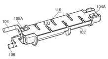
도 2는 일부 실시예들에 따른 도 1의 에어로졸 제공 시스템(10)의 카트리지 어셈블리(30)에 사용하기 위한 가열 엘리먼트 캐리어 모듈(160)의 컴포넌트들을 개략적으로 표현한다. 도 3 내지 6은 가열 엘리먼트 캐리어 모듈(160)의 상이한 어셈블리 스테이지들에서 도 2에 표현된 컴포넌트들을 개략적으로 표현한다.FIG. 2 schematically represents components of a heating
캐리어 모듈(160)은 제 1 캐리어 컴포넌트(제 1 부분)(101) 및 제 2 캐리어 컴포넌트(제 2 부분)(102)를 포함한다. 아래에 추가로 설명되는 바와 같이, 이들 2개의 컴포넌트들(101, 102)은 가열 엘리먼트(103)를 지지하는 역할을 하고, 그리고 이에 관하여 때때로 가열 엘리먼트 크래들(cradle)을 제공하는 것으로 언급될 수 있다. 따라서, 도 2에 표현된 제 1 및 제 2 컴포넌트들(101, 102)은 편의상, 그리고 도면들에 표현된 배향에 관하여 또한 상부 크래들(101) 및 하부 크래들(102)로서 지칭될 수 있다. 그러나, 용어들 "상부" 및 "하부", 및 유사한 배향-관련 용어들이 본원에서 순수하게 편의상 첨부 도면들에 표현된 엘리먼트들을 지칭하는데 사용되고 그리고 이들 컴포넌트들에 대한 임의의 특정 배향이 본원에 설명되는 다양한 실시예들을 구현하기 위하여 요구되는 것을 표시하도록 의도되지 않는 것이 인지될 것이다. 캐리어 모듈(160)은 추가로 가열 엘리먼트(103) 및 가열 엘리먼트(103)의 제 1 단부에 연결하기 위한 제 1 전기 접촉 엘리먼트(104) 및 가열 엘리먼트(103)의 제 2 단부에 연결하기 위한 제 2 전기 접촉 엘리먼트(105)를 포함한다.The
이 예에서 상부 및 하부 크래들 컴포넌트들(101, 102)은 고온들, 예컨대 약 섭씨 230 도의 온도들에 대한 개선된 강성 및 저항을 제공하기 위하여 높은 유리 섬유 함량(예컨대 50%)을 가지는 플라스틱 재료로 몰딩된다. 개별 상부 및 하부 크래들 컴포넌트들은 대체로 일반적으로 반원 단면을 갖는 것으로 말해진다(비록 아래에서 추가로 논의되는 바와 같이 자신의 길이들을 따라 사이즈 및 모양에 변동들을 가지더라도). 각각의 크래들 컴포넌트에는 그렇지 않으면 자신의 가장 편편한 면들일 것인 자신의 길이를 따라 연장되는 리세스(120)(도 2에서 하부 크래들 컴포넌트(102)에 대해서만 보여짐)가 제공되어, 2개의 크래들 컴포넌트들이 아래에서 추가로 논의되는 바와 같이 가열 엘리먼트(103)를 샌드위치하기 위하여 합쳐질 때 2개의 크래들 컴포넌트들은 튜브의 내부 아래로 이어지고 그리고 가열 엘리먼트(103)가 배치되는 공기흐름 경로(개별 리세스들(120)에 의해 정의됨)를 가지는 일반적으로 튜브 구성을 가지는 크래들을 형성한다.The upper and
제 1 및 제 2 전기 접촉 엘리먼트들(104, 105)은 종래의 제조 기법들에 따라 장치의 다른 엘리먼트들의 모양 및 구성에 관련하여 예컨대 적합한 모양으로 형성되는 구리 스트립들을 포함하는 시트 금속 재료로 형성될 수 있다. 다른 경우들에서, 제 1 및 제 2 전기 접촉 엘리먼트들(104, 105)은 종래의 유연한 와이어링(wiring)을 포함할 수 있다. 일부 예들에서, 제 1 및/또는 제 2 전기 접촉 엘리먼트들에는 도금, 예컨대 금 도금이 제공되어, 더 낮은 접촉 저항을 돕고 및/또는 임의의 부식 위험을 감소시킬 수 있다.The first and second
가열 엘리먼트(103)는 소결된 금속 섬유 재료로 형성되고 그리고 일반적으로 시트 형태이다. 그러나, 다른 다공성 전도 재료들이 똑같이 사용될 수 있다는 것이 인지될 것이다. 이런 특정 예에서, 가열 엘리먼트(103)는 개별 전기 접촉 엘리먼트들(104, 105)에 연결하기 위한 각각의 단부 전기 접촉 연장부들(103B)과 함께 메인 부분(103A)을 포함한다. 이 예에서 전기 접촉 연장부들(103B) 간의 가열 엘리먼트의 전체 저항은 약 1 오움이다. 그러나, 예컨대 이용가능한 배터리 전압 및 가열 엘리먼트의 원하는 온도/전력 손실 특성들에 관련하여 다른 저항들이 선택될 수 있다는 것이 인지될 것이다. 이에 관하여, 관련 특성들은 관심 있는 소스 액체에 대한 에어로졸 생성의 설정된 원리들에 따른 장치에 대해 원하는 에어로졸 생성 특징들에 따라 선택될 수 있다. 가열 엘리먼트의 메인 부분(103A)은 일반적으로 약 20 mm의 길이(즉, 전기 접촉 연장부들(103B) 간에 이어지는 방향으로) 및 약 8 mm의 폭을 가지는 직사각형이다. 이 예에서 가열 엘리먼트(103)를 포함하는 시트의 두께는 약 0.15 mm이다. 도 2에서 보여질 수 있는 바와 같이, 가열 엘리먼트(103)의 일반적으로-직사각형 메인 부분(103A)은 더 긴 측들의 각각으로부터 안쪽으로 연장되는 슬롯들을 가진다. 슬롯들은 약 4.8 mm만큼 안쪽으로 연장되고 약 0.6 mm의 폭을 가진다. 안쪽으로 연장되는 슬롯들은 가열 엘리먼트의 각각의 측 상에서 약 5.4 mm 만큼 서로 분리되고 이때 대향 측들로부터 안쪽으로 연장되는 슬롯들은 이런 간격의 약 절반만큼 서로 오프셋된다. 가열 엘리먼트에서 슬롯들의 이런 어레인지먼트(arrangement)의 결과는, 가열 엘리먼트를 따른 전류 흐름이 사실상 구불구불한 경로를 따르게 강제되어 슬롯들의 단부들 주위에서 전류, 및 따라서 전기 전력의 집중을 유발하는 것이다. 가열 엘리먼트의 상이한 위치들에서 상이한 전류/전력 밀도들은, 비교적 낮은 전류 밀도의 영역들보다 더 뜨거워지는 비교적 높은 전류 밀도의 영역들이 있다는 것을 의미한다. 이것은 실제로 가열 엘리먼트에 다양한 상이한 온도들을 제공하고 그리고 온도 기울기들을 증가시키고, 이는 에어로졸 제공 시스템들의 맥락에서 바람직할 수 있다. 이것은, 소스 액체의 상이한 컴포넌트들이 상이한 온도들에서 에어로졸화/증기화할 수 있기 때문이고 따라서 가열 엘리먼트에 다양한 온도들을 제공하는 것은 소스 액체의 다양한 상이한 컴포넌트들을 동시에 에어로졸화하는 것을 도울 수 있다.The
특정 실시예들에 따라 전자 담배(10)의 카트리지 어셈블리(30)에 사용하기 위한 가열 엘리먼트 캐리어 모듈(160)을 제공하기 위하여 도 2에 표현된 컴포넌트들을 어셈블링하는 프로세스는 이제 도 3 내지 6을 참조하여 설명된다.The process of assembling the components represented in FIG. 2 to provide a heating
도 3에서 보여질 수 있는 바와 같이, 제 1 및 제 2 전기 접촉 엘리먼트들(104, 105)은 하부 크래들 컴포넌트(102)에 장착되었고 그리고 가열 엘리먼트(103)는 적소에 넣어지도록 준비된 하부 크래들 컴포넌트(102) 위에 표현된다. 제 2 전기 접촉 엘리먼트(105)는 하부 크래들 컴포넌트(102)의 제 2 단부(도 3의 배향에 대해 최좌측 단부)에 장착된다. 하부 크래들 컴포넌트(102)는 플라스틱 바디 부분들에 전기 전도체들을 장착하기 위한 종래의 제조 기법들에 따라 제 2 전기 접촉 엘리먼트(105)의 제 1 부분의 모양을 수용 및 매치하도록 프로파일링(profile)된다. 도면에 개략적으로 표현된 바와 같이, 제 2 전기 접촉 엘리먼트(105)의 하나의 단부는 가열 엘리먼트(103)의 전기 접촉 연장부들(103B) 중 하나를 수용하기 위한 제 2 전기 접촉 엘리먼트 클램프(clamp) 부분(105A)을 제공하는 반면 제 2 전기 접촉 엘리먼트(105)의 다른 단부는 하부 크래들 컴포넌트(102)로부터 멀어지게 연장된다. 제 1 전기 접촉 엘리먼트(104)는 리세스(120)의 벽에 인접한 하부 크래들 컴포넌트(102)의 길이를 따라 연장하도록 장착된다. 제 2 전기 접촉 엘리먼트(105)에 대해, 제 1 전기 접촉 엘리먼트(104)의 하나의 단부는 도면에 개략적으로 표현된 바와 같이 하부 크래들 컴포넌트(102)의 제 2 단부로부터 멀어지게 연장된다. 제 1 전기 접촉 엘리먼트(104)의 다른 단부는 가열 엘리먼트(103)의 전기 접촉 연장부들(103B) 중 다른 연장부를 수용하기 위하여 하부 크래들 컴포넌트(102)의 제 1 단부(도 3에서 최우측 단부)에 배열된 제 1 전기 접촉 엘리먼트 클램프 부분(105A)을 제공한다.As can be seen in FIG. 3 , the first and second
도 3에 보여질 수 있는 바와 같이, 하부 크래들 컴포넌트(102)의 상부 표면은 위에서 논의된 가열 엘리먼트의 슬롯들과 정렬하는 복수의 위치결정 페그(peg)들(110) 및 상부 크래들(101)의 대응하는 위치결정 홀들(도면들에서 도시되지 않음)을 포함한다. 이들 위치결정 페그들은 상부 크래들(101)을 하부 크래들(102)과 정렬시키는 것을 돕고, 그리고 어셈블리될 때 상부 및 하부 크래들(102)에 관련하여 가열 엘리먼트(103)를 정렬시키는 것을 돕는다.As can be seen in FIG. 3 , the upper surface of the
도 4는 제 1 및 제 2 전기 접촉 엘리먼트들(104, 105)을 포함하는 하부 크래들(102)에 장착된 가열 엘리먼트(103)를 개략적으로 도시한다. 가열 엘리먼트(103)는 가열 엘리먼트(103)의 슬롯들과 정렬되는 위치결정 페그들(110)에 의해 하부 크래들의 상부 표면상에 위치됨으로써 간단히 하부 크래들에 장착된다. 하부 크래들 엘리먼트(102)의 상부 표면의 약간 융기된 부분들은 가열 엘리먼트를 추가로 정렬시키는 것을 돕기 위하여 가열 엘리먼트(103)의 각각의 단부에 있는 전기 접촉 연장부들(103B) 부근에 위치결정 벽들(111)을 제공한다. 이 예에서, 위치결정 벽들은 가열 엘리먼트의 사이즈보다 약간 더 크게 분리되고 위치결정 페그들은 슬롯들의 사이즈보다 약간 더 작아서, 가열 엘리먼트는 예컨대 약 0.1 mm 만큼 수평 평면에서 대체로 약간 자유롭게 이동한다. 이것은 가열 엘리먼트가 휘어지는 것을 회피하는 것을 돕기 위하여 사용될 때 열적 팽창 및 수축을 허용하는 것이다. 제 1 및 제 2 전기 접촉 엘리먼트 클램핑 부분들(104A, 105A)은 가열 엘리먼트(103)의 각각의 단부에서 전기 접촉 연장부들(103B) 중 개별 연장부들 주위에서 클램핑하도록 아래로 구부러지고, 따라서 하부 크래들 컴포넌트(102)로부터 멀어지게 연장되는 전기 접촉 엘리먼트들(104, 105)의 부분들과 가열 엘리먼트(103)의 단부들 간에 전기 접속을 제공한다. 이 예에서, 전기 접촉 엘리먼트들(104, 105)과 가열 엘리먼트(103) 간의 전기 접속들은 유일하게 물리적 접촉에 의존하지만, 다른 구현들에서 다른 기법들, 예컨대 용접 또는 납땜은 사용될 수 있다.4 schematically shows a
도 5는 도 4에 표현된 바와 같이 결합된 하부 크래들 컴포넌트(102), 제 1 및 제 2 전기 접촉 엘리먼트들(104, 105) 및 가열 엘리먼트(103)를 개략적으로 도시하지만, 다른 크래들 컴포넌트(101)가 하부 크래들 컴포넌트에 장착될 준비가 된 것으로 도시된다.FIG. 5 schematically shows the
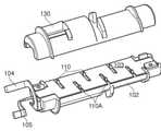
도 6은 어셈블리된 캐리어 모듈(160)을 제공하기 위하여 하부 크래들 컴포넌트(102)(및 도 4에 표현된 다른 엘리먼트들)에 장착된 상부 크래들 컴포넌트(101)를 개략적으로 도시한다. 상부 크래들 컴포넌트(101)는 상부 크래들 컴포넌트(101)의 대응하는 위치결정 홀들(도시되지 않음)과 정렬된 하부 크래들 컴포넌트의 위치결정 페그들(110)과 함께 상부 크래들 컴포넌트(101)와 하부 크래들 컴포넌트(102)를 간단히 배치함으로써 하부 크래들 컴포넌트(102)에 장착된다. 도 4 및 5에서 보여질 수 있는 바와 같이, 위치결정 페그들(110)에는 각각 어깨부(110A)가 제공된다. 어깨부들(110A)은 하부 크래들 컴포넌트(102)의 상부 표면을 초과하는 약 0.18 mm의 높이를 가지며(즉, 가열 엘리먼트의 두께보다 0.03 밀리미터 더 큼), 그리고 이것은 또한 위치결정 벽들(111)의 높이에 매치한다. 어깨부들(110A)은 가열 엘리먼트의 슬롯들 내에 속하도록 사이즈가 정해지고 배열된다. 그러나, 상부 크래들의 대응하는 위치결정 홀들은 이들 어깨부들이 아닌 위치결정 페그들만을 수용하도록 사이즈가 정해진다. 따라서, 상부 크래들 컴포넌트(101)가 하부 크래들 컴포넌트(102)에 장착될 때, 이들은 어깨부들(110A)과 위치결정 벽들(111)의 높이에 대응하는 갭만큼 분리된다. 상부 크래들 컴포넌트와 하부 크래들 컴포넌트 간의 이런 갭이 0.18 mm이고, 그리고 가열 엘리먼트가 0.15 mm의 두께를 가지기 때문에, 가열 엘리먼트는 적소에 고정되게 클램핑되기 보다, 상부 크래들 컴포넌트와 하부 크래들 컴포넌트 간에 느슨하게 샌드위치된다. 위에서 주목되는 바와 같이, 가열 엘리먼트의 이런 느슨한 장착은 사용 동안 가열 엘리먼트의 열적 팽창 및 수축을 허용할 것이다.6 schematically shows an
따라서, 어셈블리된 캐리어 모듈(160)은 일반적으로 캐리어 모듈을 통한 공기흐름 경로를 제공하는 상부 및 하부 캐리어 컴포넌트들의 개별 리세스들(120)에 의해 정의되는 중앙 통로를 가진 관 모양이다. 이 예에서, 상부 및 하부 캐리어 컴포넌트들에 의해 정의되는 공기흐름 경로는 약 4 mm의 폭 및 약 2.2 mm의 높이를 가지는 일반적으로 직사각형 단면을 가지며 그리고 가열 엘리먼트(103)는 공기흐름 경로의 중간 정도의 평면에 배치된다. 캐리어 모듈(160)은 약 2.5 cm의 전체 길이 및 폭이 약 1 cm인 직경을 가진다. 캐리어 모듈의 외부 표면(제 1 및 제 2 크래들 컴포넌트들의 개별 외부 표면들에 의해 제공됨)은 다양한 표면 프로파일 피처들을 포함한다. 가장 특히, 캐리어 모듈은 캐리어 모듈(160)의 다른 단부쪽에 배열된 제 2 부분(108)(도 6의 최좌측)의 단면적보다 작은 단면적을 가지는 캐리어 모듈(160)의 한쪽 단부쪽에 배열된 제 1 부분(107)(도 6의 최우측)을 포함한다. 캐리어 모듈(160)의 제 1 및 제 2 부분들(107, 108)은 가열 엘리먼트(103)의 평면에서(즉, 상부 및 하부 크래들 컴포넌트들 간의 인터페이스에서) 대략 동일한 폭을 가지지만, 가열 엘리먼트(103)의 평면에 수직 방향으로 상이한 두께를 가진다. 따라서, 더 큰 제 2 부분(108)은 일반적으로 원형 단면을 가지는 반면, 더 작은 제 1 부분(101)은 일반적으로 가늘고 긴 단면(아래에서 추가로 논의되는 도 11 참조)을 가진다. 따라서, 캐리어 모듈의 길이를 따라 대략 중간에서 캐리어 모듈 단면적의 계단적 변화가 존재한다. 캐리어 모듈의 외부 표면은 다수의 돌출부들(140), 캐리어 모듈의 더 큰 제 2 부분(108)의 리세스에 의해 정의되는 챔버(130), 및 챔버(130)로부터, 캐리어 모듈의 더 큰 제 2 부분(108)이 캐리어 모듈(160)의 더 작은 제 1 부분(107)과 만나는 장소로 연장되는 캐리어 모듈의 더 큰 제 2 부분(108)의 외부 표면상의 편평한 지역(131)을 더 포함한다. 비록 도 6에서 자명하지 않지만, 상부 크래들 컴포넌트는 또한 캐리어 모듈의 내부를 통해 이어지는 흐름 경로(120)와 챔버(130) 간을 연결하는 통로를 포함한다. 이들 피처들은 이들의 제조 동안 개별 크래들 컴포넌트들로 몰딩될 수 있고 그리고 이들 다양한 엘리먼트들의 개별 기능들은 아래에서 추가로 논의된다.Accordingly, the assembled
도 7은 특정 실시예들에 따른 도 6의 캐리어 모듈(160)을 포함하는 카트리지 어셈블리(30)의 일부 추가 컴포넌트들을 개략적으로 표현한다. 더 구체적으로, 도 7은 제 1 밀봉 엘리먼트(밀봉 링)(171), 지지 튜브(172) 형태의 제 2 밀봉 엘리먼트, 및 카트리지 어셈블리에 대한 외부 하우징(180)을 도시한다. 이들 컴포넌트들은 플라스틱 재료, 예컨대 폴리프로필렌으로 몰딩될 수 있다.7 schematically represents some additional components of the
도 8은, 어떻게 제 1 및 제 2 밀봉 엘리먼트들(171, 172)이 캐리어 모듈(160)에 장착되는지를 개략적으로 표현한다.FIG. 8 schematically represents how the first and
제 1 밀봉 엘리먼트(171)는 캐리어 모듈의 제 2 단부(도 8의 최좌측)를 수용하기 위한 리세스를 포함한다. 제 1 밀봉 엘리먼트의 리세스는 도 6에 도시된 최좌측 돌출부(140)의 좌측 및 이 돌출부에 대해 위에 있는 캐리어 모듈(160)의 부분을 수용하도록 사이즈가 정해진다. 제 1 밀봉 엘리먼트(171)는 마찰 및/또는 스냅 피팅(snap fitting)에 의해 캐리어 모듈(160)에 고정될 수 있다. 제 1 밀봉 링(171)은 개구들을 더 포함하고, 상기 개구들을 통해 캐리어 모듈(160)로부터 멀어지게 연장되는 제 1 및 제 2 전기 접촉 엘리먼트들(104, 105)의 개별 부분들이 지나가고, 이에 의해 개별 전기 접촉 엘리먼트들(104, 105)에 의해 제 1 밀봉 링(171)을 통해 가열기와의 전기적 접촉이 설정되게 된다. 제 1 밀봉 엘리먼트는 추가로 캐리어 모듈을 통한 공기흐름 경로와 정렬하는 중앙 개구를 포함한다. 이런 중앙 개구에는 공기가 가열 엘리먼트(103)의 어느 한 측으로 캐리어 모듈 내로 끌어당겨지게 지향시키는 것을 돕도록 배열된 공기흐름 편향기 엘리먼트가 제공될 수 있다.The
제 2 밀봉 엘리먼트(지지 튜브)(172)는 캐리어 모듈(160)의 제 1 단부(도 8의 최우측)를 수용하기 위한 리세스를 포함한다. 제 2 밀봉 엘리먼트의 리세스는 도 6에 도시된 최우측 돌출부(140)의 우측 및 이 돌출부에 인접하여 있는 캐리어 모듈(160)의 부분을 수용하도록 사이즈가 정해진다. 제 2 밀봉 엘리먼트(172)는 또한 마찰 및/또는 스냅 피팅에 의해 캐리어 모듈(160)에 고정될 수 있다. 제 2 밀봉 엘리먼트(172)는 캐리어 모듈(160)을 통한 공기흐름 경로에 연장부를 제공하는 중앙 개구를 가진 중공이다.The second sealing element (support tube) 172 includes a recess for receiving the first end (rightmost in FIG. 8 ) of the
도 9는 외부 하우징(180)에 삽입을 위한 준비가 된 결합된 밀봉 링(171), 캐리어 모듈(160) 및 지지 튜브(172)를 개략적으로 도시한다. 따라서, 결합된 캐리어 모듈 및 밀봉 엘리먼트들은 도 10에 개략적으로 표현된 카트리지 어셈블리(30)를 제공하도록 외부 하우징(180)에 간단히 삽입될 수 있다. 또한 도 10에는 외부 하우징(180)의 일부 위에 배치될 수 있는 마우스피스 커버(190)가 도시된다. 외부 하우징은 외부 하우징(180) 상에 마우스피스 커버를 위치시키는 것을 돕기 위하여 외부 하우징 상에 마우스피스 커버를 위치결정하기 위한 스냅 피팅 맞물림을 제공하도록 마우스피스 커버(190)의 대응하게 사이즈가 정해진 개구(191)에 매치하는 융기된 부분(182)을 가진다. 마우스피스 커버는 심미적 및/또는 위생 이유들 때문에 제공될 수 있고, 그리고 사용자들이 맨(bare) 플라스틱보다 더 좋은 느낌인 것을 감지할 수 있는 것을 제공하기 위하여, 표면 질감, 예컨대 고무가 입혀진 질감이 추가로 제공될 수 있다. 융기된 부분(182)은 외부 하우징의 내부가 보여지게, 예컨대 카트리지 어셈블리(30)에 대한 충진 레벨을 알 수 있게 하도록 투명할 수 있다.9 schematically shows the combined
지지 튜브(172)의 최우측 단부는 외부 하우징(180)의 최우측 단부에 있는 대응하게 사이즈가 정해진 리세스에 수용된다. 밀봉 링(171)은 외부 하우징(180)의 최좌측 단부에 수용된다. 밀봉 링(171) 둘레의 순응하는 밀봉부는 외부 하우징(180)의 내부 표면과 밀봉을 형성한다. 결합된 밀봉 엘리먼트들 및 캐리어 모듈은 스냅 및/또는 마찰 피팅에 의해 외부 하우징(180)에 피팅될 수 있다. 예컨대, 이 예에서 밀봉 링(171)에는 스냅 피팅을 제공하기 위하여 외부 하우징(180)의 내부 벽 내의 개구에 수용되는 돌출부(220)가 제공된다. 일 실시예에서, 상기 외부 하우징 내의 정의된 포지션에서 상기 캐리어 모듈을 지지하도록 배열되는 하나 또는 그 초과의 스페이서(spacer) 엘리먼트들을 더 포함하고, 상기 하나 또는 그 초과의 스페이서 엘리먼트들은 상기 외부 하우징의 내부 표면상에 형성되는 하나 또는 그 초과의 돌출부들(140)을 포함한다. 위에서 언급된 캐리어 모듈(160) 상의 돌출부들(140)은, 캐리어 모듈이 외부 하우징(180)에 관련하여 적소에 캐리어 모듈을 홀딩하도록 외부 하우징(180)으로 삽입될 때, 외부 하우징(180)의 내부 벽에 접하도록 사이즈가 정해진다. 외부 하우징(180)은 캐리어 모듈(160)을 둘러싸는 일반적으로 원통형 부분 및 지지 튜브(172)를 둘러싸는 일반적으로 테이퍼링(tapering) 부분을 가진다. 외부 하우징(180)은, 캐리어 모듈(160)의 더 큰 제 2 부분(108)과 외부 하우징(180)의 내부 벽 간에 예컨대 약 0.5 mm 또는 그 미만인 비교적 작은 갭, 및 캐리어 모듈의 더 작은 제 1 부분(107)과 외부 하우징(180)의 내부 벽 간에 비교적 큰 갭이 있도록, 일반적으로 균일한 벽 두께를 가진다. 테이퍼링 갭은 지지 튜브(172)와 외부 하우징(180)의 테이퍼링 부분의 내부 벽 간에 제공되고, 테이퍼링 갭은 지지 튜브(172)의 단부가 외부 하우징(180)의 단부에 수용되는 장소쪽으로 감소한다.The rightmost end of the
캐리어 모듈(160)의 외부 벽과 외부 하우징(180)의 내부 벽 간의 공간은 카트리지 어셈블리(30)에 대한 소스 액체 저장소(38)의 적어도 일부를 정의한다. 이 예에서, 소스 액체에 대한 저장소(38)는 지지 튜브(172)와 외부 하우징(180)의 테이퍼링 부분의 내부 벽 간에 갭을 더 포함한다. 이 저장소는 충진 후, 예컨대 플러깅에 의해 밀봉되는 외부 하우징(도시되지 않음)의 개구를 통해 소스 액체가 충진될 수 있다.The space between the outer wall of the
정상 사용 동안 카트리지 어셈블리(30)의 최좌측 단부는 카트리지 어셈블리가 연결되는 전자 에어로졸 제공 시스템의 바디 부분에 카트리지를 제거가능하게 맞물림하기 위한 맞물림 메커니즘을 포함한다. 이 예에서, 맞물림 메커니즘은 카트리지 어셈블리가 사용되도록 의도되는 전자 에어로졸 제공 시스템의 바디 부분 상의 대응하는 메일(male) 나사 스레드(thread)와 협력하기 위한 부분적(예컨대, 1 회전 미만) 피메일(female) 나사 스레드를 포함한다. 예컨대 대략 바요넷, 마찰 또는 스냅 피팅에 기반하는 다른 맞물림 메커니즘들은 다른 구현들에 사용될 수 있다. 카트리지 어셈블리(30)가 사용되도록 의도되는 전자 에어로졸 제공 시스템의 바디 부분(20)에는 가열기(103)와 바디 부분(20) 간의 전기적 연결을 설정하기 위하여 밀봉 엘리먼트(171)를 통하여 연장되는 제 1 및 제 2 전기적 접촉 엘리먼트들(104, 105)의 부분들과 협력하기 위한 전기적 연결기들이 제공된다. 이것은 제거가능 엘리먼트들 간의 표준 전기적 연결들을 위한 종래의 기법들을 따라, 예컨대 스프링-로딩된 컬렉터 핀들을 사용하여 달성될 수 있다.The leftmost end of the
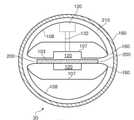
도 11은 도 10에 표현된 카트리지 어셈블리(30)의 일부 양상들을 개략 단면도로 개략적으로 표현한다. 단면은 공기흐름 경로(120)에 수직(즉, 장치가 정상 사용 중일 때 공기흐름 경로에서 공기가 흐르는 방향에 수직)인 평면에서 캐리어 모듈(160)의 제 1 부분(107)(즉, 더 작고/더 얇은 부분)의 단면을 통해 취해진다. 도 11에 표현된 단면은, 도면이 또한 단면의 평면에 있지 않은 카트리지 어셈블리의 추가 양상들을 개략적으로 표현한다는 점에서 엄격한 단면이 아니다. 특히, 도면은 또한 캐리어 모듈(160)의 제 2(더 크고/더 두툼한) 부분의 외부 주변부뿐 아니라 캐리어 모듈의 이 부분에서의 챔버(130) 및 이 챔버와 공기흐름 경로(120) 간을 연결하는 통로(132)(챔버(130)와 통로(132)는 점선들에 의해 표현됨)를 표현한다. 위에서 설명된 바와 같이, 상부 및 하부 크래들 컴포넌트는, 가열기(103)가 배열되는 갭(갭은 바람직하게 가열기(103)의 두께보다 약간 더 큼)을 정의하는 방식으로 맞물리도록 구성된다. 이 갭은 소스 액체에 대한 저장소(이의 일부)를 함께 정의하는 캐리어 모듈(160)의 외부 벽과 외부 하우징(180)의 내부 벽 간의 공간과 유체 연통한다.11 schematically represents, in schematic cross-sectional view, some aspects of the
따라서, 상부 및 하부 크래들 컴포넌트들 간의 갭은 가열 엘리먼트(103)의 양 측들을 따라 연장되는 모세관 채널들(200)을 제공하고 모세관 채널들(200)을 통해 소스 액체는 사용 동안 공기흐름 경로(120)에서 에어로졸을 생성하기 위한 증기화를 위해 저장소로부터 가열 엘리먼트로 끌어당겨질 수 있다. 그 다음으로, 가열기에서 생성된 에어로졸은 사용자가 카트리지 어셈블리(30)를 포함하는 전자 담배(10)를 흡입할 때, 공기흐름 경로(120)를 따라 그리고 지지 튜브(172)를 통해 끌어당겨져서, 외부 하우징(180)의 마우스피스 단부(즉, 마우스피스 커버(190)에 의해 커버되는 부분)를 통하여 카트리지 어셈블리(30)를 떠나갈 수 있다.Thus, the gap between the upper and lower cradle components provides
캐리어 모듈과 외부 하우징 간의 공간에 의해 정의되는 저장소와 공기흐름 경로(120) 간에 유체 연통을 제공하는 통로(132)는 모세관 갭(200)을 통하여 끌어당겨지고 증기화되는 소스 액체를 대체하기 위하여 공기가 공기흐름 경로(120)로부터 저장소에 진입하게 한다(즉, 통로(132)는 공기흐름 경로(120)와 소스 액체의 저장소 간의 압력 밸런싱(balancing)/공기 통풍을 허용함). 챔버(130)는 저장소의 퍼프(puff) 동안 소스 액체가 이 지역에 일시적으로 축적되게 하도록 제공된다. 본 발명자들은, 이 구성이 통로(132)를 통하여 공기흐름 경로(120)로 소스 액체가 누설되는 기회를 감소시키는 것을 발견하였다. 챔버(130)와 캐리어 모듈의 더 얇은 부분(107)에 인접한 저장소 부분 간을 연결하는 편평한 지역(131)(도 6 참조)이, 공기가 캐리어 모듈(160)의 더 큰 부분(108)과 외부 하우징(180) 간의 저장소의 더 얇은 부분에 갇히기보다 챔버(130)로부터 캐리어 모듈(160)의 제 1 부분(107)에 인접한 저장소의 메인 바디로 통과하는 것을 보장하는 것을 돕는 것이 발견되었다.A
따라서, 특정 실시예들은 전자 에어로졸 제공 시스템(예컨대, 전자 담배)에 대한 장치(예컨대, 카트리지 어셈블리)를 제공한다. 카트리지 어셈블리는 소스 액체에 대한 저장소 및 저장소 내에 공기흐름 경로(120)를 정의하고 공기흐름 경로에 지지되는 가열 엘리먼트(103)를 포함하는 캐리어 모듈을 포함한다. 캐리어 모듈은 가열 엘리먼트를 지지하도록 협력하여 맞물리는 제 1 부분(상부 크래들 컴포넌트) 및 제 2 부분(하부 크래들 컴포넌트)을 포함하고, 제 1 부분과 제 2 부분들 간의 갭은 저장소로부터 가열 엘리먼트로 소스 액체를 끌어당기도록 배열된 모세관 채널들(200)을 제공한다.Accordingly, certain embodiments provide a device (eg, a cartridge assembly) for an electronic aerosol delivery system (eg, an electronic cigarette). The cartridge assembly includes a carrier module including a reservoir for a source liquid and a
본 발명자들은 이것이 누설을 갖는 문제들이 생기지 않고 가열 엘리먼트에 소스 액체의 효과적인 공급을 제공하는 구성인 것을 발견하였다.The inventors have found that this is a configuration that provides an effective supply of the source liquid to the heating element without causing problems with leakage.
위에서 설명된 바와 같이, 상부 및 하부 크래들 컴포넌트들은, 장치가 정상 사용 중일 때 공기가 공기흐름 경로로 흐르는 방향에 실질적으로 평행한 방향으로 연장되는 인터페이스에서 협력하여 맞물린다. 홀더(크래들)를 사실상 분리하고 홀더의 2개의 부분들 간의 인터페이스 평면에 가열 엘리먼트를 배열함으로써, 가열 엘리먼트는 자신의 주변부의 비교적 큰 부분 둘레에 지지될 수 있고, 그리고 이것은 가열 엘리먼트들의 비교적 부서지기 쉬운 성질로 인해 도움이 될 수 있다. 게다가, 2-부분 구성은, 소스 액체를 인근 저장소로부터 가열 엘리먼트로 끌어당기기 위한 적합하게 사이즈가 정해진 모세관 갭들을 정의하기 위한 준비된 메커니즘을 제공하면서, 제조 및 어셈블리를 돕는 것으로 발견되었다.As described above, the upper and lower cradle components cooperatively engage at an interface extending in a direction substantially parallel to the direction in which air flows into the airflow path when the device is in normal use. By substantially separating the holder (cradle) and arranging the heating element in the plane of the interface between the two parts of the holder, the heating element can be supported around a relatively large portion of its periphery, which makes the heating elements relatively brittle. It can be helpful because of its nature. Furthermore, a two-part configuration has been found to aid in manufacturing and assembly, providing a ready mechanism for defining suitably sized capillary gaps for drawing source liquid from a nearby reservoir to the heating element.
도 11에서 보여질 수 있는 바와 같이, 상부 및 하부 크래들 부분들에는 둥근 모서리들이 제공되어, 모세관 갭을 정의하는 상기 크래들 부분들 사이의 갭은 공기흐름 경로(120)로부터 거리가 증가함에 따라 증가한다. 본 발명자들은 이것이 사용 동안 가열기(103)에 소스 액체의 적합한 공급을 유지하는 것을 추가로 돕는 것을 발견하였다. 그러나, 다른 예시적 실시예들에서, 모세관 갭은 폭이 증가하지 않을 수 있고 상부 및 하부 크래들 부분들의 에지들까지 동일한 폭을 유지할 수 있다.As can be seen in FIG. 11 , the upper and lower cradle portions are provided with rounded corners such that the gap between the cradle portions defining a capillary gap increases with increasing distance from the
위에서 주목되는 바와 같이, 캐리어 모듈의 제 1(더 얇은) 부분(107)을 따라 캐리어 모듈과 외부 하우징 간의 공간은 캐리어 모듈의 제 2(더 두툼한) 부분을 따라 캐리어 모듈과 외부 하우징 간의 공간보다 더 크다. 이런 접근법은 여전히 합리적인 저장소 수용량을 허용하면서, 카트리지 어셈블리(30)의 상이한 배향들에 대해 가열 엘리먼트에 소스 액체의 적합한 공급을 유지하는 것을 돕는 것으로 발견되었다. 이것은, 캐리어 모듈의 제 1 부분을 따라 캐리어 모듈과 외부 하우징 간의 공간이 합리적인 수용량을 제공하도록 공기흐름 경로 주위에 있는 소스 액체의 대부분을 저장하기 위한 저장소의 메인 바디를 정의하기 때문이다. 그러나, 캐리어 모듈의 제 2(더 두툼한) 부분을 따라 캐리어 모듈과 외부 하우징 간의 공간은 캐리어 모듈의 제 2 부분을 따라 캐리어 모듈 둘레로 연장되는 환형 모세관 공간(210)을 정의하도록 사이즈가 정해진다. 이런 환형 모세관 공간(210)은 실제로 카트리지 어셈블리(30)의 배향에 상관없이 가열 엘리먼트로 끌어당겨지게 소스 액체를 저장할 수 있다.As noted above, the space between the carrier module and the outer housing along the first (thinner)
다른 실시예들에 따라 채택될 수 있는 위에서 설명된 구성들에 대한 다양한 수정들이 존재하는 것이 인지될 것이다.It will be appreciated that there are various modifications to the configurations described above that may be employed in accordance with other embodiments.
예컨대, 위의 구현에서 갭이 가열 엘리먼트(103)의 양측들 상에 제공되는 반면, 일부 구성들에서 가열 엘리먼트의 일 측이 차단될 수 있어서, 단지 하나의 모세관 채널만이 가열 엘리먼트에 소스 액체를 공급하도록 제공된다.For example, while in the above implementation a gap is provided on both sides of the
게다가, 도 11에 표현되는 예시적인 구현에서 가열 엘리먼트(103)가 모세관 갭(200) 내에 포함되는 반면, 일부 다른 예시적인 구현들에서, 가열 엘리먼트(103)는 모세관 갭(200)을 넘어 저장소로 연장될 수 있다.Moreover, while in the exemplary implementation represented in FIG. 11 the
게다가, 위에서 설명된 예시적인 구현들에서, 캐리어 모듈(140)에는 외부 하우징(180) 내에 캐리어 모듈을 위치시키는 것을 돕기 위한 돌출부들(140)이 제공된 반면, 다른 구현들에서 외부 하우징의 내부 벽에 대신, 또는 부가하여 이런 목적을 위한 돌출부들이 제공될 수 있다.Moreover, in the example implementations described above, the
일부 구현들에서, 챔버(130)는 제공되지 않을 수 있고, 따라서 도 11에 도시된 공기 통로(132)는 실제로, 통로(132)가 제공되는 크래들 컴포넌트(즉, 도 11에 표현된 예에서 상부 크래들 컴포넌트)의 외부 표면으로 연장될 것이다.In some implementations, the
게다가, 위에서-설명된 예들에서 편평한 지역(131)이 챔버(130)로부터 제 1 부분(107)에 인접한 저장소의 메인 바디로 직접 직선으로 연장되는 반면, 다른 구현에서 편평한 지역(131)은 대신 챔버(130)(또는 챔버가 없는 경우에는 통로(132)의 단부)로부터 저장소의 메인 바디로 비직선 경로를 따를 수 있다. 이것은 편평한 지역의 전체 길이를 증가시키기 위해서일 수 있고, 이에 의해 유체 흐름에 대한 그의 효과적인 저항이 증가된다. 또 다른 예들에서, 편평한 지역(131)은 크래들 컴포넌트의 외부 표면에 형성된 그루브에 의해 대체될 수 있고, 그리고 이것은 직선일 수 있거나 자신의 흐름 저항을 증가시키기 위하여 구불구불한 경로를 따를 수 있다.Moreover, while in the above-described examples the
또 다른 예시적인 구현들에서, 통로(132)가 없을 수 있다(그리고 챔버(130)가 없고; 그리고 그루브 또는 편평한 지역(131)이 없음). 대신, 공기흐름 경로(120)와 저장소(38) 간의 압력 밸런싱은 (갭이 가열 엘리먼트의 두께보다 더 넓을 수 있기 때문에) 가열 엘리먼트(103)에 의해 점유되지 않은 그 갭들의 부분들에서의 공기 흐름에 의해 제공될 수 있다.In still other example implementations, there may be no passageway 132 (and no
따라서, 전자 에어로졸 제공 시스템에 대한 장치가 설명되었다. 장치는 전자 에어로졸 제공 시스템에 대한 교체가능 카트리지를 포함할 수 있거나, 또는 재충진가능 또는 일회용 전자 에어로졸 제공 시스템의 고정된 컴포넌트를 포함할 수 있다. 장치는 소스 액체에 대한 저장소 및 저장소 내에 지지되는 캐리어 모듈을 포함한다. 캐리어 모듈은 저장소 내의 공기흐름 경로를 정의하고 그리고 소스 액체로부터 에어로졸을 생성하기 위하여 공기흐름 경로에 지지되는 가열 엘리먼트 및 가열 엘리먼트를 지지하기 위하여 협력하여 맞물리는 제 1 및 제 2 장착부들을 포함한다. 캐리어 모듈의 제 1 및 제 2 장착부들은, 장치가 정상 사용 중일 때 공기가 공기흐름 경로로 흐르는 방향에 실질적으로 평행한 방향으로 연장되는 인터페이스에서 협력하여 맞물린다. 제 1 및 제 2 장착부들 간의 갭은 사용 동안 저장소 가열로부터 가열 엘리먼트로 소스 액체를 끌어당기기 위한 모세관 채널을 제공할 수 있다.Accordingly, a device for an electronic aerosol delivery system has been described. The device may include a replaceable cartridge for an electronic aerosol delivery system, or it may include a fixed component of a refillable or disposable electronic aerosol delivery system. The apparatus includes a reservoir for a source liquid and a carrier module supported within the reservoir. The carrier module defines an airflow path within the reservoir and includes a heating element supported in the airflow path for generating an aerosol from a source liquid and first and second mounts cooperatively engaging to support the heating element. The first and second mounts of the carrier module cooperatively engage at an interface extending in a direction substantially parallel to the direction in which air flows into the airflow path when the device is in normal use. The gap between the first and second mounts may provide a capillary channel for drawing the source liquid from the reservoir heating to the heating element during use.
다양한 문제들을 처리하고 기술을 증진시키기 위하여, 본 개시내용은, 청구된 발명(들)이 실시될 수 있는 다양한 실시예들을 예시로써 도시한다. 본 개시내용의 장점들 및 피처들은 단지 실시예들의 대표 샘플을 가지며, 총망라되고 및/또는 배타적이지 않다. 이들은 청구된 발명(들)을 이해하는 것을 돕고 가르치기 위해서만 제시된다. 본 개시내용의 장점들, 실시예들, 예들, 기능들, 피처들, 구조들 및/또는 다른 양상들이 청구항들에 의해 정의된 바와 같은 본 개시내용에 대한 제한들 또는 청구항들에 대한 등가물들에 대한 제한들로 고려되지 않고, 다른 실시예들이 활용될 수 있고 청구항들의 범위에서 벗어나지 않고 수정들이 이루어질 수 있다는 것이 이해될 것이다. 다양한 실시예들은 본원에 구체적으로 설명된 것들 외에 개시된 엘리먼트들, 컴포넌트들, 피처들, 부분들, 단계들, 수단 등의 다양한 결합들을 적합하게 포함하거나, 이들로 구성되거나, 또는 필수적으로 이들로 구성될 수 있고, 그리고 따라서 종속항들의 피처들이 청구항들에서 명시적으로 설명된 것들 외에 결합들로 독립항들의 피처들과 결합될 수 있다는 것이 인지될 것이다. 본 개시내용은 현재 청구되지 않았지만, 미래에 청구될 수 있는 다른 발명들을 포함할 수 있다.In order to address various issues and advance the technology, this disclosure illustrates by way of illustration various embodiments in which the claimed invention(s) may be practiced. Advantages and features of the present disclosure are merely representative samples of embodiments, and are not exhaustive and/or exclusive. They are presented solely to aid in and teach the understanding of the claimed invention(s). Advantages, embodiments, examples, functions, features, structures and/or other aspects of the present disclosure are subject to limitations to the present disclosure as defined by the claims or equivalents to the claims. It is to be understood that other embodiments may be utilized and modifications may be made without departing from the scope of the claims, which are not to be considered as limitations on the subject matter. Various embodiments suitably include, consist of, or consist essentially of various combinations of the disclosed elements, components, features, parts, steps, means, etc., other than those specifically described herein. It will be appreciated that, and thus, features of the dependent claims may be combined with features of the independent claims in combinations other than those expressly set forth in the claims. This disclosure may include other inventions not currently claimed, but may be claimed in the future.
Claims (27)
Translated fromKorean소스 액체에 대한 저장소; 및
상기 소스 액체로부터 에어로졸을 생성하기 위하여 공기흐름 경로에 지지되는 가열 엘리먼트를 포함하는 캐리어 모듈(carrier module)
을 포함하고,
상기 캐리어 모듈은 상기 가열 엘리먼트를 지지하기 위하여 협력하여 맞물리는 제 1 부분 및 제 2 부분을 포함하고, 상기 캐리어 모듈의 상기 제 1 부분 및 상기 제 2 부분은, 상기 장치가 정상 사용 중일 때 공기가 상기 공기흐름 경로에서 흐르는 방향에 실질적으로 평행한 방향으로 연장되는 인터페이스(interface)에서 협력하여 맞물리는,
전자 에어로졸 제공 시스템에 대한 장치.A device for an electronic aerosol delivery system, comprising:
reservoir for the source liquid; and
a carrier module comprising a heating element supported in an airflow path for generating an aerosol from the source liquid
including,
The carrier module includes first and second portions cooperatively engaged to support the heating element, wherein the first portion and the second portion of the carrier module are free from air when the device is in normal use. cooperatively engaging at an interface extending in a direction substantially parallel to a direction of flow in the airflow path;
Devices for electronic aerosol delivery systems.
상기 가열 엘리먼트의 주변 부분은 상기 제 1 부분과 상기 제 2 부분 간의 갭에 수용되고 이에 의해 상기 공기흐름 경로에 상기 가열 엘리먼트를 지지하는,
전자 에어로졸 제공 시스템에 대한 장치.The method of claim 1,
a peripheral portion of the heating element received in a gap between the first portion and the second portion thereby supporting the heating element in the airflow path;
Devices for electronic aerosol delivery systems.
상기 제 1 부분 및 상기 제 2 부분 간의 갭은 상기 저장소로부터 상기 가열 엘리먼트로 소스 액체를 끌어당기도록 배열되는 모세관 채널을 제공하는,
전자 에어로졸 제공 시스템에 대한 장치.3. The method of claim 2,
the gap between the first portion and the second portion provides a capillary channel arranged to draw a source liquid from the reservoir to the heating element;
Devices for electronic aerosol delivery systems.
상기 캐리어 모듈의 상기 제 1 부분과 상기 제 2 부분 간의 갭의 폭은 상기 공기흐름 경로부터 거리가 증가함에 따라 증가하는,
전자 에어로졸 제공 시스템에 대한 장치.4. The method of claim 2 or 3,
the width of the gap between the first portion and the second portion of the carrier module increases with increasing distance from the airflow path;
Devices for electronic aerosol delivery systems.
상기 캐리어 모듈의 상기 제 1 부분 및 상기 제 2 부분 중 적어도 하나는 상기 제 1 부분과 상기 제 2 부분의 상대적 정렬을 유지하는 것을 돕기 위하여 상기 캐리어 모듈의 상기 제 1 부분 및 상기 제 2 부분 중 다른 하나의 대응하는 위치결정 홀들에 수용되는 하나 또는 그 초과의 위치결정 페그(peg)들을 포함하는,
전자 에어로졸 제공 시스템에 대한 장치.4. The method according to any one of claims 1 to 3,
At least one of the first portion and the second portion of the carrier module may include the other of the first portion and the second portion of the carrier module to help maintain the relative alignment of the first portion and the second portion. one or more positioning pegs received in one corresponding positioning holes;
Devices for electronic aerosol delivery systems.
상기 하나 또는 그 초과의 위치결정 페그들은 상기 캐리어 모듈의 상기 제 1 부분 및 상기 제 2 부분들에 관련하여 적소에 상기 가열 엘리먼트를 유지하는 것을 돕기 위하여 상기 가열 엘리먼트의 대응하는 개구를 통해 지나가는,
전자 에어로졸 제공 시스템에 대한 장치.6. The method of claim 5,
wherein the one or more locating pegs pass through a corresponding opening in the heating element to help retain the heating element in place relative to the first and second portions of the carrier module;
Devices for electronic aerosol delivery systems.
상기 가열 엘리먼트는 상기 제 1 부분과 상기 제 2 부분 간의 인터페이스에 실질적으로 평행한 평면으로 연장되는 시트(sheet) 재료를 포함하는,
전자 에어로졸 제공 시스템에 대한 장치.4. The method according to any one of claims 1 to 3,
wherein the heating element comprises a sheet material extending in a plane substantially parallel to the interface between the first portion and the second portion;
Devices for electronic aerosol delivery systems.
상기 가열 엘리먼트는 소결된 금속 섬유 재료를 포함하는,
전자 에어로졸 제공 시스템에 대한 장치.4. The method according to any one of claims 1 to 3,
wherein the heating element comprises a sintered metal fiber material;
Devices for electronic aerosol delivery systems.
상기 가열 엘리먼트는 상기 캐리어 모듈의 상기 제 1 부분 및 상기 제 2 부분에 관하여 느슨하게 지지되는,
전자 에어로졸 제공 시스템에 대한 장치.4. The method according to any one of claims 1 to 3,
wherein the heating element is loosely supported with respect to the first portion and the second portion of the carrier module;
Devices for electronic aerosol delivery systems.
상기 공기흐름 경로 주변의 저장소가 적어도 부분적으로 상기 캐리어 모듈과 외부 하우징 간의 공간에 의해 정의되도록 상기 캐리어 모듈이 수용되는 외부 하우징을 더 포함하는,
전자 에어로졸 제공 시스템에 대한 장치.4. The method according to any one of claims 1 to 3,
and an outer housing in which the carrier module is received such that a reservoir around the airflow path is at least partially defined by a space between the carrier module and the outer housing;
Devices for electronic aerosol delivery systems.
상기 외부 하우징 내의 정의된 포지션에서 상기 캐리어 모듈을 지지하도록 배열되는 하나 또는 그 초과의 스페이서(spacer) 엘리먼트들을 더 포함하는,
전자 에어로졸 제공 시스템에 대한 장치.11. The method of claim 10,
one or more spacer elements arranged to support the carrier module in a defined position within the outer housing;
Devices for electronic aerosol delivery systems.
상기 하나 또는 그 초과의 스페이서 엘리먼트들은 상기 캐리어 모듈의 상기 제 1 부분 및/또는 상기 제 2 부분의 외부 표면상에 형성되는 하나 또는 그 초과의 돌출부들을 포함하는,
전자 에어로졸 제공 시스템에 대한 장치.12. The method of claim 11,
wherein the one or more spacer elements comprise one or more protrusions formed on an outer surface of the first part and/or the second part of the carrier module;
Devices for electronic aerosol delivery systems.
상기 하나 또는 그 초과의 스페이서 엘리먼트들은 상기 외부 하우징의 내부 표면상에 형성되는 하나 또는 그 초과의 돌출부들을 포함하는,
전자 에어로졸 제공 시스템에 대한 장치.12. The method of claim 11,
wherein the one or more spacer elements comprise one or more protrusions formed on the inner surface of the outer housing;
Devices for electronic aerosol delivery systems.
상기 캐리어 모듈의 하나의 단부에 있으며 상기 캐리어 모듈과 외부 하우징 간의 밀봉을 제공하기 위한 제 1 밀봉 엘리먼트 및 상기 캐리어 모듈의 다른 단부에 있으며 상기 캐리어 모듈과 상기 외부 하우징 간의 밀봉을 제공하기 위한 제 2 밀봉 엘리먼트를 더 포함하는,
전자 에어로졸 제공 시스템에 대한 장치.11. The method of claim 10,
A first sealing element at one end of the carrier module for providing a seal between the carrier module and the outer housing and a second seal at the other end of the carrier module for providing a seal between the carrier module and the outer housing. further comprising an element,
Devices for electronic aerosol delivery systems.
상기 제 2 밀봉 엘리먼트는, 상기 공기흐름 경로에 연장부를 제공하고 그리고 상기 캐리어 모듈에 커플링되는 제 1 단부 및 상기 외부 하우징의 에어로졸 출구 단부에 커플링되는 제 2 단부를 가지는 지지 튜브를 포함하는,
전자 에어로졸 제공 시스템에 대한 장치.15. The method of claim 14,
wherein the second sealing element comprises a support tube providing an extension to the airflow path and having a first end coupled to the carrier module and a second end coupled to an aerosol outlet end of the outer housing;
Devices for electronic aerosol delivery systems.
상기 제 1 밀봉 엘리먼트는 상기 캐리어 모듈과 상기 외부 하우징 사이에 배열된 밀봉 링을 포함하는,
전자 에어로졸 제공 시스템에 대한 장치.15. The method of claim 14,
wherein the first sealing element comprises a sealing ring arranged between the carrier module and the outer housing;
Devices for electronic aerosol delivery systems.
상기 캐리어 모듈의 제 1 부분을 따른 상기 캐리어 모듈과 상기 외부 하우징 간의 공간은 상기 캐리어 모듈의 제 2 부분을 따른 상기 캐리어 모듈과 상기 외부 하우징 간의 공간보다 더 큰,
전자 에어로졸 제공 시스템에 대한 장치.11. The method of claim 10,
a space between the carrier module and the outer housing along a first portion of the carrier module is greater than a space between the carrier module and the outer housing along a second portion of the carrier module;
Devices for electronic aerosol delivery systems.
상기 캐리어 모듈의 상기 제 1 부분을 따른 상기 캐리어 모듈과 상기 외부 하우징 간의 공간은 상기 공기흐름 경로 주위에 있는 상기 소스 액체의 과반을 저장하기 위한 상기 저장소의 메인 바디를 정의하는,
전자 에어로졸 제공 시스템에 대한 장치.18. The method of claim 17,
the space between the carrier module and the outer housing along the first portion of the carrier module defines a main body of the reservoir for storing a majority of the source liquid around the airflow path;
Devices for electronic aerosol delivery systems.
상기 캐리어 모듈의 상기 제 2 부분을 따른 상기 캐리어 모듈과 상기 외부 하우징 간의 공간은 상기 캐리어 모듈의 상기 제 2 부분을 따라 상기 캐리어 모듈 둘레로 연장되는 모세관 공간을 정의하는,
전자 에어로졸 제공 시스템에 대한 장치.18. The method of claim 17,
a space between the outer housing and the carrier module along the second portion of the carrier module defines a capillary space extending around the carrier module along the second portion of the carrier module;
Devices for electronic aerosol delivery systems.
상기 장치의 에어로졸 출구 단부에서 상기 외부 하우징에 장착되는 마우스피스(mouthpiece)를 더 포함하는,
전자 에어로졸 제공 시스템에 대한 장치.11. The method of claim 10,
and a mouthpiece mounted to the outer housing at the aerosol outlet end of the device.
Devices for electronic aerosol delivery systems.
상기 캐리어 모듈의 상기 제 1 부분 및 상기 제 2 부분 중 적어도 하나에는 공기가 상기 흐름 경로와 상기 저장소 사이를 통과하게 하도록 하는 통로가 제공되는,
전자 에어로졸 제공 시스템에 대한 장치.4. The method according to any one of claims 1 to 3,
at least one of the first portion and the second portion of the carrier module is provided with a passage for allowing air to pass between the flow path and the reservoir;
Devices for electronic aerosol delivery systems.
상기 통로는, 상기 통로가 제공되는 상기 제 1 부분 및 상기 제 2 부분 중 적어도 하나의 외부 표면에 형성되는 그루브(groove)에 연결되는,
전자 에어로졸 제공 시스템에 대한 장치.22. The method of claim 21,
wherein the passageway is connected to a groove formed in an outer surface of at least one of the first portion and the second portion provided with the passageway;
Devices for electronic aerosol delivery systems.
상기 그루브는 비선형 경로를 따르는,
전자 에어로졸 제공 시스템에 대한 장치.23. The method of claim 22,
wherein the groove follows a non-linear path;
Devices for electronic aerosol delivery systems.
상기 통로는 추가 모세관 갭에 의해 상기 저장소의 나머지로부터 분리되는 상기 저장소의 챔버에 연결되는,
전자 에어로졸 제공 시스템에 대한 장치.22. The method of claim 21,
the passageway is connected to a chamber of the reservoir separated from the rest of the reservoir by a further capillary gap;
Devices for electronic aerosol delivery systems.
정상 사용 중에 상기 장치가 연결되는 전자 에어로졸 제공 시스템의 바디 부분에 상기 장치를 제거가능하게 맞물리기 위한 맞물림 메커니즘을 더 포함하는,
전자 에어로졸 제공 시스템에 대한 장치.4. The method according to any one of claims 1 to 3,
and an engagement mechanism for removably engaging the device to a body portion of an electronic aerosol delivery system to which the device is coupled during normal use.
Devices for electronic aerosol delivery systems.
An electronic aerosol providing system comprising a device according to any one of claims 1 to 3 and a power source configured to supply electrical power to the heating element to generate an aerosol from a source liquid.
Applications Claiming Priority (4)
| Application Number | Priority Date | Filing Date | Title |
|---|---|---|---|
| GB1422018.0AGB2533135B (en) | 2014-12-11 | 2014-12-11 | Aerosol provision systems |
| GB1422018.0 | 2014-12-11 | ||
| KR1020197005785AKR102148901B1 (en) | 2014-12-11 | 2015-11-13 | Aerosol provision systems |
| PCT/GB2015/053445WO2016092261A1 (en) | 2014-12-11 | 2015-11-13 | Aerosol provision systems |
Related Parent Applications (1)
| Application Number | Title | Priority Date | Filing Date |
|---|---|---|---|
| KR1020197005785ADivisionKR102148901B1 (en) | 2014-12-11 | 2015-11-13 | Aerosol provision systems |
Publications (2)
| Publication Number | Publication Date |
|---|---|
| KR20200102530A KR20200102530A (en) | 2020-08-31 |
| KR102353237B1true KR102353237B1 (en) | 2022-01-18 |
Family
ID=54557444
Family Applications (3)
| Application Number | Title | Priority Date | Filing Date |
|---|---|---|---|
| KR1020207024012AActiveKR102353237B1 (en) | 2014-12-11 | 2015-11-13 | Aerosol provision systems |
| KR1020197005785AActiveKR102148901B1 (en) | 2014-12-11 | 2015-11-13 | Aerosol provision systems |
| KR1020177015164AActiveKR101955000B1 (en) | 2014-12-11 | 2015-11-13 | Aerosol provision systems |
Family Applications After (2)
| Application Number | Title | Priority Date | Filing Date |
|---|---|---|---|
| KR1020197005785AActiveKR102148901B1 (en) | 2014-12-11 | 2015-11-13 | Aerosol provision systems |
| KR1020177015164AActiveKR101955000B1 (en) | 2014-12-11 | 2015-11-13 | Aerosol provision systems |
Country Status (20)
| Country | Link |
|---|---|
| US (2) | US11083856B2 (en) |
| EP (2) | EP3610749B1 (en) |
| JP (2) | JP6507248B2 (en) |
| KR (3) | KR102353237B1 (en) |
| CN (2) | CN106998820B (en) |
| AR (1) | AR102976A1 (en) |
| AU (1) | AU2015359102B2 (en) |
| BR (1) | BR112017012405B1 (en) |
| CA (1) | CA2966828C (en) |
| CL (1) | CL2017001486A1 (en) |
| ES (2) | ES2767274T3 (en) |
| GB (1) | GB2533135B (en) |
| MX (1) | MX380529B (en) |
| MY (1) | MY192120A (en) |
| PH (1) | PH12017500957B1 (en) |
| PL (2) | PL3229621T3 (en) |
| RU (3) | RU2673580C1 (en) |
| UA (2) | UA122982C2 (en) |
| WO (1) | WO2016092261A1 (en) |
| ZA (1) | ZA201703244B (en) |
Families Citing this family (101)
| Publication number | Priority date | Publication date | Assignee | Title |
|---|---|---|---|---|
| US20160345631A1 (en) | 2005-07-19 | 2016-12-01 | James Monsees | Portable devices for generating an inhalable vapor |
| CN103491815B (en) | 2011-02-11 | 2016-01-20 | 巴特马克有限公司 | Inhalator assembly |
| US10279934B2 (en) | 2013-03-15 | 2019-05-07 | Juul Labs, Inc. | Fillable vaporizer cartridge and method of filling |
| USD842536S1 (en) | 2016-07-28 | 2019-03-05 | Juul Labs, Inc. | Vaporizer cartridge |
| US10076139B2 (en) | 2013-12-23 | 2018-09-18 | Juul Labs, Inc. | Vaporizer apparatus |
| DE202014011260U1 (en) | 2013-12-23 | 2018-11-13 | Juul Labs Uk Holdco Limited | Systems for an evaporation device |
| US10058129B2 (en) | 2013-12-23 | 2018-08-28 | Juul Labs, Inc. | Vaporization device systems and methods |
| US20160366947A1 (en) | 2013-12-23 | 2016-12-22 | James Monsees | Vaporizer apparatus |
| US10159282B2 (en) | 2013-12-23 | 2018-12-25 | Juul Labs, Inc. | Cartridge for use with a vaporizer device |
| USD825102S1 (en) | 2016-07-28 | 2018-08-07 | Juul Labs, Inc. | Vaporizer device with cartridge |
| US12279646B2 (en) | 2014-02-06 | 2025-04-22 | Juul Labs, Inc. | Cartridge of vaporization device systems having unequal transverse cartridge dimensions |
| TWI761216B (en) | 2014-02-06 | 2022-04-11 | 美商尤爾實驗室有限公司 | A device for generating an inhalable aerosol and a separable cartridge for use therewith |
| MX394125B (en) | 2014-12-05 | 2025-03-24 | Juul Labs Inc | CALIBRATED DOSE CONTROL |
| GB2533135B (en) | 2014-12-11 | 2020-11-11 | Nicoventures Holdings Ltd | Aerosol provision systems |
| KR102745597B1 (en) | 2014-12-15 | 2024-12-23 | 필립모리스 프로덕츠 에스.에이. | An aerosol-generating system suing the venturi effect to deliver substrate to a heating element |
| ES2722433T3 (en)* | 2014-12-15 | 2019-08-12 | Philip Morris Products Sa | Aerosol generating device |
| MX2018001418A (en) | 2015-08-07 | 2018-04-13 | Philip Morris Products Sa | An aerosol-generating system with enhanced airflow management. |
| KR102659808B1 (en) | 2015-08-07 | 2024-04-23 | 필립모리스 프로덕츠 에스.에이. | Aerosol generation system with enhanced airflow management |
| CN108135258B (en) | 2015-08-20 | 2020-07-17 | 富特姆控股第一有限公司 | Electronic smoking device with capillary buffer |
| GB2542838B (en) | 2015-10-01 | 2022-01-12 | Nicoventures Trading Ltd | Aerosol provision system |
| CO2018009342A2 (en) | 2016-02-11 | 2018-09-20 | Juul Labs Inc | Secure fixing cartridges for vaporizing devices |
| EP3413960B1 (en) | 2016-02-11 | 2021-03-31 | Juul Labs, Inc. | Fillable vaporizer cartridge and method of filling |
| UA126061C2 (en) | 2016-02-25 | 2022-08-10 | Джуул Лебз, Інк. | SYSTEMS AND METHODS OF CONTROLLING THE EVAPORATION DEVICE |
| US10405582B2 (en) | 2016-03-10 | 2019-09-10 | Pax Labs, Inc. | Vaporization device with lip sensing |
| WO2017185051A1 (en) | 2016-04-22 | 2017-10-26 | Pax Labs, Inc. | Aerosol devices having compartmentalized materials |
| ES2987583T3 (en) | 2016-04-27 | 2024-11-15 | Nicoventures Trading Ltd | Electronic aerosol supply system and aerosol vaporizer |
| USD849996S1 (en) | 2016-06-16 | 2019-05-28 | Pax Labs, Inc. | Vaporizer cartridge |
| USD851830S1 (en) | 2016-06-23 | 2019-06-18 | Pax Labs, Inc. | Combined vaporizer tamp and pick tool |
| USD836541S1 (en) | 2016-06-23 | 2018-12-25 | Pax Labs, Inc. | Charging device |
| CA3029388C (en)* | 2016-06-27 | 2022-09-06 | Japan Tobacco Inc. | Cartridge for aerosol inhaler, aerosol inhaler provided with same, and heat-generating sheet for aerosol inhaler |
| US10617151B2 (en)* | 2016-07-21 | 2020-04-14 | Rai Strategic Holdings, Inc. | Aerosol delivery device with a liquid transport element comprising a porous monolith and related method |
| CA3031418C (en) | 2016-07-22 | 2023-03-28 | Nicoventures Holdings Limited | Storage case |
| UA124462C2 (en) | 2016-07-25 | 2021-09-22 | Філіп Морріс Продактс С.А. | CARTRIDGE FOR SYSTEM GENERATING AN AEROSOL WITH HEATER PROTECTION |
| EP3487324B1 (en) | 2016-07-25 | 2020-11-18 | Philip Morris Products S.a.s. | Fluid permeable heater assembly with cap |
| US10485267B2 (en) | 2016-07-25 | 2019-11-26 | Altria Client Services Llc | Fluid permeable heater assembly with cap |
| US10034495B2 (en) | 2016-07-25 | 2018-07-31 | Fontem Holdings 1 B.V. | Device for storing and vaporizing liquid |
| US10327477B2 (en) | 2016-07-25 | 2019-06-25 | Altria Client Services Llc | Cartridge for an aerosol-generating system with heater protection |
| US9993025B2 (en)* | 2016-07-25 | 2018-06-12 | Fontem Holdings 1 B.V. | Refillable electronic cigarette clearomizer |
| US10143239B2 (en) | 2016-08-01 | 2018-12-04 | Altria Client Services Llc | Cartridge and e-vaping device |
| US10051894B2 (en) | 2016-08-01 | 2018-08-21 | Altria Client Services Llc | Cartridge and e-vaping device with serpentine heater |
| GB201616135D0 (en) | 2016-09-22 | 2016-11-09 | Nicoventures Holdings Limited | |
| GB201700136D0 (en) | 2017-01-05 | 2017-02-22 | British American Tobacco Investments Ltd | Aerosol generating device and article |
| WO2018146738A1 (en) | 2017-02-08 | 2018-08-16 | 日本たばこ産業株式会社 | Cartridge and inhaler |
| HUE059840T2 (en) | 2017-02-24 | 2023-01-28 | Philip Morris Products Sa | Moulded mounting for an aerosol-generating element in an aerosol-generating system |
| CN110267556B (en) | 2017-02-24 | 2022-10-18 | 菲利普莫里斯生产公司 | Aerosol-generating system and cartridge for an aerosol-generating system having a two-part liquid storage compartment |
| US10226074B2 (en)* | 2017-03-02 | 2019-03-12 | Vitali Servutas | Electronic cigarette and electronic cigarette cartridge |
| GB201704999D0 (en)* | 2017-03-29 | 2017-05-10 | British American Tobacco Investments Ltd | Aerosol delivery system |
| EP3791742A1 (en)* | 2017-04-18 | 2021-03-17 | Philip Morris Products S.a.s. | Aerosol-generating system with overheating prevention |
| US10285444B2 (en) | 2017-04-27 | 2019-05-14 | Rai Strategic Holdings, Inc. | Aerosol delivery device including a ceramic wicking element |
| JP2020520240A (en) | 2017-05-18 | 2020-07-09 | ジェイティー インターナショナル エス.エイ. | Vaporizer unit for personal vaporizer equipment |
| WO2018227593A1 (en)* | 2017-06-16 | 2018-12-20 | 深圳麦克韦尔股份有限公司 | Heated inhaler and heating element thereof |
| USD887632S1 (en) | 2017-09-14 | 2020-06-16 | Pax Labs, Inc. | Vaporizer cartridge |
| JP7254779B2 (en) | 2017-09-18 | 2023-04-10 | フィリップ・モーリス・プロダクツ・ソシエテ・アノニム | Cartridges for aerosol generation systems |
| US12317923B2 (en)* | 2017-10-30 | 2025-06-03 | Kt&G Corporation | Aerosol generating device |
| US11700884B2 (en)* | 2017-10-30 | 2023-07-18 | Kt&G Corporation | Aerosol generation device and heater for aerosol generation device |
| GB201720338D0 (en)* | 2017-12-06 | 2018-01-17 | British American Tobacco Investments Ltd | Component for an aerosol-generating apparatus |
| KR102123535B1 (en) | 2018-05-08 | 2020-06-16 | 주식회사 케이티앤지 | Aerosol generating apparatus |
| KR20240118187A (en)* | 2018-06-14 | 2024-08-02 | 필립모리스 프로덕츠 에스.에이. | Aerosol-generating device with planar heater |
| CN108851240B (en) | 2018-07-04 | 2021-05-11 | 江门摩尔科技有限公司 | Heating type inhaler and control method thereof |
| US12214562B2 (en) | 2018-07-23 | 2025-02-04 | Juul Labs, Inc. | Cartridge for vaporizer device |
| CN110754696A (en) | 2018-07-23 | 2020-02-07 | 尤尔实验室有限公司 | Airflow management for evaporator units |
| US11413409B2 (en) | 2018-09-12 | 2022-08-16 | Juul Labs, Inc. | Vaporizer including positive temperature coefficient of resistivity (PTCR) heating element |
| KR20250048483A (en)* | 2018-10-08 | 2025-04-08 | 쥴 랩스, 인크. | Heating element |
| SG11202103757VA (en) | 2018-10-15 | 2021-05-28 | Juul Labs Inc | Heating element |
| IE20190173A1 (en) | 2018-10-17 | 2021-02-03 | Juul Labs Inc | Cartridge for a vaporizer device |
| US12256784B2 (en) | 2018-10-17 | 2025-03-25 | Juul Labs, Inc. | Cartridge for a vaporizer device |
| ES2932748T3 (en) | 2018-11-05 | 2023-01-25 | Juul Labs Inc | Cartridges for vaporizer devices |
| JP7660503B2 (en) | 2018-11-05 | 2025-04-11 | ジュール・ラブズ・インコーポレイテッド | Cartridges for vaporizer devices |
| JP7502015B2 (en) | 2018-11-08 | 2024-06-18 | ジュール・ラブズ・インコーポレイテッド | Vaporizer device with one or more heating elements |
| MX2021006880A (en)* | 2018-12-17 | 2021-09-14 | Philip Morris Products Sa | Cartridge assembly for an aerosol-generating system having leakage prevention. |
| WO2020142351A1 (en)* | 2019-01-04 | 2020-07-09 | Juul Labs, Inc. | Vaporizer mouthpiece |
| GB201901067D0 (en)* | 2019-01-25 | 2019-03-13 | Nicoventures Trading Ltd | Assembly for insertion into an aerosol provision device |
| DE102019103989A1 (en)* | 2019-02-18 | 2020-08-20 | Hauni Maschinenbau Gmbh | Consumption unit, inhaler and manufacturing process |
| WO2020183520A1 (en)* | 2019-03-08 | 2020-09-17 | 日本たばこ産業株式会社 | Inhalation device cartridge and inhalation device equipped with same |
| GB201903537D0 (en) | 2019-03-15 | 2019-05-01 | Nicoventures Trading Ltd | Flow directing member for a vapour provision system |
| GB201903538D0 (en) | 2019-03-15 | 2019-05-01 | Nicoventures Trading Ltd | Atomiser enclosure for a vapour provision system |
| WO2020205561A1 (en) | 2019-03-29 | 2020-10-08 | Juul Labs, Inc. | Cartridges for vaporizer devices |
| CN111789302B (en)* | 2019-04-08 | 2024-08-20 | 北京航天雷特机电工程有限公司 | Aerosol generating device |
| EP3836813B1 (en)* | 2019-05-06 | 2023-01-04 | Central Victory Limited HK | Flat heat element for microvaporizer |
| CN110433366B (en)* | 2019-08-12 | 2022-03-04 | 杭州市红十字会医院 | A portable respiratory drug delivery device |
| GB201912477D0 (en) | 2019-08-30 | 2019-10-16 | Nicoventures Trading Ltd | Aerosol provision systems |
| WO2021053109A1 (en) | 2019-09-20 | 2021-03-25 | Nerudia Limited | Smoking substitute component |
| EP3821727A1 (en)* | 2019-11-15 | 2021-05-19 | Nerudia Limited | A smoking substitute device |
| EP4057850A1 (en)* | 2019-11-15 | 2022-09-21 | Nerudia Limited | Smoking substitute device |
| CN114828671A (en)* | 2019-12-19 | 2022-07-29 | 日本烟草国际股份有限公司 | Aerosol generating device |
| CN114845587A (en)* | 2019-12-19 | 2022-08-02 | 日本烟草国际股份有限公司 | Carburetor |
| CN211672456U (en)* | 2020-01-08 | 2020-10-16 | 深圳雾芯科技有限公司 | Atomization device |
| KR102793114B1 (en)* | 2020-02-27 | 2025-04-09 | 니뽄 다바코 산교 가부시키가이샤 | Smoking Systems, Devices, and Consumables |
| GB202004704D0 (en)* | 2020-03-31 | 2020-05-13 | Nicoventures Trading Ltd | Delivery system |
| CA3169909A1 (en) | 2020-05-28 | 2021-12-02 | Claude Zominy | Heating elements for an aerosol generating device |
| US20230200440A1 (en) | 2020-05-28 | 2023-06-29 | Jt International Sa | Consumable Article for an Aerosol Generating Device |
| WO2021240397A1 (en) | 2020-05-28 | 2021-12-02 | Jt International Sa | An aerosol generating system and device including a liquid capsule and a holder with a heater |
| KR102545842B1 (en)* | 2020-11-24 | 2023-06-20 | 주식회사 케이티앤지 | Device for generating aerosol |
| KR102545840B1 (en)* | 2020-11-24 | 2023-06-20 | 주식회사 케이티앤지 | Device for generating aerosol |
| KR20230124632A (en)* | 2020-12-22 | 2023-08-25 | 필립모리스 프로덕츠 에스.에이. | Cartridges for use in aerosol-generating systems |
| US20250000149A1 (en)* | 2021-10-20 | 2025-01-02 | Kt&G Corporation | Cartridge and aerosol-generating device including the same |
| EP4422433A1 (en)* | 2021-10-25 | 2024-09-04 | Philip Morris Products S.A. | Heating assembly for aerosol-generating device |
| KR20240101955A (en)* | 2021-12-22 | 2024-07-02 | 니코벤처스 트레이딩 리미티드 | provision system |
| US20250098766A1 (en)* | 2022-01-31 | 2025-03-27 | Jt International Sa | Heating Assembly for an Aerosol Generating Device |
| KR20240030860A (en)* | 2022-08-30 | 2024-03-07 | 주식회사 이노아이티 | Aerosol generator with slide cover structure |
| WO2025043200A1 (en)* | 2023-08-23 | 2025-02-27 | Juul Labs, Inc. | Heat not burn vaporizer devices |
Citations (6)
| Publication number | Priority date | Publication date | Assignee | Title |
|---|---|---|---|---|
| US20130255702A1 (en)* | 2012-03-28 | 2013-10-03 | R.J. Reynolds Tobacco Company | Smoking article incorporating a conductive substrate |
| US20130319407A1 (en)* | 2012-06-05 | 2013-12-05 | Qiuming Liu | Electronic Cigarette and Inhaling Shell Thereof |
| JP2014501107A (en)* | 2010-12-24 | 2014-01-20 | フィリップ・モーリス・プロダクツ・ソシエテ・アノニム | Aerosol generation system with means to handle consumption of liquid temperament |
| JP2014511175A (en)* | 2011-02-11 | 2014-05-15 | バットマーク・リミテッド | Inhaler components |
| CN103960782A (en)* | 2013-09-29 | 2014-08-06 | 深圳市麦克韦尔科技有限公司 | Electronic cigarette |
| JP2014524313A (en)* | 2011-08-16 | 2014-09-22 | プルーム,インク. | Low temperature electron vaporization device and method |
Family Cites Families (533)
| Publication number | Priority date | Publication date | Assignee | Title |
|---|---|---|---|---|
| US2057353A (en) | 1936-10-13 | Vaporizing unit fob therapeutic | ||
| US595070A (en) | 1897-12-07 | Ernest oldenbusch | ||
| FR960469A (en) | 1950-04-20 | |||
| US228598A (en) | 1880-06-08 | Chaunoey buckley | ||
| DE594585C (en) | ||||
| US353327A (en) | 1886-11-30 | Match and cigarette box | ||
| US576653A (en) | 1897-02-09 | Combined match | ||
| US799844A (en) | 1903-02-18 | 1905-09-19 | Mergott J E Co | Match-box or other receptacle. |
| US744074A (en) | 1903-02-18 | 1903-11-17 | Mergott J E Co | Match-box. |
| US885374A (en) | 1906-08-27 | 1908-04-21 | Edgar Pohlig | Dispensing-box. |
| GB190930472A (en) | 1909-12-30 | 1910-12-30 | Cecil Carr Nicholls | Combined Cartridge Tobacco and Cigar Case with Receptacle for Pipe Filler. |
| GB191100628A (en) | 1911-01-10 | 1911-11-16 | Samuel John Davis | Improvements in Cigarette Cases, Cigar Cases, Card Cases, Match Boxes, Needle Cases and the like. |
| GB191311086A (en) | 1913-05-10 | 1913-09-18 | Edward Aisenstein | Improvements in, or relating to Cases for Holding Cigarettes and other Articles. |
| GB191325575A (en) | 1913-11-08 | 1914-06-18 | Arthur William Rammage | Trough Flooring or Decking for Bridges, Piers, Subways, Culverts, Buildings, and the like. |
| FR472030A (en) | 1914-05-04 | 1914-11-19 | Henri Alphonse Berges | Automatic cigarette case |
| US1163183A (en) | 1914-10-22 | 1915-12-07 | David Stoll | Cigarette-box. |
| GB110216A (en) | 1916-10-28 | 1917-10-18 | Harold Cooper | Improvements in Cigarette Boxes. |
| GB111454A (en) | 1917-08-30 | 1917-11-29 | Frederick Saunders Russell | Improvements in and connected with Cigarette and Cigar Cases. |
| GB120016A (en) | 1918-07-19 | 1918-10-24 | Alexander Mckellar | New or Improved Means for Facilitating the Withdrawal of Cigarettes or the like from their Cases. |
| GB160493A (en) | 1919-11-20 | 1921-03-21 | Louis Heaps | Improvements in cases for holding cigars, cigarettes, cards, matches, and other articles |
| GB163124A (en) | 1920-02-12 | 1921-05-12 | Alfred Dunhill | Improvements in cigarette cases, match boxes, card cases and other small boxes |
| US1436157A (en) | 1920-09-29 | 1922-11-21 | James I Fazio | Cigarette receptacle |
| GB215992A (en) | 1923-06-14 | 1924-05-22 | George Leonard Wilford | Improvements in or relating to smokers' cabinets or the like |
| GB220229A (en) | 1924-01-21 | 1924-08-14 | George Henry Cowell | Improvements relating to cigarette cases and like containers |
| GB268967A (en) | 1926-04-14 | 1927-04-14 | Lindsay Todd Richardson | Improvements in or relating to cigarette, cigar, match, card, and like cases or boxes |
| US1807936A (en) | 1928-04-09 | 1931-06-02 | Wilson S Saunders | Pocket case or container |
| US1937120A (en) | 1930-03-24 | 1933-11-28 | Evans Case Co | Cigarette container construction |
| US1815069A (en) | 1930-04-28 | 1931-07-21 | Joseph J Petro | Pocket cigarette case and dispenser |
| GB402064A (en) | 1932-05-17 | 1933-11-17 | Joseph Hodgkins | A new or improved cigarette case |
| US1937987A (en) | 1933-05-24 | 1933-12-05 | Isaac E Sexton | Container |
| GB507955A (en) | 1937-03-31 | 1939-06-23 | Georges Houlier | Improvements in cases for cigarettes, matches, pencils, or other small elongated objects |
| US2262318A (en) | 1940-07-24 | 1941-11-11 | Harold B Fox | Container |
| GB544329A (en) | 1941-07-04 | 1942-04-08 | Diana Berry | Improvements in the manufacture and design of mechanical lighters |
| US2371006A (en) | 1943-03-08 | 1945-03-06 | Raybestos Manhattan Inc | Oil burner wick |
| GB565574A (en) | 1944-01-04 | 1944-11-16 | Charles Bernhardt | Improvements in pyrophoric lighters |
| US2411946A (en) | 1944-07-28 | 1946-12-03 | Vogel Max | Container for cigarette packages or the like |
| US2483304A (en) | 1945-12-11 | 1949-09-27 | Vogel Rudolf | Container |
| GB611596A (en) | 1946-06-18 | 1948-11-01 | Jack Truro | Improvements in cigarette and like cases |
| US2522952A (en) | 1946-09-27 | 1950-09-19 | Krohn Joseph | Tobacco container |
| GB626888A (en) | 1946-11-05 | 1949-07-22 | Charles Nehrke | Improvements in boxes or containers for cosmetics, cigarettes, candies and the like |
| US2467923A (en) | 1947-08-25 | 1949-04-19 | Gifford H Allen | Cigarette case |
| US2658368A (en) | 1950-01-11 | 1953-11-10 | Bryn Mawr Smokers Novelty Co | Cigarette lighter |
| US2782910A (en) | 1955-10-27 | 1957-02-26 | Leibow Saul | Combination cigarette dispenser, support, and lighter |
| US2809634A (en) | 1956-08-07 | 1957-10-15 | Murai Hirotada | Inhaling and sniffing pipe |
| GB871869A (en) | 1956-11-23 | 1961-07-05 | Roger Liouville | Improved container for pencils, cigarettes or articles of like shape |
| US3111396A (en) | 1960-12-14 | 1963-11-19 | Gen Electric | Method of making a porous material |
| FR1292446A (en) | 1961-05-12 | 1962-05-04 | Cigarette case enhancements | |
| US3165225A (en) | 1963-03-27 | 1965-01-12 | Drescher & Kiefer | Box cover support |
| GB1046183A (en) | 1964-05-12 | 1966-10-19 | Welwyn Electric Ltd. | Improvements in electrical resistors |
| US3431393A (en) | 1965-09-07 | 1969-03-04 | Dainippon Jochugiku Kk | Apparatus for vaporizing chemicals and perfumes by heating |
| US3402724A (en) | 1965-10-21 | 1968-09-24 | Lester L. Blount | Apparatus for withdrawal from tobacco habit |
| FR1481949A (en) | 1965-12-10 | 1967-05-26 | Automatic gas lighter | |
| US3490718A (en) | 1967-02-01 | 1970-01-20 | Nasa | Capillary radiator |
| US3433632A (en) | 1967-06-30 | 1969-03-18 | Union Carbide Corp | Process for producing porous metal bodies |
| US3496336A (en) | 1967-10-25 | 1970-02-17 | Texas Instruments Inc | Electric heater |
| US3521643A (en) | 1968-02-26 | 1970-07-28 | Ernest Toth | Cigarette-simulating inhaler |
| US3604428A (en) | 1969-06-09 | 1971-09-14 | A K Moukaddem | Cigarette filter |
| DE1950439A1 (en) | 1969-10-07 | 1971-04-15 | Bbc Brown Boveri & Cie | Process for the production of a capillary structure for heat pipes |
| US3804100A (en) | 1971-11-22 | 1974-04-16 | L Fariello | Smoking pipe |
| US3743136A (en) | 1971-11-26 | 1973-07-03 | C Chambers | Selective closure for attachment to cigarette containers and the like |
| US3722742A (en) | 1971-12-27 | 1973-03-27 | Larrain C | Timed cigarette dispenser |
| AU6393173A (en) | 1972-10-23 | 1975-06-26 | Broken Hill Pty Co Ltd | Steel compacting and sintering ferrous metal flake powders to produce extruded wire particularly iron and stainless |
| US3861523A (en) | 1973-02-09 | 1975-01-21 | Mary Fountain | Case for cigarettes and cigarette substitute |
| CA989273A (en) | 1973-05-31 | 1976-05-18 | Joseph L. Zagotta | Hydraulic valve with open center metering notches |
| US3863803A (en) | 1974-01-16 | 1975-02-04 | Albino Valcic | Cigarette dispenser with swivel acting ejector |
| US3964902A (en) | 1974-02-27 | 1976-06-22 | The United States Of America As Represented By The United States National Aeronautics And Space Administration | Method of forming a wick for a heat pipe |
| US4031906A (en) | 1974-11-29 | 1977-06-28 | Lawrence Robert Knapp | Water pipe |
| DE2553613C3 (en) | 1975-11-28 | 1978-11-23 | Compur-Electronic Gmbh, 8000 Muenchen | Process for the preparation of measuring liquids |
| US4009713A (en) | 1976-04-23 | 1977-03-01 | Rama Corporation | Nebulizer |
| US4161281A (en)* | 1976-08-30 | 1979-07-17 | Erb Elisha | Pneumatic nebulizer and method |
| DE2653133A1 (en) | 1976-11-23 | 1978-05-24 | Lorant Dr Kovacs | Smoking substitute using aromatic substances - consists of tube with mouthpiece, impregnated plug for flavour, and throttle or valve controlling suction |
| US4190412A (en) | 1976-12-28 | 1980-02-26 | Tokai Seiki Co., Ltd. | Disposable cigarette gas lighter with snuffing cover |
| US4094119A (en) | 1977-03-18 | 1978-06-13 | The Risdon Manufacturing Company | Method of making a product for dispensing a volatile substance |
| US4193513A (en) | 1977-04-19 | 1980-03-18 | Bull Glen C Jr | Non-aerosol type dispenser |
| US4161283A (en) | 1977-06-03 | 1979-07-17 | Sy Hyman | Article for the dispensing of volatiles |
| US4145001A (en) | 1977-09-15 | 1979-03-20 | American Can Company | Packaging for controlled release of volatile substances |
| US4214658A (en) | 1978-08-21 | 1980-07-29 | Simple Pleasures, Inc. | Smoking system |
| DE2940797A1 (en) | 1979-10-09 | 1981-04-23 | Andreas 4000 Düsseldorf Gardeweg | Cigarette pack with rounded corners - has outer container and hinged lid cigarette insert spaced from container walls |
| JPS5687531A (en) | 1979-12-20 | 1981-07-16 | Mitsui Toatsu Chem Inc | Preparation of 3-substututed-2,3-dihalogenopropionic acid or derivative thereof |
| DE3102038A1 (en) | 1980-01-28 | 1981-12-10 | W.R. Grace & Co., 02140 Cambridge, Mass. | POLYURETHANE POLYMER AMINE SALT AS A PAPER ADDITIVE |
| JPS5752456A (en) | 1980-09-11 | 1982-03-27 | Matsushita Electric Industrial Co Ltd | Evaporating unit for liquid |
| US4878832A (en) | 1980-10-23 | 1989-11-07 | Lynch Michael B | Burner illuminator device |
| JPS5917068B2 (en) | 1981-02-23 | 1984-04-19 | 福壽 十喜 | Resin-impregnated hydraulic object mainly composed of shirasu and alumina cement |
| USD279508S (en) | 1981-05-20 | 1985-07-02 | Quickdraw Accessories, Inc. | Cigarette paper dispenser |
| US4449039A (en) | 1981-09-14 | 1984-05-15 | Nippondenso Co., Ltd. | Ceramic heater |
| DE3148335C2 (en) | 1981-12-07 | 1984-03-29 | Adam Dr. 8630 Coburg Müller | Process for obtaining flavorings from tobacco and their use |
| DE3218760A1 (en) | 1982-05-18 | 1983-12-01 | Adam Dr. 8630 Coburg Müller | Clear tobacco aroma oil, process for its isolation from a tobacco extract and use thereof |
| JPS59106340A (en) | 1982-12-13 | 1984-06-20 | Nissan Motor Co Ltd | Floor console |
| US4733794A (en) | 1983-06-23 | 1988-03-29 | Johnson & Johnson Products, Inc. | Hinged plastic container |
| US4503851A (en) | 1983-08-05 | 1985-03-12 | Klaus Braunroth | Disposable face mask with odor masking attachment |
| JPS6196763A (en) | 1984-10-17 | 1986-05-15 | Fuji Electric Co Ltd | Control circuit for semiconductor devices |
| JPS6196765A (en) | 1984-10-17 | 1986-05-15 | Toshiba Corp | Metal pattern forming method |
| US4588976A (en) | 1984-11-19 | 1986-05-13 | Microelettrica Scientifica S.P.S. | Resistors obtained from sheet material |
| BR6402132U (en) | 1984-12-26 | 1986-07-08 | Label Artes Graficas Ltda | CIGARETTE |
| US4676237A (en) | 1985-01-29 | 1987-06-30 | Boutade Worldwide Investments Nv | Inhaler device |
| DE3515775A1 (en) | 1985-05-02 | 1986-11-06 | Focke & Co (GmbH & Co), 2810 Verden | METHOD AND DEVICE FOR PRODUCING PACKS WITH ROUNDED OR BEVELED EDGES |
| US4677992A (en) | 1986-02-10 | 1987-07-07 | Bliznak Bedrich V | Smoking apparatus having convoluted filtering/heat-reduction passageway |
| US4735217A (en) | 1986-08-21 | 1988-04-05 | The Procter & Gamble Company | Dosing device to provide vaporized medicament to the lungs as a fine aerosol |
| US4830028A (en) | 1987-02-10 | 1989-05-16 | R. J. Reynolds Tobacco Company | Salts provided from nicotine and organic acid as cigarette additives |
| US5052413A (en) | 1987-02-27 | 1991-10-01 | R. J. Reynolds Tobacco Company | Method for making a smoking article and components for use therein |
| ZA88943B (en) | 1987-02-27 | 1988-08-10 | R.J. Reynolds Tobacco Company | Method for making a smoking article and components for use therein |
| GB2202422B (en) | 1987-03-23 | 1991-09-25 | Imp Tobacco Co Ltd | Smoking material and process for making same |
| USD322687S (en) | 1987-04-21 | 1991-12-24 | Fabriques De Tabac Reunies, S.A. | Pack for cigarettes |
| GB8713645D0 (en) | 1987-06-11 | 1987-07-15 | Imp Tobacco Ltd | Smoking device |
| US4793478A (en) | 1987-06-24 | 1988-12-27 | Brown & Williamson Tobacco Corporation | Cigarette package and the like |
| HU203198B (en) | 1987-10-26 | 1991-06-28 | Sandoz Ag | Process for producing pharmaceutical compositions having immunity-inhibiting, monokin-, particularly interleukin-1-inhibiting effect |
| US5497792A (en) | 1987-11-19 | 1996-03-12 | Philip Morris Incorporated | Process and apparatus for the semicontinuous extraction of nicotine from tobacco |
| GB8803519D0 (en) | 1988-02-16 | 1988-03-16 | Emi Plc Thorn | Electrical connectors |
| US4947874A (en) | 1988-09-08 | 1990-08-14 | R. J. Reynolds Tobacco Company | Smoking articles utilizing electrical energy |
| US4947875A (en) | 1988-09-08 | 1990-08-14 | R. J. Reynolds Tobacco Company | Flavor delivery articles utilizing electrical energy |
| US4922901A (en) | 1988-09-08 | 1990-05-08 | R. J. Reynolds Tobacco Company | Drug delivery articles utilizing electrical energy |
| EP0358114A3 (en) | 1988-09-08 | 1990-11-14 | R.J. Reynolds Tobacco Company | Aerosol delivery articles utilizing electrical energy |
| US4885129A (en) | 1988-10-24 | 1989-12-05 | The United States Of America As Represented By The Secretary Of The Air Force | Method of manufacturing heat pipe wicks |
| US4951659A (en) | 1988-11-04 | 1990-08-28 | Automatic Liquid Packaging, Inc. | Nebulizer with cooperating disengageable on-line heater |
| US4917301A (en) | 1988-11-15 | 1990-04-17 | International Flavors & Fragrances, Inc. | Container with microporous membrane for dispensing vapor from volatile liquid |
| US4923052A (en) | 1989-02-27 | 1990-05-08 | Englebert Gary L | Mechanical-fluid-retention platform |
| US4961438A (en) | 1989-04-03 | 1990-10-09 | Brown & Williamson Tobacco Corporation | Smoking device |
| US4923059A (en) | 1989-08-01 | 1990-05-08 | Philip Morris Incorporated | Hinged top cigarette box |
| AU637131B2 (en) | 1989-08-22 | 1993-05-20 | Tobacco Research And Development Institute Limited | Flip-top cartons |
| IT1231085B (en) | 1989-09-29 | 1991-11-12 | Zobele Ind Chim | APPARATUS TO KEEP VOLATILE INSECTS AWAY FROM PEOPLE, IN PARTICULAR MOSQUITOES AND MANUFACTURING PROCEDURE. |
| US5269327A (en) | 1989-12-01 | 1993-12-14 | Philip Morris Incorporated | Electrical smoking article |
| US5060671A (en) | 1989-12-01 | 1991-10-29 | Philip Morris Incorporated | Flavor generating article |
| US5093894A (en) | 1989-12-01 | 1992-03-03 | Philip Morris Incorporated | Electrically-powered linear heating element |
| US5408574A (en) | 1989-12-01 | 1995-04-18 | Philip Morris Incorporated | Flat ceramic heater having discrete heating zones |
| US5027837A (en) | 1990-02-27 | 1991-07-02 | R. J. Reynolds Tobacco Company | Cigarette |
| US5247947A (en) | 1990-02-27 | 1993-09-28 | R. J. Reynolds Tobacco Company | Cigarette |
| US5099861A (en) | 1990-02-27 | 1992-03-31 | R. J. Reynolds Tobacco Company | Aerosol delivery article |
| EP0444553A3 (en) | 1990-02-27 | 1993-04-14 | R.J. Reynolds Tobacco Company | Cigarette |
| US5390864A (en) | 1990-03-13 | 1995-02-21 | The Board Of Regents Of The University Of Nebraska | Apparatus for forming fine particles |
| US5167242A (en) | 1990-06-08 | 1992-12-01 | Kabi Pharmacia Aktiebolaq | Nicotine-impermeable container and method of fabricating the same |
| US5095921A (en) | 1990-11-19 | 1992-03-17 | Philip Morris Incorporated | Flavor generating article |
| US5179966A (en) | 1990-11-19 | 1993-01-19 | Philip Morris Incorporated | Flavor generating article |
| US5121881A (en) | 1991-01-04 | 1992-06-16 | Reckitt & Colman Inc. | Air-freshening liquid container |
| KR0178992B1 (en) | 1991-02-13 | 1999-04-15 | 문정환 | Manufacturing method of capacitor dielectric film for DRAM |
| US5505214A (en) | 1991-03-11 | 1996-04-09 | Philip Morris Incorporated | Electrical smoking article and method for making same |
| US5665262A (en) | 1991-03-11 | 1997-09-09 | Philip Morris Incorporated | Tubular heater for use in an electrical smoking article |
| US5530225A (en) | 1991-03-11 | 1996-06-25 | Philip Morris Incorporated | Interdigitated cylindrical heater for use in an electrical smoking article |
| US5479948A (en) | 1993-08-10 | 1996-01-02 | Philip Morris Incorporated | Electrical smoking article having continuous tobacco flavor web and flavor cassette therefor |
| USD346878S (en) | 1991-03-25 | 1994-05-10 | Philip Morris Incorporated | Electrical cigarette |
| CN2092880U (en) | 1991-05-22 | 1992-01-15 | 巫启源 | Multifunctional smoking device |
| JPH0548944A (en) | 1991-08-19 | 1993-02-26 | Fuji Photo Film Co Ltd | Grip holder |
| JPH05309136A (en) | 1992-05-08 | 1993-11-22 | Nippon Carbureter Co Ltd | Humidifier for breath gas |
| US5322075A (en) | 1992-09-10 | 1994-06-21 | Philip Morris Incorporated | Heater for an electric flavor-generating article |
| US5498850A (en) | 1992-09-11 | 1996-03-12 | Philip Morris Incorporated | Semiconductor electrical heater and method for making same |
| US5357271A (en) | 1993-01-19 | 1994-10-18 | Intermec Corporation | Thermal printhead with enhanced laterla heat conduction |
| IT1266265B1 (en) | 1993-02-23 | 1996-12-27 | Gd Spa | RIGID PACKAGE WITH HINGED LIDS FOR SMOKING ITEMS, IN PARTICULAR CIGARETTES. |
| JPH06303837A (en) | 1993-04-21 | 1994-11-01 | Kubota Corp | Self-removing combine |
| US5666977A (en) | 1993-06-10 | 1997-09-16 | Philip Morris Incorporated | Electrical smoking article using liquid tobacco flavor medium delivery system |
| US5404890A (en) | 1993-06-11 | 1995-04-11 | R. J. Reynolds Tobacco Company | Cigarette filter |
| US5540241A (en) | 1993-07-22 | 1996-07-30 | Kim; Yong-Sik | Cigarette holder with filter |
| US5388574A (en) | 1993-07-29 | 1995-02-14 | Ingebrethsen; Bradley J. | Aerosol delivery article |
| US5448317A (en) | 1993-09-22 | 1995-09-05 | Tamway Corporation | Combination of foldable glasses and rigid compact container |
| JP3003543U (en) | 1994-04-26 | 1994-10-25 | 郷商事株式会社 | Flat heater |
| DE19513878A1 (en) | 1995-04-12 | 1996-10-17 | Bosch Gmbh Robert | Method and device for controlling an electromagnetic consumer |
| AR002035A1 (en) | 1995-04-20 | 1998-01-07 | Philip Morris Prod | A CIGARETTE, A CIGARETTE AND LIGHTER ADAPTED TO COOPERATE WITH THEMSELVES, A METHOD TO IMPROVE THE DELIVERY OF A SPRAY OF A CIGARETTE, A CONTINUOUS MATERIAL OF TOBACCO, A WORKING CIGARETTE, A MANUFACTURING MANUFACTURING METHOD , A METHOD FOR FORMING A HEATER AND AN ELECTRICAL SYSTEM FOR SMOKING |
| JP3003543B2 (en) | 1995-04-28 | 2000-01-31 | 日本精機株式会社 | Electronic odometer |
| JPH08299862A (en) | 1995-05-11 | 1996-11-19 | Matsushita Seiko Co Ltd | Vapor generator |
| CN2220168Y (en) | 1995-05-11 | 1996-02-21 | 王敬树 | Filter tobacco pipe |
| US5636787A (en) | 1995-05-26 | 1997-06-10 | Gowhari; Jacob F. | Eyeglasses-attached aromatic dispensing device |
| US5649554A (en) | 1995-10-16 | 1997-07-22 | Philip Morris Incorporated | Electrical lighter with a rotatable tobacco supply |
| US5743251A (en) | 1996-05-15 | 1998-04-28 | Philip Morris Incorporated | Aerosol and a method and apparatus for generating an aerosol |
| DE69724559T2 (en) | 1996-06-17 | 2004-07-15 | Japan Tobacco Inc. | FLAVORED ARTICLE |
| DE19630619C2 (en) | 1996-07-29 | 1998-07-09 | Mueller Extract Co Gmbh | Essentially nicotine-free tobacco flavor oil and process for its production |
| DE19654945C2 (en) | 1996-07-29 | 1998-05-20 | Mueller Extract Co Gmbh | Essentially nicotine-free tobacco flavor oil and process for its production |
| FR2752291B1 (en) | 1996-08-12 | 1998-09-25 | Centre Nat Etd Spatiales | HAIR EVAPORATOR FOR DIPHASIC LOOP OF TRANSFER OF ENERGY BETWEEN A HOT SOURCE AND A COLD SOURCE |
| US6040560A (en) | 1996-10-22 | 2000-03-21 | Philip Morris Incorporated | Power controller and method of operating an electrical smoking system |
| DE19644759A1 (en) | 1996-10-29 | 1998-04-30 | Focke & Co | Hinged box for cigarettes |
| US5878752A (en) | 1996-11-25 | 1999-03-09 | Philip Morris Incorporated | Method and apparatus for using, cleaning, and maintaining electrical heat sources and lighters useful in smoking systems and other apparatuses |
| US5805599A (en) | 1996-12-04 | 1998-09-08 | At&T Corp. | Adaptive channel allocation system for communication network |
| USD392069S (en) | 1997-03-25 | 1998-03-10 | Music City Marketing, Inc. | Holder for smoking items and materials |
| SE510741E (en) | 1997-04-07 | 2008-07-08 | Gibeck Ab Louis | Apparatus and method for supplying treatment gas to man or animals by gasification of treatment fluid |
| US5875968A (en) | 1997-07-18 | 1999-03-02 | S. C. Johnson & Son, Inc. | Liquid air freshener dispenser device with nonporous capillary wicking function |
| KR100289448B1 (en)* | 1997-07-23 | 2001-05-02 | 미즈노 마사루 | Flavor generator |
| JP2984657B2 (en) | 1997-07-23 | 1999-11-29 | 日本たばこ産業株式会社 | Flavor generator |
| DE69802047T2 (en) | 1997-07-24 | 2002-07-04 | Toyota Jidosha K.K., Toyota | Method for producing a die for a bending press and for determining the hold-down forces |
| US6638621B2 (en) | 2000-08-16 | 2003-10-28 | Lyotropic Therapeutics, Inc. | Coated particles, methods of making and using |
| DE29719509U1 (en) | 1997-11-04 | 1998-01-29 | Dehn, Walter, 21524 Brunstorf | Tobacco smoke filter |
| USD404201S (en) | 1998-01-28 | 1999-01-19 | Weatherchem Corporation | Sachet case |
| WO1999054524A1 (en) | 1998-04-17 | 1999-10-28 | Gkn Sinter Metals Gmbh | Method for producing an openly porous sintered metal film |
| US5967312A (en) | 1998-04-21 | 1999-10-19 | Jacobs; Patrick C. | Flip top smoking system |
| US5938017A (en) | 1998-05-04 | 1999-08-17 | Wik; Dennis O. | Article for assisting persons to quit smoking and method for same |
| US6095505A (en) | 1998-07-15 | 2000-08-01 | Pegasus Research Corporation | Patient-end humidifier |
| USD432263S (en) | 1998-08-04 | 2000-10-17 | Abdullah Issa | Combined cigarette and lighter case |
| US6234169B1 (en) | 1998-08-14 | 2001-05-22 | Arthur Slutsky | Inhaler |
| USD414892S (en) | 1998-10-03 | 1999-10-05 | Chen Shu-Fen | Carrying case box for cigarette |
| US6234167B1 (en) | 1998-10-14 | 2001-05-22 | Chrysalis Technologies, Incorporated | Aerosol generator and methods of making and using an aerosol generator |
| DE19854009C2 (en) | 1998-11-12 | 2001-04-26 | Reemtsma H F & Ph | Inhalable aerosol delivery system |
| TR200101662T2 (en) | 1998-12-10 | 2001-10-22 | Focke & Co. (Gmbh & Co.) | Folding lid box for cigarette. |
| EP1139744A4 (en) | 1998-12-16 | 2003-01-02 | Univ South Florida | FORMULATION OF EXO-R-MECAMYLAMINE AND USE FOR TREATMENT |
| USD438003S1 (en) | 1999-01-06 | 2001-02-27 | Philip Morris Incorporated | Carrying case |
| SE9900215D0 (en) | 1999-01-26 | 1999-01-26 | Pharmacia & Upjohn Ab | New use |
| US6196218B1 (en)* | 1999-02-24 | 2001-03-06 | Ponwell Enterprises Ltd | Piezo inhaler |
| USD436725S1 (en) | 1999-03-22 | 2001-01-30 | Graham Rogers | Container |
| DE60015847T2 (en) | 1999-05-25 | 2005-10-27 | Use Techno Corp., Fukuchiyama | Liquid preparation for vaporizing against increase in blood sugar level and evaporator for the same |
| IT1310436B1 (en) | 1999-09-01 | 2002-02-13 | Gd Spa | RIGID PACKAGE FOR CIGARETTES WITH HINGED COVER. |
| GB2356145B (en) | 1999-11-10 | 2004-07-28 | Mas Mfg Ltd | Dressing |
| US6446793B1 (en) | 1999-11-12 | 2002-09-10 | John M. Layshock | Container for cigarettes and cigarette lighter |
| USD434217S (en) | 1999-11-22 | 2000-11-28 | 3M Innovative Properties Company | Receptacle |
| JP2001183080A (en) | 1999-12-24 | 2001-07-06 | Furukawa Electric Co Ltd:The | Method for producing compressed mesh wick, and flat heat pipe provided with compressed mesh wick |
| USD449521S1 (en) | 2000-01-12 | 2001-10-23 | Kendra Pinkus | Container |
| DE10001035A1 (en) | 2000-01-13 | 2001-07-26 | Bayer Ag | Active ingredient chip with integrated heating element |
| USD441133S1 (en) | 2000-02-03 | 2001-04-24 | Single Stick, Inc. | Cigar/cigarette container |
| USD434979S (en) | 2000-02-09 | 2000-12-12 | Pro-Pack International Corp. | Small-item container |
| US6321757B1 (en) | 2000-02-18 | 2001-11-27 | Mccutcheon Paul Jerry | Cigarette pack and ash holder/extinguisher |
| JP2001248842A (en) | 2000-03-08 | 2001-09-14 | Matsushita Electric Ind Co Ltd | High frequency heating equipment |
| CA2403378C (en) | 2000-03-23 | 2010-01-05 | Philip Morris Products Inc. | Electrical smoking system and method |
| JP2001299916A (en) | 2000-04-18 | 2001-10-30 | Kao Corp | Mask type inhaler |
| US7123768B2 (en) | 2000-04-26 | 2006-10-17 | Minolta Co., Ltd. | Apparatus and method for detecting a pattern |
| EP1166814B1 (en) | 2000-06-21 | 2004-12-29 | Fisher & Paykel Healthcare Limited | Conduit with heated wick |
| IT1318093B1 (en) | 2000-06-30 | 2003-07-23 | Chemitronic S R L | WATER APPARATUS FOR THE TREATMENT OF INDUSTRIAL WASTE PRODUCTS |
| US7020619B2 (en) | 2000-08-28 | 2006-03-28 | Thompson Daniel J | Method, system, and computer software program product for analyzing the efficiency of a complex process |
| DE50115743D1 (en) | 2000-09-29 | 2011-01-27 | Tormaxx Gmbh | GAS OR HEATER, GAS GENERATOR OR HEAT GENERATOR, SMOKE GENERATOR AND METHOD FOR CHECKING A GAS DETECTOR OR HEAT DETECTOR, AND METHOD FOR CHECKING A SMOKE GAS DETECTOR |
| US8062098B2 (en) | 2000-11-17 | 2011-11-22 | Duescher Wayne O | High speed flat lapping platen |
| GB0028362D0 (en) | 2000-11-21 | 2001-01-03 | Optoplast Plc | Improvements in cases for personal accessories |
| US6701921B2 (en) | 2000-12-22 | 2004-03-09 | Chrysalis Technologies Incorporated | Aerosol generator having heater in multilayered composite and method of use thereof |
| US6501052B2 (en) | 2000-12-22 | 2002-12-31 | Chrysalis Technologies Incorporated | Aerosol generator having multiple heating zones and methods of use thereof |
| US6681998B2 (en) | 2000-12-22 | 2004-01-27 | Chrysalis Technologies Incorporated | Aerosol generator having inductive heater and method of use thereof |
| US7674429B2 (en) | 2001-01-22 | 2010-03-09 | Johnsondiversey, Inc. | Electrostatic disinfectant delivery |
| ITBO20010054A1 (en) | 2001-02-02 | 2002-08-02 | Gd Spa | RIGID TYPE PACKAGES FOR SMOKING WORKSHOPS |
| CN2485265Y (en) | 2001-05-21 | 2002-04-10 | 武汉烟草(集团)有限公司 | Semi-automatic opening cigarette case |
| US7024723B2 (en) | 2001-06-15 | 2006-04-11 | Headwaters R&D, Inc. | Duster cleaning member for a vacuum cleaner |
| WO2003005045A1 (en) | 2001-07-05 | 2003-01-16 | Heigl, Cornelia | Handling device, especially for positioning a test head on a testing device |
| US20030005620A1 (en) | 2001-07-06 | 2003-01-09 | Ananth Gopal P. | Wick based liquid emanation system |
| TWI239251B (en) | 2001-07-31 | 2005-09-11 | Chrysalis Tech Inc | Method and apparatus for generating a volatilized liquid |
| US6640050B2 (en) | 2001-09-21 | 2003-10-28 | Chrysalis Technologies Incorporated | Fluid vaporizing device having controlled temperature profile heater/capillary tube |
| US20030064340A1 (en) | 2001-09-28 | 2003-04-03 | Pappas George G. | Flame-resistant sheet with candle wick support |
| GB0126150D0 (en) | 2001-10-31 | 2002-01-02 | Gw Pharma Ltd | A device method and resistive element for vaporising a substance |
| US6681769B2 (en) | 2001-12-06 | 2004-01-27 | Crysalis Technologies Incorporated | Aerosol generator having a multiple path heater arrangement and method of use thereof |
| US6530495B1 (en) | 2001-12-06 | 2003-03-11 | June G. Joseph | Storage container with multiple divided compartments |
| US6804458B2 (en) | 2001-12-06 | 2004-10-12 | Chrysalis Technologies Incorporated | Aerosol generator having heater arranged to vaporize fluid in fluid passage between bonded layers of laminate |
| US20030168057A1 (en) | 2001-12-14 | 2003-09-11 | Inhale Therapeutic Systems, Inc. | Electronically controllable aerosol delivery |
| USD470765S1 (en) | 2001-12-27 | 2003-02-25 | Mars, Incorporated | Package |
| USD466012S1 (en) | 2001-12-27 | 2002-11-26 | Mars, Incorporated | Package |
| US6561391B1 (en) | 2001-12-27 | 2003-05-13 | Mars, Incorporated | Dispenser package |
| AU2002357599A1 (en) | 2001-12-28 | 2003-07-24 | Japan Tobacco Inc. | Smoking implement |
| JP2003226577A (en) | 2002-02-05 | 2003-08-12 | Kakuhiro Corp | Far infrared low temperature dryer |
| US7431570B2 (en) | 2002-02-19 | 2008-10-07 | Vapore, Inc. | Capillary pumps for vaporization of liquids |
| DE10208189A1 (en) | 2002-02-20 | 2003-09-04 | Schmermund Verpackungstechnik | Process for packaging cigarettes and pack of cigarettes |
| USD471804S1 (en) | 2002-03-12 | 2003-03-18 | Starbucks Corporation | Chewing gum tin |
| US6871792B2 (en) | 2002-03-22 | 2005-03-29 | Chrysalis Technologies Incorporated | Apparatus and method for preparing and delivering fuel |
| USD472012S1 (en) | 2002-04-15 | 2003-03-18 | Jimmy L. South | Ashtray |
| US6829044B2 (en) | 2002-04-24 | 2004-12-07 | Msp Corporation | Compact, high-efficiency condensation nucleus counter |
| US6830046B2 (en) | 2002-04-29 | 2004-12-14 | Hewlett-Packard Development Company, L.P. | Metered dose inhaler |
| DE10219464A1 (en) | 2002-04-30 | 2003-11-13 | Focke & Co | cigarette pack |
| SI1511399T1 (en) | 2002-05-13 | 2005-12-31 | Inhaleness B V | Inhaler |
| RU2311859C2 (en) | 2002-05-13 | 2007-12-10 | Тинк! Глобал Б.В. | Inhaler |
| US7767698B2 (en) | 2002-06-03 | 2010-08-03 | Mcneil Ab | Formulation and use thereof |
| SE0201669D0 (en) | 2002-06-03 | 2002-06-03 | Pharmacia Ab | New formulation and use thereof |
| GB0215145D0 (en) | 2002-07-01 | 2002-08-07 | Reckitt Benckiser Uk Ltd | Electrical heated vapour dispensing apparatus |
| US7267120B2 (en) | 2002-08-19 | 2007-09-11 | Allegiance Corporation | Small volume nebulizer |
| PE20040979A1 (en) | 2002-08-26 | 2005-01-07 | Neurocrine Biosciences Inc | N-METHYL-N- (3- {3- [2-THENYLCARBONY] -PYRAZOLE- [1,5 -] - PYRIMIDINE-7-IL} PHENYL) ACETAMIDE, COMPOUNDS AND RELATED METHODS NOVEL POLYMORPH |
| CN100473297C (en) | 2002-09-04 | 2009-04-01 | 日本烟草产业株式会社 | Filter for smoking |
| CN1700934B (en) | 2002-09-06 | 2011-08-03 | 菲利普莫里斯美国公司 | Liquid aerosol preparation and aerosol generating device and method for preparing aerosol |
| AU2003270320B2 (en) | 2002-09-06 | 2008-10-23 | Philip Morris Products S.A. | Aerosol generating device and method of use thereof |
| CA2497871C (en) | 2002-09-06 | 2012-04-17 | Chrysalis Technologies Incorporated | Aerosol generating devices and methods for generating aerosols having controlled particle sizes |
| US20040056651A1 (en) | 2002-09-19 | 2004-03-25 | Daniele Marietta Bersana | System for detecting a flip-lid position of a personal electronic device |
| US7719054B2 (en) | 2006-05-31 | 2010-05-18 | Advanced Analogic Technologies, Inc. | High-voltage lateral DMOS device |
| JP3093201U (en) | 2002-10-03 | 2003-04-25 | 東京パイプ株式会社 | Portable ashtray |
| USD493617S1 (en) | 2003-01-09 | 2004-08-03 | Vincenzo International | Hinged lid container |
| DE10330681B3 (en) | 2003-03-26 | 2004-06-24 | Ionto-Comed Gmbh | Steam generator to be used in cosmetics or aromatherapy, comprising separate boiling chamber and water reservoir |
| US7101341B2 (en) | 2003-04-15 | 2006-09-05 | Ross Tsukashima | Respiratory monitoring, diagnostic and therapeutic system |
| CN100381083C (en) | 2003-04-29 | 2008-04-16 | 韩力 | Non-combustible electronic spray cigarette |
| US7100618B2 (en) | 2003-05-05 | 2006-09-05 | Armando Dominguez | Sensory smoking simulator |
| JP4300871B2 (en) | 2003-05-09 | 2009-07-22 | 三菱マテリアル株式会社 | Method for producing sheet-like porous metal body |
| JP2005013092A (en) | 2003-06-26 | 2005-01-20 | Masakazu Ezure | Car portable ashtray |
| USD509732S1 (en) | 2003-07-01 | 2005-09-20 | Robin Staples | Mint tin |
| US7318659B2 (en) | 2004-03-03 | 2008-01-15 | S. C. Johnson & Son, Inc. | Combination white light and colored LED light device with active ingredient emission |
| KR20050037919A (en) | 2003-10-20 | 2005-04-25 | (주)지엔씨 | Liquid evaporation and inhalation tool |
| JP2005138773A (en) | 2003-11-10 | 2005-06-02 | Kojima Press Co Ltd | In-vehicle ashtray |
| AU2004291542A1 (en) | 2003-11-18 | 2005-06-02 | Yansong Shan | Healthy pleasurable inhalation device |
| CN2660914Y (en) | 2003-11-19 | 2004-12-08 | 李军 | Cigarette packet |
| DE10356925B4 (en) | 2003-12-05 | 2006-05-11 | Lts Lohmann Therapie-Systeme Ag | Inhaler for basic active pharmaceutical ingredients and process for its preparation |
| FR2866029B1 (en) | 2004-02-11 | 2006-05-26 | Dacral | AQUEOUS DISPERSION ANTI-CORROSION COATING COMPOSITION COMPRISING TITANATE AND / OR ORGANIC ZIRCONATE |
| US20050194013A1 (en) | 2004-03-02 | 2005-09-08 | Wright Milton F. | Hydrated lime tobacco smoke filter |
| CN2719043Y (en) | 2004-04-14 | 2005-08-24 | 韩力 | Atomized electronic cigarette |
| ES2559410T3 (en) | 2004-04-23 | 2016-02-12 | Philip Morris Products S.A. | Aerosol generators and methods for producing aerosols |
| US7540286B2 (en) | 2004-06-03 | 2009-06-02 | Alexza Pharmaceuticals, Inc. | Multiple dose condensation aerosol devices and methods of forming condensation aerosols |
| US20060018840A1 (en) | 2004-06-28 | 2006-01-26 | Nektar Therapeutics | Aerosolizable formulation comprising nicotine |
| WO2006029252A1 (en) | 2004-09-08 | 2006-03-16 | The Dial Corporation | Methods and apparatus for a low-cost vapor-dispersing device |
| MX2007007433A (en) | 2004-12-22 | 2007-07-17 | Hoffmann La Roche | Novel cyclohexane derivatives. |
| DE102004061883A1 (en) | 2004-12-22 | 2006-07-06 | Vishay Electronic Gmbh | Heating device for inhalation device, inhaler and heating method |
| US20060137681A1 (en) | 2004-12-28 | 2006-06-29 | Ric Investments, Llc. | Actuator for a metered dose inhaler |
| US8322350B2 (en) | 2004-12-30 | 2012-12-04 | Philip Morris Usa Inc. | Aerosol generator |
| MX2007009065A (en) | 2005-02-02 | 2007-10-02 | Oglesby & Butler Res & Dev Ltd | A device for vaporising vaporisable matter. |
| WO2006085461A1 (en) | 2005-02-09 | 2006-08-17 | Sugatsune Kogyo Co., Ltd. | Device for opening and closing door |
| MX2007009668A (en) | 2005-02-11 | 2007-09-26 | Battelle Memorial Institute | Ehd aerosol dispensing device and spraying method. |
| CH698603B1 (en) | 2005-04-29 | 2009-09-15 | Burger Soehne Man Ag | Portable inhaler especially for nicotine has micro plate heater fed by capillary from integral reservoir |
| JP5008207B2 (en) | 2005-05-16 | 2012-08-22 | ベイポーア・インコーポレイテッド | Improved capillary force vaporizer |
| US20070215167A1 (en) | 2006-03-16 | 2007-09-20 | Evon Llewellyn Crooks | Smoking article |
| USD566890S1 (en) | 2005-08-16 | 2008-04-15 | Philip Morris Usa Inc. | Container |
| USD566329S1 (en) | 2005-08-16 | 2008-04-08 | Philip Morris Usa Inc. | Container |
| US7363828B2 (en) | 2005-08-25 | 2008-04-29 | Msp Corporation | Aerosol measurement by dilution and particle counting |
| US7186958B1 (en) | 2005-09-01 | 2007-03-06 | Zhao Wei, Llc | Inhaler |
| US20070077399A1 (en) | 2005-09-30 | 2007-04-05 | Matthew Borowiec | Anti-fog film assemblies, method of manufacture, and articles made thereof |
| US20070102013A1 (en) | 2005-09-30 | 2007-05-10 | Philip Morris Usa Inc. | Electrical smoking system |
| US7955179B2 (en) | 2005-10-25 | 2011-06-07 | Nok Corporation | Boot for universal joint |
| DE102005054344B3 (en) | 2005-11-15 | 2007-06-28 | Dräger Medical AG & Co. KG | A liquid vaporizer |
| US7802569B2 (en) | 2005-12-22 | 2010-09-28 | Kaer Biotherapeutics Corporation | Aerosol processing and inhalation method and system for high dose rate aerosol drug delivery |
| US7494344B2 (en) | 2005-12-29 | 2009-02-24 | Molex Incorporated | Heating element connector assembly with press-fit terminals |
| GB0603135D0 (en) | 2006-02-16 | 2006-03-29 | British American Tobacco Co | Curved cigarette pack flap formation on curved surfaces |
| EP1820748A1 (en) | 2006-02-20 | 2007-08-22 | Philip Morris Products S.A. | Kit for the self-assembly of a reclosable container of consumer goods |
| CN100544620C (en) | 2006-02-27 | 2009-09-30 | 何文天 | Hygienic, moisture-proof automatic cigarette case |
| USD616753S1 (en) | 2006-03-15 | 2010-06-01 | Mcneil-Ppc, Inc. | Container |
| US7389878B1 (en) | 2006-03-22 | 2008-06-24 | Torrico James R | Protective enclosure for an electronic data storage device |
| JP2007297124A (en) | 2006-05-08 | 2007-11-15 | Toyota Auto Body Co Ltd | Lidded container |
| CN201067079Y (en) | 2006-05-16 | 2008-06-04 | 韩力 | Simulated aerosol inhaler |
| CN101047532A (en) | 2006-05-16 | 2007-10-03 | 华为技术有限公司 | Method of popularity conference |
| USD549573S1 (en) | 2006-06-02 | 2007-08-28 | Hoffmann Neopac Ag | Container |
| USD545186S1 (en) | 2006-06-02 | 2007-06-26 | Hoffmann Neopac Ag | Container |
| US7796269B2 (en) | 2006-06-06 | 2010-09-14 | Morpho Detection, Inc. | Irregularly shaped actuator fingers for a micro-electromechanical system fabry-perot filter |
| US9642975B2 (en) | 2006-06-09 | 2017-05-09 | Philip Morris Usa Inc. | Indirectly heated capillary aerosol generator |
| US20080006285A1 (en) | 2006-07-07 | 2008-01-10 | Abhik Roy | Cigar case |
| US8353298B2 (en) | 2006-07-12 | 2013-01-15 | Philip Morris Usa Inc. | Smoking article with impaction filter segment |
| ITBO20060535A1 (en) | 2006-07-13 | 2006-10-12 | Gd Spa | RIGID PACKAGE WITH HINGED LID |
| WO2008012625A2 (en) | 2006-07-20 | 2008-01-31 | Cnr Consiglio Nazionale Delle Ricerche | Apparatus for controlled and automatic medical gas dispensing |
| JP2008035742A (en) | 2006-08-03 | 2008-02-21 | British American Tobacco Pacific Corporation | Evaporating apparatus |
| DE202006013439U1 (en) | 2006-09-01 | 2006-10-26 | W + S Wagner + Söhne Mess- und Informationstechnik GmbH & Co.KG | Device for generating nicotine aerosol, for use as a cigarette or cigar substitute, comprises mouthpiece, air inlet, nebulizer and a cartridge containing nicotine solution which is punctured by an opener on the nebulizer side |
| CN2904674Y (en) | 2006-09-14 | 2007-05-30 | 孔令超 | Automatic cigarette case |
| US7518123B2 (en) | 2006-09-25 | 2009-04-14 | Philip Morris Usa Inc. | Heat capacitor for capillary aerosol generator |
| WO2008037470A1 (en) | 2006-09-27 | 2008-04-03 | Niconovum Ab | Directional use |
| DE102007026979A1 (en) | 2006-10-06 | 2008-04-10 | Friedrich Siller | inhalator |
| US7726320B2 (en) | 2006-10-18 | 2010-06-01 | R. J. Reynolds Tobacco Company | Tobacco-containing smoking article |
| US8042550B2 (en) | 2006-11-02 | 2011-10-25 | Vladimir Nikolaevich Urtsev | Smoke-simulating pipe |
| CN200966824Y (en) | 2006-11-10 | 2007-10-31 | 韩力 | Inhalation atomizing device |
| US9061300B2 (en) | 2006-12-29 | 2015-06-23 | Philip Morris Usa Inc. | Bent capillary tube aerosol generator |
| WO2008088274A1 (en) | 2007-01-16 | 2008-07-24 | Pilgrimsfalken Ab | Portable cigarette ashes container with cigarette lighter |
| EP1961436B1 (en) | 2007-02-24 | 2016-08-24 | Roche Diabetes Care GmbH | Infusion system |
| ITBO20070137A1 (en) | 2007-03-01 | 2007-05-31 | Gd Spa | MULTIPLE RIGID PACKAGE FOR CIGARETTES. |
| WO2008112661A2 (en) | 2007-03-09 | 2008-09-18 | Alexza Pharmaceuticals, Inc. | Heating unit for use in a drug delivery device |
| US20080223382A1 (en) | 2007-03-14 | 2008-09-18 | American Accessories International Llc | Litter disposal device |
| CA2963423C (en) | 2007-03-30 | 2020-07-28 | Philip Morris Products S.A. | Device and method for delivery of a medicament |
| USD575451S1 (en) | 2007-04-11 | 2008-08-19 | Wesley Steven Jones | Container for cigarettes |
| CN201023852Y (en) | 2007-04-30 | 2008-02-20 | 江苏智思机械集团有限公司 | Metal cigarette packet |
| EP1989946A1 (en) | 2007-05-11 | 2008-11-12 | Rauchless Inc. | Smoking device, charging means and method of using it |
| USD550455S1 (en) | 2007-05-21 | 2007-09-11 | Lucille Patille Barnhart | Secure card case |
| GB0712308D0 (en) | 2007-06-25 | 2007-08-01 | Kind Group Ltd | An inhalable composition |
| USD573889S1 (en) | 2007-07-02 | 2008-07-29 | Purdue Pharma L.P. | Container |
| NZ609725A (en) | 2007-07-31 | 2014-10-31 | Resmed Ltd | Heating element, humidifier for respiratory apparatus including heating element and respiratory apparatus |
| DE102007047415B3 (en) | 2007-10-04 | 2009-04-02 | Dräger Medical AG & Co. KG | A liquid vaporizer |
| USD615700S1 (en) | 2007-10-23 | 2010-05-11 | Souza Cruz S.A. | Cigarette package |
| WO2009069518A1 (en) | 2007-11-29 | 2009-06-04 | Japan Tobacco Inc. | Aerosol inhaling system |
| DE102008005407A1 (en) | 2008-01-21 | 2009-07-23 | Focke & Co.(Gmbh & Co. Kg) | Method and device for producing packages for cigarettes |
| FI121361B (en) | 2008-01-22 | 2010-10-29 | Stagemode Oy | Tobacco product and process for its manufacture |
| USD606854S1 (en) | 2008-02-28 | 2009-12-29 | Paul Greenhalgh | Child resistant container |
| EP2110033A1 (en) | 2008-03-25 | 2009-10-21 | Philip Morris Products S.A. | Method for controlling the formation of smoke constituents in an electrical aerosol generating system |
| US7946450B2 (en) | 2008-04-25 | 2011-05-24 | R.J. Reynolds Tobacco Company | Dispensing container |
| RU2360583C1 (en) | 2008-04-28 | 2009-07-10 | Владимир Николаевич Урцев | Tobacco pipe for smokeless smoking |
| EP2113178A1 (en) | 2008-04-30 | 2009-11-04 | Philip Morris Products S.A. | An electrically heated smoking system having a liquid storage portion |
| CN201240612Y (en) | 2008-05-06 | 2009-05-20 | 湖北中烟工业有限责任公司 | Slide lever type automatic opening cigarette case |
| US20090293892A1 (en) | 2008-05-30 | 2009-12-03 | Vapor For Life | Portable vaporizer for plant material |
| IT1391000B1 (en) | 2008-07-04 | 2011-10-27 | Marco Vecchi | PACKAGE AND RELATED DIE |
| CN201238609Y (en) | 2008-07-21 | 2009-05-20 | 北京格林世界科技发展有限公司 | Electronic atomizer for electronic cigarette |
| WO2010014996A2 (en) | 2008-08-01 | 2010-02-04 | Porex Corporation | Wicks for dispensers of vaporizable materials |
| JP5258480B2 (en) | 2008-09-26 | 2013-08-07 | 京セラ株式会社 | Ceramic heater |
| AT507187B1 (en) | 2008-10-23 | 2010-03-15 | Helmut Dr Buchberger | INHALER |
| US8480010B2 (en) | 2008-10-24 | 2013-07-09 | Panasonic Corporation | Surface acoustic wave atomizer |
| USD610983S1 (en) | 2008-11-22 | 2010-03-02 | Well Brain, International, Ltd. | Hearing aid portable charger |
| KR20100006995U (en) | 2008-12-30 | 2010-07-08 | 조여언 | Liquid vaporizing and inhaling apparatus |
| USD636257S1 (en) | 2009-01-16 | 2011-04-19 | Wm. Wrigley Jr. Company | Comestible package |
| CN201379072Y (en) | 2009-02-11 | 2010-01-13 | 韩力 | An improved atomized electronic cigarette |
| CN102395398B (en) | 2009-02-23 | 2016-03-16 | 日本烟草产业株式会社 | Non-power pattern of fever tobacco flavor extractor |
| RU2011138949A (en) | 2009-02-23 | 2013-03-27 | Джапан Тобакко Инк. | NON-HEATING FRAGRANCE INHALATION DEVICE |
| CN101518361B (en) | 2009-03-24 | 2010-10-06 | 北京格林世界科技发展有限公司 | High-simulation electronic cigarette |
| CN201375023Y (en) | 2009-04-15 | 2010-01-06 | 中国科学院理化技术研究所 | A heating and atomizing electronic cigarette powered by a capacitor |
| CN201430913Y (en) | 2009-04-23 | 2010-03-31 | 柳哲琦 | Cigarette case for simulated electric cigarettes |
| JP2011087569A (en) | 2009-05-15 | 2011-05-06 | Jbs:Kk | Electronic cigarette and charging unit |
| EP2253233A1 (en) | 2009-05-21 | 2010-11-24 | Philip Morris Products S.A. | An electrically heated smoking system |
| USD611806S1 (en) | 2009-06-01 | 2010-03-16 | U.S. Smokeless Tobacco Company | Container for consumable goods |
| CN201592850U (en) | 2009-06-02 | 2010-09-29 | 战静江 | Cigarette-holding box |
| CN101878958B (en) | 2009-07-14 | 2012-07-18 | 方晓林 | Atomizer of electronic cigarette |
| CN101606758B (en) | 2009-07-14 | 2011-04-13 | 方晓林 | Electronic cigarette |
| RU89927U1 (en) | 2009-07-22 | 2009-12-27 | Владимир Николаевич Урцев | SMOKELESS PIPE |
| USD613904S1 (en) | 2009-08-18 | 2010-04-13 | Jianyong Wu | Charging electronic cigarette case |
| USD613903S1 (en) | 2009-08-18 | 2010-04-13 | Jianyong Wu | Charging electronic cigarette case |
| CN101648041A (en) | 2009-09-02 | 2010-02-17 | 王成 | Medical micropore atomization medicine absorber |
| USD656094S1 (en) | 2009-09-11 | 2012-03-20 | Zongwen Wu | Portable backup power box of electronic cigarette |
| KR101530764B1 (en) | 2009-09-16 | 2015-06-22 | 필립모리스 프로덕츠 에스.에이. | Improved device and method for delivery of a medicament |
| MX344758B (en) | 2009-10-09 | 2017-01-05 | Philip Morris Products Sa | Aerosol generator including multi-component wick. |
| EP2319334A1 (en) | 2009-10-27 | 2011-05-11 | Philip Morris Products S.A. | A smoking system having a liquid storage portion |
| EP2316286A1 (en) | 2009-10-29 | 2011-05-04 | Philip Morris Products S.A. | An electrically heated smoking system with improved heater |
| EP2327318A1 (en) | 2009-11-27 | 2011-06-01 | Philip Morris Products S.A. | An electrically heated smoking system with internal or external heater |
| US20100181387A1 (en)* | 2009-12-01 | 2010-07-22 | Zaffaroni Alejandro C | Aerosol delivery system and uses thereof |
| EP2340730A1 (en) | 2009-12-30 | 2011-07-06 | Philip Morris Products S.A. | A shaped heater for an aerosol generating system |
| EP2340729A1 (en) | 2009-12-30 | 2011-07-06 | Philip Morris Products S.A. | An improved heater for an electrically heated aerosol generating system |
| US8408390B2 (en) | 2010-01-28 | 2013-04-02 | Bryan R. Rennecamp | Smoking accessory |
| AT508244B1 (en) | 2010-03-10 | 2010-12-15 | Helmut Dr Buchberger | INHALATORKOMPONENTE |
| AT509046B1 (en) | 2010-03-10 | 2011-06-15 | Helmut Dr Buchberger | FLAT EVAPORATOR |
| CN201657770U (en) | 2010-03-11 | 2010-12-01 | 关宏量 | Side-opened type cigarette box |
| RU94815U1 (en) | 2010-03-18 | 2010-06-10 | Евгений Иванович Евсюков | ELECTRONIC CIGARETTE |
| CN101843368A (en) | 2010-04-02 | 2010-09-29 | 陈志平 | Suction nozzle of electronic atomizer |
| GB201007155D0 (en) | 2010-04-29 | 2010-06-09 | Jt Int Sa | Cigarette Pack |
| US9439455B2 (en) | 2010-04-30 | 2016-09-13 | Fontem Holdings 4 B.V. | Electronic smoking device |
| US8314591B2 (en) | 2010-05-15 | 2012-11-20 | Nathan Andrew Terry | Charging case for a personal vaporizing inhaler |
| US8550068B2 (en) | 2010-05-15 | 2013-10-08 | Nathan Andrew Terry | Atomizer-vaporizer for a personal vaporizing inhaler |
| US8869793B1 (en) | 2010-05-18 | 2014-10-28 | Idtx Systems, Inc. | Compact self-contained automated MDI adapters or units for ventilators |
| CN201830900U (en) | 2010-06-09 | 2011-05-18 | 李永海 | Tobacco juice atomization device for electronic cigarette |
| USD628469S1 (en) | 2010-06-10 | 2010-12-07 | Mcneil Ab | Container |
| JP5289389B2 (en) | 2010-06-29 | 2013-09-11 | 三菱電機株式会社 | humidifier |
| USD631838S1 (en) | 2010-07-15 | 2011-02-01 | Cheng Uei Precision Industry Co., Ltd. | Portable charger |
| JP2012026933A (en) | 2010-07-26 | 2012-02-09 | Yazaki Corp | Fiber sheet body |
| JP2012029633A (en) | 2010-07-30 | 2012-02-16 | Jbs:Kk | Electronic cigarette |
| EA201300255A1 (en) | 2010-08-23 | 2013-06-28 | Такеда Гмбх | MOUNTED PARTICLES, CONTAINING A THERAPEUTICALLY ACTIVE SUBSTANCE |
| SMT202000393T1 (en) | 2010-08-24 | 2020-09-10 | Jt Int Sa | Inhalation device including substance usage controls |
| JP5501905B2 (en) | 2010-09-09 | 2014-05-28 | ダイニチ工業株式会社 | humidifier |
| AT510504B1 (en) | 2010-09-30 | 2014-03-15 | Schriebl Franz | METHOD AND DEVICE FOR REMOVING PARTS ASSOCIATED TO VESSELS OR CONTAINERS |
| EP2454956A1 (en) | 2010-11-19 | 2012-05-23 | Philip Morris Products S.A. | An electrically heated smoking system comprising at least two units |
| WO2012065310A1 (en) | 2010-11-19 | 2012-05-24 | Liu Qiuming | Electronic cigarette, electronic cigarette flare and atomizer thereof |
| EA019736B1 (en) | 2010-12-01 | 2014-05-30 | Евгений Иванович Евсюков | Inhaling device |
| US8978663B2 (en) | 2010-12-06 | 2015-03-17 | Kyle D. Newton | Charger package for electronic cigarette components |
| CN201860753U (en) | 2010-12-09 | 2011-06-15 | 深圳市施美乐科技有限公司 | Disposable atomizing device of electronic cigarette |
| KR20120070731A (en) | 2010-12-22 | 2012-07-02 | 송명호 | a |
| EP2468118A1 (en) | 2010-12-24 | 2012-06-27 | Philip Morris Products S.A. | An aerosol generating system with means for disabling a consumable |
| EP2468117A1 (en) | 2010-12-24 | 2012-06-27 | Philip Morris Products S.A. | An aerosol generating system having means for determining depletion of a liquid substrate |
| RU103281U1 (en) | 2010-12-27 | 2011-04-10 | Общество с ограниченной ответственностью "ПромКапитал" | ELECTRONIC CIGARETTE |
| TWM405558U (en) | 2011-01-18 | 2011-06-11 | Asia Vital Components Co Ltd | Structure improvement of heat pipe |
| TWI407071B (en) | 2011-01-18 | 2013-09-01 | Asia Vital Components Co Ltd | Thin heat pipe structure and manufacturing method thereof |
| USD649658S1 (en) | 2011-02-08 | 2011-11-29 | CSP Technolgies, Inc. | Vial |
| US20120199146A1 (en) | 2011-02-09 | 2012-08-09 | Bill Marangos | Electronic cigarette |
| AT510837B1 (en) | 2011-07-27 | 2012-07-15 | Helmut Dr Buchberger | INHALATORKOMPONENTE |
| AT510405B1 (en) | 2011-02-11 | 2012-04-15 | Helmut Dr Buchberger | INHALATORKOMPONENTE |
| GB201103091D0 (en) | 2011-02-23 | 2011-04-06 | British American Tobacco Co | A package for smoking articles |
| US8576382B2 (en) | 2011-03-22 | 2013-11-05 | Exelis, Inc. | Method and apparatus for controlling laser transmissions for enhanced safety |
| USD650738S1 (en) | 2011-03-31 | 2011-12-20 | Conair Corporation | Dual battery charger |
| CN102326869B (en) | 2011-05-12 | 2013-04-03 | 陈志平 | Atomization nozzle of electronic atomization inhaler |
| CN202122096U (en) | 2011-05-27 | 2012-01-25 | 龙功运 | Electronic cigarette case |
| JP5598991B2 (en) | 2011-06-03 | 2014-10-01 | 日本たばこ産業株式会社 | Flavor generator |
| KR20110006928U (en) | 2011-06-10 | 2011-07-07 | 남동환 | an electronic cigarette |
| CN202172846U (en) | 2011-06-17 | 2012-03-28 | 北京正美华信生物科技有限公司 | Electronic cigarette capable of automatically inducing inspiration |
| US8528569B1 (en) | 2011-06-28 | 2013-09-10 | Kyle D. Newton | Electronic cigarette with liquid reservoir |
| US8307834B1 (en) | 2011-06-28 | 2012-11-13 | Palmerino Sr Jerome T | Cigarette case smoking cessation device |
| KR20130004985A (en) | 2011-07-05 | 2013-01-15 | 조광현 | Structure for equipped with electronic cigarette and vaporizing block with the same |
| CN102389166B (en) | 2011-08-02 | 2014-02-05 | 刘翔 | Integrated electronic cigarette |
| UA67598U (en) | 2011-08-26 | 2012-02-27 | Дмитрий Юрьевич Рогов | Electronic cigarette |
| CN103826481B (en) | 2011-09-06 | 2016-08-17 | 英美烟草(投资)有限公司 | Heating smokeable material |
| PL2753203T5 (en) | 2011-09-06 | 2023-05-08 | Nicoventures Trading Limited | Heating smokable material |
| RU2608712C2 (en) | 2011-09-06 | 2017-01-23 | Бритиш Америкэн Тобэкко (Инвестментс) Лимитед | Insulation |
| US20140202476A1 (en) | 2011-09-06 | 2014-07-24 | British American Tobacco (Investments) Limited | Heating smokeable material |
| GB201207054D0 (en) | 2011-09-06 | 2012-06-06 | British American Tobacco Co | Heating smokeable material |
| WO2013034453A1 (en) | 2011-09-06 | 2013-03-14 | British American Tobacco (Investments) Limited | Heating smokeable material |
| USD671677S1 (en) | 2011-09-22 | 2012-11-27 | Shenzhen Jieshibo Technology Co., Ltd. | Portable charging case for electronic cigarettes |
| USD671678S1 (en) | 2011-09-22 | 2012-11-27 | Shenzhen Jieshibo Technology Co., Ltd. | Portable charging case for electronic cigarettes |
| HUE045286T2 (en)* | 2011-09-28 | 2019-12-30 | Philip Morris Products Sa | Permeable Electric Heat Resistant Film for Evaporation of Liquids from Single Use Nozzles with Evaporator Diaphragm |
| GB201116888D0 (en) | 2011-09-30 | 2011-11-16 | British American Tobacco Co | A package for smoking articles |
| US20130087160A1 (en) | 2011-10-06 | 2013-04-11 | Alexandru Gherghe | Electronic pipe personal vaporizer with concealed removable atomizer/ cartomizer |
| RU115629U1 (en) | 2011-10-10 | 2012-05-10 | Сергей Павлович Кузьмин | ELECTRONIC CIGARETTE |
| USD672642S1 (en) | 2011-10-12 | 2012-12-18 | Csp Technologies, Inc. | Container |
| AT511344B1 (en)* | 2011-10-21 | 2012-11-15 | Helmut Dr Buchberger | INHALATORKOMPONENTE |
| US8967155B2 (en) | 2011-11-03 | 2015-03-03 | Celanese Acetate Llc | Products of high denier per filament and low total denier tow bands |
| CN118340973A (en) | 2011-11-11 | 2024-07-16 | 瑞思迈私人有限公司 | Exchanger assembly for respiratory therapy |
| CN107212484B (en) | 2011-11-28 | 2020-01-07 | 洛卡运动股份有限公司 | Swimsuit design and manufacture |
| UA113744C2 (en)* | 2011-12-08 | 2017-03-10 | DEVICE FOR FORMATION OF AEROSOL WITH INTERNAL HEATER | |
| USD674539S1 (en) | 2011-12-16 | 2013-01-15 | Shenzhen Jieshibo Technology Co., Ltd. | Case for electronic cigarettes |
| EP2797445B1 (en) | 2011-12-30 | 2016-05-04 | Philip Morris Products S.a.s. | Aerosol generating device with improved temperature distribution |
| US9854839B2 (en) | 2012-01-31 | 2018-01-02 | Altria Client Services Llc | Electronic vaping device and method |
| KR20120025569A (en) | 2012-02-01 | 2012-03-15 | 주식회사 손엔 | Vaporizing and inhaling apparatus |
| CA146844S (en) | 2012-02-13 | 2014-03-13 | Philip Morris Prod | Charging unit for an aerosol generator |
| CA146843S (en) | 2012-02-13 | 2014-03-13 | Philip Morris Prod | Charging unit for an aerosol generator |
| US9289014B2 (en) | 2012-02-22 | 2016-03-22 | Altria Client Services Llc | Electronic smoking article and improved heater element |
| US20130248385A1 (en) | 2012-03-23 | 2013-09-26 | Njoy, Inc. | Electronic cigarette container |
| JP5978453B2 (en) | 2012-04-01 | 2016-08-24 | 恵州市吉瑞科技有限公司深▲せん▼分公司 | Atomization device and electronic cigarette |
| KR101930663B1 (en) | 2012-04-12 | 2018-12-18 | 제이티 인터내셔널 소시에떼 아노님 | Aerosol-generating devices |
| US20130284192A1 (en) | 2012-04-25 | 2013-10-31 | Eyal Peleg | Electronic cigarette with communication enhancements |
| KR200470732Y1 (en) | 2012-05-14 | 2014-01-08 | 주식회사 손엔 | Vaporizing and inhaling apparatus and vaporizing member applied the vaporizing and inhaling apparatus |
| TWI603682B (en) | 2012-05-31 | 2017-11-01 | 菲利浦莫里斯製品股份有限公司 | Functional rods for use in aerosol-generating articles |
| WO2013189052A1 (en) | 2012-06-20 | 2013-12-27 | Liu Qiuming | Electronic cigarette case |
| US9427023B2 (en) | 2012-06-20 | 2016-08-30 | Huizhou Kimree Technology Co., Ltd., Shenzhen Branch | Electronic cigarette and electronic cigarette device |
| EP2891412A4 (en) | 2012-06-20 | 2016-07-06 | Kimree Hi Tech Inc | Electronic cigarette case |
| US10004259B2 (en) | 2012-06-28 | 2018-06-26 | Rai Strategic Holdings, Inc. | Reservoir and heater system for controllable delivery of multiple aerosolizable materials in an electronic smoking article |
| CN202722498U (en) | 2012-06-29 | 2013-02-13 | 陈超 | Electronic cigarette atomizer |
| CN104105418A (en) | 2012-07-03 | 2014-10-15 | 惠州市吉瑞科技有限公司 | Voice-activated electronic cigarette case and electronic cigarette device |
| GB2504074A (en) | 2012-07-16 | 2014-01-22 | Nicoventures Holdings Ltd | Electronic cigarette |
| GB2504076A (en) | 2012-07-16 | 2014-01-22 | Nicoventures Holdings Ltd | Electronic smoking device |
| GB2504075A (en) | 2012-07-16 | 2014-01-22 | Nicoventures Holdings Ltd | Electronic smoking device |
| GB2504077A (en) | 2012-07-16 | 2014-01-22 | Nicoventures Holdings Ltd | Electronic smoking device |
| RU122000U1 (en) | 2012-07-18 | 2012-11-20 | Общество с ограниченной ответственностью "САМАРИН" | VARIABLE TASTE ELECTRONIC CIGARETTE |
| CN204292193U (en) | 2012-07-23 | 2015-04-29 | 惠州市吉瑞科技有限公司 | Electronic cigarette |
| WO2014015463A1 (en) | 2012-07-23 | 2014-01-30 | Liu Qiuming | Electronic cigarette case and electronic cigarette device |
| RU121706U1 (en) | 2012-08-10 | 2012-11-10 | Валентин Владимирович Ильин | DISPOSABLE ELECTRONIC CIGARETTE |
| CN202750708U (en) | 2012-08-17 | 2013-02-27 | 深圳市愉康科技有限公司 | Improved structure of electronic cigarette |
| US9713687B2 (en) | 2012-08-21 | 2017-07-25 | Philip Morris Usa Inc. | Ventilator aerosol delivery system with transition adapter for introducing carrier gas |
| USD716267S1 (en) | 2012-08-29 | 2014-10-28 | Samsung Electronics Co., Ltd. | Wireless audio |
| USD715760S1 (en) | 2012-08-29 | 2014-10-21 | Samsung Electronics Co., Ltd. | Wireless audio |
| RU124120U1 (en) | 2012-09-03 | 2013-01-20 | Андрей Олегович Козулин | RECHARGEABLE (DISPOSABLE) ELECTRONIC CIGARETTE |
| US8881737B2 (en)* | 2012-09-04 | 2014-11-11 | R.J. Reynolds Tobacco Company | Electronic smoking article comprising one or more microheaters |
| US8910639B2 (en) | 2012-09-05 | 2014-12-16 | R. J. Reynolds Tobacco Company | Single-use connector and cartridge for a smoking article and related method |
| UA78167U (en) | 2012-09-05 | 2013-03-11 | Евгений Владимирович Балюра | Disposable electronic cigarette |
| JP5895062B2 (en) | 2012-10-18 | 2016-03-30 | 日本たばこ産業株式会社 | Non-burning flavor inhaler |
| US20140123989A1 (en) | 2012-11-05 | 2014-05-08 | The Safe Cig, Llc | Device and method for vaporizing a fluid |
| EP2941969A4 (en)* | 2013-01-05 | 2016-07-20 | Huizhou Kimree Technology Co Ltd Shenzhen Branch | Electronic cigarette device, electronic cigarette and atomization device thereof |
| US9532601B2 (en) | 2013-01-15 | 2017-01-03 | Huizhou Kimree Technology Co., Ltd., Shenzhen Branch | Electronic cigarette adopting organic cotton |
| US8794245B1 (en) | 2013-01-17 | 2014-08-05 | Njoy, Inc. | Aroma pack for an electronic cigarette |
| US8910640B2 (en) | 2013-01-30 | 2014-12-16 | R.J. Reynolds Tobacco Company | Wick suitable for use in an electronic smoking article |
| CN203072896U (en)* | 2013-01-31 | 2013-07-24 | 深圳市合元科技有限公司 | Electronic cigarette and atomizer for electronic cigarette |
| DE202013100606U1 (en) | 2013-02-11 | 2013-02-27 | Ewwk Ug | Electronic cigarette or pipe |
| US9993023B2 (en)* | 2013-02-22 | 2018-06-12 | Altria Client Services Llc | Electronic smoking article |
| UA118101C2 (en) | 2013-02-22 | 2018-11-26 | Олтріа Клайєнт Сервісиз Ллк | Electronic smoking article |
| MY189478A (en) | 2013-02-22 | 2022-02-16 | Altria Client Services Llc | Electronic smoking article |
| US9277770B2 (en) | 2013-03-14 | 2016-03-08 | R. J. Reynolds Tobacco Company | Atomizer for an aerosol delivery device formed from a continuously extending wire and related input, cartridge, and method |
| US9877508B2 (en)* | 2013-03-15 | 2018-01-30 | Altria Client Services Llc | Electronic cigarette |
| TW201446291A (en) | 2013-03-15 | 2014-12-16 | Philip Morris Products Sa | Aerosol-generating system with differential heating |
| US9609893B2 (en) | 2013-03-15 | 2017-04-04 | Rai Strategic Holdings, Inc. | Cartridge and control body of an aerosol delivery device including anti-rotation mechanism and related method |
| US20140261488A1 (en) | 2013-03-15 | 2014-09-18 | Altria Client Services Inc. | Electronic smoking article |
| USD720884S1 (en) | 2013-04-12 | 2015-01-06 | Kimree Hi-Tech Inc. | Electronic cigarette case |
| USD723738S1 (en) | 2013-04-15 | 2015-03-03 | Kimree Hi-Tech Inc. | Electronic cigarette case |
| RU132318U1 (en)* | 2013-04-29 | 2013-09-20 | Андрей Олегович Козулин | VEYPOR (ELECTRONIC INHALER) |
| GB2513637A (en) | 2013-05-02 | 2014-11-05 | Nicoventures Holdings Ltd | Electronic cigarette |
| GB2513638A (en) | 2013-05-02 | 2014-11-05 | Nicoventures Holdings Ltd | Electronic cigarette |
| GB2513635A (en) | 2013-05-02 | 2014-11-05 | Nicoventures Holdings Ltd | Electronic cigarette |
| GB2513639A (en) | 2013-05-02 | 2014-11-05 | Nicoventures Holdings Ltd | Electronic cigarette |
| CN203329913U (en)* | 2013-05-07 | 2013-12-11 | 深圳市合元科技有限公司 | Electronic cigarette and atomizer with cotton |
| EP3003074B1 (en) | 2013-06-04 | 2020-05-27 | Nicoventures Holdings Limited | Container |
| GB2514893B (en) | 2013-06-04 | 2017-12-06 | Nicoventures Holdings Ltd | Container |
| CA154252S (en) | 2013-06-04 | 2014-09-30 | Nicoventures Holdings Ltd | Packaging |
| USD737507S1 (en) | 2013-10-10 | 2015-08-25 | Kimree Hi-Tech Inc. | Electronic cigarette case |
| US10039321B2 (en)* | 2013-11-12 | 2018-08-07 | Vmr Products Llc | Vaporizer |
| US9730276B2 (en) | 2013-11-19 | 2017-08-08 | Mhi Health Devices, Llc | Flat heating element comprising twists and bends and method thereby to relieve heating element stress |
| US20150181934A1 (en) | 2013-12-27 | 2015-07-02 | British American Tobacco (Investments) Limited | Apparatus for Heating Smokeable Material |
| GB201401519D0 (en)* | 2014-01-29 | 2014-03-12 | Batmark Ltd | Aerosol-forming member |
| GB201401524D0 (en) | 2014-01-29 | 2014-03-12 | Batmark Ltd | Aerosol-forming member |
| GB201401520D0 (en) | 2014-01-29 | 2014-03-12 | Batmark Ltd | Aerosol-forming member |
| US10874819B2 (en)* | 2014-03-14 | 2020-12-29 | Fisher & Paykel Healthcare Limited | Humidification system |
| CN203986095U (en) | 2014-04-03 | 2014-12-10 | 惠州市吉瑞科技有限公司 | A kind of atomizer and electronic cigarette |
| GB201407426D0 (en) | 2014-04-28 | 2014-06-11 | Batmark Ltd | Aerosol forming component |
| US10398172B2 (en) | 2014-04-30 | 2019-09-03 | Philip Morris Products S.A. | Container having a heater for an aerosol-generating device, and aerosol-generating device |
| CN104188110A (en)* | 2014-08-05 | 2014-12-10 | 深圳市合元科技有限公司 | Curing-type electronic cigarette |
| CN204048047U (en) | 2014-09-19 | 2014-12-31 | 湖北中烟工业有限责任公司 | Utilize capillary electronic cigarette liquid-supplying system |
| US20160278163A1 (en)* | 2014-10-10 | 2016-09-22 | Shenzhen Smoore Technology Limited | Inhaler and atomizing assembly thereof |
| CN204317492U (en) | 2014-11-14 | 2015-05-13 | 深圳市合元科技有限公司 | Be applicable to atomising device and the electronic cigarette of fluid matrix |
| GB2533135B (en) | 2014-12-11 | 2020-11-11 | Nicoventures Holdings Ltd | Aerosol provision systems |
| US10201198B2 (en) | 2014-12-23 | 2019-02-12 | Profit Royal Pharmaceutical Limited | Protective masks with coating comprising different electrospun fibers interweaved with each other, formulations forming the same, and method of producing thereof |
| CN104983079A (en) | 2015-07-30 | 2015-10-21 | 深圳市施美乐科技股份有限公司 | Ceramic heating-based intelligent temperature control electronic cigarette atomizing device and electronic cigarette |
| CN105310114B (en) | 2015-10-21 | 2018-08-17 | 深圳麦克韦尔股份有限公司 | The manufacturing method of electronic cigarette and its atomizing component |
| CN205337599U (en) | 2015-10-22 | 2016-06-29 | 深圳麦克韦尔股份有限公司 | Electron cigarette and atomization component and atomizing component thereof |
- 2014
- 2014-12-11GBGB1422018.0Apatent/GB2533135B/enactiveActive
- 2015
- 2015-11-13EPEP19196432.9Apatent/EP3610749B1/enactiveActive
- 2015-11-13AUAU2015359102Apatent/AU2015359102B2/enactiveActive
- 2015-11-13WOPCT/GB2015/053445patent/WO2016092261A1/enactiveApplication Filing
- 2015-11-13CNCN201580066780.2Apatent/CN106998820B/enactiveActive
- 2015-11-13BRBR112017012405-0Apatent/BR112017012405B1/enactiveIP Right Grant
- 2015-11-13RURU2017120240Apatent/RU2673580C1/enactive
- 2015-11-13MYMYPI2017701787Apatent/MY192120A/enunknown
- 2015-11-13CNCN201910926747.2Apatent/CN110652039B/enactiveActive
- 2015-11-13ESES15797159Tpatent/ES2767274T3/enactiveActive
- 2015-11-13KRKR1020207024012Apatent/KR102353237B1/enactiveActive
- 2015-11-13UAUAA201810569Apatent/UA122982C2/enunknown
- 2015-11-13USUS15/533,296patent/US11083856B2/enactiveActive
- 2015-11-13JPJP2017530762Apatent/JP6507248B2/enactiveActive
- 2015-11-13PLPL15797159Tpatent/PL3229621T3/enunknown
- 2015-11-13UAUAA201705743Apatent/UA122485C2/enunknown
- 2015-11-13RURU2018137501Apatent/RU2694292C9/enactive
- 2015-11-13ESES19196432Tpatent/ES2941759T3/enactiveActive
- 2015-11-13CACA2966828Apatent/CA2966828C/enactiveActive
- 2015-11-13EPEP15797159.9Apatent/EP3229621B1/enactiveActive
- 2015-11-13KRKR1020197005785Apatent/KR102148901B1/enactiveActive
- 2015-11-13PLPL19196432.9Tpatent/PL3610749T3/enunknown
- 2015-11-13KRKR1020177015164Apatent/KR101955000B1/enactiveActive
- 2015-11-13MXMX2017007660Apatent/MX380529B/enunknown
- 2015-12-11ARARP150104044Apatent/AR102976A1/enactiveIP Right Grant
- 2017
- 2017-05-10ZAZA201703244Apatent/ZA201703244B/enunknown
- 2017-05-25PHPH12017500957Apatent/PH12017500957B1/enunknown
- 2017-06-09CLCL2017001486Apatent/CL2017001486A1/enunknown
- 2019
- 2019-03-29JPJP2019067607Apatent/JP6840910B2/enactiveActive
- 2019-06-26RURU2019119881Apatent/RU2019119881A/enunknown
- 2021
- 2021-07-01USUS17/305,226patent/US12357777B2/enactiveActive
Patent Citations (6)
| Publication number | Priority date | Publication date | Assignee | Title |
|---|---|---|---|---|
| JP2014501107A (en)* | 2010-12-24 | 2014-01-20 | フィリップ・モーリス・プロダクツ・ソシエテ・アノニム | Aerosol generation system with means to handle consumption of liquid temperament |
| JP2014511175A (en)* | 2011-02-11 | 2014-05-15 | バットマーク・リミテッド | Inhaler components |
| JP2014524313A (en)* | 2011-08-16 | 2014-09-22 | プルーム,インク. | Low temperature electron vaporization device and method |
| US20130255702A1 (en)* | 2012-03-28 | 2013-10-03 | R.J. Reynolds Tobacco Company | Smoking article incorporating a conductive substrate |
| US20130319407A1 (en)* | 2012-06-05 | 2013-12-05 | Qiuming Liu | Electronic Cigarette and Inhaling Shell Thereof |
| CN103960782A (en)* | 2013-09-29 | 2014-08-06 | 深圳市麦克韦尔科技有限公司 | Electronic cigarette |
Also Published As
Similar Documents
| Publication | Publication Date | Title |
|---|---|---|
| KR102353237B1 (en) | Aerosol provision systems | |
| JP7323132B2 (en) | Electronic aerosol delivery system and vaporizer for electronic aerosol delivery system | |
| US10780237B2 (en) | Atomizing unit | |
| US10369302B2 (en) | Atomizing unit | |
| CN109496130B (en) | Cartridges, battery packs and electronic cigarettes | |
| EP3311683B1 (en) | Manufacturing method of atomizing unit and atomizing unit | |
| UA119332C2 (en) | ELECTRONIC SMOKING PRODUCT | |
| KR101241779B1 (en) | Structure for Evaporating Nicotine Solution in Electric Cigarette | |
| EP3315036A1 (en) | Atomization unit | |
| HK1243885B (en) | Aerosol provision systems |
Legal Events
| Date | Code | Title | Description |
|---|---|---|---|
| A107 | Divisional application of patent | ||
| A201 | Request for examination | ||
| PA0104 | Divisional application for international application | Comment text:Divisional Application for International Patent Patent event code:PA01041R01D Patent event date:20200820 Application number text:1020197005785 Filing date:20190226 | |
| PA0201 | Request for examination | Patent event code:PA02012R01D Patent event date:20200820 Comment text:Request for Examination of Application | |
| PG1501 | Laying open of application | ||
| E902 | Notification of reason for refusal | ||
| PE0902 | Notice of grounds for rejection | Comment text:Notification of reason for refusal Patent event date:20201007 Patent event code:PE09021S01D | |
| PN2301 | Change of applicant | Patent event date:20201119 Comment text:Notification of Change of Applicant Patent event code:PN23011R01D | |
| PE0902 | Notice of grounds for rejection | Comment text:Notification of reason for refusal Patent event date:20210414 Patent event code:PE09021S01D | |
| E701 | Decision to grant or registration of patent right | ||
| PE0701 | Decision of registration | Patent event code:PE07011S01D Comment text:Decision to Grant Registration Patent event date:20211026 | |
| GRNT | Written decision to grant | ||
| PR0701 | Registration of establishment | Comment text:Registration of Establishment Patent event date:20220114 Patent event code:PR07011E01D | |
| PR1002 | Payment of registration fee | Payment date:20220114 End annual number:3 Start annual number:1 | |
| PG1601 | Publication of registration |