KR102353037B1 - Augmented Reality Device Stationary Smart Phone - Google Patents
Augmented Reality Device Stationary Smart PhoneDownload PDFInfo
- Publication number
- KR102353037B1 KR102353037B1KR1020190149606AKR20190149606AKR102353037B1KR 102353037 B1KR102353037 B1KR 102353037B1KR 1020190149606 AKR1020190149606 AKR 1020190149606AKR 20190149606 AKR20190149606 AKR 20190149606AKR 102353037 B1KR102353037 B1KR 102353037B1
- Authority
- KR
- South Korea
- Prior art keywords
- smartphone
- length adjustment
- augmented reality
- reality device
- forehead
- Prior art date
- Legal status (The legal status is an assumption and is not a legal conclusion. Google has not performed a legal analysis and makes no representation as to the accuracy of the status listed.)
- Active
Links
Images


Classifications
- G—PHYSICS
- G02—OPTICS
- G02B—OPTICAL ELEMENTS, SYSTEMS OR APPARATUS
- G02B27/00—Optical systems or apparatus not provided for by any of the groups G02B1/00 - G02B26/00, G02B30/00
- G02B27/01—Head-up displays
- G02B27/017—Head mounted
- G02B27/0176—Head mounted characterised by mechanical features
- G—PHYSICS
- G02—OPTICS
- G02B—OPTICAL ELEMENTS, SYSTEMS OR APPARATUS
- G02B3/00—Simple or compound lenses
- G02B3/02—Simple or compound lenses with non-spherical faces
- G02B3/08—Simple or compound lenses with non-spherical faces with discontinuous faces, e.g. Fresnel lens
- G—PHYSICS
- G02—OPTICS
- G02B—OPTICAL ELEMENTS, SYSTEMS OR APPARATUS
- G02B5/00—Optical elements other than lenses
- G02B5/08—Mirrors
- H—ELECTRICITY
- H04—ELECTRIC COMMUNICATION TECHNIQUE
- H04M—TELEPHONIC COMMUNICATION
- H04M1/00—Substation equipment, e.g. for use by subscribers
- H04M1/02—Constructional features of telephone sets
- H04M1/04—Supports for telephone transmitters or receivers
Landscapes
- Physics & Mathematics (AREA)
- General Physics & Mathematics (AREA)
- Optics & Photonics (AREA)
- Engineering & Computer Science (AREA)
- Signal Processing (AREA)
- Telephone Set Structure (AREA)
Abstract
Translated fromKoreanDescription
Translated fromKorean본 발명은 증강현실 기기에 스마트폰을 거치하고 머리에 착용한 상태에서 스마트폰에서 구현되는 영상을 보며 자유롭게 이동할 수 있음은 물론, 머리에 착용 되는 증강현실 기기의 무게에 따른 압박감과 착용부위 자국을 최소화할 수 있도록 한 스마트폰 거치 기능을 갖는 증강현실 기기에 관한 것이다.The present invention not only allows the user to freely move while viewing the image implemented on the smartphone in a state where the smartphone is mounted on the augmented reality device and worn on the head, but also reduces the pressure and wear part marks according to the weight of the augmented reality device worn on the head. It relates to an augmented reality device having a smartphone holding function that can be minimized.
증강현실(AR; Augmented Reality)은 사용자가 보는 현실세계에 가상 영상을 겹쳐 보여주는 기술로서, 현실세계에 부가정보를 갖는 가상세계를 합쳐 하나의 영상으로 보여주므로 혼합현실(Mixed Reality, MR)이라고도 한다.Augmented reality (AR) is a technology that superimposes virtual images on the real world viewed by the user. .
최근에는 휴대용 단말기의 기능이 다양해지면서, 카메라를 통해 입력되는 영상에 가상의 정보를 결합하여 사용자에게 제공하기 위한 증강현실 기술이 개발되고 있다.Recently, as the functions of portable terminals have been diversified, augmented reality technology has been developed to combine virtual information with an image input through a camera and provide it to a user.
예를 들어, 상기 휴대용 단말에서 GPS 수신기를 통해 위치 정보를 획득한 후, 상기 휴대용 단말의 위치에 대응되는 가상의 정보를 획득하고, 이를 입력 영상과 결합하여 사용자에게 제공하는 기능이 제공되고 있다.For example, after obtaining location information from the portable terminal through a GPS receiver, obtaining virtual information corresponding to the location of the portable terminal, combining it with an input image, and providing the function to the user is provided.
하지만, 이와 같은 증강현실 기능은 상기 휴대용 단말의 위치에 대응되는 가상의 정보를 제공하는 것이기 때문에, 상기 가상의 정보가 상기 휴대용 단말의 입력 영상과 관련되지 않은 정보일 수도 있다.However, since the augmented reality function provides virtual information corresponding to the location of the portable terminal, the virtual information may be information not related to the input image of the portable terminal.
물론, 최근에는 휴대용 단말에서 입력 영상에 포함된 객체의 정보를 서버로 전송한 후, 서버로부터 그 결과를 다운로드 하여 사용자에게 제공하는 기술이 제공되고 있다.Of course, recently, there has been provided a technique in which a portable terminal transmits information on an object included in an input image to a server, and then downloads the result from the server and provides it to the user.
예를 들어, 인쇄서적에 대한 정보를 서버로 전송한 후, 서버로부터 상기 인쇄서적에 대한 디지털 콘텐츠를 다운로드 하는 기술 혹은 제품에 대한 외형, 이미지 및 가격 등을 서버로 전송한 후, 서버로부터 상기 제품에 대한 정보를 다운로드 하는 기술이 제공되고 있다.For example, after transmitting information about a printed book to the server, a technology for downloading digital content for the printed book from the server, or sending the appearance, image, and price of the product to the server, and then sending the product from the server A technology for downloading information about
상기와 같은 종래기술에서 최근에 제공된 기술은 도 1에 나타낸 바와 같은 대한민국공개특허 제10-2019-0046516호의 "휴대용 증강현실 체험 시스템"이 있으며, 그 구성을 살펴보면 아래와 같다.As a technology provided recently in the prior art as described above, there is a "portable augmented reality experience system" of Korean Patent Application Laid-Open No. 10-2019-0046516 as shown in FIG. 1 , and the configuration is as follows.
- 아 래 -- under -
상부가 개폐되며, 내부에 물건을 담을 수 있는 공간을 형성하는 박스(100);The upper part is opened and closed, the
상기 박스의 상부에 놓여 증강현실 체험 서비스의 배경이 되는 배경 플레이트(200);a
상기 박스에 거치되어 증강현실 체험 서비스를 제공하는 사용자 단말기(300); 및a
상기 박스의 일측 또는 다른 일측에 장착 설치되며, 상기 사용자 단말기를 거치하는 거치 클립(400)을 포함하는 구성으로 이루어진다.It is installed on one side or the other side of the box, and consists of a configuration including a
상기와 같은 종래의 휴대용 증강현실 체험 시스템은 양손 모두를 사용할 수 없는 문제점과 행동을 자유롭게 할 수 없는 문제점이 있다.The conventional portable augmented reality experience system as described above has a problem in that both hands cannot be used and a problem in which an action cannot be freely performed.
본 발명은 상기와 같은 문제점을 해소하고자 발명된 것으로, 그 목적은,The present invention was invented to solve the above problems, and the purpose of
전방에 스마트폰을 거치하고 머리에 착용한 상태에서 상기 스마트폰에서 구현되는 영상을 보며 자유롭게 이동할 수 있음은 물론, 양손을 자유롭게 사용할 수 있고, 머리에 착용 되는 증강현실 기기의 무게에 따른 압박감과 착용부위 자국을 최소화할 수 있도록 한 스마트폰 거치 기능을 갖는 증강현실 기기를 제공함에 있다.With the smartphone mounted in front and worn on the head, you can move freely while viewing the image implemented on the smartphone, as well as use both hands freely, feeling pressure and wearing according to the weight of the augmented reality device worn on the head It is to provide an augmented reality device having a smartphone mounting function so as to minimize site marks.
상기 목적을 달성하기 위한 본 발명의 과제 해결 수단 구성은,
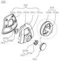
최전방에 스마트폰의 하부 일부를 긴밀히 수용하도록 형성된 스마트폰수용부(111)의 하단 양측에 스마트폰의 양단부를 고정하는 스마트폰유동제어구(112)가 상호 마주보며 위치조절 홀(113)을 따라 위치 조절되게 설치하여 된 스마트폰거치수단(110)이 마련되고, 상기 스마트폰거치수단의 후방 밀폐된 공간(S)의 전방에는 스마트폰의 화면 영상이 통과되는 통과부(120)가 형성되며, 상기 통과부의 후방에는 상기 공간의 상부 전방에서 후방 하부로 40-50° 하향 기울어지는 반사미러(130)가 설치되고, 상기 반사미러의 하부에는 프리넬볼록렌즈(140)가 설치되며, 상기 프리넬볼록렌즈의 하부에는 전방에서 후방으로 하향 기울어지는 전반사미러(150)가 설치되고, 상기 전반사미러에는 빛 차단렌즈(160)가 설치되며, 후방 양측에는 머리의 양측에 지지되는 지지구(170)를 각각 형성시켜 된 본체(100)와,
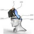
상기 각 지지구의 후단부에 회동부재(210)를 매개로 회동 가능하게 설치되고, 전방에는 착용자의 이마 상부를 감싸며 이마에 의지 되는 의지부재(220)를 설치하여 된 이마의지수단(200)과,
상기 이마의지수단의 양 후단부와 전방이 관절부재(310)를 매개로 각도 전환되게 설치되고, 후방에는 길이를 조절하는 길이조절부재(320)를 설치하여 된 머리의 후방을 감싸는 길이조절밴드(300)로 구성되어The problem solving means configuration of the present invention for achieving the above object is,
The smart phone
The forehead prosthesis means 200, which is installed rotatably at the rear end of each of the supports by means of a
The front and rear ends of the forehead support means are installed so as to be angled through the
상기 스마트폰거치수단, 반사미러, 프리넬볼록렌즈가 설치된 본체가 착용자의 시선 즉 눈 상부에 위치하도록 하여 착용자가 상기 본체의 하중으로 인한 압박감과 착용 자국의 발생을 최소화하도록 형성시켜 된 것으로 이루어진다.The smartphone mounting means, the reflecting mirror, and the Fresnel convex lens are installed so that the body is positioned above the wearer's gaze, that is, above the eyes to minimize the wearer's feeling of pressure due to the load of the body and the occurrence of wear marks.
삭제delete
삭제delete
삭제delete
삭제delete
상기와 같은 구성을 가지는 본 발명의 스마트폰 거치 기능을 갖는 증강현실기기는, 상기 목적에서 설명한 바와 같이 전방에 스마트폰을 거치하고 머리에 작용한 상태에서 상기 스마트폰에서 구현되는 영상을 보며 자유롭게 이동할 수 있음은 물론, 양손을 자유롭게 사용할 수 있고, 또 머리에 착용한 증강현실 기기의 무게에 따른 압박감과 착용부위 자국을 최소화할 수 있는 효과가 있다.The augmented reality device having a smartphone holding function of the present invention having the configuration as described above, as described above, mounts the smartphone in the front and moves freely while viewing the image implemented in the smartphone in a state acting on the head. Of course, it is possible to use both hands freely, and there is an effect of minimizing the pressure and wear marks due to the weight of the augmented reality device worn on the head.
도 1은 종래의 휴대용 증강현실 체험 시스템을 나타낸 개략도,
도 2는 본 발명의 스마트폰 거치 기능을 갖는 증강현실 기기 사시도,
도 3은 본 발명의 스마트폰 거치 기능을 갖는 증강현실 기기 단면도,
도 4는 본 발명의 스마트폰 거치 기능을 갖는 증강현실 기기에서 스마트폰거치수단 발췌 구성도,
도 5는 본 발명의 스마트폰 거치 기능을 갖는 증강현실 기기에서 의지부재 발췌 구성도,
도 6은 본 발명의 스마트폰 거치 기능을 갖는 증강현실 기기에서 길이조절부재의 발췌 분해 사시도,
도 7a 및 도 7b는 은 본 발명의 스마트폰 거치 기능을 갖는 증강현실 기기에서 길이조절부재의 작동상태를 나타낸 단면도,
도 8a 및 도 8b는 은 본 발명의 스마트폰 거치 기능을 갖는 증강현실 기기 사용상태를 나타낸 개략도.1 is a schematic diagram showing a conventional portable augmented reality experience system;
2 is a perspective view of an augmented reality device having a smartphone holding function of the present invention;
3 is a cross-sectional view of an augmented reality device having a smartphone mounting function of the present invention;
4 is an excerpt configuration diagram of a smartphone mounting means in an augmented reality device having a smartphone holding function of the present invention;
5 is a configuration diagram of an extract of a prosthesis member in an augmented reality device having a smartphone holding function of the present invention;
Figure 6 is an excerpted exploded perspective view of the length adjustment member in the augmented reality device having a smartphone mounting function of the present invention;
7a and 7b are cross-sectional views showing the operating state of the length adjustment member in the augmented reality device having a smartphone mounting function of the present invention;
8a and 8b are schematic diagrams showing the use of an augmented reality device having a smartphone holding function of the present invention.
본 발명은 증강현실 기기에 스마트폰을 거치하고 머리에 착용한 상태에서 스마트폰에서 구현되는 영상을 보며 자유롭게 이동할 수 있음은 물론, 머리에 착용 되는 증강현실 기기의 무게에 따른 압박감과 착용부위 자국을 최소화할 수 있도록 한 스마트폰 거치 기능을 갖는 증강현실 기기에 관한 것으로, 이를 첨부도면을 참조하여 실시 예를 설명하면 아래와 같다.The present invention not only allows the user to freely move while viewing the image implemented on the smartphone in a state where the smartphone is mounted on the augmented reality device and worn on the head, but also reduces the pressure and wear part marks according to the weight of the augmented reality device worn on the head. It relates to an augmented reality device having a smartphone holding function that can be minimized, and an embodiment thereof will be described with reference to the accompanying drawings.
- 아 래 -- under -
아래의 설명에서 증상현실(Augmented Reality) 기기의 구성 및 기능은 이미 잘 알려진 것으로, 그에 대한 구체적인 설명은 생략하고, 본 발명의 특징인 스마트폰의 영상이 착용자에게 전달되는 구성 및 증상현실(Augmented Reality) 기기를 착용하고 사용함에 있어 그 사용을 편리하게 할 수 있도록 하는 구성과 그 작용 효과에 대하여 설명한다.In the description below, the configuration and function of the augmented reality device are already well known, and a detailed description thereof will be omitted, and the configuration and augmented reality in which the image of the smartphone, which is a feature of the present invention, is delivered to the wearer. ) In wearing and using the device, the configuration and its effect will be described to make it convenient to use.
본 발명의 스마트폰 거치 기능을 갖는 증강현실 기기는, 도 2 내지 도 8b에 나타낸 바와 같이, 최전방에 스마트폰의 하부 일부를 긴밀히 수용하도록 형성된 스마트폰수용부(111)의 하단 양측에 스마트폰의 양단부를 고정하는 스마트폰유동제어구(112)가 상호 마주보며 위치조절 홀(113)을 따라 위치 조절되게 설치하여 된 스마트폰거치수단(110)이 마련되고, 상기 스마트폰거치수단의 후방 밀폐된 공간(S)의 전방에는 스마트폰의 화면 영상이 통과되는 통과부(120)가 형성되며, 상기 통과부의 후방에는 상기 공간의 상부 전방에서 후방 하부로 40-50° 하향 기울어지는 반사미러(130)가 설치되고, 상기 반사미러의 하부에는 프리넬볼록렌즈(140)가 설치되며, 상기 프리넬볼록렌즈의 하부에는 전방에서 후방으로 하향 기울어지는 전반사미러(150)가 설치되고, 상기 전반사미러에는 빛 차단렌즈(160)가 설치되며, 후방 양측에는 머리의 양측에 지지되는 지지구(170)를 각각 형성시켜 된 본체(100)와,
상기 각 지지구의 후단부에 회동부재(210)를 매개로 회동 가능하게 설치되고, 전방에는 착용자의 이마 상부를 감싸며 이마에 의지 되는 의지부재(220)를 설치하여 된 이마의지수단(200)과,
상기 이마의지수단의 양 후단부와 전방이 관절부재(310)를 매개로 각도 전환되게 설치되고, 후방에는 길이를 조절하는 길이조절부재(320)를 설치하여 된 머리의 후방을 감싸는 길이조절밴드(300)로 구성되어
상기 스마트폰거치수단, 반사미러, 프리넬볼록렌즈가 설치된 본체가 착용자의 시선 즉 눈 상부에 위치하도록 하여 착용자가 상기 본체의 하중으로 인한 압박감과 착용 자국의 발생을 최소화하도록 형성시켜 된 것으로 이루어진다.Augmented reality device having a smartphone holding function of the present invention, as shown in FIGS. 2 to 8b, the lower side of the
The forehead prosthesis means 200, which is installed rotatably at the rear end of each of the supports by means of a
The front and rear ends of the forehead support means are installed so as to be angled through the
The smartphone mounting means, the reflecting mirror, and the Fresnel convex lens are installed so that the body is positioned above the wearer's gaze, that is, above the eyes, so that the wearer feels pressure due to the weight of the body and the occurrence of wear marks is minimized.
삭제delete
삭제delete
삭제delete
상기의 구성에서 최전방에 스마트폰거치수단(110)을 형성시킨 이유는, 스마트폰(P)을 상기 스마트폰거치수단(110)에 안전하고 견고하게 거치시켜 이동중에도 스마트폰(P)이 스마트폰거치수단(110)으로부터 움직이지 않고 안전하게 고정 지지하도록 하기 위함이다.The reason for forming the smart phone mounting means 110 in the front in the above configuration is that the smart phone P is safely and firmly mounted on the smart
또 상기 스마트폰거치수단(110)의 후방 밀폐된 공간(S)의 전방에 스마트폰(P)에서 디스플레이되는 화면 영상을 통과시키는 통과부(120)는, 스마트폰의 화면과 준하거나 그보다 큰 관통 공간이다.In addition, the
그리고 상기 통과부(120)의 후방에는 상기 공간(S)의 상부 전방에서 후방 하부로 40-50° 하향 기울기를 갖도록 반사미러(130)가 설치되는데. 그 이유는, 상기 스마트폰(P)의 영상이 통과부(120)를 통과하며 반사미러(130)로 조사되면 그 조사되는 영상을 하방으로 반사하도록 하기 위함이다.And a
상기와 같이 스마트폰(P)의 영상을 하방으로 반사하는 반사미러(130)의 가장 바람직한 설치각도는 45°이다. 그 이유는 통과부(120)를 통과하며 반사미러(130)로 조사되는 영상을 하방 수직으로 반사하도록 하기 위함이다.As described above, the most preferable installation angle of the
또한, 상기 반사미러(130)의 하부에는 프리넬볼록렌즈(140)가 설치되는데, 그 프리넬볼록렌즈(140)를 설치하는 이유는, 상기 반사미러(130)에서 반사되는 영상을 아래에서 설명되는 전반사미러(150)로 확대하여 전달하도록 하기 위함이다.In addition, a Fresnel convex
상기 전반사미러(150)는, 전반사미러 소재를 코팅하여 된 것으로, 이와 같은 전반사미러(150)는, 증강현실기기를 착용한 착용자의 시선과 준하는 전방의 위치에 위치하도록 형성되고, 이와 같은 전반사미러(150)는 그 전반사미러의 중앙부와 상기 본 발명의 기기를 착용한 착용자의 시선 즉 눈이 도 8a에 나타낸 바와 같이 일치하도록 설치함이 바람직하다.The
그리고 상기 전반사미러재가 코팅된 전반사미러(150)는, 전방에서 후방으로 하향 기울어지도록 설치함이 바람직한데 그 이유는, 본 발명의 기기를 착용한 착용자가 편안하고 선명하게 목측할 수 있도록 하기 위함이다.And the
한편, 상기 전반사미러재가 코팅된 전반사미러(150)는, 빛 차단렌즈(160)에 형성됨이 바람직하고, 그 빛 차단렌즈(160)를 설치하는 이유는, 외부에서 들어오는 빛을 차단하여 상기 전반사미러에서 구현되는 영상을 선명하게 목측할 수 있도록 하기 위함이다.On the other hand, the
또한, 본 발명의 스마트폰거치수단(110)은, 스마트폰(P)의 하부 일부를 긴밀히 수용하는 스마트폰수용부(111)가 도 4에 나타낸 바와 같이 형성되고, 그 마트폰수용부(111)의 하단 양측에는 스마트폰의 유동을 제어하는 스마트폰유동제어구(112)가 위치조절 홀(113)을 따라 위치 조절되게 설치하여 된 것으로 이루어진다.In addition, in the smartphone mounting means 110 of the present invention, the
상기의 구성에서 스마트폰의 유동을 제어하는 스마트폰유동제어구(112)는, 도 4에 나타낸 바와 같이, 스마트폰수용부(111)의 양측에 각각의 스마트폰유동제어구(112)를 상호 마주보도록 설치하고, 이와 같이 설치된 상기 스마트폰유동제어구(112)는, 위치조절 홀(113)을 따라 위치 이동함으로써 스마트폰의 크기에 따라 스마트폰유동제어구(112)의 위치를 조절하여 상기 스마트폰유동제어구(112)가 스마트폰의 양단부를 고정하도록 함으로써 스마트폰의 유동을 제어한다.The smartphone
상기 스마트폰유동제어구(112)의 일실시 예는, 각 스마트폰유동제어구(112) 간에는 탄성스프링을 설치하여 각 스마트폰유동제어구(112) 간의 거리가 멀어지면 탄성스프링의 탄성력에 의해 당김력이 발생되게 함으로서 스마트폰의 양단부를 견고하게 고정하여 스마트폰의 유동을 제어하도록 할 수도 있고, 그 외에도 스마트폰의 양단부분을 견고하게 지지 고정할 수 있는 구성이면 모두 가능하다.In an embodiment of the smartphone
또 상기 본체(100)의 후방 양측에는 도 3에 나타낸 바와 같이 머리의 양측에 지지되는 지지구(170)가 설치되고, 그 지지구(170)에는 상기 이마의지수단(200)을 연결 설치한다.In addition,
상기의 구성에서 스마트폰거치수단(110), 반사미러(130), 프리넬볼록렌즈(140)가 설치된 본체(100)는 도 8a에 나타낸 바와 같이 착용자의 시선 즉 눈 상부에 위치하도록 하고, 그들의 구성에서 발생되는 하중을 착용자의 이마 상부에서 받도록 하여 본 발명의 증강현실기기를 착용한 착용자의 앞면에 상기 본체의 하중으로 인한 압박감과 착용 자국의 발생을 최소화하도록 하였다.In the above configuration, the
상기 본체(100)의 하중이 착용자의 이마 상부에서 받도록 하여 착용자의 앞면에 압박감과 착용 자국 발생을 최소화하는 구성은, 착용자의 이마 상부를 감싸며 이마에 의지 되는 의지부재(220)로써, 그 의지부재(220)의 일실시 예 구성은, 도 5에 나타낸 바와 같이 착용자의 이마 상부를 감싸며 이마에 얹어져 의지 되는 의지구(221)가 형성되고, 그 의지구(221)의 내면에는 이마와의 접촉감을 향상시키는 탄성부재(222)가 설치된다.The configuration that minimizes pressure and wear marks on the wearer's front surface by receiving the load of the
상기의 의지부재(220) 구성에서 의지구(221)는 착용자의 이마 상부를 감싸는 경질의 띠 형태로 이루어지고, 그 띠의 내면에는 쿠션력을 갖는 탄성부재(222)가 설치되며 상기 탄성부재(222)의 표면에는 이마와의 접촉감을 향상시키기 위하여 부드러운 융과 같은 섬유를 코팅하여 사용할 수 있다.In the configuration of the
상기와 같은 의지부재(220)는, 이마의 상부에 지지되어 스마트폰거치수단(110), 반사미러(130), 프리넬볼록렌즈(140)가 설치된 본체(100)의 하중이 이마의 상부에 미치도록 함으로써 안정적으로 의지 되는 것이다.The
이상에서 설명한 본 발명은 상기 지지구(170)에 회동부재(210)를 매개로 회동 가능하게 의지부재(220)가 설치되고, 그 의지부재(220)는 착용자의 이마 상부를 감싸며 이마에 의지 되도록 함으로써 상기 스마트폰거치수단(110), 반사미러(130), 프리넬볼록렌즈(140)가 설치된 본체(100)의 하중이 이마의 상부에 미침으로 본체(100)의 하중으로 인한 착용자의 앞면 압박감과 착용 자국의 발생을 최소화할 수 있는 장점이 있는 것이다.In the present invention described above, the
상기 각 지지구(170)의 후단부에는 의지부재(220)의 후방과 회동부재(210)를 매개로 회동 가능하게 설치하여 본 발명의 기기를 머리에 착용한 상태에서 스마트폰의 영상을 볼 때에는 도 8a에 나타낸 바와 같이 전반사미러(150)와 시선이 일치되도록 본체(100)를 회동시키고, 외부의 환경을 직접 볼 때에는 도 8b에 나타낸 바와 같이 본체(100)를 시선 밖으로 회동시켜 눈으로 외부의 환경을 직접 볼 수 있도록 하면 된다.
본체(100)를 도 8a 및 도 8b에 나타낸 바와 같이 필요에 따라 용이하게 회동할 수 있도록 함으로써 사용상의 편리함을 준다.At the rear end of each
As shown in FIGS. 8A and 8B , the
단 상기의 회동부재(210)는, 다양하게 할 수 있으나, 바람직하게는 본체(100)가 회동 완료 후에 그 회동 완료된 위치로부터 정역방향으로 회동되지 않도록 함이 좋다.However, the
또 본 발명의 관절부재(310)는, 도 3에 나타낸 바와 같이 길이조절밴드(300)의 선단부와 이마의지수단(200) 후단부 간에 각도 조절할 수 있도록 설치되는 것으로, 그 구성은, 상기 길이조절밴드(300)의 선단부와 이마의지수단(200) 후단부 일부를 중첩시킨 후 그 중첩된 부분을 관절부재(310)인 회전 핀을 관통하며 설치하여 된 것으로 이루어진다.In addition, the
따라서 상기 길이조절밴드(300)의 선단부와 이마의지수단(200) 후단부 간의 각도 조절은 상기 관절부재(310)인 회전 핀을 축으로 이루어진다.Accordingly, the angle adjustment between the front end of the
그리고 본 발명의 길이조절부재(320)는, 도 6에 나타낸 바와 같이 중앙에 관통 홀(321a)이 형성되고 하부에 길이조절밴드(300)가 이동하는 가이드 홀(321b)이 형성된 한 쌍의 덮개(321c)로 구성되는 몸체(321)와, 상기 가이드 홀(321b)의 내부에 위치하도록 설치되며, 중앙에 기어(322a)가 형성되고 일 측에 결합부(322b)를 형성시켜 된 길이조절밴드작동구(322)가 설치되고, 그 길이조절밴드작동구의 일 측에는 후방 외주 연에 복수 개의 돌기(323a)가 형성되고 전방에 상기 결합부(322b)와 결합되는 결합구(323b)를 형성시켜 된 동력전달구(323)가 설치되며, 상기 동력전달구의 일 측에는 상기 몸체(321)의 외부로 노출되게 설치되며 내주 면에 상기 돌기(323a)가 결합되는 돌기 홈(324a)이 형성되고 중앙에는 상기 동력전달구(323)와 길이조절밴드작동구(322)를 관통하며 설치되는 축(324b)을 설치하여 된 회전레버(324)로 구성된다.And the
상기의 구성에서 회전레버(324)에 형성된 축(324b)은, 동력전달구(323)와 길이조절밴드작동구(322)를 관통하며 결합되어 일 측의 덮개와 끼워 결합되는 것이다.In the above configuration, the
또 상기 가이드 홀(321b)에는 도 7a 및 도 7b에 나타낸 바와 같이 양측의 길이조절밴드(300) 후방 일부가 상호 방향을 달리하며 관통하고, 그 관통된 양측의 길이조절밴드(300) 후방 일부에 형성된 각각의 장홀(330)은 상기 기어(322a)를 수용하게 되는 것이다.In addition, in the
따라서 길이조절밴드(300)를 조절하고자 회전레버(324)를 일 측으로 회전시키게 되면 일 측의 장 홀 상부 길이 방향으로 형성된 상부기어(330a)는 길이조절밴드작동구(322)의 상부에 위치한 기어(322a)와 결합되고, 타 측의 장 홀 하부 길이 방향으로 형성된 하부기어(330b)는 길이조절밴드작동구(322)의 하부에 위치한 기어(322a)와 결합 되므로 상기 회전레버(324)를 일 측으로 회전시키면 각 길이조절밴드(300)의 이동방향을 서로 달리하며 길이조절밴드(300)의 길이를 짧게 하고, 또 상기 회전레버(324)를 타 측으로 회전시키면 상기 길이조절밴드(300)를 짧게 하는 작동과 역 작동되어 길이조절밴드(300)의 길이를 길게 할 수 있음으로 상기 길이조절밴드(300)를 원하는 만큼 자유롭게 조절할 수 있는 것이다.Therefore, when the
또 상기 돌기(323a)와 돌기 홈(324a)을 형성시켜 돌기(323a)가 돌기 홈(324a)에 결합되게 하는 이유는, 길이조절밴드(300)를 원하는 만큼 조절시키고자 회전레버(324)를 회전시킬 때에 상기 동력전달구(323)와 회전레버(324)가 공회전하지 않도록 하기 위함이다.In addition, the reason why the
이상에서 설명한 바와 같은 본 발명의 스마트폰 거치 기능을 갖는 증강현실기기는, 상기 효과에서 설명한 바와 같이 전방에 스마트폰을 거치하고 머리에 작용한 상태에서 상기 스마트폰에서 구현되는 영상을 보며 자유롭게 이동할 수 있음은 물론, 양손을 자유롭게 사용할 수 있고, 또 머리에 착용한 증강현실 기기의 무게에 따른 압박감과 착용부위 자국을 최소화할 수 있는 장점이 있다.As described above, the augmented reality device having the smartphone holding function of the present invention can move freely while viewing the image implemented in the smartphone while the smartphone is mounted in front and acted on the head as described in the above effect. Of course, it is possible to freely use both hands, and it has the advantage of minimizing the pressure and the wear part marks due to the weight of the augmented reality device worn on the head.
100 : 본체 110 : 스마트폰거치수단
111 : 스마트폰수용부 112 : 스마트폰유동제어구
120 : 통과부 130 : 반사미러
140 : 프리넬볼록렌즈 150 : 전반사미러
160 : 빛 차단렌즈 170 : 지지구
200 : 이마의지수단 210 : 회동부재
220 : 의지부재 221 : 의지구
222 : 탄성부재 300 : 길이조절밴드
310 : 관절부재
320 : 길이조절부재 321 : 몸체
321a : 관통 홀 321b : 가이드 홀
321c : 덮개 322 : 길이조절밴드작동구
322a : 기어 322b : 결합부
323 : 동력전달구 323a : 돌기
323b : 결합부 324 : 회전레버
324a : 돌기 홈 324b : 축100: body 110: smartphone mounting means
111: smartphone accommodating part 112: smartphone flow control device
120: passing part 130: reflecting mirror
140: Fresnel convex lens 150: total reflection mirror
160: light blocking lens 170: support
200: forehead support means 210: rotation member
220: absence of will 221: earth of will
222: elastic member 300: length adjustment band
310: joint member
320: length adjustment member 321: body
321a: through
321c: cover 322: length adjustment band operating member
322a:
323:
323b: coupling part 324: rotary lever
324a:
Claims (6)
Translated fromKorean상기 각 지지구의 후단부에 회동부재(210)를 매개로 회동 가능하게 설치되고, 전방에는 착용자의 이마 상부를 감싸며 이마에 의지 되는 의지부재(220)를 설치하여 된 이마의지수단(200)과,
상기 이마의지수단의 양 후단부와 전방이 관절부재(310)를 매개로 각도 전환되게 설치되고, 후방에는 길이를 조절하는 길이조절부재(320)를 설치하여 된 머리의 후방을 감싸는 길이조절밴드(300)로 구성되어
상기 스마트폰거치수단, 반사미러, 프리넬볼록렌즈가 설치된 본체가 착용자의 시선 즉 눈 상부에 위치하도록 하여 착용자가 상기 본체의 하중으로 인한 압박감과 착용 자국의 발생을 최소화하도록 형성시켜 된 것을 특징으로 하는 스마트폰 거치 기능을 갖는 증강현실 기기.
The smart phone flow control tool 112 for fixing both ends of the smart phone on both lower sides of the lower end of the smart phone accommodating part 111 formed to closely accommodate the lower part of the smart phone at the forefront faces each other and along the positioning hole 113 A smartphone mounting means 110 installed so as to be adjusted in position is provided, and a passing part 120 through which the screen image of the smartphone passes is formed in front of the rear sealed space S of the smartphone mounting means, A reflecting mirror 130 inclined downward by 40-50° from the upper front of the space to the rear lower part is installed at the rear of the passing part, and a Fresnel convex lens 140 is installed in the lower part of the reflecting mirror, and the Fresnel A total reflection mirror 150 inclined downward from the front to the rear is installed in the lower part of the convex lens, a light blocking lens 160 is installed in the total reflection mirror, and a support unit 170 supported on both sides of the head is provided on both sides of the rear side. A body 100 formed by forming each, and
The forehead prosthesis means 200, which is installed rotatably at the rear end of each of the supports by means of a rotation member 210, and in the front, a prosthetic member 220 that wraps around the upper part of the wearer's forehead and leans on the forehead;
The front and rear ends of the forehead support means are installed so as to be angled through the joint member 310, and a length adjustment member 320 for adjusting the length is installed at the rear of the length adjustment band surrounding the back of the head ( 300) consists of
It is characterized in that the main body in which the smartphone mounting means, the reflective mirror, and the Fresnel convex lens are installed is positioned above the wearer's gaze, that is, the upper part of the eyes to minimize the wearer's feeling of pressure due to the weight of the main body and the occurrence of wear marks. Augmented reality device with smartphone holding function.
상기 스마트폰거치수단(110), 반사미러(130), 프리넬볼록렌즈(140)가 설치되는 본체(100) 부분은, 증강현실기기를 착용한 착용자의 눈 상부에 위치하도록 하여 상기 본체의 하중을 착용자의 이마 상부에서 받도록 구성시켜 된 것을 특징으로 하는 스마트폰 거치 기능을 갖는 증강현실 기기.
According to claim 1,
The smartphone mounting means 110, the reflective mirror 130, and the main body 100 where the Fresnel convex lens 140 are installed is placed on the upper part of the eye of the wearer who wears the augmented reality device, so that the load of the main body Augmented reality device having a smartphone mounting function, characterized in that configured to receive the upper forehead of the wearer.
상기 길이조절부재(320)는, 중앙에 관통 홀(321a)이 형성되고 하부에 길이조절밴드(300)가 이동하는 가이드 홀(321b)이 형성된 한 쌍의 덮개(321c)로 구성되는 몸체(321)와, 상기 가이드 홀(321b)의 내부에 위치하도록 설치되며, 중앙에 기어(322a)가 형성되고 일 측에 결합부(322b)를 형성시켜 된 길이조절밴드작동구(322)가 설치되며, 그 길이조절밴드작동구의 일 측에는 후방 외주 연에 복수 개의 돌기(323a)가 형성되고 전방에는 상기 결합부(322b)와 결합되는 결합구(323b)를 형성시켜 된 동력전달구(323)가 설치되고, 상기 동력전달구의 일 측에는 상기 몸체(321)의 외부로 노출되게 설치되며 내주 면에 상기 돌기(323a)가 결합되는 돌기 홈(324a)이 형성되고 중앙에는 상기 동력전달구(323)와 길이조절밴드작동구(322)를 관통하며 일 측의 덮개에 끼워 고정되는 축(324b)을 형성시켜 된 회전레버(324)로 구성된 것을 특징으로 하는 스마트폰 거치 기능을 갖는 증강현실 기기.
According to claim 1,
The length adjustment member 320 is a body 321 comprising a pair of covers 321c having a through hole 321a formed in the center and a guide hole 321b at the lower portion through which the length adjustment band 300 moves. ), and is installed to be located inside the guide hole 321b, a gear 322a is formed in the center, and a length adjustment band operating tool 322 formed by forming a coupling part 322b on one side is installed, A plurality of protrusions 323a are formed on one side of the length adjustment band actuating member on the rear outer periphery, and a power transmission port 323 formed by forming a coupling member 323b coupled to the coupling part 322b in the front is installed, and , The power transmission hole is installed to be exposed to the outside of the body 321 on one side of the protrusion groove 324a is formed on the inner peripheral surface to which the projection 323a is coupled, and the power transmission hole 323 and length adjustment in the center Augmented reality device having a smartphone mounting function, characterized in that it is composed of a rotary lever (324) formed by forming a shaft (324b) that passes through the band operation member (322) and is fixed to the cover on one side.
상기 길이조절부재(320)에 형성된 가이드 홀(321b)에는, 양측의 길이조절밴드(300) 후방 일부가 상호 방향을 달리하며 관통 설치되고, 그 관통 설치된 상기 양측의 길이조절밴드 후방에는 각각의 장홀(330)이 형성되며, 상기 각 장홀 중 어느 한쪽의 장홀 상부 길이 방향으로는 길이조절밴드작동구(322)에 형성된 기어(322a)와 결합되는 상부기어(330a)가 형성되고, 다른 한쪽의 장홀 하부 길이 방향으로는 상기 기어(322a)와 결합되는 하부기어(330b)를 형성시켜 된 것을 특징으로 하는 스마트폰 거치 기능을 갖는 증강현실 기기.According to claim 1,
In the guide hole 321b formed in the length adjustment member 320, the rear portions of the length adjustment bands 300 on both sides are installed through each other in different directions, and each long hole is provided in the rear of the length adjustment bands on both sides installed through the guide hole 321b. 330 is formed, and in the longitudinal direction of one of the long holes, an upper gear (330a) coupled to the gear (322a) formed in the length adjustment band operation member 322 is formed, and the other long hole is formed. Augmented reality device having a smartphone mounting function, characterized in that by forming a lower gear (330b) coupled to the gear (322a) in the lower longitudinal direction.
Priority Applications (1)
| Application Number | Priority Date | Filing Date | Title |
|---|---|---|---|
| KR1020190149606AKR102353037B1 (en) | 2019-11-20 | 2019-11-20 | Augmented Reality Device Stationary Smart Phone |
Applications Claiming Priority (1)
| Application Number | Priority Date | Filing Date | Title |
|---|---|---|---|
| KR1020190149606AKR102353037B1 (en) | 2019-11-20 | 2019-11-20 | Augmented Reality Device Stationary Smart Phone |
Publications (2)
| Publication Number | Publication Date |
|---|---|
| KR20210061727A KR20210061727A (en) | 2021-05-28 |
| KR102353037B1true KR102353037B1 (en) | 2022-01-19 |
Family
ID=76140564
Family Applications (1)
| Application Number | Title | Priority Date | Filing Date |
|---|---|---|---|
| KR1020190149606AActiveKR102353037B1 (en) | 2019-11-20 | 2019-11-20 | Augmented Reality Device Stationary Smart Phone |
Country Status (1)
| Country | Link |
|---|---|
| KR (1) | KR102353037B1 (en) |
Families Citing this family (1)
| Publication number | Priority date | Publication date | Assignee | Title |
|---|---|---|---|---|
| TWM622202U (en)* | 2021-09-08 | 2022-01-11 | 怡利電子工業股份有限公司 | Head mounted fixing device |
Citations (1)
| Publication number | Priority date | Publication date | Assignee | Title |
|---|---|---|---|---|
| JP2018129692A (en)* | 2017-02-08 | 2018-08-16 | 株式会社バンダイナムコエンターテインメント | Head mounted display device and simulation system |
Family Cites Families (8)
| Publication number | Priority date | Publication date | Assignee | Title |
|---|---|---|---|---|
| KR20170055908A (en)* | 2015-11-12 | 2017-05-22 | 최해용 | Cap type virtual reality display image system |
| KR101835874B1 (en)* | 2015-12-15 | 2018-03-13 | 박석봉 | Head-mounted apparatus for mobile terminal |
| US10963009B2 (en)* | 2016-10-18 | 2021-03-30 | Lg Electronics Inc. | Head-mounted display |
| KR102075383B1 (en) | 2016-11-24 | 2020-02-12 | 한국전자통신연구원 | Augmented reality system linked to smart device |
| KR102482756B1 (en)* | 2017-06-14 | 2022-12-30 | 삼성전자주식회사 | Head-mounted display apparatus |
| CN107656382B (en) | 2017-10-19 | 2019-12-27 | 歌尔科技有限公司 | Augmented reality glasses |
| KR102001546B1 (en) | 2017-10-26 | 2019-07-17 | 주식회사 미디어프론트 | Portable Augmented Reality Experience System |
| KR20190087061A (en)* | 2018-01-16 | 2019-07-24 | 주식회사 씨에스위모 | Head mounted display device for a smart phone |
- 2019
- 2019-11-20KRKR1020190149606Apatent/KR102353037B1/enactiveActive
Patent Citations (1)
| Publication number | Priority date | Publication date | Assignee | Title |
|---|---|---|---|---|
| JP2018129692A (en)* | 2017-02-08 | 2018-08-16 | 株式会社バンダイナムコエンターテインメント | Head mounted display device and simulation system |
Also Published As
| Publication number | Publication date |
|---|---|
| KR20210061727A (en) | 2021-05-28 |
Similar Documents
| Publication | Publication Date | Title |
|---|---|---|
| US10324295B2 (en) | Eyeglass-type display apparatus | |
| US6563626B1 (en) | Display device | |
| US5971538A (en) | Articulated nose bridge for head mounted display | |
| US20040252077A1 (en) | Display | |
| US10732418B2 (en) | Wearable device | |
| EP2066119A1 (en) | Head-mount type display unit, and image display unit | |
| JP2017068045A (en) | Wearable device | |
| KR20020010078A (en) | Compact optical system and packaging for head mounted display | |
| KR102353037B1 (en) | Augmented Reality Device Stationary Smart Phone | |
| KR101875313B1 (en) | Head mounted display with lens controller | |
| KR102078491B1 (en) | Head mounted display unit | |
| KR101550734B1 (en) | Medical Loupe | |
| JP2010124339A (en) | Head-mounted display | |
| KR101835874B1 (en) | Head-mounted apparatus for mobile terminal | |
| US11022807B2 (en) | Electronic eye wear viewing device | |
| CN114967157A (en) | AR glasses with adjustable it is multi-functional | |
| KR20230040066A (en) | Head-mounted display apparatus with one-button automatic size adjustment | |
| KR102823347B1 (en) | Ar glasses apparatus with automatic adjustable virtual image distance | |
| CN108076195B (en) | Augmented reality mobile phone box for realizing video perspective | |
| JP4258950B2 (en) | Video display device | |
| KR102617019B1 (en) | Head-mounted display apparatus that adjusts the inter-pupillary distance by moving the binocular lenses simultaneously with rack and pinion | |
| EP3646111A1 (en) | Eyeglass frame | |
| JPH07270715A (en) | Visual display device | |
| JP6421558B2 (en) | Image display device | |
| KR20220077000A (en) | Augmented Re|ality Instrument for Education |
Legal Events
| Date | Code | Title | Description |
|---|---|---|---|
| PA0109 | Patent application | St.27 status event code:A-0-1-A10-A12-nap-PA0109 | |
| PA0201 | Request for examination | St.27 status event code:A-1-2-D10-D11-exm-PA0201 | |
| R18-X000 | Changes to party contact information recorded | St.27 status event code:A-3-3-R10-R18-oth-X000 | |
| R18-X000 | Changes to party contact information recorded | St.27 status event code:A-3-3-R10-R18-oth-X000 | |
| D13-X000 | Search requested | St.27 status event code:A-1-2-D10-D13-srh-X000 | |
| D14-X000 | Search report completed | St.27 status event code:A-1-2-D10-D14-srh-X000 | |
| PE0902 | Notice of grounds for rejection | St.27 status event code:A-1-2-D10-D21-exm-PE0902 | |
| E13-X000 | Pre-grant limitation requested | St.27 status event code:A-2-3-E10-E13-lim-X000 | |
| P11-X000 | Amendment of application requested | St.27 status event code:A-2-2-P10-P11-nap-X000 | |
| P13-X000 | Application amended | St.27 status event code:A-2-2-P10-P13-nap-X000 | |
| PG1501 | Laying open of application | St.27 status event code:A-1-1-Q10-Q12-nap-PG1501 | |
| E701 | Decision to grant or registration of patent right | ||
| PE0701 | Decision of registration | St.27 status event code:A-1-2-D10-D22-exm-PE0701 | |
| PR0701 | Registration of establishment | St.27 status event code:A-2-4-F10-F11-exm-PR0701 | |
| PR1002 | Payment of registration fee | St.27 status event code:A-2-2-U10-U11-oth-PR1002 Fee payment year number:1 | |
| PG1601 | Publication of registration | St.27 status event code:A-4-4-Q10-Q13-nap-PG1601 | |
| R18-X000 | Changes to party contact information recorded | St.27 status event code:A-5-5-R10-R18-oth-X000 | |
| R18-X000 | Changes to party contact information recorded | St.27 status event code:A-5-5-R10-R18-oth-X000 | |
| R18-X000 | Changes to party contact information recorded | St.27 status event code:A-5-5-R10-R18-oth-X000 | |
| R18-X000 | Changes to party contact information recorded | St.27 status event code:A-5-5-R10-R18-oth-X000 | |
| R18-X000 | Changes to party contact information recorded | St.27 status event code:A-5-5-R10-R18-oth-X000 | |
| R18-X000 | Changes to party contact information recorded | St.27 status event code:A-5-5-R10-R18-oth-X000 |