KR102352194B1 - Frequency spacing to prevent intermodulation distortion signal interference - Google Patents
Frequency spacing to prevent intermodulation distortion signal interferenceDownload PDFInfo
- Publication number
- KR102352194B1 KR102352194B1KR1020207000205AKR20207000205AKR102352194B1KR 102352194 B1KR102352194 B1KR 102352194B1KR 1020207000205 AKR1020207000205 AKR 1020207000205AKR 20207000205 AKR20207000205 AKR 20207000205AKR 102352194 B1KR102352194 B1KR 102352194B1
- Authority
- KR
- South Korea
- Prior art keywords
- signal
- frequency
- intermodulation distortion
- sensor assembly
- determining
- Prior art date
- Legal status (The legal status is an assumption and is not a legal conclusion. Google has not performed a legal analysis and makes no representation as to the accuracy of the status listed.)
- Active
Links
Images


Classifications
- G—PHYSICS
- G01—MEASURING; TESTING
- G01F—MEASURING VOLUME, VOLUME FLOW, MASS FLOW OR LIQUID LEVEL; METERING BY VOLUME
- G01F1/00—Measuring the volume flow or mass flow of fluid or fluent solid material wherein the fluid passes through a meter in a continuous flow
- G01F1/76—Devices for measuring mass flow of a fluid or a fluent solid material
- G01F1/78—Direct mass flowmeters
- G01F1/80—Direct mass flowmeters operating by measuring pressure, force, momentum, or frequency of a fluid flow to which a rotational movement has been imparted
- G01F1/84—Coriolis or gyroscopic mass flowmeters
- G01F1/8409—Coriolis or gyroscopic mass flowmeters constructional details
- G01F1/8436—Coriolis or gyroscopic mass flowmeters constructional details signal processing
- G—PHYSICS
- G01—MEASURING; TESTING
- G01F—MEASURING VOLUME, VOLUME FLOW, MASS FLOW OR LIQUID LEVEL; METERING BY VOLUME
- G01F1/00—Measuring the volume flow or mass flow of fluid or fluent solid material wherein the fluid passes through a meter in a continuous flow
- G01F1/76—Devices for measuring mass flow of a fluid or a fluent solid material
- G01F1/78—Direct mass flowmeters
- G01F1/80—Direct mass flowmeters operating by measuring pressure, force, momentum, or frequency of a fluid flow to which a rotational movement has been imparted
- G01F1/84—Coriolis or gyroscopic mass flowmeters
- G—PHYSICS
- G01—MEASURING; TESTING
- G01F—MEASURING VOLUME, VOLUME FLOW, MASS FLOW OR LIQUID LEVEL; METERING BY VOLUME
- G01F25/00—Testing or calibration of apparatus for measuring volume, volume flow or liquid level or for metering by volume
- G01F25/10—Testing or calibration of apparatus for measuring volume, volume flow or liquid level or for metering by volume of flowmeters
- G—PHYSICS
- G01—MEASURING; TESTING
- G01R—MEASURING ELECTRIC VARIABLES; MEASURING MAGNETIC VARIABLES
- G01R23/00—Arrangements for measuring frequencies; Arrangements for analysing frequency spectra
- G—PHYSICS
- G01—MEASURING; TESTING
- G01R—MEASURING ELECTRIC VARIABLES; MEASURING MAGNETIC VARIABLES
- G01R23/00—Arrangements for measuring frequencies; Arrangements for analysing frequency spectra
- G01R23/16—Spectrum analysis; Fourier analysis
- G—PHYSICS
- G01—MEASURING; TESTING
- G01R—MEASURING ELECTRIC VARIABLES; MEASURING MAGNETIC VARIABLES
- G01R23/00—Arrangements for measuring frequencies; Arrangements for analysing frequency spectra
- G01R23/16—Spectrum analysis; Fourier analysis
- G01R23/20—Measurement of non-linear distortion
- G—PHYSICS
- G01—MEASURING; TESTING
- G01R—MEASURING ELECTRIC VARIABLES; MEASURING MAGNETIC VARIABLES
- G01R27/00—Arrangements for measuring resistance, reactance, impedance, or electric characteristics derived therefrom
- G01R27/28—Measuring attenuation, gain, phase shift or derived characteristics of electric four pole networks, i.e. two-port networks; Measuring transient response
- G01R27/32—Measuring attenuation, gain, phase shift or derived characteristics of electric four pole networks, i.e. two-port networks; Measuring transient response in circuits having distributed constants, e.g. having very long conductors or involving high frequencies
- G—PHYSICS
- G01—MEASURING; TESTING
- G01R—MEASURING ELECTRIC VARIABLES; MEASURING MAGNETIC VARIABLES
- G01R29/00—Arrangements for measuring or indicating electric quantities not covered by groups G01R19/00 - G01R27/00
- G01R29/06—Measuring depth of modulation
- G—PHYSICS
- G01—MEASURING; TESTING
- G01R—MEASURING ELECTRIC VARIABLES; MEASURING MAGNETIC VARIABLES
- G01R29/00—Arrangements for measuring or indicating electric quantities not covered by groups G01R19/00 - G01R27/00
- G01R29/26—Measuring noise figure; Measuring signal-to-noise ratio
- H—ELECTRICITY
- H04—ELECTRIC COMMUNICATION TECHNIQUE
- H04B—TRANSMISSION
- H04B17/00—Monitoring; Testing
- H04B17/20—Monitoring; Testing of receivers
- H—ELECTRICITY
- H04—ELECTRIC COMMUNICATION TECHNIQUE
- H04B—TRANSMISSION
- H04B3/00—Line transmission systems
- H04B3/02—Details
- H04B3/46—Monitoring; Testing
Landscapes
- Physics & Mathematics (AREA)
- General Physics & Mathematics (AREA)
- Fluid Mechanics (AREA)
- Engineering & Computer Science (AREA)
- Signal Processing (AREA)
- Mathematical Physics (AREA)
- Nonlinear Science (AREA)
- Measuring Volume Flow (AREA)
- Measurement Of Mechanical Vibrations Or Ultrasonic Waves (AREA)
Abstract
Translated fromKorean
Description
Translated fromKorean아래에 설명되는 실시예들은 상호변조 왜곡에 관한 것이며, 더 상세하게는, 상호변조 왜곡 신호 간섭을 방지하기 위한 주파수 간격들에 관한 것이다.The embodiments described below relate to intermodulation distortion and, more particularly, to frequency intervals for preventing intermodulation distortion signal interference.
예컨대, 코리올리 질량 유량계들(Coriolis mass flowmeters), 액체 밀도계들, 가스 밀도계들, 액체 점도계들, 가스/액체 비중계들(gas/liquid specific gravity meters), 가스/액체 상대 밀도계들, 및 가스 분자량 계측기들(gas molecular weight meters)와 같은 진동계들(vibrating meters)은 일반적으로 알려져 있고, 유체들의 특징들을 측정하는 데 사용된다. 일반적으로, 계측기들은 센서 조립체 및 전자 부품을 포함한다. 센서 조립체 내의 물질은 유동하거나 고정적일 수 있다. 각각의 타입의 센서는, 최적의 성능을 달성하기 위해 계측기가 고려해야 하는 고유한 특징들을 가질 수 있다. 예컨대, 일부 센서들은 특정 변위 레벨들에서 진동하도록 튜브 장치에 요구할 수 있다. 다른 센서 조립체 타입들은 특수 보상 알고리즘들을 요구할 수 있다.For example, Coriolis mass flowmeters, liquid density meters, gas density meters, liquid viscometers, gas/liquid specific gravity meters, gas/liquid relative density meters, and gas Vibrating meters, such as gas molecular weight meters, are generally known and used to measure properties of fluids. In general, instruments include a sensor assembly and an electronic component. The material within the sensor assembly may be flowing or stationary. Each type of sensor may have unique characteristics that the instrument must consider to achieve optimal performance. For example, some sensors may require a tube arrangement to vibrate at certain levels of displacement. Other sensor assembly types may require special compensation algorithms.
계측 전자장치는, 다른 기능들을 수행하는 중에서도, 전형적으로 사용되는 특정 센서에 대한 저장된 센서 교정 값들을 포함한다. 예컨대, 계측 전자장치는 기준 센서 강성(stiffness) 측정을 포함할 수 있다. 기준 센서 강성은 기준 조건들 하에서 공장에서 측정된, 특정 센서 조립체에 대한 센서 기하학적 구조에 관련된 기본 측정을 나타낸다. 진동 엘리먼트 계측기가 고객 사이트에 설치된 후 측정된 센서 강성과 기준 센서 강성 사이의 변화는, 다른 원인들 이외에, 센서 조립체의 도관들에 대한 코팅, 침식, 부식 또는 손상으로 인한 센서 조립체의 물리적 변화를 나타낼 수 있다. 계측 검증 또는 건강 체크 테스트는 이러한 변화들을 검출할 수 있다.The metrology electronics, while performing other functions, typically include stored sensor calibration values for a particular sensor being used. For example, the metrology electronics may include a reference sensor stiffness measurement. Reference sensor stiffness represents a basic measurement related to the sensor geometry for a particular sensor assembly, measured at the factory under reference conditions. A change between the measured sensor stiffness and the reference sensor stiffness after the vibrating element meter is installed at the customer site is indicative of a physical change in the sensor assembly due to coating, erosion, corrosion, or damage to the conduits of the sensor assembly, among other causes. can A metrology verification or health check test can detect these changes.
계측 검증은 전형적으로, 센서 조립체의 구동기에 인가되는 멀티-사인(multi-sine), 멀티컴포넌트 등으로 또한 지칭될 수 있는 멀티-톤 구동 신호를 사용하여 수행된다. 멀티-톤 구동 신호는 전형적으로 센서 조립체의 공진 주파수에 있는 공진 컴포넌트 또는 구동 톤, 및 구동 톤으로부터 주파수 간격만큼 이격된 복수의 비-공진 컴포넌트들, 또는 테스트 톤들로 구성된다. 이는, 다수의 테스트 톤들이 순차적으로 순환되는 접근법과 별개이다. 테스트 톤들의 순차적인 순환에서, 시스템의 임의의 시간-변화(예컨대, 온도-의존 영향들, 유동의 변화들)는 센서 조립체의 주파수 응답 특징을 손상시킬 수 있다. 멀티-톤 구동 신호는, 샘플링된 데이터가 동시에 획득되기 때문에 유리하다.Metrology verification is typically performed using a multi-tone drive signal, which may also be referred to as a multi-sine, multicomponent, or the like, applied to an actuator of a sensor assembly. A multi-tone drive signal typically consists of a resonant component or drive tone at the resonant frequency of the sensor assembly, and a plurality of non-resonant components, or test tones, spaced a frequency interval from the drive tone. This is separate from an approach in which multiple test tones are cycled sequentially. In a sequential cycle of test tones, any time-change (eg, temperature-dependent effects, changes in flow) of the system can impair the frequency response characteristic of the sensor assembly. A multi-tone drive signal is advantageous because the sampled data is acquired simultaneously.
멀티-톤 구동 신호의 각각의 테스트 톤은 센서 조립체의 주파수 응답에 대한 입력이다. 센서 조립체에 의해 제공되는 응답 신호의 컴포넌트들은 주파수 응답 함수의 출력들이다. 이러한 컴포넌트들은 센서 조립체의 주파수 응답을 특징화하기 위해 대응하는 테스트 톤들과 비교된다. 센서 조립체에 대해 코팅, 침식, 부식 또는 손상이 발생하면, 센서 조립체의 주파수 응답이 변할 것이다. 그러나, 센서 조립체의 비-선형성들은 멀티-톤 구동 신호로부터 상호변조 왜곡 신호들을 형성할 수 있다.Each test tone of the multi-tone drive signal is an input to the frequency response of the sensor assembly. The components of the response signal provided by the sensor assembly are the outputs of the frequency response function. These components are compared to corresponding test tones to characterize the frequency response of the sensor assembly. If coating, erosion, corrosion or damage occurs to the sensor assembly, the frequency response of the sensor assembly will change. However, non-linearities in the sensor assembly can form intermodulation distortion signals from the multi-tone drive signal.
상호변조 왜곡 신호들은, 센서 조립체에 대한 어떠한 근본적인 변화들도 없이 센서 조립체의 주파수 응답이 변하게 할 수 있다. 더 구체적으로, 멀티-톤 구동 신호의 구동 및 테스트 톤들은, 테스트 톤들 중 하나의 주파수에 있거나 해당 주파수를 중심으로 할 수 있는 주파수들을 갖는 상호변조 왜곡 신호들을 유도할 수 있다. 결과적으로, 상호변조 왜곡 신호에 대응하는 컴포넌트는 테스트 톤들 중 하나에 대응하는 컴포넌트를 간섭할 수 있다. 이 간섭은 주파수 응답 특징을 부정확하게 할 수 있다. 따라서, 상호변조 왜곡 신호 간섭을 방지할 필요가 있다.Intermodulation distortion signals may cause the frequency response of the sensor assembly to change without any fundamental changes to the sensor assembly. More specifically, the drive and test tones of the multi-tone drive signal may induce intermodulation distortion signals having frequencies that may be at or centered at the frequency of one of the test tones. Consequently, the component corresponding to the intermodulation distortion signal may interfere with the component corresponding to one of the test tones. This interference can lead to inaccurate frequency response characteristics. Therefore, there is a need to prevent intermodulation distortion signal interference.
상호변조 왜곡 신호 간섭을 방지하기 위한 주파수 간격들을 결정하기 위한 시스템(800)이 제공된다. 실시예에 따라, 시스템(800)은 센서 조립체(810) 및 센서 조립체(810)에 통신 가능하게 커플링된 계측 검증 모듈(820)을 포함한다. 계측 검증 모듈(820)은 진동계의 센서 조립체(810)에 인가될 제1 신호의 주파수를 결정하고, 제1 신호의 주파수에 관한 복조 윈도우를 설정하도록 구성된다. 계측 검증 모듈(820)은 또한, 제1 신호 및 센서 조립체에 인가될 제2 신호에 의해 생성된 상호변조 왜곡 신호의 주파수가 복조 윈도우 외부에 있도록, 제2 신호의 주파수를 결정하도록 구성된다.A system (800) is provided for determining frequency intervals for preventing intermodulation distortion signal interference. According to an embodiment, the
상호변조 왜곡 신호 간섭을 방지하기 위한 주파수 간격들을 결정하는 방법이 제공된다. 실시예에 따라, 방법은 진동계의 센서 조립체에 인가될 제1 신호의 주파수를 결정하는 단계, 제1 신호의 주파수에 관한 복조 윈도우를 설정하는 단계, 및 제1 신호 및 센서 조립체에 인가될 제2 신호에 의해 생성된 상호변조 왜곡 신호의 주파수가 복조 윈도우 외부에 있도록, 제2 신호의 주파수를 결정하는 단계를 포함한다.A method of determining frequency intervals for preventing intermodulation distortion signal interference is provided. According to an embodiment, a method includes determining a frequency of a first signal to be applied to a sensor assembly of a vibration field, setting a demodulation window with respect to the frequency of the first signal, and a second signal to be applied to the first signal and the sensor assembly. determining the frequency of the second signal such that the frequency of the intermodulation distortion signal generated by the signal is outside the demodulation window.
양상들aspects
양상에 따라, 상호변조 왜곡 신호 간섭을 방지하기 위한 주파수 간격들을 결정하기 위한 시스템(800)은 센서 조립체(810) 및 센서 조립체(810)에 통신 가능하게 커플링된 계측 검증 모듈(820)을 포함한다. 계측 검증 모듈(820)은 진동계의 센서 조립체(810)에 인가될 제1 신호의 주파수를 결정하고, 제1 신호의 주파수에 관한 복조 윈도우를 설정하고, 그리고 제1 신호 및 센서 조립체에 인가될 제2 신호에 의해 생성된 상호변조 왜곡 신호의 주파수가 복조 윈도우 외부에 있도록, 제2 신호의 주파수를 결정하도록 구성된다.According to an aspect, a
바람직하게는, 계측 검증 모듈(820)은 제1 신호의 주파수를 포함하는 대역폭을 결정하고, 그리고 제2 신호의 주파수가 제1 신호의 주파수를 포함하는 대역폭 내에 있도록 제2 신호의 주파수를 결정하도록 추가로 구성된다.Preferably, the
바람직하게는, 대역폭은 센서 조립체의 주파수 응답 대역폭이다.Preferably, the bandwidth is the frequency response bandwidth of the sensor assembly.
바람직하게는, 제1 신호의 주파수는 센서 조립체의 공진 주파수이다.Preferably, the frequency of the first signal is a resonant frequency of the sensor assembly.
바람직하게는, 상호변조 왜곡 신호는 계측 검증 모듈(820) 및 센서 조립체(810) 중 하나에서 생성된다.Preferably, the intermodulation distortion signal is generated in one of the
바람직하게는, 제1 신호 및 제2 신호는, 계측 검증 모듈(820)에 의해 센서 조립체(810)에 인가된 구동 신호의 컴포넌트들이다.Preferably, the first signal and the second signal are components of a drive signal applied to the
바람직하게는, 제2 신호는 센서 조립체(810)의 주파수 응답을 특징화하기 위해 센서 조립체(810)에 인가된다.Preferably, the second signal is applied to the
바람직하게는, 제1 신호 및 센서 조립체(810)에 인가될 제2 신호에 의해 생성된 상호변조 왜곡 신호의 주파수가 복조 윈도우 외부에 있도록 제2 신호의 주파수를 결정하도록 구성된 계측 검증 모듈(820)은, 상호변조 왜곡이 복조 윈도우에 근접하도록 제2 신호의 주파수를 결정하도록 구성된 계측 검증 모듈(820)을 포함한다.Preferably,
바람직하게는, 계측 검증 모듈(820)은, 하나 이상의 추가적인 신호들에 의해 생성된 복수의 상호변조 왜곡 신호들의 주파수들이 제1 신호의 복조 윈도우 외부에 놓이도록 하나 이상의 추가적인 신호들의 주파수를 결정하도록 추가로 구성된다.Preferably,
바람직하게는, 계측 검증 모듈(820)은 제1 신호의 주파수를 포함하는 대역폭을 결정하고, 그리고 하나 이상의 추가적인 신호들의 주파수들이 제1 신호의 주파수를 포함하는 대역폭 내에 있도록 하나 이상의 추가적인 신호들의 주파수들을 결정하도록 추가로 구성된다.Preferably,
바람직하게는, 계측 검증 모듈(820)은, 하나 이상의 추가적인 신호들에 관한 복조 윈도우들을 설정하고, 하나 이상의 추가적인 신호들에 의해 생성된 복수의 상호변조 왜곡 신호들의 주파수들이 하나 이상의 추가적인 신호들의 복조 윈도우들 외부에 놓이도록 하나 이상의 추가적인 신호들의 주파수들을 결정하도록 추가로 구성된다.Preferably,
양상에 따라, 상호변조 왜곡 신호 간섭을 방지하기 위한 주파수 간격들을 결정하는 방법은 진동계의 센서 조립체에 인가될 제1 신호의 주파수를 결정하는 단계, 제1 신호의 주파수에 관한 복조 윈도우를 설정하는 단계, 및 제1 신호 및 센서 조립체에 인가될 제2 신호에 의해 생성된 상호변조 왜곡 신호의 주파수가 복조 윈도우 외부에 있도록, 제2 신호의 주파수를 결정하는 단계를 포함한다.According to an aspect, a method of determining frequency intervals for preventing intermodulation distortion signal interference comprises: determining a frequency of a first signal to be applied to a sensor assembly of a vibration system; setting a demodulation window with respect to the frequency of the first signal; , and determining a frequency of the second signal such that a frequency of the intermodulation distortion signal generated by the first signal and the second signal to be applied to the sensor assembly is outside the demodulation window.
바람직하게는, 방법은 제1 신호의 주파수를 포함하는 대역폭을 결정하는 단계, 및 제2 신호의 주파수가 제1 신호의 주파수를 포함하는 대역폭 내에 있도록 제2 신호의 주파수를 결정하는 단계를 더 포함한다.Advantageously, the method further comprises determining a bandwidth comprising a frequency of the first signal, and determining a frequency of the second signal such that the frequency of the second signal is within a bandwidth comprising the frequency of the first signal. do.
바람직하게는, 대역폭은 센서 조립체의 주파수 응답 대역폭이다.Preferably, the bandwidth is the frequency response bandwidth of the sensor assembly.
바람직하게는, 제1 신호의 주파수는 센서 조립체의 공진 주파수이다.Preferably, the frequency of the first signal is a resonant frequency of the sensor assembly.
바람직하게는, 상호변조 왜곡 신호는 계측 전자장치 및 센서 조립체 중 하나에서 생성된다.Preferably, the intermodulation distortion signal is generated in one of the metrology electronics and the sensor assembly.
바람직하게는, 제1 신호 및 제2 신호는, 계측 전자장치에 의해 센서 조립체에 인가된 구동 신호의 컴포넌트들이다.Preferably, the first signal and the second signal are components of a drive signal applied to the sensor assembly by the metrology electronics.
바람직하게는, 제2 신호는 센서 조립체를 특징화하기 위해 센서 조립체에 인가된다.Preferably, the second signal is applied to the sensor assembly to characterize the sensor assembly.
바람직하게는, 제1 신호 및 센서 조립체에 인가될 제2 신호에 의해 생성된 상호변조 왜곡 신호의 주파수가 복조 윈도우 외부에 있도록 제2 신호의 주파수를 결정하는 단계는, 상호변조 왜곡이 복조 윈도우에 근접하도록 제2 신호의 주파수를 결정하는 단계를 포함한다.Preferably, determining the frequency of the second signal such that the frequency of the intermodulation distortion signal generated by the first signal and the second signal to be applied to the sensor assembly is outside the demodulation window comprises: determining the frequency of the second signal to be proximate.
바람직하게는, 방법은, 하나 이상의 추가적인 신호들에 의해 생성된 복수의 상호변조 왜곡 신호들의 주파수들이 제1 신호의 복조 윈도우 외부에 놓이도록 하나 이상의 추가적인 신호들의 주파수들을 결정하는 단계를 더 포함한다.Advantageously, the method further comprises determining frequencies of the one or more additional signals such that frequencies of the plurality of intermodulation distortion signals generated by the one or more additional signals lie outside a demodulation window of the first signal.
바람직하게는, 방법은 제1 신호의 주파수를 포함하는 대역폭을 결정하는 단계, 및 하나 이상의 추가적인 신호들의 주파수들이 제1 신호의 주파수를 포함하는 대역폭 내에 있도록 하나 이상의 추가적인 신호들의 주파수들을 결정하는 단계를 더 포함한다.Advantageously, the method comprises determining a bandwidth comprising a frequency of the first signal, and determining frequencies of the one or more additional signals such that the frequencies of the one or more additional signals are within a bandwidth comprising the frequency of the first signal. include more
바람직하게는, 방법은 하나 이상의 추가적인 신호들에 관한 복조 윈도우들을 설정하는 단계, 및 하나 이상의 추가적인 신호들에 의해 생성된 복수의 상호변조 왜곡 신호들의 주파수들이 하나 이상의 추가적인 신호들의 복조 윈도우들 외부에 놓이도록 하나 이상의 추가적인 신호들의 주파수들을 결정하는 단계를 더 포함한다.Advantageously, the method comprises setting demodulation windows for the one or more additional signals, and wherein frequencies of the plurality of intermodulation distortion signals generated by the one or more additional signals lie outside the demodulation windows of the one or more additional signals. determining frequencies of the one or more additional signals to be
동일한 참조 번호는 모든 도면들에서 동일한 엘리먼트를 나타낸다. 도면들이 반드시 실척이 아니라는 것이 이해되어야 한다.
도 1은 상호변조 왜곡 신호 간섭을 방지하기 위한 주파수 간격들을 사용하는 진동계(5)를 도시한다.
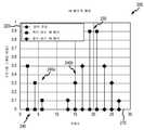
도 2는 멀티-톤 구동 신호의 상호변조 왜곡 신호들을 예시하는 그래프(200)를 도시한다.
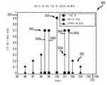
도 3은 상호변조 왜곡을 예시하는 그래프(300)를 도시한다.
도 4는 상호변조 왜곡 신호 간섭을 방지하기 위한 주파수 간격들을 예시하는 그래프(400)를 도시한다.
도 5는 상호변조 왜곡 신호 간섭을 방지하기 위한 주파수 간격들을 예시하는 그래프(500)를 도시한다.
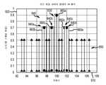
도 6은 상호변조 왜곡 신호 간섭을 방지하기 위한 주파수 간격들을 예시하는 그래프(600)를 도시한다.
도 7은 실시예에 따른, 상호변조 왜곡 신호 간섭을 방지하기 위한 주파수 간격들을 결정하는 방법(700)을 도시한다.
도 8은 센서 조립체(810) 및 계측 검증 모듈(820)로 구성된 시스템(800)을 도시한다.Like reference numbers indicate like elements in all figures. It should be understood that the drawings are not necessarily to scale.
1 shows a
2 shows a
3 shows a
4 shows a
5 shows a graph 500 illustrating frequency intervals for preventing intermodulation distortion signal interference.
6 shows a graph 600 illustrating frequency intervals for preventing intermodulation distortion signal interference.
7 illustrates a
8 shows a
도 1-8 및 하기의 설명은 당업자들에게 상호변조 왜곡 신호 간섭을 방지하기 위한 주파수 간격의 실시예들의 최상의 모드를 제조 및 사용하는 방법을 교시하기 위한 특정 예들을 묘사한다. 발명 원리들을 교시하는 목적을 위해, 일부 종래의 양상들이 간략화되거나 생략되었다. 당업자들은 본 명세서의 범위 내에 있는, 이들 예들로부터의 변형예들을 인지할 것이다. 당업자들은, 후술되는 특징들이 다양한 방식들로 조합되어 상호변조 왜곡 신호 간섭을 방지하기 위한 최적의 주파수 간격을 결정하는 다수의 진동들을 형성할 수 있다는 것을 인지할 것이다. 결과적으로, 후술되는 실시예들은, 후술되는 특정 예들에 한정되지 않고, 청구범위 및 그 등가물들에 의해서만 한정된다.1-8 and the description below depict specific examples for teaching those skilled in the art how to make and use the best mode of frequency spacing embodiments for preventing intermodulation distortion signal interference. For the purpose of teaching inventive principles, some conventional aspects have been simplified or omitted. Those skilled in the art will recognize variations from these examples that are within the scope of this disclosure. Those of skill in the art will recognize that the features described below can be combined in various ways to form a number of oscillations that determine the optimal frequency spacing for preventing intermodulation distortion signal interference. Consequently, the embodiments described below are not limited to the specific examples described below, but are limited only by the claims and their equivalents.
상호변조 왜곡 신호들에 의한 간섭은 진동계의 센서 조립체에 인가될 구동 신호와 같은 제1 신호의 주파수를 결정하고, 제1 신호의 주파수에 관한 복조 윈도우를 설정함으로써 방지될 수 있다. 제1 신호와 혼합될 때 상호변조 왜곡 신호를 생성하는 제2 신호의 주파수는, 상호변조 왜곡 신호의 주파수가 복조 윈도우 외부에 있도록 결정될 수 있다. 따라서, 상호변조 왜곡 신호는 센서 조립체의 주파수 응답의 특징에 포함되지 않는다. 결과적으로, 특징은 더 정확하고, 따라서 센서 조립체에서의 부식, 침식, 침전들 및 다른 이슈들이 신뢰할 수 있게 검출될 수 있다.Interference by intermodulation distortion signals can be prevented by determining the frequency of a first signal, such as a drive signal to be applied to the sensor assembly of the vibrating system, and setting a demodulation window for the frequency of the first signal. The frequency of the second signal that produces the intermodulation distortion signal when mixed with the first signal may be determined such that the frequency of the intermodulation distortion signal is outside the demodulation window. Accordingly, the intermodulation distortion signal is not included in the characteristics of the frequency response of the sensor assembly. As a result, the characterization is more accurate and thus corrosion, erosion, deposits and other issues in the sensor assembly can be reliably detected.
도 1은 상호변조 왜곡 신호 간섭을 방지하기 위한 주파수 간격들을 사용하는 진동계(5)를 도시한다. 도 1에 도시된 바와 같이, 진동계(5)는 센서 조립체(10) 및 계측 전자장치(20)를 포함한다. 센서 조립체(10)는 프로세스 물질의 질량 유량 및 밀도에 응답한다. 계측 전자장치(20)는 리드들(leads)(100)을 통해 센서 조립체(10)에 연결되어, 경로(26)를 통해 밀도, 질량 유량 및 온도 정보뿐만 아니라 다른 정보를 제공한다.1 shows a
센서 조립체(10)는 한 쌍의 매니폴드들(manifolds)(150 및 150'), 플랜지 넥부들(flange necks)(110 및 110')을 갖는 플랜지들(flanges)(103 및 103'), 한 쌍의 평행한 도관들(130 및 130'), 구동 메커니즘(180), 저항 온도 검출기(RTD)(190) 및 한 쌍의 픽-오프 센서들(pick-off sensors)(170l, 170r)을 포함한다. 도관들(130 및 130')은, 도관 장착 블록들(120 및 120')에서 서로를 향해 수렴하는 2개의 본질적으로 직선형인 유입구 레그들(inlet legs)(131, 131') 및 유출구 레그들(outlet legs)(134, 134')를 갖는다. 도관들(130, 130')은 자신들의 길이를 따르는 2개의 대칭 위치들에서 구부러지고, 자신들의 길이 전체에 걸쳐 본질적으로 평행하다. 브레이스 바아들(brace bars)(140 및 140')은, 각각의 도관(130, 130')이 발진하게 되는 중심인 축(W 및 W')을 규정하는 역할을 한다. 도관들(130, 130')의 레그들(131, 131' 및 134, 134')은 도관 장착 블록들(120 및 120')에 고정적으로 부착되고, 이들 블록들은 결국 매니폴드들(150 및 150')에 고정적으로 부착된다. 이것은 센서 조립체(10)를 통한 연속적인 폐쇄 물질 경로를 제공한다.The
구멍들(102 및 102')을 갖는 플랜지들(103 및 103')이, 유입구 단부(104) 및 유출구 단부(104')를 통해, 측정되고 있는 프로세스 물질을 운반하는 프로세스 라인(도시되지 않음) 내로 연결되는 경우, 물질은 플랜지(103)의 오리피스(orifice)(101)를 통해 진동계의 유입구 단부(104)로 진입하고 매니폴드(150)를 통해 표면(121)을 갖는 도관 장착 블록(120)으로 안내된다. 매니폴드(150) 내에서, 물질은 분할되어 도관들(130, 130')을 통해 라우팅된다(routed). 도관들(130, 130')을 빠져나갈 때, 프로세스 물질은 표면(121')을 갖는 도관 장착 블록(120') 및 매니폴드(150') 내에서 단일 스트림(stream)으로 재조합되고, 이후에 구멍들(102')을 갖는 플랜지(103')에 의해 프로세스 라인(도시되지 않음)에 연결된 출구 단부(104')로 라우팅된다.A process line (not shown) in which
도관들(130, 130')은, 굽힘 축들(W--W 및 W'--W') 각각에 대해 실질적으로 동일한 질량 분포, 관성 모멘트들(moments of inertia) 및 영률(Young's modulus)을 갖도록 선택되어 도관 장착 블록들(120, 120')에 적절하게 장착된다. 이들 굽힘 축들은 브레이스 바아들(140, 140')을 관통한다. 도관들의 영률이 온도에 따라 변화하고, 이러한 변화가 유량 및 밀도의 계산에 영향을 미치기 때문에, RTD(190)는 도관(130')에 장착되어 도관(130')의 온도를 연속적으로 측정한다. 도관(130’)의 온도, 및 따라서 RTD를 통과하는 주어진 전류에 대해 RTD(190)에 걸쳐 나타나는 전압은 도관(130’)을 통과하는 물질의 온도에 의해 좌우된다. RTD(190)에 나타나는 온도 의존성 전압은 주지된 방법에서 계측 전자장치(20)에 의해 사용되어, 도관 온도의 임의의 변화로 인한 도관들(130, 130')의 탄성 계수의 변화를 보상한다. RTD(190)는 리드(195)에 의해 계측 전자장치(20)에 연결된다.The
도관들(130, 130’) 둘 모두는 자신들 개개의 굽힘 축들(W 및 W')을 중심으로 반대 방향들로 그리고 유량계의 소위 말하는 제1의 역위상(out-of-phase) 굽힘 모드로 구동 메커니즘(180)에 의해 구동된다. 이러한 구동 메커니즘(180)은 도관(130’)에 장착된 자석, 및 도관(130)에 장착되고 도관들(130, 130’) 둘 모두를 진동시키기 위해 교류가 통과되는 대향 코일과 같은, 잘 알려진 많은 어레인지먼트들 중 임의의 하나를 포함할 수 있다. 적합한 구동 신호가 계측 전자장치(20)에 의해 리드(185)를 통해 구동 메커니즘(180)에 인가된다.Both
계측 전자장치(20)는 리드(195) 상의 RTD 온도 신호, 및 좌측 및 우측 센서 신호들(165l, 165r)을 운반하는 리드(100) 상에 각각 나타나는 좌측 및 우측 센서 신호들을 수신한다. 계측 전자장치(20)는 리드(185) 상에 나타나는 구동 신호를 구동 메커니즘(180)에 생성하여, 도관들(130, 130')을 진동시킨다. 계측 전자장치(20)는 좌측 및 우측 센서 신호들 및 RTD 신호를 프로세싱하여 센서 조립체(10)를 통과하는 물질의 질량 유량 및 밀도를 산출한다. 이러한 정보는, 다른 정보와 함께, 경로(26)를 통해 계측 전자장치(20)에 의해 신호로서 적용된다.
도 2는 멀티-톤 구동 신호의 상호변조 왜곡 신호들을 예시하는 그래프(200)를 도시한다. 도 2에 도시된 바와 같이, 그래프(200)는 주파수 축(210) 및 크기 축(220)을 포함한다. 주파수 축은 헤르츠(Hz) 단위이고, 0 내지 30의 범위이다. 크기 축(220)은 풀 스케일 비율이고, 0 내지 1의 범위이다. 그래프(200)는 또한, 대칭적으로 약 20Hz에 중심을 둔 2개의 신호(230)를 포함한다. 도 2에 도시된 바와 같이, 그래프(200)는, 짝수-차수 상호변조 왜곡 신호(240a) 및 홀수-차수 상호변조 왜곡 신호(240b)로 구성된 상호변조 왜곡 신호(240)를 포함한다.2 shows a
2개의 신호들(230)은 대칭적으로 약 20Hz에 중심을 두고 약 0.9의 크기를 갖는 것으로 도시된다. 2개의 신호들(230)은, 예컨대, 멀티-톤 구동 신호를 사용하여 도 1을 참조하여 위에 설명된 센서 조립체(10)에 제공될 수 있다. 더 구체적으로, 멀티-톤 구동 신호는, 구동 메커니즘(180)에 제공되는 2개의 신호들(230)로 구성될 수 있다.The two
상호변조 왜곡 신호들(240)은 리드들(100) 상의 센서 신호들 내에 있을 수 있고, 계측 전자장치(20) 또는 센서 조립체(10)에 의해 발생될 수 있다. 예컨대, 상호변조 왜곡 신호들(240)은, 다중-톤 구동 신호가 계측 전자장치(20)의 증폭기에 근접하거나 포화 상태에 있기 때문에 생성될 수 있다. 상호변조 왜곡 신호들(240)은 또한 픽오프 센서들(170l, 170r) 및 구동 메커니즘(180)과 같은 센서 조립체(10), 또는 센서 조립체(10)의 다른 디바이스들 또는 구조들의 비-선형성들로 인한 것일 수 있다. 상호변조 왜곡 신호들(240)의 주파수들은 2개의 신호들(230)의 주파수들 사이의 차이의 배수들이다. 인지될 수 있는 바와 같이, 더 많은 입력 신호들이 추가됨에 따라, 상호변조 왜곡 신호들의 수가 증가하고, 이는 하나 이상의 상호변조 왜곡 신호들로 하여금 입력 신호들의 동일한 주파수를 갖게 할 수 있다.Intermodulation distortion signals 240 may be in sensor signals on
도 3은 상호변조 왜곡을 예시하는 그래프(300)를 도시한다. 도 3에 도시된 바와 같이, 그래프(300)는 주파수 축(310) 및 크기 축(320)을 포함한다. 주파수 축(310)은 헤르츠(Hz) 단위이고, 95 내지 105Hz의 범위이다. 크기 축(320)은 풀 스케일 비율이고, 0 내지 1의 범위이다. 그래프(300)는 제1 신호(330)를 포함하며, 이는 '구동 톤'으로 라벨링되고, 멀티-톤 구동 신호의 공진 컴포넌트일 수 있다. 제1 신호(330)는 100Hz의 주파수를 갖는다.3 shows a
멀티-톤 구동 신호의 비-공진 컴포넌트들(예컨대, 센서 조립체의 공진 주파수에 없음)일 수 있는 테스트 톤들(340)이 또한 도시된다. 테스트 톤들(340)은 제2 내지 제5 신호(340d)로 구성된다. 그래프(300)는 또한 상호변조 왜곡 신호들(350)을 포함한다. 명확성 및 토론을 목적으로, 가능한 상호변조 왜곡 신호들 모두가 도시되지는 않는다. 대신에, 도 3에 도시된 상호변조 왜곡 신호들(350)은 제1 신호(330) 및 제3 신호(340b)로부터 생성된다. 상호변조 왜곡 신호들(350) 중 하나는 제4 신호(340c)와 동일한 주파수를 갖는 간섭 신호(350a)이다. 테스트 톤들(340)은 진동계(5)의 리드(185) 상에 나타나는 구동 신호와 같은 구동 신호에 주입될 수 있다. 따라서, 리드(185) 상에 나타나는 구동 신호는 제1 신호(330) 및 제2 내지 제5 신호들(340a-340d)로 구성될 수 있다.Also shown are
제2 내지 제5 신호들(340a-340d)의 크기들은 측정되어, 센서 조립체(10)를 특징화하는 데 사용될 수 있다. 예컨대, 제2 내지 제5 신호들(340a-340d) 중 하나에 대응하는 출력의 크기 비율은 해당 주파수에서 센서 조립체(10)의 응답을 특징화할 수 있다. 상이한 주파수들에서의 4개의 테스트 톤들을 활용함으로써, 주파수들의 범위에 걸친 센서 조립체(10)의 주파수 응답이 근사화될 수 있다. 그러나, 제4 신호(340c)와 동일한 주파수에 있는 간섭 신호(350a)가 테스트 톤들(340) 중 하나가 아니며 주파수 응답에 대한 입력으로서 측정되지 않기 때문에, 센서 조립체(10)의 주파수 응답이 부정확하고, 따라서 침식, 부식, 침전들 등을 정확하게 검출할 수 없다.The magnitudes of the second to
간섭 신호(350a)의 주파수는 제1 신호(330)와 제3 신호(340b) 사이의 주파수 간격을 변경함으로써 변경될 수 있다. 더 구체적으로, 간섭 신호(350a)의 주파수는 제1 신호(330)와 제3 신호(340b)의 주파수 사이의 차이의 배수일 수 있다. 따라서, 제3 신호(340b)의 주파수를 증가 또는 감소시키는 것은 간섭 신호(350a)의 주파수를 증가 또는 감소시킬 것이다. 이것은 간섭 신호(350a)를 제4 신호(340c)로부터 멀어지게 이동시킬 것이고, 이로써, 간섭 신호(350a)가 센서 조립체(10)의 주파수 응답의 특징화에 포함되는 것을 방지할 것이다.The frequency of the
그러나, 간섭 신호(350a)를 제4 신호(340c)로부터 멀리 간단히 이동시키는 것은 간섭 신호(350a)가 센서 조립체(10)의 주파수 응답의 특징화에 포함되는 것을 방지할 수는 없다. 예컨대, 간섭 신호(350a)의 주파수가 제4 신호(340c)의 주파수와 상이할지라도, 간섭 신호(350a)는 여전히 복조 윈도우 내에 있을 수 있고, 따라서 센서 조립체로부터의 응답 신호의 간섭 컴포넌트들을 유도할 수 있다.However, simply moving the interfering
도 4는 상호변조 왜곡 신호 간섭을 방지하기 위한 주파수 간격들을 예시하는 그래프(400)를 도시한다. 도 4에 도시된 바와 같이, 그래프(400)는 주파수 축(410) 및 크기 축(420)을 포함한다. 주파수 축(410)은 헤르츠(Hz) 단위이고, 92 내지 108Hz의 범위이다. 크기 축(420)은 풀 스케일 비율이고, 0 내지 1의 범위이다. 그래프(400)는, 센서 조립체의 공진 주파수에서의 구동 톤 또는 공진 신호일 수 있는 제1 신호(430)를 포함한다. 멀티-톤 구동 신호의 비-공진 컴포넌트인 테스트 톤일 수 있는 제2 신호(440), 및 상호변조 왜곡 신호(450)가 또한 도시된다. 또한 제1 신호(430)와 연관된 제1 복조 윈도우(460a) 및 제2 신호(440)와 연관된 제2 복조 윈도우(460b)가 도 4에 도시된다.4 shows a
제1 및 제2 복조 윈도우들(460a, 460b)은, 제1 및 제2 신호들(430, 440)이 통과하게 허용하는 제1 및 제2 신호들(430, 440)의 주파수들을 중심으로 한 주파수 범위들일 수 있다. 예컨대, 제1 및 제2 복조 윈도우들(460a, 460b)은 폭이 약 1Hz일 수 있다. 따라서, 제1 신호(430)에 대한 복조 윈도우는 약 99.5Hz 내지 약 100.5Hz의 범위일 수 있다. 제2 신호(440)에 대한 복조 윈도우는 약 101.5Hz 내지 약 102.5Hz의 범위일 수 있다. 상호변조 왜곡 신호들(450)은, 제1 및 제2 복조 윈도우(460a, 460b) 내에 없는, 98 및 104Hz의 주파수들에 있다. 결과적으로, 상호변조 왜곡 신호들(450)은 센서 조립체(10)의 주파수 응답을 결정하는 데 포함되지 않는다. 추가적인 테스트 톤들과 같은 추가적인 신호들은, 아래에 논의되는 바와 같이, 주파수 간격들이 적절하게 선택되면, 복조 윈도우들 내에 놓이지 않을 수 있는 추가적인 상호변조 왜곡 신호들을 발생시킬 것이다.The first and
도 5는 상호변조 왜곡 신호 간섭을 방지하기 위한 주파수 간격들을 예시하는 그래프(500)를 도시한다. 도 5에 도시된 바와 같이, 그래프(500)는 주파수 축(510) 및 크기 축(520)을 포함한다. 주파수 축(510)은 헤르츠(Hz) 단위이고, 92 내지 108Hz의 범위이다. 크기 축(520)은 풀 스케일 비율이고, 0 내지 1의 범위이다. 그래프(500)는, 센서 조립체의 공진 주파수에서의 구동 톤 또는 신호일 수 있는 제1 신호(530)를 포함한다. 또한, 제2 신호(540a), 제3 신호(540b), 제4 신호(540c) 및 제5 신호(540d)로 구성되며, 멀티-톤 구동 신호의 비-공진 사인파 컴포넌트(non-resonant sinusoidal components)들일 수 있는 테스트 톤들(540)이 도시된다. 그래프(500)는 또한 상호변조 왜곡 신호들(550)을 포함한다. 제1 신호(530) 및 테스트 톤들(540)과 연관된 복조 윈도우들(560)이 또한 도시된다. 복조 윈도우들(560)은, 제1 내지 제5 신호(530, 540a-540d)와 각각 연관된 제1 내지 제5 복조 윈도우(560a-560e)를 포함한다.5 shows a graph 500 illustrating frequency intervals for preventing intermodulation distortion signal interference. As shown in FIG. 5 , the graph 500 includes a
제1 신호(530) 및 제2 내지 제5 신호(540a-540d)는 리드(185) 상의 멀티-톤 구동 신호를 포함할 수 있다. 제1 신호(530)는, 100Hz인 것으로 도시된 센서 조립체의 공진 주파수일 수 있다. 제2, 제3, 제4 및 제5 신호들(540a-540d)은 각각 95, 97, 102 및 103.5Hz인 것으로 도시된다. 제2 내지 제5 신호들(540a-540d)은 제1 신호(530)로부터 오프셋되고, 서로 주파수 간격들을 갖는다. 주파수 간격들은, 도 5에 도시된 바와 같이, 상호변조 왜곡 신호들(550)이 제1 내지 제4 복조 윈도우들(560b-560e) 내에 있지 않다는 것을 보장하도록 선택될 수 있다. 더 구체적으로, 상호변조 왜곡 신호들(550)의 모든 주파수들은 제1 신호(530) 및 제2 내지 제5 신호들(540a-540d)의 다양한 주파수 간격들에 대해 결정될 수 있다. 인지될 수 있듯이, 다른 주파수 간격들은, 복조 윈도우(560) 내에 또한 없는 상호변조 왜곡 신호들(550)을 발생시킬 수 있다.The
또한, 센서 조립체(10)는 센서 조립체(10)가 가볍게 댐핑되는 주파수들의 범위를 가질 수 있으며, 이는 본원에서 센서 조립체(10)의 주파수 응답 대역폭으로 지칭된다. 더 구체적으로, 센서 조립체(10)는 구동 톤 주파수를 중심으로 매우 가볍게 댐핑될 수 있으며, 여기서 센서 조립체(10)의 응답은 구동 톤 주파수로부터 멀어지게 빠르게 감소된다. 주파수 간격들이 너무 크면, 제1 신호(530)는 주파수 응답 대역폭 내에 중심을 둘 수 있고, 테스트 톤들(540) 중 하나 이상은 주파수 응답 대역폭 외부에 있을 수 있다. 이는, 센서 조립체(10)의 주파수 응답을 특징화하기에 부적절한 신호 대 잡음비들을 갖는 컴포넌트들을 갖는 센서 신호를 발생시킬 수 있다.In addition, the
이러한 신호 대 잡음비 이슈를 피하기 위해, 테스트 톤들(540)의 주파수들은, 해당 주파수들이 센서 조립체(10)의 주파수 응답 대역폭 내에 놓이도록 제1 신호(530)의 주파수에 근접할 수 있다. 따라서, 도 5의 실시 예에서, 제2 신호(540a) 및 제5 신호(540d)인 테스트 톤들(540)의 최저 주파수와 최고 주파수 사이의 주파수 간격을 최소화하는 것이 바람직할 수 있다. 이 최소화의 예는 도 6을 참조하여 다음에 논의된다.To avoid this signal-to-noise ratio issue, the frequencies of the
도 6은 상호변조 왜곡 신호 간섭을 방지하기 위한 주파수 간격들을 예시하는 그래프(600)를 도시한다. 도 6에 도시된 바와 같이, 그래프(600)는 주파수 축(610) 및 크기 축(620)을 포함한다. 주파수 축(610)은 헤르츠(Hz) 단위이고, 92 내지 108Hz의 범위이다. 크기 축(620)은 풀 스케일 비율이고, 0 내지 1의 범위이다. 그래프(600)는, 센서 조립체의 공진 주파수에서의 구동 톤 또는 신호일 수 있는 제1 신호(630)를 포함한다. 또한, 제2 신호(640a), 제3 신호(640b), 제4 신호(640c) 및 제5 신호(640d)로 구성된 테스트 톤들(640)이 도시된다. 테스트 톤들(640)은 비-공진 주파수들에서의 사인파 컴포넌트들일 수 있다. 그래프(600)는 또한 상호변조 왜곡 신호들(650)을 포함한다. 제1 신호(630) 및 테스트 톤들(640)과 연관된 복조 윈도우들(660)이 또한 도시된다. 복조 윈도우들(660)은 제1 신호(630) 및 제2 신호(640a) 내지 제5 신호(640d)와 연관된 제1 내지 제5 복조 윈도우(660a-660e)를 포함한다.6 shows a graph 600 illustrating frequency intervals for preventing intermodulation distortion signal interference. As shown in FIG. 6 , the graph 600 includes a
인지될 수 있듯이, 제2 및 제5 신호(640a, 640d)는 도 5를 참조하여 위에 설명된 제2 및 제5 신호(540a, 540d)보다 서로 더 근접하다. 제2 및 제5 신호(640a, 640d)는 센서 조립체의 주파수 응답 대역폭 내에 있을 수 있다. 결과적으로, 테스트 톤들(640)에 대응하는 센서 신호 내의 신호들은 수용 가능한 신호 대 잡음비들을 가질 수 있다. 추가적으로, 상호변조 왜곡 신호들(650) 중 일부는 복조 윈도우들(660b-660e)에 인접하다. 더 구체적으로, 상호변조 왜곡 신호들(650) 중 일부는 복조 윈도우들(660b-660e)의 외부에 있지만 그 옆에 있다. 따라서, 상호변조 왜곡 신호들(650)은, 테스트 톤들(640)에 대응하는 센서 신호의 컴포넌트들이 통과하게 허용하면서, 복조 윈도우들(660b-660e)에 의해 통과되지 않는다.As can be appreciated, the second and
따라서, 상호변조 왜곡 신호들(650)이 테스트 톤들(640)에 대응하는 신호를 간섭하는 것을 방지함으로써, 센서 조립체(10)의 주파수 응답의 특징화가 더 정확해질 수 있다. 주파수 응답의 특징화는 또한 제2 및 제5 신호(640a, 640d) 사이의 더 가까운 주파수 간격으로부터 발생된 충분한 신호 대 잡음비로 인해 더 정확할 수 있다. 주파수 간격들을 결정할 수 있는 예시적인 방법들 및 시스템들은 다음에 더 상세히 설명된다.Thus, by preventing the intermodulation distortion signals 650 from interfering with the signal corresponding to the
도 7은 실시예에 따른, 상호변조 왜곡 신호 간섭을 방지하기 위한 주파수 간격들을 결정하는 방법(700)을 도시한다. 도 7에 도시된 바와 같이, 방법(700)은 단계(710)에서 진동계의 센서 조립체에 인가될 제1 신호의 주파수를 결정한다. 단계(720)에서, 방법(700)은 제1 신호의 주파수에 관한 복조 윈도우를 설정한다. 방법(700)은, 단계(730)에서, 제1 신호 및 센서 조립체에 인가될 제2 신호에 의해 생성된 상호변조 왜곡 신호의 주파수가 복조 윈도우 외부에 있도록, 제2 신호의 주파수를 결정한다.7 illustrates a
제1 신호의 주파수는, 예컨대, 리드(100) 상에 나타나는 좌측 및 우측 센서 신호들에 기반하여 신호를 생성함으로써 단계(710)에서 결정될 수 있다. 즉, 제1 신호는 센서 조립체(10)에 제공되는 멀티-톤 구동 신호의 구동 톤일 수 있고, 이어서 센서 조립체(10)는 구동 톤의 주파수를 결정하는 피드백 루프에 좌측 및 우측 센서 신호들을 제공한다.The frequency of the first signal may be determined at
단계(720)에서, 제1 신호의 주파수에 관한 복조 윈도우는, 예컨대, 제1 신호의 주파수와 연관된 상한 및 하한 값들을 결정함으로써 설정될 수 있다. 제1 신호의 주파수에 공차 값(tolerance value)을 합산함으로써 복조 윈도우의 상한 값이 설정될 수 있고, 제1 신호의 주파수로부터 공차 값을 감산함으로써 복조 윈도우의 하한 값이 설정될 수 있다. 따라서, 복조는 제1 주파수를 중심으로 대칭적이다. 대안적으로, 상한 및 하한 값들은 제1 주파수를 중심으로 대칭적이지 않을 수 있고, 따라서 상이한 양들만큼 제1 주파수로부터 오프셋될 수 있다.In
단계(730)에서, 제2 신호의 주파수는, 예컨대, 제2 주파수를 반복적으로 값으로 설정하고, 상호변조 왜곡 신호의 주파수를 결정하고, 상호변조 왜곡 신호가 복조 윈도우 내에 있는지를 결정함으로써 결정될 수 있다. 예컨대, 복조 윈도우의 상한 또는 하한의 주파수 및 제1 신호의 주파수에 기반하여 상호변조 왜곡 신호의 주파수를 결정하는 것과 같은 다른 방법들이 이용될 수 있다.In
일 예에서, 제2 신호의 주파수를 결정할 때, 이산 해법 공간(discrete solution space)이 이용될 수 있다. 제1 신호의 복조 윈도우는 모든 테스트 주파수들이 제1 신호의 주파수(예컨대, 구동 톤 주파수) 및 임의의 다른 테스트 톤 주파수로부터 적어도 복조 윈도우 폭(dF)이 되도록 강제한다. IM 왜곡 신호들이 입력 주파수들 사이의 간격들에 기반하여 나타나기 때문에, 특정 입력 쌍으로 인한 상호변조 왜곡 신호들은 또한 해당 주파수들로부터 적어도 dF를 나타낼 것이다. 따라서, 해법 공간은 제1 신호의 주파수에 중심을 둔 해상도의 그리드 상의 테스트 톤들(dF)로 제한된다. 이러한 단순화로, 무차별 최적화 절차(brute-force optimization procedure)를 따르는 것이 실현 가능하게 된다. 예컨대, 센서 조립체의 주파수 응답 대역폭일 수 있는 20 dF의 대역폭 내에 모두 배치된 4개의 테스트 톤의 전체 검색 공간은 n-choose-k 문제이다. 2 * 20 = 40개의 잠재적 주파수들로부터(구동 주파수가 사용될 수 없기 때문에), 4개의 주파수들이 선택되어야 한다. 이 선택을 수행하는 방법들의 수는
방법(700)은 제1 신호의 상이한 주파수들에 대해 반복될 수 있다. 예컨대, 제1 신호의 주파수를 결정하는 단계는 제1 신호의 다른 주파수를 결정하는 단계를 포함할 수 있다. 이는 진동계들의 클래스와 연관된 주파수들의 범위 내에 있는 주파수일 수 있다. 이 캐리어 주파수와 연관된 제2 신호의 주파수는 캐리어 주파수에서 제1 신호로 제2 신호를 변조함으로써 결정될 수 있다. 기저 대역 주파수에서 설정된 복조 윈도우는 캐리어 주파수에서의 복조 윈도우와 동일할 수 있거나 동일하지 않을 수 있다. 이 프로세스는 다음의 논의에 예시된다.
예컨대, [-6-4 5 7]의 기본 테스트 톤 주파수들에서 제2 내지 제5 신호로 구성된 기본 테스트 톤 벡터가 획득될 수 있다. 이 기본 테스트 톤 주파수들의 벡터는 다른 캐리어 주파수로 변조될 수 있으며, 이는 dF로 정의된 상이한 복조 윈도우 폭들을 가질 수 있다. 이 예에서, 방법(700)은 제1 주파수가 100Hz와 같이 70 내지 125Hz의 범위 내에 있는 것으로 결정할 수 있다. 방법(700)은, 단계(720)에서, 복조 윈도우의 폭(dF)이 0.267Hz인 것으로 결정할 수 있다. 방법(700)은 제2 신호의 주파수가 100Hz 마이너스 1.6Hz인 것으로 결정할 수 있다. 복조 윈도우 폭의 폭이 0.267Hz이기 때문에, 제2 톤의 주파수는 기본 톤 벡터의 엘리먼트와 dF를 곱함으로써 결정되는데, 이 경우에 -1.6Hz와 동일한 -6*0.267Hz이다. 추가적인 테스트 톤들과 같은 추가적인 신호들에 대해 유사한 단계들이 수행될 수 있다.For example, a basic test tone vector composed of the second to fifth signals at basic test tone frequencies of [-6-4 5 7] may be obtained. This vector of fundamental test tone frequencies may be modulated with a different carrier frequency, which may have different demodulation window widths defined as dF. In this example, the
예컨대, 389.1Hz의 제1 신호 주파수 또는 캐리어 주파수는 351Hz 내지 600Hz의 주파수 범위 내에 있을 수 있고, 이는 계측 조립체로부터의 센서 신호로부터 결정될 수 있다. 351Hz 내지 600Hz의 주파수 범위는 폭이 1.3333Hz의 폭을 갖는 복조 윈도우를 가질 수 있다. 따라서, 기본 테스트 톤 벡터는 [-8.000 -5.333 6.667 9.333] Hz의 테스트 톤 벡터에 도달하기 위해 1.3333 Hz와 곱셈될 수 있다. 제1 신호에 대한 389.1Hz의 캐리어 주파수에 대해, 제2 신호는 389.1Hz - 8.0Hz와 동일한 381.1Hz의 주파수를 가질 것이다.For example, the first signal frequency or carrier frequency of 389.1 Hz may be within a frequency range of 351 Hz to 600 Hz, which may be determined from a sensor signal from the metrology assembly. A frequency range of 351 Hz to 600 Hz may have a demodulation window having a width of 1.3333 Hz. Thus, the base test tone vector can be multiplied by 1.3333 Hz to arrive at a test tone vector of [-8.000 -5.333 6.667 9.333] Hz. For a carrier frequency of 389.1 Hz for the first signal, the second signal will have a frequency of 381.1 Hz equal to 389.1 Hz - 8.0 Hz.
위에서 논의된 바와 같이, 방법(700)은 단계(730)에서 상호변조 왜곡 신호들이 제1 신호의 복조 윈도우 외부에 있음을 검증할 수 있다. 이 단계는, 기본 톤 벡터가 원하는 캐리어 주파수들 모두에 대해 작동한다고 보장하기 위해 상이한 캐리어 주파수들에 대해 수행될 수 있다. 예컨대, 위에 논의된 바와 같이, 기본 테스트 톤 벡터는 제2 내지 제5 신호들 및 70 내지 125Hz 범위의 이들의 연관된 주파수들에 대해 결정되고, 이어서, 위에 설명된 바와 같이, 상이한 캐리어 주파수들로 변조된 제2 내지 제5 신호들의 기본 테스트 톤 벡터를 사용함으로써 다른 캐리어 주파수들에서 검증될 수 있다.As discussed above, the
결과적인 표가 다음과 같을 수 있다.The resulting table may be as follows.

따라서, 위에 논의된 캐리어 또는 구동 톤, 389.10Hz의 주파수의 예에 대해, 제2 신호는 381.10Hz에 있을 수 있고, 제3 신호는 383.77Hz에 있을 수 있고, 제4 신호는 395.77Hz에 있을 수 있고, 제5 신호는 398.43Hz에 있을 수 있다.Thus, for the example of the carrier or drive tone discussed above, a frequency of 389.10 Hz, the second signal could be at 381.10 Hz, the third signal could be at 383.77 Hz, and the fourth signal could be at 395.77 Hz. and the fifth signal may be at 398.43 Hz.
방법(700)은 추가적으로, 제1 신호의 주파수를 포함하는 대역폭을 결정하는 단계, 및 제2 신호의 주파수가 제1 신호의 주파수를 포함하는 대역폭 내에 있도록 제2 신호의 주파수를 결정하는 단계를 포함할 수 있다. 대역폭은, 제1 및 제2 신호가 인가되는 센서 조립체의 주파수 응답 대역폭일 수 있다. 예컨대, 위에 설명된 센서 조립체(10)는, 응답이 실질적으로 공진이거나 약하게 댐핑되는 비교적 좁은 범위의 주파수들을 가질 수 있다. 제2, 제3 또는 제4 신호들은 계측 검증을 적절하게 수행하기 위해 이 대역폭 내에 있을 필요가 있을 수 있다.
도 8은 센서 조립체(810) 및 계측 검증 모듈(820)로 구성된 시스템(800)을 도시한다. 도 8에 도시된 바와 같이, 센서 조립체(810)는 계측 검증 모듈(820)에 통신 가능하게 커플링된다. 계측 검증 모듈(820)은 센서 조립체(810)에 구동 신호를 제공하는 구동 회로(822)를 포함한다. 센서 조립체(810)는 계측 검증 모듈(820)에 통신 가능하게 커플링되어, 센서 신호들을 계측 검증 모듈(820)에 제공한다. 복조 필터(824)는 센서 조립체(810)로부터 센서 신호들을 수신하고, 복조 필터(824)의 복조 윈도우 또는 윈도우들 내에 있는 신호들을 통과시킨다. 복조 필터(824)에 의해 통과된 신호들은 FRF 추정 유닛(825)에 제공된다. 노치 필터(826)는 또한 공진 컴포넌트를 구동 회로(822) 및 유동 및 밀도 측정 모듈(827) ― 유체의 유체 특성을 결정할 수 있음 ― 에 전달하는 센서 신호를 수신한다.8 shows a
센서 조립체(810)는 도 1을 참조하여 앞서 설명된 센서 조립체(10)를 나타내는 모델일 수 있다. 대안적으로, 센서 조립체(810)는 구동 회로(822)로부터 전기 구동 신호를 수신하는 실제 센서 조립체일 수 있다. 어느 경우에서든, 센서 조립체(810)는 계측 검증 모듈(820)로부터 멀티-톤 구동 신호를 수신하고, 센서 조립체(810)를 특징화하기 위해 센서 신호를 계측 검증 모듈(820)에 제공한다. 따라서, 멀티-톤 구동 신호는 센서 조립체(810)의 주파수 응답에 대한 입력이고, 센서 신호는 센서 조립체(810)의 주파수 응답의 출력이다. 입력과 출력을 비교함으로써, 센서 조립체(810)의 주파수 응답이 특징화될 수 있다. 추가로, 분석 해법은, 예컨대, 센서 조립체(810)의 특징에 곡선을 맞춤으로써 공식화될 수 있다.The
구동 회로(822)는, 공진 컴포넌트의 주파수를 추적하고 센서 조립체(810)에 제공된 구동 신호의 구동 톤의 주파수를 조정하는 피드백 회로로 구성될 수 있다. 구동 회로(822)는 또한, 구동 톤 및 테스트 톤들을 포함하는 멀티-톤 구동 신호일 수 있는 구동 신호를 생성 또는 제공하는 신호 생성기, 증폭기 등을 포함할 수 있다. 위에 논의된 바와 같이, 멀티-톤 구동 신호의 크레스트(crest)가 구동 증폭기의 전력 용량을 초과하면, 상호변조 왜곡 신호들이 생성될 수 있다.The
복조 필터(824)는 복조 윈도우들 내에 있는 신호들을 통과시킨다. 예컨대, 도 6을 참조하면, 복조 필터(824)는 복조 윈도우들(660b-660e) 내에 있는 신호들을 통과시킨다. 여전히 도 6을 참조하면, 상호변조 왜곡 신호들(650)은 복조 윈도우들(660b-660e) 내에 있지 않고, 따라서 복조 필터(824)에 의해 통과되지 않는다. 결과적으로, 계측 검증 모듈(820)은 제2 내지 제5 신호들(640a-640d)로 센서 조립체(810)를 정확하게 검증할 수 있다.A
계측 검증 동안 테스트 톤들(640)이 이용될 때만 상호변조 왜곡 신호들(650)이 존재할 수 있기 때문에, 복조 필터(824) 및 노치 필터(826)는 진동계(5)의 생산 동작 동안에 이용되지 않을 수 있다. 더 구체적으로, 동작 동안, 진동계(5)는 센서 조립체(810)의 공진 주파수에서의 주파수를 갖는 사인파 신호로 구성된 단일 컴포넌트 신호만을 제공할 수 있다.Since intermodulation distortion signals 650 may only be present when test tones 640 are used during metrology verification,
방법(700)으로 결정된 복조 필터(824)를 활용하는 계측 검증 동안, 도 6에 도시된 테스트 톤들(640)은 구동 회로(822)에 의해 구동 신호에 주입될 수 있다. 즉, 계측 검증 모듈(820)은 도 1에 도시된 센서 조립체(10)를 검증하기 위해 계측 전자장치(20)에서 사용될 수 있다. 따라서, 계측 검증 동안, 계측 검증 모듈(820)은 멀티-톤 구동 신호를 센서 조립체(10)에 제공한다. 추가적으로, 계측 검증 모듈(820)은 센서 조립체(10)에 의해 제공되는 센서 신호들을 복조 필터(824) 및 노치 필터(826)로 필터링할 수 있다.During metrology verification utilizing the
새롭고 유용한 진동계(5), 방법(700) 및 시스템(800)뿐만 아니라 다른 실시예들은 계측 검증 동안 상호변조 왜곡 신호 간섭을 방지할 수 있다. 더 구체적으로, 복조 필터(824)에 의해 통과된 테스트 톤들(640)을 상호변조 왜곡 신호들(650)이 손상되거나 영향을 미치지 않는 것을 보장하기 위해, 진동계(5), 방법(700) 및 시스템(800)이 사용될 수 있다. 따라서, 진동계(5)의 계측 검증은, 예컨대, 센서 조립체(810)에 인가될 제1 신호(630)의 주파수를 결정하고, 제1 신호(630)의 주파수에 관한 복조 윈도우(660a)를 설정하고, 그리고 센서 조립체(810)에 인가될 제1 신호(630) 및 제2 신호(640a)에 의해 생성된 상호변조 왜곡 신호(650)의 주파수가 복조 윈도우들(660b-660e) 외부에 있도록, 제2 신호(640a)의 주파수를 결정함으로써 명확하게 개선된다.New and
결과적으로, 계측 검증은 침식, 부식 또는 다른 조건들이 센서 조립체(10)에 존재하는지를 정확하게 결정할 수 있다. 예컨대, 멀티-톤 구동 신호의 테스트 톤(640)의 주파수는 온도 변동들로 인해 복조 윈도우(660a) 내에서 변할 수 있으며, 이는 상호변조 왜곡 신호들(650)의 주파수들을 변경한다. 테스트 톤(640)이 온도로 인해 변동할 때, 상호변조 왜곡 신호들이 복조 윈도우들(660b-660e)에 결코 존재하지 않도록 복조 윈도우들(660b-660d) 및 테스트 톤들(640)의 주파수들을 설정함으로써, 센서 조립체(10)의 주파수 응답은 정확하게 특징화될 수 있다.As a result, metrology verification can accurately determine whether erosion, corrosion or other conditions are present in the
상기 실시예들의 상세한 설명들은 본 명세서의 범위 내에 있는 것으로 본 발명자들에 의해 고려되는 모든 실시예들에 대한 철저한 설명들은 아니다. 실제로, 당업자들은 전술한 실시예들의 특정 엘리먼트들이 다른 실시예들을 생성하기 위해 다양하게 조합되거나 제거될 수 있으며, 그러한 다른 실시예들이 본 명세서의 범위 및 교시들 내에 있다는 것을 인식할 것이다. 또한, 당업자들에게는, 전술한 실시예들이 전체적으로 또는 부분적으로 조합되어 본 명세서의 범위 및 교시들 내에서 추가적인 실시예들을 생성할 수 있다는 것이 자명할 것이다.The detailed descriptions of the above embodiments are not exhaustive descriptions of all embodiments contemplated by the inventors as being within the scope of this specification. Indeed, those skilled in the art will recognize that certain elements of the above-described embodiments may be variously combined or removed to create other embodiments, and such other embodiments are within the scope and teachings of this disclosure. It will also be apparent to those skilled in the art that the above-described embodiments may be combined in whole or in part to create additional embodiments within the scope and teachings of this disclosure.
따라서, 특정 실시예들이 예시의 목적들을 위해 본원에 설명되었지만, 당업자들이 인식하는 바와 같이, 본 명세서의 범위 내에서 다양한 등가 변형예들이 가능하다. 본원에 제공된 교시들은 상호변조 왜곡 신호 간섭을 방지하기 위한 다른 주파수 간격들에 적용될 수 있으며, 상기에서 설명되고 첨부 도면들에 도시된 실시예들에만 적용될 수 있는 것은 아니다. 따라서, 전술한 실시예들의 범위는 하기의 청구범위로부터 결정되어야 한다.Accordingly, although specific embodiments have been described herein for purposes of illustration, various equivalent modifications are possible within the scope of this disclosure, as those skilled in the art will recognize. The teachings provided herein may be applied to other frequency intervals for preventing intermodulation distortion signal interference, and may not be applicable only to the embodiments described above and shown in the accompanying drawings. Accordingly, the scope of the above-described embodiments should be determined from the following claims.
Claims (22)
Translated fromKorean상기 센서 조립체(810)에 통신 가능하게 커플링된 계측 검증 모듈(meter verification module)(820)을 포함하고,
상기 계측 검증 모듈(820)은:
진동계(vibratory meter)의 상기 센서 조립체(810)에 인가될 제1 신호의 주파수를 결정하고;
상기 제1 신호의 주파수에 관한 복조 윈도우(demodulation window)를 설정하고; 그리고
상기 제1 신호 및 상기 센서 조립체에 인가될 제2 신호에 의해 생성된 상호변조 왜곡 신호(intermodulation distortion signal)의 주파수가 상기 복조 윈도우 외부에 있도록, 상기 제2 신호의 주파수를 결정하도록 구성되는,
상호변조 왜곡 신호 간섭을 방지하기 위한 주파수 간격들을 결정하기 위한 시스템(800).sensor assembly 810; and
a meter verification module (820) communicatively coupled to the sensor assembly (810);
The metrology verification module 820 includes:
determine a frequency of a first signal to be applied to the sensor assembly (810) of a vibratory meter;
set a demodulation window with respect to the frequency of the first signal; and
and determine the frequency of the second signal such that a frequency of an intermodulation distortion signal generated by the first signal and the second signal to be applied to the sensor assembly is outside the demodulation window;
A system (800) for determining frequency intervals for preventing intermodulation distortion signal interference.
상기 계측 검증 모듈(820)은:
상기 제1 신호의 주파수를 포함하는 대역폭을 결정하고; 그리고
상기 제2 신호의 주파수가 상기 제1 신호의 주파수를 포함하는 상기 대역폭 내에 있도록 상기 제2 신호의 주파수를 결정하도록 추가로 구성되는,
상호변조 왜곡 신호 간섭을 방지하기 위한 주파수 간격들을 결정하기 위한 시스템(800).According to claim 1,
The metrology verification module 820 includes:
determine a bandwidth comprising a frequency of the first signal; and
further configured to determine the frequency of the second signal such that the frequency of the second signal is within the bandwidth comprising the frequency of the first signal;
A system (800) for determining frequency intervals for preventing intermodulation distortion signal interference.
상기 대역폭은 상기 센서 조립체의 주파수 응답 대역폭인,
상호변조 왜곡 신호 간섭을 방지하기 위한 주파수 간격들을 결정하기 위한 시스템(800).3. The method of claim 2,
wherein the bandwidth is a frequency response bandwidth of the sensor assembly;
A system (800) for determining frequency intervals for preventing intermodulation distortion signal interference.
상기 제1 신호의 주파수는 상기 센서 조립체의 공진 주파수(resonant frequency)인,
상호변조 왜곡 신호 간섭을 방지하기 위한 주파수 간격들을 결정하기 위한 시스템(800).4. The method according to any one of claims 1 to 3,
The frequency of the first signal is a resonant frequency of the sensor assembly,
A system (800) for determining frequency intervals for preventing intermodulation distortion signal interference.
상기 상호변조 왜곡 신호는 상기 계측 검증 모듈(820) 및 상기 센서 조립체(810) 중 하나에서 생성되는,
상호변조 왜곡 신호 간섭을 방지하기 위한 주파수 간격들을 결정하기 위한 시스템(800).4. The method according to any one of claims 1 to 3,
wherein the intermodulation distortion signal is generated in one of the metrology verification module (820) and the sensor assembly (810).
A system (800) for determining frequency intervals for preventing intermodulation distortion signal interference.
상기 제1 신호 및 상기 제2 신호는, 상기 계측 검증 모듈(820)에 의해 상기 센서 조립체(810)에 인가된 구동 신호의 컴포넌트들인,
상호변조 왜곡 신호 간섭을 방지하기 위한 주파수 간격들을 결정하기 위한 시스템(800).4. The method according to any one of claims 1 to 3,
wherein the first signal and the second signal are components of a drive signal applied to the sensor assembly (810) by the metrology verification module (820).
A system (800) for determining frequency intervals for preventing intermodulation distortion signal interference.
상기 제2 신호는 상기 센서 조립체(810)의 주파수 응답을 특징화하기 위해 상기 센서 조립체(810)에 인가되는,
상호변조 왜곡 신호 간섭을 방지하기 위한 주파수 간격들을 결정하기 위한 시스템(800).4. The method according to any one of claims 1 to 3,
the second signal is applied to the sensor assembly (810) to characterize a frequency response of the sensor assembly (810);
A system (800) for determining frequency intervals for preventing intermodulation distortion signal interference.
상기 제1 신호 및 상기 센서 조립체(810)에 인가될 상기 제2 신호에 의해 생성된 상호변조 왜곡 신호의 주파수가 상기 복조 윈도우 외부에 있도록 상기 제2 신호의 주파수를 결정하도록 구성된 상기 계측 검증 모듈(820)은, 상호변조 왜곡이 상기 복조 윈도우에 근접하도록 상기 제2 신호의 주파수를 결정하도록 구성된 상기 계측 검증 모듈(820)을 포함하는,
상호변조 왜곡 신호 간섭을 방지하기 위한 주파수 간격들을 결정하기 위한 시스템(800).4. The method according to any one of claims 1 to 3,
the metrology verification module configured to determine a frequency of the second signal such that a frequency of an intermodulation distortion signal generated by the first signal and the second signal to be applied to the sensor assembly (810) is outside the demodulation window; 820 includes the metrology verification module 820 configured to determine a frequency of the second signal such that intermodulation distortion approximates the demodulation window.
A system (800) for determining frequency intervals for preventing intermodulation distortion signal interference.
상기 계측 검증 모듈(820)은, 하나 이상의 추가적인 신호들에 의해 생성된 복수의 상호변조 왜곡 신호들의 주파수들이 상기 제1 신호의 복조 윈도우 외부에 놓이도록 상기 하나 이상의 추가적인 신호들의 주파수를 결정하도록 추가로 구성되는,
상호변조 왜곡 신호 간섭을 방지하기 위한 주파수 간격들을 결정하기 위한 시스템(800).4. The method according to any one of claims 1 to 3,
The metrology verification module 820 is further configured to determine a frequency of the one or more additional signals such that frequencies of a plurality of intermodulation distortion signals generated by the one or more additional signals lie outside a demodulation window of the first signal. composed,
A system (800) for determining frequency intervals for preventing intermodulation distortion signal interference.
상기 계측 검증 모듈(820)은:
상기 제1 신호의 주파수를 포함하는 대역폭을 결정하고; 그리고
상기 하나 이상의 추가적인 신호들의 주파수들이 상기 제1 신호의 주파수를 포함하는 상기 대역폭 내에 있도록 상기 하나 이상의 추가적인 신호들의 주파수들을 결정하도록 추가로 구성되는,
상호변조 왜곡 신호 간섭을 방지하기 위한 주파수 간격들을 결정하기 위한 시스템(800).10. The method of claim 9,
The metrology verification module 820 includes:
determine a bandwidth comprising a frequency of the first signal; and
further configured to determine the frequencies of the one or more additional signals such that the frequencies of the one or more additional signals are within the bandwidth comprising the frequency of the first signal;
A system (800) for determining frequency intervals for preventing intermodulation distortion signal interference.
상기 계측 검증 모듈(820)은, 상기 하나 이상의 추가적인 신호들에 관한 복조 윈도우들을 설정하고, 그리고 상기 하나 이상의 추가적인 신호들에 의해 생성된 복수의 상호변조 왜곡 신호들의 주파수들이 상기 하나 이상의 추가적인 신호들의 복조 윈도우들 외부에 놓이도록 상기 하나 이상의 추가적인 신호들의 주파수들을 결정하도록 추가로 구성되는,
상호변조 왜곡 신호 간섭을 방지하기 위한 주파수 간격들을 결정하기 위한 시스템(800).10. The method of claim 9,
The metrology verification module 820 is configured to set demodulation windows for the one or more additional signals, and wherein frequencies of a plurality of intermodulation distortion signals generated by the one or more additional signals are configured to demodulate the one or more additional signals. further configured to determine frequencies of the one or more additional signals to lie outside windows;
A system (800) for determining frequency intervals for preventing intermodulation distortion signal interference.
상기 제1 신호의 주파수에 관한 복조 윈도우를 설정하는 단계; 및
상기 제1 신호 및 상기 센서 조립체에 인가될 제2 신호에 의해 생성된 상호변조 왜곡 신호의 주파수가 상기 복조 윈도우 외부에 있도록, 상기 제2 신호의 주파수를 결정하는 단계를 포함하는,
상호변조 왜곡 신호 간섭을 방지하기 위한 주파수 간격들을 결정하는 방법.determining a frequency of a first signal to be applied to a sensor assembly of a vibrometer;
setting a demodulation window with respect to the frequency of the first signal; and
determining the frequency of the second signal such that the frequency of the intermodulation distortion signal generated by the first signal and the second signal to be applied to the sensor assembly is outside the demodulation window;
A method of determining frequency intervals to prevent intermodulation distortion signal interference.
상기 제1 신호의 주파수를 포함하는 대역폭을 결정하는 단계; 및
상기 제2 신호의 주파수가 상기 제1 신호의 주파수를 포함하는 상기 대역폭 내에 있도록 상기 제2 신호의 주파수를 결정하는 단계를 더 포함하는,
상호변조 왜곡 신호 간섭을 방지하기 위한 주파수 간격들을 결정하는 방법.13. The method of claim 12,
determining a bandwidth comprising a frequency of the first signal; and
determining the frequency of the second signal such that the frequency of the second signal is within the bandwidth that includes the frequency of the first signal;
A method of determining frequency intervals to prevent intermodulation distortion signal interference.
상기 대역폭은 상기 센서 조립체의 주파수 응답 대역폭인,
상호변조 왜곡 신호 간섭을 방지하기 위한 주파수 간격들을 결정하는 방법.14. The method of claim 13,
wherein the bandwidth is a frequency response bandwidth of the sensor assembly;
A method of determining frequency intervals to prevent intermodulation distortion signal interference.
상기 제1 신호의 주파수는 상기 센서 조립체의 공진 주파수인,
상호변조 왜곡 신호 간섭을 방지하기 위한 주파수 간격들을 결정하는 방법.15. The method according to any one of claims 12 to 14,
the frequency of the first signal is a resonant frequency of the sensor assembly;
A method of determining frequency intervals to prevent intermodulation distortion signal interference.
상기 상호변조 왜곡 신호는 계측 전자장치 및 상기 센서 조립체 중 하나에서 생성되는,
상호변조 왜곡 신호 간섭을 방지하기 위한 주파수 간격들을 결정하는 방법.15. The method according to any one of claims 12 to 14,
wherein the intermodulation distortion signal is generated in one of metrology electronics and the sensor assembly;
A method of determining frequency intervals to prevent intermodulation distortion signal interference.
상기 제1 신호 및 상기 제2 신호는, 계측 전자장치에 의해 상기 센서 조립체에 인가된 구동 신호의 컴포넌트들인,
상호변조 왜곡 신호 간섭을 방지하기 위한 주파수 간격들을 결정하는 방법.15. The method according to any one of claims 12 to 14,
wherein the first signal and the second signal are components of a drive signal applied to the sensor assembly by metrology electronics;
A method of determining frequency intervals to prevent intermodulation distortion signal interference.
상기 제2 신호는 상기 센서 조립체를 특징화하기 위해 상기 센서 조립체에 인가되는,
상호변조 왜곡 신호 간섭을 방지하기 위한 주파수 간격들을 결정하는 방법.15. The method according to any one of claims 12 to 14,
wherein the second signal is applied to the sensor assembly to characterize the sensor assembly;
A method of determining frequency intervals to prevent intermodulation distortion signal interference.
상기 제1 신호 및 상기 센서 조립체에 인가될 상기 제2 신호에 의해 생성된 상호변조 왜곡 신호의 주파수가 상기 복조 윈도우 외부에 있도록 상기 제2 신호의 주파수를 결정하는 단계는, 상호변조 왜곡이 상기 복조 윈도우에 근접하도록 상기 제2 신호의 주파수를 결정하는 단계를 포함하는,
상호변조 왜곡 신호 간섭을 방지하기 위한 주파수 간격들을 결정하는 방법.15. The method according to any one of claims 12 to 14,
Determining a frequency of the second signal such that a frequency of an intermodulation distortion signal generated by the first signal and the second signal to be applied to the sensor assembly is outside the demodulation window, wherein the intermodulation distortion is determined by the demodulation. determining a frequency of the second signal to approximate a window;
A method of determining frequency intervals to prevent intermodulation distortion signal interference.
하나 이상의 추가적인 신호들에 의해 생성된 복수의 상호변조 왜곡 신호들의 주파수들이 상기 제1 신호의 복조 윈도우 외부에 놓이도록 상기 하나 이상의 추가적인 신호들의 주파수들을 결정하는 단계를 더 포함하는,
상호변조 왜곡 신호 간섭을 방지하기 위한 주파수 간격들을 결정하는 방법.15. The method according to any one of claims 12 to 14,
determining frequencies of the one or more additional signals such that frequencies of a plurality of intermodulation distortion signals generated by the one or more additional signals lie outside a demodulation window of the first signal;
A method of determining frequency intervals to prevent intermodulation distortion signal interference.
상기 제1 신호의 주파수를 포함하는 대역폭을 결정하는 단계; 및
상기 하나 이상의 추가적인 신호들의 주파수들이 상기 제1 신호의 주파수를 포함하는 상기 대역폭 내에 있도록 상기 하나 이상의 추가적인 신호들의 주파수들을 결정하는 단계를 더 포함하는,
상호변조 왜곡 신호 간섭을 방지하기 위한 주파수 간격들을 결정하는 방법.21. The method of claim 20,
determining a bandwidth comprising a frequency of the first signal; and
determining frequencies of the one or more additional signals such that the frequencies of the one or more additional signals are within the bandwidth that includes the frequency of the first signal;
A method of determining frequency intervals to prevent intermodulation distortion signal interference.
상기 하나 이상의 추가적인 신호들에 관한 복조 윈도우들을 설정하는 단계, 및 상기 하나 이상의 추가적인 신호들에 의해 생성된 복수의 상호변조 왜곡 신호들의 주파수들이 상기 하나 이상의 추가적인 신호들의 복조 윈도우들 외부에 놓이도록 상기 하나 이상의 추가적인 신호들의 주파수들을 결정하는 단계를 더 포함하는,
상호변조 왜곡 신호 간섭을 방지하기 위한 주파수 간격들을 결정하는 방법.21. The method of claim 20,
setting demodulation windows for the one or more additional signals, and the one or more additional signals such that frequencies of a plurality of intermodulation distortion signals generated by the one or more additional signals lie outside demodulation windows of the one or more additional signals. further comprising determining frequencies of one or more additional signals,
A method of determining frequency intervals to prevent intermodulation distortion signal interference.
Applications Claiming Priority (1)
| Application Number | Priority Date | Filing Date | Title |
|---|---|---|---|
| PCT/US2017/037530WO2018231229A1 (en) | 2017-06-14 | 2017-06-14 | Frequency spacings to prevent intermodulation distortion signal interference |
Publications (2)
| Publication Number | Publication Date |
|---|---|
| KR20200014412A KR20200014412A (en) | 2020-02-10 |
| KR102352194B1true KR102352194B1 (en) | 2022-01-21 |
Family
ID=59216056
Family Applications (1)
| Application Number | Title | Priority Date | Filing Date |
|---|---|---|---|
| KR1020207000205AActiveKR102352194B1 (en) | 2017-06-14 | 2017-06-14 | Frequency spacing to prevent intermodulation distortion signal interference |
Country Status (11)
| Country | Link |
|---|---|
| US (1) | US11169013B2 (en) |
| EP (1) | EP3638991B1 (en) |
| JP (1) | JP6827569B2 (en) |
| KR (1) | KR102352194B1 (en) |
| CN (1) | CN110730901B (en) |
| AU (1) | AU2017418300B2 (en) |
| BR (1) | BR112019024876B1 (en) |
| CA (1) | CA3067334C (en) |
| MX (1) | MX2019013471A (en) |
| RU (1) | RU2742973C1 (en) |
| WO (1) | WO2018231229A1 (en) |
Families Citing this family (4)
| Publication number | Priority date | Publication date | Assignee | Title |
|---|---|---|---|---|
| WO2018231227A1 (en)* | 2017-06-14 | 2018-12-20 | Micro Motion, Inc. | A notch filter in a vibratory flow meter |
| US11353510B1 (en)* | 2020-12-28 | 2022-06-07 | Endress+Hauser Flowtec Ag | Method for testing a device under test |
| EP4478009A3 (en)* | 2021-10-13 | 2025-02-26 | Endress+Hauser Flowtec AG | Test module, test system and test module. test arrangement for a base module and/or a measurement system electronics of a modular vibronic measurement system |
| DE102023112374A1 (en)* | 2023-05-10 | 2024-11-14 | Endress+Hauser Flowtec Ag | measuring system |
Citations (1)
| Publication number | Priority date | Publication date | Assignee | Title |
|---|---|---|---|---|
| WO2017019012A1 (en)* | 2015-07-27 | 2017-02-02 | Micro Motion, Inc. | Vibratory flowmeter test tones without ramp time |
Family Cites Families (20)
| Publication number | Priority date | Publication date | Assignee | Title |
|---|---|---|---|---|
| US5555190A (en)* | 1995-07-12 | 1996-09-10 | Micro Motion, Inc. | Method and apparatus for adaptive line enhancement in Coriolis mass flow meter measurement |
| US5907104A (en)* | 1995-12-08 | 1999-05-25 | Direct Measurement Corporation | Signal processing and field proving methods and circuits for a coriolis mass flow meter |
| US5734112A (en)* | 1996-08-14 | 1998-03-31 | Micro Motion, Inc. | Method and apparatus for measuring pressure in a coriolis mass flowmeter |
| US6009129A (en)* | 1997-02-28 | 1999-12-28 | Nokia Mobile Phones | Device and method for detection and reduction of intermodulation distortion |
| US5979246A (en)* | 1998-02-09 | 1999-11-09 | Micro Motion, Inc. | Spring rate balancing of the flow tube and a balance bar in a straight tube Coriolis flowmeter |
| US7010459B2 (en)* | 1999-06-25 | 2006-03-07 | Rosemount Inc. | Process device diagnostics using process variable sensor signal |
| US6363794B1 (en)* | 1999-08-13 | 2002-04-02 | Micro Motion, Inc. | Method and apparatus for Coriolis flowmeter having an accuracy enhancing balance bar |
| RU2420715C2 (en)* | 2001-02-09 | 2011-06-10 | Инвенсис Системс, Инк. | Multi-phase coriolis flowmetre |
| DE10131858A1 (en)* | 2001-06-30 | 2003-01-23 | Flowtec Ag | Coriolis flow rate sensor interpolates Fourier components |
| WO2007040468A1 (en)* | 2005-09-19 | 2007-04-12 | Micro Motion, Inc. | Meter electronics and methods for verification diagnostics for a flow meter |
| US9729987B2 (en)* | 2005-09-27 | 2017-08-08 | Ronald Quan | Method and apparatus to evaluate audio equipment via at least one filter for dynamic distortions and or differential phase and or frequency modulation effects |
| US9386385B2 (en)* | 2005-09-27 | 2016-07-05 | Ronald Quan | Method and apparatus to evaluate audio equipment via filter banks for dynamic distortions and or differential phase and frequency modulation effects |
| WO2013043147A1 (en)* | 2011-09-19 | 2013-03-28 | Micro Motion, Inc. | Vibratory flowmeter and method for average flow rate |
| US9658097B2 (en)* | 2012-05-11 | 2017-05-23 | Bristol, Inc. | Systems and methods to initiate a verification test within a flow meter via a flow computer |
| US8917792B2 (en)* | 2012-12-12 | 2014-12-23 | Motorola Mobility Llc | Method and apparatus for the cancellation of intermodulation and harmonic distortion in a baseband receiver |
| US9319916B2 (en)* | 2013-03-15 | 2016-04-19 | Isco International, Llc | Method and appartus for signal interference processing |
| WO2017069749A1 (en)* | 2015-10-21 | 2017-04-27 | Micro Motion, Inc. | In situ transducer calibration |
| DE102017112271A1 (en)* | 2017-06-02 | 2018-12-06 | Endress+Hauser Flowtec Ag | Sensor for measuring the mass flow of a fluid medium |
| WO2018231227A1 (en)* | 2017-06-14 | 2018-12-20 | Micro Motion, Inc. | A notch filter in a vibratory flow meter |
| CN110709678B (en)* | 2017-06-14 | 2021-09-07 | 高准公司 | Minimize peaks in multi-tone drive signals in vibration meters |
- 2017
- 2017-06-14JPJP2019569375Apatent/JP6827569B2/enactiveActive
- 2017-06-14CACA3067334Apatent/CA3067334C/enactiveActive
- 2017-06-14WOPCT/US2017/037530patent/WO2018231229A1/ennot_activeCeased
- 2017-06-14CNCN201780092015.7Apatent/CN110730901B/enactiveActive
- 2017-06-14MXMX2019013471Apatent/MX2019013471A/enunknown
- 2017-06-14AUAU2017418300Apatent/AU2017418300B2/enactiveActive
- 2017-06-14BRBR112019024876-5Apatent/BR112019024876B1/enactiveIP Right Grant
- 2017-06-14RURU2019144027Apatent/RU2742973C1/enactive
- 2017-06-14USUS16/616,199patent/US11169013B2/enactiveActive
- 2017-06-14EPEP17733284.8Apatent/EP3638991B1/enactiveActive
- 2017-06-14KRKR1020207000205Apatent/KR102352194B1/enactiveActive
Patent Citations (1)
| Publication number | Priority date | Publication date | Assignee | Title |
|---|---|---|---|---|
| WO2017019012A1 (en)* | 2015-07-27 | 2017-02-02 | Micro Motion, Inc. | Vibratory flowmeter test tones without ramp time |
Also Published As
| Publication number | Publication date |
|---|---|
| AU2017418300A1 (en) | 2019-12-19 |
| JP6827569B2 (en) | 2021-02-10 |
| KR20200014412A (en) | 2020-02-10 |
| WO2018231229A1 (en) | 2018-12-20 |
| JP2020523598A (en) | 2020-08-06 |
| MX2019013471A (en) | 2020-02-12 |
| EP3638991B1 (en) | 2021-08-04 |
| CN110730901B (en) | 2021-06-29 |
| EP3638991A1 (en) | 2020-04-22 |
| CA3067334C (en) | 2022-03-22 |
| US20200109980A1 (en) | 2020-04-09 |
| BR112019024876B1 (en) | 2023-02-07 |
| BR112019024876A2 (en) | 2020-06-09 |
| US11169013B2 (en) | 2021-11-09 |
| RU2742973C1 (en) | 2021-02-12 |
| CN110730901A (en) | 2020-01-24 |
| AU2017418300B2 (en) | 2020-10-22 |
| CA3067334A1 (en) | 2018-12-20 |
Similar Documents
| Publication | Publication Date | Title |
|---|---|---|
| KR100976233B1 (en) | Diagnostic Device and Method for Coriolis Flowmeters | |
| JP4588293B2 (en) | Apparatus and method for compensating mass flow rate of a material when an unacceptable error in flow rate occurs due to the density of the material | |
| KR102352194B1 (en) | Frequency spacing to prevent intermodulation distortion signal interference | |
| BRPI0520555B1 (en) | ELECTRONIC METER APPARATUS AND METHOD FOR DETERMINING A RIGIDITY PARAMETER OF A FLOW METER | |
| CA2840181A1 (en) | Vibratory meter and method for determining resonant frequency | |
| JP7072107B2 (en) | How to Predict and Reduce Noise in Vibration Meter Sensor Signals | |
| CN107850479B (en) | Non-resonant circulation for coriolis flowmeters | |
| US20110098945A1 (en) | System, method, and computer program product for generating a drive signal in a vibrating measuring device | |
| EP3638990B1 (en) | Minimizing a crest in a multi-tone drive signal in a vibratory meter | |
| JP7206368B2 (en) | Electronic measuring instrument and verification diagnostic method for flow meter | |
| CA3109268C (en) | Method to determine when to verify a stiffness coefficient of a flowmeter | |
| HK40022744A (en) | Frequency spacings to prevent intermodulation distortion signal interference | |
| HK40022744B (en) | Frequency spacings to prevent intermodulation distortion signal interference | |
| US20250180384A1 (en) | Mode excitation detection for a vibratory flowmeter and related methods | |
| HK40021313B (en) | Minimizing a crest in a multi-tone drive signal in a vibratory meter | |
| HK40021313A (en) | Minimizing a crest in a multi-tone drive signal in a vibratory meter | |
| HK40038536A (en) | Meter electronics and methods for verification diagnostics for a flow meter | |
| HK1252844A1 (en) | Off-resonance cycling for coriolis flowmeters |
Legal Events
| Date | Code | Title | Description |
|---|---|---|---|
| A201 | Request for examination | ||
| PA0105 | International application | Patent event date:20200103 Patent event code:PA01051R01D Comment text:International Patent Application | |
| PA0201 | Request for examination | ||
| PG1501 | Laying open of application | ||
| E902 | Notification of reason for refusal | ||
| PE0902 | Notice of grounds for rejection | Comment text:Notification of reason for refusal Patent event date:20201218 Patent event code:PE09021S01D | |
| E902 | Notification of reason for refusal | ||
| PE0902 | Notice of grounds for rejection | Comment text:Notification of reason for refusal Patent event date:20210622 Patent event code:PE09021S01D | |
| E701 | Decision to grant or registration of patent right | ||
| PE0701 | Decision of registration | Patent event code:PE07011S01D Comment text:Decision to Grant Registration Patent event date:20211122 | |
| PR0701 | Registration of establishment | Comment text:Registration of Establishment Patent event date:20220112 Patent event code:PR07011E01D | |
| PR1002 | Payment of registration fee | Payment date:20220112 End annual number:3 Start annual number:1 | |
| PG1601 | Publication of registration | ||
| PR1001 | Payment of annual fee | Payment date:20241224 Start annual number:4 End annual number:4 |