KR102349815B1 - Rotor and tablet cassette for tablet cassettes - Google Patents
Rotor and tablet cassette for tablet cassettesDownload PDFInfo
- Publication number
- KR102349815B1 KR102349815B1KR1020177035601AKR20177035601AKR102349815B1KR 102349815 B1KR102349815 B1KR 102349815B1KR 1020177035601 AKR1020177035601 AKR 1020177035601AKR 20177035601 AKR20177035601 AKR 20177035601AKR 102349815 B1KR102349815 B1KR 102349815B1
- Authority
- KR
- South Korea
- Prior art keywords
- rotor
- tablet
- movable member
- cassette
- adjustment
- Prior art date
- Legal status (The legal status is an assumption and is not a legal conclusion. Google has not performed a legal analysis and makes no representation as to the accuracy of the status listed.)
- Active
Links
- 230000007246mechanismEffects0.000claimsdescription81
- 230000002093peripheral effectEffects0.000claimsdescription10
- 230000003028elevating effectEffects0.000claimsdescription8
- 230000001965increasing effectEffects0.000claimsdescription7
- 238000000034methodMethods0.000claimsdescription2
- 238000005192partitionMethods0.000abstractdescription45
- 230000005540biological transmissionEffects0.000description25
- 230000004048modificationEffects0.000description6
- 238000012986modificationMethods0.000description6
- 238000003780insertionMethods0.000description5
- 230000037431insertionEffects0.000description5
- 238000013459approachMethods0.000description3
- 238000007670refiningMethods0.000description3
- 238000000638solvent extractionMethods0.000description3
- 239000002184metalSubstances0.000description2
- 230000009467reductionEffects0.000description2
- 238000009475tablet pressingMethods0.000description2
- 238000011144upstream manufacturingMethods0.000description2
- 101000794560Arbacia punctulata Calmodulin-betaProteins0.000description1
- 230000009471actionEffects0.000description1
- 230000008901benefitEffects0.000description1
- 230000003111delayed effectEffects0.000description1
- 238000010586diagramMethods0.000description1
- 238000007599dischargingMethods0.000description1
- 230000000694effectsEffects0.000description1
- 230000006698inductionEffects0.000description1
- 238000000746purificationMethods0.000description1
- 230000003014reinforcing effectEffects0.000description1
Images


Classifications
- G—PHYSICS
- G07—CHECKING-DEVICES
- G07F—COIN-FREED OR LIKE APPARATUS
- G07F17/00—Coin-freed apparatus for hiring articles; Coin-freed facilities or services
- G07F17/0092—Coin-freed apparatus for hiring articles; Coin-freed facilities or services for assembling and dispensing of pharmaceutical articles
- A—HUMAN NECESSITIES
- A61—MEDICAL OR VETERINARY SCIENCE; HYGIENE
- A61J—CONTAINERS SPECIALLY ADAPTED FOR MEDICAL OR PHARMACEUTICAL PURPOSES; DEVICES OR METHODS SPECIALLY ADAPTED FOR BRINGING PHARMACEUTICAL PRODUCTS INTO PARTICULAR PHYSICAL OR ADMINISTERING FORMS; DEVICES FOR ADMINISTERING FOOD OR MEDICINES ORALLY; BABY COMFORTERS; DEVICES FOR RECEIVING SPITTLE
- A61J7/00—Devices for administering medicines orally, e.g. spoons; Pill counting devices; Arrangements for time indication or reminder for taking medicine
- A61J7/0076—Medicament distribution means
- A—HUMAN NECESSITIES
- A61—MEDICAL OR VETERINARY SCIENCE; HYGIENE
- A61J—CONTAINERS SPECIALLY ADAPTED FOR MEDICAL OR PHARMACEUTICAL PURPOSES; DEVICES OR METHODS SPECIALLY ADAPTED FOR BRINGING PHARMACEUTICAL PRODUCTS INTO PARTICULAR PHYSICAL OR ADMINISTERING FORMS; DEVICES FOR ADMINISTERING FOOD OR MEDICINES ORALLY; BABY COMFORTERS; DEVICES FOR RECEIVING SPITTLE
- A61J3/00—Devices or methods specially adapted for bringing pharmaceutical products into particular physical or administering forms
- A—HUMAN NECESSITIES
- A61—MEDICAL OR VETERINARY SCIENCE; HYGIENE
- A61J—CONTAINERS SPECIALLY ADAPTED FOR MEDICAL OR PHARMACEUTICAL PURPOSES; DEVICES OR METHODS SPECIALLY ADAPTED FOR BRINGING PHARMACEUTICAL PRODUCTS INTO PARTICULAR PHYSICAL OR ADMINISTERING FORMS; DEVICES FOR ADMINISTERING FOOD OR MEDICINES ORALLY; BABY COMFORTERS; DEVICES FOR RECEIVING SPITTLE
- A61J7/00—Devices for administering medicines orally, e.g. spoons; Pill counting devices; Arrangements for time indication or reminder for taking medicine
- A61J7/0076—Medicament distribution means
- A61J7/0084—Medicament distribution means for multiple medicaments
Landscapes
- Health & Medical Sciences (AREA)
- Life Sciences & Earth Sciences (AREA)
- Animal Behavior & Ethology (AREA)
- General Health & Medical Sciences (AREA)
- Public Health (AREA)
- Veterinary Medicine (AREA)
- Pharmacology & Pharmacy (AREA)
- Medicinal Chemistry (AREA)
- Chemical & Material Sciences (AREA)
- Physics & Mathematics (AREA)
- General Physics & Mathematics (AREA)
- Medical Preparation Storing Or Oral Administration Devices (AREA)
- Basic Packing Technique (AREA)
- Supply Of Fluid Materials To The Packaging Location (AREA)
- Filling Or Emptying Of Bunkers, Hoppers, And Tanks (AREA)
- Specific Conveyance Elements (AREA)
Abstract
Translated fromKoreanDescription
Translated fromKorean본 발명은 정제 수납 불출 장치에 구비되는 정제 카세트이며, 다수의 정제를 수납하고, 처방에 따라서 필요수만큼 정제를 취출하는 정제 카세트의 로터 및 그 로터를 사용한 정제 카세트에 관한 것이다.The present invention relates to a tablet cassette provided in a tablet storage and dispensing device, to a tablet cassette rotor that accommodates a large number of tablets and takes out a required number of tablets according to a prescription, and a tablet cassette using the rotor.
조제 약국이나 병원에 설치되는 정제 수납 불출 장치는, 많은 환자에 대하여 신속, 확실, 안전하게 처방에 따른 정제를 자동적으로 제공할 수 있다. 정제에는, 원형, 타원형, 구형, 캡슐형, 당의형 등 많은 형상, 크기의 것이 있지만, 정제 수납 불출 장치는 가능한 한 많은 종류의 정제를 불출할 수 있는 것이 바람직하다.A tablet storage and dispensing device installed in a dispensing pharmacy or hospital can automatically provide tablets according to a prescription quickly, reliably and safely to many patients. There are many shapes and sizes of tablets, such as round, oval, spherical, capsule-shaped, and dragee-shaped tablets. Preferably, the tablet storage and dispensing device is capable of dispensing as many types of tablets as possible.
정제 수납 불출 장치는, 상이한 종류의 정제를 수납하고 불출할 수 있는 다수의 정제 카세트를 구비하고 있다. 각 정제 카세트는, 정제를 수납하는 카세트 본체와, 해당 카세트 본체의 바닥에 회전 구동 가능하게 배치된 로터로 이루어져 있다. 로터가 회전하면, 카세트 본체 내의 정제가 로터에 형성된 복수의 정제 안내로에 순서대로 안내되고, 각 정제 안내로가 카세트 본체의 정제 배출 구멍과 일치한 시점에서, 정제 안내로의 최하부의 정제와 그 상방의 정제가 구획 부재에 의해 구획되어, 최하부의 정제만이 정제 배출 구멍으로 배출된다.The tablet storage and dispensing apparatus is provided with a plurality of tablet cassettes capable of receiving and dispensing different types of tablets. Each tablet cassette includes a cassette body for accommodating tablets, and a rotor disposed on the bottom of the cassette body to be rotatably driven. When the rotor rotates, the tablets in the cassette body are sequentially guided to a plurality of tablet guide paths formed in the rotor, and when each tablet guide path coincides with the tablet discharge hole of the cassette body, the tablet at the bottom of the tablet guide path and its The upper tablet is partitioned by the partition member, so that only the lowermost tablet is discharged to the tablet discharge hole.
본원 출원인은, 특허문헌 1에 있어서, 정제의 종류에 따라서 로터의 정제 안내로의 폭, 깊이를 변경할 수 있는 정제 카세트를 제안하고 있다. 특허문헌 1의 정제 카세트는, 정제 안내로의 깊이 방향의 면을 형성하는 가동편을 로터의 반경 방향으로 이동시키는 가동편 이동 기구와, 정제 안내로의 폭 방향의 면을 형성하는 측벽을 갖는 제1과 제2 가동 부재를 로터의 주위 방향으로 상대적으로 이동시키는 폭 조정 기구와, 정제 안내로를 따라서 복수의 정제 누름 부재를 설치하고, 어느 것의 정제 누름 부재를 압박 부재로 압박하여 최하위의 정제보다 상측의 정제를 보유 지지함으로써, 최하위의 정제만을 배출하는 정제 구획 기구를 갖고 있다. 특허문헌 1의 정제 카세트는, 정제 안내로의 깊이, 폭, 구획 위치를 조정할 수 있으므로, 많은 형상이나 크기의 정제를 취급할 수 있다.In
본 발명은 특허문헌 1의 정제 카세트의 로터를 더 개량하여, 부품 점수가 적고, 보다 많은 형상과 크기의 정제를 취급 수 있고, 또한 정제 안내로의 깊이, 폭, 구획 위치의 자동 조정에도 대응할 수 있는 정제 카세트용 로터 및 정제 카세트를 제공하는 것을 과제로 한다.The present invention further improves the rotor of the tablet cassette of
상기 과제를 해결하기 위한 제1 수단으로서, 본 발명은As a first means for solving the above problems, the present invention
(1) 정제를 수용하는 카세트 본체에 회전 가능하게 수용되며, 상기 카세트 본체 내의 정제를 상기 카세트 본체에 마련된 정제 배출 구멍으로 안내하는 복수의 정제 안내로를 갖는 로터에 있어서,(1) a rotor rotatably accommodated in a cassette body for accommodating tablets, the rotor having a plurality of tablet guide paths for guiding tablets in the cassette body to a tablet discharge hole provided in the cassette body,
상기 정제 안내로에, 상기 로터의 회전축에 대하여 경사지고, 상기 카세트 본체의 역원추상의 경사 내면과 대향하는 경사 외면을 구비하고,In the tablet guide path, an inclined outer surface is inclined with respect to the rotation axis of the rotor and is provided with an inclined outer surface opposite to an inverted conical inclined inner surface of the cassette body;
상기 카세트 본체에 대하여 상기 로터의 적어도 상기 경사 외면을 상기 로터의 회전축 방향으로 승강시키는 로터 승강 기구를 구비하고,and a rotor lifting mechanism for lifting and lowering at least the inclined outer surface of the rotor with respect to the cassette body in the direction of the rotation axis of the rotor;
상기 로터 승강 기구에 의해 상기 로터의 적어도 상기 경사 외면을 승강시켜, 상기 카세트 본체의 상기 역원추상의 경사 내면과 상기 정제 안내로의 상기 경사 외면 사이의 거리를 조정 가능하게 하였다.At least the inclined outer surface of the rotor is raised and lowered by the rotor lifting mechanism, so that the distance between the inverted conical inclined inner surface of the cassette body and the inclined outer surface of the tablet guide path can be adjusted.
제1 수단에서는, 로터 승강 기구에 의해 로터의 적어도 경사 외면을 상승시키면, 카세트 본체의 역원추상의 경사 내면과 정제 안내로의 경사 외면 사이의 거리가 커지고, 반대로 로터의 적어도 경사 외면을 하강시키면, 카세트 본체의 역원추상의 경사 내면과 정제 안내로의 경사 외면 사이의 거리가 작아진다. 이 때문에, 정제의 두께에 맞추어 로터를 승강시킴으로써, 카세트 본체의 역원추상의 경사 내면과 정제 안내로의 경사 외면 사이의 거리, 즉, 정제 안내로의 깊이를 조정할 수 있다.In the first means, when at least the inclined outer surface of the rotor is raised by the rotor elevating mechanism, the distance between the inverted conical inclined inner surface of the cassette body and the inclined outer surface of the tablet guide path increases, and conversely, when at least the inclined outer surface of the rotor is lowered, The distance between the inverted cone-shaped inclined inner surface of the cassette body and the inclined outer surface of the tablet guide passage is reduced. For this reason, by raising and lowering the rotor according to the thickness of the tablet, the distance between the inverted cone-shaped inclined inner surface of the cassette body and the inclined outer surface of the tablet guide passage, that is, the depth of the tablet guide passage can be adjusted.
(2) 상기 로터는, 로터 베이스와, 상기 로터 베이스에 상기 로터의 회전축 방향으로 이동 가능하고, 또한, 상기 로터의 회전축 주위로 상기 로터 베이스와 일체 회전 가능하게 설치되며, 상기 경사 외면을 갖는 로터 본체를 구비하고,(2) the rotor is installed on a rotor base and the rotor base to be movable in the direction of the rotation axis of the rotor, and to be integrally rotatable with the rotor base around the rotation axis of the rotor, the rotor having the inclined outer surface having a body,
상기 로터 승강 기구는,The rotor lifting mechanism,
상기 로터 본체에 상기 로터의 회전축 위에 마련한 나사 구멍과,a screw hole provided in the rotor body on the rotating shaft of the rotor;
상기 로터 본체의 상기 나사 구멍에 나사 결합하며, 일단이 상기 로터 베이스에 맞닿고, 타단이 상기 로터 본체로부터 노출되는 두께 조정 부재로 이루어지고,and a thickness adjusting member screwed into the screw hole of the rotor body, one end abutting the rotor base, and the other end exposed from the rotor body,
상기 로터 본체의 적어도 상기 경사 외면을 승강시키는 것이 바람직하다.It is preferable to elevate at least the inclined outer surface of the rotor body.
이것에 따르면, 두께 조정 부재를 좌우로 회전함으로써, 당해 두께 조정 부재에 나사 결합하는 나사 구멍을 갖는 로터 본체를 승강시킬 수 있다.According to this, by rotating the thickness adjusting member left and right, the rotor body having the screw hole screwed to the thickness adjusting member can be raised and lowered.
제2 수단으로서, 본 발명은As a second means, the present invention
(3) 정제를 수용하는 카세트 본체에 회전 가능하게 수용되며, 상기 카세트 본체 내의 정제를 상기 카세트 본체에 마련된 정제 배출 구멍으로 안내하는 복수의 정제 안내로를 갖고, 상기 카세트 본체의 상기 정제 배출 구멍의 상방에 설치된 구획 부재에 의해, 상기 정제 안내로에 정렬하는 정제 중 최하위의 정제와 상위의 정제 사이가 구획되는 로터에 있어서,(3) rotatably accommodated in a cassette body for accommodating tablets, and has a plurality of tablet guide paths for guiding tablets in the cassette body to a tablet discharge hole provided in the cassette body; A rotor partitioned between a lowermost tablet and an uppermost tablet among tablets aligned in the tablet guide path by a partition member installed above, the rotor comprising:
상기 정제 안내로의 최하위의 정제를 지지하는 정제 지지대와,a tablet support for supporting the lowest tablet in the tablet guide path;
상기 정제 지지대를 승강시키는 정제 지지대 승강 기구를 구비하고,and a tablet support lifting mechanism for raising and lowering the tablet support;
상기 정제 지지대 승강 기구에 의해, 상기 구획 부재와 상기 정제 지지대 사이의 거리를 조정 가능하게 하였다.The distance between the partition member and the tablet support was adjustable by the tablet support lifting mechanism.
제2 수단에서는, 정제 지지대 승강 기구에 의해 정제 지지대를 상승시키면, 카세트 본체의 구획 부재와 정제 지지대 사이의 거리가 작아지고, 반대로 정제 지지대를 하강시키면, 구획 부재와 정제 지지대 사이의 거리가 커진다. 이 때문에, 카세트 본체에 고정된 구획 부재의 위치를 변화시키지 않고, 정제의 높이에 맞추어 정제 지지대를 승강시킴으로써, 구획 부재와 정제 지지대 사이의 거리, 즉, 정제 안내로의 구획 위치를 조정할 수 있다.In the second means, when the tablet support is raised by the tablet support lifting mechanism, the distance between the partition member of the cassette body and the tablet support becomes small, and when the tablet support is lowered, the distance between the partition member and the tablet support increases. For this reason, the distance between the partition member and the tablet support, that is, the partition position of the tablet guide path, can be adjusted by raising and lowering the tablet support according to the height of the tablet without changing the position of the partition member fixed to the cassette body.
(4) 상기 로터는, 로터 베이스와, 상기 로터의 회전축 주위로 상기 로터 베이스와 일체 회전 가능하게 설치한 로터 본체로 이루어지고,(4) the rotor consists of a rotor base and a rotor body installed so as to be integrally rotatable with the rotor base around a rotation axis of the rotor;
상기 정제 지지대 승강 기구는,The tablet support lifting mechanism,
상기 로터 베이스에 설치되며, 외주 하부에 나사부가 형성되고, 내주 상부에 종동 기어가 형성된 회전 부재와,A rotating member installed on the rotor base, a screw portion is formed on the lower outer periphery, and a driven gear is formed on the upper inner periphery;
상기 로터 베이스에 승강 가능하게 설치되며, 상기 정제 지지대를 갖고, 상기 회전 부재의 나사부와 나사 결합하는 나사 구멍을 갖는 승강 부재와,a lifting member installed on the rotor base so as to be able to move up and down, having the tablet support, and having a screw hole screwed with a screw portion of the rotating member;
일단의 구동 기어가 상기 회전 부재의 종동 기어에 맞물리고, 타단이 상기 로터 본체로부터 노출되는 높이 조정 부재로 이루어지는 것이 바람직하다.It is preferable that one end of the drive gear is engaged with the driven gear of the rotating member, and the other end is formed of a height adjustment member exposed from the rotor body.
이것에 따르면, 높이 조정 부재를 좌우로 회전함으로써, 당해 높이 조정 부재의 구동 기어가 회전 부재의 종동 기어를 통해 회전 부재를 회전시켜, 회전 부재의 나사부에 나사 결합하는 나사 구멍을 갖는 승강 부재의 정제 지지대를 승강시킬 수 있다.According to this, by rotating the height adjusting member left and right, the drive gear of the height adjusting member rotates the rotating member via the driven gear of the rotating member, and the tablet of the lifting member having a screw hole screwed into the threaded portion of the rotating member. The support can be raised and lowered.
제3 수단으로서, 본 발명은As a third means, the present invention
(5) 정제를 수용하는 카세트 본체에 회전 가능하게 수용되며, 상기 카세트 본체 내의 정제를 상기 카세트 본체에 마련된 정제 배출 구멍으로 안내하는 복수의 정제 안내로를 갖는 로터에 있어서,(5) a rotor rotatably accommodated in a cassette body for accommodating tablets, the rotor having a plurality of tablet guide paths for guiding tablets in the cassette body to a tablet discharge hole provided in the cassette body,
상기 정제 안내로의 한쪽의 측면을 형성하는 제1 수직부와, 상기 정제 안내로의 상단으로부터 인접하는 상기 정제 안내로를 향하여 연장되는 제1 수평부를 갖는 제1 가동 부재와,a first movable member having a first vertical portion forming one side of the tablet guide path and a first horizontal portion extending from an upper end of the tablet guide path toward the adjacent tablet guide path;
상기 정제 안내로의 다른 쪽의 측면을 형성하는 제2 수직부와, 상기 정제 안내로의 상단으로부터 인접하는 상기 정제 안내로를 향하여 연장되는 제2 수평부를 갖는 제2 가동 부재와,a second movable member having a second vertical portion forming the other side of the tablet guide path and a second horizontal portion extending from an upper end of the tablet guide path toward the adjacent tablet guide path;
상기 제1 가동 부재 위에 배치된 제1 지지 부재와,a first support member disposed on the first movable member;
상기 제2 가동 부재 아래에 배치된 제2 지지 부재와,a second support member disposed below the second movable member;
상기 제1 가동 부재와 상기 제2 가동 부재를 상대적으로 회전시키는 가동 부재 이동 기구를 구비하고,a movable member moving mechanism for relatively rotating the first movable member and the second movable member;
상기 가동 부재 이동 기구에 의해, 상기 제1 수직부와 상기 제2 수직부 사이의 거리를 조정 가능하게 하였다.The distance between the first vertical portion and the second vertical portion was adjustable by the movable member moving mechanism.
제3 수단에서는, 가동 부재 이동 기구에 의해, 제1 가동 부재의 제1 수직부와 제2 가동 부재의 제2 수직부가 상대적으로 접근하도록, 제1 가동 부재와 제2 가동 부재를 회전시키면, 정제 안내로의 좌우의 폭이 작아지고, 제1 가동 부재의 제1 수직부와 제2 가동 부재의 제2 수직부가 상대적으로 이격하도록, 제1 가동 부재와 제2 가동 부재를 회전시키면, 정제 안내로의 좌우의 폭이 커진다. 이 때문에, 정제의 크기에 맞추어 제1 가동 부재와 제2 가동 부재를 상대적으로 회전시킴으로써, 제1 수직부와 제2 수직부 사이의 거리, 즉, 정제 안내로의 폭을 조정할 수 있다.In the third means, when the first movable member and the second movable member are rotated by the movable member moving mechanism so that the first vertical portion of the first movable member and the second vertical portion of the second movable member are relatively approached, the tablet When the first movable member and the second movable member are rotated such that the left and right widths of the guide passage are reduced and the first vertical portion of the first movable member and the second vertical portion of the second movable member are relatively spaced apart, the tablet guide passage the left and right widths of For this reason, by relatively rotating the first movable member and the second movable member according to the size of the tablet, the distance between the first vertical portion and the second vertical portion, that is, the width of the tablet guide path can be adjusted.
(6) 상기 가동 부재 이동 기구는,(6) the movable member moving mechanism,
상기 제1 가동 부재와 상기 제2 가동 부재 사이에 회전 가능하게 배치되며, 종동 기어를 갖는 캠 부재와,a cam member rotatably disposed between the first movable member and the second movable member and having a driven gear;
상기 제1 가동 부재와 상기 제2 가동 부재 중 적어도 어느 하나에 마련된 조정 구멍과,an adjustment hole provided in at least one of the first movable member and the second movable member;
상기 제1 지지 부재에 마련되며, 상기 조정 구멍과 교차하는 각도의 중심선상으로 연장되는 제1 가이드 구멍과,a first guide hole provided in the first support member and extending on a center line at an angle intersecting the adjustment hole;
상기 제2 지지 부재에 마련되며, 상기 제1 가이드 구멍과 일치하는 제2 가이드 구멍과,a second guide hole provided in the second support member and coincident with the first guide hole;
상기 조정 구멍, 상기 제1 가이드 구멍, 상기 제2 가이드 구멍에 끼워 맞추는 구동 핀과,a driving pin fitted to the adjustment hole, the first guide hole, and the second guide hole;
상기 캠 부재에 형성되며, 상기 구동 핀이 끼워 넣어지는 캠 홈과,a cam groove formed in the cam member and into which the driving pin is fitted;
일단의 구동 기어가 상기 캠 부재의 종동 기어에 맞물리고, 타단이 상기 로터 본체로부터 노출되는 폭 조정 부재로 이루어지는 것이 바람직하다.It is preferable that one end of the drive gear is engaged with the driven gear of the cam member, and the other end is formed of a width adjusting member exposed from the rotor body.
또한, 상기 가동 부재 이동 기구는,In addition, the movable member moving mechanism,
상기 제1 가동 부재와 상기 제2 가동 부재 사이에 회전 가능하게 배치되며, 종동 기어를 갖는 캠 부재와,a cam member rotatably disposed between the first movable member and the second movable member and having a driven gear;
상기 제1 가동 부재에 마련된 제1 조정 구멍과,a first adjustment hole provided in the first movable member;
상기 제2 가동 부재에 마련되며, 상기 제1 조정 구멍과 교차하는 제2 조정 구멍과,a second adjustment hole provided in the second movable member and intersecting the first adjustment hole;
상기 제1 지지 부재에 마련되며, 상기 제1 조정 구멍과 상기 제2 조정 구멍과 교차하는 각도의 중심선상으로 연장되는 제1 가이드 구멍과,a first guide hole provided in the first support member and extending on a center line at an angle intersecting the first adjustment hole and the second adjustment hole;
상기 제2 지지 부재에 마련되며, 제1 가이드 구멍과 일치하는 제2 가이드 구멍과,a second guide hole provided in the second support member and coincident with the first guide hole;
상기 제1 조정 구멍, 상기 제2 조정 구멍, 상기 제1 가이드 구멍, 상기 제2 가이드 구멍에 끼워 맞추는 구동 핀과,a driving pin fitted to the first adjustment hole, the second adjustment hole, the first guide hole, and the second guide hole;
상기 캠 부재에 형성되며, 상기 구동 핀이 끼워 넣어지는 캠 홈과,a cam groove formed in the cam member and into which the driving pin is fitted;
일단의 구동 기어가 상기 캠 부재의 종동 기어에 맞물리고, 타단이 상기 로터 본체로부터 노출되는 폭 조정 부재로 이루어지는 것이 바람직하다.It is preferable that one end of the drive gear is engaged with the driven gear of the cam member, and the other end is formed of a width adjusting member exposed from the rotor body.
이것에 따르면, 폭 조정 부재를 좌우로 회전함으로써, 캠 부재가 회전하고, 캠 부재의 캠이 구동 핀을 로터의 반경 방향으로 이동시키므로, 구동 핀이 제1 조정 구멍을 압박하여 제1 가동 부재를 일방향으로 회전시킴과 함께, 구동 핀이 제2 조정 구멍을 압박하여 제2 가동 부재를 타방향으로 회전시킨다. 이에 의해, 제1 가동 부재와 제2 가동 부재를 상대적으로 회전시킬 수 있다.According to this, by rotating the width adjusting member left and right, the cam member rotates, and since the cam of the cam member moves the drive pin in the radial direction of the rotor, the drive pin presses the first adjustment hole to move the first movable member. While rotating in one direction, a drive pin presses a 2nd adjustment hole, and rotates a 2nd movable member in the other direction. Thereby, the first movable member and the second movable member can be relatively rotated.
(7) 상기 가동 부재 이동 기구는,(7) the movable member moving mechanism,
상기 제1 가동 부재와 상기 제2 가동 부재 중 적어도 어느 하나에 설치한 세그먼트 웜 기어와,a segment worm gear provided on at least one of the first movable member and the second movable member;
상기 세그먼트 웜 기어에 맞물리는 웜과 종동 베벨 기어를 갖는 전달축과,a transmission shaft having a worm and a driven bevel gear engaged with the segment worm gear;
일단에 상기 종동 베벨 기어에 맞물리는 구동 베벨 기어를 갖고, 타단이 상기 로터 본체로부터 노출되는 폭 조정 부재로 이루어지는 것이 바람직하다.It is preferable that one end has a driving bevel gear engaged with the driven bevel gear, and the other end is made of a width adjusting member exposed from the rotor body.
또한, 상기 가동 부재 이동 기구는,In addition, the movable member moving mechanism,
상기 제1 가동 부재에 설치한 제1 세그먼트 웜 기어와,a first segment worm gear installed on the first movable member;
상기 제2 가동 부재에 설치한 제2 세그먼트 웜 기어와,a second segment worm gear installed on the second movable member;
상기 제1 세그먼트 웜 기어에 맞물리는 제1 웜과 제1 종동 베벨 기어를 갖는 제1 전달축과,a first transmission shaft having a first worm and a first driven bevel gear engaged with the first segment worm gear;
상기 제2 세그먼트 웜 기어에 맞물리는 제2 웜과 제2 종동 베벨 기어를 갖는 제2 전달축과,a second transmission shaft having a second worm and a second driven bevel gear engaged with the second segment worm gear;
일단에 상기 제1 종동 베벨 기어와 상기 제2 종동 베벨 기어에 맞물리는 구동 베벨 기어를 갖고, 타단이 상기 로터 본체로부터 노출되는 폭 조정 부재로 이루어지는 것이 바람직하다.It is preferable that the first driven bevel gear and the second driven bevel gear be engaged with the driving bevel gear at one end, and the other end is formed of a width adjusting member exposed from the rotor body.
이것에 따르면, 폭 조정 부재를 좌우로 회전함으로써, 제1 종동 베벨 기어를 통해 제1 웜이 회전하고, 제2 종동 베벨 기어를 통해 제2 웜이 회전하고, 각각 제1 세그먼트 웜 기어, 제2 세그먼트 웜 기어를 통해 제1 가동 부재와 제2 가동 부재를 상대적으로 회전시킬 수 있다.According to this, by rotating the width adjusting member left and right, the first worm rotates through the first driven bevel gear, the second worm rotates through the second driven bevel gear, and the first segment worm gear, the second The first movable member and the second movable member may be relatively rotated through the segment worm gear.
(8) 상기 가동 부재 이동 기구는,(8) the movable member moving mechanism,
상기 제1 가동 부재와 상기 제2 가동 부재 중 적어도 어느 하나에 설치한 세그먼트 기어와,a segment gear provided on at least one of the first movable member and the second movable member;
일단에 상기 세그먼트 기어에 맞물리는 구동 기어를 갖고, 타단이 상기 로터 본체로부터 노출되는 폭 조정 부재로 이루어지는 것이 바람직하다.It is preferable that one end has a drive gear meshing with the segment gear, and the other end is formed of a width adjusting member exposed from the rotor body.
또한, 상기 가동 부재 이동 기구는,In addition, the movable member moving mechanism,
상기 제1 가동 부재에 설치한 제1 세그먼트 기어와,a first segment gear installed on the first movable member;
상기 제2 가동 부재에 설치한 제2 세그먼트 기어와,a second segment gear installed on the second movable member;
일단에 상기 제1 세그먼트 기어에 맞물리는 제1 구동 기어와 상기 제2 세그먼트 기어에 맞물리는 제2 구동 기어를 갖고, 타단이 상기 로터 본체로부터 노출되는 폭 조정 부재로 이루어지는 것이 바람직하다.It is preferable that the first drive gear mesh with the first segment gear and the second drive gear mesh with the second segment gear at one end are formed of a width adjusting member, the other end of which is exposed from the rotor body.
이것에 따르면, 폭 조정 부재를 좌우로 회전함으로써, 제1 세그먼트 기어, 제2 세그먼트 기어를 통해 제1 가동 부재와 제2 가동 부재를 상대적으로 회전시킬 수 있다.According to this, by rotating the width adjustment member left and right, the 1st movable member and the 2nd movable member can be relatively rotated via a 1st segment gear and a 2nd segment gear.
(9) 상기 폭 조정 부재의 상기 구동 기어는 감속 기어를 통해 상기 세그먼트 기어에 맞물리도록 하여, 미세 조정을 가능하게 하여, 분해능을 올릴 수 있다.(9) The driving gear of the width adjusting member is meshed with the segment gear through a reduction gear to enable fine adjustment, thereby increasing the resolution.
(10) 상기 가동 부재 이동 기구는,(10) the movable member moving mechanism,
상기 제1 가동 부재와 상기 제2 가동 부재 중 적어도 어느 하나에 마련한 A 돌기 및 B 돌기와,protrusions A and B provided on at least one of the first movable member and the second movable member;
일단에 상기 A 돌기에 미끄럼 접촉하는 A 캠 및 상기 B 돌기에 미끄럼 접촉하는 B 캠을 갖고, 타단이 상기 로터 본체로부터 노출되는 폭 조정 부재로 이루어지는 것이 바람직하다.It is preferable that a width adjusting member having an A cam slidingly contacting the A projection and a B cam slidingly contacting the B projection at one end, the other end of which is exposed from the rotor body.
또한, 상기 가동 부재 이동 기구는,In addition, the movable member moving mechanism,
상기 제1 가동 부재에 마련한 A 돌기 및 B 돌기와Projections A and B provided on the first movable member;
상기 제2 가동 부재에 마련한 A 돌기 및 B 돌기와,A protrusion and B protrusion provided on the second movable member;
상기 제1 가동 부재의 상기 A 돌기에 미끄럼 접촉하는 A 캠 및 상기 B 돌기에 미끄럼 접촉하는 B 캠을 갖는 제1 조정축과, 상기 제2 가동 부재의 상기 A 돌기에 미끄럼 접촉하는 A 캠 및 상기 B 돌기에 미끄럼 접촉하는 B 캠을 갖는 제2 조정축으로 구성되며, 상기 제1 조정축과 상기 제2 조정축이 서로 연동하는 폭 조정 부재로 이루어지는 것이 바람직하다.a first adjustment shaft having a cam A slidingly contacting the projection A of the first movable member and a cam B sliding contacting the projection B; and a cam A sliding in contact with the projection A of the second movable member; and It is preferable that the second adjustment shaft is constituted by a second adjustment shaft having a B cam in sliding contact with the B projection, and the first adjustment shaft and the second adjustment shaft are formed of a width adjustment member that interlocks with each other.
이것에 따르면, 폭 조정 부재의 제1 조정축과 제2 조정축 중 어느 하나를 좌우로 회전함으로써, 제1 조정축과 제2 조정축이 연동하여 회전하고, 제1 조정축의 A 캠 및 B 캠과, 제1 가동 부재의 A 돌기 및 B 돌기가 미끄럼 접촉하고, 제2 조정축의 A 캠 및 B 캠과, 제2 가동 부재의 A 돌기 및 B 돌기가 미끄럼 접촉하여, 제1 가동 부재와 제2 가동 부재를 상대적으로 회전시킬 수 있다.According to this, by rotating any one of the 1st adjustment shaft and the 2nd adjustment shaft of a width adjustment member left and right, a 1st adjustment shaft and a 2nd adjustment shaft are interlocked and rotate, and A cam and B cam of a 1st adjustment shaft and projections A and B of the first movable member are in sliding contact, and the cams A and B of the second adjustment shaft and projections A and B of the second movable member are in sliding contact, and the first movable member and the second The movable member may be relatively rotated.
(11) 상기 로터는, 원추 형상의 상면과 역원추 형상의 외주 측면을 갖고,(11) the rotor has a conical upper surface and an inverted conical outer peripheral side,
상기 원추 형상의 상면은, 복수의 부채형 경사면으로 이루어지는 원추 형상을 갖고,The conical upper surface has a conical shape consisting of a plurality of sector-shaped inclined surfaces,
상기 복수의 부채형 경사면은 각각, 주위 방향 일단의 경사가 주위 방향 타단의 경사보다 급하고, 외주연의 높이가 상기 로터의 회전 방향과 반대 방향을 향하여 점차적으로 높아지도록 형성되어 있는 것이 바람직하다.Preferably, each of the plurality of fan-shaped inclined surfaces is formed such that the inclination of one end in the circumferential direction is steeper than the inclination of the other end in the circumferential direction, and the height of the outer periphery is gradually increased in the direction opposite to the rotational direction of the rotor.
(12) 인접하는 상기 복수의 부채형 경사면의 사이에 반경 방향 외측을 향함에 따라서 커지는 단차를 갖는 것이 바람직하다.(12) It is preferable to have a step difference between the plurality of adjacent sector-shaped inclined surfaces that increases in the radial direction outward.
(13) 상기 로터는, 로터 본체 위에 적재되는 로터 커버를 갖고,(13) the rotor has a rotor cover mounted on the rotor body;
상기 복수의 부채형 경사면은 상기 로터 커버의 상면에 형성되어 있는 것이 바람직하다.Preferably, the plurality of fan-shaped inclined surfaces are formed on the upper surface of the rotor cover.
(14) 상기 로터 커버는, 상기 로터 본체에 자석에 의해 흡착되어 있는 것이 바람직하다.(14) Preferably, the rotor cover is adsorbed to the rotor body by a magnet.
(15) 상기 로터 커버는, 상기 로터 본체의 역원추형의 외주면과 연속하는 역원추형의 외주면을 갖고,(15) the rotor cover has an inverted conical outer circumferential surface continuous with an inverted conical outer circumferential surface of the rotor body;
상기 로터 커버의 외주면의 하단에 주위 방향으로 등간격으로 형성된 복수의 걸림 결합 단차를 갖고, 상기 복수의 걸림 결합 단차는, 상기 로터 본체의 상단에 형성된 단차부와 걸림 결합하는 것이 바람직하다.It is preferable that a plurality of engaging steps formed at equal intervals in the circumferential direction are provided at a lower end of the outer peripheral surface of the rotor cover, and the plurality of engaging steps are engaged with a step portion formed at an upper end of the rotor body.
(16) 상기 로터를 수용하는 정제 카세트로 하는 것이 바람직하다.(16) It is preferable to use a tablet cassette for accommodating the rotor.
그 밖에, 본 발명은 카세트 본체 내의 정제를 로터와 카세트 본체 사이의 정제 포켓으로 확실하게 유도하는 정제 유도 수단을 제공한다. 종래, 정제 카세트의 카세트 본체에 수용되어 있는 정제가 얼마 남지 않게 되면, 정제가 로터에 실린 채로 로터와 함께 계속해서 회전하여, 로터와 카세트 본체 사이의 정제 포켓에 진입하지 않아, 배출할 수 없는 문제가 있었다. 정제 유도 수단은 이와 같은 문제를 해결하는 것이다.In addition, the present invention provides a tablet guide means for reliably guiding the tablets in the cassette body to the tablet pockets between the rotor and the cassette body. Conventionally, when the amount of tablets accommodated in the cassette body of the tablet cassette runs out, the tablets continue to rotate together with the rotor while being loaded on the rotor, do not enter the tablet pocket between the rotor and the cassette body, and thus cannot be ejected. there was The purification induction means is to solve such a problem.
(17) 즉, 본 발명은 정제를 수용하는 카세트 본체에 회전 가능하게 수용되며, 상기 카세트 본체 내의 정제를 수용하는 정제 포켓과, 해당 정제 포켓의 정제를 상기 카세트 본체에 마련된 정제 배출 구멍으로 안내하는 복수의 정제 안내로를 갖는 로터에 있어서,(17) That is, the present invention provides a tablet pocket rotatably accommodated in a cassette body for accommodating tablets, a tablet pocket for accommodating tablets in the cassette body, and guides the tablets in the tablet pocket to a tablet discharge hole provided in the cassette body. A rotor having a plurality of tablet guide paths, the rotor comprising:
상기 로터는, 원추 형상의 상면과 역원추 형상의 외주 측면을 갖고,The rotor has a conical upper surface and an inverted conical outer peripheral side,
상기 원추 형상의 상면은, 복수의 부채형 경사면으로 이루어지는 원추 형상을 갖고,The conical upper surface has a conical shape consisting of a plurality of sector-shaped inclined surfaces,
상기 복수의 부채형 경사면은 각각, 주위 방향 일단의 반경이 주위 방향 타단의 반경보다 작고, 주위 방향 일단의 경사가 주위 방향 타단의 경사보다 급하고, 외주연의 높이가 상기 로터의 회전 방향과 반대 방향을 향하여 점차적으로 높아지도록 형성되어 있다.Each of the plurality of fan-shaped inclined surfaces has a radius of one end in the circumferential direction smaller than a radius of the other end in the circumferential direction, an inclination of one end in the circumferential direction is sharper than an inclination of the other end in the circumferential direction, and the height of the outer periphery is opposite to the rotation direction of the rotor It is formed so that it gradually rises toward the direction.
(18) 인접하는 상기 복수의 부채형 경사면의 사이에 반경 방향 외측을 향함에 따라서 커지는 단차를 갖는 것이 바람직하다.(18) It is preferable to have a step difference between the plurality of adjacent fan-shaped inclined surfaces that increases in the radial direction outward.
(19) 상기 로터는, 로터 본체 위에 적재되는 로터 커버를 갖고,(19) the rotor has a rotor cover mounted on the rotor body;
상기 복수의 부채형 경사면은 상기 로터 커버의 상면에 형성되어 있는 것이 바람직하다.Preferably, the plurality of fan-shaped inclined surfaces are formed on the upper surface of the rotor cover.
(20) 상기 로터 커버는, 상기 로터 본체에 자석에 의해 흡착되어 있는 것이 바람직하다.(20) Preferably, the rotor cover is adsorbed to the rotor body by a magnet.
(21) 상기 로터 커버는, 상기 로터 본체의 역원추형의 외주면과 연속하는 역원추형의 외주면을 갖고,(21) the rotor cover has an inverted conical outer circumferential surface continuous with an inverted conical outer circumferential surface of the rotor body;
상기 로터 커버의 외주면의 하단에 주위 방향으로 등간격으로 형성된 복수의 걸림 결합 단차를 갖고, 상기 복수의 걸림 결합 단차는, 상기 로터 본체의 상단에 형성된 단차부와 걸림 결합하는 것이 바람직하다.It is preferable that a plurality of engaging steps formed at equal intervals in the circumferential direction are provided at a lower end of the outer peripheral surface of the rotor cover, and the plurality of engaging steps are engaged with a step portion formed at an upper end of the rotor body.
(22) 상기 로터를 수용하는 정제 카세트로 하는 것이 바람직하다.(22) It is preferable to use a tablet cassette for accommodating the rotor.
본 발명에 따르면, 로터 승강 기구에 의해, 정제의 두께에 맞추어 로터를 승강시켜, 정제 안내로의 깊이를 조정할 수 있다. 또한, 정제 지지대 승강 기구에 의해, 구획 부재를 고정한 채로, 정제의 높이에 맞추어 정제 지지대를 승강시켜, 정제 안내로의 구획 위치를 조정할 수 있다. 또한, 가동 부재 이동 기구에 의해, 정제의 크기에 맞추어 제1 가동 부재와 제2 가동 부재를 상대적으로 회전시킴으로써, 정제 안내로의 폭을 조정할 수 있다. 이들 기구는, 모두 로터에 설치되어 있기 때문에, 카세트 본체측을 조정하지 않고, 로터측에서 조정할 수 있다. 특히 카세트 본체에 설치되는 구획 부재의 위치를 변화시키지 않고 고정해 두고, 구획 부재의 하방의 정제 지지대를 승강시킴으로써, 구획 부재에 의한 정제의 구획 위치를 조정할 수 있다.ADVANTAGE OF THE INVENTION According to this invention, the depth of a tablet guide path can be adjusted by raising and lowering a rotor according to the thickness of a tablet by a rotor raising/lowering mechanism. In addition, by the tablet support raising/lowering mechanism, the partition position of the tablet guide path can be adjusted by raising and lowering the tablet support according to the height of the tablet while the partition member is fixed. Further, the width of the tablet guide path can be adjusted by relatively rotating the first movable member and the second movable member according to the size of the tablet by the movable member moving mechanism. Since all of these mechanisms are provided on the rotor, adjustment can be made on the rotor side without adjusting the cassette main body side. In particular, the partitioning position of the tablet by the partitioning member can be adjusted by fixing the partition member provided in the cassette body without changing the position and raising and lowering the tablet support below the partitioning member.
각 정제 안내로를 구성하는 경사 외면, 정제 지지대 및 제1, 제2 수직 돌기가 각각 모든 정제 안내로에 대하여 단일의 부품으로 이루어지므로, 부품 점수가 적다. 또한, 로터 본체로부터 노출되는 조정 부재에 의해, 정제 안내로의 깊이, 구획 위치 및 폭을 정제의 형상 및 크기에 맞추어 조정할 수 있으므로, 많은 형상과 크기의 정제를 취급할 수 있다. 또한, 각 조정 부재는, 로터 본체로부터 노출되어 있으므로, 각 조정 부재를 자동적으로 구동하는 구동축을 갖는 장치를 사용하여, 형상 및 크기가 상이한 정제의 종류에 따라서 조정 부재의 회전량을 미리 설정해 두면, 각 정제에 적합한 정제 안내로의 깊이, 구획 위치, 폭을 자동 조정할 수 있다.Since the inclined outer surface, the tablet support, and the first and second vertical projections constituting each tablet guide path are made of a single part for all tablet guide paths, the number of parts is small. In addition, since the depth, division position and width of the tablet guide path can be adjusted according to the shape and size of the tablet by the adjusting member exposed from the rotor body, tablets of many shapes and sizes can be handled. In addition, since each adjustment member is exposed from the rotor body, if a device having a drive shaft for automatically driving each adjustment member is used and the amount of rotation of the adjustment member is set in advance according to the types of tablets having different shapes and sizes, The depth, compartment position and width of the tablet guide path suitable for each tablet can be automatically adjusted.
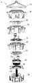
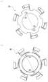
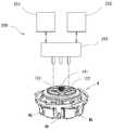
도 1은 본 발명에 관한 로터를 구비한 정제 카세트의 측방 경사 상방으로부터 본 일부 단면 사시도(a), 일부 단면 측면도(b).
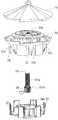
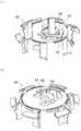
도 2a는 로터의 하방으로부터 본 전체 사시도(a), 평판상의 구획 부재를 갖는 정제 카세트의 부분 단면도(b), 원호상의 구획 부재를 갖는 정제 카세트의 부분 단면도(c).
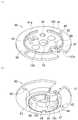
도 2b는 로터의 전체 사시도.
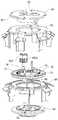
도 3은 도 2b의 로터의 분해 사시도.
도 4는 로터 승강 기구의 분해 사시도.
도 5는 로터 커버의 경사 상방으로부터 본 사시도(a), 및 경사 하방으로부터 본 사시도(b).
도 6a는 로터 커버의 평면도(a), 로터 커버 상의 정제가 이동하는 상황을 도시하는 평면도(b, c).
도 6b는 로터 커버 상의 정제가 이동하는 상황을 도시하는 단면도(a), 다른 실시예에 있어서의 로터 커버 상의 정제가 이동하는 상황을 도시하는 단면도(b).
도 7은 로터 본체의 경사 상방으로부터 본 사시도(a), 및 경사 하방으로부터 본 사시도(b).
도 8은 로터 베이스의 경사 상방으로부터 본 사시도(a), 및 경사 하방으로부터 본 사시도(b).
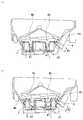
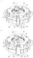
도 9는 로터를 작은 정제용으로 조정한 정제 카세트의 일부 단면 측면도(a), 로터를 큰 정제용으로 조정한 정제 카세트의 일부 단면 측면도(b).
도 10은 정제 지지대 승강 기구의 분해 사시도.
도 11은 로터를 작은 정제용으로 조정한 정제 카세트의 일부 단면 측면도(a), 로터를 큰 정제용으로 조정한 정제 카세트의 일부 단면 측면도(b).
도 12는 가동 부재 이동 기구의 분해 사시도.
도 13은 제1 가동 부재의 경사 상방으로부터 본 사시도(a), 및 경사 하방으로부터 본 사시도(b).
도 14는 제2 가동 부재의 경사 상방으로부터 본 사시도(a), 및 경사 하방으로부터 본 사시도(b).
도 15는 제1 가동 부재(a)와 제2 가동 부재(b)의 평면도.
도 16은 캠 부재의 사시도(a), 평면도(b).
도 17은 제1 지지 부재의 경사 상방으로부터 본 사시도(a), 및 경사 하방으로부터 본 사시도(b).
도 18은 제2 지지 부재의 경사 상방으로부터 본 사시도(a), 및 경사 하방으로부터 본 사시도(b).
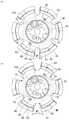
도 19는 작은 정제용으로 조정한 로터의 평면도(a), 큰 정제용으로 조정한 로터의 평면도(b).
도 20은 작은 정제용으로 조정한 로터의 사시도(a), 큰 정제용으로 조정한 로터의 사시도(b).
도 21은 자동 조정 장치의 개략도.
도 22는 가동 부재 이동 기구의 변형예 1을 도시하는 사시도.
도 23은 제1 가동 부재의 경사 하방으로부터 본 사시도(a), 제2 가동 부재의 경사 상방으로부터 본 사시도(b)
도 24는 웜 기구를 갖는 제2 지지 부재의 사시도.
도 25는 가동 부재 이동 기구의 변형예 2에 있어서의 제1 가동 부재(a)와 제2 가동 부재(b)의 평면도.
도 26은 가동 부재 이동 기구의 변형예 3에 있어서의 분해 사시도(a), 조정 나사의 정면도(b).
도 27은 도 26의 가동 부재 이동 기구의 제1 가동 부재측으로부터 본 평면도(a), 제2 가동 부재측으로부터 본 저면도(b).
도 28은 로터 본체의 변형예를 도시하는 분해 사시도.BRIEF DESCRIPTION OF THE DRAWINGS Fig. 1 is a partial sectional perspective view (a) and a partial sectional side view (b) of a tablet cassette having a rotor according to the present invention, seen from above obliquely from the side;
Fig. 2A is an overall perspective view (a) of the rotor seen from below, a partial cross-sectional view of a tablet cassette having a plate-shaped partition member (b), and a partial cross-sectional view of a tablet cassette having an arc-shaped partition member (c).
2B is an overall perspective view of the rotor;
Figure 3 is an exploded perspective view of the rotor of Figure 2b.
Fig. 4 is an exploded perspective view of a rotor lifting mechanism;
Fig. 5 is a perspective view (a) of the rotor cover seen from obliquely upward, and a perspective view (b) seen from obliquely downward.
6A is a plan view (a) of a rotor cover, and a plan view (b, c) showing a situation in which tablets on the rotor cover are moved.
Fig. 6B is a cross-sectional view (a) showing a situation in which tablets on the rotor cover move, and a cross-sectional view (b) showing a situation in which tablets on the rotor cover move in another embodiment.
Fig. 7 is a perspective view (a) of the rotor body seen from obliquely upward, and a perspective view (b) seen from obliquely downward.
Fig. 8 is a perspective view (a) of the rotor base seen from obliquely upward, and a perspective view (b) seen from obliquely downward.
9 is a partial cross-sectional side view of a tablet cassette with the rotor adjusted for small tablets (a), and a partial cross-sectional side view of a tablet cassette with the rotor adjusted for large tablets (b).
10 is an exploded perspective view of the tablet support lifting mechanism;
11 is a partial cross-sectional side view of a tablet cassette with the rotor adjusted for small tablets (a), and a partial cross-sectional side view of a tablet cassette with the rotor adjusted for large tablets (b).
12 is an exploded perspective view of a movable member moving mechanism;
Fig. 13 is a perspective view (a) of the first movable member seen from above obliquely, and a perspective view (b) seen from below obliquely.
Fig. 14 is a perspective view (a) of the second movable member seen from obliquely upward, and a perspective view (b) seen from obliquely downward.
Fig. 15 is a plan view of a first movable member (a) and a second movable member (b);
16 is a perspective view (a) and a plan view (b) of the cam member.
Fig. 17 is a perspective view (a) of the first support member seen from obliquely upward, and a perspective view (b) seen from obliquely downward.
Fig. 18 is a perspective view (a) of the second support member seen from obliquely upward, and a perspective view (b) seen from obliquely downward.
19 is a plan view (a) of a rotor adjusted for small refining, and a plan view (b) of a rotor adjusted for large refining.
Fig. 20 is a perspective view of a rotor adjusted for small tablets (a), and a perspective view of a rotor adjusted for large tablets (b).
21 is a schematic diagram of an automatic adjustment device;
Fig. 22 is a perspective view showing a first modification of the movable member moving mechanism;
Fig. 23 is a perspective view (a) of the first movable member as seen from an obliquely downward direction, and a perspective view (b) of the second movable member as seen from an obliquely upward direction;
24 is a perspective view of a second support member having a worm mechanism;
Fig. 25 is a plan view of a first movable member (a) and a second movable member (b) according to a second modification of the movable member moving mechanism;
Fig. 26 is an exploded perspective view (a) and a front view (b) of an adjustment screw in a third modification of the movable member moving mechanism;
Fig. 27 is a plan view (a) of the movable member moving mechanism of Fig. 26 seen from the first movable member side, and a bottom view (b) of the movable member moving mechanism of Fig. 26 viewed from the second movable member side.
Fig. 28 is an exploded perspective view showing a modified example of the rotor body;
이하, 본 발명의 실시 형태를 첨부 도면에 따라서 설명한다.EMBODIMENT OF THE INVENTION Hereinafter, embodiment of this invention is described according to an accompanying drawing.
도 1은 정제 수납 불출 장치에 장착되는 정제 카세트(1)를 도시한다. 정제 카세트(1)는 베이스(2) 위에 설치된 카세트 본체(3)와, 해당 카세트 본체(3)에 수용된 본 발명에 관한 로터(4)로 이루어져 있다.1 shows a
카세트 본체(3)는 다수의 정제 T를 수용 가능한 정제 수용부(5)와, 이 정제 수용부(5)보다 하방에 설치되며, 로터(4)를 수용하는 로터 수용부(6)로 구성되어 있다. 정제 수용부(5)의 상단은 개구되고, 도시하지 않은 덮개로 개폐 가능하게 되어 있다. 로터 수용부(6)는 역원추형의 상부 경사 내면(6a)과, 원통형의 하부 수직 내면(6b)과, 저면(6c)을 갖고 있다. 상부 경사 내면(6a)의 하부로부터 저면(6c)에 걸쳐 정제 배출 구멍(7)이 형성되어 있다. 정제 배출 구멍(7)은 베이스(2)에 형성된 정제 배출로(2a)에 연통하고 있다. 카세트 본체(3)의 외측에는, 구획 부재(8)가 설치되고, 해당 구획 부재(8)의 선단은 로터 수용부(6)의 외측으로부터 내측에 삽입되어 있다. 저면(6c)의 중앙에는 로터축 구멍(9)이 형성되어 있다.The
구획 부재(8)는, 도 2a의 (a)에 도시한 바와 같이, 상면이 볼록한 원호상으로 형성되어 있다. 도 2a의 (b)에 도시한 바와 같이, 구획 부재(8')가 원호상이 아니라 평판상으로 형성되어, 구획 부재(8')와 정제 안내로(4b)의 최하위의 정제 T 사이의 간극 S'가 좁은 경우, 정제 T가 구획 부재(8')에 걸려, 낙하하지 못하는 경우가 있다. 이 경우, 정제 T의 낙하를 가능하게 하기 위해, 2점 쇄선으로 나타내는 바와 같이 구획 부재(8')를 높게 하면, 구획 부재(8')가 아래로부터 2번째의 정제에 닿아 최하위의 정제와 아래로부터 2번째의 정제를 원활하게 구획할 수 없다. 본 실시 형태에서는, 구획 부재(8)가 위로 볼록한 원호상으로 형성되어 있으므로, 도 2a의 (c)에 도시한 바와 같이, 구획 부재(8)의 중앙부가 높아져, 구획 부재(8)와 정제 안내로(4b)의 최하위의 정제 T 사이의 간극 S가 넓어져, 최하위의 정제 T가 구획 부재(8)에 걸리는 일 없이 낙하할 수 있는 한편, 도 2a의 (a)에 도시한 바와 같이, 구획 부재(8)의 양단이 중앙부보다 낮아져, 최하위의 정제 T1과 아래로부터 2번째의 정제 T2를 원활하게 구획할 수 있다는 2개의 기능을 충분히 발휘할 수 있다.The
로터(4)는, 도 2b에 도시한 바와 같이, 상면이 원추형, 측면이 역원추형, 저면이 평탄한 형상을 갖고 있다. 로터의 측면 상부에는, 주위 방향으로 정제 포켓(4a)이 설치되고, 해당 정제 포켓(4a)으로부터 하방으로 연장되는 복수의 정제 안내로(4b)가 주위 방향으로 등간격으로 설치되어 있다.As shown in Fig. 2B, the
정제 포켓(4a)은 후술하는 로터 본체(20)의 외주면과, 후술하는 제1 가동 부재(50)의 제1 수평 돌기(54)와 제2 가동 부재(60)의 제2 수평 돌기(64)로 형성되고, 카세트 본체(3)의 상부 경사 내면(6a)에 둘러싸이며, 카세트 본체(3)의 정제 수용부(5)의 정제 T를 수용하여 주위 방향으로 정렬시킨다.The
정제 안내로(4b)는 후술하는 로터 본체(20)의 하향 돌기부(22)의 하부 경사 외면(22c)과, 후술하는 제1 가동 부재(50)의 제1 수직 돌기(53), 후술하는 제2 가동 부재(60)의 제2 수직 돌기(63)와, 후술하는 환상 승강 부재(45)의 정제 지지대(47)로 형성되고, 카세트 본체(3)의 상부 경사 내면(6a)에 덮이며, 정제 포켓(4a)에 정렬되어 있는 정제 T를 수용하여 하방으로 안내한다.The
도 3은 분해 상태의 로터(4)를 도시한다. 로터(4)는 주로, 로터 커버(10), 로터 본체(20), 로터 베이스(30), 통상 회전 부재(40), 환상 승강 부재(45), 제1 가동 부재(50), 제2 가동 부재(60), 캠 부재(70), 제1 지지 부재(80), 제2 지지 부재(90), 두께 조정 나사(101)와, 높이 조정 나사(102)와, 폭 조정 나사(103)를 갖고, 이들에 의해 이하에 설명하는 로터 승강 기구, 정제 지지대 승강 기구, 가동 부재 이동 기구가 구성되어 있다.3 shows the
<로터 승강 기구><Rotor elevating mechanism>
도 4는 로터 승강 기구를 구성하는 부재를 도시한다. 로터 승강 기구는, 로터 커버(10)와, 로터 본체(20)와, 로터 베이스(30)와, 두께 조정 나사(101)로 구성되어 있다.4 shows the members constituting the rotor lifting mechanism. The rotor lifting mechanism includes a
로터 커버(10)는, 도 5에 도시한 바와 같이, 전체적으로 우산 형상을 갖고 있다. 로터 커버(10)의 상면은 원추형, 외주면은 역원추형으로 형성되어 있다. 로터 커버(10)에는, 이하에 설명하는 바와 같이, 카세트 본체(3)에 수용된 정제 T를 정제 포켓(4a)으로 확실하게 유도하는 것을 목적으로 하기 위한 수단이 강구되어 있다. 로터 커버(10)의 상면은, 도 6a의 (a)에 도시한 바와 같이, 중심에 위치하는 노브(11)를 축으로 하는 4개의 부채형 경사면(12)으로 이루어진다. 각 부채형 경사면(12)은 주위 방향의 일단에서는 반경(r1)이 작고, 또한, 경사가 급하고, 주위 방향의 타단에서는 반경(r2)이 크고, 또한, 경사가 완만해지도록 형성되어 있다. 또한, 외주면을 원통형으로 함으로써, 부채형 경사면(12)의 주위 방향 일단의 반경(r1)과, 주위 방향 타단의 반경(r2)을 동일하게 할 수 있다. 또한, 로터 커버(10)의 외주연의 높이는, 로터(4)의 회전 방향[도 6a의 (a)에 있어서 시계 방향]과 반대 방향[도 6a의 (a)에 있어서 반시계 방향]을 향하여 점차적으로 높아지도록 형성되어 있다. 이 때문에, 도 6a의 (b), 도 6a의 (c)에 도시한 바와 같이, 로터(4)가 시계 방향으로 회전하여, 로터 커버(10)의 외주 부근의 반경 r1의 A점에 위치하는 정제 T가, 반경 r2의 B점에 오는 상태를 생각한다. 정제 T는, 카세트 본체(3)의 내면과 접촉하여 저항을 받으므로, 로터(4)의 회전보다 지연되어, 로터 커버(10) 위를 미끄러지면서 이동한다. 정제 T는, 로터(4)의 시계 방향의 회전에 의해, 도 6b의 (a)에 도시한 바와 같이, 로터 커버(10)의 외주연과 정제 T의 접촉점이 A로부터 경사 상방의 B까지 이동한다. 즉, 로터 커버(10)가 시계 방향으로 회전함에 따라서, 정제 T는 로터 커버(10)의 외주연에 의해 상방으로 밀어올려지고, 또한, 외측으로 압출되는 결과, 정제 T는, 2점 쇄선으로 나타내는 바와 같이, 누운 상태로부터 선 상태로 방향이 변화되어, 로터(4)와 카세트 본체(3) 사이의 정제 포켓(4a)에 확실하게 도입된다. 또한, 인접하는 부채형 경사면(12)의 사이에는, 도 5의 (a)에 도시한 바와 같이, 반경 방향 외측을 향함에 따라서 커지는 단차(13)가 형성되어 있다. 이 단차(13)에 의해, 카세트 본체(3)에 수용된 정제 T를 교반할 수 있다. 또한, 로터 커버(10)의 외주의 큰 단차(13)에 의해, 도 6b의 (a)에 도시한 바와 같이, 정제 T를 누운 상태로부터 선 상태로 방향을 변화시킬 수 있어, 정제 T를 정제 포켓(4a)으로 유도할 수 있다. 또한, 부채형 경사면(12)은 4개 형성되어 있지만, 그 수는 한정되지 않고, 2개, 3개여도 된다.As shown in FIG. 5, the
로터 커버(10)의 정제 유도 수단에 의해, 카세트 본체(3)에 수용된 정제 T를 확실하게 정제 포켓(4a)으로 유도하고, 각 정제 안내로(4b)를 통해 정제 배출 구멍(7)으로 안내하여, 배출할 수 있으므로, 각 정제 안내로(4b)로부터 1개씩 일정한 시간 간격으로, 단시간에 원활하게 소요 개수의 정제 T를 배출할 수 있다는 효과를 갖고 있다. 또한, 로터 커버(10)의 정제 유도 수단은, 로터 승강 기구, 정제 지지대 승강 기구 및 가동 부재 이동 기구에 의한 정제 안내로의 조정 방법이 없는 일반의 로터에도 적용 가능하다. 또한, 이 정제 유도 수단은 로터 본체(20)의 외면이 역원추상이 아니라, 원통상이어도 적용 가능하다. 즉, 도 6b의 (b)에 도시한 바와 같이, 로터 커버(10)의 역원추상의 외주면으로부터 하방의 로터 본체(20)의 외주면이 원통상이며, 정제 안내로(4b)가 연직 방향으로 연장되어 있어도 이미 설명한 바와 같이, 로터 커버(10)의 부채형 경사면(12)의 작용에 의해, 정제 T를 정제 포켓(4a)으로 확실하게 유도할 수 있다.The tablets T accommodated in the
도 5의 (a)에 도시한 바와 같이, 로터 커버(10)의 외주면의 하단은, 톱니상으로 형성되고, 주위 6개소에 걸림 결합 단차(14)가 형성되어 있다. 로터 커버(10)의 내면에는, 도 5의 (b)에 도시한 바와 같이, 환상 리브(15)가 형성되어 있다. 환상 리브(15)의 내측에는, 후술하는 로터 본체(20)의 영구 자석(27)이 흡착되는 자성체의 금속판(16)이 설치되어 있다.As shown in Fig. 5(a), the lower end of the outer peripheral surface of the
로터 본체(20)는, 도 7에 도시한 바와 같이, 원형의 기부(21)와, 하향 돌기부(22)와, 환상부(23)와, 가이드부(24)를 갖고 있다.As shown in FIG. 7 , the
기부(21)에는 그 하면 중앙으로부터 하방으로 돌출되는 축부(25)가 설치되고, 해당 축부(25)에 나사 구멍(25a)이 형성되어 있다. 기부(21)의 상면에는, 로터 커버(10)의 환상 리브(15)의 내측에 끼워 맞추는 환상 리브(26)와, 후술하는 높이 조정 나사(102)와 폭 조정 나사(103)가 노출되는 2개의 구멍(21a, 21b)이 형성되어 있다. 기부(21)의 상면의 2개소에는, 로터 커버(10)의 금속판(16)에 흡착되는 영구 자석(27)이 장착되어 있다.A
하향 돌기부(22)는 기부(21)의 외주연의 6등배 위치로부터 하방으로 연장되어 있다. 하향 돌기부(22)는 수직인 내면(22a)과, 기부(21)의 외주연으로부터 외측으로 하향으로 경사지는 상부 경사 외면(22b)과, 해당 상부 경사 외면(22b)의 하단으로부터 내측으로 하향으로 경사지는 하부 경사 외면(22c)으로 이루어지고, 측면으로부터 보아 삼각형으로 형성되어 있다. 하부 경사 외면(22c)은 정제 안내로(4b)의 저면을 형성하고 있다. 하향 돌기부(22)의 하단에는 슬릿(22d)이 형성되어 있다.The
환상부(23)는 기부(21)의 외측에 동심으로 형성되며, 하향 돌기부(22)를 통해 기부(21)와 접속되어 있다. 환상부(23)의 외면은, 로터 커버(10)의 외주면과 연속하는 역원추형으로 형성되어 있다. 환상부(23)의 상단은 톱니상으로 형성되며, 로터 커버(10)의 걸림 결합 단차(14)와 걸림 결합하여 로터 커버(10)를 주위 방향으로 위치 결정하는 단차부(28)가 형성되어 있다.The
가이드부(24)는 하향 돌기부(22)의 사이에서, 또한, 환상부(23)의 내주연의 주위 6등배 위치로부터 하방으로 연장되어 있다. 가이드부(24)의 내면에는, 후술하는 로터 베이스(30)의 가이드편(32)이 슬라이드 가능하게 걸림 결합하는 가이드 홈(24a)이 형성되어 있다. 가이드편(32)과 가이드 홈(24a)이 걸림 결합함으로써, 로터 베이스(30)와 로터 본체(20)는 일체적으로 회전한다.The
로터 베이스(30)는, 도 8에 도시한 바와 같이, 원형의 기부(31)와, 가이드편(32)과, 구동축(33)을 갖고 있다.As shown in FIG. 8 , the
기부(31)의 상면에는, 중앙에 원형 돌기부(34)와, 그 외측에 환상벽(35)이 형성되어 있다. 원형 돌기부(34)의 중심에 후술하는 두께 조정 나사(101)를 지지하는 오목부(34a)가 형성되어 있다. 오목부(34a)의 옆에는, 두께 조정 나사(101)의 자유로운 회전을 방지하는 스토퍼(36)를 수용하는 구멍(34b)과, 후술하는 제2 지지 부재(90)의 2개의 나사 삽입 관통 구멍(100)에 삽입 관통된 도시하지 않은 나사가 나사 결합하는 2개의 나사 구멍(34c)이 형성되어 있다. 원형 돌기부(34)와 환상벽(35) 사이에는 후술하는 정제 지지대 승강 기구를 수용하는 환상 오목부(37)가 형성되어 있다. 환상벽(35)에는, 주위 6등배 위치에 축 방향으로 연장되는 수직 슬릿(35a)이 형성되고, 이 수직 슬릿(35a)은 기부(31)의 환상 오목부(37)로부터 외주연까지 방사상으로 형성한 수평 슬릿(31a)과 연속하고 있다. 환상벽(35)의 외주면에는 복수의 보강 리브(35b)가 요소에 설치되어 있다. 기부(31)의 하면에는, 도 8의 (b)에 도시한 바와 같이, 중앙에 오목부(31b)가 형성되어 있다.On the upper surface of the
가이드편(32)은 기부(31)의 외주연의 주위 6등배 위치이며, 또한, 인접하는 수평 슬릿(31a)의 사이에, 상방으로 돌출되어 있다. 가이드편(32)은 로터 본체(20)의 가이드부(24)의 가이드 홈(24a)에 슬라이드 가능하게 걸림 결합하도록 형성되어 있다.The
구동축(33)은 기부(31)의 하면의 오목부(31b)의 바닥 중앙으로부터 축 방향으로 연장되어 있다. 이 구동축(33)에는 도 1에 도시한 구동 기어(33a)가 설치되고, 베이스(2)에 설치한 도시하지 않은 모터에 의해 회전 구동하도록 되어 있다.The
두께 조정 나사(101)는, 도 4에 도시한 바와 같이, 수나사부(101a)와 하단의 기어부(101b)를 갖고 있다. 수나사부(101a)는 로터 본체(20)의 나사 구멍(25a)에 나사 결합하고, 하단의 기어부(101b)는 로터 베이스(30)의 기부(31)의 오목부(34a)에 수용 지지되고, 수나사부(101a)의 상단은 로터 본체(20)의 나사 구멍(25a)으로부터 돌출되어 노출되어, 외부로부터 회전 조정 가능하게 되어 있다. 기어부(101b)의 치간에는 탄성편으로 이루어지는 스토퍼(36)의 선단이 걸림 지지되어 있다. 두께 조정 나사(101)의 하단의 기어부(101b)는, 후술하는 가동 부재 이동 기구의 제2 지지 부재(90)의 구멍(96)보다도 크게 형성되어, 두께 조정 나사(101)가 제2 지지 부재(90)로부터 상방으로 빠지지 않도록 되어 있다.The
<정제 지지대 승강 기구><Tablet Support Elevating Mechanism>
도 10은 정제 지지대 승강 기구를 구성하는 부재를 도시한다. 정제 지지대 승강 기구는, 통상 회전 부재(40)와, 환상 승강 부재(45)와, 높이 조정 나사(102)로 구성되어 있다.10 shows the members constituting the tablet support lifting mechanism. The tablet support raising/lowering mechanism is comprised by the
통상 회전 부재(40)는 외주 하부에 수나사부(41)가 형성되고, 내주 상부에 종동 기어(42)가 형성되어 있다. 종동 기어(42)에는 통상 회전 부재(40)의 자유로운 회전을 방지하는 스토퍼(43)가 걸림 결합하고 있다.In general, the rotating
환상 승강 부재(45)는 외주의 6등배 위치에 방사상으로 아암(46)이 돌출 설치되고, 각 아암(46)의 선단에 정제 지지대(47)가 형성되어 있다. 정제 지지대(47)는 정제 안내로(4b) 내의 최하위의 정제 T를 지지할 수 있도록, 정제 안내로(4b)에 직교하는 경사면(47a)을 갖고 있다. 환상 승강 부재(45)의 내면에는 통상 회전 부재(40)의 수나사부(41)와 나사 결합하는 암나사부가 형성되어 있다.The annular lifting and lowering
높이 조정 나사(102)는 하단에 통상 회전 부재(40)의 종동 기어(42)에 맞물리는 구동 기어(102a)를 갖고 있다. 높이 조정 나사(102)의 상단은, 로터 본체(20)의 기부(21)의 상면의 구멍(21a)으로부터 돌출되어 노출되어, 외부로부터 회전 조정 가능하게 되어 있다.The
통상 회전 부재(40)와 환상 승강 부재(45)는 서로 나사 결합한 상태에서, 로터 베이스(30)의 환상 오목부(37)에 수용되고, 환상 승강 부재(45)의 아암(46)이 로터 베이스(30)의 수직 슬릿(35a)에 슬라이드 가능하게 끼워 넣어지고, 정제 지지대(47)가 로터 베이스(30)의 환상벽(35)의 외측으로 돌출되어, 정제 안내로(4b) 내의 최하위의 정제 T를 지지하도록 되어 있다.The normal rotating
<가동 부재 이동 기구><Movable member moving mechanism>
도 12는 가동 부재 이동 기구를 구성하는 부재를 도시한다. 가동 부재 이동 기구는, 제1 가동 부재(50)와, 제2 가동 부재(60)와, 캠 부재(70)와, 제1 지지 부재(80)와, 제2 지지 부재(90)와, 폭 조정 나사(103)로 구성되어 있다.12 shows the members constituting the movable member moving mechanism. The movable member moving mechanism includes a first
도 13에 도시한 바와 같이, 제1 가동 부재(50)는 원환상의 기부(51)와, 6개의 벽부(52)와, 제1 수직 돌기(53)와, 제1 수평 돌기(54)를 갖고 있다. 기부(51)에는, 180도 이격된 위치에 2개의 제1 조정 구멍(55)이 형성되어 있다. 제1 조정 구멍(55)은, 도 15의 (a)에 도시한 바와 같이, 긴 구멍이며, 그 중심선은 제1 가동 부재(50)의 중심을 통과하는 반경 방향의 선에 대하여 60도 경사져 있다. 도 13으로 되돌아가면, 기부(51)의 외주연의 주위 6등배 위치에, 로터 본체(20)의 하향 돌기부(22)가 걸림 결합하는 노치(51a)가 형성되어 있다. 기부(51)의 하면에는, 궁형의 가이드부(56)가 환상으로 배치되어 있다. 6개의 벽부(52)는 기부(51)의 외주연의 주위 6등배 위치이며, 또한, 정면으로부터 보아 좌측의 노치(51a)측으로 치우친 위치로부터 하향으로 돌출되어 있다. 제1 수직 돌기(53)는 벽부(52)의 정면으로부터 보아 좌측단으로부터 외측으로 돌출되어, 전술한 정제 안내로(4b)의 우측면을 형성하는 것이다. 제1 수직 돌기(53)에는 구획 부재(8)가 끼워 넣어지는 노치(53a)가 형성되어 있다. 제1 수평 돌기(54)는 제1 수직 돌기(53)의 상단으로부터 주위 방향으로 수평으로 정면으로부터 보아 우측을 향하여 연장되어, 전술한 정제 포켓(4a)의 저면을 형성하는 것이다. 제1 수평 돌기(54)의 선단부 상면은 선단을 향하여 하향의 테이퍼(54a)가 형성되어 있다.As shown in FIG. 13 , the first
도 14에 도시한 바와 같이, 제2 가동 부재(60)는 원환상의 기부(61)와, 6개의 벽부(62)와, 제2 수직 돌기(63)와, 제2 수평 돌기(64)를 갖고 있다. 기부(61)에는, 180도 이격된 위치에 2개의 제2 조정 구멍(65)이 형성되어 있다. 제2 조정 구멍(65)은, 도 15의 (b)에 도시한 바와 같이, 긴 구멍이며, 그 중심선은, 제1 가동 부재(50)의 제1 조정 구멍(55)과 교차하는 방향에서, 제2 가동 부재(60)의 중심을 통과하는 반경 방향의 선에 대하여 60도 경사져 있다. 도 14로 되돌아가면, 기부(61)의 외주연의 주위 6등배 위치에, 로터 본체(20)의 하향 돌기부(22)가 걸림 결합하는 노치(61a)가 형성되어 있다. 기부(61)의 상면에는, 궁형의 가이드부(66)가 환상으로 배치되어 있다. 6개의 벽부(62)는 기부(61)의 외주연의 주위 6등배 위치이며, 또한, 정면으로부터 보아 우측의 노치(61a)측으로 치우친 위치로부터 하향으로 돌출되어 있다. 제2 수직 돌기(63)는 벽부의 정면으로부터 보아 우측단으로부터 외측으로 돌출되어, 전술한 정제 안내로(4b)의 좌측면을 형성하는 것이다. 제2 수직 돌기(63)에는 구획 부재(8)가 끼워 넣어지는 노치(63a)가 형성되어 있다. 제2 수평 돌기(64)는 제2 수직 돌기(63)의 상단으로부터 주위 방향으로 수평으로 정면으로부터 보아 좌측을 향하여 연장되어, 제1 가동 부재(50)의 제1 수평 돌기(54)와 함께, 전술한 정제 포켓(4a)의 저면을 형성하는 것이다. 제2 가동 부재(60)의 제2 수평 돌기(64)의 선단부는, 제1 가동 부재(50)의 제1 수평 돌기(54)의 선단부의 아래에 겹치도록 형성되어 있다.As shown in FIG. 14 , the second
도 16에 도시한 바와 같이, 캠 부재(70)는 원환 형상을 갖고, 제1 가동 부재(50)와 제2 가동 부재(60) 사이에 배치되며, 제1 가동 부재(50)의 하면의 가이드부(56)와 제2 가동 부재(60)의 상면의 가이드부(66)에 가이드되어 회전 가능하게 되어 있다. 캠 부재(70)의 내주에는 종동 기어(71)가 형성되고, 내주와 외주 사이에는 2개의 원호상의 캠 홈(72)이 형성되어 있다. 종동 기어(71)에는, 캠 부재(70)의 자유로운 회전을 방지하는 스토퍼(73)가 걸림 결합되어 있다. 캠 홈(72)의 일단으로부터 타단까지의 각도는 약 140°이지만, 이것에 한정되는 것은 아니다. 캠 홈(72)은, 도 16의 (b)에 도시한 바와 같이, 평면을 보아 시계 방향으로 진행함에 따라서 외주연에 접근하도록 형성되어 있다. 각 캠 홈(72)에는 구동 핀(74)이 삽입 관통되어 있다.As shown in FIG. 16 , the
도 17에 도시한 바와 같이, 제1 지지 부재(80)는 원형의 기부(81)의 하면에 원형의 돌기부(82)를 갖고 있다. 기부(81)에는 180° 이격된 위치에 2개의 제1 가이드 구멍(83)이 형성되어 있다. 제1 가이드 구멍(83)은 긴 구멍이며, 제1 지지 부재(80)의 중심을 통과하는 반경 방향으로 연장되어 있다. 제1 가이드 구멍(83)에는 구동 핀(74)의 상단이 끼워 맞추어져 있다. 기부(81)의 외주연의 주위 6등배 위치에, 로터 본체(20)의 하향 돌기부(22)가 걸림 결합하는 노치(81a)가 형성되어 있다. 기부(81)의 중앙에는, 로터 승강 기구의 두께 조정 나사(101)가 관통하는 구멍(84)과, 정제 지지대 승강 기구의 높이 조정 나사(102)가 관통하는 구멍(85)과, 후술하는 폭 조정 나사(103)가 관통하는 구멍(86)과, 2개의 나사 삽입 관통 구멍(87)이 형성되어 있다.As shown in FIG. 17 , the first supporting
도 18에 도시한 바와 같이, 제2 지지 부재(90)는 원형의 기부(91)의 상면에, 제1 지지 부재(80)의 원형의 돌기부(82)가 끼워 맞추어지는 환상 돌기부(92)가 형성되어 있다. 기부(91)의 하면에 원형의 대돌기부(93)와 소돌기부(94)를 갖고 있다. 대돌기부(93)와 소돌기부(94)는 전술한 정제 지지대 승강 기구의 통상 회전 부재(40)에 끼워 넣어지는 크기를 갖고 있다. 상면의 환상 돌기부(92)의 외측에는, 180° 이격된 위치이며, 제1 지지 부재(80)의 제1 가이드 구멍(83)과 대응하는 위치에, 제2 가이드 구멍(95)이 형성되어 있다. 제2 가이드 구멍(95)은 긴 구멍이며, 제2 지지 부재(90)의 중심을 통과하는 반경 방향으로 연장되어 있다. 제2 가이드 구멍(95)에는 구동 핀(74)의 하단이 끼워 맞추어져 있다. 기부(91)의 중앙에는, 로터 승강 기구의 두께 조정 나사(101)가 관통하는 구멍(96)과, 정제 지지대 승강 기구의 높이 조정 나사(102)가 관통하는 구멍(97) 및 노치(97a)와, 후술하는 폭 조정 나사(103)의 지지축(103b)이 관통하는 구멍(98)과, 제1 지지 부재(80)의 2개의 나사 삽입 관통 구멍(87)에 삽입 관통되는 도시하지 않은 나사가 나사 결합하는 2개의 나사 구멍(99)과, 2개의 나사 삽입 관통 구멍(100)이 형성되어 있다. 또한, 기부(91)에는, 정제 지지대 승강 기구의 스토퍼(43)가 끼워 맞추어지는 관통 구멍(91a)이 형성되어 있다.As shown in FIG. 18 , the second supporting
제1 지지 부재(80)의 나사 삽입 관통 구멍(87)으로부터 제2 지지 부재(90)의 나사 구멍(99)에 도시하지 않은 나사를 삽입하여 체결함으로써, 제1 지지 부재(80)와 제2 지지 부재(90)는 제1 가동 부재(50), 제2 가동 부재(60) 및 캠 부재(70)를 끼움 지지한 상태에서 일체로 되어 있다.The
또한, 제2 지지 부재(90)의 나사 삽입 관통 구멍(100)으로부터 로터 베이스(30)의 나사 구멍(34c)에 도시하지 않은 나사를 삽입하여 체결함으로써, 제2 지지 부재(90)가 로터 베이스(30)에 고정됨과 함께, 제2 지지 부재(90)와 로터 베이스(30) 사이에 정제 지지대 승강 기구의 통상 회전 부재(40)가 보유 지지되어, 축 방향의 이동이 구속된다.In addition, by inserting and fastening a screw (not shown) from the
폭 조정 나사(103)는, 도 16에 도시한 바와 같이, 중간에 캠 부재(70)의 종동 기어(71)에 맞물리는 구동 기어(103a)를 갖고, 하단은 지지축(103b)이 돌출 설치되어 있다. 폭 조정 나사(103)의 상단은, 로터 본체(20)의 기부(21)의 상면의 구멍(21b)으로부터 돌출되어 노출되어, 외부로부터 회전 조정 가능하게 되어 있다.As shown in FIG. 16, the
다음에, 이상의 구성으로 이루어지는 정제 카세트(1)에 있어서의 로터(4)의 동작을 설명한다.Next, the operation of the
도 2b를 참조하여 이미 설명한 바와 같이, 카세트 본체(3)와 로터(4) 사이에는, 로터(4)의 측면 상부에 주위 방향으로 연장되는 정제 포켓(4a)과, 로터(4)의 측면 상부로부터 하방으로 연장되는 복수의 정제 안내로(4b)를 갖고 있다.As already described with reference to FIG. 2B , between the
정제 포켓(4a)은 로터 본체(20)의 외주면에 의해 형성되는 외주 측면과, 제1 가동 부재(50)의 제1 수평 돌기(54) 및 제2 가동 부재(60)의 제2 수평 돌기(64)에 의해 형성되는 주위 방향으로 등간격으로 배치된 저면으로 구성되어 있다.The
정제 안내로(4b)는 로터 본체(20)의 하향 돌기부(22)의 하부 경사 외면(22c)에 의해 형성되는 저면과, 제1 가동 부재(50)의 제1 수직 돌기(53)에 의해 형성되는 우측면과, 제2 가동 부재(60)의 제2 수직 돌기(63)에 의해 형성되는 좌측면과, 정제 지지대(47)에 의해 형성되는 하단부면으로 구성되어 있다. 정제 안내로(4b)는 인접하는 정제 포켓(4a)으로부터 로터(4)의 저면을 향하여 연장되어 있다.The
도 1의 (a)를 참조하면, 카세트 본체(3)의 정제 수용부(5)에 수용된 정제 T는, 로터(4)의 회전에 의해, 로터 커버(10)의 단차(13)에 의해 교반되면서 정제 포켓(4a)에 진입하고, 정제 포켓(4a)으로부터 정제 안내로(4b)에 진입하고, 정제 안내로(4b)가 정제 배출 구멍(7)에 근접하면, 정제 안내로(4b)의 최하위의 정제 T와 그것보다 상측의 정제 T 사이에 카세트 본체(3)에 고정된 구획 부재(8)가 진입한다. 구획 부재(8)보다 상방의 정제 T는 구획 부재(8)에 의해 하방으로 낙하하는 것이 저지된다. 구획 부재(8)보다 하방의 최하위의 정제 T는, 정제 지지대(47)에 있지만, 정제 지지대(47)는 경사면(47a)으로 되어 있으므로, 당해 경사면(47a) 위에서 정제 배출구(7)를 향하여 쓰러져, 정제 배출 구멍(7)으로부터 배출된다. 정제 배출 구멍(7)으로부터 배출된 정제 T는, 베이스(2)의 정제 배출로(2a)를 지나 불출된다. 이에 의해, 정제 안내로(4b)가 정제 배출 구멍(7)으로 돌아올 때마다, 정제 T가 1개씩 배출된다. 로터(4)의 회전 각도를 조정함으로써, 처방에 따른 수의 정제 T를 불출할 수 있다.Referring to Figure 1 (a), the tablet T accommodated in the
정제 안내로(4b)는 전술한 로터 승강 기구, 정제 지지대 승강 기구, 가동 부재 이동 기구를 사용하여, 정제 T의 두께에 상당하는 깊이 D, 정제의 높이에 상당하는 구획 위치 H, 정제 T의 폭에 상당하는 폭 W를 조정할 수 있다. 이 때문에, 카세트 본체(3)에 수용하는 정제 T의 형상과 크기에 따라서, 적절한 크기의 정제 안내로(4b)로 할 수 있다. 정제 T가 상이할 때마다, 정제 카세트(1) 전체 또는 로터(4)를 교환하지 않고, 동일한 정제 카세트(1) 또는 로터(4)를 사용하여, 다양한 정제 T에 맞춘 정제 안내로(4b)로 조정함으로써, 배출할 수 있다.The
<정제 안내로의 깊이(두께) 조정><Adjusting the depth (thickness) of the tablet guide>
도 9에 도시한 바와 같이, 정제 T의 두께에 상당하는 정제 안내로(4b)의 깊이 D를 조정하기 위해서는, 로터(4)에 자력으로 흡착되어 있는 로터 커버(10)를 떼어내고, 로터 본체(20)의 상면에 노출되어 있는 로터 승강 기구의 두께 조정 나사(101)를 좌측 또는 우측으로 회전시킨다.9, in order to adjust the depth D of the
도 4를 참조하면, 두께 조정 나사(101)는 기어부(101b)가 제2 지지 부재(90)와 로터 베이스(30)에 의해 축 방향의 이동이 구속되고, 또한 로터 본체(20)의 가이드 홈(24a)이 로터 베이스(30)의 가이드편(32)과 걸림 결합함으로써 로터 본체(20)가 로터 베이스(30)에 대하여 회전하는 것이 구속되어 있으므로, 두께 조정 나사(101)를 회전시키면, 두께 조정 나사(101)의 수나사부(101a)와 나사 결합하는 나사 구멍(25a)을 갖는 로터 본체(20)가 로터(4)의 회전축 방향으로 상승 또는 하강한다. 이것에 수반하여, 정제 안내로(4b)의 저면을 형성하는 로터 본체(20)의 하향 돌기부(22)의 하부 경사 외면(22c)도 상승 또는 하강한다.Referring to FIG. 4 , in the
도 9를 참조하면, 하향 돌기부(22)의 하부 경사 외면(22c)은 위로부터 아래를 향함에 따라서 직경 방향으로 외측으로부터 내측을 향하여 경사지며, 카세트 본체(3)의 로터 수용부(6)의 역원추상의 상부 경사 내면(6a)과 평행하게 되어 있다. 이 때문에, 도 9의 (a)에 도시한 바와 같이, 로터 본체(3)의 하향 돌기부(22)의 하부 경사 외면(22c)이 하강하면, 하향 돌기부(22)의 하부 경사 외면(22c)과 카세트 본체(3)의 역원추상의 상부 경사 내면(6a) 사이의 거리가 축소되어, 정제 안내로(4b)의 깊이를 얕게(D1) 할 수 있다. 반대로, 도 9의 (b)에 도시한 바와 같이, 로터 본체(3)의 하향 돌기부(22)의 하부 경사 외면(22c)이 상승하면, 하향 돌기부(22)의 하부 경사 외면(22c)과 카세트 본체(3)의 역원추상의 상부 경사 내면(6a) 사이의 거리가 확대되어, 정제 안내로(4b)의 깊이를 깊게(D2) 할 수 있다. 이와 같이, 두께 조정 나사(101)를 좌측 또는 우측으로 회전함으로써, 정제 안내로(4b)를 통과하는 정제 T의 두께에 따라서, 정제 안내로(4b)의 깊이를 조정할 수 있다. 또한, 도 4에 도시한 두께 조정 나사(101)의 기어부(101b)가 회전할 때마다, 스토퍼(36)의 선단이 기어부(101b)의 이를 타고 넘어 치간에 걸림 결합하므로, 두께 조정 나사(101)를 적당한 위치에서 멈추어, 로터 본체(20)를 원하는 높이 위치에 고정할 수 있다.Referring to FIG. 9 , the lower inclined
<정제 안내로의 구획 위치(높이) 조정><Adjusting the compartment position (height) of the tablet guideway>
도 11에 도시한 바와 같이, 정제 T의 높이에 상당하는 정제 안내로(4b)의 구획 위치 H를 조정하기 위해서는, 도 10에 있어서, 로터 본체(20)의 상면에 노출되어 있는 정제 지지대 승강 기구의 높이 조정 나사(102)를 좌측 또는 우측으로 회전시킨다. 본 발명에서는, 구획 부재(8)는 카세트 본체(3)에 고정되어 있으므로, 정제 안내로(4b)의 구획 위치 H를 조정하는 데, 구획 부재(8) 자체를 이동시키는 것이 아니라, 구획 부재(8)의 하방에 있는 정제 지지대(47)를 승강시켜, 구획 부재(8)와 정제 지지대(47) 사이의 거리를 조정함으로써, 상대적으로 정제 T의 구획 위치 H를 조정하는 것이다.As shown in FIG. 11 , in order to adjust the division position H of the
도 10을 참조하면, 높이 조정 나사(102)의 구동 기어(102a)가 통상 회전 부재(40)의 종동 기어(42)에 맞물려 있으므로, 높이 조정 나사(102)를 회전시키면, 통상 회전 부재(40)가 회전한다. 통상 회전 부재(40)는 제2 지지 부재(90)와 로터 베이스(30)에 의해 상하의 이동이 구속되어 있다. 통상 회전 부재(40)의 수나사부(41)에 나사 결합하는 암나사부(48)를 갖는 환상 승강 부재(45)는 아암(46)이 로터 베이스(30)의 환상벽(35)의 수직 슬릿(35a)을 관통하고 있어 회전이 구속되어 있다. 이 때문에, 통상 회전 부재(40)의 회전에 의해, 환상 승강 부재(45)가 승강하고, 환상 승강 부재(45)의 정제 지지대(47)가 승강한다.10, since the
즉, 도 11의 (a)에 도시한 바와 같이, 통상 회전 부재(40)가 한쪽으로 회전하면, 환상 승강 부재(45)의 정제 지지대(47)가 상승하여, 정제 지지대(47)에 대한 구획 부재(8)의 위치, 즉, 구획 위치가 낮게(H1) 된다. 반대로, 도 11의 (b)에 도시한 바와 같이, 통상 회전 부재(40)가 다른 쪽으로 회전하면, 환상 승강 부재(45)의 정제 지지대(47)가 하강하여, 정제 지지대(47)에 대한 구획 부재(8)의 위치, 즉, 구획 위치가 높게(H2) 된다. 또한, 도 10에 도시한 높이 조정 나사(102)의 회전에 의해 통상 회전 부재(40)가 회전할 때마다, 스토퍼(43)의 선단이 통상 회전 부재(40)의 종동 기어(42)의 이를 타고 넘어 치간에 걸림 결합하므로, 높이 조정 나사(102)를 적당한 위치에서 멈추어, 정제 지지대(47)를 원하는 높이 위치에 고정할 수 있다.That is, as shown in FIG. 11A , when the normal rotating
<정제 안내로의 폭 조정><Adjusting the width of the tablet guide>
도 19, 도 20에 도시한 바와 같이, 정제 T의 폭에 상당하는 정제 안내로(4b)의 폭 W를 조정하기 위해서는, 로터 본체(20)의 상면에 노출되어 있는 가동 부재 이동 기구의 폭 조정 나사(103)를 좌측 또는 우측으로 회전시킨다.19 and 20, in order to adjust the width W of the
도 12를 참조하면, 폭 조정 나사(103)의 구동 기어(103a)가 캠 부재(70)의 종동 기어(71)에 맞물려 있으므로, 폭 조정 나사(103)를 회전시키면, 캠 부재(70)가 회전한다. 캠 부재(70)의 회전에 의해, 캠 부재(70)의 캠 홈(72)이 이동하므로, 캠 홈(72)의 에지가 구동 핀(74)을 압박한다. 구동 핀(74)은 제1 지지 부재(80)의 제1 가이드 구멍(83)과 제2 지지 부재(90)의 제2 가이드 구멍(95)을 따라서 이동하여, 제1 가동 부재(50)의 제1 조정 구멍(55)과 제2 가동 부재(60)의 제2 조정 구멍(65)의 에지를 압박한다. 이 결과, 제1 가동 부재(50)와 제2 가동 부재(60)는 서로 반대 방향으로 회전한다.12, since the
또한, 도 12의 가동 부재 이동 기구는, 제1 가동 부재(50)와 제2 가동 부재(60)에 제1 조정 구멍(55)과 제2 조정 구멍(65)을 마련하여, 제1 가동 부재(50)와 제2 가동 부재(60)를 회전시키고 있지만, 제1 가동 부재(50)와 제2 가동 부재(60) 중 어느 하나에 조정 구멍을 마련하고, 제1 가동 부재(50)와 제2 가동 부재(60) 중 어느 하나를 회전시키도록 해도 된다.Moreover, in the movable member moving mechanism of FIG. 12, the 1st
즉, 도 19의 (a), 도 20의 (a)에 도시한 바와 같이, 폭 조정 나사(103)의 반시계 방향의 회전에 의해, 캠 부재(70)가 반시계 방향으로 회전하면, 구동 핀(74)이 외측으로 이동하고, 제1 가동 부재(50)가 시계 방향으로 회전하고, 제2 가동 부재(60)가 반시계 방향으로 회전하여, 제1 가동 부재(50)의 제1 수직 돌기(53)와 제2 가동 부재(60)의 제2 수직 돌기(63)의 간격이 좁아져, 정제 안내로(4b)의 폭이 축소(W1)된다. 반대로, 도 19의 (b), 도 20의 (b)에 도시한 바와 같이, 폭 조정 나사(103)의 시계 방향 회전에 의해, 캠 부재(70)가 시계 방향으로 회전하면, 구동 핀(74)이 내측으로 이동하고, 제1 가동 부재(50)가 반시계 방향으로 회전하고, 제2 가동 부재(60)가 시계 방향으로 회전하여, 제1 가동 부재(50)의 제1 수직 돌기(53)와 제2 가동 부재(60)의 제2 수직 돌기(63)의 간격이 확대되어, 정제 안내로(4b)의 폭이 확대(W2)된다. 또한, 도 12에 있어서, 폭 조정 나사(103)의 회전에 의해 캠 부재(70)가 회전할 때마다, 스토퍼(73)의 선단이 캠 부재(70)의 종동 기어(71)의 이를 타고 넘어 치간에 걸림 결합하므로, 폭 조정 나사(103)를 적당한 위치에서 멈추어, 제1 가동 부재(50)의 제1 수직 돌기(53)와 제2 가동 부재(60)의 제2 수직 돌기(63) 사이의 정제 안내로(4b)를 원하는 폭으로 고정할 수 있다.That is, when the
<자동 조정><Auto Adjustment>
이상과 같이, 상기 실시 형태의 정제 카세트에 수용하는 정제의 종류를 변경할 때에는, 두께 조정 나사, 높이 조정 나사, 폭 조정 나사를 회전함으로써, 당해 정제의 형상이나 크기에 적합한 정제 안내로의 깊이, 높이(구획 위치) 및 폭으로 조정하여, 당해 정제 T를 원활하게 배출할 수 있다. 두께 조정 나사, 높이 조정 나사, 폭 조정 나사의 회전량과 정제 안내로의 깊이, 높이(구획 위치) 및 폭은 비례하므로, 이들의 조정 작업을 자동적으로 행할 수 있다.As described above, when changing the type of tablet accommodated in the tablet cassette of the above embodiment, the depth and height of the tablet guide path suitable for the shape and size of the tablet by rotating the thickness adjusting screw, the height adjusting screw, and the width adjusting screw (compartment position) and width, the said tablet T can be discharged|emitted smoothly. Since the amount of rotation of the thickness adjusting screw, the height adjusting screw, and the width adjusting screw and the depth, height (compartment position) and width of the tablet guide path are proportional, these adjustment operations can be performed automatically.
즉, 도 21에 도시한 바와 같이, 각종 정제마다, 로터(4)의 정제 안내로(4b)의 깊이, 높이(구획 위치) 및 폭의 적정값과, 해당 적정값에 대응하는 두께 조정 나사(101), 높이 조정 나사(102), 폭 조정 나사(103)의 회전량을 기억하는 기억 장치(201)와, 정제의 종류를 입력하는 입력 장치(202)와, 두께 조정 나사(101), 높이 조정 나사(102), 폭 조정 나사(103)를 회전 구동하는 구동 장치(203)를 구비하는 자동 조정 장치(200)를 설치한다. 자동 조정 장치(200)에, 로터 커버를 떼어낸 로터(4)를 세트하고, 정제의 종류를 입력하면, 입력 장치(202)에 입력된 정제의 종류에 따라서, 기억 장치(201)로부터 두께 조정 나사(101), 높이 조정 나사(102), 폭 조정 나사(103)의 회전량을 판독하고, 당해 회전량만큼 로터(4)의 두께 조정 나사(101), 높이 조정 나사(102), 폭 조정 나사(103)를 구동 장치(203)에 의해 회전함으로써, 당해 정제에 적합한 정제 안내로(4b)를 갖는 로터(4)로 조정할 수 있다. 이 자동 조정 장치(200)는 정제의 종류를 변경할 때뿐만 아니라, 로터(4)의 사용 중에 정제 안내로(4b)의 깊이, 높이(구획 위치) 및 폭에 어긋남이 발생한 로터(4)를 적정값으로 되돌리는 데에도 사용할 수 있다.That is, as shown in Fig. 21, for each of various tablets, appropriate values of the depth, height (compartment position) and width of the
상기 실시 형태는, 특허청구범위에 기재된 발명의 범위 내에서 다양하게 변경할 수 있다. 예를 들어, 상기 실시 형태의 가동 부재 이동 기구는, 제1 가동 부재(50)와 제2 가동 부재(60)의 구동에 캠 기구를 이용한 것이지만, 캠 기구에 한하지 않고, 다른 기구를 사용할 수 있다. 이하, 가동 부재 이동 기구의 다른 변형예를 설명한다.The above embodiments can be variously changed within the scope of the invention described in the claims. For example, in the movable member moving mechanism of the above embodiment, a cam mechanism is used for driving the first
<가동 부재 이동 기구의 변형예 1><Modification Example 1 of Movable Member Moving Mechanism>
도 22는 제1 가동 부재(50)와 제2 가동 부재(60)의 구동에 웜 기구를 사용한 것이다. 제1 가동 부재(50)에는, 도 23의 (a)에 도시한 바와 같이, 노치 구멍(57)이 마련되고, 해당 노치 구멍(57)의 에지에, 하방으로 돌출되는 돌출부(58)가 마련되고, 해당 돌출부(58)에 제1 세그먼트 웜 기어(59)가 형성되어 있다. 마찬가지로, 제2 가동 부재(60)에는, 도 23의 (b)에 도시한 바와 같이, 노치 구멍(67)이 마련되고, 해당 노치 구멍(67)의 에지에, 상방으로 돌출되는 돌출부(68)가 마련되고, 해당 돌출부(68)에 제2 세그먼트 웜 기어(69)가 형성되어 있다. 제1 세그먼트 웜 기어(59)와 제2 세그먼트 웜 기어(69)는, 도 22에 도시한 바와 같이, 제1 가동 부재(50)와 제2 가동 부재(60)가 겹쳐졌을 때에, 동일 평면 상에 위치하고, 또한, 동일 피치원 상에 있도록 형성되어 있다.22 shows that a worm mechanism is used for driving the first
도 24에 도시한 바와 같이, 제2 지지 부재(90)에는, 제1 전달축(111), 제2 전달축(112), 폭 조정 나사(113)가 설치되어 있다. 제1 전달축(111)은 중간에 제1 세그먼트 웜 기어(59)에 맞물리는 제1 웜(114), 일단에 제1 종동 베벨 기어(115)를 갖는다. 마찬가지로, 제2 전달축(112)은 중간에 제2 세그먼트 웜 기어(69)에 맞물리는 제2 웜(116), 일단에 제2 종동 베벨 기어(117)를 갖는다. 제1 전달축(111)과 제2 전달축(112)은 각각의 종동 베벨 기어(115, 117)가 서로 접근하도록, 약 100°의 각도로 배치되어 있다. 폭 조정 나사(113)는 하단에 제1 전달축(111)의 제1 종동 베벨 기어(115)와 제2 전달축(112)의 제2 종동 베벨 기어(117)에 맞물리는 구동 베벨 기어(118)를 갖고, 상부에 도시하지 않은 스토퍼가 걸림 지지되는 기어부(113a)를 갖고, 상단은 로터 본체(20)로부터 상측으로 노출되어, 조작 가능하게 되어 있다.24 , the
폭 조정 나사(113)를 좌측 또는 우측으로 회전시키면, 폭 조정 나사(113)의 구동 베벨 기어(118)가 제1 전달축(111)의 제1 종동 베벨 기어(115)와 제2 전달축(112)의 제2 종동 베벨 기어(117)를 구동하여, 제1 전달축(111)과 제2 전달축(112)이 회전한다. 이에 의해, 제1 전달축(111)의 제1 웜(114)에 맞물리는 제1 세그먼트 웜 기어(59)를 갖는 제1 가동 부재(50)와, 제2 전달축(112)의 제2 웜(116)에 맞물리는 제2 세그먼트 웜 기어(69)를 갖는 제2 가동 부재(60)가 서로 반대 방향으로 회전한다. 이에 의해, 제1 가동 부재(50)의 제1 수직 돌기(53)와 제2 가동 부재(60)의 제2 수직 돌기(63)의 간격, 즉, 정제 안내로(4b)의 폭을 확대하거나, 축소할 수 있다.When the
또한, 도 22의 폭 조정 나사(113)는 제1 전달축(111)의 제1 종동 베벨 기어(115)와 제2 전달축(112)의 제2 종동 베벨 기어(117)에 맞물려, 제1 가동 부재(50)와 제2 가동 부재(60)를 회전시키고 있지만, 제1 전달축(111)을 설치하지 않고 제2 전달축(112)만을 설치하여, 제2 가동 부재(60)만을 회전시키거나, 또는 제2 전달축(112)을 설치하지 않고 제1 전달축(111)만을 설치하여, 제1 가동 부재(50)만을 회전시키도록 해도 된다.In addition, the
<가동 부재 이동 기구의 변형예 2><Modification Example 2 of Movable Member Moving Mechanism>
도 22의 웜 기구 대신에 평기어 기구를 사용할 수도 있다. 즉, 도 25의 (a), 도 25의 (b)에 도시한 바와 같이, 제1 가동 부재(50)의 제1 세그먼트 기어(121)와 제2 가동 부재(60)의 제2 세그먼트 기어(122)를 대향시켜 형성한다. 폭 조정 나사(123)에는, 제1 가동 부재(50)의 제1 세그먼트 기어(121)에 맞물리는 제1 구동 기어(123a)와, 제2 가동 부재(60)의 제2 세그먼트 기어(122)에 맞물리는 제2 구동 기어(123b)를 설치한다.A spur gear mechanism may be used instead of the worm mechanism of FIG. 22 . That is, as shown in FIGS. 25A and 25B , the
폭 조정 나사(123)를 좌측 또는 우측으로 회전시키면, 폭 조정 나사(123)의 제1 구동 기어(123a)와 맞물리는 제1 세그먼트 기어(121)를 갖는 제1 가동 부재(50)와, 폭 조정 나사(123)의 제2 구동 기어(123b)와 맞물리는 제2 세그먼트 기어(122)를 갖는 제2 가동 부재(60)가 서로 반대 방향으로 회전한다. 이에 의해, 제1 가동 부재(50)의 제1 수직 돌기(53)와 제2 가동 부재(60)의 제2 수직 돌기(63)의 간격, 즉, 정제 안내로(4b)의 폭을 확대하거나, 축소할 수 있다. 또한, 폭 조정 나사(123)에 의한 미세 조정을 가능하게 하여, 분해능을 올리기 위해, 제1 구동 기어(123a)와 제1 세그먼트 기어(121) 사이, 제2 구동 기어(123b)와 제2 세그먼트 기어(122) 사이에 감속 기어를 개재 설치하는 것이 바람직하다.When the
또한, 도 25의 폭 조정 나사(123)는 제1 구동 기어(123a)와 제2 구동 기어(123b)를 설치하여 제1 가동 부재(50)와 제2 가동 부재(60)를 회전시키고 있지만, 제1 구동 기어(123a)를 설치하지 않고 제2 구동 기어(123b)로 제2 가동 부재(60)만을 회전시키거나, 또는 제2 구동 기어(123b)를 설치하지 않고 제1 구동 기어(123a)로 제1 가동 부재(50)만을 회전시키도록 해도 된다.In addition, the
<가동 부재 이동 기구의 변형예 3><Modification example 3 of movable member moving mechanism>
도 26은 제1 가동 부재(50)와 제2 가동 부재(60)의 구동에 더블 캠 기구를 사용한 것이다.In FIG. 26 , a double cam mechanism is used for driving the first
제1 가동 부재(50)에는, 환상의 기부(51)의 내주에 2개의 대략 반원형의 노치(51b, 51c)가 인접하여 형성되어 있다. 제1 가동 부재(50)를 위로부터 보아 시계 방향의 상류측에 위치하는 노치(51b)의 에지에는, 제1 가동 부재(50)의 원주 방향에 대향하는 A 돌기(131a)와 B 돌기(131b)가 형성되어 있다. A 돌기(131a)와 B 돌기(131b)는, 후술하는 제1 조정축(134)의 A 캠(134a)과 B 캠(134b)에 미끄럼 접촉하는 캠 팔로어로 된다.In the first
마찬가지로, 제2 가동 부재(60)에는, 환상의 기부(61)의 내주에 2개의 대략 반원형의 노치(61b, 61c)가 인접하여 형성되어 있다. 제2 가동 부재(60)를 위로부터 보아 시계 방향의 하류측에 위치하는 노치(61c)의 에지에는, 제2 가동 부재(60)의 원주 방향에 대향하는 A 돌기(132a)와 B 돌기(132b)가 형성되어 있다. A 돌기(132a)와 B 돌기(132b)는 후술하는 제2 조정축(135)의 A 캠(135a)과 B 캠(135b)에 미끄럼 접촉하는 캠 팔로어로 된다.Similarly, in the second
폭 조정 나사(133)는 제1 조정축(134)과 제2 조정축(135)으로 이루어져 있다. 제1 조정축(134)은 제1 가동 부재(50)와 제2 가동 부재(60)의 위로부터 보아 시계 방향의 상류측에 위치하는 서로 중첩된 노치(51b, 61b) 내에 배치되어 있다. 제2 조정축(135)은 제1 가동 부재(50)와 제2 가동 부재(60)의 위로부터 보아 시계 방향의 하류측에 위치하는 서로 중첩된 노치(51c, 61c) 내에 배치되어 있다. 제2 조정축(135)에는, 폭 조정 나사(133)의 자유로운 회전을 방지하는 스토퍼(136)가 설치되어 있다.The
제1 조정축(134)은 상단으로부터 순서대로 A 캠(134a), B 캠(134b), 기어(134c)가 형성되어 있다. A 캠(134a)은, 도 27의 (a)에 도시한 바와 같이, 폭 조정 나사(133)를 위로부터 보아 시계 방향으로 360°의 범위에서 캠면의 반경이 증가하도록 형성되며, 제1 가동 부재(50)의 A 돌기(131a)와 미끄럼 접촉하도록 되어 있다. B 캠(134b)은 폭 조정 나사(133)를 위로부터 보아 반시계 방향으로 360°의 범위에서 캠면의 반경이 증가하도록 형성되며, 제1 가동 부재(50)의 B 돌기(131b)와 미끄럼 접촉하도록 되어 있다. A 캠(134a)의 최대 반경부와 B 캠(134b)의 최대 반경부는 180° 이격되어 위치한다. 제1 조정축(134)의 상단은 제1 지지 부재(80)에 지지되고, 하단은 제2 지지 부재(90)에 지지되어 있다.As for the
마찬가지로, 제2 조정축(135)은 하단으로부터 순서대로 A 캠(135a), B 캠(135b), 기어(135c)가 형성되어 있다. A 캠(135a)은, 도 27의 (b)에 도시한 바와 같이, 폭 조정 나사(133)를 아래로부터 보아 시계 방향으로 360°의 범위에서 캠면의 반경이 증가하도록 형성되며, 제2 가동 부재(60)의 A 돌기(132a)와 미끄럼 접촉하도록 되어 있다. B 캠(135b)은 폭 조정 나사(133)를 아래로부터 보아 반시계 방향으로 360°의 범위에서 캠면의 반경이 증가하도록 형성되며, 제2 가동 부재(60)의 B 돌기(132b)와 미끄럼 접촉하도록 되어 있다. A 캠(135a)의 최대 반경부와 B 캠(135b)의 최대 반경부는 180° 이격되어 위치한다. 제2 조정축의 기어(135c)는 기어(134c)와 맞물려 연동하도록 구성되어 있다. 제2 조정축(135)의 상단은 제1 지지 부재(80)를 관통하여 로터 본체(20)로부터 돌출되어 노출되어, 외부로부터 회전 조정 가능하게 되어 있다. 제2 조정축(135)의 하단은 제2 지지 부재(90)에 지지되어 있다. 또한, 제1 조정축(134)의 상단이 제1 지지 부재(80)를 관통하여 로터 본체(20)로부터 돌출되어 노출되어, 외부로부터 회전 조정 가능하게 해도 된다.Similarly, as for the
제2 조정축(135)을 도 27의 (a)에 있어서 시계 방향으로 회전시키면, 제2 조정축(135)의 기어(135c)로부터 제1 조정축(134)의 기어(134c)에 회전력이 전달되어, 제1 조정축(134)은 반시계 방향으로 회전한다. 제1 조정축(134)의 회전에 의해, 제1 조정축(134)의 A 캠(134a)이 제1 가동 부재(50)의 A 돌기(131a)에 미끄럼 접촉하여 압박하므로, 제1 가동 부재(50)는 도 27의 (a)에 있어서 시계 방향으로 회동한다. 한편, 제2 조정축(135)의 회전에 의해, 도 27의 (b)에 도시한 바와 같이, 제2 조정축(135)의 A 캠(135a)이 제2 가동 부재(60)의 A 돌기(132a)에 미끄럼 접촉하여 압박하므로, 제2 가동 부재(60)는 도 27의 (a)에 있어서 반시계 방향으로 회동한다.When the
계속해서, 제2 조정축(135)을 도 27의 (a)에 있어서 반시계 방향으로 회전시키면, 제2 조정축(135)의 기어(135c)로부터 제1 조정축(134)의 기어(134c)에 회전력이 전달되어, 제1 조정축(134)은 시계 방향으로 회전한다. 제1 조정축(134)의 회전에 의해, 제1 조정축(134)의 B 캠(134b)이 제1 가동 부재(50)의 B 돌기(131b)에 미끄럼 접촉하여 압박하므로, 제1 가동 부재(50)는 도 27의 (a)에 있어서 반시계 방향으로 회동한다. 한편, 제2 조정축(135)의 회전에 의해, 도 27의 (b)에 도시한 바와 같이, 제2 조정축(135)의 B 캠(135b)이 제2 가동 부재(60)의 B 돌기(132b)에 미끄럼 접촉하여 압박하므로, 제2 가동 부재(60)는 도 27의 (a)에 있어서 시계 방향으로 회동한다.Then, when the
이와 같이, 제1 가동 부재(50)와 제2 가동 부재(60)는 서로 반대 방향으로 회전하여, 제1 가동 부재(50)의 제1 수직 돌기(53)와 제2 가동 부재(60)의 제2 수직 돌기(63)의 간격, 즉, 정제 안내로(4b)의 폭을 확대하거나, 축소할 수 있다.As such, the first
또한, 도 26의 폭 조정 나사(133)는 제1 조정축(134)과 제2 조정축(135)으로 구성되어 있지만, 제1 조정축(134)을 설치하지 않고 제2 조정축(135)에 의해 제2 가동 부재(60)만을 회전시키거나, 또는 제2 조정축(135)을 설치하지 않고 제1 조정축(134)에 의해 제1 가동 부재(50)만을 회전시키도록 해도 된다.In addition, although the
<로터 본체의 변형예><Modified example of the rotor body>
도 7에 도시한 로터 본체(20)는 일체로 형성되어 있지만, 도 28에 도시한 바와 같이, 하향 돌기부(22)와 환상부(23)로 이루어지는 제1 부분(20a)과, 기부(21)와 가이드부(24)로 이루어지는 제2 부분(20b)을 별개 부재로 구성해도 된다.Although the
T : 정제
1 : 정제 카세트
2 : 베이스
3 : 카세트 본체
4 : 로터
4a : 정제 포켓
4b : 정제 안내로
5 : 정제 수용부
6 : 로터 수용부
6a : 상부 경사 내면
6b : 하부 수직 내면
7 : 정제 배출 구멍
8 : 구획 부재
10 : 로터 커버
13 : 단차
14 : 걸림 결합 단차
20 : 로터 본체
22 : 하향 돌기부
22c : 하부 경사 외면
25a : 나사 구멍
28 : 단차부
30 : 로터 베이스
40 : 통상 회전 부재
41 : 수나사부
42 : 종동 기어
45 : 환상 승강 부재
47 : 정제 지지대
50 : 제1 가동 부재
53 : 제1 수직 돌기(제1 수직부)
54 : 제1 수평 돌기(제1 수평부)
55 : 제1 조정 구멍
59 : 제1 세그먼트 웜 기어
60 : 제2 가동 부재
63 : 제2 수직 돌기(제2 수직부)
64 : 제2 수평 돌기(제2 수평부)
65 : 제2 조정 구멍
69 : 제2 세그먼트 웜 기어
70 : 캠 부재
72 : 캠 홈
74 : 구동 핀
80 : 제1 지지 부재
83 : 제1 가이드 구멍
90 : 제2 지지 부재
95 : 제2 가이드 구멍
101 : 두께 조정 나사(두께 조정 부재)
102 : 높이 조정 나사(높이 조정 부재)
103 : 폭 조정 나사(폭 조정 부재)
111 : 제1 전달 부재
112 : 제2 전달 부재
113 : 폭 조정 나사(폭 조정 부재)
114 : 제1 웜
115 : 제1 종동 베벨 기어
116 : 제2 웜
117 : 제2 종동 베벨 기어
118 : 구동 베벨 기어
121 : 제1 세그먼트 기어
122 : 제2 세그먼트 기어
123 : 폭 조정 나사(폭 조정 부재)
131a : A 돌기
131b : B 돌기
132a : A 돌기
132b : B 돌기
133 : 폭 조정 나사(폭 조정 부재)
134 : 제1 조정축
134a : A 캠
134b : B 캠
135 : 제2 조정축
135a : A 캠
135b : B 캠T: tablets
1: Tablet Cassette
2: base
3: Cassette body
4: rotor
4a: tablet pocket
4b: as a guide for tablets
5: tablet receiving unit
6: rotor receiving part
6a: upper inclined inner surface
6b: lower vertical inner surface
7: tablet discharge hole
8: partition member
10: rotor cover
13: step
14: jamming step difference
20: rotor body
22: downward protrusion
22c: lower inclined outer surface
25a: screw hole
28: step part
30: rotor base
40: normal rotation member
41: male thread part
42: driven gear
45: annular elevating member
47: tablet support
50: first movable member
53: first vertical projection (first vertical portion)
54: first horizontal projection (first horizontal portion)
55: first adjustment hole
59: first segment worm gear
60: second movable member
63: second vertical projection (second vertical portion)
64: second horizontal projection (second horizontal portion)
65: second adjustment hole
69: second segment worm gear
70: no cam
72: cam groove
74: drive pin
80: first support member
83: first guide hole
90: second support member
95: second guide hole
101: thickness adjustment screw (thickness adjustment member)
102: height adjustment screw (height adjustment member)
103: width adjustment screw (width adjustment member)
111: first transmission member
112: second transmission member
113: width adjustment screw (width adjustment member)
114: first worm
115: first driven bevel gear
116: second worm
117: second driven bevel gear
118: drive bevel gear
121: first segment gear
122: second segment gear
123: width adjustment screw (width adjustment member)
131a: A protrusion
131b: B projection
132a: protrusion A
132b: B projection
133: width adjustment screw (width adjustment member)
134: first adjustment shaft
134a : A cam
134b : B Cam
135: second adjustment shaft
135a : A cam
135b : B Cam
Claims (16)
Translated fromKorean상기 정제 안내로에, 상기 로터의 회전축에 대하여 경사지고, 상기 카세트 본체의 역원추상의 경사 내면과 대향하는 경사 외면을 구비하고,
상기 카세트 본체에 대하여 상기 로터의 적어도 상기 경사 외면을 상기 로터의 회전축 방향으로 승강시키는 로터 승강 기구를 구비하고,
상기 로터 승강 기구에 의해 상기 로터의 적어도 상기 경사 외면을 승강시켜, 상기 카세트 본체의 상기 역원추상의 경사 내면과 상기 정제 안내로의 상기 경사 외면 사이의 거리를 조정 가능하게 하고,
상기 경사 내면과 상기 경사 외면 사이에 형성된 정제 안내로 내로 상기 정제가 통과하는 것을 특징으로 하는, 로터.A rotor rotatably accommodated in a cassette body for accommodating tablets, the rotor having a plurality of tablet guide paths for guiding tablets in the cassette body to a tablet discharge hole provided in the cassette body, the rotor comprising:
In the tablet guide path, an inclined outer surface is inclined with respect to the rotation axis of the rotor and is provided with an inclined outer surface opposite to an inverted conical inclined inner surface of the cassette body;
and a rotor lifting mechanism for lifting and lowering at least the inclined outer surface of the rotor with respect to the cassette body in the direction of the rotation axis of the rotor;
at least the inclined outer surface of the rotor is raised and lowered by the rotor lifting mechanism, so that the distance between the inverted conical inclined inner surface of the cassette body and the inclined outer surface of the tablet guide path is adjustable;
A rotor, characterized in that the tablet passes into a tablet guide formed between the inclined inner surface and the inclined outer surface.
상기 로터는, 로터 베이스와, 상기 로터 베이스에 상기 로터의 회전축 방향으로 이동 가능하고, 또한, 상기 로터의 회전축 주위로 상기 로터 베이스와 일체 회전 가능하게 설치되며, 상기 경사 외면을 갖는 로터 본체를 구비하고,
상기 로터 승강 기구는,
상기 로터 본체에 상기 로터의 회전축 위에 마련한 나사 구멍과,
상기 로터 본체의 상기 나사 구멍에 나사 결합하고, 일단이 상기 로터 베이스에 맞닿고, 타단이 상기 로터 본체로부터 노출되는 두께 조정 부재로 이루어지고,
상기 로터 본체의 적어도 상기 경사 외면을 승강시키는 것을 특징으로 하는, 로터.According to claim 1,
The rotor includes a rotor base and a rotor body that is movable in a direction of a rotation axis of the rotor on the rotor base, and is integrally rotatable with the rotor base around the rotation axis of the rotor, and has the inclined outer surface do,
The rotor lifting mechanism,
a screw hole provided in the rotor body on the rotating shaft of the rotor;
and a thickness adjusting member screwed into the screw hole of the rotor body, one end abutting the rotor base, and the other end exposed from the rotor body,
The rotor, characterized in that for elevating at least the inclined outer surface of the rotor body.
상기 로터는, 원추 형상의 상면과 역원추 형상의 외주 측면을 갖고,
상기 원추 형상의 상면은, 복수의 부채형 경사면으로 이루어지는 원추 형상을 갖고,
상기 복수의 부채형 경사면은 각각, 주위 방향 일단의 경사가 주위 방향 타단의 경사보다 급하고, 외주연의 높이가 상기 로터의 회전 방향과 반대 방향을 향하여 점차적으로 높아지도록 형성되어 있는 것을 특징으로 하는, 로터.3. The method of claim 2,
The rotor has a conical upper surface and an inverted conical outer peripheral side,
The conical upper surface has a conical shape consisting of a plurality of sector-shaped inclined surfaces,
Each of the plurality of fan-shaped inclined surfaces is formed such that the inclination of one end in the circumferential direction is steeper than the inclination of the other end in the circumferential direction, and the height of the outer periphery is gradually increased in the direction opposite to the rotational direction of the rotor. , rotor.
Applications Claiming Priority (5)
| Application Number | Priority Date | Filing Date | Title |
|---|---|---|---|
| JPJP-P-2016-062889 | 2016-03-25 | ||
| JP2016062889 | 2016-03-25 | ||
| JPJP-P-2016-181237 | 2016-09-16 | ||
| JP2016181237 | 2016-09-16 | ||
| PCT/JP2017/011300WO2017164196A1 (en) | 2016-03-25 | 2017-03-22 | Tablet cassette rotor and tablet cassette |
Publications (2)
| Publication Number | Publication Date |
|---|---|
| KR20180123624A KR20180123624A (en) | 2018-11-19 |
| KR102349815B1true KR102349815B1 (en) | 2022-01-12 |
Family
ID=59899504
Family Applications (1)
| Application Number | Title | Priority Date | Filing Date |
|---|---|---|---|
| KR1020177035601AActiveKR102349815B1 (en) | 2016-03-25 | 2017-03-22 | Rotor and tablet cassette for tablet cassettes |
Country Status (7)
| Country | Link |
|---|---|
| US (2) | US10828237B2 (en) |
| EP (1) | EP3323404B1 (en) |
| JP (5) | JP6222414B1 (en) |
| KR (1) | KR102349815B1 (en) |
| CN (1) | CN107613943B (en) |
| TW (1) | TWI724134B (en) |
| WO (1) | WO2017164196A1 (en) |
Families Citing this family (28)
| Publication number | Priority date | Publication date | Assignee | Title |
|---|---|---|---|---|
| KR101910830B1 (en)* | 2011-01-14 | 2018-10-24 | 가부시키가이샤 유야마 세이사쿠쇼 | Rotor for tablet cassette |
| TWI724134B (en)* | 2016-03-25 | 2021-04-11 | 日商湯山製作所有限公司 | Rotor for tablet box and tablet box |
| AU2018318480B2 (en)* | 2017-08-15 | 2023-11-23 | Yuyama Mfg. Co., Ltd. | Tablet guide path-adjusting device of tablet cassette |
| US10945924B2 (en) | 2018-08-31 | 2021-03-16 | Becton Dickinson Rowa Germany Gmbh | Storage container for a storage and dispensing station for pharmaceuticals |
| EP3616675B1 (en)* | 2018-08-31 | 2021-04-14 | Becton Dickinson Rowa Germany GmbH | Storage container for a storage and dispensing station for medicaments |
| EP3896016A4 (en)* | 2018-12-13 | 2022-08-31 | Yuyama Mfg. Co., Ltd. | TABLET CASSETTE ROTOR AND TABLET CASSETTE |
| JP6906778B2 (en)* | 2018-12-25 | 2021-07-21 | 株式会社トーショー | Tablet cassette |
| EP3929091B1 (en)* | 2019-02-21 | 2024-02-28 | PHC Holdings Corporation | Medicine case and medicine supply device |
| WO2020235469A1 (en)* | 2019-05-18 | 2020-11-26 | 株式会社湯山製作所 | Tablet cassette |
| CN110103278A (en)* | 2019-05-28 | 2019-08-09 | 青岛理工大学 | Conical self-positioning limiting feeding device and method |
| JP7290069B2 (en)* | 2019-06-06 | 2023-06-13 | 株式会社湯山製作所 | tablet cassette |
| JP7308125B2 (en)* | 2019-10-25 | 2023-07-13 | Phcホールディングス株式会社 | drug case |
| CN115038422B (en)* | 2020-01-29 | 2025-07-01 | 株式会社东商 | Medicine dispenser |
| JP7374436B2 (en)* | 2020-03-03 | 2023-11-07 | 株式会社トーショー | pill cassette |
| EP4115870A4 (en)* | 2020-03-03 | 2024-03-13 | Tosho, Inc. | TABLET CASSETTE |
| JP2021137418A (en)* | 2020-03-06 | 2021-09-16 | 株式会社トーショー | Tablet cassette |
| JP7378732B2 (en)* | 2020-03-11 | 2023-11-14 | 株式会社トーショー | pill cassette |
| EP4137115A4 (en) | 2020-04-18 | 2024-01-31 | Yuyama Mfg. Co., Ltd. | Tablet receptacle and drug dispensing device |
| CN111557854A (en)* | 2020-05-20 | 2020-08-21 | 青岛市市北区蓝天心理研究所 | Round tablet dispenser convenient for continuous division |
| CN111821192B (en)* | 2020-06-15 | 2022-10-21 | 漯河医学高等专科学校 | An adjustable clinical nursing medication management device and its working method |
| EP3925590B1 (en) | 2020-06-16 | 2025-01-08 | Becton Dickinson Rowa Germany GmbH | Storage container for a storage and dispensing station |
| US11352194B2 (en) | 2020-06-16 | 2022-06-07 | Becton Dickinson Rowa Germany Gmbh | Storage container for a storage and dispensing station |
| AU2021397601A1 (en)* | 2020-12-11 | 2023-07-27 | Tosho, Inc. | Medicine feeder |
| US11554050B2 (en)* | 2021-01-08 | 2023-01-17 | Moldex-Metric, Inc. | Contactless earplug dispenser |
| KR20230148143A (en) | 2021-02-23 | 2023-10-24 | 가부시키가이샤 유야마 세이사쿠쇼 | Tablet guideway adjustment device of tablet cassette |
| JP7361443B1 (en) | 2023-01-16 | 2023-10-16 | 佳佑 神吉 | Tablet cassette, tablet dispensing device and tablet filling device |
| US12115132B1 (en) | 2024-01-31 | 2024-10-15 | Yaakov Blatter | Pill dispenser for storing and dispensing pills |
| CN118286071B (en)* | 2024-04-15 | 2024-09-17 | 徐州市中心医院 | Medical contrast agent preparation equipment |
Citations (3)
| Publication number | Priority date | Publication date | Assignee | Title |
|---|---|---|---|---|
| JP2000203502A (en) | 1999-01-14 | 2000-07-25 | Yuyama Seisakusho:Kk | Tablet feeder |
| WO2012096328A1 (en) | 2011-01-14 | 2012-07-19 | 株式会社湯山製作所 | Tablet cassette |
| JP2016026059A (en)* | 2010-12-09 | 2016-02-12 | 株式会社湯山製作所 | Drug counting device |
Family Cites Families (33)
| Publication number | Priority date | Publication date | Assignee | Title |
|---|---|---|---|---|
| US3741703A (en)* | 1971-04-26 | 1973-06-26 | Lilly Industries Ltd | An apparatus for making spherical granules |
| JPS57171429A (en)* | 1981-04-13 | 1982-10-22 | Glatt Gmbh | Rotary disk type granulator |
| US5026709A (en)* | 1986-04-07 | 1991-06-25 | Rorer Pharmaceutical Corporation | Method for the preparation of a theophylline sustained release pharmaceutical composition and the composition prepared thereby |
| JPS63188496A (en)* | 1987-02-02 | 1988-08-04 | Eisai Co Ltd | Rotary type tablet manufacturing device |
| JPH0447041Y2 (en)* | 1988-08-08 | 1992-11-06 | ||
| EP0360749B1 (en)* | 1988-09-22 | 1992-06-03 | Ciba-Geigy Ag | Apparatus for preparing spherical granules |
| JPH0676225U (en)* | 1994-01-04 | 1994-10-28 | 株式会社東京商会 | Drug supply device |
| JP2835290B2 (en)* | 1994-11-22 | 1998-12-14 | 正二 湯山 | Pill feeder |
| US5700497A (en)* | 1995-06-12 | 1997-12-23 | Kason Corporation | Vibratory agglomerator |
| JP4318766B2 (en)* | 1997-06-17 | 2009-08-26 | 株式会社湯山製作所 | Tablet filling equipment |
| DE10059183A1 (en)* | 2000-11-29 | 2002-06-06 | Wmf Wuerttemberg Metallwaren | beverage machine |
| JP2002203502A (en) | 2000-12-28 | 2002-07-19 | Toshiba Corp | Rotating anode X-ray tube and method of manufacturing the same |
| JP3790688B2 (en) | 2001-08-21 | 2006-06-28 | 株式会社湯山製作所 | Tablet feeder |
| JP4421920B2 (en)* | 2003-09-26 | 2010-02-24 | 株式会社湯山製作所 | Chemical dispensing device |
| JP4691020B2 (en)* | 2004-03-31 | 2011-06-01 | 株式会社湯山製作所 | Tablet feeder |
| US7080755B2 (en)* | 2004-09-13 | 2006-07-25 | Michael Handfield | Smart tray for dispensing medicaments |
| US7051900B2 (en)* | 2004-09-27 | 2006-05-30 | Reeves Timothy A | Gas operated particle feed apparatus |
| JP4805685B2 (en) | 2006-02-02 | 2011-11-02 | 高園産業株式会社 | Drug container |
| JP5297733B2 (en)* | 2008-09-12 | 2013-09-25 | 高園産業株式会社 | Drug container and drug dispensing device |
| KR101027589B1 (en)* | 2008-09-18 | 2011-04-06 | 가부시키가이샤 유야마 세이사쿠쇼 | Drug dispensing device |
| US8430269B2 (en)* | 2008-09-30 | 2013-04-30 | Jvm Co., Ltd. | Tablet cassette of automatic tablet packing apparatus |
| JP2010168110A (en) | 2008-12-26 | 2010-08-05 | Takazono Sangyo Co Ltd | Medicine storage container |
| CN102905979B (en)* | 2010-05-17 | 2015-05-20 | 株式会社汤山制作所 | pill box |
| US9155681B2 (en)* | 2011-01-20 | 2015-10-13 | Yuyama Mfg. Co., Ltd. | Medicine feeding device and a medicine counting device using the medicine feeding device |
| JP5975035B2 (en)* | 2011-09-06 | 2016-08-23 | 株式会社湯山製作所 | Drug cassette and drug supply device |
| KR101449717B1 (en)* | 2013-01-02 | 2014-10-15 | 주식회사 인포피아 | Tablets cartridge for drug dispensing apparatus |
| KR101511263B1 (en)* | 2013-01-23 | 2015-04-13 | 주식회사 인포피아 | Cartridge for drug dispensing apparatus having rolling rotatable drum |
| JP5509371B2 (en)* | 2013-05-23 | 2014-06-04 | 株式会社タカゾノ | Tablet cassette |
| JP6000195B2 (en)* | 2013-07-03 | 2016-09-28 | 株式会社トーショー | Tablet cassette |
| KR20160072722A (en)* | 2014-12-15 | 2016-06-23 | (주)크레템 | Medicine wrapping apparatus |
| JP6384835B2 (en)* | 2015-02-05 | 2018-09-05 | 株式会社トーショー | Tablet cassette |
| TWI724134B (en)* | 2016-03-25 | 2021-04-11 | 日商湯山製作所有限公司 | Rotor for tablet box and tablet box |
| CN208066441U (en)* | 2018-02-07 | 2018-11-09 | 河北工程大学 | A kind of pharmacy drug milling device |
- 2017
- 2017-03-15TWTW106108610Apatent/TWI724134B/enactive
- 2017-03-22WOPCT/JP2017/011300patent/WO2017164196A1/ennot_activeCeased
- 2017-03-22KRKR1020177035601Apatent/KR102349815B1/enactiveActive
- 2017-03-22USUS15/735,952patent/US10828237B2/enactiveActive
- 2017-03-22JPJP2017535860Apatent/JP6222414B1/enactiveActive
- 2017-03-22EPEP17770238.8Apatent/EP3323404B1/enactiveActive
- 2017-03-22CNCN201780001857.7Apatent/CN107613943B/enactiveActive
- 2017-09-22JPJP2017183012Apatent/JP6338163B2/enactiveActive
- 2018
- 2018-03-09JPJP2018043220Apatent/JP6879232B2/enactiveActive
- 2020
- 2020-09-24USUS17/031,708patent/US11944592B2/enactiveActive
- 2021
- 2021-04-20JPJP2021071140Apatent/JP7060131B2/enactiveActive
- 2022
- 2022-04-13JPJP2022066088Apatent/JP7227549B2/enactiveActive
Patent Citations (3)
| Publication number | Priority date | Publication date | Assignee | Title |
|---|---|---|---|---|
| JP2000203502A (en) | 1999-01-14 | 2000-07-25 | Yuyama Seisakusho:Kk | Tablet feeder |
| JP2016026059A (en)* | 2010-12-09 | 2016-02-12 | 株式会社湯山製作所 | Drug counting device |
| WO2012096328A1 (en) | 2011-01-14 | 2012-07-19 | 株式会社湯山製作所 | Tablet cassette |
Also Published As
| Publication number | Publication date |
|---|---|
| US20180161247A1 (en) | 2018-06-14 |
| JP6338163B2 (en) | 2018-06-06 |
| JP7060131B2 (en) | 2022-04-26 |
| US20210007936A1 (en) | 2021-01-14 |
| US11944592B2 (en) | 2024-04-02 |
| CN107613943B (en) | 2021-11-09 |
| WO2017164196A1 (en) | 2017-09-28 |
| TWI724134B (en) | 2021-04-11 |
| JPWO2017164196A1 (en) | 2018-03-29 |
| EP3323404A1 (en) | 2018-05-23 |
| JP2022101606A (en) | 2022-07-06 |
| JP6879232B2 (en) | 2021-06-02 |
| EP3323404B1 (en) | 2024-03-13 |
| TW201733893A (en) | 2017-10-01 |
| US10828237B2 (en) | 2020-11-10 |
| JP7227549B2 (en) | 2023-02-22 |
| EP3323404C0 (en) | 2024-03-13 |
| JP2021118869A (en) | 2021-08-12 |
| KR20180123624A (en) | 2018-11-19 |
| CN107613943A (en) | 2018-01-19 |
| EP3323404A4 (en) | 2019-03-13 |
| JP2018047955A (en) | 2018-03-29 |
| JP2018126528A (en) | 2018-08-16 |
| JP6222414B1 (en) | 2017-11-01 |
Similar Documents
| Publication | Publication Date | Title |
|---|---|---|
| KR102349815B1 (en) | Rotor and tablet cassette for tablet cassettes | |
| JP2018126528A5 (en) | ||
| JP6834281B2 (en) | Tablet cassette and tablet ejection method | |
| US20230356959A1 (en) | Rotor for tablet cassette and tablet cassette | |
| JP7553850B2 (en) | Tablet guideway adjustment device for tablet cassette | |
| US20140339252A1 (en) | Pill cartridge for medication packaging apparatus | |
| KR20150053331A (en) | Canister for tablet having variable division-block | |
| JP4583040B2 (en) | Especially capsule magazine unit with capsule magazine unit holding device of espresso machine | |
| KR20200131819A (en) | Devices for dosing or counting objects | |
| JP7662952B2 (en) | Tablet discharging device and tablet packaging device | |
| KR20050117425A (en) | A tablet cassette using medicine packing machine | |
| RU2025110443A (en) | A device for dosing and dispensing solid elements such as tablets containing medicinal products |
Legal Events
| Date | Code | Title | Description |
|---|---|---|---|
| PA0105 | International application | Patent event date:20171211 Patent event code:PA01051R01D Comment text:International Patent Application | |
| PG1501 | Laying open of application | ||
| PA0201 | Request for examination | Patent event code:PA02012R01D Patent event date:20191108 Comment text:Request for Examination of Application | |
| E902 | Notification of reason for refusal | ||
| PE0902 | Notice of grounds for rejection | Comment text:Notification of reason for refusal Patent event date:20210617 Patent event code:PE09021S01D | |
| E701 | Decision to grant or registration of patent right | ||
| PE0701 | Decision of registration | Patent event code:PE07011S01D Comment text:Decision to Grant Registration Patent event date:20211222 | |
| PR0701 | Registration of establishment | Comment text:Registration of Establishment Patent event date:20220106 Patent event code:PR07011E01D | |
| PR1002 | Payment of registration fee | Payment date:20220107 End annual number:3 Start annual number:1 | |
| PG1601 | Publication of registration |