KR102336073B1 - Movement Control Mechanism And Infusion Device Using The Same - Google Patents
Movement Control Mechanism And Infusion Device Using The SameDownload PDFInfo
- Publication number
- KR102336073B1 KR102336073B1KR1020210077991AKR20210077991AKR102336073B1KR 102336073 B1KR102336073 B1KR 102336073B1KR 1020210077991 AKR1020210077991 AKR 1020210077991AKR 20210077991 AKR20210077991 AKR 20210077991AKR 102336073 B1KR102336073 B1KR 102336073B1
- Authority
- KR
- South Korea
- Prior art keywords
- unit
- rotating
- protrusion
- rotating plate
- injection device
- Prior art date
- Legal status (The legal status is an assumption and is not a legal conclusion. Google has not performed a legal analysis and makes no representation as to the accuracy of the status listed.)
- Active
Links
Images


Classifications
- A—HUMAN NECESSITIES
- A61—MEDICAL OR VETERINARY SCIENCE; HYGIENE
- A61M—DEVICES FOR INTRODUCING MEDIA INTO, OR ONTO, THE BODY; DEVICES FOR TRANSDUCING BODY MEDIA OR FOR TAKING MEDIA FROM THE BODY; DEVICES FOR PRODUCING OR ENDING SLEEP OR STUPOR
- A61M5/00—Devices for bringing media into the body in a subcutaneous, intra-vascular or intramuscular way; Accessories therefor, e.g. filling or cleaning devices, arm-rests
- A61M5/14—Infusion devices, e.g. infusing by gravity; Blood infusion; Accessories therefor
- A61M5/142—Pressure infusion, e.g. using pumps
- A61M5/14244—Pressure infusion, e.g. using pumps adapted to be carried by the patient, e.g. portable on the body
- A61M5/14248—Pressure infusion, e.g. using pumps adapted to be carried by the patient, e.g. portable on the body of the skin patch type
- A—HUMAN NECESSITIES
- A61—MEDICAL OR VETERINARY SCIENCE; HYGIENE
- A61M—DEVICES FOR INTRODUCING MEDIA INTO, OR ONTO, THE BODY; DEVICES FOR TRANSDUCING BODY MEDIA OR FOR TAKING MEDIA FROM THE BODY; DEVICES FOR PRODUCING OR ENDING SLEEP OR STUPOR
- A61M5/00—Devices for bringing media into the body in a subcutaneous, intra-vascular or intramuscular way; Accessories therefor, e.g. filling or cleaning devices, arm-rests
- A61M5/14—Infusion devices, e.g. infusing by gravity; Blood infusion; Accessories therefor
- A61M5/142—Pressure infusion, e.g. using pumps
- A61M5/145—Pressure infusion, e.g. using pumps using pressurised reservoirs, e.g. pressurised by means of pistons
- A—HUMAN NECESSITIES
- A61—MEDICAL OR VETERINARY SCIENCE; HYGIENE
- A61M—DEVICES FOR INTRODUCING MEDIA INTO, OR ONTO, THE BODY; DEVICES FOR TRANSDUCING BODY MEDIA OR FOR TAKING MEDIA FROM THE BODY; DEVICES FOR PRODUCING OR ENDING SLEEP OR STUPOR
- A61M5/00—Devices for bringing media into the body in a subcutaneous, intra-vascular or intramuscular way; Accessories therefor, e.g. filling or cleaning devices, arm-rests
- A61M5/14—Infusion devices, e.g. infusing by gravity; Blood infusion; Accessories therefor
- A61M5/168—Means for controlling media flow to the body or for metering media to the body, e.g. drip meters, counters ; Monitoring media flow to the body
- A61M5/16877—Adjusting flow; Devices for setting a flow rate
- A—HUMAN NECESSITIES
- A61—MEDICAL OR VETERINARY SCIENCE; HYGIENE
- A61M—DEVICES FOR INTRODUCING MEDIA INTO, OR ONTO, THE BODY; DEVICES FOR TRANSDUCING BODY MEDIA OR FOR TAKING MEDIA FROM THE BODY; DEVICES FOR PRODUCING OR ENDING SLEEP OR STUPOR
- A61M5/00—Devices for bringing media into the body in a subcutaneous, intra-vascular or intramuscular way; Accessories therefor, e.g. filling or cleaning devices, arm-rests
- A61M5/178—Syringes
- A61M5/31—Details
- A61M5/315—Pistons; Piston-rods; Guiding, blocking or restricting the movement of the rod or piston; Appliances on the rod for facilitating dosing ; Dosing mechanisms
- A61M5/31565—Administration mechanisms, i.e. constructional features, modes of administering a dose
- A61M5/31566—Means improving security or handling thereof
- A61M5/31573—Accuracy improving means
- A—HUMAN NECESSITIES
- A61—MEDICAL OR VETERINARY SCIENCE; HYGIENE
- A61M—DEVICES FOR INTRODUCING MEDIA INTO, OR ONTO, THE BODY; DEVICES FOR TRANSDUCING BODY MEDIA OR FOR TAKING MEDIA FROM THE BODY; DEVICES FOR PRODUCING OR ENDING SLEEP OR STUPOR
- A61M5/00—Devices for bringing media into the body in a subcutaneous, intra-vascular or intramuscular way; Accessories therefor, e.g. filling or cleaning devices, arm-rests
- A61M5/14—Infusion devices, e.g. infusing by gravity; Blood infusion; Accessories therefor
- A61M5/142—Pressure infusion, e.g. using pumps
- A61M5/145—Pressure infusion, e.g. using pumps using pressurised reservoirs, e.g. pressurised by means of pistons
- A61M2005/14506—Pressure infusion, e.g. using pumps using pressurised reservoirs, e.g. pressurised by means of pistons mechanically driven, e.g. spring or clockwork
- A—HUMAN NECESSITIES
- A61—MEDICAL OR VETERINARY SCIENCE; HYGIENE
- A61M—DEVICES FOR INTRODUCING MEDIA INTO, OR ONTO, THE BODY; DEVICES FOR TRANSDUCING BODY MEDIA OR FOR TAKING MEDIA FROM THE BODY; DEVICES FOR PRODUCING OR ENDING SLEEP OR STUPOR
- A61M2205/00—General characteristics of the apparatus
- A61M2205/82—Internal energy supply devices
- A61M2205/8206—Internal energy supply devices battery-operated
- A—HUMAN NECESSITIES
- A61—MEDICAL OR VETERINARY SCIENCE; HYGIENE
- A61M—DEVICES FOR INTRODUCING MEDIA INTO, OR ONTO, THE BODY; DEVICES FOR TRANSDUCING BODY MEDIA OR FOR TAKING MEDIA FROM THE BODY; DEVICES FOR PRODUCING OR ENDING SLEEP OR STUPOR
- A61M2205/00—General characteristics of the apparatus
- A61M2205/82—Internal energy supply devices
- A61M2205/8275—Mechanical
- A61M2205/8281—Mechanical spring operated
Landscapes
- Health & Medical Sciences (AREA)
- Vascular Medicine (AREA)
- Engineering & Computer Science (AREA)
- Anesthesiology (AREA)
- Biomedical Technology (AREA)
- Heart & Thoracic Surgery (AREA)
- Hematology (AREA)
- Life Sciences & Earth Sciences (AREA)
- Animal Behavior & Ethology (AREA)
- General Health & Medical Sciences (AREA)
- Public Health (AREA)
- Veterinary Medicine (AREA)
- Infusion, Injection, And Reservoir Apparatuses (AREA)
- Dermatology (AREA)
- Physics & Mathematics (AREA)
- Fluid Mechanics (AREA)
Abstract
Translated fromKoreanDescription
Translated fromKorean본 발명은 구동제어기구 및 이를 이용한 약물주입장치에 관한 것으로, 보다 상세하게는 신뢰성 있게 구동이 반복될 수 있도록 제어되는 구동제어기구 및 이러한 구동제어기구를 이용하여 주기적으로 약물을 주입할 수 있는 약물주입장치에 관한 것이다.The present invention relates to a drive control mechanism and a drug injection device using the same, and more particularly, to a drive control mechanism controlled so that the operation can be reliably repeated, and a drug capable of periodically injecting a drug using the drive control mechanism It is about the injection device.
통상 의료현장에서 약물을 인체 내 주입하는 방법 중 하나는 주사이다. 이러한 주사는 근육주사, 정맥주사, 피하주사 등이 있는데, 이들은 모두 바늘을 인체로 찔러 넣어 약액을 주입하는 것이다. 약물을 주기적으로 공급하여야 하는 경우에는 매번 바늘로 피부를 찔러야 하며, 환자는 불편함과 통증을 계속해서 느끼게 된다.In general, one of the methods of injecting drugs into the human body in the medical field is injection. These injections include intramuscular injection, intravenous injection, subcutaneous injection, etc., all of which inject a drug solution by inserting a needle into the body. If the drug is to be supplied periodically, the skin must be pierced with a needle each time, and the patient continues to feel discomfort and pain.
특히 인슐린을 주기적으로 공급하여야 하는 당뇨환자의 경우에는 상기 불편함을 해결하기 위해 인슐린 펌프를 사용하게 된다.In particular, in the case of a diabetic patient who needs to supply insulin periodically, an insulin pump is used to solve the above inconvenience.
일반적인 인슐린 펌프는 통상 벨트나 옷에 착용하여 사용하는 것으로, 아랫배나 허벅지에 주사바늘을 꽂은 후 펌프를 작동시키면 수일에 걸쳐 자동적으로 일정량의 인슐린이 지속적으로 주입되게 된다.A general insulin pump is usually worn on a belt or clothes, and when a needle is inserted into the lower abdomen or thigh and then the pump is operated, a certain amount of insulin is continuously injected automatically over several days.
그러나 이와 같은 인슐린 펌프는 피부에 삽입한 주사바늘과 벨트/옷에 위치한 펌프가 연질 파이프로 연결되어 있기 때문에, 인슐린 펌프 사용자들은 목욕이나 수영시 펌프를 방수 팩에 넣어 물이 스며들지 않도록 하여야 하고, 주사부위에도 방수용 테이프를 부착하여야 하는 등 불편함이 많다.However, in such an insulin pump, since the needle inserted into the skin and the pump located on the belt/clothes are connected by a soft pipe, insulin pump users must put the pump in a waterproof pack when bathing or swimming to prevent water from permeating, There are many inconveniences, such as having to attach a waterproof tape to the injection site.
최근의 인슐린 펌프는 펌프와 주사바늘이 일체화 및 소형화되어 팔뚝 등에 부착할 수 있는 웨어러블 형태로 판매되고 있다.Recent insulin pumps are sold in the form of wearables that can be attached to the forearm or the like as the pump and the needle are integrated and miniaturized.
인슐린의 양을 나타낼 때에는 “단위”(unit)로 표시하며, 1 단위는 순수한 인슐린 1/24 mg이고, 다시 말해서 24 단위는 인슐린 1mg에 해당된다.When expressing the amount of insulin, it is expressed as “unit”, and 1 unit is 1/24 mg of pure insulin, that is, 24 units are equivalent to 1 mg of insulin.
이와 같은 인슐린의 단위는 주사액 중에 들어있는 인슐린의 농도를 표시할 때도 사용된다. 80단위 인슐린 주사약은 주사약 1밀리리터(1cc)중에 80단위의 인슐린이 들어 있다는 뜻이다. 예를 들어 1일 40단위의 인슐린 주사를 처방 받을 경우에는 80단위 인슐린 주사약 1 cc의 1/2인 0.5cc를 주사 맞아야 하고, 20단위라면 0.25cc를 주사 맞아야 한다. 그런데 80단위가 아니고 40단위 인슐린 주사약을 구입했을 때는 40단위이면 1cc, 그리고 20단위이면 0.5cc를 주사 맞아야 한다. 통상 환자들은 하루 수 ~ 수십 단위의 인슐린을 주입하도록 처방받고 있다.This unit of insulin is also used to indicate the concentration of insulin in the injection solution. 80 units of insulin injection means that 1 milliliter (1 cc) of the injection contains 80 units of insulin. For example, if an insulin injection of 40 units per day is prescribed, 0.5 cc, which is 1/2 of 1 cc of 80 units of insulin injection, should be injected, and if it is 20 units, 0.25 cc should be injected. However, if you purchase 40 units instead of 80 units, you need to inject 1 cc for 40 units and 0.5 cc for 20 units. Usually, patients are prescribed to inject several to several dozen units of insulin per day.
최근 보급되기 시작한 100단위 인슐린 주사제는 1밀리리터가 100단위로 되어 있어 용량계산이 비교적 용이하지만 주입량을 매우 정확히 제어하여야 할 필요가 발생하였다.100 units of insulin injection, which has recently started to be distributed, is relatively easy to calculate the dose because 1 milliliter is made up of 100 units, but it is necessary to control the injection amount very accurately.
따라서 인슐린 펌프에 사용되는 구동계는 주입되는 인슐린의 양을 매우 정밀하게 조절할 수 있어야 한다.Therefore, the drive system used in the insulin pump must be able to control the amount of injected insulin very precisely.
이와 같은 웨어러블 인슐린 펌프는 미국 인슐렛 사(Insulet corp.)의 옴니포드(Omnipod) 시스템과, 한국 이오플로우 사의 이오패치를 그 예로 들 수 있다.Examples of such a wearable insulin pump include the Omnipod system of Insulet corp. of the United States, and the eopatch of Eoflow of Korea.
옴니포드 시스템은 미국 등록특허 6,656,158호에 개시된 바와 같이 형상기억합금을 통한 구동계로 일정량의 인슐린이 주입되도록 하고 있으며, 이오패치는 대한민국 등록특허 10-1910932호에 개시된 바와 같은 전기삼투펌프에 의한 구동계를 사용하고 있다.As disclosed in US Patent No. 6,656,158, the omnipod system allows a certain amount of insulin to be injected into the drive system through a shape memory alloy, and the IOPatch uses a drive system by an electroosmotic pump as disclosed in Korean Patent Registration No. 10-1910932. are using
하지만, 종래의 제품은 이와 같은 정밀 제어를 위한 구조가 복잡하여 고장의 원인이 될 만한 요소가 많고, 또한 한 번의 작동신호에 의해 제어되는 주입량이 너무 적어 구동에 필요한 에너지가 과도하게 소모되어 큰 용량 및 크기를 가진 배터리가 필요하거나 장기간의 사용에 부적합한 문제점이 있다.However, the conventional product has a complex structure for such precise control, so there are many factors that can cause failure. Also, the injection amount controlled by one operation signal is too small, so the energy required for driving is excessively consumed, resulting in a large capacity. And there is a problem that requires a battery having a size or is unsuitable for long-term use.
또한, 상기 종래의 기술들은 구동력이 직접적으로 주입량과 관련이 되므로, 구동원의 오작동에 의한 과다 주입등의 문제가 발생할 소지가 있고, 이를 방지할 대책이 필요한 실정이다.In addition, in the prior art, since the driving force is directly related to the injection amount, there is a possibility that problems such as excessive injection due to a malfunction of the driving source may occur, and countermeasures to prevent this may occur.
본 발명은 신뢰성 있게 구동이 반복될 수 있는 구동제어기구를 제공하며, 또한 이러한 구동제어기구를 사용한 약물주입장치(예를 들어 인슐린 펌프)로서, 전기의 소모가 적도록 하며, 소형 배터리를 채택하여 장시간 사용이 가능하게 하며, 고가의 모터를 사용하지 않더라도 약물 주입량을 정밀하게 제어할 수 있도록 하는 것을 목적으로 한다.The present invention provides a drive control mechanism that can reliably be repeatedly driven, and also a drug injection device (for example, an insulin pump) using such a drive control mechanism, which consumes less electricity and adopts a small battery. The purpose is to enable long-term use and to precisely control the amount of drug injection without using an expensive motor.
본 발명의 구동제어기구는,The drive control mechanism of the present invention,
베이스판과, 제어신호에 따라 돌출여부가 제어되는 복수의 돌출부를 구비한 베이스부와;a base unit having a base plate and a plurality of protrusions whose protrusions are controlled according to a control signal;
원판 형상의 회전판과, 상기 돌출부가 돌출되었을 때 돌출부에 접촉하여 회전판의 회전을 저지하며, 상기 회전판의 원주방향을 따라 일정 간격으로 배치된 복수의 걸림턱을 구비하고, 회전가능하게 상기 베이스부에 결합되는 회전부와;A disk-shaped rotating plate, and a plurality of locking projections arranged at regular intervals along the circumferential direction of the rotating plate to prevent rotation of the rotating plate by contacting the protruding portion when the protruding portion is protruded, and rotatably to the base portion a rotating unit coupled thereto;
상기 베이스부와 회전부 사이에 위치하여 회전부를 회전시킬 구동력을 제공하는 동력부와;a power unit positioned between the base unit and the rotating unit to provide a driving force to rotate the rotating unit;
상기 돌출부, 또는 돌출부와 동력부를 제어하는 제어부로; 이루어진 것을 특징으로 한다.a control unit for controlling the protrusion or the protrusion and the power unit; characterized by being made.
상기 동력부는 탄성부재의 탄성력에 의해 구동력을 발생시키거나, 전기에 의해 작동되는 모터에 의해 구동력을 발생시키는 것이 바람직하다.Preferably, the power unit generates a driving force by an elastic force of the elastic member or generates a driving force by a motor operated by electricity.
상기 회전판이 정지해 있을 때는 상기 돌출부 중 하나 이상은 상기 걸림턱과 접촉하고 있으며, 나머지는 상기 걸림턱과 이격된 상태로 유지되며,When the rotating plate is stationary, at least one of the protrusions is in contact with the locking jaw, and the rest is maintained in a state spaced apart from the locking jaw,
걸림턱과 접촉된 상기 돌출부가 그 접촉이 해제되도록 이동하면 회전판이 회전하되, 걸림턱과 이격되었던 상기 돌출부가 걸림턱에 접촉되어 그 회전을 멈추도록 하는 것이 바람직하다.It is preferable that the rotating plate rotates when the protrusion in contact with the locking jaw moves so that the contact is released, but the protrusion that was spaced apart from the locking jaw comes into contact with the locking jaw to stop the rotation.
상기 걸림턱의 폭을 t, 걸림턱 간의 거리를 x, 돌출부의 반경을 r, 돌출부의 수를 n, 돌출부 간의 거리를 y라 하면,If the width of the locking jaws is t, the distance between the locking jaws is x, the radius of the projections is r, the number of projections is n, and the distance between the projections is y,
y > t 이고,y > t,
걸림턱으로부터 돌출부의 중심까지의 거리 z = r + k(x+t)/n (여기서 k는 0,..., n-1, n은 자연수)만큼 이격된 위치에 걸림턱이 각각 배치되는 것이 바람직하다.Distance z = r + k(x+t)/n (where k is 0,..., n-1, n is a natural number) it is preferable
상기 돌출부는 돌출단부와, 상기 돌출단부가 회전판의 걸림턱에 걸릴 수 있는 위치까지 돌출단부를 회전판측으로 탄성지지하는 스프링과, 상기 돌출단부와 스프링을 가이드하는 가이드부와, 상기 돌출단부를 회전판의 걸림턱에 걸리지 않는 위치까지 이동시키는 구동부로 이루어진 것이 바람직하다.The protrusion includes a protruding end, a spring elastically supporting the protruding end toward the rotating plate to a position where the protruding end can be caught on the locking jaw of the rotating plate, a guide portion guiding the protruding end and the spring, and the protruding end of the rotating plate It is preferable to have a driving unit that moves to a position where it is not caught on the locking jaw.
상기 돌출부는 돌출단부와, 상기 돌출단부를 이동시키는 형상기억합금 작동부 또는 피에조 리니어 모터에 의해 이루어지는 것도 바람직하다.It is preferable that the protrusion is made by a protruding end and a shape memory alloy operation unit or a piezo linear motor for moving the protruding end.
상기 돌출단부와 구동부는 영구자석과 전자석의 형태로 이루어지는 것이 바람직하다.It is preferable that the protruding end portion and the driving portion are formed in the form of permanent magnets and electromagnets.
상기 걸림턱은 회전판에 원주방향을 따라 일정간격으로 배치된 슬릿들 사이의 부재에 의해 형성되는 것도 바람직하다.It is also preferable that the locking protrusion is formed by a member between the slits arranged at regular intervals along the circumferential direction on the rotating plate.
상기 동력부와 회전부 사이에는 기어가 설치되어 있는 것도 바람직하다.It is also preferable that a gear is provided between the power unit and the rotating unit.
본 발명의 약물주입장치는,The drug injection device of the present invention,
상기 구동제어기구에 의해 구동되며, 상기 회전부의 회전에 따라 약액을 주입하는 주입부를 구비한 약물주입장치에 있어서,In the drug injection device driven by the drive control mechanism, and having an injection unit for injecting a chemical solution according to the rotation of the rotating unit,
상기 주입부는, 제어부의 돌출부 작동제어에 따른 걸림턱과 돌출부의 접촉에 의해 결정되는 회전부의 회전량만큼 이동되는 피스톤부와, 피스톤부와 결합되어 베이스판에 고정되며 내부에 약액이 저장된 실린더부와, 상기 실린더부 내부의 약액이 상기 피스톤부의 이동에 따라 방출되는 니들부를 포함한; 것을 특징으로 한다.The injection unit includes a piston unit that is moved by the amount of rotation of the rotating unit determined by the contact between the protrusion and the protrusion according to the operation control of the protrusion of the control unit, and a cylinder unit coupled to the piston unit and fixed to the base plate and storing the chemical therein; , including a needle part in which the chemical liquid inside the cylinder part is discharged according to the movement of the piston part; characterized in that
피스톤부와 실린더부는 나선형 구조로 이루어지는 것이 바람직하다.It is preferable that the piston part and the cylinder part consist of a spiral structure.
피스톤부는 실린더부 내부에서 약액을 밀어주는 피스톤과, 피스톤과 회전판 사이를 이어주는 와이어 형태의 밀대로 이루어지는 것이 바람직하다.It is preferable that the piston part consists of a piston pushing the chemical solution inside the cylinder part, and a wire-type push bar connecting the piston and the rotating plate.
상기 회전부와 주입부는 일체의 모듈로 형성되어, 동력부와 고정부로부터 분해하거나 동력부와 고정부에 결합시킬 수 있는 것이 바람직하다.It is preferable that the rotating unit and the injection unit are formed as an integral module, and can be disassembled from the power unit and the fixed unit or coupled to the power unit and the fixed unit.
상기 회전부와 주입부와 동력부는 일체의 모듈로 형성되어, 고정부로부터 분해하거나 고정부에 결합시킬 수 있는 것이 바람직하다.It is preferable that the rotating unit, the injection unit, and the power unit are formed as an integral module, and can be disassembled from the fixed unit or coupled to the fixed unit.
제어부는 외부기기로부터의 제어신호를 수신하여 약물주입장치를 제어하는 것이 바람직하다.Preferably, the control unit receives a control signal from an external device to control the drug injection device.
상기 외부기기는 혈당측정기인 것이 바람직하다.The external device is preferably a blood glucose meter.
본 발명에 의하면 구동제어기구가 신뢰성 있게 반복 구동될 수 있으며구동이 반복될 수 있는 구동제어기구를 제공하며, 또한 이러한 구동제어기구를 사용한 약물주입장치(예를 들어 인슐린 펌프)로서, 전기의 소모가 적도록 하며, 소형 배터리를 채택하여 장시간 사용이 가능하게 하며, 고가의 모터를 사용하지 않더라도 약물 주입량을 정밀하게 제어할 수 있도록 하는 것을 목적으로 한다.According to the present invention, there is provided a drive control mechanism in which the drive control mechanism can be reliably and repeatedly driven and the drive can be repeated, and a drug injection device (eg, an insulin pump) using such a drive control mechanism, which consumes electricity. The purpose of this is to enable long-term use by adopting a small battery, and to precisely control the amount of drug injection without using an expensive motor.
본 발명은 인슐린 펌프로 사용가능한 약물주입장치로서, 전기 소모가 적고, 전력의 소모가 작아 소형 배터리를 사용하여도 장시간 사용이 가능하며, 고가의 모터를 사용하지 않더라도 약물 주입량을 정밀하게 제어할 수 있는 효과가 있다.The present invention is a drug injection device that can be used as an insulin pump. It consumes less electricity and consumes less power, so it can be used for a long time even with a small battery, and can precisely control the amount of drug injection without using an expensive motor. there is an effect
도 1은 본 발명 일 실시예 약물주입장치의 사시도.
도 2는 본 발명 베이스부의 형태를 나타낸 평면도.
도 3은 본 발명 돌출부의 구조를 나타낸 도.
도 4는 본 발명 일 실시예 약물주입장치의 회전부 아래의 구조를 나타낸 사시도.
도 5은 본 발명 일 실시예 약물주입장치의 측면도.
도 6,7은 본 발명 일 실시예의 작동관계를 설명하기 위한 도.
도 8은 본 발명의 걸림턱과 돌출부의 크기 및 위치관계를 설명하기 위한 도.
도 9 및 도 10은 본 발명 다른 실시예의 걸림턱과 돌출부의 형태를 나타낸 도.
도 11은 본 발명 또 다른 실시예의 회전판 및 돌출부의 형태를 나타낸 도.
도 12는 본 발명 또 다른 실시예의 주입부의 형상을 나타낸 도.
도 13은 본 발명 약물주입장치의 케이스가 포함된 형태를 나타낸 도.1 is a perspective view of a drug injection device according to an embodiment of the present invention.
Figure 2 is a plan view showing the form of the base portion of the present invention.
3 is a view showing the structure of the present invention protrusion.
Figure 4 is a perspective view showing the structure under the rotating part of the drug injection device according to an embodiment of the present invention.
5 is a side view of the drug injection device according to an embodiment of the present invention.
6 and 7 are diagrams for explaining the operation relationship of an embodiment of the present invention.
8 is a view for explaining the size and positional relationship of the locking jaw and the protrusion of the present invention.
9 and 10 are views showing the shape of the locking jaw and the protrusion according to another embodiment of the present invention.
11 is a view showing the shape of the rotating plate and the projection of another embodiment of the present invention.
12 is a view showing the shape of the injection unit according to another embodiment of the present invention.
13 is a view showing a form including a case of the drug injection device of the present invention.
이하, 본 발명을 그 실시예에 따라 도면을 참조하여 보다 상세하게 설명한다.Hereinafter, the present invention will be described in more detail with reference to the drawings according to embodiments thereof.
도 1 내지 도 3은 본 발명 일 실시예 약물주입장치의 구조를 설명하기 위한 도이다.1 to 3 are diagrams for explaining the structure of the drug injection device according to an embodiment of the present invention.
본 발명의 약물주입장치는, 베이스부(100)와, 상기 베이스부(100)에 회전가능하게 장착되는 회전부(200)와, 상기 베이스부(100)와 회전부(200) 사이에 위치하여 회전부(200)를 회전시킬 동력을 제공하는 동력부(300)와, 상기 회전부(200)의 회전에 따라 약액을 주입하는 주입부(400)로 이루어진다.The drug injection device of the present invention is located between the
본 발명의 구동제어기구는 이를 이용하는 약물주입장치에서 주입부가 제거된 구성으로 이루어지며, 약물주입장치의 실시예를 통해 그 구체적인 구성을 파악할 수 있는 것이므로, 별도의 설명은 생략하기로 한다.Since the drive control mechanism of the present invention has a configuration in which the injection part is removed from the drug injection device using the same, and the specific configuration can be understood through the embodiment of the drug injection device, a separate description will be omitted.
베이스부(100)는 베이스판(100)과, 약물주입장치의 작동을 제어하는 제어부(120, 도 1,4,5에는 도시되지 않음)와, 상기 제어부(120)에 의해 돌출여부가 제어되는 복수의 돌출부(130-1,2)를 포함하여 이루어진다.The
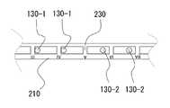
회전부(200)는, 원판상의 회전판(210)과, 상기 돌출부(130-1,2)가 돌출되었을 때 돌출부에 접촉하여 회전판(210)의 이동을 저지하며 상기 회전판(210)의 원주방향을 따라 일정 간격으로 배치된 복수의 걸림턱(230)을 포함하여 이루어진다.The
베이스판(100)에는 도 2와 같이 돌출부(120)의 구동을 제어할 수 있도록 각종 IC나 전자부품으로 이루어진 제어부(120)가 탑재되어 있으며, 제어부(120)와 돌출부(120)는 전원공급부(125)에 의해 전원을 공급받아 작동되게 된다. 전원공급부(125)는 제어부(120)의 일부이며 이하 설명되는 바와 같이 동력부(300)가 모터인 경우 동력부(300)에도 전원을 공급하게 된다.The
돌출부(130)는 도 3에 도시된 바와 같이, 돌출단부(131)와, 상기 돌출단부(131)가 회전판(210)의 걸림턱(230)에 걸릴 수 있는 위치까지 돌출단부(131)를 회전판(210)측으로 탄성지지하는 스프링(132)과, 상기 돌출단부(131)와 스프링(132)을 가이드하는 가이드부(133)와, 상기 돌출단부(131)를 회전판(210)의 걸림턱(230)에 걸리지 않는 위치까지 이동시키는 구동부(134)로 이루어져 있다.As shown in FIG. 3 , the
돌출부(130)는 돌출단부(131)를 영구자석으로, 그리고 구동부(134)를 전자석의 형태로 구비하여, 제어부에 의해 돌출부(130)의 구동을 제어할 수 있게 된다.The
돌출부(130)와 걸림턱(230)의 관계는 이후 설명하는 실시예에 한정되지 않고, 구동부(134)가 작동하지 않을 때 스프링(132)의 힘에 의해 걸림턱(230)에 걸리도록 하는 어떠한 형태의 것으로 이루어져도 상관없다.The relationship between the
또한 돌출부는 돌출단부와, 상기 돌출단부를 걸림턱에 걸리도록 하는 위치와 걸리지 않도록 하는 위치사이로 이동시키는 형상기억합금 작동부 또는 피에조 리니어 모터에 의해 이루어질 수 있다. 형상기억합금 작동부는 기억된 형상으로 복원시 걸림턱에 걸리지 않도록 하며, 복원되지 않은 형상은 자체의 탄성에 의해 늘어나는 변형에 의해 걸림턱에 걸리도록 하여 작동하게 된다.In addition, the protrusion may be made by a shape memory alloy operation unit or a piezo linear motor that moves between the protruding end and the protruding end between a position to be caught on the engaging jaw and a position not to be caught. The shape-memory alloy operation part prevents it from being caught on the locking jaw when it is restored to the memorized shape, and the unrestored shape is operated by being caught on the locking jaw by the deformation that is stretched by its elasticity.
본 발명의 동력부(300)는 감겨진 나선형 스프링에 의해 이루어지며, 나선형 스프링이 풀리면서 발생하는 회전력으로 회전판이 회전하게 된다. 동력부(300)는 모터에 의해 이루어지는 것도 가능하며, 이후 설명하는 바에 따라 일정 각도씩 회전하도록 제어 가능한 고가의 스테핑 모터 등을 사용하지 않아도 회전량의 신뢰성 있는 조절이 가능하다. 또한 동력부(300)와 회전부(200) 사이에는 기어 등에 의한 동력전달계가 설치될 수도 있음은 물론이며, 이러한 동력전달계는 동력부(300)에 포함되는 것이다.The
또한 동력부는 전기에 의해 작동하는 모터를 사용할 수도 있는데, 전기에 의해 작동하는 모터는 대한민국 등록특허 제1040474호에 개시된 회전형 초음파 모터, 또는 피에조 진동모터 및 형상기억합금에 의한 모터 등 회전력을 발생시킬 수 있는 공지의 모터 중 어떠한 것이라도 적용가능하다.In addition, the power unit may use a motor operated by electricity, and the motor operated by electricity is a rotary ultrasonic motor disclosed in Korean Patent Registration No. 1040474, or a piezo vibration motor and a motor using a shape memory alloy to generate rotational force. Any of the available known motors are applicable.
회전판(210)은 주입부(400)의 피스톤부(410)와 연결되어 있으며, 피스톤부(410)의 이동량은 회전판(210)의 회전량에 비례한다. 베이스판(110)에는 실린더부(420)가 설치되어 있으며, 실린더부(420)에는 약액(인슐린)이 저장되어 있다. 피스톤부(410)는 실린더부 내부에서 약액을 밀어주는 피스톤(410-1)과, 피스톤과 회전판 사이를 이어주는 와이어 형태의 밀대(410-2)로 이루어져 있다.(도 11 참조) 실린더(420)의 일측단부로는 피스톤부(410)가 진입하며, 다른측 단부에는 베이스판(110)을 관통하여 설치된 니들부(430)가 구비되어 있다.The
다음으로는 동력부(300)에 의해 회전하는 회전판의 회전량이 돌출부 및 걸림턱에 의해 제어되는 작동관계를 설명한다.Next, an operating relationship in which the amount of rotation of the rotating plate rotated by the
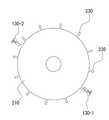
돌출부와 걸림턱의 배치는 도 6과 같이 회전판의 원주방향을 따라 배치되는 것이지만, 이해를 돕기 위하여 도 7과 같이 직선 형태로 전개하여 설명하기로 한다. 도 7 (a)~(d)는 도 6 (a)~(d)를 전개한 것이다.Although the arrangement of the protrusion and the locking protrusion is arranged along the circumferential direction of the rotating plate as shown in FIG. 6, it will be developed and described in a straight line form as shown in FIG. 7 for better understanding. 7(a)-(d) is an expanded view of FIG. 6(a)-(d).
도 7에 도시한 바와 같이 회전부(200)는 총 12개(i~xⅱ)의 걸림턱(230)을 구비하고 있다. 2 개의 돌출부(130-1.2) 중 좌측의 돌출부(130-1)은 걸림턱 iii에 걸려 있으며, 우측의 돌출부(130-2)는 걸림턱 ix와 걸림턱 x 사이에 위치하고 있다.As shown in FIG. 7 , the
회전부(200)가 동력부(300)에서 전달되는 회전력에 의해 우측으로 이동(도 1에서는 회전부(200)가 시계 반대 방향으로 회전)하려는 경우, 좌측 돌출부(130-1)가 걸림턱 iii에 걸려 이동이 불가능하다. (도 6(a), 도 7(a) 참조)When the
이때, 제어부는 돌출부(130-1)의 돌출단부(131)를 하향 이동시켜 걸림턱 iii에 걸리지 않도록 하면, 회전부(200)는 이동이 가능하게 되어 걸림턱 iii 은 돌출부(130-1) 상방으로 통과하고(도 6(b), 도 7(b) 참조), 돌출부(130-1)가 걸림턱 ii와 걸림턱 iii사이에 위치하게 된다.(도 6(c), 도 7(c) 참조) 이때, 좌측 돌출부(130-1)의 돌출단부(131)는 제어부의 제어를 받지 않고 스프링(132)의 탄성력으로 상향이동하게 된다.At this time, when the control unit moves the
계속해서 회전부(200)가 이동하다가 우측 돌출부(130-2)에 걸림턱 ix가 걸리게 되면 회전부(200)는 이동(회전)을 멈추게 된다. (도 6(d), 도 7(d) 참조)While the
이와 같은 순서로 한 단계의 이동이 완료되게 된다.In this order, the movement of one step is completed.
다음 단계에서는 우측 돌출부(130-2)의 돌출단부(131)가 하향이동시켜 걸림턱 ix가 돌출부(130-2)를 넘어서며 회전판(210)이 이동(회전)하게 되고, 좌측 돌출부(130-1)가 걸림턱 ii에 걸리게 되어 또 다른 한 단계의 이동이 발생하며, 이와 같은 방법으로 회전판의 이동이 제어되게 된다.In the next step, the
도 8에 도시한 형상과 같이, 걸림턱의 폭을 t, 걸림턱 간의 거리를 x, 돌출부의 반경을 r, 돌출부의 수를 n, 돌출부 간의 거리를 y라 하였을 때,As shown in the shape shown in Figure 8, when the width of the locking jaws is t, the distance between the locking jaws is x, the radius of the protrusions is r, the number of protrusions is n, and the distance between the protrusions is y,
y > t 이고,y > t,
걸림턱으로부터 돌출부의 중심까지의 거리 z = r + k(x+t)/n (여기서 k는 0,..., n-1이며, n은 자연수)의 위치에 걸림턱이 각각 배치되도록 이루어지게 되면, 한 단계의 이동은 (x+t)/n 만큼 변위로 이루어지게 된다.Distance z = r + k(x+t)/n (where k is 0, ..., n-1, n is a natural number) from the stopping jaw to the center of the protrusion When it loses, the movement of one step is made with a displacement by (x+t)/n.
회전판의 상기와 같은 이동에 따라 약물주입부의 피스톤은 실린더 내를 일정량만큼 이동하여 니들부로 약액이 방출되게 할 수 있는 것이다.According to the above movement of the rotating plate, the piston of the drug injection unit moves in the cylinder by a certain amount to allow the drug solution to be discharged to the needle unit.
본 실시예에서는 걸림턱에 의해 일정량의 약액이 주입되도록 하는 것을 설명하였지만, 걸림턱의 위치를 조절함에 따라 서로 다른 양의 약액을 순차적으로 주입하도록 하는 것도 가능할 것이다.In this embodiment, although it has been described that a certain amount of the chemical is injected by the locking jaw, it will be possible to sequentially inject different amounts of the chemical solution by adjusting the position of the locking jaw.
본 발명의 돌출부는 제어부에 의해 전기를 공급받는 경우에만 하방으로 이동하게 되므로, 제어가 없는 경우 스프링에 의해 상방으로 지지되어 회전부가 회전하지 못하게 억제하므로 약액의 의도치 않은 주입을 확실히 방지할 수 있게 된다.Since the protrusion of the present invention moves downward only when electricity is supplied by the control unit, if there is no control, it is supported upward by the spring to suppress the rotating part from rotating, so that unintentional injection of the chemical can be reliably prevented. do.
또한, 하나의 돌출단부를 걸림턱에서 해방시키는 순간, 동력부에 의해 회전판이 회전하며, 다른 하나의 돌출단부가 걸림턱에 걸려 회전판은 회전을 멈추게 된다. 이에 따라 일정 단위의 약액 주입에 필요한 전기는 미량으로 가능하게 되는 것이다.In addition, at the moment when one protruding end is released from the locking jaw, the rotating plate is rotated by the power unit, and the other protruding end is caught by the engaging jaw, and the rotating plate stops rotating. Accordingly, the electricity required for injecting a certain unit of the chemical is made possible in a very small amount.
돌출부는 상기 조건에 따라 2개 이상 설치될 수 있는 것이다.Two or more protrusions may be installed according to the above conditions.
또한 도 9와 같이 동일한 돌출부의 위치에 2개 이상 설치하는 것도 가능하며, 도 10과 같이 인접한 2개의 걸림턱 사이에 모든 돌출부를 설치하는 것도 가능하다.In addition, it is possible to install two or more at the same position of the protrusion as shown in FIG. 9, and it is also possible to install all the protrusions between two adjacent locking protrusions as shown in FIG.
본 실시예에서는 회전판(210)에 직각되는 위치에서 상하로 이동하는 돌출부로 설명하였으나, 도 11과 같이, 회전판(210)의 중심을 향해 돌출되도록 돌출부를 설치하는 것도 가능할 것이다. 이 경우 걸림턱은 도 1과 같이 슬릿에 의해 형성된 것이 아닌 회전판의 원주면을 따라 방사형으로 돌출된 형태로 구비되게 된다.Although the present embodiment has been described as a protrusion moving up and down at a position perpendicular to the
도 4에 도시된 주입부는 회전판(210)이 약 1/3 정도 회전하는 양만큼 변위가 발생되지만, 도 12와 같이 나선형 구조로 제작되는 경우 발생 변위를 증가시킬 수 있다.Displacement is generated in the injection unit shown in FIG. 4 by an amount by which the
도 13은 상기 회전부(200)와 주입부(400)는 일체의 모듈로 형성되어, 동력부(300)와 고정부(100)로부터 분해하거나 결합시킬 수 있는 것을 나타낸 것이다. 이에 따라 동력부와 고정부를 재활용하는 것이 가능할 뿐만 아니라, 걸림턱과 걸림턱 간의 간격을 조절하여 투입되는 용량을 변경하는 것도 가능하게 된다.13 shows that the
도 13에 도시된 바와 같이 본 발명의 약액주입장치는 회전부(200)와 주입부(400), 동력부(300)와 고정부(100)는 각각의 케이스(500,600) 내에 내장되는 형태로 사용되며, 이러한 형태에 따라 사용자의 팔뚝이나 복부 등에 벨트 또는 테이프로 부착되는 웨어러블 기기로의 사용이 가능하게 된다.13, the chemical injection device of the present invention is used in a form that the
케이스(600)에는 돌출부를 작동시키도록 제어부에 신호를 보낼 수 있는 스위치(260)가 구비되어, 사용자가 수동으로 약액의 주입을 제어부에 명령할 수도 있다.The
또한 제어부는 본 출원인의 대한민국 특허출원 10-2021-0052192호 또는 10-2021-0061323호에 개시된 혈당측정기나 그외의 알려진 혈당측정기와 연동되어 약액(인슐린)을 주입할 수 있도록 제어되는 것도 바람직하다. 이때는 당연히 외부기기와 통신이 이루어질 수 있는 통신기능이 제어부에 더 부가되어 있어야 함은 물론이다.In addition, it is preferable that the control unit be controlled to inject a drug (insulin) in conjunction with a blood glucose meter disclosed in Korean Patent Application No. 10-2021-0052192 or No. 10-2021-0061323 of the present applicant or other known blood glucose meters. In this case, of course, a communication function capable of communicating with an external device should be further added to the control unit.
100 : 베이스부 110 : 베이스판 120 : 제어부 125 : 전원공급부
130 : 돌출부 131 : 돌출단부 132 : 스프링 133 : 가이드부 134 : 구동부
200 : 회전부 210 : 회전판 230: 걸림턱 260 : 스위치 300 : 동력부
400 : 주입부 410 : 피스톤부 420 : 실린더부 430 : 니들부
500,600 : 케이스100: base 110: base plate 120: control unit 125: power supply
130: protrusion 131: protruding end 132: spring 133: guide unit 134: driving unit
200: rotating part 210: rotating plate 230: locking jaw 260: switch 300: power unit
400: injection part 410: piston part 420: cylinder part 430: needle part
500,600 : Case
Claims (16)
Translated fromKorean원판 형상의 회전판과, 상기 돌출부가 돌출되었을 때 돌출부에 접촉하여 회전판의 회전을 저지하며 상기 회전판의 원주방향을 따라 일정 간격으로 배치된 복수의 걸림턱을 구비하고, 회전가능하게 상기 베이스부에 결합되는 회전부와;
상기 베이스부와 회전부 사이에 위치하여 회전부를 회전시킬 구동력을 제공하는 동력부와;
상기 돌출부, 또는 돌출부와 동력부를 제어하는 제어부로; 이루어진 것을 특징으로 하는 구동제어기구.
a base unit having a base plate and a plurality of protrusions whose protrusions are controlled according to a control signal;
A disc-shaped rotating plate and a plurality of engaging projections arranged at regular intervals along the circumferential direction of the rotating plate to prevent rotation of the rotating plate by contacting the protruding part when the protruding part is protruded, and rotatably coupled to the base a rotating part that becomes;
a power unit positioned between the base unit and the rotating unit to provide a driving force to rotate the rotating unit;
a control unit for controlling the protrusion or the protrusion and the power unit; A drive control mechanism, characterized in that made.
상기 동력부는 탄성부재의 탄성력에 의해 구동력을 발생시키거나, 전기에 의해 작동되는 모터에 의해 구동력을 발생시키는 것을 특징으로 하는 구동제어기구.
The method of claim 1,
The power unit generates a driving force by the elastic force of the elastic member, or generates a driving force by a motor operated by electricity.
상기 회전판이 정지해 있을 때는 상기 돌출부 중 하나 이상은 상기 걸림턱과 접촉하고 있으며, 나머지는 상기 걸림턱과 이격된 상태로 유지되며,
걸림턱과 접촉된 상기 돌출부가 그 접촉이 해제되도록 이동하면 회전판이 회전하되, 걸림턱과 이격되었던 상기 돌출부가 걸림턱에 접촉되어 그 회전을 멈추도록 하는 것을 특징으로 하는 구동제어기구.
The method of claim 1,
When the rotating plate is stationary, at least one of the protrusions is in contact with the locking jaw, and the rest is maintained in a state spaced apart from the locking jaw,
The rotation plate rotates when the protrusion in contact with the locking jaw moves to release the contact, but the protrusion spaced apart from the locking jaw comes into contact with the locking jaw to stop the rotation.
상기 걸림턱의 폭을 t, 걸림턱 간의 거리를 x, 돌출부의 반경을 r, 돌출부의 수를 n, 돌출부 간의 거리를 y라 하면,
y > t 이고,
걸림턱으로부터 돌출부의 중심까지의 거리 z = r + k(x+t)/n (여기서 k는 0,..., n-1, n은 자연수)만큼 이격된 위치에 걸림턱이 각각 배치되는 것을 특징으로 하는 구동제어기구.
The method of claim 1,
If the width of the locking jaws is t, the distance between the locking jaws is x, the radius of the projections is r, the number of projections is n, and the distance between the projections is y,
y > t,
Distance z = r + k(x+t)/n (where k is 0,..., n-1, n is a natural number) A drive control mechanism, characterized in that.
상기 돌출부는 돌출단부와, 상기 돌출단부가 회전판의 걸림턱에 걸릴 수 있는 위치까지 돌출단부를 회전판측으로 탄성지지하는 스프링과, 상기 돌출단부와 스프링을 가이드하는 가이드부와, 상기 돌출단부를 회전판의 걸림턱에 걸리지 않는 위치까지 이동시키는 구동부로 이루어진 것을 특징으로 하는 구동제어기구.
The method of claim 1,
The protrusion includes a protruding end, a spring for elastically supporting the protruding end toward the rotating plate to a position where the protruding end can be caught on the locking jaw of the rotating plate, a guide portion for guiding the protruding end and the spring, and the protruding end of the rotating plate. A drive control mechanism comprising a driving unit that moves to a position where it is not caught on the locking jaw.
상기 돌출단부와 구동부는 영구자석과 전자석의 형태로 이루어지는 것을 특징으로 하는 구동제어기구.
6. The method of claim 5,
The driving control mechanism, characterized in that the protruding end and the driving part is made in the form of a permanent magnet and an electromagnet.
상기 돌출부는 돌출단부와, 상기 돌출단부를 이동시키는 형상기억합금 작동부 또는 피에조 리니어 모터에 의해 이루어지는 것을 특징으로 하는 구동제어기구.
The method of claim 1,
The protruding portion is a driving control mechanism, characterized in that made by a protruding end and a shape memory alloy operation unit or a piezo linear motor for moving the protruding end.
상기 걸림턱은 회전판에 원주방향을 따라 일정간격으로 배치된 슬릿들 사이의 부재에 의해 형성되는 것을 특징으로 하는 구동제어기구.
The method of claim 1,
The locking projection is a drive control mechanism, characterized in that formed by a member between the slits arranged at regular intervals along the circumferential direction on the rotating plate.
상기 동력부와 회전부 사이에는 기어가 설치되어 있는 것을 특징으로 하는 구동제어기구.
The method of claim 1,
A drive control mechanism, characterized in that a gear is installed between the power unit and the rotating unit.
상기 주입부는, 제어부의 돌출부 작동제어에 따른 걸림턱과 돌출부의 접촉에 의해 결정되는 회전부의 회전량만큼 이동되는 피스톤부와, 피스톤부와 결합되어 베이스판에 고정되며 내부에 약액이 저장된 실린더부와, 상기 실린더부 내부의 약액이 상기 피스톤부의 이동에 따라 방출되는 니들부를 포함한 것을 특징으로 하는 약물주입장치.
The drug injection device driven by the drive control mechanism of any one of claims 1 to 9, wherein the drug injection device has an injection unit for injecting a chemical solution according to the rotation of the rotating unit,
The injection unit includes a piston unit that is moved by the amount of rotation of the rotating unit determined by the contact between the protrusion and the protrusion according to the operation control of the protrusion of the control unit, and a cylinder unit coupled with the piston unit and fixed to the base plate and storing the chemical therein; , A drug injection device, characterized in that it comprises a needle part in which the chemical liquid inside the cylinder part is released according to the movement of the piston part.
상기 피스톤부와 실린더부는 나선형 구조로 이루어지는 것을 특징으로 하는 약물주입장치.
11. The method of claim 10,
The piston part and the cylinder part drug injection device, characterized in that made of a spiral structure.
상기 피스톤부는 실린더부 내부에서 약액을 밀어주는 피스톤과, 피스톤과 회전판 사이를 이어주는 와이어 형태의 밀대로 이루어지는 것을 특징으로 하는 약물주입장치.
11. The method of claim 10,
The piston part is a drug injection device, characterized in that consisting of a piston that pushes the chemical solution inside the cylinder, and a wire-shaped push bar connecting the piston and the rotating plate.
상기 회전부와 주입부는 일체의 모듈로 형성되어, 동력부와 고정부로부터 분해하거나 동력부와 고정부에 결합시킬 수 있는 것을 특징으로 하는 약물주입장치.
11. The method of claim 10,
The rotating unit and the injection unit are formed as an integral module, and the drug injection device, characterized in that it can be disassembled from the power unit and the fixed unit or coupled to the power unit and the fixed unit.
상기 회전부와 주입부와 동력부는 일체의 모듈로 형성되어, 고정부로부터 분해하거나 고정부에 결합시킬 수 있는 것을 특징으로 하는 약물주입장치.
11. The method of claim 10,
The rotating part, the injection part, and the power part are formed as an integral module, and the drug injection device, characterized in that it can be disassembled from the fixed part or coupled to the fixed part.
상기 제어부는 외부기기로부터의 제어신호를 수신하여 약물주입장치를 제어하는 것을 특징으로 하는 약물주입장치.
11. The method of claim 10,
The control unit receives a control signal from an external device to control the drug injection device, characterized in that the drug injection device.
상기 외부기기는 혈당측정기인 것을 특징으로 하는 약물주입장치.16. The method of claim 15,
The external device is a drug injection device, characterized in that the blood glucose meter.
Priority Applications (1)
| Application Number | Priority Date | Filing Date | Title |
|---|---|---|---|
| PCT/KR2022/002737WO2022186548A1 (en) | 2021-03-02 | 2022-02-24 | Driving control mechanism and drug injection apparatus using same |
Applications Claiming Priority (2)
| Application Number | Priority Date | Filing Date | Title |
|---|---|---|---|
| KR20210027113 | 2021-03-02 | ||
| KR1020210027113 | 2021-03-02 |
Publications (1)
| Publication Number | Publication Date |
|---|---|
| KR102336073B1true KR102336073B1 (en) | 2021-12-07 |
Family
ID=78868026
Family Applications (1)
| Application Number | Title | Priority Date | Filing Date |
|---|---|---|---|
| KR1020210077991AActiveKR102336073B1 (en) | 2021-03-02 | 2021-06-16 | Movement Control Mechanism And Infusion Device Using The Same |
Country Status (2)
| Country | Link |
|---|---|
| KR (1) | KR102336073B1 (en) |
| WO (1) | WO2022186548A1 (en) |
Cited By (1)
| Publication number | Priority date | Publication date | Assignee | Title |
|---|---|---|---|---|
| WO2022186548A1 (en)* | 2021-03-02 | 2022-09-09 | 주식회사 바리센 | Driving control mechanism and drug injection apparatus using same |
Citations (6)
| Publication number | Priority date | Publication date | Assignee | Title |
|---|---|---|---|---|
| JP2003530918A (en)* | 2000-04-13 | 2003-10-21 | ノボ ノルディスク アクティーゼルスカブ | Drug ejection device with one-way mechanism |
| US6656158B2 (en) | 2002-04-23 | 2003-12-02 | Insulet Corporation | Dispenser for patient infusion device |
| KR20060080838A (en)* | 2005-01-06 | 2006-07-11 | 김기태 | Rotary engine |
| KR20130124424A (en)* | 2012-05-04 | 2013-11-13 | 최규동 | Apparatus for supplying medicinal fluid |
| KR20160023787A (en)* | 2013-06-21 | 2016-03-03 | 아니마스 코포레이션 | Manually actuated infusion device and dose counter |
| KR101910932B1 (en) | 2016-08-31 | 2018-10-23 | 이오플로우(주) | Electoosmotic pump |
Family Cites Families (3)
| Publication number | Priority date | Publication date | Assignee | Title |
|---|---|---|---|---|
| KR101347640B1 (en)* | 2013-02-02 | 2014-01-03 | 서현배 | Cartridge-way infusion pump |
| KR20140110496A (en)* | 2013-03-08 | 2014-09-17 | 삼성전자주식회사 | Drug infusion pump |
| KR102336073B1 (en)* | 2021-03-02 | 2021-12-07 | 박철 | Movement Control Mechanism And Infusion Device Using The Same |
- 2021
- 2021-06-16KRKR1020210077991Apatent/KR102336073B1/enactiveActive
- 2022
- 2022-02-24WOPCT/KR2022/002737patent/WO2022186548A1/ennot_activeCeased
Patent Citations (6)
| Publication number | Priority date | Publication date | Assignee | Title |
|---|---|---|---|---|
| JP2003530918A (en)* | 2000-04-13 | 2003-10-21 | ノボ ノルディスク アクティーゼルスカブ | Drug ejection device with one-way mechanism |
| US6656158B2 (en) | 2002-04-23 | 2003-12-02 | Insulet Corporation | Dispenser for patient infusion device |
| KR20060080838A (en)* | 2005-01-06 | 2006-07-11 | 김기태 | Rotary engine |
| KR20130124424A (en)* | 2012-05-04 | 2013-11-13 | 최규동 | Apparatus for supplying medicinal fluid |
| KR20160023787A (en)* | 2013-06-21 | 2016-03-03 | 아니마스 코포레이션 | Manually actuated infusion device and dose counter |
| KR101910932B1 (en) | 2016-08-31 | 2018-10-23 | 이오플로우(주) | Electoosmotic pump |
Cited By (1)
| Publication number | Priority date | Publication date | Assignee | Title |
|---|---|---|---|---|
| WO2022186548A1 (en)* | 2021-03-02 | 2022-09-09 | 주식회사 바리센 | Driving control mechanism and drug injection apparatus using same |
Also Published As
| Publication number | Publication date |
|---|---|
| WO2022186548A1 (en) | 2022-09-09 |
Similar Documents
| Publication | Publication Date | Title |
|---|---|---|
| KR101928297B1 (en) | Medical fluid delivery device | |
| US4313439A (en) | Automated, spring-powered medicament infusion system | |
| ES2831604T3 (en) | Fluid Management Device and Operating Procedures | |
| JP5436653B2 (en) | Infusion medium delivery device using a drive device for driving a plunger in a storage container | |
| US10076605B2 (en) | Drug delivery device with needle actuation mechanism | |
| US8517991B2 (en) | Drive system for use with an insulin delivery device | |
| EP3970767A1 (en) | Drug infusion device | |
| JP2017094143A (en) | Long-term medical device | |
| EP4151251A1 (en) | Double-sided-driving smart control infusion device, and closed-loop artificial pancreas | |
| CN116726302A (en) | drug delivery device | |
| JP2011507555A5 (en) | ||
| WO2022116602A1 (en) | Bilaterally driven drug infusion system | |
| KR102336073B1 (en) | Movement Control Mechanism And Infusion Device Using The Same | |
| TR201807574T4 (en) | A system for medical treatment. | |
| KR20230129336A (en) | Apparatus for Infusing medical liquid | |
| Pickup et al. | Technology and the diabetic patient | |
| CN112023190B (en) | Intravenous chemotherapy device for blood internal medicine nursing | |
| KR19990070632A (en) | Drug Dosing Device for Patients with Disease | |
| KR20240043601A (en) | Needle assembly and apparatus for infusing medical liquid including the same | |
| JPH09262291A (en) | Clamp and method for blocking tube |
Legal Events
| Date | Code | Title | Description |
|---|---|---|---|
| PA0109 | Patent application | St.27 status event code:A-0-1-A10-A12-nap-PA0109 | |
| PA0201 | Request for examination | St.27 status event code:A-1-2-D10-D11-exm-PA0201 | |
| PA0302 | Request for accelerated examination | St.27 status event code:A-1-2-D10-D17-exm-PA0302 St.27 status event code:A-1-2-D10-D16-exm-PA0302 | |
| D13-X000 | Search requested | St.27 status event code:A-1-2-D10-D13-srh-X000 | |
| D14-X000 | Search report completed | St.27 status event code:A-1-2-D10-D14-srh-X000 | |
| PE0902 | Notice of grounds for rejection | St.27 status event code:A-1-2-D10-D21-exm-PE0902 | |
| P11-X000 | Amendment of application requested | St.27 status event code:A-2-2-P10-P11-nap-X000 | |
| P13-X000 | Application amended | St.27 status event code:A-2-2-P10-P13-nap-X000 | |
| PE0701 | Decision of registration | St.27 status event code:A-1-2-D10-D22-exm-PE0701 | |
| GRNT | Written decision to grant | ||
| PR0701 | Registration of establishment | St.27 status event code:A-2-4-F10-F11-exm-PR0701 | |
| PR1002 | Payment of registration fee | St.27 status event code:A-2-2-U10-U11-oth-PR1002 Fee payment year number:1 | |
| PG1601 | Publication of registration | St.27 status event code:A-4-4-Q10-Q13-nap-PG1601 | |
| PN2301 | Change of applicant | St.27 status event code:A-5-5-R10-R11-asn-PN2301 | |
| R18-X000 | Changes to party contact information recorded | St.27 status event code:A-5-5-R10-R18-oth-X000 | |
| PN2301 | Change of applicant | St.27 status event code:A-5-5-R10-R14-asn-PN2301 | |
| P14-X000 | Amendment of ip right document requested | St.27 status event code:A-5-5-P10-P14-nap-X000 | |
| R18-X000 | Changes to party contact information recorded | St.27 status event code:A-5-5-R10-R18-oth-X000 | |
| R18-X000 | Changes to party contact information recorded | St.27 status event code:A-5-5-R10-R18-oth-X000 | |
| R18-X000 | Changes to party contact information recorded | St.27 status event code:A-5-5-R10-R18-oth-X000 | |
| R18-X000 | Changes to party contact information recorded | St.27 status event code:A-5-5-R10-R18-oth-X000 |