KR102334629B1 - An apparatus for transmitting point cloud data, an apparatus for receiving point colud data - Google Patents
An apparatus for transmitting point cloud data, an apparatus for receiving point colud dataDownload PDFInfo
- Publication number
- KR102334629B1 KR102334629B1KR1020200080827AKR20200080827AKR102334629B1KR 102334629 B1KR102334629 B1KR 102334629B1KR 1020200080827 AKR1020200080827 AKR 1020200080827AKR 20200080827 AKR20200080827 AKR 20200080827AKR 102334629 B1KR102334629 B1KR 102334629B1
- Authority
- KR
- South Korea
- Prior art keywords
- point cloud
- data
- geometry
- patch
- video
- Prior art date
- Legal status (The legal status is an assumption and is not a legal conclusion. Google has not performed a legal analysis and makes no representation as to the accuracy of the status listed.)
- Active
Links
Images


Classifications
- H—ELECTRICITY
- H04—ELECTRIC COMMUNICATION TECHNIQUE
- H04N—PICTORIAL COMMUNICATION, e.g. TELEVISION
- H04N21/00—Selective content distribution, e.g. interactive television or video on demand [VOD]
- H04N21/20—Servers specifically adapted for the distribution of content, e.g. VOD servers; Operations thereof
- H04N21/23—Processing of content or additional data; Elementary server operations; Server middleware
- H04N21/236—Assembling of a multiplex stream, e.g. transport stream, by combining a video stream with other content or additional data, e.g. inserting a URL [Uniform Resource Locator] into a video stream, multiplexing software data into a video stream; Remultiplexing of multiplex streams; Insertion of stuffing bits into the multiplex stream, e.g. to obtain a constant bit-rate; Assembling of a packetised elementary stream
- H04N21/23614—Multiplexing of additional data and video streams
- H—ELECTRICITY
- H04—ELECTRIC COMMUNICATION TECHNIQUE
- H04N—PICTORIAL COMMUNICATION, e.g. TELEVISION
- H04N21/00—Selective content distribution, e.g. interactive television or video on demand [VOD]
- H04N21/80—Generation or processing of content or additional data by content creator independently of the distribution process; Content per se
- H04N21/85—Assembly of content; Generation of multimedia applications
- H04N21/854—Content authoring
- H04N21/85406—Content authoring involving a specific file format, e.g. MP4 format
- G—PHYSICS
- G06—COMPUTING OR CALCULATING; COUNTING
- G06T—IMAGE DATA PROCESSING OR GENERATION, IN GENERAL
- G06T15/00—3D [Three Dimensional] image rendering
- G06T15/04—Texture mapping
- G—PHYSICS
- G06—COMPUTING OR CALCULATING; COUNTING
- G06T—IMAGE DATA PROCESSING OR GENERATION, IN GENERAL
- G06T17/00—Three dimensional [3D] modelling, e.g. data description of 3D objects
- G06T17/05—Geographic models
- G—PHYSICS
- G06—COMPUTING OR CALCULATING; COUNTING
- G06T—IMAGE DATA PROCESSING OR GENERATION, IN GENERAL
- G06T9/00—Image coding
- G—PHYSICS
- G06—COMPUTING OR CALCULATING; COUNTING
- G06T—IMAGE DATA PROCESSING OR GENERATION, IN GENERAL
- G06T9/00—Image coding
- G06T9/001—Model-based coding, e.g. wire frame
- H—ELECTRICITY
- H04—ELECTRIC COMMUNICATION TECHNIQUE
- H04N—PICTORIAL COMMUNICATION, e.g. TELEVISION
- H04N13/00—Stereoscopic video systems; Multi-view video systems; Details thereof
- H04N13/10—Processing, recording or transmission of stereoscopic or multi-view image signals
- H04N13/106—Processing image signals
- H04N13/161—Encoding, multiplexing or demultiplexing different image signal components
- H—ELECTRICITY
- H04—ELECTRIC COMMUNICATION TECHNIQUE
- H04N—PICTORIAL COMMUNICATION, e.g. TELEVISION
- H04N13/00—Stereoscopic video systems; Multi-view video systems; Details thereof
- H04N13/10—Processing, recording or transmission of stereoscopic or multi-view image signals
- H04N13/194—Transmission of image signals
- H—ELECTRICITY
- H04—ELECTRIC COMMUNICATION TECHNIQUE
- H04N—PICTORIAL COMMUNICATION, e.g. TELEVISION
- H04N19/00—Methods or arrangements for coding, decoding, compressing or decompressing digital video signals
- H04N19/46—Embedding additional information in the video signal during the compression process
- H—ELECTRICITY
- H04—ELECTRIC COMMUNICATION TECHNIQUE
- H04N—PICTORIAL COMMUNICATION, e.g. TELEVISION
- H04N19/00—Methods or arrangements for coding, decoding, compressing or decompressing digital video signals
- H04N19/50—Methods or arrangements for coding, decoding, compressing or decompressing digital video signals using predictive coding
- H04N19/597—Methods or arrangements for coding, decoding, compressing or decompressing digital video signals using predictive coding specially adapted for multi-view video sequence encoding
- H—ELECTRICITY
- H04—ELECTRIC COMMUNICATION TECHNIQUE
- H04N—PICTORIAL COMMUNICATION, e.g. TELEVISION
- H04N21/00—Selective content distribution, e.g. interactive television or video on demand [VOD]
- H04N21/20—Servers specifically adapted for the distribution of content, e.g. VOD servers; Operations thereof
- H04N21/21—Server components or server architectures
- H04N21/218—Source of audio or video content, e.g. local disk arrays
- H04N21/21805—Source of audio or video content, e.g. local disk arrays enabling multiple viewpoints, e.g. using a plurality of cameras
- H—ELECTRICITY
- H04—ELECTRIC COMMUNICATION TECHNIQUE
- H04N—PICTORIAL COMMUNICATION, e.g. TELEVISION
- H04N21/00—Selective content distribution, e.g. interactive television or video on demand [VOD]
- H04N21/20—Servers specifically adapted for the distribution of content, e.g. VOD servers; Operations thereof
- H04N21/23—Processing of content or additional data; Elementary server operations; Server middleware
- H04N21/234—Processing of video elementary streams, e.g. splicing of video streams or manipulating encoded video stream scene graphs
- H04N21/2343—Processing of video elementary streams, e.g. splicing of video streams or manipulating encoded video stream scene graphs involving reformatting operations of video signals for distribution or compliance with end-user requests or end-user device requirements
- H—ELECTRICITY
- H04—ELECTRIC COMMUNICATION TECHNIQUE
- H04N—PICTORIAL COMMUNICATION, e.g. TELEVISION
- H04N21/00—Selective content distribution, e.g. interactive television or video on demand [VOD]
- H04N21/20—Servers specifically adapted for the distribution of content, e.g. VOD servers; Operations thereof
- H04N21/23—Processing of content or additional data; Elementary server operations; Server middleware
- H04N21/235—Processing of additional data, e.g. scrambling of additional data or processing content descriptors
- H04N21/2353—Processing of additional data, e.g. scrambling of additional data or processing content descriptors specifically adapted to content descriptors, e.g. coding, compressing or processing of metadata
- H—ELECTRICITY
- H04—ELECTRIC COMMUNICATION TECHNIQUE
- H04N—PICTORIAL COMMUNICATION, e.g. TELEVISION
- H04N21/00—Selective content distribution, e.g. interactive television or video on demand [VOD]
- H04N21/20—Servers specifically adapted for the distribution of content, e.g. VOD servers; Operations thereof
- H04N21/23—Processing of content or additional data; Elementary server operations; Server middleware
- H04N21/236—Assembling of a multiplex stream, e.g. transport stream, by combining a video stream with other content or additional data, e.g. inserting a URL [Uniform Resource Locator] into a video stream, multiplexing software data into a video stream; Remultiplexing of multiplex streams; Insertion of stuffing bits into the multiplex stream, e.g. to obtain a constant bit-rate; Assembling of a packetised elementary stream
- H04N21/23605—Creation or processing of packetized elementary streams [PES]
- H—ELECTRICITY
- H04—ELECTRIC COMMUNICATION TECHNIQUE
- H04N—PICTORIAL COMMUNICATION, e.g. TELEVISION
- H04N21/00—Selective content distribution, e.g. interactive television or video on demand [VOD]
- H04N21/40—Client devices specifically adapted for the reception of or interaction with content, e.g. set-top-box [STB]; Operations thereof
- H04N21/43—Processing of content or additional data, e.g. demultiplexing additional data from a digital video stream; Elementary client operations, e.g. monitoring of home network or synchronising decoder's clock; Client middleware
- H04N21/434—Disassembling of a multiplex stream, e.g. demultiplexing audio and video streams, extraction of additional data from a video stream; Remultiplexing of multiplex streams; Extraction or processing of SI; Disassembling of packetised elementary stream
- H04N21/4343—Extraction or processing of packetized elementary streams [PES]
- H—ELECTRICITY
- H04—ELECTRIC COMMUNICATION TECHNIQUE
- H04N—PICTORIAL COMMUNICATION, e.g. TELEVISION
- H04N21/00—Selective content distribution, e.g. interactive television or video on demand [VOD]
- H04N21/40—Client devices specifically adapted for the reception of or interaction with content, e.g. set-top-box [STB]; Operations thereof
- H04N21/43—Processing of content or additional data, e.g. demultiplexing additional data from a digital video stream; Elementary client operations, e.g. monitoring of home network or synchronising decoder's clock; Client middleware
- H04N21/434—Disassembling of a multiplex stream, e.g. demultiplexing audio and video streams, extraction of additional data from a video stream; Remultiplexing of multiplex streams; Extraction or processing of SI; Disassembling of packetised elementary stream
- H04N21/4348—Demultiplexing of additional data and video streams
- H—ELECTRICITY
- H04—ELECTRIC COMMUNICATION TECHNIQUE
- H04N—PICTORIAL COMMUNICATION, e.g. TELEVISION
- H04N21/00—Selective content distribution, e.g. interactive television or video on demand [VOD]
- H04N21/40—Client devices specifically adapted for the reception of or interaction with content, e.g. set-top-box [STB]; Operations thereof
- H04N21/43—Processing of content or additional data, e.g. demultiplexing additional data from a digital video stream; Elementary client operations, e.g. monitoring of home network or synchronising decoder's clock; Client middleware
- H04N21/44—Processing of video elementary streams, e.g. splicing a video clip retrieved from local storage with an incoming video stream or rendering scenes according to encoded video stream scene graphs
- H04N21/4402—Processing of video elementary streams, e.g. splicing a video clip retrieved from local storage with an incoming video stream or rendering scenes according to encoded video stream scene graphs involving reformatting operations of video signals for household redistribution, storage or real-time display
- H—ELECTRICITY
- H04—ELECTRIC COMMUNICATION TECHNIQUE
- H04N—PICTORIAL COMMUNICATION, e.g. TELEVISION
- H04N21/00—Selective content distribution, e.g. interactive television or video on demand [VOD]
- H04N21/80—Generation or processing of content or additional data by content creator independently of the distribution process; Content per se
- H04N21/81—Monomedia components thereof
- H04N21/816—Monomedia components thereof involving special video data, e.g 3D video
- G—PHYSICS
- G06—COMPUTING OR CALCULATING; COUNTING
- G06T—IMAGE DATA PROCESSING OR GENERATION, IN GENERAL
- G06T2207/00—Indexing scheme for image analysis or image enhancement
- G06T2207/10—Image acquisition modality
- G06T2207/10028—Range image; Depth image; 3D point clouds
- H—ELECTRICITY
- H04—ELECTRIC COMMUNICATION TECHNIQUE
- H04N—PICTORIAL COMMUNICATION, e.g. TELEVISION
- H04N19/00—Methods or arrangements for coding, decoding, compressing or decompressing digital video signals
- H04N19/70—Methods or arrangements for coding, decoding, compressing or decompressing digital video signals characterised by syntax aspects related to video coding, e.g. related to compression standards
Landscapes
- Engineering & Computer Science (AREA)
- Multimedia (AREA)
- Signal Processing (AREA)
- Physics & Mathematics (AREA)
- Theoretical Computer Science (AREA)
- General Physics & Mathematics (AREA)
- Computer Graphics (AREA)
- Geometry (AREA)
- Software Systems (AREA)
- Library & Information Science (AREA)
- Remote Sensing (AREA)
- Databases & Information Systems (AREA)
- Computer Security & Cryptography (AREA)
- Compression Or Coding Systems Of Tv Signals (AREA)
Abstract
Translated fromKoreanDescription
Translated fromKorean실시예들은 사용자에게 VR (Virtual Reality, 가상현실), AR (Augmented Reality, 증강현실), MR (Mixed Reality, 혼합현실), 및 자율 주행 서비스 등의 다양한 서비스를 제공하기 위하여 Point Cloud 콘텐츠를 제공하는 방안을 제공한다.Embodiments provide Point Cloud content to provide users with various services such as VR (Virtual Reality), AR (Augmented Reality, Augmented Reality), MR (Mixed Reality), and autonomous driving service. provide a way
포인트 클라우드는 3D공간 상의 포인트들의 집합이다. 3D공간 상의 포인트들의 양이 많아서 포인트 클라우드 데이터를 생성하기 어려운 문제점이 있다.A point cloud is a set of points in 3D space. There is a problem in that it is difficult to generate point cloud data because the amount of points in 3D space is large.
포인트 클라우드의 데이터를 전송하고 수신하기 위해서 많은 처리량이 요구되는 문제점이 있다.There is a problem in that a large amount of processing is required to transmit and receive data of the point cloud.
실시예들에 따른 기술적 과제는, 전술한 문제점 등을 해결하기 위해서, 포인트 클라우드를 효율적으로 송수신하기 위한 포인트 클라우드 데이터 전송 장치, 전송 방법, 포인트 클라우드 데이터 수신 장치 및 수신 방법을 제공하는데 있다.SUMMARY An object of the present invention is to provide a point cloud data transmission apparatus, a transmission method, a point cloud data reception apparatus, and a reception method for efficiently transmitting and receiving a point cloud in order to solve the above-described problems.
실시예들에 따른 기술적 과제는, 지연시간(latency) 및 인코딩/디코딩 복잡도를 해결하기 위한 포인트 클라우드 데이터 전송 장치, 전송 방법, 포인트 클라우드 데이터 수신 장치 및 수신 방법을 제공하는데 있다.An object of the present invention is to provide a point cloud data transmission apparatus, a transmission method, a point cloud data reception apparatus, and a reception method for solving latency and encoding/decoding complexity.
다만, 전술한 기술적 과제만으로 제한되는 것은 아니고, 본 문서 전체 내용에 기초하여 당업자가 유추할 수 있는 다른 기술적 과제로 실시예들의 권리범위가 확장될 수 있다.However, it is not limited only to the above-described technical problems, and the scope of rights of the embodiments may be extended to other technical problems that can be inferred by those skilled in the art based on the entire contents of this document.
상술한 목적 및 다른 이점을 달성하기 위해서 실시예들에 따른 포인트 클라우드 데이터 송신 방법은 포인트 클라우드 데이터를 인코딩하는 단계; 및/또는 인코딩된 포인트 클라우드 데이터 및 포인트 클라우드 데이터에 대한 메타데이터를 포함하는 비트스트림을 전송하는 단계; 를 포함할 수 있다.In order to achieve the above object and other advantages, a method for transmitting point cloud data according to embodiments includes encoding point cloud data; and/or transmitting a bitstream including the encoded point cloud data and metadata for the point cloud data; may include
나아가 실시예들에 따르면, 인코딩된 포인트 클라우드 데이터는 지오메트리(geometry) 데이터 및 어트리뷰트 데이터(attribute data)를 포함할 수 있다.Further, according to embodiments, the encoded point cloud data may include geometry data and attribute data.
나아가, 실시예들에 따른 인코딩된 포인트 클라우드 데이터는 지오메트리 데이터 및 어트리뷰트 데이터를 전달(carry)하는 하나 또는 그 이상의 샘플(sample)들을 포함할 수 있고, 인코딩하는 단계는 특정 인코딩 방식에 기초하여 수행될 수 있다.Furthermore, the encoded point cloud data according to embodiments may include one or more samples carrying geometry data and attribute data, and the encoding may be performed based on a specific encoding method. can
실시예들에 따른 상기 메타데이터는 샘플 내의 지오메트리 데이터 또는 어트리뷰트 데이터가 상기 특정 인코딩 방식에만 기초하여 인코딩되었는지 여부를 나타내는 정보를 더 포함할 수 있다.The metadata according to embodiments may further include information indicating whether geometry data or attribute data in a sample is encoded based only on the specific encoding method.
더 나아가, 실시예들에 따르면, 특정 방식에 따라 인코딩된 지오메트리 데이터 및 어트리뷰트 데이터는 하나의 샘플 내에 포함되거나, 특정 방식에 따라 인코딩된 지오메트리 데이터 및 어트리뷰트 데이터는 서로 다른 샘플들 내에 포함될 수 있다.Furthermore, according to embodiments, geometry data and attribute data encoded according to a specific scheme may be included in one sample, or geometry data and attribute data encoded according to a specific scheme may be included in different samples.
실시예들에 따르면, 특정 인코딩 방식은 PCM(Pulse Coding Modulation) 방식일 수 있다.According to embodiments, a specific encoding method may be a pulse coding modulation (PCM) method.
실시예들에 따르면, 메타데이터는 트랙(track)과 트랙에 대응하는 포인트 클라우드 데이터를 참조하기 위한 트랙 레퍼런스 타입 박스(TrackReferenceTypeBox)를 포함할 수 있고, 트랙 레퍼런스 타입 박스는 트랙에 대응하는 포인트 클라우드 데이터의 타입을 나타내는 레퍼런스 타입(reference type) 정보를 포함할 수 있다.According to embodiments, the metadata may include a track reference type box (TrackReferenceTypeBox) for referencing a track and point cloud data corresponding to the track, wherein the track reference type box is point cloud data corresponding to the track. may include reference type information indicating the type of .
실시예들에 따르면, 레퍼런스 타입 정보는 트랙에 대응하는 포인트 클라우드 데이터가 특정 방식에 기초하여 인코딩되는지 여부를 더 나타낼 수 있다.According to embodiments, the reference type information may further indicate whether the point cloud data corresponding to the track is encoded based on a specific scheme.
실시예들에 따른 포인트 클라우드 데이터 수신 방법은 포인트 클라우드 데이터 및 메타데이터를 포함하는 비트스트림을 수신하는 단계; 및/또는 포인트 클라우드 데이터를 디코딩하는 단계; 를 포함할 수 있다.A method of receiving point cloud data according to embodiments may include: receiving a bitstream including point cloud data and metadata; and/or decoding the point cloud data; may include
나아가, 실시예들에 따르면, 포인트 클라우드 데이터는 지오메트리(geometry) 데이터 및 어트리뷰트(attribute) 데이터를 전달(carry)하는 하나 또는 그 이상의 샘플(sample)들을 포함할 수 있다. 또한, 지오메트리 데이터 및 어트리뷰트 데이터는 특정 방식에 따라 인코딩된 데이터일 수 있고, 특정 인코딩 방식은 예를 들어 PCM(Pulse Coding Modulation) 방식일 수 있다.Furthermore, according to embodiments, the point cloud data may include one or more samples carrying geometry data and attribute data. Also, the geometry data and the attribute data may be data encoded according to a specific method, and the specific encoding method may be, for example, a pulse coding modulation (PCM) method.
실시예들에 따른 메타데이터는 샘플을 구성하는 지오메트리 또는 어트리뷰트 데이터가 특정 인코딩 방식에 기초하여 인코딩되는지 여부를 나타내는 정보를 더 포함할 수 있다.Metadata according to embodiments may further include information indicating whether geometry or attribute data constituting a sample is encoded based on a specific encoding method.
실시예들에 따른 포인트 클라우드 데이터 송신 방법, 송신 장치, 포인트 클라우드 데이터 수신 방법, 수신 장치는 퀄리티 있는 포인트 클라우드 서비스를 제공할 수 있다.The point cloud data transmission method, the transmission device, the point cloud data reception method, and the reception device according to the embodiments may provide a quality point cloud service.
실시예들에 따른 포인트 클라우드 데이터 송신 방법, 송신 장치, 포인트 클라우드 데이터 수신 방법, 수신 장치는 다양한 비디오 코덱 방식을 달성할 수 있다.The point cloud data transmission method, the transmission device, the point cloud data reception method, and the reception device according to the embodiments may achieve various video codec schemes.
실시예들에 따른 포인트 클라우드 데이터 송신 방법, 송신 장치, 포인트 클라우드 데이터 수신 방법, 수신 장치는 자율주행 서비스 등 범용적인 포인트 클라우드 콘텐츠를 제공할 수 있다.The point cloud data transmission method, the transmission device, the point cloud data reception method, and the reception device according to the embodiments may provide universal point cloud content such as an autonomous driving service.
실시예들에 따른 포인트 클라우드 데이터 송신 방법, 송신 장치는 포인트 클라우드 데이터가 인코딩되는 과정에서 유실된 포인트들의 데이터(지오메트리 데이터, 어트리뷰트 데이터 및/또는 어큐펀시 데이터)를 효율적으로 인코딩할 수 있다.A method and a transmission apparatus for transmitting point cloud data according to embodiments may efficiently encode data (geometric data, attribute data, and/or accumulating data) of points lost in a process of encoding the point cloud data.
실시예들에 따른 포인트 클라우드 데이터 수신 방법, 수신 장치는 포인트 클라우드 데이터가 인코딩되는 과정에서 유실된 포인트들의 데이터(지오메트리 데이터, 어트리뷰트 데이터 및/또는 어큐펀시 데이터)를 효율적으로 수신 및 복원할 수 있다.The point cloud data receiving method and receiving apparatus according to the embodiments may efficiently receive and restore data (geometric data, attribute data, and/or accuracy data) of points lost in the process of encoding the point cloud data. .
실시예들에 따른 포인트 클라우드 데이터 송신 방법, 송신 장치는 특정 방식(예를 들어, PCM 방식 등)에 의해 인코딩된 포인트 클라우드 데이터를 단일 트랙(track)으로 전달할지 또는 복수의 트랙으로 전달할지 여부를 시그널링함으로써, 수신기의 성능에 따라 적응적으로 디코딩을 수행할 수 있게 한다.Point cloud data transmission method according to the embodiments, the transmission device transmits the point cloud data encoded by a specific method (eg, PCM method, etc.) as a single track or whether to transmit it as a plurality of tracks By signaling, decoding can be adaptively performed according to the performance of the receiver.
실시예들에 따른 포인트 클라우드 데이터 수신 방법, 수신 장치는 특정 방식(예를 들어, PCM 방식 등)에 의해 인코딩된 포인트 클라우드 데이터가 단일 트랙(track)으로 전달되는지 또는 복수의 트랙으로 전달되는지 여부를 나타내는 정보에 기초하여 디코딩함으로써, 수신기의 성능에 따라 적응적으로 디코딩을 수행할 수 있다.A method for receiving point cloud data according to embodiments, a receiving device determines whether point cloud data encoded by a specific method (eg, PCM method, etc.) is transmitted as a single track or a plurality of tracks By decoding based on the indicated information, decoding can be adaptively performed according to the performance of the receiver.
도면은 실시예들을 더욱 이해하기 위해서 포함되며, 도면은 실시예들에 관련된 설명과 함께 실시예들을 나타낸다.
도1은 실시예들에 따른 Point Cloud 콘텐츠 제공을 위한 송신/수신 시스템의 구조의 예시를 나타낸다.
도2는 실시예들에 따른 포인트 클라우드 데이터 갭쳐의 예시를 나타낸다.
도3은 실시예들에 따른 포인트 클라우드 및 지오메트리, 텍스쳐 이미지의 예시를 나타낸다.
도4는 실시예들에 따른 V-PCC 인코딩 처리의 예시를 나타낸다.
도5는 실시예들에 따른 서페이스(Surface)의 탄젠트 플렌(tangent plane) 및 노멀 벡터(normal vector)의 예시를 나타낸다.
도6은 실시예들에 따른 포인트 클라우드의 바운딩 박스(bounding box)의 예시를 나타낸다.
도7은 실시예들에 따른 어큐판시 맵(occupancy map)의 개별 패치(patch) 위치 결정의 예시를 나타낸다.
도8은 실시예들에 따른 노멀(normal), 탄젠트(tangent), 바이탄젠트(bitangent) 축의 관계의 예시를 나타낸다.
도9는 실시예들에 따른 프로젝션 모드의 최소 모드 및 최대 모드의 구성의 예시를 나타낸다.
도10은 실시예들에 따른 EDD 코드의 예시를 나타낸다.
도11은 실시예들에 따른 인접점들의 컬러(color) 값들을 이용한 리컬러링(recoloring)의 예시를 나타낸다.
도12는 실시예들에 따른 푸쉬-풀 백그라운드 필링(push-pull background filling)의 예시를 나타낸다.
도13은 실시예들에 따른 4*4 크기의 블록(block)에 대해 가능한 트라버설 오더(traversal order)의 예시를 나타낸다.
도14는 실시예들에 따른 베스트 트라버설 오더의 예시를 나타낸다.
도15는 실시예들에 따른 2D 비디오/이미지 인코더(2D video/image Encoder)의 예시를 나타낸다.
도16은 실시예들에 따른 V-PCC 디코딩 프로세스(decoding process)의 예시를 나타낸다.
도17은 실시예들에 따른 2D 비디오/이미지 디코더(2D Video/Image Decoder)의 예시를 나타낸다.
도18은 실시예들에 따른 송신 장치의 동작 흐름도의 예시를 나타낸다.
도19는 실시예들에 따른 수신 장치의 동작 흐름도의 예시를 나타낸다.
도20은 실시예들에 따른 V-PCC 기반 포인트 클라우드 데이터 저장 및 스트리밍을 위한 아키텍쳐의 예시를 나타낸다.
도21은 실시예들에 따른 포인트 클라우드 데이터 저장 및 전송 장치의 구성도의 예시를 나타낸다.
도22는 실시예들에 따른 포인트 클라우드 데이터 수신 장치의 구성도의 예시를 나타낸다.
도23은 실시예들에 따른 포인트 클라우드 데이터 송수신 방법/장치와 연동 가능한 구조의 예시를 나타낸다.
도 24은 실시예들에 따른 ISOBMFF 파일의 포멧(format)의 포인트 클라우드 데이터를 나타낸다.
도 25은 실시예들에 따른 ISOBMFF 파일의 포멧(format)의 포인트 클라우드 데이터의 구조의 예시를 나타낸다.
도 26은 실시예들에 따른 ISOBMFF 파일 포멧의 포인트 클라우드 데이터를 나타낸다.
도 27은 실시예들에 따른 포인트 클라우드 데이터가 전송되는 V-PCC 유닛을 나타낸다.
도 28은 실시예들에 따른 V-PCC 유닛(V-PCC Unit)에 포함된 데이터를 나타낸다.
도 29는 실시예들에 따른 PCM 데이터가 전송되는 방법의 예시를 나타낸다.
도 30은 실시예들에 따른 포인트 클라우드 데이터가 PCM 데이터를 전송하는 방법의 다른 예시를 나타낸다.
도 31은 실시예들에 따른 VPCC 유닛 헤더(V-PCC unit header)의 신텍스(syntax)를 나타낸다.
도 32은 실시예들에 따른 VPCC 유닛 페이로드(V-PCC unit payload)의 신텍스(syntax)를 나타낸다.
도 33은 실시예들에 따른 시퀀스 파라미터 세트(Sequence Parameter Set) 데이터의 신텍스(syntax)를 나타낸다.
도 34은 실시예들에 따른 패치 데이터 그룹(Patch Data Group, PDG)의 신텍스(syntax)를 나타낸다.
도 35는 실시예들에 따른 패치 시퀀스 파라미터 세트(Patch Sequence Parameter Set)의 신텍스(syntax)를 나타낸다.
도 36 은 실시예들에 따른 패치 프레임 지오메트리 파라미터 세트(Patch Frame Geometry Parameter Set)를 나타낸다.
도 37 은 실시예들에 따른 패치 프레임 어트리뷰트 파라미터 세트(Patch Frame Attribute Parameter Set)를 나타낸다.
도 38은 실시예들에 따른 지오메트리 패치 파라미터 세트(Geometry Patch Parameter Set)를 나타낸다.
도 39는 실시예들에 따른 어트리뷰트 패치 파라미터 세트(Attribute Patch Parameter Set)를 나타낸다.
도 40은 실시예들에 따른 패치 프레임 파라미터 세트(Patch Frame Parameter Set)를 나타낸다.
도 41은 실시예들에 따른 패치 타일 그룹 레이어 유닛(Patch Tile Group Layer Unit)에 포함된 패치 타일 그룹 헤더(patch tile group header)를 나타낸다.
도 42는 실시예들에 따른 레퍼런스 리스트 스트럭처(Reference List Structure)를 나타낸다.
도 43은 실시예들에 따른 패치 타일 그룹 데이터 유닛(Patch Tile Group Data Unit)를 나타낸다.
도 44는 실시예들에 따른 패치 타일 그룹 데이터 유닛(Patch Tile Group Data Unit) 내의 패치 데이터 유닛(patch data unit)를 나타낸다.
도 45는 실시예들에 따른 패치 타일 그룹 데이터 유닛(Patch Tile Group Data Unit) 내의 패치 데이터 유닛(patch data unit)를 나타낸다.
도 46은 실시예들에 따른 SEI 메시지(SEI message, Supplemental enhancement information message)를 나타낸다.
도 47은 실시예들에 따른 포인트 로컬 리컨스트럭션 데이터(Point Local Reconstruction Data)를 나타낸다.
도 48은 실시예들에 따른 포인트 클라우드 데이터를 전송하는 방법을 나타낸 흐름도이다.
도 49은 실시예들에 따른 포인트 클라우드 데이터를 수신하는 방법을 나타낸 흐름도이다.BRIEF DESCRIPTION OF THE DRAWINGS The drawings are included to further understand the embodiments, and the drawings, together with a description related to the embodiments, represent the embodiments.
1 shows an example of the structure of a transmission/reception system for providing Point Cloud content according to embodiments.
2 shows an example of a point cloud data capturer according to embodiments.
3 shows an example of a point cloud, a geometry, and a texture image according to embodiments.
4 shows an example of V-PCC encoding processing according to the embodiments.
5 shows an example of a tangent plane and a normal vector of a surface according to embodiments.
6 shows an example of a bounding box of a point cloud according to embodiments.
7 shows an example of individual patch location determination of an occupancy map according to embodiments.
8 shows an example of a relationship between normal, tangent, and bitangent axes according to embodiments.
9 shows an example of the configuration of the minimum mode and the maximum mode of the projection mode according to the embodiments.
10 shows an example of an EDD code according to embodiments.
11 shows an example of recoloring using color values of adjacent points according to embodiments.
12 shows an example of push-pull background filling according to embodiments.
13 shows an example of a possible traversal order for a block of 4*4 size according to embodiments.
14 shows an example of a best traversal order according to embodiments.
15 shows an example of a 2D video/image encoder according to embodiments.
16 shows an example of a V-PCC decoding process according to embodiments.
17 shows an example of a 2D video/image decoder according to embodiments.
18 shows an example of an operation flowchart of a transmitting apparatus according to the embodiments.
19 shows an example of an operation flowchart of a receiving apparatus according to the embodiments.
20 shows an example of an architecture for V-PCC-based point cloud data storage and streaming according to embodiments.
21 shows an example of a configuration diagram of an apparatus for storing and transmitting point cloud data according to embodiments.
22 shows an example of a configuration diagram of an apparatus for receiving point cloud data according to embodiments.
23 shows an example of a structure capable of interworking with a method/device for transmitting and receiving point cloud data according to embodiments.
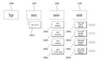
24 shows point cloud data in a format of an ISOBMFF file according to embodiments.
25 shows an example of a structure of point cloud data in a format of an ISOBMFF file according to embodiments.
26 shows point cloud data in an ISOBMFF file format according to embodiments.
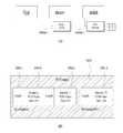
27 illustrates a V-PCC unit to which point cloud data is transmitted according to embodiments.
28 illustrates data included in a V-PCC unit according to embodiments.
29 shows an example of a method in which PCM data is transmitted according to embodiments.
30 illustrates another example of a method for point cloud data to transmit PCM data according to embodiments.
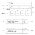
31 shows a syntax of a VPCC unit header (V-PCC unit header) according to embodiments.
32 shows a syntax of a VPCC unit payload (V-PCC unit payload) according to embodiments.
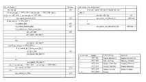
33 illustrates a syntax of sequence parameter set data according to embodiments.
34 illustrates a syntax of a Patch Data Group (PDG) according to embodiments.
35 illustrates a syntax of a patch sequence parameter set according to embodiments.
36 illustrates a Patch Frame Geometry Parameter Set according to embodiments.
37 illustrates a Patch Frame Attribute Parameter Set according to embodiments.
38 illustrates a geometry patch parameter set according to example embodiments.
39 shows an attribute patch parameter set according to embodiments.
40 illustrates a Patch Frame Parameter Set according to embodiments.
41 illustrates a patch tile group header included in a patch tile group layer unit according to embodiments.
42 shows a reference list structure according to embodiments.
43 illustrates a Patch Tile Group Data Unit according to embodiments.
44 illustrates a patch data unit in a Patch Tile Group Data Unit according to embodiments.
45 illustrates a patch data unit in a patch tile group data unit according to embodiments.
46 illustrates an SEI message (Supplemental enhancement information message) according to embodiments.
47 illustrates Point Local Reconstruction Data according to embodiments.
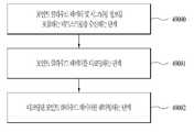
48 is a flowchart illustrating a method of transmitting point cloud data according to embodiments.
49 is a flowchart illustrating a method of receiving point cloud data according to embodiments.
실시예들의 바람직한 실시예에 대해 구체적으로 설명하며, 그 예는 첨부된 도면에 나타낸다. 첨부된 도면을 참조한 아래의 상세한 설명은 실시예들의 실시예에 따라 구현될 수 있는 실시예만을 나타내기보다는 실시예들의 바람직한 실시예를 설명하기 위한 것이다. 다음의 상세한 설명은 실시예들에 대한 철저한 이해를 제공하기 위해 세부 사항을 포함한다. 그러나 실시예들이 이러한 세부 사항 없이 실행될 수 있다는 것은 당업자에게 자명하다.Preferred embodiments of the embodiments will be specifically described, examples of which are shown in the accompanying drawings. DETAILED DESCRIPTION OF THE PREFERRED EMBODIMENTS The detailed description below with reference to the accompanying drawings is intended to describe preferred embodiments of the embodiments rather than only showing embodiments that may be implemented according to the embodiments of the embodiments. The following detailed description includes details to provide a thorough understanding of the embodiments. However, it will be apparent to one skilled in the art that the embodiments may be practiced without these details.
실시예들에서 사용되는 대부분의 용어는 해당 분야에서 널리 사용되는 일반적인 것들에서 선택되지만, 일부 용어는 출원인에 의해 임의로 선택되며 그 의미는 필요에 따라 다음 설명에서 자세히 서술한다. 따라서 실시예들은 용어의 단순한 명칭이나 의미가 아닌 용어의 의도된 의미에 근거하여 이해되어야 한다.Most terms used in the embodiments are selected from general ones widely used in the relevant field, but some terms are arbitrarily selected by the applicant and their meanings will be described in detail in the following description as necessary. Therefore, the embodiments should be understood based on the intended meaning of the term rather than the simple name or meaning of the term.
도1은 실시예들에 따른 Point Cloud 콘텐츠 제공을 위한 송신/수신 시스템의 구조의 예시를 나타낸다.1 shows an example of the structure of a transmission/reception system for providing Point Cloud content according to embodiments.
본 문서에서는 사용자에게 VR (Virtual Reality, 가상현실), AR (Augmented Reality, 증강현실), MR (Mixed Reality, 혼합현실), 및 자율 주행 서비스 등의 다양한 서비스를 제공하기 위하여 Point Cloud 콘텐츠를 제공하는 방안을 제공한다. 실시예들에 다른 포인트 클라우드 콘텐츠는 오브젝트를 포인트들로 표현한 데이터를 나타내고, 포인트 클라우드, 포인트 클라우드 데이터, 포인트 클라우드 비디오 데이터, 포인트 클라우드 이미지 데이터 등으로 지칭될 수 있다.In this document, to provide users with various services such as VR (Virtual Reality), AR (Augmented Reality), MR (Mixed Reality), and autonomous driving service, point cloud content is provided. provide a way Point cloud content according to embodiments may represent data representing an object as points, and may be referred to as point cloud, point cloud data, point cloud video data, point cloud image data, and the like.
실시예들에 따른 포인트 클라우드 데이터 전송 장치(Transmission device, 10000)는 포인트 클라우드 비디오 획득부(Point Cloud Video Acquisition, 10001), 포인트 클라우드 비디오 인코더(Point Cloud Video Encoder, 10002), 파일/세그먼트 인캡슐레이션부(10003) 및/또는 트랜스미터(Transmitter (or Communication module), 10004)를 포함한다. 실시예들에 따른 전송 장치는 포인트 클라우드 비디오(또는 포인트 클라우드 콘텐트)를 확보하고 처리하여 전송할 수 있다. 실시예들에 따라, 전송 장치는 고정국(fixed station), BTS(base transceiver system), 네트워크, AI(Ariticial Intelligence) 기기 및/또는 시스템, 로봇, AR/VR/XR 기기 및/또는 서버 등을 포함할 수 있다. 또한 실시예들에 따라 전송 장치(10000)는 무선 접속 기술(예, 5G NR(New RAT), LTE(Long Term Evolution))을 이용하여, 기지국 및/또는 다른 무선 기기와 통신을 수행하는 기기, 로봇, 차량, AR/VR/XR 기기, 휴대기기, 가전, IoT(Internet of Thing)기기, AI 기기/서버 등을 포함할 수 있다.A point cloud data transmission device (Transmission device, 10000) according to embodiments includes a point cloud video acquisition unit (Point Cloud Video Acquisition, 10001), a point cloud video encoder (Point Cloud Video Encoder, 10002), and file/segment encapsulation. a
실시예들에 따른 포인트 클라우드 비디오 획득부(Point Cloud Video Acquisition, 10001)는 Point Cloud 비디오의 캡처, 합성 또는 생성 과정 등을 통한 Point Cloud 비디오를 획득한다.A point cloud video acquisition unit (Point Cloud Video Acquisition, 10001) according to embodiments acquires a Point Cloud video through a process of capturing, synthesizing, or generating a Point Cloud video.
실시예들에 따른 포인트 클라우드 비디오 인코더(Point Cloud Video Encoder, 10002)는 포인트 클라우드 비디오 데이터를 인코딩한다. 실시예들에 따라, 포인트 클라우드 비디오 인코더(10002)는 포인트 클라우드 인코더, 포인트 클라우드 데이터 인코더, 인코더 등으로 지칭될 수 있다. 또한 실시예들에 따른 포인트 클라우드 컴프레션 코딩(인코딩)은 상술한 실시예에 국한되는 것은 아니다. 포인트 클라우드 비디오 인코더는 인코딩된 포인트 클라우드 비디오 데이터를 포함하는 비트스트림을 출력할 수 있다. 비트스트림은 인코딩된 포인트 클라우드 비디오 데이터뿐만 아니라, 포인트 클라우드 비디오 데이터의 인코딩과 관련된 시그널링 정보를 포함할 수 있다.A Point
실시예들에 따른 인코더는 G-PCC (Geometry-based Point Cloud Compression) 인코딩 방식 및/또는 V-PCC(Video-based Point Cloud Compression) 인코딩 방식을 모두 지원할 수 있다. 또한, 인코더는 포인트 클라우드 (포인트 클라우드 데이터 또는 포인트들을 모두 지칭함) 및/또는 포인트 클라우드에 관한 시그널링 데이터를 인코딩할 수 있다. 실시예들에 따른 인코딩의 구체적인 동작은 이하에서 설명한다.The encoder according to the embodiments may support both a Geometry-based Point Cloud Compression (G-PCC) encoding method and/or a Video-based Point Cloud Compression (V-PCC) encoding method. In addition, the encoder may encode a point cloud (referring to point cloud data or both points) and/or signaling data related to the point cloud. Specific operations of encoding according to embodiments will be described below.
한편, 본 문서에서 사용하는 V-PCC 용어는 비디오 기반 포인트 클라우드 압축(Video-based Point Cloud Compression (V-PCC))을 의미하고, V-PCC 용어는 비쥬얼 볼륨메트릭 비디오 기반 코딩(Visual Volumetric Video-based Coding (V3C))과 동일하고, 서로 상호 보완하여 지칭될 수 있다.Meanwhile, the term V-PCC used in this document refers to Video-based Point Cloud Compression (V-PCC), and the term V-PCC refers to Visual Volumetric Video- based Coding (V3C)) and may be referred to as complementary to each other.
실시예들에 따른 파일/세그먼트 인캡슐레이션부(File/Segment Encapsulation module, 10003)은 포인트 클라우드 데이터를 파일 및/또는 세그먼트 형태로 인캡슐레이션한다. 실시예들에 따른 포인트 클라우드 데이터 송신 방법/장치는 포인트 클라우드 데이터를 파일 및/또는 세그먼트 형태로 전송할 수 있다.The file/
실시예들에 따른 트랜스미터(Transmitter (or Communication module), 10004)는 인코딩된 포인트 클라우드 비디오 데이터를 비트스트림의 형태로 전송한다. 실시예들에 따라 파일 또는 세그먼트는 네트워크를 통해 수신 장치로 전송되거나, 디지털 저장매체(예를 들면 USB, SD, CD, DVD, 블루레이, HDD, SSD 등)에 저장될 수 있다. 실시예들에 따른 트랜스미터는 수신 장치 (또는 리시버(Receiver)와 4G, 5G, 6G 등의 네트워크를 통해 유/무선 통신 가능하다. 또한 트랜스미터는 네트워크 시스템(예를 들면 4G, 5G, 6G 등의 통신 네트워크 시스템)에 따라 필요한 데이터 처리 동작을 수행할 수 있다. 또한 전송 장치는 온 디맨드(On Demand) 방식에 따라 인캡슐레이션된 데이터를 전송할 수도 있다.A transmitter (or Communication module) 10004 according to embodiments transmits encoded point cloud video data in the form of a bitstream. According to embodiments, the file or segment may be transmitted to a receiving device through a network or stored in a digital storage medium (eg, USB, SD, CD, DVD, Blu-ray, HDD, SSD, etc.). The transmitter according to the embodiments may communicate with a receiving device (or a receiver) through wired/wireless communication through a network such as 4G, 5G, 6G, etc. In addition, the transmitter may communicate with a network system (eg, 4G, 5G, 6G, etc.) a data processing operation required according to the network system) In addition, the transmission device may transmit encapsulated data according to an on demand method.
실시예들에 따른 포인트 클라우드 데이터 수신 장치(Reception device, 10005)는 리시버(Receiver, 10006), 파일/세그먼트 디캡슐레이션부(10007), 포인트 클라우드 비디오 디코더(Point Cloud Decoder, 10008), 및/또는 렌더러(Renderer, 10009)를 포함한다. 실시예들에 따라 수신 장치는 무선 접속 기술(예, 5G NR(New RAT), LTE(Long Term Evolution))을 이용하여, 기지국 및/또는 다른 무선 기기와 통신을 수행하는 기기, 로봇, 차량, AR/VR/XR 기기, 휴대기기, 가전, IoT(Internet of Thing)기기, AI 기기/서버 등을 포함할 수 있다.Point cloud data receiving device (Reception device, 10005) according to embodiments is a receiver (Receiver, 10006), a file / segment decapsulation unit (10007), a point cloud video decoder (Point Cloud Decoder, 10008), and / or Contains the renderer (Renderer, 10009). According to embodiments, the receiving device uses a radio access technology (eg, 5G NR (New RAT), LTE (Long Term Evolution)) to communicate with a base station and/or other wireless device, a device, a robot, a vehicle, AR/VR/XR devices, mobile devices, home appliances, Internet of Things (IoT) devices, AI devices/servers, etc. may be included.
실시예들에 따른 리시버(Receiver, 10006)는 포인트 클라우드 비디오 데이터를 포함하는 비트스트림을 수신한다. 실시예들에 따라 리시버(10006)는 피드백 정보(Feedback Information)을 포인트 클라우드 데이터 전송 장치(10000)에 전송할 수 있다.A
파일/세그먼트 디캡슐레이션부(File/Segment Decapsulation module, 10007)은 포인트 클라우드 데이터를 포함하는 파일 및/또는 세그먼트를 디캡슐레이션한다. 실시예들에 따른 디캡슐레이션부는 실시예들에 따른 인캡슐레이션 과정의 역과정을 수행할 수 있다.The file/
포인트 클라우드 비디오 디코더(Point Cloud Decoder, 10007)는 수신된 포인트 클라우드 비디오 데이터를 디코딩한다. 실시예들에 따른 디코더는 실시예들에 따른 인코딩의 역과정을 수행할 수 있다.The point cloud video decoder (Point Cloud Decoder, 10007) decodes the received point cloud video data. The decoder according to the embodiments may perform the reverse process of encoding according to the embodiments.
렌더러(Renderer, 10007)는 디코딩된 포인트 클라우드 비디오 데이터를 렌더링한다. 실시예들에 따라 렌더러(10007)는 수신단 측에서 획득된 피드백 정보를 포인트 클라우드 비디오 디코더(10006)에 전송할 수 있다. 실시예들에 따른 포인트 클라우드 비디오 데이터는 피드백 정보를 리시버에 전송할 수 있다. 실시예들에 따라 포인트 클라우드 전송 장치가 수신한 피드백 정보는 포인트 클라우드 비디오 인코더에 제공될 수 있다.A renderer (Renderer, 10007) renders the decoded point cloud video data. According to embodiments, the
도면에 점선으로 표시된 화살표는 수신 장치(10005)에서 획득한 피드백 정보(feedback information)의 전송 경로를 나타낸다. 피드백 정보는 포인트 클라우드 컨텐트를 소비하는 사용자와의 인터랙티비를 반영하기 위한 정보로서, 사용자의 정보(예를 들면 헤드 오리엔테이션 정보), 뷰포트(Viewport) 정보 등)을 포함한다. 특히 포인트 클라우드 콘텐트가 사용자와의 상호작용이 필요한 서비스(예를 들면 자율주행 서비스 등)를 위한 콘텐트인 경우, 피드백 정보는 콘텐트 송신측(예를 들면 전송 장치(10000)) 및/또는 서비스 프로바이더에게 전달될 수 있다. 실시예들에 따라 피드백 정보는 전송 장치(10000) 뿐만 아니라 수신 장치(10005)에서도 사용될 수 있으며, 제공되지 않을 수도 있다.An arrow indicated by a dotted line in the drawing indicates a transmission path of the feedback information obtained by the receiving
실시예들에 따른 헤드 오리엔테이션 정보는 사용자의 머리 위치, 방향, 각도, 움직임 등에 대한 정보이다. 실시예들에 따른 수신 장치(10005)는 헤드 오리엔테이션 정보를 기반으로 뷰포트 정보를 계산할 수 있다. 뷰포트 정보는 사용자가 바라보고 있는 포인트 클라우드 비디오의 영역에 대한 정보이다. 시점(viewpoint)은 사용자가 포인트 클라우 비디오를 보고 있는 점으로 뷰포트 영역의 정중앙 지점을 의미할 수 있다. 즉, 뷰포트는 시점을 중심으로 한 영역으로서, 영역의 크기, 형태 등은 FOV(Field Of View) 에 의해 결정될 수 있다. 따라서 수신 장치(10004)는 헤드 오리엔테이션 정보 외에 장치가 지원하는 수직(vertical) 혹은 수평(horizontal) FOV 등을 기반으로 뷰포트 정보를 추출할 수 있다. 또한 수신 장치(10005)는 게이즈 분석 (Gaze Analysis) 등을 수행하여 사용자의 포인트 클라우드 소비 방식, 사용자가 응시하는 포인트 클라우 비디오 영역, 응시 시간 등을 확인한다. 실시예들에 따라 수신 장치(10005)는 게이즈 분석 결과를 포함하는 피드백 정보를 송신 장치(10000)로 전송할 수 있다. 실시예들에 따른 피드백 정보는 렌더링 및/또는 디스플레이 과정에서 획득될 수 있다. 실시예들에 따른 피드백 정보는 수신 장치(10005)에 포함된 하나 또는 그 이상의 센서들에 의해 확보될 수 있다. 또한 실시예들에 따라 피드백 정보는 렌더러(10009) 또는 별도의 외부 엘레멘트(또는 디바이스, 컴포넌트 등)에 의해 확보될 수 있다. 도1의 점선은 렌더러(10009)에서 확보한 피드백 정보의 전달 과정을 나타낸다. 포인트 클라우드 콘텐트 제공 시스템은 피드백 정보를 기반으로 포인트 클라우드 데이터를 처리(인코딩/디코딩)할 수 있다. 따라서 포인트 클라우드 비디오 데이터 디코더(10008)는 피드백 정보를 기반으로 디코딩 동작을 수행할 수 있다. 또한 수신 장치(10005)는 피드백 정보를 전송 장치로 전송할 수 있다. 전송 장치(또는 포인트 클라우드 비디오 데이터 인코더(10002))는 피드백 정보를 기반으로 인코딩 동작을 수행할 수 있다. 따라서 포인트 클라우드 콘텐트 제공 시스템은 모든 포인트 클라우드 데이터를 처리(인코딩/디코딩)하지 않고, 피드백 정보를 기반으로 필요한 데이터(예를 들면 사용자의 헤드 위치에 대응하는 포인트 클라우드 데이터)를 효율적으로 처리하고, 사용자에게 포인트 클라우드 콘텐트를 제공할 수 있다.The head orientation information according to the embodiments is information about the user's head position, direction, angle, movement, and the like. The
실시예들에 따라, 전송 장치(10000)는 인코더, 전송 디바이스, 전송기 등으로 호칭될 수 있으며, 수신 장치(10004)는 디코더, 수신 디바이스, 수신기 등으로 호칭될 수 있다.According to embodiments, the transmitting
실시예들에 따른 도 1 의 포인트 클라우드 콘텐트 제공 시스템에서 처리되는 (획득/인코딩/전송/디코딩/렌더링의 일련의 과정으로 처리되는) 포인트 클라우드 데이터는 포인트 클라우드 콘텐트 데이터 또는 포인트 클라우드 비디오 데이터라고 호칭할 수 있다. 실시예들에 따라 포인트 클라우드 콘텐트 데이터는 포인트 클라우드 데이터와 관련된 메타데이터 내지 시그널링 정보를 포함하는 개념으로 사용될 수 있다.Point cloud data (processed in a series of acquisition/encoding/transmission/decoding/rendering) processed in the point cloud content providing system of FIG. 1 according to embodiments may be referred to as point cloud content data or point cloud video data. can According to embodiments, the point cloud content data may be used as a concept including metadata or signaling information related to the point cloud data.
도 1에 도시된 포인트 클라우드 콘텐트 제공 시스템의 엘리먼트들은 하드웨어, 소프트웨어, 프로세서 및/또는 그것들의 결합등으로 구현될 수 있다.The elements of the point cloud content providing system shown in FIG. 1 may be implemented by hardware, software, a processor and/or a combination thereof.
실시예들은 사용자에게 VR (Virtual Reality, 가상현실), AR (Augmented Reality, 증강현실), MR (Mixed Reality, 혼합현실), 및 자율 주행 서비스 등 다양한 서비스를 제공하기 위하여 포인트 클라우드(Point Cloud) 콘텐츠를 제공할 수 있다.The embodiments provide a user with various services such as VR (Virtual Reality), AR (Augmented Reality), MR (Mixed Reality), and autonomous driving service. Point Cloud content can provide
Point Cloud 콘텐츠 서비스를 제공하기 위하여, 먼저 Point Cloud 비디오가 획득될 수 있다. 획득된 Point Cloud 비디오는 일련의 과정을 거쳐 전송되고, 수신측에서는 수신된 데이터를 다시 원래의 Point Cloud 비디오로 가공하여 렌더링 할 수 있다. 이를 통해 Point Cloud 비디오가 사용자에게 제공될 수 있다. 실시예들은 이러한 일련의 과정을 효과적으로 수행하기 위해 필요한 방안을 제공한다.In order to provide a Point Cloud content service, a Point Cloud video may be acquired first. The acquired Point Cloud video is transmitted through a series of processes, and the receiving end can process the received data back into the original Point Cloud video and render it. This allows Point Cloud video to be presented to users. The embodiments provide methods necessary for effectively performing such a series of processes.
Point Cloud 콘텐츠 서비스를 제공하기 위한 전체의 과정(포인트 클라우드 데이터 전송 방법 및/또는 포인트 클라우드 데이터 수신 방법)은 획득 과정, 인코딩 과정, 전송 과정, 디코딩 과정, 렌더링 과정 및/또는 피드백 과정을 포함할 수 있다.The whole process (point cloud data transmission method and/or point cloud data reception method) for providing the Point Cloud content service may include an acquisition process, an encoding process, a transmission process, a decoding process, a rendering process, and/or a feedback process. have.
실시예들에 따라 포인트 클라우드 콘텐츠 (또는 포인트 클라우드 데이터)를 제공하는 과정은 포인트 클라우드 컴프레션(Point Cloud Compression) 과정이라고 호칭할 수 있다. 실시예들에 따라 포인트 클라우드 컴프레션 과정은 지오메트리 기반 포인트 클라우드 컴프레션(Geometry-based Point Cloud Compression) 과정을 의미할 수 있다.According to embodiments, a process of providing point cloud content (or point cloud data) may be referred to as a point cloud compression process. According to embodiments, the point cloud compression process may refer to a geometry-based point cloud compression process.
실시예들에 따른 포인트 클라우드 데이터 전송 장치 및 포인트 클라우드 데이터 수신 장치의 각 엘리먼트는 하드웨어, 소프트웨어, 프로세서 및/또는 그것들의 결합 등을 의미할 수 있다.Each element of the point cloud data transmitting apparatus and the point cloud data receiving apparatus according to the embodiments may mean hardware, software, a processor, and/or a combination thereof.
Point Cloud 콘텐츠 서비스를 제공하기 위하여, 먼저 Point Cloud 비디오가 획득될 수 있다. 획득된 Point Cloud 비디오는 일련의 과정을 거쳐 전송되고, 수신측에서는 수신된 데이터를 다시 원래의 Point Cloud 비디오로 가공하여 렌더링 할 수 있다. 이를 통해 Point Cloud 비디오가 사용자에게 제공될 수 있다. 본 발명은 이러한 일련의 과정을 효과적으로 수행하기 위해 필요한 방안을 제공한다.In order to provide a Point Cloud content service, a Point Cloud video may be acquired first. The acquired Point Cloud video is transmitted through a series of processes, and the receiving end can process the received data back into the original Point Cloud video and render it. This allows Point Cloud video to be presented to users. The present invention provides a method necessary for effectively performing such a series of processes.
Point Cloud 콘텐츠 서비스를 제공하기 위한 전체의 과정은 획득 과정, 인코딩 과정, 전송 과정, 디코딩 과정, 렌더링 과정 및/또는 피드백 과정을 포함할 수 있다.The whole process for providing the Point Cloud content service may include an acquisition process, an encoding process, a transmission process, a decoding process, a rendering process, and/or a feedback process.
Point Cloud Compression 시스템은 전송 디바이스 및 수신 디바이스를 포함할 수 있다. 전송 디바이스는 Point Cloud 비디오를 인코딩하여 비트스트림을 출력할 수 있으며, 이를 파일 또는 스트리밍 (스트리밍 세그먼트) 형태로 디지털 저장매체 또는 네트워크를 통하여 수신 디바이스로 전달할 수 있다. 디지털 저장 매체는 USB, SD, CD, DVD, 블루레이, HDD, SSD 등 다양한 저장 매체를 포함할 수 있다.The Point Cloud Compression system may include a transmitting device and a receiving device. The transmitting device can output the bitstream by encoding the Point Cloud video, and it can be delivered to the receiving device in the form of a file or streaming (streaming segment) through a digital storage medium or network. The digital storage medium may include a variety of storage media such as USB, SD, CD, DVD, Blu-ray, HDD, and SSD.
전송 디바이스는 개략적으로 Point Cloud 비디오 획득부, Point Cloud 비디오 인코더, 파일/세그먼트 인캡슐레이션부, 전송부를 포함할 수 있다. 수신 디바이스는 개략적으로 수신부, 파일/세그먼트 디캡슐레이션부, Point Cloud 비디오 디코더 및 렌더러를 포함할 수 있다. 인코더는 Point Cloud 비디오/영상/픽처/프레임 인코딩 장치라고 불릴 수 있고, 디코더는 Point Cloud 비디오/영상/픽처/프레임 디코딩 장치라고 불릴 수 있다. 송신기는 Point Cloud 비디오 인코더에 포함될 수 있다. 수신기는 Point Cloud 비디오 디코더에 포함될 수 있다. 렌더러는 디스플레이부를 포함할 수도 있고, 렌더러 및/또는 디스플레이부는 별개의 디바이스 또는 외부 컴포넌트로 구성될 수도 있다. 전송 디바이스 및 수신 디바이스는 피드백 과정을 위한 별도의 내부 또는 외부의 모듈/유닛/컴포넌트를 더 포함할 수도 있다.The transmission device may schematically include a Point Cloud video acquisition unit, a Point Cloud video encoder, a file/segment encapsulation unit, and a transmission unit. The receiving device may schematically include a receiving unit, a file/segment decapsulation unit, a Point Cloud video decoder, and a renderer. The encoder may be called a Point Cloud video/video/picture/frame encoding device, and the decoder may be called a Point Cloud video/video/picture/frame decoding device. The transmitter may be included in the Point Cloud video encoder. The receiver may be included in the Point Cloud video decoder. The renderer may include a display unit, and the renderer and/or the display unit may be configured as a separate device or external component. The transmitting device and the receiving device may further include separate internal or external modules/units/components for the feedback process.
실시예들에 따라 수신 디바이스의 동작은 전송 디바이스 동작의 역과정을 따를 수 있다.According to embodiments, the operation of the receiving device may follow a reverse process of the operation of the transmitting device.
Point Cloud 비디오 획득부는 Point Cloud 비디오의 캡처, 합성 또는 생성 과정 등을 통한 Point Cloud 비디오를 획득하는 과정을 수행할 수 있다. 획득 과정에 의해 다수의 Point들에 대한 3D 위치(x, y, z)/속성 (color, reflectance, transparency 등) 데이터, 예를 들어, PLY(Polygon File format or the Stanford Triangle format) 파일 등이 생성 될 수 있다. 여러 개의 프레임을 갖는 비디오의 경우 하나 이상의 파일들이 획득될 수 있다. 캡처 과정에서 point cloud 관련 메타데이터(예를 들어 캡처와 관련된 메타데이터 등)가 생성될 수 있다.The Point Cloud video acquisition unit may perform the process of acquiring Point Cloud video through capturing, synthesizing, or generating Point Cloud video. 3D position (x, y, z)/property (color, reflectance, transparency, etc.) data for a plurality of Points are generated by the acquisition process, for example, PLY (Polygon File format or the Stanford Triangle format) file can be For video with multiple frames, one or more files may be acquired. During the capture process, metadata related to the point cloud (eg, metadata related to capture, etc.) may be generated.
실시예들에 따른 포인트 클라우드 데이터 송신 장치는 포인트 클라우드 데이터를 인코딩하는 인코더; 및 포인트 클라우드 데이터를 전송하는 트랜스미터; 를 포함할 수 있다. 또한, 포인트 클라우드를 포함하는 비트 스트림의 형태로 전송될 수 있다.An apparatus for transmitting point cloud data according to embodiments includes an encoder for encoding point cloud data; and a transmitter for transmitting point cloud data; may include In addition, it may be transmitted in the form of a bit stream including a point cloud.
실시예들에 따른 포인트 클라우드 데이터 수신 장치는 포인트 클라우드 데이터를 수신하는 수신부; 포인트 클라우드 데이터를 디코딩하는 디코더; 및 포인트 클라우드 데이터를 렌더링하는 렌더러; 를 포함할 수 있다.An apparatus for receiving point cloud data according to embodiments includes a receiver configured to receive point cloud data; a decoder for decoding point cloud data; and a renderer that renders the point cloud data; may include
실시예들에 따른 방법/장치는 포인트 클라우드 데이터 송신 장치 및/또는 포인트 클라우드 데이터 수신 장치를 나타낸다.A method/apparatus according to the embodiments represents an apparatus for transmitting point cloud data and/or an apparatus for receiving point cloud data.
도2는 실시예들에 따른 포인트 클라우드 데이터 갭쳐의 예시를 나타낸다.2 shows an example of a point cloud data capturer according to embodiments.
실시예들에 따른 포인트 클라우드 데이터는 카메라 등에 의해 획득될 수 있다. 실시예들에 따른 캡쳐 방법은 예를 들어 인워드-페이싱 및/또는 아웃워드-페이싱이 있을 수 있다.Point cloud data according to embodiments may be acquired by a camera or the like. A capture method according to embodiments may include, for example, inward-pacing and/or outward-pacing.
실시예들에 따른 인워드-페이싱은 포인트 클라우드 데이터의 오브젝트(Object)를 하나 또는 하나 이상의 카메라들이 오브젝트의 바깥에서 안쪽 방향으로 촬영할 수 있다.Inward-facing according to embodiments, one or more cameras may photograph an object of point cloud data from the outside to the inside.
실시예들에 따른 아웃워드-페이싱은 포인트 클라우드 데이터의 오브젝트를 하나 또는 하나 이상의 카메라들이 오브젝트의 안쪽에서 바깥 방향으로 촬영할 수 있다. 예를 들어, 실시예들에 따라 카메라는 4개일 수 있다.In the outward-pacing according to embodiments, one or more cameras may photograph the object of the point cloud data from the inside to the outside. For example, according to embodiments, there may be four cameras.
실시예들에 따른 포인트 클라우드 데이터 또는 포인트 클라우드 콘텐츠는 다양한 형태의 3D 공간상에 표현되는 객체/환경의 비디오 또는 정지 영상일 수 있다. 실시예들에 따라, 포인트 클라우드 콘텐츠는 객체(오브젝트 등)에 대한 비디오/오디오/이미지 등을 포함할 수 있다.Point cloud data or point cloud content according to embodiments may be a video or still image of an object/environment expressed in various types of 3D space. According to embodiments, the point cloud content may include video/audio/images for an object (object, etc.).
Point Cloud 콘텐츠 캡쳐를 위해서 깊이(depth)를 획득 할 수 있는 카메라 장비(적외선 패턴 프로젝터와 적외선 카메라의 조합)와 깊이 정보에 대응되는 색상 정보를 추출 할 수 있는 RGB 카메라들의 조합으로 구성될 수 있다. 또는 레이저 펄스를 쏘고 반사되어 돌아오는 시간을 측정하여 반사체의 위치 좌표를 측정하는 레이더 시스템을 이용하는 라이다(LiDAR)를 통해 깊이 정보를 추출할 수 있다. 깊이 정보로부터 3차원 공간상의 점들로 구성된 지오메트리(geometry)의 형태를 추출하고, RGB 정보로부터 각 점의 색상/반사를 표현하는 속성(attribute)을 추출할 수 있다. Point Cloud 콘텐츠는 점들에 대한 위치(x, y, z)와 색상(YCbCr 또는 RGB) 또는 반사율(r) 정보로 구성될 수 있다. Point Cloud 콘텐츠는 외부 환경을 캡쳐하는 아웃워드-페이싱(outward-facing) 방식과, 중심 객체를 캡쳐하는 인워드-페이싱(inward-facing) 방식이 있을 수 있다. VR/AR 환경에서 객체(예-캐릭터, 선수, 물건, 배우 등 핵심이 되는 객체)를 360도로 사용자가 자유롭게 볼 수 있는 Point Cloud 콘텐츠로 구성할 경우, 캡쳐 카메라의 구성은 인워드-페이싱 방식을 사용하게 될 수 있다. 자율 주행과 같이 자동차에서 현재 주변 환경을 Point Cloud 콘텐츠로 구성할 경우, 캡쳐 카메라의 구성은 아웃워드-페이싱 방식을 사용하게 될 수 있다. 여러대의 카메라를 통해 Point Cloud 콘텐츠가 캡쳐 될 수 있기 때문에, 카메라들 사이의 글로벌 공간 좌표계(global coordinate system)를 설정하기 위해 콘텐츠를 캡쳐 하기 전에 카메라의 캘리브레이션 과정이 필요할 수도 있다.For point cloud content capture, it can be composed of a combination of camera equipment that can acquire depth (a combination of an infrared pattern projector and an infrared camera) and RGB cameras that can extract color information corresponding to depth information. Alternatively, depth information can be extracted through LiDAR using a radar system that measures the position coordinates of a reflector by emitting a laser pulse and measuring the time it takes to reflect and return. It is possible to extract the shape of a geometry composed of points in a three-dimensional space from the depth information, and extract an attribute representing the color/reflection of each point from the RGB information. Point Cloud contents may consist of position (x, y, z) and color (YCbCr or RGB) or reflectance (r) information for points. Point Cloud content may have an outward-facing method for capturing the external environment and an inward-facing method for capturing a central object. In a VR/AR environment, if an object (e.g., a core object such as a character, player, object, actor, etc.) is composed of Point Cloud content that users can freely view in 360 degrees, the configuration of the capture camera is based on the inward-facing method. can be used When configuring the current surrounding environment in a car as point cloud content, such as in autonomous driving, the configuration of the capture camera may use an outward-facing method. Since Point Cloud content can be captured through multiple cameras, it may be necessary to calibrate the camera before capturing the content to set the global coordinate system between the cameras.
Point Cloud 콘텐츠는 다양한 형태의 3D 공간상에 나타내어지는 객체/환경의 비디오 또는 정지 영상일 수 있다.The Point Cloud content may be a video or still image of an object/environment displayed on various types of 3D space.
그 외에 Point Cloud 콘텐츠의 획득 방법은 캡쳐 된 Point Cloud 비디오를 기반으로 임의의 Point Cloud 비디오가 합성 될 수 있다. 또는 컴퓨터로 생성된 가상의 공간에 대한 Point Cloud 비디오를 제공하고자 하는 경우, 실제 카메라를 통한 캡처가 수행되지 않을 수 있다. 이 경우 단순히 관련 데이터가 생성되는 과정으로 해당 캡처 과정이 갈음될 수 있다.In addition, as for the method of acquiring Point Cloud content, arbitrary Point Cloud video can be synthesized based on the captured Point Cloud video. Alternatively, if you want to provide Point Cloud video for a computer-generated virtual space, capture through a real camera may not be performed. In this case, the process of simply generating related data may be substituted for the process of capturing.
캡쳐된 Point Cloud 비디오는 콘텐츠의 질을 향상시키기 위한 후처리가 필요할 수 있다. 영상 캡쳐 과정에서 카메라 장비가 제공하는 범위에서 최대/최소 깊이 값을 조정할 수 있지만 그 이후에도 원하지 않는 영역의 points 데이터들이 포함될 수 있어서 원하지 않는 영역(예, 배경)을 제거 한다거나, 또는 연결된 공간을 인식하고 구멍(spatial hole)을 메우는 후처리를 수행할 수 있다. 또한 공간 좌표계를 공유하는 카메라들로부터 추출된 Point Cloud는 캘리브레이션 과정을 통해 획득된 각 카메라의 위치 좌표를 기준으로 각 point들에 대한 글로벌 좌표계로의 변환 과정을 통해 하나의 콘텐츠로 통합될 수 있다. 이를 통해 하나의 넓은 범위의 Point Cloud 콘텐츠를 생성할 수도 있고, 또는 point들의 밀도가 높은 Point Cloud 콘텐츠를 획득할 수도 있다.Captured Point Cloud video may require post-processing to improve the quality of the content. During the video capture process, you can adjust the maximum/minimum depth values within the range provided by the camera equipment, but even after that, points data of an unwanted area may be included, so it removes an unwanted area (eg, background), or recognizes a connected space. Post-treatment to fill the spatial hole may be performed. In addition, the Point Cloud extracted from the cameras sharing the spatial coordinate system can be integrated into one content through the conversion process to the global coordinate system for each point based on the position coordinates of each camera obtained through the calibration process. Through this, one wide range of Point Cloud contents can be created, or Point Cloud contents with a high density of points can be obtained.
Point Cloud 비디오 인코더는 입력 Point Cloud 비디오를 하나 이상의 비디오 스트림으로 인코딩할 수 있다. 하나의 비디오는 다수의 프레임을 포함할 수 있으며, 하나의 프레임은 정지 영상/픽처에 대응될 수 있다. 본 문서에서, Point Cloud 비디오라 함은 Point Cloud 영상/프레임/픽처/비디오/오디오/이미지 등을 포함할 수 있으며, Point Cloud 비디오는 Point Cloud 영상/프레임/픽처와 혼용되어 사용될 수 있다. Point Cloud 비디오 인코더는 Video-based Point Cloud Compression (V-PCC) 절차를 수행할 수 있다. Point Cloud 비디오 인코더는 압축 및 코딩 효율을 위하여 예측, 변환, 양자화, 엔트로피 코딩 등의 일련의 절차를 수행할 수 있다. 인코딩된 데이터(인코딩된 비디오/영상 정보)는 비트스트림(bitstream) 형태로 출력될 수 있다. V-PCC 절차에 기반하는 경우 Point Cloud 비디오 인코더는 Point Cloud 비디오를 후술하는 바와 같이 지오메트리 비디오, 어트리뷰트(attribute) 비디오, 어큐판시(occupancy) 맵 비디오, 그리고 부가 정보(auxiliary information)으로 나누어 인코딩할 수 있다. 지오메트리 비디오는 지오메트리 이미지를 포함할 수 있고, 어트리뷰트(attribute) 비디오는 어트리뷰트 이미지를 포함할 수 있고, 어큐판시(occupancy) 맵 비디오는 어큐판시 맵 이미지를 포함할 수 있다. 부가 정보는 부가 패치 정보(auxiliary patch information)를 포함할 수 있다. 어트리뷰트 비디오/이미지는 텍스쳐 비디오/이미지를 포함할 수 있다.A Point Cloud video encoder can encode an input Point Cloud video into one or more video streams. One video may include a plurality of frames, and one frame may correspond to a still image/picture. In this document, Point Cloud video may include Point Cloud video/frame/picture/video/audio/image, etc., and Point Cloud video may be used in combination with Point Cloud video/frame/picture. The Point Cloud video encoder may perform a Video-based Point Cloud Compression (V-PCC) procedure. The Point Cloud video encoder can perform a series of procedures such as prediction, transformation, quantization, and entropy coding for compression and coding efficiency. The encoded data (encoded video/image information) may be output in the form of a bitstream. When based on the V-PCC procedure, the Point Cloud video encoder divides the Point Cloud video into geometry video, attribute video, occupancy map video, and auxiliary information, as described below. have. A geometry video may include a geometry image, an attribute video may include an attribute image, and an occupancy map video may include an occupancy map image. The additional information may include auxiliary patch information. The attribute video/image may include a texture video/image.
인캡슐레이션 처리부(file/segment encapsulation module, 10003)는 인코딩된 Point cloud 비디오 데이터 및/또는 Point cloud 비디오 관련 메타데이터를 파일 등의 형태로 인캡슐레이션할 수 있다. 여기서 Point cloud 비디오 관련 메타데이터는 메타데이터 처리부 등으로부터 전달받은 것일 수 있다. 메타데이터 처리부는 point cloud 비디오 인코더에 포함될 수도 있고, 또는 별도의 컴포넌트/모듈로 구성될 수도 있다. 인캡슐레이션 처리부는 해당 데이터들을 ISOBMFF 등의 파일 포맷으로 인캡슐레이션하거나, 기타 DASH 세그먼트 등의 형태로 처리할 수 있다. 인캡슐레이션 처리부는 실시예에 따라 Point cloud 비디오 관련 메타데이터를 파일 포맷 상에 포함시킬 수 있다. Point cloud 비디오 메타데이터는 예를 들어 ISOBMFF 파일 포맷 상의 다양한 레벨의 박스(box)에 포함되거나 파일 내에서 별도의 트랙내의 데이터로 포함될 수 있다. 실시예에 따라, 인캡슐레이션 처리부는 Point cloud 비디오 관련 메타데이터 자체를 파일로 인캡슐레이션할 수 있다. 전송 처리부는 파일 포맷에 따라 인캡슐레이션된 Point cloud 비디오 데이터에 전송을 위한 처리를 가할 수 있다. 전송 처리부는 전송부에 포함될 수도 있고, 또는 별도의 컴포넌트/모듈로 구성될 수도 있다. 전송 처리부는 임의의 전송 프로토콜에 따라 Point cloud 비디오비디오 데이터를 처리할 수 있다. 전송을 위한 처리에는 방송망을 통한 전달을 위한 처리, 브로드밴드를 통한 전달을 위한 처리를 포함할 수 있다. 실시예에 따라 전송 처리부는 Point cloud 비디오 데이터 뿐 아니라, 메타데이터 처리부로부터 Point cloud 비디오관련 메타데이터를 전달받아, 이 것에 전송을 위한 처리를 가할 수도 있다.The encapsulation processing unit (file/segment encapsulation module, 10003) may encapsulate the encoded Point cloud video data and/or Point cloud video related metadata in the form of a file or the like. Here, the point cloud video-related metadata may be delivered from a metadata processing unit, etc. The metadata processing unit may be included in the point cloud video encoder, or may be configured as a separate component/module. The encapsulation processing unit may encapsulate the data in a file format such as ISOBMFF or process the data in the form of other DASH segments. The encapsulation processing unit may include point cloud video related metadata in a file format according to an embodiment. Point cloud video metadata may be included, for example, in boxes of various levels in the ISOBMFF file format, or as data in separate tracks within the file. According to an embodiment, the encapsulation processing unit may encapsulate the point cloud video-related metadata itself into a file. The transmission processing unit may apply processing for transmission to the encapsulated Point cloud video data according to the file format. The transmission processing unit may be included in the transmission unit, or may be configured as a separate component/module. The transmission processing unit can process the point cloud video video data according to any transmission protocol. The processing for transmission may include processing for transmission through a broadcasting network and processing for transmission through a broadband. According to an embodiment, the transmission processing unit may receive not only the point cloud video data but also the point cloud video-related metadata from the metadata processing unit, and may apply processing for transmission thereto.
전송부(10004)는 비트스트림 형태로 출력된 인코딩된 비디오/영상 정보 또는 데이터를 파일 또는 스트리밍 형태로 디지털 저장매체 또는 네트워크를 통하여 수신 디바이스의 수신부로 전달할 수 있다. 디지털 저장 매체는 USB, SD, CD, DVD, 블루레이, HDD, SSD 등 다양한 저장 매체를 포함할 수 있다. 전송부는 미리 정해진 파일 포멧을 통하여 미디어 파일을 생성하기 위한 엘리먼트를 포함할 수 있고, 방송/통신 네트워크를 통한 전송을 위한 엘레멘트를 포함할 수 있다. 수신부는 비트스트림을 추출하여 디코딩 장치로 전달할 수 있다.The transmitting
수신부(10003)는 본 발명에 따른 point cloud 비디오 전송 장치가 전송한 point cloud 비디오 데이터를 수신할 수 있다. 전송되는 채널에 따라 수신부는 방송망을 통하여 point cloud 비디오 데이터를 수신할 수도 있고, 브로드밴드를 통하여 point cloud 비디오 데이터를 수신할 수도 있다. 혹은 디지털 저장 매체를 통하여 point cloud 비디오 데이터를 수신할 수도 있다.The
수신 처리부는 수신된 point cloud 비디오 데이터에 대해 전송 프로토콜에 따른 처리를 수행할 수 있다. 수신 처리부는 수신부에 포함될 수 있고, 또는 별도의 컴포넌트/모듈로 구성될 수도 있다. 전송측에서 전송을 위한 처리가 수행된 것에 대응되도록, 수신 처리부는 전술한 전송 처리부의 역과정을 수행할 수 있다. 수신 처리부는 획득한 point cloud 비디오 데이터는 디캡슐레이션 처리부로 전달하고, 획득한 point cloud 비디오 관련 메타데이터는 메타데이터 파서로 전달할 수 있다. 수신 처리부가 획득하는 point cloud 비디오 관련 메타데이터는 시그널링 테이블의 형태일 수 있다.The reception processing unit may perform processing according to the transmission protocol on the received point cloud video data. The reception processing unit may be included in the reception unit, or may be configured as a separate component/module. The reception processing unit may perform the reverse process of the above-described transmission processing unit so that the transmission side corresponds to the processing performed for transmission. The reception processing unit may transmit the acquired point cloud video data to the decapsulation processing unit, and the acquired point cloud video related metadata may be transmitted to the metadata parser. The point cloud video-related metadata acquired by the reception processing unit may be in the form of a signaling table.
디캡슐레이션 처리부(file/segment decapsulation module, 10007)는 수신 처리부로부터 전달받은 파일 형태의 point cloud 비디오 데이터를 디캡슐레이션할 수 있다. 디캡슐레이션 처리부는 ISOBMFF 등에 따른 파일들을 디캡슐레이션하여, point cloud 비디오 비트스트림 내지 point cloud 비디오 관련 메타데이터(메타데이터 비트스트림)를 획득할 수 있다. 획득된 point cloud 비디오 비트스트림은 point cloud 비디오 디코더로, 획득된 point cloud 비디오 관련 메타데이터(메타데이터 비트스트림)는 메타데이터 처리부로 전달할 수 있다. point cloud 비디오 비트스트림은 메타데이터(메타데이터 비트스트림)를 포함할 수도 있다. 메타데이터 처리부는 point cloud 비디오 디코더에 포함될 수도 있고, 또는 별도의 컴포넌트/모듈로 구성될 수도 있다. 디캡슐레이션 처리부가 획득하는 point cloud 비디오 관련 메타데이터는 파일 포맷 내의 박스 혹은 트랙 형태일 수 있다. 디캡슐레이션 처리부는 필요한 경우 메타데이터 처리부로부터 디캡슐레이션에 필요한 메타데이터를 전달받을 수도 있다. point cloud 비디오 관련 메타데이터는 point cloud 비디오 디코더에 전달되어 point cloud 비디오 디코딩 절차에 사용될 수도 있고, 또는 렌더러에 전달되어 point cloud 비디오 렌더링 절차에 사용될 수도 있다.The decapsulation processing unit (file/segment decapsulation module, 10007) may decapsulate the point cloud video data in the form of a file received from the reception processing unit. The decapsulation processing unit may decapsulate the files according to ISOBMFF and the like to obtain a point cloud video bitstream or point cloud video related metadata (metadata bitstream). The acquired point cloud video bitstream can be delivered to the point cloud video decoder, and the acquired point cloud video related metadata (metadata bitstream) can be delivered to the metadata processing unit. A point cloud video bitstream may include metadata (metadata bitstream). The metadata processing unit may be included in the point cloud video decoder, or may be configured as a separate component/module. The point cloud video-related metadata acquired by the decapsulation processing unit may be in the form of a box or track in a file format. If necessary, the decapsulation processing unit may receive metadata required for decapsulation from the metadata processing unit. The point cloud video-related metadata may be transmitted to the point cloud video decoder and used in the point cloud video decoding procedure, or may be transmitted to the renderer and used in the point cloud video rendering procedure.
Point Cloud 비디오 디코더는 비트스트림을 입력받아 Point Cloud 비디오 인코더의 동작에 대응하는 동작을 수행하여 비디오/영상을 디코딩할 수 있다. 이 경우 Point Cloud 비디오 디코더는 Point Cloud 비디오를 후술하는 바와 같이 지오메트리 비디오, 어트리뷰트(attribute) 비디오, 어큐판시(occupancy) 맵 비디오, 그리고 부가 정보(auxilIary information )으로 나누어 디코딩할 수 있다. 지오메트리 비디오는 지오메트리 이미지를 포함할 수 있고, 어트리뷰트(attribute) 비디오는 어트리뷰트 이미지를 포함할 수 있고, 어큐판시(occupancy) 맵 비디오는 어큐판시 맵 이미지를 포함할 수 있다. 부가 정보는 부가 패치 정보(auxiliary patch information)를 포함할 수 있다. 어트리뷰트 비디오/이미지는 텍스쳐 비디오/이미지를 포함할 수 있다.The Point Cloud video decoder can decode the video/image by receiving the bitstream and performing an operation corresponding to the operation of the Point Cloud video encoder. In this case, the Point Cloud video decoder can decode the Point Cloud video by dividing it into a geometry video, an attribute video, an occupancy map video, and auxiliary information, as will be described later. A geometry video may include a geometry image, an attribute video may include an attribute image, and an occupancy map video may include an occupancy map image. The additional information may include auxiliary patch information. The attribute video/image may include a texture video/image.
디코딩된 지오메트리 이미지와 오큐판시 맵 및 부가 패치 정보를 이용하여 3차원 지오메트리가 복원되며 이후 스무딩 과정을 거칠 수 있다. 스무딩된 3차원 지오메트리에 텍스처 이미지를 이용하여 컬러값을 부여함으로써 컬러 포인트 클라우드 영상/픽처가 복원될 수 있다. 렌더러는 복원된 지오메트리, 컬러 포인트 클라우드 영상/픽처를렌더링할 수 있다. 렌더링된 비디오/영상은 디스플레이부를 통하여 디스플레이될 수 있다. 사용자는 VR/AR 디스플레이 또는 일반 디스플레이 등을 통하여 렌더링 된 결과의 전부 또는 일부 영역을 볼 수 있다.The 3D geometry is reconstructed using the decoded geometry image, the occupancy map, and additional patch information, and may then be subjected to a smoothing process. A color point cloud image/picture may be restored by giving a color value to the smoothed 3D geometry using a texture image. The renderer can render the restored geometry and color point cloud image/picture. The rendered video/image may be displayed through the display unit. The user can view all or part of the rendered result through a VR/AR display or a general display.
피드백 과정은 렌더링/디스플레이 과정에서 획득될 수 있는 다양한 피드백 정보들을 송신측으로 전달하거나 수신측의 디코더에 전달하는 과정을 포함할 수 있다. 피드백 과정을 통해 Point Cloud 비디오 소비에 있어 인터랙티비티(interactivity) 가 제공될 수 있다. 실시예에 따라, 피드백 과정에서 헤드 오리엔테이션(Head Orientation) 정보, 사용자가 현재 보고 있는 영역을 나타내는 뷰포트(Viewport) 정보 등이 전달될 수 있다. 실시예에 따라, 사용자는 VR/AR/MR/자율주행 환경 상에 구현된 것들과 상호작용 할 수도 있는데, 이 경우 그 상호작용과 관련된 정보가 피드백 과정에서 송신측 내지 서비스 프로바이더 측으로 전달될 수도 있다. 실시예에 따라 피드백 과정은 수행되지 않을 수도 있다.The feedback process may include a process of transferring various feedback information that may be obtained in the rendering/display process to the transmitter or to the decoder of the receiver. Interactivity can be provided in Point Cloud video consumption through the feedback process. According to an embodiment, during the feedback process, head orientation information, viewport information indicating an area the user is currently viewing, and the like may be transmitted. According to an embodiment, the user may interact with those implemented in the VR/AR/MR/autonomous driving environment. In this case, information related to the interaction may be transmitted to the transmitting side or the service provider side in the feedback process. have. Depending on the embodiment, the feedback process may not be performed.
헤드 오리엔테이션 정보는 사용자의 머리 위치, 각도, 움직임 등에 대한 정보를 의미할 수 있다. 이 정보를 기반으로 사용자가 현재 Point Cloud 비디오 내에서 보고 있는 영역에 대한 정보, 즉 뷰포트 정보가 계산될 수 있다.The head orientation information may refer to information about the user's head position, angle, movement, and the like. Based on this information, information about the area the user is currently viewing within the Point Cloud video, that is, viewport information can be calculated.
뷰포트 정보는 현재 사용자가 Point Cloud 비디오에서 보고 있는 영역에 대한 정보일 수 있다. 이를 통해 게이즈 분석(Gaze Analysis) 이 수행되어, 사용자가 어떠한 방식으로 Point Cloud 비디오를 소비하는지, Point Cloud 비디오의 어느 영역을 얼마나 응시하는지 등을 확인할 수도 있다. 게이즈 분석은 수신측에서 수행되어 송신측으로 피드백 채널을 통해 전달될 수도 있다. VR/AR/MR 디스플레이 등의 장치는 사용자의 머리 위치/방향, 장치가 지원하는 수직(vertical) 혹은 수평(horizontal) FOV 등에 근거하여 뷰포트 영역을 추출할 수 있다.The viewport information may be information about the area currently being viewed by the user in the Point Cloud video. Through this, a Gaze Analysis is performed, and it is also possible to check how the user consumes the Point Cloud video, which area of the Point Cloud video how much, and so on. Gaze analysis may be performed at the receiving side and transmitted to the transmitting side through a feedback channel. A device such as a VR/AR/MR display may extract a viewport area based on a user's head position/direction, a vertical or horizontal FOV supported by the device, and the like.
실시예에 따라, 전술한 피드백 정보는 송신측으로 전달되는 것 뿐 아니라, 수신측에서 소비될 수도 있다. 즉, 전술한 피드백 정보를 이용하여 수신측의 디코딩, 렌더링 과정 등이 수행될 수 있다. 예를 들어, 헤드 오리엔테이션 정보 및/또는 뷰포트 정보를 이용하여 현재 사용자가 보고 있는 영역에 대한 Point Cloud 비디오만 우선적으로 디코딩 및 렌더링 될 수도 있다.According to an embodiment, the above-described feedback information may be consumed at the receiving side as well as being transmitted to the transmitting side. That is, a decoding and rendering process of the receiving side may be performed using the above-described feedback information. For example, using head orientation information and/or viewport information, only the Point Cloud video for the region currently being viewed by the user may be preferentially decoded and rendered.
여기서 뷰포트(viewport) 내지 뷰포트 영역이란, 사용자가 Point Cloud 비디오에서 보고 있는 영역을 의미할 수 있다. 시점(viewpoint) 는 사용자가 Point Cloud 비디오에서 보고 있는 지점으로서, 뷰포트 영역의 정중앙 지점을 의미할 수 있다. 즉, 뷰포트는 시점을 중심으로 한 영역인데, 그 영역이 차지하는 크기 형태 등은 FOV(Field Of View) 에 의해 결정될 수 있다.Here, a viewport or a viewport area may mean an area that a user is viewing in a Point Cloud video. A viewpoint is a point at which a user is watching a Point Cloud video, and may mean a central point of the viewport area. That is, the viewport is an area centered on the viewpoint, and the size and shape of the area may be determined by the Field Of View (FOV).
이 문서는 상술한 바와 같이 Point Cloud 비디오 압축에 관한 것이다. 예를 들어 이 문서에서 개시된 방법/실시예는 MPEG (Moving Picture Experts Group)의 PCC (point cloud compression or point cloud coding) 표준 또는 차세대 비디오/이미지 코딩 표준에 적용될 수 있다.This article is about Point Cloud video compression, as mentioned above. For example, the method/embodiment disclosed in this document may be applied to a point cloud compression or point cloud coding (PCC) standard of Moving Picture Experts Group (MPEG) or a next-generation video/image coding standard.
이 문서에서 픽처(picture)/프레임(frame)은 일반적으로 특정 시간대의 하나의 영상을 나타내는 단위를 의미할 수 있다.In this document, a picture/frame may generally mean a unit representing one image in a specific time period.
픽셀(pixel) 또는 펠(pel)은 하나의 픽처(또는 영상)을 구성하는 최소의 단위를 의미할 수 있다. 또한, 픽셀에 대응하는 용어로서 '샘플(sample)'이 사용될 수 있다. 샘플은 일반적으로 픽셀 또는 픽셀의 값을 나타낼 수 있으며, 루마(luma) 성분의 픽셀/픽셀값만을 나타낼 수도 있고, 크로마(chroma) 성분의 픽셀/픽셀 값만을 나타낼 수도 있고, 또는 뎁스(depth) 성분의 픽셀/픽셀값만을 나타낼 수도 있다.A pixel or pel may mean a minimum unit constituting one picture (or image). Also, a 'sample' may be used as a term corresponding to a pixel. A sample may generally represent a pixel or a value of a pixel, may represent only a pixel/pixel value of a luma component, may represent only a pixel/pixel value of a chroma component, or a depth component It may represent only the pixel/pixel value of .
유닛(unit)은 영상 처리의 기본 단위를 나타낼 수 있다. 유닛은 픽처의 특정 영역 및 해당 영역에 관련된 정보 중 적어도 하나를 포함할 수 있다. 유닛은 경우에 따라서 블록(block) 또는 영역(area) 등의 용어와 혼용하여 사용될 수 있다. 일반적인 경우, MxN 블록은 M개의 열과 N개의 행으로 이루어진 샘플들(또는 샘플 어레이) 또는 변환 계수(transform coefficient)들의 집합(또는 어레이)을 포함할 수 있다.A unit may represent a basic unit of image processing. The unit may include at least one of a specific region of a picture and information related to the region. A unit may be used interchangeably with terms such as a block or an area in some cases. In a general case, an MxN block may include samples (or sample arrays) or a set (or arrays) of transform coefficients including M columns and N rows.
도3은 실시예들에 따른 포인트 클라우드 및 지오메트리, 텍스쳐 이미지의 예시를 나타낸다.3 shows an example of a point cloud, a geometry, and a texture image according to embodiments.
실시예들에 따른 포인트 클라우드는 후술할 도4의 V-PCC 인코딩 프로세스에 입력되어 지오메트리 이미지, 텍스쳐 이미지가 생성될 수 있다. 실시예들에 따라, 포인트 클라우드는 포인트 클라우드 데이터와 동일한 의미로 사용될 수 있다.The point cloud according to the embodiments may be input to the V-PCC encoding process of FIG. 4 to be described later to generate a geometry image and a texture image. According to embodiments, the point cloud may be used as the same meaning as the point cloud data.
도면과 같이, 좌측은 포인트 클라우드로서, 3D 공간 상에 오브젝트가 위치하고, 이를 바운딩 박스 등으로 나타낼 수 있는 포인트 클라우드를 나타낸다. 중간은 지오메트리를 나타내고, 우측은 텍스쳐 이미지(논-패딩)를 나타낸다.As shown in the figure, the left side is a point cloud, which indicates a point cloud in which an object is located in a 3D space and can be represented by a bounding box or the like. The middle represents the geometry, and the right represents the texture image (non-padding).
비디오 베이스 포인트 클라우드 컴프레션(Video-based Point Cloud Compression) (V-PCC)는 HEVC, VVC 등의 2D video codec을 기반으로 3차원 point cloud 데이터를 압축하는 방법을 제공할 수 있다. V-PCC 압축 과정에서 다음과 같은 데이터 및 정보들이 생성될 수 있다.Video-based Point Cloud Compression (V-PCC) may provide a method of compressing 3D point cloud data based on 2D video codec such as HEVC and VVC. In the V-PCC compression process, the following data and information may be generated.
어큐판시 맵(occupancy map): point cloud를 이루는 점들을 patch로 나누어 2D 평면에 맵핑할 때 2D 평면의 해당 위치에 데이터가 존재하는 여부를 0 또는 1의 값으로 알려주는 2진 맵 (binary map) 을 나타낸다. 어큐판시 맵(occupancy map)은 아틀라스에 대응하는 2D어레이를 나타내고, 어큐판시 맵의 값은 아틀라스 내 각 샘플 포지션이 3D포인트에 대응하는지 여부를 나타낼 수 있다.occupancy map: When the points constituting the point cloud are divided into patches and mapped to the 2D plane, a binary map that indicates whether data exists at the corresponding position on the 2D plane as a value of 0 or 1 (binary map) indicates An occupancy map may indicate a 2D array corresponding to an atlas, and a value of the occupancy map may indicate whether each sample position in the atlas corresponds to a 3D point.
*아틀라스(ATLAS)란, 각 포인트 클라우드 프레임에 대한 2D 패치들에 관한 정보를 포함하는 대상을 의미한다. 예를 들어, 아틀라스는 패치들의 2D 배치 및 사이즈, 3D 포인트 내 대응하는 3D 리젼의 포지션, 프로젝션 플렌, 레벨 오브 디테일 파라미터 등이 있을 수 있다.* Atlas (ATLAS) means a target including information about 2D patches for each point cloud frame. For example, an atlas may have a 2D placement and size of patches, a position of a corresponding 3D region within a 3D point, a projection plane, a level of detail parameter, and the like.
패치(patch): point cloud를 구성하는 점들의 집합으로, 같은 patch에 속하는 점들은 3차원 공간상에서 서로 인접해 있으며 2D 이미지로의 맵핑 과정에서 6면의 bounding box 평면 중 같은 방향으로 맵핑됨을 나타낸다.Patch: A set of points constituting a point cloud. Points belonging to the same patch are adjacent to each other in 3D space, indicating that they are mapped in the same direction among the six bounding box planes in the mapping process to a 2D image.
지오메트리 이미지(geometry image): point cloud를 이루는 각 점들의 위치 정보 (geometry)를 patch 단위로 표현하는 depth map 형태의 이미지를 나타낸다. 지오메트리 이미지는1 채널의 픽셀 값으로 구성될 수 있다. 지오메트리(geometry)는 포인트 클라우드 프레임에 연관된 좌표들의 세트를 나타낸다.Geometry image: An image in the form of a depth map that expresses the geometry of each point constituting the point cloud in units of patches. A geometry image may consist of pixel values of one channel. Geometry represents a set of coordinates associated with a point cloud frame.
텍스쳐 이미지(texture image): point cloud를 이루는 각 점들의 색상 정보를 patch 단위로 표현하는 image를 나타낸다. 텍스쳐 이미지는 복수 채널의 픽셀 값 (e.g. 3채널 R, G, B)으로 구성될 수 있다. 텍스쳐는 어트리뷰트에 포함된다. 실시예들에 따라서, 텍스쳐 및/또는 어트리뷰트는 동일한 대상 및/또는 포함관계로 해석될 수 있다.Texture image: An image that expresses color information of each point constituting a point cloud in units of patches. The texture image may be composed of pixel values of multiple channels (e.g. 3 channels R, G, B). Textures are included in the attribute. According to embodiments, a texture and/or an attribute may be interpreted as the same object and/or containment relationship.
오실러리 패치 정보(auxiliary patch info): 개별 patch들로부터 point cloud를 재구성하기 위해 필요한 메타데이터를 나타낸다. 어실러리 패치 인포는 patch의 2D/3D 공간에서의 위치, 크기 등에 대한 정보를 포함할 수 있다.Auxiliary patch info: Represents metadata required to reconstruct a point cloud from individual patches. The utility patch info may include information on the location and size of the patch in 2D/3D space.
실시예들에 따른 포인트 클라우드 데이터, 예를 들어 V-PCC 컴포넌트들은 아틀라스, 어큐판시 맵, 지오메트리, 어트리뷰트 등을 포함할 수 있다.Point cloud data according to embodiments, for example, V-PCC components may include an atlas, an accumulatory map, a geometry, an attribute, and the like.
아틀라스(atlas)는 2D바운딩 박스들의 집합을 나타낸다. 패치, 예를 들어, 렉텡귤러 프레임에 프로젝션된 패치들일 수 있다. 또한, 3D공간에서 3D 바운딩 박스에 대응할 수 있고, 포인트 클라우드의 서브세트를 나타낼 수 있다.An atlas represents a set of 2D bounding boxes. It may be a patch, for example, patches projected on a rectangular frame. In addition, it may correspond to a 3D bounding box in 3D space, and may represent a subset of point clouds.
어트리뷰트(attribute)는 포인트 클라우드 내 각 포인트와 연관된 scalar 또는 vector를 나타내고, 예를 들어, 컬러(colour), 리플렉턴스(reflectance), 서페이스 노멀(surface normal), 타임 스탬프(time stamps), 머터리얼ID(material ID) 등이 있을 수 있다.Attribute represents a scalar or vector associated with each point in the point cloud, for example, color, reflectance, surface normal, time stamps, material. There may be an ID (material ID) or the like.
실시예들에 따른 포인트 클라우드 데이터는 V-PCC (Video-based Point Cloud Compression) 방식에 따른 PCC 데이터를 나타낸다. 포인트 클라우드 데이터는 복수의 컴포넌트들을 포함할 수 있다. 예를 들어, 어큐판시 맵, 패치, 지오메트리 및/또는 텍스쳐 등을 포함할 수 있다.Point cloud data according to embodiments represents PCC data according to a video-based point cloud compression (V-PCC) method. The point cloud data may include a plurality of components. For example, it may include accumulatory maps, patches, geometries and/or textures, and the like.
도4는 실시예들에 따른 V-PCC 인코딩 처리의 예시를 나타낸다.4 shows an example of V-PCC encoding processing according to the embodiments.
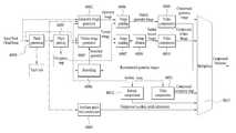
도면은 어큐판시 맵(occupancy map), 지오메트리 이미지(geometry image), 텍스쳐 이미지(texture image), 오실러리 패치 정보(auxiliary patch information)을 생성하고 압축하기 위한 V-PCC encoding process를 도시하여 보여주고 있다. 도4의 V-PCC 인코딩 프로세스는 도1의 포인트 클라우드 비디오 인코더(10002)에 의해 처리될 수 있다. 도4의 각 구성요소는 소프트웨어, 하드웨어, 프로세서 및/또는 그것들의 조합에 의해 수행될 수 있다.The figure shows the V-PCC encoding process for generating and compressing an occupancy map, a geometry image, a texture image, and auxiliary patch information. . The V-PCC encoding process of FIG. 4 may be processed by the point
패치 제너레이션(patch generation, 40000) 또는 패치 제너레이터는 포인트 클라우드 프레임(포인트 클라우드 데이터를 포함하는 비트스트림의 형태일 수 있다)을 수신한다. 패치 제너레이션부(40000)는 포인트 클라우드 데이터로부터 패치를 생성한다. 또한, 패치 생성에 관한 정보를 포함하는 패치 인포를 생성한다.A patch generation (40000) or patch generator receives a point cloud frame (which may be in the form of a bitstream containing point cloud data). The
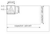
패치 패킹(patch packing, 40001) 또는 패치 패커는 포인트 클라우드 데이터에 대한 패치를 패킹한다. 예를 들어, 하나 또는 하나 이상의 패치들이 패킹될 수 있다. 또한, 패치 패킹에 관한 정보를 포함하는 어큐판시 맵을 생성한다.Patch packing (40001) or patch packer packs patches for point cloud data. For example, one or more patches may be packed. In addition, an accumulatory map including information on patch packing is generated.
지오메트리 이미지 제너레이션(geometry image generation, 40002) 또는 지오메트리 이미지 제너레이터는 포인트 클라우드 데이터, 패치, 및/또는 패킹된 패치에 기반하여 지오메트리 이미지를 생성한다. 지오메트리 이미지는 포인트 클라우드 데이터에 관한 지오메트리를 포함하는 데이터를 말한다.A geometry image generation (40002) or geometry image generator generates a geometry image based on point cloud data, patches, and/or packed patches. The geometry image refers to data including geometry related to point cloud data.
텍스쳐 이미지 제너레이션(texture image generation, 40003) 또는 텍스쳐 이미지 제너레이터는 포인트 클라우드 데이터, 패치, 및/도는 패킹된 패치에 기반하여 텍스쳐 이미지를 생성한다. 또한, 재구성된(리컨스트럭션된) 지오메트리 이미지를 패치 인포에 기반하여 스무딩(번호)이 스무딩 처리를 하여 생성된 스무딩된 지오메트리에 더 기초하여, 텍스쳐 이미지를 생성할 수 있다.A texture image generation (40003) or texture image generator generates a texture image based on point cloud data, patches, and/or packed patches. In addition, a texture image may be generated further based on a smoothed geometry generated by performing a smoothing (number) smoothing process on the reconstructed (reconstructed) geometry image based on patch information.
스무딩(smoothing, 40004) 또는 스무더는 이미지 데이터에 포함된 에러를 완화 또는 제거할 수 있다. 예를 들어, 재구성된 지오메트리 이미지를 패치 인포에 기반하여 데이터 간 에러를 유발할 수 있는 부분을 부드럽게 필터링하여 스무딩된 지오메트리를 생성할 수 있다.A smoothing (40004) or smoother may mitigate or remove errors contained in image data. For example, a smoothed geometry may be generated by gently filtering the reconstructed geometry image based on the patch information to gently filter a portion that may cause an error between data.
오실러리 패치 인포 컴프레션(auxillary patch info compression, 40005) 또는 오실러리 패치 정보 컴프레서는 패치 생성 과정에서 생성된 패치 정보와 관련된 부가적인 패치 정보를 컴프레션한다. 또한, 컴프레스된 오실러리 패치 인포를 멀티플레서에 전달하고, 지오메트리 이미지 제너레이션(40002)도 오실러리 패치 정보를 이용할 수 있다.An auxillary patch info compression (40005) or auxillary patch information compressor compresses additional patch information related to patch information generated in a patch generation process. In addition, the compressed oscillation patch information may be transmitted to the multiplexer, and the
이미지 패딩(image padding, 40006, 40007) 또는 이미지 패더는 지오메트리 이미지 및 텍스쳐 이미지를 각각 패딩할 수 있다. 패딩 데이터가 지오메트리 이미지 및 텍스쳐 이미지에 패딩될 수 있다.Image padding (40006, 40007) or image padding may pad a geometry image and a texture image, respectively. Padding data may be padded to the geometry image and the texture image.
그룹 딜레이션(group dilation, 40008) 또는 그룹 딜라이터는 이미지 패딩과 유사하게, 텍스쳐 이미지에 데이터를 부가할 수 있다. 부가 데이터가 텍스쳐 이미지에 삽입될 수 있다.A group dilation (40008) or group delimiter may append data to a textured image, similar to image padding. Additional data may be inserted into the texture image.
비디오 컴프레션(video compression, 40009, 40010, 40011) 또는 비디오 컴프레서는 패딩된 지오메트리 이미지, 패딩된 텍스쳐 이미지 및/또는 어큐판시 맵을 각각 컴프레션할 수 있다. 컴프레션은 지오메트리 정보, 텍스쳐 정보, 어큐판시 정보 등을 인코딩할 수 있다.A video compression (40009, 40010, 40011) or video compressor may compress a padded geometry image, a padded texture image, and/or an accumulatory map, respectively. Compression may encode geometry information, texture information, accumulatory information, and the like.
엔트로피 컴프레션(entropy compression, 40012) 또는 엔트로피 컴프레서는 어큐판시 맵을 엔트로피 방식에 기반하여 컴프레션(예를 들어, 인코딩)할 수 있다.The entropy compression (40012) or entropy compressor may compress (eg, encode) the accumulatory map based on an entropy scheme.
실시예들에 따라, 포인트 클라우드 데이터가 로스리스(lossless)한 경우 및/또는 로시(lossy)한 경우에 따라서, 엔트로피 컴프레션 및/또는 비디오 컴프레션이 각각 수행될 수 있다.According to embodiments, entropy compression and/or video compression may be respectively performed according to a case in which point cloud data is lossless and/or lossy.
멀티플렉서(multiplexer, 40013)는 컴프레스된 지오메트리 이미지, 컴프레스된 텍스쳐 이미지, 컴프레스된 어큐판시 맵을 비트스트림으로 멀티플렉싱한다.A
실시예들에 따른 도4의 각 프로세스의 상세한 동작은 다음과 같다.The detailed operation of each process of FIG. 4 according to the embodiments is as follows.
패치 제너레이션(Patch generation, 40000)Patch generation (40000)
패치 제너레이션(Patch generation) 과정은 포인트 클라우드를 2D 이미지에 맵핑 (mapping)하기 위하여, 맵핑을 수행하는 단위인 patch로 point cloud를 분할하는 과정을 의미한다. Patch generation 과정은 다음과 같이 노멀(normal) 값 계산, 세그멘테이션(segmentation), 패치(patch) 분할의 세 단계로 구분될 수 있다.The patch generation process refers to a process of dividing the point cloud into patches, which are units for performing mapping, in order to map the point cloud to a 2D image. The patch generation process can be divided into three steps: normal value calculation, segmentation, and patch division as follows.
도5를 참조하여, 노멀 값 계산 과정을 구체적으로 설명한다.Referring to FIG. 5 , a process of calculating a normal value will be described in detail.
도5는 실시예들에 따른 서페이스(Surface)의 탄젠트 플렌(tangent plane) 및 노멀 벡터(normal vector)의 예시를 나타낸다.5 shows an example of a tangent plane and a normal vector of a surface according to embodiments.
도5의 서페이스는 도4의 V-PCC 인코딩 프로세스의 패치 제너레이션 과정(40000)에서 다음과 같이 이용된다.The surface of FIG. 5 is used as follows in the
패치 제너레이션 관련하여 노멀(Normal) 계산:Calculating normals for patch generation:
포인트 클라우드를 이루는 각 점(예를 들어, 포인트)들은 고유의 방향을 가지고 있는데 이것은 normal이라는 3차원 vector로 표현된다. K-D tree 등을 이용하여 구해지는 각 점들의 인접점들 (neighbors)을 이용하여, 도면과 같은 point cloud의 surface를 이루는 각 점들의 tangent plane 및 normal vector를 구할 수 있다. 인접점들을 찾는 과정에서의 search range는 사용자에 의해 정의될 수 있다.Each point (eg, point) constituting the point cloud has its own direction, which is expressed as a three-dimensional vector called normal. The tangent plane and normal vector of each point constituting the surface of the point cloud as shown in the drawing can be obtained by using the neighbors of each point obtained using a K-D tree, etc. The search range in the process of finding adjacent points can be defined by the user.
탄젠트 플레인(tangent plane): surface의 한 점을 지나면서 surface 위의 곡선에 대한 접선을 완전이 포함하고 있는 평면을 나타낸다.Tangent plane: A plane passing through a point on the surface and completely containing the tangent to the curve on the surface.
도6은 실시예들에 따른 포인트 클라우드의 바운딩 박스(bounding box)의 예시를 나타낸다.6 shows an example of a bounding box of a point cloud according to embodiments.
실시예들에 따른 방법/장치, 예를 들어, 패치 제너레이션이 포인트 클라우드 데이터로부터 패치를 생성하는 과정에서 바운딩 박스를 이용할 수 있다.A method/apparatus according to embodiments, for example, patch generation may use a bounding box in a process of generating a patch from point cloud data.
실시예들에 따른 바운딩 박스란, 포인트 클라우드 데이터를 3D 공간 상에서 육면체에 기반하여 분할하는 단위의 박스를 말한다.The bounding box according to the embodiments refers to a box of units for dividing point cloud data based on a hexahedron in 3D space.
바운딩 박스는 포인트 클라우드 데이터의 대상이 되는 오브젝트를 3D 공간 상의 육면체에 기반하여 각 육면체의 평면에 프로젝션하는 과정에서 이용될 수 있다. 바운딩 박스는 도1의 포인트 클라우드 비디오 획득부(10000), 포인트 클라우드 비디오 인코더(10002)에 의해 생성되고 처리될 수 있다. 또한, 바운딩 박스에 기반하여, 도2의 V-PCC 인코딩 프로세스의 패치 제너레이션(40000), 패치 패킹(40001), 지오메트리 이미지 제너레이션(40002), 텍스쳐 이미지 제너레이션(40003)이 수행될 수 있다.The bounding box may be used in the process of projecting an object that is a target of point cloud data on the plane of each cube based on the cube in 3D space. The bounding box may be generated and processed by the point cloud
패치 제너레이션 관련하여 세그멘테이션(Segmentation)Segmentation in relation to patch generation
세그멘테이션(Segmentation)은 이니셜 세그멘테이션(initial segmentation)과 리파인 세그멘테이션(refine segmentation)의 두 과정으로 이루어 진다.Segmentation consists of two processes: initial segmentation and refine segmentation.
실시예들에 따른 포인트 클라우드 인코더(10002)는 포인트를 바운딩박스의 한 면에 프로젝션한다. 구체적으로, Point cloud를 이루는 각 점들은 도면과 같이 point cloud를 감싸는 6개의 bounding box의 면들 중 하나의 면에 projection되는데, initial segmentation은 각 점들이 projection될 bounding box의 평면들 중 하나를 결정하는 과정이다.The
6개의 각 평면들과 대응되는 normal값인
(1.0, 0.0, 0.0), (0.0, 1.0, 0.0), (0.0, 0.0, 1.0), (-1.0, 0.0, 0.0), (0.0, -1.0, 0.0), (0.0, 0.0, -1.0).(1.0, 0.0, 0.0), (0.0, 1.0, 0.0), (0.0, 0.0, 1.0), (-1.0, 0.0, 0.0), (0.0, -1.0, 0.0), (0.0, 0.0, -1.0) .
다음의 수식과 같이 앞서 normal 값 계산과정에서 얻은 각 점들의 normal 값(


결정된 평면은 0~5 중 하나의 index 형태의 값 (cluster index) 으로 식별될 수 있다.The determined plane may be identified as a value (cluster index) of one of 0 to 5 in the form of an index.
Refine segmentation은 앞서 initial segmentation 과정에서 결정된 point cloud를 이루는 각 점의projection 평면을 인접 점들의 projection 평면을 고려하여 개선하는 과정이다. 이 과정에서는 앞서 initial segmentation 과정에서 projection 평면 결정을 위해 고려된 각 포인트의 normal과 bounding box의 각 평면의 normal 값과의 유사 정도를 이루는 score normal과 함께, 현재 점의 projection 평면과 인접 점들의 projection 평면과의 일치 정도를 나타내는 score smooth가 동시에 고려될 수 있다.Refine segmentation is a process of improving the projection plane of each point constituting the point cloud determined in the initial segmentation process in consideration of the projection plane of adjacent points. In this process, the projection plane of the current point and the projection plane of the adjacent points along with the score normal that is similar to the normal value of each point and the normal value of each plane of the bounding box considered for the projection plane determination in the initial segmentation process earlier. Score smooth, which indicates the degree of agreement with , can be considered at the same time.
Score smooth는 score normal에 대하여 가중치를 부여하여 고려될 수 있으며, 이 때 가중치 값은 사용자에 의해 정의될 수 있다. Refine segmentation은 반복적으로 수행될 수 있으며, 반복 횟수 또한 사용자에 의해 정의될 수 있다.Score smooth can be considered by assigning weights to the score normal, and in this case, the weight value can be defined by the user. Refine segmentation may be repeatedly performed, and the number of repetitions may also be defined by the user.
패치 제너레이션 관련하여 Patch 분할 (segment patches)Segment patches in relation to patch generation
Patch 분할은 앞서 initial/refine segmentation 과정에서 얻은 point cloud를 이루는 각 점들의 projection 평면 정보를 바탕으로, 전체 point cloud를 인접한 점들의 집합인 patch로 나누는 과정이다. Patch 분할은 다음과 같은 단계들로 구성될 수 있다.Patch segmentation is a process of dividing the entire point cloud into patches, which are sets of adjacent points, based on the projection plane information of each point constituting the point cloud obtained in the initial/refine segmentation process. Patch division can be composed of the following steps.
1) K-D tree 등을 이용하여 point cloud를 이루는 각 점들의 인접 점들을 산출한다. 최대 인접점으 개수는 사용자에 의해 정의될 수 있다.1) Calculate the adjacent points of each point constituting the point cloud using K-D tree, etc. The maximum number of adjacent points may be defined by the user.
2) 인접 점들이 현재의 점과 동일한 평면에 projection 될 경우 (동일한 cluster index 값을 가질 경우) 현재의 점과 해당 인접 점들을 하나의 patch로 추출한다.2) When adjacent points are projected on the same plane as the current point (if they have the same cluster index value), the current point and its adjacent points are extracted as a single patch.
3) 추출된 patch의 geometry 값들을 산출한다. 자세한 과정은 이하에서 설명한다.3) Calculate the geometry values of the extracted patch. A detailed process will be described below.
4) 추출되지 않은 점들이 없어질 때까지 2)~4)과정을 반복한다.4) Repeat steps 2) to 4) until the unextracted points disappear.
Patch 분할 과정을 통해 각 patch의 크기 및 patch별 occupancy map, geometry image, texture image 등이 결정된다.Through the patch division process, the size of each patch and the occupancy map, geometry image, and texture image for each patch are determined.
도7은 실시예들에 따른 어큐판시 맵(occupancy map)의 개별 패치(patch) 위치 결정의 예시를 나타낸다.7 shows an example of individual patch location determination of an occupancy map according to embodiments.
실시예들에 따른 포인트 클라우드 인코더(10002)는 패치 패킹 및 어큐판시 맵을 생성할 수 있다.The
패치 패킹 및 어큐판시 맵 생성(Patch packing & Occupancy map generation, 40001)Patch packing & Occupancy map generation, 40001
본 과정은 앞서 분할된 patch들을 하나의 2D 이미지에 맵핑하기 위해 개별 patch들의 2D 이미지 내에서의 위치를 결정하는 과정이다. Occupancy map은 2D 이미지의 하나로, 해당 위치에 데이터가 존재하는지 여부를 0 또는 1의 값으로 알려주는 바이너리 맵(binary map)이다. Occupancy map은 블록(block)으로 이루어 지며 block의 크기에 따라 그 해상도가 결정될 수 있는데, 일례로 block 크기가 1*1일 경우 픽셀 (pixel) 단위의 해상도를 갖는다. Block의 크기 (occupancy packing block size)는 사용자에 의해 결정될 수 있다.This process is a process of determining the positions of individual patches in a 2D image in order to map the previously divided patches to a single 2D image. The occupancy map is one of the 2D images, and is a binary map that indicates whether data exists in the corresponding location with a value of 0 or 1. The occupancy map consists of blocks, and the resolution can be determined according to the size of the block. For example, when the block size is 1*1, it has a pixel unit resolution. The size of the block (occupancy packing block size) may be determined by the user.
Occupancy map 내에서 개별 patch의 위치를 결정하는 과정은 다음과 같이 구성될 수 있다.The process of determining the location of an individual patch in the occupancy map can be configured as follows.
1) 전체 occupancy map의 값들을 모두 0으로 설정한다.1) All occupancy map values are set to 0.
2) occupancy map 평면에 존재하는 수평 좌표가 [0, occupancySizeU - patch.sizeU0), 수직 좌표가 [0, occupancySizeV - patch.sizeV0) 범위에 있는 점 (u, v)에 patch를 위치시킨다.2) Place the patch at the point (u, v) where the horizontal coordinates on the occupancy map plane are in the range [0, occupancySizeU - patch.sizeU0) and the vertical coordinates are in the range [0, occupancySizeV - patch.sizeV0).
3) patch 평면에 존재하는 수평 좌표가 [0, patch.sizeU0), 수직 좌표가 [0, patch.sizeV0) 범위에 있는 점 (x, y)를 현재 점(포인트)으로 설정한다.3) Set the current point (point) to a point (x, y) where the horizontal coordinates of the patch plane are in the range [0, patch.sizeU0) and the vertical coordinates are [0, patch.sizeV0).
4) 점 (x, y)에 대하여, patch occupancy map의 (x, y) 좌표 값이 1이고 (patch 내 해당 지점에 데이터가 존재하고), 전체 occupancy map의 (u+x, v+y) 좌표 값이 1 (이전 patch에 의해 occupancy map이 채워진 경우) raster order 순으로 (x, y) 위치를 변경하여 3)~4)의 과정을 반복한다. 그렇지 않을 경우, 6)의 과정을 수행한다.4) For a point (x, y), the (x, y) coordinate value of the patch occupancy map is 1 (data exists at that point in the patch), and (u+x, v+y) of the entire occupancy map If the coordinate value is 1 (when the occupancy map is filled by the previous patch), repeat the process of 3)~4) by changing the (x, y) position in raster order. Otherwise, proceed with step 6).
5) raster order 순으로 (u, v) 위치를 변경하여 3)~5)의 과정을 반복한다.5) Repeat steps 3) to 5) by changing the (u, v) positions in the order of raster order.
6) (u, v)를 해당 patch의 위치로 결정하고, patch의 occupancy map 데이터를 전체 occupancy map의 해당 부분에 할당(copy)한다.6) Determine (u, v) as the location of the patch, and assign (copy) the patch's occupancy map data to the corresponding part of the entire occupancy map.
7) 다음 patch에 대하여 2)~7)의 과정을 반복한다.7) Repeat steps 2) to 7) for the next patch.
어큐판시 사이즈U(occupancySizeU): occupancy map의 너비(width)를 나타내며, 단위는 어큐판시 패킹 사이즈 블록(occupancy packing block size) 이다.Occupancy SizeU (occupancySizeU): Indicates the width of the occupancy map, and the unit is the occupancy packing block size.
어큐판시 사이즈V(occupancySizeV): occupancy map의 높이(height)를 나타내며, 단위는 occupancy packing block size 이다.occupancySizeV: Indicates the height of the occupancy map, and the unit is the occupancy packing block size.
패치 사이즈 U0(patch.sizeU0): occupancy map의 width를 나타내며, 단위는 occupancy packing block size 이다.Patch size U0 (patch.sizeU0): Indicates the width of the occupancy map, and the unit is the occupancy packing block size.
패치 사이즈 V0(patch.sizeV0): occupancy map의 height를 나타내며, 단위는 occupancy packing block size 이다.Patch size V0 (patch.sizeV0): Indicates the height of the occupancy map, and the unit is the occupancy packing block size.
예를 들어, 도7과 같이 어큐판사 패킹 사이즈 블록에 해당하는 박스 내 패치 사이즈를 갖는 패치에 대응하는 박스가 존재하고, 박스 내 포인트(x, y)가 위치할 수 있다.For example, as shown in FIG. 7 , a box corresponding to a patch having a patch size in a box corresponding to an Accupansa packing size block exists, and points (x, y) in the box may be located.
도8은 실시예들에 따른 노멀(normal), 탄젠트(tangent), 바이탄젠트(bitangent) 축의 관계의 예시를 나타낸다.8 shows an example of the relationship between normal, tangent, and bitangent axes according to embodiments.
실시예들에 따른 포인트 클라우드 인코더(10002)는 지오메트리 이미지를 생성할 수 있다. 지오메트리 이미지란, 포인트 클라우드의 지오메트리 정보를 포함하는 이미지 데이터를 의미한다. 지오메트리 이미지 생성 과정은 도8의 패치의 세 가지 축(노멀, 탄젠트, 바이탄젠트)을 이용할 수 있다.The
지오메트리 이미지 생성(Geometry image generation, 40002)Geometry image generation (40002)
본 과정에서는 개별 patch의 geometry image를 구성하는 depth 값들을 결정하고, 앞서 패치 패킹(patch packing) 과정에서 결정된 patch의 위치를 바탕으로 전체 geometry image를 생성한다. 개별 patch의 geometry image를 구성하는 depth 값들을 결정하는 과정은 다음과 같이 구성될 수 있다.In this process, the depth values constituting the geometry image of each patch are determined, and the entire geometry image is created based on the location of the patch determined in the patch packing process. The process of determining the depth values constituting the geometry image of an individual patch can be configured as follows.
1) 개별 patch의 위치, 크기 관련 파라미터들이 산출된다. 파라미터들은 다음과 같은 정보들을 포함할 수 있다.1) The parameters related to the location and size of individual patches are calculated. The parameters may include the following information.
normal 축을 나타내는 index: normal은 앞서 patch generation 과정에서 구해지며, tangent 축은 normal과 직각인 축들 중 patch image의 수평(u)축과 일치하는 축이며, bitangent 축은 normal과 직각인 축들 중 patch image의 수직(v)축과 일치하는 축으로, 세 가지 축은 도면과 같이 표현될 수 있다.Index representing the normal axis: normal is obtained in the patch generation process above, the tangent axis is the axis that coincides with the horizontal (u) axis of the patch image among the axes perpendicular to the normal, and the bitangent axis is the vertical (vertical) axis of the patch image among the axes perpendicular to the normal. v) As an axis coincident with the axis, the three axes can be expressed as shown in the drawing.
도9는 실시예들에 따른 프로젝션 모드의 최소 모드 및 최대 모드의 구성의 예시를 나타낸다.9 shows an example of the configuration of the minimum mode and the maximum mode of the projection mode according to the embodiments.
실시예들에 따른 포인트 클라우드 인코더(10002)는 지오메트리 이미지를 생성하기 위해서 패치에 기반한 프로젝션을 수행할 수 있고, 실시예들에 따른 프로젝션의 모드는 최소 모드 및 최대 모드가 있다.The
patch의 3D 공간 좌표: patch를 감싸는 최소 크기의 bounding box를 통해 산출될 수 있다. 예를 들어, patch의 tangent 방향 최소값 (patch 3d shift tangent axis), patch의 bitangent 방향 최소값 (patch 3d shift bitangent axis), patch의 normal 방향 최소값 (patch 3d shift normal axis) 등이 포함될 수 있다.3D spatial coordinates of the patch: It can be calculated through the smallest size bounding box surrounding the patch. For example, the minimum value in the tangent direction of the patch (patch 3d shift tangent axis), the minimum value in the bitangent direction of the patch (patch 3d shift bitangent axis), the minimum value in the normal direction of the patch (patch 3d shift normal axis), etc. may be included.
patch의 2D 크기: patch가 2D 이미지로 패킹될 때의 수평, 수직 방향 크기를 나타낸다. 수평 방향 크기 (patch 2d size u)는 bounding box의 tangent 방향 최대값과 최소값의 차이로, 수직 방향 크기 (patch 2d size v)는 bounding box의 bitangent 방향 최대값과 최소값의 차이로 구해질 수 있다.2D size of patch: Shows the horizontal and vertical size of the patch when it is packed into a 2D image. The horizontal size (patch 2d size u) is the difference between the maximum and minimum values in the tangent direction of the bounding box, and the vertical size (patch 2d size v) is the difference between the maximum and minimum values in the bitangent direction of the bounding box.
2) Patch의 projection mode를 결정한다. Projection mode는 최소 모드(min mode)와 최대 모드(max mode) 중 하나일 수 있다. Patch의 geometry 정보는 depth 값으로 표현되는데, patch의 normal 방향으로 patch를 이루는 각 점들을 projection 할 때 depth 값의 최대 값으로 구성되는 이미지와 최소값으로 구성되는 이미지 두 계층(layer)의 이미지들이 생성될 수 있다.2) Decide the projection mode of the patch. The projection mode may be one of a min mode and a max mode. The geometry information of the patch is expressed as a depth value. When each point constituting the patch is projected in the normal direction of the patch, the image composed of the maximum value of the depth value and the image composed of the minimum value will be created. can
두 계층의 이미지 d0와 d1을 생성함에 있어, min mode일 경우 도면과 같이 최소 depth가 d0에 구성되고, 최소 depth로부터 surface thickness 이내에 존재하는 최대 depth가 d1으로 구성될 수 있다.In generating two-layer images d0 and d1, in min mode, the minimum depth is configured in d0 as shown in the figure, and the maximum depth existing within the surface thickness from the minimum depth can be configured as d1.
예를 들어, 포인트 클라우드가 도면과 같이 2D에 위치하는 경우, 복수의 포인트들을 포함하는 복수의 패치들이 있을 수 있다. 도면과 같이 같은 스타일의 음영으로 표시된 포인트들이 동일한 패치에 속할 수 있음을 나타낸다. 빈 칸으로 표시된 포인트들의 패치를 프로젝션하는 과정을 도면이 나타낸다.For example, when the point cloud is located in 2D as shown in the drawing, there may be a plurality of patches including a plurality of points. As shown in the drawing, the shaded points of the same style indicate that they may belong to the same patch. The drawing shows the process of projecting a patch of points marked with blank spaces.
빈 칸으로 표시된 포인트들을 좌측/우측으로 프로젝션하는 경우, 좌측을 기준으로 depth를 0, 1, 2,..6, 7, 8, 9 와 같이 1씩 증가하면서 우측으로 포인트들의 depth산출을 위한 숫자를 표기할 수 있다.When the blanked points are projected to the left/right, the depth is increased by 1, such as 0, 1, 2,..6, 7, 8, 9, based on the left, and the number for calculating the depth of the points to the right. can be indicated.
프로젝션 모드(Projection mode)는 사용자 정의에 의해 모든 point cloud에 동일한 방법이 적용되거나, frame 또는 patch 별로 다르게 적용될 수 있다. Frame 또는 patch 별로 다른 projection mode가 적용될 경우, 압축 효율을 높이거나 소실 점 (missed point)을 최소화 할 수 있는 projection mode가 적응적으로 선택될 수 있다.In the projection mode, the same method is applied to all point clouds by user definition, or it can be applied differently for each frame or patch. When a different projection mode is applied to each frame or patch, a projection mode capable of increasing compression efficiency or minimizing a missed point may be adaptively selected.
3) 개별 점들의 depth 값을 산출한다.3) Calculate the depth value of each point.
최소 모드(Min mode)일 경우 각 점의 normal 축 최소값에 patch의 normal 방향 최소값 (patch 3d shift normal axis)에서 1)의 과정에서 산출된 patch의 normal 방향 최소값 (patch 3d shift normal axis)을 뺀 값인 depth0로 d0 이미지를 구성한다. 동일 위치에 depth0와 surface thickness 이내의 범위에 또 다른 depth 값이 존재할 경우, 이 값을 depth1으로 설정한다. 존재하지 않을 경우 depth0의 값을 depth1에도 할당한다. Depth1 값으로 d1 이미지를 구성한다.In the case of min mode, it is a value obtained by subtracting the minimum value of the normal axis of each point from the minimum value of the patch normal direction (patch 3d shift normal axis) and the minimum value of the patch normal direction calculated in the process of 1) (patch 3d shift normal axis). Construct the d0 image with depth0. If there is another depth value within the range within depth0 and surface thickness at the same location, set this value to depth1. If it does not exist, the value of depth0 is also assigned to depth1. Construct the d1 image with the Depth1 value.
예를 들어, d0의 포인트들의 depth를 결정함에 있어 최소값이 산출될 수 있다(4 2 4 4 0 6 0 0 9 9 0 8 0). 그리고, d1의 포인트들의 depth를 결정함에 있어 두 개 이상의 포인트들 중 큰 값이 산출되거나, 하나의 포인트만 있는 경우 그 값이 산출될 수 있다(4 4 4 4 6 6 6 8 9 9 8 8 9). 또한, 패치의 포인트들이 부호화되고, 재구성(reconstruct) 되는 과정에서 일부 포인트가 손실될 수 있다(예를 들어, 도면은 8개의 포인트가 손실되었다).For example, in determining the depth of the points of d0, a minimum value may be calculated (4 2 4 4 0 6 0 0 9 9 0 8 0). And, in determining the depth of the points of d1, a larger value among two or more points may be calculated, or if there is only one point, the value may be calculated (4 4 4 4 6 6 6 8 9 9 8 8 9) ). Also, some points may be lost in the process of coded and reconstructed points of the patch (eg, 8 points are lost in the figure).
맥스 모드(Max mode)일 경우 각 점의 normal 축 최대값에 patch의 normal 방향 최소값 (patch 3d shift normal axis)에서 1)의 과정에서 산출된 patch의 normal 방향 최소값 (patch 3d shift normal axis)을 뺀 값인 depth0로 d0 이미지를 구성한다. 동일 위치에 depth0와 surface thickness 이내의 범위에 또 다른 depth 값이 존재할 경우, 이 값을 depth1으로 설정한다. 존재하지 않을 경우 depth0의 값을 depth1에도 할당한다. Depth1 값으로 d1 이미지를 구성한다.In the case of Max mode, the maximum value of the normal axis of each point is subtracted from the minimum value in the normal direction of the patch (patch 3d shift normal axis), and the minimum value in the normal direction of the patch calculated in the process of 1) (patch 3d shift normal axis) is subtracted. Construct the d0 image with the value depth0. If there is another depth value within the range within depth0 and surface thickness at the same location, set this value to depth1. If it does not exist, the value of depth0 is also assigned to depth1. Construct the d1 image with the Depth1 value.
예를 들어, d0의 포인트들의 depth를 결정함에 있어 최대값이 산출될 수 있다(4 4 4 4 6 6 6 8 9 9 8 8 9). 그리고, d1의 포인트들의 depth를 결정함에 있어 두 개 이상의 포인트들 중 작은 값이 산출되거나, 하나의 포인트만 있는 경우 그 값이 산출 될 수 있다(4 2 4 4 5 6 0 6 9 9 0 8 0). 또한, 패치의 포인트들이 부호화되고, 재구성(reconstruct) 되는 과정에서 일부 포인트가 손실될 수 있다(예를 들어, 도면은 6개의 포인트가 손실되었다).For example, a maximum value may be calculated in determining the depth of the points of d0 (4 4 4 4 6 6 6 8 9 9 8 8 9). And, in determining the depth of the points of d1, a smaller value may be calculated among two or more points, or if there is only one point, the value may be calculated (4 2 4 4 5 6 0 6 9 9 0 8 0) ). Also, some points may be lost in the process of coded and reconstructed points of the patch (eg, 6 points are lost in the drawing).
위와 같은 과정을 통해 생성된 개별 patch의 geometry image를 앞서 patch packing 과정에서 결정된 patch의 위치 정보를 이용하여 전체 geometry image에 배치시킴으로써 전체 geometry image를 생성할 수 있다.The entire geometry image can be created by placing the geometry image of an individual patch created through the above process on the entire geometry image using the patch location information determined in the patch packing process.
생성된 전체 geometry image의 d1 계층은 여러 가지 방법으로 부호화 될 수 있다. 첫 번째는 앞서 생성한 d1 이미지의 depth값들을 그대로 부호화 (absolute d1 method)하는 방법이다. 두 번째는 앞서 생성한 d1 이미지의 depth값과 d0 이미지의 depth값이 차이 값을 부호화 (differential method)하는 방법이다.The d1 layer of the generated entire geometry image can be encoded in several ways. The first is a method of encoding the depth values of the previously generated d1 image as it is (absolute d1 method). The second is a method of encoding a difference value between the depth value of the previously generated d1 image and the depth value of the d0 image (differential method).
이와 같은 d0, d1 두 계층의 depth 값을 이용한 부호화 방법은 두 depth 사이에 또 다른 점들이 존재할 경우 해당 점의 geometry 정보를 부호화 과정에서 잃어버리기 때문에, 무손실 압축 (lossless coding)을 위해 Enhanced-Delta-Depth (EDD) code를 이용할 수도 있다.In this encoding method using the depth values of the two layers d0 and d1, if there are other points between the two depths, the geometry information of the corresponding point is lost during the encoding process. Therefore, for lossless coding, Enhanced-Delta- Depth (EDD) codes may also be used.
도10을 참조하여, EDD code를 구체적으로 설명한다.With reference to FIG. 10, the EDD code will be described in detail.
도10은 실시예들에 따른 EDD 코드의 예시를 나타낸다.10 shows an example of an EDD code according to embodiments.
포인트 클라우드 인코더(10002) 및/또는 V-PCC 인코딩의 일부/전체 프로세스(예를 들어, 비디오 컴프레스(40009)) 등은 EOD코드에 기반하여 포인트들의 지오메트리 정보를 인코딩할 수 있다.The
EDD code는 도면과 같이, d1을 포함하여 surface thickness 범위 내의 모든 점들의 위치를 이진으로 부호화 하는 방법이다. 일례로 도면의 좌측에서 두 번째 열에 포함되는 점들의 경우, D0 위쪽으로 첫 번째, 네 번째 위치에 점들이 존재하고, 두 번째와 세 번째 위치는 비어있기 때문에 0b1001 (=9)의 EDD code로 표현될 수 있다. D0와 함께 EDD code를 부호화하여 보내 주면 수신단에서는 모든 점들의 geometry 정보를 손실 없이 복원할 수 있게 된다.EDD code is a method of binary encoding the positions of all points within the surface thickness range including d1 as shown in the figure. For example, in the case of points included in the second column from the left of the drawing, the points are present in the first and fourth positions above D0, and the second and third positions are empty, so it is expressed as an EDD code of 0b1001 (=9) can be If the EDD code is encoded and sent together with D0, the receiving end can restore geometry information of all points without loss.
예를 들어, 기준 포인트 위로 포인트가 존재하면 1이고 포인트가 존재하지 않으면 0이 되어 4개의 비트들에 기반하여 코드가 표현될 수 있다.For example, if a point exists above the reference point, it becomes 1, and if the point does not exist, it becomes 0, so that a code may be expressed based on 4 bits.
스무딩(Smoothing, 40004)Smoothing (40004)
스무딩(Smoothing)은 압축 과정에서 발생하는 화질의 열화로 인해 patch 경계면에서 발생할 수 있는 불연속성을 제거하기 위한 작업이며, 포인트 클라우드 인코더 또는 스무더에 의해 수행될 수 있다.Smoothing is an operation to remove discontinuities that may occur at the patch interface due to deterioration of image quality that occurs during the compression process, and may be performed by a point cloud encoder or a smoother.
1) geometry image로부터 point cloud를 재생성(reconstruction)한다. 본 과정은 앞서 설명한 geometry image 생성의 역과정이라고 할 수 있다. 예를 들어, 인코딩의 역과정이 리컨스트럭션일 수 있다.1) Reconstruct the point cloud from the geometry image. This process can be said to be the reverse process of the geometry image creation described above. For example, the reverse process of encoding may be reconstruction.
2) K-D tree 등을 이용하여 재생성된 point cloud를 구성하는 각 점들의 인접점들을 산출한다.2) Calculate the adjacent points of each point constituting the regenerated point cloud using K-D tree, etc.
3) 각 점들에 대하여, 해당 점이 patch 경계면에 위치하는지를 판단한다. 일례로 현재 점과 다른 projection 평면 (cluster index)을 갖는 인접점이 존재할 경우, 해당 점은 patch 경계면에 위치한다고 판단할 수 있다.3) For each point, it is determined whether the point is located on the patch boundary. For example, if an adjacent point having a projection plane (cluster index) different from the current point exists, it can be determined that the point is located on the patch boundary.
4) patch 경계면에 존재할 경우, 해당 점을 인접점들의 무게중심 (인접점들의 평균 x, y, z 좌표에 위치)으로 이동시킨다. 즉, geometry 값을 변경시킨다. 그렇지 않을 경위 이전 geometry 값을 유지한다.4) If present on the patch boundary, the point is moved to the center of gravity of the adjacent points (located at the average x, y, z coordinates of the adjacent points). That is, it changes the geometry value. Otherwise, the previous geometry value is maintained.
도11은 실시예들에 따른 인접점들의 컬러(color) 값들을 이용한 리컬러링(recoloring)의 예시를 나타낸다.11 shows an example of recoloring using color values of adjacent points according to embodiments.
실시예들에 따른 포인트 클라우드 인코더 또는 텍스쳐 이미지 제너레이터(40003)은 리컬러리링에 기반하여 텍스쳐 이미지를 생성할 수 있다.The point cloud encoder or
텍스쳐 이미지 생성(Texture image generation, 40003)Texture image generation (40003)
Texture image 생성 과정은 앞서 설명한 geometry image 생성 과정과 유사하게, 개별 patch의 texture image 생성하고, 이들은 결정된 위치에 배치하여 전체 texture image를 생성하는 과정으로 구성된다. 다만 개별 patch의 texture image를 생성하는 과정에 있어서 geometry 생성을 위한 depth 값을 대신하여 해당 위치에 대응되는 point cloud를 구성하는 점의 color 값 (e.g. R, G, B)을 갖는 image가 생성된다.The texture image creation process is similar to the geometry image creation process described above, and consists of creating a texture image of each patch and placing them in a determined position to create an entire texture image. However, in the process of creating the texture image of each patch, an image with color values (e.g. R, G, B) of the point constituting the point cloud corresponding to the location is created instead of the depth value for geometry creation.
Point cloud를 구성하는 각 점의 color 값을 구하는 과정에 있어서 앞서 smoothing 과정을 거친 geometry가 사용될 수 있다. Smoothing된 point cloud는 원본 point cloud에서 일부 점들의 위치가 이동된 상태일 수 있으므로, 변경된 위치에 적합한 color를 찾아내는 리컬러링(recoloring)과정이 필요할 수 있다. Recoloring은 인접점들의 color 값들을 이용하여 수행될 수 있다. 일례로, 도면과 같이 새로운 color값은 최인접점의 color값과 인접점들의 color값들을 고려하여 산출될 수 있다.In the process of obtaining the color value of each point constituting the point cloud, geometry that has undergone the smoothing process before can be used. Since the smoothed point cloud may have the positions of some points moved from the original point cloud, a recoloring process to find a color suitable for the changed position may be required. Recoloring may be performed using color values of adjacent points. For example, as shown in the drawing, a new color value may be calculated in consideration of the color value of the closest point and the color values of the adjacent points.
예를 들어, 도면을 참조하면, 리컬러링은 포인트에 대한 가장 가까운 오리지날 포인트들의 어트리뷰트 정보의 평균 및/또는 포인트에 대한 가장 가까운 오리지날 위치의 어트리뷰트 정보의 평균에 기반하여 변경된 위치의 적합한 컬러값을 산출할 수 있다.For example, referring to the drawing, the recoloring calculates an appropriate color value of the changed position based on the average of the attribute information of the closest original points to the point and/or the average of the attribute information of the closest original positions to the point can do.
Texture image 또한 d0/d1의 두 계층으로 생성되는 geometry image와 같이 t0/t1의 두 개의 계층 으로 생성될 수 있다.A texture image can also be created with two layers of t0/t1 like a geometry image created with two layers of d0/d1.
오실러리 패치 인포 컴프레션(Auxiliary patch info compression, 40005)Auxiliary patch info compression (40005)
실시예들에 따른 포인트 클라우드 인코더 또는 오실러리 패치 정보 컴프레서는 오실러리 패치 정보(포인트 클라우드에 관한 부가적인 정보)를 컴프레션할 수 있다.The point cloud encoder or oscillation patch information compressor according to the embodiments may compress oscillation patch information (additional information about the point cloud).
오실러리 패치 정보 컴프레서는 앞서 설명한 patch generation, patch packing, geometry generation 과정 등에서 생성된 부가 patch 정보들을 압축(컴프레스)한다. 부가 patch 정보에는 다음과 같은 파라미터들이 포함될 수 있다:The Oscilry patch information compressor compresses (compresses) the additional patch information generated in the patch generation, patch packing, and geometry generation processes described above. Additional patch information may include the following parameters:
프로젝션(projection) 평면 (normal)을 식별하는 인덱스 (클러스터 인덱스, cluster index)Index that identifies the projection plane (normal) (cluster index)
패치의 3D 공간 위치: 패치의 탄젠트 방향 최소값 (patch 3d shift tangent axis), 패치의 바이탄젠트 방향 최소값 (patch 3d shift bitangent axis), 패치의 노멀 방향 최소값 (patch 3d shift normal axis)3D spatial position of the patch: the tangent minimum of the patch (patch 3d shift tangent axis), the minimum of the patch (patch 3d shift bitangent axis), the minimum of the patch in the normal direction (patch 3d shift normal axis)
패치의 2D 공간 위치, 크기: 수평 방향 크기 (patch 2d size u), 수직 방향 크기 (patch 2d size v), 수평 방향 최소값 (patch 2d shift u), 수직 방향 최소값 (patch 2d shift u)2D spatial position and size of patch: horizontal size (patch 2d size u), vertical size (patch 2d size v), horizontal minimum (patch 2d shift u), vertical minimum (patch 2d shift u)
각 블록과 패치의 맵핑 정보: candidate index (위의 patch의 2D 공간 위치, 크기 정보를 기반으로 patch를 순서대로 위치시켰을 때, 한 block에 중복으로 복수 patch가 맵핑될 수 있음. 이때 맵핑되는 patch들이 candidate list를 구성하며, 이 list 중 몇 번째 patch의 data가 해당 block에 존재하는지를 나타내는 index), local patch index (frame에 존재하는 전체 patch들 중 하나를 가리키는 index). Table X는 candidate list와 local patch index를 이용한 block과 patch match 과정을 나타내는 pseudo code이다.Mapping information of each block and patch: Candidate index (When patches are placed in order based on the 2D spatial location and size information of the patch above, multiple patches can be duplicated mapped to one block. At this time, the mapped patches are It composes the candidate list, the index indicating which patch data of the list exists in the corresponding block), and the local patch index (the index indicating one of all patches existing in the frame). Table X is a pseudo code showing the block and patch match process using the candidate list and local patch index.
candidate list의 최대 개수는 사용자에 의해 정의될 수 있다.The maximum number of candidate lists can be defined by the user.
block과 patch 맵핑을 위한 pseudo codePseudo code for block and patch mapping

도12는 실시예들에 따른 푸쉬-풀 백그라운드 필링(push-pull background filling)의 예시를 나타낸다.12 shows an example of push-pull background filling according to embodiments.
이미지 패딩 및 그룹 딜레이션(Image padding and group dilation, 40006, 40007, 40008)Image padding and group dilation (40006, 40007, 40008)
실시예들에 따른 이미지 패더는 푸쉬-풀 백그라운드 필링 방식에 기반하여 패치 영역 외의 공간을 의미 없는 부가적인 데이터로 채울 수 있다.The image fader according to embodiments may fill a space other than the patch area with meaningless additional data based on the push-pull background filling method.
이미지 패딩(Image padding)은 압축 효율 향상을 목적으로 patch 영역 이외의 공간을 의미 없는 데이터로 채우는 과정이다. Image padding을 위해 patch 내부의 경계면 쪽에 해당하는 열 또는 행의 픽셀 값들이 복사되어 빈 공간을 채우는 방법이 사용될 수 있다. 또는 도면과 같이, padding 되지 않은 이미지를 단계적으로 해상도를 줄이고, 다시 해상도를 늘리는 과정에서 낮은 해상도의 이미지로부터 온 픽셀 값들로 빈 공간을 채우는 push-pull background filling 방법이 사용될 수도 있다.Image padding is a process of filling spaces other than the patch area with meaningless data for the purpose of improving compression efficiency. For image padding, a method in which pixel values of columns or rows corresponding to the boundary surface inside the patch are copied to fill the empty space can be used. Alternatively, as shown in the drawing, a push-pull background filling method in which an empty space is filled with pixel values from a low-resolution image in the process of gradually reducing the resolution of the non-padded image and increasing the resolution again may be used.
그룹 딜레이션은 d0/d1, t0/t1 두 계층으로 이루어진 geometry, texture image의 빈 공간을 채우는 방법으로, 앞서 image padding을 통해 산출된 두 계층 빈 공간의 값들을, 두 계층의 동일 위치에 대한 값의 평균값으로 채우는 과정이다.Group dilation is a method of filling the empty space of the geometry and texture image composed of two layers d0/d1 and t0/t1. It is the process of filling in the average value of .
도13은 실시예들에 따른 4*4 크기의 블록(block)에 대해 가능한 트라버설 오더(traversal order)의 예시를 나타낸다.13 shows an example of a possible traversal order for a block of 4*4 size according to embodiments.
오큐판시 맵 컴프레션(Occupancy map compression, 40012, 40011)Occupancy map compression (40012, 40011)
실시예들에 따른 오규판시 맵 컴프레서는 앞서 생성된 occupancy map을 압축할 수 있다. 구체적으로, 손실 (lossy) 압축을 위한 비디오 컴프레션과 무손실 (lossless) 압축을 위한 엔트로피 컴프레션, 두 가지 방법이 존재할 수 있다. 비디오 컴프레션은 이하에서 설명한다.The occupancy map compressor according to the embodiments may compress the previously generated occupancy map. Specifically, there may be two methods: video compression for lossy compression and entropy compression for lossless compression. Video compression is described below.
엔트로피 컴프레션(Entropy compression) 과정은 다음과 같은 과정으로 수행될 수 있다.The entropy compression process may be performed as follows.
1) occupancy map을 구성하는 각 block에 대하여, block이 모두 채워진 경우 1을 부호화 하고 다음 block에 대해 동일 과정을 반복한다. 그렇지 않은 경우 0을 부호화하고, 2)~5)의 과정을 수행한다. .1) For each block constituting the occupancy map, if all blocks are filled,
2) block의 채워진 pixel들에 대해 run-length coding을 수행하기 위한 best traversal order를 결정한다. 도면은 4*4 크기의 block에 대해 가능한 4가지 traversal order를 일례로 보여주고 있다.2) Determine the best traversal order for performing run-length coding on the filled pixels of the block. The figure shows four possible traversal orders for a block of 4*4 size as an example.
도14는 실시예들에 따른 베스트 트라버설 오더의 예시를 나타낸다.14 shows an example of a best traversal order according to embodiments.
상술한 바와 같이 실시예들에 따른 엔트포리 컴프레서는 도면과 같이 트라버설 오더 방식에 기반하여 블록을 코딩(부호화)할 수 있다.As described above, the entry compressor according to the embodiments may code (encode) the block based on the traversal order method as shown in the drawing.
예를 들어, 가능한 traversal order들 중 최소의 run 개수를 갖는 베스트 트라버설 오더(best traversal order)를 선택하여 그 인덱스를 부호화 한다. 일례로 도면은 앞선 도13의 세 번째 traversal order를 선택할 경우이며, 이 경우 run의 개수가 2로 최소화될 수 있으므로 이를 베스트 트라버설 오더로 선택할 수 있다.For example, the index is encoded by selecting the best traversal order having the minimum number of runs among possible traversal orders. As an example, the drawing is a case where the third traversal order of FIG. 13 is selected, and in this case, since the number of runs can be minimized to 2, it can be selected as the best traversal order.
이때 run의 개수를 부호화 한다. 도14의 예에서는 2개의 run이 존재하므로 2가 부호화 된다.At this time, the number of runs is encoded. In the example of FIG. 14, since there are two runs, 2 is coded.
4) 첫 번째 run의 occupancy를 부호화 한다. 도14의 예에서는 첫 번째 run이 채워지지 않은 픽셀들에 해당하므로 0이 부호화된다.4) Encode the occupancy of the first run. In the example of FIG. 14 , 0 is coded because the first run corresponds to unfilled pixels.
5) 개별 run에 대한 (run의 개수만큼의) length를 부호화 한다. 도14의 예에서는 첫 번째 run과 두 번째 run의 length인 6과 10이 순차적으로 부호화된다.5) Encode the length (as much as the number of runs) for each run. In the example of FIG. 14 ,
비디오 컴프레션(Video compression, 40009, 40010, 40011)Video compression (40009, 40010, 40011)
실시예들에 따른 비디오 컴프레서는 HEVC, VVC 등의 2D video codec 등을 이용하여, 앞서 설명한 과정으로 생성된 geometry image, texture image, occupancy map image 등의 시퀀스를 부호화한다.The video compressor according to the embodiments encodes a sequence such as a geometry image, a texture image, and an occupancy map image generated by the above-described process by using a 2D video codec such as HEVC or VVC.
도15는 실시예들에 따른 2D 비디오/이미지 인코더(2D video/image Encoder)의 예시를 나타낸다.15 shows an example of a 2D video/image encoder according to embodiments.
도면은 상술한 비디오 컴프레션(Video compression, 40009, 40010, 40011) 또는 비디오 컴프레서의 실시예로서, 비디오/영상 신호의 인코딩이 수행되는 2D 비디오/이미지 인코더(15000)의 개략적인 블록도를 나타낸다. 2D 비디오/이미지 인코더(15000)는 상술한 포인트 클라우드 비디오 인코더에 포함될 수 있고, 또는 내/외부 컴포넌트로 구성될 수도 있다. 도15의 각 구성요소는 소프트웨어, 하드웨어, 프로세서 및/또는그것들의 조합에 대응할 수 있다.The figure shows a schematic block diagram of a 2D video/
여기서 입력 영상은 상술한 geometry image, texture image (attribute(s) image), occupancy map image 등을 포함할 수 있다. 포인트 클라우드 비디오 인코더의 출력 bitstream (즉, point cloud video/image bitstream)은 각 입력 영상(geometry image, texture image (attribute(s) image), occupancy map image 등)에 대한 출력 비트스트림들을 포함할 수 있다.Here, the input image may include the above-described geometry image, texture image (attribute(s) image), occupancy map image, and the like. The output bitstream (ie, point cloud video/image bitstream) of the point cloud video encoder may include output bitstreams for each input image (geometry image, texture image (attribute(s) image), occupancy map image, etc.). .
인터 예측부(15090) 및 인트라 예측부(15100)를 합쳐서 예측부라고 불릴 수 있다. 즉, 예측부는 인터 예측부(15090) 및 인트라 예측부(15100)를 포함할 수 있다. 변환부(15030), 양자화부(15040), 역양자화부(15050), 역변환부(15060)는 레지듀얼(residual) 처리부에 포함될 수 있다. 레지듀얼 처리부는 감산부(15020)를 더 포함할 수도 있다. 상술한 영상 분할부(15010), 감산부(15020), 변환부(15030), 양자화부(15040), 역양자화부(),), 역변환부(15060), 가산부(155), 필터링부(15070), 인터 예측부(15090), 인트라 예측부(15100) 및 엔트로피 인코딩부(15110)는 실시예에 따라 하나의 하드웨어 컴포넌트(예를 들어 인코더 또는 프로세서)에 의하여 구성될 수 있다. 또한 메모리(15080)는 DPB(decoded picture buffer)를 포함할 수 있고, 디지털 저장 매체에 의하여 구성될 수도 있다.The inter prediction unit 15090 and the
영상 분할부(15010)는 인코딩 장치(15000)에 입력된 입력 영상(또는, 픽쳐, 프레임)를 하나 이상의 처리 유닛(processing unit)으로 분할할 수 있다. 일 예로, 처리 유닛은 코딩 유닛(coding unit, CU)이라고 불릴 수 있다. 이 경우 코딩 유닛은 코딩 트리 유닛(coding tree unit, CTU) 또는 최대 코딩 유닛(largest coding unit, LCU)으로부터 QTBT (Quad-tree binary-tree) 구조에 따라 재귀적으로(recursively) 분할될 수 있다. 예를 들어, 하나의 코딩 유닛은 쿼드 트리 구조 및/또는 바이너리 트리 구조를 기반으로 하위(deeper) 뎁스의 복수의 코딩 유닛들로 분할될 수 있다. 이 경우 예를 들어 쿼드 트리 구조가 먼저 적용되고 바이너리 트리 구조가 나중에 적용될 수 있다. 또는 바이너리 트리 구조가 먼저 적용될 수도 있다. 더 이상 분할되지 않는 최종 코딩 유닛을 기반으로 본 발명에 따른 코딩 절차가 수행될 수 있다. 이 경우 영상 특성에 따른 코딩 효율 등을 기반으로, 최대 코딩 유닛이 바로 최종 코딩 유닛으로 사용될 수 있고, 또는 필요에 따라 코딩 유닛은 재귀적으로(recursively) 보다 하위 뎁스의 코딩 유닛들로 분할되어 최적의 사이즈의 코딩 유닛이 최종 코딩 유닛으로 사용될 수 있다. 여기서 코딩 절차라 함은 후술하는 예측, 변환, 및 복원 등의 절차를 포함할 수 있다. 다른 예로, 처리 유닛은 예측 유닛(PU: Prediction Unit) 또는 변환 유닛(TU: Transform Unit)을 더 포함할 수 있다. 이 경우 예측 유닛 및 변환 유닛은 각각 상술한 최종 코딩 유닛으로부터 분할 또는 파티셔닝될 수 있다. 예측 유닛은 샘플 예측의 단위일 수 있고, 변환 유닛은 변환 계수를 유도하는 단위 및/또는 변환 계수로부터 레지듀얼 신호(residual signal)를 유도하는 단위일 수 있다.The
유닛은 경우에 따라서 블록(block) 또는 영역(area) 등의 용어와 혼용하여 사용될 수 있다. 일반적인 경우, MxN 블록은 M개의 열과 N개의 행으로 이루어진 샘플들 또는 변환 계수(transform coefficient)들의 집합을 나타낼 수 있다. 샘플은 일반적으로 픽셀 또는 픽셀의 값을 나타낼 수 있으며, 휘도(luma) 성분의 픽셀/픽셀값만을 나타낼 수도 있고, 채도(chroma) 성분의 픽셀/픽셀 값만을 나타낼 수도 있다. 샘플은 하나의 픽처(또는 영상)을 픽셀(pixel) 또는 펠(pel)에 대응하는 용어로서 사용될 수 있다.A unit may be used interchangeably with terms such as a block or an area in some cases. In general, an MxN block may represent a set of samples or transform coefficients including M columns and N rows. A sample may generally represent a pixel or a value of a pixel, may represent only a pixel/pixel value of a luminance component, or may represent only a pixel/pixel value of a chroma component. A sample may be used as a term corresponding to a picture (or an image) as a pixel or a pel.
인코딩 장치(15000)는 입력 영상 신호(원본 블록, 원본 샘플 어레이)에서 인터 예측부(15090) 또는 인트라 예측부(15100)로부터 출력된 예측 신호(예측된 블록, 예측 샘플 어레이)를 감산하여 레지듀얼 신호(residual signal, 잔여 블록, 잔여 샘플 어레이)를 생성할 수 있고, 생성된 레지듀얼 신호는 변환부(15030)로 전송된다. 이 경우 도시된 바와 같이 인코더(15000) 내에서 입력 영상 신호(원본 블록, 원본 샘플 어레이)에서 예측 신호(예측 블록, 예측 샘플 어레이)를 감산하는 유닛은 감산부(15020)라고 불릴 수 있다. 예측부는 처리 대상 블록(이하, 현재 블록이라 함)에 대한 예측을 수행하고, 현재 블록에 대한 예측 샘플들을 포함하는 예측된 블록(predicted block)을 생성할 수 있다. 예측부는 현재 블록 또는 CU 단위로 인트라 예측이 적용되는지 또는 인터 예측이 적용되는지 결정할 수 있다. 예측부는 각 예측모드에 대한 설명에서 후술하는 바와 같이 예측 모드 정보 등 예측에 관한 다양한 정보를 생성하여 엔트로피 인코딩부(15110)로 전달할 수 있다. 예측에 관한 정보는 엔트로피 인코딩부(15110)에서 인코딩되어 비트스트림 형태로 출력될 수 있다.The
인트라 예측부(15100)는 현재 픽처 내의 샘플들을 참조하여 현재 블록을 예측할 수 있다. 참조되는 샘플들은 예측 모드에 따라 현재 블록의 주변(neighbor)에 위치할 수 있고, 또는 떨어져서 위치할 수도 있다. 인트라 예측에서 예측 모드들은 복수의 비방향성 모드와 복수의 방향성 모드를 포함할 수 있다. 비방향성 모드는 예를 들어 DC 모드 및 플래너 모드(Planar 모드)를 포함할 수 있다. 방향성 모드는 예측 방향의 세밀한 정도에 따라 예를 들어 33개의 방향성 예측 모드 또는 65개의 방향성 예측 모드를 포함할 수 있다. 다만, 이는 예시로서 설정에 따라 그 이상 또는 그 이하의 개수의 방향성 예측 모드들이 사용될 수 있다. 인트라 예측부(15100)는 주변 블록에 적용된 예측 모드를 이용하여, 현재 블록에 적용되는 예측 모드를 결정할 수도 있다.The
인터 예측부(15090)는 참조 픽처 상에서 움직임 벡터에 의해 특정되는 참조 블록(참조 샘플 어레이)을 기반으로, 현재 블록에 대한 예측된 블록을 유도할 수 있다. 이때, 인터 예측 모드에서 전송되는 움직임 정보의 양을 줄이기 위해 주변 블록과 현재 블록 간의 움직임 정보의 상관성에 기초하여 움직임 정보를 블록, 서브블록 또는 샘플 단위로 예측할 수 있다. 움직임 정보는 움직임 벡터 및 참조 픽처 인덱스를 포함할 수 있다. 움직임 정보는 인터 예측 방향(L0 예측, L1 예측, Bi 예측 등) 정보를 더 포함할 수 있다. 인터 예측의 경우에, 주변 블록은 현재 픽처 내에 존재하는 공간적 주변 블록(spatial neighboring block)과 참조 픽처에 존재하는 시간적 주변 블록(temporal neighboring block)을 포함할 수 있다. 참조 블록을 포함하는 참조 픽처와 시간적 주변 블록을 포함하는 참조 픽처는 동일할 수도 있고, 다를 수도 있다. 시간적 주변 블록은 동일 위치 참조 블록(collocated reference block), 동일 위치 CU(colCU) 등의 이름으로 불릴 수 있으며, 시간적 주변 블록을 포함하는 참조 픽처는 동일 위치 픽처(collocated picture, colPic)라고 불릴 수도 있다. 예를 들어, 인터 예측부(15090)는 주변 블록들을 기반으로 움직임 정보 후보 리스트를 구성하고, 현재 블록의 움직임 벡터 및/또는 참조 픽처 인덱스를 도출하기 위하여 어떤 후보가 사용되는지를 지시하는 정보를 생성할 수 있다. 다양한 예측 모드를 기반으로 인터 예측이 수행될 수 있으며, 예를 들어 스킵 모드와 머지 모드의 경우에, 인터 예측부(15090)는 주변 블록의 움직임 정보를 현재 블록의 움직임 정보로 이용할 수 있다. 스킵 모드의 경우, 머지 모드와 달리 레지듀얼 신호가 전송되지 않을 수 있다. 움직임 정보 예측(motion vector prediction, MVP) 모드의 경우, 주변 블록의 움직임 벡터를 움직임 벡터 예측자(motion vector predictor)로 이용하고, 움직임 벡터 차분(motion vector difference)을 시그널링함으로써 현재 블록의 움직임 벡터를 지시할 수 있다.The inter prediction unit 15090 may derive the predicted block for the current block based on the reference block (reference sample array) specified by the motion vector on the reference picture. In this case, in order to reduce the amount of motion information transmitted in the inter prediction mode, the motion information may be predicted in units of blocks, subblocks, or samples based on the correlation between motion information between neighboring blocks and the current block. The motion information may include a motion vector and a reference picture index. The motion information may further include inter prediction direction (L0 prediction, L1 prediction, Bi prediction, etc.) information. In the case of inter prediction, the neighboring blocks may include spatial neighboring blocks existing in the current picture and temporal neighboring blocks present in the reference picture. The reference picture including the reference block and the reference picture including the temporal neighboring block may be the same or different. A temporal neighboring block may be called a collocated reference block, a collocated CU (colCU), etc., and a reference picture including a temporally neighboring block may be called a collocated picture (colPic). . For example, the inter prediction unit 15090 constructs a motion information candidate list based on neighboring blocks, and generates information indicating which candidate is used to derive a motion vector and/or a reference picture index of the current block. can do. Inter prediction may be performed based on various prediction modes. For example, in the skip mode and merge mode, the inter prediction unit 15090 may use motion information of a neighboring block as motion information of the current block. In the skip mode, unlike the merge mode, a residual signal may not be transmitted. In the case of motion vector prediction (MVP) mode, the motion vector of the current block is calculated by using a motion vector of a neighboring block as a motion vector predictor and signaling a motion vector difference. can direct
인터 예측부(15090) 인트라 예측부(15100)를 통해 생성된 예측 신호는 복원 신호를 생성하기 위해 이용되거나 레지듀얼 신호를 생성하기 위해 이용될 수 있다.Inter prediction unit 15090 The prediction signal generated by the
변환부(15030)는 레지듀얼 신호에 변환 기법을 적용하여 변환 계수들(transform coefficients)를 생성할 수 있다. 예를 들어, 변환 기법은 DCT(Discrete Cosine Transform), DST(Discrete Sine Transform), KLT(Karhunen-Loeve Transform), GBT(Graph-Based Transform), 또는 CNT(Conditionally Non-linear Transform) 중 적어도 하나를 포함할 수 있다. 여기서, GBT는 픽셀 간의 관계 정보를 그래프로 표현한다고 할 때 이 그래프로부터 얻어진 변환을 의미한다. CNT는 이전에 복원된 모든 픽셀(all previously reconstructed pixel)를 이용하여 예측 신호를 생성하고 그에 기초하여 획득되는 변환을 의미한다. 또한, 변환 과정은 정사각형의 동일한 크기를 갖는 픽셀 블록에 적용될 수도 있고, 정사각형이 아닌 가변 크기의 블록에도 적용될 수 있다.The
양자화부(15040)는 변환 계수들을 양자화하여 엔트로피 인코딩부(15110)로 전송되고, 엔트로피 인코딩부(15110)는 양자화된 신호(양자화된 변환 계수들에 관한 정보)를 인코딩하여 비트스트림으로 출력할 수 있다. 양자화된 변환 계수들에 관한 정보는 레지듀얼 정보라고 불릴 수 있다. 양자화부(15040)는 계수 스캔 순서(scan order)를 기반으로 블록 형태의 양자화된 변환 계수들을 1차원 벡터 형태로 재정렬할 수 있고, 1차원 벡터 형태의 양자화된 변환 계수들을 기반으로 양자화된 변환 계수들에 관한 정보를 생성할 수도 있다. 엔트로피 인코딩부(15110)는 예를 들어 지수 골롬(exponential Golomb), CAVLC(context-adaptive variable length coding), CABAC(context-adaptive binary arithmetic coding) 등과 같은 다양한 인코딩 방법을 수행할 수 있다. 엔트로피 인코딩부(15110)는 양자화된 변환 계수들 외 비디오/이미지 복원에 필요한 정보들(예컨대 신택스 요소들(syntax elements)의 값 등)을 함께 또는 별도로 인코딩할 수도 있다. 인코딩된 정보(ex. 인코딩된 비디오/영상 정보)는 비트스트림 형태로 NAL(network abstraction layer) 유닛 단위로 전송 또는 저장될 수 있다. 비트스트림은 네트워크를 통하여 전송될 수 있고, 또는 디지털 저장매체에 저장될 수 있다. 여기서 네트워크는 방송망 및/또는 통신망 등을 포함할 수 있고, 디지털 저장매체는 USB, SD, CD, DVD, 블루레이, HDD, SSD 등 다양한 저장매체를 포함할 수 있다. 엔트로피 인코딩부(15110)로부터 출력된 신호는 전송하는 전송부(미도시) 및/또는 저장하는 저장부(미도시)가 인코딩 장치(15000)의 내/외부 엘리먼트로서 구성될 수 있고, 또는 전송부는 엔트로피 인코딩부(15110)에 포함될 수도 있다.The
양자화부(15040)로부터 출력된 양자화된 변환 계수들은 예측 신호를 생성하기 위해 이용될 수 있다. 예를 들어, 양자화된 변환 계수들에 역양자화부(15040) 및 역변환부(15060)를 통해 역양자화 및 역변환을 적용함으로써 레지듀얼 신호(레지듀얼 블록 or 레지듀얼 샘플들)를 복원할 수 있다. 가산부(155)는 복원된 레지듀얼 신호를 인터 예측부(15090) 또는 인트라 예측부(15100)로부터 출력된 예측 신호에 더함으로써 복원(reconstructed) 신호(복원 픽처, 복원 블록, 복원 샘플 어레이)가 생성될 수 있다. 스킵 모드가 적용된 경우와 같이 처리 대상 블록에 대한 레지듀얼이 없는 경우, 예측된 블록이 복원 블록으로 사용될 수 있다. 가산부(155)는 복원부 또는 복원 블록 생성부라고 불릴 수 있다. 생성된 복원 신호는 현재 픽처 내 다음 처리 대상 블록의 인트라 예측을 위하여 사용될 수 있고, 후술하는 바와 같이 필터링을 거쳐서 다음 픽처의 인터 예측을 위하여 사용될 수도 있다.The quantized transform coefficients output from the
필터링부(15070)는 복원 신호에 필터링을 적용하여 주관적/객관적 화질을 향상시킬 수 있다. 예를 들어 필터링부(15070)은 복원 픽처에 다양한 필터링 방법을 적용하여 수정된(modified) 복원 픽처를 생성할 수 있고, 수정된 복원 픽처를 메모리(15080), 구체적으로 메모리(15080)의 DPB에 저장할 수 있다. 다양한 필터링 방법은 예를 들어, 디블록킹 필터링, 샘플 적응적 오프셋(sample adaptive offset), 적응적 루프 필터(adaptive loop filter), 양방향 필터(bilateral filter) 등을 포함할 수 있다. 필터링부(15070)은 각 필터링 방법에 대한 설명에서 후술하는 바와 같이 필터링에 관한 다양한 정보를 생성하여 엔트로피 인코딩부(15110)로 전달할 수 있다. 필터링 관한 정보는 엔트로피 인코딩부(15110)에서 인코딩되어 비트스트림 형태로 출력될 수 있다.The
메모리(15080)에 전송된 수정된 복원 픽처는 인터 예측부(15090)에서 참조 픽처로 사용될 수 있다. 인코딩 장치는 이를 통하여 인터 예측이 적용되는 경우, 인코딩 장치(15000)와 디코딩 장치에서의 예측 미스매치를 피할 수 있고, 부호화 효율도 향상시킬 수 있다.The modified reconstructed picture transmitted to the
메모리(15080) DPB는 수정된 복원 픽처를 인터 예측부(15090)에서의 참조 픽처로 사용하기 위해 저장할 수 있다. 메모리(15080)는 현재 픽처 내 움직임 정보가 도출된(또는 인코딩된) 블록의 움직임 정보 및/또는 이미 복원된 픽처 내 블록들의 움직임 정보를 저장할 수 있다. 저장된 움직임 정보는 공간적 주변 블록의 움직임 정보 또는 시간적 주변 블록의 움직임 정보로 활용하기 위하여 인터 예측부(15090)에 전달할 수 있다. 메모리(15080)는 현재 픽처 내 복원된 블록들의 복원 샘플들을 저장할 수 있고, 인트라 예측부(15100)에 전달할 수 있다.The
한편, 상술한 예측, 변환, 양자화 절차 중 적어도 하나가 생략될 수도 있다. 예를 들어, PCM(pulse coding mode)가 적용되는 블록에 대하여는 예측, 변환, 양자화 절차를 생략하고 원본 샘플의 값이 그대로 인코딩되어 비트스트림으로 출력될 수도 있다.Meanwhile, at least one of the aforementioned prediction, transformation, and quantization procedures may be omitted. For example, with respect to a block to which a pulse coding mode (PCM) is applied, prediction, transformation, and quantization procedures may be omitted, and the value of the original sample may be encoded and output as a bitstream.
도16은 실시예들에 따른 V-PCC 디코딩 프로세스(decoding process)의 예시를 나타낸다.16 shows an example of a V-PCC decoding process according to embodiments.
V-PCC 디코딩 프로세스 또는 V-PCC 디코더는 도4의 V-PCC 인코딩 프로세스(또는 인코더)의 역과정을 따를 수 있다. 도16의 각 구성요소는 소프트웨어, 하드웨어, 프로세서, 및/또는 그것들의 조합에 대응할 수 있다.The V-PCC decoding process or V-PCC decoder may follow the reverse process of the V-PCC encoding process (or encoder) of FIG. 4 . Each component in FIG. 16 may correspond to software, hardware, a processor, and/or a combination thereof.
디멀티플렉서(demultiplexer, 16000)는 컴프레스된 비트스트림을 디멀티플렉싱하여 컴프로스된 텍스쳐 이미지, 컴프레스된 지오메트리 이미지, 컴프레스된 오큐판시 맵, 컴프레스된 어실러리 패치 인포메이션을 출력한다.A demultiplexer (demultiplexer, 16000) demultiplexes the compressed bitstream to output a compressed texture image, a compressed geometry image, a compressed occupanci map, and compressed accessory patch information.
비디오 디컴프레션(video decompression, 16001, 16002) 또는 비디오 디컴프레서는 컴프레스된 텍스쳐 이미지 및 컴프레스된 지오메트리 이미지 각각을 디컴프레션(또는 디코딩)한다.The video decompression (video decompression, 16001 and 16002) or video decompressor decompresses (or decodes) each of a compressed texture image and a compressed geometry image.
오큐판시 맵 디컴프레션(occupancy map decompression, 16003) 또는 오큐판시 맵 디컴프레서는 컴프레스된 오큐판시 맵을 디컴프레션한다.An occupancy map decompression (16003) or occupancy map decompressor decompresses a compressed occupancy map.
어실러리 패치 인포 디컴프레션(auxiliary patch infor decompression, 16004) 또는 어실러리 패치 정보 디컴프레서는 어실러리 패치 정보를 디컴프레션한다.Auxiliary patch information decompression (auxiliary patch info decompression, 16004), or an auxiliary patch information decompressor, decompresses auxiliary patch information.
지오메트리 리컨스럭션(geometry reconstruction, 16005) 또는 지오메트리 리컨스트럭터는 디컴프레스된 지오메트리 이미지, 디컴프레스된 어큐판시 맵, 및/또는 디컴프레스된 어실러리 패치 정보에 기반하여 지오메트리 정보를 복원(재구성)한다. 예를 들어, 인코딩과정에서 변경된 지오메트리를 리컨스럭션할 수 있다.A geometry reconstruction (16005) or geometry reconstructor reconstructs (reconstructs) geometry information based on a decompressed geometry image, a decompressed accumulator map, and/or decompressed acupancy patch information. For example, a geometry changed in the encoding process may be reconstructed.
스무딩(smoothing, 16006) 또는 스무더는 재구성된 지오메트리에 대해 스무딩을 적용할 수 있다. 예를 들어, 스무딩 필터링이 적용될 수 있다.A smoothing (16006) or smoother may apply smoothing to the reconstructed geometry. For example, smoothing filtering may be applied.
텍스쳐 리컨스럭션(texture reconstruction, 16007) 또는 텍스쳐 리컨스트럭터는 디컴프레스된 텍스쳐 이미지 및/또는 스무딩된 지오메트리로부터 텍스쳐를 재구성한다.A texture reconstruction (16007) or texture reconstructor reconstructs a texture from a decompressed texture image and/or smoothed geometry.
컬러 스무딩(color smoothing, 16008) 또는 컬러 스무더는 재구성된 텍스쳐로부터 컬러 값을 스무딩한다. 예들 들어, 스무딩 필처링이 적용될 수 있다.A color smoothing (16008) or color smoother smoothes color values from the reconstructed texture. For example, smoothing filtering may be applied.
그 결과, 재구성된 포인트 클라우드 데이터가 생성될 수 있다.As a result, reconstructed point cloud data may be generated.
도면은 압축된 occupancy map, geometry image, texture image, auxiliary path information 복호화하여 point cloud를 재구성하기 위한 V-PCC의 decoding process를 도시하여 보여주고 있다. 같다. 실시예들에 따른 각 프로세스의 동작은 다음과 같다.The figure shows and shows the decoding process of V-PCC for reconstructing the point cloud by decoding the compressed occupancy map, geometry image, texture image, and auxiliary path information. same. Operations of each process according to the embodiments are as follows.
비디오 디컴프레션(Video decompression, 16001, 16002)Video decompression (16001, 16002)
앞서 설명한 video compression의 역과정으로, HEVC, VVC 등의 2D 비디오 코덱 을 이용하여, 앞서 설명한 과정으로 생성된 geometry image, texture image, occupancy map image 등의 compressed bitstream을 복호화하는 과정이다.As a reverse process of video compression described above, it is a process of decoding a compressed bitstream such as a geometry image, texture image, and occupancy map image generated by the process described above using a 2D video codec such as HEVC and VVC.
도17은 실시예들에 따른 2D 비디오/이미지 디코더(2D Video/Image Decoder)의 예시를 나타낸다.17 shows an example of a 2D video/image decoder according to embodiments.
2D 비디오/이미지 디코더는 도15의 2D 비디오/이미지 인코더의 역과정을 따를 수 있다.The 2D video/image decoder may follow the reverse process of the 2D video/image encoder of FIG. 15 .
도17의 2D 비디오/이미지 디코더는 도16의 비디오 디컴프레션(Video decompression) 또는 비디오 디컴프레서의 실시예로서, 비디오/영상 신호의 디코딩이 수행되는 2D 비디오/이미지 디코더(17000)의 개략적인 블록도를 나타낸다. 2D 비디오/이미지 디코더(17000)는 도1의 포인트 클라우드 비디오 디코더에 포함될 수 있고, 또는 내/외부 컴포넌트로 구성될 수도 있다. 도17의 각 구성요소는 소프트웨어, 하드웨어, 프로세서 및/또는 그것들의 조합에 대응할 수 있다.The 2D video/image decoder of FIG. 17 is an embodiment of the video decompression or video decompressor of FIG. 16, and is a schematic block diagram of a 2D video/
여기서 입력 비트스트림은 상술한 geometry image, texture image (attribute(s) image), occupancy map image 등에 대한 비트스트림을 포함할 수 있다. 복원 영상(또는 출력 영상, 디코딩된 영상)은 상술한 geometry image, texture image (attribute(s) image), occupancy map image에 대한 복원 영상을 나타낼 수 있다.Here, the input bitstream may include a bitstream for the above-described geometry image, texture image (attribute(s) image), occupancy map image, and the like. The reconstructed image (or output image, decoded image) may represent a reconstructed image for the above-described geometry image, texture image (attribute(s) image), and occupancy map image.
도면을 참조하면, 인터 예측부(17070) 및 인트라 예측부(17080)를 합쳐서 예측부라고 불릴 수 있다. 즉, 예측부는 인터 예측부(180) 및 인트라 예측부(185)를 포함할 수 있다. 역양자화부(17020), 역변환부(17030)를 합쳐서 레지듀얼 처리부라고 불릴 수 있다. 즉, 레지듀얼 처리부는 역양자화부(17020), 역변환부(17030)을 포함할 수 있다. 상술한 엔트로피 디코딩부(17010), 역양자화부(17020), 역변환부(17030), 가산부(17040), 필터링부(17050), 인터 예측부(17070) 및 인트라 예측부(17080)는 실시예에 따라 하나의 하드웨어 컴포넌트(예를 들어 디코더 또는 프로세서)에 의하여 구성될 수 있다. 또한 메모리(170)는 DPB(decoded picture buffer)를 포함할 수 있고, 디지털 저장 매체에 의하여 구성될 수도 있다.Referring to the drawings, the
비디오/영상 정보를 포함하는 비트스트림이 입력되면, 디코딩 장치(17000)는 도 0.2-1의 인코딩 장치에서 비디오/영상 정보가 처리된 프로세스에 대응하여 영상을 복원할 수 있다. 예를 들어, 디코딩 장치(17000)는 인코딩 장치에서 적용된 처리 유닛을 이용하여 디코딩을 수행할 수 있다. 따라서 디코딩의 처리 유닛은 예를 들어 코딩 유닛일 수 있고, 코딩 유닛은 코딩 트리 유닛 또는 최대 코딩 유닛으로부터 쿼드 트리 구조 및/또는 바이너리 트리 구조를 따라서 분할될 수 있다. 그리고, 디코딩 장치(17000)를 통해 디코딩 및 출력된 복원 영상 신호는 재생 장치를 통해 재생될 수 있다.When a bitstream including video/image information is input, the
디코딩 장치(17000)는 인코딩 장치로부터 출력된 신호를 비트스트림 형태로 수신할 수 있고, 수신된 신호는 엔트로피 디코딩부(17010)를 통해 디코딩될 수 있다. 예를 들어, 엔트로피 디코딩부(17010)는 비트스트림을 파싱하여 영상 복원(또는 픽처 복원)에 필요한 정보(ex. 비디오/영상 정보)를 도출할 수 있다. 예컨대, 엔트로피 디코딩부(17010)는 지수 골롬 부호화, CAVLC 또는 CABAC 등의 코딩 방법을 기초로 비트스트림 내 정보를 디코딩하고, 영상 복원에 필요한 신택스 엘리먼트의 값, 레지듀얼에 관한 변환 계수의 양자화된 값 들을 출력할 수 있다. 보다 상세하게, CABAC 엔트로피 디코딩 방법은, 비트스트림에서 각 구문 요소에 해당하는 빈을 수신하고, 디코딩 대상 구문 요소 정보와 주변 및 디코딩 대상 블록의 디코딩 정보 혹은 이전 단계에서 디코딩된 심볼/빈의 정보를 이용하여 문맥(context) 모델을 결정하고, 결정된 문맥 모델에 따라 빈(bin)의 발생 확률을 예측하여 빈의 산술 디코딩(arithmetic decoding)를 수행하여 각 구문 요소의 값에 해당하는 심볼을 생성할 수 있다. 이때, CABAC 엔트로피 디코딩 방법은 문맥 모델 결정 후 다음 심볼/빈의 문맥 모델을 위해 디코딩된 심볼/빈의 정보를 이용하여 문맥 모델을 업데이트할 수 있다. 엔트로피 디코딩부(17010)에서 디코딩된 정보 중 예측에 관한 정보는 예측부(인터 예측부(17070) 및 인트라 예측부(265))로 제공되고, 엔트로피 디코딩부(17010)에서 엔트로피 디코딩이 수행된 레지듀얼 값, 즉 양자화된 변환 계수들 및 관련 파라미터 정보는 역양자화부(17020)로 입력될 수 있다. 또한, 엔트로피 디코딩부(17010)에서 디코딩된 정보 중 필터링에 관한 정보는 필터링부(17050)으로 제공될 수 있다. 한편, 인코딩 장치로부터 출력된 신호를 수신하는 수신부(미도시)가 디코딩 장치(17000)의 내/외부 엘리먼트로서 더 구성될 수 있고, 또는 수신부는 엔트로피 디코딩부(17010)의 구성요소일 수도 있다.The
역양자화부(17020)에서는 양자화된 변환 계수들을 역양자화하여 변환 계수들을 출력할 수 있다. 역양자화부(17020)는 양자화된 변환 계수들을 2차원의 블록 형태로 재정렬할 수 있다. 이 경우 재정렬은 인코딩 장치에서 수행된 계수 스캔 순서를 기반하여 재정렬을 수행할 수 있다. 역양자화부(17020)는 양자화 파라미터(예를 들어 양자화 스텝 사이즈 정보)를 이용하여 양자화된 변환 계수들에 대한 역양자화를 수행하고, 변환 계수들(transform coefficient)를 획득할 수 있다.The inverse quantizer 17020 may inverse quantize the quantized transform coefficients to output the transform coefficients. The inverse quantizer 17020 may rearrange the quantized transform coefficients in a two-dimensional block form. In this case, the rearrangement may be performed based on the coefficient scan order performed by the encoding device. The inverse quantizer 17020 may perform inverse quantization on the quantized transform coefficients using a quantization parameter (eg, quantization step size information) and obtain transform coefficients.
역변환부(17030)에서는 변환 계수들를 역변환하여 레지듀얼 신호(레지듀얼 블록, 레지듀얼 샘플 어레이)를 획득하게 된다.The
예측부는 현재 블록에 대한 예측을 수행하고, 현재 블록에 대한 예측 샘플들을 포함하는 예측된 블록(predicted block)을 생성할 수 있다. 예측부는 엔트로피 디코딩부(17010)로부터 출력된 예측에 관한 정보를 기반으로 현재 블록에 인트라 예측이 적용되는지 또는 인터 예측이 적용되는지 결정할 수 있고, 구체적인 인트라/인터 예측 모드를 결정할 수 있다.The prediction unit may perform prediction on the current block and generate a predicted block including prediction samples for the current block. The prediction unit may determine whether intra prediction or inter prediction is applied to the current block based on the prediction information output from the
인트라 예측부(265)는 현재 픽처 내의 샘플들을 참조하여 현재 블록을 예측할 수 있다. 참조되는 샘플들은 예측 모드에 따라 현재 블록의 주변(neighbor)에 위치할 수 있고, 또는 떨어져서 위치할 수도 있다. 인트라 예측에서 예측 모드들은 복수의 비방향성 모드와 복수의 방향성 모드를 포함할 수 있다. 인트라 예측부(265)는 주변 블록에 적용된 예측 모드를 이용하여, 현재 블록에 적용되는 예측 모드를 결정할 수도 있다.The intra prediction unit 265 may predict the current block with reference to samples in the current picture. The referenced samples may be located in the vicinity of the current block according to the prediction mode, or may be located apart from each other. In intra prediction, prediction modes may include a plurality of non-directional modes and a plurality of directional modes. The intra prediction unit 265 may determine the prediction mode applied to the current block by using the prediction mode applied to the neighboring block.
인터 예측부(17070)는 참조 픽처 상에서 움직임 벡터에 의해 특정되는 참조 블록(참조 샘플 어레이)을 기반으로, 현재 블록에 대한 예측된 블록을 유도할 수 있다. 이때, 인터 예측 모드에서 전송되는 움직임 정보의 양을 줄이기 위해 주변 블록과 현재 블록 간의 움직임 정보의 상관성에 기초하여 움직임 정보를 블록, 서브블록 또는 샘플 단위로 예측할 수 있다. 움직임 정보는 움직임 벡터 및 참조 픽처 인덱스를 포함할 수 있다. 움직임 정보는 인터 예측 방향(L0 예측, L1 예측, Bi 예측 등) 정보를 더 포함할 수 있다. 인터 예측의 경우에, 주변 블록은 현재 픽처 내에 존재하는 공간적 주변 블록(spatial neighboring block)과 참조 픽처에 존재하는 시간적 주변 블록(temporal neighboring block)을 포함할 수 있다. 예를 들어, 인터 예측부(17070)는 주변 블록들을 기반으로 움직임 정보 후보 리스트를 구성하고, 수신한 후보 선택 정보를 기반으로 현재 블록의 움직임 벡터 및/또는 참조 픽처 인덱스를 도출할 수 있다. 다양한 예측 모드를 기반으로 인터 예측이 수행될 수 있으며, 예측에 관한 정보는 현재 블록에 대한 인터 예측의 모드를 지시하는 정보를 포함할 수 있다.The
가산부(17040)는 획득된 레지듀얼 신호를 인터 예측부(17070) 또는 인트라 예측부(265)로부터 출력된 예측 신호(예측된 블록, 예측 샘플 어레이)에 더함으로써 복원 신호(복원 픽처, 복원 블록, 복원 샘플 어레이)를 생성할 수 있다. 스킵 모드가 적용된 경우와 같이 처리 대상 블록에 대한 레지듀얼이 없는 경우, 예측된 블록이 복원 블록으로 사용될 수 있다.The
가산부(17040)는 복원부 또는 복원 블록 생성부라고 불릴 수 있다. 생성된 복원 신호는 현재 픽처 내 다음 처리 대상 블록의 인트라 예측을 위하여 사용될 수 있고, 후술하는 바와 같이 필터링을 거쳐서 다음 픽처의 인터 예측을 위하여 사용될 수도 있다.The
필터링부(17050)는 복원 신호에 필터링을 적용하여 주관적/객관적 화질을 향상시킬 수 있다. 예를 들어 필터링부(17050)는 복원 픽처에 다양한 필터링 방법을 적용하여 수정된(modified) 복원 픽처를 생성할 수 있고, 수정된 복원 픽처를 메모리(17060), 구체적으로 메모리(17060)의 DPB에 전송할 수 있다. 다양한 필터링 방법은 예를 들어, 디블록킹 필터링, 샘플 적응적 오프셋(sample adaptive offset), 적응적 루프 필터(adaptive loop filter), 양방향 필터(bilateral filter) 등을 포함할 수 있다.The
메모리(17060)의 DPB에 저장된 (수정된) 복원 픽처는 인터 예측부(17070)에서 참조 픽쳐로 사용될 수 있다. 메모리(17060)는 현재 픽처 내 움직임 정보가 도출된(또는 디코딩된) 블록의 움직임 정보 및/또는 이미 복원된 픽처 내 블록들의 움직임 정보를 저장할 수 있다. 저장된 움직임 정보는 공간적 주변 블록의 움직임 정보 또는 시간적 주변 블록의 움직임 정보로 활용하기 위하여 인터 예측부(17070)에 전달할 수 있다. 메모리(170)는 현재 픽처 내 복원된 블록들의 복원 샘플들을 저장할 수 있고, 인트라 예측부(17080)에 전달할 수 있다.The (modified) reconstructed picture stored in the DPB of the
본 명세서에서, 인코딩 장치(100)의 필터링부(160), 인터 예측부(180) 및 인트라 예측부(185)에서 설명된 실시예들은 각각 디코딩 장치(17000)의 필터링부(17050), 인터 예측부(17070) 및 인트라 예측부(17080)에도 동일 또는 대응되도록 적용될 수 있다.In this specification, the embodiments described in the filtering unit 160, the inter prediction unit 180, and the intra prediction unit 185 of the
한편, 상술한 예측, 변환, 양자화 절차 중 적어도 하나가 생략될 수도 있다. 예를 들어, PCM(pulse coding mode)가 적용되는 블록에 대하여는 예측, 변환, 양자화 절차를 생략하고 디코딩된 샘플의 값이 그대로 복원 영상의 샘플로 사용될 수도 있다.Meanwhile, at least one of the aforementioned prediction, transformation, and quantization procedures may be omitted. For example, with respect to a block to which a pulse coding mode (PCM) is applied, prediction, transformation, and quantization procedures may be omitted, and a value of a decoded sample may be used as a sample of a reconstructed image as it is.
오큐판시 맵 디컴프레션(Occupancy map decompression, 16003)Occupancy map decompression (16003)
앞서 설명한 occupancy map compression의 역과정으로, 압축된 occupancy map bitstream을 복호화하여 occupancy map을 복원하기 위한 과정이다.This is the reverse process of the occupancy map compression described above, and is a process for restoring the occupancy map by decoding the compressed occupancy map bitstream.
어실러리 패치 인포 디컴프레션(Auxiliary patch info decompression, 16004)Auxiliary patch info decompression (16004)
앞서 설명한 auxiliary patch info compression의 역과정을 수행하고, 압축된 auxiliary patch info bitstream 를 복호화하여 auxiliary patch info를 복원할 수 있다.Auxiliary patch info can be restored by performing the reverse process of auxiliary patch info compression described above and decoding the compressed auxiliary patch info bitstream.
지오메트리 리컨스럭션(Geometry reconstruction, 16005)Geometry reconstruction (16005)
앞서 설명한 geometry image generation의 역과정이다. 먼저, 복원된 occupancy map 과 auxiliary patch info에 포함되는 patch의 2D 위치/크기 정보 및 block과 patch의 맵핑 정보를 이용하여 geometry image에서 patch를 추출한다. 이후 추출된 patch의 geometry image와 auxiliary patch info에 포함되는 patch의 3D 위치 정보를 이용하여 point cloud를 3차원 공간상에 복원한다. 하나의 patch내에 존재하는 임의의 점 (u, v)에 해당하는 geometry 값을 g(u, v)라 하고, patch의 3차원 공간상 위치의 normal 축, tangent 축, bitangent 축 좌표값을 (d0, s0, r0)라 할 때, 점 (u, v)에 맵핑되는 3차원 공간상 위치의 normal 축, tangent 축, bitangent 축 좌표값인 d(u, v), s(u, v), r(u, v)는 다음과 같이 나타낼 수 있다.This is the reverse process of the geometry image generation described above. First, the patch is extracted from the geometry image using the 2D location/size information of the patch and the mapping information of the block and the patch included in the restored occupancy map and auxiliary patch info. Then, the point cloud is restored in 3D space using the extracted patch geometry image and the patch 3D location information included in auxiliary patch info. Let the geometry value corresponding to an arbitrary point (u, v) in one patch be g(u, v), and the coordinate values of the normal axis, tangent axis, and bitangent axis of the patch's three-dimensional space position are (d0). , s0, r0), d(u, v), s(u, v), r which are the coordinate values of the normal axis, tangent axis, and bitangent axis of the position in 3D space mapped to the point (u, v). (u, v) can be expressed as
d(u, v) = d0 + g(u, v)d(u, v) = d0 + g(u, v)
s(u, v) = s0 + us(u, v) = s0 + u
r(u, v) = r0 + vr(u, v) = r0 + v
스무딩(Smoothing, 16006)Smoothing (16006)
앞서 설명한 encoding process에서의 smoothing과 동일하며, 압축 과정에서 발생하는 화질의 열화로 인해 patch 경계면에서 발생할 수 있는 불연속성을 제거하기 위한 과정이다.It is the same as smoothing in the encoding process described above, and is a process to remove discontinuities that may occur at the patch interface due to deterioration of image quality that occurs during the compression process.
텍스쳐 리컨스럭션(Texture reconstruction, 16007)Texture reconstruction (16007)
Smoothing된 point cloud를 구성하는 각 점들에 color값을 부여하여 color point cloud를 복원하는 과정이다. 2.4에서 설명한 geometry reconstruction 과정에서의 geometry image와 point cloud의 맵핑 정보를 이용하여 2D 공간에서 geometry image에서와 동일한 위치의 texture image 픽셀에 해당되는 color 값들을, 3D 공간에서 동일한 위치에 대응되는 point cloud의 점에 부여함으로써 수행될 수 있다.This is the process of restoring the color point cloud by assigning color values to each point constituting the smoothed point cloud. Using the mapping information of the geometry image and the point cloud in the geometry reconstruction process described in 2.4, the color values corresponding to the texture image pixels in the same position as in the geometry image in 2D space are obtained from the point cloud corresponding to the same position in the 3D space. It can be done by giving a point.
컬러 스무딩(Color smoothing, 16008)Color smoothing (16008)
앞서 설명한 geometry smoothing의 과정과 유사하며, 압축 과정에서 발생하는 화질의 열화로 인해 patch 경계면에서 발생할 수 있는 color 값들의 불연속성을 제거하기 위한 작업이다. 다음과 같은 과정으로 수행될 수 있다.Similar to the process of geometry smoothing described above, it is an operation to remove the discontinuity of color values that may occur at the patch interface due to the deterioration of image quality that occurs during the compression process. It can be carried out in the following process.
1) K-D tree 등을 이용하여 복원된 color point cloud를 구성하는 각 점들의 인접점들을 산출한다. 2.5절에서 설명한 geometry smoothing 과정에서 산출된 인접점 정보를 그대로 이용할 수도 있다.1) Using a K-D tree, etc., calculate the adjacent points of each point constituting the restored color point cloud. The adjacent point information calculated in the geometry smoothing process described in Section 2.5 can be used as it is.
2) 각 점들에 대하여, 해당 점이 patch 경계면에 위치하는지를 판단한다. 2.5절에서 설명한 geometry smoothing 과정에서 산출된 경계면 정보를 그대로 이용할 수도 있다.2) For each point, it is determined whether the point is located on the patch boundary. The interface information calculated in the geometry smoothing process described in Section 2.5 can be used as it is.
3) 경계면에 존재하는 점의 인접점들에 대하여, color 값의 분포를 조사하여 smoothing 여부를 판단한다. 일례로, 휘도값의 entropy가 경계 값 (threshold local entry) 이하일 경우 (유사한 휘도 값들이 많을 경우), edge가 아닌 부분으로 판단하여 smoothing을 수행할 수 있다. Smoothing의 방법으로 인접접들의 평균값으로 해당 점의 color값을 바꾸는 방법 등이 사용될 수 있다.3) For the adjacent points of the points on the boundary, check the distribution of color values to determine whether smoothing or not. For example, when the entropy of the luminance value is less than or equal to a threshold local entry (when there are many similar luminance values), smoothing may be performed by determining a portion other than an edge. As a method of smoothing, a method of changing the color value of a corresponding point with the average value of adjacent tangents may be used.
도18은 실시예들에 따른 송신 장치의 동작 흐름도의 예시를 나타낸다.18 shows an example of an operation flowchart of a transmitting apparatus according to the embodiments.
실시예들의 따른 송신 장치는 도1의 송신 장치, 도4의 인코딩 프로세스, 도15의 2D 비디오/이미지 인코더에 대응하거나 그것들의 동작을 일부/전부 수행할 수 있다. 송신 장치의 각 구성요소는 소프트웨어, 하드웨어, 프로세서 및/또는 그것들의 조합에 대응할 수 있다.The transmitting apparatus according to the embodiments may correspond to the transmitting apparatus of FIG. 1 , the encoding process of FIG. 4 , and the 2D video/image encoder of FIG. 15 or perform some/all operations thereof. Each component of the transmitting device may correspond to software, hardware, a processor and/or a combination thereof.
V-PCC를 이용한 포인트 클라우드 데이터의 압축 및 전송을 위한 송신단의 동작 과정은 도면과 같은 수 있다.An operation process of the transmitter for compression and transmission of point cloud data using V-PCC may be as shown in the drawing.
실시예들에 따른 포인트 클라우드 데이터 송신 장치는 송신 장치 등으로 지칭될 수 있다.The point cloud data transmission apparatus according to the embodiments may be referred to as a transmission apparatus or the like.
패치 생성부(18000) 관련하여, 먼저, 포인트 클라우드(point cloud)의 2D 이미지 맵핑을 위한 패치 (patch)를 생성한다. 패치 생성의 결과물로 부가 패치 정보가 생성되며, 해당 정보는 지오메트리 이미지 (geometry image) 생성, 텍스처 이미지 (texture image) 생성, 스무딩 (smoothing)을 위한 지오메트리 복원과정에 사용될 수 있다.Regarding the
패치 패킹부(18001) 관련하여, 생성된 패치들은 2D 이미지 안에 맵핑하는 패치 패킹 과정을 거치게 된다. 패치 패킹의 결과물로 오큐판시 맵 (occupancy map)을 생성할 수 있으며, 오큐판시 맵은 지오메트리 이미지 생성, 텍스처 이미지 생성, 스무딩을 위한 지오메트리 복원과정에 사용될 수 있다.In relation to the
지오메트리 이미지 생성부(18002)는 부가 패치 정보와 오큐판시 맵을 이용하여 지오메트리 이미지를 생성하며, 생성된 지오메트리 이미지는 비디오 부호화를 통해 하나의 비트스트림 (bitstream)으로 부호화된다.The
부호화 전처리(18003)는 이미지 패딩 절차를 포함할 수 있다. 생성된 지오메트리 이미지 또는 부호화된 지오메트리 비트스트림을 복호화하여 재생성된 지오메트리 이미지는 3차원 지오메트리 복원에 사용될 수 있고 이후 스무딩 과정을 거칠 수 있다.The
텍스처 이미지 생성부(18004)는 (스무딩된) 3차원 지오메트리와 포인트 클라우드, 부가 패치 정보 및 오큐판시 맵을 이용하여 텍스처 이미지를 생성할 수 있다. 생성된 텍스처 이미지는 하나의 비디오 비트스트림으로 부호화될 수 있다.The
메타데이터 부호화부(18005)는 부가 패치 정보를 하나의 메타데이터 비트스트림으로 부호화할 수 있다.The
비디오 부호화부(18006)는 오큐판시 맵을 하나의 비디오 비트스트림으로 부호화할 수 있다.The
다중화부(18007)는 생성된 지오메트리, 텍스처 이미지, 오큐판시 맵의 비디오 비트스트림과 부가 패치 정보 메타데이터 비트스트림은 하나의 비트스트림으로 다중화한다.The
송신부(18008)는 비트스트림을 수신단에 전송될 수 있다. 또는 생성된 지오메트리, 텍스처 이미지, 오큐판시 맵의 비디오 비트스트림과 부가 패치 정보 메타데이터 비트스트림은 하나 이상의 트랙 데이터로 파일이 생성되거나 세그먼트로 인캡슐레이션 되어 송신부를 통해 수신단에 전송 될 수 있다.The
도19는 실시예들에 따른 수신 장치의 동작 흐름도의 예시를 나타낸다.19 shows an example of an operation flowchart of a receiving apparatus according to the embodiments.
실시예들에 따른 수신 장치는 도1의 수신 장치, 도16의 디코딩 프로세스, 도17의 2D 비디오/이미지 인코더에 대응하거나 그것들의 동작을 일부/전부 수행할 수 있다. 수신 장치의 각 구성요소는 소프트웨어, 하드웨어, 프로세서 및/또는 그것들의 조합에 대응할 수 있다.The receiving device according to the embodiments may correspond to the receiving device of FIG. 1 , the decoding process of FIG. 16 , and the 2D video/image encoder of FIG. 17 or perform some/all operations thereof. Each component of the receiving device may correspond to software, hardware, a processor and/or a combination thereof.
V-PCC를 이용한 포인트 클라우드 데이터의 수신 및 복원을 위한 수신단의 동작 과정은 도면과 같은 수 있다. V-PCC 수신단의 동작은 도18의 V-PCC 송신단의 동작의 역과정을 따를 수 있다.An operation process of the receiving end for receiving and restoring point cloud data using V-PCC may be as shown in the drawing. The operation of the V-PCC receiving end may follow the reverse process of the operation of the V-PCC transmitting end of FIG. 18 .
실시예들에 따른 포인트 클라우드 데이터 수신 장치는 수신 장치 등으로 지칭될 수 있다.A device for receiving point cloud data according to embodiments may be referred to as a receiving device or the like.
수신된 포인트 클라우드의 비트스트림은 파일/세그먼트 디캡슐레이션 후 압축된 지오메트리 이미지, 텍스처 이미지, 오큐판시 맵의 비디오 비트스트림들과 부가 패치 정보 메테데이터 비트스트림으로 역다중화부(19000)에 의해 역다중화된다. 비디오 복호화부(19001)와 메타데이터 복호화부(19002)는 역다중화된 비디오 비트스트림들과 메타데이터 비트스트림을 복호화한다. 지오메트리 복원부(19003)에 의해 복호화된 지오메트리 이미지와 오큐판시 맵 및 부가 패치 정보를 이용하여 3차원 지오메트리가 복원되며 이후 스무더(19004)에 의한 스무딩 과정을 거친다. 스무딩된 3차원 지오메트리에 텍스처 이미지를 이용하여 컬러값을 부여함으로써 컬러 포인트 클라우드 영상/픽처가 텍스쳐 복원부(19005)에 의해 복원될 수 있다. 이후 객관적/주관적 비주얼 퀄리티 향상을 위하여 컬러 스무딩 (color smoothing)과정을 추가적으로 수행할 수 있으며, 이를 통하여 도출된 수정된(modified) 포인트 클라우드 영상/픽처는 렌더링 과정을 통하여(ex. by 포인트 클라우드 렌더러)를 통해 사용자에게 보여진다. 한편, 컬러 스무딩 과정은 경우에 따라 생략될 수 있다.The received bitstream of the point cloud is demultiplexed by the
도20은 실시예들에 따른 V-PCC 기반 포인트 클라우드 데이터 저장 및 스트리밍을 위한 아키텍쳐의 예시를 나타낸다.20 shows an example of an architecture for V-PCC-based point cloud data storage and streaming according to embodiments.
도20의 시스템의 일부/전부는 도1의 송수신 장치, 도4의 인코딩 프로세스, 도15의 2D 비디오/이미지 인코더, 도16의 디코딩 프로세스, 도18의 송신 장치, 및/또는 도19의 수신 장치 등의 일부/전부를 포함할 수 있다. 도면의 각 구성요소는 소프트웨어, 하드웨어, 프로세서 및/또는 그것들의 조합에 대응할 수 있다.Some/all of the system of FIG. 20 may include the transmitting/receiving device of FIG. 1 , the encoding process of FIG. 4 , the 2D video/image encoder of FIG. 15 , the decoding process of FIG. 16 , the transmitting device of FIG. 18 , and/or the receiving device of FIG. 19 It may include some/all of, etc. Each component in the drawings may correspond to software, hardware, a processor, and/or a combination thereof.
도면은Video-based Point Cloud Compression(V-PCC) 를 기반으로 압축되는 point cloud 데이터를 저장 혹은 스트리밍을 위한 전체 아키텍쳐를 도시한 도면이다. Point cloud 데이터 저장 및 스트리밍의 과정은 획득 과정, 인코딩 과정, 전송 과정, 디코딩 과정, 랜더링 과정 및/또는 피드백 과정을 포함할 수 있다.The drawing is a diagram showing the entire architecture for storing or streaming point cloud data compressed based on Video-based Point Cloud Compression (V-PCC). The process of storing and streaming point cloud data may include an acquisition process, an encoding process, a transmission process, a decoding process, a rendering process, and/or a feedback process.
실시예들은point cloud 미디어/콘텐츠/데이터를 효과적으로 제공하는 방안을 제안한다.The embodiments propose a method of effectively providing point cloud media/content/data.
포인트 클라우드 획득부(20000)는 Point cloud 미디어/콘텐츠/데이터를 효과적으로 제공하기 위하여 먼저, point cloud 비디오를 획득한다. 예를 들어 하나 이상의 카메라를 통하여 Point Cloud의 캡처, 합성 또는 생성 과정 등을 통한 Point Cloud 데이터를 획득할 수 있다. 이러한 획득 과정에 의해 각 포인트의 3D 위치(x, y, z 위치 값 등으로 나타낼 수 있다. 이하 이를 지오메트리라고 일컫는다), 각 포인트의 속성 (color, reflectance, transparency 등)을 포함하는 point cloud 비디오를 획득할 수 있으며 이를 포함하는, 예를 들어, PLY(Polygon File format or the Stanford Triangle format) 파일 등으로 생성 될 수 있다. 여러 개의 프레임을 갖는 point cloud 데이터의 경우 하나 이상의 파일들이 획득될 수 있다. 이러한 과정에서 point cloud 관련 메타데이터 (예를 들어 캡처 등과 관련된 메타데이터 등)가 생성될 수 있다.The point
캡쳐된 Point Cloud 비디오는 콘텐츠의 질을 향상시키기 위한 후처리가 필요할 수 있다. 영상 캡쳐 과정에서 카메라 장비가 제공하는 범위에서 최대/최소 깊이 값을 조정할 수 있지만 그 이후에도 원하지 않는 영역의 points 데이터들이 포함될 수 있어서 원하지 않는 영역(예, 배경)을 제거 한다거나, 또는 연결된 공간을 인식하고 구멍(spatial hole)을 메우는 후처리를 수행할 수 있다. 또한 공간 좌표계를 공유하는 카메라들로부터 추출된 Point Cloud는 캘리브레이션 과정을 통해 획득된 각 카메라의 위치 좌표를 기준으로 각 point들에 대한 글로벌 좌표계로의 변환 과정을 통해 하나의 콘텐츠로 통합될 수 있다. 이를 통해point들의 밀도가 높은 Point Cloud 비디오를 획득할 수도 있다.Captured Point Cloud video may require post-processing to improve the quality of the content. During the video capture process, you can adjust the maximum/minimum depth values within the range provided by the camera equipment, but even after that, points data of an unwanted area may be included, so it removes an unwanted area (eg, background), or recognizes a connected space. Post-treatment to fill the spatial hole may be performed. In addition, the Point Cloud extracted from the cameras sharing the spatial coordinate system can be integrated into one content through the conversion process to the global coordinate system for each point based on the position coordinates of each camera obtained through the calibration process. Through this, it is also possible to acquire Point Cloud video with a high density of points.
Point Cloud 전처리부(point cloud pre-processing, 20001) 는 point cloud 비디오를 하나 이상의 픽처(picture)/프레임(frame)을 생성할 수 있다. 여기서 픽처(picture)/프레임(frame)은 일반적으로 특정 시간대의 하나의 영상을 나타내는 단위를 의미할 수 있다. Point cloud 비디오를 구성하는 점들을 하나 이상의 패치(point cloud를 구성하는 점들의 집합으로, 같은 patch에 속하는 점들은 3차원 공간상에서 서로 인접해 있으며 2D 이미지로의 맵핑 과정에서 6면의 bounding box 평면 중 같은 방향으로 맵핑되는 점들의 집합)로 나누어2D 평면에 맵핑할 때 2D 평면의 해당 위치에 데이터가 존재하는 여부를 0 또는 1의 값으로 알려주는 2진 맵 (binary map) 인어큐판시(occupancy) 맵 픽처/프레임을 생성할 수 있다. 그리고 Point Cloud 비디오를 이루는 각 점들의 위치 정보 (geometry)를 패치 단위로 표현하는 depth map 형태의 픽처/프레임인 지오메트리 픽처/프레임을 생성할 수 있다. Point cloud 비디오를 이루는 각 점들의 색상 정보를 패치 단위로 표현하는 픽처/프레임인 텍스처 픽츠/프레임을 생성할 수 있다.이러한 과정에서 개별 패치들로부터 point cloud를 재구성하기 위해 필요한 메타데이터가 생성될 수 있으며 이는 각 패치의2D/3D 공간에서의 위치, 크기 등 패치에 대한 정보를 포함할 수 있다. 이러한 픽처/프레임들이 시간순으로 연속적으로 생성되어 비디오 스트림 혹은 메타데이터 스트림을 구성할 수 있다.The point cloud pre-processing unit (point cloud pre-processing, 20001) may generate one or more pictures/frames of the point cloud video. Here, a picture/frame may generally mean a unit representing one image in a specific time period. Point cloud The points constituting the video are one or more patches (a set of points constituting the point cloud. The points belonging to the same patch are adjacent to each other in 3D space. When mapping to a 2D plane by dividing it into a set of points mapped in the same direction), a binary map that indicates whether data exists at the corresponding position on the 2D plane as a value of 0 or 1 Occupancy A map picture/frame can be created. In addition, it is possible to create a geometry picture/frame, which is a picture/frame in the form of a depth map that expresses the geometry of each point constituting the Point Cloud video in units of patches. Texture pictures/frames, which are pictures/frames that express the color information of each point constituting a point cloud video in units of patches, can be created. In this process, metadata necessary to reconstruct the point cloud from individual patches can be created. And this may include information about the patch, such as the location and size of each patch in 2D/3D space. Such pictures/frames may be continuously generated in chronological order to constitute a video stream or a metadata stream.
Point Cloud 비디오 인코더(20002)는Point Cloud 비디오와 연관된 하나 이상의 비디오 스트림으로 인코딩할 수 있다. 하나의 비디오는 다수의 프레임을 포함할 수 있으며, 하나의 프레임은 정지 영상/픽처에 대응될 수 있다. 본 문서에서, Point Cloud 비디오라 함은 Point Cloud 영상/프레임/픽처를 포함할 수 있으며, Point Cloud 비디오는 Point Cloud 영상/프레임/픽처와 혼용되어 사용될 수 있다. Point Cloud 비디오 인코더는 Video-based Point Cloud Compression (V-PCC) 절차를 수행할 수 있다. Point Cloud 비디오 인코더는 압축 및 코딩 효율을 위하여 예측, 변환, 양자화, 엔트로피 코딩 등의 일련의 절차를 수행할 수 있다. 인코딩된 데이터(인코딩된 비디오/영상 정보)는 비트스트림(bitstream) 형태로 출력될 수 있다. V-PCC 절차에 기반하는 경우 Point Cloud 비디오 인코더는 Point Cloud 비디오를 후술하는 바와 같이 지오메트리 비디오, 어트리뷰트(attribute) 비디오, 어큐판시(occupancy) 맵 비디오, 그리고 메타데이터, 예를 들어 패치에 대한 정보로 나누어 인코딩할 수 있다. 지오메트리 비디오는 지오메트리 이미지를 포함할 수 있고, 어트리뷰트(attribute) 비디오는 어트리뷰트 이미지를 포함할 수 있고, 어큐판시(occupancy) 맵 비디오는 어큐판시 맵 이미지를 포함할 수 있다. 부가 정보인 패치 데이터는 패치 관련 정보를 포함할 수 있다. 어트리뷰트 비디오/이미지는 텍스쳐 비디오/이미지를 포함할 수 있다.Point
Point Cloud 이미지 인코더(20003)는Point Cloud 비디오와 연관된 하나 이상의 이미지로 인코딩할 수 있다. Point Cloud이미지인코더는 Video-based Point Cloud Compression (V-PCC) 절차를 수행할 수 있다. Point Cloud이미지 인코더는 압축 및 코딩 효율을 위하여 예측, 변환, 양자화, 엔트로피 코딩 등의 일련의 절차를 수행할 수 있다. 인코딩된 이미지는 비트스트림(bitstream) 형태로 출력될 수 있다. V-PCC 절차에 기반하는 경우 Point Cloud이미지 인코더는 Point Cloud 이미지를 후술하는 바와 같이 지오메트리 이미지, 어트리뷰트(attribute) 이미지, 어큐판시(occupancy) 맵 이미지, 그리고 메타데이터, 예를 들어 패치에 대한 정보로 나누어 인코딩할 수 있다.The Point
실시예들에 따른 포인트 클라우드 비디오 인코더 및/또는 포인트 클라우드 이미지 인코더는 실시예들에 따른 PCC 비트스트림(G-PCC 및/또는 V-PCC 비트스트림)을 생성할 수 있다.A point cloud video encoder and/or a point cloud image encoder according to embodiments may generate a PCC bitstream (G-PCC and/or V-PCC bitstream) according to embodiments.
실시예들에 따라, 비디오 인코더(2002), 이미지 인코더(20002), 비디오 디코딩(20006), 이미지 디코딩은 상술한 바와 같이 하나의 인코더/디코더에 의해 수행될 수 있고, 도면과 같이 별개의 경로로 수행될 수 있다.According to embodiments, the video encoder 2002 , the
인캡슐레이션(file/segment encapsulation, 20004)는 인코딩된 Point cloud데이터 및/또는 Point cloud관련 메타데이터를 파일 또는 스트리밍을 위한 세그먼트 등의 형태로 인캡슐레이션할 수 있다. 여기서 Point cloud 관련 메타데이터는 메타데이터 처리부 등으로부터 전달받은 것일 수 있다. 메타데이터 처리부는 point cloud 비디오/이미지 인코더에 포함될 수도 있고, 또는 별도의 컴포넌트/모듈로 구성될 수도 있다. 인캡슐레이션 처리부는 해당 비디오/이미지/메타데이터를 ISOBMFF 등의 파일 포맷으로 인캡슐레이션하거나, DASH 세그먼트 등의 형태로 처리할 수 있다. 인캡슐레이션 처리부는 실시 예에 따라 Point cloud관련 메타데이터를 파일 포맷 상에 포함시킬 수 있다. Point cloud 메타데이터는 예를 들어 ISOBMFF 파일 포맷 상의 다양한 레벨의 박스(box)에 포함되거나 파일 내에서 별도의 트랙내의 데이터로 포함될 수 있다. 실시 예에 따라, 인캡슐레이션 처리부는 Point cloud관련 메타데이터 자체를 파일로 인캡슐레이션할 수 있다.Encapsulation (file/segment encapsulation, 20004) can encapsulate the encoded point cloud data and/or point cloud-related metadata in the form of a file or segment for streaming. Here, the point cloud-related metadata may be received from a metadata processing unit, etc. The metadata processing unit may be included in the point cloud video/image encoder, or may be configured as a separate component/module. The encapsulation processing unit may encapsulate the corresponding video/image/metadata in a file format such as ISOBMFF or process the corresponding video/image/metadata in the form of a DASH segment. The encapsulation processing unit may include point cloud related metadata in a file format according to an embodiment. Point cloud metadata may be included, for example, in boxes of various levels in the ISOBMFF file format or as data in separate tracks within the file. According to an embodiment, the encapsulation processing unit may encapsulate the point cloud-related metadata itself into a file.
실시예들에 따른 인캡슐레이션 또는 인캡슐레이터는 G-PCC/V-PCC 비트스트림을 파일 내 하나 혹은 복수 개의 트랙으로 분할 저장하고, 이를 위한 시그널링 정보도 함께 인캡슐레이팅할 수 있다. 또한, G-PCC/V-PCC 비트스트림 상에 포함되어 있는 atlas 스트림을 파일 내 트랙으로 저장하고, 관련 시그널링 정보를 저장할 수 있다. 나아가, G-PCC/V-PCC 비트스트림 상에 존재하는 SEI 메시지를 파일 내 트랙 내 저장하고, 관련 시그널링 정보를 저장할 수 있다.The encapsulation or encapsulator according to embodiments may divide and store a G-PCC/V-PCC bitstream into one or a plurality of tracks in a file, and may encapsulate signaling information for this as well. In addition, the atlas stream included in the G-PCC/V-PCC bitstream may be stored as a track in the file, and related signaling information may be stored. Furthermore, the SEI message present on the G-PCC/V-PCC bitstream may be stored in a track in a file, and related signaling information may be stored.
전송 처리부는 파일 포맷에 따라 인캡슐레이션된 Point cloud데이터에 전송을 위한 처리를 가할 수 있다. 전송 처리부는 전송부에 포함될 수도 있고, 또는 별도의 컴포넌트/모듈로 구성될 수도 있다. 전송 처리부는 임의의 전송 프로토콜에 따라 Point cloud데이터를 처리할 수 있다. 전송을 위한 처리에는 방송망을 통한 전달을 위한 처리, 브로드밴드를 통한 전달을 위한 처리를 포함할 수 있다. 실시 예에 따라 전송 처리부는 Point cloud 데이터 뿐 아니라, 메타데이터 처리부로부터 Point cloud 관련 메타데이터를 전달받아, 이 것에 전송을 위한 처리를 가할 수도 있다.The transmission processing unit can apply processing for transmission to the encapsulated point cloud data according to the file format. The transmission processing unit may be included in the transmission unit, or may be configured as a separate component/module. The transmission processing unit can process the point cloud data according to any transmission protocol. The processing for transmission may include processing for transmission through a broadcasting network and processing for transmission through a broadband. According to an embodiment, the transmission processing unit may receive not only the point cloud data but also the point cloud-related metadata from the metadata processing unit, and may apply processing for transmission thereto.
전송부는 point cloud 비트스트림 혹은 해당 비트스트림을 포함하는 파일/세그먼트를 디지털 저장매체 또는 네트워크를 통하여 수신 디바이스의 수신부로 전달할 수 있다. 전송을 위해 임의의 전송 프로토콜에 따른 처리가 수행될 수 있다. 전송을 위한 처리를 마친 데이터들은 방송망 및/또는 브로드밴드를 통해 전달될 수 있다. 이 데이터들은 온 디맨드(On Demand) 방식으로 수신측으로 전달될 수도 있다.디지털 저장 매체는 USB, SD, CD, DVD, 블루레이, HDD, SSD 등 다양한 저장 매체를 포함할 수 있다. 전송부는 미리 정해진 파일 포멧을 통하여 미디어 파일을 생성하기 위한 엘리먼트를 포함할 수 있고, 방송/통신 네트워크를 통한 전송을 위한 엘레멘트를 포함할 수 있다. 수신부는 비트스트림을 추출하여 디코딩 장치로 전달할 수 있다.The transmitting unit may deliver the point cloud bitstream or a file/segment including the corresponding bitstream to the receiving unit of the receiving device through a digital storage medium or network. For transmission, processing according to any transmission protocol may be performed. Data that have been processed for transmission may be transmitted through a broadcasting network and/or broadband. These data may be transmitted to the receiving side in an on-demand manner. The digital storage medium may include various storage media such as USB, SD, CD, DVD, Blu-ray, HDD, and SSD. The transmission unit may include an element for generating a media file through a predetermined file format, and may include an element for transmission through a broadcast/communication network. The receiver may extract the bitstream and transmit it to the decoding device.
수신부는 본 발명에 따른 point cloud 데이터 전송 장치가 전송한 point cloud 데이터를 수신할 수 있다. 전송되는 채널에 따라 수신부는 방송망을 통하여 point cloud데이터를 수신할 수도 있고, 브로드밴드를 통하여 point cloud데이터를 수신할 수도 있다. 혹은 디지털 저장 매체를 통하여 point cloud 비디오 데이터를 수신할 수도 있다. 수신부는 수신한 데이터를 디코딩 하고 이를 사용자의 뷰포트 등에 따라 랜더링하는 과정을 포함할 수 있다.The receiving unit may receive the point cloud data transmitted by the point cloud data transmission device according to the present invention. Depending on the transmitted channel, the receiver may receive point cloud data through a broadcasting network or may receive point cloud data through broadband. Alternatively, point cloud video data may be received through a digital storage medium. The receiver may include a process of decoding the received data and rendering it according to a user's viewport.
수신 처리부는 수신된 point cloud비디오 데이터에 대해 전송 프로토콜에 따른 처리를 수행할 수 있다. 수신 처리부는 수신부에 포함될 수 있고, 또는 별도의 컴포넌트/모듈로 구성될 수도 있다. 전송측에서 전송을 위한 처리가 수행된 것에 대응되도록, 수신 처리부는 전술한 전송 처리부의 역과정을 수행할 수 있다. 수신 처리부는 획득한 point cloud 비디오를 디캡슐레이션 처리부로 전달하고, 획득한 point cloud 관련 메타데이터는 메타데이터 파서로 전달할 수 있다.The reception processing unit can perform processing according to the transmission protocol for the received point cloud video data. The reception processing unit may be included in the reception unit, or may be configured as a separate component/module. The reception processing unit may perform the reverse process of the above-described transmission processing unit so that the transmission side corresponds to the processing performed for transmission. The reception processing unit may transmit the acquired point cloud video to the decapsulation processing unit, and the acquired point cloud related metadata may be transmitted to the metadata parser.
디캡슐레이션 처리부(file/segment decapsulation, 20005)는 수신 처리부로부터 전달받은 파일 형태의 point cloud데이터를 디캡슐레이션할 수 있다. 디캡슐레이션 처리부는 ISOBMFF 등에 따른 파일들을 디캡슐레이션하여, point cloud비트스트림 내지 point cloud 관련 메타데이터(혹은 별도의 메타데이터 비트스트림)를 획득할 수 있다. 획득된 point cloud비트스트림은 point cloud디코더로, 획득된 point cloud관련 메타데이터(혹은 메타데이터 비트스트림)는 메타데이터 처리부로 전달할 수 있다. point cloud비트스트림은 메타데이터(메타데이터 비트스트림)를 포함할 수도 있다. 메타데이터 처리부는 point cloud 비디오 디코더에 포함될 수도 있고, 또는 별도의 컴포넌트/모듈로 구성될 수도 있다. 디캡슐레이션 처리부가 획득하는 point cloud관련 메타데이터는 파일 포맷 내의 박스 혹은 트랙 형태일 수 있다. 디캡슐레이션 처리부는 필요한 경우 메타데이터 처리부로부터 디캡슐레이션에 필요한 메타데이터를 전달받을 수도 있다. point cloud관련 메타데이터는 point cloud디코더에 전달되어 point cloud디코딩 절차에 사용될 수도 있고, 또는 렌더러에 전달되어 point cloud렌더링 절차에 사용될 수도 있다.The decapsulation processing unit (file/segment decapsulation, 20005) may decapsulate the point cloud data in the form of a file received from the reception processing unit. The decapsulation processing unit may decapsulate the files according to ISOBMFF, etc. to obtain a point cloud bitstream or point cloud related metadata (or a separate metadata bitstream). The acquired point cloud bitstream can be delivered to the point cloud decoder, and the acquired point cloud related metadata (or metadata bitstream) can be delivered to the metadata processing unit. The point cloud bitstream may contain metadata (metadata bitstream). The metadata processing unit may be included in the point cloud video decoder, or may be configured as a separate component/module. The point cloud-related metadata acquired by the decapsulation processing unit may be in the form of a box or track in a file format. If necessary, the decapsulation processing unit may receive metadata required for decapsulation from the metadata processing unit. The point cloud related metadata may be transmitted to the point cloud decoder and used in the point cloud decoding procedure, or it may be transmitted to the renderer and used in the point cloud rendering procedure.
Point Cloud 비디오 디코더(20006)는 비트스트림을 입력받아 Point Cloud 비디오 인코더의 동작에 대응하는 동작을 수행하여 비디오/영상을 디코딩할 수 있다. 이 경우 Point Cloud 비디오 디코더는 Point Cloud 비디오를 후술하는 바와 같이 지오메트리 비디오, 어트리뷰트(attribute) 비디오, 어큐판시(occupancy) 맵 비디오, 그리고 부가적인 패치 관련 정보(auxiliary patch information )으로 나누어 디코딩할 수 있다. 지오메트리 비디오는 지오메트리 이미지를 포함할 수 있고, 어트리뷰트(attribute) 비디오는 어트리뷰트 이미지를 포함할 수 있고, 어큐판시(occupancy) 맵 비디오는 어큐판시 맵 이미지를 포함할 수 있다. 부가 정보는 부가 패치 정보(auxiliary patch information)를 포함할 수 있다. 어트리뷰트 비디오/이미지는 텍스쳐 비디오/이미지를 포함할 수 있다.The Point
디코딩된 지오메트리 이미지와 오큐판시 맵 및 부가 패치 정보를 이용하여 3차원 지오메트리가 복원되며 이후 스무딩 과정을 거칠 수 있다. 스무딩된 3차원 지오메트리에 텍스처 이미지를 이용하여 컬러값을 부여함으로써 컬러 포인트 클라우드 영상/픽처가 복원될 수 있다. 렌더러는 복원된 지오메트리, 컬러 포인트 클라우드 영상/픽처를렌더링할 수 있다. 렌더링된 비디오/영상은 디스플레이부를 통하여 디스플레이될 수 있다. 사용자는 VR/AR 디스플레이 또는 일반 디스플레이 등을 통하여 렌더링 된 결과의 전부 또는 일부 영역을 볼 수 있다.The 3D geometry is reconstructed using the decoded geometry image, the occupancy map, and additional patch information, and may then be subjected to a smoothing process. A color point cloud image/picture may be restored by giving a color value to the smoothed 3D geometry using a texture image. The renderer can render the restored geometry and color point cloud image/picture. The rendered video/image may be displayed through the display unit. The user can view all or part of the rendered result through a VR/AR display or a general display.
센싱/트랙킹부(Sensing/Tracking, 20007)는 사용자 또는 수신측로부터 오리엔테이션 정보 및/또는 사용자 뷰포트 정보를 획득하여 수신부 및/또는 송신부에 전달한다. 오리엔테이션 정보는 사용자의 머리 위치, 각도, 움직임 등에 대한 정보를 나타내거나 혹은 사용자가 보고 있는 장치의 위치, 각도, 움직임 등에 대한 정보를 나타낼 수 있다. 이 정보를 기반으로 사용자가 현재 3차원 공간 상에서 보고 있는 영역에 대한 정보, 즉 뷰포트 정보가 계산될 수 있다.The sensing/tracking unit (Sensing/Tracking, 20007) acquires orientation information and/or user viewport information from a user or a receiving side and transmits the obtained orientation information and/or user viewport information to a receiving unit and/or a transmitting unit. The orientation information may indicate information on the position, angle, movement, etc. of the user's head or information on the position, angle, movement, etc. of the device that the user is looking at. Based on this information, information on a region currently viewed by the user in a 3D space, ie, viewport information, may be calculated.
뷰포트 정보는 현재 사용자가 3차원 공간 상에서 디바이스 혹은 HMD 등을 통하여 보고 있는 영역에 대한 정보일 수 있다. 디스플레이 등의 장치는 오리엔테이션 정보, 장치가 지원하는 수직(vertical) 혹은 수평(horizontal) FOV 등에 근거하여 뷰포트 영역을 추출할 수 있다. 오리엔테이션 혹은 뷰포트 정보는 수신측에서 추출 혹은 계산될 수 있다. 수신측에서 분석된 오리엔테이션 혹은 뷰포트 정보는 송신측으로 피드백 채널을 통해 전달될 수도 있다.The viewport information may be information on a region currently viewed by a user through a device or HMD in a 3D space. A device such as a display may extract a viewport area based on orientation information and a vertical or horizontal FOV supported by the device. Orientation or viewport information may be extracted or calculated at the receiving end. The orientation or viewport information analyzed at the receiving side may be transmitted to the transmitting side through a feedback channel.
수신부는 센싱/트랙킹부에 의해 획득된 오리엔테이션 정보 및/또는사용자가 현재 보고 있는 영역을 나타내는뷰포트 정보를 사용하여 특정 영역, 즉 오리엔테이션 정보 및/또는 뷰포트 정보가 나타내는 영역의 미디어 데이터만 효율적으로 파일에서 추출하거나 디코딩할 수 있다. 또한, 송신부는 센싱/트랙부에 의해 획득된 오리엔테이션 정보 및/또는 뷰포트 정보를 사용하여 특정 영역, 즉 오리엔테이션 정보 및/또는 뷰포트 정보가 나타내는 영역의 미디어 데이터만 효율적으로 인코딩하거나 파일 생성 및 전송할 수 있다.The receiving unit uses the orientation information obtained by the sensing/tracking unit and/or the viewport information indicating the region the user is currently viewing, so that only the media data of a specific region, that is, the region indicated by the orientation information and/or the viewport information, is efficiently retrieved from the file. It can be extracted or decoded. In addition, the transmitter uses the orientation information and/or viewport information obtained by the sensing/track unit to efficiently encode only media data in a specific area, that is, an area indicated by the orientation information and/or viewport information, or to create and transmit a file. .
렌더러는 3차원 공간 상에 디코딩된 Point Cloud 데이터를 렌더링 할 수 있다. 렌더링된 비디오/영상은 디스플레이부를 통하여 디스플레이될 수 있다. 사용자는 VR/AR 디스플레이 또는 일반 디스플레이 등을 통하여 렌더링 된 결과의 전부 또는 일부 영역을 볼 수 있다.The renderer can render the decoded Point Cloud data in 3D space. The rendered video/image may be displayed through the display unit. The user can view all or part of the rendered result through a VR/AR display or a general display.
피드백 과정은 렌더링/디스플레이 과정에서 획득될 수 있는 다양한 피드백 정보들을 송신측으로 전달하거나 수신측의 디코더에 전달하는 과정을 포함할 수 있다. 피드백 과정을 통해 Point Cloud 데이터 소비에 있어 인터랙티비티(interactivity)가 제공될 수 있다. 실시예에 따라, 피드백 과정에서 헤드 오리엔테이션(Head Orientation) 정보, 사용자가 현재 보고 있는 영역을 나타내는 뷰포트(Viewport) 정보 등이 전달될 수 있다. 실시 예에 따라, 사용자는 VR/AR/MR/자율주행 환경 상에 구현된 것들과 상호작용 할 수도 있는데, 이 경우 그 상호작용과 관련된 정보가 피드백 과정에서 송신측 내지 서비스 프로바이더 측으로 전달될 수도 있다. 실시 예에 따라 피드백 과정은 수행되지 않을 수도 있다.The feedback process may include a process of transferring various feedback information that may be obtained in the rendering/display process to the transmitter or to the decoder of the receiver. Interactivity can be provided in consuming Point Cloud data through the feedback process. According to an embodiment, during the feedback process, head orientation information, viewport information indicating an area the user is currently viewing, and the like may be transmitted. According to an embodiment, the user may interact with things implemented in the VR/AR/MR/autonomous driving environment. In this case, information related to the interaction may be transmitted to the transmitting side or the service provider side in the feedback process. have. Depending on the embodiment, the feedback process may not be performed.
실시예에 따라 전술한 피드백 정보는 송신측으로 전달되는 것 뿐아니라, 수신측에서 소비될 수도 있다. 즉, 전술한 피드백 정보를 이용하여 수신측의 디캡슐레이션 처리, 디코딩, 렌더링 과정 등이 수행될 수 있다. 예를 들어, 오리엔테이션 정보 및/또는 뷰포트 정보를 이용하여 현재 사용자가 보고 있는 영역에 대한 point cloud 데이터가 우선적으로 디캡슐레이션, 디코딩 및 렌더링될 수도 있다.According to an embodiment, the above-described feedback information may be not only transmitted to the transmitting side but also consumed at the receiving side. That is, decapsulation processing, decoding, rendering, and the like of the receiving side may be performed using the above-described feedback information. For example, using orientation information and/or viewport information, point cloud data for an area currently viewed by a user may be preferentially decapsulated, decoded, and rendered.
도21은 실시예들에 따른 포인트 클라우드 데이터 저장 및 전송 장치의 구성도의 예시를 나타낸다.21 shows an example of a configuration diagram of an apparatus for storing and transmitting point cloud data according to embodiments.
도21은 실시예들에 따른 포인트 클라우드 시스템을 나타내고, 시스템의 일부/전부는 도1의 송수신 장치, 도4의 인코딩 프로세스, 도15의 2D 비디오/이미지 인코더, 도16의 디코딩 프로세스, 도18의 송신 장치, 및/또는 도19의 수신 장치 등의 일부/전부를 포함할 수 있다. 또한, 도20의 시스템의 일부/전부에 포함되거나 대응될 수 있다.21 shows a point cloud system according to embodiments, some/all of which are the transceiver of FIG. 1 , the encoding process of FIG. 4 , the 2D video/image encoder of FIG. 15 , the decoding process of FIG. 16 , and FIG. 18 . It may include some/all of the transmitting device and/or the receiving device of FIG. 19 . Also, it may be included in or correspond to some/all of the system of FIG. 20 .
실시예들에 따른 포인트 클라우드 데이터 송신 장치는 도면과 같이 구성될 수 있다. 전송 장치의 각 구성은 모듈/유닛/컴포넌트/하드웨어/소프트웨어/프로세서 등일 수 있다.An apparatus for transmitting point cloud data according to embodiments may be configured as shown in the drawing. Each configuration of the transmission device may be a module/unit/component/hardware/software/processor and the like.
Point cloud 의 geometry, attribute, auxiliary data, mesh data 등은 각각 별도의 스트림으로 구성되거나 혹은 파일 내 각각 다른 트랙에 저장될 수 있다. 더 나아가 별도의 세그먼트에 포함될 수 있다.Point cloud geometry, attributes, auxiliary data, mesh data, etc. can be configured as separate streams or stored in different tracks in the file. Furthermore, it may be included in a separate segment.
Point Cloud 획득부(Point Cloud Acquisition, 21000)은 point cloud 를 획득한다. 예를 들어 하나 이상의 카메라를 통하여 Point Cloud의 캡쳐, 합성 또는 생성 과정 등을 통한 Point Cloud 데이터를 획득할 수 있다. 이러한 획득 과정에 의해 각 포인트의 3D 위치(x, y, z 위치 값 등으로 나타낼 수 있다. 이하 이를 지오메트리라고 일컫는다), 각 포인트의 속성 (color, reflectance, transparency 등)을 포함하는 point cloud 데이터를 획득할 수 있으며 이를 포함하는, 예를 들어, PLY(Polygon File format or the Stanford Triangle format) 파일 등으로 생성 될 수 있다. 여러 개의 프레임을 갖는 point cloud 데이터의 경우 하나 이상의 파일들이 획득될 수 있다. 이러한 과정에서 point cloud 관련 메타데이터 (예를 들어 캡처 등과 관련된 메타데이터 등)가 생성될 수 있다.The point cloud acquisition unit (Point Cloud Acquisition, 21000) acquires the point cloud. For example, it is possible to acquire Point Cloud data through the process of capturing, synthesizing, or creating a Point Cloud through one or more cameras. Through this acquisition process, point cloud data including the 3D position of each point (x, y, z position values, etc., hereinafter referred to as geometry) and the properties of each point (color, reflectance, transparency, etc.) may be obtained and may be generated as, for example, a PLY (Polygon File format or the Stanford Triangle format) file including the same. For point cloud data with multiple frames, one or more files may be acquired. In this process, metadata related to the point cloud (eg, metadata related to capture, etc.) may be generated.
패치 제너레이션(Patch Generation, 21002) 또는 패치 제너레이터는 포인트 클라우드 데이터로부터 패치를 생성한다. 패치 제너레이터는 포인트 클라우드 데이터 또는 포인트 클라우드 비디오를 하나 이상의 픽처(picture)/프레임(frame)으로 생성한다. 픽처(picture)/프레임(frame)은 일반적으로 특정 시간대의 하나의 영상을 나타내는 단위를 의미할 수 있다. Point cloud 비디오를 구성하는 점들을 하나 이상의 패치(point cloud를 구성하는 점들의 집합으로, 같은 patch에 속하는 점들은 3차원 공간상에서 서로 인접해 있으며 2D 이미지로의 맵핑 과정에서 6면의 bounding box 평면 중 같은 방향으로 맵핑되는 점들의 집합)로 나누어2D 평면에 맵핑할 때 2D 평면의 해당 위치에 데이터가 존재하는 여부를 0 또는 1의 값으로 알려주는 2진 맵 (binary map) 인 어큐판시(occupancy) 맵 픽처/프레임을 생성할 수 있다. 그리고 Point Cloud 비디오를 이루는 각 점들의 위치 정보 (geometry)를 패치 단위로 표현하는 depth map 형태의 픽처/프레임인 지오메트리 픽처/프레임을 생성할 수 있다. Point cloud 비디오를 이루는 각 점들의 색상 정보를 패치 단위로 표현하는 픽처/프레임인 텍스처 픽처/프레임을 생성할 수 있다.이러한 과정에서 개별 패치들로부터 point cloud를 재구성하기 위해 필요한 메타데이터가 생성될 수 있으며 이는 각 패치의2D/3D 공간에서의 위치, 크기 등 패치에 대한 정보를 포함할 수 있다. 이러한 픽처/프레임들이 시간순으로 연속적으로 생성되어 비디오 스트림 혹은 메타데이터 스트림을 구성할 수 있다.A patch generation (21002) or patch generator generates a patch from point cloud data. The patch generator generates point cloud data or point cloud video as one or more pictures/frames. A picture/frame may generally mean a unit representing one image in a specific time period. Point cloud The points constituting the video are one or more patches (a set of points constituting the point cloud. The points belonging to the same patch are adjacent to each other in 3D space. occupancy, which is a binary map that indicates whether data exists at the corresponding position on the 2D plane by dividing it into a set of points mapped in the same direction) by a value of 0 or 1 when mapping to a 2D plane A map picture/frame can be created. In addition, it is possible to create a geometry picture/frame, which is a picture/frame in the form of a depth map that expresses the geometry of each point constituting the Point Cloud video in units of patches. A texture picture/frame, which is a picture/frame that expresses the color information of each point constituting a point cloud video in units of patches, can be created. In this process, metadata necessary to reconstruct the point cloud from individual patches can be created. And this may include information about the patch, such as the location and size of each patch in 2D/3D space. Such pictures/frames may be continuously generated in chronological order to constitute a video stream or a metadata stream.
또한, 패치는 2D 이미지 맵핑을 위해 사용될 수 있다. 예를 들어, 포인트 클라우드 데이터가 정육면체의 각 면에 프로젝션될 수 있다. 패치 제너레이션 후, 생성된 패치를 기반으로 지오메트리 이미지, 하나 또는 하나 이상의 어트리뷰트 이미지, 어큐판시 맵, Auxiliary 데이터 및/또는 Mesh 데이터 등이 생성될 수 있다.Also, the patch can be used for 2D image mapping. For example, point cloud data may be projected on each face of a cube. After the patch generation, a geometry image, one or more attribute images, an accumulatory map, auxiliary data, and/or mesh data may be generated based on the generated patch.
프리-프로세서 또는 제어부(controller)에 의해 지오메트리 이미지 제너레이션(Geometry Image Generation), 어트리뷰트 이미지 제너레이션(Attribute Image Generation), 어큐판시 맵 제너레이션(Occupancy Map Generation), Auxiliary 데이터 제너레이션(Auxiliary Data Generation) 및/또는 Mesh 데이터 제너레이션(Mesh Data Generation)이 수행된다.Geometry Image Generation, Attribute Image Generation, Occupancy Map Generation, Auxiliary Data Generation and/or Mesh by a pre-processor or controller Data generation (Mesh Data Generation) is performed.
지오메트리 이미지 제너레이션(Geometry Image Generation, 21002)은 패치 제너레이션의 결과물에 기반하여 지오메트리 이미지를 생성한다. 지오메트리는 3차원 공간상의 포인트를 나타낸다. 패치에 기반하여 패치의 2D이미지 패킹에 관련된 정보를 포함하는 어큐판시 맵, Auxiliary 데이터(패치 데이터) 및/또는 Mesh 데이터 등을 사용하여, 지오메트리 이미지가 생성된다. 지오메트리 이미지는 패치 제너레이션 후 생성된 패치에 대한 뎁스(e.g., near, far) 등의 정보와 관련된다.The geometry image generation (21002) generates a geometry image based on a result of the patch generation. Geometry represents a point in three-dimensional space. Based on the patch, a geometric image is created using an accumulatory map, auxiliary data (patch data), and/or mesh data including information related to the 2D image packing of the patch. The geometry image is related to information such as depth (e.g., near, far) of the patch generated after patch generation.
어트리뷰트 이미지 제너레이션(Attribute Image Generation, 21003)은 어트리뷰트 이미지를 생성한다. 예를 들어, 어트리뷰트는 텍스쳐(Texture)를 나타낼 수 있다. 텍스쳐는 각 포인트에 매칭되는 컬러 값일 수 있다. 실시예들에 따라서, 텍스쳐를 포함한 복수 개(N개)의 어트리뷰트(color, reflectance 등의 속성) 이미지가 생성될 수 있다. 복수 개의 어트리뷰트는 머터리얼 (재질에 대한 정보), 리플렉턴스 등을 포함할 수 있다. 또한, 실시예들에 따라 어트리뷰트는 같은 텍스쳐라도 시각, 빛에 의해 컬러가 달라질 수 있는 정보를 추가적으로 포함할 수 있다.The attribute image generation (Attribute Image Generation, 21003) generates an attribute image. For example, the attribute may represent a texture. The texture may be a color value matched to each point. According to embodiments, a plurality of (N) attribute images including a texture (attributes such as color and reflectance) may be generated. The plurality of attributes may include material (information about material), reflectance, and the like. In addition, according to embodiments, the attribute may additionally include information that a color may change depending on time and light even with the same texture.
어큐판시 맵 제너레이션(Occupancy Map Generation, 21004)은 패치로부터 어큐판시 맵을 생성한다. 어큐판시 맵은 해당 지오메트리 혹은 에트리뷰트 이미지 등의 픽셀에 데이터의 존재 유무를 나타내는 정보를 포함한다. Occupancy Map Generation (21004) generates an occupancy map from a patch. The accumulatory map includes information indicating the presence or absence of data in a pixel such as a corresponding geometry or attribute image.
Auxiliary 데이터 제너레이션(Auxiliary Data Generation, 21005)은 패치에 대한 정보를 포함하는Auxiliary 데이터를 생성한다. 즉, Auxiliary 데이터는 Point Cloud객체의 패치에 관한 메타데이터를 나타낸다. 예를 들어, 패치에 대한 노멀(normal) 벡터 등의 정보를 나타낼 수 있다. 구체적으로, 실시예들에 따라 Auxiliary 데이터는 패치들로부터 포인트 클라우드를 재구성하기 위해서 필요한 정보를 포함할 수 있다(예를 들어, 패치의 2D/3D 공간 상 위치, 크기 등에 대한 정보, 프로젝션 평명(normal) 식별 정보, 패치 매핑 정보 등)Auxiliary data generation (Auxiliary Data Generation, 21005) generates auxiliary data including information about the patch. That is, Auxiliary data represents metadata about the patch of Point Cloud object. For example, information such as a normal vector for the patch may be indicated. Specifically, according to embodiments, the Auxiliary data may include information necessary to reconstruct a point cloud from patches (eg, information about a location, size, etc. in 2D/3D space of a patch, and a projection normal (normal) ) identification information, patch mapping information, etc.)
Mesh 데이터 제너레이션(Mesh Data Generation, 21006)은 패치로부터 Mesh 데이터를 생성한다. Mesh 는 인접한 포인트 들간의 연결정보를 나타낸다. 예를 들어, 삼각형 형태의 데이터를 나타낼 수 있다. 예를 들어, 실시예들에 따른 Mesh 데이터는 각 포인트 간의커넥티비티(connectivity) 정보를 의미한다.Mesh data generation (Mesh Data Generation, 21006) generates mesh data from the patch. Mesh indicates connection information between adjacent points. For example, it may represent data in the form of a triangle. For example, mesh data according to embodiments means connectivity information between points.
포인트 클라우드 프리-프로세서 또는 제어부는 패치 제너레이션, 지오메트리 이미지 제너레이션, 어트리뷰트 이미지 제너레이션, 어큐판시 맵 제너레이션, Auxiliary 데이터 제너레이션, Mesh 데이터 제너레이션에 관련된 메타데이터(Metadata)를 생성한다.The point cloud pre-processor or control unit generates metadata (Metadata) related to patch generation, geometry image generation, attribute image generation, accumulative map generation, auxiliary data generation, and mesh data generation.
포인트 클라우드 전송 장치는 프리-프로세서에서 생성된 결과물에 대응하여 비디오 인코딩 및/또는 이미지 인코딩을 수행한다. 포인트 클라우드 전송 장치는 포인트 클라우드 비디오 데이터뿐만 아니라 포인트 클라우드 이미지 데이터를 생성할 수 있다.실시예들에 따라 포인트 클라우드 데이터는 오직 비디오 데이터, 오직 이미지 데이터 및/또는 비디오 데이터 및 이미지 데이터 둘 다를 포함하는 경우가 있을 수 있다.The point cloud transmission apparatus performs video encoding and/or image encoding in response to the result generated by the pre-processor. The point cloud transmission device may generate point cloud image data as well as point cloud video data. According to embodiments, the point cloud data includes only video data, only image data and/or both video data and image data. there may be
비디오 인코딩부(21007)는 지오메트리 비디오 컴프레션, 어트리뷰트 비디오 컴프레션, 어큐판시 맵 컴프레션, Auxiliary 데이터 컴프레션 및/또는 Mesh 데이터 컴프레션을 수행한다. 비디오 인코딩부는 각 인코딩된 비디오 데이터를 포함하는 비디오 스트림(들)을 생성한다.The
구체적으로, 지오메트리 비디오 컴프레션은 point cloud 지오메트리 비디오 데이터를 인코딩한다. 어트리뷰트 비디오 컴프레션은 point cloud 의 어트리뷰트 비디오 데이터를 인코딩한다. Auxiliary 데이터 컴프레션은 point cloud 비디오 데이터와 연관된 Auxiliary 데이터를 인코딩한다. Mesh 데이터 컴프레션(Mesh data compression)은 Point Cloud 비디오 데이터의 Mesh 데이터를 인코딩한다. 포인트 클라우드 비디오 인코딩부의 각 동작은 병렬적으로 수행될 수 있다.Specifically, geometry video compression encodes point cloud geometry video data. Attribute video compression encodes the attribute video data of the point cloud. Auxiliary data compression encodes the auxiliary data associated with point cloud video data. Mesh data compression encodes the Mesh data of Point Cloud video data. Each operation of the point cloud video encoding unit may be performed in parallel.
이미지 인코딩부(21008)는 지오메트리 이미지 컴프레션, 어트리뷰트 이미지 컴프레션, 어큐판시 맵 컴프레션, Auxiliary 데이터 컴프레션 및/또는 Mesh 데이터 컴프레션을 수행한다. 이미지 인코딩부는 각 인코딩된 이미지 데이터를 포함하는 이미지(들)을 생성한다.The
구체적으로, 지오메트리 이미지 컴프레션은 point cloud 지오메트리 이미지 데이터를 인코딩한다. 어트리뷰트 이미지 컴프레션은 point cloud 의 어트리뷰트 이미지 데이터를 인코딩한다. Auxiliary 데이터 컴프레션은 point cloud 이미지 데이터와 연관된 Auxiliary 데이터를 인코딩한다. Mesh 데이터 컴프레션(Mesh data compression)은 point cloud 이미지 데이터와 연관된 Mesh 데이터를 인코딩한다. 포인트 클라우드 이미지 인코딩부의 각 동작은 병렬적으로 수행될 수 있다.Specifically, geometry image compression encodes point cloud geometry image data. Attribute image compression encodes the attribute image data of the point cloud. Auxiliary data compression encodes the Auxiliary data associated with the point cloud image data. Mesh data compression encodes mesh data associated with point cloud image data. Each operation of the point cloud image encoding unit may be performed in parallel.
비디오 인코딩부 및/또는 이미지 인코딩부는 프리-프로세서로부터 메타데이터를 수신할 수 있다. 비디오 인코딩부 및/또는 이미지 인코딩부는 메타데이터에 기반하여 각 인코딩 과정을 수행할 수 있다.The video encoding unit and/or the image encoding unit may receive metadata from the pre-processor. The video encoding unit and/or the image encoding unit may perform each encoding process based on metadata.
파일/세그먼트 인캡슐레이션(File/Segment Encapsulation, 21009)부는 비디오 스트림(들) 및/또는 이미지(들)을 파일 및/또는 세그먼트의 형태로 인캡슐레이션한다. 파일/세그먼트 인캡슐레이션부는 비디오 트랙 인캡슐레이션, 메타데이터 트랙 인캡슐레이션 및/또는 이미지 인캡슐레이션을 수행한다.A file/segment encapsulation (File/Segment Encapsulation, 21009) unit encapsulates the video stream(s) and/or image(s) in the form of files and/or segments. The file/segment encapsulation unit performs video track encapsulation, metadata track encapsulation, and/or image encapsulation.
비디오 트랙 인캡슐레이션은 하나 또는 하나 이상의 비디오 스트림을 하나 또는 하나 이상의 트랙에 인캡슐레이션할 수 있다.Video track encapsulation may encapsulate one or more video streams into one or more tracks.
메타데이터 트랙 인캡슐레이션은 비디오 스트림 및/또는 이미지에 관련된 메타데이터를 하나 또는 하나 이상의 트랙에 인캡슐레이션할 수 있다. 메타데이터는 포인트 클라우드 데이터의 컨텐츠에 관련된 데이터를 포함한다. 예를 들어, 이니셜 뷰잉 오리엔테이션 메타데이터(Initial Viewing Orientation Metadata)를 포함할 수 있다. 실시예들에 따라 메타데이터는 메타데이터 트랙에 인캡슐레이션 될 수 있고, 또는 비디오 트랙이나 이미지 트랙에 함께 인캡슐레이션될 수 있다.Metadata track encapsulation may encapsulate metadata related to a video stream and/or image in one or more tracks. The metadata includes data related to the content of the point cloud data. For example, it may include Initial Viewing Orientation Metadata. According to embodiments, the metadata may be encapsulated in a metadata track, or may be encapsulated together in a video track or an image track.
이미지 인캡슐레이션은 하나 또는 하나 이상의 이미지들을 하나 또는 하나 이상의 트랙 혹은 아이템에 인캡슐레이션할 수 있다.Image encapsulation may encapsulate one or more images into one or more tracks or items.
예를 들어,실시예들에 따라 비디오 스트림이 4개 및 이미지가 2개를 인캡슐레이션부에 입력되는 경우, 4개의 비디오 스트림 및 2개의 이미지를 하나의 파일 안에 인캡슐레이션할 수 있다.For example, according to embodiments, when four video streams and two images are input to the encapsulation unit, four video streams and two images may be encapsulated in one file.
실시예들에 따른 포인트 클라우드 비디오 인코더 및/또는 포인트 클라우드 이미지 인코더는 실시예들에 따른 G-PCC/V-PCC 비트스트림을 생성할 수 있다.A point cloud video encoder and/or a point cloud image encoder according to embodiments may generate a G-PCC/V-PCC bitstream according to embodiments.
파일/세그먼트 인캡슐레이션부는 프리-프로세서로부터 메타데이터를 수신할 수 있다. 파일/세그먼트 인캡슐레이션부는 메타데이터에 기반하여 인캡슐레이션을 할 수 있다.The file/segment encapsulation unit may receive metadata from the pre-processor. The file/segment encapsulation unit may perform encapsulation based on metadata.
파일/세그먼트 인캡슐레이션에 의해 생성된 파일 및/또는 세그먼트는 포인트 클라우드 전송 장치 또는 전송부에 의해서 전송된다. 예를 들어, DASH 기반의 프로토콜에 기반하여 세그먼트(들)이 딜리버리(Delivery)될 수 있다.A file and/or segment generated by file/segment encapsulation is transmitted by a point cloud transmission device or a transmission unit. For example, segment(s) may be delivered based on a DASH-based protocol.
실시예들에 따른 인캡슐레이션 또는 인캡슐레이터는 V-PCC 비트스트림을 파일 내 하나 혹은 복수 개의 트랙으로 분할 저장하고, 이를 위한 시그널링 정보도 함께 인캡슐레이팅할 수 있다. 또한, V-PCC 비트스트림 상에 포함되어 있는 atlas 스트림을 파일 내 트랙으로 저장하고, 관련 시그널링 정보를 저장할 수 있다. 나아가, V-PCC 비트스트림 상에 존재하는 SEI 메시지를 파일 내 트랙 내 저장하고, 관련 시그널링 정보를 저장할 수 있다.The encapsulation or encapsulator according to embodiments may divide and store a V-PCC bitstream into one or a plurality of tracks in a file, and may encapsulate signaling information for this as well. In addition, the atlas stream included in the V-PCC bitstream may be stored as a track in the file, and related signaling information may be stored. Furthermore, the SEI message present on the V-PCC bitstream may be stored in a track in a file, and related signaling information may be stored.
딜리버리부(Delivery)는 point cloud 비트스트림 혹은 해당 비트스트림을 포함하는 파일/세그먼트를 디지털 저장매체 또는 네트워크를 통하여 수신 디바이스의 수신부로 전달할 수 있다. 전송을 위해 임의의 전송 프로토콜에 따른 처리가 수행될 수 있다. 전송을 위한 처리를 마친 데이터들은 방송망 및/또는 브로드밴드를 통해 전달될 수 있다. 이 데이터들은 온 디맨드(On Demand) 방식으로 수신측으로 전달될 수도 있다.디지털 저장 매체는 USB, SD, CD, DVD, 블루레이, HDD, SSD 등 다양한 저장 매체를 포함할 수 있다. 딜리버리부는 미리 정해진 파일 포멧을 통하여 미디어 파일을 생성하기 위한 엘리먼트를 포함할 수 있고, 방송/통신 네트워크를 통한 전송을 위한 엘레멘트를 포함할 수 있다. 딜리버리부는 수신부로부터 오리엔테이션 정보 및/또는 뷰포트 정보를 수신한다. 딜리버리부는 획득한 오리엔테이션 정보 및/또는 뷰포트 정보(또는 사용자가 선택한 정보)를 프리-프로세서, 비디오 인코딩부, 이미지 인코딩부, 파일/세그먼트 인캡슐레이션부 및/또는 포인트 클라우드 인코딩부에 전달할 수 있다. 오리엔테이션 정보 및/또는 뷰포트 정보에 기반하여, 포인트 클라우드 인코딩부는 모든 포인트 클라우드 데이터를 인코딩하거나 또는 오리엔테이션 정보 및/또는 뷰포트 정보가 나타내는 포인트 클라우드 데이터를 인코딩할 수 있다. 오리엔테이션 정보 및/또는 뷰포트 정보에 기반하여, 파일/세그먼트 인캡슐레이션부는 모든 포인트 클라우드 데이터를 인캡슐레이션하거나 또는 오리엔테이션 정보 및/또는 뷰포트 정보가 나타내는 포인트 클라우드 데이터를 인캡슐레이션할 수 있다. 오리엔테이션 정보 및/또는 뷰포트 정보에 기반하여, 딜리버리부는 모든 포인트 클라우드 데이터를 딜리버리하거나 또는 오리엔테이션 정보 및/또는 뷰포트 정보가 나타내는 포인트 클라우드 데이터를 딜리버리할 수 있다.The delivery unit may deliver the point cloud bitstream or a file/segment including the corresponding bitstream to the receiving unit of the receiving device through a digital storage medium or network. For transmission, processing according to any transmission protocol may be performed. Data that have been processed for transmission may be transmitted through a broadcasting network and/or broadband. These data may be transmitted to the receiving side in an on-demand manner. The digital storage medium may include various storage media such as USB, SD, CD, DVD, Blu-ray, HDD, and SSD. The delivery unit may include an element for generating a media file through a predetermined file format, and may include an element for transmission through a broadcast/communication network. The delivery unit receives orientation information and/or viewport information from the receiving unit. The delivery unit may transmit the obtained orientation information and/or viewport information (or information selected by the user) to the pre-processor, video encoding unit, image encoding unit, file/segment encapsulation unit, and/or point cloud encoding unit. Based on the orientation information and/or viewport information, the point cloud encoding unit may encode all point cloud data or encode point cloud data indicated by the orientation information and/or viewport information. Based on the orientation information and/or viewport information, the file/segment encapsulation unit may encapsulate all point cloud data or may encapsulate point cloud data indicated by the orientation information and/or viewport information. Based on the orientation information and/or viewport information, the delivery unit may deliver all point cloud data or deliver point cloud data indicated by the orientation information and/or viewport information.
예를 들어, 프리-프로세서는 모든 포인트 클라우드 데이터에 대해 상술한 동작을 수행하거나 또는 오리엔테이션 정보 및/또는 뷰포트 정보가 나타내는 포인트 클라우드 데이터에 대해 상술한 동작을 수행할 수 있다. 비디오 인코딩부 및/또는 이미지 인코딩부는 모든 포인트 클라우드 데이터에 대해 상술한 동작을 수행하거나 또는 오리엔테이션 정보 및/또는 뷰포트 정보가 나타내는 포인트 클라우드 데이터에 대해 상술한 동작을 수행할 수 있다. 파일/세그먼트 인캡슐레이션부는 모든 포인트 클라우드 데이터에 대해 상술한 동작을 수행하거나 또는 오리엔테이션 정보 및/또는 뷰포트 정보가 나타내는 포인트 클라우드 데이터에 대해 상술한 동작을 수행할 수 있다. 전송부는 모든 포인트 클라우드 데이터에 대해 상술한 동작을 수행하거나 또는 오리엔테이션 정보 및/또는 뷰포트 정보가 나타내는 포인트 클라우드 데이터에 대해 상술한 동작을 수행할 수 있다.For example, the pre-processor may perform the above-described operation on all point cloud data or perform the above-described operation on point cloud data indicated by orientation information and/or viewport information. The video encoding unit and/or the image encoding unit may perform the above-described operation on all point cloud data or may perform the above-described operation on the point cloud data indicated by orientation information and/or viewport information. The file/segment encapsulation unit may perform the above-described operation on all point cloud data or may perform the above-described operation on point cloud data indicated by orientation information and/or viewport information. The transmitter may perform the above-described operation on all point cloud data or may perform the above-described operation on point cloud data indicated by orientation information and/or viewport information.
도22는 실시예들에 따른 포인트 클라우드 데이터 수신 장치의 구성도의 예시를 나타낸다.22 shows an example of a configuration diagram of an apparatus for receiving point cloud data according to embodiments.
도22은 실시예들에 따른 포인트 클라우드 시스템을 나타내고, 시스템의 일부/전부는 도1의 송수신 장치, 도4의 인코딩 프로세스, 도15의 2D 비디오/이미지 인코더, 도16의 디코딩 프로세스, 도18의 송신 장치, 및/또는 도19의 수신 장치 등의 일부/전부를 포함할 수 있다. 또한, 도20-21의 시스템의 일부/전부에 포함되거나 대응될 수 있다.22 shows a point cloud system according to embodiments, some/all of which are the transceiver of FIG. 1 , the encoding process of FIG. 4 , the 2D video/image encoder of FIG. 15 , the decoding process of FIG. 16 , and FIG. 18 . It may include some/all of the transmitting device and/or the receiving device of FIG. 19 . Also, it may be included in or correspond to some/all of the systems of FIGS. 20-21.
수신 장치의 각 구성은 모듈/유닛/컴포넌트/하드웨어/소프트웨어/프로세서 등일 수 있다. 딜리버리 클라이언트(Delivery Client)는 실시예들에 따른 point cloud 데이터 전송 장치가 전송한 point cloud 데이터, point cloud 비트스트림 혹은 해당 비트스트림을 포함하는 파일/세그먼트를 수신할 수 있다. 전송되는 채널에 따라 수신부는 방송망을 통하여 point cloud데이터를 수신할 수도 있고, 브로드밴드를 통하여 point cloud데이터를 수신할 수도 있다. 혹은 디지털 저장 매체를 통하여 point cloud 비디오 데이터를 수신할 수도 있다. 수신부는 수신한 데이터를 디코딩 하고 이를 사용자의 뷰포트 등에 따라 랜더링하는 과정을 포함할 수 있다. 수신 처리부는 수신된 point cloud데이터에 대해 전송 프로토콜에 따른 처리를 수행할 수 있다. 수신 처리부는 수신부에 포함될 수 있고, 또는 별도의 컴포넌트/모듈로 구성될 수도 있다. 전송측에서 전송을 위한 처리가 수행된 것에 대응되도록, 수신 처리부는 전술한 전송 처리부의 역과정을 수행할 수 있다. 수신 처리부는 획득한 point cloud 데이터는 디캡슐레이션 처리부로 전달하고, 획득한 point cloud 관련 메타데이터는 메타데이터 파서로 전달할 수 있다.Each configuration of the receiving device may be a module/unit/component/hardware/software/processor and the like. A delivery client may receive point cloud data, a point cloud bitstream, or a file/segment including a corresponding bitstream transmitted by the point cloud data transmission device according to embodiments. Depending on the transmitted channel, the receiver may receive point cloud data through a broadcasting network or may receive point cloud data through broadband. Alternatively, point cloud video data may be received through a digital storage medium. The receiver may include a process of decoding the received data and rendering it according to the user's viewport. The reception processing unit may perform processing according to the transmission protocol for the received point cloud data. The reception processing unit may be included in the reception unit, or may be configured as a separate component/module. The reception processing unit may perform the reverse process of the above-described transmission processing unit so that the transmission side corresponds to the processing performed for transmission. The reception processing unit may transmit the acquired point cloud data to the decapsulation processing unit, and the acquired point cloud related metadata may be transmitted to the metadata parser.
센싱/트랙킹부(Sensing/Tracking)는 오리엔테이션 정보 및/또는 뷰포트 정보를 획득한다. 센싱/트랙킹부는 획득한 오리엔테이션 정보 및/또는 뷰포트 정보를 딜리버리 클라이언트, 파일/세그먼트 디캡슐레이션부, 포인트 클라우드 디코딩부에 전달할 수 있다.The sensing/tracking unit obtains orientation information and/or viewport information. The sensing/tracking unit may transmit the obtained orientation information and/or viewport information to a delivery client, a file/segment decapsulation unit, and a point cloud decoding unit.
딜리버리 클라이언트는 오리엔테이션 정보 및/또는 뷰포트 정보에 기반하여, 모든 포인트 클라우드 데이터를 수신하거나 또는 오리엔테이션 정보 및/또는 뷰포트 정보가 나타내는 포인트 클라우드 데이터를 수신할 수 있다. 파일/세그먼트 디캡슐레이션부는 오리엔테이션 정보 및/또는 뷰포트 정보에 기반하여, 모든 포인트 클라우드 데이터를 디캡슐레이션하거나 또는 오리엔테이션 정보 및/또는 뷰포트 정보가 나타내는 포인트 클라우드 데이터를 디캡슐레이션할 수 있다. 포인트 클라우드 디코딩부(비디오 디코딩부 및/또는 이미지 디코딩부)는 오리엔테이션 정보 및/또는 뷰포트 정보에 기반하여, 모든 포인트 클라우드 데이터를 디코딩하거나 또는 오리엔테이션 정보 및/또는 뷰포트 정보가 나타내는 포인트 클라우드 데이터를 디코딩할 수 있다. 포인트 클라우드 프로세싱부는 모든 포인트 클라우드 데이터를 처리하거나 또는 오리엔테이션 정보 및/또는 뷰포트 정보가 나타내는 포인트 클라우드 데이터를 처리할 수 있다.The delivery client may receive all point cloud data or receive point cloud data indicated by the orientation information and/or viewport information based on the orientation information and/or viewport information. The file/segment decapsulation unit may decapsulate all point cloud data or decapsulate point cloud data indicated by the orientation information and/or viewport information based on the orientation information and/or viewport information. The point cloud decoding unit (video decoding unit and/or image decoding unit) is based on the orientation information and/or viewport information to decode all point cloud data or to decode the point cloud data indicated by the orientation information and/or viewport information. can The point cloud processing unit may process all point cloud data or process point cloud data indicated by orientation information and/or viewport information.
파일/세그먼트 디캡슐레이션부(File/Segment decapsulation, 22000)는 비디오 트랙 디캡슐레이션(Video Track Decapsulation), 메타데이터 트랙 디캡슐레이션(Metadata Track Decapsulation) 및/또는 이미지 디캡슐레이션(Image Decapsulation)을 수행한다. 디캡슐레이션 처리부(file/segment decapsulation)는 수신 처리부로부터 전달받은 파일 형태의 point cloud데이터를 디캡슐레이션할 수 있다. 디캡슐레이션 처리부는 ISOBMFF 등에 따른 파일 혹은 세그먼트들을 디캡슐레이션하여, point cloud비트스트림 내지 point cloud 관련 메타데이터(혹은 별도의 메타데이터 비트스트림)를 획득할 수 있다. 획득된 point cloud비트스트림은 point cloud디코더로, 획득된 point cloud관련 메타데이터(혹은 메타데이터 비트스트림)는 메타데이터 처리부로 전달할 수 있다. point cloud비트스트림은 메타데이터(메타데이터 비트스트림)를 포함할 수도 있다. 메타데이터 처리부는 point cloud 비디오 디코더에 포함될 수도 있고, 또는 별도의 컴포넌트/모듈로 구성될 수도 있다. 디캡슐레이션 처리부가 획득하는 point cloud관련 메타데이터는 파일 포맷 내의 박스 혹은 트랙 형태일 수 있다. 디캡슐레이션 처리부는 필요한 경우 메타데이터 처리부로부터 디캡슐레이션에 필요한 메타데이터를 전달받을 수도 있다. point cloud관련 메타데이터는 point cloud디코더에 전달되어 point cloud디코딩 절차에 사용될 수도 있고, 또는 렌더러에 전달되어 point cloud렌더링 절차에 사용될 수도 있다. 파일/세그먼트 디캡슐레이션부는 포인트 클라우드 데이터에 관련된 메타데이터를 생성할 수 있다.The file/segment decapsulation unit (File/Segment decapsulation, 22000) performs video track decapsulation, metadata track decapsulation, and/or image decapsulation. carry out The decapsulation processing unit (file/segment decapsulation) may decapsulate the point cloud data in the form of a file received from the reception processing unit. The decapsulation processing unit decapsulates files or segments according to ISOBMFF, etc., to obtain a point cloud bitstream or point cloud related metadata (or a separate metadata bitstream). The acquired point cloud bitstream can be delivered to the point cloud decoder, and the acquired point cloud related metadata (or metadata bitstream) can be delivered to the metadata processing unit. The point cloud bitstream may contain metadata (metadata bitstream). The metadata processing unit may be included in the point cloud video decoder, or may be configured as a separate component/module. The point cloud-related metadata acquired by the decapsulation processing unit may be in the form of a box or track in a file format. If necessary, the decapsulation processing unit may receive metadata required for decapsulation from the metadata processing unit. The point cloud related metadata may be transmitted to the point cloud decoder and used in the point cloud decoding procedure, or it may be transmitted to the renderer and used in the point cloud rendering procedure. The file/segment decapsulation unit may generate metadata related to the point cloud data.
비디오 트랙 디캡슐레이션(Video Track Decapsulation)은 파일 및/또는 세그먼트에 포함된 비디오 트랙을 디캡슐레이션한다. 지오메트리 비디오, 어트리뷰트 비디오, 어큐판시 맵 , Auxiliary 데이터 및/또는 Mesh 데이터를 포함하는 비디오 스트림(들)을 디캡슐레이션한다.Video Track Decapsulation decapsulates video tracks included in files and/or segments. Decapsulates the video stream(s) containing Geometry Video, Attribute Video, Accupanci Map, Auxiliary Data and/or Mesh Data.
메타데이터 트랙 디캡슐레이션(Metadata Track Decapsulation)은 포인트 클라우드 데이터에 관련된 메타데이터 및/또는 부가 데이터 등을 포함하는 비트스트림을 디캡슐레이션한다.The metadata track decapsulation decapsulates a bitstream including metadata and/or additional data related to point cloud data.
이미지 디캡슐레이션(Image Decapsulation)은 지오메트리 이미지, 어트리뷰트 이미지, 어큐판시 맵, Auxiliary 데이터 및/또는 Mesh 데이터를 포함하는 이미지(들)을 디캡슐레이션한다.Image decapsulation decapsulates image(s) including geometry images, attribute images, accumulatory maps, Auxiliary data and/or Mesh data.
실시예들에 따른 디캡슐레이션 또는 디캡슐레이터는 G-PCC/V-PCC 비트스트림을 파일 내 하나 혹은 복수 개의 트랙에 기반하여 분할 파싱(디캡슐레이션)하고, 이를 위한 시그널링 정보도 함께 디캡슐레이팅할 수 있다. 또한, G-PCC/V-PCC 비트스트림 상에 포함되어 있는 atlas 스트림을 파일 내 트랙에 기반하여 디캡슐레이션하고, 관련 시그널링 정보를 파싱할 수 있다. 나아가, G-PCC/V-PCC 비트스트림 상에 존재하는 SEI 메시지를 파일 내 트랙에 기반하여 디캡슐레이션하고, 관련 시그널링 정보를 함께 획득할 수 있다.The decapsulation or decapsulator according to the embodiments divides and parses (decapsulates) a G-PCC/V-PCC bitstream based on one or a plurality of tracks in a file, and decapsulates signaling information for this as well. can be rated. In addition, the atlas stream included in the G-PCC/V-PCC bitstream may be decapsulated based on a track in the file, and related signaling information may be parsed. Furthermore, the SEI message present on the G-PCC/V-PCC bitstream may be decapsulated based on the track in the file, and related signaling information may be acquired together.
비디오 디코딩부(Video Decoding, 22001)는 지오메트리 비디오 디컴프레션, 어트리뷰트 비디오 디컴프레션, 어큐판시 맵 디컴프레션, Auxiliary 데이터 디컴프레션 및/또는 Mesh데이터 디컴프레션을 수행한다. 비디오 디코딩부는 실시예들에 따른 포인트 클라우드 전송 장치의 비디오 인코딩부가 수행한 프로세스에 대응하여 지오메트리 비디오, 어트리뷰트 비디오, Auxiliary데이터 및/또는 Mesh데이터를 디코딩한다.The
이미지 디코딩부(Image Decoding, 22002)는 지오메트리 이미지 디컴프레션, 어트리뷰트 이미지 디컴프레션, 어큐판시 맵 디컴프레션, Auxiliary 데이터 디컴프레션 및/또는 Mesh데이터 디컴프레션을 수행한다. 이미지 디코딩부는 실시예들에 따른 포인트 클라우드 전송 장치의 이미지 인코딩부가 수행한 프로세스에 대응하여 지오메트리 이미지, 어트리뷰트 이미지, Auxiliary데이터 및/또는 Mesh데이터를 디코딩한다.The image decoding unit (Image Decoding, 22002) performs geometry image decompression, attribute image decompression, accumulatory map decompression, auxiliary data decompression and/or mesh data decompression. The image decoding unit decodes a geometry image, an attribute image, auxiliary data, and/or mesh data corresponding to the process performed by the image encoding unit of the point cloud transmission apparatus according to the embodiments.
실시예들에 따른 비디오 디코딩부, 이미지 디코딩부는 상술한 바와 같이 하나의 비디오/이미지 디코더에 의해 처리될 수 있고 도면과 같이 별개의 패스로 수행될 수 있다.The video decoding unit and the image decoding unit according to the embodiments may be processed by one video/image decoder as described above, and may be performed in separate passes as shown in the drawings.
비디오 디코딩부 및/또는 이미지 디코딩부는 비디오 데이터 및/또는 이미지 데이터에 관련된 메타데이터를 생성할 수 있다.The video decoding unit and/or the image decoding unit may generate metadata related to video data and/or image data.
실시예들에 따른 포인트 클라우드 비디오 인코더 및/또는 포인트 클라우드 이미지 인코더는 실시예들에 따른 G-PCC/V-PCC 비트스트림을 디코딩할 수 있다.A point cloud video encoder and/or a point cloud image encoder according to embodiments may decode a G-PCC/V-PCC bitstream according to embodiments.
포인트 클라우드 프로세싱부(Point Cloud Processing, 22003)은 지오메트리 리컨스트럭션(Geometry Reconstruction) 및/또는 어트리뷰트 리컨스트럭션(Attribute Reconstruction)을 수행한다.The point cloud processing unit (Point Cloud Processing, 22003) performs geometry reconstruction and/or attribute reconstruction.
지오메트리 리컨스턱션은 디코딩된 비디오 데이터 및/또는 디코딩된 이미지 데이터로부터 어큐판시 맵, Auxiliary 데이터 및/또는 Mesh데이터에 기반하여 지오메트리 비디오 및/또는 지오메트리 이미지를 복원한다.The geometry reconstruction reconstructs a geometry video and/or a geometry image from the decoded video data and/or the decoded image data based on the accumulatory map, the Auxiliary data and/or the Mesh data.
어트리뷰트 리컨스럭션은 디코딩된 어트리뷰트 비디오 및/또는 디코딩된 어트리뷰트 이미지로부터 어큐판시 맵, Auxiliary 데이터 및/또는 Mesh데이터에 기반하여 어트리뷰트 비디오 및/또는 어트리뷰트 이미지를 복원한다. 실시예들에 따라, 예를 들어, 어트리뷰트는 텍스쳐일 수 있다. 실시예들에 따라 어트리뷰트는 복수 개의 속성 정보를 의미할 수 있다. 복수개의 어트리뷰트가 있는 경우, 실시예들에 따른 포인트 클라우드 프로세싱부는 복수개의 어트리뷰트 리컨스럭션을 수행한다.Attribute reconstruction reconstructs an attribute video and/or an attribute image from the decoded attribute video and/or the decoded attribute image based on the accumulatory map, Auxiliary data and/or Mesh data. According to embodiments, for example, the attribute may be a texture. According to embodiments, an attribute may mean a plurality of attribute information. When there are a plurality of attributes, the point cloud processing unit according to the embodiments performs reconstruction of the plurality of attributes.
포인트 클라우드 프로세싱부는 비디오 디코딩부, 이미지 디코딩부 및/또는 파일/세그먼트 디캡슐레이션부로부터 메타데이터를 수신하고, 메타데이터게 기반하여 포인트 클라우드를 처리할 수 있다.The point cloud processing unit may receive metadata from the video decoding unit, the image decoding unit, and/or the file/segment decapsulation unit, and process the point cloud based on the metadata.
포인트 클라우드 렌더링부(Point Cloud Rendering)는 리컨스럭션된 포인트 클라우드를 렌더링한다. 포인트 클라우드 렌더링부는 비디오 디코딩부, 이미지 디코딩부 및/또는 파일/세그먼트 디캡슐레이션부로부터 메타데이터를 수신하고, 메타데이터게 기반하여 포인트 클라우드를 렌더링할 수 있다.The point cloud rendering unit (Point Cloud Rendering) renders the reconstructed point cloud. The point cloud rendering unit may receive metadata from the video decoding unit, the image decoding unit, and/or the file/segment decapsulation unit, and render the point cloud based on the metadata.
디스플레이는 랜더링된 결과를 실제 디스플레이 장치 상에 디스플레이한다.The display displays the rendered result on the actual display device.
실시예들에 따른 방법/장치는 도15 내지 19에 도시된 바와 같이 포인트 클라우드 데이터를 인코딩/디코딩한 이후, 포인트 클라우드 데이터를 포함하는 비트스트림을 파일 및/또는 세그먼트 형태로 인캡슐레이션 및/또는 디캡슐레이션할 수 있다.The method/apparatus according to the embodiments encodes/decodes the point cloud data as shown in FIGS. 15 to 19 , and then encapsulates and/or encodes a bitstream including the point cloud data into a file and/or segment form and/or It can be decapsulated.
예를 들어, 실시예들에 따른 포인트 클라우드 데이터 송신 장치는 포인트 클라우드 데이터를 파일에 기반하여 인캡슐레이션하고, 이때 파일은 포인트 클라우드에 관한 파라미터를 포함하는 V-PCC 트랙, 지오메트리를 포함하는 지오메트리 트랙, 어트리뷰트를 포함하는 어트리뷰트 트랙 및 어큐판시 맵을 포함하는 어큐판시 트랙을 포함할 수 있다.For example, the point cloud data transmission apparatus according to the embodiments encapsulates the point cloud data based on a file, wherein the file is a V-PCC track including a parameter related to the point cloud and a geometry track including a geometry , an attribute track including the attribute, and an accuracy track including an accuracy map.
또한, 실시예들에 따른 포인트 클라우드 데이터 수신 장치는 포인트 클라우드 데이터를 파일에 기반하여 디캡슐레이션하고 이때 파일은 포인트 클라우드에 관한 파라미터를 포함하는 V-PCC 트랙, 지오메트리를 포함하는 지오메트리 트랙, 어트리뷰트를 포함하는 어트리뷰트 트랙 및 어큐판시 맵을 포함하는 어큐판시 트랙을 포함할 수 있다.In addition, the point cloud data receiving apparatus according to the embodiments decapsulates the point cloud data based on a file, wherein the file includes a V-PCC track including a parameter related to a point cloud, a geometry track including a geometry, and an attribute It may include an attribute track containing and an accuracy track containing an accuracy map.
상술한 동작은 도20의 파일/세그먼트 인캡슐레이션부(번호), 도21의 파일/세그먼트 인캡슐레이션부(번호), 도22의 파일/세그먼트 인캡슐레이션부(번호) 등에 의해 수행될 수 있다.The above-described operation may be performed by the file/segment encapsulation unit (number) of FIG. 20, the file/segment encapsulation unit (number) of FIG. 21, and the file/segment encapsulation unit (number) of FIG. have.
도23은 실시예들에 따른 포인트 클라우드 데이터 송수신 방법/장치와 연동 가능한 구조의 예시를 나타낸다.23 shows an example of a structure capable of interworking with a method/device for transmitting and receiving point cloud data according to embodiments.
실시예들에 따른 구조는 서버(2360), 로봇(2310), 자율 주행 차량(2320), XR 장치(2330), 스마트폰(2340), 가전(2350) 및/또는 HMD(2370) 중에서 적어도 하나 이상이 클라우드 네트워크(2310)와 연결된다. 여기서, 로봇(2310), 자율 주행 차량(2320), XR 장치(2330), 스마트폰(2340) 또는 가전(2350) 등을 장치라 칭할 수 있다. 또한, XR 장치(1730)는 실시예들에 따른 포인트 클라우드 데이터 (PCC) 장치에 대응되거나 PCC장치와 연동될 수 있다.A structure according to embodiments may include at least one of a server 2360 , a robot 2310 , an autonomous vehicle 2320 , an XR device 2330 , a smartphone 2340 , a home appliance 2350 , and/or an HMD 2370 . The above is connected to the cloud network 2310 . Here, the robot 2310 , the autonomous vehicle 2320 , the XR device 2330 , the smartphone 2340 , or the home appliance 2350 may be referred to as devices. Also, the XR device 1730 may correspond to a point cloud data (PCC) device according to embodiments or may be linked with the PCC device.
클라우드 네트워크(2300)는 클라우드 컴퓨팅 인프라의 일부를 구성하거나 클라우드 컴퓨팅 인프라 안에 존재하는 네트워크를 의미할 수 있다. 여기서, 클라우드 네트워크(2300)는 3G 네트워크, 4G 또는 LTE(Long Term Evolution) 네트워크 또는 5G 네트워크 등을 이용하여 구성될 수 있다.The cloud network 2300 may constitute a part of the cloud computing infrastructure or may refer to a network existing in the cloud computing infrastructure. Here, the cloud network 2300 may be configured using a 3G network, a 4G or Long Term Evolution (LTE) network, or a 5G network.
서버(2360)는 로봇(2310), 자율 주행 차량(2320), XR 장치(2330), 스마트폰(2340), 가전(2350) 및/또는 HMD(2370) 중에서 적어도 하나 이상과 클라우드 네트워크(2300)을 통하여 연결되고, 연결된 장치들(2310 내지 2370)의 프로세싱을 적어도 일부를 도울 수 있다.The server 2360 includes at least one of a robot 2310 , an autonomous vehicle 2320 , an XR device 2330 , a smartphone 2340 , a home appliance 2350 , and/or an HMD 2370 , and a cloud network 2300 . It is connected through and may help at least part of the processing of the connected devices 2310 to 2370 .
HMD (Head-Mount Display)(2370)는 실시예들에 따른 XR 디바이스 및/또는 PCC 디바이스가 구현될 수 있는 타입 중 하나를 나타낸다. 실시예들에 따른HMD 타입의 디바이스는, 커뮤니케이션 유닛, 컨트롤 유닛, 메모리 유닛, I/O 유닛, 센서 유닛, 그리고 파워 공급 유닛 등을 포함한다.A Head-Mount Display (HMD) 2370 indicates one of the types in which an XR device and/or a PCC device according to embodiments may be implemented. The HMD-type device according to the embodiments includes a communication unit, a control unit, a memory unit, an I/O unit, a sensor unit, and a power supply unit.
이하에서는, 상술한 기술이 적용되는 장치(2310 내지 2350)의 다양한 실시 예들을 설명한다. 여기서, 도23에 도시된 장치(2310 내지 2350)는 상술한 실시예들에 따른 포인트 클라우드 데이터 송수신 장치와 연동/결합될 수 있다.Hereinafter, various embodiments of the devices 2310 to 2350 to which the above-described technology is applied will be described. Here, the devices 2310 to 2350 shown in FIG. 23 may be linked/coupled with the point cloud data transmission/reception device according to the above-described embodiments.
<PCC+XR>XR/PCC 장치(2330)는 PCC 및/또는 XR(AR+VR) 기술이 적용되어, HMD(Head-Mount Display), 차량에 구비된 HUD(Head-Up Display), 텔레비전, 휴대폰, 스마트 폰, 컴퓨터, 웨어러블 디바이스, 가전 기기, 디지털 사이니지, 차량, 고정형 로봇이나 이동형 로봇 등으로 구현될 수도 있다.<PCC+XR> The XR/PCC device 2330 is a PCC and/or XR (AR+VR) technology applied, such as a Head-Mount Display (HMD), a Head-Up Display (HUD) provided in a vehicle, a television, It may be implemented as a mobile phone, a smart phone, a computer, a wearable device, a home appliance, a digital signage, a vehicle, a stationary robot, or a mobile robot.
XR/PCC 장치(2330)는 다양한 센서들을 통해 또는 외부 장치로부터 획득한 3차원 포인트 클라우드 데이터 또는 이미지 데이터를 분석하여 3차원 포인트들에 대한 위치 데이터 및 속성 데이터를 생성함으로써 주변 공간 또는 현실 객체에 대한 정보를 획득하고, 출력할 XR 객체를 렌더링하여 출력할 수 있다. 예컨대, XR/PCC 장치(2330)는 인식된 물체에 대한 추가 정보를 포함하는 XR 객체를 해당 인식된 물체에 대응시켜 출력할 수 있다.The XR/PCC device 2330 analyzes three-dimensional point cloud data or image data acquired through various sensors or from an external device to generate position data and attribute data for three-dimensional points in the surrounding space or real objects. Information can be obtained and the XR object to be output can be rendered and output. For example, the XR/PCC device 2330 may output an XR object including additional information on the recognized object to correspond to the recognized object.
<PCC+자율주행+XR>자율 주행 차량(2320)은 PCC 기술 및 XR 기술이 적용되어, 이동형 로봇, 차량, 무인 비행체 등으로 구현될 수 있다.<PCC+Autonomous Driving+XR> The autonomous driving vehicle 2320 may be implemented as a mobile robot, vehicle, unmanned aerial vehicle, or the like, by applying PCC technology and XR technology.
XR/PCC 기술이 적용된 자율 주행 차량(2320)은 XR 영상을 제공하는 수단을 구비한 자율 주행 차량이나, XR 영상 내에서의 제어/상호작용의 대상이 되는 자율 주행 차량 등을 의미할 수 있다. 특히, XR 영상 내에서의 제어/상호작용의 대상이 되는 자율 주행 차량(2320)은 XR 장치(2330)와 구분되며 서로 연동될 수 있다.The autonomous driving vehicle 2320 to which the XR/PCC technology is applied may mean an autonomous driving vehicle having a means for providing an XR image or an autonomous driving vehicle subject to control/interaction within the XR image. In particular, the autonomous vehicle 2320 that is the target of control/interaction in the XR image may be distinguished from the XR device 2330 and may be interlocked with each other.
XR/PCC영상을 제공하는 수단을 구비한 자율 주행 차량(2320)은 카메라를 포함하는 센서들로부터 센서 정보를 획득하고, 획득한 센서 정보에 기초하여 생성된 XR/PCC 영상을 출력할 수 있다. 예컨대, 자율 주행 차량은 HUD를 구비하여 XR/PCC 영상을 출력함으로써, 탑승자에게 현실 객체 또는 화면 속의 객체에 대응되는 XR/PCC 객체를 제공할 수 있다.The autonomous vehicle 2320 having means for providing an XR/PCC image may obtain sensor information from sensors including a camera, and output an XR/PCC image generated based on the acquired sensor information. For example, the autonomous vehicle may provide the occupant with an XR/PCC object corresponding to a real object or an object in a screen by having a HUD and outputting an XR/PCC image.
이때, XR/PCC 객체가 HUD에 출력되는 경우에는 XR/PCC 객체의 적어도 일부가 탑승자의 시선이 향하는 실제 객체에 오버랩되도록 출력될 수 있다. 반면, XR/PCC 객체가 자율 주행 차량의 내부에 구비되는 디스플레이에 출력되는 경우에는 XR/PCC 객체의 적어도 일부가 화면 속의 객체에 오버랩되도록 출력될 수 있다. 예컨대, 자율 주행 차량은 차로, 타 차량, 신호등, 교통 표지판, 이륜차, 보행자, 건물 등과 같은 객체와 대응되는 XR/PCC 객체들을 출력할 수 있다.In this case, when the XR/PCC object is output to the HUD, at least a portion of the XR/PCC object may be output to overlap the real object to which the passenger's gaze is directed. On the other hand, when the XR/PCC object is output to a display provided inside the autonomous vehicle, at least a portion of the XR/PCC object may be output to overlap the object in the screen. For example, the autonomous vehicle may output XR/PCC objects corresponding to objects such as a lane, other vehicles, traffic lights, traffic signs, two-wheeled vehicles, pedestrians, and buildings.
실시예들에 의한 VR (Virtual Reality) 기술, AR (Augmented Reality) 기술, MR (Mixed Reality) 기술 및/또는 PCC(Point Cloud Compression)기술은, 다양한 디바이스에 적용 가능하다.VR (Virtual Reality) technology, AR (Augmented Reality) technology, MR (Mixed Reality) technology, and/or PCC (Point Cloud Compression) technology according to the embodiments may be applied to various devices.
즉, VR 기술은, 현실 세계의 객체나 배경 등을 CG 영상으로만 제공하는 디스플레이 기술이다. 반면, AR 기술은, 실제 사물 영상 위에 가상으로 만들어진 CG 영상을 함께 보여 주는 기술을 의미한다. 나아가, MR 기술은, 현실세계에 가상 객체들을 섞고 결합시켜서 보여준다는 점에서 전술한 AR 기술과 유사하다. 그러나, AR 기술에서는 현실 객체와 CG 영상으로 만들어진 가상 객체의 구별이 뚜렷하고, 현실 객체를 보완하는 형태로 가상 객체를 사용하는 반면, MR 기술에서는 가상 객체가 현실 객체와 동등한 성격으로 간주된다는 점에서 AR 기술과는 구별이 된다. 보다 구체적으로 예를 들면, 전술한 MR 기술이 적용된 것이 홀로그램 서비스 이다.That is, VR technology is a display technology that provides objects or backgrounds in the real world only as CG images. On the other hand, AR technology refers to a technology that shows a virtual CG image on top of a real object image. Furthermore, MR technology is similar to the aforementioned AR technology in that it shows virtual objects by mixing and combining them in the real world. However, in AR technology, the distinction between real objects and virtual objects made of CG images is clear, and virtual objects are used in a form that complements real objects, whereas in MR technology, virtual objects are regarded as having the same characteristics as real objects. distinct from technology. More specifically, for example, a hologram service to which the aforementioned MR technology is applied.
다만, 최근에는 VR, AR, MR 기술을 명확히 구별하기 보다는 XR (extended Reality) 기술로 부르기도 한다. 따라서, 본 발명의 실시예들은 VR, AR, MR, XR 기술 모두에 적용 가능하다. 이런 한 기술은 PCC, V-PCC, G-PCC 기술 기반 인코딩/디코딩이 적용될 수 있다.However, recently, VR, AR, and MR technologies are sometimes called XR (extended reality) technologies rather than clearly distinguishing them. Accordingly, embodiments of the present invention are applicable to all of VR, AR, MR, and XR technologies. As one such technology, encoding/decoding based on PCC, V-PCC, and G-PCC technology may be applied.
실시예들에 따른 PCC방법/장치는 자율 주행 서비스를 제공하는 차량에 적용될 수 있다.The PCC method/apparatus according to the embodiments may be applied to a vehicle providing an autonomous driving service.
자율 주행 서비스를 제공하는 차량은 PCC 디바이스와 유/무선 통신이 가능하도록 연결된다.A vehicle providing an autonomous driving service is connected to a PCC device to enable wired/wireless communication.
실시예들에 따른 포인트 클라우드 데이터 (PCC) 송수신 장치는 차량과 유/무선 통신이 가능하도록 연결된 경우, 자율 주행 서비스와 함께 제공할 수 있는 AR/VR/PCC 서비스 관련 콘텐트 데이터를 수신/처리하여 차량에 전송할 수 있다. 또한 포인트 클라우드 데이터 송수신 장치 차량에 탑재된 경우, 포인트 클라우드 송수신 장치는 사용자 인터페이스 장치를 통해 입력된 사용자 입력 신호에 따라 AR/VR/PCC 서비스 관련 콘텐트 데이터를 수신/처리하여 사용자에게 제공할 수 있다. 실시예들에 따른 차량 또는 사용자 인터페이스 장치는 사용자 입력 신호를 수신할 수 있다. 실시예들에 따른 사용자 입력 신호는 자율 주행 서비스를 지시하는 신호를 포함할 수 있다.The point cloud data (PCC) transceiver according to the embodiments receives/processes AR/VR/PCC service-related content data that can be provided together with the autonomous driving service when connected to a vehicle to enable wired/wireless communication, can be sent to In addition, when the point cloud data transceiver is mounted on a vehicle, the point cloud transceiver may receive/process AR/VR/PCC service-related content data according to a user input signal input through the user interface device and provide it to the user. A vehicle or a user interface device according to embodiments may receive a user input signal. A user input signal according to embodiments may include a signal indicating an autonomous driving service.
도 24은 실시예들에 따른 ISOBMFF 파일의 포멧(format)의 포인트 클라우드 데이터를 나타낸다.24 shows point cloud data in a format of an ISOBMFF file according to embodiments.
실시예들에 따른 포인트 클라우드 데이터는 ISOBMFF 파일의 포멧(format)일 수 있다. ISOBMFF 파일은 박스(box)들로 호칭되는 오브젝트(object)들로 구성될 수 있다. 즉, 모든 데이터는 하나 또는 그 이상의 박스들 내에 포함될 수 있다.Point cloud data according to embodiments may be in the format of an ISOBMFF file. The ISOBMFF file may be composed of objects called boxes. That is, all data may be contained in one or more boxes.
도24의 파일 포맷은 도 20, 21의 실시예들에 따른 파일/세그먼트 인캡슐레이터(File/Segment Encapsulator, 20004, 21009) 등에서 생성 또는 인캡슐레이트(encapsulate)되고, 도22의 파일/세그먼트 디켑슐레이터(File/Segment Decapsulator, 20005, 22000), 등에서 수신되어 디캡슐레이트(decapsulate)될 수 있다.The file format of FIG. 24 is generated or encapsulated in a file/segment encapsulator (File/Segment Encapsulator, 20004, 21009) according to the embodiments of FIGS. 20 and 21 , and the file/segment decapsulation of FIG. It may be received and decapsulated from a file/segment decapsulator (20005, 22000) or the like.
박스(box)는 해당 박스의 크기(size)와 타입(type)을 포함하는 박스 헤더(box header)를 포함할 수 있다. 실시예들에 따른 포인트 클라우드 데이터는 박스 타입이 ftyp인 ftyp 박스(24000), 박스 타입이 meta인 meta 박스(24001), 박스 타입이 moov인 moov 박스(24002), 박스 타입이 mdat인 mdat 박스(24003)를 포함할 수 있다.The box may include a box header including the size and type of the corresponding box. The point cloud data according to the embodiments includes an
ftyp 박스(24000)는 실시예들에 따른 ISOBMFF 파일의 타입을 나타내는 정보를 포함할 수 있다.The
meta 박스(24001)는 실시예들에 따른 포인트 클라우드 데이터에 관한 메타데이터 정보를 포함할 수 있다.The
moov 박스(24002)는 실시예들에 따른 포인트 클라우드 데이터가 전송되는 하나 또는 그 이상의 트랙(track)들에 대한 정보를 포함할 수 있다.The
실시예들에 따른 moov 박스(24002)는 포인트 클라우드 데이터의 어트리뷰트(attribute) 정보를 전송하는 트랙에 대한 정보를 포함하는 박스(24002a), 포인트 클라우드 데이터의 오큐펀시(occupancy) 정보를 전송하는 트랙에 대한 정보를 포함하는 박스(24002b), 포인트 클라우드 데이터의 지오메트리(geometry) 정보를 전송하는 트랙에 대한 정보를 포함하는 박스(24002c) 및/또는 포인트 클라우드 데이터의 V-PCC 정보를 전송하는 트랙에 대한 정보를 포함하는 박스(24002d)를 포함할 수 있다.The
mdat 박스(24003)는 실시예들에 따른 포인트 클라우드 데이터를 포함하는 포인트 클라우드 비트스트림을 포함할 수 있다. 실시예들에 따른 포인트 클라우드 비트스트림은 비디오 코딩된 어트리뷰트 비트스트림(video coded attribute bitstream, 24003a), 비디오 코딩된 오큐펀시 비트스트림(video coded occupancy bitstream, 24003b), 비디오 코딩된 지오메트리 비트스트림(video coded geometry bitstream, 24003c) 및/또는 패치 시퀀스 데이터 비트스트림(patch sequence data bitstream, 24003d)을 포함할 수 있다.The
실시예들에 따른 비디오 코딩된 어트리뷰트 비트스트림(24003a), 비디오 코딩된 오큐펀시 비트스트림(24003b), 비디오 코딩된 지오메트리 비트스트림(24003c) 및/또는 패치 시퀀스 데이터 비트스트림(24003d)은 하나 또는 그 이상의 비디오 프레임(video frame)들에 의해 전달될 수 있다.The video coded
비디오 코딩된 어트리뷰트 비트스트림(video coded attribute bitstream, 24003a)은, 실시예들에 따른 V-PCC 인코더에 의해 인코딩된, 포인트 클라우드 데이터의 어트리뷰트(attribute) 정보를 의미한다.A video coded attribute bitstream (24003a) means attribute information of point cloud data encoded by a V-PCC encoder according to embodiments.
비디오 코딩된 오큐펀시 비트스트림(video coded occupancy bitstream, 24003b)은, 실시예들에 따른 V-PCC 인코더에 의해 인코딩된, 포인트 클라우드 데이터의 오큐펀시(occupancy) 정보를 의미한다.A video coded occupancy bitstream (24003b) refers to occupancy information of point cloud data encoded by a V-PCC encoder according to embodiments.
비디오 코딩된 지오메트리 비트스트림(video coded geometry bitstream, 24003c)은, 실시예들에 따른 V-PCC 인코더에 의해 인코딩된, 포인트 클라우드 데이터의 지오메트리(geometry) 정보를 의미한다.A video coded geometry bitstream (24003c) means geometry information of point cloud data encoded by a V-PCC encoder according to embodiments.
패치 시퀀스 데이터 비트스트림(patch sequence data bitstream, 24003d)은, 실시예들에 따른 포인트 클라우드 데이터의 패치 시퀀스 데이터(patch sequence data)를 의미한다.A patch sequence data bitstream (24003d) means patch sequence data of point cloud data according to embodiments.
2D 비디오 트랙들은 실시예들에 따른 비디오 인코더에 따라 인코딩된다.The 2D video tracks are encoded according to a video encoder according to embodiments.
샘플 엔트리 내, 엑스트라 박스가 삽입되고 V-PCC시스템 내 트랙에 포함된 비디오 비디오 스트림의 롤을 기술할 수 있다.Within the sample entry, an extra box may be inserted and describe the roll of video video stream contained in a track in the V-PCC system.
V-PCC패치 데이터 트랙으로부터 패치 트랙에 기반하여 트랙 레퍼런스가 비디오 트랙에 삽입되어 특정 포인트 클라우드의 비디오 트랙의 멤버쉽을 생성할 수 있다.Based on the patch track from the V-PCC patch data track, a track reference can be inserted into the video track to create a membership of the video track in a specific point cloud.
트랙 헤더 플래그들이 0으로 세팅되면, 트랙이 다이렉트하게 무비의 전반적인 보존에 기여하지 않고, V-PCC 시스템에 기여함을 나타낼 수 있다.If the track header flags are set to 0, it may indicate that the track does not directly contribute to the overall preservation of the movie, but rather contributes to the V-PCC system.
동일한 V-PCC 시퀀스에 속하는 트랙들은 타임-얼라인되어 있다. 상이한 비디오 인코딩된 컴포넌트 트랙들 및 V-PCC트랙을 거쳐서 동일한 포인트 클라우드 프레임에 기여하는 샘플들은 동일한 프리젠테이션 타임을 가질 수 있다.Tracks belonging to the same V-PCC sequence are time-aligned. Samples contributing to the same point cloud frame via different video encoded component tracks and V-PCC track may have the same presentation time.
V-PCC 트랙은 시퀀스 파라미터 세트들 및 논-비디오 코딩된 인포메이션 V-PCC유닛들(non-video encoded information V-PCC units)의 페이로드를 전달하는 샘플들을 포함할 수 있다. 여기서, 논-비디오 코딩된 인포메이션 V-PCC유닛들은, 예를 들어, V-PCC 유닛 타입이 VPCC_SPS 및VPCC_PDG인 유닛을 의미할 수 있다.A V-PCC track may contain samples carrying sequence parameter sets and a payload of non-video encoded information V-PCC units. Here, the non-video coded information V-PCC units may mean, for example, units of which V-PCC unit types are VPCC_SPS and VPCC_PDG.
이 트랙은 또한 비디오 컴프레스된 V-PCC유닛의 페이로드들을 전달하는 샘플들을 포함하는 다른 트랙들에 대한 트랙 레퍼런스를 제공할 수 있다. 여기서, 다른 트랙들은, 예를 들어, V-PCC 유닛 타입이 VPCC_GVD, VPCC_AVD, 및 VPCC_OVD인 유닛을 의미할 수 있다.This track can also provide a track reference to other tracks containing samples carrying the payloads of the video compressed V-PCC unit. Here, other tracks may mean, for example, units of which V-PCC unit types are VPCC_GVD, VPCC_AVD, and VPCC_OVD.
타입 VPCC_GVD의 V-PCC유닛들의 페이로드들인 지오메트리 데이터에 대한 비디오 코딩된 엘리멘테리 스트림들을 포함하는 샘플들이 하나 또는 하나 이상의 비디오 스트림에 포함될 수 있다.One or more video streams may include samples including video-coded elementary streams for geometry data that are payloads of V-PCC units of type VPCC_GVD.
타입 VPCC_AVD 의 V-PCC 유닛들의 페이로드들인 어트리뷰트 데이터에 대한 비디오 코딩된 엘리멘테리 스트림들을 포함하는 샘플들이 하나 또는 하나 이상의 비디오 스트림에 포함될 수 있다.One or more video streams may include samples including video coded elementary streams for attribute data that are payloads of V-PCC units of type VPCC_AVD.
타입 VPCC_OVD의 V-PCC유닛들의 페이로드들인 어큐판시 맵 데이터에 대한 비디오 코딩된 엘리멘테리 스트림들을 포함하는 샘플들이 하나 또는 하나 이상의 비디오 스트림에 포함될 수 있다.One or more video streams may include samples including video-coded elementary streams for accuracy map data that are payloads of V-PCC units of type VPCC_OVD.
컴포넌트 트랙들 내 엘리멘테리 스트림들 간 동기화는 ISO BMFF 트랙 타이밍 스트럭쳐들(무비 프래그먼트들 내 ctts 및 cslg 또는 동일한 메카니즘)에 의해 처리될 수 있다.Synchronization between elementary streams in component tracks can be handled by ISO BMFF track timing structures (ctts and cslg in movie fragments or the same mechanism).
상이한 비디오 인코딩된 컴포넌트 트랙들 및 V-PCC트랙을 거쳐서 동일한 포인트 클라우드 프레임에 기여하는 샘플들은 동일한 컴포지션 타임을 가질 수 있다. 샘플들을 위해 사용되는 V-PCC 파라미터 세트들은 프레임의 컴포지션 시간과 동일하거나 앞서는 디코딩 타임을 가진다.Samples contributing to the same point cloud frame via different video encoded component tracks and V-PCC track may have the same composition time. The V-PCC parameter sets used for the samples have a decoding time equal to or preceding the composition time of the frame.
PCM은 펄스 코드 모듈레이션(Pulse Coding Modulation)을 의미한다. 미싱된 포인트 클라우드 포인트들은 PCM에 의해 인코딩될 수 있다. PCM이 사용되면, PCM 데이터를 포함하는 데이터 유닛의 코덱 타입이 다른 데이터 타입들에 대한 코덱 타입과 상이할 수 있다.PCM stands for Pulse Coding Modulation. Missing point cloud points may be encoded by PCM. When PCM is used, a codec type of a data unit including PCM data may be different from a codec type for other data types.
PCM은 예를 들어 지오메트리(geometry) 데이터 및/또는 어트리뷰트(attribute) 데이터에 적용되는 코딩 방법이며, PCM 방식의 인코딩은 유실된(missing) 포인트들과 연관된 지오메트리(geomtry) 및/또는 어트리뷰트(attribute) 데이터를 인코딩하기 위한 인코딩 방법이다.PCM is, for example, a coding method applied to geometry data and/or attribute data, and encoding of the PCM scheme is a geometry and/or attribute associated with missing points. An encoding method for encoding data.
PCM 비디오 데이터는 컴포넌트(예를 들어, 지오메트리, 어트리뷰트)마다 생성될 수 있다. 플레이어들 또는 클라이언트들이 적절하게 동작되도록, PCM이 사용되는지 필요하지 않는지에 대한 인디케이션이 시그널링될 수 있다.PCM video data may be generated for each component (eg, geometry, attribute). In order for players or clients to operate properly, an indication may be signaled whether PCM is used or not.
실시예들에 따른 포인트 클라우드 데이터 송수신 장치의 인코더/디코더는 포인트 클라우드 데이터를 PCM 방식에 기반하여 인코딩하고, 디코딩할 수 있다. 실시예들에 따른 PCM 방식의 인코딩은 RAW 방식의 인코딩이라고도 호칭될 수 있다.The encoder/decoder of the device for transmitting and receiving point cloud data according to embodiments may encode and decode the point cloud data based on the PCM method. PCM encoding according to embodiments may also be referred to as RAW encoding.
실시예들에 따라, PCM인코딩 방식은 여러 인코딩 방식 중의 하나의 예시이고, PCM 인코딩 스킴에 제한되지 않는다. 예를 들어, EOM 등의 추가적인 인코딩 스킴이 사용될 수 있다. EOM(Enhanced Occupancy Map) 방식의 인코딩은 어큐펀시(occupancy)를 인코딩함에 있어서 유실된 어큐펀시(missing occupancy) 정보를 보완하기 위한 코딩 방법이다. 이러한 경우, 실시예들에 따른 방법/장치는 추가적인 특정 방식으로 인코딩된 지오메트리/어트리뷰트 데이터를 어떻게 전달하고, 시그널링하는지에 관한 방안을 제안한다.According to embodiments, the PCM encoding scheme is an example of several encoding schemes, and is not limited to the PCM encoding scheme. For example, an additional encoding scheme such as EOM may be used. Encoding of an Enhanced Occupancy Map (EOM) is a coding method for supplementing missing occupancy information in encoding occupancy. In this case, the method/apparatus according to the embodiments proposes a method for how to transmit and signal the geometry/attribute data encoded in an additional specific manner.
실시예들에 따른 포인트 클라우드 데이터 송신 방법, 송신 장치는 이러한 PCM 방식으로 인코딩을 수행함으로써, 포인트 클라우드 데이터가 인코딩되는 과정에서 유실된 포인트들의 데이터(지오메트리 데이터, 어트리뷰트 데이터 및/또는 어큐펀시 데이터)를 효율적으로 인코딩할 수 있다.The point cloud data transmission method and the transmission apparatus according to the embodiments perform encoding in the PCM method, and thus data of points lost in the process of encoding the point cloud data (geometric data, attribute data, and/or accuracy data) can be efficiently encoded.
실시예들에 따른 포인트 클라우드 데이터 수신 방법, 수신 장치는 이러한 PCM 방식으로 인코딩이 수행된 포인트 클라우드 데이터가 인코딩되는 과정에서 유실된 포인트들의 데이터(지오메트리 데이터, 어트리뷰트 데이터 및/또는 어큐펀시 데이터)를 효율적으로 수신 및 복원할 수 있다.The point cloud data receiving method and receiving apparatus according to the embodiments receive data (geometric data, attribute data, and/or accuracy data) of points lost in the process of encoding the point cloud data on which encoding is performed in the PCM method. It can receive and recover efficiently.
도 25은 실시예들에 따른 ISOBMFF 파일의 포멧(format)의 포인트 클라우드 데이터의 구조의 예시를 나타낸다.25 shows an example of a structure of point cloud data in a format of an ISOBMFF file according to embodiments.
도 25는 도 24에서 설명한 ISOBMFF 파일 포멧의 계층적 구조(hierarchical structure)의 일 실시예를 나타낸다.FIG. 25 shows an embodiment of a hierarchical structure of the ISOBMFF file format described in FIG. 24 .
실시예들에 따른 포인트 클라우드 데이터는 ISOBMFF 파일 포멧(25000)일 수 있다. 실시예들에 따른 ISOBMFF 파일 포멧의 포인트 클라우드 데이터는, ftyp 타입의 박스, meta 타입의 박스, moov 타입의 박스 및/또는 mdat 타입의 박스를 포함할 수 있다.Point cloud data according to embodiments may be in the
실시예들에 따른 moov 타입의 박스(25001)는, 도 24의 moov 타입의 박스(24002)일 수 있다. 실시예들에 따른 moov 타입의 박스는 mvhd 타입의 박스 및/또는 trak 타입의 박스(25002)를 포함할 수 있다. trak 타입의 박스(25002)는 ISOBMFF 파일 포멧 내의 하나 또는 그 이상의 트랙(track)들에 대한 정보를 포함하는 박스를 의미한다.The moov-
트랙(track)이란, ISOBMFF 파일 내의 관련된 샘플들의 시간 시퀀스(timed sequence)를 의미한다. (time sequence of related samples in an ISO base media file)A track means a timed sequence of related samples in an ISOBMFF file. (time sequence of related samples in an ISO base media file)
실시예들에 따른 trak 타입의 박스(25002)는 해당 trak 타입의 박스(25002)의 헤더 정보인 tkhd 박스, 해당 트랙의 미디어 정보를 포함하는 mdia 박스(25003a) 및/또는 해당 트랙과 해당 트랙에 대응하는 ISOBMFF 파일의 샘플(sample)를 연결(reference)하기 위한 tref 박스(25003b)를 포함한다.The trak-
ISOBMFF 파일의 샘플(sample)이란, 하나의(single) 타임스탬프(timestamp)와 연관된 모든 데이터를 의미할 수 있다. 예를 들어, 하나의 트랙(track) 내에서 두개의 샘플들이 동일한 타임-스탬프를 공유할 수 없다.A sample of the ISOBMFF file may mean all data related to a single timestamp. For example, no two samples within a track can share the same time-stamp.
실시예들에 따른 mdia 타입의 박스(25003a)는 미디어 박스의 헤더를 나타내는 mdhd 타입의 박스 및/또는 해당 미디어 데이터의 정보를 포함하는 minf 타입의 박스 (25004)를 포함할 수 있다.The mdia-
실시예들에 따른 minf 타입의 박스 (또는 미디이 인포메이션 박스, media information box, 25004)는 mdat 타입의 박스 포함된 미디어 데이터를 포함하는 샘플(sample)들에 대한 메타데이터인 stbl 타입의 박스(25004a)를 포함할 수 있다..The minf-type box (or MIDI information box, media information box, 25004) according to the embodiments is the stbl-
실시예들에 따른 stbl 타입의 박스(25004a)는 실시예들에 따른 스킴 정보를 포함하는 스킴 정보 박스(SchemeInformationBox, schm)를 더 포함할 수 있다.The stbl-
실시예들에 따른 minf 타입의 박스 (25004)는 vvhd 타입의 박스(또는 볼류메트릭 비주얼-미디어 헤더 박스, volumetric visual-media header box, 25005b)를 더 포함할 수 있다. vvhd 타입의 박스(25005b)는 볼류메트릭 비주얼 신(volumetric visual scene)을 포함하는 볼류메트릭 비주얼 트랙(volumetric visual track)에 대한 정보를 포함한다. 각 볼류메트릭 비주얼 신은 고유의 볼류메트릭 비주얼 트랙(volumetric visual track)에 의해 표현될 수 있다. ISOBMFF 파일은 다수의 신(scene)들을 포함할 수 있고, 이에 대응하여 다수의 트랙들이 ISOBMFF 파일 내에 존재할 수 있다. (Each volumetric visual scene is represented by a unique volumetric visual track. An ISOBMFF file may contain multiple scenes and therefore multiple tracks may be present in the file.)The minf-
볼류메트릭 비주얼 트랙은 MediaBox의 HandlerBox에 포함된, 볼류메트릭 비주얼 미디어 핸들러(volumetric visual media handler) 타입인 'volv'에 의해 인식될 수 있다. (A volumetric visual track shall be identified by the volumetric visual media handler type 'volv' in the HandlerBox of the MediaBox) 실시예들에 따른 볼류메트릭 비주얼 미디어 헤더(vvhd 타입의 박스)의 신텍스는 다음과 같다.The volumetric visual track can be recognized by 'volv', which is a volumetric visual media handler type included in the HandlerBox of the MediaBox. (A volumetric visual track shall be identified by the volumetric visual media handler type 'volv' in the HandlerBox of the MediaBox) The syntax of the volumetric visual media header (vvhd type box) according to the embodiments is as follows.
Volumetric visual media headerVolumetric visual media header
Box Type:'vvhd'Box Type: 'vvhd'
Container:MediaInformationBoxContainer: MediaInformationBox
Mandatory:YesMandatory: Yes
Quantity:Exactly oneQuantity: Exactly one
볼류메트릭 트랙(Volumetric track)들은 MediaInformationBox 내의 VolumetricVisualMediaHeaderBox를 사용할 수 있다. (use the VolumetricVisualMediaHeaderBox in the MediaInformationBox)Volumetric tracks may use VolumetricVisualMediaHeaderBox in MediaInformationBox. (use the VolumetricVisualMediaHeaderBox in the MediaInformationBox)
aligned(8) class VolumetricVisualMediaHeaderBox extends FullBox('vvhd', version = 0, 1){aligned(8) class VolumetricVisualMediaHeaderBox extends FullBox('vvhd', version = 0, 1) {
}}
version은 해당 박스의 버전을 나타내는 정수(integer) 값일 수 있다. (is an integer that specifies the version of this box)version may be an integer value indicating the version of the corresponding box. (is an integer that specifies the version of this box)
Volumetric visual sample entry class VolumetricVisualSampleEntry(codingname) extends SampleEntry (codingname){Volumetric visual sample entry class VolumetricVisualSampleEntry(codingname) extends SampleEntry (codingname) {
stringCompressorname;stringCompressorname ;
// other boxes from derived specifications// other boxes from derived specifications
}}
실시예들에 따른 stbl 타입의 박스(25004a)는 사용된 코딩 타입(coding type)에 대한 정보와 해당 코딩 타입을 위해 필요한 초기 정보(initialization information)을 제공하는 샘플 디스크립션 (sample description)을 포함하는 stsd 타입의 박스(샘플 디스크립션 박스, sample description box, 25005a)를 포함한다. stsd 타입의 박스(25005a)는 엘리먼트리 스트림(elementary stream)에 대한 디코더 구성을 나타내는 정보를 포함할 수 있다.The
실시예들에 따르면, stsd 타입의 박스(25005a)는 실시예들에 따른 V-PCC 트랙을 위한 샘플 엔트리(sample entry)를 포함할 수 있다. 실시예들에 따른 샘플 엔트리는 vpc1 타입의 박스(25006a) 및/또는 vpcg 타입의 박스(25006b)일 수 있다.According to embodiments, a
실시예들에 따른 V-PCC 트랙(V-PCC track)은 포인트 클라우드에 관한 파라미터를 전달하는 트랙(track)을 의미할 수 있다. 실시예들에 따른 V-PCC 트랙을 위한 샘플 엔트리(sample entry)의 신텍스는 다음과 같을 수 있다.A V-PCC track according to embodiments may refer to a track transmitting a parameter related to a point cloud. The syntax of a sample entry for a V-PCC track according to embodiments may be as follows.
V-PCC track sample entryV-PCC track sample entry
샘플 엔트리 타입:'vpc1', 'vpcg'Sample entry types: 'vpc1', 'vpcg'
컨테이너:SampleDescriptionBox ('stsd')Container: SampleDescriptionBox('stsd')
필수여부:'vpc1' 또는 'vpcg' 샘플 엔트리가 필수적이다.Required: The sample entry 'vpc1' or 'vpcg' is required.
수량:하나 또는 그 이상의 샘플 엔트리들이 존재할 수 있다.Quantity: There may be one or more sample entries.
V-PCC 트랙들은 'vpc1' 또는 'vpcg'의 샘플 엔트리 타입을 가지는 VolumetricVisualSampleEntry(V-PCC 볼류메트릭 샘플 엔트리)를 사용할 수 있다. 실시예들에 따른 V-PCC 볼류메트릭 샘플 엔트리는 아래와 같이 정의되는 VPCCConfigurationBox(V-PCC 컨피규레이션 박스)를 포함할 수 있다. VPCCConfigurationBox(V-PCC 컨피규레이션 박스)는 VPCCDecoderConfigurationRecord(V-PCC 컨피규레이션 레코드 박스)를 포함할 수 있다. 셋업 vpcc 유닛들의 배열에 동시에 존재하는 모든 데이터는 여기서 제공되는 헤더로 구성함으로써 ssvu_vpcc_unit_size와 함께 sample_stream_vpcc_units에 저장될 수 있다.V-PCC tracks may use VolumetricVisualSampleEntry (V-PCC volumetric sample entry) having a sample entry type of 'vpc1' or 'vpcg'. A V-PCC volumetric sample entry according to embodiments may include a VPCCConfigurationBox (V-PCC configuration box) defined as follows. VPCCConfigurationBox (V-PCC configuration box) may include VPCCDecoderConfigurationRecord (V-PCC configuration record box). All data simultaneously present in the array of setup vpcc units can be stored in sample_stream_vpcc_units together with ssvu_vpcc_unit_size by configuring with the header provided here.
aligned(8) class VPCCDecoderConfigurationRecord{aligned(8) class VPCCDecoderConfigurationRecord {
unsigned int(8)configurationVersion = 1;unsigned int(8)configurationVersion = 1;
sample_stream_vpcc_headerheader;sample_stream_vpcc_headerheader ;
unsigned int(8)numOfSetupUnits;unsigned int(8)numOfSetupUnits ;
for (i=0; i<numOfSetupUnits; i++) {for (i=0; i<numOfSetupUnits; i++) {
sample_stream_vpcc_unitsetupUnit;sample_stream_vpcc_unitsetupUnit ;
}}
// additional fields// additional fields
}}
class VPCCConfigurationBox extends Box('vpcC') {class VPCCConfigurationBox extends Box('vpcC') {
VPCCDecoderConfigurationRecord()VPCCConfig;VPCCDecoderConfigurationRecord()VPCCConfig ;
}}
aligned(8) class VPCCSampleEntry() extends VolumetricVisualSampleEntry ('vpc1') {aligned(8) class VPCCSampleEntry() extends VolumetricVisualSampleEntry ('vpc1') {
VPCCConfigurationBoxconfig;VPCCConfigurationBoxconfig ;
VPCCUnitHeaderHeaderBoxunit;VPCCUnitHeaderHeaderBoxunit ;
}}
컨피규어레이션 버전(configurationVersion)은 버전 필드이다. 구성 버전(configuration version)을 나타내는 필드이다. 레코드에 대한 양립 불가한 변화는 버전 넘버의 변화에 의해 인디케이트(indicate) 된다.The configuration version (configurationVersion) is a version field. A field indicating the configuration version. An incompatible change to a record is indicated by a change in the version number.
헤더(header)는 샘플 스트림(sample stream) V-PCC 헤더이다.The header is a sample stream V-PCC header.
셋업유닛들의 수(numOfSetupUnits)는 디코더 구성 레코드 내에서 시그널링되는 V-PCC 파라미터 세트들의 수를 나타낸다.The number of setup units (numOfSetupUnits) indicates the number of V-PCC parameter sets signaled in the decoder configuration record.
셋업유닛(setupUnit)배열은 sequence_parameter_set을 포함할 수 있고, 이 샘플 엔트리에 의해 참조되는 스트림에 대해 동일한 다른 V-PCC 유닛들을 포함할 수 있다.The setupUnit array may include sequence_parameter_set, and may include other V-PCC units identical to the stream referenced by this sample entry.
실시예들에 따른 포인트 클라우드 데이터 송신 방법, 송신 장치는 포인트 클라우드 데이터 및 이와 관련된 시그널링 정보를 ISOBMFF 구조로 전달함으로써, 수신 장치가 효율적으로 디코딩을 수행할 수 있게 한다.A method and a transmitting apparatus for transmitting point cloud data according to embodiments transmit point cloud data and signaling information related thereto in an ISOBMFF structure, so that a receiving apparatus can efficiently perform decoding.
도 26은 실시예들에 따른 ISOBMFF 파일 포멧의 포인트 클라우드 데이터를 나타낸다.26 shows point cloud data in an ISOBMFF file format according to embodiments.
도 26(A)는 실시예들에 따른 ISOBMFF 파일 포멧의 포인트 클라우드 데이터에 대한 정보를 포함하는 moov 박스(26000a) 및 포인트 클라우드 데이터를 포함하는 mdat 박스(26000b)를 나타낸다. 도 26(A)의 moov 박스(26000a)는 도 24에서 설명한 moov 타입의 박스(24002), 도 25에서 설명한 moov 타입의 박스(25001)를 의미할 수 있다. 도 26(A)의 mdat 박스(26000b)는 도 24의 mdat 박스(24003), 도 25의 mdat 박스를 의미할 수 있다.26(A) shows a
실시예들에 따른 moov 박스(26000a)는 하나 또는 그 이상의 trak 박스(26001)를 포함한다. 실시예들에 따른 mdat 박스(26000b)는 하나 또는 그 이상의 트랙을 통해 전송되는 포인트 클라우드 데이터를 포함한다. 포인트 클라우드 데이터는 하나 또는 그 이상의 샘플(sample, 26002)들을 통해 전송된다. 실시예들에 따른 moov 박스(26000a)는 해당 트랙으로 전송하고자 하는 데이터에 대한 정보를 포함하고, 이들을 샘플(sample) 별로 시그널링한다(26003).The
트랙(track)이란, ISOBMFF 파일 내의 관련된 샘플들의 시간 시퀀스(timed sequence)를 의미한다. (time sequence of related samples in an ISO base media file)A track means a timed sequence of related samples in an ISOBMFF file. (time sequence of related samples in an ISO base media file)
ISOBMFF 파일의 샘플(sample)이란, 하나의(single) 타임스탬프(timestamp)와 연관된 모든 데이터를 의미할 수 있다. 예를 들어, 하나의 트랙(track) 내에서 두개의 샘플들이 동일한 타임-스탬프를 공유할 수 없다.A sample of the ISOBMFF file may mean all data related to a single timestamp. For example, no two samples within a track can share the same time-stamp.
실시예들에 따르면, 실시예들에 따른 디코더는 moov 타입의 박스(26000a)에 포함된, 해당 트랙으로 전송하고자 하는 데이터에 관한 정보 즉, 실시예들에 따른 V-PCC 트랙과, 이에 대응하는 샘플(sample)이 연결될 필요가 있다. 즉, 실시예들에 따른 인코더는, V-PCC 트랙을 통해 전송되는 포인트 클라우드 데이터에 관한 정보(예를 들어, 시퀀스 파라미터 세트들 및 논-비디오 코딩된 인포메이션 V-PCC유닛들)와 해당 포인트 클라우드 데이터 컴포넌트들을 포함하는 샘플을 연결(link)하기 위한 정보가 필요하다.According to the embodiments, the decoder according to the embodiments includes information about data to be transmitted to the corresponding track included in the moov-
실시예들에 따른 V-PCC 트랙(포인트 클라우드에 관한 파라미터를 포함하는 트랙)과 그의 컴포넌트 비디오 트랙들을 연결하기 위해서는, ISOBMFF의 표준 트랙 참조(track reference) 방법을 이용할 수 있다.In order to link a V-PCC track (a track including a parameter related to a point cloud) and its component video tracks according to embodiments, a standard track reference method of ISOBMFF may be used.
예를 들어, V-PCC 트랙에 포함된 trak 타입의 박스(trak 박스)는 트랙 레퍼런스 박스(track reference box, tref 박스)를 포함할 수 있다. 트랙 레퍼런스 박스는 해당 트랙과 다른 트랙을 참조 및/또는 연결해주기 위한 박스를 의미할 수 있다. 트랙 레퍼런스 박스는 트랙 레퍼런스 타입 박스(track reference type box)를 더 포함할 수 있다. 트랙 레퍼런스 타입 박스는 reference_type을 가지는 박스의 타입일 수 있다. 트랙 레퍼런스 타입 박스(TrackReferenceTypeBox)는 V-PCC 트랙을 참조하는 비디오 트랙들을 참조하는 트랙의 아이디(track_ID) 정보들의 리스트(배열)을 포함할 수 있다.For example, a trak-type box (trak box) included in a V-PCC track may include a track reference box (tref box). The track reference box may refer to a box for referencing and/or linking a corresponding track and another track. The track reference box may further include a track reference type box. The track reference type box may be a type of box having reference_type. The track reference type box (TrackReferenceTypeBox) may include a list (arrangement) of track ID information (track_ID) referring to video tracks referring to the V-PCC track.
aligned(8) class TrackReferenceBox extends Box('tref') {aligned(8) class TrackReferenceBox extends Box('tref') {
}}
aligned(8) class TrackReferenceTypeBox (unsigned int(32) reference_type) extends Box(reference_type){aligned(8) class TrackReferenceTypeBox(unsigned int(32) reference_type) extends Box(reference_type) {
unsigned int(32)track_IDs[];unsigned int(32)track_IDs[] ;
}}
트랙 ID(track_ID)는 해당 트랙으로부터 프레젠테이션 내의 다른 트랙을 참조하하기 위해 레퍼런스를 제공한다.The track ID (track_ID) provides a reference to refer toanother track in the presentation from that track.
트랙 레퍼런스 타입 박스(TrackReferenceTypeBox)의 reference_type은 예를 들어, 'pccc'일 수 있다. 즉, 해당 컴포넌트에 대한 정보와 마찬가지로, 이러한 구조로 인해 제한된 비디오 트랙(restricted video track)에 의해 전달되는 V-PCC 컴포넌트도 상술한 바와 같은 방법으로 참조된 트랙의 스킴 정보 박스(SchemeInformationBox) 내의 VPCCUnitHeaderBox로부터 식별될 수 있다.The reference_type of the track reference type box (TrackReferenceTypeBox) may be, for example, 'pccc'. That is, like the information on the corresponding component, the V-PCC component delivered by the restricted video track due to this structure is also from the VPCCUnitHeaderBox in the referenced track's scheme information box (SchemeInformationBox) in the same way as described above. can be identified.
트랙 레퍼런스 타입 박스(TrackReferenceTypeBox)의 레퍼런스_타입 정보(reference_type)는 컴포넌트(예를 들어, 지오메트리 데이터, 어트리뷰트 데이터 또는 어큐판시 맵 등)의 타입을 식별할 수 있다. 예를 들어, 레퍼런스_타입 정보(reference_type)는 다음과 같을 수 있다.Reference_type information (reference_type) of the track reference type box (TrackReferenceTypeBox) may identify a type of a component (eg, geometry data, attribute data, or an accuracy map, etc.). For example, reference_type information (reference_type) may be as follows.
- 'pcca': 참조된 트랙(들)은 비디오-코딩된 어트리뷰트 V-PCC 컴포넌트를 포함함 (the referenced track(s) contain the video-coded attribute V-PCC component)- 'pcca': the referenced track(s) contain the video-coded attribute V-PCC component
- 'pccg': 참조된 트랙(들)은 비디오-코딩된 지오메트리 V-PCC 컴포넌트를 포함함 (the referenced track(s) contain the video-coded geometry V-PCC component)- 'pccg': the referenced track(s) contain the video-coded geometry V-PCC component
- 'pcco': 참조된 트랙(들)은 비디오-코딩된 어큐판시 맵 V-PCC 컴포넌트를 포함함 (the referenced track(s) contain the video-coded occupancy map V-PCC component)- 'pcco': the referenced track(s) contain the video-coded occupancy map V-PCC component
- 'pcma': 참조된 트랙(들)은 PCM 방식으로 인코딩된 어트리뷰트 V-PCC 컴포넌트를 포함함 (the referenced track(s) contain the pcm-coded attribute V-PCC component)- 'pcma': the referenced track(s) contains the PCM method encoded attribute V-PCC component (the referenced track(s) contain the pcm-coded attribute V-PCC component)
PCM 방식의 인코딩이란, 펄스 코딩 모듈레이션(Pulse Coding Modulation)방식의 인코딩을 의미한다. PCM 방식의 인코딩은 이하에서 더 자세히 설명하기로 한다.The encoding of the PCM method means encoding of the pulse coding modulation method. The encoding of the PCM method will be described in more detail below.
- 'pcmg': 참조된 트랙(들)은 PCM 방식으로 인코딩된 지오메트리 V-PCC 컴포넌트를 포함함 (the referenced track(s) contain the pcm-coded geometry V-PCC component)- 'pcmg': the referenced track(s) contain the pcm-coded geometry V-PCC component
- 'pcmo': 참조된 트랙(들)은 모든, PCM 방식으로 인코딩된 지오메트리 또는 어트리뷰트 V-PCC 컴포넌트를 포함함 (the referenced track(s) contain the all pcm-coded geometry or attribute V-PCC component)- 'pcmo': the referenced track(s) contains all, PCM-encoded geometry or attribute V-PCC components (the referenced track(s) contain the all pcm-coded geometry or attribute V-PCC component)
실시예들에 따른 V-PCC 트랙의 샘플의 형식(V-PCC track sample format)은 다음과 같을 수 있다. V-PCC 트랙의 각 샘플은 하나의 포인트 클라우드 프레임(point cloud frame)과 대응된다. 다양한 컴포넌트 트랙들 내 이 프레임에 대응하는 샘플들은 V-PCC 트랙 샘플과 동일한 컴포지션 타임(composition time)을 가져야 한다. 각 V-PCC 샘플은 오로지 하나의 VPCC_PDG 타입을 가지는 V-PCC 유닛 페이로드를 가져야 하며, 이러한 V-PCC 페이로드는 하나 또는 그 이상의 패치 시퀀스 유닛 페이로드들을 포함할 수 있다.A V-PCC track sample format according to embodiments may be as follows. Each sample of the V-PCC track corresponds to one point cloud frame. Samples corresponding to this frame in the various component tracks must have the same composition time as the V-PCC track sample. Each V-PCC sample must have a V-PCC unit payload having only one VPCC_PDG type, and this V-PCC payload may include one or more patch sequence unit payloads.
aligned(8) class VPCCSample {aligned(8) class VPCCSample {
unsigned intVPCCLength = sample_size; //Size of Sample e.g. from SampleSizeBoxunsigned intVPCCLength = sample_size; //Size of Sample eg from SampleSizeBox
for (i=0; i< VPCCLength; ) {// to end of the samplefor (i=0; i< VPCCLength; ) { // to end of the sample
sample_stream_vpcc_unitunit;sample_stream_vpcc_unitunit ;
i += (ssvh_unit_size_precision_bytes_minus1 + 1)i += (ssvh_unit_size_precision_bytes_minus1 + 1)
+ unit.ssvu_vpcc_unit_size;+ unit.ssvu_vpcc_unit_size;
}}
}}
VPCC 유닛 페이로드 사이즈(vpcc_unit_payload_size)는 vpcc_unit_payload()에 대한 바이트들의 수를 제공한다. (provides the number of bytes for the vpcc_unit_payload().)VPCC unit payload size (vpcc_unit_payload_size) gives the number of bytes for vpcc_unit_payload(). (provides the number of bytes for the vpcc_unit_payload().)
샘플 스트림 VPCC 유닛(sample_stream_vpcc_unit)는 VPCC_PDG 타입의 V-PCC 유닛을 나타낸다. (is a V-PCC unit of type VPCC_PDG.)A sample stream VPCC unit (sample_stream_vpcc_unit) indicates a VPCC_PDG type V-PCC unit. (is a V-PCC unit of type VPCC_PDG.)
도 26(B)는 실시예들에 따른 샘플 엔트리(sample entry)에 포함된 샘플 스트림 VPCC 헤더(sample stream vpcc header)을 나타낸다. 실시예들에 따른 샘플 엔트리(sample entry)는 도 25에서 설명한 샘플 엔트리(sample entry)를 의미할 수 있다.26B illustrates a sample stream VPCC header included in a sample entry according to embodiments. A sample entry according to embodiments may mean the sample entry described with reference to FIG. 25 .
샘플 스트림 VPCC 헤더(sample stream vpcc header, 26004)는 ssvh_unit_size_precision_bytes_minus1를 포함한다.The sample stream VPCC header (sample stream vpcc header, 26004) includes ssvh_unit_size_precision_bytes_minus1.
SSVH 유닛 사이즈 프리시전 바이츠 마이너스1(ssvh_unit_size_precision_bytes_minus1)를 설명한다. 이 값에 1을 더하면, 모든 샘플 스트림 V-PCC 유닛들 내 ssvu_vpcc_unit_size 엘리먼트의 바이트 단위 정확도를 나타낸다.SSVH unit size precision bytes minus 1 (ssvh_unit_size_precision_bytes_minus1) will be described. If 1 is added to this value, it indicates the byte accuracy of the ssvu_vpcc_unit_size element in all sample stream V-PCC units.
샘플 스트림 내 샘플 스트림 V-PCC 유닛들의 순서는 샘플 스트림 V-PCC 유닛 내 포함되는 V-PCC 유닛들의 디코딩 오더(order)를 따른다.The order of the sample stream V-PCC units in the sample stream follows the decoding order of the V-PCC units included in the sample stream V-PCC unit.
각 샘플 스트림 V-PCC 유닛의 컨텐츠는 샘플 스트림 V-PCC 유닛에 포함되는 V-PCC 유닛으로써 동일한 어세스 유닛과 관련이 있다.The content of each sample stream V-PCC unit is related to the same access unit as the V-PCC unit included in the sample stream V-PCC unit.
도 26(C)는 실시예들에 따른 샘플 엔트리(sample entry)에 포함된 샘플 스트림 VPCC 유닛(sample stream vpcc unit)을 나타낸다. 샘플 스트림 VPCC 헤더(sample stream vpcc unit, 26005)는 ssvu_vpcc_unit_size 를 포함한다.26(C) illustrates a sample stream VPCC unit included in a sample entry according to embodiments. The sample stream VPCC header (sample stream vpcc unit, 26005) includes ssvu_vpcc_unit_size.
V-PCC 유닛 사이즈(ssvu_vpcc_unit_size)는 후속하는(subsequent) V-PCC 유닛의 바이트 사이즈이다. ssvu_vpcc_unit_size를 나타내기 위해 사용되는 비트들의 수는 (ssvh_unit_size_precision_bytes_minus1 + 1) * 8와 같다.The V-PCC unit size (ssvu_vpcc_unit_size) is the byte size of a subsequent V-PCC unit. The number of bits used to represent ssvu_vpcc_unit_size is equal to (ssvh_unit_size_precision_bytes_minus1 + 1) * 8.
샘플 스트림 V-PCC 유닛은 V-PCC 유닛 사이즈(ssvu_vpcc_unit_size)에 기반하여 V-PCC 유닛을 시그널링한다.The sample stream V-PCC unit signals the V-PCC unit based on the V-PCC unit size (ssvu_vpcc_unit_size).
도 27은 실시예들에 따른 포인트 클라우드 데이터가 전송되는 V-PCC 유닛을 나타낸다.27 illustrates a V-PCC unit to which point cloud data is transmitted according to embodiments.
실시예들에 따른 V-PCC 유닛은 V-PCC 비트스트림 내에 포함될 수 있다. 실시예들에 따른 V-PCC 비트스트림은 도4의 V-PCC 인코더, 도15의 비디오/이미지 인코더, 도18의 다중화부(18007) 등에서 생성될 수 있다. 실시예들에 따른 V-PCC 유닛은 실시예들에 따른 비디오 인코더 또는 오디오 인코더에서 생성될 수 있다(예를 들어, 도 20의 비디오 인코더(20002), 이미지 인코더(20003), 도 21의 비디오 인코더(21007), 이미지 인코더(21008)).A V-PCC unit according to embodiments may be included in a V-PCC bitstream. The V-PCC bitstream according to embodiments may be generated by the V-PCC encoder of FIG. 4 , the video/image encoder of FIG. 15 , the
도 27은 실시예들에 따른 포인트 클라우드 데이터가 포함된 V-PCC 비트스트림을 V-PCC 유닛(V-PCC Unit, 27000)으로 전송하는 것을 나타낸다. 실시예들에 따른 V-PCC 유닛(27000)은 V-PCC 유닛 헤더(V-PCC unit header, 27001) 및 V-PCC 유닛 페이로드(V-PCC unit payload, 27002)를 포함한다.27 illustrates transmission of a V-PCC bitstream including point cloud data to a V-
도27은 V-PCC 유닛의 신택스이고, V-PCC 유닛은 V-PCC 유닛 헤더 및 V-PCC 유닛 페이로드를 포함한다. 계속해서, 헤더 및 페이로드의 구체적인 신택스를 설명한다.27 is a syntax diagram of a V-PCC unit, where the V-PCC unit includes a V-PCC unit header and a V-PCC unit payload. Subsequently, the specific syntax of the header and the payload will be described.
실시예들에 따른 V-PCC 유닛 헤더(27001)의 구체적인 신텍스는 도 31에서 설명한다.A detailed syntax of the V-
실시예들에 따른 V-PCC 유닛 헤더는 V-PCC 유닛 헤더 박스(VPCC Unit Header Box)를 포함하고, 실시예들에 따른 V-PCC 유닛 헤더 박스는 다음과 같은 신텍스일 수 있다.The V-PCC unit header according to the embodiments may include a V-PCC unit header box, and the V-PCC unit header box according to the embodiments may have the following syntax.
V-PCC unit header boxV-PCC unit header box
이 박스는 (샘플 엔트리에 포함된) V-PCC 패치 데이터 트랙과 스킴 정보(scheme information)에 포함된 모든 비디오 트랙들에 동시에 존재할 수 있다. (This box is present in both the V-PCC patch data track (in the sample entry) and in all video tracks (in the scheme information).)This box can exist simultaneously in the V-PCC patch data track (contained in the sample entry) and all video tracks contained in the scheme information. (This box is present in both the V-PCC patch data track (in the sample entry) and in all video tracks (in the scheme information).)
aligned(8) class VPCCUnitHeaderBox extends FullBox('vunt', version = 0, 0){aligned(8) class VPCCUnitHeaderBox extends FullBox('vunt', version = 0, 0) {
vpcc_unit_header( )unit;vpcc_unit_header( )unit ;
}}
실시예들에 따른 V-PCC 유닛 페이로드(27002)는 실시예들에 따른 포인트 클라우드 데이터를 포함한다. 포인트 클라우드 데이터는 포인트 클라우드 데이터의 오큐펀시 비디오 데이터(occupancy video data), 지오메트리 비디오 데이터(geometry video data) 및/또는 어트리뷰트 비디오 데이터(attribute video data)를 포함할 수 있다. 포인트 클라우드 데이터는, PCM(Pulse Coding Modulation) 방식으로 인코딩된 지오메트리 비디오 데이터 및/또는 PCM 방식으로 인코딩된 어트리뷰트 비디오 데이터를 포함할 수 있다.V-
실시예들에 따르면, PCM 방식의 인코딩은 RAW 방식의 인코딩이라고 호칭될 수 있다.According to embodiments, encoding of the PCM method may be referred to as encoding of the RAW method.
실시예들에 따른 V-PCC 유닛 페이로드(27002)의 구체적인 신텍스는 도 32에서 설명한다.A detailed syntax of the V-
도 28은 실시예들에 따른 V-PCC 유닛(V-PCC Unit)에 포함된 데이터를 나타낸다.28 illustrates data included in a V-PCC unit according to embodiments.
실시예들에 따른 V-PCC 유닛은 V-PCC 비트스트림 내에 포함될 수 있다. 실시예들에 따른 V-PCC 비트스트림은 도4의 V-PCC 인코더, 도15의 비디오/이미지 인코더, 도18의 다중화부(18007) 등에서 생성될 수 있다.A V-PCC unit according to embodiments may be included in a V-PCC bitstream. The V-PCC bitstream according to embodiments may be generated by the V-PCC encoder of FIG. 4 , the video/image encoder of FIG. 15 , the
V-PCC 유닛은 시퀀스 파라미터 세트 데이터(Sequence Parameter Set Data, SPS Data, 28000), 패치 데이터 그룹(Patch Data Group, PDG, 28001), 오큐펀시 비디오 데이터(Occupancy video data, 28002), 지오메트리 비디오 데이터(Geometry video data)를 포함하는 하나 또는 그 이상의 지오메트리 레이어(geometry layer, 28003)들 및/또는 어트리뷰트 비디오 데이터(Attribute video data)를 포함하는 하나 또는 그 이상의 어트리뷰트 레이어(Attribute layer, 28004)들을 포함할 수 있다. 실시예들에 따른 시퀀스 파라미터 세트(28000) 데이터 및/또는 패치 데이터 그룹(28001)은 실시예들에 따른 V-PCC 유닛 페이로드에 포함될 수 있다.The V-PCC unit includes Sequence Parameter Set Data (SPS Data, 28000), Patch Data Group (PDG, 28001), Occupancy video data (28002), and geometry video data. (Geometry video data) including one or more geometry layers (geometry layer, 28003) and / or attribute video data (Attribute video data) including one or more attribute layers (Attribute layer, 28004) can The sequence parameter set 28000 data and/or the
실시예들에 따른 포인트 클라우드 데이터 전송 장치는, 포인트 클라우드 데이터를 PCM(Pulse Coding Modulation) 방식에 따라 인코딩된 PCM 데이터를 포함할 수 있다. PCM은 예를 들어 지오메트리(geometry) 데이터 및/또는 어트리뷰트(attribute) 데이터에 적용되는 코딩 방법이며, PCM 방식의 인코딩은 유실된(missing) 포인트들과 연관된 지오메트리(geomtry) 및/또는 어트리뷰트(attribute) 데이터를 인코딩하기 위한 인코딩 방법이다.The point cloud data transmission apparatus according to the embodiments may include PCM data encoded according to a pulse coding modulation (PCM) method of the point cloud data. PCM is, for example, a coding method applied to geometry data and/or attribute data, and encoding of the PCM scheme is a geometry and/or attribute associated with missing points. An encoding method for encoding data.
실시예들에 따른 PCM 데이터는, 포인트 클라우드 데이터의 지오메트리 정보가 PCM 방식에 의해 인코딩된 지오메트리 PCM 비디오 데이터(Geometry PCM video data) 및/또는 포인트 클라우드 데이터의 어트리뷰트 정보가 PCM 방식에 의해 인코딩된 어트리뷰트 PCM 비디오 데이터(Attribute PCM video data)를 포함한다.The PCM data according to the embodiments includes geometry PCM video data in which geometry information of the point cloud data is encoded by the PCM method and/or attribute information in which the attribute information of the point cloud data is encoded by the PCM method. Includes video data (Attribute PCM video data).
실시예들에 따른 PCM 방식의 인코딩은 RAW 방식의 인코딩으로 호칭될 수 있다. 즉, 실시예들에 따른 PCM 데이터는 다른 말로 RAW 데이터라고 호칭될 수 있으며, RAW 데이터는, 포인트 클라우드 데이터의 지오메트리 정보가 RAW 방식에 의해 인코딩된 지오메트리 RAW 비디오 데이터(Geometry RAW video data) 및/또는 포인트 클라우드 데이터의 어트리뷰트 정보가 RAW 방식에 의해 인코딩된 어트리뷰트 RAW 비디오 데이터(Attribute RAW video data)를 포함한다.PCM encoding according to embodiments may be referred to as RAW encoding. That is, the PCM data according to the embodiments may be referred to as RAW data in other words, and the RAW data includes geometry RAW video data in which geometry information of point cloud data is encoded by a RAW method and/or Attribute information of the point cloud data includes attribute RAW video data encoded by the RAW method.
또한, 실시예들에 따른 포인트 클라우드 데이터 전송 장치는, 포인트 클라우드 데이터의 어큐펀시 코딩(occupancy coding)에서 유실된 어큐펀시 데이터를 보완하기 위하여 EOM방식에 따라 인코딩된 EOM 데이터를 포함할 수 있다.In addition, the point cloud data transmission apparatus according to the embodiments may include EOM data encoded according to the EOM method in order to compensate for the occupancy data lost in the occupancy coding of the point cloud data. .
실시예들에 따른 EOM 데이터는, 포인트 클라우드 데이터의 지오메트리 정보가 EOM 방식에 의해 인코딩된 지오메트리 EOM 어큐펀시 데이터를 포함한다.The EOM data according to the embodiments includes geometry EOM accuracy data in which geometry information of point cloud data is encoded by an EOM method.
따라서, 실시예들에 따른 V-PCC 유닛은 실시예들에 따른 지오메트리 PCM 비디오 데이터(Geometry PCM video data, 28003b) 및/또는 어트리뷰트 PCM 비디오 데이터(Attribute PCM video data, 28004b)를 더 포함할 수 있다.Accordingly, the V-PCC unit according to the embodiments may further include Geometry PCM video data (28003b) and/or Attribute PCM video data (28004b) according to the embodiments. .
이 때, 실시예들에 따른 PCM 방식의 인코딩은 RAW 방식의 인코딩으로 호칭될 수 있다. 따라서, 실시예들에 따른 V-PCC 유닛은 실시예들에 따른 지오메트리 RAW 비디오 데이터(Geometry RAW video data, 28003b) 및/또는 어트리뷰트 RAW 비디오 데이터(Attribute RAW video data, 28004b)를 더 포함할 수 있다. 실시예들에 따른 V-PCC 유닛은 실시예들에 따른 EOM 어큐펀시 데이터를 더 포함할 수 있다.In this case, encoding of the PCM method according to the embodiments may be referred to as encoding of the RAW method. Accordingly, the V-PCC unit according to the embodiments may further include geometry RAW video data (28003b) and/or attribute RAW video data (28004b) according to the embodiments. . The V-PCC unit according to the embodiments may further include EOM accumulatory data according to the embodiments.
실시예들에 따른 시퀀스 파라미터 세트 데이터(Sequence Parameter Set Data, SPS Data, 28000)는, 각각의 슬라이스 세그먼트 헤더(slice segment header)내의 신텍스 엘리먼트(syntax element)에 의해 참조되는 PPS 내의 신텍스 엘리먼트의 컨텐츠에 의해 결정되는 0개 또는 그 이상의 전체 CVS들에 적용되는 신텍스 엘리먼트들을 포함하는 신텍스 스트럭쳐이다. (A syntax structure containing syntax elements that apply to zero or more entire CVSs as determined by the content of a syntax element found in the PPS referred to by a syntax element found in each slice segment header.)Sequence Parameter Set Data (SPS Data, 28000) according to embodiments is the content of a syntax element in the PPS referenced by a syntax element in each slice segment header. It is a syntax structure including syntax elements applied to zero or more total CVSs determined by (A syntax structure containing syntax elements that apply to zero or more entire CVSs as determined by the content of a syntax element found in the PPS referred to by a syntax element found in each slice segment header.)
실시예들에 따른 오큐펀시 비디오 데이터(Occupancy video data, 28002)는 어큐판시 비디오, 어큐판시 비디오 데이터, 어큐판시 데이터, 어큐판시 등으로 지칭될 수 있다.Occupancy video data 28002 according to embodiments may be referred to as an occupancy video, an accupancy video data, an accupancy data, or an accupancy video data.
실시예들에 따른 지오메트리 레이어(geometry layer, 28003)는, 실시예들에 따른 지오메트리 비디오 데이터를 포함한다. 지오메트리 비디오(지오메트리 데이터, 지오메트리, 지오메트리 비디오 데이터 등으로 지칭될 수 있음)는 지오메트리 레이어 별로 존재할 수 있다. 지오메트리 레이어는 지오메트리 데이터를 인코딩 시 하나 또는 하나 이상의 레이어에 기반하여 인코딩할 때 데이터를 구분하는 단위일 수 있다. 예를 들어, 지오메트리 데이터를 옥트리 구조로 표현할 때 뎁스/레벨 등이 지오메트리 레이어 등으로 해석될 수 있다.A geometry layer 28003 according to embodiments includes geometry video data according to embodiments. Geometry video (which may be referred to as geometry data, geometry, geometry video data, etc.) may exist for each geometry layer. The geometry layer may be a unit for discriminating data when encoding the geometry data based on one or more than one layer. For example, when geometric data is expressed in an octree structure, depth/level, etc. may be interpreted as a geometry layer or the like.
실시예들에 따른 지오메트리 PCM 비디오 데이터(Geometry PCM video data)는, 실시예들에 따라 PCM 방식에 의해 인코딩된 지오메트리 비디오 데이터를 나타낸다. 즉, V-PCC 인코딩 시 PCM 방식이 적용되는 경우, 지오메트리 PCM비디오가 추가로 V-PCC비트스트림에 존재할 수 있다.Geometry PCM video data according to embodiments represents geometry video data encoded by the PCM method according to embodiments. That is, when the PCM method is applied during V-PCC encoding, the geometry PCM video may additionally exist in the V-PCC bitstream.
PCM은 예를 들어 지오메트리(geometry) 데이터 및/또는 어트리뷰트(attribute) 데이터에 적용되는 코딩 방법이며, PCM 방식의 인코딩은 유실된(missing) 포인트들과 연관된 지오메트리(geomtry) 및/또는 어트리뷰트(attribute) 데이터를 인코딩하기 위한 인코딩 방법이다. 이하에서 PCM은 RAW로 동일하게 이해할 수도 있다.PCM is, for example, a coding method applied to geometry data and/or attribute data, and encoding of the PCM scheme is a geometry and/or attribute associated with missing points. An encoding method for encoding data. Hereinafter, PCM may be equally understood as RAW.
실시예들에 따른 어트리뷰트 레이어(Attribute layer, 28004)는, 실시예들에 따른 어트리뷰트 비디오 데이터를 포함한다. 어트리뷰트 비디오는 어트리뷰트 데이터, 어트리뷰트, 어트리뷰트 비디오 데이터 등으로 지칭될 수 있다. 어트리뷰트 비디오(25020)는 어트리뷰트 레이어 별로 존재할 수 있다. 어트리뷰트 레이어는 어트리뷰트 데이터를 인코딩 시 하나 또는 하나 이상의 레이어에 기반하여 인코딩할 때 데이터를 구분하는 단위일 수 있다. 예를 들어, 어트리뷰트 데이터를 LOD에 기반하여 표현할 때 LOD 인덱스등이 어트리뷰트 레이어 등으로 해석될 수 있다.An attribute layer 28004 according to embodiments includes attribute video data according to embodiments. Attribute video may be referred to as attribute data, attribute, attribute video data, and the like. The attribute video 25020 may exist for each attribute layer. The attribute layer may be a unit for discriminating data when encoding the attribute data based on one or more than one layer. For example, when the attribute data is expressed based on the LOD, the LOD index may be interpreted as an attribute layer or the like.
실시예들에 따른 어트리뷰트 PCM 비디오 데이터(Attribute PCM video data, 24004b)는, 실시예들에 따라 PCM 방식에 의해 인코딩된 어트리뷰트 비디오 데이터를 나타낸다. V-PCC 인코딩 시 PCM방식이 적용되는 경우, 어트리뷰트 PCM 비디오가 추가로 V-PCC비트스트림에 존재할 수 있다.Attribute PCM video data 24004b according to embodiments represents attribute video data encoded by the PCM method according to embodiments. When the PCM method is applied during V-PCC encoding, the attribute PCM video may additionally exist in the V-PCC bitstream.
패치 데이터 그룹(28030)은 패치에 관한 정보를 포함하는 그룹이다. 각 포인트 클라우드 프레임에 대한 2D 패치들에 관한 인포메이션이 여기에 포함될 수 있다. 예를 들어, 패치들에 관한 사이즈, 2D플레이스먼트(placement), 3D포인트 클라우드 내 3D 리젼에 대응하는 포지션, 프로젝션 플레인, LOD 파라미터 등이 있을 수 있다.The
구체적으로, 패치 데이터 그룹(28030)은 패치 SPS(patch SPS), 패치 FPS (Patch FPS), 패치 타일 그룹(Patch Tile Group)들, 패치 GPS (Patch GPS), 패치 GPPS (Patch GPPS), 패치 APPS (Patch APPS), 패치 APS (Patch APS), 서픽스 SEI(Suffix SEI), 프리픽스 SEI(Prefix SEI) 등을 포함할 수 있다.Specifically, the
실시예들에 따른 패치 타일 그룹(Patch Tile Group)은 아틀라스 타일 그룹(Atlas Tile Group)으로 호칭될 수 있다. 또한 실시예들에 따르면, 패치 데이터 그룹은 패치 타일(Patch tile)들 복수 개를 포함하는 패치 타일 그룹(Patch Tile Group)을 포함할 수도 있고, 패치 타일들을 개별적으로 포함할 수도 있다. 또한, 실시예들에 따르면, 패치 타일 그룹(Patch Tile Group)은 아틀라스 타일(Atlas Tile)들을 하나 또는 그 이상 포함할 수 있다.A patch tile group according to embodiments may be referred to as an atlas tile group. Also, according to embodiments, the patch data group may include a patch tile group including a plurality of patch tiles, or individually include patch tiles. Also, according to embodiments, the patch tile group may include one or more atlas tiles.
따라서, 이하에서 설명하는 패치 타일 그룹(Patch Tile Group)은 아틀라스 타일 그룹(Atlas Tile Group)으로도 호칭될 수 있다. 또한, 이하에서 설명하는 패치 타일 그룹과 관련된 시그널링 정보들 내지 플래그 정보들은 아틀라스 타일 그룹을 시그널링하는 정보로 이해될 수도 있으며, 아틀라스 타일 각각에 대해 시그널링하는 정보로도 이해될 수 있다.Accordingly, the patch tile group described below may also be referred to as an atlas tile group. In addition, signaling information or flag information related to a patch tile group described below may be understood as information signaling an atlas tile group or information signaling each atlas tile.
패치 데이터 그룹의 상세한 설명은 이하에서 설명하기로 한다.A detailed description of the patch data group will be provided below.
한편, 어큐판시 데이터(28001), 지오메트리 레이어의 지오메트리 비디오(28010), 어트리뷰트 레이어의 어트리뷰트 비디오(28020)들, 패치 데이터 그룹(28030)는 동일한 SPS ID를 갖는 SPS데이터를 레퍼런스할 수 있다. 이하에서, 패치 데이터 그룹 관련하여 파라미터를 시그널링하는 실시예들을 설명한다. V-PCC 비트스트림 내 패치 데이터 그룹(28030, PDG)은 PDG_PSPS, PDG_PFPS, PDG_PFGPS, PDG_PFAPS, PDG_GPPS, PDG_APPS 등 patch 파라미터를 포함할 수 있다.Meanwhile, the
패치 데이터 그룹(28030)인 PDG는 실시예들에 따른 V-PCC 트랙(24002d)에 포함될 수 있다. V-PCC 트랙은 샘플 및 샘플을 설명하는 샘플 엔트리(Sample Entry)로 구성될 수 있다. 실시예들에 따른 V-PCC 트랙 샘플 엔트리(sample entry)는 PDG_PSPS, PDG_PFPS, PDG_PFGPS, PDG_PFAPS, PDG_GPPS, PDG_APPS 등 patch 파라미터를 포함할 수 있다. V-PCC 트랙의 샘플 엔트리의 구성은 다음과 같을 수 있다.The PDG that is the
V-PCC 볼륨메트리 샘플 엔트리(VPCC volumetric sample entry)는 V-PCC 구성 박스(VPCCConfigurationBox)를 포함한다. V-PCC 구성 박스(VPCCConfigurationBox)는 V-PCC디코더 구성 레코드(VPCCDecoderConfigurationRecord)를 포함한다. 셋업 V-PCC 유닛들의 어레이(array of setup vpcc units) 및 샘플들 내 모든 데이터는 헤더에 의해 구성되는 서브시퀀트 V-PCC 유닛 사이즈(ssvu_vpcc_unit_size)를 갖는 샘플 스트림 V-PCC 유닛들(sample_stream_vpcc_units)로써 저장된다.V-PCC volumetric sample entry (VPCC volumetric sample entry) includes a V-PCC configuration box (VPCCConfigurationBox). The V-PCC configuration box (VPCCConfigurationBox) includes a V-PCC decoder configuration record (VPCCDecoderConfigurationRecord). All data in the array of setup vpcc units and samples are sample stream V-PCC units (sample_stream_vpcc_units) with a subsequence V-PCC unit size (ssvu_vpcc_unit_size) configured by the header. is saved
aligned(8) class VPCCDecoderConfigurationRecord {aligned(8) class VPCCDecoderConfigurationRecord {
unsigned int(8)configurationVersion = 1;unsigned int(8)configurationVersion = 1;
sample_stream_vpcc_headerheader;sample_stream_vpcc_headerheader ;
unsigned int(8)numOfSetupUnits;unsigned int(8)numOfSetupUnits ;
for (i=0; i<numOfSetupUnits; i++) {for (i=0; i<numOfSetupUnits; i++) {
sample_stream_vpcc_unitsetupUnit;sample_stream_vpcc_unitsetupUnit ;
}}
// additional fields// additional fields
unsigned int(8)numOfPDGSetupUnits;unsigned int(8)numOfPDGSetupUnits ;
for (i=0; i< numOfPDGSetupUnits; i++) {for (i=0; i< numOfPDGSetupUnits; i++) {
sample_stream_vpcc_unitPDGsetupUnit;sample_stream_vpcc_unitPDGsetupUnit ;
}}
} }
컨피규어레이션 버전(configurationVersion)은 구성 버전(configuration version)을 나타내는 필드이다. 레코드에 대한 양립 불가한 변화는 버전 넘버의 변화에 의해 인디케이트(indicate) 된다.The configuration version (configurationVersion) is a field indicating the configuration version (configuration version). An incompatible change to a record is indicated by a change in the version number.
헤더(header)는 샘플 스트림(sample stream) V-PCC 헤더이다.The header is a sample stream V-PCC header.
셋업유닛(setupUnit)은 시퀀스 파라미터 세트(sequence_parameter_set)를 포함하고, 이 샘플 엔트리에 의해 참조되는 스트림에 대해 일정한 다른 V-PCC 유닛들을 포함한다.The setup unit includes a sequence parameter set (sequence_parameter_set), and includes other V-PCC units constant for the stream referenced by this sample entry.
샘플 스트림 VPCC 헤더(sample_stream_vpcc_header)는 샘플 엔트리의 헤더를 나타낸다.A sample stream VPCC header (sample_stream_vpcc_header) indicates a header of a sample entry.
셋업유닛들의 수(numOfSetupUnits)는 샘플 엔트리의 구분 단위인 셋업 유닛들의 개수를 나타낸다. 샘플 유닛들의 개수는 샘플 그룹 디스크립션 내 시그널링되는 셋업 유닛들의 개수를 의미한다. 셋업 유닛들의 개수는 디코더 구성 레코드 내 시그널링되는 V-PCC 파라미터 세트들의 개수를 나타낸다.The number of setup units (numOfSetupUnits) indicates the number of setup units that are a division unit of a sample entry. The number of sample units means the number of setup units signaled in the sample group description. The number of setup units indicates the number of signaled V-PCC parameter sets in the decoder configuration record.
셋업유닛(setupUnit)은 샘플 엔트리 내 데이터를 전달하는 셋업 유닛을 나타낸다.The setup unit (setupUnit) represents a setup unit that transfers data in a sample entry.
PDG셋업유닛들의 수(numOfPDGSetupUnits)는 샘플 엔트리 내 PDG를 전달하는 셋업 유닛들의 개수를 나타낸다.The number of PDG setup units (numOfPDGSetupUnits) indicates the number of setup units carrying the PDG in the sample entry.
실시예들에 따르면, PDG 셋업 유닛들의 개수에 기반하여, 샘플 엔트리는 샘플 스트림 VPCC 유닛 PDG셋업 유닛을 시그널링한다. 샘플 스트림 VPCC 유닛 PDG셋업 유닛(PDGsetupUnit)은 PDG 데이터를 전달하는 유닛을 나타낸다.According to embodiments, based on the number of PDG setup units, the sample entry signals a sample stream VPCC unit PDG setup unit. Sample stream VPCC unit PDG setup unit (PDGsetupUnit) represents a unit for transmitting PDG data.
실시예들에 따른 PDG 타입들의 PDG의 유닛, 예를 들어, NAL 유닛을 나타내고, 이 유닛은 이 샘플 엔트리가 시그널링하는 또는 샘플들의 그룹과 연관된 데이터를 전달하는 PDG에 대응된다.Indicates a unit, eg, a NAL unit, of a PDG of PDG types according to embodiments, and this unit corresponds to a PDG that this sample entry signals or carries data associated with a group of samples.
한편, 셋업 유닛들의 개수(numOfSetupUnits)는PDG_PSPS, PDG_PFPS, PDG_PFGPS, PDG_PFAPS, PDG_GPPS, PDG_APPS, PDG_PREFIX_SEI , 및/또는 PDG_SUFFIX_SEI 를 포함하는 패치 데이터 그룹 파라미터들의 개수를 나타내고, 디코더의 구성에 따라서 이 파라미터들이 시그널링될 수 있다.On the other hand, the number of setup units (numOfSetupUnits) indicates the number of patch data group parameters including PDG_PSPS, PDG_PFPS, PDG_PFGPS, PDG_PFAPS, PDG_GPPS, PDG_APPS, PDG_PREFIX_SEI , and/or PDG_SUFFIX_SEI, and these parameters are to be signaled according to the configuration of the decoder. can
또한, PDG셋업 유닛(PDGsetupUnit) 어레이는 패치 데이터 그룹 파라미터 세트들(PDG_PSPS, PDG_PFPS, PDG_PFGPS, PDG_PFAPS, PDG_GPPS, PDG_APPS, PDG_PREFIX_SEI , 및/또는 PDG_SUFFIX_SEI)을 포함하고, 이 파라미터들은 이 트랙 내 샘플들과 연관된 정보이다.In addition, the PDGsetupUnit array contains patch data group parameter sets (PDG_PSPS, PDG_PFPS, PDG_PFGPS, PDG_PFAPS, PDG_GPPS, PDG_APPS, PDG_PREFIX_SEI , and/or PDG_SUFFIX_SEI), which parameters are associated with samples in this track. it is information
실시예들에 따른 각 샘플이 해당 샘플과 연관된 파라미터 세트들을 함께 포함할 수 있다. 여기서, V-PCC트랙 내 각 샘플은 싱글 포인트 클라우드 프레임에 대응한다. V-PCC 샘플의 신택스는 다음과 같을 수 있다.Each sample according to embodiments may include parameter sets associated with the corresponding sample together. Here, each sample in the V-PCC track corresponds to a single point cloud frame. The syntax of the V-PCC sample may be as follows.
aligned(8) class VPCCSample{aligned(8) class VPCCSample {
unsigned int VPCCLength =sample_size; //Size of Sample e.g. from SampleSizeBoxunsigned int VPCCLength =sample_size ; //Size of Sample eg from SampleSizeBox
for (i=0; i< VPCCLength; ){// to end of the samplefor (i=0; i< VPCCLength; ) { // to end of the sample
sample_stream_vpcc_unitunit;sample_stream_vpcc_unitunit ;
i += (ssvh_unit_size_precision_bytes_minus1 + 1)i += (ssvh_unit_size_precision_bytes_minus1 + 1)
+ unit.ssvu_vpcc_unit_size;+ unit.ssvu_vpcc_unit_size;
}}
}}
VPCC 길이(VPCCLength)는 샘플의 사이즈를 나타내는 샘플 사이즈(sample_size)에 대응한다. 샘플의 사이즈는 샘플사이즈박스(SampleSizeBox)에 기술될 수 있다.The VPCC length (VPCCLength) corresponds to the sample size (sample_size) indicating the size of the sample. The size of the sample may be described in a SampleSizeBox.
VPCC 유닛 페이로드 사이즈(vpcc_unit_payload_size)는 V-PCC 유닛 페이로드(vpcc_unit_payload)를 위한 바이트의 수를 제공한다.The VPCC unit payload size (vpcc_unit_payload_size) provides the number of bytes for the V-PCC unit payload (vpcc_unit_payload).
샘플 스트림 VPCC 유닛(sample_stream_vpcc_unit)은 타입 VPCC_PDG의 V-PCC 유닛이다. 이 유닛은 파리미터 세트들(PDG_PSPS, PDG_PFPS, PDG_PFGPS, PDG_PFAPS, PDG_GPPS, PDG_APPS, PDG_PREFIX_SEI , or PDG_SUFFIX_SEI)을 포함할 수 있다.A sample stream VPCC unit (sample_stream_vpcc_unit) is a V-PCC unit of type VPCC_PDG. This unit may include parameter sets (PDG_PSPS, PDG_PFPS, PDG_PFGPS, PDG_PFAPS, PDG_GPPS, PDG_APPS, PDG_PREFIX_SEI , or PDG_SUFFIX_SEI).
V-PCC 샘플은 샘플의 사이즈에 기반하여 파라미터 세트들을 시그널링할 수 있다.A V-PCC sample may signal parameter sets based on the size of the sample.
하나 이상의 V-PCC 샘플(sample)에 적용가능한 파라미터 세트(parameter set)를 효율적으로 시그널링 하기 위해 하기와 같이 샘플들을 그룹핑하는 샘플 그룹핑(sample grouping) 을 할 수 있다.In order to efficiently signal a parameter set applicable to one or more V-PCC samples, sample grouping may be performed to group samples as follows.
V-PCC 트랙은 제로 또는 하나의 샘플투그룹박스(SampleToGroupBox)를 포함하고, 샘플투그룹박스의 경우, 그룹핑 타입(grouping_type)이 vpcs일 수 있다.The V-PCC track includes zero or one SampleToGroupBox, and in the case of a SampleToGroupBox, the grouping type (grouping_type) may be vpcs.
샘플투그룹박스는 이 트랙 내 대응하는 샘플들에 연관된 패치 파라미터 세트들(PDG_PSPS, PDG_PFPS, PDG_PFGPS, PDG_PFAPS, PDG_GPPS, PDG_APPS, PDG_PREFIX_SEI , or PDG_SUFFIX_SEI)을 포함할 수 있다.The sample-to-groupbox may include patch parameter sets (PDG_PSPS, PDG_PFPS, PDG_PFGPS, PDG_PFAPS, PDG_GPPS, PDG_APPS, PDG_PREFIX_SEI , or PDG_SUFFIX_SEI) associated with the corresponding samples in this track.
그룹핑 타입이 'vpcs'인 샘플투그룹박스가 존재하면, 동일한 그룹핑 타입을 갖는 샘플그룹디스크립션박스(SampleGroupDescriptionBox)이 존재한다.When a sample-to-group box with a grouping type of 'vpcs' exists, a SampleGroupDescriptionBox having the same grouping type exists.
샘플 그룹핑이 적용되는 경우, V-PCC 패치 그룹 디스크립션 엔트리의 신택스는 다음과 같을 수 있다. 이때, 샘플 그룹 디스크립션 엔트리(SampleGroupDescriptionEntry)를 다음과 같이 확장할 수 있다.When sample grouping is applied, the syntax of the V-PCC patch group description entry may be as follows. In this case, the sample group description entry (SampleGroupDescriptionEntry) may be extended as follows.
aligned(8) class VPCCPatchGroupDescriptionEntry() extends SampleGroupDescriptionEntry ('vpcs'){aligned(8) class VPCCPatchGroupDescriptionEntry() extends SampleGroupDescriptionEntry ('vpcs') {
unsigned int(8)numOfPDGSetupUnits;unsigned int(8)numOfPDGSetupUnits ;
for (i=0; i< numOfPDGSetupUnits; i++) {for (i=0; i< numOfPDGSetupUnits; i++) {
sample_stream_vpcc_unitPDGsetupUnit;sample_stream_vpcc_unitPDGsetupUnit ;
}}
}}
셋업 유닛들의 개수(numOfSetupUnits)는 패치 데이터 그룹 파라미터 세트들(PDG_PSPS, PDG_PFPS, PDG_PFGPS, PDG_PFAPS, PDG_GPPS, PDG_APPS, PDG_PREFIX_SEI , or PDG_SUFFIX_SEI)의 개수이다.The number of setup units (numOfSetupUnits) is the number of patch data group parameter sets (PDG_PSPS, PDG_PFPS, PDG_PFGPS, PDG_PFAPS, PDG_GPPS, PDG_APPS, PDG_PREFIX_SEI, or PDG_SUFFIX_SEI).
PDG 셋업 유닛(PDGsetupUnit) 어레이는 이 그룹의 샘플에 연관된 패치 데이터 그룹 파라미터 세트들(PDG_PSPS, PDG_PFPS, PDG_PFGPS, PDG_PFAPS, PDG_GPPS, PDG_APPS, PDG_PREFIX_SEI , or PDG_SUFFIX_SEI)을 포함할 수 있다.The PDG setup unit (PDGsetupUnit) array may include patch data group parameter sets (PDG_PSPS, PDG_PFPS, PDG_PFGPS, PDG_PFAPS, PDG_GPPS, PDG_APPS, PDG_PREFIX_SEI , or PDG_SUFFIX_SEI) associated with the sample of this group.
도 29는 실시예들에 따른 PCM 데이터가 전송되는 방법의 예시를 나타낸다.29 shows an example of a method in which PCM data is transmitted according to embodiments.
도 29는 도 28에서 설명한 PCM 방식으로 인코딩된 포인트 클라우드 데이터(또는 RAW 인코딩된 포인트 클라우드 데이터라고 호칭할 수 있음)의 전송 방법을 나타낸다.FIG. 29 shows a method of transmitting point cloud data (or RAW-encoded point cloud data) encoded by the PCM method described in FIG. 28 .
도 29(A)는 실시예들에 따른 ISOBMFF 파일 포멧의 포인트 클라우드 데이터를 나타낸다. 실시예들에 따른 포인트 클라우드 데이터는 moov 박스 및 mdat 박스를 포함한다.29A shows point cloud data in an ISOBMFF file format according to embodiments. Point cloud data according to embodiments includes a moov box and an mdat box.
실시예들에 따른 포인트 클라우드 데이터는 실시예들에 따른 인코딩 과정에서 일부의 포인트들이 유실될 수 있다. 따라서, 실시예들에 따른 인코더는 수신 장치가 유실된 일부 포인트들의 지오메트리 정보 및/또는 어트리뷰트 정보를 복원하기 위하여, PCM 방식으로 인코딩을 수행할 수 있다.In the point cloud data according to the embodiments, some points may be lost in the encoding process according to the embodiments. Accordingly, the encoder according to the embodiments may perform encoding in the PCM method in order to restore the geometry information and/or attribute information of some points that the receiving device has lost.
그러나, 실시예들에 따른 포인트 클라우드 데이터 수신 장치는 PCM 방식으로 인코딩된 포인트 클라우드 데이터를 신속하게 찾을 필요가 있다. 포인트 클라우드 데이터가 인코딩 과정에서 많이 유실되는 경우에는 포인트 클라우드 데이터 컨텐츠의 퀄리티(quality)가 PCM 방식으로 인코딩된 데이터의 디코딩 정도에 의존할 수 있기 때문이다.However, the point cloud data receiving apparatus according to the embodiments needs to quickly find the point cloud data encoded by the PCM method. This is because, when a lot of point cloud data is lost in the encoding process, the quality of the point cloud data content may depend on the degree of decoding of data encoded by the PCM method.
이 때, PCM 방식으로 인코딩된 대상이 포인트 클라우드 데이터의 지오메트리 정보인가 어트리뷰트 정보인가에 따라 다른 트랙(track)으로 전송할 수 있고, 이 경우 수신 장치는 PCM 방식으로 인코딩된 지오메트리 정보 및/또는 PCM 방식으로 인코딩된 어트리뷰트 정보를 신속하게 수신할 수 있다.At this time, the target encoded by the PCM method may be transmitted to a different track depending on whether it is geometry information or attribute information of the point cloud data. You can quickly receive encoded attribute information.
따라서, 실시예들에 따르면, 포인트 클라우드 데이터는 복수의 트랙의 ISOBMFF 파일 저장되어 전송될 수 있다. 예를 들어, 실시예들에 따른 ISOBMFF 파일은 포인트 클라우드 데이터의 지오메트리 데이터를 포함하는 트랙과 포인트 클라우드 데이터의 어트리뷰트 데이터를 포함하는 트랙을 포함할 수 있다.Accordingly, according to embodiments, the point cloud data may be stored and transmitted as ISOBMFF files of a plurality of tracks. For example, the ISOBMFF file according to embodiments may include a track including geometry data of point cloud data and a track including attribute data of point cloud data.
실시예들에 따른 포인트 클라우드 데이터는 PCM 방식에 의하여 인코딩될 수 있다. 즉, 실시예들에 따른 인코더는 PCM 방식으로 포인트 클라우드 데이터를 인코딩할 수 있다. 따라서, 실시예들에 따른 ISOBMFF 파일은 PCM 방식으로 인코딩된 포인트 클라우드 데이터의 지오메트리 데이터를 포함하는 트랙(29000b-1)과 PCM 방식으로 인코딩된 포인트 클라우드 데이터의 어트리뷰트 데이터를 포함하는 트랙(29000b-2)을 포함할 수 있다.Point cloud data according to embodiments may be encoded by a PCM method. That is, the encoder according to the embodiments may encode the point cloud data in the PCM method. Accordingly, the ISOBMFF file according to the embodiments includes a
예를 들어, 도 29(A)에 도시된 바와 같이 실시예들에 따른 moov 박스는 PCM 방식으로 인코딩된 지오메트리 데이터를 위한 제 1 트랙 박스(제 1 trak 박스), PCM 방식으로 인코딩된 어트리뷰트 데이터를 위한 제 2 트랙 박스(제 2 trak 박스)를 포함할 수 있다. 또한, 실시예들에 따른 mdat 박스는 PCM 방식으로 인코딩된 지오메트리 데이터를 전달하는 지오메트리 PCM 비트스트림(Geometry PCM Bitstream, 29000c-1), PCM 방식으로 인코딩된 어트리뷰트 데이터를 전달하는 비트스트림(Attribute PCM Bitstream, 29000c-2)를 포함할 수 있다.For example, as shown in Fig. 29(A), the moov box according to the embodiments includes a first track box (first trak box) for geometry data encoded in the PCM method, and attribute data encoded in the PCM method. It may include a second track box (second trak box) for In addition, the mdat box according to the embodiments is a geometry PCM bitstream (Geometry PCM Bitstream, 29000c-1) that transmits geometry data encoded using the PCM method, and a bitstream that transmits attribute data encoded using the PCM method (Attribute PCM Bitstream). , 29000c-2).
실시예들에 따른 지오메트리 PCM 비트스트림(29000c-1)은 PCM 방식으로 인코딩된 지오메트리 데이터를 하나 또는 그 이상의 PCM 샘플(sample) 내에 포함되어 전송될 수 있다. 마찬가지로, 실시예들에 따른 어트리뷰트 PCM 비트스트림(29000c-2)은 PCM 방식으로 인코딩된 어트리뷰트 데이터를 하나 또는 그 이상의 PCM 샘플(sample) 내에 포함되어 전송될 수 있다.The
도 29(B)는 실시예들에 따른 PCM 샘플(PCM sample, 29000c)을 나타낸다.29(B) shows a PCM sample (PCM sample, 29000c) according to embodiments.
실시예들에 따른 PCM 샘플(29000c)은 실시예들에 따른 mdat 박스 내에 포함될 수 있다. mdat 박스 내의 하나 또는 그 이상의 PCM 샘플들은 PCM 샘블 스트림(PCM sample stream) 또는 샘플 스트림(sample stream)으로 호칭될 수 있다.The
실시예들에 따른 PCM 샘플(29000c)는 실시예들에 따른 PCM 방식으로 인코딩된 어트리뷰트 데이터(어트리뷰트PCM 비디오 데이터 유닛, Attribute PCM Video Data Unit으로 호칭될 수 있음) 또는 PCM 방식으로 인코딩된 지오메트리 데이터(지오메트리 PCM 비디오 데이터 유닛, Geometry PCM Video Data Unit으로 호칭될 수 있음, 29001d)를 포함할 수 있다.The
도 29에 따르면, 실시예들에 따른 포인트 클라우드 데이터는 제 1 트랙과 제 2 트랙으로 포인트 클라우드 데이터의 지오메트리 데이터 및 포인트 클라우드 데이터의 어트리뷰트 데이터를 각각 전송할 수 있다. 예를 들어, mdat 박스는 제 1 트랙에 대응하는 지오메트리 PCM 비트스트림을 전달하는 하나 또는 그 이상의 샘플들, 제 2 트랙에 대응하는 어트리뷰트 PCM 비트스트림을 전달하는 하나 또는 그 이상의 샘플들을 포함한다.Referring to FIG. 29 , the point cloud data according to the embodiments may transmit geometry data of the point cloud data and attribute data of the point cloud data to a first track and a second track, respectively. For example, the mdat box contains one or more samples carrying a geometry PCM bitstream corresponding to a first track, one or more samples carrying an attribute PCM bitstream corresponding to a second track.
지오메트리 PCM 비트스트림을 전달하는 PCM 샘플은 지오메트리 PCM 비디오 데이터 유닛(29001d)을 포함한다. 지오메트리 PCM 비트스트림을 전달하는 PCM 샘플은 시퀀스 파라미터 세트(29001b)를 더 포함할 수 있다. 지오메트리 PCM 비트스트림을 전달하는 PCM 샘플은 시퀀스 파라미터 세트(29001b)의 길이(length) 정보(29001a) 및/또는 지오메트리 PCM 비디오 데이터 유닛(29001d)의 길이(length) 정보(29001c)를 더 포함할 수 있다.A PCM sample carrying a geometry PCM bitstream includes a geometry PCM
실시예들에 따르면, moov 박스에 포함된 각 트랙의 trak 박스의 샘플 앤트리(sample entry)에는 시퀀스 파라미터 세트(sequence parameter set)가 포함될 수 있다. 그리고 샘플 앤트리(sample entry)는 VPCC 유닛 비디오 박스(VPCCVideoBox)를 포함할 수 있다. VPCC 유닛 비디오 박스 (VPCCVideoBox) 는 샘플 앤트리(sample entry)의 하위의 어느 박스 내에도 존재할 수 있다.According to embodiments, a sequence parameter set may be included in a sample entry of a trak box of each track included in the moov box. And the sample entry (sample entry) may include a VPCC unit video box (VPCCVideoBox). A VPCC unit video box (VPCCVideoBox) may exist in any box below the sample entry.
aligned(8) class VPCCVideoBox extends FullBox('vpcc', 0, 0) {aligned(8) class VPCCVideoBox extends FullBox('vpcc', 0, 0) {
unsigned int(8) numOfSetupUnits; unsigned int(8) numOfSetupUnits;
for (i=0; i<numOfSetupUnits; i++) { for (i=0; i<numOfSetupUnits; i++) {
sample_stream_vpcc_unit setupUnit; sample_stream_vpcc_unit setupUnit;
} }
}}
실시예들에 따른 VPCC 유닛 헤더 박스는 다음과 같은 신텍스(syntax)를 가질 수 있다.A VPCC unit header box according to embodiments may have the following syntax.
aligned(8) class VPCCUnitHeaderBox extends FullBox('vpch', 0, 0) {aligned(8) class VPCCUnitHeaderBox extends FullBox('vpch', 0, 0) {
sample_stream_vpcc_header header; sample_stream_vpcc_header header;
}}
셋업유닛들의 수(numOfSetupUnits)는 디코더 구조에서 시그널링되는 V-PCC 파라미터 세트들의 수를 의미한다. (specifies the number of V-PCC parameter sets signaled in the decoder configuration record.)The number of setup units (numOfSetupUnits) means the number of V-PCC parameter sets signaled in the decoder structure. (Specifies the number of V-PCC parameter sets signaled in the decoder configuration record.)
셋업유닛(setupUnit)는 배열 형태일 수 있으며, sequence_parameter_set를 포함할 수 있고, 해당 샘플 앤트리에 의해 참조되는 스트림(stream)에 동일하게 유지되는 다른 V-PCC 유닛들을 포함할 수 있다. (array includes sequence_parameter_set and may include other VPCC units that are constant for the stream referred to by this sample entry)The setup unit may be in the form of an array, may include sequence_parameter_set, and may include other V-PCC units maintained identically in a stream referenced by a corresponding sample entry. (array includes sequence_parameter_set and may include other VPCC units that are constant for the stream referred to by this sample entry)
헤더(header)는 sample_stream_vpcc_header 형태일 수 있다.The header may be in the form of sample_stream_vpcc_header.
VPCC 유닛 헤더(vpcc_unit_header)는 해당 트랙내에 지오메트리PCM 데이터가 포함되는지 어트리뷰트 PCM이 포함되는지 등에 대한 정보가 포함될 수 있다The VPCC unit header (vpcc_unit_header) may include information on whether geometry PCM data or attribute PCM is included in the corresponding track.
실시예들에 따른 PCM 샘플(29000c)의 신텍스(syntax)는 다음과 같을 수 있다.The syntax of the
aligned(8) class PCMSample{aligned(8) class PCMSample {
unsigned intVPCCLength = sample_size; //Size of Sample e.g. from SampleSizeBoxunsigned intVPCCLength = sample_size; //Size of Sample eg from SampleSizeBox
for (i=0; i< VPCCLength; ) {// to end of the samplefor (i=0; i< VPCCLength; ) { // to end of the sample
sample_stream_vpcc_unitunit;sample_stream_vpcc_unit unit;
i += (ssvh_unit_size_precision_bytes_minus1 + 1)i += (ssvh_unit_s ize_precision_bytes_minus1 + 1)
+ unit.ssvu_vpcc_unit_size;+ unit.ssvu_vpcc_unit_size;
}}
}}
서로 다른 비디오 트랙(track)들 간 존재하는 동일한 포인트 클라우드 프레임(frame)에 대한 샘플들(samples)은 동일한 컴포지션 타임(composition time)을 가질 수 있다. (Samples that contribute to the same point cloud frame across different video tracks have the same composition time.) 지오메트리 PCM 데이터 또는 어트리뷰트 PCM 데이터가 non-PCM 데이터와 동일한 코덱 대신 다른 코덱(codec)들로 인코딩되는 경우, 복수의 트랙(track)들로 PCM 데이터가 전송될 수 있다. (When the geometry PCM or attribute PCM is coded by different codecs, rather than same codec with non-PCM video data, it is carried in multiple tracks.)Samples for the same point cloud frame existing between different video tracks may have the same composition time. (Samples that contribute to the same point cloud frame across different video tracks have the same composition time.) When geometry PCM data or attribute PCM data is encoded with different codecs instead of the same codec as non-PCM data, multiple PCM data may be transmitted in tracks. (When the geometry PCM or attribute PCM is coded by different codecs, rather than same codec with non-PCM video data, it is carried in multiple tracks.)
실시예들에 따른 디코더는, 실시예들에 따른 PCM 코딩된 포인트 클라우드 데이터에 대한 시그널링 정보가 필요하다. 구체적으로, 디코더 단에서 포인트 클라우드 데이터를 리컨스트럭션하지 않고 어트리뷰트, 지오메트리 또는 어큐판시 맵 데이터로부터 디코딩된 프레임(frame)들을 디스플레이하지 못하므로, 제한된 비디오 스킴 타입이 비디오-코딩된 트랙들에 대하여 정의될 수 있다.The decoder according to the embodiments requires signaling information for PCM-coded point cloud data according to the embodiments. Specifically, since the decoder end does not reconstruct the point cloud data and cannot display frames decoded from the attribute, geometry, or accuracy map data, a limited video scheme type cannot be defined for video-coded tracks. can
실시예들에 따르면, 지오메트리 데이터, 어트리뷰트 데이터 또는 어큐판시 맵(occupancy map) 트랙들은 포인트 클라우드 데이터를 수신 단에서 리컨스트럭트하지 않는 이상 의미 있게(meaningful) 디코딩된 프레임들을 디스플레이하지 못한다. 따라서, 실시예들에 따른 비디오-코딩된 트랙들에 대하여 제한된 비디오 스킴(restricted video scheme)이 정의되어야 한다.According to embodiments, geometry data, attribute data or occupancy map tracks do not display meaningfully decoded frames unless the point cloud data is reconstructed at the receiving end. Therefore, a restricted video scheme must be defined for video-coded tracks according to embodiments.
V-PCC 컴포넌트 비디오 트랙들은 제한된 비디오(restricted video)와 같은 파일 내에서 레프리젠팅된다. 이러한 V-PCC 컴포넌트 비디오 트랙들은 그들의 제한된 비디오 샘플 엔트리(restricted video sample entry)들의 제한된 스킴 인포 박스(RestrictedSchemeInfoBox)의 스킴 타입 박스(SchemeTypeBox)의 스킴_타입(scheme_type) 필드 내의 'pccv'에 의해 식별될 수 있다.V-PCC component video tracks are represented in the same file as restricted video. These V-PCC component video tracks are to be identified by 'pccv' in the scheme_type field of the SchemeTypeBox of the RestrictedSchemeInfoBox of their restricted video sample entries. can
실시예들에 따른 인코더는 어트리뷰트 데이터, 지오메트리 데이터 및/또는 어큐판시 맵 데이터(V-PCC 컴포넌트들)를 인코딩할 수 있고, 이들을 인코딩하는데 사용되는 비디오 코덱(video codec)에는 별다른 제한이 필요 없다.The encoder according to the embodiments may encode attribute data, geometry data, and/or accuracy map data (V-PCC components), and there is no particular limitation on a video codec used to encode them.
Scheme informationScheme information
SchemeInformationBox 는 VPCC유닛 헤더박스(VPCCUnitHeaderBox) 내에 포함 및 존재할 수 있다.SchemeInformationBox may be included and present in a VPCC unit header box (VPCCUnitHeaderBox).
박스 타입:'vpcc'Box type: 'vpcc'
컨테이너:SchemeInformationBoxContainer: SchemeInformationBox
필수 여부:Yes, when scheme_type is equal to 'pccv'Required: Yes, when scheme_type is equal to 'pccv'
수량:Zero or oneQuantity: Zero or one
aligned(8) class VPCCVideoBox extends FullBox('vpcc', 0, 0) {aligned(8) class VPCCVideoBox extends FullBox('vpcc', 0, 0) {
unsigned int(1)pcm_video_present_flag;unsigned int(1)pcm_video_present_flag ;
unsigned int(1)pcm_video_only_flag;unsigned int(1)pcm_video_only_flag ;
unsigned int(8)pcm_codec_id;unsigned int(8)pcm_codec_id ;
}}
실시예들에 따르면 VPCC 비디오 박스(VPCCVideoBox)는 PCM 비디오 프레젠트 플래그(pcm_video_present_flag), PCM 비디오 온리 플래그(pcm_video_only_flag), PCM 패치 인에이블 플래그(pcm_patch_enabled_flag) 및/또는 PCM 코덱 아이디(pcm_codec_id)를 더 포함할 수 있다.According to embodiments, the VPCC video box (VPCCVideoBox) may further include a PCM video present flag (pcm_video_present_flag), a PCM video only flag (pcm_video_only_flag), a PCM patch enable flag (pcm_patch_enabled_flag) and/or a PCM codec ID (pcm_codec_id). can
VPCC 유닛 헤더(vpcc_unit_header)는 실시예들에 따른 VPCC 유닛 헤더를 의미한다.The VPCC unit header (vpcc_unit_header) means a VPCC unit header according to embodiments.
실시예들에 따른 PCM 비디오 프레젠트 플래그(pcm_video_present_flag), PCM 비디오 온리 플래그(pcm_video_only_flag), PCM 패치 인에이블 플래그(pcm_patch_enabled_flag) 및/또는 PCM 코덱 아이디(pcm_codec_id)는 실시예들에 따른 VPCC유닛 헤더에 포함될 수도 있다.PCM video present flag (pcm_video_present_flag), PCM video only flag (pcm_video_only_flag), PCM patch enable flag (pcm_patch_enabled_flag) and/or PCM codec ID (pcm_codec_id) according to embodiments to be included in the VPCC unit header according to embodiments may be
PCM은 예를 들어 지오메트리(geometry) 데이터 및/또는 어트리뷰트(attribute) 데이터에 적용되는 코딩 방법이며, PCM 방식의 인코딩은 유실된(missing) 포인트들과 연관된 지오메트리(geomtry) 및/또는 어트리뷰트(attribute) 데이터를 인코딩하기 위한 인코딩 방법이다. 또한, PCM은 RAW와 동일하게 이해될 수 있다. 또한 실시예들에 따른 PCM 방식의 인코딩은 EOM 방식의 인코딩으로 대체될 수 있다.PCM is, for example, a coding method applied to geometry data and/or attribute data, and encoding of the PCM scheme is a geometry and/or attribute associated with missing points. An encoding method for encoding data. Also, PCM may be understood as RAW. Also, PCM-based encoding according to embodiments may be replaced with EOM-based encoding.
PCM 비디오 프레젠트 플래그(pcm_video_present_flag)가 1이면, 이 트랙이 PCM(Pulse Coding Modulation) 방식으로 인코딩된 지오메트리 데이터 또는 어트리뷰트 데이터를 포함함을 의미한다. 이 파라미터의 값이 0이면, 이 트랙은 어떠한 PCM 방식으로 코딩된 어트리뷰트 데이터 또는 지오메트리 데이터가 존재하지 않음을 나타낸다. (equal to 1 indicates that this track may contain PCM coded geometry or attribute video data. pcm_video_present_flag equal to 0 indicates that this track does not contain PCM coded geometry or attribute video data.)If the PCM video present flag (pcm_video_present_flag) is 1, it means that this track includes geometry data or attribute data encoded by the PCM (Pulse Coding Modulation) method. If the value of this parameter is 0, it indicates that this track does not have any PCM-coded attribute data or geometry data. (equal to 1 indicates that this track may contain PCM coded geometry or attribute video data. pcm_video_present_flag equal to 0 indicates that this track does not contain PCM coded geometry or attribute video data.)
즉, 실시예들에 따른 PCM 비디오 프레젠트 플래그는, 해당 트랙이 어트리뷰트 데이터를 포함한다면 해당 어트리뷰트 데이터 중 PCM 방식으로 인코딩된 데이터가 존재하는지 여부를 나타낼 수 있다. 실시예들에 따른 PCM 방법의 인코딩은 RAW 방법의 인코딩으로 다르게 호칭될 수도 있다. 따라서, 실시예들에 따른 PCM 비디오 프레젠트 플래그(pcm_video_present_flag)는 다른 용어로(예를 들어, RAW 비디오 프레젠트 플래그, raw_video_present_flag) 호칭될 수 있다. 또한 실시예들에 따른 PCM 방식의 인코딩은 EOM 방식의 인코딩으로 대체될 수 있다.That is, the PCM video present flag according to embodiments may indicate whether PCM-encoded data among the corresponding attribute data exists if the corresponding track includes attribute data. The encoding of the PCM method according to the embodiments may be referred to differently as encoding of the RAW method. Accordingly, the PCM video present flag (pcm_video_present_flag) according to embodiments may be called by other terms (eg, RAW video present flag, raw_video_present_flag). Also, PCM-based encoding according to embodiments may be replaced with EOM-based encoding.
PCM 비디오 온리 플래그(pcm_video_only_flag)가 1이면, 해당 트랙이 PCM 방식으로 인코딩된 지오메트리 또는 어트리뷰트 데이터만을 포함함을 의미한다. 이 파라미터의 값이 0이면 이 트랙이 PCM 방식으로 인코딩된 지오메트리 또는 어트리뷰트 데이터를 포함할 수 있음을 나타낸다. (equal to 1 indicates that this track contains PCM coded points geometry or attribute video only. pcm_vieo_only_flag equal to 0 indicates that this track may contain PCM coded geometry or attribute video data.)When the PCM video only flag (pcm_video_only_flag) is 1, it means that the corresponding track includes only geometry or attribute data encoded using the PCM method. A value of 0 for this parameter indicates that this track may contain geometry or attribute data encoded in the PCM manner. (equal to 1 indicates that this track contains PCM coded points geometry or attribute video only. pcm_vieo_only_flag equal to 0 indicates that this track may contain PCM coded geometry or attribute video data.)
실시예들에 따른 PCM 비디오 온리 플래그(pcm_video_only_flag)는 VUH 억실러리 비디오 플래그(vuh_auxiliary_video_flag) 등으로 호칭될 수 있다.The PCM video only flag (pcm_video_only_flag) according to embodiments may be referred to as a VUH accessory video flag (vuh_auxiliary_video_flag) or the like.
실시예들에 따른 PCM 비디오 온리 플래그(pcm_video_only_flag)는 해당 정보와 연관된 (즉, 해당 트랙의) 지오메트리 또는 어트리뷰트 비디오 데이터 유닛이 PCM 방식의 인코딩 방법에 따라 인코딩된 포인트들만을 포함하는지 여부를 나타낼 수 있다. 다시 말하면, 실시예들에 따른 PCM 비디오 온리 플래그(pcm_video_only_flag)의 값이 1이면, 실시예들에 따른 샘플을 구성하는(consisting) 지오메트리(geometry) 또는 어트리뷰트(attribute) 데이터가 PCM 방식의 인코딩 방법에 기초하여 인코딩됨을 나타낸다. 또한 실시예들에 따른 PCM 비디오 온리 플래그(pcm_video_only_flag)의 값이 0이면, 실시예들에 따른 샘플 내에 일부 존재하는 지오메트리(geometry) 또는 어트리뷰트(attribute) 데이터가 PCM 방식의 인코딩 방법에 기초하여 인코딩됨을 나타낸다.The PCM video only flag (pcm_video_only_flag) according to embodiments may indicate whether a geometry or attribute video data unit associated with the corresponding information (ie, of the corresponding track) includes only points encoded according to the encoding method of the PCM scheme. . In other words, if the value of the PCM video only flag (pcm_video_only_flag) according to the embodiments is 1, the geometry or attribute data constituting the sample according to the embodiments is the PCM encoding method. It indicates that it is encoded based on In addition, if the value of the PCM video only flag (pcm_video_only_flag) according to the embodiments is 0, the geometry or attribute data partially existing in the sample according to the embodiments is encoded based on the encoding method of the PCM scheme. indicates.
실시예들에 따른 PCM 방법의 인코딩은 RAW 방법의 인코딩으로 다르게 호칭될 수도 있다. 따라서, 실시예들에 따른 PCM 비디오 온리 플래그(pcm_video_only_flag)는 다른 용어로(예를 들어, RAW 비디오 온리 플래그 raw_video_only_flag) 호칭될 수 있다. 또한 실시예들에 따른 PCM 방식의 인코딩은 EOM 방식의 인코딩으로 대체될 수 있다.The encoding of the PCM method according to the embodiments may be referred to differently as encoding of the RAW method. Accordingly, the PCM video only flag (pcm_video_only_flag) according to embodiments may be called by another term (eg, RAW video only flag raw_video_only_flag). Also, PCM-based encoding according to embodiments may be replaced with EOM-based encoding.
실시예들에 따른 포인트 클라우드 데이터 수신 장치는 실시예들에 따른 PCM 비디오 온리 플래그(pcm_video_only_flag) 및/또는 PCM 비디오 프레젠트 플래그(pcm_video_present_flag)를 이용하여, 특정 트랙에 의해 전달되는 포인트 클라우드 데이터(예를 들어, 어트리뷰트 데이터, 지오메트리 데이터)가 PCM 방식에 의해 인코딩되었는지 여부를 확인할 수 있다. 즉, 실시예들에 따른 포인트 클라우드 데이터 수신 장치는 PCM 방식에 의해 인코딩된 포인트 클라우드 데이터를 찾아 선택적으로 더 디코딩을 수행하거나 수행하지 않을 수 있다.The point cloud data receiving apparatus according to the embodiments uses the PCM video only flag (pcm_video_only_flag) and/or the PCM video present flag (pcm_video_present_flag) according to the embodiments, and points cloud data (eg, For example, it is possible to check whether the attribute data and geometry data) are encoded by the PCM method. That is, the point cloud data receiving apparatus according to the embodiments may search for the point cloud data encoded by the PCM method and selectively perform further decoding or not.
PCM 패치 인에이블 플래그(pcm_patch_enabled_flag)가 1이면, PCM 코딩된 포인트들이 포함된 패치들이 사용되었음을 나타낸다. 이 파라미터의 값이 0이면, PCM 코딩된 포인트들이 포함된 패치들이 사용되지 않았음을 나타낸다. 이 파라미터의 값이 1이면, 실시예들에 따른 PCM 패치 데이터가 파일 내의 V-PCC 트랙에 의해 전달(carry)될 수 있음을 나타낸다. (equal to 1 indicates that patches with PCM coded points is used. pcm_enabled_flag equal to 0 indicates that patches with PCM coded points is not used. When pcm_patch_enabled_flag equal to 1, PCM patch data unit may be carried in the V-PCC track in the file.)If the PCM patch enable flag (pcm_patch_enabled_flag) is 1, it indicates that patches including PCM coded points are used. If the value of this parameter is 0, it indicates that patches including PCM coded points are not used. If the value of this parameter is 1, it indicates that PCM patch data according to embodiments can be carried by the V-PCC track in the file. (equal to 1 indicates that patches with PCM coded points is used. pcm_enabled_flag equal to 0 indicates that patches with PCM coded points is not used. When pcm_patch_enabled_flag equal to 1, PCM patch data unit may be carried in the V-PCC track in the file.)
실시예들에 따른 PCM 방법의 인코딩은 RAW 방법의 인코딩으로 다르게 호칭될 수도 있다. 따라서, 실시예들에 따른 PCM 패치 인에이블 플래그(pcm_patch_enabled_flag)는 다른 용어로(예를 들어, RAW 패치 인에이블 플래그, raw_patch_enabled_flag) 호칭될 수 있다. 또한 실시예들에 따른 PCM 방식의 인코딩은 EOM 방식의 인코딩으로 대체될 수 있다.The encoding of the PCM method according to the embodiments may be referred to differently as encoding of the RAW method. Accordingly, the PCM patch enable flag (pcm_patch_enabled_flag) according to embodiments may be called by other terms (eg, RAW patch enable flag, raw_patch_enabled_flag). Also, PCM-based encoding according to embodiments may be replaced with EOM-based encoding.
PCM 코덱 아이디(pcm_codec_id)는 해당 트랙 내의 PCM 방식으로 코딩된 지오메트리 또는 어트리뷰트 데이터가 압축되는데 사용되는 코덱(codec)의 식별자를 나타낸다. (indicates the identifier of the codec used to compress the pcm-coded geometry or attribute video data in the track. )The PCM codec ID (pcm_codec_id) indicates an identifier of a codec used for compressing geometry or attribute data coded by the PCM method in a corresponding track. (indicates the identifier of the codec used to compress the pcm-coded geometry or attribute video data in the track. )
실시예들에 따른 포인트 클라우드 데이터 송신 방법, 송신 장치는 특정 방식(예를 들어, PCM 방식 등)에 의해 인코딩된 포인트 클라우드 데이터를 단일 트랙(track)으로 전달할지 또는 복수의 트랙으로 전달할지 여부를 시그널링함으로써, 수신기의 성능에 따라 적응적으로 디코딩을 수행할 수 있게 한다.Point cloud data transmission method according to the embodiments, the transmission device transmits the point cloud data encoded by a specific method (eg, PCM method, etc.) as a single track or whether to transmit it as a plurality of tracks By signaling, decoding can be adaptively performed according to the performance of the receiver.
실시예들에 따른 포인트 클라우드 데이터 수신 방법, 수신 장치는 특정 방식(예를 들어, PCM 방식 등)에 의해 인코딩된 포인트 클라우드 데이터가 단일 트랙(track)으로 전달되는지 또는 복수의 트랙으로 전달되는지 여부를 나타내는 정보에 기초하여 디코딩함으로써, 수신기의 성능에 따라 적응적으로 디코딩을 수행할 수 있다.A method for receiving point cloud data according to embodiments, a receiving device determines whether point cloud data encoded by a specific method (eg, PCM method, etc.) is transmitted as a single track or a plurality of tracks By decoding based on the indicated information, decoding can be adaptively performed according to the performance of the receiver.
도 30은 실시예들에 따른 포인트 클라우드 데이터가 PCM 데이터를 전송하는 방법의 다른 예시를 나타낸다.30 illustrates another example of a method for point cloud data to transmit PCM data according to embodiments.
도 30은 도 28에서 설명한 PCM 방식으로 인코딩된 포인트 클라우드 데이터(또는 RAW 인코딩된 포인트 클라우드 데이터라고 호칭할 수 있음)의 전송 방법의 다른 예시를 나타낸다. 실시예들에 따른 포인트 클라우드 데이터는 도 29에 나타난 방법으로 포인트 클라우드 데이터를 전송할 수도 있고, 도 30에 나타난 방법으로 포인트 클라우드 데이터를 전송할 수도 있다.30 shows another example of a method of transmitting point cloud data encoded by the PCM method described in FIG. 28 (or may be referred to as RAW encoded point cloud data). For the point cloud data according to the embodiments, the point cloud data may be transmitted by the method illustrated in FIG. 29 or the point cloud data may be transmitted by the method illustrated in FIG. 30 .
도 30은 실시예들에 따른 ISOBMFF 파일 포멧의 포인트 클라우드 데이터를 나타낸다. 실시예들에 따른 포인트 클라우드 데이터는 moov 박스 및 mdat 박스를 포함한다.30 illustrates point cloud data in an ISOBMFF file format according to embodiments. Point cloud data according to embodiments includes a moov box and an mdat box.
실시예들에 따른 포인트 클라우드 데이터는 실시예들에 따른 인코딩 과정에서 일부의 포인트들이 유실될 수 있다. 따라서, 실시예들에 따른 인코더는 수신 장치가 유실된 일부 포인트들의 지오메트리 정보 및/또는 어트리뷰트 정보를 복원하기 위하여, PCM 방식으로 인코딩을 수행할 수 있다.In the point cloud data according to the embodiments, some points may be lost in the encoding process according to the embodiments. Accordingly, the encoder according to the embodiments may perform encoding in the PCM method in order to restore the geometry information and/or attribute information of some points that the receiving device has lost.
그러나, 실시예들에 따른 포인트 클라우드 데이터 수신 장치는 PCM 방식으로 인코딩된 포인트 클라우드 데이터를 신속하게 찾을 필요가 있다. 포인트 클라우드 데이터가 인코딩 과정에서 많이 유실되는 경우에는 포인트 클라우드 데이터 컨텐츠의 퀄리티(quality)가 PCM 방식으로 인코딩된 데이터의 디코딩 정도에 의존할 수 있기 때문이다.However, the point cloud data receiving apparatus according to the embodiments needs to quickly find the point cloud data encoded by the PCM method. This is because, when a lot of point cloud data is lost in the encoding process, the quality of the point cloud data content may depend on the degree of decoding of data encoded by the PCM method.
이 때, 포인트 클라우드 데이터가 PCM 방식으로 인코딩 되었는지 여부에 따라 별도(separate)의 트랙(track)으로 전송할 수 있고, 이 경우 수신 장치는 PCM 방식으로 인코딩된 포인트 클라우드 데이터를 신속하게 수신할 수 있다.In this case, the point cloud data may be transmitted to a separate track depending on whether the point cloud data is encoded in the PCM method, and in this case, the receiving device may quickly receive the point cloud data encoded in the PCM method.
따라서, 실시예들에 따르면, 포인트 클라우드 데이터는 단일의 트랙의 ISOBMFF 파일 저장되어 전송될 수 있다. 예를 들어, 실시예들에 따른 ISOBMFF 파일은 포인트 클라우드 데이터의 지오메트리 데이터와 어트리뷰트 데이터를 포함하는 단일의 트랙을 포함할 수 있다.Accordingly, according to embodiments, the point cloud data may be stored and transmitted as an ISOBMFF file of a single track. For example, an ISOBMFF file according to embodiments may include a single track including geometry data and attribute data of point cloud data.
실시예들에 따르면, 포인트 클라우드 데이터는 단일의 트랙의 ISOBMFF 파일 저장되어 전송될 수 있다. 예를 들어, 실시예들에 따른 ISOBMFF 파일은 포인트 클라우드 데이터의 지오메트리 데이터와 어트리뷰트 데이터 (및/또는 어큐펀시 데이터)를 함께 포함하는 트랙을 포함할 수 있다.According to embodiments, the point cloud data may be stored and transmitted as an ISOBMFF file of a single track. For example, the ISOBMFF file according to embodiments may include a track including geometry data of point cloud data and attribute data (and/or accuracy data).
실시예들에 따른 포인트 클라우드 데이터는 PCM(Pulse Coding Modulation) 방식에 의하여 인코딩될 수 있다. 즉, 실시예들에 따른 인코더는 PCM 방식으로 포인트 클라우드 데이터를 인코딩할 수 있다. 따라서, 실시예들에 따른 ISOBMFF 파일은 PCM 방식으로 인코딩된 포인트 클라우드 데이터의 지오메트리 데이터 및 PCM 방식으로 인코딩된 포인트 클라우드 데이터의 어트리뷰트 데이터 (및 PCM 방식으로 인코딩된 포인트 클라우드 데이터의 어큐펀시 데이터)를 포함하는 하나의 PCM 트랙(30000b-1)을 포함할 수 있다.Point cloud data according to embodiments may be encoded by a pulse coding modulation (PCM) method. That is, the encoder according to the embodiments may encode the point cloud data in the PCM method. Accordingly, the ISOBMFF file according to the embodiments includes the geometry data of the point cloud data encoded by the PCM method and the attribute data of the point cloud data encoded by the PCM method (and the accuracy data of the point cloud data encoded by the PCM method). It may include one
예를 들어, 도 30(A)에 도시된 바와 같이 실시예들에 따른 moov 박스는 PCM 방식으로 인코딩된 지오메트리 데이터와 PCM 방식으로 인코딩된 어트리뷰트 데이터를 위한 트랙 박스(trak 박스)를 포함할 수 있다. 또한, 실시예들에 따른 mdat 박스는 PCM 방식으로 인코딩된 지오메트리 데이터 및 PCM 방식으로 인코딩된 어트리뷰트 데이터를 전달하는 PCM 비트스트림(PCM Bitstream, 30000c-1)를 포함할 수 있다.For example, as shown in FIG. 30(A) , the moov box according to the embodiments may include a track box (trak box) for geometry data encoded using the PCM method and attribute data encoded using the PCM method. . In addition, the mdat box according to the embodiments may include a PCM bitstream (PCM Bitstream, 30000c-1) transmitting geometry data encoded using the PCM method and attribute data encoded using the PCM method.
PCM은 예를 들어 지오메트리(geometry) 데이터 및/또는 어트리뷰트(attribute) 데이터에 적용되는 코딩 방법이며, PCM 방식의 인코딩은 유실된(missing) 포인트들과 연관된 지오메트리(geomtry) 및/또는 어트리뷰트(attribute) 데이터를 인코딩하기 위한 인코딩 방법이다. 또한, PCM은 RAW와 동일하게 이해될 수 있다.PCM is, for example, a coding method applied to geometry data and/or attribute data, and encoding of the PCM scheme is a geometry and/or attribute associated with missing points. An encoding method for encoding data. Also, PCM may be understood as RAW.
실시예들에 따른 PCM 비트스트림(30000c-1)은 PCM 방식으로 인코딩된 지오메트리 데이터 및 PCM 방식으로 인코딩된 어트리뷰트 데이터를 하나의 PCM 샘플(sample) 내에 포함하여 전송될 수 있다. 또는 실시예들에 따른 각 PCM 샘플(sample)은 PCM 방식으로 인코딩된 지오메트리 데이터 및 PCM 방식으로 인코딩된 어트리뷰트 데이터의 전부 또는 일부를 포함할 수 있다.The
도 30(B)는 실시예들에 따른 PCM 샘플(PCM sample, 30001)을 나타낸다.30(B) shows a
실시예들에 따른 PCM 샘플(30001)은 실시예들에 따른 mdat 박스 내에 포함될 수 있다. mdat 박스 내의 하나 또는 그 이상의 PCM 샘플들은 PCM 샘블 스트림(PCM sample stream) 또는 샘플 스트림(sample stream)으로 호칭될 수 있다.The
실시예들에 따른 PCM 샘플(30001)는 실시예들에 따른 PCM 방식으로 인코딩된 어트리뷰트 데이터(어트리뷰트PCM 비디오 데이터 유닛, Attribute PCM Video Data Unit으로 호칭될 수 있음)를 하나 또는 그 이상 포함할 수 있다(30001c, 30001d). 또한, PCM 실시예들에 따른 PCM 샘플(30001)은 PCM 방식으로 인코딩된 지오메트리 데이터(지오메트리 PCM 비디오 데이터 유닛, Geometry PCM Video Data Unit으로 호칭될 수 있음, 30001b)를 포함할 수 있다.The
도 30에 따르면, 실시예들에 따른 포인트 클라우드 데이터는 하나의 트랙으로 포인트 클라우드 데이터의 지오메트리 데이터 및 포인트 클라우드 데이터의 어트리뷰트 데이터를 각각 전송할 수 있다. 예를 들어, mdat 박스는 해당 트랙에 대응하는 지오메트리 PCM 비트스트림과 어트리뷰트 PCM 비트스트림을 전달하는 하나 또는 그 이상의 샘플들을 포함한다.Referring to FIG. 30 , for point cloud data according to embodiments, geometry data of point cloud data and attribute data of point cloud data may be transmitted to one track, respectively. For example, the mdat box contains one or more samples carrying a geometry PCM bitstream and an attribute PCM bitstream corresponding to the corresponding track.
PCM 비트스트림을 전달하는 PCM 샘플은 지오메트리 PCM 비디오 데이터 유닛(30001a), 하나 또는 그 이상의 어트리뷰트 PCM 비디오 데이터 유닛(30001c, 30001d)들을 포함한다. PCM 비트스트림을 전달하는 PCM 샘플은 시퀀스 파라미터 세트를 더 포함할 수 있다. PCM 비트스트림을 전달하는 PCM 샘플은 시퀀스 파라미터 세트의 길이(length) 정보 및/또는 지오메트리 PCM 비디오 데이터 유닛(31000b)의 길이(length) 정보(31000a) 및/또는 어트리뷰트 PCM 비디오 데이터 유닛(30001d)의 길이(length) 정보(30001d)를 더 포함할 수 있다.A PCM sample carrying a PCM bitstream includes a geometry PCM
실시예들에 따르면, 해당 트랙 내의 각 샘플은 하나 또는 그 이상의 서브-샘플(sub-sample)들을 포함할 수 있다. 각 서브-샘플(sub-sample)은 실시예들에 따른 지오메트리 PCM 데이터(geometry PCM), 어트리뷰트 PCM 데이터(attribute PCM)을 포함하는 V-PCC 유닛(vpcc unit)을 포함할 수 있다.According to embodiments, each sample in a corresponding track may include one or more sub-samples. Each sub-sample may include a V-PCC unit (vpcc unit) including geometry PCM data and attribute PCM data according to embodiments.
실시예들에 따르면, moov 박스에 포함된 각 트랙의 trak 박스의 샘플 앤트리(sample entry)에는 시퀀스 파라미터 세트(sequence parameter set)가 포함될 수 있다. 그리고 샘플 앤트리(sample entry)는 VPCC 유닛 헤더 박스(VPCCUnitHeaderBox)를 포함할 수 있다. VPCC 유닛 헤더 박스 (VPCCVideoBox) 는 샘플 앤트리(sample entry)의 하위의 어느 박스 내에도 존재할 수 있다.According to embodiments, a sequence parameter set may be included in a sample entry of a trak box of each track included in the moov box. And the sample entry (sample entry) may include a VPCC unit header box (VPCCUnitHeaderBox). The VPCC unit header box (VPCCVideoBox) may be present in any box below the sample entry.
실시예들에 따르면, moov 박스에 포함된 각 트랙의 trak 박스의 샘플 앤트리(sample entry)에는 시퀀스 파라미터 세트(sequence parameter set)가 포함될 수 있다. 그리고 샘플 앤트리(sample entry)는 VPCC 유닛 비디오 박스(VPCCVideoBox)를 포함할 수 있다. VPCC 유닛 비디오 박스 (VPCCVideoBox) 는 샘플 앤트리(sample entry)의 하위의 어느 박스 내에도 존재할 수 있다.According to embodiments, a sequence parameter set may be included in a sample entry of a trak box of each track included in the moov box. And the sample entry (sample entry) may include a VPCC unit video box (VPCCVideoBox). A VPCC unit video box (VPCCVideoBox) may exist in any box below the sample entry.
aligned(8) class VPCCVideoBox extends FullBox('vpcc', 0, 0) {aligned(8) class VPCCVideoBox extends FullBox('vpcc', 0, 0) {
unsigned int(8) numOfSetupUnits; unsigned int(8) numOfSetupUnits;
for (i=0; i<numOfSetupUnits; i++) { for (i=0; i<numOfSetupUnits; i++) {
sample_stream_vpcc_unit setupUnit; sample_stream_vpcc_unit setupUnit;
} }
}}
실시예들에 따른 VPCC 유닛 헤더 박스는 다음과 같은 신텍스(syntax)를 가질 수 있다.A VPCC unit header box according to embodiments may have the following syntax.
aligned(8) class VPCCUnitHeaderBox extends FullBox('vpch', 0, 0) {aligned(8) class VPCCUnitHeaderBox extends FullBox('vpch', 0, 0) {
sample_stream_vpcc_header header; sample_stream_vpcc_header header;
}}
헤더(header)는 sample_stream_vpcc_header 형태일 수 있다.The header may be in the form of sample_stream_vpcc_header.
셋업유닛들의 수 정보(numOfSetupUnits)는 디코더 구조에서 시그널링되는 V-PCC 파라미터 세트들의 수를 의미한다. (specifies the number of V-PCC parameter sets signaled in the decoder configuration record.)Information on the number of setup units (numOfSetupUnits) means the number of V-PCC parameter sets signaled in the decoder structure. (Specifies the number of V-PCC parameter sets signaled in the decoder configuration record.)
셋업유닛(setupUnit)는 배열 형태일 수 있으며, sequence_parameter_set를 포함할 수 있고, 해당 샘플 앤트리에 의해 참조되는 스트림(stream)에 동일하게 유지되는 다른 V-PCC 유닛들을 포함할 수 있다. (array includes sequence_parameter_set and may include other VPCC units that are constant for the stream referred to by this sample entry)The setup unit may be in the form of an array, may include sequence_parameter_set, and may include other V-PCC units maintained identically in a stream referenced by a corresponding sample entry. (array includes sequence_parameter_set and may include other VPCC units that are constant for the stream referred to by this sample entry)
VPCC 유닛 헤더(vpcc_unit_header)는 해당 트랙 내에서 전달되는 PCM 비디오 데이터 유닛들의 V-PCC 유닛 헤더를 포함하는 배열일 수 있다.The VPCC unit header (vpcc_unit_header) may be an array including a V-PCC unit header of PCM video data units carried in a corresponding track.
VPCC유닛 헤더들의 수 정보(numOfVPCCUnitHeaders)는 디코더 구조에서 시그널링되는 V-PCC 유닛 헤더의 수를 의미한다.Information on the number of VPCC unit headers (numOfVPCCUnitHeaders) means the number of V-PCC unit headers signaled in the decoder structure.
각 샘플 내 서브-샘플(sub-sample)에 포함된 PCM 비디오 데이터 유닛(PCM video data unit)으로 효율적으로 접근할 수 있도록 하기 위하여, 실시예들에 따른 moov 박스 또는 샘플은 서브 샘플 정보 박스(SubSampleInformationBox)를 더 포함할 수 있다. 예를 들어, SampleTableBox 내에 단 하나의 서브 샘플 정보 박스가 포함될 수 있으며, 이는 G-PCC 트랙의 TrackFragment 박스들과 같다. (exactly one SubSampleInformation box be present in the SampleTableBox as well as in the TrackFragment boxes of the G-PCC track.)In order to efficiently access a PCM video data unit included in a sub-sample in each sample, the moov box or sample according to the embodiments is a sub-sample information box (SubSampleInformationBox). ) may be further included. For example, only one sub-sample information box can be included in the SampleTableBox, which is the same as the TrackFragment boxes of the G-PCC track. (exactly one SubSampleInformation box be present in the SampleTableBox as well as in the TrackFragment boxes of the G-PCC track.)
실시예들에 따른 서브 샘플 정보 박스의 신텍스는 다음과 같다.The syntax of the sub-sample information box according to the embodiments is as follows.
Box Type: 'subs'Box Type: 'subs'
Container: SampleTableBox or TrackFragmentBoxContainer: SampleTableBox or TrackFragmentBox
Mandatory: NoMandatory: No
Quantity: Zero or moreQuantity: Zero or more
aligned(8) class SubSampleInformationBox extends FullBox('subs', version, flags) {aligned(8) class SubSampleInformationBox extends FullBox('subs', version, flags) {
unsigned int(32)entry_count;unsigned int(32)entry_count ;
int i,j;int i,j;
for (i=0; i < entry_count; i++) {for (i=0; i < entry_count; i++) {
unsigned int(32)sample_delta;unsigned int(32)sample_delta ;
unsigned int(16)subsample_count;unsigned int(16)subsample_count ;
if (subsample_count > 0) {if (subsample_count > 0) {
for (j=0; j < subsample_count; j++) {for (j=0; j < subsample_count; j++) {
if(version == 1) {if(version == 1) {
unsigned int(32)subsample_size;unsigned int(32)subsample_size ;
}}
else {else {
unsigned int(16)subsample_size;unsigned int(16)subsample_size ;
}}
unsigned int(8)subsample_priority;unsigned int(8)subsample_priority ;
unsigned int(8)discardable;unsigned int(8)discardable ;
unsigned int(32)codec_specific_parameters;unsigned int(32)codec_specific_parameters ;
}}
}}
}}
}}
실시예들에 따른 V-PCC PCM 서브-샘플들은 동일한 프레젠테이션 타임(presentation time)에 대응하는 VPCC 유닛으로 정의될 수 있다. 이들은 V-PCC 유닛 헤더 및/또는 페이로드로 구성될 수 있다.V-PCC PCM sub-samples according to embodiments may be defined as VPCC units corresponding to the same presentation time. These may consist of a V-PCC unit header and/or payload.
실시예들에 따른 포인트 클라우드 데이터 송신 방법, 송신 장치는 특정 방식(예를 들어, PCM 방식 등)에 의해 인코딩된 포인트 클라우드 데이터를 단일 트랙(track)으로 전달할지 또는 복수의 트랙으로 전달할지 여부를 시그널링함으로써, 수신기의 성능에 따라 적응적으로 디코딩을 수행할 수 있게 한다.Point cloud data transmission method according to the embodiments, the transmission device transmits the point cloud data encoded by a specific method (eg, PCM method, etc.) as a single track or whether to transmit it as a plurality of tracks By signaling, decoding can be adaptively performed according to the performance of the receiver.
실시예들에 따른 포인트 클라우드 데이터 수신 방법, 수신 장치는 특정 방식(예를 들어, PCM 방식 등)에 의해 인코딩된 포인트 클라우드 데이터가 단일 트랙(track)으로 전달되는지 또는 복수의 트랙으로 전달되는지 여부를 나타내는 정보에 기초하여 디코딩함으로써, 수신기의 성능에 따라 적응적으로 디코딩을 수행할 수 있다.A method for receiving point cloud data according to embodiments, a receiving device determines whether point cloud data encoded by a specific method (eg, PCM method, etc.) is transmitted as a single track or a plurality of tracks By decoding based on the indicated information, decoding can be adaptively performed according to the performance of the receiver.
도 31은 실시예들에 따른 VPCC 유닛 헤더(V-PCC unit header)의 신텍스(syntax)를 나타낸다.31 shows a syntax of a VPCC unit header (V-PCC unit header) according to embodiments.
V-PCC 유닛 타입(vpcc_unit_type)은 V-PCC 유닛 타입을 나타낸다. 각 타입 값에 따라서, 다음과 같은 타입이 인디케이팅될 수 있다.The V-PCC unit type (vpcc_unit_type) indicates the V-PCC unit type. According to each type value, the following types may be indicated.
구체적으로, vpcc_unit_type의 값이 0이면, V-PCC 유닛이 VPCC_SPS이고, 시퀀스 레벨 파라미터들(Sequence level parameters)을 설명하는 시퀀스 파라미터 세트(Sequence parameter set)를 나타낸다.Specifically, when the value of vpcc_unit_type is 0, the V-PCC unit is VPCC_SPS, indicating a sequence parameter set describing sequence level parameters.
vpcc_unit_type의 값이 1이면, V-PCC 유닛이 VPCC_ PDG 이고, 패치 그룹 정보(Patch group information)를 설명하는 패치 데이터 그룹(Patch Data Group)을 나타낸다.When the value of vpcc_unit_type is 1, the V-PCC unit is VPCC_PDG and indicates a Patch Data Group describing patch group information.
vpcc_unit_type의 값이 2이면, V-PCC 유닛이 VPCC_ OVD 이고, 어큐판시 정보(Occupancy information)를 설명하는 어큐판시 비디오 데이터(Occupancy Video Data)를 나타낸다.If the value of vpcc_unit_type is 2, the V-PCC unit is VPCC_OVD and represents Occupancy Video Data describing occupancy information.
vpcc_unit_type의 값이 3이면, V-PCC 유닛이 VPCC_ GVD 이고, 지오메트리 정보(Geometry information)를 설명하는 지오메트리 비디오 데이터(Geometry Video Data)를 나타낸다.If the value of vpcc_unit_type is 3, the V-PCC unit is VPCC_GVD and represents geometry video data describing geometry information.
vpcc_unit_type의 값이 4이면, V-PCC 유닛이 VPCC_ AVD 이고, 어트리뷰트 정보를 설명하는 어트리뷰트 비디오 데이터를 나타낸다.If the value of vpcc_unit_type is 4, the V-PCC unit is VPCC_AVD and indicates attribute video data describing attribute information.
vpcc_unit_type의 값이 그 외의 값, 예를 들어, 5 내지 31의 값을 가지면, V-PCC 유닛이 VPCC_ RSVD 이고, 추후 사용을 위해 예약된다.If the value of vpcc_unit_type has other values, for example, 5 to 31, the V-PCC unit is VPCC_RSVD, and is reserved for future use.
V-PCC 시퀀스 파라미터 세트 아이디(vpcc_sequence_parameter_set_id)는 액티브 V-PCC SPS에 대한 시퀀스 파라미터 세트 아이디(sps_sequence_parameter_set_id)의 값을 명시한다. V-PCC 시퀀스 파라미터 세트 아이디의 값은 0 내지 15이하의 범위 내에 있을 수 있다. V-PCC 시퀀스 파라미터 세트 아이디는 vpcc_unit_type가 VPCC_AVD, VPCC_GVD, VPCC_OVD, 또는 VPCC_PDG 일때 시그널링될 수 있다.The V-PCC sequence parameter set ID (vpcc_sequence_parameter_set_id) specifies the value of the sequence parameter set ID (sps_sequence_parameter_set_id) for the active V-PCC SPS. The value of the V-PCC sequence parameter set ID may be in the range of 0 to 15 or less. The V-PCC sequence parameter set ID may be signaled when vpcc_unit_type is VPCC_AVD, VPCC_GVD, VPCC_OVD, or VPCC_PDG.
V-PCC 유닛 타입(vpcc_unit_type)이 VPCC_AVD이면, 어트리뷰트에 관한 정보가 시그널링되고,If the V-PCC unit type (vpcc_unit_type) is VPCC_AVD, attribute information is signaled,
V-PCC 유닛 타입(vpcc_unit_type)이 VPCC_GVD 이면, 지오메트리에 관한 정보가 시그널링되고,If the V-PCC unit type (vpcc_unit_type) is VPCC_GVD, information about the geometry is signaled,
V-PCC 유닛 타입(vpcc_unit_type)이 VPCC_ OVD 또는 VPCC_PDG 이면, 어큐판시 정보, 패치 그룹 정보 등이 시그널링될 수 있다.When the V-PCC unit type (vpcc_unit_type) is VPCC_OVD or VPCC_PDG, accumulatory information, patch group information, and the like may be signaled.
V-PCC 어트리뷰트 인덱스(vpcc_attribute_index)는 어트리뷰트 비디오 데이터 유닛(Attribute Video Data unit) 내 전달되는 어트리뷰트 데이터의 인덱스를 나타낸다. V-PCC 어트리뷰트 인덱스의 값은 0 내지 ai_attribute_count - 1 이하의 범위 내에 있을 수 있다.The V-PCC attribute index (vpcc_attribute_index) indicates an index of attribute data delivered in an attribute video data unit. The value of the V-PCC attribute index may be in the range of 0 to ai_attribute_count - 1 or less.
V-PCC 어트리뷰트 디멘션 인덱스(vpcc_attribute_dimension_index)는 어트리뷰트 비디오 데이터 유닛(Attribute Video Data unit) 내 전달되는 어트리뷰트 디멘션 그룹의 인덱스를 나타낸다. V-PCC 어트리뷰트 디멘션 인덱스의 값은 0 내지 127이하의 범위를 가진다.The V-PCC attribute dimension index (vpcc_attribute_dimension_index) indicates an index of an attribute dimension group delivered in an attribute video data unit. The value of the V-PCC attribute dimension index has a range of 0 to 127 or less.
V-PCC 레이어 인덱스(vpcc_layer_index)는 현재 레이어의 인덱스를 나타낸다.The V-PCC layer index (vpcc_layer_index) indicates the index of the current layer.
이어서, 도 31의 우측 상단에 도시된 PCM 세퍼레이트 비디오 데이터(pcm_separate_video_data)의 신택스를 설명한다.Next, the syntax of the PCM separate video data (pcm_separate_video_data) shown in the upper right of FIG. 31 will be described.
PCM 세퍼레이트 비디오 데이터는 V-PCC 유닛 헤더에서, VPCC_AVD, VPCC_GVD 등의 경우에 시그널링될 수 있다.PCM separate video data may be signaled in the case of VPCC_AVD, VPCC_GVD, etc. in the V-PCC unit header.
V-PCC PCM 비디오 플래그(vpcc_pcm_video_flag)가 1이면, 관련된 지오메트리 또는 어트리뷰트 비디오 데이터 유닛이 오직 PCM 코딩된 포인트 비디오인 경우를 나타낸다. V-PCC PCM 비디오 플래그(vpcc_pcm_video_flag)가 0이면, 관련 지오메트리 또는 어트리뷰트 비디오 데이터 유닛이 PCM 코딩된 포인트들을 포함할 수 있다. V-PCC PCM 비디오 플래그가 존재하지 않는 경우 그 값은 0으로 추론될 수 있다.If the V-PCC PCM video flag (vpcc_pcm_video_flag) is 1, it indicates that the associated geometry or attribute video data unit is only PCM-coded point video. If the V-PCC PCM video flag (vpcc_pcm_video_flag) is 0, the associated geometry or attribute video data unit may contain PCM coded points. If the V-PCC PCM video flag is not present, its value may be inferred to be 0.
도 32은 실시예들에 따른 VPCC 유닛 페이로드(V-PCC unit payload)의 신텍스(syntax)를 나타낸다.32 shows a syntax of a VPCC unit payload (V-PCC unit payload) according to embodiments.
도32은 도27의 V-PCC 유닛의 V-PCC 유닛 페이로드의 신텍스(syntax)를 나타낸다.Fig. 32 shows the syntax of the V-PCC unit payload of the V-PCC unit of Fig. 27;
V-PCC 유닛 페이로드는 유닛 타입(vpcc_unit_type)에 따른 데이터(파라미터)를 포함할 수 있다.The V-PCC unit payload may include data (parameters) according to the unit type (vpcc_unit_type).
타입이 VPCC_SPS 이면, 시퀀스 파라미터 세트(sequence_parameter_set( ))가 페이로드에서 전달되고, 타입이 VPCC_ PDG 이면, 패치 데이터 그룹(patch_ data_group( ))이 페이로드에서 전달되고, 타입이 VPCC_ OVD, VPCC_GVD 또는 VPCC_AVD 이면, 그에 맞는 비디오 데이터 유닛이 페이로드에서 전달될 수 있다.If the type is VPCC_SPS, a sequence parameter set (sequence_parameter_set( )) is carried in the payload, and if the type is VPCC_PDG, a patch data group (patch_ data_group( )) is carried in the payload, and the type is VPCC_OVD, VPCC_GVD, or VPCC_AVD If so, a video data unit corresponding thereto may be delivered in the payload.
실시예들에 따른 패치 데이터 그룹은 하나 또는 하나 이상의 PDG 유닛들로 구성될 수 있다. PDG 유닛은 복수의 타입에 따른 다양한 종류의 파라미터를 전달한다.A patch data group according to embodiments may be composed of one or more PDG units. The PDG unit transmits various types of parameters according to a plurality of types.
예를 들어, 도26과 같이, 타입(pdg_unit_type)이 0이면, 시퀀스 레벨 파라미터들(Sequence level parameters)인 패치 시퀀스 파라미터 세트(Patch sequence parameter set, PDG_PSPS)인 PDG 유닛을 나타낸다.For example, as shown in FIG. 26 , when the type (pdg_unit_type) is 0, it indicates a PDG unit that is a patch sequence parameter set (PDG_PSPS) that is sequence level parameters.
타입(pdg_unit_type)이 1이면, 프레임 레벨 파라미터들(Frame level parameters)인 패치 프레임 파라미터 세트(Patch frame parameter set, PDG_PFPS)인 PDG 유닛을 나타낸다.When the type (pdg_unit_type) is 1, it indicates a PDG unit that is a patch frame parameter set (PDG_PFPS) that is frame level parameters.
타입(pdg_unit_type)이 2이면, 프레임 레벨 지오메트리 타입 파라미터들(Frame level geometry type parameters)인 패치 프레임 지오메트리 파라미터 세트(Patch frame geometry parameter set, PDG_PFGPS)인 PDG 유닛을 나타낸다.If the type (pdg_unit_type) is 2, it indicates a PDG unit that is a patch frame geometry parameter set (PDG_PFGPS) that is frame level geometry type parameters.
타입(pdg_unit_type)이 3이면, 프레임 레벨 어트리뷰트 타입 파라미터들(Frame level attribute type parameters)인 패치 프레임 어트리뷰트 파라미터 세트(Patch frame attribute parameter set, PDG_PFAPS)인 PDG 유닛을 나타낸다.If the type (pdg_unit_type) is 3, it indicates a PDG unit that is a Patch frame attribute parameter set (PDG_PFAPS) that is frame level attribute type parameters.
타입(pdg_unit_type)이 4이면, 패치 레벨 지오메트리 타입 파라미터들(Patch level geometry type parameters)인 지오메트리 패치 파라미터 세트(Geometry patch parameter set, PDG_ GPPS)인 PDG 유닛을 나타낸다.If the type (pdg_unit_type) is 4, it indicates a PDG unit that is a geometry patch parameter set (PDG_GPPS) that is patch level geometry type parameters.
타입(pdg_unit_type)이 5이면, 패치 레벨 어트리뷰트 타입 파라미터들(Patch level attribute type parameters)인 어트리뷰트 패치 파라미터 세트(Attribute patch parameter set, PDG_ APPS)인 PDG 유닛을 나타낸다.If the type (pdg_unit_type) is 5, it indicates a PDG unit that is an attribute patch parameter set (PDG_APPS) that is patch level attribute type parameters.
타입(pdg_unit_type)이 7이면, 프리픽스 SEI 메시지(Prefix SEI message, PDG_PREFIX_SEI)인 PDG 유닛을 나타낸다.If the type (pdg_unit_type) is 7, it indicates a PDG unit that is a prefix SEI message (PDG_PREFIX_SEI).
타입(pdg_unit_type)이 8이면, 서픽스 SEI 메시지(Suffix SEI message, PDG_ SUFFIX _SEI)인 PDG 유닛을 나타낸다.If the type (pdg_unit_type) is 8, it indicates a PDG unit that is a suffix SEI message (PDG_SUFFIX_SEI).
도 33은 실시예들에 따른 시퀀스 파라미터 세트(Sequence Parameter Set) 데이터의 신텍스(syntax)를 나타낸다.33 illustrates a syntax of sequence parameter set data according to embodiments.
도33은 도32의 시퀀스 파라미터 세트(Sequence Parameter Set, sequence_parameter_set())의 구체적인 신텍스를 나타낸다.FIG. 33 shows specific syntax of the sequence parameter set (Sequence Parameter Set, sequence_parameter_set()) of FIG.
SPS시퀀스 파라미터 세트 아이디(sps_sequence_parameter_set_id)는 다른 신택스 엘리먼트들에 의한 참조를 위한 V-PCC SPS에 대한 식별자(identifier)를 제공한다. 이 값을 통해 다른 정보와 참조관계를 알 수 있다.The SPS sequence parameter set ID (sps_sequence_parameter_set_id) provides an identifier for the V-PCC SPS for reference by other syntax elements. Through this value, other information and reference relationships can be known.
SPS 프레임 너비(sps_frame_width)는 정수 루마 샘플들 측면에서 노미널 프레임 너비를 나타낸다.The SPS frame width (sps_frame_width) indicates the nominal frame width in terms of integer luma samples.
SPS 프레임 높이(sps_frame_height)는 정수 루마 샘플들(integer luma samples) 측면에서 노미널(nominal) 프레임 높이를 나타낸다.The SPS frame height (sps_frame_height) indicates a nominal frame height in terms of integer luma samples.
SPS 평균 프레임 레이트 존재 플래그(sps_avg_frame_rate_present_flag)이 0이면, 비트스트림 내 평균 노미널 프레임 레이트 정보(average nominal frame rate information)가 지시되지 않음을 나타내고, SPS 평균 프레임 레이트 존재 플래그(sps_avg_frame_rate_present_flag)가 1이면, 비트스트림 내 평균 노미널 프레임 레이트 정보가 지시됨을 나타낸다.When the SPS average frame rate presence flag (sps_avg_frame_rate_present_flag) is 0, it indicates that average nominal frame rate information in the bitstream is not indicated, and when the SPS average frame rate presence flag (sps_avg_frame_rate_present_flag) is 1, the bit Indicates that the average nominal frame rate information in the stream is indicated.
SPS 평균 프레임 레이트(sps_avg_frame_rate)는 평균 노미널 포인트 클라우드 프레임 레이트를 256초당 포인트 클라우드 프레임들의 단위로 나타내고, SPS 평균 프레임 레이트(sps_avg_frame_rate)가 존재하지 않으면, 이것의 값은 0으로 추론된다.The SPS average frame rate (sps_avg_frame_rate) represents the average nominal point cloud frame rate in units of point cloud frames per 256 seconds, and if the SPS average frame rate (sps_avg_frame_rate) does not exist, its value is inferred to be zero.
리컨스트럭션 단계동안, 디코딩된 어큐판시, 지오메트리, 및 어트리뷰느 비디오들은 적절한 스케일링을 사용하여 노미널 너비, 높이, 및 프레임 레이트로 전환될 수 있다.During the reconstruction phase, the decoded accumulatory, geometry, and attribution videos can be converted to nominal width, height, and frame rate using appropriate scaling.
SPS 인핸스드 어큐판시 맵 뎁스 플래그(sps_enhanced_occupancy_map_for_depth_flag)가 1이면, 디코딩된 어큐판시 맵 비디오가 두 가지 뎁스 레이어들 간 중간 뎁스 포지션들(intermediate depth positions)이 점유되는지에 관한 정보를 포함함을 나타낸다. sps_enhanced_depth_code_enabled_flag가 0이면, 디코딩된 어큐판시 맵 비디오가 두 가지 뎁스 레이더들 간 중간 뎁스 포지션들이 점유되는지에 관한 정보를 포함하지 않음을 나타낸다.When the SPS enhanced accuracy map depth flag (sps_enhanced_occupancy_map_for_depth_flag) is 1, it indicates that the decoded accuracy map video includes information on whether intermediate depth positions between two depth layers are occupied. When sps_enhanced_depth_code_enabled_flag is 0, it indicates that the decoded accumulatory map video does not include information on whether intermediate depth positions between two depth radars are occupied.
SPS 레이어 카운트(sps_layer_count_minus1): 이 값에 1을 더하면, 지오메트리 및 어트리뷰트 데이터를 인코딩하기 위해 사용되는 레이어들의 개수를 나타낸다.SPS layer count (sps_layer_count_minus1): If 1 is added to this value, it indicates the number of layers used to encode geometry and attribute data.
SPS 멀티플 레이어 스트림 존재 플래그(sps_multiple_layer_streams_present_flag)가 0이면, 모든 지오메트리 또는 어트리뷰트 레이어들이 싱글 지오메트리 또는 어트리뷰트 비디오 스트림 각각에 위치함을 나타낸다. sps_multiple_layer_streams_present_flag이 1이면, 모든 지오메트리 또는 어트리뷰트 레이어들이 개별적인 비디오 스트림들 내 위치함을 나타낸다.When the SPS multiple layer stream presence flag (sps_multiple_layer_streams_present_flag) is 0, it indicates that all geometry or attribute layers are located in each single geometry or attribute video stream. If sps_multiple_layer_streams_present_flag is 1, it indicates that all geometry or attribute layers are located in individual video streams.
SPS 레이어 앱솔루트 코딩 인에이블 플래그(sps_layer_absolute_coding_enabled_flag[ i ])가 2이면, 인덱스 I 를 가지는 지오메트리 레이어가 레이어 프레딕션의 형태 없이 코딩됨을 나타낸다. sps_layer_absolute_coding_enabled_flag[ i ]이 0이면, 인덱스 I를 가지는 지오메트리 레이어가 코딩에 앞서 코딩된 레이어보다 빨리 다른 것으로부터 처음으로 프레딕션됨을 나타낸다.If the SPS layer absolute coding enable flag (sps_layer_absolute_coding_enabled_flag[ i ]) is 2, it indicates that the geometry layer having the index I is coded without the form of the layer prediction. If sps_layer_absolute_coding_enabled_flag[i] is 0, it indicates that the geometry layer with index I is first predicted from another earlier than the coded layer prior to coding.
SPS레이어 프레딕터 인덱스 차이(sps_layer_predictor_index_diff[ i ])는 sps_layer_absolute_coding_enabled_flag[ i ] 가 0인 경우, 인덱스 I 를 갖는 지오메트리 레이어의 프레딕터를 계산하는 사용된다.The SPS layer predictor index difference (sps_layer_predictor_index_diff[i]) is used to calculate the predictor of the geometry layer with index I when sps_layer_absolute_coding_enabled_flag[i] is 0.
SPS PCM 패치 인에이블 플래그(sps_pcm_patch_enabled_flag)가 1이면, PCM 코딩된 포인트들을 가지는 패치들이 비트스트림 내 존재함을 나타낸다.If the SPS PCM patch enable flag (sps_pcm_patch_enabled_flag) is 1, it indicates that patches having PCM coded points exist in the bitstream.
SPS PCM 개별적 비디오 존재 플래그(sps_pcm_separate_video_present_flag)가 1이면, PCM 코딩된 지오메트리 및 어트리뷰트 정보가 개별적 비디오 스트림 내 저장됨을 나타낸다.If the SPS PCM separate video presence flag (sps_pcm_separate_video_present_flag) is 1, it indicates that PCM coded geometry and attribute information is stored in a separate video stream.
SPS 어트리뷰트 카운트(sps_attribute_count)는 포인트 클라우드와 관련된 어트리뷰트들의 개수를 나타낸다.The SPS attribute count (sps_attribute_count) indicates the number of attributes related to the point cloud.
SPS 패치 시퀀스 오리엔테이션 인에이블 플래그(sps_patch_sequence_orientation_enabled_flag)는 플렉셔블한 오리엔테이션이 패치 시퀀스 데이터 유닛 내에서 시그널링될 수 있는지 아닌지를 나타낸다. sps_patch_sequence_orientation_enabled_flag가 1이면, 플렉서블 오리엔테이션이 시그널링될 수 있음을 나타낸다. sps_patch_sequence_orientation_enabled_flag가 0이면, 플렉서블 오리엔테이션이 시그널링되지 않음을 나타낸다.The SPS patch sequence orientation enable flag (sps_patch_sequence_orientation_enabled_flag) indicates whether or not flexible orientation can be signaled in the patch sequence data unit. When sps_patch_sequence_orientation_enabled_flag is 1, it indicates that flexible orientation can be signaled. When sps_patch_sequence_orientation_enabled_flag is 0, it indicates that flexible orientation is not signaled.
SPS 패치 인터 프레딕션 인에이블 플래그(sps_patch_inter_prediction_enabled_flag) 가 1이면, 패치 정보(patch information, 이전의 인코딩된 패치 프레임들의 패치 정보를 사용함)를 위한 인터-프리딕션이 사용됨을 나타낸다(equal to 1 indicates that inter prediction for patch information, using patch information from previously encoded patch frames, may be used).If the SPS patch inter prediction enable flag (sps_patch_inter_prediction_enabled_flag) is 1, it indicates that inter-prediction for patch information (patch information of previously encoded patch frames is used) is used (equal to 1 indicates that inter prediction for patch information, using patch information from previously encoded patch frames, may be used).
SPS 픽셀 디인터리빙 플래그(sps_pixel_deinterleaving_flag)가 1이면, 디코딩된 지오메트리 및 어트리뷰트 비디오들에 대응하는 싱글 스트림(single stream)이 두 개의 레이어들의 인터리빙된 픽셀들을 포함함을 나타낸다. 해당 값이 0이면, 디코딩된 지오메트리 및 어트리뷰트 비디오들에 대응하는 싱글 스트림(single stream)이 하나의 레이어의 픽셀들만 포함함을 나타낸다(equal to 1 indicates that the decoded geometry and attribute videos corresponding to a single stream contain interleaved pixels from two layers. sps_pixel_deinterleaving_flag equal to 0 indicates that the decoded geometry and attribute videos corresponding to a single stream contain pixels from only a single layer).When the SPS pixel deinterleaving flag (sps_pixel_deinterleaving_flag) is 1, it indicates that a single stream corresponding to the decoded geometry and attribute videos includes interleaved pixels of two layers. If the corresponding value is 0, it indicates that a single stream corresponding to decoded geometry and attribute videos includes only pixels of one layer (equal to 1 indicates that the decoded geometry and attribute videos corresponding to a single stream) sps_pixel_deinterleaving_flag equal to 0 indicates that the decoded geometry and attribute videos corresponding to a single stream contain pixels from only a single layer).
SPS 포인트 로컬 리컨스트럭션 인에이블 플래그(sps_point_local_reconstruction_enabled_flag)가 1이면, 로컬 리컨스트럭션 모드(local reconstruction mode)가 포인트 클라우드 리컨스트럭션 과정에서 사용됨을 나타낸다(equal to 1 indicates that the local reconstruction mode may be used during the point cloud reconstruction process_.When the SPS point local reconstruction enable flag (sps_point_local_reconstruction_enabled_flag) is 1, it indicates that the local reconstruction mode is used in the point cloud reconstruction process (equal to 1 indicates that the local reconstruction mode may be used during the point) cloud reconstruction process_.
SPS 리무브 중복 포인트 인에블 플래그(sps_remove_duplicate_point_enabled_flag) 가 1이면, 듀플리케이티드 포인트들이 리컨스트럭트 되지 않음을 나타낸다. 듀플리케이티드 포인트(duplicated point)는, 동일한 2D 및 로워 레이어(lower layer)의 다른 포인트와 같은 3D 지오메트리 좌표를 갖는 포인트를 의미한다( equal to 1 indicates that duplicated points shall not be reconstructed, where a duplicated point is a point with the same 2D and 3D geometry coordinates as another point from a lower layer).If the SPS remove duplicate point enable flag (sps_remove_duplicate_point_enabled_flag) is 1, it indicates that duplicated points are not reconstructed. A duplicated point means a point having the same 3D geometric coordinates as other points in the same 2D and lower layer ( equal to 1 indicates that duplicated points shall not be reconstructed, where a duplicated point) is a point with the same 2D and 3D geometry coordinates as another point from a lower layer).
SPS 지오메트리 어트리뷰트 디퍼런스 레이어 플래그(sps_geometry_attribute_different_layer_flag) 가 1이면, 지오메트리 데이터와 어트리뷰트 데이터를 인코딩하는데 사용되는 레이어들의 수가 다름을 나타낸다. 예를 들어, 두 개의 레이어가 지오메트리 코딩을 위해 사용될 수 있는 반면, 하나의 레이어가 어트리뷰트 코딩을 위해 사용될 수 있다. 이 경우 이 값은 1일 수 있다. 이 값이 1이면, 지오메트리 데이터와 어트리뷰트 데이터가 인코딩되기 위해 사용되는 레이어들의 수가 패치 시퀀스 데이터 유닛에 시그널링되는지 되지 않는지를 나타낸다(equal to 1 indicates the number of layers used for encoding the geometry and attribute data are different. For example, while two layer could be used for the geometry coding, the one layer could be used for attribute. sps_geometry_attribute_different_layer_flag equal to 1 indicates whether the number of layeres used for encoding geometry and attribute data may be signalled in the patch sequence data unit or not).When the SPS geometry attribute difference layer flag (sps_geometry_attribute_different_layer_flag) is 1, it indicates that the number of layers used to encode the geometry data and the attribute data is different. For example, two layers may be used for geometry coding, whereas one layer may be used for attribute coding. In this case, this value may be 1. When this value is 1, it indicates whether the number of layers used for encoding the geometry data and attribute data is signaled in the patch sequence data unit or not (equal to 1 indicates the number of layers used for encoding the geometry and attribute data are different For example, while two layer could be used for the geometry coding, the one layer could be used for attribute. sps_geometry_attribute_different_layer_flag equal to 1 indicates whether the number of layeres used for encoding geometry and attribute data may be signaled in the patch sequence data unit or not).
SPS레리어 카운트 지오메트리(sps_layer_count_geometry_minus1) 에 1을 더한 값은, 지오메트리 데이터를 인코딩하기 위해 사용되는 레이어들의 수를 나타낸다(plus 1 indicates the number of layers used for encoding the geometry data)A value obtained by adding 1 to the SPS layer count geometry (sps_layer_count_geometry_minus1) indicates the number of layers used for encoding the geometry data (plus 1 indicates the number of layers used for encoding the geometry data)
SPS 레이어 카운트 어트리뷰트(sps_layer_count_attribute_minus1[i]) 에 1을 더한 값은, 해당 포인트 클라우드 데이터와 연관된 i번째 어트리뷰트 데이터를 인코딩하기 위해 사용되는 레이어들의 수를 나타낸다(plus 1 indicates the number of layers used for encoding the i-th attribute data associated with the point cloud).A value obtained by adding 1 to the SPS layer count attribute (sps_layer_count_attribute_minus1[i]) indicates the number of layers used to encode the i-th attribute data associated with the corresponding point cloud data (plus 1 indicates the number of layers used for encoding the i-th attribute data associated with the point cloud).
도 34은 실시예들에 따른 패치 데이터 그룹(Patch Data Group, PDG)의 신텍스(syntax)를 나타낸다.34 illustrates a syntax of a Patch Data Group (PDG) according to embodiments.
실시예들에 따른 패치 데이터 그룹(Patch Data Group, patch_data_group())은 도 28에서 도시한 패치 데이터 그룹(28030)을 의미한다. 설명의 편의를 위하여 도 28의 패치 데이터 그룹(28030)을 도 34의 우측에 도시하였다.The patch data group (Patch Data Group, patch_data_group( )) according to the embodiments refers to the
패치 데이터 그룹(Patch Data Group)의 신텍스(syntax)를 설명한다.The syntax of the Patch Data Group will be described.
PDG유닛 타입(pdg_unit_type) 은 패치 데이터 그룹(patch data group)의 타입을 나타낸다.The PDG unit type (pdg_unit_type) indicates the type of a patch data group.
PDG 터이네이트 패치 데이터 그룹 플래그(pdg_terminate_patch_data_group_flag) 는 패치 데이터 그룹의 끝(end)을 나타낸다(indicates the end of a patch data group).The PDG terminate patch data group flag pdg_terminate_patch_data_group_flag indicates the end of a patch data group.
PDG터미네이트 패치 데이터 그룹 정보 플래그(pdg_terminate_patch_data_group_information_flag) 가 0인 경우, 추가적인 패치 데이터 그룹 유닛들이 패치 데이터 그룹에 존재함을 나타낸다. 해당 정보가 1인 경우, 해당 패치 데이터 그룹 내에 더 이상의 패치 데이터 그룹 유닛들이 존재하지 않음을 나타내고, 이 패치 데이터 그룹 유닛이 마지막임을 나타낸다 (equal to 0 indicates that there are additional patch data group units present in the patch data group. pdg_terminate_patch_data_group_flag equal to 1 indicates that there are no more patch data group units present in the patch data group and that this is the end of the current patch data group unit).When the PDG-terminate patch data group information flag (pdg_terminate_patch_data_group_information_flag) is 0, it indicates that additional patch data group units exist in the patch data group. When the corresponding information is 1, it indicates that no more patch data group units exist in the corresponding patch data group, and indicates that this patch data group unit is the last (equal to 0 indicates that there are additional patch data group units present in the pdg_terminate_patch_data_group_flag equal to 1 indicates that there are no more patch data group units present in the patch data group and that this is the end of the current patch data group unit).
패치 데이터 그룹 유닛 페이로드(patch_data_group_unit_payload(unitType))는 실시예들에 따른 패치 데이터 그룹 유닛의 페이로드를 나타낸다. patch_data_group_unit_payload(unitType)은 실시예들에 따른 패치 데이터 그룹(patch_data_group)내에 하나 또는 그 이상 포함될 수 있다. patch_data_group_unit_payload은 패치 데이터 그룹의 유닛의 타입(unitType)을 매개변수로 할 수 있고, unitType은 상술한 pdg_unit_type일 수 있다.A patch data group unit payload (patch_data_group_unit_payload(unitType)) indicates a payload of a patch data group unit according to embodiments. One or more patch_data_group_unit_payload (unitType) may be included in the patch data group (patch_data_group) according to embodiments. patch_data_group_unit_payload may take the type (unitType) of a unit of the patch data group as a parameter, and unitType may be the above-described pdg_unit_type.
이하에서는 패치 데이터 그룹 유닛 페이로드(patch_data_group_unit_payload)의 신텍스를 설명한다.Hereinafter, the syntax of the patch data group unit payload (patch_data_group_unit_payload) will be described.
패치 시퀀스 파라미터 세트(patch_sequence_parameter_set)은 실시예들에 따른 패치 시퀀스 파라미터 세트(Patch Sequence Parameter Set)을 의미한다. 패치 시퀀스 파라미터 세트는 매개변수로 받은 unitType이 도 32에서 설명한 PDG_PSPS인 경우 시그널링 될 수 있다.The patch sequence parameter set (patch_sequence_parameter_set) refers to a patch sequence parameter set according to embodiments. The patch sequence parameter set may be signaled when the unitType received as a parameter is PDG_PSPS described in FIG. 32 .
실시예들에 따른 패치 시퀀스 파라미터 세트(Patch Sequence Parameter Set)는 0개 또는 그 이상의 모든 코딩된(coded) 패치 시퀀스(patch sequence)들에 대해 적용되는 신텍스 요소들을 포함하는 신텍스 구조를 의미할 수 있다. 실시예들에 따른 패치 시퀀스 파라미터 세트는 아틀라스 시퀀스 파라미터 세트(Atlas Sequence Parameter Set)로 호칭될 수 있다. 패치 프레임 파라미트 세트의 신텍스의 예시는 도 35에서 후술한다.A patch sequence parameter set according to embodiments may mean a syntax structure including syntax elements applied to zero or more all coded patch sequences. . A patch sequence parameter set according to embodiments may be referred to as an Atlas Sequence Parameter Set. An example of the syntax of the patch frame parameter set will be described later with reference to FIG. 35 .
지오메트리 패치 파라미터 세트(geometry_patch_parameter_set)은 실시예들에 따른 지오메트리 패치 파라미터 세트(Geometry Patch Parameter Set)을 의미한다. 지오메트리 패치 파라미터 세트는 매개변수로 받은 unitType이 도 32에서 설명한 PDG_GPPS인 경우 시그널링 될 수 있다.The geometry patch parameter set (geometry_patch_parameter_set) means a geometry patch parameter set according to embodiments. The geometry patch parameter set may be signaled when the unitType received as a parameter is PDG_GPPS described with reference to FIG. 32 .
어트리뷰트 패치 파라미터 세트(attribute_patch_parameter_set)은 실시예들에 따른 어트리뷰트 패치 파라미터 세트(Attribute Patch Parameter Set)을 의미한다. 지오메트리 패치 파라미터 세트는 매개변수로 받은 unitType이 도 32에서 설명한 PDG_APPS인 경우 시그널링 될 수 있다.The attribute patch parameter set (attribute_patch_parameter_set) means an attribute patch parameter set according to embodiments. The geometry patch parameter set may be signaled when the unitType received as a parameter is PDG_APPS described in FIG. 32 .
패치 프레임 파라미터 세트(patch_frame_parameter_set)는 실시예들에 따른 패치 프레임 파라미터 세트(Patch Frame Parameter Set)를 의미한다. 패치 프레임 파라미터 세트는 매개변수로 받은 unitType이 도 32에서 설명한 PDG_PFPS인 경우 시그널링 될 수 있다.The patch frame parameter set (patch_frame_parameter_set) refers to a patch frame parameter set according to embodiments. The patch frame parameter set may be signaled when the unitType received as a parameter is PDG_PFPS described in FIG. 32 .
실시예들에 따른 패치 프레임 파라미터 세트(Patch Frame Parameter Set)는 0개 또는 그 이상의 전체 코딩된 패치(patch) 프레임들 또는 아틀라스(atlas) 프레임들에 대해 적용되는 신텍스 엘리먼트들을 포함하는 신텍스 구조를 의미한다. 실시예들에 따른 패치 프레임 파라미터 세트는 아틀라스 시퀀스 파라미터 세트(Atlas Sequence Parameter Set)로 호칭될 수 있다.A patch frame parameter set according to embodiments means a syntax structure including syntax elements applied to zero or more coded patch frames or atlas frames. do. A patch frame parameter set according to embodiments may be referred to as an Atlas Sequence Parameter Set.
패치 프레임 어트리뷰트 파라미터 세트 (patch_frame_attribute_parameter_set)는 실시예들에 따른 패치 프레임 어트리뷰트 파라미터 세트(Patch Frame Attribute Parameter Set)를 의미한다. 패치 프레임 어트리뷰트 세트는 매개변수로 받은 unitType이 도 32에서 설명한 PDG_PFAPS인 경우 시그널링 될 수 있다.The patch frame attribute parameter set (patch_frame_attribute_parameter_set) means a patch frame attribute parameter set according to embodiments. The patch frame attribute set may be signaled when the unitType received as a parameter is PDG_PFAPS described in FIG. 32 .
패치 프레임 지오메트리 파라미터 세트(patch_frame_geometry_parameter_set)는 실시예들에 따른 패치 프레임 지오메트리 파라미터 세트(Patch Frame Attribute Parameter Set)를 의미한다. 패치 프레임 지오메트리 세트는 매개변수로 받은 unitType이 도 32에서 설명한 PDG_PFAPS인 경우 시그널링 될 수 있다.The patch frame geometry parameter set (patch_frame_geometry_parameter_set) refers to a patch frame geometry parameter set (Patch Frame Attribute Parameter Set) according to embodiments. The patch frame geometry set may be signaled when the unitType received as a parameter is PDG_PFAPS described in FIG. 32 .
패치 타일 그룹 레이어 유닛 (patch_tile_group_layer_unit)은 실시예들에 따른 패치 타일 그룹 레이어 유닛(Patch Tile Group Layer Unit)을 의미한다. 패치 타일 그룹 레이어 유닛은 매개변수로 받은 unitType이 도 32에서 설명한 PDG_PTGLU인 경우 시그널링 될 수 있다.The patch tile group layer unit (patch_tile_group_layer_unit) means a patch tile group layer unit according to embodiments. The patch tile group layer unit may be signaled when the unitType received as a parameter is PDG_PTGLU described with reference to FIG. 32 .
SEI 메시지(sei_mssage)는 실시예들에 따른 SEI 메시지(SEI message)를 의미한다. SEI 메시지는 매개변수로 받은 unitType이 도 32에서 설명한 PDG_PREFIX_SEI, PDG_SUFFIX_SEI인 경우 시그널링 될 수 있다.The SEI message (sei_mssage) means an SEI message according to embodiments. The SEI message may be signaled when the unitType received as a parameter is PDG_PREFIX_SEI or PDG_SUFFIX_SEI described in FIG. 32 .
상기하면, 실시예들에 따른 패치 타일 그룹(Patch Tile Group)은 아틀라스 타일 그룹(Atlas Tile Group)으로 호칭될 수 있다. 또한 실시예들에 따르면, 패치 데이터 그룹은 패치 타일(Patch tile)들 복수 개를 포함하는 패치 타일 그룹(Patch Tile Group)을 포함할 수도 있고, 패치 타일들을 개별적으로 포함할 수도 있다. 또한, 실시예들에 따르면, 패치 타일 그룹(Patch Tile Group)은 아틀라스 타일(Atlas Tile)들을 하나 또는 그 이상 포함할 수 있다.As described above, the patch tile group according to the embodiments may be referred to as an atlas tile group. Also, according to embodiments, the patch data group may include a patch tile group including a plurality of patch tiles, or individually include patch tiles. Also, according to embodiments, the patch tile group may include one or more atlas tiles.
따라서, 이하에서 설명하는 패치 타일 그룹(Patch Tile Group)은 아틀라스 타일 그룹(Atlas Tile Group)으로도 호칭될 수 있다. 또한, 이하에서 설명하는 패치 타일 그룹과 관련된 시그널링 정보들 내지 플래그 정보들은 아틀라스 타일 그룹을 시그널링하는 정보로 이해될 수도 있으며, 아틀라스 타일 각각에 대해 시그널링하는 정보로도 이해될 수 있다.Accordingly, the patch tile group described below may also be referred to as an atlas tile group. In addition, signaling information or flag information related to a patch tile group described below may be understood as information signaling an atlas tile group or information signaling each atlas tile.
도 35는 실시예들에 따른 패치 시퀀스 파라미터 세트(Patch Sequence Parameter Set)의 신텍스(syntax)를 나타낸다.35 illustrates a syntax of a patch sequence parameter set according to embodiments.
도 35 상단에 나타난 실시예들에 따른 패치 시퀀스 파라미터 세트(Patch Sequence Parameter Set)는 도 34의 패치 시퀀스 파라미터 세트(Patch Sequence Parameter Set, patch_sequence_paraeter_set(), Patch SPS)을 의미할 수 있다. 이하에서, 패치 시퀀스 파라미터 세트(Patch SPS)의 신텍스를 설명한다.The patch sequence parameter set according to the embodiments shown in the upper part of FIG. 35 may refer to the patch sequence parameter set (Patch Sequence Parameter Set, patch_sequence_paraeter_set( ), Patch SPS) of FIG. 34 . Hereinafter, the syntax of the patch sequence parameter set (Patch SPS) will be described.
PSPS 패치 시퀀스 파라미터 세트 ID(psps_patch_sequence_parameter_set_id) 는 다른 신텍스 엘리먼트에 의한 참조(reference)를 위한 패치 시퀀스 파라미터 세트(patch sequence parameter set)에 대한 식별자를 나타낸다. 이 파라미터는 0 내지 15의 값을 가진다(provides an identifier for the patch sequence parameter set for reference by other syntax elements. The value of psps_patch_sequence_parameter_set_id shall be in the range of 0 to 15, inclusive).PSPS patch sequence parameter set ID (psps_patch_sequence_parameter_set_id) indicates an identifier for a patch sequence parameter set for reference by another syntax element. This parameter provides an identifier for the patch sequence parameter set for reference by other syntax elements. The value of psps_patch_sequence_parameter_set_id shall be in the range of 0 to 15, inclusive.
PSPS 패치 패킹 블록 사이즈(psps_log2_patch_packing_block_size) 는 프레임 캔버스(frame canvas) 내의 패치들의 수평(horizontal) 및 수직(Vertical) 위치 PatchPackingBlockSize의 값을 나타낸다(specifies the value of the variable PatchPackingBlockSize, that is used for the horizontal and vertical placement of the patches within the frame canvas)PSPS patch packing block size (psps_log2_patch_packing_block_size) specifies the value of the variable PatchPackingBlockSize, that is used for the horizontal and vertical positions PatchPackingBlockSize in the frame canvas placement of the patches within the frame canvas)
PSPS 맥스 패치 프레임 오더 카운트(psps_log2_max_patch_frame_order_cnt_lsb_minus4) 는 패치 프레임 오더 카운트에 대한 디코딩 프로세스에 사용되는 MaxPatchFrmOrderCntLsb의 값을 나타낸다(specifies the value of the variable MaxPatchFrmOrderCntLsb that is used in the decoding process for the patch frame order count).PSPS max patch frame order count (psps_log2_max_patch_frame_order_cnt_lsb_minus4) indicates the value of the variable MaxPatchFrmOrderCntLsb that is used in the decoding process for the patch frame order count (specifies the value of the variable MaxPatchFrmOrderCntLsb).
PSPS 맥스 디코딩 패치 프래임 버퍼링(psps_max_dec_patch_frame_buffering_minus1) 에 1을 더한 값은 패치 프레임 저장 버러(patch frame storage buffer)의 유닛들 내의 CPCS에 대한 디코딩된 패치 프레임 버퍼의 최대 요구 사이즈를 나타낸다. 이 값은 0 내지 MaxDpfbSize - 1의 값을 가질 수 있다(plus 1 specifies the maximum required size of the decoded patch frame buffer for the CPCS in units of patch frame storage buffers. The value of psps_max_dec_patch_frame_buffering_minus1 shall be in the range of 0 to MaxDpfbSize - 1, inclusive,).A value obtained by adding 1 to PSPS max decoding patch frame buffering (psps_max_dec_patch_frame_buffering_minus1) indicates the maximum required size of the decoded patch frame buffer for the CPCS in units of the patch frame storage buffer. This value may have a value of 0 to MaxDpfbSize - 1 (plus 1 specifies the maximum required size of the decoded patch frame buffer for the CPCS in units of patch frame storage buffers. The value of psps_max_dec_patch_frame_buffering_minus1 shall be in the range of 0 to MaxDpfbSize - 1, inclusive,).
PSPS 롱텀 레퍼런스 패치 프래임 플래그(psps_long_term_ref_patch_frames_flag) 이 0인 경우, 롱 텀 레퍼런스 패치 프레임(long term reference patch frame)이 CPCS 내의 어떤 코딩된 패치 프레임도 인터 프리딕션(inter prediction)을 위해 사용되지 않았음을 나타낸다. 해당 값이 1인 경우, 이는 롱 텀 레퍼런스 패치 프레임(long term reference patch frame)이 CPCS 내의 코딩된 패치 프레임에 인터 프리딕션(inter prediction)을 위해 사용될 수 있음을 나타낸다(equal to 0 specifies that no long term reference patch frame is used for inter prediction of any coded patch frame in the CPCS. psps_long_term_ref_patch_frames_flag equal to 1 specifies that long term reference patch frames may be used for inter prediction of one or more coded patch frames in the CPCS).When the PSPS long-term reference patch frame flag (psps_long_term_ref_patch_frames_flag) is 0, the long term reference patch frame indicates that no coded patch frames in the CPCS are used for inter prediction. . When the corresponding value is 1, this indicates that a long term reference patch frame can be used for inter prediction in a coded patch frame in the CPCS (equal to 0 specifies that no long psps_long_term_ref_patch_frames_flag equal to 1 specifies that long term reference patch frames may be used for inter prediction of one or more coded patch frames in the CPCS).
PSPS 레퍼런스 패치 프레임 리스트들 개수(psps_num_ref_patch_frame_lists_in_psps) 는 실시예들에 따른 패치 시퀀스 파라미터 세트 내에 포함된 ref_list_struct(rlsIdx) 신텍스 구조의 수를 나타낸다. 이 값은 0 내지 64일 수 있다( specifies the number of the ref_list_struct( rlsIdx ) syntax structures included in the patch sequence parameter set. The value of psps_num_ref_patch_frame_lists_in_psps shall be in the range of 0 to 64, inclusive).The number of PSPS reference patch frame lists (psps_num_ref_patch_frame_lists_in_psps) indicates the number of ref_list_struct(rlsIdx) syntax structures included in the patch sequence parameter set according to embodiments. This value may be 0 to 64 ( specifies the number of the ref_list_struct( rlsIdx ) syntax structures included in the patch sequence parameter set. The value of psps_num_ref_patch_frame_lists_in_psps shall be in the range of 0 to 64, inclusive).
PSPS 오리엔테이션 플래그(psps_use_eight_orientations_flag) 이 0인 경우, 이는 프레임의 인덱스가 i이고 해당 프레임의 패치 인덱스가 j인 패치(pdu_orientation_index[i][j])에 대한 패치 오리엔테이션 인덱스(patch orientation index)가 0 내지 1임을 나타낸다. 이 값이 1이면, pdu_orientation_index[i][j]가 0 내지 7임을 나타낸다(equal to 0 specifies that the patch orientation index for a patch with index j in a frame with index i, pdu_orientation_index[ i ][ j ], is in the range of 0 to 1, inclusive. psps_use_eight_orientations_flag equal to 1 specifies that the patch orientation index for a patch with index j in a frame with index i, pdu_orientation_index[ i ][ j ], is in the range of 0 to 7, inclusive.)When the PSPS orientation flag (psps_use_eight_orientations_flag) is 0, this means that the patch orientation index for the patch (pdu_orientation_index[i][j]) whose frame index is i and that frame has a patch index j is 0 to 1 indicates that If this value is 1, it indicates that pdu_orientation_index[i][j] is 0 to 7 (equal to 0 specifies that the patch orientation index for a patch with index j in a frame with index i, pdu_orientation_index[ i ][ j ], psps_use_eight_orientations_flag equal to 1 specifies that the patch orientation index for a patch with index j in a frame with index i, pdu_orientation_index[ i ][ j ], is in the range of 0 to 7 , inclusive.)
PSPS 노멀 축 제한 양자화 인에이블 플래그(psps_normal_axis_limits_quantization_enable_flag) 가 1이면, 양자 파라미터(quantization parameter)들이 반드시 시그널링되고, 양자 파라미터가 패치 데이터 유닛 또는 델타 패치 데이터 유닛(delta patch data unit)의 노멀 축(normal axis)과 관련된 요소(element)들을 양자화하는데 사용됨을 나타낸다. 이 파라미터가 0이면, 어떠한 패치 데이터 유닛 또는 델타 패치 데이터 유닛의 노멀 축 관련 요소들이 양자화되지 않음을 나타낸다(equal to 1 specifies that quantization parameters shall be signalled and used for quantizing the normal axis related elements of a patch data unit or a delta patch data unit. If psps_normal_axis_limits_quantization_enable_flag is equal to 0, then no quantization is applied on any normal axis related elements of a patch data unit or a delta patch data unit).If the PSPS normal axis limit quantization enable flag (psps_normal_axis_limits_quantization_enable_flag) is 1, then quantization parameters must be signaled, and the quantum parameter is the normal axis of the patch data unit or delta patch data unit. Indicates that it is used to quantize elements related to . If this parameter is 0, it indicates that normal axis related elements of any patch data unit or delta patch data unit are not quantized (equal to 1 specifies that quantization parameters shall be signaled and used for quantizing the normal axis related elements of a patch data) If psps_normal_axis_limits_quantization_enable_flag is equal to 0, then no quantization is applied on any normal axis related elements of a patch data unit or a delta patch data unit).
PSPS 노멀 축 맥스 델타 값 인에이블 플래그(psps_normal_axis_max_delta_value_enable_flag) 가 1이면, 프레임 인덱스가 j인 프레임 내의 패치 인덱스가 i인 패치의 지오메트리 정보에 존재할 수 있는 노멀 축의 최대 노미널 쉬프트(maximum nominal shift)가 각 패치 데이터 유닛 또는 델타 패치 데이터 유닛에 대한 비트스트림 내에 인디케이트됨을 나타낸다. 해당 파라미터가 0인 경우, 프레임 인덱스가 j인 프레임 내의 패치 인덱스가 i인 패치의 지오메트리 정보에 존재할 수 있는 노멀 축의 최대 노미널 쉬프트(maximum nominal shift)가 각 패치 데이터 유닛 또는 델타 패치 데이터 유닛에 대한 비트스트림 내에 인디케이트될 수 없음을 나타낸다(equal to 1 specifies that the maximum nominal shift value of the normal axis that may be present in the geometry information of a patch with index i in a frame with index j will be indicated in the bitstream for each patch data unit or a delta patch data unit. If psps_normal_axis_max_delta_value_enable_flag is equal to 0 then the maximum nominal shift value of the normal axis that may be present in the geometry information of a patch with index i in a frame with index j shall not be be indicated in the bitstream for each patch data unit or a delta patch data unit).If the PSPS normal axis max delta value enable flag (psps_normal_axis_max_delta_value_enable_flag) is 1, the maximum nominal shift of the normal axis that can exist in the geometry information of the patch with the patch index i in the frame with the frame index j is equal to each patch. Indicates that it is indicated in the bitstream for a data unit or delta patch data unit. When the corresponding parameter is 0, the maximum nominal shift of the normal axis that can exist in the geometry information of the patch with the patch index i in the frame with the frame index j is for each patch data unit or delta patch data unit. Equal to 1 specifies that the maximum nominal shift value of the normal axis that may be present in the geometry information of a patch with index i in a frame with index j will be indicated in the If psps_normal_axis_max_delta_value_enable_flag is equal to 0 then the maximum nominal shift value of the normal axis that may be present in the geometry information of a patch with index i in a frame with index j shall not be be indicated in the bitstream for each patch data unit or a delta patch data unit).
도 36은 실시예들에 따른 패치 프레임 지오메트리 파라미터 세트(Patch Frame Geometry Parameter Set)를 나타낸다.36 illustrates a Patch Frame Geometry Parameter Set according to embodiments.
도 36좌측에 나타난 실시예들에 따른 패치 프레임 지오메트리 파라미터 세트(Patch Frame Geometry Parameter Set)는 실시예들에 따른 패치 데이터 그룹(PDG)에 포함된 패치 프레임 지오메트리 파라미터 세트를 의미할 수 있다. 실시예들에 따른 패치 프레임 지오메트리 파라미터 세트의 신텍스는 다음과 같을 수 있다.The patch frame geometry parameter set according to the embodiments shown on the left side of FIG. 36 may mean a patch frame geometry parameter set included in the patch data group PDG according to the embodiments. The syntax of the patch frame geometry parameter set according to embodiments may be as follows.
PFGPS 지오메트리 프레임 파라미터 세트 아이디(pfgps_geometry_frame_parameter_set_id) 는 다른 신텍스 엘리먼트에 의해 참조되기 위해 패치 프레임 지오메트리 파라미터 세트를 식별한다. 이 값은 0 내지 63의 값을 가질 수 있다(identifies the patch frame geometry parameter set for reference by other syntax elements. The value of pfgps_geometry_frame_parameter_set_id shall be in the range of 0 to 63, inclusive).The PFGPS geometry frame parameter set ID (pfgps_geometry_frame_parameter_set_id) identifies the patch frame geometry parameter set to be referenced by other syntax elements. This value may have a value of 0 to 63 (identifies the patch frame geometry parameter set for reference by other syntax elements. The value of pfgps_geometry_frame_parameter_set_id shall be in the range of 0 to 63, inclusive).
PFGPS 패치 시퀀스 파라미터 세트 아이디(pfgps_patch_sequence_parameter_set_id) 는 액티브(active) 패치 시퀀스 파라미터 세트에 대한 psps_patch_sequence_parameter_set_id의 값을 나타낸다. 이 값은 0 내지 15의 값을 가질 수 있다(specifies the value of psps_patch_sequence_parameter_set_id for the active patch sequence parameter set. The value of pfgps_patch_sequence_parameter_set_id shall be in the range of 0 to 15, inclusive.)The PFGPS patch sequence parameter set ID (pfgps_patch_sequence_parameter_set_id) indicates a value of psps_patch_sequence_parameter_set_id for an active patch sequence parameter set. This value may have a value of 0 to 15 (specifies the value of psps_patch_sequence_parameter_set_id for the active patch sequence parameter set. The value of pfgps_patch_sequence_parameter_set_id shall be in the range of 0 to 15, inclusive.)
PFGPS 지오메트리 패치 스케일 파라미터 인에블 플래그(pfgps_geometry_patch_scale_params_enabled_flag) 는 지오메트리 패치 스케일 파라미터(geometry patch scale parameter)들이 시그널링되는지 되지 않는지 여부를 나타낸다. 이 값이 1이면, 지오메트리 패치 스케일 파라미터들이 시그널링됨을 나타낸다. 이 값이 0이면 지오메트리 패치 스케일 파라미터들이 시그널링되지 않음을 나타낸다. 이 값이 존재하지 않으면 이 값은 0으로 추론할 수 있다(indicates whether geometry patch scale parameters may be signalled or not. pfgps_geometry_patch_scale_params_enabled_flag equal to 1 indicates that geometry patch scale parameters may be signalled. pfgps_geometry_patch_scale_params_enabled_flag equal to 0 indicates that geometry patch scale parameters shall not be signalled. When pfgps_geometry_patch_scale_params_enabled_flag is not present, it shall be inferred to be equal to 0).The PFGPS geometry patch scale parameter enable flag (pfgps_geometry_patch_scale_params_enabled_flag) indicates whether geometry patch scale parameters are signaled or not. If this value is 1, it indicates that the geometry patch scale parameters are signaled. A value of 0 indicates that geometry patch scale parameters are not signaled. This value indicates whether geometry patch scale parameters may be signaled or not. pfgps_geometry_patch_scale_params_enabled_flag equal to 1 indicates that geometry patch scale parameters may be signaled. pfgps_geometry_patch_scale_params_enabled_flag equal to 0 indicates that geometry patch When pfgps_geometry_patch_scale_params_enabled_flag is not present, it shall be inferred to be equal to 0).
PFGPS 지오메트리 패치 오프셋 파라미터 인에이블 플래그(pfgps_geometry_patch_offset_params_enabled_flag) 는 지오메트리 패치 오프셋 파라미터(geometry offset parameter)들이 시그널링되는지 되지 않는지 여부를 나타낸다. 이 값이 1이면, 지오메트리 패치 오프셋 파라미터들이 시그널링됨을 나타낸다. 이 값이 0이면 지오메트리 패치 오프셋 파라미터들이 시그널링되지 않음을 나타낸다. 이 값이 존재하지 않으면 이 값은 0으로 추론할 수 있다(indicates whether geometry patch offset parameters may be signalled or not. pfgps_geometry_patch_offset_params_enabled_flag equal to 1 indicates that geometry patch offset parameters may be signalled. pfgps_geometry_patch_offset_params_enabled_flag equal to 0 indicates that geometry patch offset parameters shal not be signalled. When pfgps_geometry_patch_offset_params_enabled_flag is not present, it shall be inferred to be equal to 0).The PFGPS geometry patch offset parameter enable flag (pfgps_geometry_patch_offset_params_enabled_flag) indicates whether geometry offset parameters are signaled or not. If this value is 1, it indicates that the geometry patch offset parameters are signaled. A value of 0 indicates that geometry patch offset parameters are not signaled. Indicates whether geometry patch offset parameters may be signaled or not. pfgps_geometry_patch_offset_params_enabled_flag equal to 1 indicates that geometry patch offset parameters may be signaled. pfgps_geometry_patch_offset_params_enabled_flag equal to 0 indicates that geometry patch When pfgps_geometry_patch_offset_params_enabled_flag is not present, it shall be inferred to be equal to 0).
PFGPS 지오메트리 패치 로테이션 파라미터 인에이블 플래그(pfgps_geometry_patch_rotation_params_enabled_flag) 는 지오메트리 패치 로테이션 파라미터(geometry roatation parameter)들이 시그널링되는지 되지 않는지 여부를 나타낸다. 이 값이 1이면, 지오메트리 패치 로테이션 파라미터들이 시그널링됨을 나타낸다. 이 값이 0이면 지오메트리 패치 로테이션 파라미터들이 시그널링되지 않음을 나타낸다. 이 값이 존재하지 않으면 이 값은 0으로 추론할 수 있다(indicates whether geometry patch rotation parameters may be signalled or not. pfgps_geometry_patch_rotation_params_enabled_flag equal to 1 indicates that geometry patch rotation parameters may be signalled. pfgps_geometry_patch_rotation_params_enabled_flag equal to 0 indicates that geometry patch rotation parameters shall not be signalled. When pfgps_geometry_patch_rotation_params_enabled_flag is not present, it shall be inferred to be equal to 0).The PFGPS geometry patch rotation parameter enable flag (pfgps_geometry_patch_rotation_params_enabled_flag) indicates whether geometry roatation parameters are signaled or not. If this value is 1, it indicates that geometry patch rotation parameters are signaled. A value of 0 indicates that geometry patch rotation parameters are not signaled. This value indicates whether geometry patch rotation parameters may be signaled or not. pfgps_geometry_patch_rotation_params_enabled_flag equal to 1 indicates that geometry patch rotation parameters may be signaled. pfgps_geometry_patch_rotation_params_enabled_flag equal to 0 indicates that geometry patch rotation parameters shall not be signaled.
PFGPS 지오메트리 패치 포인트 사이즈 정보 인에이블 플래그(pfgps_geometry_patch_point_size_info_enabled_flag) 는 지오메트리 패치 포인트 크기 정보 (geometry patch point size information)들이 시그널링되는지 되지 않는지 여부를 나타낸다. 이 값이 1이면, 지오메트리 패치 포인트 크기 정보가 시그널링됨을 나타낸다. 이 값이 0이면 지오메트리 패치 포인트 크기 정보가 시그널링되지 않음을 나타낸다. 이 값이 존재하지 않으면 이 값은 0으로 추론할 수 있다(indicates whether geometry patch point size information may be signalled or not. pfgps_geometry_patch_point_size_info_enabled_flag equal to 1 indicates that geometry patch point size information may be signalled. pfgps_geometry_patch_point_size_info_enabled_flag equal to 0 indicates that geometry patch point size information shall not be signalled. When pfgps_geometry_patch_point_size_info_enabled_flag is not present, it shall be inferred to be equal to 0).The PFGPS geometry patch point size information enable flag (pfgps_geometry_patch_point_size_info_enabled_flag) indicates whether geometry patch point size information is signaled or not. If this value is 1, it indicates that geometry patch point size information is signaled. If this value is 0, it indicates that geometry patch point size information is not signaled. Indicates whether geometry patch point size information may be signaled or not. pfgps_geometry_patch_point_size_info_enabled_flag equal to 1 indicates that geometry patch point size information may be signaled. pfgps_geometry_patch_point_size_info_enabled_flag equal to 0 indicates that When pfgps_geometry_patch_point_size_info_enabled_flag is not present, it shall be inferred to be equal to 0).
PFGPS 지오메트리 패치 포인트 모양 정보 인에이블 플래그 (pfgps_geometry_patch_point_shape_info_enabled_flag) 는 지오메트리 패치 포인트 모양 정보(geometry patch point shape information)가 시그널링되는지 되지 않는지 여부를 나타낸다. 이 값이 1이면, 지오메트리 패치 포인트 모양 정보가 시그널링됨을 나타낸다. 이 값이 0이면 지오메트리 패치 포인트 크기 정보가 시그널링되지 않음을 나타낸다. 이 값이 존재하지 않으면 이 값은 0으로 추론할 수 있다(indicates whether geometry patch point shape information may be signalled or not. pfgps_geometry_patch_point_shape_info_enabled_flag equal to 1 indicates that geometry patch point size information may be signalled. pfgfps_geometry_patch_point_shape_info_enabled_flag equal to 0 indicates that geometry patch point shape information shall not be signalled. When pfgps_geometry_patch_point_shape_info_enabled_flag is not present, it shall be inferred to be equal to 0).The PFGPS geometry patch point shape information enable flag (pfgps_geometry_patch_point_shape_info_enabled_flag) indicates whether geometry patch point shape information is signaled or not. If this value is 1, it indicates that geometry patch point shape information is signaled. If this value is 0, it indicates that geometry patch point size information is not signaled. Indicates whether geometry patch point shape information may be signaled or not. pfgps_geometry_patch_point_shape_info_enabled_flag equal to 1 indicates that geometry patch point size information may be signaled. pfgfps_geometry_patch_point_shape_info_enabled_flag equal to 0 indicates that When pfgps_geometry_patch_point_shape_info_enabled_flag is not present, it shall be inferred to be equal to 0).
도 36좌측에 나타난 실시예들에 따른 패치 프레임 지오메트리 파라미터 세트(Patch Frame Geometry Parameter Set)는 지오메트리 프레임 파라미터들(geometry frame parameters, geometry_frame_params())를 더 포함할 수 있다. 도 36우측에 나타난 실시예들에 따른 지오메트리 프레임 파라미터(Geometry Frame Parameter)는 도 36의 좌측에 나타난 패치 프레임 지오메트리 파라미터 세트에 포함된 지오메트리 프레임 파라미터(Geometry Frame Parameter, geometry_frame_params())을 의미할 수 있다. 지오메트리 프레임 파라미터들의 신텍스 스트럭처는 다음과 같을 수 있다.The Patch Frame Geometry Parameter Set according to the embodiments shown on the left of FIG. 36 may further include geometry frame parameters (geometry_frame_params()). The geometry frame parameter according to the embodiments shown on the right of FIG. 36 may mean a geometry frame parameter (Geometry Frame Parameter, geometry_frame_params()) included in the patch frame geometry parameter set shown on the left of FIG. 36. . The syntax structure of the geometry frame parameters may be as follows.
GFP지오메트리 스무딩 파라미터 존재 플래그(gfp_geometry_smoothing_params_present_flag) 가 1이면, 지오메트리 스무딩 파라미터(geometry smoothing parameter)들이 존재함을 나타낸다. 이 값이 0이면 지오메트리 스무딩 파라미터들이 존재하지 않음을 나타낸다. 이 값이 존재하지 않으면 이 값은 0으로 추론한다(equal to 1 indicates that geometry smoothing parameters are present. gfp_geometry_smoothing_params_present_flag equal to 0 indicates that geometry smoothing parameters are not present. When gfp_geometry_smoothing_params_present_flag is not present, it shall be inferred to be equal to 0).When the GFP geometry smoothing parameter presence flag (gfp_geometry_smoothing_params_present_flag) is 1, it indicates that the geometry smoothing parameters are present. A value of 0 indicates that no geometry smoothing parameters are present. If this value does not exist, this value is inferred to be 0. equal to 0).
GFP 지오메트리 스케일 파라미터 존재 플래그(gfp_geometry_scale_params_present_flag) 는 지오메트리 스케일 파라미터(geometry scale parameter)들이 존재함을 나타낸다. 이 값이 0이면 지오메트리 스케일 파라미터들이 존재하지 않음을 나타낸다(equal to 1 indicates that geometry scale parameters are present. gfp_geometry_scale_params_present_flag equal to 0 indicates that geometry scale parameters are not present).The GFP geometry scale parameter presence flag (gfp_geometry_scale_params_present_flag) indicates that geometry scale parameters are present. A value of 0 indicates that geometry scale parameters are not present (equal to 1 indicates that geometry scale parameters are present. gfp_geometry_scale_params_present_flag equal to 0 indicates that geometry scale parameters are not present).
GFP 지오메트리 오프셋 파라미터 존재 플래그(gfp_geometry_offset_params_present_flag) 는 지오메트리 오프셋 파라미터(geometry offset parameter)들이 존재함을 나타낸다. 이 값이 0이면 지오메트리 오프셋 파라미터들이 존재하지 않음을 나타낸다. 이 값이 존재하지 않으면 이 값은 0으로 추론한다(equal to 1 indicates that geometry offset parameters are present. gfp_geometry_offset_params_present_flag equal to 0 indicates that geometry offset parameters are not present. When gfp_geometry_offset_params_present_flag is notThe GFP geometry offset parameter presence flag (gfp_geometry_offset_params_present_flag) indicates that geometry offset parameters are present. A value of 0 indicates that the geometry offset parameters do not exist. If this value does not exist, this value is inferred to be 0 (equal to 1 indicates that geometry offset parameters are present. gfp_geometry_offset_params_present_flag equal to 0 indicates that geometry offset parameters are not present.
도 36은 실시예들에 따른 패치 프레임 지오메트리 파라미터 세트(Patch Frame Geometry Parameter Set)를 나타낸다.36 illustrates a Patch Frame Geometry Parameter Set according to embodiments.
도 36좌측에 나타난 실시예들에 따른 패치 프레임 지오메트리 파라미터 세트(Patch Frame Geometry Parameter Set)는 실시예들에 따른 패치 데이터 그룹(PDG)에 포함된 패치 프레임 지오메트리 파라미터 세트를 의미할 수 있다. 실시예들에 따른 패치 프레임 지오메트리 파라미터 세트의 신텍스는 다음과 같을 수 있다.The patch frame geometry parameter set according to the embodiments shown on the left side of FIG. 36 may mean a patch frame geometry parameter set included in the patch data group PDG according to the embodiments. The syntax of the patch frame geometry parameter set according to embodiments may be as follows.
PFGPS 지오메트리 프레임 파라미터 세트 아이디(pfgps_geometry_frame_parameter_set_id) 는 다른 신텍스 엘리먼트에 의해 참조되기 위해 패치 프레임 지오메트리 파라미터 세트를 식별한다. 이 값은 0 내지 63의 값을 가질 수 있다(identifies the patch frame geometry parameter set for reference by other syntax elements. The value of pfgps_geometry_frame_parameter_set_id shall be in the range of 0 to 63, inclusive).The PFGPS geometry frame parameter set ID (pfgps_geometry_frame_parameter_set_id) identifies the patch frame geometry parameter set to be referenced by other syntax elements. This value may have a value of 0 to 63 (identifies the patch frame geometry parameter set for reference by other syntax elements. The value of pfgps_geometry_frame_parameter_set_id shall be in the range of 0 to 63, inclusive).
PFGPS 패치 시퀀스 파라미터 세트 아이디(pfgps_patch_sequence_parameter_set_id) 는 액티브(active) 패치 시퀀스 파라미터 세트에 대한 psps_patch_sequence_parameter_set_id의 값을 나타낸다. 이 값은 0 내지 15의 값을 가질 수 있다(specifies the value of psps_patch_sequence_parameter_set_id for the active patch sequence parameter set. The value of pfgps_patch_sequence_parameter_set_id shall be in the range of 0 to 15, inclusive.)The PFGPS patch sequence parameter set ID (pfgps_patch_sequence_parameter_set_id) indicates a value of psps_patch_sequence_parameter_set_id for an active patch sequence parameter set. This value may have a value of 0 to 15 (specifies the value of psps_patch_sequence_parameter_set_id for the active patch sequence parameter set. The value of pfgps_patch_sequence_parameter_set_id shall be in the range of 0 to 15, inclusive.)
PFGPS 지오메트리 패치 스케일 파라미터 인에블 플래그(pfgps_geometry_patch_scale_params_enabled_flag) 는 지오메트리 패치 스케일 파라미터(geometry patch scale parameter)들이 시그널링되는지 되지 않는지 여부를 나타낸다. 이 값이 1이면, 지오메트리 패치 스케일 파라미터들이 시그널링됨을 나타낸다. 이 값이 0이면 지오메트리 패치 스케일 파라미터들이 시그널링되지 않음을 나타낸다. 이 값이 존재하지 않으면 이 값은 0으로 추론할 수 있다(indicates whether geometry patch scale parameters may be signalled or not. pfgps_geometry_patch_scale_params_enabled_flag equal to 1 indicates that geometry patch scale parameters may be signalled. pfgps_geometry_patch_scale_params_enabled_flag equal to 0 indicates that geometry patch scale parameters shall not be signalled. When pfgps_geometry_patch_scale_params_enabled_flag is not present, it shall be inferred to be equal to 0).The PFGPS geometry patch scale parameter enable flag (pfgps_geometry_patch_scale_params_enabled_flag) indicates whether geometry patch scale parameters are signaled or not. If this value is 1, it indicates that the geometry patch scale parameters are signaled. A value of 0 indicates that geometry patch scale parameters are not signaled. This value indicates whether geometry patch scale parameters may be signaled or not. pfgps_geometry_patch_scale_params_enabled_flag equal to 1 indicates that geometry patch scale parameters may be signaled. pfgps_geometry_patch_scale_params_enabled_flag equal to 0 indicates that geometry patch When pfgps_geometry_patch_scale_params_enabled_flag is not present, it shall be inferred to be equal to 0).
PFGPS 지오메트리 패치 오프셋 파라미터 인에이블 플래그(pfgps_geometry_patch_offset_params_enabled_flag) 는 지오메트리 패치 오프셋 파라미터(geometry offset parameter)들이 시그널링되는지 되지 않는지 여부를 나타낸다. 이 값이 1이면, 지오메트리 패치 오프셋 파라미터들이 시그널링됨을 나타낸다. 이 값이 0이면 지오메트리 패치 오프셋 파라미터들이 시그널링되지 않음을 나타낸다. 이 값이 존재하지 않으면 이 값은 0으로 추론할 수 있다(indicates whether geometry patch offset parameters may be signalled or not. pfgps_geometry_patch_offset_params_enabled_flag equal to 1 indicates that geometry patch offset parameters may be signalled. pfgps_geometry_patch_offset_params_enabled_flag equal to 0 indicates that geometry patch offset parameters shal not be signalled. When pfgps_geometry_patch_offset_params_enabled_flag is not present, it shall be inferred to be equal to 0).The PFGPS geometry patch offset parameter enable flag (pfgps_geometry_patch_offset_params_enabled_flag) indicates whether geometry offset parameters are signaled or not. If this value is 1, it indicates that the geometry patch offset parameters are signaled. A value of 0 indicates that geometry patch offset parameters are not signaled. Indicates whether geometry patch offset parameters may be signaled or not. pfgps_geometry_patch_offset_params_enabled_flag equal to 1 indicates that geometry patch offset parameters may be signaled. pfgps_geometry_patch_offset_params_enabled_flag equal to 0 indicates that geometry patch When pfgps_geometry_patch_offset_params_enabled_flag is not present, it shall be inferred to be equal to 0).
PFGPS 지오메트리 패치 로테이션 파라미터 인에이블 플래그(pfgps_geometry_patch_rotation_params_enabled_flag) 는 지오메트리 패치 로테이션 파라미터(geometry roatation parameter)들이 시그널링되는지 되지 않는지 여부를 나타낸다. 이 값이 1이면, 지오메트리 패치 로테이션 파라미터들이 시그널링됨을 나타낸다. 이 값이 0이면 지오메트리 패치 로테이션 파라미터들이 시그널링되지 않음을 나타낸다. 이 값이 존재하지 않으면 이 값은 0으로 추론할 수 있다(indicates whether geometry patch rotation parameters may be signalled or not. pfgps_geometry_patch_rotation_params_enabled_flag equal to 1 indicates that geometry patch rotation parameters may be signalled. pfgps_geometry_patch_rotation_params_enabled_flag equal to 0 indicates that geometry patch rotation parameters shall not be signalled. When pfgps_geometry_patch_rotation_params_enabled_flag is not present, it shall be inferred to be equal to 0).The PFGPS geometry patch rotation parameter enable flag (pfgps_geometry_patch_rotation_params_enabled_flag) indicates whether geometry roatation parameters are signaled or not. If this value is 1, it indicates that geometry patch rotation parameters are signaled. A value of 0 indicates that geometry patch rotation parameters are not signaled. This value indicates whether geometry patch rotation parameters may be signaled or not. pfgps_geometry_patch_rotation_params_enabled_flag equal to 1 indicates that geometry patch rotation parameters may be signaled. pfgps_geometry_patch_rotation_params_enabled_flag equal to 0 indicates that geometry patch rotation parameters shall not be signaled.
PFGPS 지오메트리 패치 포인트 사이즈 정보 인에이블 플래그(pfgps_geometry_patch_point_size_info_enabled_flag) 는 지오메트리 패치 포인트 크기 정보 (geometry patch point size information)들이 시그널링되는지 되지 않는지 여부를 나타낸다. 이 값이 1이면, 지오메트리 패치 포인트 크기 정보가 시그널링됨을 나타낸다. 이 값이 0이면 지오메트리 패치 포인트 크기 정보가 시그널링되지 않음을 나타낸다. 이 값이 존재하지 않으면 이 값은 0으로 추론할 수 있다(indicates whether geometry patch point size information may be signalled or not. pfgps_geometry_patch_point_size_info_enabled_flag equal to 1 indicates that geometry patch point size information may be signalled. pfgps_geometry_patch_point_size_info_enabled_flag equal to 0 indicates that geometry patch point size information shall not be signalled. When pfgps_geometry_patch_point_size_info_enabled_flag is not present, it shall be inferred to be equal to 0).The PFGPS geometry patch point size information enable flag (pfgps_geometry_patch_point_size_info_enabled_flag) indicates whether geometry patch point size information is signaled or not. If this value is 1, it indicates that geometry patch point size information is signaled. If this value is 0, it indicates that geometry patch point size information is not signaled. Indicates whether geometry patch point size information may be signaled or not. pfgps_geometry_patch_point_size_info_enabled_flag equal to 1 indicates that geometry patch point size information may be signaled. pfgps_geometry_patch_point_size_info_enabled_flag equal to 0 indicates that When pfgps_geometry_patch_point_size_info_enabled_flag is not present, it shall be inferred to be equal to 0).
PFGPS 지오메트리 패치 포인트 모양 정보 인에이블 플래그 (pfgps_geometry_patch_point_shape_info_enabled_flag) 는 지오메트리 패치 포인트 모양 정보(geometry patch point shape information)가 시그널링되는지 되지 않는지 여부를 나타낸다. 이 값이 1이면, 지오메트리 패치 포인트 모양 정보가 시그널링됨을 나타낸다. 이 값이 0이면 지오메트리 패치 포인트 크기 정보가 시그널링되지 않음을 나타낸다. 이 값이 존재하지 않으면 이 값은 0으로 추론할 수 있다(indicates whether geometry patch point shape information may be signalled or not. pfgps_geometry_patch_point_shape_info_enabled_flag equal to 1 indicates that geometry patch point size information may be signalled. pfgfps_geometry_patch_point_shape_info_enabled_flag equal to 0 indicates that geometry patch point shape information shall not be signalled. When pfgps_geometry_patch_point_shape_info_enabled_flag is not present, it shall be inferred to be equal to 0).The PFGPS geometry patch point shape information enable flag (pfgps_geometry_patch_point_shape_info_enabled_flag) indicates whether geometry patch point shape information is signaled or not. If this value is 1, it indicates that geometry patch point shape information is signaled. If this value is 0, it indicates that geometry patch point size information is not signaled. Indicates whether geometry patch point shape information may be signaled or not. pfgps_geometry_patch_point_shape_info_enabled_flag equal to 1 indicates that geometry patch point size information may be signaled. pfgfps_geometry_patch_point_shape_info_enabled_flag equal to 0 indicates that When pfgps_geometry_patch_point_shape_info_enabled_flag is not present, it shall be inferred to be equal to 0).
도 36좌측에 나타난 실시예들에 따른 패치 프레임 지오메트리 파라미터 세트(Patch Frame Geometry Parameter Set)는 지오메트리 프레임 파라미터들(geometry frame parameters, geometry_frame_params())를 더 포함할 수 있다. 도 36우측에 나타난 실시예들에 따른 지오메트리 프레임 파라미터(Geometry Frame Parameter)는 도 36의 좌측에 나타난 패치 프레임 지오메트리 파라미터 세트에 포함된 지오메트리 프레임 파라미터(Geometry Frame Parameter, geometry_frame_params())을 의미할 수 있다. 지오메트리 프레임 파라미터들의 신텍스 스트럭처는 다음과 같을 수 있다.The Patch Frame Geometry Parameter Set according to the embodiments shown on the left of FIG. 36 may further include geometry frame parameters (geometry_frame_params()). The geometry frame parameter according to the embodiments shown on the right of FIG. 36 may mean a geometry frame parameter (Geometry Frame Parameter, geometry_frame_params()) included in the patch frame geometry parameter set shown on the left of FIG. 36. . The syntax structure of the geometry frame parameters may be as follows.
GFP지오메트리 스무딩 파라미터 존재 플래그(gfp_geometry_smoothing_params_present_flag) 가 1이면, 지오메트리 스무딩 파라미터(geometry smoothing parameter)들이 존재함을 나타낸다. 이 값이 0이면 지오메트리 스무딩 파라미터들이 존재하지 않음을 나타낸다. 이 값이 존재하지 않으면 이 값은 0으로 추론한다(equal to 1 indicates that geometry smoothing parameters are present. gfp_geometry_smoothing_params_present_flag equal to 0 indicates that geometry smoothing parameters are not present. When gfp_geometry_smoothing_params_present_flag is not present, it shall be inferred to be equal to 0).When the GFP geometry smoothing parameter presence flag (gfp_geometry_smoothing_params_present_flag) is 1, it indicates that the geometry smoothing parameters are present. A value of 0 indicates that no geometry smoothing parameters are present. If this value does not exist, this value is inferred to be 0. equal to 0).
GFP 지오메트리 스케일 파라미터 존재 플래그(gfp_geometry_scale_params_present_flag) 는 지오메트리 스케일 파라미터(geometry scale parameter)들이 존재함을 나타낸다. 이 값이 0이면 지오메트리 스케일 파라미터들이 존재하지 않음을 나타낸다(equal to 1 indicates that geometry scale parameters are present. gfp_geometry_scale_params_present_flag equal to 0 indicates that geometry scale parameters are not present).The GFP geometry scale parameter presence flag (gfp_geometry_scale_params_present_flag) indicates that geometry scale parameters are present. A value of 0 indicates that geometry scale parameters are not present (equal to 1 indicates that geometry scale parameters are present. gfp_geometry_scale_params_present_flag equal to 0 indicates that geometry scale parameters are not present).
GFP 지오메트리 오프셋 파라미터 존재 플래그(gfp_geometry_offset_params_present_flag) 는 지오메트리 오프셋 파라미터(geometry offset parameter)들이 존재함을 나타낸다. 이 값이 0이면 지오메트리 오프셋 파라미터들이 존재하지 않음을 나타낸다. 이 값이 존재하지 않으면 이 값은 0으로 추론한다(equal to 1 indicates that geometry offset parameters are present. gfp_geometry_offset_params_present_flag equal to 0 indicates that geometry offset parameters are not present. When gfp_geometry_offset_params_present_flag is not present, it shall be inferred to be equal to 0).The GFP geometry offset parameter presence flag (gfp_geometry_offset_params_present_flag) indicates that geometry offset parameters are present. A value of 0 indicates that the geometry offset parameters do not exist. If this value does not exist, this value is inferred to be 0. equal to 0).
GFP 지오메트리 회전 파라미터 존재 플래그(gfp_geometry_rotation_params_present_flag) 는 지오메트리 로테이션 파라미터(geometry rotation parameter)들이 존재함을 나타낸다. 이 값이 0이면 지오메트리 로테이션 파라미터들이 존재하지 않음을 나타낸다. 이 값이 존재하지 않으면 이 값은 0으로 추론한다(equal to 1 indicates that geometry rotation parameters are present. gfp_geometry_rotation_params_present_flag equal to 0 indicates that geometry rotation parameters are not present. When gfp_geometry_rotation_params_present_flag is not present, it shall be inferred to be equal to 0).The GFP geometry rotation parameter presence flag (gfp_geometry_rotation_params_present_flag) indicates that geometry rotation parameters are present. A value of 0 indicates that the geometry rotation parameters do not exist. If this value does not exist, this value is inferred to be 0. equal to 0).
GFP 지오메트리 포인트 사이즈 정보 존재 플래그(gfp_geometry_point_size_info_present_flag) 는 지오메트리 포인트 사이즈 정보 (geometry point size information)이 존재함을 나타낸다. 이 값이 0이면 지오메트리 포인트 사이즈 정보가 존재하지 않음을 나타낸다. 이 값이 존재하지 않으면 이 값은 0으로 추론한다(equal to 1 indicates that geometry point size information is present. gfp_geometry_point_size_info_present_flag equal to 0 indicates that geometry point size information is not present. When gfp_geometry_point_size_info_present_flag is not present, it shall be inferred to be equal to 0).The GFP geometry point size information presence flag (gfp_geometry_point_size_info_present_flag) indicates that the geometry point size information exists. If this value is 0, it indicates that geometry point size information does not exist. If this value does not exist, this value is inferred to be 0. to be equal to 0).
GFP 지오메트리 포인트 모양 정보 존재 플래그(gfp_geometry_point_shape_info_present_flag) 는 지오메트리 포인트 모양 정보 (geometry point shape information)이 존재함을 나타낸다. 이 값이 0이면 지오메트리 포인트 모양 정보가 존재하지 않음을 나타낸다. 이 값이 존재하지 않으면 이 값은 0으로 추론한다(equal to 1 indicates that geometry point shape information is present. gfp_geometry_point_shape_info_present_flag equal to 0 indicates that geometry point shape information is not present. When gfp_geometry_point_shape_info_present_flag is not present, it shall be inferred to be equal to 0).The GFP geometry point shape information presence flag (gfp_geometry_point_shape_info_present_flag) indicates that the geometry point shape information exists. A value of 0 indicates that geometry point shape information does not exist. If this value does not exist, this value is inferred to be 0. to be equal to 0).
GFP 지오메트리 스무딩 인에이블 플래그(gfp_geometry_smoothing_enabled_flag) 값이 1이면 지오메트리스무딩이 리컨스트럭션 과정 내 디코딩된 지오메트리에 지오메트리 스무딩(geometry smoothing)이 적용됨을 나타낸다. 이 값이 0이면, 상술한 리컨스트럭션 과정 내에서 지오메트리 스무딩이 적용되지 않음을 나타낸다. 이 값이 존재하지 않으면, 이 값은 0으로 추론한다(equal to 1 specifies that the geometry smoothing is applied to the decoded geometry in the reconstruction process. gfp_geometry_smoothing_enabled_flag equal to 0 specifies the geometry smoothing is not applied in the reconstruction process. When not present, the value of gfp_geometry_smoothing_enabled_flag is inferred to be equal to 0).If the GFP geometry smoothing enable flag (gfp_geometry_smoothing_enabled_flag) value is 1, it indicates that geometry smoothing is applied to the geometry decoded in the reconstruction process. If this value is 0, it indicates that geometry smoothing is not applied in the above-described reconstruction process. If this value does not exist, this value equals to 1 specifies that the geometry smoothing is applied to the decoded geometry in the reconstruction process. gfp_geometry_smoothing_enabled_flag equal to 0 specifies the geometry smoothing is not applied in the reconstruction process. When not present, the value of gfp_geometry_smoothing_enabled_flag is inferred to be equal to 0).
GFP 지오메트리 스무딩 그리드 사이즈(gfp_geometry_smoothing_grid_size_minus2) 는 지오메트리 스무딩에 사용될 GeometrySmoothingGirdSize 변수의 값을 나타낸다. 이 값은 0 내지 126 범위를 가질 수 있다. 이 값이 존재하지 않으면 이 값은 0으로 추론된다. GeometrySmoothingGridSize 값은 다음과 같이 계산될 수 있다(specifies the value of the variable GeometrySmoothingGridSize used for the geometry smoothing. The value of gfp_geometry_smoothing_grid_size shall be in the range of 0 to 126, inclusive. When not present, the value of gfp_geometry_smoothing_grid_size_minus2 is inferred to be equal to 0. The value of GeometrySmoothingGridSize is computed as follows)The GFP geometry smoothing grid size (gfp_geometry_smoothing_grid_size_minus2) indicates a value of the GeometrySmoothingGirdSize variable to be used for geometry smoothing. This value can range from 0 to 126. If this value does not exist, this value is inferred to be 0. Specifies the value of the variable GeometrySmoothingGridSize used for the geometry smoothing. The value of gfp_geometry_smoothing_grid_size shall be in the range of 0 to 126, inclusive. When not present, the value of gfp_geometry_smoothing_grid_size_minus2 is inferred to be equal to 0. The value of GeometrySmoothingGridSize is computed as follows)
GeometrySmoothingGridSize = gfp_geometry_smoothing_grid_size_minus2 + 2GeometrySmoothingGridSize = gfp_geometry_smoothing_grid_size_minus2 + 2
GFP 지오메트리 스무딩 스레스홀드(gfp_geometry_smoothing_threshold) 는 스무딩 스레숄드(smoothing threshold)를 나타내낟. 이 값은 0 내지 255의 값을 가진다. 이 값이 존재하지 않으면, 이 값은 0으로 추론된다(indicates the smoothing threshold. The value of gfp_geometry_smoothing_threshold shall be in the range of 0 to 255, inclusive. When not present, the value of gfp_geometry_smoothing_threshold shall be inferred to be equal to 0).GFP geometry smoothing threshold (gfp_geometry_smoothing_threshold) represents the smoothing threshold. This value ranges from 0 to 255. If this value does not exist, this value indicates the smoothing threshold. The value of gfp_geometry_smoothing_threshold shall be in the range of 0 to 255, inclusive. When not present, the value of gfp_geometry_smoothing_threshold shall be inferred to be equal to 0).
GFP 지오메트리 축 스케일(gfp_geometry_scale_on_axis[ d ]) 는 d 축의 스케일의 값을 나타낸다. 이 값은 0 내지 2^32-1의 값을 가진다. 이 때, d는 0내지 2일 수 있다. d의 값이 0, 1, 2이면 각각 X축, Y축, Z축을 나타낸다. gfp_geometry_scale_on_axis[ d ] 값이 존재하지 않으면 이 값은 0으로 추론한다(indicates the value of the scale along the d axis. The value of gfp_geometry_scale_on_axis[ d ], shall be in the range of 0 to 2^32 - 1, inclusive, where d is in the range of 0 to 2, inclusive. The values of d equal to 0, 1, and 2 correspond to the X, Y, and Z axis, respectively. When gfp_geometry_scale_on_axis[ d ] is not present, it shall be inferred to be equal to 0).GFP geometry axis scale (gfp_geometry_scale_on_axis[ d ]) represents the value of the scale of the d-axis. This value ranges from 0 to 2^32-1. In this case, d may be 0 to 2. If the value of d is 0, 1, or 2, it represents the X-axis, Y-axis, and Z-axis, respectively. gfp_geometry_scale_on_axis[ d ] indicates the value of the scale along the d axis. The value of gfp_geometry_scale_on_axis[ d ], shall be in the range of 0 to 2^32 - 1, The values of d equal to 0, 1, and 2 correspond to the X, Y, and Z axis, respectively. shall be inferred to be equal to 0).
GFP 지오메트리 축 오프셋(gfp_geometry_offset_on_axis[ d ]) 는 d축의 오프셋(offset)의 값을 나타낸다. 이 값은 -2^31 내지 2^31-1의 값을 가진다. 이 때, d는 0내지 2일 수 있다. d의 값이 0, 1, 2이면 각각 X축, Y축, Z축을 나타낸다. gfp_geometry_scale_on_axis[ d ] 값이 존재하지 않으면 이 값은 0으로 추론한다(indicates the value of the offset along the d axis. The value of gfp_geometry_offset_on_axis[ d ] shall be in the range of -2^31 to 2^31 - 1, inclusive, where d is in the range of 0 to 2, inclusive. The values of d equal to 0, 1, and 2 correspond to the X, Y, and Z axis, respectively. When gfp_geometry_offset_on_axis[ d ] is not present, it shall be inferred to be equal to 0).The GFP geometry axis offset (gfp_geometry_offset_on_axis[ d ]) indicates a value of an offset of the d-axis. This value has a value of -2^31 to 2^31-1. In this case, d may be 0 to 2. If the value of d is 0, 1, or 2, it represents the X-axis, Y-axis, and Z-axis, respectively. gfp_geometry_scale_on_axis[ d ] indicates the value of the offset along the d axis. The value of gfp_geometry_offset_on_axis[ d ] shall be in the range of -2^31 to 2^31 - The values of d equal to 0, 1, and 2 correspond to the X, Y, and Z axis, respectively. , it shall be inferred to be equal to 0).
GFP 지오메트리 회전 X(gfp_geometry_rotation_x) 는 x축에 대한 지오메트리 회전 쿼터니온 컴포넌트 (geometry rotation quaternion component)를 나타낸다. 이 값은 -2^15 내지 2^15-1의 값을 가진다. 이 값이 존재하지 않으면, 이 값은 0으로 추론한다(indicates the geometry rotation quaternion component along the x axis. The value of gfp_geometry_rotation_x shall be in the range of -2^15 to 2^15 - 1, inclusive. When gfp_geometry_rotation_x is not present, it's value shall be inferred to be equal to 0).GFP geometry rotation X(gfp_geometry_rotation_x) represents a geometry rotation quaternion component about the x-axis. This value has a value of -2^15 to 2^15-1. If this value does not exist, this value is inferred to be 0 (indicates the geometry rotation quaternion component along the x axis. The value of gfp_geometry_rotation_x shall be in the range of -2^15 to 2^15 - 1, inclusive. When gfp_geometry_rotation_x is not present, it's value shall be inferred to be equal to 0).
GFP 지오메트리 회전 Y(gfp_geometry_rotation_y) 는 y축에 대한 지오메트리 회전 쿼터니온 컴포넌트 (geometry rotation quaternion component)를 나타낸다. 이 값은 -2^15 내지 2^15-1의 값을 가진다. 이 값이 존재하지 않으면, 이 값은 0으로 추론한다(indicates the geometry rotation quaternion component along the y axis. The value of gfp_geometry_rotation_y shall be in the range of -2^15 to 2^15 - 1, inclusive. When gfp_geometry_rotation_y is not present, it's value shall be inferred to be equal to 0).GFP geometry rotation Y(gfp_geometry_rotation_y) represents a geometry rotation quaternion component about the y-axis. This value has a value of -2^15 to 2^15-1. If this value does not exist, it is inferred to be 0 (indicates the geometry rotation quaternion component along the y axis. The value of gfp_geometry_rotation_y shall be in the range of -2^15 to 2^15 - 1, inclusive. When gfp_geometry_rotation_y is not present, it's value shall be inferred to be equal to 0).
GFP 지오메트리 회전 Z(gfp_geometry_rotation_z) 는 z축에 대한 지오메트리 회전 쿼터니온 컴포넌트 (geometry rotation quaternion component)를 나타낸다. 이 값은 -2^15 내지 2^15-1의 값을 가진다. 이 값이 존재하지 않으면, 이 값은 0으로 추론한다(indicates the geometry rotation quaternion component along the z axis. The value of gfp_geometry_rotation_z shall be in the range of -2^15 to 2^15 - 1,, inclusive. When gfp_geometry_rotation_z is not present, it's value shall be inferred to be equal to 0).GFP geometry rotation Z(gfp_geometry_rotation_z) represents a geometry rotation quaternion component about the z-axis. This value has a value of -2^15 to 2^15-1. If this value does not exist, this value is inferred to be 0 (indicates the geometry rotation quaternion component along the z axis. The value of gfp_geometry_rotation_z shall be in the range of -2^15 to 2^15 - 1,, inclusive. When gfp_geometry_rotation_z is not present, it's value shall be inferred to be equal to 0).
GFP 지오메트리 회전 W(gfp_geometry_rotation_w) 는 w축에 대한 지오메트리 회전 쿼터니온 컴포넌트(geometry rotation quaternion component)를 나타낸다. 이 값은 -2^15 내지 2^15-1의 값을 가진다. 이 값이 존재하지 않으면, 이 값은 0으로 추론한다(indicates the geometry rotation quaternion component along the w axis. The value of gfp_geometry_rotation_w shall be in the range of 215 to 215 1, inclusive. When gfp_geometry_rotation_w is not present, it's value shall be inferred to be equal to 0).GFP geometry rotation W(gfp_geometry_rotation_w) represents a geometry rotation quaternion component about the w axis. This value has a value of -2^15 to 2^15-1. If this value does not exist, this value is inferred as 0 (indicates the geometry rotation quaternion component along the w axis. The value of gfp_geometry_rotation_w shall be in the range of 215 to 215 1, inclusive. value shall be inferred to be equal to 0).
GFP 지오메트리 포인트 크기 정보(gfp_geometry_point_size_info_minus1) 에 1을 더한 값은, 렌더링을 위해 사용되는 지오메트리 포인트 사이즈를 나타낸다. 이 값은 0 내지 65535의 범위의 값을 가진다. 이 값이 존재하지 않으면, 이 값은 0으로 추론한다(plus 1 indicates the geometry point size to be used for rendering. The value of gfp_geometry_point_size_info_minus1 shall be in the range of 0 to 65535, inclusive. When gfp_geometry_point_size_info_minus1 is not present, it shall be inferred to be equal to 0).A value obtained by adding 1 to the GFP geometry point size information (gfp_geometry_point_size_info_minus1) indicates a geometry point size used for rendering. This value ranges from 0 to 65535. If this value does not exist, this value is inferred to be 0 (plus 1 indicates the geometry point size to be used for rendering. The value of gfp_geometry_point_size_info_minus1 shall be in the range of 0 to 65535, inclusive. When gfp_geometry_point_size_info_minus1 is not present, it shall be inferred to be equal to 0).
GFP 지오메트리 포인트 모양 정보(gfp_geometry_point_shape_info) 는 렌더링을 위해 사용될 지오메트리 포인트 모양을 나타낸다. 이 값은 0 내지 15의 범위를 갖는 값을 가진다. 이 값이 존재하지 않으면, 이 값은 0의 값으로 추론한다(indicates the geometry point shape to be used for rendering. The value of gfp_geometry_point_shape_info shall be in the range of 0 to 15, inclusive, according to . When gfp_geometry_point_shape_info is not present, it shall be inferred to be equal to 0).GFP geometry point shape information (gfp_geometry_point_shape_info) indicates a geometry point shape to be used for rendering. This value has a value ranging from 0 to 15. If this value does not exist, this value indicates the geometry point shape to be used for rendering. The value of gfp_geometry_point_shape_info shall be in the range of 0 to 15, inclusive, according to . When gfp_geometry_point_shape_info is not present, it shall be inferred to be equal to 0).
실시예들에 따른 패치 시퀀스 파라미터 세트(Patch Sequence Parameter Set)는 psps_num_ref_patch_frame_lists_in_psps의 값만큼 참조 리스트 구조(reference list structure, ref_list_struct)를 포함할 수 있다. 참조 리스트 구조의 신텍스는 도 42에서 설명하기로 한다.A patch sequence parameter set according to embodiments may include a reference list structure (ref_list_struct) as much as a value of psps_num_ref_patch_frame_lists_in_psps. The syntax of the reference list structure will be described with reference to FIG. 42 .
도 37은 실시예들에 따른 패치 프레임 어트리뷰트 파라미터 세트(Patch Frame Attribute Parameter Set)를 나타낸다.37 illustrates a Patch Frame Attribute Parameter Set according to embodiments.
도 37에 나타난 실시예들에 따른 패치 프레임 어트리뷰트 파라미터 세트(Patch Frame Attribute Parameter Set)는 도 34의 패치 프레임 어트리뷰트 파라미터 세트(Patch Frame Attribute Parameter Set, patch_frame_attribute_parameter_set)을 의미할 수 있다.The patch frame attribute parameter set according to the embodiments shown in FIG. 37 may mean the patch frame attribute parameter set (patch_frame_attribute_parameter_set) of FIG. 34 .
이하에서 설명하는 패치 타일 그룹(Patch Tile Group)은 상술한 바와 같이, 아틀라스 타일 그룹(Atlas Tile Group)으로도 호칭될 수 있다. 또한, 이하에서 설명하는 패치 타일 그룹과 관련된 시그널링 정보들 내지 플래그 정보들은 아틀라스 타일 그룹을 시그널링하는 정보로 이해될 수도 있으며, 아틀라스 타일 각각에 대해 시그널링하는 정보로도 이해될 수 있다.The patch tile group described below may also be referred to as an atlas tile group, as described above. In addition, signaling information or flag information related to a patch tile group described below may be understood as information signaling an atlas tile group or information signaling each atlas tile.
PFAPS어트리뷰트 프레임 파라미터 세트 아이디(pfaps_attribute_frame_parameter_set_id) 는 다른 신텍스 엘리먼트에 의한 참조를 위해 어트리뷰트 프레임 파라미터 세트를 식별한다. 이 값은 0 내지 63의 값을 가진다(identifies the attribute frame parameter set for reference by other syntax elements. The value of pfaps_attribute_frame_parameter_set_id shall be in the range of 0 to 63, inclusive).The PFAPS attribute frame parameter set ID (pfaps_attribute_frame_parameter_set_id) identifies the attribute frame parameter set for reference by other syntax elements. This value has a value of 0 to 63 (identifies the attribute frame parameter set for reference by other syntax elements. The value of pfaps_attribute_frame_parameter_set_id shall be in the range of 0 to 63, inclusive).
PFAPS 패치 시퀀스 파라미터 세트 아이디(pfaps_patch_sequence_parameter_set_id) 는 액티브(active) 패치 시퀀스 파라미터 세트에 대한 psps_patch_sequence_parameter_set_id의 값을 나타낸다. 이 값은 0 내지 15의 값을 가진다(specifies the value of psps_patch_sequence_parameter_set_id for the active patch sequence parameter set. The value of pfaps_patch_sequence_parameter_set_id shall be in the range of 0 to 15, inclusive).The PFAPS patch sequence parameter set ID (pfaps_patch_sequence_parameter_set_id) indicates a value of psps_patch_sequence_parameter_set_id for an active patch sequence parameter set. This value specifies the value of psps_patch_sequence_parameter_set_id for the active patch sequence parameter set. The value of pfaps_patch_sequence_parameter_set_id shall be in the range of 0 to 15, inclusive.
PFAPS 어트리뷰트 디멘션(pfaps_attribute_dimension_minus1) 에 1을 더한 값은 pfaps_attribute_frame_parameter_set_id에 할당된 어트리뷰트의 디멘션(dimension, i.e. 채널들의 수)들의 수를 나타낸다. 이 값은 0 내지 255의 범위의 값을 가진다. 인덱스가 i인 어트리뷰트가 pfaps_attribute_frame_parameter_set_id의 id로 설정된 패스 프레임 어트리뷰트 파라미터 세트(path frame attribute parameter set)에 지정될 때보다 비트 스트림 적합성의 요구 사항을 나타낸다. 해당 패치 프레임 속성 매개 변수 세트의 pfaps_attribute_dimension_minus1의 값은 ai_attribute_dimension_minus1 [i]와 동일하다(plus 1 indicates the total number of dimensions (i.e., number of channels) of the attribute assigned to the pfaps_attribute_frame_parameter_set_id. pfaps_attribute_dimension_minus1 shall be in the range of 0 to 255, inclusive. It is a requirement of bitstream conformance than when an attribute with index i is assigned to a path frame attribute parameter set with an id of pfaps_attribute_frame_parameter_set_id that the value of pfaps_attribute_dimension_minus1 of that patch frame attribute parameter set shall be equal to ai_attribute_dimension_minus1[ i ]).A value obtained by adding 1 to the PFAPS attribute dimension (pfaps_attribute_dimension_minus1) indicates the number of dimensions (dimension, i.e. the number of channels) of the attribute allocated to pfaps_attribute_frame_parameter_set_id. This value ranges from 0 to 255. Represents a requirement of bit stream conformance than when the attribute with index i is specified in the path frame attribute parameter set set with the id of pfaps_attribute_frame_parameter_set_id. The value of pfaps_attribute_dimension_minus1 in the corresponding patch frame attribute parameter set is equal to ai_attribute_dimension_minus1 [i] (
PFAPS 어트리뷰트 패치 스케일 파라미터 인에이블 플래그(pfaps_attribute_patch_scale_params_enabled_flag) 는 어트리뷰트 패치 스케일 파라미터(attribute patch scale parameter)들이 pfaps_attribute_frame_parameter_set_id와 연관된 어트리뷰트를 위해 시그널링되는지 여부를 나타낸다. 이 값이 1이면 어트리뷰트 패치 스케일 파라미터가 pfaps_attribute_frame_parameter_set_id와 연관된 어트리뷰트를 위해 시그널링된다. 이 값이 0이면 어트리뷰트 패치 스케일 파라미터가 pfaps_attribute_frame_parameter_set_id와 연관된 어트리뷰트를 위해 시그널링 되지 않는다. 이 값이 존재하지 않으면, 이 값은 0으로 추론한다(indicates whether attribute patch scale parameters may be signalled or not for an attribute associated with pfaps_attribute_frame_parameter_set_id. pfaps_attribute_patch_scale_params_enabled_flag equal to 1 indicates that attribute patch scale parameters may be signalled for an attribute associated with pfaps_attribute_frame_parameter_set_id. pfaps_attribute_patch_scale_params_enabled_flag equal to 0 indicates that attribute patch scale parameters shall not be signalled for an attribute associated with pfaps_attribute_frame_parameter_set_id. When pfaps_attribute_patch_scale_params_enabled_flag is not present, it shall be inferred to be equal to 0).The PFAPS attribute patch scale parameter enable flag (pfaps_attribute_patch_scale_params_enabled_flag) indicates whether attribute patch scale parameters are signaled for an attribute associated with pfaps_attribute_frame_parameter_set_id. If this value is 1, the attribute patch scale parameter is signaled for the attribute associated with pfaps_attribute_frame_parameter_set_id. If this value is 0, the attribute patch scale parameter is not signaled for the attribute associated with pfaps_attribute_frame_parameter_set_id. If this value does not exist, this value is inferred to be 0 (indicates whether attribute patch scale parameters may be signaled or not for an attribute associated with pfaps_attribute_frame_parameter_set_id. pfaps_attribute_patch_scale_params_enabled_flag equal to 1 indicates that attribute patch scale parameters may be signaled for an attribute associated pfaps_attribute_frame_parameter_set_id.pfaps_attribute_patch_scale_params_enabled_flag equal to 0 indicates that attribute patch scale parameters shall not be signaled for an attribute associated with pfaps_attribute_frame_parameter_set_id.
PFAPS 어트리뷰트 패치 오프셋 파라미터 인에이블 플래그(pfaps_attribute_patch_offset_params_enabled_flag) 는 어트리뷰트 패치 오프셋 파라미터(attribute patch offset parameter)들이 pfaps_attribute_frame_parameter_set_id와 연관된 어트리뷰트를 위해 시그널링되는지 여부를 나타낸다. 이 값이 1이면 어트리뷰트 패치 오프셋 파라미터가 pfaps_attribute_frame_parameter_set_id와 연관된 어트리뷰트를 위해 시그널링된다. 이 값이 0이면 어트리뷰트 패치 오프셋 파라미터가 pfaps_attribute_frame_parameter_set_id와 연관된 어트리뷰트를 위해 시그널링 되지 않는다. 이 값이 존재하지 않으면, 이 값은 0으로 추론한다(indicates whether attribute patch offset parameters may be signalled or not for an attribute associated with pfaps_attribute_frame_parameter_set_id. pfaps_attribute_patch_offset_params_enabled_flag equal to 1 indicates that attribute patch offset parameters may be signalled for an attribute associated with pfaps_attribute_frame_parameter_set_id. pfaps_attribute_patch_offset_params_enabled_flag equal to 0 indicates that attribute patch offset parameters shall not be signalled for an attribute associated with pfaps_attribute_frame_parameter_set_id. When pfaps_attribute_patch_offset_params_enabled_flag is not present, it shall be inferred to be equal to 0).The PFAPS attribute patch offset parameter enable flag (pfaps_attribute_patch_offset_params_enabled_flag) indicates whether attribute patch offset parameters are signaled for an attribute associated with pfaps_attribute_frame_parameter_set_id. If this value is 1, the attribute patch offset parameter is signaled for the attribute associated with pfaps_attribute_frame_parameter_set_id. If this value is 0, the attribute patch offset parameter is not signaled for the attribute associated with pfaps_attribute_frame_parameter_set_id. If this value does not exist, this value is inferred to be 0. pfaps_attribute_frame_parameter_set_id.pfaps_attribute_patch_offset_params_enabled_flag equal to 0 indicates that attribute patch offset parameters shall not be signaled for an attribute associated with pfaps_attribute_frame_parameter_set_id.
실시예들에 따르면, 패치 프레임 어트리뷰트 파라미터 세트는 어트리뷰트 프레임 파라미터들(attribute frame parameters, attribute_frame_params())를 더 포함할 수 있다. 어트리뷰트 프레임 파라미터들의 신텍스는 다음과 같다.According to embodiments, the patch frame attribute parameter set may further include attribute frame parameters (attribute frame parameters, attribute_frame_params()). The syntax of attribute frame parameters is as follows.
AFP어트리뷰트 스무딩 파라미터 존재 플래그(afp_attribute_smoothing_params_present_flag[ i ]) 가 1이면 어트리뷰트 스무딩 파라미터(attribute smoothing parameter)가 현재 패치 타일 그룹 어트리뷰트 파라미터 세트에 존재함을 나타낸다. 이 값이 0이면, 어트리뷰트 스무딩 파라미터(attribute smoothing parameter)가 현재 패치 타일 그룹 어트리뷰트 파라미터 세트에 존재하지 않음을 나타낸다. 이 값이 존재하지 않으면, 이 값은 0으로 추론한다(equal to 1 indicates that attribute smoothing parameters are present in the current patch tile group attribute parameter set. afp_attribute_smoothing_params_present_flag equal to 0 indicates that attribute smoothing parameters are not present in the current patch tile group attribute parameter set. When afp_attribute_smoothing_params_present_flag is not present, it shall be inferred to be equal to 0).If the AFP attribute smoothing parameter presence flag (afp_attribute_smoothing_params_present_flag[ i ]) is 1, it indicates that the attribute smoothing parameter is present in the current patch tile group attribute parameter set. If this value is 0, it indicates that the attribute smoothing parameter does not exist in the current patch tile group attribute parameter set. If this value does not exist, this value equals to 1 indicates that attribute smoothing parameters are present in the current patch tile group attribute parameter set. afp_attribute_smoothing_params_present_flag equal to 0 indicates that attribute smoothing parameters are not present in the current When afp_attribute_smoothing_params_present_flag is not present, it shall be inferred to be equal to 0).
AFP 어트리뷰트 스케일 파라미터 존재 플래그(afp_attribute_scale_params_present_flag) 가 1이면, 어트리뷰트 스케일 파라미터(attribute scale parameter)들이 현재 패치 타일 그룹 어트리뷰트 파라미터 세트에 존재함을 나타낸다. 이 값이 0이면, 어트리뷰트 스케일 파라미터(attribute scale parameter)들이 현재 패치 타일 그룹 어트리뷰트 파라미터 세트에 존재하지 않음을 나타낸다. afp_attribute_scale_params_present_flag값이 존재하지 않으면 이 값은 0으로 추론한다(equal to 1 indicates that attribute scale parameters are present in the current patch tile group attribute parameter set. afp_attribute_scale_params_present_flag equal to 0 indicates that attribute scale parameters are not present in the current patch tile group attribute parameter set. When afp_attribute_scale_params_present_flag is not present, it shall be inferred to be equal to 0).If the AFP attribute scale parameter presence flag (afp_attribute_scale_params_present_flag) is 1, it indicates that attribute scale parameters are present in the current patch tile group attribute parameter set. If this value is 0, it indicates that attribute scale parameters do not exist in the current patch tile group attribute parameter set. afp_attribute_scale_params_present_flag equal to 1 indicates that attribute scale parameters are present in the current patch tile group attribute parameter set. afp_attribute_scale_params_present_flag equal to 0 indicates that attribute scale parameters are not present in the current patch When afp_attribute_scale_params_present_flag is not present, it shall be inferred to be equal to 0).
AFP 어트리뷰트 오프셋 파라미터 존재 플래그(afp_attribute_offset_params_present_flag) 가 1이면, 어트리뷰트 오프셋 파라미터(attribute offset parameter)들이 현재 패치 타일 그룹 어트리뷰트 파라미터 세트에 존재함을 나타낸다. 이 값이 0이면, 어트리뷰트 오프셋 파라미터(attribute offset parameter)들이 현재 패치 타일 그룹 어트리뷰트 파라미터 세트에 존재하지 않음을 나타낸다. afp_attribute_offset_params_present_flag값이 존재하지 않으면 이 값은 0으로 추론한다(equal to 1 indicates that attribute offset parameters are present in the current patch tile group attribute parameter set. afp_attribute_offset_params_present_flag equal to 0 indicates that attribute offset parameters are not present in the current patch tile group attribute parameter set. When afp_attribute_offset_params_present_flag is not present, it shall be inferred to be equal to 0.If the AFP attribute offset parameter presence flag (afp_attribute_offset_params_present_flag) is 1, it indicates that attribute offset parameters are present in the current patch tile group attribute parameter set. If this value is 0, it indicates that attribute offset parameters do not exist in the current patch tile group attribute parameter set. afp_attribute_offset_params_present_flag equal to 1 indicates that attribute offset parameters are present in the current patch tile group attribute parameter set. afp_attribute_offset_params_present_flag equal to 0 indicates that attribute offset parameters are not present in the current patch When afp_attribute_offset_params_present_flag is not present, it shall be inferred to be equal to 0.
AFP 어트리뷰트 스무딩 그리드 사이즈(afp_attribute_smoothing_grid_size_minus2[ i ]) 은 어트리뷰트 스무딩(attribute smoothing)을 위해 사용되는 AttributeSmoothingGridSize의 값을 나타낸다. 이 값은 0 내지 126의 범위의 값을 가진다. afp_attribute_smoothing_grid_size_minus2값이 존재하지 않을 경우, 이 값은 0으로 추론한다. AttributeSmoothingGridSize는 다음과 같이 계산될 수 있다(specifies the value of the variable AttributeSmoothingGridSize used for the attribute smoothing. The value of afp_attribute_smoothing_grid_size_minus2 shall be in the range of 0 to 126, inclusive. When not present, the value of afp_attribute_smoothing_grid_size_minus2 is inferred to be equal to 0. The value of AttributeSmoothingGridSize is computed as followsAFP attribute smoothing grid size (afp_attribute_smoothing_grid_size_minus2[ i ]) indicates a value of AttributeSmoothingGridSize used for attribute smoothing. This value ranges from 0 to 126. If the afp_attribute_smoothing_grid_size_minus2 value does not exist, this value is inferred as 0. AttributeSmoothingGridSize may be calculated as follows. be equal to 0. The value of AttributeSmoothingGridSize is computed as follows
AttributeSmoothingGridSize[ i ] = afp_attribute_smoothing_grid_size_minus2[ i ] + 2AttributeSmoothingGridSize[ i ] = afp_attribute_smoothing_grid_size_minus2[ i ] + 2
AFP 어트리뷰트 스무딩 스레드홀드(afp_attribute_smoothing_threshold[ i ]) 는 pfaps_attribute_frame_parameter_set_id 와 연관된 어트리뷰트 스무딩 스레숄드(attribute smoothing threshold)를 나타낸다. 이 값은 0 내지 255의 범위의 값을 가진다. 이 값이 존재하지 않으면, 이 값은 0으로 추론한다(indicates the attribute smoothing threshold for an attribute associated with pfaps_attribute_frame_parameter_set_id. The value of afp_attribute_smoothing_threshold shall be in the range of 0 to 255, inclusive. When afp_attribute_smoothing_threshold is not present, it shall be inferred to be equal to 0).AFP attribute smoothing threshold (afp_attribute_smoothing_threshold[i]) indicates an attribute smoothing threshold associated with pfaps_attribute_frame_parameter_set_id. This value ranges from 0 to 255. If this value does not exist, this value indicates the attribute smoothing threshold for an attribute associated with pfaps_attribute_frame_parameter_set_id. The value of afp_attribute_smoothing_threshold shall be in the range of 0 to 255, inclusive. When afp_attribute_smoothing_threshold is not present, it shall be inferred to be equal to 0).
AFP 어트리뷰트 스무딩 로컬 엔트로피 스레드홀드(afp_attribute_smoothing_local_entropy_threshold[ i ]) 는 pfaps_attribute_frame_parameter_set_id 와 연관된 어트리뷰트에 대한 바운더리 포인트(boundary point)의 네이버후드(neighborhood) 내의 로컬 엔트로피 스레숄드(local entropy threshold)를 나타낸다. 이 값은 0 내지 7의 범위의 값을 가진다. 이 파라미터가 존재하지 않을 경우, 이 파라미터의 값은 0으로 추론한다(indicates the local entropy threshold in the neighbourhood of a boundary point for an attribute associated with pfaps_attribute_frame_parameter_set_id. The value of afp_attribute_smoothing_local_entropy_threshold shall be in the range of 0 to 7, inclusive. When afp_attribute_smoothing_local_entropy_threshold is not present, it shall be inferred to be equal to 0).AFP attribute smoothing local entropy threshold (afp_attribute_smoothing_local_entropy_threshold[ i ]) indicates the boundary point of the boundary point for the attribute associated with pfaps_attribute_frame_parameter_set_id. The local entropy threshold within the neighborhood. This value ranges from 0 to 7. If this parameter does not exist, it indicates the local entropy threshold in the neighborhood of a boundary point for an attribute associated with pfaps_attribute_frame_parameter_set_id. The value of afp_attribute_smoothing_local_entropy_threshold shall be in the range of 0 to 7 When afp_attribute_smoothing_local_entropy_threshold is not present, it shall be inferred to be equal to 0).
AFP 어트리뷰트 스무딩 스레드홀드 어트리뷰트 베리에이션(afp_attribute_smoothing_threshold_attribute_variation[ i ]) 는 어트리뷰트 스무딩에 대한 어트리뷰트 베리에이션(variation)의 스레숄드(threshold)를 나타낸다. 이 값은 0 내지 255의 범위의 값을 가진다. 이 파라미터가 존재하지 않을 경우, 이 파라미터의 값은 255로 추론한다(indicates the threshold of attribute variation for the attribute smoothing. The value of afp_attribute_smoothing_threshold_attribute_variation shall be in the range of 0 to 255, inclusive. When afp_attribute_smoothing_threshold_attribute_variation is not present, it shall be inferred to be equal to 255).AFP Attribute Smoothing Threshold Attribute Variation (afp_attribute_smoothing_threshold_attribute_variation[ i ]) indicates a threshold of attribute variation for attribute smoothing. This value ranges from 0 to 255. If this parameter does not exist, the value of this parameter is inferred to be 255. , it shall be inferred to be equal to 255).
AFP 어트리뷰트 스무딩 스레드홀드 어트리뷰트 차이값(afp_attribute_smoothing_threshold_attribute_difference[ i ]) 는 어트리뷰트 스무딩에 대한 어트리뷰트 차이(attribute difference)의 스레숄드(threshold)를 나타낸다. 이 파라미터의 값은 0 내지 255의 범위의 값을 가진다. 이 파라미터가 존재하지 않을 경우, 이 파라미터의 값은 255로 추론한다(indicates the threshold of attribute difference for the attribute smoothing. The value of afp_attribute_smoothing_threshold_attribute_difference shall be in the range of 0 to 255, inclusive. When afp_attribute_smoothing_threshold_attribute_difference is not present, it shall be inferred to be equal to 255).AFP Attribute Smoothing Threshold An attribute difference value (afp_attribute_smoothing_threshold_attribute_difference[ i ]) indicates a threshold of an attribute difference for attribute smoothing. The value of this parameter ranges from 0 to 255. If this parameter does not exist, it indicates the threshold of attribute difference for the attribute smoothing. The value of afp_attribute_smoothing_threshold_attribute_difference shall be in the range of 0 to 255, inclusive. When afp_attribute_smoothing_threshold_attribute_difference is not present , it shall be inferred to be equal to 255).
AFP 어트리뷰트 스케일(afp_attribute_scale[ i ]) 는 pfaps_attribute_frame_parameter_set_id 와 연관된 어트리뷰트의 i번째 디멘션(dimension)의 값으로 적용되는 스케일의 값을 나타낸다. 이 파라미터의 값은 0 내지 2^32-1의 값을 가진다. 이 파라미터가 존재하지 않을 경우, 이 파라미터의 값은 0로 추론한다(indicates the value of the scale to be applied to the values of the i th dimension of an attribute associated with pfaps_attribute_frame_parameter_set_id. The value of afp_attribute_scale [ i ] shall be in the range of 0 to 232 - 1, inclusive. When afp_attribute_scale [ i ] is not present, it shall be inferred to be equal to 0).AFP attribute scale (afp_attribute_scale[i]) indicates a value of a scale applied as a value of an i-th dimension of an attribute associated with pfaps_attribute_frame_parameter_set_id. The value of this parameter ranges from 0 to 2^32-1. If this parameter does not exist, it indicates the value of the scale to be applied to the values of the i th dimension of an attribute associated with pfaps_attribute_frame_parameter_set_id. The value of afp_attribute_scale [ i ] shall When afp_attribute_scale [ i ] is not present, it shall be inferred to be equal to 0).
AFP 어트리뷰트 오프셋(afp_attribute_offset[ i ]) 는 pfaps_attribute_frame_parameter_set_id와 연관된 어트리뷰트의 i번째 디멘션의 값으로 더해지는 오프셋의 값을 나타낸다. 이 파라미터의 값은 -2^31 내지 2^31-1의 범위의 값을 가진다. 이 파라미터가 존재하지 않을 경우, 이 파라미터의 값은 0로 추론한다(indicates the value of the offset to be added to the values of the i th dimension of an attribute associated with pfaps_attribute_frame_parameter_set_id. The value of afp_attribute_offset[ i ] shall be in the range of -2^31 to 2^31 - 1, inclusive. When afp_attribute_offset[ j ][ i ] is not present, it shall be inferred to be equal to 0).The AFP attribute offset (afp_attribute_offset[ i ]) indicates the value of the offset added to the value of the i-th dimension of the attribute associated with pfaps_attribute_frame_parameter_set_id. The value of this parameter ranges from -2^31 to 2^31-1. If this parameter does not exist, the value of this parameter is inferred to be 0 (indicates the value of the offset to be added to the values of the i th dimension of an attribute associated with pfaps_attribute_frame_parameter_set_id. When afp_attribute_offset[ j ][ i ] is not present, it shall be inferred to be equal to 0).
도 38은 실시예들에 따른 지오메트리 패치 파라미터 세트(Geometry Patch Parameter Set)를 나타낸다.38 illustrates a geometry patch parameter set according to example embodiments.
도 38에 나타난 패치 지오메트리 패치 파라미터 세트(Geometry Patch Parameter Set)는 도 34의 패치 지오메트리 패치 파라미터 세트(Geometry Patch Parameter Set, geometry_patch_parameter_set)을 의미할 수 있다.The patch geometry patch parameter set shown in FIG. 38 may mean the patch geometry patch parameter set (geometry patch parameter set, geometry_patch_parameter_set) of FIG. 34 .
GPPS 지오메트리 패치 파라미터 세트 아이디(gpps_geometry_patch_parameter_set_id) 는 다른 신텍스에 의한 참조를 위해 지오메트리 패치 파라미터 세트를 식별한다. 이 파라미터의 값은 0 내지 63의 범위의 값을 가진다(identifies the geometry patch parameter set for reference by other syntax elements. The value of gpps_geometry_patch_parameter_set_id shall be in the range of 0 to 63, inclusive_.A GPPS geometry patch parameter set ID (gpps_geometry_patch_parameter_set_id) identifies a geometry patch parameter set for reference by other syntaxes. The value of this parameter identifies the geometry patch parameter set for reference by other syntax elements. The value of gpps_geometry_patch_parameter_set_id shall be in the range of 0 to 63, inclusive_.
GPPS 지오메트리 프레임 파라미터 세트 아이디(gpps_geometry_frame_parameter_set_id) 는 액티브(active) 지오메트리 프레임 파라미터 세트에 대한 gfps_geometry_frame_parameter_set_id의 값을 나타낸다. 이 파라미터의 값은 0 내지 63의 값을 가진다(specifies the value of gfps_geometry_frame_parameter_set_id for the active geometry frame parameter set. The value of gpps_geometry_frame_parameter_set_id shall be in the range of 0 to 63, inclusive).The GPPS geometry frame parameter set ID (gpps_geometry_frame_parameter_set_id) indicates a value of gfps_geometry_frame_parameter_set_id for an active geometry frame parameter set. The value of this parameter has a value of 0 to 63 (specifies the value of gfps_geometry_frame_parameter_set_id for the active geometry frame parameter set. The value of gpps_geometry_frame_parameter_set_id shall be in the range of 0 to 63, inclusive).
GPPS 지오메트리 패치 파라미터 존재 플래그(gpps_geometry_patch_params_present_flag) 가 1이면, 지오메트리 패치 파라미터들이 존재함을 나타낸다. 이 파라미터의 값이 0이면, 지오메트리 패치 파라미터들이 존재하지 않음을 나타낸다. 이 파라미터가 존재하지 않으면 이 파라미터의 값은 0으로 추론한다(equal to 1 indicates that geometry patch parameters are present. gpps_geometry_patch_params_present_flag equal to 0 indicates that geometry patch parameters are not present. When gpps_geometry_patch_params_present_flag is not present, it shall be inferred to be equal to 0).If the GPPS geometry patch parameter presence flag (gpps_geometry_patch_params_present_flag) is 1, it indicates that the geometry patch parameters are present. If the value of this parameter is 0, it indicates that the geometry patch parameters do not exist. If this parameter does not exist, the value of this parameter is inferred to be 0. to be equal to 0).
실시예들에 따르면, 지오메트리 패치 파라미터 세트는 지오메트리 패치 파라미터들(geometry patch parameters, geometry_patch_params())를 더 포함할 수 있다. 지오메트리 패치 파라미터 세트의 신텍스는 다음과 같다.According to embodiments, the geometry patch parameter set may further include geometry patch parameters (geometry_patch_params()). The syntax of the geometry patch parameter set is as follows.
GPP 지오메트리 패치 스케일 파라미터 존재 플래그(gpp_geometry_patch_scale_params_present_flag) 가 1이면, 지오메트리 스케일 파라미터들이 존재함을 나타낸다. 이 파라미터의 값이 0이면, 지오메트리 스케일 파라미터들이 존재하지 않음을 나타낸다. 이 파라미터가 존재하지 않으면 이 파라미터의 값은 0으로 추론한다(equal to 1 indicates that geometry patch scale parameters are present. gpp_geometry_patch_scale_params_present_flag equal to 0 indicates that geometry patch scale parameters are not present. When gpp_geometry_patch_scale_params_present_flag is not present, it shall be inferred to be equal to 0).If the GPP geometry patch scale parameter presence flag (gpp_geometry_patch_scale_params_present_flag) is 1, it indicates that the geometry scale parameters are present. If the value of this parameter is 0, it indicates that the geometry scale parameters do not exist. If this parameter does not exist, the value of this parameter is inferred to be 0. be inferred to be equal to 0).
GPP 지오메트리 패치 축 스케일(gpp_geometry_patch_scale_on_axis[ d ]) 는 d 축의 스케일의 값을 나타낸다. 이 값은 0 내지 2^32-1의 값을 가진다. 이 때, d는 0내지 2일 수 있다. d의 값이 0, 1, 2이면 각각 X축, Y축, Z축을 나타낸다. gpp_geometry_patch_scale_on_axis[ d ] 값이 존재하지 않으면 이 값은 0으로 추론한다(indicates the value of scale along d axis. The value of gpp_geometry_patch_scale_on_axis d shall be in the range of 0 to 2^32 - 1, inclusive, where d is in the range of 0 to 2, inclusive. The values of d equal to 0, 1, and 2 correspond to the X, Y, and Z axis, respectively. When gpp_geometry_patch_scale_on_axis[ d ] is not present, it shall be inferred to be equal to 0).The GPP geometry patch axis scale (gpp_geometry_patch_scale_on_axis[ d ]) indicates the value of the scale of the d-axis. This value ranges from 0 to 2^32-1. In this case, d may be 0 to 2. If the value of d is 0, 1, or 2, it represents the X-axis, Y-axis, and Z-axis, respectively. gpp_geometry_patch_scale_on_axis[ d ] indicates the value of scale along d axis. The value of gpp_geometry_patch_scale_on_axis d shall be in the range of 0 to 2^32 - 1, inclusive, where d is The values of d equal to 0, 1, and 2 correspond to the X, Y, and Z axis, respectively. equal to 0).
GPP 지오메트리 패치 오프셋 파라미터 존재 플래그(gpp_geometry_patch_offset_params_present_flag) 가 1이면, 지오메트리 패치 오프셋 파라미터들이 존재함을 나타낸다. 이 파라미터의 값이 0이면 지오메트리 패치 오프셋 파리미터들이 존재하지 않음을 나타낸다. 이 파라미터가 존재하지 않으면 이 파라미터의 값은 0으로 추론한다(equal to 1 indicates that geometry patch offset parameters are present. gpp_geometry_patch_offset_params_present_flag equal to 0 indicates that geometry patch offset parameters are not present. When gpp_geometry_patch_offset_params_present_flag is not present, it shall be inferred to be equal to 0).If the GPP geometry patch offset parameter presence flag (gpp_geometry_patch_offset_params_present_flag) is 1, it indicates that the geometry patch offset parameters are present. A value of 0 for this parameter indicates that the geometry patch offset parameters do not exist. If this parameter is not present, the value of this parameter is inferred to be 0. be inferred to be equal to 0).
GPP 지오메트리 패치 축오프셋(gpp_geometry_patch_offset_on_axis[ d ]) 은 d 축의 오프셋의 값을 나타낸다. 이 값은 0 내지 2^32-1의 값을 가진다. 이 때, d는 0내지 2일 수 있다. d의 값이 0, 1, 2이면 각각 X축, Y축, Z축을 나타낸다. gpp_geometry_patch_offset_on_axis[ d ] 값이 존재하지 않으면 이 값은 0으로 추론한다(indicates the value of offset along d axis. The value of gpp_geometry_patch_offset_on_axis[ d ] shall be in the range of -2^31 to 2^31 - 1, inclusive, where d is in the range of 0 to 2, inclusive. The values of d equal to 0, 1, and 2 correspond to the X, Y, and Z axis, respectively. When gpp_geometry_patch_offset_on_axis[ d ] is not present, it shall be inferred to be equal to 0).The GPP geometry patch axis offset (gpp_geometry_patch_offset_on_axis[ d ]) indicates the value of the d-axis offset. This value ranges from 0 to 2^32-1. In this case, d may be 0 to 2. If the value of d is 0, 1, or 2, it represents the X-axis, Y-axis, and Z-axis, respectively. gpp_geometry_patch_offset_on_axis[ d ] indicates the value of offset along d axis. The value of gpp_geometry_patch_offset_on_axis[ d ] shall be in the range of -2^31 to 2^31 - 1, The values of d equal to 0, 1, and 2 correspond to the X, Y, and Z axis, respectively. shall be inferred to be equal to 0).
GPP 지오메트리 패치 회전 파라미터 존재 플래그(gpp_geometry_patch_rotation_params_present_flag) 값이 1이면 지오메트리 패치 회전 파라미터들이 존재함을 나타낸다. 이 값이 0이면, 지오메트리 패치 회전 파라미터들이 존재하지 않음을 나타낸다. 이 파라미터가 존재하지 않으면 이 파라미터의 값은 0으로 추론한다(equal to 1 indicates that geometry patch rotation parameters is present. gpp_geometry_patch_rotation_params_present_flag equal to 0 indicates that geometry patch rotation parameters are not present. When gpp_geometry_patch_rotation_params_present_flag is not present, it shall be inferred to be equal to 0).If the value of the GPP geometry patch rotation parameter existence flag (gpp_geometry_patch_rotation_params_present_flag) is 1, it indicates that the geometry patch rotation parameters are present. A value of 0 indicates that the geometry patch rotation parameters do not exist. If this parameter is not present, the value of this parameter is inferred to be 0. be inferred to be equal to 0).
GPP 지오메트리 패치 회전 X(gpp_geometry_patch_rotation_x) 는 x축에 대한 지오메트리 회전 쿼터니온 컴포넌트 (geometry rotation quaternion component)를 나타낸다. 이 값은 -2^15 내지 2^15-1의 값을 가진다. 이 값이 존재하지 않으면, 이 값은 0으로 추론한다(indicates the geometry patch rotation quaternion component along the x axis. The value of gpp_geometry_patch_rotation_x shall be in the range of -2^15 to 2^15 - 1, inclusive. When gpp_geometry_rotation_x is not present, it's value shall be inferred to be equal to 0).GPP geometry patch rotation X(gpp_geometry_patch_rotation_x) represents a geometry rotation quaternion component about the x-axis. This value has a value of -2^15 to 2^15-1. If this value does not exist, this value is inferred to be 0 (indicates the geometry patch rotation quaternion component along the x axis. The value of gpp_geometry_patch_rotation_x shall be in the range of -2^15 to 2^15 - 1, inclusive. When gpp_geometry_rotation_x is not present, it's value shall be inferred to be equal to 0).
GPP 지오메트리 패치 회전 Y(gpp_geometry_patch_rotation_y) 는 y축에 대한 지오메트리 회전 쿼터니온 컴포넌트 (geometry rotation quaternion component)를 나타낸다. 이 값은 -2^15 내지 2^15-1의 값을 가진다. 이 값이 존재하지 않으면, 이 값은 0으로 추론한다(indicates the geometry patch rotation quaternion component along the y axis. The value of gpp_geometry_patch_rotation_y shall be in the range of -2^15 to 2^15 - 1, inclusive. When gpp_geometry_rotation_y is not present, it's value shall be inferred to be equal to 0).GPP geometry patch rotation Y(gpp_geometry_patch_rotation_y) represents a geometry rotation quaternion component about the y-axis. This value has a value of -2^15 to 2^15-1. If this value does not exist, this value is inferred to be 0 (indicates the geometry patch rotation quaternion component along the y axis. The value of gpp_geometry_patch_rotation_y shall be in the range of -2^15 to 2^15 - 1, inclusive. When gpp_geometry_rotation_y is not present, it's value shall be inferred to be equal to 0).
GPP 지오메트리 패치 회전 Z(gpp_geometry_patch_rotation_z) 는 z축에 대한 지오메트리 회전 쿼터니온 컴포넌트 (geometry rotation quaternion component)를 나타낸다. 이 값은 -2^15 내지 2^15-1의 값을 가진다. 이 값이 존재하지 않으면, 이 값은 0으로 추론한다(indicates the geometry patch rotation quaternion component along the z axis. The value of gpp_geometry_patch_rotation_z shall be in the range of -2^15 to 2^15 - 1, inclusive. When gpp_geometry_rotation_z is not present, it's value shall be inferred to be equal to 0).GPP geometry patch rotation Z(gpp_geometry_patch_rotation_z) represents a geometry rotation quaternion component about the z-axis. This value has a value of -2^15 to 2^15-1. If this value does not exist, this value is inferred to be 0 (indicates the geometry patch rotation quaternion component along the z axis. The value of gpp_geometry_patch_rotation_z shall be in the range of -2^15 to 2^15 - 1, inclusive. When gpp_geometry_rotation_z is not present, it's value shall be inferred to be equal to 0).
GPP 지오메트리 패치 회전 W(gpp_geometry_patch_rotation_w) 는 w축에 대한 지오메트리 회전 쿼터니온 컴포넌트(geometry rotation quaternion component)를 나타낸다. 이 값은 -2^15 내지 2^15-1의 값을 가진다. 이 값이 존재하지 않으면, 이 값은 0으로 추론한다(indicates the geometry patch rotation quaternion component along the w axis. The value of gfp_geometry_patch_rotation_w shall be in the range of -2^15 to 2^15 - 1, inclusive. When gpp_geometry_rotation_w is not present, it's value shall be inferred to be equal to 0).GPP geometry patch rotation W(gpp_geometry_patch_rotation_w) represents a geometry rotation quaternion component about the w axis. This value has a value of -2^15 to 2^15-1. If this value does not exist, this value is inferred to be 0 (indicates the geometry patch rotation quaternion component along the w axis. The value of gfp_geometry_patch_rotation_w shall be in the range of -2^15 to 2^15 - 1, inclusive. When gpp_geometry_rotation_w is not present, it's value shall be inferred to be equal to 0).
GPP 지오메트리 패치 포인트 사이즈 정보 존재 플래그(gpp_geometry_patch_point_size_info_present_flag) 가 1이면 지오메트리 패치 포인트 크기 정보가 시그널링됨을 나타낸다. 이 파라미터의 값이 0이면 지오매트리 패치 포인트 크기 정보가 시그널링되지 않음을 나타낸다. 이 파라미터가 존재하지 않는 경우, 이 파라미터의 값은 0으로 추론될 수 있다(equal to 1 indicates that the geometry patch point size information is signalled. gpp_geometry_patch_point_size_info_present_flag equal to 0 indicates that the geometry patch point size information is not signalled. When gpp_geometry_patch_point_size_info_present_flag is not present, it shall be inferred to be equal to 0).If the GPP geometry patch point size information presence flag (gpp_geometry_patch_point_size_info_present_flag) is 1, it indicates that the geometry patch point size information is signaled. If the value of this parameter is 0, it indicates that geometry patch point size information is not signaled. If this parameter is not present, the value of this parameter may be inferred to be 0 (equal to 1 indicates that the geometry patch point size information is signaled. gpp_geometry_patch_point_size_info_present_flag equal to 0 indicates that the geometry patch point size information is not signaled. When gpp_geometry_patch_point_size_info_present_flag is not present, it shall be inferred to be equal to 0).
GPP 지오메트리 패치 사이즈 정보(gpp_geometry_patch_point_size_info_minus1) 에 1을 더한 값은, 렌더링을 위해 사용되는 지오메트리 포인트 사이즈를 나타낸다. 이 값은 0 내지 65535의 범위의 값을 가진다. 이 값이 존재하지 않으면, 이 값은 0으로 추론한다(plus 1 indicates the geometry patch point size to be used for rendering. The value of gpp_geometry_patch_point_size_info_minus1 shall be in the range of 0 to 65535, inclusive. When gpp_geometry_patch_point_size_info_minus1 is not present, it shall be inferred to be equal to gfp_geometry_point_size_info_minus1).A value obtained by adding 1 to the GPP geometry patch size information (gpp_geometry_patch_point_size_info_minus1) indicates a geometry point size used for rendering. This value ranges from 0 to 65535. If this value does not exist, this value is inferred (plus 1 indicates the geometry patch point size to be used for rendering. The value of gpp_geometry_patch_point_size_info_minus1 shall be in the range of 0 to 65535, inclusive. When gpp_geometry_patch_point_size_info_minus1 is not present , it shall be inferred to be equal to gfp_geometry_point_size_info_minus1).
GPP 지오메트리 패치 포인트 모양 정보 존재 플래그(gpp_geometry_patch_point_shape_info_present_flag) 가 1이면 지오메트리 패치 포인트 모양 정보가 시그널링됨을 나타낸다. 이 파라미터의 값이 0이면, 지오매트리 패치 포인트 모양 정보가 시그널링되지 않음을 나타낸다. 이 파라미터가 존재하지 않으면, 이 파라미터의 값은 0으로 추론된다(equal to 1 indicates that geometry patch point shape information is signalled. gpp_geometry_point shape_info_present_flag equal to 0 indicates that geometry patch point shape information is not signalled. When gpp_geometry_patch_point_shape_info_present_flag is not present, it shall be inferred to be equal to 0).When the GPP geometry patch point shape information presence flag (gpp_geometry_patch_point_shape_info_present_flag) is 1, it indicates that the geometry patch point shape information is signaled. If the value of this parameter is 0, it indicates that geometry patch point shape information is not signaled. If this parameter is not present, the value of this parameter is inferred to be 0 (equal to 1 indicates that geometry patch point shape information is signaled. gpp_geometry_point shape_info_present_flag equal to 0 indicates that geometry patch point shape information is not signaled. When gpp_geometry_patch_point_shape_info_present_flag is not present, it shall be inferred to be equal to 0).
GPP 지오메트리 패치 포인트 모양 정보(gpp_geometry_patch_point_shape_info) 는 렌더링을 위해 사용될 지오메트리 포인트 모양을 나타낸다. 이 값은 0 내지 15의 범위를 갖는 값을 가진다. 이 값이 존재하지 않으면, 이 값은 0의 값으로 추론한다(indicates the geometry patch point shape to be used for rendering. The value of gpp_geometry_patch_point_shape_info shall be in the range of 0 to 15, inclusive, according to . When gpp_geometry_patch_point_shape_info is not present, it shall be inferred to be equal to gfp_geometry_point_shape_info).GPP geometry patch point shape information (gpp_geometry_patch_point_shape_info) indicates a geometry point shape to be used for rendering. This value has a value ranging from 0 to 15. If this value does not exist, this value indicates the geometry patch point shape to be used for rendering. The value of gpp_geometry_patch_point_shape_info shall be in the range of 0 to 15, inclusive, according to . When gpp_geometry_patch_point_shape_info is not present, it shall be inferred to be equal to gfp_geometry_point_shape_info).
도 39는 실시예들에 따른 어트리뷰트 패치 파라미터 세트(Attribute Patch Parameter Set)를 나타낸다.39 shows an attribute patch parameter set according to embodiments.
도 39에 나타난 패치 어트리뷰트 패치 파라미터 세트(Attribute Patch Parameter Set)는 도 34의 패치 어트리뷰트 패치 파라미터 세트(Attribute Patch Parameter Set, attribute_patch_parameter_set)을 의미할 수 있다.The patch attribute patch parameter set shown in FIG. 39 may mean the patch attribute patch parameter set (Attribute Patch Parameter Set, attribute_patch_parameter_set) of FIG. 34 .
APPS 어트리뷰트 (apps_attribute_patch_parameter_set_id) 는 다른 신텍스 엘리먼트에 의한 참조를 위해 어트리뷰트 패치 파라미터 세트를 식별한다. 이 파라미터의 값은 0 내지 63의 범위의 값을 가진다(identifies the attribute patch parameter set for reference by other syntax elements. The value of apps_attribute_patch_parameter_set_id shall be in the range of 0 to 63, inclusive).The APPS attribute (apps_attribute_patch_parameter_set_id) identifies an attribute patch parameter set for reference by other syntax elements. The value of this parameter identifies the attribute patch parameter set for reference by other syntax elements. The value of apps_attribute_patch_parameter_set_id shall be in the range of 0 to 63, inclusive.
APPS 어트리뷰트 프레임 파라미터 세트 아이디(apps_attribute_frame_parameter_set_id) 는 액티브(active) 지오메트리 프레임 파라미터 세트에 대한 afps_attribute_frame_parameter_set_id의 값을 나타낸다. 이 파라미터의 값은 0 내지 63의 범위의 값을 가진다(specifies the value of afps_attribute_frame_parameter_set_id for the active geometry frame parameter set. The value of apps_attribute_frame_parameter_set_id shall be in the range of 0 to 63, inclusive).The APPS attribute frame parameter set ID (apps_attribute_frame_parameter_set_id) indicates a value of afps_attribute_frame_parameter_set_id for an active geometry frame parameter set. The value of this parameter specifies the value of afps_attribute_frame_parameter_set_id for the active geometry frame parameter set. The value of apps_attribute_frame_parameter_set_id shall be in the range of 0 to 63, inclusive.
APPS 어트리뷰트 디멘션(apps_attribute_dimension_minus1) 에 1을 더한 값은 apps_attribute_frame_parameter_set_id에 할당된 어트리뷰트의 디멘션들(e.g. 채널들의 수)의 총 수를 나타낸다. 이 파라미터의 값은 0 내지 255의 범위를 가진다. 인덱스가 i인 어트리뷰트가 apps_attribute_frame_parameter_set_id 의 id로 설정된 패스 프레임 어트리뷰트 파라미터 세트(path frame attribute parameter set)에 지정될 때보다 비트 스트림 적합성의 요구 사항을 나타낸다. 해당 패치 프레임 속성 매개 변수 세트의 apps_attribute_dimension_minus1 의 값은 ai_attribute_dimension_minus1[ i ] 과 동일하다(plus 1 indicates the total number of dimensions (i.e., number of channels) of the attribute assigned to the apps_attribute_frame_parameter_set_id. apps_attribute_dimension_minus1 shall be in the range of 0 to 255, inclusive. It is a requirement of bitstream conformance than when an attribute with index i is assigned to an attribute patch parameter set with an id of apps_attribute_frame_parameter_set_id that the value of apps_attribute_dimension_minus1 of that attribute patch parameter set shall be equal to ai_attribute_dimension_minus1[ i ]).A value obtained by adding 1 to the APPS attribute dimension (apps_attribute_dimension_minus1) indicates the total number of dimensions (e.g. the number of channels) of the attribute assigned to apps_attribute_frame_parameter_set_id. The value of this parameter ranges from 0 to 255. Represents the requirement of bit stream conformance than when the attribute with index i is specified in the path frame attribute parameter set set to the id of apps_attribute_frame_parameter_set_id. The value of apps_attribute_dimension_minus1 in the corresponding patch frame attribute parameter set is equal to ai_attribute_dimension_minus1[ i ] (
APPS 어트리뷰트 패치 파라미터 존재 플래그(apps_attribute_patch_params_present_flag) 가 1이면 현재 어트리뷰트 패치 파라미터 세트 내에서 어트리뷰트 패치 파리머트들이 시그널링됨을 나타낸다. 이 파라미터의 값이 0이면 어트리뷰트 패치 파라미터들이 현재 어트리뷰트 패치 파라미터 세트 내에서 시그널링되지 않음을 나타낸다. 이 파라미터가 존재하지 않으면 이 파라미터의 값은 0으로 추론한다(equal to 1 indicates that attribute patch parameters are signalled in the current attribute patch parameter set. apps_attribute_patch_params_present_flag equal to 0 indicates that attribute patch parameters are not signalled for the current attribute patch parameter set. When apps_attribute_patch_params_present_flag is not present, it shall be inferred to be equal to 0).If the APPS attribute patch parameter presence flag (apps_attribute_patch_params_present_flag) is 1, it indicates that attribute patch parameters are signaled in the current attribute patch parameter set. If the value of this parameter is 0, it indicates that attribute patch parameters are not signaled in the current attribute patch parameter set. equal to 1 indicates that attribute patch parameters are signaled in the current attribute patch parameter set. apps_attribute_patch_params_present_flag equal to 0 indicates that attribute patch parameters are not signaled for the current attribute When apps_attribute_patch_params_present_flag is not present, it shall be inferred to be equal to 0).
실시예들에 따르면, 어트리뷰트 패치 파라미터 세트는 어트리뷰트 패치 파라미터들(attribute patch parameters, attribute_patch_params())를 더 포함할 수 있다. 어트리뷰트 패치 파라미터 세트의 신텍스는 다음과 같다.According to embodiments, the attribute patch parameter set may further include attribute patch parameters (attribute_patch_params()). The syntax of the attribute patch parameter set is as follows.
APP어트리뷰트 패치 스케일 파라미터 존재 플래그(app_attribute_patch_scale_params_present_flag) 가 1이면, 현재 어트리뷰트 패치 파라미터 세트 내에서 어트리뷰트 패치 스케일 파라미터들이 시그널링됨을 나타낸다. 이 파라미터의 값이 0이면, 현재 어트리뷰트 패치 파라미터 세트 내에서 어트리뷰트 패치 스케일 파라미터들이 시그널링되지 않음을 나타낸다. 이 파라미터가 존재하지 않으면 이 파라미터의 값은 0으로 추론한다(equal to 1 indicates that attribute patch scale parameters are signalled in the current attribute patch parameter set. app_attribute_patch_scale_params_present_flag equal to 0 indicates that attribute patch scale parameters are not signalled. When app_attribute_patch_scale_params_present_flag is not present, it shall be inferred to be equal to 0).If the APP attribute patch scale parameter presence flag (app_attribute_patch_scale_params_present_flag) is 1, it indicates that attribute patch scale parameters are signaled in the current attribute patch parameter set. If the value of this parameter is 0, it indicates that no attribute patch scale parameters are signaled in the current attribute patch parameter set. If this parameter does not exist, the value of this parameter is inferred to be 0 (equal to 1 indicates that attribute patch scale parameters are signaled in the current attribute patch parameter set. app_attribute_patch_scale_params_present_flag equal to 0 indicates that attribute patch scale parameters are not signaled. When app_attribute_patch_scale_params_present_flag is not present, it shall be inferred to be equal to 0).
APP 어트리뷰트 패치 스케일(app_attribute_patch_scale[ i ]) 가 현재 어트리뷰트 패치 파라미터 세트와 연관된 어트리뷰트의 i번째 디멘션(dimension)의 값으로 적용되는 스케일의 값을 나타낸다. 이 파라미터의 값은 0 내지 2^32-1의 값을 가진다. 이 파라미터가 존재하지 않을 경우, 이 파라미터의 값은 2^16의 값으로 추론한다(indicates the value of the scale to be applied to the values of the i th dimension of an attribute associated with the current attribute patch parameter set. The value of app_attribute_patch_scale[ i ] shall be in the range of 0 to 2^32 - 1, inclusive. When app_attribute_patch_scale [ i ] is not present, it shall be inferred to be equal to 2^16).APP attribute patch scale (app_attribute_patch_scale[ i ]) indicates a value of a scale applied as a value of an i-th dimension of an attribute associated with the current attribute patch parameter set. The value of this parameter ranges from 0 to 2^32-1. If this parameter does not exist, the value of this parameter is inferred as a value of 2^16 (indicates the value of the scale to be applied to the values of the i th dimension of an attribute associated with the current attribute patch parameter set The value of app_attribute_patch_scale[ i ] shall be in the range of 0 to 2^32 - 1, inclusive.
APP 어트리뷰트 패치 오프셋 파라미터 존재 플래그(app_attribute_patch_offset_params_present_flag) 가 1이면, 현재 어트리뷰트 패치 파라미터 세트 내에서 어트리뷰트 패치 오프셋 파라미터들이 시그널링됨을 나타낸다. 이 파라미터의 값이 0이면, 현재 어트리뷰트 패치 파라미터 세트 내에서 어트리뷰트 패치 오프셋 파라미터들이 시그널링되지 않음을 나타낸다. 이 파라미터가 존재하지 않으면 이 파라미터의 값은 0으로 추론한다(equal to 1 indicates that attribute patch offset parameters are signalled in the current attribute patch parameter set. app_attribute_patch_offset_params_present_flag equal to 0 indicates that attribute patch offset parameters are not signalled. When app_attribute_patch_offset_params_present_flag is not present, it shall be inferred to be equal to 0).If the APP attribute patch offset parameter presence flag (app_attribute_patch_offset_params_present_flag) is 1, it indicates that attribute patch offset parameters are signaled in the current attribute patch parameter set. If the value of this parameter is 0, it indicates that no attribute patch offset parameters are signaled in the current attribute patch parameter set. equal to 1 indicates that attribute patch offset parameters are signaled in the current attribute patch parameter set. app_attribute_patch_offset_params_present_flag equal to 0 indicates that attribute patch offset parameters are not signaled. When app_attribute_patch_offset_params_present_flag is not present, it shall be inferred to be equal to 0).
APP 어트리뷰트 패치 오프셋(app_attribute_patch_offset[ i ]) 는 현재 어트리뷰트 패치 파라미터 세트와 연관된 어트리뷰트의 i번째 디멘션의 값으로 더해지는 오프셋의 값을 나타낸다. 이 파라미터의 값은 -2^31 내지 2^31-1의 범위의 값을 가진다. 이 파라미터가 존재하지 않을 경우, 이 파라미터의 값은 0로 추론한다indicates the value of the offset to be applied to the values of the i th dimension of an attribute associated with the current attribute patch parameter set. The value of app_attribute_patch_offset[ i ] shall be in the range of -2^31 to 2^31 - 1, inclusive. When app_attribute_patch_offset[ j ][ i ] is not present, it shall be inferred to be equal to 0).The APP attribute patch offset (app_attribute_patch_offset[ i ]) indicates the value of the offset added to the value of the i-th dimension of the attribute associated with the current attribute patch parameter set. The value of this parameter ranges from -2^31 to 2^31-1. If this parameter does not exist, the value of this parameter is inferred to be 0 indicates the value of the offset to be applied to the values of the i th dimension of an attribute associated with the current attribute patch parameter set. The value of app_attribute_patch_offset[ i ] shall be in the range of -2^31 to 2^31 - 1, inclusive. When app_attribute_patch_offset[ j ][ i ] is not present, it shall be inferred to be equal to 0).
도 40은 실시예들에 따른 패치 프레임 파라미터 세트(Patch Frame Parameter Set)를 나타낸다.40 illustrates a Patch Frame Parameter Set according to embodiments.
도 40에 나타난 패치 프레임 파라미터 세트(Patch Frame Parameter Set)는 도 34의 패치 어트리뷰트 패치 프레임 파라미터 세트(Patch Frame Parameter Set, patch_frame_parameter_set)을 의미할 수 있다.The patch frame parameter set shown in FIG. 40 may refer to the patch attribute patch frame parameter set (patch_frame_parameter_set) of FIG. 34 .
이하에서 설명하는 패치 타일 그룹(Patch Tile Group)은 상술한 바와 같이, 아틀라스 타일 그룹(Atlas Tile Group)으로도 호칭될 수 있다. 또한, 이하에서 설명하는 패치 타일 그룹과 관련된 시그널링 정보들 내지 플래그 정보들은 아틀라스 타일 그룹을 시그널링하는 정보로 이해될 수도 있으며, 아틀라스 타일 각각에 대해 시그널링하는 정보로도 이해될 수 있다.The patch tile group described below may also be referred to as an atlas tile group, as described above. In addition, signaling information or flag information related to a patch tile group described below may be understood as information signaling an atlas tile group or information signaling each atlas tile.
PFPS 패치 프레임 파라미터 세트 아이디(pfps_patch_frame_parameter_set_id) 는 다른 신텍스 엘리먼트들에 의한 참조를 위해 패치 프레임 파라미터 세트를 식별한다. 이 파라미터의 값은 0 내지 63의 범위의 값을 가진다(identifies the patch frame parameter set for reference by other syntax elements. The value of pfps_patch_frame_parameter_set_id shall be in the range of 0 to 63, inclusive).The PFPS patch frame parameter set ID (pfps_patch_frame_parameter_set_id) identifies the patch frame parameter set for reference by other syntax elements. The value of this parameter identifies the patch frame parameter set for reference by other syntax elements. The value of pfps_patch_frame_parameter_set_id shall be in the range of 0 to 63, inclusive.
PFPS 패치 시퀀스 파라미터 세트 아이디(pfps_patch_sequence_parameter_set_id) 는 액티브(active) 패치 시퀀스 파라미터 세트에 대한 psps_patch_sequence_parameter_set_id의 값을 나타낸다. 이 파라미터의 값은 0 내지 15의 범위의 값을 가진다(specifies the value of psps_patch_sequence_parameter_set_id for the active patch sequence parameter set. The value of pfps_patch_sequence_parameter_set_id shall be in the range of 0 to 15, inclusive).The PFPS patch sequence parameter set ID (pfps_patch_sequence_parameter_set_id) indicates a value of psps_patch_sequence_parameter_set_id for an active patch sequence parameter set. The value of this parameter specifies the value of psps_patch_sequence_parameter_set_id for the active patch sequence parameter set. The value of pfps_patch_sequence_parameter_set_id shall be in the range of 0 to 15, inclusive.
PFPS 지오메트리 패치 파라미터 세트 아이디(pfps_geometry_patch_parameter_set_id) 는 액티브 지오메트리 패치 파라미터 세트를 위한 gpps_geometry_patch_parameter_set_id의 값을 나타낸다. 이 파라미터의 값은 0 내지 63의 범위의 값을 가진다(specifies the value of gpps_geometry_patch_parameter_set_id for the active geometry patch parameter set. The value of pfps_geometry_patch_parameter_set_id shall be in the range of 0 to 63, inclusive).The PFPS geometry patch parameter set ID (pfps_geometry_patch_parameter_set_id) indicates a value of gpps_geometry_patch_parameter_set_id for the active geometry patch parameter set. The value of this parameter specifies the value of gpps_geometry_patch_parameter_set_id for the active geometry patch parameter set. The value of pfps_geometry_patch_parameter_set_id shall be in the range of 0 to 63, inclusive.
PFPS 어트리뷰트 패치 파라미터 세트 아이디(pfps_attribute_patch_parameter_set_id[ i ]) 는 인덱스가 i인 어트리뷰트에 대한 액티브 어트리뷰트 패치 파라미터 세트를 위한 apps_attribute_patch_parameter_set_id[ i ] 의 값을 나타낸다. 이 파라미터의 값은 0 내지 63의 범위의 값을 가진다(specifies the value of apps_attribute_patch_parameter_set_id[ i ] for the active attribute patch parameter set for attribute with index i. The value of pfps_attribute_patch_parameter_set_id[ i ] shall be in the range of 0 to 63, inclusive).The PFPS attribute patch parameter set ID (pfps_attribute_patch_parameter_set_id[ i ]) indicates the value of apps_attribute_patch_parameter_set_id[ i ] for the active attribute patch parameter set for the attribute whose index is i. The value of this parameter specifies the value of apps_attribute_patch_parameter_set_id[ i ] for the active attribute patch parameter set for attribute with index i. The value of pfps_attribute_patch_parameter_set_id[ i ] shall be in the range of 0 to 63, inclusive).
PFPS 로컬 오버라이드 지오베트리 패치 인에이블 플래그(pfps_local_override_geometry_patch_enable_flag) 가 1이면, 패치 레벨(patch level)에 지정된 지오매트리 패치 파라미터들의 오버라이딩(overriding)이 허용됨을 나타낸다. 이 파라미터의 값이 0이면, 패치 레벨(patch level)에 정된 지오매트리 패치 파라미터들의 오버라이딩(overriding)이 허용되지 않음을 나타낸다. 오버라이팅은 현재 프레임에 대해서만 적용되며, 연속되는 프레임들에 대해 계속되지 않는다(equal to 1 indicates that overriding the specified geometry patch parameters at the patch level is permitted. pfps_local_override_geometry_patch_enable_flag equal to 0 indicates that overriding the specified geometry patch parameters at the patch level is not permitted. Overwriting will only be applied to the current frame and not carried over to successive frames).When the PFPS local override geometry patch enable flag (pfps_local_override_geometry_patch_enable_flag) is 1, it indicates that overriding of the geometry patch parameters specified in the patch level is allowed. If the value of this parameter is 0, it indicates that overriding of the geometric patch parameters specified in the patch level is not allowed. Overwriting applies only to the current frame, not to successive frames (equal to 1 indicates that overriding the specified geometry patch parameters at the patch level is permitted. pfps_local_override_geometry_patch_enable_flag equal to 0 indicates that overriding the specified geometry patch parameters Overwriting will only be applied to the current frame and not carried over to successive frames).
PFPS 로컬 오버라이드 어트리뷰트 패치 인에이블 플래그(pfps_local_override_attribute_patch_enable_flag[ i ]) 의 값이 1이면, 패치 레벨(patch level)에 지정된, 인덱스 i의 어트리뷰트 패치 파라미터들의 오버라이딩(overriding)이 허용됨을 나타낸다. 이 파라미터의 값이 0이면, 패치 레벨(patch level)에 지정된, 인덱스 i의 어트리뷰트 패치 파라미터들의 오버라이딩(overriding)이 허용되지 않음을 나타낸다. 오버라이팅은 현재 프레임에 대해서만 적용되며, 연속되는 프레임들에 대해 계속되지 않는다(equal to 1 indicates that overriding the specified attribute patch parameters for attribute with index i at the patch level is permitted. pfps_local_override_geometry_patch_enable_flag[ i ] equal to 0 indicates that overriding the specified attribute patch parameters for attribute with index i at the patch level is not permitted. Overwriting will only be applied to the current frame and not carried over to successive frames).If the value of the PFPS local override attribute patch enable flag (pfps_local_override_attribute_patch_enable_flag[ i ]) is 1, it indicates that overriding of the attribute patch parameters of the index i specified in the patch level is allowed. If the value of this parameter is 0, it indicates that overriding of the attribute patch parameters of the index i specified in the patch level is not allowed. Overwriting applies only to the current frame, not to successive frames (equal to 1 indicates that overriding the specified attribute patch parameters for attribute with index i at the patch level is permitted. pfps_local_override_geometry_patch_enable_flag[ i ] equal to 0 indicates that overriding the specified attribute patch parameters for attribute with index i at the patch level is not permitted. Overwriting will only be applied to the current frame and not carried over to successive frames).
PFPS 추가적인 변수(pfps_additional_lt_pfoc_lsb_len) 는 참조 패치 프레임 리스트들(reference patch frame lists)에 대한 디코딩 과정에서 사용되는 MaxLtPatchFrmOrderCntLsb 변수의 값을 나타낸다(specifies the value of the variable MaxLtPatchFrmOrderCntLsb that is used in the decoding process for reference patch frame lists)The PFPS additional variable (pfps_additional_lt_pfoc_lsb_len) specifies the value of the variable MaxLtPatchFrmOrderCntLsb that is used in the decoding process for reference patch frame lists)
PFPS 프로젝션 패치 인에이블 플래그(pfps_45degree_projection_patch_enabled_flag) 가 1이면, 패치는 패치 바운딩 박스의 다이오그널(diagonal) 45도 프로젝션 플레인(projection plane)들 중 하나에 프로젝션됨을 나타낸다. 이 파라미터의 값이 0이면, 패치가 6개의 프로젝션 플레인들 중 하나에 프로젝션되는 다이오그널 패치 프로젝션이 인에이블됨을 나타낸다. 이 파라미터가 존재하지 않으면, 이 파라미터의 값은 0으로 추론한다(equal to 1 specifies that the patch may be projected to one of the diagonal 45 degree projection planes of the patch bounding box. pfps_45degree_projection_patch_enabled_flag equal to 0 indicates the diagonal patch projection that the patch is projected to one of the 6 projection planes of the patch bounding box is enabled. When pfps_45degree_projection_patch_enabled_flag is not present, the value is inferred to be equal to 0).If the PFPS projection patch enable flag (pfps_45degree_projection_patch_enabled_flag) is 1, it indicates that the patch is projected on one of the diagonal 45 degree projection planes of the patch bounding box. If the value of this parameter is 0, it indicates that digital patch projection is enabled, in which the patch is projected onto one of the six projection planes. If this parameter is not present, the value of this parameter is inferred to be 0 (equal to 1 specifies that the patch may be projected to one of the diagonal 45 degree projection planes of the patch bounding box. pfps_45degree_projection_patch_enabled_flag equal to 0 indicates the diagonal patch projection that the patch is projected to one of the 6 projection planes of the patch bounding box is enabled.
PFTI 패치 프레임 내 싱글 타일 플래그(pfti_single_tile_in_patch_frame_flag) 이 값이 1이면, PFPS를 참조하는 각 패치 프레임 내 오직 하나의 타일이 있음을 나타낸다. single_tile_in_pic_flag 가0이면, PPS를 참조하는 각 패치 프레임 내 하나 이상의 타일이 있음을 나타낸다(equal to 1 specifies that there is only one tile in each patch frame referring to the PFPS. single_tile_in_pic_flag equal to 0 specifies that there is more than one tile in each patch frame referring to the PPS).Single tile flag in PFTI patch frame (pfti_single_tile_in_patch_frame_flag) If this value is 1, it indicates that there is only one tile in each patch frame referring to the PFPS. When single_tile_in_pic_flag is 0, equal to 1 specifies that there is only one tile in each patch frame referring to the PFPS. single_tile_in_pic_flag equal to 0 specifies that there is more than one tile in each patch frame referring to the PPS).
PFTI 유니폼 타일 스페이싱 플래그(pfti_uniform_tile_spacing_flag) 가 1이면, 타일 컬럼(column) 및 로우(row) 바운더리(boundary)들이 픽처에 균일하게 분포하고, pfti_tile_col_width_minus1 및 pfti_tile_row_height_minus1 신텍스 엘리먼트들에 의해 시그널링됨을 나타낸다. 이 파라미터의 값이 0이면, 타일 컬럼(column) 및 로우(row) 바운더리(boundary)들이 픽처에 균일하게 분포하지 않고 pfti_num_tile_columns_minus1, pfti_num_tile_rows_minus1, pfti_tile_column_width_minus1[ i ] 및 pfti_tile_row_height_minus1[ i ]로 시그널링됨을 나타낸다. 이 파라미터가 존재하지 않는 경우 이 파라미터의 값은 1로 추론한다(equal to 1 specifies that tile column and row boundaries are distributed uniformly across the picture and signalled using the syntax elements pfti_tile_col_width_minus1 and pfti_tile_row_height_minus1, respectively. pfti_uniform_tile_spacing_flag equal to 0 specifies that tile column and row boundaries may or may not be distributed uniformly across the picture and are signalled using the syntax elements pfti_num_tile_columns_minus1 and pfti_num_tile_rows_minus1 and a list of syntax element pairs pfti_tile_column_width_minus1[ i ] and pfti_tile_row_height_minus1[ i ]. When not present, the value of pfti_uniform_tile_spacing_flag is inferred to be equal to 1).When the PFTI uniform tile spacing flag (pfti_uniform_tile_spacing_flag) is 1, it indicates that tile column and row boundaries are uniformly distributed in a picture, and that pfti_tile_col_width_minus1 and pfti_tile_row_height_minus1 are signaled by syntax elements. If the value of this parameter is 0, it indicates that the tile column and row boundaries are not uniformly distributed in the picture, and that pfti_num_tile_columns_minus1, pfti_num_tile_rows_minus1, pfti_tile_column_width_minus1[i] and pfti_tile_minus1[i] and pfti_tile_minus1 are signaled. If this parameter does not exist, equal to 1 specifies that tile column and row boundaries are distributed uniformly across the picture and signaled using the syntax elements pfti_tile_col_width_minus1 and pfti_tile_row_height_minus1, respectively. pfti_uniform_tile_spacing_flag equal to 0 specifies that tile column and row boundaries may or may not be distributed uniformly across the picture and are signaled using the syntax elements pfti_num_tile_columns_minus1 and pfti_num_tile_rows_minus1 and a list of syntax element pairs pfti_tile_column_width_minus1[ i ] and pfti_tile_row_height_minus1[ i ] and pfti_tile_row_height_minus1[ i ]. pfti_uniform_tile_spacing_flag is inferred to be equal to 1).
PFTI 타일 컬럼 너비(pfti_tile_cols_width_minus1) 에 1을 더한 값은, 64개의 샘플들의 유닛들 내의 패치 프레임의 가장 오른쪽의 타일 컬럼을 제외한 타일 컬럼들의 폭(width)을 나타낸다(pfti_uniform_tile_spacing_flag의 값이 1인 경우). 해당 파라미터의 값은 0 내지 ( sps_frame_width + 63 ) / 64 - 1 의 범위를 갖는다. 해당 파라밑터가 존재하지 않는 경우, 해당 파라미터의 값은 ( sps_frame_width + 63 ) / 64 - 1로 추론된다(plus 1 specifies the width of the tile columns excluding the right-most tile column of the patch frame in units of 64 samples when pfti_uniform_tile_spacing_flag is equal to 1. The value of pfti_tile_cols_width_minus1 shall be in the range of 0 to ( sps_frame_width + 63 ) / 64 - 1, inclusive. When not present, the value of pfti_tile_cols_width_minus1 is inferred to be equal to ( sps_frame_width + 63 ) / 64 - 1).A value obtained by adding 1 to the PFTI tile column width (pfti_tile_cols_width_minus1) indicates the width of tile columns except for the rightmost tile column of a patch frame in units of 64 samples (when the value of pfti_uniform_tile_spacing_flag is 1). The value of this parameter ranges from 0 to ( sps_frame_width + 63 ) / 64 - 1. If the corresponding parameter does not exist, its value is inferred as ( sps_frame_width + 63 ) / 64 - 1 (plus 1 specifies the width of the tile columns excluding the right-most tile column of the patch frame in units of 64 samples when pfti_uniform_tile_spacing_flag is equal to 1. The value of pfti_tile_cols_width_minus1 shall be in the range of 0 to ( sps_frame_width + 63 ) / 64 - 1, inclusive. 63 ) / 64 - 1).
PFTI 타일 로우 높이(pfti_tile_rows_height_minus1) 에 1을 더한 값은64개의 샘플들의 유닛들 내의 패치 프레임의 아래(bottom)의 타일 로우(row)를 제외한 타일 로우들의 높이(height)을 나타낸다(pfti_uniform_tile_spacing_flag 의 값이 1인 경우). 해당 파라미터의 값은 0 내지 ( sps_frame_width + 63 ) / 64 - 1 의 범위를 갖는다. 해당 파라미터가 존재하지 않는 경우, 해당 파라미터의 값은 ( sps_frame_height + 63 ) / 64 - 1로 추론된다(plus 1 specifies the height of the tile rows excluding the bottom tile row of the patch frame in units of 64 samples when pfti_uniform_tile_spacing_flag is equal to 1. The value of pfti_tile_rows_height_minus1 shall be in the range of 0 to ( sps_frame_height + 63 ) / 64 1, inclusive. When not present, the value of pfti_tile_rows_height_minus1 is inferred to be equal to ( sps_frame_height + 63 ) / 64 - 1.A value obtained by adding 1 to the PFTI tile row height (pfti_tile_rows_height_minus1) indicates the height of the tile rows except for the tile row at the bottom of the patch frame in units of 64 samples (the value of pfti_uniform_tile_spacing_flag is 1 if ). The value of this parameter ranges from 0 to ( sps_frame_width + 63 ) / 64 - 1. If the parameter does not exist, its value is inferred to be ( sps_frame_height + 63 ) / 64 - 1 (plus 1 specifies the height of the tile rows excluding the bottom tile row of the patch frame in units of 64 samples when pfti_uniform_tile_spacing_flag is equal to 1. The value of pfti_tile_rows_height_minus1 shall be in the range of 0 to ( sps_frame_height + 63 ) / 64 1, inclusive. - One.
PFTI 타일 컬럼의 개수(pfti_num_tile_columns_minus1) 에 1을 더한 값은, 패치 프레임을 파티셔닝(partitioning)하는 타일 컬럼(coloum)들의 수를 나타낸다(pfti_uniform_tile_spacing_flag이 0인 경우). 이 파라미터의 값은 0 내지 ( sps_frame_width + 63 ) / 64 - 1의 범위의 값을 갖는다. 만약 pfti_single_tile_in_patch_frame_flag 파라미터의 값이 1인 경우, 이 파라미터의 값은 0으로 추론된다. 아니면, pfti_uniform_tile_spacing_flag의 값이 1인 경우, 이 pfti_num_tile_columns_minus1의 값은 추론된다(plus 1 specifies the number of tile columns partitioning the patch frame when pfti_uniform_tile_spacing_flag is equal to 0. The value of pfti_num_tile_columns_minus1 shall be in the range of 0 to ( sps_frame_width + 63 ) / 64 1, inclusive. If pfti_single_tile_in_patch_frame_flag is equal to 1, the value of pfti_num_tile_columns_minus1 is inferred to be equal to 0. Otherwise, when pfti_uniform_tile_spacing_flag is equal to 1, the value of pfti_num_tile_columns_minus1 is inferred)A value obtained by adding 1 to the number of PFTI tile columns (pfti_num_tile_columns_minus1) indicates the number of tile columns partitioning a patch frame (when pfti_uniform_tile_spacing_flag is 0). The value of this parameter ranges from 0 to ( sps_frame_width + 63 ) / 64 - 1. If the value of the pfti_single_tile_in_patch_frame_flag parameter is 1, the value of this parameter is inferred to be 0. Otherwise, if the value of pfti_uniform_tile_spacing_flag is 1, this pfti_num_tile_columns_minus1 value is inferred (plus 1 specifies the number of tile columns partitioning the patch frame when pfti_uniform_tile_spacing_flag is equal to 0. The value of pfti_num_tile_columns1 shall be in the range of 0 to ( sps_frame_width + 63 ) / 64 1, inclusive.
PFTI 타일 로우의 개수(pfti_num_tile_rows_minus1) 에 1을 더한 값은 패치 프레임을 파티셔닝하는 타일 로우들의 수를 나타낸다(pti_uniform_tile_spacing_flag의 값이 0인 경우). (plus 1 specifies the number of tile rows partitioning the patch frame when pti_uniform_tile_spacing_flag is equal to 0).A value obtained by adding 1 to the number of PFTI tile rows (pfti_num_tile_rows_minus1) indicates the number of tile rows partitioning a patch frame (when the value of pti_uniform_tile_spacing_flag is 0). (plus 1 specifies the number of tile rows partitioning the patch frame when pti_uniform_tile_spacing_flag is equal to 0).
PFTI 타일 컬럼 너비(pfti_tile_column_width_minus1[ i ]) 에 1을 더한 값은 64 개의 샘플들의 유닛들의 i번째 타일 컬럼의 폭(width)을 나타낸다(plus 1 specifies the width of the i-th tile column in units of 64 samples).A value obtained by adding 1 to the PFTI tile column width (pfti_tile_column_width_minus1[ i ]) indicates the width of the i-th tile column of units of 64 samples (plus 1 specifies the width of the i-th tile column in units of 64) samples).
PFTI 타일 로우 높이(pfti_tile_row_height_minus1[ i ]) 에 1을 더한 값은 64개의 샘플들의 유닛들의 i번째 타일 로우의 높이(height)를 나타낸다(plus 1 specifies the height of the i-th tile row in units of 64 samples).The PFTI tile row height (pfti_tile_row_height_minus1[ i ]) plus 1 indicates the height of the i-th tile row of units of 64 samples (plus 1 specifies the height of the i-th tile row in units of 64) samples).
PFTI 타일 그룹 당 싱글 타일 플래그(pfti_single_tile_per_tile_group_flag) 에 1을 더한 값은 이 PFPS에 하나의 타일이 포함됨을 참조하는 각 타일 그룹을 나타낸다( equal to 1 specifies that each tile group that refers to this PFPS includes one tile).PFTI single tile flag per tile group (pfti_single_tile_per_tile_group_flag) plus one value equal to 1 specifies that each tile group that refers to this PFPS includes one tile .
PFTI 패치 프레임 내 타일 그룹들의 개수(pfti_num_tile_groups_in_patch_frame_minus1) 에 1을 더한 값은, PFPS를 참조하는 각 패치 프레임 내의 타일 그룹들의 수를 나타낸다. 이 파라미터의 값은 0 내지 NumTilesInPatchFrame - 1의 값의 범위를 가질 수 있다. 만약 이 파라미터가 존재하지 않고, pfti_single_tile_per_tile_group_flag의 값이 1인 경우, 이 파라미터의 값은 NumTilesInPatchFrame - 1로 추론된다(plus 1 specifies the number of tile groups in each patch frame referring to the PFPS. The value of pfti_num_tile_groups_in_patch_frame_minus1 shall be in the range of 0 to NumTilesInPatchFrame - 1, inclusive. When not present and pfti_single_tile_per_tile_group_flag is equal to 1, the value of pfti_num_tile_groups_in_patch_frame_minus1 is inferred to be equal to NumTilesInPatchFrame 1).A value obtained by adding 1 to the number of tile groups in the PFTI patch frame (pfti_num_tile_groups_in_patch_frame_minus1) indicates the number of tile groups in each patch frame referring to the PFPS. The value of this parameter may range from 0 to NumTilesInPatchFrame - 1. If this parameter does not exist and the value of pfti_single_tile_per_tile_group_flag is 1, the value of this parameter is inferred as NumTilesInPatchFrame - 1 (plus 1 specifies the number of tile groups in each patch frame referring to the PFPS. The value of pfti_num_tile_groups_in_patch_frame_minus1 shall be be in the range of 0 to NumTilesInPatchFrame - 1, inclusive.
PFTI 탑 레프트 타일 인덱스(pfti_top_left_tile_idx[ i ]) 는 i번째 타일 그룹의 왼쪽 상단 코너에 위치한 타일의 인덱스를 나타낸다. 이 파라미터의 값은 i와 동일하지 않은 모든 j에 대하여 pfti_top_left_tile_idx[ j ]의 값과 동일해서는 안된다. 만약, 해당 파라미터가 존재하지 않는 경우, 이 파라미터의 값은 i와 같다. 이이 파라미터 신텍스 엘리먼트의 길이는 Ceil( Log2( NumTilesInPatchFrame ) 비트들이다(specifies the tile index of the tile located at the top-left corner of the i-th tile group. The value of pfti_top_left_tile_idx[ i ] shall not be equal to the value of pfti_top_left_tile_idx[ j ] for any i not equal to j. When not present, the value of pfti_top_left_tile_idx[ i ] is inferred to be equal to i. The length of the pfti_top_left_tile_idx[ i ] syntax element is Ceil( Log2( NumTilesInPatchFrame ) bits).The PFTI top left tile index (pfti_top_left_tile_idx[ i ]) indicates the index of a tile located in the upper left corner of the i-th tile group. The value of this parameter must not be equal to the value of pfti_top_left_tile_idx[ j ] for any j that is not equal to i. If the corresponding parameter does not exist, the value of this parameter is the same as i. The length of this parameter syntax element is Ceil( Log2( NumTilesInPatchFrame ) bits (specifies the tile index of the tile located at the top-left corner of the i-th tile group. The value of pfti_top_left_tile_idx[ i ] shall not be equal to the value of pfti_top_left_tile_idx[ j ] for any i not equal to j. When not present, the value of pfti_top_left_tile_idx[ i ] is inferred to be equal to i. The length of the pfti_top_left_tile_idx[ i ] syntax element is Ceil( Log2( NumTilesInPatchFrame ) bits).
PFTI 바틈 라이트 타일 인덱스 델타(pfti_bottom_right_tile_idx_delta[ i ]) 는 i번째 타일 그룹의 오른족 아래 코너에 위치한 타일의 타일 인덱스와 pfti_top_left_tile_idx[ i ]의 차이를 나타낸다. pfti_single_tile_per_tile_group_flag파라미터의 값이 1이라면, pfti_bottom_right_tile_idx_delta[ i ] 파라미터의 값은 0으로 추론된다. pfti_bottom_right_tile_idx_delta[ i ] 파라미터 신텍스 엘리먼트의 길이는 Ceil( Log2( NumTilesInPatchFrame pfti_top_left_tile_idx[ i ] ) ) bits 이다(specifies the difference between the tile index of the tile located at the bottom-right corner of the i-th tile group and pfti_top_left_tile_idx[ i ]. When pfti_single_tile_per_tile_group_flag is equal to 1, the value of pfti_bottom_right_tile_idx_delta[ i ] is inferred to be equal to 0. The length of the pfti_bottom_right_tile_idx_delta[ i ] syntax element is Ceil( Log2( NumTilesInPatchFrame pfti_top_left_tile_idx[ i ] ) ) bits).The PFTI bottom light tile index delta (pfti_bottom_right_tile_idx_delta[ i ]) represents a difference between the tile index of a tile located in the lower right corner of the i-th tile group and pfti_top_left_tile_idx[ i ]. If the value of the pfti_single_tile_per_tile_group_flag parameter is 1, the value of the pfti_bottom_right_tile_idx_delta[ i ] parameter is inferred to be 0. The length of the pfti_bottom_right_tile_idx_delta[ i ] parameter syntax element is Ceil( Log2( NumTilesInPatchFrame pfti_top_left_tile_idx[ i ] ) ) bits. [ i ]. .
PFTI 시그널링되는 타일 그룹 아이디 플래그(pfti_signalled_tile_group_id_flag) 의 값이 1인 경우, 각 타일 그룹에 대한 타일 그룹 ID는 시그널링됨을 나타낸다. 이 파라미터의 값이 0인 경우 타일 그룹 ID들이 시그널링되지 않음을 나타낸다(equal to 1 specifies that the tile group ID for each tile group is signalled. pfti_signalled_tile_group_id_flag equal to 0 specifies that tile group IDs are not signaled).When the value of the PFTI signaled tile group ID flag (pfti_signalled_tile_group_id_flag) is 1, it indicates that the tile group ID for each tile group is signaled. When the value of this parameter is 0, it indicates that tile group IDs are not signaled (equal to 1 specifies that the tile group ID for each tile group is signaled. pfti_signalled_tile_group_id_flag equal to 0 specifies that tile group IDs are not signaled).
PFTI 시그널링되는 타일 그룹 아이디 길이(pfti_signalled_tile_group_id_length_minus1) 에 1을 더한 값은, 존재할 경우, pfti_tile_group_id[ i ] 신텍스 엘리먼트를 나타내는데 사용되는 비트들의 수와 타일 그룹 헤더들의 ptgh_address 신텍스 엘리먼트를 나타낸다(plus 1 specifies the number of bits used to represent the syntax element pfti_tile_group_id[ i ] when present, and the syntax element ptgh_address in tile group headers).A value obtained by adding 1 to the PFTI signaled tile group ID length (pfti_signalled_tile_group_id_length_minus1), if present, indicates the number of bits used to indicate the pfti_tile_group_id[ i ] syntax element and the ptgh_address syntax element of tile group headers (plus 1 specifies the number of bits used to represent the syntax element pfti_tile_group_id[ i ] when present, and the syntax element ptgh_address in tile group headers).
PFTI 타일 그룹 아이디(pfti_tile_group_id[ i ]) i번째 타일 그룹의 타일 그룹 ID를 나타낸다(specifies the tile group ID of the i-th tile group).PFTI tile group ID (pfti_tile_group_id[ i ]) Indicates the tile group ID of the i-th tile group (specifies the tile group ID of the i-th tile group).
도 41은 실시예들에 따른 패치 타일 그룹 레이어 유닛(Patch Tile Group Layer Unit)에 포함된 패치 타일 그룹 헤더(patch tile group header)를 나타낸다.41 illustrates a patch tile group header included in a patch tile group layer unit according to embodiments.
도 41에 나타난 패치 타일 그룹 레이어 유닛(Patch Tile Group Layer Unit)는 도 34의 패치 어트리뷰트 패치 타일 그룹 레이어 유닛(Patch Tile Group Layer Unit, patch_tile_group_layer_unit)을 의미할 수 있다.The patch tile group layer unit shown in FIG. 41 may mean the patch attribute patch tile group layer unit (patch_tile_group_layer_unit) of FIG. 34 .
이하에서 설명하는 패치 타일 그룹(Patch Tile Group)은 상술한 바와 같이, 아틀라스 타일 그룹(Atlas Tile Group)으로도 호칭될 수 있다. 또한, 이하에서 설명하는 패치 타일 그룹과 관련된 시그널링 정보들 내지 플래그 정보들은 아틀라스 타일 그룹을 시그널링하는 정보로 이해될 수도 있으며, 아틀라스 타일 각각에 대해 시그널링하는 정보로도 이해될 수 있다.The patch tile group described below may also be referred to as an atlas tile group, as described above. In addition, signaling information or flag information related to a patch tile group described below may be understood as information signaling an atlas tile group or information signaling each atlas tile.
실시예들에 따른 패치 타일 그룹 레이어 유닛(Patch Tile Group Layer Unit, patch_tile_group_layer_unit)은 다음과 같은 신텍스(syntax)를 가질 수 있다.A patch tile group layer unit (patch_tile_group_layer_unit) according to embodiments may have the following syntax.

패치 타일 그룹 헤더(patch_tile_group_header)는 패치 타일 그룹 레이어 유닛의 헤더를 나타낸다. 패치 타일 그룹 헤더는 패치 타일 그룹 레이어 유닛의 페이로드를 나타낸다. 도 42는 패치 타일 그룹 헤더의 신텍스를 나타낸다. 이하에서 패치 타일 그룹 헤더의 신텍스를 설명한다.A patch tile group header (patch_tile_group_header) indicates a header of a patch tile group layer unit. The patch tile group header indicates a payload of a patch tile group layer unit. 42 shows the syntax of a patch tile group header. Hereinafter, the syntax of the patch tile group header will be described.
PTGH 패치 프레임 파라미터 세트 아이디(ptgh_patch_frame_parameter_set_id) 는 현재 패치 타일 그룹에 대한 액티브(active) 패치 프레임 파라미터 세트에 대한 pfps_patch_frame_parameter_set_id의 값을 나타낸다. 이 파라미터의 값은 0 내지 63의 범위의 값을 갖는다(specifies the value of pfps_patch_frame_parameter_set_id for the active patch frame parameter set for the current patch tile group. The value of ptgh_patch_frame_parameter_set_id shall be in the range of 0 to 63, inclusive).The PTGH patch frame parameter set ID (ptgh_patch_frame_parameter_set_id) indicates a value of pfps_patch_frame_parameter_set_id for an active patch frame parameter set for the current patch tile group. The value of this parameter specifies the value of pfps_patch_frame_parameter_set_id for the active patch frame parameter set for the current patch tile group. The value of ptgh_patch_frame_parameter_set_id shall be in the range of 0 to 63, inclusive) .
PTGH 어드레스(ptgh_address) 는 타일 그룹의 타일 그룹 주소(tile group address)를 나타낸다. 이 파라미터가 존재하지 않는 경우, 이 파라미터의 값은 0으로 추론된다(specifies the tile group address of the tile group. When not present, the value of ptgh_address is inferred to be equal to 0).The PTGH address (ptgh_address) indicates a tile group address of a tile group. If this parameter is not present, the value of this parameter is inferred to 0 (specifies the tile group address of the tile group. When not present, the value of ptgh_address is inferred to be equal to 0).
PTGH 타입(ptgh_type) 은 현재 패치 타일 그룹의 코딩 타입을 나타낸다. 패치 타일 그룹 헤더의 타입(ptgh_type)의 값이 0이면, 타입은 P (P patch tile group)일 수 있고, 타입의 값이 1이면, 타입은 I (I patch tile group)일 수 있다.The PTGH type (ptgh_type) indicates the coding type of the current patch tile group. If the value of the type (ptgh_type) of the patch tile group header is 0, the type may be P (P patch tile group), and if the value of the type is 1, the type may be I (I patch tile group).

PTGH 패치 오더 관련 변수(ptgh_patch_frm_order_cnt_lsb) 은 패치 프레임 순서 카운트 modulo MaxPatchFrmOrderCntLsb(현재 패치 타일 그룹에 대한)인 값이다(specifies the patch frame order count modulo MaxPatchFrmOrderCntLsb for the current patch tile group).The PTGH patch order related variable (ptgh_patch_frm_order_cnt_lsb) specifies the patch frame order count modulo MaxPatchFrmOrderCntLsb for the current patch tile group.
PTGH 레퍼런스 패치 프레임 리스트 SPS 플래그(ptgh_ref_patch_frame_list_sps_flag) 이 1인 경우, 현재 패치 타일 그룹의 참조 패치 프레임 리스트가 액티브 PSPS 내의 ref_list_struct( rlsIdx ) 신텍스 스트럭처 중 하나에 기초하여 도출됨을 나타낸다. 이 파라미터의 값이 0이면, 현재 패치 타일 그룹의 참조 패치 프레임 리스트가 현재 패치 타일 그룹의 타일 그룹 헤더 내에 직접적으로 포함된 ref_list_struct( rlsIdx ) 신텍스 스트럭처에 의해 도출됨을 나타낸다. 만약, psps_num_ref_patch_frame_lists_in_psps의 값이 0이면, ptgh_ref_patch_frame_list_sps_flag의 값도 0으로 추론된다(equal to 1 specifies that the reference patch frame list of the current patch tile group is derived based on one of the ref_list_struct( rlsIdx ) syntax structures in the active PSPS. ptgh_ref_patch_frame_list_sps_flag equal to 0 specifies that the reference patch frame list of the current patch tile list is derived based on the ref_list_struct( rlsIdx ) syntax structure that is directly included in the tile group header of the current patch tile group. When psps_num_ref_patch_frame_lists_in_psps is equal to 0, the value of ptgh_ref_patch_frame_list_sps_flag is inferred to be equal to 0).When the PTGH reference patch frame list SPS flag (ptgh_ref_patch_frame_list_sps_flag) is 1, it indicates that the reference patch frame list of the current patch tile group is derived based on one of the ref_list_struct ( rlsIdx ) syntax structures in the active PSPS. If the value of this parameter is 0, it indicates that the reference patch frame list of the current patch tile group is derived by the ref_list_struct( rlsIdx ) syntax structure directly included in the tile group header of the current patch tile group. If the value of psps_num_ref_patch_frame_lists_in_psps is 0, the value of ptgh_ref_patch_frame_list_sps_flag is also inferred to be 0 (equal to 1 specifies that the reference patch frame list of the current patch tile group is derived based on one of the ref_list_struct( rlsIdx ) syntax structures in the PSPS.ptgh_ref_patch_frame_list_sps_flag equal to 0 specifies that the reference patch frame list of the current patch tile list is derived based on the ref_list_struct( rlsIdx ) syntax structure that is directly included in the tile group header of the current patch tile group. to 0, the value of ptgh_ref_patch_frame_list_sps_flag is inferred to be equal to 0).
PTGH 레퍼런스 패치 프레임 리스트 인덱스(ptgh_ref_patch_frame_list_idx) 는 현재 패치 타일 그룹에 대한 참조 패치 프레임 리스트의 도출에 사용되는 ref_list_struct( rlsIdx ) 신텍스 스트럭처의 인덱스 (액티브 PSPS 내의 포함된 ref_list_struct( rlsIdx ) 신텍스 스트럭처의 리스트 내)를 나타낸다. ptgh_ref_patch_frame_list_idx 신텍스 엘리먼트는 Ceil( Log2( psps_num_ref_patch_frame_lists_in_psps ) ) 비트들로 표현된다. 이 파라미터가 존재하지 않는 경우, 이 파라미터의 값은 0으로 추론된다. 이 파라미터는 0 내지 psps_num_ref_patch_frame_lists_in_psps - 1의 범위의 값을 가진다. 만약 ptgh_ref_patch_frame_list_sps_flag 파라미터의 값이 1이고, psps_num_ref_patch_frame_lists_in_psps의 값이 1이면, ptgh_ref_patch_frame_list_idx는 0으로 추론된다(specifies the index, into the list of the ref_list_struct( rlsIdx ) syntax structures included in the active PSPS, of the ref_list_struct( rlsIdx ) syntax structure that is used for derivation of the reference patch frame list for the current patch tile group. The syntax element ptgh_ref_patch_frame_list_idx is represented by Ceil( Log2( psps_num_ref_patch_frame_lists_in_psps ) ) bits. When not present, the value of ptgh_ref_patch_frame_list_idx is inferred to be equal to 0. The value of ptgh_ref_patch_frame_list_idx shall be in the range of 0 to psps_num_ref_patch_frame_lists_in_psps 1, inclusive. When ptgh_ref_patch_frame_list_sps_flag is equal to 1 and psps_num_ref_patch_frame_lists_in_psps is equal to 1, the value of ptgh_ref_patch_frame_list_idx is inferred to be equal to 0).The PTGH reference patch frame list index (ptgh_ref_patch_frame_list_idx) is the index of the ref_list_struct( rlsIdx ) syntax structure used for deriving the reference patch frame list for the current patch tile group (in the list of ref_list_struct( rlsIdx ) syntax structures included in the active PSPS) indicates. The ptgh_ref_patch_frame_list_idx syntax element is represented by Ceil(Log2(psps_num_ref_patch_frame_lists_in_psps)) bits. If this parameter does not exist, the value of this parameter is inferred to be 0. This parameter has a value in the range of 0 to psps_num_ref_patch_frame_lists_in_psps - 1. If the value of the ptgh_ref_patch_frame_list_sps_flag parameter is 1 and the value of psps_num_ref_patch_frame_lists_in_psps is 1, ptgh_ref_patch_frame_list_idx is inferred to be 0 (specifies the active index, into the list of the ref_list_struct( rlsIdx) syntax included the active index, into the list of the ref_list_struct( rlsIdx ) syntax structure that is used for derivation of the reference patch frame list for the current patch tile group. The syntax element ptgh_ref_patch_frame_list_idx is represented by Ceil( Log2( psps_num_ref_patch_frame_lists_in_psps ) ) bits. 0. The value of ptgh_ref_patch_frame_list_idx shall be in the range of 0 to
PTGH 추가적인 변수 존재 플래그(ptgh_additional_pfoc_lsb_present_flag[ j ]) 가 1이면, 현재 패치 타일 그룹에 ptgh_additional_pfoc_lsb_val[ j ]이 존재함을 나타낸다. 만약 이 파라미터의 값이 0이면, ptgh_additional_pfoc_lsb_val[ j ]이 존재하지 않음을 나타낸다(equal to 1 specifies that ptgh_additional_pfoc_lsb_val[ j ] is present for the current patch tile group. ptgh_additional_pfoc_lsb_present_flag[ j ] equal to 0 specifies that ptgh_additional_pfoc_lsb_val[ j ] is not present).If the PTGH additional variable presence flag (ptgh_additional_pfoc_lsb_present_flag[ j ]) is 1, it indicates that ptgh_additional_pfoc_lsb_val[ j ] exists in the current patch tile group. If the value of this parameter is 0, equal to 1 specifies that ptgh_additional_pfoc_lsb_val[ j ] is present for the current patch tile group. ] is not present).
PTGH 추가적 변수(ptgh_additional_pfoc_lsb_val[ j ]) 은 현재 패치 타일 그룹에 대한 FullPatchFrmOrderCntLsbLt[ RlsIdx ][ j ]의 값을 나타낸다. (specifies the value of FullPatchFrmOrderCntLsbLt[ RlsIdx ][ j ] for the current patch tile group) ptgh_additional_pfoc_lsb_val[ j ]의 신텍스 엘리먼트는 pfps_additional_lt_pfoc_lsb_len 비트들로 표현된다. 만약 이 파라미터가 존재하지 않는다면, 이 파라미터의 값은 0으로 추론된다(specifies the value of FullPatchFrmOrderCntLsbLt[ RlsIdx ][ j ] for the current patch tile group. The syntax element ptgh_additional_pfoc_lsb_val[ j ] is represented by pfps_additional_lt_pfoc_lsb_len bits. When not present, the value of ptgh_additional_pfoc_lsb_val[ j ] is inferred to be equal to 0).The PTGH additional variable (ptgh_additional_pfoc_lsb_val[ j ]) indicates a value of FullPatchFrmOrderCntLsbLt[ RlsIdx ][ j ] for the current patch tile group. (Specifies the value of FullPatchFrmOrderCntLsbLt[ RlsIdx ][ j ] for the current patch tile group) The syntax element of ptgh_additional_pfoc_lsb_val[ j ] is expressed as pfps_additional_lt_pfoc_lsb_len bits. Specifies the value of FullPatchFrmOrderCntLsbLt[ RlsIdx ][ j ] for the current patch tile group. The syntax element ptgh_additional_pfoc_lsb_val[ j ] is represented by pfps_additional_lt_len bits. not present, the value of ptgh_additional_pfoc_lsb_val[ j ] is inferred to be equal to 0).
PTGH 레퍼런스 인덱스 개수 오버라이드 플래그(ptgh_num_ref_idx_active_override_flag) 가 1인 경우, ptgh_num_ref_idx_active_minus1 신텍스 엘리먼트가 현재 패치 타일 그룹에 대해 존재함을 나타낸다. 이 파라미터가 0인 경우, ptgh_num_ref_idx_active_minus1 파라미터가 존재하지 않음을 나타낸다. 이 파라미터가 존재하지 않는 경우 이 파라미터의 값은 0을 추론된다(equal to 1 specifies that the syntax element ptgh_num_ref_idx_active_minus1 is present for the current patch tile group. ptgh_num_ref_idx_active_override_flag equal to 0 specifies that the syntax element ptgh_num_ref_idx_active_minus1 is not present. If ptgh_num_ref_idx_active_override_flag is not present, its value shall be inferred to be equal to 0).When the PTGH reference index number override flag (ptgh_num_ref_idx_active_override_flag) is 1, it indicates that the ptgh_num_ref_idx_active_minus1 syntax element exists for the current patch tile group. When this parameter is 0, it indicates that the ptgh_num_ref_idx_active_minus1 parameter does not exist. equal to 1 specifies that the syntax element ptgh_num_ref_idx_active_minus1 is present for the current patch tile group. ptgh_num_ref_idx_active_override_flag equal to 0 specifies that the syntax element ptgh_num_ref_idx_active_minus1 is not present ptgh_num_ref_idx_active_override_flag is not present, its value shall be inferred to be equal to 0).
PTGH 레퍼런스 인덱스 개수(ptgh_num_ref_idx_active_minus1) 은 현재 패치 타일 그룹을 위한 NumRefIdxActive 변수의 도출을 위해 사용된다. 이 파라미터는 0 내지 14의 범위의 값을 가진다(is used for the derivation of the variable NumRefIdxActive as specified by Equation 7 8 for the current patch tile group. The value of ptgh_num_ref_idx_active_minus1 shall be in the range of 0 to 14, inclusive). 만약 현재 패치 타일 그룹이 P 패치 프레임이면, ptgh_num_ref_idx_active_override_flag이 1이고, ptgh_num_ref_idx_active_minus1은 존재하지 않고, ptgh_num_ref_idx_active_minus1는 0으로 추론된다(When the current patch tile group is a P patch frame, ptgh_num_ref_idx_active_override_flag is equal to 1, and ptgh_num_ref_idx_active_minus1 is not present, ptgh_num_ref_idx_active_minus1 is inferred to be equal to 0). NumRefIdxActive - 1의 값은 현재 패치 타일 그룹을 디코딩하는데 사용되는, 참조 패치 프레임에 대한 최대 참조 인덱스를 나타낸다. 만약, NumRefIdxActive의 값이 0인 경우, 현재 패치 타일 그룹을 디코딩하는데 사용되는 참조 패치 프레임 리스트에 대한 레퍼런스 인덱스가 없음을 나타낸다(The value of NumRefIdxActive 1 specifies the maximum reference index for reference the patch frame list that may be used to decode the current patch tile group. When the value of NumRefIdxActive is equal to 0, no reference index for the reference patch frame list may be used to decode the current patch tile group).The number of PTGH reference indices (ptgh_num_ref_idx_active_minus1) is used to derive the NumRefIdxActive variable for the current patch tile group. This parameter is used for the derivation of the variable NumRefIdxActive as specified by
PTGH 2D시프트 U비트 수(ptgh_2d_shift_u_bit_count_minus1) 에 1을 더한 값은, 현재 패치 타일 그룹 내의 j 인덱스를 갖는 패치의 pdu_2d_shift_u[ j ]의 고정-길이 레프리젠테이션(fixed length representation) 내의 비트들의 수를 나타낸다(plus 1 specifies the number of bits in the fixed-length representation of pdu_2d_shift_u[ j ] of patch with index j in the current patch tile group).The
PTGH 2D시프트 V비트 수( (ptgh_2d_shift_v_bit_count_minus1) 에 1을 더한 값은 현재 패치 타일 그룹 내의 인덱스 j의 패치의 pdu_2d_shift_v [ j ]의 고정-길이 레프리젠테이션 내의 비트들의 수를 나타낸다(plus 1 specifies the number of bits in the fixed-length representation of pdu_2d_shift_v [ j ] of patch with index j in the current patch tile group).The
PTGH 3D시프트 탄젠트 축 비트 카운트(ptgh_3d_shift_tangent_axis_bit_count_minus1) 에 1을 더한 값은 현재 패치 타일 그룹 내의 j 인덱스를 갖는 패치의 pdu_3d_shift_tangent_axis[ j ]의 고정-길이 레프리젠테이션 내의 비트들의 수를 나타낸다(plus 1 specifies the number of bits in the fixed-length representation of pdu_3d_shift_tangent_axis[ j ] of patch with index j in the current patch tile group).A value obtained by adding 1 to the PTGH 3D shift tangent axis bit count (ptgh_3d_shift_tangent_axis_bit_count_minus1) indicates the number of bits in the fixed-length representation of pdu_3d_shift_tangent_axis[ j ] of the patch having the j index in the current patch tile group (plus 1 specifies the number of bits in the fixed-length representation of pdu_3d_shift_tangent_axis[ j ] of patch with index j in the current patch tile group).
PTGH 3D시프트 바이탄젠트 축 비트 카운트 (ptgh_3d_shift_bitangent_axis_bit_count_minus1) 에 1을 더한 값은 현재 패치 타일 그룹 내의 j 인덱스를 갖는 패치의 pdu_3d_shift_bitangential_axis[ j ]의 고정-길이 레프리젠테이션 내의 비트들의 수를 나타낸다(plus 1 specifies the number of bits in the fixed-length representation of pdu_3d_shift_bitangential_axis[ j ] of patch with index j in the current patch tile group).PTGH 3D shift bitangent axis bit count (ptgh_3d_shift_bitangent_axis_bit_count_minus1) plus 1 indicates the number of bits in the fixed-length representation of pdu_3d_shift_bitangential_axis[ j ] of the patch with j index in the current patch tile group (plus 1 specifies the number of bits in the fixed-length representation of pdu_3d_shift_bitangential_axis[ j ] of patch with index j in the current patch tile group).
PTGH LOD 비트 카운트(ptgh_lod_bit_count) 는 현재 패치 타일 그룹 내의 j 인덱스를 갖는 패치의 pdu_lod[ j ]의 고정-길이 레프리젠테이션 내의 비트들의 수를 나타낸다(specifies the number of bits in the fixed-length representation of pdu_lod[ j ] of patch with index j in the current patch tile group).PTGH LOD bit count (ptgh_lod_bit_count) specifies the number of bits in the fixed-length representation of pdu_lod [ j ] of the patch with j index in the current patch tile group [ j ] of patch with index j in the current patch tile group).
PTGH 인터 프레딕트 비트 카운트 플래그(ptgh_inter_predict_bit_count_flag) 가 0이면 현재 패치 타일 그룹에 대한 파라미터들(ptgh_2d_shift_u_bit_count_minus1, ptgh_2d_shift_v_bit_count_minus1, ptgh_3d_shift_tangent_axis_bit_count_minus1, ptgh_3d_shift_bitangent_axis_bit_count_minus1, and ptgh_lod_bit_count)의 값이 현재 패치 타일 그룹의 참조 패치 프레임 리스트 내의 첫 번째 참조 패치 프레임의 대응 파라미터들에 의해 복사됨을 나타낸다. ptgh_inter_predict_bit_count_flag 파라미터의 값이 1인 경우, 이 파라미터들의 일부는 현재 패치 타일 그룹을 위해 현저히 변화됨을 나타낸다. 만약 이 파라미터가 존재하지 않는 경우, 이 파라미터의 값은 1로 추론될 수 있다.(equal to 0 indicates that values of the parameters for the current patch tile group ptgh_2d_shift_u_bit_count_minus1, ptgh_2d_shift_v_bit_count_minus1, ptgh_3d_shift_tangent_axis_bit_count_minus1, ptgh_3d_shift_bitangent_axis_bit_count_minus1, and ptgh_lod_bit_count are copied from the corresponding parameters of the first reference patch frame in the reference patch frame list of the current patch tile group. ptgh_inter_predict_bit_count_flag equal to 1 indicates that some of these parameters may be explicitly changed for the current patch tile group. If the ptgh_inter_predict_bit_count_flag is not present, it shall be inferred as equal to 1).PTGH inter frame dikteu bit when the count flag (ptgh_inter_predict_bit_count_flag) is zero, the current patch parameters for the tile group the first reference in the reference patches frame lists the current value of the patch tile group (ptgh_2d_shift_u_bit_count_minus1, ptgh_2d_shift_v_bit_count_minus1, ptgh_3d_shift_tangent_axis_bit_count_minus1, ptgh_3d_shift_bitangent_axis_bit_count_minus1, and ptgh_lod_bit_count) Patch Indicates that it is copied by the corresponding parameters of the frame. When the value of the ptgh_inter_predict_bit_count_flag parameter is 1, it indicates that some of these parameters are significantly changed for the current patch tile group. If this parameter does not exist, the value of this parameter can be inferred to be 1. the corresponding parameters of the first reference patch frame in the reference patch frame list of the current patch tile group. ptgh_inter_predict_bit_count_flag equal to 1 indicates that some of these parameters may be explicitly changed for the current patch tile group. If the ptgh_inter_predict_bit_count_flag is not present, it shall be inferred as equal to 1).
PTGH 인터 프레딕트 2D시프트 U비트 카운트 플래그(ptgh_inter_predict_2d_shift_u_bit_count_flag) 이 0이면, 현재 패치 타일 그룹에 대한 ptgh_2d_shift_u_bit_count_minus1의 값은 현재 패치 타일 그룹 헤더 내에 익스플리트리 코딩(explicitly coded)되었음을 나타낸다. ptgh_inter_predict_2d_shift_u_bit_count_flag가 1인 경우, 현재 패치 타일 그룹에 대한 ptgh_2d_shift_u_bit_count_minus1의 값은 현재 패치 타일 그룹의 참조 패치 프레임 리스트 내의 첫 번째 참조 패치 프레임의 대응하는 파라미터로부터 복사되었음을 나타낸다. 만약, ptgh_inter_predict_2d_shift_u_bit_count_flag 파라미터가 존재하지 않고, ptgh_type가 I인 경우, 그것의 값은 0일 수 있다. ptgh_inter_predict_2d_shift_u_bit_count_flag의 값이 존재하지 않고, ptgh_type이 P라면, 그것의 값은 1로 추론될 수 있다(equal to 0 indicates that the value of ptgh_2d_shift_u_bit_count_minus1 for the current patch tile group shall be explicitly coded in the current patch tile group header. ptgh_inter_predict_2d_shift_u_bit_count_flag equal to 1 indicates that the value of ptgh_2d_shift_u_bit_count_minus1 for the current patch tile group is copied from the corresponding parameter of the first reference patch frame in the reference patch frame list of the current patch tile group. If ptgh_inter_predict_2d_shift_u_bit_count_flag is not present and ptgh_type is equal to I, its value shall be inferred as being equal to 0. If ptgh_inter_predict_2d_shift_u_bit_count_flag is not present and ptgh_type is equal to P, its value shall be inferred as being equal to 1).If the
PTGH 인터 프레딕트 2D시프트 V비트 카운트 플래그(ptgh_inter_predict_2d_shift_v_bit_count_flag) 가 0이면, 현재 패치 타일 그룹에 대한 ptgh_2d_shift_v_bit_count_minus1의 값은 현재 패치 타일 그룹 헤더 내에 익스플리트리 코딩(explicitly coded)되었음을 나타낸다. 이 파라미터가 1인 경우, 현재 패치 타일 그룹에 대한 ptgh_2d_shift_v_bit_count_minus1의 값은 현재 패치 타일 그룹의 참조 패치 프레임 리스트 내의 첫 번째 참조 패치 프레임의 대응하는 파라미터로부터 복사되었음을 나타낸다. 만약 ptgh_inter_predict_2d_shift_v_bit_count_flag 파라미터가 존재하지 않고 ptgh_type이 I인 경우, 그것의 값은 0으로 추론된다. 만약, ptgh_inter_predict_2d_shift_v_bit_count_flag 파라미터가 존재하지 않고 ptgh_type이 R인 경우, 그것의 값은 0으로 추론된다(equal to 0 indicates that the value of ptgh_2d_shift_v_bit_count_minus1 for the current patch tile group shall be explicitly coded in the current patch tile group header. ptgh_inter_predict_2d_shift_v_bit_count_flag equal to 1 indicates that the value of ptgh_2d_shift_v_bit_count_minus1 for the current patch tile group is copied from the corresponding parameter of the first reference patch frame in the reference patch frame list of the current patch tile group. If ptgh_inter_predict_2d_shift_v_bit_count_flag is not present and ptgh_type is equal to I, its value shall be inferred as being equal to 0. If ptgh_inter_predict_2d_shift_v_bit_count_flag is not present and ptgh_type is equal to P, its value shall be inferred as being equal to 1).If the
PTGH 인터 프레딕트 3D 시프트 탄젠트 축 비트 카운트 클래그(ptgh_inter_predict_3d_shift_tangent_axis_bit_count_flag) 가 0이면, 현재 패치 타일 그룹에 대한 ptgh_3d_shift_tangent_axis_bit_count_minus1의 값은 현재 패치 타일 그룹 헤더 내에 익스플리트리 코딩(explicitly coded)되었음을 나타낸다. 이 파라미터가 1인 경우, 현재 패치 타일 그룹에 대한 ptgh_3d_shift_tangent_axis_bit_count_minus1 의 값은 현재 패치 타일 그룹의 참조 패치 프레임 리스트 내의 첫 번째 참조 패치 프레임의 대응하는 파라미터로부터 복사되었음을 나타낸다. 만약 ptgh_inter_predict_2d_shift_v_bit_count_flag 파라미터가 존재하지 않고 ptgh_type이 I인 경우, 그것의 값은 0으로 추론된다. 만약, ptgh_inter_predict_2d_shift_v_bit_count_flag 파라미터가 존재하지 않고 ptgh_type이 R인 경우, 그것의 값은 0으로 추론된다(equal to 0 indicates that the value of ptgh_3d_shift_tangent_axis_bit_count_minus1 for the current patch tile group shall be explicitly coded in the current patch tile group header. ptgh_inter_predict_3d_shift_tangent_axis_bit_count_flag equal to 1 indicates that the value of ptgh_3d_shift_tangent_axis_bit_count_minus1 for the current patch tile group is copied from the corresponding parameter of the first reference patch frame in the reference patch frame list of the current patch tile group. If ptgh_inter_predict_3d_shift_tangent_axis_bit_count_flag is not present and ptgh_type is equal to I, its value shall be inferred as being equal to 0. If ptgh_inter_predict_3d_shift_tangent_axis_bit_count_flag is not present and ptgh_type is equal to P, its value shall be inferred as being equal to 1).If the PTGH interpredict 3D shift tangent axis bit count flag (ptgh_inter_predict_3d_shift_tangent_axis_bit_count_flag) is 0, the value of ptgh_3d_shift_tangent_axis_bit_count_minus1 for the current patch tile group indicates that it is explicitly coded in the current patch tile group header. When this parameter is 1, the value of ptgh_3d_shift_tangent_axis_bit_count_minus1 for the current patch tile group indicates that it is copied from the corresponding parameter of the first reference patch frame in the reference patch frame list of the current patch tile group. If the ptgh_inter_predict_2d_shift_v_bit_count_flag parameter does not exist and ptgh_type is I, its value is inferred to be 0. If the ptgh_inter_predict_2d_shift_v_bit_count_flag parameter does not exist and ptgh_type is R, its value is inferred to be 0 (equal to 0 indicates that the value of ptgh_3d_shift_tangent_axis_bit_count_minus1 for the current patch tile group shall be explicitly coded in the current patch tile group header. ptgh_inter_predict_3d_shift_tangent_axis_bit_count_flag equal to 1 indicates that the value of ptgh_3d_shift_tangent_axis_bit_count_minus1 for the current patch tile group is copied from the corresponding parameter of the first reference patch frame in the reference patch frame list of the current patch tile group. to I, its value shall be inferred as being equal to 0. If ptgh_inter_predict_3d_shift_tangent_axis_bit_count_flag is not present and ptgh_type is equal to P, its value shall be inferred as being equal to 1).
PTGH 인터 프레딕트 3D 시프트 바이탄젠트 축 비트 카운트 플래그(ptgh_inter_predict_3d_shift_bitangent_axis_bit_count_flag) 가 0이면, 현재 패치 타일 그룹에 대한 ptgh_3d_shift_bitangent_axis_bit_count_minus1의 값은 현재 패치 타일 그룹 헤더 내에 익스플리트리 코딩(explicitly coded)되었음을 나타낸다. 이 파라미터가 1인 경우, 현재 패치 타일 그룹에 대한 ptgh_3d_shift_bitangent_axis_bit_count_minus1의 값은 현재 패치 타일 그룹의 참조 패치 프레임 리스트 내의 첫 번째 참조 패치 프레임의 대응하는 파라미터로부터 복사되었음을 나타낸다. 만약 ptgh_inter_predict_3d_shift_bitangent_axis_bit_count_flag 파라미터가 존재하지 않고 ptgh_type이 I인 경우, 그것의 값은 0으로 추론된다. 만약, ptgh_inter_predict_3d_shift_bitangent_axis_bit_count_flag 파라미터가 존재하지 않고 ptgh_type이 R인 경우, 그것의 값은 0으로 추론된다(qual to 0 indicates that the value of ptgh_3d_shift_bitangent_axis_bit_count_minus1 for the current patch tile group shall be explicitly coded in the current patch tile group header. ptgh_inter_predict_3d_shift_bitangent_axis_bit_count_flag equal to 1 indicates that the value of ptgh_3d_shift_bitangent_axis_bit_count_minus1 for the current patch tile group is copied from the corresponding parameter of the first reference patch frame in the reference patch frame list of the current patch tile group. If ptgh_inter_predict_3d_shift_bitangent_axis_bit_count_flag is not present and ptgh_type is equal to I, its value shall be inferred as being equal to 0. If ptgh_inter_predict_3d_shift_bitangent_axis_bit_count_flag is not present and ptgh_type is equal to P, its value shall be inferred as being equal to 1).If the PTGH interpredict 3D shift bitangent axis bit count flag (ptgh_inter_predict_3d_shift_bitangent_axis_bit_count_flag) is 0, the value of ptgh_3d_shift_bitangent_axis_bit_count_minus1 for the current patch tile group indicates that it is explicitly coded in the current patch tile group header. When this parameter is 1, the value of ptgh_3d_shift_bitangent_axis_bit_count_minus1 for the current patch tile group indicates that it is copied from the corresponding parameter of the first reference patch frame in the reference patch frame list of the current patch tile group. If the ptgh_inter_predict_3d_shift_bitangent_axis_bit_count_flag parameter does not exist and ptgh_type is I, its value is inferred to be 0. If the ptgh_inter_predict_3d_shift_bitangent_axis_bit_count_flag parameter does not exist and ptgh_type is R, its value is inferred as 0 (qual to 0 indicates that the value of ptgh_3d_shift_bitangent_axis_bit_count_minus1 for the current patch tile group header shall be explicitly coded in the current patch tile group header. ptgh_inter_predict_3d_shift_bitangent_axis_bit_count_flag equal to 1 indicates that the value of ptgh_3d_shift_bitangent_axis_bit_count_minus1 for the current patch tile group is copied from the corresponding parameter of the first reference patch frame in the reference patch frame list of the current patch tile group.g is not present3d_shift_bit_flag to I, its value shall be inferred as being equal to 0. If ptgh_inter_predict_3d_shift_bitangent_axis_bit_count_flag is not present and ptgh_type is equal to P, its value shall be inferred as being equal to 1).
PTGH 인터 프레딕트 LOD 비트 카운트 플래그(ptgh_inter_predict_lod_bit_count_flag) 가 0이면, 현재 패치 타일 그룹에 대한 ptgh_lod_bit_count의 값은 현재 패치 타일 그룹 헤더 내에 익스플리트리 코딩(explicitly coded)되었음을 나타낸다. 이 파라미터가 1인 경우, 현재 패치 타일 그룹에 대한 ptgh_lod_bit_count의 값은 현재 패치 타일 그룹의 참조 패치 프레임 리스트 내의 첫 번째 참조 패치 프레임의 대응하는 파라미터로부터 복사되었음을 나타낸다. 만약 ptgh_inter_predict_lod_bit_count_flag 파라미터가 존재하지 않고 ptgh_type이 I인 경우, 그것의 값은 0으로 추론된다. 만약, ptgh_inter_predict_lod_bit_count_flag 파라미터가 존재하지 않고 ptgh_type이 R인 경우, 그것의 값은 0으로 추론된다(equal to 0 indicates that the value of ptgh_lod_bit_count for the current patch tile group shall be explicitly coded in the current patch tile group header. ptgh_inter_predict_lod_bit_count_flag equal to 1 indicates that the value of ptgh_lod_bit_count for the current patch tile group is copied from the corresponding parameter of the first reference patch frame in the reference patch frame list of the current patch tile group. If ptgh_inter_predict_lod_bit_count_flag is not present and ptgh_type is equal to I, its value shall be inferred as being equal to 0. If ptgh_inter_predict_lod_bit_count_flag is not present and ptgh_type is equal to P, its value shall be inferred as being equal to 1).If the PTGH interpredict LOD bit count flag (ptgh_inter_predict_lod_bit_count_flag) is 0, the value of ptgh_lod_bit_count for the current patch tile group indicates that it is explicitly coded in the current patch tile group header. When this parameter is 1, it indicates that the value of ptgh_lod_bit_count for the current patch tile group is copied from the corresponding parameter of the first reference patch frame in the reference patch frame list of the current patch tile group. If the ptgh_inter_predict_lod_bit_count_flag parameter does not exist and ptgh_type is I, its value is inferred to be 0. If the ptgh_inter_predict_lod_bit_count_flag parameter does not exist and ptgh_type is R, its value is inferred to be 0 (equal to 0 indicates that the value of ptgh_lod_bit_count for the current patch tile group shall be explicitly coded in the current patch tile group header. ptgh_inter_predict_lod_bit_count_flag equal to 1 indicates that the value of ptgh_lod_bit_count for the current patch tile group is copied from the corresponding parameter of the first reference patch frame in the reference patch frame list of the current patch tile group. to I, its value shall be inferred as being equal to 0. If ptgh_inter_predict_lod_bit_count_flag is not present and ptgh_type is equal to P, its value shall be inferred as being equal to 1).
PTGH PCM 3D시프트 비트 카운트 플래그(ptgh_pcm_3d_shift_bit_count_flag) 가 1이면, ppdu_3d_pcm_shift_tangent_axis, ppdu_3d_pcm_shift_bitangent_axis, and ppdu_3d_pcm_shift_normal_axis에 대한 비트 카운트가 현재 패치 타일 그룹 헤더 내 익스플리틀리 코딩(explicitely coded)되었음을 나타낸다. ptgh_pcm_3d_shift_bit_count_flag가 0이면, ppdu_3d_pcm_shift_tangent_axis, ppdu_3d_pcm_shift_bitangent_axis, and ppdu_3d_pcm_shift_normal_axis에 대한 비트 카운트는 gi_geometry_3d_coordinates_bitdepth_minus1 gi_geometry_nominal_2d_bitdepth_minus1로 설정되었음을 나타낸다(equal to 1 indicates that the bit count for ppdu_3d_pcm_shift_tangent_axis, ppdu_3d_pcm_shift_bitangent_axis, and ppdu_3d_pcm_shift_normal_axis is explicitely coded in the current patch tile group header. ptgh_pcm_3d_shift_bit_count_flag equal to 0 indicates that the bit count for ppdu_3d_pcm_shift_tangent_axis, ppdu_3d_pcm_shift_bitangent_axis, and ppdu_3d_pcm_shift_normal_axis shall be set to gi_geometry_3d_coordinates_bitdepth_minus1 gi_geometry_nominal_2d_bitdepth_minus1).If the PTGH PCM 3D shift bit count flag (ptgh_pcm_3d_shift_bit_count_flag) is 1, it indicates that the bit count for ppdu_3d_pcm_shift_tangent_axis, ppdu_3d_pcm_shift_bitangent_axis, and ppdu_3d_pcm_shift_normal_axis in the ppdu_3d_pcm_shift_normal_axis group header is explicitly coded (expely coded) in the current patch tile group header. If ptgh_pcm_3d_shift_bit_count_flag is 0, ppdu_3d_pcm_shift_tangent_axis, ppdu_3d_pcm_shift_bitangent_axis, and bit count for ppdu_3d_pcm_shift_normal_axis indicates that the set to gi_geometry_3d_coordinates_bitdepth_minus1 gi_geometry_nominal_2d_bitdepth_minus1 (equal to 1 indicates that the bit count for ppdu_3d_pcm_shift_tangent_axis, ppdu_3d_pcm_shift_bitangent_axis, and ppdu_3d_pcm_shift_normal_axis is explicitely coded in the current patch tile group header. Ptgh_pcm_3d_shift_bit_count_flag equal to 0 indicates that the bit count for ppdu_3d_pcm_shift_tangent_axis, ppdu_3d_pcm_shift_bitangent_axis, and ppdu_3d_pcm_shift_normal_axis shall be set to gi_geometry_3d_coordinates_bitdepth_minus1 gi_geometry_bitangent_2d).
PTGH PCM 3D 시프트 축 비트 카운트(ptgh_pcm_3d_shift_axis_bit_count_minus1) 에 1을 더한 값은 ppdu_3d_pcm_shift_tangent_axis, ppdu_3d_pcm_shift_bitangent_axis, and ppdu_3d_pcm_shift_normal_axis의 비트 카운드를 나타낸다. ptgh_pcm_3d_shift_axis_bit_count_minus1에 대한 비트 카운트는 gi_geometry_3d_coordinates_bitdepth_minus1와 같다.(plus 1 specifies the bit count of ppdu_3d_pcm_shift_tangent_axis, ppdu_3d_pcm_shift_bitangent_axis, and ppdu_3d_pcm_shift_normal_axis. The bit count for ptgh_pcm_3d_shift_axis_bit_count_minus1 is equal to gi_geometry_3d_coordinates_bitdepth_minus1).A value obtained by adding 1 to the PTGH PCM 3D shift axis bit count (ptgh_pcm_3d_shift_axis_bit_count_minus1) indicates bit counts of ppdu_3d_pcm_shift_tangent_axis, ppdu_3d_pcm_shift_bitangent_axis, and ppdu_3d_pcm_shift_normal_axis. Bit count is equal to ptgh_pcm_3d_shift_axis_bit_count_minus1 gi_geometry_3d_coordinates_bitdepth_minus1. (Plus 1 specifies the bit count of ppdu_3d_pcm_shift_tangent_axis, ppdu_3d_pcm_shift_bitangent_axis, and ppdu_3d_pcm_shift_normal_axis. The bit count for ptgh_pcm_3d_shift_axis_bit_count_minus1 is equal to gi_geometry_3d_coordinates_bitdepth_minus1).
실시예들에 따른 패치 타일 그룹 헤더(Patch Tile Group Header)는 실시예들에 따른 레퍼런스 리스트 구조(reference list structure, ref_list_struct)를 더 포함할 수 있다. 레퍼런스 리스트 구조는 도 42에서 설명한다.The patch tile group header according to the embodiments may further include a reference list structure (ref_list_struct) according to the embodiments. The reference list structure will be described with reference to FIG. 42 .
다시 상기하면, ptgh_pcm_3d_shift_bit_count_flag, ptgh_pcm_3d_shift_axis_bit_count_minus1 파라미터들은 PCM 코딩된 패치에 대한 시그널링 정보를 의미할 수 있으나, PCM 코딩 방법과 관련된 파라미터로 한정하지 않는다. 즉, 실시예들에 따른 패치 타일 그룹 데이터 유닛은 PCM 코딩 방식이 아닌 다른 방식에 의해 생성된 패치(예를 들어, EOM 패치)에 대한, 상술한 파라미터들과 유사한 파라미터를 포함할 수 있다. 또한 실시예들에 따르면, PCM은 RAW와 동일하게 이해될 수 있다.Again, the ptgh_pcm_3d_shift_bit_count_flag and ptgh_pcm_3d_shift_axis_bit_count_minus1 parameters may mean signaling information on a PCM-coded patch, but are not limited to parameters related to a PCM coding method. That is, the patch tile group data unit according to the embodiments may include parameters similar to the above-described parameters for a patch (eg, an EOM patch) generated by a method other than the PCM coding method. Also, according to embodiments, PCM may be understood the same as RAW.
도 42는 실시예들에 따른 레퍼런스 리스트 스트럭처(Reference List Structure)를 나타낸다.42 shows a reference list structure according to embodiments.
도 42에 나타난 패치 레퍼런스 리스트 스트럭처(Reference List Structure)는 도 41의 패치 타일 그룹 헤더 내에 포함된 레퍼런스 리스트 스트럭처(reference list structure, ref_list_struct())를 의미할 수 있다. 이하에서, 레퍼런스 리스트 스트럭처의 신텍스를 설명한다.The patch reference list structure shown in FIG. 42 may mean a reference list structure (ref_list_struct()) included in the patch tile group header of FIG. 41 . Hereinafter, the syntax of the reference list structure will be described.
이하에서 설명하는 패치 타일 그룹(Patch Tile Group)은 상술한 바와 같이, 아틀라스 타일 그룹(Atlas Tile Group)으로도 호칭될 수 있다. 또한, 이하에서 설명하는 패치 타일 그룹과 관련된 시그널링 정보들 내지 플래그 정보들은 아틀라스 타일 그룹을 시그널링하는 정보로 이해될 수도 있으며, 아틀라스 타일 각각에 대해 시그널링하는 정보로도 이해될 수 있다.The patch tile group described below may also be referred to as an atlas tile group, as described above. In addition, signaling information or flag information related to a patch tile group described below may be understood as information signaling an atlas tile group or information signaling each atlas tile.
레퍼런스 엔트리들의 개수(num_ref_entries[ rlsIdx ]) 는 ref_list_struct( rlsIdx ) 신텍스 스트럭처 내의 엔트리(entry)들의 수를 나타낸다. 이 파라미터의 값은 0 내지 psps_max_dec_patch_frame_buffering_minus1+1의 값의 범위를 갖는다(specifies the number of entries in the ref_list_struct( rlsIdx ) syntax structure. The value of num_ref_entries[ rlsIdx ] shall be in the range of 0 to psps_max_dec_patch_frame_buffering_minus1 + 1, inclusive).The number of reference entries (num_ref_entries[ rlsIdx ]) indicates the number of entries in the ref_list_struct( rlsIdx ) syntax structure. The value of this parameter specifies the number of entries in the ref_list_struct( rlsIdx ) syntax structure. The value of num_ref_entries[ rlsIdx ] shall be in the range of 0 to psps_max_dec_patch_frame inclusive).
숏텀 레퍼런스 패치 프래임 플래그(st_ref_patch_frame_flag[ rlsIdx ][ i ]) 가 1이면, ref_list_struct( rlsIdx ) 신텍스 스트럭처 내의 i번째 엔트리가 숏 텀 레퍼런스 패치 프레임 앤트리(short term reference patch frame entry)임을 나타낸다. 이 파라미터의 값이 0이면, ref_list_struct( rlsIdx ) 신텍스 스트럭처 내의 i번째 엔트리가 롱 텀 레퍼런스 패치 프레임 앤트리(long term reference patch frame entry)임을 나타낸다. 만약 이 파라미터가 존재하지 않으면 이 파라미터의 값은 0으로 추론된다(equal to 1 specifies that the i-th entry in the ref_list_struct( rlsIdx ) syntax structure is a short term reference patch frame entry. st_ref_patch_frame_flag[ rlsIdx ][ i ] equal to 0 specifies that the i-th entry in the ref_list_struct( rlsIdx ) syntax structure is a long term reference patch frame entry. When not present, the value of st_ref_patch_frame_flag[ rlsIdx ][ i ] is inferred to be equal to 1).If the short-term reference patch frame flag (st_ref_patch_frame_flag[ rlsIdx ][ i ]) is 1, it indicates that the i-th entry in the ref_list_struct( rlsIdx ) syntax structure is a short term reference patch frame entry. If the value of this parameter is 0, it indicates that the i-th entry in the ref_list_struct( rlsIdx ) syntax structure is a long term reference patch frame entry. If this parameter is not present, the value of this parameter is inferred to be 0 (equal to 1 specifies that the i-th entry in the ref_list_struct( rlsIdx ) syntax structure is a short term reference patch frame entry. st_ref_patch_frame_flag[ rlsIdx ][ i ] equal to 0 specifies that the i-th entry in the ref_list_struct( rlsIdx ) syntax structure is a long term reference patch frame entry. .
ABS델타 숏텀(abs_delta_pfoc_st[ rlsIdx ][ i ]) i번째 앤트리가 ref_list_struct( rlsIdx ) syntax structure 내의 첫 번째 숏 텀 참조 패치 프레임 앤트리인 경우, 이 파라미터는 현재 패치 타일 그룹의 패치 프레임 오더 카운트 값들과 i번째 앤트리에 의해 참조되는 패치 프레임의 절대 차이(absolute difference)를 나타낸다. 또는, i번째 앤트리가 ref_list_struct( rlsIdx ) syntax structure 내의 숏 텀 참조 패치 프레임 앤트리이지만 ref_list_struct( rlsIdx ) syntax structure 의 첫 번째 숏 텀 참조 패치 프레임 앤트리가 아닌 경우, 이 파라미터는 i번째 앤트리에 의해 참조되는 패치 프레임들의 패치 프레임 오더 카운트 값들과 the ref_list_struct( rlsIdx ) syntax structure 내의 이전의 숏 텀 참조 패치 프레임 엔트리의 절대 차이를 나타낸다(when the i-th entry is the first short term reference patch frame entry in ref_list_struct( rlsIdx ) syntax structure, specifies the absolute difference between the patch frame order count values of the current patch tile group and the patch frame referred to by the i-th entry, or, when the i-th entry is a short term reference patch frame entry but not the first short term reference patch frame entry in the ref_list_struct( rlsIdx ) syntax structure, specifies the absolute difference between the patch frame order count values of the patch frames referred to by the i-th entry and by the previous short term reference patch frame entry in the ref_list_struct( rlsIdx ) syntax structure).ABSdelta short term (abs_delta_pfoc_st[ rlsIdx ][ i ]) If the i-th entry is the first short-term reference patch frame entry in the ref_list_struct( rlsIdx ) syntax structure, this parameter is the patch frame order count values of the current patch tile group and i It represents the absolute difference of the patch frame referenced by the th entry. Alternatively, if the i-th entry is a short-term reference patch frame entry in the ref_list_struct( rlsIdx ) syntax structure but not the first short-term reference patch frame entry in the ref_list_struct( rlsIdx ) syntax structure, this parameter is referenced by the ith entry. Represents the absolute difference between the patch frame order count values of the patch frames being replaced and the previous short term reference patch frame entry in the ref_list_struct( rlsIdx ) syntax structure (when the i-th entry is the first short term reference patch frame entry in ref_list_struct( rlsIdx ) syntax structure, specifies the absolute difference between the patch frame order count values of the current patch tile group and the patch frame referred to by the i-th entry, or, when the i-th entry is a short term reference patch frame entry but not the first short term reference patch frame entry in the ref_list_struct( rlsIdx ) syntax structure, specifies the absolute difference between the patch frame order count values of the patch frames referred to by the i-th entry and by the previous short term reference patch frame entry in the ref_list_struct( rlsIdx ) syntax structure).
abs_delta_pfoc_st[ rlsIdx ][ i ]의 값은 0 내지 2^15-1의 범위의 값을 가진다 (The value of abs_delta_pfoc_st[ rlsIdx ][ i ] shall be in the range of 0 to 215 1, inclusive).The value of abs_delta_pfoc_st[ rlsIdx ][ i ] shall be in the range of 0 to 215 1, inclusive).
엔트리 사인 플래그(strpf_entry_sign_flag[ rlsIdx ][ i ]) 의 값이 1이면, ref_list_struct( rlsIdx ) 신텍스 스트럭처 내의 i번째 앤트리는 0보다 크거나 같은 값을 가짐을 나타낸다. 이 파라미터의 값이 0이면, ref_list_struct( rlsIdx ) 신텍스 스트럭처 내의 i번째 앤트리는 0보다 작은 값을 가짐을 나타낸다. 이 파라미터가 존재하지 않으면, 이 파라미터는 1로 추론된다(equal to 1 specifies that i-th entry in the syntax structure ref_list_struct( rlsIdx ) has a value greater than or equal to 0. strpf_entry_sign_flag[ rlsIdx ][ i ] equal to 0 specifies that the i-th entry in the syntax structure ref_list_struct( rlsIdx ) has a value less than 0. When not present, the value of strpf_entry_sign_flag[ rlsIdx ][ i ] is inferred to be equal to 1).If the value of the entry sign flag (strpf_entry_sign_flag[ rlsIdx ][ i ]) is 1, it indicates that the i-th entry in the ref_list_struct( rlsIdx ) syntax structure has a value greater than or equal to 0. If the value of this parameter is 0, it indicates that the i-th entry in the ref_list_struct( rlsIdx ) syntax structure has a value less than 0. If this parameter is not present, this parameter is inferred to be 1. to 0 specifies that the i-th entry in the syntax structure ref_list_struct( rlsIdx ) has a value less than 0. When not present, the value of strpf_entry_sign_flag[ rlsIdx ][ i ] is inferred to be equal to 1).
LSB관련 정보(pfoc_lsb_lt[ rlsIdx ][ i ]) 는 패치 프레임 오더 카운트 modulo ref_list_struct( rlsIdx ) 내의 i번째 앤트리에 의해 참조되는 패치 프레임의 MaxPatchFrmOrderCntLsb 을 나타낸다. pfoc_lsb_lt[ rlsIdx ][ i ] 신텍스 엘리먼트의 길이(length)는 psps_log2_max_patch_frame_order_cnt_lsb_minus4 + 4 비트이다(specifies the value of the patch frame order count modulo MaxPatchFrmOrderCntLsb of the patch frame referred to by the i-th entry in the ref_list_struct( rlsIdx ) syntax structure. The length of the pfoc_lsb_lt[ rlsIdx ][ i ] syntax element is psps_log2_max_patch_frame_order_cnt_lsb_minus4 + 4 bits).LSB-related information (pfoc_lsb_lt[ rlsIdx ][ i ]) indicates MaxPatchFrmOrderCntLsb of the patch frame referenced by the i-th entry in the patch frame order count modulo ref_list_struct( rlsIdx ). The length of the pfoc_lsb_lt[ rlsIdx ][ i ] syntax element is psps_log2_max_patch_frame_order_cnt_lsb_minus4 + 4 bits (specifies the value of the patch frame order count modulo MaxPatchFrmOrderCntLsb of the patch frame referred to by the ref_list_struct ( rlsIdx) entry in the ref_list_struct The length of the pfoc_lsb_lt[ rlsIdx ][ i ] syntax element is psps_log2_max_patch_frame_order_cnt_lsb_minus4 + 4 bits).
도 43은 실시예들에 따른 패치 타일 그룹 데이터 유닛(Patch Tile Group Data Unit)를 나타낸다.43 illustrates a Patch Tile Group Data Unit according to embodiments.
도 43에 나타난 패치 타일 그룹 데이터 유닛(Patch Tile Group Data Unit)은 도 41의 패치 패치 타일 그룹 데이터 유닛(Patch Tile Group Data Unit, patch_tile_group_layer_unit)를 의미할 수 있다. 이하에서, 패치 타일 그룹 데이터 유닛의 신텍스를 설명한다.The patch tile group data unit shown in FIG. 43 may mean the patch tile group data unit (patch_tile_group_layer_unit) of FIG. 41 . Hereinafter, the syntax of the patch tile group data unit will be described.
이하에서 설명하는 패치 타일 그룹(Patch Tile Group)은 상술한 바와 같이, 아틀라스 타일 그룹(Atlas Tile Group)으로도 호칭될 수 있다. 또한, 이하에서 설명하는 패치 타일 그룹과 관련된 시그널링 정보들 내지 플래그 정보들은 아틀라스 타일 그룹을 시그널링하는 정보로 이해될 수도 있으며, 아틀라스 타일 각각에 대해 시그널링하는 정보로도 이해될 수 있다.The patch tile group described below may also be referred to as an atlas tile group, as described above. In addition, signaling information or flag information related to a patch tile group described below may be understood as information signaling an atlas tile group or information signaling each atlas tile.
PTGDU 패치 모드(ptgdu_patch_mode[ p ]) 는 현재 패치 타일 그룹 내의 p 인덱스를 갖는 패치에 대한 패치 모드를 나타낸다. ptgh_type = I 또는 ptgh_type = P인 패치 타일 그룹에 대한 ptgdu_patch_mode[ p ]에 대한 허용된 값들은 아래 도시된 표와 같다(indicates the patch mode for the patch with index p in the current patch tile group. The permitted values for ptgdu_patch_mode[ p ] are specified in Table 7 5 for patch tile groups with ptgh_type = I and in Table 7 6 for patch tile groups with ptgh_type = P.)The PTGDU patch mode (ptgdu_patch_mode[ p ]) indicates a patch mode for a patch having a p index in the current patch tile group. The permitted values for ptgdu_patch_mode[ p ] for a patch tile group with ptgh_type = I or ptgh_type = P are as in the table shown below (indicates the patch mode for the patch with index p in the current patch tile group. The permitted values for ptgdu_patch_mode[ p ] are specified in Table 7 5 for patch tile groups with ptgh_type = I and in Table 7 6 for patch tile groups with ptgh_type = P.)
Patch mode types for I patch tile groupsPatch mode types for I patch tile groups

Patch mode types for P patch tile groupsPatch mode types for P patch tile groups

PID 오버라이드 지오메트리 패치 플래그(pid_override_geometry_patch_flag[ p ]) 는 다른 지오메트리 패치 파라미터 세트가 현재 패치 타일 그룹 내의 패치 p와 연관되는지 여부를 나타낸다. 만약 이 파라미터가 1이면, 새로운 지오메트리 패치 파라미터 세트가 현재 패치 타일 그룹 내의 패치 p와 연관됨을 나타낸다. 만약 이 파라미터가 0이면, 전체 패치 프레임과 연관된 지오메트리 패치 파라미터 세트가 사용됨을 나타낸다. 만약, 이 파라미터가 존재하지 않으면, 이 파라미터의 값은 0으로 추론된다(indicates whether a different geometry patch parameter set should be associated with patch p in the current patch tile group. If pid_override_geometry_patch_flag[ p ] is equal to 1, then a new geometry patch parameter set is associated with patch p in the current patch tile group. If pid_override_geometry_patch_flag[ p ] is equal to 0, then the geometry patch parameter set associated with the entire patch frame shall be used. If pid_override_geometry_patch_flag[ p ] is not present, its value shall be inferred to be equal to 0).The PID override geometry patch flag (pid_override_geometry_patch_flag[ p ]) indicates whether another geometry patch parameter set is associated with patch p in the current patch tile group. If this parameter is 1, it indicates that the new geometry patch parameter set is associated with patch p in the current patch tile group. If this parameter is 0, it indicates that the geometric patch parameter set associated with the entire patch frame is used. If this parameter does not exist, the value of this parameter is inferred to be 0 (indicates whether a different geometry patch parameter set should be associated with patch p in the current patch tile group. If pid_override_geometry_patch_flag[ p ] is equal to 1, If pid_override_geometry_patch_flag[ p ] is equal to 0, then the geometry patch parameter set associated with the entire patch frame shall be used. is not present, its value shall be inferred to be equal to 0).
PID 지오메트리 패치 파라미터 세트 아이디(pid_geometry_patch_parameter_set_id[ p ]) 는 현재 패치 타일 그룹의 패치 p와 연관된 지오메트리 패치 파라미터 세트에 대한 gpps_geometry_patch_parameter_set_id 값을 나타낸다. pid_geometry_patch_parameter_set_id[ p ] 파라미터의 값은 0 내지 63의 범위를 갖는 값일 수 있다(specifies the value of gpps_geometry_patch_parameter_set_id for the geometry patch parameter set associated with the patch p of the current patch tile group. The value of pid_geometry_patch_parameter_set_id[ p ] shall be in the range of 0 to 63, inclusive.)The PID geometry patch parameter set ID (pid_geometry_patch_parameter_set_id[ p ]) indicates a gpps_geometry_patch_parameter_set_id value for the geometry patch parameter set associated with patch p of the current patch tile group. Specifies the value of gpps_geometry_patch_parameter_set_id for the geometry patch parameter set associated with the patch p of the current patch tile group. The value of pid_geometry_patch_parameter_set_id[p] be in the range of 0 to 63, inclusive.)
PID 오버라이드 어트리뷰트 패치 플래그(pid_override_attribute_patch_flag[ p ][ i ]) 는 i 인덱스를 갖는 어트리뷰트에 대한 다른 어트리뷰트 패치 파라미터 세트가 현재 패치 타일 그룹 내의 패치 p와 연관됨을 나타낸다. 만약, 이 파라미터가 1이면, 새로운 어트리뷰트 패치 파라미터 세트가 현재 패치 타일 그룹 내의 패치 p의 인덱스 i의 어트리뷰트가 연관됨을 나타낸다. 만약, 이 파라미터가 0이면, 전체 패치 프레임과 연관된 어트리뷰트 패치 파라미터 세트가 사용됨을 나타낸다. 만약, 이 파라미터가 존재하지 않으면, 이 파라미터의 값은 0으로 추론된다(indicates whether a different attribute patch parameter set, for attribute with index i should be associated with patch p in the current patch tile group. If pid_override_attribute_patch_flag[ p ][ i ] is equal to 1, then a new attribute patch parameter set is associated with attribute of index i of patch p in the current patch tile group. If pid_override_attribute_patch_flag[ p ][ i ] is equal to 0, then the attribute patch parameter set associated with attribute i of the entire patch frame shall be used. If pid_override_attribute_patch_flag[ p ][ i ] is not present, its value shall be inferred to be equal to 0).The PID override attribute patch flag (pid_override_attribute_patch_flag[p][i]) indicates that another attribute patch parameter set for the attribute with the i index is associated with the patch p in the current patch tile group. If this parameter is 1, the new attribute patch parameter set indicates that the attribute of index i of the patch p in the current patch tile group is related. If this parameter is 0, it indicates that the attribute patch parameter set associated with the entire patch frame is used. If this parameter does not exist, the value of this parameter is inferred to be 0 (indicates whether a different attribute patch parameter set, for attribute with index i should be associated with patch p in the current patch tile group. If pid_override_attribute_patch_flag[ p ][ i ] is equal to 1, then a new attribute patch parameter set is associated with attribute of index i of patch p in the current patch tile group. If pid_override_attribute_patch_flag[ p ][ i ] is not present, its value shall be inferred to be equal to 0).
PID 어트리뷰트 패치 파라미터 세트 아이디(pid_attribute_patch_parameter_set_id[ p ][ i ]) 는 현재 패치 타일 그룹의 패치 p와 연관된 어트리뷰트 패치 파라미터 세트에 대한 apps_attribute_patch_parameter_set_id[ i ] 값을 나타낸다(specifies the value of apps_attribute_patch_parameter_set_id[ i ] for the attribute patch parameter set for attribute i associated with the patch p of the current patch tile group. The value of pid_attribute_patch_parameter_set_id[ p ][ i ] shall be in the range of 0 to 63, inclusive).PID attribute patch parameter set ID (pid_attribute_patch_parameter_set_id[ p ][ i ]) specifies the value of apps_attribute_patch_parameter_set_id[ i ] for the attribute patch parameter set associated with patch p of the current patch tile group. patch parameter set for attribute i associated with the patch p of the current patch tile group.
도 44는 실시예들에 따른 패치 타일 그룹 데이터 유닛(Patch Tile Group Data Unit) 내의 패치 데이터 유닛(patch data unit)를 나타낸다.44 illustrates a patch data unit in a Patch Tile Group Data Unit according to embodiments.
도 44에 나타난 패치 데이터 유닛(patch data unit)은 도 43의 패치 타일 그룹 데이터 유닛(Patch Tile Group Data Unit, patch_tile_group_layer_unit)에 포함된 패치 데이터 유닛(patch_data_unit)를 의미할 수 있다. 이하에서, 패치 데이터 유닛의 신텍스를 설명한다.The patch data unit shown in FIG. 44 may mean a patch data unit (patch_data_unit) included in the patch tile group data unit (patch_tile_group_layer_unit) of FIG. 43 . Hereinafter, the syntax of the patch data unit will be described.
이하에서 설명하는 패치 타일 그룹(Patch Tile Group)은 상술한 바와 같이, 아틀라스 타일 그룹(Atlas Tile Group)으로도 호칭될 수 있다. 또한, 이하에서 설명하는 패치 타일 그룹과 관련된 시그널링 정보들 내지 플래그 정보들은 아틀라스 타일 그룹을 시그널링하는 정보로 이해될 수도 있으며, 아틀라스 타일 각각에 대해 시그널링하는 정보로도 이해될 수 있다.The patch tile group described below may also be referred to as an atlas tile group, as described above. In addition, signaling information or flag information related to a patch tile group described below may be understood as information signaling an atlas tile group or information signaling each atlas tile.
PDU 2D 시프트 U(pdu_2d_shift_u[ p ]) 은 현재 패치 타일 그룹 내의 패치 p에 대한 패치 바운딩 박스(patch bounding box)의 상단 왼쪽 코너의 x-좌표를 나타내고, 복수 개의 PatchPackingBlockSize에 의해 표현된다. pdu_2d_shift_u 파라미터의 값은 0 내지 Min( 2ptgh_2d_shift_u_bit_count_minus1 + 1 - 1, sps_frame_width / PatchPackingBlockSize 1)의 범위를 갖는 값이다(specifies the x-coordinate of the top-left corner of the patch bounding box size for patch p in the current patch tile group, expressed as a multiple of PatchPackingBlockSize. The value of pdu_2d_shift_u[ p ] shall be in the range of 0 to Min( 2ptgh_2d_shift_u_bit_count_minus1 + 1 - 1, sps_frame_width / PatchPackingBlockSize 1), inclusive).
PDU 2D 시프트 V (pdu_2d_shift_v [ p ]) 은 현재 패치 타일 그룹 내의 패치 p에 대한 패치 바운딩 박스(patch bounding box)의 상단 왼쪽 코너의 y-좌표를 나타내고, 복수 개의 PatchPackingBlockSize에 의해 표현된다. pdu_2d_shift_v 파라미터의 값은 0 내지 Min( 2ptgh_2d_shift_v_bit_count_minus1 + 1 - 1, sps_frame_height / PatchPackingBlockSize 1)의 범위를 갖는 값이다(specifies the y-coordinate of the top-left corner of the patch bounding box size for patch p in the current patch tile group, expressed as a multiple of PatchPackingBlockSize. The value of pdu_2d_shift_v[ p ] shall be in the range of 0 to Min( 2ptgh_2d_shift_v_bit_count_minus1 + 1 - 1, sps_frame_height / PatchPackingBlockSize 1), inclusive).
PDU 2D 델타 사이즈 U(pdu_2d_delta_size_u[ p ]) 만약 p가 0인 경우, 이 파라미터는 현재 패치 타일 그룹 내 인덱스가 0인 패치의 폭(width) 값을 나타낸다. 만약 p가 0보다 크면, 이 파라미터는 인덱스가 (p-1)인 패치 및 인덱스가 p인 패치의 폭(width) 값의 차이를 나타낸다(when p is equal to 0, specifies the width value of the patch with index 0 in the current patch tile group. When p is larger than 0, pdu_2d_delta_size_u[ p ] specifies the difference of the width values of the patch with index p and the patch with index (p - 1)).
PDU 2D 델타 사이즈 V (pdu_2d_delta_size_v[ p ]) 만약 p가 0인 경우, 이 파라미터는 현재 패치 타일 그룹 내 인덱스가 0인 패치의 높이(height) 값을 나타낸다. 만약 p가 0보다 크면, 이 파라미터는 인덱스가 (p-1)인 패치 및 인덱스가 p인 패치의 높이(height) 값의 차이를 나타낸다(when p is equal to 0, specifies the height value of the patch with index 0 in the current patch tile group. When p is larger than 0, pdu_2d_delta_size_v[ p ] specifies the difference of the height values of the patch with index p and the patch with index (p - 1)).
PDU 3D 시프트 탄젠트 축(pdu_3d_shift_tangent_axis[ p ]) 는 탄젠트 축(tangent axis)의 현재 패치 타일 그룹 내 인덱스가 p인 패치 내의 리컨스트럭티드 패치 포인트들(reconstructed patch points)에 대해 적용되는 쉬프트(shift)를 나타낸다. 이 파라미터의 값은 0 내지 Min( 2ptgh_3d_shift_tangent_axis_bit_count_minus1 + 1, 2gi_geometry_3d_coordinates_bitdepth_minus1 + 1 ) - 1의 범위의 값을 갖는다( specifies the shift to be applied to the reconstructed patch points in patch with index p of the current patch tile group along the tangent axis. The value of pdu_3d_shift_tangent_axis[ p ] shall be in the range of 0 to Min( 2ptgh_3d_shift_tangent_axis_bit_count_minus1 + 1, 2gi_geometry_3d_coordinates_bitdepth_minus1 + 1 ) 1, inclusive).PDU 3D shift tangent axis (pdu_3d_shift_tangent_axis[ p ]) is the shift applied to reconstructed patch points in the patch whose index is p in the current patch tile group of the tangent axis. indicates The value of this parameter ranges from 0 to Min( 2ptgh_3d_shift_tangent_axis_bit_count_minus1 + 1, 2gi_geometry_3d_coordinates_bitdepth_minus1 + 1 ) - 1 specifies the shift to be applied to the reconstructed patch points in patch with index p of the current patch tile group along the The value of pdu_3d_shift_tangent_axis[ p ] shall be in the range of 0 to Min( 2ptgh_3d_shift_tangent_axis_bit_count_minus1 + 1, 2gi_geometry_3d_coordinates_bitdepth_minus1 + 1 ) 1, inclusive).
PDU 3D 시프트 바이탄젠트 축 (pdu_3d_shift_bitangent_axis[ p ]) 는 바이탄젠트 축(bitangent axis)의 현재 패치 타일 그룹 내 인덱스가 p인 패치 내의 리컨스트럭티드 패치 포인트들(reconstructed patch points)에 대해 적용되는 쉬프트(shift)를 나타낸다. 이 파라미터의 값은 0 내지 Min(2ptgh_3d_shift_bitangent_axis_bit_count_minus1 + 1, 2gi_geometry_3d_coordinates_bitdepth_minus1 + 1 ) 1의 범위의 값을 갖는다(specifies the shift to be applied to the reconstructed patch points in patch with index p of the current patch tile group along the bitangent axis. The value of pdu_3d_shift_bitangent_axis[ p ] shall be in the range of 0 to Min(2ptgh_3d_shift_bitangent_axis_bit_count_minus1 + 1, 2gi_geometry_3d_coordinates_bitdepth_minus1 + 1 ) 1, inclusive).PDU 3D shift bitangent axis (pdu_3d_shift_bitangent_axis[ p ]) is the shift applied to reconstructed patch points in the patch whose index is p in the current patch tile group of the bitangent axis ( shift) is shown. The value of this parameter ranges from 0 to Min(2ptgh_3d_shift_bitangent_axis_bit_count_minus1 + 1, 2gi_geometry_3d_coordinates_bitdepth_minus1 + 1 ) specifies the shift to be applied to the reconstructed patch points in patch with index p of the current patch tile group along the bitangent tile group. The value of pdu_3d_shift_bitangent_axis[ p ] shall be in the range of 0 to Min(2ptgh_3d_shift_bitangent_axis_bit_count_minus1 + 1, 2gi_geometry_3d_coordinates_bitdepth_minus1 + 1 ) 1, inclusive).
PDU 3D 시프트 최소 노멀 축(pdu_3d_shift_min_normal_axis[ p ]) 는 노멀 축(normal axis)의 현재 패치 타일 그룹 내 인덱스가 p인 패치 내의 리컨스트럭티드 패치 포인트들에 대해 적용되는 시프트(shift)를 나타낸다(specifies the shift to be applied to the reconstructed patch points in patch with index p of the current patch tile group along the normal axis, Pdu3dShiftMinNormalAxis[ p ])The PDU 3D shift minimum normal axis pdu_3d_shift_min_normal_axis[ p ] specifies a shift applied to reconstructed patch points in a patch whose index is p in the current patch tile group of the normal axis. the shift to be applied to the reconstructed patch points in patch with index p of the current patch tile group along the normal axis, Pdu3dShiftMinNormalAxis[ p ])
PDU 3D 시프트 델타 맥스 노멀 축(pdu_3d_shift_delta_max_normal_axis[ p ]) 는, 만약 존재한다면, 이 파라미터는 노멀 축(normal axis)의 현재 패치 타일 그룹 내 인덱스가 p인 패치 내에 존재하는, 리컨스트럭션된 비트뎁스(bitdepth) 패치 지오메트리 샘플들에 존재할 것으로 기대되는, 시프트의 노미널 최대 값(nominal maximum value)을 나타낸다(if present, specifies the nominal maximum value of the shift expected to be present in the reconstructed bitdepth patch geometry samples, after conversion to their nominal representation, in patch with index p of the current patch tile group along the normal axis)PDU 3D shift delta max normal axis (pdu_3d_shift_delta_max_normal_axis[p]), if present, this parameter is the reconstructed bitdepth present in the patch whose index is p in the current patch tile group of the normal axis. ) specifies the nominal maximum value of the shift expected to be present in the reconstructed bitdepth patch geometry samples, after conversion to their nominal representation, in patch with index p of the current patch tile group along the normal axis)
만약, pdu_3d_shift_delta_max_normal_axis[ p ]가 존재하지 않는 경우, Pdu3dShiftDeltaMaxNormalAxis[ p ]의 값은 2gi_geometry_nominal_2d_bitdepth_minus1+1 - 1의 값과 같다고 가정할 수 있다. 만약, pdu_3d_shift_delta_max_normal_axis[ p ]가 존재한다면, Pdu3dShiftDeltaMaxNormalAxis[ p ]의 값은 0 내지 2gi_geometry_3d_coordinates_bitdepth_minus1 + 1 - 1의 범위의 값을 가진다(If pdu_3d_shift_delta_max_normal_axis[ p ] is not present the value of Pdu3dShiftDeltaMaxNormalAxis[ p ] is assumed to be equal to 2gi_geometry_nominal_2d_bitdepth_minus1+1 - 1. When present, the value of Pdu3dShiftDeltaMaxNormalAxis[ p ] shall be in the range of 0 to 2gi_geometry_3d_coordinates_bitdepth_minus1 + 1 1, inclusive).If pdu_3d_shift_delta_max_normal_axis[p] does not exist, it may be assumed that the value of Pdu3dShiftDeltaMaxNormalAxis[p] is equal to the value of 2gi_geometry_nominal_2d_bitdepth_minus1+1 - 1. If pdu_3d_shift_delta_max_normal_axis[ p ] exists, the value of Pdu3dShiftDeltaMaxNormalAxis[ p ] has a value in the range of 0 to 2gi_geometry_3d_coordinates_bitdepth_minus1 + 1 - 1 (If pdu_3d_shift_delta_max_normal_axis is not present the value of Pdu_3d_shift_delta_max_normal_axis] equal to 2gi_geometry_nominal_2d_bitdepth_minus1+1 - 1. When present, the value of Pdu3dShiftDeltaMaxNormalAxis[ p ] shall be in the range of 0 to 2gi_geometry_3d_coordinates_bitdepth_minus1 + 1 1, inclusive).
PDU 프로젝션 플레인(pdu_projection_plane[ p ]) 는 프로젝션 모드(projection mode)의 값과 현재 패치 타일 그룹 내 인덱스가 p인 패치에 대한 프로젝션 플레인(projection plane)에 노멀(normal)한 인덱스의 값을 나타낸다. 이 파라미터의 값은 0 내지 6 범위를 갖는 값일 수 있다(specifies the values of the projection mode and of the index of the normal to the projection plane for the patch with index p of the current patch tile group. The value of pdu_projection_plane[ p ] shall be in range of 0 to 6, inclusive).The PDU projection plane (pdu_projection_plane[ p ]) represents a value of a projection mode and an index normal to a projection plane for a patch whose index is p in the current patch tile group. The value of this parameter may range from 0 to 6 (specifies the values of the projection mode and of the index of the normal to the projection plane for the patch with index p of the current patch tile group. The value of pdu_projection_plane [ p ] shall be in range of 0 to 6, inclusive).
PDU 오리엔테이션 인덱스(pdu_orientation_index[ p ]) 는 현재 패치 타일 그룹 내 인덱스가 p인 패치에 대한 패치 오리엔테이션 인덱스와 관련있는 파라미터이다(indicates the index to Table 9 1 of the patch orientation index for the patch with index p of the current patch tile group).The PDU orientation index (pdu_orientation_index[ p ]) is a parameter related to the patch orientation index for the patch whose index is p in the current patch tile group (indicates the index to Table 9 1 of the patch orientation index for the patch with index p of the current patch tile group).
PDU LOD(pdu_lod[ p ]) 는 현재 패치 타일 그룹 내 인덱스가 p인 패치에 적용되는 LOD 스케일링 팩터(factor)를 나타낸다. 현재 패치 타일 그룹 내의 패치 p에 대한 리컨스트럭티드 포인트 3D 위치들은 2D로부터 프로젝션(projection)된 이후 및 어떠한 변형이 적용되기 전, 2pdu_lod[ p ]에 의해 스케일링될 수 있다. 이 파라미터가 존재하지 않으면, 이 파라미터의 값은 0으로 추론될 수 있다( specifies the LOD scaling factor to be applied to the patch with index p of the current patch tile group. The reconstructed point 3D positions for patch p in the current patch tile group are to be scaled by 2pdu_lod[ p ] after their projection from 2D and before applying any further transformations. If pdu_lod[ p ] is not present, its value shall be inferred to be equal to 0).PDU LOD (pdu_lod[p]) indicates an LOD scaling factor applied to a patch having an index p in the current patch tile group. The reconstructed point 3D positions for patch p in the current patch tile group may be scaled by 2pdu_lod[p] after projection from 2D and before any transformation is applied. If this parameter does not exist, the value of this parameter can be inferred to be 0 ( specifies the LOD scaling factor to be applied to the patch with index p of the current patch tile group. The reconstructed point 3D positions for patch p in the current patch tile group are to be scaled by 2pdu_lod[ p ] after their projection from 2D and before applying any further transformations.
PDU 프로젝션 존재 플래그(pdu_45degree_projection_present_flag[ p ]) 가 0이면, 현재 패치 타일 그룹 내 인덱스가 p인 패치에 대하여, 패치 프로젝션 정보가 시그널링되지 않음을 나타낸다. 이 파라미터의 값이 1이면, 현재 패치 타일 그룹 내 인덱스가 p인 패치에 대하여, 패치 프로젝션 정보가 시그널링됨을 나타낸다. pdu_45degree_projection_present_flag[ p ]가 존재하지 않으면, 그 값은 0으로 추론된다(equal to 0 specifies that the patch projection information is not signalled for the patch with index p of the current patch tile group. pdu_45degree_projection_present_flag[ p ] equal to 1 specifies that the patch projection information is signalled for the patch with index p of the current patch tile group. When pdu_45degree_projection_present_flag[ p ] is not present, its value is inferred to be equal to 0).When the PDU projection presence flag (pdu_45degree_projection_present_flag[p]) is 0, it indicates that no patch projection information is signaled for a patch whose index is p in the current patch tile group. When this parameter has a value of 1, it indicates that patch projection information is signaled for a patch whose index is p in the current patch tile group. If pdu_45degree_projection_present_flag[ p ] does not exist, its value equal to 0 specifies that the patch projection information is not signaled for the patch with index p of the current patch tile group. pdu_45degree_projection_present_flag[ p ] equal to 1 specifies that the patch projection information is signaled for the patch with index p of the current patch tile group.
PDU 프로젝션 회전 축(pdu_45degree_projection_rotation_axis[ p ]) 가 0이면 현재 패치 타일 그룹 내 p 인덱스를 갖는 패치가 패치 바운딩 박스의 6 프로젝션 플레인(projection plane)들 중 하나에 직접적으로 프로젝션됨을 나타낸다. 이 파라미터의 값이 0보다 크면, 현재 패치 타일 그룹 내 p 인덱스를 갖는 패치가 패치 바운딩 박스의 다이오그널(diagonal) 45도 프로젝션 플레인들 중 하나에 프로젝션됨을 나타낸다. pdu_45degree_projection_rotation_axis[ p ]의 값은 0 내지 3 범위의 값이다. pdu_45degree_projection_rotation_axis[ p ]가 존재하지 않으면, 이 파라미터의 값은 0으로 추론된다(equal to 0 specifies that the patch with index p of the current patch tile group is projected directly to one of the 6 projection planes of the patch bounding box. When pdu_45degree_projection_rotation_axis[ p ] is greater than 0, it specifies that the patch with index p of the current patch tile group is projected to one of the diagonal 45 degree projection planes of the patch bounding box. The value of pdu_45degree_projection_rotation_axis[ p ] shall be in the range of 0 to 3, inclusive. When pdu_45degree_projection_rotation_axis[ p ] is not present, its value is inferred to be equal to 0).If the PDU projection rotation axis (pdu_45degree_projection_rotation_axis[p]) is 0, it indicates that the patch having the p index in the current patch tile group is directly projected onto one of the 6 projection planes of the patch bounding box. If the value of this parameter is greater than 0, it indicates that the patch having the p index in the current patch tile group is projected onto one of the diagonal 45 degree projection planes of the patch bounding box. The value of pdu_45degree_projection_rotation_axis[p] ranges from 0 to 3. If pdu_45degree_projection_rotation_axis[ p ] does not exist, the value of this parameter equal to 0 specifies that the patch with index p of the current patch tile group is projected directly to one of the 6 projection planes of the patch bounding box When pdu_45degree_projection_rotation_axis[ p ] is greater than 0, it specifies that the patch with index p of the current patch tile group is projected to one of the diagonal 45 degree projection planes of the patch bounding box. The value of pdu_45degree_projection_rotation_axis[ p ] shall When pdu_45degree_projection_rotation_axis[ p ] is not present, its value is inferred to be equal to 0).
DPDU 패치 인덱스(dpdu_patch_index[ p ]) 는 현재 참조 패치 프레임 리스트 내의 RefInd 인덱스에 대응하는 패치 프레임 내의 현재 타일 그룹 주소와 동일한 패치 타일 그룹 내의 패치의 인덱스(predIdx)를 나타낸다(specifies the index, PredIdx, of the patch in the patch tile group with the same address as the current tile group adress in the patch frame that corresponds to index RefIdx in the current reference patch frame list).The DPDU patch index (dpdu_patch_index[ p ]) indicates the index (predIdx) of the patch in the patch tile group that is the same as the current tile group address in the patch frame corresponding to the RefInd index in the current reference patch frame list (specifies the index, PredIdx, of the patch in the patch tile group with the same address as the current tile group adress in the patch frame that corresponds to index RefIdx in the current reference patch frame list).
DPDU 2D 시프트 U(dpdu_2d_shift_u[ p ]) 는 현재 패치 타일 그룹 내의 인덱스가 p인 패티의 바운딩 박스의 왼쪽 위 코너의 x-좌표와 패치 프레임 내(PatchPackingBlockSize들로 표현되는 참조 RefIdx와 관련된 패치 프레임)의 현재 타일 그룹과 동일한 주소를 갖는 패치 타일 그룹 내의 PredIdx 인덱스를 갖는 패치의 패치 바운딩 박스의 왼쪽 위 코너의 x-좌표의 차이를 나타낸다. 이 파라미터의 값은 (-sps_frame_width / PatchPackingBlockSize + 1) to (sps_frame_width / PatchPackingBlockSize - 1) 의 범위의 값을 가질 수 있다(specifies the difference of the x-coordinate of the top-left corner of the patch bounding box of patch with index p in the current patch tile group and of the x-coordinate of the top-left corner of the patch bounding box of the patch with index PredIdx in the patch tile group with the same address as the current tile group in the patch frame that is associated with the reference RefIdx, expressed as a multiple of PatchPackingBlockSize. The value of dpdu_2d_shift_u[ p ] shall be in the range of (-sps_frame_width / PatchPackingBlockSize + 1) to (sps_frame_width / PatchPackingBlockSize - 1), inclusive).
DPDU 2D 시프트 V (dpdu_2d_shift_v[ p ]) 는 현재 패치 타일 그룹 내의 인덱스가 p인 패티의 바운딩 박스의 왼쪽 위 코너의 y-좌표와 패치 프레임 내(PatchPackingBlockSize들로 표현되는 참조 RefIdx와 관련된 패치 프레임)의 현재 타일 그룹과 동일한 주소를 갖는 패치 타일 그룹 내의 PredIdx 인덱스를 갖는 패치의 패치 바운딩 박스의 왼쪽 위 코너의 y-좌표의 차이를 나타낸다. 이 파라미터의 값은 (-sps_frame_height / PatchPackingBlockSize + 1) to ( sps_frame_height / PatchPackingBlockSize - 1)의 범위의 값을 가질 수 있다(specifies the difference of the y-coordinate of the top-left corner of the patch bounding box of patch with index p in the current patch tile group and of the y-coordinate of the top-left corner of the patch bounding box of the patch with index PredIdx in the patch tile group with the same address as the current tile group in the patch frame that is associated with the reference RefIdx, expressed as a multiple of PatchPackingBlockSize. The value of dpdu_2d_shift_v[ p ] shall be in the range of ( sps_frame_height / PatchPackingBlockSize + 1) to ( sps_frame_height / PatchPackingBlockSize 1), inclusive).
DPDU 2D델타 사이즈 U(dpdu_2d_delta_size_u[ p ]) 는 현재 패치 타일 그룹 내의 p 인덱스를 갖는 패치의 폭(width) 값과 패치 프레임(참조 RefIdx와 연관이 있는 패치 프레임) 내의 현재 타일 그룹의 주소와 동일한 주소를 갖는 패치 타일 그룹 내의 PredIdx 인덱스를 갖는 패치와의 차를 의미한다(specifies the difference of the width values of the patch with index p in the current patch tile group and the patch with index PredIdx in the patch tile group with the same address as the current tile group in the patch frame that is associated with the reference RefIdx).DPDU 2Ddelta size U(dpdu_2d_delta_size_u[ p ]) has the same address as the width value of the patch with p index in the current patch tile group and the address of the current tile group in the patch frame (the patch frame associated with the reference RefIdx) Specifies the difference of the width values of the patch with index p in the current patch tile group and the patch with index PredIdx in the patch tile group with the same address as the current tile group in the patch frame that is associated with the reference RefIdx).
DPDU 2D델타 사이즈 V (dpdu_2d_delta_size_v[ p ]) 는 현재 패치 타일 그룹 내의 p 인덱스를 갖는 패치의 높이(height) 값과 패치 프레임(참조 RefIdx와 연관이 있는 패치 프레임) 내의 현재 타일 그룹의 주소와 동일한 주소를 갖는 패치 타일 그룹 내의 PredIdx 인덱스를 갖는 패치와의 차를 의미한다( specifies the difference of the height values of the patch with index p in the current patch tile group and the patch with index PredIdx in the patch tile group with the same address as the current tile group in the patch frame that correponds to the reference RefIdx).DPDU 2Ddelta size V (dpdu_2d_delta_size_v[ p ]) is the same address as the height value of the patch with p index in the current patch tile group and the address of the current tile group in the patch frame (the patch frame associated with the reference RefIdx) Specifies the difference of the height values of the patch with index p in the current patch tile group and the patch with index PredIdx in the patch tile group with the same address as the current tile group in the patch frame that correponds to the reference RefIdx).
DPDU 3D 시프트 탄젠트 축(dpdu_3d_shift_tangent_axis[ p ]) 는 현재 패치 타일 그룹 내의 p인덱스를 갖는 패치의 탄젠트 축(tangent axis)의 리컨스트럭티드 패치 포인트들(reconstructed patch points)에 대해 적용되는 시프트(shift)와 패치 프레임(참조 RefIdx와 연관이 있는 패치 프레임) 내의 현재 타일 그룹의 주소와 동일한 주소를 갖는 패치 타일 그룹 내의 PredIdx 인덱스를 갖는 패치의 탄젠트 축의 리컨스트럭티드 패치 포인트들에 대해 적용되는 시프트(shift)의 차를 나타낸다( specifies the difference between the shift to be applied to the reconstructed patch points along the tangent axis of patch with index p in the current patch tile group and of the shift to be applied to the reconstructed patch points along the tangent axis of patch with index PredIdx in the patch tile group with the same address as the current tile group in the patch frame that corresponds to the reference RefIdx).DPDU 3D shift tangent axis (dpdu_3d_shift_tangent_axis[ p ]) is the shift applied to reconstructed patch points of the tangent axis of the patch with p-index in the current patch tile group. and the shift applied to the reconstructed patch points of the tangent axis of the patch with the PredIdx index in the patch tile group with the same address as the address of the current tile group in the patch frame (the patch frame associated with the reference RefIdx) ) specifies the difference between the shift to be applied to the reconstructed patch points along the tangent axis of patch with index p in the current patch tile group and of the shift to be applied to the reconstructed patch points along the tangent axis of patch with index PredIdx in the patch tile group with the same address as the current tile group in the patch frame that corresponds to the reference RefIdx).
DPDU 3D 시프트 바이탄젠트 축 (dpdu_3d_shift_bitangent_axis[ p ]) 는 현재 패치 타일 그룹 내의 p인덱스를 갖는 패치의 바이탄젠트 축(bitangent axis)의 리컨스트럭티드 패치 포인트들(reconstructed patch points)에 대해 적용되는 시프트(shift)와 패치 프레임(참조 RefIdx와 연관이 있는 패치 프레임) 내의 현재 타일 그룹의 주소와 동일한 주소를 갖는 패치 타일 그룹 내의 PredIdx 인덱스를 갖는 패치의 바이탄젠트 축의 리컨스트럭티드 패치 포인트들에 대해 적용되는 시프트(shift)의 차를 나타낸다( specifies the difference between the shift to be applied to the reconstructed patch points along the bitangent axis of patch with index p in the current patch tile group and of the shift to be applied to the reconstructed patch points along the bitangent axis of the patch with index PredIdx in the patch tile group with the same address as the current tile group in the patch frame that corresponds to RefIdx. The value of dpdu_3d_shift_bitangent_axis[ p ] shall be in the range of (-2gi_geometry_3d_coordinates_bitdepth_minus1+1 + 1) to (2gi_geometry_3d_coordinates_bitdepth_minus1+1 - 1), inclusive).DPDU 3D shift bitangent axis (dpdu_3d_shift_bitangent_axis[ p ]) is the shift applied to reconstructed patch points of the bitangent axis of the patch with p index in the current patch tile group ( shift) and the reconstructed patch points on the bitangent axis of the patch with the PredIdx index in the patch tile group with the same address as the address of the current tile group in the patch frame (the patch frame associated with the reference RefIdx) Specifies the difference between the shift to be applied to the reconstructed patch points along the bitangent axis of patch with index p in the current patch tile group and of the shift to be applied to the reconstructed patch points along the bitangent axis of the patch with index PredIdx in the patch tile group with the same address as the current tile group in the patch frame that corresponds to RefIdx. 1 + 1) to (2gi_geometry_3d_coordinates_bitdepth_minus1+1 - 1), inclusive).
DPDU 3D시프트 최소 노멀 축(dpdu_3d_shift_min_normal_axis[ p ]) 는 현재 패치 타일 그룹 내의 p인덱스를 갖는 패치의 노멀 축(normal axis)의 리컨스트럭티드 패치 포인트들(reconstructed patch points)에 대해 적용되는 시프트(shift)와 패치 프레임(참조 RefIdx와 연관이 있는 패치 프레임) 내의 현재 타일 그룹의 주소와 동일한 주소를 갖는 패치 타일 그룹 내의 PredIdx 인덱스를 갖는 패치의 노멀 축의 리컨스트럭티드 패치 포인트들에 대해 적용되는 시프트(shift)의 차를 나타낸다( specifies the difference between the shift to be applied to the reconstructed patch points along the normal axis of patch with index p in the current patch tile group and of the shift to be applied to the reconstructed patch points along the normal axis of patch with index PredIdx in the patch tile group with the same address as the current tile group in the patch frame that corresponds to RefIdx,)DPDU 3D shift minimum normal axis (dpdu_3d_shift_min_normal_axis[ p ]) is a shift applied to reconstructed patch points of the normal axis of the patch with p index in the current patch tile group. ( shift) specifies the difference between the shift to be applied to the reconstructed patch points along the normal axis of patch with index p in the current patch tile group and of the shift to be applied to the reconstructed patch points along the normal axis of patch with index PredIdx in the patch tile group with the same address as the current tile group in the patch frame that corresponds to RefIdx,)
DPDU 3D시프트 델타 맥스 노멀 축 (dpdu_3d_shift_delta_max_normal_axis[ p ]) 만약 이 파라미터가 존재한다면, 이 파라미터는 리컨스트럭티드 비트뎁스 패치 지오메트리 샘플(reconstructed bitdepth patch geometry sample)들이 노미널 레프리젠테이션(nominal representation)으로 변환된 후, 그들이 노미널 축(nominal axis)의 현재 패치 타일 그룹의 p 인덱스의 패치에 존재할 것으로 기대되는 시프트(shift)의 노미널 최대 값(nominal maximum value)과, 패치 프레임(RefIdx에 대응하는 패치 프레임) 내의 현재 타일 그룹의 주소와 동일한 주소를 갖는 패치 타일 그룹 내의 PredIdx, 인덱스를 갖는 패치의 리컨스트럭티드 비트뎁스 패치 지오메트리 샘플들 내에서 존재할 것으로 기대되는 시프트의 노미널 최대 값의 차를 나타낸다. 만약 이 파라미터가 존재하지 않는 경우, 이 파라미터의 값은 2gi_geometry_nominal_2d_bitdepth_minus1+1 - 1와 동일한 것으로 가정할 수 있다( if present, specifies the difference between the nominal maximum value of the shift expected to be present in the reconstructed bitdepth patch geometry samples, after conversion to their nominal representation, in patch with index p of the current patch tile group along the normal axis and of the nominal maximum value of the shift expected to be presented in the reconstructed bitdepth patch geometry samples, after conversion to their nominal representation of the patch with index PredIdx in the patch tile group with the same address as the current tile group in the patch frame that corresponds to RefIdx, Dpdu3dShiftDeltaMaxNormalAxis[ p ], If dpdu_3d_shift_delta_max_normal_axis[ p ] is not present the value of Dpdu3dShiftDeltaMaxNormalAxis[ p ] is assumed to be equal to 2gi_geometry_nominal_2d_bitdepth_minus1+1 - 1).DPDU 3D shift delta max normal axis (dpdu_3d_shift_delta_max_normal_axis[ p ]) If this parameter is present, this parameter is the reconstructed bitdepth patch geometry samples as the nominal representation. After being transformed, the nominal maximum value of the shift they are expected to exist in the patch of the p index of the current patch tile group on the nominal axis, and the patch frame corresponding to RefIdx. PredIdx in the patch tile group with the same address as the address of the current tile group in the patch frame) indicates. If this parameter does not exist, its value can be assumed to be equal to 2gi_geometry_nominal_2d_bitdepth_minus1+1 - 1 ( if present, specifies the difference between the nominal maximum value of the shift expected to be present in the reconstructed bitdepth patch) geometry samples, after conversion to their nominal representation, in patch with index p of the current patch tile group along the normal axis and of the nominal maximum value of the shift expected to be presented in the reconstructed bitdepth patch geometry samples, after conversion to their nominal representation of the patch with index PredIdx in the patch tile group with the same address as the current tile group in the patch frame that corresponds to RefIdx, Dpdu3dShiftDeltaMaxNormalAxis[ p ], If dpdu_3d_shift_delta_max_normal_axis[ p ] is not present the value of Dpdu3dShiftDeltaMaxNormalAxis[ p ] ] is assumed to be equal to 2gi_geometry_nominal_2d_bitdepth_minus1+1 - 1).
실시예들에 따른 패치 데이터 유닛(Patch Data Unit)은 포인트 로컬 리컨스트럭션 데이터(point local reconstruction data, point_local_reconstruction_data(patchIndex))를 더 포함할 수 있다. 포인트 로컬 리컨스트럭션 데이터의 신텍스는 도 47에서 자세히 설명하기로 한다.The patch data unit according to embodiments may further include point local reconstruction data (point_local_reconstruction_data(patchIndex)). The syntax of the point local reconstruction data will be described in detail with reference to FIG. 47 .
도 45는 실시예들에 따른 패치 타일 그룹 데이터 유닛(Patch Tile Group Data Unit) 내의 패치 데이터 유닛(patch data unit)를 나타낸다.45 illustrates a patch data unit in a patch tile group data unit according to embodiments.
도 45에 나타난 패치 데이터 유닛(patch data unit)은 도 43의 패치 타일 그룹 데이터 유닛(Patch Tile Group Data Unit, patch_tile_group_layer_unit)에 포함된 PCM 패치 데이터 유닛(pcm_patch_data_unit)를 의미할 수 있다.The patch data unit shown in FIG. 45 may mean a PCM patch data unit (pcm_patch_data_unit) included in the patch tile group data unit (patch_tile_group_layer_unit) of FIG. 43 .
이하에서, PCM 패치 데이터 유닛의 신텍스를 설명한다. 이하에서 설명하는 PCM 코딩과 관련된 특징들은 모두 RAW 코딩 또는 EOM 코딩으로 동일하게 적용될 수 있다.Hereinafter, the syntax of the PCM patch data unit will be described. All of the features related to PCM coding described below may be equally applied to RAW coding or EOM coding.
또한, 이하에서 설명하는 패치 타일 그룹(Patch Tile Group)은 상술한 바와 같이, 아틀라스 타일 그룹(Atlas Tile Group)으로도 호칭될 수 있다. 또한, 이하에서 설명하는 패치 타일 그룹과 관련된 시그널링 정보들 내지 플래그 정보들은 아틀라스 타일 그룹을 시그널링하는 정보로 이해될 수도 있으며, 아틀라스 타일 각각에 대해 시그널링하는 정보로도 이해될 수 있다.Also, the patch tile group described below may be referred to as an atlas tile group, as described above. In addition, signaling information or flag information related to a patch tile group described below may be understood as information signaling an atlas tile group or information signaling each atlas tile.
PCM비디오 내PPDU 패치 플래그(ppdu_patch_in_pcm_video_flag[ p ]) 는 현재 패치 타일 그룹 내의, PCM 코딩된 패치 p와 연관된 지오메트리 데이터 및 어트리뷰트 데이터들이, 인트라 및/또는 인터 코딩된 패치들에 대비하여, 별도의 비디오(separate video) 내에서 인코딩되는지 여부를 나타낸다. 만약, 이 파라미터의 값이 0이라면, 현재 패치 타일 그룹 내의 PCM 코딩된 패치 p와 연관된 지오메트리 데이터와 어트리뷰트 데이터가, 상술한 인트라(intra) 및/또는 인터(inter) 코딩된 패치들의 어트리뷰트 데이터 및/또는 지오메트리 데이터와 동일하게 인코딩되었음을 나타낸다. 만약 이 파라미터의 값이 1이라면, 현재 패치 타일 그룹 내의 PCM 코딩된 패치 p와 연관된 지오메트리 데이터와 어트리뷰트 데이터가, 상술한 인트라(intra) 및/또는 인터(inter) 코딩된 패치들의 어트리뷰트 데이터 및/또는 지오메트리 데이터와 별도의 비디오(separate video)로 인코딩됨을 나타낸다. 만약 이 파라미터가 존재하지 않는다면, 이 파라미터의 값은 0으로 추론된다( specifies whether the geometry and attribute data associated with the PCM coded patch p in the current patch tile group are encoded in a separate video compared to those of the intra and inter coded patches. If ppdu_patch_in_pcm_video_flag[ p ] is equal to 0, the geometry and attribute data associated with the PCM coded patch p in the current patch tile group are encoded in the same video as those of the intra and inter coded patches. If ppdu_patch_in_pcm_video_flag[ p ] is equal to 1, the geometry and attribute data associated with the PCM coded patch p in the current patch tile group are encoded in a separate video from those of the intra and inter coded patches. If ppdu_patch_in_pcm_video_flag[ p ] is not present, its value shall be inferred to be equal to 0).PPDU patch flag (ppdu_patch_in_pcm_video_flag[ p ]) in PCM video is a separate video ( It indicates whether or not it is encoded within a separate video). If the value of this parameter is 0, the geometry data and attribute data associated with the PCM-coded patch p in the current patch tile group are the attribute data of the aforementioned intra and/or inter-coded patches and/or Or, it indicates that it is encoded identically to the geometry data. If the value of this parameter is 1, the geometry data and attribute data associated with the PCM coded patch p in the current patch tile group are the attribute data of the aforementioned intra and/or inter coded patches and/or Indicates that the geometry data is encoded as a separate video. If this parameter does not exist, the value of this parameter is inferred to be 0 ( specifies whether the geometry and attribute data associated with the PCM coded patch p in the current patch tile group are encoded in a separate video compared to those of the intra If ppdu_patch_in_pcm_video_flag[ p ] is equal to 0, the geometry and attribute data associated with the PCM coded patch p in the current patch tile group are encoded in the same video as those of the intra and inter coded patches. ppdu_patch_in_pcm_video_flag[ p ] is equal to 1, the geometry and attribute data associated with the PCM coded patch p in the current patch tile group are encoded in a separate video from those of the intra and inter coded patches. present, its value shall be inferred to be equal to 0).
PPDU 2D 시프트 U(ppdu_2d_shift_u[ p ]) 는, 현재 패치 타일 그룹 내의 PCM 코딩된 패치 p의 패치 바운딩 박스(patch bounding box)의 왼쪽-위(top-left) 코너(corner)의 x-좌표(x-coordinate)를 나타낸다. 이는 복수의 PatchPackingBlockSize에 의해 표현될 수 있다. ppdu_2d_shift_u[ p ]의 값은 0 내지 Min( 2ptgh_2d_shift_u_bit_count_minus1 + 1 - 1, sps_frame_width / PatchPackingBlockSize 1) 범위를 갖는 값이다( specifies the x-coordinate of the top-left corner of the patch bounding box size for PCM coded patch p in the current patch tile group, expressed as a multiple of PatchPackingBlockSize. The value of ppdu_2d_shift_u[ p ] shall be in the range of 0 to Min( 2ptgh_2d_shift_u_bit_count_minus1 + 1 - 1, sps_frame_width / PatchPackingBlockSize 1), inclusive).
PPDU 2D 시프트 V(ppdu_2d_shift_v[ p ]) 는, 현재 패치 타일 그룹 내의 PCM 코딩된 패치 p의 패치 바운딩 박스(patch bounding box)의 왼쪽-위(top-left) 코너(corner)의 y-좌표(x-coordinate)를 나타낸다. 이는 복수의 PatchPackingBlockSize에 의해 표현될 수 있다. ppdu_2d_shift_v[ p ]의 값은 0 내지 Min( 2ptgh_2d_shift_v_bit_count_minus1 + 1 - 1, sps_frame_height / PatchPackingBlockSize 1) 범위를 갖는 값이다( specifies the y-coordinate of the top-left corner of the patch bounding box size for PCM coded patch p in the current patch tile group, expressed as a multiple of PatchPackingBlockSize. The value of ppdu_2d_shift_v[ p ] shall be in the range of 0 to Min( 2ptgh_2d_shift_v_bit_count_minus1 + 1 - 1, sps_frame_height / PatchPackingBlockSize 1), inclusive).
PPDU 2D 델타 사이즈 U(ppdu_2d_delta_size_u[ p ]) 만약 p의 값이 0이라면, 이 파라미터는 현재 패치 타일 그룹 내의 인덱스가 0인 PCM 코딩된 패치의 폭(width) 값을 나타낸다. 만약 p의 값이 0보다 크다면, 이 파라미터의 값은 인덱스가 (p-1)인 PCM 코딩된 패치와 인덱스가 p인 PCM 코딩된 패치의 폭(width) 값의 차이를 나타낸다( when p is equal to 0, specifies the width value of the PCM coded patch with index 0 in the current patch tile group. When p is larger than 0, ppdu_2d_delta_size_u[ p ] specifies the difference of the width values of the PCM coded patch with index p and the patch with index (p - 1)).
PPDU 2D 델타 사이즈 V(ppdu_2d_delta_size_v[ p ]) 만약 p의 값이 0이라면, 이 파라미터는 현재 패치 타일 그룹 내의 인덱스가 0인 PCM 코딩된 패치의 높이(height) 값을 나타낸다. 만약 p의 값이 0보다 크다면, 이 파라미터의 값은 인덱스가 (p-1)인 PCM 코딩된 패치와 인덱스가 p인 PCM 코딩된 패치의 높이(height) 값의 차이를 나타낸다( when p is equal to 0, specifies the height value of the PCM coded patch with index 0 in the current patch tile group. When p is larger than 0, ppdu_2d_delta_size_v[ p ] specifies the difference of the height values of the PCM coded patch with index p and the patch with index (p - 1)).
PPDU 3D PCM 시프트 탄젠트 축(ppdu_3d_pcm_shift_tangent_axis[ p ]) 는 탄젠트 축(tangent axis)의 현재 패치 타일 그룹의 patchIndex의 인덱스를 갖는 패치 내의 리컨스트럭티드 PCM 패치 포인트들에 적용되는 시프트(shift) 값을 나타낸다( specifies the shift to be applied to the reconstructed PCM patch points in the patch with index patchIndex of the current patch tile group along the tangent axis).The PPDU 3D PCM shift tangent axis (ppdu_3d_pcm_shift_tangent_axis[ p ]) represents a shift value applied to the reconstructed PCM patch points in the patch having the index of the patchIndex of the current patch tile group on the tangent axis. ( specifies the shift to be applied to the reconstructed PCM patch points in the patch with index patchIndex of the current patch tile group along the tangent axis).
PPDU 3D PCM 시프트 바이탄젠트 축 (ppdu_3d_pcm_shift_bitangent_axis[ p ]) 는 바이탄젠트 축(bitangent axis)의 현재 패치 타일 그룹의 patchIndex의 인덱스를 갖는 패치 내의 리컨스트럭티드 PCM 패치 포인트들에 적용되는 시프트(shift) 값을 나타낸다( specifies the shift to be applied to the reconstructed PCM patch points in the patch with index patchIndex of the current patch tile group along the bitangent axis).The PPDU 3D PCM shift bitangent axis (ppdu_3d_pcm_shift_bitangent_axis[ p ]) is a shift value applied to the reconstructed PCM patch points in the patch having the index of the patchIndex of the current patch tile group on the bitangent axis. ( specifies the shift to be applied to the reconstructed PCM patch points in the patch with index patchIndex of the current patch tile group along the bitangent axis).
PPDU 3D PCM 시프트 노멀 축(ppdu_3d_pcm_shift_normal_axis[ p ]) 는 노멀 축(normal axis)의 현재 패치 타일 그룹의 patchIndex의 인덱스를 갖는 패치 내의 리컨스트럭티드 PCM 패치 포인트들에 적용되는 시프트(shift) 값을 나타낸다( specifies the shift to be applied to the reconstructed PCM patch points in the patch with index patchIndex of the current patch tile group along the normal axis).The PPDU 3D PCM shift normal axis (ppdu_3d_pcm_shift_normal_axis[ p ]) represents a shift value applied to reconstructed PCM patch points in a patch having an index of patchIndex of the current patch tile group on the normal axis. ( specifies the shift to be applied to the reconstructed PCM patch points in the patch with index patchIndex of the current patch tile group along the normal axis).
PPDU PCM포인트들ppdu_pcm_points[ p ]) 는 현재 패치 타일 그룹 내의 PCM 코딩된 패치 p 내 존재하는 PCM 포인트들의 수를 나타낸다( specifies the number of pcm points present in the PCM coded patch p in the current patch tile group).PPDU PCM points ppdu_pcm_points[ p ]) indicates the number of PCM points present in the PCM coded patch p in the current patch tile group ( specifies the number of pcm points present in the PCM coded patch p in the current patch tile group) .
다시 상기하면, 실시예들에 따른 패치 타일 그룹 데이터 유닛 내에 포함된 상술한 파라미터들은 PCM 코딩된 패치에 대한 시그널링 정보를 의미할 수 있으나, PCM 코딩 방법과 관련된 파라미터로 한정하지 않는다. 즉, 실시예들에 따른 패치 타일 그룹 데이터 유닛은 PCM 코딩 방식이 아닌 다른 방식에 의해 생성된 패치(예를 들어, EOM 패치)에 대한, 상술한 파라미터들과 유사한 파라미터를 포함할 수 있다. 또한 실시예들에 따르면, PCM은 RAW와 동일하게 이해될 수 있다.Again, the above-described parameters included in the patch tile group data unit according to the embodiments may mean signaling information for a PCM-coded patch, but are not limited to parameters related to the PCM coding method. That is, the patch tile group data unit according to the embodiments may include parameters similar to the above-described parameters for a patch (eg, an EOM patch) generated by a method other than the PCM coding method. Also, according to embodiments, PCM may be understood the same as RAW.
도 46은 실시예들에 따른 SEI 메시지(SEI message, Supplemental enhancement information message)를 나타낸다.46 illustrates an SEI message (Supplemental enhancement information message) according to embodiments.
도 46에 나타난 따른 SEI 메시지(SEI message, Supplemental enhancement information message)는 도 34의 패치 타일 그룹(Patch Tile Group)에 포함된 SEI 메시지(SEI message, sei_message())를 의미할 수 있다.The SEI message (Supplemental enhancement information message) shown in FIG. 46 may mean an SEI message (SEI message, sei_message( )) included in the Patch Tile Group of FIG. 34 .
이하에서 설명하는 패치 타일 그룹(Patch Tile Group)은 상술한 바와 같이, 아틀라스 타일 그룹(Atlas Tile Group)으로도 호칭될 수 있다. 또한, 이하에서 설명하는 패치 타일 그룹과 관련된 시그널링 정보들 내지 플래그 정보들은 아틀라스 타일 그룹을 시그널링하는 정보로 이해될 수도 있으며, 아틀라스 타일 각각에 대해 시그널링하는 정보로도 이해될 수 있다.The patch tile group described below may also be referred to as an atlas tile group, as described above. In addition, signaling information or flag information related to a patch tile group described below may be understood as information signaling an atlas tile group or information signaling each atlas tile.
실시예들에 따른 각 SEI 메시지는 SEI 메시지 페이로드(payload)의 타입을 나타내는 payloadType 및 크기를 나타내는 payloadSize를 포함할 수 있다. 도출된 SEI 메시지의 페이로드의 크기 payloadSize는 byte로 나타낼 수 있으며, SEI 메시지 페이로드 내의 바이트들의 수와 동일하다. (Each SEI message comprises of the variables specifying the type payloadType and size payloadSize of the SEI message payload. The derived SEI message payload size payloadSize is specified in bytes and may be equal to the number of bytes in the SEI message payload.)Each SEI message according to embodiments may include payloadType indicating a type of an SEI message payload and payloadSize indicating a size. The size of the derived SEI message payload payloadSize can be expressed in bytes, and is the same as the number of bytes in the SEI message payload. (Each SEI message comprises of the variables specifying the type payloadType and size payloadSize of the SEI message payload. The derived SEI message payload size payloadSize is specified in bytes and may be equal to the number of bytes in the SEI message payload.)
페이로드 타입 바이트(sm_payload_type_byte)는 SEI 메시지의 페이로드 타입의 바이트이다. (is a byte of the payload type of an SEI message.)The payload type byte (sm_payload_type_byte) is a byte of the payload type of the SEI message. (is a byte of the payload type of an SEI message.)
페이로드 사이즈 바이트(sm_payload_size_byte)는 SEI 메시지의 페이로드 크기의 바이트이다. (is a byte of the payload size of an SEI message.)The payload size byte (sm_payload_size_byte) is a byte of the payload size of the SEI message. (is a byte of the payload size of an SEI message.)
도 47은 실시예들에 따른 포인트 로컬 리컨스트럭션 데이터(Point Local Reconstruction Data)를 나타낸다.47 illustrates Point Local Reconstruction Data according to embodiments.
도 47에 나타난 포인트 로컬 리컨스트럭션 데이터(Point Local Reconstruction Data, point_local_reconstruction_data())는 도 44의 패치 데이터 유닛(Patch Data Unit)에 포함된 포인트 로컬 리컨스트럭션 데이터(Point Local Reconstruction Data, point_local_reconstruction_data())를 의미할 수 있다. 포인트 로컬 리컨스트럭션 데이터는, 패치 데이터 유닛 내에서 시그널링되는 패치들의 인덱스(patchIndex)를 매개변수로 가질 수 있다. 이하에서는, 포인트 로컬 리컨스트럭션 데이터의 신텍스 구조를 설명한다.The point local reconstruction data (Point Local Reconstruction Data, point_local_reconstruction_data()) shown in FIG. 47 is the point local reconstruction data included in the Patch Data Unit of FIG. 44 (Point Local Reconstruction Data, point_local_reconstruction_data()) can mean The point local reconstruction data may have an index (patchIndex) of patches signaled in a patch data unit as a parameter. Hereinafter, a syntax structure of point local reconstruction data will be described.
이하에서 설명하는 패치 타일 그룹(Patch Tile Group)은 상술한 바와 같이, 아틀라스 타일 그룹(Atlas Tile Group)으로도 호칭될 수 있다. 또한, 이하에서 설명하는 패치 타일 그룹과 관련된 시그널링 정보들 내지 플래그 정보들은 아틀라스 타일 그룹을 시그널링하는 정보로 이해될 수도 있으며, 아틀라스 타일 각각에 대해 시그널링하는 정보로도 이해될 수 있다.The patch tile group described below may also be referred to as an atlas tile group, as described above. In addition, signaling information or flag information related to a patch tile group described below may be understood as information signaling an atlas tile group or information signaling each atlas tile.
블록 카운트 변수(BlockCount)는 다음과 같이 도출될 수 있다. (The variable BlockCount is derived as follows:)The block count variable BlockCount may be derived as follows. (The variable BlockCount is derived as follows:)
BlockCount= Patch2dSizeX[ patchIdx ] * Patch2dSizeY[ patchIdx ]BlockCount= Patch2dSizeX[ patchIdx ] * Patch2dSizeY[ patchIdx ]
PLRD 레벨(plrd_level[ p ]) 가 0이면, 이 파라미터는 포인트 로컬 리컨스트럭션(point local reconstruction) 데이터가 현재 패치 타일 그룹 내의 패치 p의 각 블록에 대해 전송됨을 나타낸다. 만약 plrd_level[ patchIndex ]의 값이 1이면, 포인트 로컬 리컨스트럭션 데이터가 전체 패치 p에 대해 한번만 전송됨을 나타낸다. 이 경우, 패치 p의 모든 블록들은 동일한 포인트 로컬 리컨스트럭션 데이터를 이용해야 한다( equal to 0 indicates that point local reconstruction data is sent for each block of the patch p in the current patch tile group. plrd_level[ patchIndex ] equal to 1 indicates that point local reconstruction data is sent only once for the entire patch p; in this case, all blocks of the patch p shall use the same point local reconstruction data).If the PLRD level (plrd_level[ p ]) is 0, this parameter indicates that point local reconstruction data is transmitted for each block of the patch p in the current patch tile group. If the value of plrd_level[patchIndex] is 1, it indicates that the point local reconstruction data is transmitted only once for the entire patch p. In this case, all blocks in patch p must use the same point local reconstruction data ( equal to 0 indicates that point local reconstruction data is sent for each block of the patch p in the current patch tile group. plrd_level[ patchIndex ] equal to 1 indicates that point local reconstruction data is sent only once for the entire patch p; in this case, all blocks of the patch p shall use the same point local reconstruction data).
PLRD 존재 블록 플래그(plrd_present_block_flag[ p ][ i ]) 가 1이면, 포인트 로컬 리컨스트럭션 모드가 현재 패치 타일 그룹 내의 패치 p 의 j번째 블록에 대해 전송됨을 나타낸다. plrd_present_block_flag[ p ][ j ]의 값이 0이면, 패치 p의 블록 j에 대하여 포인트 로컬 리컨스트럭션이 수행되지 않음을 나타낸다. 이 플래그는 plrd_level[ p ]이 0인 경우에 정의될 수 있다( equal to 1 indicates that a point local reconstruction mode is sent for block i of patch p in the current patch tile group. plrd_present_block_flag[ p ][ i ] equal to 0 indicates that no point local reconstruction shall be performed for block i of patch p. This flag is only defined when plrd_level[ p ] equals 0).If the PLRD present block flag (plrd_present_block_flag[p][i]) is 1, it indicates that the point local reconstruction mode is transmitted for the j-th block of the patch p in the current patch tile group. If the value of plrd_present_block_flag[p][j] is 0, it indicates that point local reconstruction is not performed on block j of the patch p. This flag can be defined when plrd_level[ p ] is 0 ( equal to 1 indicates that a point local reconstruction mode is sent for block i of patch p in the current patch tile group. plrd_present_block_flag[ p ][ i ] equal to 0 indicates that no point local reconstruction shall be performed for block i of patch p. This flag is only defined when plrd_level[ p ] equals 0).
PLRD 블록 모드(plrd_block_mode_minus1[ p ][ i ]) 는 현재 패치 타일 그룹 내의 패치 p의 블록 j에 대해 포인트 로컬 리컨스트럭션 모드를 나타낸다. 이 파라미터의 값은 0 내지 plrp_number_of_modes_minus1의 범위의 값을 가질 수 있다( indicates the point local reconstruction mode for block i of patch p in the current patch tile group. plrd_block_mode_minus1[ p ][ i ] shall be in the range of 0 to plrp_number_of_modes_minus1, inclusive)PLRD block mode (plrd_block_mode_minus1[p][i]) indicates the point local reconstruction mode for block j of patch p in the current patch tile group. The value of this parameter may have a value in the range of 0 to plrp_number_of_modes_minus1 ( indicates the point local reconstruction mode for block i of patch p in the current patch tile group. plrd_block_mode_minus1[ p ][ i ] shall be in the range of 0 to plrp_number_of_modes_minus1, inclusive)
PLRD 존재 플래그(plrd_present_flag[ p ]) 의 값이 1이면, 현재 패치 타일 그룹 내의 패치 p에 대하여 포인트 로컬 리컨스트럭션 모드가 전송됨을 나타낸다. 이 파라미터의 값이 0이면, 패치 p에 대하여 포인트 로컬 리컨스트럭션 모드가 수행되지 않음을 나타낸다. 이 파라미터는 plrd_level[ p ]가 1인 경우에 정의될 수 있다( equal to 1 indicates that a point local reconstruction mode is sent for patch p in the current patch tile group. plrd_present_flag[ p ] equal to 0 indicates that no point local reconstruction mode shall be performed for patch p. This flag is only defined when plrd_level[ p ] is equal to 1).When the value of the PLRD presence flag (plrd_present_flag[p]) is 1, it indicates that the point local reconstruction mode is transmitted with respect to the patch p in the current patch tile group. If the value of this parameter is 0, it indicates that the point local reconstruction mode is not performed for the patch p. This parameter can be defined when plrd_level[ p ] is 1 ( equal to 1 indicates that a point local reconstruction mode is sent for patch p in the current patch tile group. plrd_present_flag[ p ] equal to 0 indicates that no point local reconstruction mode shall be performed for patch p. This flag is only defined when plrd_level[ p ] is equal to 1).
PLRD 모드(plrd_mode_minus1[ p ]) 는 현재 패치 타일 그룹 내의 패치 p의 모든 블록들에 대한 포인트 로컬 리컨스트럭션 모드를 나타낸다. 이 파라미터는 0 내지 plrp_number_of_modes_minus1의 범위의 값을 가진다( indicates the point local resconstruction mode for all blocks of patch p in the current patch tile group. plrd_mode_minus1[ p ] shall be in the range 0 to plrp_number_of_modes_minus1, inclusive).The PLRD mode (plrd_mode_minus1[p]) indicates the point local reconstruction mode for all blocks of the patch p in the current patch tile group. This parameter has a value in the range of 0 to plrp_number_of_modes_minus1 ( indicates the point local resconstruction mode for all blocks of patch p in the current patch tile group. plrd_mode_minus1[ p ] shall be in the
plrd_level[ p ], plrd_present_block_flag[ patchIdx ][ j ], plrd_block_mode_minus1[ patchIdx ][ j ], plrd_present_flag[ patchIdx ], plrd_mode_minus1[ patchIdx ]은 asps_map_count_minus1 에 의해 시그널링되는 것처럼, 현재 아틀라스에 대한 지오메트리 및 어트리뷰트 데이터를 인코딩하는데 사용되는 맵(map) 또는 패치(patch)가 복수개인 경우, 이들 각각에 대하여 시그널링할 수 있다. (이 경우 이 파라미터는 각각 plrd_level[ i ][ p ], plrd_present_block_flag[ i ][ patchIdx ][ j ], plrd_block_mode_minus1[ i ][ patchIdx ][ j ], plrd_present_flag[ i ][ patchIdx ], plrd_mode_minus1[ i ][ patchIdx ]와 같이 표현될 수 있다.)plrd_level[ p ], plrd_present_block_flag[ patchIdx ][ j ], plrd_block_mode_minus1[ patchIdx ][ j ], plrd_present_flag[ patchIdx ], plrd_mode_minus1[ patchIdx ] are used to encode the current geometry data by asps_map_count_minus1 [ When there are a plurality of maps or patches to be used, signaling may be performed for each of them. (In this case, these parameters are plrd_level[ i ][ p ], plrd_present_block_flag[ i ][ patchIdx ][ j ], plrd_block_mode_minus1[ i ][ patchIdx ][ j ], plrd_present_flag[ i ][ patchIdx ], plrd_level[ i ][ p ], plrd_mode_minus1[ i ][ patchIdx ][ j ], respectively patchIdx ] can be expressed.)
도 48은 실시예들에 따른 포인트 클라우드 데이터를 전송하는 방법을 나타낸 흐름도이다.48 is a flowchart illustrating a method of transmitting point cloud data according to embodiments.
실시예들에 따른 포인트 클라우드 데이터를 전송하는 방법은, 포인트 클라우드 데이터를 인코딩하는 단계(48000) 및/또는 포인트 클라우드 데이터 및 포인트 클라우드 데이터에 대한 시그널링 정보를 포함하는 비트스트림을 전송하는 단계(48001)를 포함할 수 있다.A method for transmitting point cloud data according to embodiments includes encoding the point cloud data ( 48000 ) and/or transmitting the point cloud data and a bitstream including signaling information for the point cloud data ( 48001 ) may include
포인트 클라우드 데이터 송신 방법은, 포인트 클라우드 데이터를 인코딩하는 단계(48000)를 포함할 수 있다. 이 단계에서, 포인트 클라우드 데이터 송신 방법은 실시예들에 따른 포인트 클라우드 데이터를 인코딩한다. 실시예들에 따른 포인트 클라우드 데이터는 포인트들의 위치를 나타내는 지오메트리(geometry) 정보 및 포인트들의 어트리뷰트를 나타내는 어트리뷰트 데이터(attribute data), 어큐판시(occupancy) 정보를 포함한다.The method for transmitting point cloud data may include encoding the point cloud data ( 48000 ). In this step, the point cloud data transmission method encodes the point cloud data according to the embodiments. Point cloud data according to embodiments includes geometry information indicating positions of points, attribute data indicating attributes of points, and occupancy information.
실시예들에 따른 인코딩은, 실시예들에 따른 PCM(Pulse code modulation) 방식으로 수행되거나, RAW 방식으로 수행되거나, EOM 방식으로 수행될 수 있다.Encoding according to the embodiments may be performed in a pulse code modulation (PCM) method, in a RAW method, or in an EOM method according to the embodiments.
실시예들에 따른 인코딩하는 단계(48000)는 도1의 송신 장치(10000), 포인트 클라우드 비디오 인코더(10002), 도4의 V-PCC 인코딩 프로세스, 도 15의 2D 비디오/이미지 인코더, 도 18의 비디오 부호화부(18006), 도 20의 비디오 인코딩(20002) 또는 이미지 인코딩(20003), 도 21의 비디오 인코딩(21007) 또는 이미지 인코딩(21008) 등에서 수행될 수 있다.The
포인트 클라우드 데이터 송신 방법은, 포인트 클라우드 데이터 및 포인트 클라우드 데이터에 대한 시그널링 정보를 포함하는 비트스트림을 전송하는 단계(48001)를 포함할 수 있다.The method for transmitting point cloud data may include transmitting ( 48001 ) the point cloud data and a bitstream including signaling information for the point cloud data.
실시예들에 따른 포인트 클라우드 데이터는 ISOBMFF 파일 포멧에 따라 전송될 수 있다. 즉, 실시예들에 따른 포인트 클라우드 데이터는 상술한 방법에 기초하여 인코딩되고, 이들은 하나 또는 그 이상의 트랙(track)들로 전달될 수 있다. 또한, ISOBMFF 파일 포멧은 실시예들에 따른 포인트 클라우드 데이터에 관한 정보를 포함한다. 실시예들에 따른 인코딩된 포인트 클라우드 데이터는 인코딩된 지오메트리 정보 및 인코딩된 어트리뷰트 정보를 전달(carry)하는 하나 또는 그 이상의 샘플(sample)들에 의해 전달될 수 있다. 실시예들에 따른 포인트 클라우드 데이터가 포함된 ISOBMFF 파일 포멧의 구조는 도 25 내지 도 47에서 설명되었다.Point cloud data according to embodiments may be transmitted according to an ISOBMFF file format. That is, the point cloud data according to the embodiments are encoded based on the above-described method, and they may be transmitted to one or more tracks. In addition, the ISOBMFF file format includes information about point cloud data according to embodiments. The encoded point cloud data according to embodiments may be delivered by one or more samples carrying encoded geometry information and encoded attribute information. The structure of the ISOBMFF file format including point cloud data according to embodiments has been described with reference to FIGS. 25 to 47 .
실시예들에 따르면, 특정 방식에 따라 인코딩(예를 들어, RAW 방식, EOM 방식, PCM 방식 등)된 지오메트리 데이터 및 어트리뷰트 데이터는 실시예들에 따른 하나의 샘플 내에 포함될 수도 있다. 특정 방식에 따라 인코딩된 지오메트리 데이터 및 어트리뷰트 데이터는 서로 다른 샘플들 내에 포함될 수도 있다.According to embodiments, geometry data and attribute data encoded according to a specific scheme (eg, RAW scheme, EOM scheme, PCM scheme, etc.) may be included in one sample according to embodiments. Geometry data and attribute data encoded according to a specific scheme may be included in different samples.
실시예들에 따른 ISOBMFF 파일은 포인트 클라우드 데이터에 관한 정보를 포함하는 메타데이터를 포함할 수 있다. 메타데이터는 샘플(sample)을 구성하는 지오메트리 또는 어트리뷰트 데이터가 특정 인코딩 방식(예를 들어, RAW 방식, EOM 방식, PCM 방식 등)에 기초하여 인코딩되는지 여부를 나타내는 정보를 더 포함할 수 있다.The ISOBMFF file according to embodiments may include metadata including information about point cloud data. The metadata may further include information indicating whether geometry or attribute data constituting a sample is encoded based on a specific encoding method (eg, RAW method, EOM method, PCM method, etc.).
또한 메타데이터는, 트랙(track)과 트랙에 대응하는 포인트 클라우드 데이터를 참조하기 위한 트랙 레퍼런스 타입 박스(TrackReferenceTypeBox)를 포함할 수 있다. 실시예들에 따른 트랙 레퍼런스 타입 박스는 트랙에 대응하는 포인트 클라우드 데이터의 타입을 나타내는 레퍼런스 타입(reference type) 정보를 포함할 수 있다. 실시예들에 따른 레퍼런스 타입 정보는 트랙에 대응하는 포인트 클라우드 데이터가 특정 방식에 기초하여 인코딩되는지 여부를 더 나타낼 수 있다.In addition, the metadata may include a track and a track reference type box (TrackReferenceTypeBox) for referencing point cloud data corresponding to the track. The track reference type box according to embodiments may include reference type information indicating the type of point cloud data corresponding to the track. Reference type information according to embodiments may further indicate whether point cloud data corresponding to a track is encoded based on a specific scheme.
실시예들에 따른 비트스트림을 전송하는 단계(48001)는 도1의 송신 장치(10000), 트랜스미터(10004), 도 18의 송신부(18008), 도 20의 V-PCC 시스템, 도 21의 V-PCC 시스템 등에서 수행될 수 있다.The
또한 실시예들에 따른 포인트 클라우드 데이터 및 포인트 클라우드 데이터에 대한 시그널링 정보를 포함하는 비트스트림은, 도 1의 파일 세그먼트 인캡슐레이션부(10003), 도 4의 V-PCC 인코딩 프로세스, 도 15의 2D 비디오/이미지 인코더, 도 18의 비디오 부호화부(18006) 또는 메타데이터 부호화부(18005), 도 20의 파일 세그먼트 인캡슐레이션부(20004), 도 21의 비디오 인코딩(21007) 또는 이미지 인코딩(21008), 포인트 클라우드 프리-프로세싱부(Point cloud pre-processing) 등에서 생성될 수 있다.In addition, the bitstream including the point cloud data and signaling information on the point cloud data according to the embodiments may include the file
도 49은 실시예들에 따른 포인트 클라우드 데이터를 수신하는 방법을 나타낸 흐름도이다.49 is a flowchart illustrating a method of receiving point cloud data according to embodiments.
포인트 클라우드 데이터 수신 방법은, 포인트 클라우드 데이터 및 시그널링 정보를 포함하는 비트스트림을 수신하는 단계(49000), 포인트 클라우드 데이터를 디코딩하는 단계(49001) 및/또는 디코딩된 포인트 클라우드 데이터를 렌더링하는 단계(49002)를 포함할 수 있다.The method for receiving point cloud data includes receiving a bitstream including point cloud data and signaling information ( 49000 ), decoding the point cloud data ( 49001 ) and/or rendering the decoded point cloud data ( 49002 ). ) may be included.
포인트 클라우드 데이터 및 시그널링 정보(메타데이터)를 포함하는 비트스트림을 수신하는 단계(49000)를 설명한다.A
실시예들에 따른 비트스트림 내에 포함된 포인트 클라우드 데이터는 실시예들에 따른 PCM(Pulse code modulation) 방식 (RAW 방식이라고도 함)으로 수행되거나, EOM 방식으로 인코딩된 포인트 클라우드 데이터일 수 있다.The point cloud data included in the bitstream according to the embodiments may be point cloud data performed by a pulse code modulation (PCM) method (also referred to as a RAW method) according to the embodiments or encoded by an EOM method.
실시예들에 따른 비트스트림은 ISOBMFF 파일 포멧으로 압축된 데이터일 수 있다. 즉, 실시예들에 따른 포인트 클라우드 데이터는 상술한 방법에 기초하여 인코딩되고, 이들은 하나 또는 그 이상의 트랙(track)들로 전달될 수 있다. 또한, ISOBMFF 파일 포멧은 실시예들에 따른 포인트 클라우드 데이터에 관한 정보인 메타데이터(시그널링 정보)를 포함한다. 실시예들에 따른 인코딩된 포인트 클라우드 데이터는 인코딩된 지오메트리 정보 및 인코딩된 어트리뷰트 정보를 전달(carry)하는 하나 또는 그 이상의 샘플(sample)들에 의해 전달될 수 있다. 실시예들에 따른 포인트 클라우드 데이터가 포함된 ISOBMFF 파일 포멧의 구조는 도 25 내지 도 47에서 설명되었다.A bitstream according to embodiments may be data compressed in an ISOBMFF file format. That is, the point cloud data according to the embodiments are encoded based on the above-described method, and they may be transmitted to one or more tracks. In addition, the ISOBMFF file format includes metadata (signaling information) that is information about point cloud data according to embodiments. The encoded point cloud data according to embodiments may be delivered by one or more samples carrying encoded geometry information and encoded attribute information. The structure of the ISOBMFF file format including point cloud data according to embodiments has been described with reference to FIGS. 25 to 47 .
실시예들에 따르면, 특정 방식에 따라 인코딩(예를 들어, RAW 방식, EOM 방식, PCM 방식 등)된 지오메트리 데이터 및 어트리뷰트 데이터는 실시예들에 따른 하나의 샘플 내에 포함될 수도 있다. 특정 방식에 따라 인코딩된 지오메트리 데이터 및 어트리뷰트 데이터는 서로 다른 샘플들 내에 포함될 수도 있다.According to embodiments, geometry data and attribute data encoded according to a specific scheme (eg, RAW scheme, EOM scheme, PCM scheme, etc.) may be included in one sample according to embodiments. Geometry data and attribute data encoded according to a specific scheme may be included in different samples.
실시예들에 따른 ISOBMFF 파일은 포인트 클라우드 데이터에 관한 정보를 포함하는 메타데이터를 포함할 수 있다. 메타데이터는 샘플(sample)을 구성하는 지오메트리 또는 어트리뷰트 데이터가 특정 인코딩 방식(예를 들어, EOM 방식, PCM 방식 등)에 기초하여 인코딩되는지 여부를 나타내는 정보(제 1 정보)를 더 포함할 수 있다.The ISOBMFF file according to embodiments may include metadata including information about point cloud data. The metadata may further include information (first information) indicating whether geometry or attribute data constituting a sample is encoded based on a specific encoding method (eg, EOM method, PCM method, etc.). .
또한 메타데이터는, 트랙(track)과 트랙에 대응하는 포인트 클라우드 데이터를 참조하기 위한 트랙 레퍼런스 타입 박스(TrackReferenceTypeBox)를 포함할 수 있다. 실시예들에 따른 트랙 레퍼런스 타입 박스는 트랙에 대응하는 포인트 클라우드 데이터의 타입을 나타내는 레퍼런스 타입(reference type) 정보를 포함할 수 있다. 실시예들에 따른 레퍼런스 타입 정보는 트랙에 대응하는 포인트 클라우드 데이터가 특정 방식에 기초하여 인코딩되는지 여부를 더 나타낼 수 있다.In addition, the metadata may include a track and a track reference type box (TrackReferenceTypeBox) for referencing point cloud data corresponding to the track. The track reference type box according to embodiments may include reference type information indicating the type of point cloud data corresponding to the track. Reference type information according to embodiments may further indicate whether point cloud data corresponding to a track is encoded based on a specific scheme.
실시예들에 따른 포인트 클라우드 데이터 및 시그널링 정보를 포함하는 비트스트림을 수신하는 단계(49000)는 도 1의 수신부(10006), 도 19의 수신부에서 수행될 수 있다.Receiving the bitstream including the point cloud data and signaling information according to embodiments ( 49000 ) may be performed by the receiving
포인트 클라우드 데이터를 디코딩하는 단계(49001)를 설명한다. 실시예들에 따른 포인트 클라우드 데이터 수신 방법은, 수신한 비트스트림 내의 포인트 클라우드 데이터를 상술한 방식에 따른 인코딩 방법에 대응하는 방법으로 디코딩할 수 있다.Step 49001 of decoding the point cloud data is described. The point cloud data receiving method according to the embodiments may decode the point cloud data in the received bitstream by a method corresponding to the encoding method according to the above-described method.
실시예들에 따르면, 포인트 클라우드 데이터 수신 방법은, 상술한 제 1 정보에 기초하여, 비트스트림 내에서 전달되는 트랙(track)에 의해 전달되는 샘플(sample)내의 데이터가 모두 PCM 방식(또는 EOM방식 또는 RAW 방식)에 의해 인코딩된 데이터인지 확인하여 이들을 디코딩할 수 있다.According to embodiments, in the point cloud data receiving method, based on the first information described above, all data in a sample transmitted by a track transmitted in a bitstream is a PCM method (or an EOM method) Alternatively, it is possible to decode the data by checking whether the data is encoded by the RAW method.
실시예들에 따르면, 포인트 클라우드 데이터 수신 방법은, 상술한 트랙 레퍼런스 타입 박스(TrackReferenceTypeBox) 내에 포함된 정보에 기초하여, 실시예들에 따른 인코딩된 포인트 클라우드 데이터에 대한 시그널링 정보를 획득할 수 있다.According to the embodiments, the method for receiving point cloud data may acquire signaling information about the encoded point cloud data according to the embodiments based on information included in the aforementioned track reference type box (TrackReferenceTypeBox).
실시예들에 따른 포인트 클라우드 데이터를 디코딩하는 단계(49001)는 도1의 수신 장치(10005), 포인트 클라우드 비디오 디코더(10008), 도16의 V-PCC 디코딩 프로세스, 도 17의 2D 비디오/이미지 디코더, 도 19의 비디오 복호화부(19001), 도 20의 비디오/오디오 디코딩(20006), 도 22의 비디오 디코딩(22001) 또는 이미지 디코딩(22002) 등에서 수행될 수 있다.Decoding the
디코딩된 포인트 클라우드 데이터를 렌더링하는 단계(49002)는, 실시예들에 따른 디코딩된 포인트 클라우드 데이터에 대해 리컨스트럭션(reconstruction) 과정을 거쳐 사용자에게 렌더링한다.In the step of rendering the decoded
디코딩된 포인트 클라우드 데이터를 렌더링하는 단계(49002)는, 도 1의 렌더러(10009), 도 19의 포인트 클라우드 렌더러, 도 20의 포인트 클라우드 프로세싱/렌더링(Point Cloud Processing/Renderring)부에서 수행될 수 있다.Rendering the decoded
전술한 각각의 파트, 모듈 또는 유닛은 메모리(또는 저장 유닛)에 저장된 연속된 수행과정들을 실행하는 소프트웨어, 프로세서, 하드웨어 파트일 수 있다. 전술한 실시예에 기술된 각 단계들은 프로세서, 소프트웨어, 하드웨어 파트들에 의해 수행될 수 있다. 전술한 실시예에 기술된 각 모듈/블락/유닛들은 프로세서, 소프트웨어, 하드웨어로서 동작할 수 있다. 또한, 실시예들이 제시하는 방법들은 코드로서 실행될 수 있다. 이 코드는 프로세서가 읽을 수 있는 저장매체에 쓰여질 수 있고, 따라서 장치(apparatus)가 제공하는 프로세서에 의해 읽혀질 수 있다.Each of the above-described parts, modules or units may be software, processor, or hardware parts that execute consecutive execution processes stored in a memory (or storage unit). Each of the steps described in the above embodiment may be performed by a processor, software, or hardware parts. Each module/block/unit described in the above embodiment may operate as a processor, software, or hardware. Also, the methods presented by the embodiments may be implemented as code. This code may be written to a processor-readable storage medium, and thus may be read by a processor provided by an apparatus.
설명의 편의를 위하여 각 도면을 나누어 설명하였으나, 각 도면에 서술되어 있는 실시 예들을 병합하여 새로운 실시 예를 구현하도록 설계하는 것도 가능하다. 그리고, 통상의 기술자의 필요에 따라, 이전에 설명된 실시 예들을 실행하기 위한 프로그램이 기록되어 있는 컴퓨터에서 판독 가능한 기록 매체를 설계하는 것도 실시예들의 권리범위에 속한다.Although each drawing is described separately for convenience of description, it is also possible to design to implement a new embodiment by merging the embodiments described in each drawing. And, according to the needs of those of ordinary skill in the art, designing a computer-readable recording medium in which a program for executing the previously described embodiments is recorded also falls within the scope of the rights of the embodiments.
실시예들에 따른 장치 및 방법은 상술한 바와 같이 설명된 실시 예들의 구성과 방법이 한정되게 적용될 수 있는 것이 아니라, 상술한 실시 예들은 다양한 변형이 이루어질 수 있도록 각 실시 예들의 전부 또는 일부가 선택적으로 조합되어 구성될 수도 있다.The apparatus and method according to the embodiments are not limited to the configuration and method of the described embodiments as described above, but all or part of each embodiment is optional so that various modifications can be made to the above-described embodiments. It may be configured in combination with .
실시예들의 바람직한 실시 예에 대하여 도시하고 설명하였지만, 실시예들은 상술한 특정의 실시 예에 한정되지 아니하며, 청구범위에서 청구하는 실시예들의 요지를 벗어남이 없이 당해 발명이 속하는 기술분야에서 통상의 지식을 가진 자에 의해 다양한 변형실시가 가능한 것은 물론이고, 이러한 변형실시들은 실시예들의 기술적 사상이나 전망으로부터 개별적으로 이해돼서는 안 될 것이다.Although preferred embodiments of the embodiments have been shown and described, the embodiments are not limited to the specific embodiments described above, and common knowledge in the art to which the invention pertains without departing from the gist of the embodiments claimed in the claims Various modifications are possible by those having
실시예들의 사상이나 범위를 벗어나지 않고 실시예들에서 다양한 변경 및 변형이 가능함은 당업자에게 이해된다. 따라서, 실시예들은 첨부된 청구항 및 그 동등 범위 내에서 제공되는 실시예들의 변경 및 변형을 포함하는 것으로 의도된다.It will be understood by those skilled in the art that various changes and modifications can be made in the embodiments without departing from the spirit or scope of the embodiments. Accordingly, the embodiments are intended to cover modifications and variations of the embodiments provided they come within the scope of the appended claims and their equivalents.
본 명세서에서 장치 및 방법 발명이 모두 언급되고, 장치 및 방법 발명 모두의 설명은 서로 보완하여 적용될 수 있다.In this specification, both apparatus and method inventions are mentioned, and descriptions of both apparatus and method inventions may be applied to complement each other.
이 문서에서 “/”와 “,”는 “및/또는”으로 해석된다. 예를 들어, “A/B”는 “A 및/또는 B”로 해석되고, "A, B"는 “A 및/또는 B”로 해석된다. 추가적으로, “A/B/C”는 “A, B 및/또는 C 중 적어도 하나”를 의미한다. 또한, “A, B, C”도 “A, B 및/또는 C 중 적어도 하나”를 의미한다. (In this document, the term “/”and “,”should be interpreted to indicate “and/or” For instance, the expression “A/B”may mean“A and/or B.” Further, "A, B" may mean "A and/or B." Further, "A/B/C" may mean "at least on e of A, B, and/or C." Also, "A/B/C" may mean "at least one of A, B, and/or C")In this document, “/” and “,” are interpreted as “and/or”. For example, “A/B” is interpreted as “A and/or B”, and “A, B” is interpreted as “A and/or B”. Additionally, “A/B/C” means “at least one of A, B and/or C”. Also, “A, B, C” means “at least one of A, B and/or C”. (In this document, the term “/” and “,” should be interpreted to indicate “and/or” For instance, the expression “A/B” may mean “A and/or B.” Further, "A, B " may mean "A and/or B." Further, "A/B/C" may mean "at least on e of A, B, and/or C." Also, "A/B/C" may mean " at least one of A, B, and/or C")
추가적으로, 이 문서에서 “또는”는 “및/또는”으로 해석된다. 예를 들어, “A 또는 B”은, 1) “A”만을 의미하고, 2) “B”만을 의미하거나, 3) “A 및 B”를 의미할 수 있다. 달리 표현하면, 본 문서의 “또는”은 “추가적으로 또는 대체적으로(additionally or alternatively)”를 의미할 수 있다. (Further, in the document, the term “or”should be interpreted to indicate “and/or.” For instance, the expression “A or B”may comprise 1) only A, 2)only B, and/or 3) both A and B. In other words, the term "or" in this document should be interpreted to indicate "additionally or alternatively")Additionally, “or” in this document is to be construed as “and/or”. For example, “A or B” may mean 1) only “A”, 2) only “B”, or 3) “A and B”. In other words, “or” in this document may mean “additionally or alternatively”. (Further, in the document, the term “or” should be interpreted to indicate “and/or.” For instance, the expression “A or B” may comprise 1) only A, 2)only B, and/or 3) both A and B. In other words, the term "or" in this document should be interpreted to indicate "additionally or alternatively")
실시예들의 장치의 다양한 구성요소들은 하드웨어, 소프트웨어, 펌웨어 또는 그것들의 조합에 의해 수행될 수 있다. 실시예들의 다양한 구성요소들은 하나의 칩, 예를 들면 하나의 하드웨어 서킷으로 구현될 수 있다 실시예들에 따라, 실시예들에 따른 구성요소들은 각각 별도의 칩들로 구현될 수 있다. 실시예들에 따라, 실시예들에 따른 장치의 구성요소들 중 적어도 하나 이상은 하나 또는 그 이상의 프로그램들을 실행 할 수 있는 하나 또는 그 이상의 프로세서들로 구성될 수 있으며, 하나 또는 그 이상의 프로그램들은 실시예들에 따른 동작/방법들 중 어느 하나 또는 그이상의 동작/방법들을 수행시키거나, 수행시키기 위한 인스트럭션들을 포함할 수 있다. 실시예들에 따른 장치의 방법/동작들을 수행하기 위한 실행 가능한 인스트럭션들은 하나 또는 그 이상의 프로세서들에 의해 실행되기 위해 구성된 일시적이지 않은 CRM 또는 다른 컴퓨터 프로그램 제품들에 저장될 수 있거나, 하나 또는 그 이상의 프로세서들에 의해 실행되기 위해 구성된 일시적인 CRM 또는 다른 컴퓨터 프로그램 제품들에 저장될 수 있다. 또한 실시예들에 따른 메모리는 휘발성 메모리(예를 들면 RAM 등)뿐 만 아니라 비휘발성 메모리, 플래쉬 메모리, PROM등을 전부 포함하는 개념으로 사용될 수 있다. 또한, 인터넷을 통한 전송 등과 같은 캐리어 웨이브의 형태로 구현되는 것도 포함될 수 있다. 또한, 프로세서가 읽을 수 있는 기록매체는 네트워크로 연결된 컴퓨터 시스템에 분산되어, 분산방식으로 프로세서가 읽을 수 있는 코드가 저장되고 실행될 수 있다.Various components of the apparatus of the embodiments may be implemented by hardware, software, firmware, or a combination thereof. Various components of the embodiments may be implemented with one chip, for example, one hardware circuit. According to embodiments, the components according to the embodiments may be implemented with separate chips. According to the embodiments, at least one or more of the components of the device according to the embodiments may be composed of one or more processors capable of executing one or more programs, and the one or more programs may be implemented Any one or more of the operations/methods according to the examples may be performed or may include instructions for performing the operations/methods. Executable instructions for performing the method/acts of the apparatus according to the embodiments may be stored in non-transitory CRM or other computer program products configured for execution by one or more processors, or one or more may be stored in temporary CRM or other computer program products configured for execution by processors. Also, the memory according to the embodiments may be used as a concept including not only volatile memory (eg, RAM, etc.) but also non-volatile memory, flash memory, PROM, and the like. In addition, it may be implemented in the form of a carrier wave, such as transmission through the Internet may be included. In addition, the processor-readable recording medium is distributed in a computer system connected to a network, so that the processor-readable code can be stored and executed in a distributed manner.
제1, 제2 등과 같은 용어는 실시예들의 다양한 구성요소들을 설명하기 위해 사용될 수 있다. 하지만 실시예들에 따른 다양한 구성요소들은 위 용어들에 의해 해석이 제한되어서는 안된다. 이러한 용어는 하나의 구성요소를 다른 구성요소와 구별하기 위해 사?熾幷? 것에 불과하다. 것에 불과하다. 예를 들어, 제1 사용자 인풋 시그널은 제2사용자 인풋 시그널로 지칭될 수 있다. 이와 유사하게, 제2사용자 인풋 시그널은 제1사용자 인풋시그널로 지칭될 수 있다. 이러한 용어의 사용은 다양한 실시예들의 범위 내에서 벗어나지 않는 것으로 해석되어야만 한다. 제1사용자 인풋 시그널 및 제2사용자 인풋 시그널은 모두 사용자 인풋 시그널들이지만, 문맥 상 명확하게 나타내지 않는 한 동일한 사용자 인풋 시그널들을 의미하지 않는다.Terms such as first, second, etc. may be used to describe various components of the embodiments. However, interpretation of various components according to the embodiments should not be limited by the above terms. These terms are used to distinguish one component from another. it is only it is only For example, the first user input signal may be referred to as a second user input signal. Similarly, the second user input signal may be referred to as a first user input signal. Use of these terms should be interpreted as not departing from the scope of the various embodiments. Although both the first user input signal and the second user input signal are user input signals, they do not mean the same user input signals unless the context clearly indicates otherwise.
실시예들을 설명하기 위해 사용된 용어는 특정 실시예들을 설명하기 위한 목적으로 사용되고, 실시예들을 제한하기 위해서 의도되지 않는다. 실시예들의 설명 및 청구항에서 사용된 바와 같이, 문맥 상 명확하게 지칭하지 않는 한 단수는 복수를 포함하는 것으로 의도된다. 및/또는 표현은 용어 간의 모든 가능한 결합을 포함하는 의미로 사용된다. 포함한다 표현은 특징들, 수들, 단계들, 엘리먼트들, 및/또는 컴포넌트들이 존재하는 것을 설명하고, 추가적인 특징들, 수들, 단계들, 엘리먼트들, 및/또는 컴포넌트들을 포함하지 않는 것을 의미하지 않는다.The terminology used to describe the embodiments is used for the purpose of describing specific embodiments, and is not intended to limit the embodiments. As used in the description of embodiments and in the claims, the singular is intended to include the plural unless the context clearly dictates otherwise. and/or expressions are used in their sense to include all possible combinations between terms. The expression includes describes that features, numbers, steps, elements, and/or components are present, and does not mean that the additional features, numbers, steps, elements, and/or components are not included. .
실시예들을 설명하기 위해 사용되는, ~인 경우, ~때 등의 조건 표현은 선택적인 경우로만 제한 해석되지 않는다. 특정 조건을 만족하는 때, 특정 조건에 대응하여 관련 동작을 수행하거나, 관련 정의가 해석되도록 의도되었다.Conditional expressions such as when, when, etc. used to describe the embodiments are not construed as being limited to only optional cases. When a specific condition is satisfied, a related action is performed in response to the specific condition, or a related definition is intended to be interpreted.
또한, 본 문서에서 설명하는 실시예들에 따른 동작은 실시예들에 따라서 메모리 및/또는 프로세서를 포함하는 송수신 장치에 의해 수행될 수 있다. 메모리는 실시예들에 따른 동작을 처리/제어하기 위한 프로그램들을 저장할 수 있고, 프로세서는 본 문서에서 설명한 다양한 동작을 제어할 수 있다. 프로세서는 컨트롤러 등으로 지칭가능하다. 실시예들에 동작들은 펌웨어, 소프트웨어, 및/또는 그것들의 조합에 의해 수행될 수 있고, 펌웨어, 소프트웨어, 및/또는 그것들의 조합은 프로세서에 저장되거나 메모리에 저장될 수 있다.In addition, the operations according to the embodiments described in this document may be performed by a transceiver including a memory and/or a processor according to the embodiments. The memory may store programs for processing/controlling operations according to the embodiments, and the processor may control various operations described in this document. The processor may be referred to as a controller or the like. In embodiments, operations may be performed by firmware, software, and/or a combination thereof, and the firmware, software, and/or a combination thereof may be stored in a processor or stored in a memory.
본 발명의 사상이나 범위를 벗어나지 않고 본 발명에서 다양한 변경 및 변형이 가능함은 당업자에게 자명하다. 따라서, 본 발명은 첨부된 청구항 및 그 동등 범위 내에서 제공되는 본 발명의 변경 및 변형을 포함하는 것으로 의도된다.It will be apparent to those skilled in the art that various changes and modifications can be made in the present invention without departing from the spirit or scope of the present invention. Accordingly, it is intended that this invention cover the modifications and variations of this invention provided they come within the scope of the appended claims and their equivalents.
Claims (20)
Translated fromKorean상기 인코딩된 포인트 클라우드 데이터 및 상기 인코딩된 포인트 클라우드 데이터에 대한 메타데이터를 파일(file)로 인캡슐레이팅하는 단계,
상기 파일은 상기 인코딩된 포인트 클라우드 데이터의 인코딩된 지오메트리(geometry) 데이터 및 인코딩된 어트리뷰트(attribute) 데이터를 전달하는 샘플(sample)들, 상기 메타데이터의 상기 인코딩된 지오메트리 데이터와 관련된 정보를 전달하는 지오메트리 컴포넌트 트랙 및 상기 메타데이터의 상기 인코딩된 어트리뷰트 데이터와 관련된 정보를 전달하는 어트리뷰트 컴포넌트 트랙을 포함함; 및
상기 인캡슐레이팅된 파일을 전송하는 단계; 를 포함하고,
상기 메타데이터는 샘플 내의 지오메트리 데이터 또는 어트리뷰트 데이터가 하나의 특정 인코딩 스킴에만 기초하여 인코딩됨을 나타내기 위한 플래그 정보를 더 포함하고,
상기 플래그 정보는 상기 지오메트리 컴포넌트 트랙 및 상기 어트리뷰트 컴포넌트 트랙의 샘플 앤트리(sample entry) 내에 각각 포함되는,
포인트 클라우드 데이터 송신 방법.encoding the point cloud data;
encapsulating the encoded point cloud data and metadata for the encoded point cloud data into a file;
The file includes samples carrying encoded geometry data and encoded attribute data of the encoded point cloud data, and geometry carrying information related to the encoded geometry data of the metadata. a component track and an attribute component track carrying information related to the encoded attribute data of the metadata; and
transmitting the encapsulated file; including,
The metadata further includes flag information for indicating that geometry data or attribute data in a sample is encoded based on only one specific encoding scheme,
The flag information is included in a sample entry of the geometry component track and the attribute component track, respectively,
How to transmit point cloud data.
상기 특정 인코딩 스킴에 기초하여 인코딩된 지오메트리 데이터 및 상기 어트리뷰트 데이터는 하나의 샘플에 의해 전달되는,
포인트 클라우드 데이터 송신 방법.
According to claim 1,
Geometry data and the attribute data encoded based on the specific encoding scheme are carried by one sample,
How to transmit point cloud data.
상기 특정 인코딩 스킴에 기초하여 인코딩된 지오메트리 데이터 및 상기 어트리뷰트 데이터는 샘플들 각각에 별도로(separate samples each) 전달되는,
포인트 클라우드 데이터 송신 방법.
According to claim 1,
Geometry data and the attribute data encoded based on the specific encoding scheme are delivered to separate samples each,
How to transmit point cloud data.
상기 메타데이터는 상기 특정 인코딩 스킴에 기초하여 인코딩된 상기 지오메트리 데이터 또는 상기 어트리뷰트 데이터에 대한 코딩된 패치(coded patch) 내의 코딩된 포인트(coded point)들의 수를 위한 정보를 더 포함하고,
상기 특정 인코딩 스킴은 RAW 스킴인,포인트 클라우드 데이터 송신 방법.According to claim 1,
The metadata further includes information for the number of coded points in a coded patch for the geometry data or the attribute data encoded based on the specific encoding scheme,
The specific encoding scheme is a RAW scheme, Point cloud data transmission method.
상기 메타데이터는 트랙(track)과 상기 트랙에 대응하는 포인트 클라우드 데이터를 참조하기 위한 트랙 레퍼런스 타입 박스(TrackReferenceTypeBox)를 포함하고,
상기 트랙 레퍼런스 타입 박스는 상기 트랙에 대응하는 포인트 클라우드 데이터의 타입을 나타내는 레퍼런스 타입(reference type) 정보를 포함하는,
포인트 클라우드 데이터 송신 방법.
According to claim 1,
The metadata includes a track and a track reference type box (TrackReferenceTypeBox) for referencing point cloud data corresponding to the track,
The track reference type box includes reference type information indicating the type of point cloud data corresponding to the track,
How to transmit point cloud data.
상기 레퍼런스 타입 정보는 상기 트랙에 대응하는 포인트 클라우드 데이터가 상기 특정 인코딩 스킴에 기초하여 인코딩되는지 여부를 더 나타내는,
포인트 클라우드 데이터 송신 방법.6. The method of claim 5,
The reference type information further indicates whether the point cloud data corresponding to the track is encoded based on the specific encoding scheme,
How to transmit point cloud data.
상기 인코딩된 포인트 클라우드 데이터 및 상기 인코딩된 포인트 클라우드 데이터에 대한 메타데이터를 파일(file)로 인캡슐레이팅하는 인캡슐레이터,
상기 파일은 상기 인코딩된 포인트 클라우드 데이터의 인코딩된 지오메트리(geometry) 데이터 및 인코딩된 어트리뷰트(attribute) 데이터를 전달하는 샘플(sample)들, 상기 메타데이터의 상기 인코딩된 지오메트리 데이터와 관련된 정보를 전달하는 지오메트리 컴포넌트 트랙 및 상기 메타데이터의 상기 인코딩된 어트리뷰트 데이터와 관련된 정보를 전달하는 어트리뷰트 컴포넌트 트랙을 포함함; 및
상기 인캡슐레이팅된 파일을 전송하는 트랜스미터; 를 포함하고,
상기 메타데이터는 샘플 내의 지오메트리 데이터 또는 어트리뷰트 데이터가 하나의 특정 인코딩 스킴에만 기초하여 인코딩됨을 나타내기 위한 플래그 정보를 더 포함하고,
상기 플래그 정보는 상기 지오메트리 컴포넌트 트랙 및 상기 어트리뷰트 컴포넌트 트랙의 샘플 앤트리(sample entry) 내에 각각 포함되는,
포인트 클라우드 데이터 송신 장치.an encoder for encoding point cloud data;
An encapsulator for encapsulating the encoded point cloud data and metadata for the encoded point cloud data into a file;
The file includes samples carrying encoded geometry data and encoded attribute data of the encoded point cloud data, and geometry carrying information related to the encoded geometry data of the metadata. a component track and an attribute component track carrying information related to the encoded attribute data of the metadata; and
a transmitter for transmitting the encapsulated file; including,
The metadata further includes flag information for indicating that geometry data or attribute data in a sample is encoded based on only one specific encoding scheme,
The flag information is included in a sample entry of the geometry component track and the attribute component track, respectively,
Point cloud data transmission device.
상기 특정 인코딩 스킴에 기초하여 인코딩된 지오메트리 데이터 및 상기 어트리뷰트 데이터는 하나의 샘플에 의해 전달되는,
포인트 클라우드 데이터 송신 장치.
8. The method of claim 7,
Geometry data and the attribute data encoded based on the specific encoding scheme are carried by one sample,
Point cloud data transmission device.
상기 특정 인코딩 스킴에 기초하여 인코딩된 지오메트리 데이터 및 상기 어트리뷰트 데이터는 샘플들 각각에 별도로(separate samples each) 전달되는,
포인트 클라우드 데이터 송신 장치.
8. The method of claim 7,
Geometry data and the attribute data encoded based on the specific encoding scheme are delivered to separate samples each,
Point cloud data transmission device.
상기 메타데이터는 상기 특정 인코딩 스킴에 기초하여 인코딩된 상기 지오메트리 데이터 또는 상기 어트리뷰트 데이터에 대한 코딩된 패치(coded patch) 내의 코딩된 포인트(coded point)들의 수를 위한 정보를 더 포함하고,
상기 특정 인코딩 스킴은 RAW 스킴인,
포인트 클라우드 데이터 송신 장치.8. The method of claim 7,
The metadata further includes information for the number of coded points in a coded patch for the geometry data or the attribute data encoded based on the specific encoding scheme,
The specific encoding scheme is a RAW scheme,
Point cloud data transmission device.
상기 메타데이터는 트랙(track)과 상기 트랙에 대응하는 포인트 클라우드 데이터를 참조하기 위한 트랙 레퍼런스 타입 박스(TrackReferenceTypeBox)를 포함하고,
상기 트랙 레퍼런스 타입 박스는 상기 트랙에 대응하는 포인트 클라우드 데이터의 타입을 나타내는 레퍼런스 타입(reference type) 정보를 포함하는,
포인트 클라우드 데이터 송신 장치.
8. The method of claim 7,
The metadata includes a track and a track reference type box (TrackReferenceTypeBox) for referencing point cloud data corresponding to the track,
The track reference type box includes reference type information indicating the type of point cloud data corresponding to the track,
Point cloud data transmission device.
상기 레퍼런스 타입 정보는 상기 트랙에 대응하는 포인트 클라우드 데이터가 상기 특정 인코딩 스킴에 기초하여 인코딩되는지 여부를 더 나타내는,
포인트 클라우드 데이터 송신 장치.12. The method of claim 11,
The reference type information further indicates whether the point cloud data corresponding to the track is encoded based on the specific encoding scheme,
Point cloud data transmission device.
상기 파일은 상기 인코딩된 포인트 클라우드 데이터의 인코딩된 지오메트리(geometry) 데이터 및 인코딩된 어트리뷰트(attribute) 데이터를 전달하는 샘플(sample)들, 상기 메타데이터의 상기 인코딩된 지오메트리 데이터와 관련된 정보를 전달하는 지오메트리 컴포넌트 트랙 및 상기 메타데이터의 상기 인코딩된 어트리뷰트 데이터와 관련된 정보를 전달하는 어트리뷰트 컴포넌트 트랙을 포함하고,
상기 메타데이터는 샘플 내의 지오메트리 데이터 또는 어트리뷰트 데이터가 특정 인코딩 스킴에만 기초하여 인코딩됨을 나타내기 위한 플래그 정보를 더 포함하고,
상기 플래그 정보는 상기 지오메트리 컴포넌트 트랙 및 상기 어트리뷰트 컴포넌트 트랙의 샘플 앤트리(sample entry) 내에 각각 포함됨;
상기 파일을 디캡슐레이팅(decapsulating)하는 디캡슐레이터; 및
상기 포인트 클라우드 데이터를 디코딩하는 디코더; 를 포함하는,
포인트 클라우드 데이터 수신 장치.A receiving unit for receiving the encoded point cloud data and a file transmitting metadata for the encoded point cloud data;
The file includes samples carrying encoded geometry data and encoded attribute data of the encoded point cloud data, and geometry carrying information related to the encoded geometry data of the metadata. a component track and an attribute component track carrying information related to the encoded attribute data of the metadata;
The metadata further includes flag information for indicating that geometry data or attribute data in a sample is encoded based only on a specific encoding scheme,
the flag information is included in a sample entry of the geometry component track and the attribute component track, respectively;
a decapsulator for decapsulating the file; and
a decoder for decoding the point cloud data; containing,
Point cloud data receiving device.
상기 특정 인코딩 스킴에 기초하여 인코딩된 지오메트리 데이터 및 상기 어트리뷰트 데이터는 하나의 샘플에 의해 전달되는,
포인트 클라우드 데이터 수신 장치.
14. The method of claim 13,
Geometry data and the attribute data encoded based on the specific encoding scheme are carried by one sample,
Point cloud data receiving device.
상기 특정 인코딩 스킴에 기초하여 인코딩된 지오메트리 데이터 및 상기 어트리뷰트 데이터는 샘플들 각각에 별도로(separate samples each) 전달되는,
포인트 클라우드 데이터 수신 장치.
14. The method of claim 13,
Geometry data and the attribute data encoded based on the specific encoding scheme are delivered to separate samples each,
Point cloud data receiving device.
상기 메타데이터는 상기 특정 인코딩 스킴에 기초하여 인코딩된 상기 지오메트리 데이터 또는 상기 어트리뷰트 데이터에 대한 코딩된 패치(coded patch) 내의 코딩된 포인트(coded point)들의 수를 위한 정보를 더 포함하고,
상기 특정 인코딩 스킴은 RAW 스킴인,
포인트 클라우드 데이터 수신 장치.14. The method of claim 13,
The metadata further includes information for the number of coded points in a coded patch for the geometry data or the attribute data encoded based on the specific encoding scheme,
The specific encoding scheme is a RAW scheme,
Point cloud data receiving device.
상기 메타데이터는 트랙(track)과 상기 트랙에 대응하는 포인트 클라우드 데이터를 참조하기 위한 트랙 레퍼런스 타입 박스(TrackReferenceTypeBox)를 포함하고,
상기 트랙 레퍼런스 타입 박스는 상기 트랙에 대응하는 포인트 클라우드 데이터의 타입을 나타내는 레퍼런스 타입(reference type) 정보를 포함하는,
포인트 클라우드 데이터 수신 장치.
14. The method of claim 13,
The metadata includes a track and a track reference type box (TrackReferenceTypeBox) for referencing point cloud data corresponding to the track,
The track reference type box includes reference type information indicating the type of point cloud data corresponding to the track,
Point cloud data receiving device.
상기 레퍼런스 타입 정보는 상기 트랙에 대응하는 포인트 클라우드 데이터가 상기 특정 인코딩 스킴에 기초하여 인코딩되는지 여부를 더 나타내는,
포인트 클라우드 데이터 수신 장치.
18. The method of claim 17,
The reference type information further indicates whether the point cloud data corresponding to the track is encoded based on the specific encoding scheme,
Point cloud data receiving device.
상기 파일은 상기 인코딩된 포인트 클라우드 데이터의 인코딩된 지오메트리(geometry) 데이터 및 인코딩된 어트리뷰트(attribute) 데이터를 전달하는 샘플(sample)들, 상기 메타데이터의 상기 인코딩된 지오메트리 데이터와 관련된 정보를 전달하는 지오메트리 컴포넌트 트랙 및 상기 메타데이터의 상기 인코딩된 어트리뷰트 데이터와 관련된 정보를 전달하는 어트리뷰트 컴포넌트 트랙을 포함하고,
상기 메타데이터는 샘플 내의 지오메트리 데이터 또는 어트리뷰트 데이터가 특정 인코딩 스킴에만 기초하여 인코딩됨을 나타내기 위한 플래그 정보를 더 포함하고,
상기 플래그 정보는 상기 지오메트리 컴포넌트 트랙 및 상기 어트리뷰트 컴포넌트 트랙의 샘플 앤트리(sample entry) 내에 각각 포함됨;
상기 파일을 디캡슐레이팅(decapsulating)하는 단계; 및
상기 포인트 클라우드 데이터를 디코딩하는 단계; 를 포함하는,
포인트 클라우드 데이터 수신 방법.receiving encoded point cloud data and a file carrying metadata for the encoded point cloud data;
The file includes samples carrying encoded geometry data and encoded attribute data of the encoded point cloud data, and geometry carrying information related to the encoded geometry data of the metadata. a component track and an attribute component track carrying information related to the encoded attribute data of the metadata;
The metadata further includes flag information for indicating that geometry data or attribute data in a sample is encoded based only on a specific encoding scheme,
the flag information is included in a sample entry of the geometry component track and the attribute component track, respectively;
decapsulating the file; and
decoding the point cloud data; containing,
How to receive point cloud data.
상기 메타데이터는 상기 특정 인코딩 스킴에 기초하여 인코딩된 상기 지오메트리 데이터 또는 상기 어트리뷰트 데이터에 대한 코딩된 패치(coded patch) 내의 코딩된 포인트(coded point)들의 수를 위한 정보를 더 포함하고,
상기 특정 인코딩 스킴은 RAW 스킴인,
포인트 클라우드 데이터 수신 방법.
20. The method of claim 19,
The metadata further includes information for the number of coded points in a coded patch for the geometry data or the attribute data encoded based on the specific encoding scheme,
The specific encoding scheme is a RAW scheme,
How to receive point cloud data.
Applications Claiming Priority (2)
| Application Number | Priority Date | Filing Date | Title |
|---|---|---|---|
| US201962870770P | 2019-07-04 | 2019-07-04 | |
| US62/870,770 | 2019-07-04 |
Publications (2)
| Publication Number | Publication Date |
|---|---|
| KR20210005524A KR20210005524A (en) | 2021-01-14 |
| KR102334629B1true KR102334629B1 (en) | 2021-12-06 |
Family
ID=74065232
Family Applications (1)
| Application Number | Title | Priority Date | Filing Date |
|---|---|---|---|
| KR1020200080827AActiveKR102334629B1 (en) | 2019-07-04 | 2020-07-01 | An apparatus for transmitting point cloud data, an apparatus for receiving point colud data |
Country Status (3)
| Country | Link |
|---|---|
| US (1) | US11170556B2 (en) |
| KR (1) | KR102334629B1 (en) |
| WO (1) | WO2021002657A1 (en) |
Families Citing this family (60)
| Publication number | Priority date | Publication date | Assignee | Title |
|---|---|---|---|---|
| US10861196B2 (en) | 2017-09-14 | 2020-12-08 | Apple Inc. | Point cloud compression |
| US10897269B2 (en) | 2017-09-14 | 2021-01-19 | Apple Inc. | Hierarchical point cloud compression |
| US11818401B2 (en) | 2017-09-14 | 2023-11-14 | Apple Inc. | Point cloud geometry compression using octrees and binary arithmetic encoding with adaptive look-up tables |
| US10909725B2 (en) | 2017-09-18 | 2021-02-02 | Apple Inc. | Point cloud compression |
| US11113845B2 (en) | 2017-09-18 | 2021-09-07 | Apple Inc. | Point cloud compression using non-cubic projections and masks |
| US10607373B2 (en) | 2017-11-22 | 2020-03-31 | Apple Inc. | Point cloud compression with closed-loop color conversion |
| US10909726B2 (en) | 2018-04-10 | 2021-02-02 | Apple Inc. | Point cloud compression |
| US10867414B2 (en) | 2018-04-10 | 2020-12-15 | Apple Inc. | Point cloud attribute transfer algorithm |
| US11010928B2 (en) | 2018-04-10 | 2021-05-18 | Apple Inc. | Adaptive distance based point cloud compression |
| US10939129B2 (en) | 2018-04-10 | 2021-03-02 | Apple Inc. | Point cloud compression |
| US10909727B2 (en) | 2018-04-10 | 2021-02-02 | Apple Inc. | Hierarchical point cloud compression with smoothing |
| US11017566B1 (en) | 2018-07-02 | 2021-05-25 | Apple Inc. | Point cloud compression with adaptive filtering |
| US11202098B2 (en) | 2018-07-05 | 2021-12-14 | Apple Inc. | Point cloud compression with multi-resolution video encoding |
| US11012713B2 (en) | 2018-07-12 | 2021-05-18 | Apple Inc. | Bit stream structure for compressed point cloud data |
| CN110971912B (en)* | 2018-09-30 | 2022-04-29 | 华为技术有限公司 | Point cloud codec method, codec, codec device and storage medium |
| US11367224B2 (en) | 2018-10-02 | 2022-06-21 | Apple Inc. | Occupancy map block-to-patch information compression |
| US11430155B2 (en) | 2018-10-05 | 2022-08-30 | Apple Inc. | Quantized depths for projection point cloud compression |
| US11057564B2 (en) | 2019-03-28 | 2021-07-06 | Apple Inc. | Multiple layer flexure for supporting a moving image sensor |
| US11711544B2 (en) | 2019-07-02 | 2023-07-25 | Apple Inc. | Point cloud compression with supplemental information messages |
| KR102806764B1 (en)* | 2019-07-03 | 2025-05-12 | 인터디지털 씨이 페이튼트 홀딩스, 에스에이에스 | Point Cloud Processing |
| US12159435B2 (en)* | 2019-08-02 | 2024-12-03 | Lg Electronics Inc. | Point cloud data processing device and method |
| CN110418135B (en)* | 2019-08-05 | 2022-05-27 | 北京大学深圳研究生院 | A method and device for point cloud intra prediction based on neighbor weight optimization |
| US11627314B2 (en) | 2019-09-27 | 2023-04-11 | Apple Inc. | Video-based point cloud compression with non-normative smoothing |
| US11562507B2 (en) | 2019-09-27 | 2023-01-24 | Apple Inc. | Point cloud compression using video encoding with time consistent patches |
| US11315289B2 (en)* | 2019-09-30 | 2022-04-26 | Nokia Technologies Oy | Adaptive depth guard band |
| US11538196B2 (en) | 2019-10-02 | 2022-12-27 | Apple Inc. | Predictive coding for point cloud compression |
| US11895307B2 (en) | 2019-10-04 | 2024-02-06 | Apple Inc. | Block-based predictive coding for point cloud compression |
| WO2021071257A1 (en)* | 2019-10-07 | 2021-04-15 | 엘지전자 주식회사 | Point cloud data transmission device, point cloud data transmission method, point cloud data reception device and point cloud data reception method |
| EP4028994A4 (en)* | 2019-10-07 | 2023-01-18 | Huawei Technologies Co., Ltd. | Video-based point cloud compression (v-pcc) component synchronization |
| US11477483B2 (en)* | 2020-01-08 | 2022-10-18 | Apple Inc. | Video-based point cloud compression with variable patch scaling |
| US11798196B2 (en) | 2020-01-08 | 2023-10-24 | Apple Inc. | Video-based point cloud compression with predicted patches |
| US11475605B2 (en) | 2020-01-09 | 2022-10-18 | Apple Inc. | Geometry encoding of duplicate points |
| CN113114608B (en)* | 2020-01-10 | 2022-06-10 | 上海交通大学 | Point cloud data packaging method and transmission method |
| US11615557B2 (en) | 2020-06-24 | 2023-03-28 | Apple Inc. | Point cloud compression using octrees with slicing |
| US11620768B2 (en) | 2020-06-24 | 2023-04-04 | Apple Inc. | Point cloud geometry compression using octrees with multiple scan orders |
| EP4222965A1 (en)* | 2020-09-30 | 2023-08-09 | InterDigital CE Patent Holdings, SAS | A method and apparatus for signaling depth of multi-plane images-based volumetric video |
| WO2022075074A1 (en)* | 2020-10-07 | 2022-04-14 | ソニーグループ株式会社 | Image processing device and method |
| US20230377204A1 (en)* | 2020-10-09 | 2023-11-23 | Interdigital Ce Patent Holdings, Sas | A method and an apparatus for reconstructing an occupancy map of a point cloud frame |
| US20240013475A1 (en)* | 2020-11-12 | 2024-01-11 | Interdigital Ce Patent Holdings, Sas | Transparency range for volumetric video |
| CN112887733A (en)* | 2021-01-25 | 2021-06-01 | 中兴通讯股份有限公司 | Volume media processing method and device, storage medium and electronic device |
| US12413780B2 (en)* | 2021-02-08 | 2025-09-09 | Lg Electronics Inc. | Point cloud data transmission device, point cloud data transmission method, point cloud data reception device, and point cloud data reception method |
| KR102445495B1 (en)* | 2021-02-17 | 2022-09-21 | 주식회사 엘지유플러스 | Apparatus and method for playing 3d content |
| US11948338B1 (en) | 2021-03-29 | 2024-04-02 | Apple Inc. | 3D volumetric content encoding using 2D videos and simplified 3D meshes |
| US12149738B2 (en) | 2021-04-13 | 2024-11-19 | Samsung Electronics Co., Ltd. | MPEG media transport (MMT) signaling of visual volumetric video-based coding (V3C) content |
| WO2022225233A1 (en)* | 2021-04-22 | 2022-10-27 | 엘지전자 주식회사 | Point cloud data transmission device, point cloud data transmission method, point cloud data reception device, and point cloud data reception method |
| US12101505B2 (en)* | 2021-06-04 | 2024-09-24 | Tencent America LLC | Fast recolor for video based point cloud coding |
| CN118119974A (en)* | 2021-09-30 | 2024-05-31 | 浙江大学 | Encoding/decoding method, encoder, decoder, and storage medium |
| EP4432658A1 (en)* | 2021-11-11 | 2024-09-18 | LG Electronics Inc. | Point cloud data transmission method, point cloud data transmission device, point cloud data reception method, and point cloud data reception device |
| KR20240125607A (en)* | 2021-12-13 | 2024-08-19 | 엘지전자 주식회사 | A device for transmitting point cloud data and a method performed in the device for transmitting point cloud data, and a device for receiving point cloud data and a method performed in the device for receiving point cloud data |
| WO2023113443A1 (en)* | 2021-12-13 | 2023-06-22 | 엘지전자 주식회사 | Transmission device for point cloud data, method performed by said transmission device, reception device for point cloud data, and method performed by said reception device |
| EP4451690A1 (en)* | 2021-12-14 | 2024-10-23 | LG Electronics Inc. | Transmission device for point cloud data and method performed by transmission device, and reception device for point cloud data and method performed by reception device |
| US20250133234A1 (en)* | 2021-12-15 | 2025-04-24 | Lg Electronics Inc. | Transmission device for point cloud data and method performed by transmission device, and reception device for point cloud data and method performed by reception device |
| US20250056049A1 (en)* | 2021-12-16 | 2025-02-13 | Canon Kabushiki Kaisha | Method, device, and computer program for enhancing encoding and encapsulation of point cloud data |
| WO2023132605A1 (en)* | 2022-01-04 | 2023-07-13 | 엘지전자 주식회사 | Transmission device for point cloud data, method performed by transmission device, reception device for point cloud data and method performed by reception device |
| WO2023136597A1 (en)* | 2022-01-11 | 2023-07-20 | 엘지전자 주식회사 | Point cloud data transmission device and method performed by transmission device, and point cloud data reception device and method performed by reception device |
| US12292495B2 (en)* | 2022-03-18 | 2025-05-06 | Nvidia Corporation | Sensor data based map creation for autonomous systems and applications |
| WO2023211113A1 (en)* | 2022-04-25 | 2023-11-02 | 엘지전자 주식회사 | Point cloud data transmission device, point cloud data transmission method, point cloud data reception device, and point cloud data reception method |
| CN120500852A (en)* | 2023-01-09 | 2025-08-15 | 抖音视界有限公司 | Method, device and medium for point cloud encoding and decoding |
| CN120584361A (en)* | 2023-02-01 | 2025-09-02 | Oppo广东移动通信有限公司 | Method, encoder and decoder based on visual volume video coding |
| WO2024207463A1 (en)* | 2023-04-07 | 2024-10-10 | Oppo广东移动通信有限公司 | Point cloud encoding/decoding method and apparatus, and device and storage medium |
Family Cites Families (10)
| Publication number | Priority date | Publication date | Assignee | Title |
|---|---|---|---|---|
| GB2387094B (en)* | 2002-03-26 | 2005-12-07 | Imagination Tech Ltd | 3-D Computer graphics rendering system |
| US20140204088A1 (en)* | 2013-01-18 | 2014-07-24 | Microsoft Corporation | Surface codec using reprojection onto depth maps |
| US10235338B2 (en)* | 2014-09-04 | 2019-03-19 | Nvidia Corporation | Short stack traversal of tree data structures |
| US11297346B2 (en)* | 2016-05-28 | 2022-04-05 | Microsoft Technology Licensing, Llc | Motion-compensated compression of dynamic voxelized point clouds |
| US20180053324A1 (en)* | 2016-08-19 | 2018-02-22 | Mitsubishi Electric Research Laboratories, Inc. | Method for Predictive Coding of Point Cloud Geometries |
| US10496336B2 (en)* | 2016-11-17 | 2019-12-03 | Google Llc | K-D tree encoding for point clouds using deviations |
| US10909725B2 (en)* | 2017-09-18 | 2021-02-02 | Apple Inc. | Point cloud compression |
| US10607373B2 (en)* | 2017-11-22 | 2020-03-31 | Apple Inc. | Point cloud compression with closed-loop color conversion |
| US10783668B2 (en)* | 2017-12-22 | 2020-09-22 | Samsung Electronics Co., Ltd. | Handling duplicate points in point cloud compression |
| WO2020190075A1 (en)* | 2019-03-20 | 2020-09-24 | 엘지전자 주식회사 | Point cloud data transmitting device, point cloud data transmitting method, point cloud data receiving device, and point cloud data receiving method |
- 2020
- 2020-06-30WOPCT/KR2020/008538patent/WO2021002657A1/ennot_activeCeased
- 2020-07-01KRKR1020200080827Apatent/KR102334629B1/enactiveActive
- 2020-07-01USUS16/918,179patent/US11170556B2/enactiveActive
Non-Patent Citations (2)
| Title |
|---|
| 'Continous improvement of Study Text of ISO/IEC CD 23090-5 Video-based Point Cloud Compression' (w18479), 126th MPEG Meeting, Geneva, 2019.05.08. |
| 'WD of ISO/IEC 23090-10 Carriage of PC data' (w18413), 126th MPEG Meeting, Geneva, 2019.04.12. |
Also Published As
| Publication number | Publication date |
|---|---|
| KR20210005524A (en) | 2021-01-14 |
| WO2021002657A1 (en) | 2021-01-07 |
| US20210005006A1 (en) | 2021-01-07 |
| US11170556B2 (en) | 2021-11-09 |
Similar Documents
| Publication | Publication Date | Title |
|---|---|---|
| KR102334629B1 (en) | An apparatus for transmitting point cloud data, an apparatus for receiving point colud data | |
| KR102292195B1 (en) | A method for transmitting point clode data, An apparatus for transmitting point cloud data, A method for receiving point cloud data, and An apparatus for receiving point cloud data | |
| KR102406846B1 (en) | Point cloud data transmission apparatus, point cloud data transmission method, point cloud data reception apparatus and point cloud data reception method | |
| US11151742B2 (en) | Point cloud data transmission apparatus, point cloud data transmission method, point cloud data reception apparatus, and point cloud data reception method | |
| KR102699246B1 (en) | Method of encoding point cloud data, apparatus of encoding point cloud data, method of decoding point cloud data, and apparatus of decoding point cloud data | |
| KR102381162B1 (en) | An apparatus for transmitting point cloud data, a method for transmitting point cloud data, an appratus for receiving point cloud data and a method for receivng point cloud data | |
| JP7749058B2 (en) | Point cloud data transmitting device, point cloud data transmitting method, point cloud data receiving device, and point cloud data receiving method | |
| KR102373833B1 (en) | An apparatus for transmitting point cloud data, a method for transmitting point cloud data, an apparatus for receiving point colud data and a method for receiving point cloud data | |
| US12432380B2 (en) | Point cloud data transmitting device, point cloud data transmitting method, point cloud data receiving device, and point cloud data receiving method | |
| KR102518819B1 (en) | Point cloud data transmission apparatus, point cloud data transmission method, point cloud data reception apparatus and point cloud data reception method | |
| KR102336990B1 (en) | A method for transmitting point cloud data, an apparatus for transmitting point cloud data, a method for receiving point cloud data, and an apparatus for receiving point cloud data | |
| US11418564B2 (en) | Point cloud data transmission device, point cloud data transmission method, point cloud data reception device, and point cloud data reception method | |
| US11908168B2 (en) | Point cloud data transmission device, point cloud data transmission method, point cloud data reception device, and point cloud data reception method | |
| US20210409767A1 (en) | Point cloud data transmission device, point cloud data transmission method, point cloud data reception device, and point cloud data reception method |
Legal Events
| Date | Code | Title | Description |
|---|---|---|---|
| PA0109 | Patent application | Patent event code:PA01091R01D Comment text:Patent Application Patent event date:20200701 | |
| PA0201 | Request for examination | ||
| E902 | Notification of reason for refusal | ||
| PE0902 | Notice of grounds for rejection | Comment text:Notification of reason for refusal Patent event date:20201123 Patent event code:PE09021S01D | |
| PG1501 | Laying open of application | ||
| E90F | Notification of reason for final refusal | ||
| PE0902 | Notice of grounds for rejection | Comment text:Final Notice of Reason for Refusal Patent event date:20210401 Patent event code:PE09021S02D | |
| E701 | Decision to grant or registration of patent right | ||
| PE0701 | Decision of registration | Patent event code:PE07011S01D Comment text:Decision to Grant Registration Patent event date:20210914 | |
| GRNT | Written decision to grant | ||
| PR0701 | Registration of establishment | Comment text:Registration of Establishment Patent event date:20211130 Patent event code:PR07011E01D | |
| PR1002 | Payment of registration fee | Payment date:20211201 End annual number:3 Start annual number:1 | |
| PG1601 | Publication of registration | ||
| PR1001 | Payment of annual fee | Payment date:20241008 Start annual number:4 End annual number:4 |