KR102333623B1 - Wireless charging pad, Wireless charging Apparatus and electronic device using the same - Google Patents
Wireless charging pad, Wireless charging Apparatus and electronic device using the sameDownload PDFInfo
- Publication number
- KR102333623B1 KR102333623B1KR1020150069455AKR20150069455AKR102333623B1KR 102333623 B1KR102333623 B1KR 102333623B1KR 1020150069455 AKR1020150069455 AKR 1020150069455AKR 20150069455 AKR20150069455 AKR 20150069455AKR 102333623 B1KR102333623 B1KR 102333623B1
- Authority
- KR
- South Korea
- Prior art keywords
- pad
- transmitting coil
- wireless charging
- disposed
- magnetic
- Prior art date
- Legal status (The legal status is an assumption and is not a legal conclusion. Google has not performed a legal analysis and makes no representation as to the accuracy of the status listed.)
- Expired - Fee Related
Links
Images


Classifications
- H—ELECTRICITY
- H02—GENERATION; CONVERSION OR DISTRIBUTION OF ELECTRIC POWER
- H02J—CIRCUIT ARRANGEMENTS OR SYSTEMS FOR SUPPLYING OR DISTRIBUTING ELECTRIC POWER; SYSTEMS FOR STORING ELECTRIC ENERGY
- H02J7/00—Circuit arrangements for charging or depolarising batteries or for supplying loads from batteries
- H02J7/0047—Circuit arrangements for charging or depolarising batteries or for supplying loads from batteries with monitoring or indicating devices or circuits
- H—ELECTRICITY
- H02—GENERATION; CONVERSION OR DISTRIBUTION OF ELECTRIC POWER
- H02J—CIRCUIT ARRANGEMENTS OR SYSTEMS FOR SUPPLYING OR DISTRIBUTING ELECTRIC POWER; SYSTEMS FOR STORING ELECTRIC ENERGY
- H02J7/00—Circuit arrangements for charging or depolarising batteries or for supplying loads from batteries
- H02J7/0042—Circuit arrangements for charging or depolarising batteries or for supplying loads from batteries characterised by the mechanical construction
- H—ELECTRICITY
- H02—GENERATION; CONVERSION OR DISTRIBUTION OF ELECTRIC POWER
- H02J—CIRCUIT ARRANGEMENTS OR SYSTEMS FOR SUPPLYING OR DISTRIBUTING ELECTRIC POWER; SYSTEMS FOR STORING ELECTRIC ENERGY
- H02J50/00—Circuit arrangements or systems for wireless supply or distribution of electric power
- H—ELECTRICITY
- H02—GENERATION; CONVERSION OR DISTRIBUTION OF ELECTRIC POWER
- H02J—CIRCUIT ARRANGEMENTS OR SYSTEMS FOR SUPPLYING OR DISTRIBUTING ELECTRIC POWER; SYSTEMS FOR STORING ELECTRIC ENERGY
- H02J50/00—Circuit arrangements or systems for wireless supply or distribution of electric power
- H02J50/10—Circuit arrangements or systems for wireless supply or distribution of electric power using inductive coupling
- H—ELECTRICITY
- H02—GENERATION; CONVERSION OR DISTRIBUTION OF ELECTRIC POWER
- H02J—CIRCUIT ARRANGEMENTS OR SYSTEMS FOR SUPPLYING OR DISTRIBUTING ELECTRIC POWER; SYSTEMS FOR STORING ELECTRIC ENERGY
- H02J50/00—Circuit arrangements or systems for wireless supply or distribution of electric power
- H02J50/90—Circuit arrangements or systems for wireless supply or distribution of electric power involving detection or optimisation of position, e.g. alignment
- H02J7/025—
- H—ELECTRICITY
- H01—ELECTRIC ELEMENTS
- H01F—MAGNETS; INDUCTANCES; TRANSFORMERS; SELECTION OF MATERIALS FOR THEIR MAGNETIC PROPERTIES
- H01F38/00—Adaptations of transformers or inductances for specific applications or functions
- H01F38/14—Inductive couplings
- H—ELECTRICITY
- H02—GENERATION; CONVERSION OR DISTRIBUTION OF ELECTRIC POWER
- H02J—CIRCUIT ARRANGEMENTS OR SYSTEMS FOR SUPPLYING OR DISTRIBUTING ELECTRIC POWER; SYSTEMS FOR STORING ELECTRIC ENERGY
- H02J50/00—Circuit arrangements or systems for wireless supply or distribution of electric power
- H02J50/005—Mechanical details of housing or structure aiming to accommodate the power transfer means, e.g. mechanical integration of coils, antennas or transducers into emitting or receiving devices
- H—ELECTRICITY
- H02—GENERATION; CONVERSION OR DISTRIBUTION OF ELECTRIC POWER
- H02J—CIRCUIT ARRANGEMENTS OR SYSTEMS FOR SUPPLYING OR DISTRIBUTING ELECTRIC POWER; SYSTEMS FOR STORING ELECTRIC ENERGY
- H02J7/00—Circuit arrangements for charging or depolarising batteries or for supplying loads from batteries
- H02J7/0047—Circuit arrangements for charging or depolarising batteries or for supplying loads from batteries with monitoring or indicating devices or circuits
- H02J7/0048—Detection of remaining charge capacity or state of charge [SOC]
Landscapes
- Engineering & Computer Science (AREA)
- Power Engineering (AREA)
- Computer Networks & Wireless Communication (AREA)
- Charge And Discharge Circuits For Batteries Or The Like (AREA)
Abstract
Translated fromKoreanDescription
Translated fromKorean본 문서의 다양한 실시 예들은 무선 충전과 관련된다.Various embodiments of this document relate to wireless charging.
전자 장치는 구동과 관련한 전원을 배터리로부터 공급받을 수 있다. 상기 전자 장치는 무선 충전 방식으로 배터리를 충전할 수 있다. 무선 충전 방식과 관련하여, 전자 장치는 전원을 공급받을 수 있는 수신 코일을 포함할 수 있다. 또한, 전자 장치에 전원을 공급하기 위한 송신 코일을 포함하는 무선 충전 장치가 마련될 수 있다.The electronic device may receive driving-related power from a battery. The electronic device may charge the battery using a wireless charging method. In relation to the wireless charging method, the electronic device may include a receiving coil capable of receiving power. In addition, a wireless charging device including a transmission coil for supplying power to the electronic device may be provided.
무선 충전 방식에서, 전자 장치의 수신 코일과 무선 충전 장치의 송신 코일이 오차 정렬된 경우, 무선 충전 효율이 급격하게 감소하는 문제가 있다. 또한, 오차 정렬 상태에서 무선 충전 장치의 송신 코일의 공급 전원이 과도하게 상승하게 되고, 이에 따라 큰 발열 문제가 발생할 수 있다.In the wireless charging method, when the receiving coil of the electronic device and the transmitting coil of the wireless charging device are misaligned, there is a problem in that the wireless charging efficiency is rapidly reduced. In addition, in the error alignment state, the supply power of the transmission coil of the wireless charging device is excessively increased, and thus a large heat problem may occur.
다양한 실시 예는 무선 충전 장치와 전자 장치가 보다 정교하게 정렬될 수 있도록 하는 무선 충전 패드, 무선 충전 장치 및 이를 지원하는 전자 장치를 제공한다.Various embodiments provide a wireless charging pad that enables the wireless charging device and the electronic device to be more precisely aligned, a wireless charging device, and an electronic device supporting the same.
본 문서의 다양한 실시 예에 따른 전자 장치는 무선 충전과 관련하여 코일이 감겨져 면을 형성하되 중앙이 빈 수신 코일, 상기 수신 코일의 중심부로 일정 거리 이격된 위치에 배치되는 장치 자성체, 상기 수신 코일에 유도된 전원을 수집하는 무선 충전 모듈을 포함할 수 있다.In an electronic device according to various embodiments of the present disclosure, in relation to wireless charging, a coil is wound to form a surface, but a receiving coil with an empty center, a device magnetic material disposed at a location spaced a predetermined distance from the center of the receiving coil, and the receiving coil It may include a wireless charging module that collects the induced power.
한 실시 예에 따른 무선 충전 패드는 패드 케이스, 상기 패드 케이스 내측에 배치되고 무선 충전과 관련하여 코일이 감겨져 면을 형성하되 중앙이 빈 송신 코일, 상기 송신 코일이 놓이는 송신 코일 기판, 상기 송신 코일 기판에 위치하되 상기 송신 코일의 중심부로 일정 거리 이격된 위치에 배치되는 패드 자성체, 상기 송신 코일 기판이 이동 가능하도록 지지하는 지지 구조물을 포함할 수 있다.A wireless charging pad according to an embodiment is a pad case, disposed inside the pad case, and a coil is wound in relation to wireless charging to form a surface, but a central empty transmitting coil, a transmitting coil substrate on which the transmitting coil is placed, the transmitting coil substrate It may include a magnetic pad positioned at a position spaced apart from the center of the transmitting coil by a predetermined distance, and a support structure for supporting the transmitting coil substrate to be movable.
한 실시 예에 따른 무선 충전 장치는 상기 무선 충전 패드 및 외부 전원에 연결되어 상기 무선 충전 패드에 전원을 공급하는 충전 케이블과 어댑터를 포함할 수 있다.The wireless charging device according to an embodiment may include a charging cable and an adapter connected to the wireless charging pad and an external power source to supply power to the wireless charging pad.
본 문서의 다양한 실시 예에 따르면, 다양한 실시 예는 전자 장치와 무선 충전 장치의 정렬 상태를 보다 용이하게 형성할 수 있도록 지원한다.According to various embodiments of the present document, various embodiments support to more easily form an alignment state between an electronic device and a wireless charging device.
이 외에도 명세서를 통해 도출되는 다양한 효과들이 제공될 수 있다.In addition to this, various effects derived through the specification may be provided.
도 1은 본 발명의 실시 예에 따른 무선 충전 시스템을 한 예를 나타낸 도면이다.
도 2는 한 실시 예에 따른 무선 충전과 관련한 장치 자성체가 수신 코일 기판 일측에 배치된 전자 장치를 포함한 무선 충전 시스템의 일부 구성을 나타낸 도면이다.
도 3은 한 실시 예에 따른 무선 충전과 관련한 장치 자성체가 장치 케이스 일측에 배치된 전자 장치를 포함한 무선 충전 시스템의 일부 구성을 나타낸 도면이다.
도 4는 한 실시 예에 따른 무선 충전과 관련한 장치 자성체가 배터리 일측에 배치된 전자 장치를 포함한 무선 충전 시스템의 일부 구성을 나타낸 도면이다.
도 5는 한 실시 예에 따른 무선 충전과 관련한 패드 자성체가 패드 케이스 일측에 배치된 무선 충전 장치를 포함한 무선 충전 시스템의 일부 구성을 나타낸 도면이다.
도 6은 한 실시 예에 따른 배터리 상에 장치 자성체가 배치된 전자 장치의 한 예를 나타낸 도면이다.
도 7은 한 실시 예에 따른 전자 장치의 프레임 상에 장치 자성체가 배치된 한 예를 나타낸 도면이다.
도 8은 한 실시 예에 따른 배면(Back or Battery) 커버 상에 장치 자성체가 배치된 전자 장치의 한 예를 나타낸 도면이다.
도 9는 한 실시 예에 따른 무선 충전 패드의 한 예에 대응하는 분해 사시도이다.
도 10은 한 실시 예에 따른 무선 충전 패드의 다른 예에 대응하는 분해 사시도이다.
도 11은 한 실시 예에 따른 무선 충전 패드의 송신 코일 이동 반경을 설명하는 도면이다.
도 12는 한 실시 예에 따른 무선 충전 환경을 나타낸 도면이다.
도 13은 한 실시 예에 따른 전자 장치의 블록도를 나타낸다.1 is a view showing an example of a wireless charging system according to an embodiment of the present invention.
2 is a diagram illustrating a partial configuration of a wireless charging system including an electronic device in which a device magnetic material related to wireless charging is disposed on one side of a receiving coil substrate according to an embodiment.
3 is a diagram illustrating a partial configuration of a wireless charging system including an electronic device in which a device magnetic body related to wireless charging is disposed on one side of a device case according to an exemplary embodiment.
4 is a diagram illustrating a partial configuration of a wireless charging system including an electronic device in which a device magnetic material related to wireless charging is disposed on one side of a battery according to an exemplary embodiment.
5 is a diagram illustrating a partial configuration of a wireless charging system including a wireless charging device in which a pad magnetic material related to wireless charging is disposed on one side of a pad case according to an exemplary embodiment.
6 is a diagram illustrating an example of an electronic device in which a device magnetic material is disposed on a battery according to an exemplary embodiment.
7 is a diagram illustrating an example in which a device magnetic material is disposed on a frame of an electronic device according to an exemplary embodiment.
8 is a diagram illustrating an example of an electronic device in which a device magnetic body is disposed on a back or battery cover according to an embodiment.
9 is an exploded perspective view corresponding to an example of a wireless charging pad according to an embodiment.
10 is an exploded perspective view corresponding to another example of a wireless charging pad according to an embodiment.
11 is a view for explaining a moving radius of a transmission coil of a wireless charging pad according to an embodiment.
12 is a diagram illustrating a wireless charging environment according to an embodiment.
13 is a block diagram of an electronic device according to an exemplary embodiment.
이하, 본 문서의 다양한 실시 예가 첨부된 도면을 참조하여 기재된다. 그러나, 이는 본 문서를 특정한 실시 형태에 대해 한정하려는 것이 아니며, 본 문서의 실시 예의 다양한 변경(modification), 균등물(equivalent), 및/또는 대체물(alternative)을 포함하는 것으로 이해되어야 한다. 도면의 설명과 관련하여, 유사한 구성요소에 대해서는 유사한 참조 부호가 사용될 수 있다.Hereinafter, various embodiments of the present document will be described with reference to the accompanying drawings. However, this document is not intended to limit the present document to specific embodiments, and it should be understood that various modifications, equivalents, and/or alternatives of the embodiments of the present document are included. In connection with the description of the drawings, like reference numerals may be used for like components.
본 문서에서, "가진다", "가질 수 있다", "포함한다", 또는 "포함할 수 있다" 등의 표현은 해당 특징(예: 수치, 기능, 동작, 또는 부품 등의 구성요소)의 존재를 가리키며, 추가적인 특징의 존재를 배제하지 않는다.In this document, expressions such as "have", "may have", "includes", or "may include" refer to the presence of a corresponding characteristic (eg, a numerical value, function, operation, or component such as a part). and does not exclude the presence of additional features.
본 문서에서, "A 또는 B", "A 또는/및 B 중 적어도 하나", 또는 "A 또는/및 B 중 하나 또는 그 이상" 등의 표현은 함께 나열된 항목들의 모든 가능한 조합을 포함할 수 있다. 예를 들면, "A 또는 B", "A 및 B 중 적어도 하나", 또는 "A 또는 B 중 적어도 하나"는, (1) 적어도 하나의 A를 포함, (2) 적어도 하나의 B를 포함, 또는 (3) 적어도 하나의 A 및 적어도 하나의 B 모두를 포함하는 경우를 모두 지칭할 수 있다.In this document, expressions such as "A or B", "at least one of A and/and B", or "one or more of A or/and B" may include all possible combinations of the items listed together. . For example, "A or B", "at least one of A and B", or "at least one of A or B" means (1) includes at least one A, (2) includes at least one B; Or (3) it may refer to all cases including both at least one A and at least one B.
다양한 실시 예에서 사용된 "제1", "제2", "첫째", 또는 "둘째" 등의 표현들은 다양한 구성요소들을, 순서 및/또는 중요도에 상관없이 수식할 수 있고, 해당 구성요소들을 한정하지 않는다. 예를 들면, 제1 사용자 기기와 제2 사용자 기기는, 순서 또는 중요도와 무관하게, 서로 다른 사용자 기기를 나타낼 수 있다. 예를 들면, 본 문서의 권리 범위를 벗어나지 않으면서 제1 구성요소는 제2 구성요소로 명명될 수 있고, 유사하게 제2 구성요소도 제1 구성요소로 바꾸어 명명될 수 있다.Expressions such as "first", "second", "first", or "second" used in various embodiments may modify various components regardless of order and/or importance, do not limit For example, the first user equipment and the second user equipment may represent different user equipment regardless of order or importance. For example, without departing from the scope of the present document, a first component may be referred to as a second component, and similarly, the second component may also be renamed as a first component.
어떤 구성요소(예: 제1 구성요소)가 다른 구성요소(예: 제2 구성요소)에 "(기능적으로 또는 통신적으로) 연결되어((operatively or communicatively) coupled with/to)" 있다거나 "접속되어(connected to)" 있다고 언급된 때에는, 상기 어떤 구성요소가 상기 다른 구성요소에 직접적으로 연결되거나, 다른 구성요소(예: 제3 구성요소)를 통하여 연결될 수 있다고 이해되어야 할 것이다. 반면에, 어떤 구성요소(예: 제1 구성요소)가 다른 구성요소(예: 제2 구성요소)에 "직접 연결되어" 있다거나 "직접 접속되어" 있다고 언급된 때에는, 상기 어떤 구성요소와 상기 다른 구성요소 사이에 다른 구성요소(예: 제3 구성요소)가 존재하지 않는 것으로 이해될 수 있다.A component (eg, a first component) is "coupled with/to (operatively or communicatively)" to another component (eg, a second component) When referring to "connected to", it will be understood that the certain element may be directly connected to the other element or may be connected through another element (eg, a third element). On the other hand, when it is said that a component (eg, a first component) is "directly connected" or "directly connected" to another component (eg, a second component), the component and the It may be understood that other components (eg, a third component) do not exist between other components.
본 문서에서 사용된 표현 "~하도록 구성된(또는 설정된)(configured to)"은 상황에 따라, 예를 들면, "~에 적합한(suitable for)", "~하는 능력을 가지는(having the capacity to)", "~하도록 설계된(designed to)", "~하도록 변경된(adapted to)", "~하도록 만들어진(made to)", 또는 "~를 할 수 있는(capable of)"과 바꾸어 사용될 수 있다. 용어 "~하도록 구성(또는 설정)된"은 하드웨어적으로 "특별히 설계된(specifically designed to)"것만을 반드시 의미하지 않을 수 있다. 대신, 어떤 상황에서는, "~하도록 구성된 장치"라는 표현은, 그 장치가 다른 장치 또는 부품들과 함께 "~할 수 있는" 것을 의미할 수 있다. 예를 들면, 문구 "A, B, 및 C를 수행하도록 구성(또는 설정)된 프로세서"는 해당 동작을 수행하기 위한 전용 프로세서(예: 임베디드 프로세서), 또는 메모리 장치에 저장된 하나의 소프트웨어 프로그램들을 실행함으로써, 해당 동작들을 수행할 수 있는 범용 프로세서(generic-purpose processor)(예: CPU 또는 application processor)를 의미할 수 있다.The expression "configured to (or configured to)" as used in this document, depending on the context, for example, "suitable for", "having the capacity to" It can be used interchangeably with "," "designed to", "adapted to", "made to", or "capable of". The term “configured (or set up to)” may not necessarily mean only “specifically designed to” hardware. Instead, in some circumstances, the expression “a device configured to” may mean that the device is “capable of” with other devices or parts. For example, the phrase “a processor configured (or configured to perform) A, B, and C” may refer to a dedicated processor (eg, an embedded processor), or one software program stored in a memory device, for performing the corresponding operation. By doing so, it may mean a generic-purpose processor (eg, a CPU or an application processor) capable of performing corresponding operations.
본 문서에서 사용된 용어들은 단지 특정한 실시 예를 설명하기 위해 사용된 것으로, 다른 실시 예의 범위를 한정하려는 의도가 아닐 수 있다. 단수의 표현은 문맥상 명백하게 다르게 뜻하지 않는 한, 복수의 표현을 포함할 수 있다. 기술적이거나 과학적인 용어를 포함해서 여기서 사용되는 모든 용어들은 본 문서의 기술 분야에서 통상의 지식을 가진 자에 의해 일반적으로 이해되는 것과 동일한 의미를 가질 수 있다. 일반적으로 사용되는 사전에 정의된 용어들은 관련 기술의 문맥 상 가지는 의미와 동일 또는 유사한 의미를 가지는 것으로 해석될 수 있으며, 본 문서에서 명백하게 정의되지 않는 한, 이상적이거나 과도하게 형식적인 의미로 해석되지 않는다. 경우에 따라서, 본 문서에서 정의된 용어일지라도 본 문서의 실시 예들을 배제하도록 해석될 수 없다.Terms used in this document are only used to describe specific embodiments, and may not be intended to limit the scope of other embodiments. The singular expression may include the plural expression unless the context clearly dictates otherwise. All terms used herein, including technical or scientific terms, may have the same meaning as commonly understood by one of ordinary skill in the art of this document. Commonly used terms defined in the dictionary may be interpreted as having the same or similar meaning as the meaning in the context of the related art, and unless explicitly defined in this document, are not interpreted in an ideal or excessively formal meaning . In some cases, even terms defined in this document cannot be construed to exclude embodiments of this document.
본 문서의 다양한 실시 예들에 따른 전자 장치는, 예를 들면, 전자 장치는 스마트폰(smartphone), 태블릿 PC(tablet personal computer), 이동 전화기(mobile phone), 화상 전화기, 전자책 리더기(e-book reader), 데스크톱 PC (desktop PC), 랩탑 PC(laptop PC), 넷북 컴퓨터(netbook computer), 워크스테이션(workstation), 서버, PDA(personal digital assistant), PMP(portable multimedia player), MP3 플레이어, 모바일 의료기기, 카메라, 또는 웨어러블 장치(wearable device)(예: 스마트 안경, 머리 착용형 장치(head-mounted-device(HMD)), 전자 의복, 전자 팔찌, 전자 목걸이, 전자 앱세서리(appcessory), 전자 문신, 스마트 미러, 또는 스마트 와치(smart watch))중 적어도 하나를 포함할 수 있다.An electronic device according to various embodiments of the present document may include, for example, a smartphone, a tablet personal computer (PC), a mobile phone, a video phone, and an e-book reader (e-book). reader), desktop PC (desktop PC), laptop PC (laptop PC), netbook computer, workstation, server, PDA (personal digital assistant), PMP (portable multimedia player), MP3 player, mobile Medical devices, cameras, or wearable devices (e.g. smart glasses, head-mounted-device (HMD)), electronic garments, electronic bracelets, electronic necklaces, electronic accessories, electronic tattoo, a smart mirror, or a smart watch).
이하, 첨부 도면을 참조하여, 다양한 실시 예에 따른 전자 장치가 설명된다. 본 문서에서, 사용자라는 용어는 전자 장치를 사용하는 사람 또는 전자 장치를 사용하는 장치 (예: 인공지능 전자 장치)를 지칭할 수 있다.Hereinafter, an electronic device according to various embodiments will be described with reference to the accompanying drawings. In this document, the term user may refer to a person who uses an electronic device or a device (eg, an artificial intelligence electronic device) using the electronic device.
도 1은 본 발명의 실시 예에 따른 무선 충전 시스템을 한 예를 나타낸 도면이다.1 is a view showing an example of a wireless charging system according to an embodiment of the present invention.
도 1을 참조하면, 무선 충전 시스템 10은 무선 충전 장치 200 및 전자 장치 100을 포함할 수 있다.Referring to FIG. 1 , a
상기 무선 충전 장치 200은 무선 충전 패드 202를 포함할 수 있다. 추가적으로, 상기 무선 충전 장치 200은 도시하지 않았으나 콘센트 등에 연결되어 상기 무선 충전 패드에 전원을 공급하는 어댑터 및 어댑터와 상기 무선 충전 패드를 연결하는 충전 케이블을 더 포함할 수 있다.The
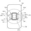
상기 무선 충전 패드 202는 송신 코일 201, 송신 코일 201의 외곽에 배치된 적어도 하나의 패드 자성체 291, 상기 송신 코일 201과 패드 자성체 291을 감싸는 패드 케이스 204를 포함할 수 있다. 추가적으로, 상기 무선 충전 패드 202는 상기 충전 케이블과 연결되어 상기 콘센트로부터 공급된 전원을 상기 송신 코일 201에 공급하는 송신 전원 회로를 더 포함할 수 있다.The
상기 무선 충전 패드 202의 패드 케이스 204는 예컨대 원형 또는 다각형(예: 사각형) 등으로 형성될 수 있다. 패드 케이스 204의 지름은 전자 장치 100의 단축 길이보다 크게 형성될 수 있다. 그러나, 다양한 실시 예들이 이에 한정되는 것은 아니며, 패드 케이스 204 지름은 단축 길이보다도 작게 형성될 수도 있다.The
상기 송신 코일 201은 패드 케이스 204 중앙부 내측에 하나의 코일이 감겨져 배치될 수 있다. 상기 일정 두께를 가지는 송신 코일 201은 감겨지는 동안 일정 면을 형성할 수 있다. 상기 송신 코일 201은 예컨대 중앙부가 빈 환형으로 마련될 수 있다. 상기 송신 코일 201은 예컨대 전자 장치 100에 배치된 수신 코일 181에 비하여 상대적으로 지정된 크기만큼 크게 형성될 수 있다. 또는, 상기 송신 코일 201은 상기 수신 코일 181과 실질적으로 유사한 크기나 형상을 가질 수 있다.The transmitting
상기 패드 자성체 291은 송신 코일 201에 인접된 영역에 배치될 수 있다. 다양한 실시 예에 따르면, 상기 패드 자성체 291은 예컨대, 지정된 크기 이상의 자력을 가진 자석일 수 있다. 상기 패드 자성체 291은 예컨대, 강자성체, 준강자성체, 반강자성체일 수 있다.The pad
상기 패드 자성체 291은 송신 코일 201의 외곽 일정 지점에 적어도 하나가 배치될 수 있다. 예컨대, 패드 자성체 291은 복수의 패드 서브 자성체들 291a, 291b, 291c, 291d을 포함할 수 있다. 한 실시 예에 따르면, 복수개의 패드 서브 자성체들 291a, 291b, 291c, 291d은 송신 코일 201의 중심점을 기준으로 상호 대칭되도록 배치될 수 있다. 도시된 도면을 참조하면, 패드 서브 자성체들 291a, 291b, 291c, 291d은 제1 패드 서브 자성체 291a, 제2 패드 서브 자성체 291b, 제3 패드 서브 자성체 291c, 제4 패드 서브 자성체 291d를 포함할 수 있다. 상기 제1 패드 서브 자성체 291a는 예컨대, 제3 패드 서브 자성체 291c와 송신 코일 201의 중심점(또는 원점)을 기준으로 상호 대칭되는 위치에 배치될 수 있다. 상기 제2 패드 서브 자성체 291b는 예컨대, 제4 패드 서브 자성체 291d와 송신 코일 201의 중심점(또는 원점)을 기준으로 상호 대칭되는 위치에 배치될 수 있다.At least one pad
상기 제1 패드 서브 자성체 291a와 제2 패드 서브 자성체 291b 사이의 제1 간격은 상기 제1 패드 서브 자성체 291a와 제3 패드 서브 자성체 291c 사이의 제2 간격과 유사 또는 실질적으로 동일할 수 있다. 또한 상기 제4 패드 서브 자성체 291d와 제2 패드 서브 자성체 291b 사이의 제3 간격은 상기 제4 패드 서브 자성체 291d와 제3 패드 서브 자성체 291c 사이의 제4 간격과 유사 또는 실질적으로 동일할 수 있다. 상술한 설명에서는 상기 패드 서브 자성체가 4개가 배치된 상태를 예시하였으나, 다양한 실시 예들이 이에 한정되는 것은 아니다. 예컨대, 상기 패드 서브 자성체는 2개, 3개, 5개, 6개, 8개 등 다양한 개수로 마련될 수 있다.A first gap between the first pad sub
다양한 실시 예에 따르면, 상기 패드 자성체 291은 일정 길이를 가진 막대 형태로 마련될 수도 있다. 예컨대, 상기 패드 자성체 291은 제1 패드 서브 자성체 291a 지점과 제2 패드 서브 자성체 291b 지점을 잇는 막대 형태의 자성체를 포함하고, 제3 패드 서브 자성체 291c 지점과 제4 패드 서브 자성체 291d 지점을 잇는 막대 형태의 자성체를 포함할 수 있다. 또한, 상기 패드 자성체 291은 제1 패드 서브 자성체 291a 지점과 제3 패드 서브 자성체 291c 지점을 잇는 막대 형태의 자성체를 포함하고, 제2 패드 서브 자성체 291b 지점과 제4 패드 서브 자성체 291d 지점을 잇는 막대 형태의 자성체를 포함할 수 있다. 이에 따라, 상기 패드 자성체 291은 예컨대 막대 형태의 자성체들이 송신 코일 201의 중앙을 기준으로 상호 대칭되는 위치에 배치될 수 있다. 또는 패드 자성체 291은 상기 막대 형태의 자성체들이 연결된 띠 형상을 가질 수도 있다.According to various embodiments, the
상기 패드 서브 자성체들 291a, 291b, 291c, 291d은 동일면에 배치될 수 있다. 예컨대, 상기 패드 서브 자성체들 291a, 291b, 291c, 291d은 송신 코일 201이 배치된 기판의 일정 영역 또는 상기 패드 케이스 204의 내측면, 상기 패드 케이스 204의 표면 등에 배치될 수 있다. 다양한 실시 예에 따르면, 상기 패드 서브 자성체들 291a, 291b, 291c, 291d의 적어도 일부는 다른 면에 위치할 수 있다. 예컨대, 상기 패드 서브 자성체들 291a, 291b, 291c, 291d의 일부는 패드 케이스 204 내부에 배치되고, 나머지 일부는 패드 케이스 204 외부에 배치될 수 있다.The pad sub
상기 전자 장치 100은 디스플레이가 배치되고, 디스플레이를 감싸는 장치 케이스 104를 포함할 수 있다. 상기 전자 장치 100은 장치 케이스 내측에 수신 코일 181 및 장치 자성체 191을 포함할 수 있다. 추가적으로 상기 전자 장치 100은 상기 수신 코일 181과 연결되어 배터리를 충전하는 무선 충전 모듈 등을 더 포함할 수 있다.The
한 실시 예에 따르면, 상기 전자 장치 100은 예컨대, 일측이 타측보다 긴 길이를 가지는 직사각형 형태로 마련될 수 있다. 그러나, 상기 전자 장치 100의 형태는 상술한 형태로 한정되는 것은 아니다. 예컨대, 상기 전자 장치 100은 일측과 타측이 동일한 길이를 가질 수도 있다. 또한, 상기 전자 장치 100은 적어도 일부에 곡면 영역을 포함할 수 있다. 예컨대, 상기 전자 장치 100은 양측면 중 적어도 한 부분이 바깥쪽 방향으로 구부러진 형상(예: 곡면 영역)을 포함할 수 있다.According to an embodiment, the
상기 수신 코일 181은 송신 코일 201에 흐르는 전원에 유도된 전류를 수집하여 무선 충전 모듈에 전달할 수 있다. 상기 수신 코일 181은 예컨대, 전자 장치 100의 중심부에 배치될 수 있다. 상기 수신 코일 181은 일정 두께의 전도성 라인이 일정하게 감겨져 마련될 수 있다. 한 실시 예에 따르면, 상기 수신 코일 181은 중앙에 일정 크기의 공동이 마련되고, 감겨진 횟수에 따라 일정 폭의 면을 가질 수 있다. 전자 장치 100의 기구적 형태 및 수신 코일 181이 배치되는 위치의 제한적 공간에 대응하여 수신 코일 181은 도시된 바와 같이 중앙이 빈 사각띠 형상일 수 있다. 여기서 다양한 실시 예들이 상기 수신 코일 181의 형상에 한정되는 것은 아니다. 예컨대, 상기 수신 코일 181은 송신 코일 201에 대응되는 형태일 수 있다. 또는 상기 수신 코일 181은 상기 송신 코일 201과 실질적으로 유사하거나 동일한 형상일 수 있다. 상기 수신 코일 181은 예컨대, 전자 장치 100의 장치 케이스 104 배면 내측에 배치될 수 있다.The receiving
상기 장치 자성체 191은 상기 수신 코일 181에 인접된 영역에 배치될 수 있다. 상기 장치 자성체 191은 예컨대, 수신 코일 181의 외곽부 일정 영역에 적어도 하나가 배치될 수 있다. 도시된 도면은 장치 자성체 191이 4개의 장치 서브 자성체들 191a, 191b, 191c, 191d을 포함하는 형태를 예시한 것이다. 4개의 장치 서브 자성체들 191a, 191b, 191c, 191d은 예컨대, 제1 장치 서브 자성체 191a, 제2 장치 서브 자성체 191b, 제3 장치 서브 자성체 191c, 제4 장치 서브 자성체 191d를 포함할 수 있다. 상기 제1 장치 서브 자성체 191a 및 제2 장치 서브 자성체 191b 사이의 간격은 상기 제1 패드 서브 자성체 291a 및 제2 패드 서브 자성체 291b 사이의 간격과 실질적으로 동일한(또는 유사한) 간격을 가질 수 있다. 또한, 상기 제3 장치 서브 자성체 191c 및 제4 장치 서브 자성체 191d 사이의 간격은 상기 제3 패드 서브 자성체 291c 및 제4 패드 서브 자성체 291d 사이의 간격과 실질적으로 동일한(또는 유사한) 간격을 가질 수 있다. 또한 상기 제1 장치 서브 자성체 191a 및 제3 장치 서브 자성체 191c 사이의 간격은 상기 제1 패드 서브 자성체 291a 및 제3 패드 서브 자성체 291c 사이의 간격과 실질적으로 동일한(또는 유사한) 간격을 가질 수 있다. 상술한 바와 같이, 상기 장치 서브 자성체들 191a, 191b, 191c, 191d의 위치는 상기 패드 서브 자성체들 291a, 291b, 291c, 291d의 위치에 대응될 수 있다.The device
다양한 실시 예에 따르면, 상기 장치 자성체 191은 상기 패드 자성체 291과 동일 또는 유사한 형상으로 마련될 수 있다. 예컨대, 앞서 언급한 바와 같이, 상기 패드 자성체 291이 막대 형태의 자성체들이 원점을 중심으로 지정된 간격을 가지며 대칭되도록 마련되는 경우, 상기 장치 자성체 191들 역시 막대 형태의 자성체들이 지정된 간격을 가지며 대칭되도록 마련될 수 있다. 상기 장치 자성체 191은 예컨대 자력에 대응하여 인력을 발휘할 수 있는 물질로 마련될 수 있다. 예컨대, 상기 장치 자성체 191은 철판이나, 구리, 알루미늄 등의 금속 판일 수 있다. 또는 상기 장치 자성체 191은 강자성체로 마련될 수 있다. 이 경우, 상기 장치 자성체 191은 상기 패드 자성체 291과 인력을 일으킬 수 있도록, 패드 자성체 291의 극성과 상반된 극성이 패드 자성체 291 방향으로 배치되도록 마련될 수 있다.According to various embodiments, the device
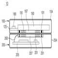
도 2는 한 실시 예에 따른 무선 충전과 관련한 장치 자성체가 수신 코일 기판 일측에 배치된 전자 장치를 포함한 무선 충전 시스템의 일부 구성을 나타낸 도면이다. 상기 도 2는 상기 도 1의 A-A` 단선을 기준으로 하는 단면일 수 있다. 이러한 도면은 다양한 실시 예들에서 명쾌한 설명을 위하여 전자 장치 100 및 무선 충전 장치 200의 일부 구성만을 단순화하여 도시한 것이다.2 is a diagram illustrating a partial configuration of a wireless charging system including an electronic device in which a device magnetic material related to wireless charging is disposed on one side of a receiving coil substrate according to an embodiment. 2 may be a cross-section based on the line A-A′ of FIG. 1 . These drawings illustrate only some configurations of the
도 2를 참조하면, 전자 장치 100은 장치 케이스 104, 장치 케이스 104 내측에 배치된 수신 코일 기판 187, 수신 코일 기판 187 상에(또는 내측에) 배치된 수신 코일 181, 수신 코일 기판 187 상에(또는 내측에) 배치된 장치 자성체 191, 상기 수신 코일 기판 187 상부에 배치된 배터리 190, 배터리 190 일측에 배치된 장치 인쇄회로기판 125, 무선 충전 모듈 180을 포함할 수 있다.Referring to FIG. 2 , the
상기 장치 케이스 104는 예컨대, 일측에 디스플레이가 노출되도록, 디스플레이의 외곽을 감싸는 형태로 마련될 수 있다. 상기 장치 케이스 104는 배터리 190 삽입 형태(예: 내장형 또는 탈착형)에 따라 탈착형 배터리 커버를 가지거나 또는 일체형으로 마련될 수 있다. 상기 장치 케이스 104 중 무선 충전 장치 200과 대면되는 면은 배면에 해당할 수 있다. 상기 장치 케이스 104의 배면 내측에는 수신 코일 기판 187과 수신 코일 181이 배치되고, 그 상부에 배터리 190이 배치될 수 있다. 도시된 도면에서는 장치 케이스 104를 하나의 통형으로 예시하였으나 다양한 실시 예들에서의 전자 장치 100이 이에 한정되는 것은 아니다. 예컨대, 상기 장치 케이스 104는 디스플레이 쪽을 지지하는 프론트 케이스, 프론트 케이스를 지지하며 배터리 190이 안착되는 영역을 포함하는 리어 케이스, 리어 케이스를 덮는 배터리 케이스 등으로 분리될 수 있다. 또는 상기 장치 케이스 104는 상술한 프론트 케이스, 리어 케이스 또는 배터리 케이스 중 적어도 하나가 일체로 된 형태를 취할 수 있다.The
상기 수신 코일 기판 187은 상기 수신 코일 181이 놓이는 기판일 수 있다. 이러한 수신 코일 기판 187은 예컨대, 수신 코일 181을 지지할 수 있는 일정 강성을 가지는 형태로, 플라스틱 기판이나, 나무 기판 등 다양한 비전도성 재질로 마련될 수 있다. 한 실시 예에 따르면 상기 수신 코일 기판 187은 폴리머 재질 또는 섬유 재질 등으로 마련될 수도 있다. 상기 수신 코일 기판 187 상에 배치되는 상기 수신 코일 181은 예컨대 상기 수신 코일 기판 187 상에 패턴화되어 마련될 수도 있다. 한 실시 예에 따르면, 수신 코일 기판 187은 필름 형태의 박막 기판으로 마련될 수도 있다. 또는 수신 코일 기판 187은 수신 코일 181이 배치될 음각된 영역을 포함할 수 있다. 상기 수신 코일 기판 187 일측에는 장치 자성체 191이 배치될 수 있다. 예컨대, 수신 코일 기판 187 중심부에 수신 코일 181이 배치되고, 수신 코일 181의 외곽부 일정 위치의 수신 코일 기판 187 상에 장치 자성체 191이 배치될 수 있다.The receiving
상기 수신 코일 181은 수신 코일 기판 187 상에(또는 수신 코일 기판 187의 음각된 영역에) 배치될 수 있다. 수신 코일 181은 일정 횟수 이상 감겨져 마련될 수 있다. 이에 따라, 수신 코일 181은 도시된 바와 같이 일정 면을 형성할 수 있다. 수신 코일 181의 중앙부에는 코일이 배치되지 않아 빈 영역을 형성할 수 있다.The receiving
상기 장치 자성체 191은 수신 코일 기판 187 상에(또는 수신 코일 기판 187의 음각된 영역에) 배치되데 상기 수신 코일 181과 나란하게 배치되면서, 수신 코일 기판 187의 가장자리에 배치될 수 있다. 수신 코일 기판 187의 가장자리 영역은 수신 코일 181의 외곽부에 해당할 수 있다.The device
상기 수신 코일 181 및 장치 자성체 191이 배치된 수신 코일 기판 187은 예컨대 장치 케이스 104의 배면 내측에 배치될 수 있다. 또는 상기 수신 코일 기판 187은 배터리 190 표면에 배치되데 상기 장치 케이스 104 쪽 방향에 배치될 수 있다.The receiving
상기 배터리 190은 수신 코일 기판 187과 대면되도록 배치될 수 있다. 한 실시 예에 따르면, 상기 수신 코일 기판 187은 상기 배터리 190의 표면에 배치될 수도 있다. 상기 배터리 190 일측은 장치 인쇄회로기판 125와 연결될 수 있다. 상기 배터리 190은 상기 수신 코일 181에 유도된 전원으로 충전될 수 있다.The
상기 장치 인쇄회로기판 125는 상기 배터리 190 일측과 연결되는 신호 라인을 포함할 수 있다. 또한 상기 장치 인쇄회로기판 125는 상기 수신 코일 181이 연결되는 신호 라인을 포함할 수 있다.The device printed
상기 무선 충전 모듈 180은 상기 장치 인쇄회로기판 125 상에 배치되어, 수신 코일 181에 유도된 전원을 수집할 수 있다. 상기 무선 충전 모듈 180은 수집된 전원을 배터리 190을 충전할 수 있는 형태로 전환한 후 배터리 190에 공급할 수 있다.The
상기 무선 충전 장치 200은 패드 케이스 204, 패드 인쇄회로기판 205, 전원 케이블 260, 송신 코일 기판 207, 송신 코일 201, 패드 자성체 291을 포함할 수 있다.The
상기 패드 케이스 204는 예컨대, 패드 인쇄회로기판 205, 송신 코일 기판 207, 송신 코일 201, 패드 자성체 291 등을 감싸도록 마련될 수 있다. 상기 패드 케이스 204는 예컨대 투명 재질 등으로 마련될 수 있다. 한 실시 예에 따르면, 상기 패드 케이스 204는 적어도 일부가 투명 플라스틱, 아크릴, 유리 등으로 마련될 수 있다. 예컨대, 상기 패드 케이스 204는 상기 송신 코일 201이 배치된 영역을 포함하는 지정된 영역이 투명 재질로 형성될 수 있다. 도시된 도면에서 패드 케이스 204의 크기가 상기 전자 장치 100의 크기와 유사한 형태로 예시하였으나, 다양한 실시 예들이 이에 한정되는 것은 아니다. 예컨대, 상기 패드 케이스 204는 상기 전자 장치 100의 일측 길이보다 큰 지름을 가지도록 마련될 수 있다. 또는 상기 패드 케이스 204는 상기 전자 장치 100의 일측 길이보다 작은 지름을 가지도록 마련될 수 있다.The
상기 패드 인쇄회로기판 205는 전원 케이블 260에 연결되는 신호 라인과, 상기 송신 코일 201에 전원을 공급하는 라인을 포함할 수 있다. 또한 패드 인쇄회로기판 205는 전원 케이블이 공급한 전원을 송신 코일 201을 통해 지정된 주파수로 출력될 수 있도록 처리하는 송신 전원 회로가 배치될 수 있다. 이러한 패드 인쇄회로기판 205는 예컨대 패드 케이스 204 일측에 고정될 수 있다.The pad printed
상기 전원 케이블 260은 상기 패드 인쇄회로기판 205와 상기 송신 코일 201을 연결하는 케이블일 수 있다. 이러한 전원 케이블 260은 예컨대 가연인쇄회로기판(FPCB) 형태로 마련될 수 있다. 또는 전원 케이블 260은 지정된 크기의 연성을 가지는 동축 케이블일 수 있다. 이에 따라, 상기 전원 케이블 260은 상기 송신 코일 기판 207의 움직임에 대응하여 움직일 수 있도록 마련될 수 있다.The
상기 송신 코일 기판 207 상에(또는 음각된 일정 영역에) 예컨대, 송신 코일 201이 배치될 수 있다. 상기 송신 코일 기판 207은 상기 송신 코일 201의 전체 크기보다 큰 영역을 가질 수 있다. 상기 송신 코일 기판 207은 비전도성 재질로 마련될 수 있다. 상기 송신 코일 기판 207은 예컨대 일측이 장치 케이스 104에 탄성적으로 연결될 수 있다. 이에 따라, 송신 코일 기판 207은 외부 압력이나 일정 방향의 자속(flux)을 가진 자력이 형성되면, 해당 방향에 따라 이동할 수 있다. 상기 송신 코일 기판 207은 외부 압력이나 자력이 해제되면 원래의 위치(예: 장치 케이스 104의 중앙부)로 복귀할 수 있다.For example, the transmitting
상기 송신 코일 201은 상기 송신 코일 기판 207 상에(또는 음각된 영역에) 배치될 수 있다. 상기 송신 코일 201은 앞서 설명한 바와 같이 전도성 재질의 라인이 환형으로 감겨져 마련될 수 있다. 이에 따라, 도시된 바와 같이 송신 코일 201은 일정 면을 형성하되, 중심부가 빈 형상으로 마련될 수 있다. 상기 송신 코일 201 일측은 패드 인쇄회로기판 205 상에 배치된 송신 전원 회로에 연결될 수 있다.The transmitting
상기 패드 자성체 291은 상기 송신 코일 기판 207의 일정 위치에(예: 송신 코일 기판 207의 가장자리 상에 또는 가장자리의 음각된 영역에) 배치될 수 있다. 상기 패드 자성체 291은 예컨대 장치 자성체 191과 자력(인력)에 의해 당겨지도록 마련될 수 있다. 이와 관련하여, 패드 자성체 291은 일정 크기 자력을 가지는 영구자석일 수 있다. 이러한 패드 자성체 291은 상기 장치 자성체 191이 배치된 형태와 실질적으로 동일한 형태를 가질 수 있다.The pad
상술한 바와 같이, 한 실시 예에 따른 전자 장치 100의 수신 코일 181은 배터리 190과 장치 케이스 104의 배면 사이에 배치되고, 상기 장치 자성체 191은 수신 코일 181과 나란한 면에 배치될 수 있다.As described above, the receiving
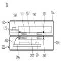
도 3은 한 실시 예에 따른 무선 충전과 관련한 장치 자성체가 장치 케이스 일측에 배치된 전자 장치를 포함한 무선 충전 시스템의 일부 구성을 나타낸 도면이다.3 is a diagram illustrating a partial configuration of a wireless charging system including an electronic device in which a device magnetic body related to wireless charging is disposed on one side of a device case according to an exemplary embodiment.
도 3을 참조하면, 전자 장치 100은 장치 케이스 104, 장치 케이스 104 내측에 배치된 수신 코일 기판 187, 수신 코일 기판 187 상에(또는 내측에) 배치된 수신 코일 181, 장치 케이스 104 일측에 배치된 장치 자성체 191, 상기 수신 코일 기판 187 상부에 배치된 배터리 190, 배터리 190 일측에 배치된 장치 인쇄회로기판 125, 무선 충전 모듈 180을 포함할 수 있다.Referring to FIG. 3 , the
상기 무선 충전 장치 200은 패드 케이스 204, 상기 패드 케이스 204 내측 바닥부에 배치되는 패드 인쇄회로기판 205, 상기 패드 인쇄회로기판 205와 송신 코일 기판 207을 연결하는 전원 케이블 260, 상기 패드 인쇄회로기판 205 상부에 배치되며 상기 패드 인쇄회로기판 205의 신호 라인과 상기 전원 케이블 260을 통하여 연결되는 송신 코일 기판 207, 상기 송신 코일 기판 상에(또는 상기 송신 코일 기판에 형성된 음각된 영역에) 배치되는 송신 코일 201, 상기 송신 코일 기판 상에(또는 상기 송신 코일 기판에 형성된 음각된 영역에) 배치되는 패드 자성체 291을 포함할 수 있다.The
상술한 구성의 무선 충전 시스템 10은 상기 장치 자성체 191이 수신 코일 181이 배치된 면과 다른 영역에 배치될 수 있다. 예컨대, 상술한 바와 같이, 상기 장치 자성체 191은 장치 케이스 104 일측에 배치될 수 있다. 한 실시 예에 따르면, 상기 장치 자성체 191은 장치 케이스 104의 배면 내측에 배치될 수 있다. 또는 상기 장치 자성체 191은 도시된 바와 같이 장치 케이스 104의 배면 전후를 관통하며 배치될 수 있다. 이와 관련하여, 장치 케이스 104는 장치 자성체 191이 배치될 수 있는 적어도 하나의 홀을 포함할 수 있다. 상기 장치 자성체 191은 상기 홀에 삽입 고정될 수 있다. 다양한 실시 예에 따르면, 장치 자성체 191은 장치 케이스 104의 배면 표면에 배치될 수도 있다. 이 경우, 장치 자성체 191은 접착 부재 등을 이용하여 장치 케이스 104 배면 표면에 고정될 수 있다. 장치 케이스 104 일측에 배치되는 장치 자성체 191의 위치는 패드 자성체 291들의 배치 간격에 대응되는 간격을 가질 수 있다.In the
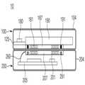
도 4는 한 실시 예에 따른 무선 충전과 관련한 장치 자성체가 배터리 일측에 배치된 전자 장치를 포함한 무선 충전 시스템의 일부 구성을 나타낸 도면이다.4 is a diagram illustrating a partial configuration of a wireless charging system including an electronic device in which a device magnetic material related to wireless charging is disposed on one side of a battery according to an exemplary embodiment.
도 4를 참조하면, 전자 장치 100은 장치 케이스 104, 상기 장치 케이스 104 내측에 배치된 수신 코일 기판 187, 수신 코일 기판 187 상에(또는 기판 내측에) 배치된 수신 코일 181, 배터리 190과 수신 코일 기판 187 사이에 배치된 장치 자성체 191, 상기 수신 코일 기판 187 상부에 배치된 배터리 190, 배터리 190 일측에 배치된 장치 인쇄회로기판 125, 무선 충전 모듈 180을 포함할 수 있다.Referring to FIG. 4 , the
상기 무선 충전 장치 200은 패드 케이스 204, 상기 패드 케이스 204 내측 바닥부에 배치되는 패드 인쇄회로기판 205, 상기 패드 인쇄회로기판 205와 상기 송신 코일 기판 207을 연결하는 전원 케이블 260, 상기 패드 인쇄회로기판 205 상부에 배치되며 상기 패드 인쇄회로기판 205의 신호 라인과 상기 전원 케이블 260을 통해 연결되는 송신 코일 기판 207, 상기 송신 코일 기판 상에(또는 상기 송신 코일 기판에 형성된 음각된 영역에) 배치되는 송신 코일 201, 상기 송신 코일 기판 207 상에(또는 상기 송신 코일 기판 207에 형성된 음각된 영역에) 배치되는 패드 자성체 291을 포함할 수 있다. 상기 패드 자성체 291은 예컨대, 송신 코일 기판 207 가장자리 또는 송신 코일 201 외곽부에 적어도 하나가 배치될 수 있다.The
상술한 무선 충전 시스템 10은 상기 장치 자성체 191이 배터리 190 및 수신 코일 기판 187 사이에 배치되는 경우를 예시한 것이다. 한 실시 예에 따르면, 상기 장치 자성체 191은 상기 배터리 190의 표면 일측에 배치될 수 있다. 이와 관련하여, 상기 장치 자성체 191은 자성체 역할을 하는 바디와 상기 배터리 190 일측에 고정되기 위한 접착 부재를 포함할 수 있다. 상기 배터리 190은 예컨대 상기 장치 자성체 191이 고정될 수 있도록 표면에 적어도 하나의 홈이 마련될 수 있다.The aforementioned
다양한 실시 예에 따르면, 상기 장치 자성체 191은 상기 수신 코일 기판 187의 상부면(예: 배터리 190을 바라보는 면)에 배치될 수도 있다. 또는 상기 수신 코일 기판 187 및 상기 배터리 190에 각각 상기 장치 자성체 191이 삽입될 수 있는 형태의 홈이 마련될 수 있다. 이에 따라, 상기 장치 자성체 191은 수신 코일 기판 187의 상부면과 상기 배터리 190의 하부면 사이에 배치될 수 있다. 상기 장치 자성체 191이 배치된 위치는 수직한 방향으로 무선 충전 장치 200에 배치된 패드 자성체 291과 정렬되는 위치일 수 있다. 이와 관련하여, 장치 자성체 191의 배치 간격은 상기 패드 자성체 291의 배치 간격과 실질적으로 동일 또는 유사한 형태를 가질 수 있다. 또한, 상기 장치 자성체 191의 크기 또는 모양은 상기 패드 자성체 291의 크기 또는 모양과 실질적으로 동일 또는 유사할 수 있다.According to various embodiments, the device
도 5는 한 실시 예에 따른 무선 충전과 관련한 패드 자성체가 패드 케이스 일측에 배치된 무선 충전 장치를 포함한 무선 충전 시스템의 일부 구성을 나타낸 도면이다.5 is a diagram illustrating a partial configuration of a wireless charging system including a wireless charging device in which a pad magnetic material related to wireless charging is disposed on one side of a pad case according to an embodiment.
도 5를 참조하면, 전자 장치 100은 장치 케이스 104, 장치 케이스 104 내측에 배치된 수신 코일 기판 187, 수신 코일 기판 187 상에(또는 내측에) 배치된 수신 코일 181, 상기 수신 코일 기판 일측(예: 상기 수신 코일 기판 187 내측 또는 상기 수신 코일 기판 187의 음각된 일정 영역)에 배치된 장치 자성체 191, 상기 수신 코일 기판 187 상부에 배치된 배터리 190, 배터리 190 일측에 배치된 장치 인쇄회로기판 125, 무선 충전 모듈 180을 포함할 수 있다.Referring to FIG. 5 , the
상기 무선 충전 장치 200은 패드 케이스 204, 상기 패드 케이스 204 내측 바닥부에 배치되는 패드 인쇄회로기판 205, 상기 패드 인쇄회로기판 205와 상기 송신 코일 기판 207을 연결하는 전원 케이블 260, 상기 패드 인쇄회로기판 205 상부에 배치되며 상기 패드 인쇄회로기판 205의 신호 라인과 상기 전원 케이블 260을 통해 연결되는 송신 코일 기판 207, 상기 송신 코일 기판 상에(또는 상기 송신 코일 기판에 형성된 음각된 영역에) 배치되는 송신 코일 201, 상기 송신 코일 기판 207 하부에(또는 상기 송신 코일 기판 207 하부로 적어도 일부가 노출되도록) 배치되는 패드 자성체 291을 포함할 수 있다.The
상술한 무선 충전 시스템 10은 상기 패드 자성체 291이 상기 송신 코일 기판 207 하부 일측에 배치되는 경우를 예시한 것이다. 한 실시 예에 따르면, 상기 패드 자성체 291은 상기 송신 코일 기판 207 하부면에 배치될 수 있다. 이와 관련하여, 상기 송신 코일 기판 207의 하부면(예: 전자 장치 100을 바라보는 면과 반대되는 면)에는 상기 패드 자성체 291이 배치될 수 있는 적어도 하나의 홈이 마련될 수 있다. 상기 패드 자성체 291은 상기 송신 코일 기판 207 하부에 배치되면서, 상기 송신 코일 기판 207의 표면보다 돌출되도록 배치될 수 있다.The above-described
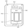
도 6은 한 실시 예에 따른 배터리 상에 장치 자성체가 배치된 전자 장치의 한 예를 나타낸 도면이다.6 is a diagram illustrating an example of an electronic device in which a device magnetic material is disposed on a battery according to an exemplary embodiment.
도 6은 참조하면, 도시된 전자 장치 100의 일부 구성은 예컨대, 배터리 190 영역이 형성된 리어 커버 162가 노출된 형태를 예시한 것이다. 상기 배터리 190의 적어도 일부에는 다양한 실시 예에서 언급한 수신 코일 181 및 장치 자성체 191이 배치될 수 있다. 예컨대, 상기 배터리 190 표면 일측에 중심부가 빈 수신 코일 181이 배치될 수 있다. 상기 장치 자성체 191은 상기 배터리 190 상에 배치되데 상기 수신 코일 181의 외곽부에 배치될 수 있다. 상기 장치 자성체 191의 배치 간격은 앞서 설명한 패드 자성체 291의 배치 간격과 실질적으로 동일 또는 유사할 수 있다. 다양한 실시 예에 따르면, 상기 리어 커버 162 상부에는 배터리 커버 등이 배치되어 상기 리어 커버 162 면을 덮을 수 있다. 추가적으로, 상기 전자 장치 100은 카메라 163 등의 구성을 더 포함할 수 있다.Referring to FIG. 6 , a partial configuration of the illustrated
도 7은 한 실시 예에 따른 전자 장치의 프레임 상에 장치 자성체가 배치된 한 예를 나타낸 도면이다.7 is a diagram illustrating an example in which a device magnetic material is disposed on a frame of an electronic device according to an exemplary embodiment.
도 7은 참조하면, 도시된 전자 장치 100의 일부 구성은 전자 장치의 프레임(예: 리어 커버 162 또는 안착 커버 165)가 노출된 형태로서, 예컨대, 배터리가 배치된 영역이 폐구된 리어 커버 162가 노출된 형태를 예시한 것이다. 다양한 실시 예에 따르면, 전자 장치 100은 배터리 190 내장형으로 마련될 수 있다. 이와 관련하여, 전자 장치 100은 배터리 190이 안착된 배터리 안착부를 덮는 안착 커버 165를 포함할 수 있다. 상기 안착 커버 165는 리어 커버 162와 동일한 면에 배치될 수 있다. 한 실시 예에 따르면, 상기 안착 커버 165의 적어도 일부에는 다양한 실시 예에서 언급한 수신 코일 181 및 장치 자성체 191이 배치될 수 있다. 예컨대, 상기 안착 커버 165 표면 일측에 수신 코일 181이 배치될 수 있다. 상기 장치 자성체 191은 상기 안착 커버 165 상에 배치되데 상기 수신 코일 181의 외곽부에 배치될 수 있다. 상기 장치 자성체 191의 배치 간격은 앞서 설명한 패드 자성체 291의 배치 간격과 실질적으로 동일 또는 유사할 수 있다. 다양한 실시 예에 따르면, 상기 리어 커버 162 및 상기 안착 커버 165 상부에는 배터리 커버가 배치되어 상기 리어 커버 162 및 상기 안착 커버 165를 덮을 수 있다. 추가적으로, 상기 전자 장치 100은 카메라 163 등의 구성을 더 포함할 수 있다.Referring to FIG. 7 , some components of the illustrated
도 8은 한 실시 예에 따른 배면(Back or Battery) 커버 상에 장치 자성체가 배치된 전자 장치의 한 예를 나타낸 도면이다.8 is a diagram illustrating an example of an electronic device in which a device magnetic body is disposed on a back or battery cover according to an embodiment.
도 8은 참조하면, 다양한 실시 예에 따르면, 전자 장치 100은 배면 커버 167을 포함할 수 있다. 또는 상기 전자 장치 100은 배터리 내장형으로 마련된 경우, 전면에 배치된 디스플레이의 외곽을 감싸는 케이스가 배면 커버 167이 일체형으로 마련될 수 있다.Referring to FIG. 8 , according to various embodiments, the
한 실시 예에 따르면, 상기 배면 커버 167 일측에는 수신 코일 181 및 장치 자성체 191이 배치될 수 있다. 예컨대, 상기 배면 커버 167의 내측에는 수신 코일 181이 배치될 수 있다. 또한, 상기 장치 자성체 191의 적어도 일부는 상기 배면 커버 167의 외부 표면에 배치될 수 있다. 다양한 실시 예에 따르면, 상기 수신 코일 181의 적어도 일부가 배면 커버 167의 표면에 노출되도록 배치될 수도 있다. 또한 상기 상기 장치 자성체 191은 상기 배면 커버 167의 내측에 배치되어 외부로 노출되지 않을 수 있다. 또는 다양한 실시 예에 따르면, 상기 수신 코일 181 및 상기 장치 자성체 191은 상기 배면 커버 167의 내측에 배치될 수 있다. 또는 상기 수신 코일 181 및 상기 장치 자성체 191은 상기 배면 커버 167의 외부 표면에 배치될 수 있다. 상기 장치 자성체 191은 상기 수신 코일 181의 외곽에 위치할 수 있다.According to an embodiment, the receiving
한편, 상술한 도 6 내지 도 8 설명에서는 수신 코일 181이 우측에 일정 부분 치우쳐 배치된 형상을 예시하였으나, 다양한 실시 예들이 이에 한정되는 것은 아니다. 예컨대, 상기 수신 코일 181은 전자 장치 100의 중심을 기준으로 일정 영역 내에 배치될 수도 있다. 추가적으로, 상기 전자 장치 100은 카메라 163 등의 구성을 더 포함할 수 있다.Meanwhile, in the description of FIGS. 6 to 8 , a shape in which the receiving
상술한 다양한 실시 예에 따르면, 한 실시 예에 따른 전자 장치는 무선 충전과 관련하여 코일이 감겨져 면을 형성하되 중앙이 빈 수신 코일, 상기 수신 코일의 중심부로 일정 거리 이격된 위치에 배치되는 장치 자성체, 상기 수신 코일에 유도된 전원을 수집하는 무선 충전 모듈을 포함할 수 있다.According to the above-described various embodiments, in the electronic device according to an embodiment, a coil is wound to form a surface in connection with wireless charging, but a receiving coil having an empty center, a device magnetic material disposed at a location spaced apart from the center of the receiving coil by a predetermined distance , It may include a wireless charging module for collecting the power induced in the receiving coil.
다양한 실시 예에 따르면, 상기 전자 장치는 상기 무선 충전 모듈과 연결되어 상기 전원에 의해 충전되며, 일측 표면에 상기 수신 코일이 배치되는 배터리를 더 포함할 수 있다.According to various embodiments of the present disclosure, the electronic device may further include a battery connected to the wireless charging module to be charged by the power, and the receiving coil disposed on one surface.
다양한 실시 예에 따르면, 상기 장치 자성체는 상기 수신 코일이 형성된 상기 배터리 표면 일측에 배치될 수 있다.According to various embodiments, the device magnetic body may be disposed on one side of the battery surface on which the receiving coil is formed.
다양한 실시 예에 따르면, 상기 전자 장치는 상기 배터리가 안착되는 안착부를 덮도록 배치되며, 상기 수신 코일이 배치되는 안착 커버를 더 포함할 수 있다.According to various embodiments of the present disclosure, the electronic device may further include a seating cover disposed to cover the seating portion on which the battery is mounted, and on which the receiving coil is disposed.
다양한 실시 예에 따르면, 상기 장치 자성체는 상기 수신 코일이 형성된 상기 안착 커버 표면 일측에 배치될 수 있다.According to various embodiments, the device magnetic body may be disposed on one side of the seating cover surface on which the receiving coil is formed.
다양한 실시 예에 따르면, 상기 전자 장치는 상기 배터리가 배치된 배면을 덮도록 배치되며, 상기 수신 코일 또는 상기 장치 자성체 중 적어도 하나가 일측에 배치되는 배면 커버(예: 배터리 커버 또는 전자 장치의 외곽을 형성하는 케이스 부분 중 배면에 위치한 영역)를 더 포함할 수 있다.According to various embodiments of the present disclosure, the electronic device is disposed to cover a rear surface on which the battery is disposed, and at least one of the receiving coil or the device magnetic material is disposed on one side of a rear cover (eg, a battery cover or the outside of the electronic device). It may further include a region (located on the rear side of the case portion to be formed).
다양한 실시 예에 따르면, 상기 수신 코일 및 상기 장치 자성체 중 적어도 하나는 상기 배면 커버 내측 또는 상기 배면 커버 외측 중 적어도 하나에 배치될 수 있다.According to various embodiments, at least one of the receiving coil and the device magnetic body may be disposed on at least one of an inner side of the rear cover or an outer side of the rear cover.
다양한 실시 예에 따르면, 상기 전자 장치는 상기 수신 코일이 배치되는 수신 코일 기판을 더 포함할 수 있다.According to various embodiments, the electronic device may further include a receiving coil substrate on which the receiving coil is disposed.
다양한 실시 예에 따르면, 상기 장치 자성체는 수신 코일 기판 일측에 배치될 수 있다.According to various embodiments, the device magnetic material may be disposed on one side of the receiving coil substrate.
다양한 실시 예에 따르면, 상기 장치 자성체는 상기 수신 코일의 외곽에 복수개가 배치되는 장치 서브 자성체를 포함할 수 있다.According to various embodiments, the device magnetic body may include a plurality of device sub-magnetic bodies disposed outside the receiving coil.
다양한 실시 예에 따르면, 상기 장치 서브 자성체는 상기 수신 코일의 중심점을 기준으로 대칭되도록 배치될 수 있다.According to various embodiments, the device sub-magnetic material may be disposed to be symmetrical with respect to a center point of the receiving coil.
다양한 실시 예에 따르면, 상기 장치 자성체는 무선 충전 장치에 배치되는 패드 자성체의 배치 형태와 실질적으로 동일하게 형성될 수 있다.According to various embodiments, the device magnetic body may be formed to be substantially the same as the arrangement shape of the pad magnetic body disposed in the wireless charging device.
도 9는 한 실시 예에 따른 무선 충전 패드의 한 예에 대응하는 분해 사시도이다.9 is an exploded perspective view corresponding to an example of a wireless charging pad according to an embodiment.
도 9를 참조하면, 한 실시 예에 따른 무선 충전 패드 202는 상부 케이스 21, 하부 케이스 22, 지지 구조물 예컨대, 베어링 모듈 23을 포함할 수 있다. 또한, 상기 무선 충전 패드 202는 송신 코일 기판 207, 송신 코일 201, 패드 자성체 291, 전원 케이블 260 및 패드 인쇄회로기판 205를 포함할 수 있다.Referring to FIG. 9 , the
상기 상부 케이스 21은 예컨대, 원형 또는 타원형의 형상으로 하부 케이스 22를 덮는 덮개 형태로 마련될 수 있다. 상기 상부 케이스 21은 예컨대 적어도 일부가 투명하게 형성되거나, 투명 재질로 마련될 수 있다. 한 실시 예에 따르면, 상기 상부 케이스 21은 상기 송신 코일 201이 기본적으로 배치되는 위치(예: 하부 케이스 22의 중심 일정 영역)의 일정 영역에 대응하는 영역이 투명하게 마련될 수 있다. 상기 상부 케이스 21의 전면은 평평하게 형성될 수도 있으나, 중심부로 갈수록 지정된 크기만큼 깊어지거나, 내측으로 함몰된 형상을 가질 수도 있다.The
상기 하부 케이스 22는 내측에 베어링 모듈 23 및 송신 코일 기판 207 등이 배치될 수 있도록 내측에 빈 영역이 마련될 수 있다. 상기 하부 케이스 22 상부는 개구될 수 있다. 상기 하부 케이스 22의 개구된 영역은 상기 상부 케이스 21 결합에 의해 가려질 수 있다. 상기 하부 케이스 22 내측에는 베어링 모듈 23이 배치될 수 있다. 상기 상부 케이스 21이 결합된 상기 하부 케이스 22는 상기 베어링 모듈 23 상에 배치된 송신 코일 기판 207이 일정 방향으로 이동될 수 있도록 상측에 일정 빈 공간을 형성할 수 있다. 상기 하부 케이스 22 일측에는 상기 패드 인쇄회로기판 205가 배치될 수 있다. 상기 하부 케이스 22는 상기 패드 인쇄회로기판 205와 충전 케이블이 연결될 수 있도록 충전 케이블이 관통하는 연결구를 포함할 수 있다.An empty area may be provided inside the
상기 베어링 모듈 23은 상기 하부 케이스 22 내측에 배치될 수 있다. 상기 베어링 모듈 23 상부에 송신 코일 기판 207이 배치될 수 있다. 상기 베어링 모듈 23은 상기 송신 코일 기판 207이 일정 방향으로 쉽게 이동될 수 있도록 지원할 수 있다. 상기 베어링 모듈 23은 상기 송신 코일 기판 207의 후면을 지지하는 복수개의 베어링을 포함할 수 있다. 상기 베어링은 예컨대 금속 또는 비금속(예: 세라믹) 등 다양한 재질로 마련될 수 있다.The bearing
상기 송신 코일 기판 207은 상기 베어링 모듈 23 상부에 배치될 수 있다. 상기 송신 코일 기판 207의 중심부에는 송신 코일 201이 배치될 수 있다. 상기 송신 코일 기판 207의 외곽부(또는 상기 송신 코일 201의 외곽부)에는 패드 자성체 291이 배치될 수 있다. 이에 따라, 상부 케이스 21 상에 상기 패드 자성체 291과 대응하는 물체가 접근하는 경우 상기 송신 코일 기판 207은 상기 물체 접근에 따라 이동될 수 있다.The transmitting
상기 전원 케이블 260은 연성 재료로 마련되어, 상기 송신 코일 기판 207의 움직임에 대응하여 휘어지거나 구부러질 수 있다. 상기 전원 케이블 260은 패드 인쇄회로기판 205와 상기 송신 코일 201을 연결하여, 패드 인쇄회로기판 205가 제공하는 전원을 송신 코일 201에 전달할 수 있다. 상기 전원 케이블 260은 좌우, 전후 등으로 휘어지거나 구부러질 수 있다.The
도 10은 한 실시 예에 따른 무선 충전 패드의 다른 예에 대응하는 분해 사시도이다.10 is an exploded perspective view corresponding to another example of a wireless charging pad according to an embodiment.
도 10을 참조하면, 상기 무선 충전 패드 202는 상부 케이스 21, 하부 케이스 22, 지지 구조물 예컨대 탄성 구조물 24를 포함할 수 있다. 또한, 상기 무선 충전 패드 202는 송신 코일 기판 207, 송신 코일 201, 패드 자성체 291, 전원 케이블 260 및 패드 인쇄회로기판 205를 포함할 수 있다.Referring to FIG. 10 , the
상기 상부 케이스 21은 앞서 도 9에서 설명한 상부 케이스 21과 실질적으로 동일 또는 유사한 형태일 수 있다. 한 실시 예에 따르면, 상기 상부 케이스 21은 원형 또는 타원형뿐만 아니라 다각형의 형상으로 하부 케이스 22를 덮는 덮개 형태로 마련될 수 있다. 상기 상부 케이스 21은 예컨대 적어도 일부가 투명하게 형성되거나, 투명 재질(예: 투명 플라스틱, 유리 등)로 마련될 수 있다.The
상기 하부 케이스 22는 내측에 송신 코일 기판 207 및 송신 코일 기판 207을 이동 가능하도록 지지하는 탄성 구조물 24를 포함할 수 있다. 상기 하부 케이스 22는 상기 탄성 구조물 24의 일측이 고정될 수 있도록 측벽이 일정 높이만큼 형성되는 구조를 가질 수 있다. 상기 하부 케이스 22 일측에는 상기 패드 인쇄회로기판 205가 배치될 수 있다. 상기 하부 케이스 22는 상기 패드 인쇄회로기판 205와 충전 케이블이 연결될 수 있도록 충전 케이블이 관통하는 연결구를 포함할 수 있다. 도시된 도면에서는 하부 케이스 22 일측에 패드 인쇄회로기판 205가 배치되기 위한 돌출된 형태를 예시하였으나, 다양한 실시 예들이 이에 한정되는 것은 아니다. 예컨대, 상기 패드 인쇄회로기판 205는 상기 송신 코일 기판 207 하부에 배치될 수 있다. 이에 따라, 상기 하부 케이스 22는 별도의 돌출된 구조 없이 둘레가 둥근 형태로 마련될 수 있다.The
상기 전원 케이블 260은 연성 재료로 마련되어, 상기 송신 코일 기판 207의 움직임에 대응하여 휘어지거나 구부러질 수 있다. 상기 전원 케이블 260은 패드 인쇄회로기판 205와 상기 송신 코일 201을 연결하여, 패드 인쇄회로기판 205가 제공하는 전원을 송신 코일 201에 전달할 수 있다. 상기 전원 케이블 260은 좌우, 전후 등으로 휘어지거나 구부러질 수 있다.The
상기 탄성 구조물 24는 일측이 송신 코일 기판 207과 연결되고, 타측이 하부 케이스 22 측벽과 연결될 수 있다. 이러한 탄성 구조물 24는 예컨대 복수개의 탄성체들 24a, 24b, 24c을 포함할 수 있다. 도시된 도면에서는 3개의 탄성체들 24a, 24b, 24c이 배치된 형태를 예시한 것이다. 각각의 탄성체들 24a, 24b, 24c의 일측은 송신 코일 기판 207의 측면과 연결되고, 타측은 하부 케이스 22 측벽에 고정될 수 있다. 한 실시 예에 따르면, 상기 탄성체들 24a, 24b, 24c은 상기 송신 코일 기판 207이 전후 방향으로 이동 가능하도록 지지할 수 있다. 이에 따라, 상부 케이스 21 상에 상기 패드 자성체 291과 관련된 물체(예: 패드 자성체 291과 인력을 형성하는 물체)가 접근하는 경우, 송신 코일 기판 207이 해당 물체쪽으로 이동 가능하도록 지지할 수 있다. 상기 탄성체들 24a, 24b, 24c은 상기 물체가 일정 거리 이상 이격되는 경우, 상기 송신 코일 기판 207이 원래의 위치(예: 하부 케이스 22의 중심부)로 복귀하도록 복원력을 발휘할 수 있다.The elastic structure 24 may have one side connected to the transmitting
상기 탄성 구조물 24를 스프링 형태로 예시하였으나, 다양한 실시 예들이 이에 한정되는 것은 아니다. 상기 스프링 형상의 탄성 구조물 24의 적어도 일부는 예컨대, 고무 재질 등의 끈으로 변경될 수 있다. 또는 상기 탄성 구조물 24의 적어도 일부는 연성을 가지는 플라스틱 재질, 섬유 재질 등으로 변경될 수 있다.Although the elastic structure 24 is illustrated in the form of a spring, various embodiments are not limited thereto. At least a portion of the spring-shaped elastic structure 24 may be changed to a string made of, for example, a rubber material. Alternatively, at least a portion of the elastic structure 24 may be changed to a plastic material having a ductility, a fiber material, or the like.
상술한 설명에서는 송신 코일 기판 207 일측에 전원 케이블 260이 배치됨에 따라 3개의 탄성체들 24a, 24b, 24c이 배치된 구조를 예시하였으나, 다양한 실시 예들이 이에 한정되는 것은 아니다. 예컨대, 상기 탄성 구조물 24는 상기 전원 케이블 260 위치에도 배치된 탄성체를 포함할 수 있다. 또한, 상기 탄성 구조물 24는 상기 송신 코일 기판 207의 측면 가장자리뿐만 아니라 모서리에 배치된 탄성체들을 포함할 수도 있다.In the above description, a structure in which three
상술한 설명에서는 탄성 구조물 24가 하부 케이스 22 내측에 배치되는 형상을 예시하였으나, 상부 케이스 21에 배치될 수도 있다. 이 경우, 상부 케이스 21 테두리가 일정 높이의 측벽이 형성되고, 상기 송신 코일 기판 207이 상기 탄성 구조물 24를 축으로 내측에 배치될 수 있다.Although the above description exemplifies a shape in which the elastic structure 24 is disposed inside the
도 11은 한 실시 예에 따른 무선 충전 패드의 송신 코일 이동 반경을 설명하는 도면이다.11 is a view for explaining a moving radius of a transmission coil of a wireless charging pad according to an embodiment.
도 11을 참조하면, 무선 충전 패드 202 내측에는 송신 코일 201, 패드 자성체 291 및 이와 연결된 패드 인쇄회로기판 205가 배치될 수 있다. 추가적으로 앞서 설명한 바와 같이, 무선 충전 패드 202는 상기 송신 코일 201 및 패드 자성체 291이 배치되는 송신 코일 기판, 패드 인쇄회로기판 205와 상기 송신 코일 201을 연결하는 전원 케이블 등을 더 포함할 수 있다. 한 실시 예에 따르면, 무선 충전 패드 202는 상기 송신 코일 201이 내측에서 일정 방향으로 이동 가능하도록 상술한 베어링 모듈 또는 탄성 구조물 등을 포함할 수 있다. 도시된 도면은 송신 코일의 이동 반경을 설명하기 위하여 무선 충전 패드 202 내부 구성을 단순화하여 도시한 것이다.Referring to FIG. 11 , a transmitting
도시된 1101 상태를 참조하면, 송신 코일 201 및 패드 자성체 291은 무선 충전 패드 202의 중심을 기준으로 일정 지점에 배치될 수 있다. 상기 패드 자성체 291과 인력을 형성하는 지정된 물체(예: 장치 자성체가 배치된 전자 장치)가 접근하는 경우, 상기 패드 자성체 291은 장치 자성체 접근 방향으로 끌려갈 수 있다.Referring to the illustrated
한 실시 예에 따르면, 패드 자성체 291과 함께 고정된 송신 코일 201은 도시된 1103 상태에서와 같이 장치 자성체 접근 방향에 따라 이동될 수 있다. 이때, 송신 코일 201이 상술한 베어링 모듈 또는 탄성 구조물을 기반으로 방향에 관계 없이 이동 가능하도록 설계된 경우, 송신 코일 201은 무선 충전 패드 202 내에서의 지정된 영역 200a 범위 내에서 이동할 수 있다.According to an embodiment, the transmitting
상술한 바와 같이, 송신 코일 201이 무선 충전 패드 202 내에서 다양한 방향으로 이동 가능함으로, 전자 장치 100이 어떠한 위치에 놓이더라도 무선 충전 장치의 송신 코일 201이 전자 장치 100의 수신 코일 181과 매칭되는 위치로 이동될 수 있다.As described above, since the transmitting
상술한 다양한 실시 예에 따르면, 한 실시 예에 따른 무선 충전 패드는 패드 케이스, 상기 패드 케이스 내측에 배치되고 무선 충전과 관련하여 코일이 감겨져 면을 형성하되 중앙이 빈 송신 코일, 상기 송신 코일이 놓이는 송신 코일 기판, 상기 송신 코일 기판에 위치하되 상기 송신 코일의 중심부로 일정 거리 이격된 위치에 배치되는 패드 자성체, 상기 송신 코일 기판이 이동 가능하도록 지지하는 지지 구조물을 포함할 수 있다.According to the above-described various embodiments, the wireless charging pad according to an embodiment is a pad case, disposed inside the pad case, and the coil is wound in relation to wireless charging to form a surface, but the center is empty, the transmitting coil, the transmitting coil is placed It may include a transmitting coil substrate, a magnetic pad positioned on the transmitting coil substrate and spaced apart from the center of the transmitting coil by a predetermined distance, and a support structure for supporting the transmitting coil substrate to be movable.
다양한 실시 예에 따르면, 상기 지지 구조물은 상기 송신 코일 기판 하부에 배치되는 베어링 모듈을 포함할 수 있다.According to various embodiments, the support structure may include a bearing module disposed under the transmission coil substrate.
다양한 실시 예에 따르면, 상기 지지 구조물은 상기 송신 코일 기판 측부 중 적어도 한 곳을 상기 패드 케이스에 고정시키는 탄성 구조물을 포함할 수 있다.According to various embodiments, the support structure may include an elastic structure for fixing at least one side of the transmitting coil substrate to the pad case.
다양한 실시 예에 따르면, 상기 패드 케이스는 상기 송신 코일이 배치된 적어도 일부 영역이 외부에서 관측 가능하도록 투명하게 형성될 수 있다.According to various embodiments, the pad case may be formed to be transparent so that at least a partial area in which the transmitting coil is disposed can be observed from the outside.
다양한 실시 예에 따르면, 상기 무선 충전 패드는 외부에서 공급된 전원을 상기 송신 코일에 공급하는 상기 패드 인쇄회로기판, 상기 패드 인쇄회로기판과 상기 송신 코일을 연결하며, 상기 송신 코일 기판 움직임에 대응하여 휘어지거나 구부리질 수 있는 연성을 가지는 전원 케이블을 더 포함할 수 있다.According to various embodiments, the wireless charging pad connects the pad printed circuit board for supplying externally supplied power to the transmitting coil, the pad printed circuit board, and the transmitting coil, and responds to the movement of the transmitting coil substrate It may further include a power cable having flexibility that can be bent or bent.
다양한 실시 예에 따르면, 상기 패드 자성체는 전자 장치에 배치되는 장치 자성체의 배치 형태와 실질적으로 동일하게 형성될 수 있다.According to various embodiments, the pad magnetic body may be formed to be substantially the same as the arrangement shape of the device magnetic body disposed in the electronic device.
다양한 실시 예에 따르면, 상기 패드 자성체는 상기 송신 코일의 중심을 기준으로 상호 대칭되도록 배치되는 복수의 패드 서브 자성체를 포함할 수 있다.According to various embodiments, the pad magnetic material may include a plurality of pad sub-magnetic materials arranged to be symmetrical to each other with respect to the center of the transmitting coil.
도 12는 한 실시 예에 따른 무선 충전 환경을 나타낸 도면이다.12 is a diagram illustrating a wireless charging environment according to an embodiment.
도 12를 참조하면, 한 실시 예에 따른 무선 충전 환경은 무선 충전 장치 200 및 전자 장치 100을 포함할 수 있다. 무선 충전 장치 200의 어댑터 301이 콘센트 302에 연결되고, 충전 케이블 303이 무선 충전 패드 202에 연결된 상태에서, 전자 장치 100이 무선 충전 장치 200에 놓이는 경우, 전자 장치 100은 무선 충전 상태를 가질 수 있다.Referring to FIG. 12 , a wireless charging environment according to an embodiment may include a
한 실시 예에 따르면, 1201 상태에서와 같이 전자 장치 100의 중심이 무선 충전 장치 200의 중앙에 위치할 수 있다. 이 동작에서, 전자 장치 100의 측부와 무선 충전 장치 200의 외곽부 사이의 거리는 제1 거리 d1를 가질 수 있다. 전자 장치 100의 중심이 무선 충전 장치 200의 중앙에 정위치 됨에 따라, 무선 충전 장치 200의 송신 코일과 전자 장치 100의 수신 코일이 수직 방향으로 지정된 오차 범위 이내에서 정렬될 수 있다. 전자 장치 100은 무선 충전 장치 200으로부터 전원이 공급되어 수신 코일에 지정된 크기의 전원(예: 유도 전류)이 수집되면 정상 충전 상태에 대응하는 오브젝트 160a를 디스플레이 160에 출력할 수 있다. 한 실시 예에 따르면, 무선 충전 장치 200으로 별도의 전원 공급량 증가 요청 없이 수신 코일에서 지정된 크기의 전원이 수집되면, 전자 장치 100은 정상 정렬 상태에서의 충전 상태로 판단하고, 상기 오브젝트 160a 출력을 제어할 수 있다.According to an embodiment, as in the
다양한 실시 예에 따르면, 전자 장치 100은 사용자 조작에 따라 무선 충전 장치 200 상에 1203 상태에서와 같이 놓일 수 있다. 이 경우, 전자 장치 100의 중심이 무선 충전 장치 200의 중심으로부터 일정 거리 이격된 위치에 놓일 수 있다. 이에 따라, 전자 장치 100의 일측면과 무선 충전 장치 200의 일측 가장자리는 제2 거리 d2가 형성될 수 있다. 상기 제2 거리 d2는 상술한 제1 거리 d1보다 큰 길이일 수 있다. 이러한 상태를 가지더라도, 무선 충전 장치 200에 배치된 패드 자성체 291이 전자 장치 100에 배치된 장치 자성체 191에 끌려가서 송신 코일은 수신 코일과 정상 정렬될 수 있다. 이에 따라, 전자 장치 100은 정상 상태에서의 충전 동작에 대응하여 1201 상태에서와 동일하게 정상 충전 상태에 대응하는 오브젝트 160a를 디스플레이 160에 출력할 수 있다.According to various embodiments, the
상술한 오브젝트 160a는 생략될 수도 있다. 또는 상술한 오브젝트 160a는 오디오 정보, 진동 패턴 정보, 램프 색상 정보, 램프 점멸 정보 등으로 대체되거나 함께 출력될 수 있다.The above-described
상술한 다양한 실시 예에 따르면, 한 실시 예에 따른 무선 충전 장치는 패드 케이스, 상기 패드 케이스 내측에 배치되고 무선 충전과 관련하여 코일이 감겨져 면을 형성하되 중앙이 빈 송신 코일, 상기 송신 코일이 놓이는 송신 코일 기판, 상기 송신 코일 기판에 위치하되 상기 송신 코일의 중심부로 일정 거리 이격된 위치에 배치되는 패드 자성체, 상기 송신 코일 기판이 이동 가능하도록 지지하는 지지 구조물을 포함하는 무선 충전 패드, 외부 전원에 연결되어 상기 무선 충전 패드에 전원을 공급하는 충전 케이블과 어댑터를 포함할 수 있다.According to the above-described various embodiments, the wireless charging device according to an embodiment is a pad case, disposed inside the pad case, and the coil is wound in relation to wireless charging to form a surface, but the central empty transmitting coil, the transmitting coil is placed A transmitting coil substrate, a wireless charging pad including a support structure for supporting the transmitting coil substrate to be movable, a magnetic pad positioned on the transmitting coil substrate and spaced apart from the center of the transmitting coil by a predetermined distance, and a support structure for moving the transmitting coil substrate; It may include a charging cable and an adapter connected to supply power to the wireless charging pad.
도 13은 한 실시 예에 따른 전자 장치의 블록도를 나타낸다.13 is a block diagram of an electronic device according to an exemplary embodiment.
도 13을 참조하면, 전자 장치 1301은, 예를 들면, 앞서 설명한 다양한 실시 예들에서 설명되는 전자 장치의 전체 또는 일부를 포함할 수 있다. 전자 장치 1301은 하나의 프로세서(예: AP(application processor)) 1310, 통신 모듈 1320, 가입자 식별 모듈 1324, 메모리 1330, 센서 모듈 1340, 입력 장치 1350, 디스플레이 1360, 인터페이스 1370, 오디오 모듈 1380, 카메라 모듈 1391, 전력 관리 모듈 1395, 배터리 1396, 인디케이터 1397, 및 모터 1398을 포함할 수 있다.Referring to FIG. 13 , an electronic device 1301 may include, for example, all or part of the electronic device described in the various embodiments described above. The electronic device 1301 includes one processor (eg, an application processor (AP)) 1310, a
프로세서 1310은, 예를 들면, 운영 체제 또는 응용 프로그램을 구동하여 프로세서 1310에 연결된 다수의 하드웨어 또는 소프트웨어 구성요소들을 제어할 수 있고, 각종 데이터 처리 및 연산을 수행할 수 있다. 프로세서 1310은, 예를 들면, SoC(system on chip) 로 구현될 수 있다. 한 실시 예에 따르면, 프로세서 1310은 GPU(graphic processing unit) 및/또는 이미지 신호 프로세서(image signal processor)를 더 포함할 수 있다. 프로세서 1310은 도 13에 도시된 구성요소들 중 적어도 일부(예: 셀룰러 모듈 1321)를 포함할 수도 있다. 프로세서 1310은 다른 구성요소들(예: 비휘발성 메모리) 중 적어도 하나로부터 수신된 명령 또는 데이터를 휘발성 메모리에 로드(load)하여 처리하고, 다양한 데이터를 비휘발성 메모리에 저장(store)할 수 있다.The
상기 프로세서 1310은 무선 충전 동작에서 무선 충전 장치 200의 송신 코일과 전자 장치 1301의 수신 코일이 정상 정렬(예: 송신 코일과 수신 코일이 수직한 방향으로 지정된 면적이상 중첩되도록 배치되는 상태) 상태를 판단할 수 있다. 예컨대, 프로세서 1310은 무선 충전 기능이 수행되면, 수신 코일에 수집되는 전원의 양에 대한 지정된 조건 만족 여부에 따라 또는 무선 충전 장치 200로 전원 공급량 증가 요청 여부에 따라 정상 정렬 상태를 판단할 수 있다. 프로세서 1310은 정상 정렬 상태로 판단되면 그에 대응하는 오브젝트를 디스플레이에 출력할 수 있다.In the wireless charging operation, the
통신 모듈 1320은, 예를 들면, 셀룰러 모듈 1321, WiFi 모듈 1323, 블루투스 모듈 1325, GNSS 모듈 1327(예: GPS 모듈, Glonass 모듈, Beidou 모듈, 또는 Galileo 모듈), NFC(near field communication) 모듈 1328, 및 RF(radio frequency) 모듈 1329를 포함할 수 있다. 추가적으로 상기 통신 모듈 1320은 MST 모듈을 더 포함할 수도 있다.The
셀룰러 모듈 1321은, 예를 들면, 통신망을 통해서 음성 통화, 영상 통화, 문자 서비스, 또는 인터넷 서비스 등을 제공할 수 있다. 한 실시 예에 따르면, 셀룰러 모듈 1321은 가입자 식별 모듈(예: SIM 카드) 1324를 이용하여 통신 네트워크 내에서 전자 장치 1301의 구별 및 인증을 수행할 수 있다. 한 실시 예에 따르면, 셀룰러 모듈 1321은 프로세서 1310이 제공할 수 있는 기능 중 적어도 일부 기능을 수행할 수 있다. 한 실시 예에 따르면, 셀룰러 모듈 1321은 커뮤니케이션 프로세서(CP: communication processor)를 포함할 수 있다.The
WiFi 모듈 1323, 블루투스 모듈 1325, GNSS 모듈 1327, NFC 모듈 1328 각각은, 예를 들면, 해당하는 모듈을 통해서 송수신되는 데이터를 처리하기 위한 프로세서를 포함할 수 있다. 어떤 실시 예에 따르면, 셀룰러 모듈 1321, WiFi 모듈 1323, 블루투스 모듈 1325, GNSS 모듈 1327, NFC 모듈 1328 중 적어도 일부(예: 두 개 이상)는 하나의 IC(Integrated Chip) 또는 IC 패키지 내에 포함될 수 있다.Each of the
RF 모듈 1329은, 예를 들면, 통신 신호(예: RF 신호)를 송수신할 수 있다. RF 모듈 1329은, 예를 들면, 트랜시버(transceiver), PAM(power amp module), 주파수 필터(frequency filter), LNA(low noise amplifier), 또는 안테나 등을 포함할 수 있다. 다른 실시 예에 따르면, 셀룰러 모듈 1321, WiFi 모듈 1323, 블루투스 모듈 1325, GNSS 모듈 1327, NFC 모듈 1328 중 적어도 하나는 별개의 RF 모듈을 통하여 RF 신호를 송수신할 수 있다.The
가입자 식별 모듈 1324는, 예를 들면, 가입자 식별 모듈을 포함하는 카드 및/또는 내장 SIM(embedded SIM)을 포함할 수 있으며, 고유한 식별 정보(예: ICCID(integrated circuit card identifier)) 또는 가입자 정보(예: IMSI(international mobile subscriber identity))를 포함할 수 있다.The
메모리 1330은, 예를 들면, 내장 메모리 1332 또는 외장 메모리 1334를 포함할 수 있다. 내장 메모리 1332는, 예를 들면, 휘발성 메모리(예: DRAM(dynamic RAM), SRAM(static RAM), 또는 SDRAM(synchronous dynamic RAM) 등), 비휘발성 메모리(non-volatile Memory)(예: OTPROM(one time programmable ROM), PROM(programmable ROM), EPROM(erasable and programmable ROM), EEPROM(electrically erasable and programmable ROM), mask ROM, flash ROM, 플래시 메모리(예: NAND flash 또는 NOR flash 등), 하드 드라이브, 또는 솔리드 스테이트 드라이브(solid state drive(SSD)) 중 적어도 하나를 포함할 수 있다.The
외장 메모리 1334는 플래시 드라이브(flash drive), 예를 들면, CF(compact flash), SD(secure digital), Micro-SD(micro secure digital), Mini-SD(mini secure digital), xD(extreme digital), MMC(multi-media card) 또는 메모리 스틱(memory stick) 등을 더 포함할 수 있다. 외장 메모리 1334는 다양한 인터페이스를 통하여 전자 장치 1301과 기능적으로 및/또는 물리적으로 연결될 수 있다.
상기 전자 장치는 보안 모듈을 더 포함할 수 있다. 보안 모듈은 메모리 1330보다 상대적으로 보안 레벨이 높은 모듈로써, 안전한 데이터 저장 및 보호된 실행 환경을 보장해주는 회로일 수 있다. 보안 모듈은 별도의 회로로 구현될 수 있으며, 별도의 프로세서를 포함할 수 있다. 보안 모듈은, 예를 들면, 탈착 가능한 스마트 칩, 시큐어 디지털(secure digital(SD)) 카드 내에 존재하거나, 또는 전자 장치 1301의 고정 칩 내에 내장된 내장형 보안 요소(embedded secure element(eSE))를 포함할 수 있다. 또한, 보안 모듈은 전자 장치 1301의 운영 체제(operating system(OS))와 다른 운영 체제로 구동될 수 있다. 예를 들면, JCOP(java card open platform) 운영 체제를 기반으로 동작할 수 있다.The electronic device may further include a security module. The security module is a module having a relatively higher security level than the
센서 모듈 1340은, 예를 들면, 물리량을 계측하거나 전자 장치 1301의 작동 상태를 감지하여, 계측 또는 감지된 정보를 전기 신호로 변환할 수 있다. 센서 모듈 1340은, 예를 들면, 제스처 센서 1340A, 자이로 센서 1340B, 기압 센서 1340C, 마그네틱 센서 1340D, 가속도 센서 1340E, 그립 센서 1340F, 근접 센서 1340G, 컬러(color) 센서 1340H(예: RGB(red, green, blue) 센서), 생체 센서 1340I, 온/습도 센서 1340J, 조도 센서 1340K, 또는 UV(ultra violet) 센서 1340M 중의 적어도 하나를 포함할 수 있다. 추가적으로 또는 대체적으로(additionally or alternatively), 센서 모듈 1340은, 예를 들면, 후각 센서(E-nose sensor), EMG 센서(electromyography sensor), EEG 센서(electroencephalogram sensor), ECG 센서(electrocardiogram sensor), IR(infrared) 센서, 홍채 센서 및/또는 지문 센서를 포함할 수 있다. 센서 모듈 1340은 그 안에 속한 적어도 하나의 센서들을 제어하기 위한 제어 회로를 더 포함할 수 있다. 어떤 실시 예에서는, 전자 장치 1301은 프로세서 1310의 일부로서 또는 별도로, 센서 모듈 1340을 제어하도록 구성된 프로세서를 더 포함하여, 프로세서 1310이 슬립(sleep) 상태에 있는 동안, 센서 모듈 1340을 제어할 수 있다.The
입력 장치 1350은, 예를 들면, 터치 패널(touch panel) 1352, (디지털) 펜 센서(pen sensor) 1354, 키(key) 1356, 또는 초음파(ultrasonic) 입력 장치 1358을 포함할 수 있다. 터치 패널 1352는, 예를 들면, 정전식, 감압식, 적외선 방식, 또는 초음파 방식 중 적어도 하나의 방식을 사용할 수 있다. 또한, 터치 패널 1352는 제어 회로를 더 포함할 수도 있다. 터치 패널 1352는 택타일 레이어(tactile layer)를 더 포함하여, 사용자에게 촉각 반응을 제공할 수 있다.The input device 1350 may include, for example, a
(디지털) 펜 센서 1354는, 예를 들면, 터치 패널의 일부이거나, 별도의 인식용 시트(sheet)를 포함할 수 있다. 키 1356은, 예를 들면, 물리적인 버튼, 광학식 키, 또는 키패드를 포함할 수 있다. 초음파 입력 장치 1358은 마이크(예: 마이크 1388))를 통해, 입력 도구에서 발생된 초음파를 감지하여, 상기 감지된 초음파에 대응하는 데이터를 확인할 수 있다.The (digital)
디스플레이 1360은 패널 1362, 홀로그램 장치 1364, 또는 프로젝터 1366을 포함할 수 있다. 패널 1362은, 예를 들면, 유연하게(flexible), 투명하게(transparent), 또는 착용할 수 있게(wearable) 구현될 수 있다. 패널 1362는 터치 패널 1352과 하나의 모듈로 구성될 수도 있다. 홀로그램 장치 1364는 빛의 간섭을 이용하여 입체 영상을 허공에 보여줄 수 있다. 프로젝터 1366은 스크린에 빛을 투사하여 영상을 표시할 수 있다. 스크린은, 예를 들면, 전자 장치 1301의 내부 또는 외부에 위치할 수 있다. 한 실시 예에 따르면, 디스플레이 1360은 패널 1362, 홀로그램 장치 1364, 또는 프로젝터 1366을 제어하기 위한 제어 회로를 더 포함할 수 있다. 상술한 디스플레이 1360은 프로세서 1310의 제어에 대응하여 무선 충전 장치와의 정상 정렬 상태에 대응하는 오브젝트를 출력할 수 있다.The
인터페이스 1370은, 예를 들면, HDMI(high-definition multimedia interface) 1372, USB(universal serial bus) 1374, 광 인터페이스(optical interface) 1376, 또는 D-sub(D-subminiature) 1378을 포함할 수 있다. 추가적으로 또는 대체적으로(additionally and alternatively), 인터페이스 1370은, 예를 들면, MHL(mobile high-definition link) 인터페이스, SD(secure digital) 카드/MMC(multi-media card) 인터페이스, 또는 IrDA(infrared data association) 규격 인터페이스를 포함할 수 있다.The
오디오 모듈 1380은, 예를 들면, 소리(sound)와 전기 신호를 쌍방향으로 변환시킬 수 있다. 오디오 모듈 1380의 적어도 일부 구성요소는, 예를 들면, 도 1에 도시된 입출력 인터페이스 150에 포함될 수 있다. 오디오 모듈 1380은, 예를 들면, 스피커 1382, 리시버 1384, 이어폰 1386, 또는 마이크 1388 등을 통해 입력 또는 출력되는 소리 정보를 처리할 수 있다. 다양한 실시 예에 따르면, 오디오 모듈 1380은 프로세서 1310의 제어에 대응하여 무선 충전 장치와의 정상 정렬 상태에 대응하는 오디오 정보를 출력할 수 있다.The
카메라 모듈 1391은, 예를 들면, 정지 영상 및 동영상을 촬영할 수 있는 장치로서, 한 실시 예에 따르면, 하나의 이미지 센서(예: 전면 센서 또는 후면 센서), 렌즈, ISP(image signal processor), 또는 플래시(flash)(예: LED 또는 xenon lamp 등)를 포함할 수 있다.The
전력 관리 모듈 1395는, 예를 들면, 전자 장치 1301의 전력을 관리할 수 있다. 한 실시 예에 따르면, 전력 관리 모듈 1395는 PMIC(power management integrated circuit), 충전 IC(charger integrated circuit), 또는 배터리 또는 연료 게이지(battery or fuel gauge)를 포함할 수 있다. PMIC는, 유선 및/또는 무선 충전 방식을 가질 수 있다. 무선 충전 방식은, 예를 들면, 자기공명 방식, 자기유도 방식 또는 전자기파 방식 등을 포함하며, 무선 충전을 위한 부가적인 회로, 예를 들면, 코일 루프, 공진 회로, 또는 정류기 등을 더 포함할 수 있다. 배터리 게이지는, 예를 들면, 배터리 1396의 잔량, 충전 중 전압, 전류, 또는 온도를 측정할 수 있다. 배터리 1396은, 예를 들면, 충전식 전지(rechargeable battery) 및/또는 태양 전지(solar battery)를 포함할 수 있다.The
인디케이터 1397은 전자 장치 1301 또는 그 일부(예: 프로세서 1310)의 특정 상태, 예를 들면, 부팅 상태, 메시지 상태 또는 충전 상태 등을 표시할 수 있다. 한 실시 예에 따르면, 인디케이터 1397은 무선 충전 상태에 대응하는 인디케이터를 포함할 수 있다.The
모터 1398은 전기적 신호를 기계적 진동으로 변환할 수 있고, 진동(vibration), 또는 햅틱(haptic) 효과 등을 발생시킬 수 있다. 도시되지는 않았으나, 전자 장치 1301은 모바일 TV 지원을 위한 처리 장치(예: GPU)를 포함할 수 있다. 모바일 TV 지원을 위한 처리 장치는, 예를 들면, DMB(digital multimedia broadcasting), DVB(digital video broadcasting), 또는 미디어플로(mediaFloTM) 등의 규격에 따른 미디어 데이터를 처리할 수 있다.The
본 문서에서 기술된 구성요소들 각각은 하나 또는 그 이상의 부품(component)으로 구성될 수 있으며, 해당 구성 요소의 명칭은 전자 장치의 종류에 따라서 달라질 수 있다. 다양한 실시 예에서, 전자 장치는 본 문서에서 기술된 구성요소 중 적어도 하나를 포함하여 구성될 수 있으며, 일부 구성요소가 생략되거나 또는 추가적인 다른 구성요소를 더 포함할 수 있다. 또한, 다양한 실시 예에 따른 전자 장치의 구성 요소들 중 일부가 결합되어 하나의 개체(entity)로 구성됨으로써, 결합되기 이전의 해당 구성 요소들의 기능을 동일하게 수행할 수 있다.Each of the components described in this document may be composed of one or more components, and the name of the component may vary depending on the type of the electronic device. In various embodiments, the electronic device may be configured to include at least one of the components described in this document, and some components may be omitted or may further include additional other components. In addition, since some of the components of the electronic device according to various embodiments are combined to form a single entity, the functions of the corresponding components before being combined may be performed identically.
본 문서에서 사용된 용어 "모듈"은, 예를 들면, 하드웨어, 소프트웨어 또는 펌웨어(firmware) 중 하나 또는 둘 이상의 조합을 포함하는 단위(unit)를 의미할 수 있다. "모듈"은, 예를 들면, 유닛(unit), 로직(logic), 논리 블록(logical block), 부품(component), 또는 회로(circuit) 등의 용어와 바꾸어 사용(interchangeably use)될 수 있다. "모듈"은, 일체로 구성된 부품의 최소 단위 또는 그 일부가 될 수 있다. "모듈"은 하나 또는 그 이상의 기능을 수행하는 최소 단위 또는 그 일부가 될 수도 있다. "모듈"은 기계적으로 또는 전자적으로 구현될 수 있다. 예를 들면,"모듈"은, 알려졌거나 앞으로 개발될, 어떤 동작들을 수행하는 ASIC(application-specific integrated circuit) 칩, FPGAs(field-programmable gate arrays) 또는 프로그램 가능 논리 장치(programmable-logic device) 중 적어도 하나를 포함할 수 있다.As used herein, the term “module” may refer to, for example, a unit including one or a combination of two or more of hardware, software, or firmware. The term “module” may be used interchangeably with terms such as, for example, unit, logic, logical block, component, or circuit. A “module” may be a minimum unit or a part of an integrally configured component. A “module” may be a minimum unit or a part of performing one or more functions. A “module” may be implemented mechanically or electronically. For example, a “module” may be one of an application-specific integrated circuit (ASIC) chip, field-programmable gate arrays (FPGAs) or programmable-logic device that performs certain operations, known or to be developed in the future. It may include at least one.
다양한 실시 예에 따른 장치(예: 모듈들 또는 그 기능들) 또는 방법(예: 동작들)의 적어도 일부는, 예컨대, 프로그램 모듈의 형태로 컴퓨터로 읽을 수 있는 저장매체(computer-readable storage media)에 저장된 명령어로 구현될 수 있다. 상기 명령어가 프로세서(예: 프로세서)에 의해 실행될 경우, 상기 하나의 프로세서가 상기 명령어에 해당하는 기능을 수행할 수 있다. 컴퓨터로 읽을 수 있는 저장매체는, 예를 들면, 메모리가 될 수 있다.At least a portion of an apparatus (eg, modules or functions thereof) or a method (eg, operations) according to various embodiments is, for example, a computer-readable storage medium in the form of a program module It can be implemented as a command stored in . When the instruction is executed by a processor (eg, a processor), the single processor may perform a function corresponding to the instruction. The computer-readable storage medium may be, for example, a memory.
컴퓨터로 판독 가능한 기록 매체는, 하드디스크, 플로피디스크, 마그네틱 매체(magnetic media)(예: 자기테이프), 광기록 매체(optical media)(예: CD-ROM(compact disc read only memory), DVD(digital versatile disc), 자기-광 매체(magneto-optical media)(예: 플롭티컬 디스크(floptical disk)), 하드웨어 장치(예: ROM(read only memory), RAM(random access memory), 또는 플래시 메모리 등) 등을 포함할 수 있다. 또한, 프로그램 명령에는 컴파일러에 의해 만들어지는 것과 같은 기계어 코드뿐만 아니라 인터프리터 등을 사용해서 컴퓨터에 의해서 실행될 수 있는 고급 언어 코드를 포함할 수 있다. 상술한 하드웨어 장치는 다양한 실시예의 동작을 수행하기 위해 하나의 소프트웨어 모듈로서 작동하도록 구성될 수 있으며, 그 역도 마찬가지다.Computer-readable recording media include hard disks, floppy disks, magnetic media (eg, magnetic tape), optical media (eg, compact disc read only memory (CD-ROM), DVD ( digital versatile disc), magneto-optical media (such as floppy disk), hardware devices (such as read only memory (ROM), random access memory (RAM), or flash memory, etc.) ), etc. In addition, the program instructions may include not only machine language codes such as those generated by a compiler, but also high-level language codes that can be executed by a computer using an interpreter, etc. The above-described hardware devices include various It may be configured to operate as a single software module to perform the operations of an embodiment, and vice versa.
다양한 실시예에 따른 모듈 또는 프로그램 모듈은 전술한 구성요소들 중 적어도 하나 이상을 포함하거나, 일부가 생략되거나, 또는 추가적인 다른 구성요소를 더 포함할 수 있다. 다양한 실시예에 따른 모듈, 프로그램 모듈 또는 다른 구성요소에 의해 수행되는 동작들은 순차적, 병렬적, 반복적 또는 휴리스틱(heuristic)한 방법으로 실행될 수 있다. 또한, 일부 동작은 다른 순서로 실행되거나, 생략되거나, 또는 다른 동작이 추가될 수 있다.A module or program module according to various embodiments may include at least one or more of the above-described components, some may be omitted, or may further include additional other components. Operations performed by modules, program modules, or other components according to various embodiments may be executed sequentially, in parallel, iteratively, or in a heuristic manner. Also, some operations may be executed in a different order, omitted, or other operations may be added.
그리고 본 문서에 개시된 실시 예는 개시된, 기술 내용의 설명 및 이해를 위해 제시된 것이며, 본 문서에서 기재된 기술의 범위를 한정하는 것은 아니다. 따라서, 본 문서의 범위는, 본 문서의 기술적 사상에 근거한 모든 변경 또는 다양한 다른 실시 예를 포함하는 것으로 해석되어야 한다.In addition, the embodiments disclosed in this document are provided for description and understanding of the disclosed and technical content, and do not limit the scope of the technology described in this document. Accordingly, the scope of this document should be construed to include all modifications or various other embodiments based on the technical spirit of this document.
Claims (20)
Translated fromKorean패드 케이스;
상기 패드 케이스 내측에 배치되고 무선 충전과 관련하여 코일이 감겨져 면을 형성하되 중앙이 빈 송신 코일;
상기 송신 코일이 놓이는 송신 코일 기판;
상기 송신 코일 기판에 위치하되 상기 송신 코일의 중심부로 일정 거리 이격된 위치에 배치되는 패드 자성체; 및
상기 송신 코일 기판이 이동 가능하도록 지지하는 지지 구조물;을 포함하고,
상기 패드 자성체와 자력을 형성하는 물체가 상기 패드 케이스의 상부 면에 접근하여 상기 패드 자성체와 상기 물체 사이에 자력이 형성되는 경우, 상기 송신 코일 기판은 상기 자력에 의해 상기 상부 면을 향하는 방향으로 이동하여 상기 송신 코일 기판 아래 배치된 인쇄 회로 기판과 상기 송신 코일 기판 사이에 갭(gap)이 형성되는 무선 충전 패드.In the wireless charging pad,
pad case;
a transmitting coil disposed inside the pad case and having a coil wound in relation to wireless charging to form a surface but with an empty center;
a transmitting coil substrate on which the transmitting coil is placed;
a magnetic pad positioned on the transmitting coil substrate but spaced apart from the center of the transmitting coil by a predetermined distance; and
and a support structure for supporting the transmitting coil substrate to be movable.
When the magnetic pad body and the object forming a magnetic force approach the upper surface of the pad case and a magnetic force is formed between the pad magnetic body and the object, the transmitting coil substrate moves toward the upper surface by the magnetic force A wireless charging pad in which a gap (gap) is formed between the printed circuit board and the transmitting coil board disposed under the transmitting coil board.
상기 지지 구조물은
상기 송신 코일 기판 하부에 배치되는 베어링 모듈;을 포함하는 무선 충전 패드.14. The method of claim 13,
The support structure is
A wireless charging pad comprising a; bearing module disposed under the transmission coil substrate.
상기 지지 구조물은
상기 송신 코일 기판 측부 중 적어도 한 곳을 상기 패드 케이스에 고정시키는 탄성 구조물;을 포함하는 무선 충전 패드.14. The method of claim 13,
The support structure is
A wireless charging pad comprising a; an elastic structure for fixing at least one of the side of the transmitting coil substrate to the pad case.
상기 패드 케이스는
상기 송신 코일이 배치된 적어도 일부 영역이 외부에서 관측 가능하도록 투명하게 형성되는 무선 충전 패드.14. The method of claim 13,
The pad case
A wireless charging pad that is transparently formed so that at least a partial area in which the transmitting coil is disposed can be observed from the outside.
외부에서 공급된 전원을 상기 송신 코일에 공급하는 상기 인쇄 회로 기판;
상기 인쇄 회로 기판과 상기 송신 코일을 연결하며, 상기 송신 코일 기판의 움직임에 대응하여 휘어지거나 구부리질 수 있는 연성을 가지는 전원 케이블;을 더 포함하는 무선 충전 패드.14. The method of claim 13,
the printed circuit board for supplying externally supplied power to the transmitting coil;
The wireless charging pad further comprising; a power cable connecting the printed circuit board and the transmitting coil, and having a flexibility that can be bent or bent in response to the movement of the transmitting coil substrate.
상기 패드 자성체는
전자 장치에 배치되는 장치 자성체의 배치 형태와 실질적으로 동일하게 형성되는 무선 충전 패드.14. The method of claim 13,
The pad magnetic material is
A wireless charging pad formed to be substantially the same as the arrangement shape of the device magnetic body disposed on the electronic device.
상기 패드 자성체는
상기 송신 코일의 중심을 기준으로 상호 대칭되도록 배치되는 복수의 패드 서브 자성체를 포함하는 무선 충전 패드.14. The method of claim 13,
The pad magnetic material is
A wireless charging pad comprising a plurality of pad sub-magnetic materials disposed to be symmetrical to each other with respect to the center of the transmitting coil.
패드 케이스, 상기 패드 케이스 내측에 배치되고 무선 충전과 관련하여 코일이 감겨져 면을 형성하되 중앙이 빈 송신 코일, 상기 송신 코일이 놓이는 송신 코일 기판, 상기 송신 코일 기판에 위치하되 상기 송신 코일의 중심부로 일정 거리 이격된 위치에 배치되는 패드 자성체, 상기 송신 코일 기판이 이동 가능하도록 지지하는 지지 구조물을 포함하는 무선 충전 패드; 및
외부 전원에 연결되어 상기 무선 충전 패드에 전원을 공급하는 충전 케이블과 어댑터;를 포함하고,
상기 패드 자성체와 자력을 형성하는 물체가 상기 패드 케이스의 상부 면에 접근하여 상기 패드 자성체와 상기 물체 사이에 자력이 형성되는 경우, 상기 송신 코일 기판은 상기 자력에 의해 상기 상부 면을 향하는 방향으로 이동하여 상기 송신 코일 기판 아래 배치된 인쇄 회로 기판과 상기 송신 코일 기판 사이에 갭(gap)이 형성되는 무선 충전 장치.
In the wireless charging device,
A pad case, disposed inside the pad case and having a coil wound in relation to wireless charging to form a surface, but a transmitting coil with an empty center, a transmitting coil substrate on which the transmitting coil is placed, a transmitting coil substrate located on the transmitting coil substrate, but to the center of the transmitting coil a wireless charging pad including a magnetic pad disposed at a predetermined distance apart, and a support structure for supporting the transmitting coil substrate to be movable; and
Including; a charging cable and adapter connected to an external power source to supply power to the wireless charging pad;
When the magnetic pad body and the object forming a magnetic force approach the upper surface of the pad case and a magnetic force is formed between the pad magnetic body and the object, the transmitting coil substrate moves toward the upper surface by the magnetic force A wireless charging device in which a gap (gap) is formed between the printed circuit board and the transmitting coil board disposed under the transmitting coil board.
Priority Applications (4)
| Application Number | Priority Date | Filing Date | Title |
|---|---|---|---|
| KR1020150069455AKR102333623B1 (en) | 2015-05-19 | 2015-05-19 | Wireless charging pad, Wireless charging Apparatus and electronic device using the same |
| US15/156,474US10283998B2 (en) | 2015-05-19 | 2016-05-17 | Wireless charging pad, wireless charging device, and electronic device using the same |
| EP16170408.5AEP3096433B1 (en) | 2015-05-19 | 2016-05-19 | Wireless charging pad, wireless charging device, and electronic device using the same |
| CN201610334380.1ACN106169816A (en) | 2015-05-19 | 2016-05-19 | Wireless charging electrical pad, wireless charging device and electronic installation |
Applications Claiming Priority (1)
| Application Number | Priority Date | Filing Date | Title |
|---|---|---|---|
| KR1020150069455AKR102333623B1 (en) | 2015-05-19 | 2015-05-19 | Wireless charging pad, Wireless charging Apparatus and electronic device using the same |
Publications (2)
| Publication Number | Publication Date |
|---|---|
| KR20160135939A KR20160135939A (en) | 2016-11-29 |
| KR102333623B1true KR102333623B1 (en) | 2021-12-01 |
Family
ID=56026709
Family Applications (1)
| Application Number | Title | Priority Date | Filing Date |
|---|---|---|---|
| KR1020150069455AExpired - Fee RelatedKR102333623B1 (en) | 2015-05-19 | 2015-05-19 | Wireless charging pad, Wireless charging Apparatus and electronic device using the same |
Country Status (4)
| Country | Link |
|---|---|
| US (1) | US10283998B2 (en) |
| EP (1) | EP3096433B1 (en) |
| KR (1) | KR102333623B1 (en) |
| CN (1) | CN106169816A (en) |
Families Citing this family (34)
| Publication number | Priority date | Publication date | Assignee | Title |
|---|---|---|---|---|
| HK1214726A2 (en)* | 2016-03-17 | 2016-07-29 | 多奇科技有限公司 | A smartwatch with a video communication function for children |
| EP3564797A4 (en)* | 2016-12-29 | 2020-08-19 | Shenzhen Royole Technologies Co., Ltd. | Flexible display screen, and method and device for detecting bend of flexible display screen |
| CN106602659A (en)* | 2016-12-30 | 2017-04-26 | 苏州祺涵达电子科技有限公司 | Embeddable rotating protection charger |
| CN107069984A (en)* | 2017-05-05 | 2017-08-18 | 西安闽锐玻璃有限公司 | A kind of glass with wireless charging function |
| US10469119B2 (en)* | 2017-05-25 | 2019-11-05 | Spigen Korea Co., Ltd. | Magnetic mount for electronic devices |
| US11031164B2 (en) | 2017-09-29 | 2021-06-08 | Apple Inc. | Attachment devices for inductive interconnection systems |
| CN107769336B (en)* | 2017-12-04 | 2024-08-06 | 无锡祥生医疗科技股份有限公司 | Palm ultrasonic charging system and device |
| US10819125B2 (en)* | 2017-12-13 | 2020-10-27 | Jmtek, Llc | Wireless charger |
| CN108092413A (en)* | 2018-01-12 | 2018-05-29 | 赵炜 | Wireless power integrated panel and wireless power supply system |
| US11005309B2 (en) | 2018-01-26 | 2021-05-11 | Wbtec, Llc | Charging apparatus with locator |
| CN110224450B (en)* | 2018-03-01 | 2025-04-01 | 深圳市洛斐客文化有限公司 | A multi-purpose mat with wireless charging function |
| US10784044B2 (en)* | 2018-04-30 | 2020-09-22 | Integrated Device Technology, Inc. | Optimization of transmit and transmit/receive (TRX) coils for wireless transfer of power |
| CN111064835B (en)* | 2018-10-16 | 2022-08-09 | 张铄玲 | Wireless magnet cell phone stand |
| CN109193869B (en)* | 2018-11-06 | 2024-12-27 | 冰迪科技(深圳)有限公司 | Adsorption type wireless charging mobile power supply |
| US11011945B2 (en) | 2018-12-21 | 2021-05-18 | Western Digital Technologies, Inc. | Systems and methods for wireless charging and wired data transfer |
| CN110365087A (en)* | 2019-06-19 | 2019-10-22 | 沈阳创智家科技有限公司 | Intelligent closestool wireless charging remote control device |
| US11050274B2 (en)* | 2019-06-26 | 2021-06-29 | Traveler's Choice Travelware | Electronic charger and mount for personal travel case |
| CN112152277B (en)* | 2019-06-28 | 2022-06-17 | 北京小米移动软件有限公司 | Information display method, device and storage medium |
| CN110576765B (en)* | 2019-08-30 | 2021-06-29 | 维沃移动通信有限公司 | A wireless charging method and related equipment |
| US11159056B2 (en)* | 2019-09-12 | 2021-10-26 | Spark Connected LLC | Wireless power receiver circuit and method |
| KR20210111032A (en) | 2020-03-02 | 2021-09-10 | 삼성전자주식회사 | Electronic device display state of alignment for wireless charging |
| US20210399578A1 (en)* | 2020-06-17 | 2021-12-23 | Sonos, Inc. | Wireless charger for playback devices |
| US11710984B2 (en)* | 2020-06-19 | 2023-07-25 | Apple Inc. | Wireless charging system with simultaneous wireless power transfer at different frequencies |
| US12014857B2 (en) | 2020-06-19 | 2024-06-18 | Apple Inc. | Wireless charging system with a switchable magnetic core |
| EP4184901A4 (en)* | 2020-11-06 | 2024-02-07 | Samsung Electronics Co., Ltd. | ELECTRONIC DEVICE WITH FLEXIBLE DISPLAY |
| CN112803601B (en)* | 2020-12-29 | 2024-07-16 | 瑞声精密制造科技(常州)有限公司 | Electronic equipment and wireless charging system |
| CN114977349A (en)* | 2021-02-26 | 2022-08-30 | 北京小米移动软件有限公司 | Wireless charging method, electronic equipment and mobile terminal |
| CN112865343A (en)* | 2021-03-23 | 2021-05-28 | 宁波微鹅电子科技有限公司 | Wireless power transmission device |
| CN115473354A (en)* | 2021-06-10 | 2022-12-13 | 乾坤科技股份有限公司 | Wireless charger |
| JP7372286B2 (en)* | 2021-06-24 | 2023-10-31 | プライムプラネットエナジー&ソリューションズ株式会社 | charging stand |
| WO2023027322A1 (en)* | 2021-08-25 | 2023-03-02 | 삼성전자 주식회사 | Electronic device comprising coil antenna and magnet |
| US12355270B2 (en) | 2021-08-25 | 2025-07-08 | Samsung Electronics Co., Ltd. | Electronic device including coil antenna and magnet |
| TWI788062B (en)* | 2021-10-22 | 2022-12-21 | 寶德科技股份有限公司 | Wireless charging mouse device, wireless charging mouse, lower shell thereof, and method for manufacturing lower shell of wireless charging mouse |
| CN119404414A (en)* | 2022-06-24 | 2025-02-07 | 松下汽车电子系统株式会社 | Charging device |
Citations (3)
| Publication number | Priority date | Publication date | Assignee | Title |
|---|---|---|---|---|
| US20110050164A1 (en)* | 2008-05-07 | 2011-03-03 | Afshin Partovi | System and methods for inductive charging, and improvements and uses thereof |
| US20120119699A1 (en)* | 2010-11-17 | 2012-05-17 | Boston Scientific Neuromodulation Corporation | External Charger for an Implantable Medical Device Having at Least One Moveable Charging Coil |
| KR101250290B1 (en)* | 2012-03-06 | 2013-04-03 | 주식회사 삼광 | Wireless charger with moving coil |
Family Cites Families (12)
| Publication number | Priority date | Publication date | Assignee | Title |
|---|---|---|---|---|
| US8169185B2 (en)* | 2006-01-31 | 2012-05-01 | Mojo Mobility, Inc. | System and method for inductive charging of portable devices |
| KR101594286B1 (en) | 2008-02-22 | 2016-02-15 | 액세스 비지니스 그룹 인터내셔날 엘엘씨 | Magnetic positioning for inductive coupling |
| WO2010129369A2 (en) | 2009-04-28 | 2010-11-11 | Mojo Mobility, Inc. | System and methods for inductive charging, and improvements and uses thereof |
| US8258745B2 (en)* | 2009-09-10 | 2012-09-04 | Syntheon, Llc | Surgical sterilizer with integrated battery charging device |
| KR20110034773A (en)* | 2009-09-29 | 2011-04-06 | 삼성전자주식회사 | Wireless Charger Using Inductive Coupling |
| JP5667019B2 (en) | 2011-09-14 | 2015-02-12 | 株式会社東芝 | Wireless power transmission apparatus and method |
| TW201328104A (en)* | 2011-12-22 | 2013-07-01 | Primax Electronics Ltd | Wireless charger |
| IN2014DN08488A (en) | 2012-03-14 | 2015-05-08 | Ima Spa | |
| KR102086345B1 (en) | 2013-07-01 | 2020-03-09 | 엘지전자 주식회사 | Wireless power transmitting apparatus |
| CN105555593A (en)* | 2013-09-10 | 2016-05-04 | 中国电力株式会社 | Contactless power feeding system, and contactless power feeding method |
| EP3044861A4 (en)* | 2013-09-13 | 2017-11-08 | Resonant Systems, Inc. | Printed-circuit board motor |
| JP6214324B2 (en) | 2013-10-16 | 2017-10-18 | キヤノン株式会社 | Power receiving apparatus, power receiving method, and program |
- 2015
- 2015-05-19KRKR1020150069455Apatent/KR102333623B1/ennot_activeExpired - Fee Related
- 2016
- 2016-05-17USUS15/156,474patent/US10283998B2/enactiveActive
- 2016-05-19CNCN201610334380.1Apatent/CN106169816A/enactivePending
- 2016-05-19EPEP16170408.5Apatent/EP3096433B1/enactiveActive
Patent Citations (3)
| Publication number | Priority date | Publication date | Assignee | Title |
|---|---|---|---|---|
| US20110050164A1 (en)* | 2008-05-07 | 2011-03-03 | Afshin Partovi | System and methods for inductive charging, and improvements and uses thereof |
| US20120119699A1 (en)* | 2010-11-17 | 2012-05-17 | Boston Scientific Neuromodulation Corporation | External Charger for an Implantable Medical Device Having at Least One Moveable Charging Coil |
| KR101250290B1 (en)* | 2012-03-06 | 2013-04-03 | 주식회사 삼광 | Wireless charger with moving coil |
Also Published As
| Publication number | Publication date |
|---|---|
| EP3096433B1 (en) | 2020-02-12 |
| KR20160135939A (en) | 2016-11-29 |
| US20160344224A1 (en) | 2016-11-24 |
| US10283998B2 (en) | 2019-05-07 |
| CN106169816A (en) | 2016-11-30 |
| EP3096433A1 (en) | 2016-11-23 |
Similar Documents
| Publication | Publication Date | Title |
|---|---|---|
| KR102333623B1 (en) | Wireless charging pad, Wireless charging Apparatus and electronic device using the same | |
| US11152686B2 (en) | Electronic device comprising antenna | |
| KR102386551B1 (en) | Connecting Device and Method for Recognizing Device | |
| US20170149474A1 (en) | Electronic device and accessory device of the electronic device | |
| KR20170096778A (en) | Optical lens assembly and apparatus having the same and method of forming an image | |
| CN107786795A (en) | Camera apparatus and the electronic installation including the camera apparatus | |
| KR20160087611A (en) | Antenna device and control method thereof | |
| US20190025880A1 (en) | Electronic device including cover glass and method for processing the cover glass | |
| CN108111641B (en) | Electronic device | |
| KR20170051002A (en) | Optical lens assembly and apparatus having the same and method of forming an image | |
| KR102350491B1 (en) | Electronic apparatus and operating method thereof | |
| KR102451078B1 (en) | Electronic device having display with bended area and manufacturing method thereof | |
| US11159034B2 (en) | Wireless charging stand, and method for operating electronic device linked thereto | |
| US9304375B2 (en) | Electronic device carrying case and portable electronic device | |
| KR20180018165A (en) | Optical lens assembly and electronic apparatus having the same | |
| KR102535320B1 (en) | Electronic Device Including A Flexible Display | |
| KR102519578B1 (en) | Screen display method and apparatus in electronic device | |
| KR20160112790A (en) | Electornic device and controlling method of the same | |
| KR20160051193A (en) | Micro Speaker and Electronic Device having the Same | |
| US20150365573A1 (en) | Electronic device case and electronic device having the same | |
| US20210065961A1 (en) | Electronic device and method for utilizing same as magnetic body | |
| US20200218037A1 (en) | Optical lens assembly and electronic device comprising same | |
| EP3159724A1 (en) | Lens assembly and electronic device with the same | |
| KR102378833B1 (en) | Electronic device | |
| KR20210037092A (en) | Electronic Device including a sensor which is disposed below a display |
Legal Events
| Date | Code | Title | Description |
|---|---|---|---|
| PA0109 | Patent application | St.27 status event code:A-0-1-A10-A12-nap-PA0109 | |
| PG1501 | Laying open of application | St.27 status event code:A-1-1-Q10-Q12-nap-PG1501 | |
| P22-X000 | Classification modified | St.27 status event code:A-2-2-P10-P22-nap-X000 | |
| P22-X000 | Classification modified | St.27 status event code:A-2-2-P10-P22-nap-X000 | |
| P22-X000 | Classification modified | St.27 status event code:A-2-2-P10-P22-nap-X000 | |
| A201 | Request for examination | ||
| PA0201 | Request for examination | St.27 status event code:A-1-2-D10-D11-exm-PA0201 | |
| P22-X000 | Classification modified | St.27 status event code:A-2-2-P10-P22-nap-X000 | |
| E902 | Notification of reason for refusal | ||
| PE0902 | Notice of grounds for rejection | St.27 status event code:A-1-2-D10-D21-exm-PE0902 | |
| E13-X000 | Pre-grant limitation requested | St.27 status event code:A-2-3-E10-E13-lim-X000 | |
| P11-X000 | Amendment of application requested | St.27 status event code:A-2-2-P10-P11-nap-X000 | |
| P13-X000 | Application amended | St.27 status event code:A-2-2-P10-P13-nap-X000 | |
| E701 | Decision to grant or registration of patent right | ||
| PE0701 | Decision of registration | St.27 status event code:A-1-2-D10-D22-exm-PE0701 | |
| PR0701 | Registration of establishment | St.27 status event code:A-2-4-F10-F11-exm-PR0701 | |
| PR1002 | Payment of registration fee | St.27 status event code:A-2-2-U10-U11-oth-PR1002 Fee payment year number:1 | |
| PG1601 | Publication of registration | St.27 status event code:A-4-4-Q10-Q13-nap-PG1601 | |
| PC1903 | Unpaid annual fee | St.27 status event code:A-4-4-U10-U13-oth-PC1903 Not in force date:20241127 Payment event data comment text:Termination Category : DEFAULT_OF_REGISTRATION_FEE | |
| PC1903 | Unpaid annual fee | St.27 status event code:N-4-6-H10-H13-oth-PC1903 Ip right cessation event data comment text:Termination Category : DEFAULT_OF_REGISTRATION_FEE Not in force date:20241127 |