KR102331164B1 - Systems and Methods for Augmented Reality - Google Patents
Systems and Methods for Augmented RealityDownload PDFInfo
- Publication number
- KR102331164B1 KR102331164B1KR1020177028140AKR20177028140AKR102331164B1KR 102331164 B1KR102331164 B1KR 102331164B1KR 1020177028140 AKR1020177028140 AKR 1020177028140AKR 20177028140 AKR20177028140 AKR 20177028140AKR 102331164 B1KR102331164 B1KR 102331164B1
- Authority
- KR
- South Korea
- Prior art keywords
- electromagnetic
- head mounted
- display system
- component
- user
- Prior art date
- Legal status (The legal status is an assumption and is not a legal conclusion. Google has not performed a legal analysis and makes no representation as to the accuracy of the status listed.)
- Active
Links
Images


Classifications
- G—PHYSICS
- G06—COMPUTING OR CALCULATING; COUNTING
- G06F—ELECTRIC DIGITAL DATA PROCESSING
- G06F3/00—Input arrangements for transferring data to be processed into a form capable of being handled by the computer; Output arrangements for transferring data from processing unit to output unit, e.g. interface arrangements
- G06F3/01—Input arrangements or combined input and output arrangements for interaction between user and computer
- G06F3/011—Arrangements for interaction with the human body, e.g. for user immersion in virtual reality
- G06F3/012—Head tracking input arrangements
- G—PHYSICS
- G01—MEASURING; TESTING
- G01S—RADIO DIRECTION-FINDING; RADIO NAVIGATION; DETERMINING DISTANCE OR VELOCITY BY USE OF RADIO WAVES; LOCATING OR PRESENCE-DETECTING BY USE OF THE REFLECTION OR RERADIATION OF RADIO WAVES; ANALOGOUS ARRANGEMENTS USING OTHER WAVES
- G01S19/00—Satellite radio beacon positioning systems; Determining position, velocity or attitude using signals transmitted by such systems
- G01S19/38—Determining a navigation solution using signals transmitted by a satellite radio beacon positioning system
- G01S19/39—Determining a navigation solution using signals transmitted by a satellite radio beacon positioning system the satellite radio beacon positioning system transmitting time-stamped messages, e.g. GPS [Global Positioning System], GLONASS [Global Orbiting Navigation Satellite System] or GALILEO
- G01S19/42—Determining position
- G—PHYSICS
- G06—COMPUTING OR CALCULATING; COUNTING
- G06F—ELECTRIC DIGITAL DATA PROCESSING
- G06F3/00—Input arrangements for transferring data to be processed into a form capable of being handled by the computer; Output arrangements for transferring data from processing unit to output unit, e.g. interface arrangements
- G06F3/01—Input arrangements or combined input and output arrangements for interaction between user and computer
- G06F3/017—Gesture based interaction, e.g. based on a set of recognized hand gestures
- G—PHYSICS
- G06—COMPUTING OR CALCULATING; COUNTING
- G06F—ELECTRIC DIGITAL DATA PROCESSING
- G06F3/00—Input arrangements for transferring data to be processed into a form capable of being handled by the computer; Output arrangements for transferring data from processing unit to output unit, e.g. interface arrangements
- G06F3/01—Input arrangements or combined input and output arrangements for interaction between user and computer
- G06F3/03—Arrangements for converting the position or the displacement of a member into a coded form
- G06F3/0304—Detection arrangements using opto-electronic means
- G—PHYSICS
- G06—COMPUTING OR CALCULATING; COUNTING
- G06F—ELECTRIC DIGITAL DATA PROCESSING
- G06F3/00—Input arrangements for transferring data to be processed into a form capable of being handled by the computer; Output arrangements for transferring data from processing unit to output unit, e.g. interface arrangements
- G06F3/01—Input arrangements or combined input and output arrangements for interaction between user and computer
- G06F3/03—Arrangements for converting the position or the displacement of a member into a coded form
- G06F3/033—Pointing devices displaced or positioned by the user, e.g. mice, trackballs, pens or joysticks; Accessories therefor
- G06F3/0346—Pointing devices displaced or positioned by the user, e.g. mice, trackballs, pens or joysticks; Accessories therefor with detection of the device orientation or free movement in a 3D space, e.g. 3D mice, 6-DOF [six degrees of freedom] pointers using gyroscopes, accelerometers or tilt-sensors
- G—PHYSICS
- G06—COMPUTING OR CALCULATING; COUNTING
- G06T—IMAGE DATA PROCESSING OR GENERATION, IN GENERAL
- G06T19/00—Manipulating 3D models or images for computer graphics
- G06T19/006—Mixed reality
- G—PHYSICS
- G02—OPTICS
- G02B—OPTICAL ELEMENTS, SYSTEMS OR APPARATUS
- G02B27/00—Optical systems or apparatus not provided for by any of the groups G02B1/00 - G02B26/00, G02B30/00
- G02B27/01—Head-up displays
- G02B27/0179—Display position adjusting means not related to the information to be displayed
- G02B2027/0187—Display position adjusting means not related to the information to be displayed slaved to motion of at least a part of the body of the user, e.g. head, eye
- G—PHYSICS
- G02—OPTICS
- G02B—OPTICAL ELEMENTS, SYSTEMS OR APPARATUS
- G02B27/00—Optical systems or apparatus not provided for by any of the groups G02B1/00 - G02B26/00, G02B30/00
- G02B27/01—Head-up displays
- G02B27/017—Head mounted
Landscapes
- Engineering & Computer Science (AREA)
- Theoretical Computer Science (AREA)
- General Engineering & Computer Science (AREA)
- Physics & Mathematics (AREA)
- General Physics & Mathematics (AREA)
- Human Computer Interaction (AREA)
- Remote Sensing (AREA)
- Radar, Positioning & Navigation (AREA)
- Computer Hardware Design (AREA)
- Software Systems (AREA)
- Computer Networks & Wireless Communication (AREA)
- Computer Graphics (AREA)
- Optics & Photonics (AREA)
- User Interface Of Digital Computer (AREA)
- Controls And Circuits For Display Device (AREA)
- Measurement Of Length, Angles, Or The Like Using Electric Or Magnetic Means (AREA)
- Processing Or Creating Images (AREA)
- Position Input By Displaying (AREA)
- Artificial Fish Reefs (AREA)
Abstract
Translated fromKoreanDescription
Translated fromKorean[0001]본 출원은, 대리인 도켓 번호 ML 30031.00 하에서 2015년 3월 5일자로 출원되고 발명의 명칭이 "ELECTROMAGNETIC TRACKING SYSTEM AND METHOD FOR AUGMENTED REALITY"인 미국 가출원 일련 번호 제62/128,993호, 및 대리인 도켓 번호 ML 30062.00하에서 2016년 2월 5일자로 출원되고 발명의 명칭이 "SYSTEMS AND METHODS FOR AUGMENTED REALITY"인 미국 가출원 일련 번호 제62/292,185호를 우선권으로 주장한다.[0001] This application is filed on March 5, 2015 under Attorney Docket No. ML 30031.00 and is entitled "ELECTROMAGNETIC TRACKING SYSTEM AND METHOD FOR AUGMENTED REALITY," U.S. Provisional Application Serial No. 62/128,993, and Attorney's Doctrine. Priority is claimed to U.S. Provisional Application Serial No. 62/292,185, filed February 5, 2016, entitled "SYSTEMS AND METHODS FOR AUGMENTED REALITY," under No. ML 30062.00.
[0002]현대의 컴퓨팅 및 디스플레이 기술들은, 소위 "가상 현실" 또는 "증강 현실" 경험들을 위한 시스템들의 개발을 가능하게 하였으며, 여기서 디지털방식으로 재생되는 이미지들 또는 이들의 부분들은 이들이 실제 있는 것으로 보이거나 또는 실제인 것으로서 인지될 수 있는 방식으로 사용자에게 제시된다. 가상 현실, 또는 "VR" 시나리오는 통상적으로, 다른 실제의 실세계 시각적 입력에 투명하지 않은 디지털 또는 가상 이미지 정보의 프리젠테이션(presentation)을 포함한다. 증강 현실, 또는 "AR" 시나리오는 통상적으로, 사용자 주위의 실제 세계의 시각화에 대한 증강으로서 디지털 또는 가상 이미지 정보의 프리젠테이션을 포함한다.[0002] Modern computing and display technologies have enabled the development of systems for so-called "virtual reality" or "augmented reality" experiences, wherein digitally reproduced images or portions thereof appear as if they were real. or presented to the user in a manner recognizable as being real. Virtual reality, or “VR” scenarios, typically involve the presentation of digital or virtual image information that is not transparent to other real-world real-world visual inputs. Augmented reality, or “AR” scenarios, typically involve the presentation of digital or virtual image information as an augmentation to a visualization of the real world around the user.
[0003]예컨대, 도 1을 참조로, 증강 현실 장면(4)이 도시되며, 여기서 AR 기술의 사용자는 배경에 있는 사람들, 나무들, 빌딩들, 그리고 콘크리트 플랫폼(1120)을 특징으로 하는 실세계 공원 같은 세팅(6)을 본다. 이들 아이템들 이외에, AR 기술의 사용자는 또한, 실세계 플랫폼(1120) 위에 서 있는 로봇 동상(robot statue)(1110), 및 공원 주위를 날고 있는 카툰형 아바타 캐릭터(2)를 인지할 수 있다. 물론, 가상 엘리먼트들(2 및 1110)은 실세계에 존재하지 않지만, 사용자는 이들 가상 객체들을 실세계(예를 들어, 6, 1120 등)의 일부인 것으로, 그리고 실세계(예를 들어, 6, 1120 등)의 객체들과 상호작용하는 것으로 인지한다. 인간의 시각적 인지 시스템은 매우 복잡하다는 것, 그리고 다른 가상의 또는 실세계의 이미저리(imagery) 엘리먼트 사이에서, 가상 이미지 엘리먼트의 편안하고, 자연스러운 느낌이 나며, 풍부한 프리젠테이션을 가능하게 하는 이러한 AR 장면을 생성하는 것은 난제시된다는 것이 인식되어야 한다.For example, with reference to FIG. 1 , an augmented
[0004]예컨대, 헤드-착용 AR 디스플레이들(예컨대, 헬멧-장착 디스플레이들, 또는 스마트 안경)은 사용자의 헤드에 커플링될 수 있고, 따라서 사용자의 헤드가 움직일 때 움직일 수 있다. 사용자의 헤드 모션들이 디스플레이 시스템에 의해 검출되면, 디스플레이되고 있는 데이터는 헤드 포즈의 변화를 고려하도록 업데이트될 수 있다. 가상 콘텐츠를 사용자에게 적절하게 렌더링하기 위해 헤드 포즈가 활용될 수 있다. 따라서, 임의의 작은 변형이, 사용자의 AR 디스플레이에 전달되는 가상 콘텐츠의 타이밍 또는 전달을 방해하고 그리고/또는 감소시킬 수 있다.For example, head-worn AR displays (eg, helmet-mounted displays, or smart glasses) may be coupled to a user's head, and thus may move when the user's head moves. Once the user's head motions are detected by the display system, the data being displayed may be updated to account for the change in the head pose. A head pose may be utilized to properly render the virtual content to the user. Accordingly, any small deformation may interfere with and/or reduce the timing or delivery of virtual content delivered to the user's AR display.
[0005]예로서, 헤드-착용 디스플레이를 착용한 사용자가 디스플레이 상에서 3차원(3-D) 객체의 가상 표현을 보고, 3-D 객체가 나타나는 영역 주위를 걷는다면, 그 3-D 객체가 각각의 뷰포인트에 대해 재렌더링될 수 있어, 사용자에게 자신이 실제 공간을 차지하는 객체 주위를 걷고 있다는 인지를 제공한다. 헤드-착용 디스플레이가 다수의 객체들을 가상 공간(예컨대, 풍부한 가상 세계)내에 제시하는데 사용되면, 헤드 포즈(즉, 사용자의 헤드의 위치 및 배향)의 측정들은 사용자의 동적으로 변하는 헤드 위치 및 배향을 매칭시키기 위해 장면을 재렌더링하고, 가상 공간에서 증가된 몰입감(sense of immersion)을 제공하는 데 사용될 수 있다. 유사하게, AR 기술의 사용자가 가상 세계와 상호작용하는 경우, 사용자는 객체들에 포인팅하거나 또는 옵션들을 선택하기 위해 객체 또는 자신의 핸드를 사용할 수 있다. 이 상호작용이 발생하도록 하기 위해서, 객체 또는 사용자의 핸드의 정확한 정도까지의 로컬화가 또한 중요하다. 따라서, 헤드 포즈 및 "핸드 포즈" 둘 모두는 그 둘 모두가 중요하며, 가상 콘텐츠를 사용자에게 정확하게 도시하기 위해서 로컬화 기술들이 사용되어야 한다.[0005] As an example, if a user wearing a head-worn display sees a virtual representation of a three-dimensional (3-D) object on the display and walks around an area in which the 3-D object appears, the 3-D object will each can be re-rendered for the viewpoint of , giving the user the perception that they are walking around an object occupying real space. When a head-worn display is used to present multiple objects within a virtual space (eg, a rich virtual world), measurements of the head pose (ie, the position and orientation of the user's head) can account for the user's dynamically changing head position and orientation. It can be used to re-render the scene to match, and to provide an increased sense of immersion in virtual space. Similarly, when a user of AR technology interacts with the virtual world, the user may use the object or his/her hand to point to objects or select options. In order for this interaction to occur, localization to the correct degree of the object or user's hand is also important. Thus, both the head pose and the "hand pose" are important and localization techniques must be used to accurately present the virtual content to the user.
[0006]AR 시스템들에서, 헤드 포즈 및/또는 핸드 포즈의 검출 및/또는 계산은, 가상 객체들이 실세계의 객체들과 일치하는 방식으로 실세계의 공간을 점유하는 것처럼 나타나도록 AR 디스플레이 시스템이 가상 객체들을 렌더링하는 것을 가능하게 할 수 있다. 가상 콘텐츠가 하나 또는 그 초과의 실제 객체들과 관련하여 조화되지 않게/혼란스럽게 보이지 않도록 AR 장면을 현실적으로 표현하는 것은 AR 경험에 대한 사용자의 즐거움을 향상시킨다. 또한, 사용자의 헤드 또는 AR 시스템과 관련하여, 핸드헬드 디바이스(handheld device)("토템(totem)"으로도 지칭될 수 있음), 햅틱 디바이스, 또는 다른 실제 물리적 객체와 같은 실제 객체의 포지션 및/또는 배향의 검출은 또한, 사용자가 AR 시스템의 특정 양상들과 효율적으로 상호작용할 수 있게 하기 위해 디스플레이 정보를 사용자에게 제시하는 데 있어 디스플레이 시스템을 용이하게 할 수 있다.[0006] In AR systems, detection and/or calculation of a head pose and/or hand pose causes the AR display system to appear as if occupying space in the real world in a manner consistent with objects in the real world. It may be possible to render them. Representing an AR scene realistically such that the virtual content does not appear discordant/chaotic with respect to one or more real objects enhances the user's enjoyment of the AR experience. Further, the position of a real object, such as a handheld device (which may also be referred to as a "totem"), a haptic device, or other real physical object, relative to the user's head or AR system, and/or Or detection of orientation may also facilitate the display system in presenting display information to the user to enable the user to efficiently interact with certain aspects of the AR system.
[0007]AR 애플리케이션들에서, (예컨대, 2 차원 또는 3 차원으로 물리적 객체에 공간적으로 근접한 것으로 나타나도록 표현되는) 가상 객체들의 물리적 객체들에 대한 공간적 배치는 중요한 문제점라는 것이 인식되어야 한다. 예컨대, 헤드 움직임은 주변 환경들의 관점에서 가상 객체들의 배치를 상당히 복잡하게 할 수 있다. 이는, 뷰가 주변 환경의 이미지로서 캡처된 다음, 최종 사용자에 프로젝팅되거나 또는 디스플레이되든지 간에, 또는 최종 사용자가 주변 환경들의 뷰를 직접적으로 인지하든지 간에 참일 수 있다. 예컨대, 헤드 움직임은 사용자의 시야로 하여금 변하게 할 수 있다. 이는, 결국, 다양한 가상 객체들이 최종 사용자의 시야에 디스플레이되는 장소에 대한 업데이트를 요구할 수 있다. 유사하게, (핸드헬드 객체의 경우) 핸드의 움직임은 시스템과 상호작용하도록 사용되는 경우 동일한 난제를 제공한다. 이러한 움직임들은 빠를 수 있으며, 통상적으로 높은 리프레시 레이트 및 낮은 레이턴시로 정확하게 검출되고 로컬화될 필요가 있을 수 있다.It should be recognized that in AR applications, the spatial placement of virtual objects relative to physical objects (eg, represented to appear in spatial proximity to a physical object in two or three dimensions) is a significant problem. For example, head movement can significantly complicate the placement of virtual objects in terms of surrounding environments. This may be true whether the view is captured as an image of the surrounding environment and then projected or displayed to the end user, or whether the end user directly perceives the view of the surrounding environment. For example, head movement may cause the user's field of view to change. This, in turn, may require an update of where the various virtual objects are displayed in the end user's field of view. Similarly, movement of the hand (for handheld objects) presents the same challenges when used to interact with a system. These movements may be fast and may need to be accurately detected and localized, typically with high refresh rates and low latency.
[0008]부가적으로, 헤드 및/또는 핸드 움직임들은 매우 다양한 범위들 및 스피드들에서 발생할 수 있다. 스피드는 상이한 타입들의 헤드 움직임들 간에 변할 수 있을 뿐만 아니라, 단일 움직임의 범위 내에서 또는 단일 움직임의 범위에 걸쳐 변할 수 있다. 예컨대, 헤드 움직임 스피드는 초기에 시작 포인트로부터 (예컨대, 선형으로 또는 다른 방식으로) 증가할 수 있고, 종료 포인트에 도달됨에 따라 감소하여, 헤드 움직임의 시작 포인트와 종료 포인트 간의 어딘가에서 최대 스피드를 획득할 수 있다. 신속한 움직임들은 심지어, 최종 사용자에게 균일한 및/또는 부드러운 모션으로 나타나는 이미지들을 렌더링하기 위한 특정 디스플레이 또는 프로젝션 기술의 능력을 능가할 수 있다.Additionally, head and/or hand movements may occur in a wide variety of ranges and speeds. The speed may vary between different types of head movements, as well as within or over a single range of motion. For example, the head movement speed may initially increase (eg, linearly or otherwise) from a starting point, and decrease as the ending point is reached, obtaining a maximum speed somewhere between the starting point and ending point of the head movement. can do. Rapid movements may even exceed the ability of certain display or projection technologies to render images that appear in uniform and/or smooth motion to the end user.
[0009]헤드 또는 핸드 추적 정확도 및 레이턴시(즉, 사용자가 자신의 헤드/손을 움직이는 시간과 이미지가 업데이트되고 사용자에게 디스플레이되는 시간 간의 경과된 시간)는 VR 및 AR 시스템들에 대한 난제들이었다. 특히, 가상 엘리먼트들로 사용자의 시각적 필드(visual field)의 상당 부분을 채우는 디스플레이 시스템들의 경우, 추적의 정확도가 높고 그리고 모션의 최초 검출로부터 디스플레이에 의해 사용자의 시각적 시스템으로 전달되는 광의 업데이트까지 전체 시스템 레이턴시가 매우 낮다는 것은 매우 중요하다. 레이턴시가 높으면, 시스템은 사용자의 전정계(vestibular system)와 시각적 감각계(visual sensory system) 간의 미스매치를 생성할 수 있고, 멀미(motion sickness) 또는 시뮬레이터 질병(simulator sickness)를 초래할 수 있는 사용자 인지 시나리오를 생성할 수 있다. 시스템 레이턴시가 높으면, 가상 객체들의 자명한 위치는 신속한 헤드 모션들 동안 불안정하게 나타날 수 있다.[0009] Head or hand tracking accuracy and latency (ie, the elapsed time between the time the user moves his/her head/hand and the time the image is updated and displayed to the user) has been a challenge for VR and AR systems. In particular, in the case of display systems that fill a significant portion of the user's visual field with virtual elements, the accuracy of tracking is high and the entire system from the initial detection of motion to the update of light transmitted by the display to the user's visual system. It is very important that the latency is very low. If the latency is high, the system can create a mismatch between the user's vestibular system and the visual sensory system, and user cognitive scenarios that can lead to motion sickness or simulator sickness. can create If the system latency is high, the apparent position of virtual objects may appear unstable during rapid head motions.
[0010]헤드-착용 디스플레이 시스템들 이외에, 다른 디스플레이 시스템들이 또한 정확하고 낮은-레이턴시의 헤드 포즈 검출로부터 이익을 얻을 수 있다. 이들은, 디스플레이가 사용자의 신체에 착용되는 것이 아니라, 예컨대 벽 또는 다른 표면 상에 장착되는 헤드-추적 디스플레이 시스템들을 포함할 수 있다. 헤드-추적 디스플레이는 장면 상의 윈도우처럼 동작할 수 있고, 사용자가 자신의 헤드를 "윈도우"에 대해 움직일 때, 장면은 사용자의 변화하는 뷰포인트에 매칭하도록 재렌더링된다. 다른 시스템들은 헤드-착용 디스플레이가 실세계상에 광을 프로젝팅하는 헤드-착용 프로젝션 시스템을 포함할 수 있다.In addition to head-worn display systems, other display systems may also benefit from accurate, low-latency head pose detection. These may include head-tracking display systems in which the display is not worn on the user's body, for example, but is mounted on a wall or other surface. The head-tracking display can act like a window on the scene, and when the user moves his head relative to the “window,” the scene is re-rendered to match the user's changing viewpoint. Other systems may include a head-worn projection system in which the head-worn display projects light into the real world.
[0011]부가적으로, 현실적인 AR 경험을 제공하기 위해, AR 시스템들은 사용자와 상호작용하도록 설계될 수 있다. 예컨대, 다수의 사용자들은 가상 공 및/또는 다른 가상 객체들로 공 게임을 플레이할 수 있다. 하나의 사용자는 가상 공을 "캐치"할 수 있고, 그 공을 다시 다른 사용자에게 던질 수 있다. 다른 실시예에서, 제 1 사용자에게 가상 공을 치기 위한 토템(예컨대, AR 시스템에 통신가능하게 커플링된 물리적 "배트")이 제공될 수 있다. 다른 실시예들에서, AR 사용자가 많은 옵션들 중 하나를 선택하도록 허용하도록, 가상 사용자 인터페이스가 그 사용자에게 제시될 수 있다. 사용자는 시스템과 상호작용하기 위해 토템들, 햅틱 디바이스들, 웨어러블 컴포넌트들을 사용할 수 있거나, 또는 단순히 가상 스크린을 터치할 수 있다.Additionally, to provide a realistic AR experience, AR systems may be designed to interact with a user. For example, multiple users may play a ball game with virtual balls and/or other virtual objects. One user can “catch” the virtual ball and throw the ball back to another user. In another embodiment, the first user may be provided with a totem for striking a virtual ball (eg, a physical “bat” communicatively coupled to an AR system). In other embodiments, a virtual user interface may be presented to the AR user to allow the user to select one of many options. A user may use totems, haptic devices, wearable components, or simply touch a virtual screen to interact with the system.
[0012]사용자(예컨대, 사용자의 헤드 및 핸드)의 포즈 및 배향을 검출하는 것 및 공간에서 실제 객체들의 물리적 위치를 검출하는 것은 AR 시스템이 효과적이고 즐거운 방식으로 가상 콘텐츠를 디스플레이하게 할 수 있다. 그러나, 헤드 및 핸드 포즈의 이러한 정확한 검출은 달성하기 어려울 수 있다. 다시 말해서, AR 시스템은 실제 객체(예를 들어, 사용자의 헤드, 토템, 햅틱 디바이스, 웨어러블 컴포넌트, 사용자의 핸드 등)의 물리적 위치를 인식해야 하고, 실제 객체의 물리적 좌표들을, 사용자에게 디스플레이되고 있는 하나 또는 그 초과의 가상 객체들에 해당하는 가상 좌표들과 상관시켜야 한다. 이 프로세스는 하나 또는 그 초과의 객체들의 포지션 및 배향을 고속으로 추적하는 매우 정확한 센서들 및 센서 인식 시스템들에 의해 개선될 수 있다. 현재의 접근법들은 만족스러운 스피드 또는 정밀도 표준들의 로컬화를 수행하지 않는다.[0012] Detecting the pose and orientation of a user (eg, the user's head and hands) and detecting the physical location of real objects in space can cause an AR system to display virtual content in an effective and enjoyable manner. However, such accurate detection of head and hand poses can be difficult to achieve. In other words, the AR system must recognize the physical location of the real object (e.g., the user's head, totem, haptic device, wearable component, user's hand, etc.) and determine the physical coordinates of the real object that are being displayed to the user. Correlate with virtual coordinates corresponding to one or more virtual objects. This process may be improved by highly accurate sensors and sensor recognition systems that track the position and orientation of one or more objects at high speed. Current approaches do not perform satisfactory localization of speed or precision standards.
[0013]따라서, AR 및 VR 디바이스들의 맥락에서 더 양호한 로컬화 시스템에 대한 요구가 존재한다.Accordingly, there is a need for a better localization system in the context of AR and VR devices.
[0014]본 발명의 실시예들은 하나 또는 그 초과의 사용자들에 대한 가상 현실 및/또는 증강 현실 상호작용을 가능하게 하기 위한 디바이스들, 시스템들 및 방법들에 관한 것이다.Embodiments of the present invention relate to devices, systems and methods for enabling virtual reality and/or augmented reality interaction for one or more users.
[0015]일 양상에서, AR(augmented reality) 디스플레이 시스템은, 알려진 자기장을 방출하는 전자기장 방출기, 방출된 알려진 자기장의 결과로서 전자기 센서에서 측정되는 자속과 관련된 파라미터를 측정하는 전자기 센서 ―전자기 센서의 세계 좌표(world coordinate)들은 알려져 있음―, 전자기 센서에서 측정된 자속과 관련된 측정 파라미터에 적어도 부분적으로 기반하여 전자기장 방출기에 대한 포즈 정보를 결정하는 제어기, 및 전자기장 방출기에 대한 결정된 포즈 정보에 적어도 부분적으로 기반하여 사용자에게 가상 콘텐츠를 디스플레이하는 디스플레이 시스템을 포함한다.[0015] In one aspect, an augmented reality (AR) display system comprises an electromagnetic field emitter emitting a known magnetic field, an electromagnetic sensor measuring a parameter related to a magnetic flux measured at the electromagnetic sensor as a result of the emitted known magnetic field - the world of electromagnetic sensors the world coordinates are known—a controller that determines pose information for the electromagnetic field emitter based at least in part on a measurement parameter related to magnetic flux measured at the electromagnetic sensor, and based at least in part on the determined pose information for the electromagnetic field emitter and a display system for displaying virtual content to a user.
[0016]하나 또는 그 초과의 실시예들에서, 전자기장 방출기는 AR 디스플레이 시스템의 모바일 컴포넌트에 상주한다. 하나 또는 그 초과의 실시예들에서, 모바일 컴포넌트는 핸드헬드 컴포넌트이다. 하나 또는 그 초과의 실시예들에서, 모바일 컴포넌트는 토템이다.[0016] In one or more embodiments, the electromagnetic field emitter resides in a mobile component of the AR display system. In one or more embodiments, the mobile component is a handheld component. In one or more embodiments, the mobile component is a totem.
[0017]하나 또는 그 초과의 실시예들에서, 모바일 컴포넌트는 AR 디스플레이 시스템의 헤드 장착(head-mounted) 컴포넌트이다. 하나 또는 그 초과의 실시예들에서, AR 디스플레이 시스템은 디스플레이 시스템을 하우징하는 헤드 장착 컴포넌트를 더 포함하고, 전자기 센서는 헤드 장착 컴포넌트에 동작가능하게 커플링된다. 하나 또는 그 초과의 실시예들에서, 전자기 센서의 세계 좌표들은 헤드 포즈 정보를 결정하기 위해 수행되는 SLAM 분석에 적어도 부분적으로 기반하여 알려지고, 전자기 센서는 디스플레이 시스템을 하우징하는 헤드 장착 컴포넌트에 동작가능하게 커플링된다.[0017] In one or more embodiments, the mobile component is a head-mounted component of an AR display system. In one or more embodiments, the AR display system further comprises a head mounted component housing the display system, wherein the electromagnetic sensor is operatively coupled to the head mounted component. In one or more embodiments, world coordinates of the electromagnetic sensor are known based at least in part on a SLAM analysis performed to determine head pose information, wherein the electromagnetic sensor is operable to a head mounted component housing the display system. are tightly coupled
[0018]하나 또는 그 초과의 실시예들에서, AR 디스플레이는 헤드 장착 컴포넌트에 동작가능하게 커플링된 하나 또는 그 초과의 카메라들을 더 포함하고, SLAM 분석은, 하나 또는 그 초과의 카메라들에 의해 캡처된 데이터에 적어도 기반하여 수행된다. 하나 또는 그 초과의 실시예들에서, 전자기 센서들은 하나 또는 그 초과의 IMU(inertial measurement unit)들을 포함한다.[0018] In one or more embodiments, the AR display further comprises one or more cameras operatively coupled to the head mounted component, and wherein the SLAM analysis is performed by the one or more cameras. It is performed based at least on the captured data. In one or more embodiments, the electromagnetic sensors include one or more inertial measurement units (IMUs).
[0019]하나 또는 그 초과의 실시예들에서, 포즈 정보는 세계에 대하여 적어도 전자기장 방출기의 포지션 및 배향에 해당한다. 하나 또는 그 초과의 실시예들에서, 포즈 정보는 전자기장 방출기에 해당하는 세계 좌표들을 결정하기 위하여 분석된다. 하나 또는 그 초과의 실시예들에서, 제어기는 전자기장 방출기에 해당하는 포즈 정보에 적어도 부분적으로 기반하여 하나 또는 그 초과의 가상 콘텐츠들과의 상호작용을 검출한다.[0019] In one or more embodiments, the pose information corresponds to at least a position and orientation of the electromagnetic field emitter with respect to the world. In one or more embodiments, the pose information is analyzed to determine world coordinates corresponding to the electromagnetic field emitter. In one or more embodiments, the controller detects interaction with the one or more virtual contents based at least in part on the pose information corresponding to the electromagnetic field emitter.
[0020]하나 또는 그 초과의 실시예들에서, 디스플레이 시스템은 검출된 상호작용에 적어도 부분적으로 기반하여 가상 콘텐츠를 사용자에게 디스플레이한다. 하나 또는 그 초과의 실시예들에서, 전자기 센서는 3개의 방향들에서 자속을 측정하기 위한 적어도 3개의 코일들을 포함한다. 하나 또는 그 초과의 실시예들에서, 적어도 3개의 코일들은 실질적으로 동일한 위치에서 함께 하우징되고, 전자기 센서는 AR 디스플레이 시스템의 헤드 장착 컴포넌트에 커플링된다.[0020] In one or more embodiments, the display system displays the virtual content to the user based at least in part on the detected interaction. In one or more embodiments, the electromagnetic sensor includes at least three coils for measuring magnetic flux in three directions. In one or more embodiments, the at least three coils are housed together in substantially the same location, and the electromagnetic sensor is coupled to the head mounted component of the AR display system.
[0021]하나 또는 그 초과의 실시예들에서, 적어도 3개의 코일들은 AR 디스플레이 시스템의 헤드 장착 컴포넌트의 상이한 위치들에 하우징된다.[0021] In one or more embodiments, the at least three coils are housed in different locations of the head mounted component of the AR display system.
[0022]청구항 제 1 항의 AR 디스플레이 시스템은 전자기장 방출기에 의해 방출된 자기장을 디커플링하기 위한 컨트롤 및 퀵 릴리즈 모듈(control and quick release module)을 더 포함한다. 하나 또는 그 초과의 실시예들에서, AR 디스플레이 시스템은 전자기장 방출기의 세계 좌표들을 결정하기 위하여 부가적인 로컬화 자원들을 더 포함한다. 하나 또는 그 초과의 실시예들에서, 부가적인 로컬화 자원들은 GPS 수신기를 포함한다. 하나 또는 그 초과의 실시예들에서, 부가적인 로컬화 자원들은 비콘을 포함한다.[0022] The AR display system of
[0023]하나 또는 그 초과의 실시예들에서, 전자기 센서는 논-솔리드 페라이트 큐브(non-solid ferrite cube)를 포함한다. 하나 또는 그 초과의 실시예들에서, 전자기 센서는 페라이트 디스크들의 스택을 포함한다. 하나 또는 그 초과의 실시예들에서, 전자기 센서는 각각 폴리머 코팅을 가지는 복수의 페라이트 로드(ferrite rod)들을 포함한다. 하나 또는 그 초과의 실시예들에서, 전자기 센서는 시분할 멀티플렉싱 스위치를 포함한다.[0023] In one or more embodiments, the electromagnetic sensor comprises a non-solid ferrite cube. In one or more embodiments, the electromagnetic sensor includes a stack of ferrite disks. In one or more embodiments, the electromagnetic sensor includes a plurality of ferrite rods each having a polymer coating. In one or more embodiments, the electromagnetic sensor includes a time division multiplexing switch.
[0024]다른 양상에서, 증강 현실을 디스플레이하기 위한 방법은, 전자기장 방출기를 통해, 알려진 자기장을 방출하는 단계, 전자기 센서를 통해, 방출된 알려진 자기장의 결과로서 전자기 센서에서 측정되는 자속에 관련된 파라미터를 측정하는 단계 ―전자기 센서의 세계 좌표들은 알려짐―, 전자기 센서에서 측정된 자속에 관련된 측정된 파라미터에 적어도 부분적으로 기반하여 전자기장 방출기에 관한 포즈 정보를 결정하는 단계, 및 전자기장 방출기에 관해 결정된 포즈 정보에 적어도 부분적으로 기반하여 가상 콘텐츠를 사용자에게 디스플레이하는 단계를 포함한다.[0024] In another aspect, a method for displaying augmented reality includes emitting, via an electromagnetic field emitter, a known magnetic field, and determining, via the electromagnetic sensor, a parameter related to magnetic flux measured at the electromagnetic sensor as a result of the emitted known magnetic field. measuring, wherein the world coordinates of the electromagnetic sensor are known, determining pose information about the electromagnetic field emitter based at least in part on a measured parameter related to the magnetic flux measured at the electromagnetic sensor, and based on the determined pose information about the electromagnetic field emitter displaying the virtual content to the user based, at least in part, on the virtual content.
[0025]하나 또는 그 초과의 실시예들에서, 전자기장 방출기는 AR 디스플레이 시스템의 모바일 컴포넌트에 상주한다. 하나 또는 그 초과의 실시예들에서, 모바일 컴포넌트는 핸드헬드 컴포넌트이다. 하나 또는 그 초과의 실시예들에서, 모바일 컴포넌트는 토템이다. 하나 또는 그 초과의 실시예들에서, 모바일 컴포넌트는 AR 디스플레이 시스템의 헤드 장착 컴포넌트이다.[0025] In one or more embodiments, the electromagnetic field emitter resides in a mobile component of the AR display system. In one or more embodiments, the mobile component is a handheld component. In one or more embodiments, the mobile component is a totem. In one or more embodiments, the mobile component is a head mounted component of an AR display system.
[0026]하나 또는 그 초과의 실시예들에서, 방법은 헤드 장착 컴포넌트헤드 장착 컴포넌트에 디스플레이 시스템을 하우징하는 단계를 더 포함하고, 전자기 센서는 헤드 장착 컴포넌트에 동작가능하게 커플링된다. 하나 또는 그 초과의 실시예들에서, 전자기 센서의 세계 좌표들은 헤드 포즈 정보를 결정하기 위하여 수행되는 SLAM 분석에 적어도 부분적으로 기반하여 알려지고, 전자기 센서는 디스플레이 시스템을 하우징하는 헤드 장착 컴포넌트에 동작가능하게 커플링된다.[0026] In one or more embodiments, the method further comprises housing the display system in the head mounted component, wherein the electromagnetic sensor is operatively coupled to the head mounted component. In one or more embodiments, world coordinates of the electromagnetic sensor are known based at least in part on a SLAM analysis performed to determine head pose information, wherein the electromagnetic sensor is operable to a head mounted component housing the display system. are tightly coupled
[0027]하나 또는 그 초과의 실시예들에서, 방법은 헤드 장착 컴포넌트헤드 장착 컴포넌트에 동작가능하게 커플링된 하나 또는 그 초과의 카메라들을 통해, 이미지 데이터를 캡처하는 단계를 더 포함하고, SLAM 분석은 하나 또는 그 초과의 카메라들에 의해 캡처된 데이터에 적어도 기반하여 수행된다. 하나 또는 그 초과의 실시예들에서, 전자기 센서들은 하나 또는 그 초과의 IMU(inertial measurement unit)들을 포함한다.[0027] In one or more embodiments, the method further comprises capturing image data, via one or more cameras operatively coupled to the head mounted component, wherein the SLAM analysis is performed based at least on data captured by the one or more cameras. In one or more embodiments, the electromagnetic sensors include one or more inertial measurement units (IMUs).
[0028]하나 또는 그 초과의 실시예들에서, 포즈 정보는, 적어도, 세계에 관한 전자기장 방출기의 포지션 및 배향에 해당한다. 하나 또는 그 초과의 실시예들에서, 포즈 정보는 전자기장 방출기에 해당하는 세계 좌표들을 결정하기 위하여 분석된다. 하나 또는 그 초과의 실시예들에서, 방법은 전자기장 방출기에 해당하는 포즈 정보에 적어도 부분적으로 기반하여 하나 또는 그 초과의 가상 콘텐츠와의 상호작용을 검출하는 단계를 더 포함한다.[0028] In one or more embodiments, the pose information corresponds at least to a position and orientation of the electromagnetic field emitter with respect to the world. In one or more embodiments, the pose information is analyzed to determine world coordinates corresponding to the electromagnetic field emitter. In one or more embodiments, the method further comprises detecting interaction with the one or more virtual content based at least in part on the pose information corresponding to the electromagnetic field emitter.
[0029]하나 또는 그 초과의 실시예들에서, 방법은 검출된 상호작용에 적어도 부분적으로 기반하여 가상 콘텐츠를 사용자에게 디스플레이하는 단계를 더 포함한다. 하나 또는 그 초과의 실시예들에서, 전자기 센서는 3개의 방향들에서 자속을 측정하기 위한 적어도 3개의 코일들을 포함한다. 하나 또는 그 초과의 실시예들에서, 적어도 3개의 코일들은 실질적으로 동일한 위치에서 함께 하우징되고, 전자기 센서는 AR 디스플레이 시스템의 헤드 장착 컴포넌트에 커플링된다. 하나 또는 그 초과의 실시예들에서, 적어도 3개의 코일들은 AR 디스플레이 시스템의 헤드 장착 컴포넌트의 상이한 위치들에 하우징된다.[0029] In one or more embodiments, the method further comprises displaying the virtual content to the user based at least in part on the detected interaction. In one or more embodiments, the electromagnetic sensor includes at least three coils for measuring magnetic flux in three directions. In one or more embodiments, the at least three coils are housed together in substantially the same location, and the electromagnetic sensor is coupled to the head mounted component of the AR display system. In one or more embodiments, the at least three coils are housed in different locations of the head mounted component of the AR display system.
[0030]하나 또는 그 초과의 실시예들에서, 방법은 컨트롤 및 퀵 릴리스 모듈을 통해, 전자기장 방출기에 의해 방출된 자기장을 디커플링하는 단계를 더 포함한다. 하나 또는 그 초과의 실시예들에서, 방법은 부가적인 로컬화 자원들을 통해, 전자기장 방출기의 세계 좌표들을 결정하는 단계를 더 포함한다. 하나 또는 그 초과의 실시예들에서, 부가적인 로컬화 자원들은 GPS 수신기를 포함한다. 하나 또는 그 초과의 실시예들에서, 부가적인 로컬화 자원들은 비콘을 포함한다.[0030] In one or more embodiments, the method further comprises, via the control and quick release module, decoupling the magnetic field emitted by the electromagnetic field emitter. In one or more embodiments, the method further comprises determining, via the additional localization resources, world coordinates of the electromagnetic field emitter. In one or more embodiments, the additional localization resources include a GPS receiver. In one or more embodiments, the additional localization resources include a beacon.
[0031]또 다른 양상에서, 증강 현실 디스플레이 시스템은, 전자기장 방출기를 하우징하는 핸드헬드 컴포넌트 ―전자기장 방출기는 알려진 자기장을 방출함―, 사용자에게 가상 콘텐츠를 디스플레이하는 디스플레이 시스템을 갖는 헤드 장착 컴포넌트 ―헤드 장착 컴포넌트는 핸드헬드 컴포넌트에 하우징되는 전자기장 방출기에 의해 방출되는 자기장을 검출하는 하나 또는 그 초과의 전자기 센서들에 커플링되고, 헤드 포즈는 알려져 있음―, 및 핸드헬드 컴포넌트 및 헤드 장착 컴포넌트에 통신가능하게 커플링된 제어기를 포함하며, 제어기는, 핸드헬드 컴포넌트로부터 자기장 데이터를 수신하고 그리고 헤드 장착 컴포넌트로부터 센서 데이터를 수신하고, 제어기는, 수신된 자기장 데이터 및 수신된 센서 데이터에 적어도 부분적으로 기반하여 핸드 포즈를 결정하고, 디스플레이 시스템은 결정된 핸드 포즈에 적어도 부분적으로 기반하여 사용자에게 디스플레이되는 가상 콘텐츠를 수정한다.[0031] In another aspect, an augmented reality display system includes a handheld component housing an electromagnetic field emitter, the electromagnetic field emitter emits a known magnetic field, a head mounted component having a display system that displays virtual content to a user, a head mounted component The component is coupled to one or more electromagnetic sensors that detect a magnetic field emitted by an electromagnetic field emitter housed in the handheld component, the head pose being known, and communicatively to the handheld component and the head mounted component. a controller coupled to the controller, the controller receiving magnetic field data from the handheld component and receiving sensor data from the head mounted component, the controller configured to: A pose is determined, and the display system modifies the virtual content displayed to the user based at least in part on the determined hand pose.
[0032]하나 또는 그 초과의 실시예들에서, 핸드헬드 컴포넌트는 모바일이다. 하나 또는 그 초과의 실시예들에서, 핸드헬드 컴포넌트는 토템이다. 하나 또는 그 초과의 실시예들에서, 핸드헬드 컴포넌트는 게이밍 컴포넌트이다. 하나 또는 그 초과의 실시예들에서, 헤드 포즈는 SLAM 분석에 적어도 부분적으로 기반하여 알려진다.[0032] In one or more embodiments, the handheld component is mobile. In one or more embodiments, the handheld component is a totem. In one or more embodiments, the handheld component is a gaming component. In one or more embodiments, the head pose is known based at least in part on a SLAM analysis.
[0033]하나 또는 그 초과의 실시예들에서, AR 디스플레이 시스템은 헤드 장착 컴포넌트에 동작가능하게 커플링된 하나 또는 그 초과의 카메라들을 더 포함하고, SLAM 분석은 하나 또는 그 초과의 카메라들에 의해 캡처된 데이터에 적어도 기반하여 수행된다. 하나 또는 그 초과의 실시예들에서, 전자기 센서는 하나 또는 그 초과의 IMU(inertial measurement unit)들을 포함한다.[0033] In one or more embodiments, the AR display system further comprises one or more cameras operatively coupled to the head mounted component, wherein the SLAM analysis is performed by the one or more cameras. It is performed based at least on the captured data. In one or more embodiments, the electromagnetic sensor includes one or more inertial measurement units (IMUs).
[0034]하나 또는 그 초과의 실시예들에서, 헤드 포즈는, 적어도, 세계에 대한 전자기 센서의 포지션 및 배향에 해당한다. 하나 또는 그 초과의 실시예들에서, 핸드헬드 컴포넌트에 해당하는 세계 좌표들을 결정하기 위해 핸드 포즈가 분석된다. 하나 또는 그 초과의 실시예들에서, 제어기는 결정된 핸드 포즈에 적어도 부분적으로 기반하여, 하나 또는 그 초과의 가상 콘텐츠들과의 상호작용을 검출한다.[0034] In one or more embodiments, the head pose corresponds at least to a position and orientation of the electromagnetic sensor with respect to the world. In one or more embodiments, the hand pose is analyzed to determine world coordinates corresponding to the handheld component. In one or more embodiments, the controller detects interaction with the one or more virtual contents based at least in part on the determined hand pose.
[0035]하나 또는 그 초과의 실시예들에서, 디스플레이 시스템은 검출된 상호작용에 적어도 부분적으로 기반하여 사용자에게 가상 콘텐츠를 디스플레이한다. 하나 또는 그 초과의 실시예들에서, 전자기 센서는 3개의 방향들에서 자속을 측정하기 위한 적어도 3개의 코일들을 포함한다. 하나 또는 그 초과의 실시예들에서, 적어도 3개의 코일들은 실질적으로 동일한 위치에 함께 하우징된다. 하나 또는 그 초과의 실시예들에서, 적어도 3개의 코일들은 헤드 장착 컴포넌트의 상이한 위치들에 하우징된다.[0035] In one or more embodiments, the display system displays the virtual content to the user based at least in part on the detected interaction. In one or more embodiments, the electromagnetic sensor includes at least three coils for measuring magnetic flux in three directions. In one or more embodiments, the at least three coils are housed together in substantially the same location. In one or more embodiments, the at least three coils are housed in different locations of the head mounting component.
[0036]하나 또는 그 초과의 실시예들에서, AR 디스플레이 시스템은 전자기장 방출기에 의해 방출되는 자기장을 디커플링하기 위한 컨트롤 및 퀵 릴리즈 모듈을 더 포함한다. 하나 또는 그 초과의 실시예들에서, AR 디스플레이 시스템은 핸드 포즈를 결정하기 위한 부가적인 로컬화 자원들을 더 포함한다. 하나 또는 그 초과의 실시예들에서, 부가적인 로컬화 자원들은 GPS 수신기를 포함한다. 하나 또는 그 초과의 실시예들에서, 부가적인 로컬화 자원들은 비콘을 포함한다.[0036] In one or more embodiments, the AR display system further includes a control and quick release module for decoupling the magnetic field emitted by the electromagnetic field emitter. In one or more embodiments, the AR display system further includes additional localization resources for determining a hand pose. In one or more embodiments, the additional localization resources include a GPS receiver. In one or more embodiments, the additional localization resources include a beacon.
[0037]본 발명의 부가적인 및 다른 목적들, 특징들, 및 장점들은 상세한 설명, 도면들, 및 청구항들에서 설명된다.Additional and other objects, features, and advantages of the present invention are set forth in the detailed description, drawings, and claims.
[0038]본 발명의 부가적인 및 다른 목적들, 특징들, 및 장점들은 상세한 설명, 도면들, 및 청구항들에서 설명된다.Additional and other objects, features, and advantages of the present invention are set forth in the detailed description, drawings, and claims.
[0039]도면들은 본 발명의 다양한 실시예들의 설계 및 유용성을 예시한다. 도면들은 실척대로 도시된 것이 아니고, 유사한 구조들 또는 기능들의 엘리먼트들은 도면들 전체에 걸쳐 동일한 참조 번호들로 표현된다는 것이 주목되어야 한다. 본 발명의 다양한 실시예들의 위에서-열거된 및 다른 장점들 및 목적들을 획득하기 위한 방법을 더 잘 인지하기 위해, 위에서 간략하게 설명된 본 발명들의 더 상세한 설명이 본 발명의 특정 실시예들을 참조하여 제공될 것이고, 그 특정 실시예들은 첨부 도면들에서 예시된다. 이들 도면들이 본 발명의 단지 전형적인 실시예들만을 도시하고 그에 따라 본 발명의 범위를 제한하는 것으로 간주되지 않아야한다는 것을 이해하여, 본 발명은 첨부 도면들을 사용하여 부가적인 특징성 및 세부사항과 함께 기술 및 설명될 것이다.
[0040]도 1은 일 실시예에 따른 AR 시스템의 사용자에게 디스플레이되는 AR 장면의 평면도를 예시한다.
[0041]도 2a 내지 도 2d는 웨어러블 AR 디바이스들의 다양한 실시예들을 예시한다.
[0042]도 3은 AR 시스템의 하나 또는 그 초과의 클라우드 서버들과 상호작용하는 웨어러블 AR 디바이스의 사용자의 예시적 실시예를 예시한다.
[0043]도 4는 전자기 추적 시스템의 예시적 실시예를 예시한다.
[0044]도 5는 일 예시적 실시예에 따른, 센서들의 포지션 및 배향을 결정하는 예시적 방법을 예시한다.
[0045]도 6은 헤드 포즈를 결정하기 위해 전자기 추적 시스템을 활용하는 예시적 다이어그램을 예시한다.
[0046]도 7은 검출된 헤드 포즈에 기반하여 사용자에게 가상 콘텐츠를 전달하는 예시적 방법을 예시한다.
[0047]도 8은 전자기 송신기 및 전자기 센서들을 갖는, 일 실시예에 따른 AR 시스템의 다양한 컴포넌트들의 개략도를 예시한다.
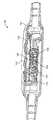
[0048]도 9a 내지 도 9f는 컨트롤 및 퀵 릴리즈 모듈의 다양한 실시예들을 예시한다.
[0049]도 10은 AR 디바이스의 하나의 간략한 실시예를 예시한다.
[0050]도 11a 및 도 11b는 헤드 장착 AR 시스템 상의 전자기 센서들의 배치의 다양한 실시예들을 예시한다.
[0051]도 12a 내지 도 12e는 전자기 센서들에 커플링될 페라이트 큐브의 다양한 실시예들을 예시한다.
[0052]도 13a 내지 도 13c는 전자기 센서들의 회로의 다양한 실시예들을 예시한다.
[0053]도 14는 헤드 및 핸드 포즈를 검출하기 위해 전자기 추적 시스템을 사용하는 예시적 방법을 예시한다.
[0054]도 15는 헤드 및 핸드 포즈를 검출하기 위해 전자기 추적 시스템을 사용하는 다른 예시적 방법을 예시한다.The drawings illustrate the design and usefulness of various embodiments of the present invention. It should be noted that the drawings are not drawn to scale, and elements of similar structures or functions are represented by the same reference numbers throughout the drawings. In order to better appreciate a method for obtaining the above-listed and other advantages and objects of various embodiments of the present invention, a more detailed description of the inventions briefly described above, with reference to specific embodiments of the invention, provided, specific embodiments of which are illustrated in the accompanying drawings. With the understanding that these drawings depict only typical embodiments of the invention and are not to be considered limiting of the scope thereof, the invention is thus described with additional features and details using the accompanying drawings. and will be explained.
1 illustrates a top view of an AR scene displayed to a user of an AR system according to an embodiment.
2A-2D illustrate various embodiments of wearable AR devices.
3 illustrates an example embodiment of a user of a wearable AR device interacting with one or more cloud servers of an AR system.
4 illustrates an example embodiment of an electromagnetic tracking system.
5 illustrates an example method of determining the position and orientation of sensors, according to an example embodiment.
6 illustrates an example diagram utilizing an electromagnetic tracking system to determine a head pose.
7 illustrates an example method of delivering virtual content to a user based on a detected head pose.
8 illustrates a schematic diagram of various components of an AR system, according to one embodiment, with an electromagnetic transmitter and electromagnetic sensors.
9A-9F illustrate various embodiments of a control and quick release module.
10 illustrates one simplified embodiment of an AR device.
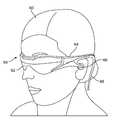
11A and 11B illustrate various embodiments of placement of electromagnetic sensors on a head mounted AR system.
12A-12E illustrate various embodiments of a ferrite cube to be coupled to electromagnetic sensors.
13A-13C illustrate various embodiments of circuitry of electromagnetic sensors.
14 illustrates an example method of using an electromagnetic tracking system to detect head and hand poses.
15 illustrates another example method of using an electromagnetic tracking system to detect head and hand poses.
[0055]도 2a-2d를 참조하면, 몇몇 일반적인 구성 옵션들이 예시된다. 도 2a-2d의 논의에 뒤따르는 상세한 설명의 일부분들에서, 인간의 VR 및/또는 AR에 대한 고품질의 편안하게 인지되는 디스플레이 시스템을 제공하는 목적들을 다루기 위한 다양한 시스템들, 서브시스템들, 및 컴포넌트들이 제시된다.2A-2D , some general configuration options are illustrated. In portions of the detailed description that follows the discussion of FIGS. 2A-2D , various systems, subsystems, and components for addressing the purposes of providing a high quality, comfortably perceived display system for human VR and/or AR. are presented
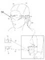
[0056]도 2a에 도시된 바와 같이, AR 시스템의 사용자(60)는 사용자의 눈들의 전방에 포지셔닝된 디스플레이 시스템(62)에 커플링된 프레임(64) 구조를 특징으로하는 헤드 장착 컴포넌트(58)를 착용하고 있는 것으로 도시된다. 스피커(66)는 도시된 구성에서 프레임(64)에 커플링되고 사용자의 외이도(ear canal)에 인접하게 포지셔닝된다(일 실시예에서는, 도시되지 않은 다른 스피커가 사용자의 다른 외이도에 인접하게 포지셔닝되어 스테레오/형상조절가능 사운드 제어를 제공한다). 디스플레이(62)는, 예컨대, 유선 리드(wired lead) 또는 무선 연결(wireless connectivity)에 의해, 다양한 구성들로 장착될 수 있는 로컬 프로세싱 및 데이터 모듈(70)에 동작가능하게 커플링(68)되는데, 여기서 다양한 구성들은 예컨대, 프레임(64)에 고정형으로 부착되는 구성, 도 2b의 실시예에 도시된 바와 같이 헬멧 또는 모자(80)에 고정형으로 부착되는 구성, 헤드폰들에 내장되는 구성, 도 2c의 실시예에 도시된 바와 같은 백팩-스타일 구성으로 사용자(60)의 몸통(82)에 탈착가능하게 부착되는 구성, 또는 도 2d의 실시예에 도시된 바와 같이 벨트-커플링 스타일 구성으로 사용자(60)의 힙(84)에 탈착가능하게 부착되는 구성을 말한다.As shown in FIG. 2A , a
[0057]로컬 프로세싱 및 데이터 모듈(70)은, 전력-효율적인 프로세서 또는 제어기뿐만 아니라 디지털 메모리, 예컨대 플래시 메모리를 포함할 수 있는데, 이들 모두는 데이터의 프로세싱, 캐싱, 및 저장을 보조하기 위해 활용될 수 있으며, 이 데이터는 (a) 프레임(64)에 동작가능하게 커플링될 수 있는 센서들, 예컨대, (카메라들과 같은) 이미지 캡처 디바이스들, 마이크로폰들, 관성 측정 유닛들, 가속도계들, 컴퍼스들, GPS 유닛들, 라디오 디바이스들 및/또는 자이로들로부터 캡처되고, 그리고/또는 (b) 이러한 프로세싱 또는 리트리벌 이후에 가능하게는 디스플레이(62)로의 패시지(passage)를 위해, 원격 프로세싱 모듈(72) 및/또는 원격 데이터 저장소(74)를 사용하여 획득되고 그리고/또는 프로세싱될 수 있다. 로컬 프로세싱 및 데이터 모듈(70)은, 예컨대, 유선 또는 무선 통신 링크들을 통해서, 원격 프로세싱 모듈(72) 및 원격 데이터 저장소(74)에 동작가능하게 커플링(76, 78)될 수 있으며, 그에 따라, 이러한 원격 모듈들(72, 74)은 서로 동작가능하게 커플링되고, 로컬 프로세싱 및 데이터 모듈(70)에 대한 자원들로서 이용가능하다.The local processing and
[0058]일 실시예에서, 원격 프로세싱 모듈(72)은 데이터 및/또는 이미지 정보를 분석하고 프로세싱하도록 구성된 하나 또는 그 초과의 비교적 강력한 프로세서들 또는 제어기들을 포함할 수 있다. 일 실시예에서, 원격 데이터 저장소(74)는, "클라우드" 자원 구성의 인터넷 또는 다른 네트워킹 구성을 통해 이용가능할 수 있는, 비교적 대규모(large-scale) 디지털 데이터 저장 설비를 포함할 수 있다. 일 실시예에서, 모든 데이터가 로컬 프로세싱 및 데이터 모듈에 저장될 수 있고, 모든 컴퓨테이션이 수행될 수 있어, 임의의 원격 모듈들로부터의 완전히 자율적인 사용이 허용된다.In one embodiment,
[0059]이제 도 3을 참조하면, 개략도는, 예컨대, 사용자의 헤드(120)에 커플링된 헤드 장착 컴포넌트(58) 및 사용자의 벨트(308)에 커플링된 로컬 프로세싱 및 데이터 모듈(70)에 상주할 수 있는 로컬 프로세싱 어셋들과 클라우드 컴퓨팅 어셋들(46) 사이의 조정을 예시하고; 따라서 컴포넌트(70)는 또한 도 3에 도시된 바와 같이 "벨트 팩(70)"으로 칭해질 수 있다. 일 실시예에서, 하나 또는 그 초과의 클라우드 서버 시스템(110)과 같은 클라우드(46) 어셋들은 예컨대, 유선 또는 무선 네트워킹(이동성을 위해서는 무선이 선호되고, 요구될 수 있는 특정 고-대역폭 또는 고-데이터-볼륨 전송들에 대해서는 유선이 선호됨)을 통해, 위에 설명된 바와 같이, 사용자의 헤드(120) 및 벨트(308)에 커플링되는 프로세서 및 메모리 구성들과 같은 로컬 컴퓨팅 어셋들 중 하나 또는 이 둘 다에 직접적으로(40, 42) 동작가능하게 커플링(115)된다. 사용자에게 로컬인 이러한 컴퓨팅 어셋들은 도 8을 참조하여 아래에 논의되는 유선 커플링(68)과 같은 유선 및/또는 무선 접속 구성들(44)을 통해 서로에게도 역시 동작 가능하게 커플링될 수 있다. 일 실시예에서, 사용자의 헤드(120)에 장착된 저-관성 및 작은 크기 서브시스템을 유지하기 위해, 사용자와 클라우드(46) 사이의 1차 전송은 벨트(308)에 장착된 서브시스템과 클라우드 사이의 링크를 통해 이루어질 수 있고, 헤드 장착 서브시스템(120)은 예컨대, 퍼스널 컴퓨팅 주변장치 연결 애플리케이션들에 현재 이용되는 것과 같은 초광대역("UWB") 연결과 같은 무선 연결을 이용하여 주로 벨트-기반 서브시스템(308)에 데이터-테더링된다.Referring now to FIG. 3 , a schematic diagram illustrates, for example, a
[0060]효율적인 로컬 및 원격 프로세싱 조정 및 사용자를 위한 적절한 디스플레이 디바이스, 이를테면, 도 2a에 도시된 사용자 인터페이스 또는 사용자 디스플레이 시스템(62), 또는 그의 변형들을 이용하여, 사용자의 현재 실제 또는 가상 위치와 관련되는 하나의 세계의 양상들은 사용자에게 전송 또는 "전달"되고 효율적인 방식으로 업데이트될 수 있다. 다시 말해서, 세계의 맵은, 사용자의 AR 시스템에 부분적으로 상주하고 클라우드 자원들에 부분적으로 상주할 수 있는 저장 위치에서 계속해서 업데이트될 수 있다. 맵(또한 "패스가능 세계 모델(passable world model)"로 지칭됨)은, 래스터 이미저리, 3-D 및 2-D 포인트들, 실세계에 관한 파라미터 정보 및 다른 정보를 포함하는 대형 데이터베이스일 수 있다. 점점 더 많은 AR 사용자들이 자신들의 실제 환경에 관한 정보를 (예컨대, 카메라들, 센서들, IMU들 등을 통해) 계속해서 캡처할수록, 맵은 점점 더 정확하고 완전해진다.[0060] Efficient local and remote processing coordination and association with the user's current real or virtual location using an appropriate display device for the user, such as the user interface or
[0061]위에서 설명된 바와 같은 구성을 이용시, 클라우드 컴퓨팅 자원들 상에 상주하고 그리고 클라우드 서버로부터 분산될 수 있는 세계의 하나의 "모델"이 존재하며, 이러한 세계는 비교적 낮은 대역폭 형태로 하나 또는 그 초과의 사용자들에게 "패스가능"할 수 있다. 이는, 실시간 비디오 데이터 또는 유사한 복합 정보를 하나의 AR 시스템으로부터 다른 AR 시스템으로 전달하는 것보다 바람직할 수 있다. 동상(즉, 도 1에 도시된 바와 같음) 근처에 서 있는 사람의 증강된 경험은 클라우드-기반 세계 모델에 의해 알려질 수 있으며, 그 서브세트는 사람의 로컬 디스플레이 디바이스로 전달되어 뷰를 완료할 수 있다. 원격 디스플레이 디바이스(예컨대, 데스크 상에 놓여 있는 개인용 컴퓨터)에 앉아 있는 사람은, 클라우드로부터 동일한 정보 섹션을 효율적으로 다운로드하여 이를 개인용 컴퓨터 디스플레이 상에 렌더링할 수 있다. 또 다른 실시예에서, 또 다른 사용자는 공원에 실시간으로 존재할 수 있고, 공유된 AR 및/또는 VR 경험을 통해 사용자에 조인하는 친구(예컨대, 개인용 컴퓨터에 있는 사람)와 함께 그 공원에서 산책을 할 수 있다. 공원 장면을 친구에게 렌더링하기 위해, AR 시스템은 거리의 위치, 공원의 나무들의 위치, 동상의 위치 등을 검출할 수 있다. 이러한 위치는 클라우드의 패스가능 세계 모델에 업로드될 수 있고, (개인용 컴퓨터에 있는) 친구는 클라우드로부터 패스가능 세계의 일부를 다운로드하고, 그런 다음, 공원에 있는 AR 사용자와 "함께 걷기" 시작할 수 있다. 물론, 일부 실시예들에서, 친구는, 패스가능 세계 모델의 아바타로서, 공원에 있는 AR 사용자에게 렌더링될 수 있어서, AR 사용자는 공원에서 가상 친구와 나란히 걸을 수 있다.[0061] Using a configuration as described above, there is one "model" of a world that resides on cloud computing resources and can be distributed from a cloud server, such a world being one or more in the form of a relatively low bandwidth. May be “passable” to more users. This may be preferable to passing real-time video data or similar complex information from one AR system to another. The augmented experience of a person standing near a statue (ie, as shown in FIG. 1 ) can be informed by a cloud-based world model, a subset of which can be passed to the person's local display device to complete the view. have. A person sitting at a remote display device (eg, a personal computer placed on a desk) can efficiently download the same section of information from the cloud and render it on the personal computer display. In another embodiment, another user may be present in the park in real time and take a walk in the park with a friend (eg, a person at a personal computer) who joins the user via a shared AR and/or VR experience. can To render a park scene to a friend, the AR system may detect the location of the street, the location of the trees in the park, the location of the statue, and the like. These locations can be uploaded to a passable world model in the cloud, and a friend (on a personal computer) can download a part of the passable world from the cloud and then start "walking with" the AR user in the park. . Of course, in some embodiments, the friend may be rendered to the AR user in the park, as an avatar of the passable world model, so that the AR user may walk alongside the virtual friend in the park.
[0062]보다 구체적으로는, 클라우드에 (그리고 이어서 다른 AR 사용자들에게) 전달될 수 있도록 세계의 세부사항들을 캡처하기 위해, 다양한 객체들과 관련된 3-D 포인트들이 환경으로부터 캡처될 수 있고, 그러한 이미지들 또는 포인트들을 캡처하는 카메라들의 포즈(즉, 세계에 대한 벡터 및/또는 오리진 포지션 정보)가 결정될 수 있다. 이러한 3-D 포인트들은, 이러한 포즈 정보와 "태그되거나" 또는 연관될 수 있다. 임의의 주어진 환경에서 동일한 포인트들을 캡처하는 많은 수의 AR 시스템들이 존재할 수 있다는 것이 인식되어야 한다. 예컨대, (제 2 AR 시스템의) 제 2 카메라에 의해 캡처된 포인트들은 제 2 카메라의 헤드 포즈를 결정하는 데 활용될 수 있다. 다시 말해, 제 1 카메라로부터 태그된 이미지들과의 비교들에 기반하여 제 2 카메라를 배향 및/또는 로컬화할 수 있다. 그런 다음, 이러한 정보는, 텍스처들을 추출하고, 맵들을 만들고, 그리고 실세계의 하나 또는 그 초과의 가상 카피들을 생성하는 데 활용될 수 있다.[0062] More specifically, 3-D points associated with various objects can be captured from the environment to capture details of the world so that they can be communicated to the cloud (and then to other AR users), such The pose (ie, vector and/or origin position information relative to the world) of the cameras capturing the images or points may be determined. These 3-D points may be “tagged” or associated with this pose information. It should be appreciated that there may be a large number of AR systems capturing the same points in any given environment. For example, points captured by the second camera (of the second AR system) may be utilized to determine the head pose of the second camera. In other words, the second camera may be orientated and/or localized based on comparisons with tagged images from the first camera. This information can then be utilized to extract textures, create maps, and create one or more virtual copies of the real world.
[0063]하나 또는 그 초과의 실시예들에서, AR 시스템은 포인트들을 생성한 2-D 이미지들 및 3-D 포인트들 둘 모두를 캡처하는 데 활용될 수 있다. 위에서 논의된 바와 같이, 일부 실시예들에서, 이러한 포인트들 및 이미지들은 클라우드 저장소 및 프로세싱 자원(예컨대, 도 3의 서버들(110))에 전송될 수 있다. 다른 실시예들에서, 태그된 2-D 이미지들이 3-D 포인트들과 함께 클라우드로 전송되도록, 이러한 정보는 임베딩된 포즈 정보(즉, 태그된 이미지들)와 함께 로컬로 캐싱될 수 있다. 사용자가 동적 장면을 관찰하는 경우, 사용자는 또한, 부가적인 정보를 클라우드 서버들까지 전송할 수 있다. 하나 또는 그 초과의 실시예들에서, 캡처된 포인트들에서의 하나 또는 그 초과의 객체들을 인지하기 위해 객체 인식기들이 (클라우드 자원 상에서 또는 로컬 시스템 상에서) 실행될 수 있다. 객체 인식기들 및 패스가능 세계 모델에 대한 더 많은 정보는, "SYSTEM AND METHOD FOR AUTMENTED AND VIRTUAL REALITY"라는 명칭의 미국 특허 출원 일련 번호 제 14/205,126호에서 찾을 수 있다. Florida의 Fort Lauderdale에 소재한 Magic Leap, Inc.에 의해 개발된 것들과 같은 증강 및 가상 현실 시스템들과 관련된 추가의 정보는: 미국 특허 출원 일련 번호 제 14/641,376호; 미국 특허 출원 일련 번호 제 14/555,585호; 미국 특허 출원 일련 번호 제 14/212,961호; 미국 특허 출원 일련 번호 제 14/690,401호; 미국 특허 출원 일련 번호 제 13/663,466호; 및 미국 특허 출원 일련 번호 제 13/684,489호에 개시되어 있다.[0063] In one or more embodiments, the AR system may be utilized to capture both 2-D images and 3-D points that generated the points. As discussed above, in some embodiments, these points and images may be transmitted to cloud storage and processing resources (eg,
[0064]"패스가능 세계 모델"을 생성하는 데 사용될 수 있는 포인트들을 캡처하기 위해, 세계에 대한 사용자의 위치, 포즈 및 배향을 정확하게 아는 것이 도움이 된다. 보다 구체적으로는, 사용자의 포지션이 세분화된 정도로 로컬화되어야 하는데, 그 이유는 사용자의 헤드 포즈뿐만 아니라 핸드 포즈(사용자가 핸드헬드 컴포넌트를 움켜잡고 있거나, 제스처를 취하고 있는 등의 경우)를 아는 것이 중요할 수 있기 때문이다. 하나 또는 그 초과의 실시예들에서, GPS 및 다른 로컬화 정보가 이러한 프로세싱에 대한 입력들로서 활용될 수 있다. 특정 AR 시스템으로부터 유도된 이미지들 및 포인트들을 프로세싱하는 데 있어서, 그리고 또한 적합한 가상 콘텐츠를 사용자에게 디스플레이하기 위해서, 사용자의 헤드, 토템들, 핸드 제스처들, 햅틱 디바이스들 등의 매우 정확한 로컬화가 바람직하다.[0064] It is helpful to know precisely the user's position, pose, and orientation with respect to the world, in order to capture points that can be used to create a “passable world model”. More specifically, the user's position should be localized to a granular degree, since knowing the user's head pose as well as the hand pose (when the user is grabbing a handheld component, gesturing, etc.) Because it can be important. In one or more embodiments, GPS and other localization information may be utilized as inputs to such processing. In processing images and points derived from a particular AR system, and also to display suitable virtual content to the user, very accurate localization of the user's head, totems, hand gestures, haptic devices, etc. is desirable. .
[0065]고정밀 로컬화를 달성하기 위한 일 접근법은, 사용자의 AR 헤드셋, 벨트 팩, 및/또는 다른 보조 디바이스들(예컨대, 토템들, 햅틱 디바이스들, 게임 기기들 등) 상에 전략적으로 배치된 전자기 센서들과 커플링된 전자기장의 사용을 수반할 수 있다. 전자기 추적 시스템들은 통상적으로, 적어도 하나의 전자기장 방출기 및 적어도 하나의 전자기장 센서를 포함한다. 전자기장 센서들은 알려진 분포를 갖는 전자기장들을 측정할 수 있다. 이러한 측정들에 기반하여, 방출기에 대한 필드 센서의 포지션 및 배향이 결정된다.[0065] One approach to achieving high-precision localization is strategically placed on the user's AR headset, belt pack, and/or other assistive devices (eg, totems, haptic devices, gaming gadgets, etc.) It may involve the use of an electromagnetic field coupled with electromagnetic sensors. Electromagnetic tracking systems typically include at least one electromagnetic field emitter and at least one electromagnetic field sensor. Electromagnetic field sensors can measure electromagnetic fields having a known distribution. Based on these measurements, the position and orientation of the field sensor relative to the emitter is determined.
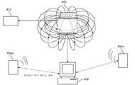
[0066]이제 도 4를 참조하면, (예컨대, Vermont, Colchester에 소재한 Polhemus (RTM), Inc., Johnson & Johnson Corporation의 Biosense(RTM) 디비전과 같은 조직들에 의해 개발되고 그리고 California, Los Gatos에 소재한 Sixense (RTM) Entertainment, Inc. 및 다른 추적 회사들에 의해 제조된 것들과 같은) 전자기 추적 시스템의 예시적 시스템이 예시된다. 하나 또는 그 초과의 실시예들에서, 전자기 추적 시스템은, 알려진 자기장을 방출하도록 구성된 전자기장 방출기(402)를 포함한다. 도 4에 도시된 바와 같이, 전자기장 방출기(402)는 전자기장 방출기(402)에 전력을 제공하기 위한 전력 공급부(410)(예컨대, 전류, 배터리들 등)에 커플링될 수 있다.[0066] Referring now to FIG. 4 (eg, Polhemus (RTM), Inc. of Colchester, Vermont, developed by organizations such as the Biosense (RTM) division of Johnson & Johnson Corporation and located in Los Gatos, California) An exemplary system of an electromagnetic tracking system (such as those manufactured by Sixense (RTM) Entertainment, Inc., and other tracking companies located there is illustrated. In one or more embodiments, the electromagnetic tracking system includes an
[0067]하나 또는 그 초과의 실시예들에서, 전자기장 방출기(402)는, 자기장들을 생성하는 몇 개의 코일들(예컨대, x, y, 및 z 방향들로 자기장을 생성하도록 서로 수직으로 포지셔닝된 적어도 3개의 코일들)을 포함한다. 이러한 자기장들은 좌표 공간을 설정하는 데 사용된다. 이는, 시스템이, 센서들(404)의 포지션을 알려진 자기장에 관하여 맵핑하는 것을 허용할 수 있으며, 이는 결과적으로, 센서들(404)의 포지션 및/또는 배향을 결정하는 것을 돕는다. 하나 또는 그 초과의 실시예들에서, 전자기 센서들(404a, 404b, 등)이 하나 또는 그 초과의 실제 객체들에 부착될 수 있다. 전자기 센서들(404)은, 방출된 전자기장을 통해 전류가 유도될 수 있는 더 작은 코일들을 포함할 수 있다. 일반적으로, "센서" 컴포넌트들(404)은, 큐브 또는 다른 컨테이너와 같은 작은 구조 내에서 함께 커플링된 3개의 상이하게-배향된(즉, 예컨대, 서로에 대해 직교하게 배향된) 코일들의 세트와 같은 작은 코일들 또는 루프들을 포함할 수 있으며, 이러한 작은 코일들 또는 루프들은 전자기 방출기(402)에 의해 방출되는 자기장으로부터 들어오는 자속을 캡처하도록 포지셔닝/배향된다. 이러한 코일들을 통해 유도되는 전류들을 비교하는 것에 의해, 그리고 서로에 대해 코일들의 상대적인 포지션 및 배향을 아는 것에 의해, 전자기 방출기(402)에 대한 센서(404)의 상대적인 포지션 및 배향이 계산될 수 있다.[0067] In one or more embodiments, the
[0068]전자기장 방출기(402)가 커플링되는 좌표계에 대한 센서(404)(및 센서가 부착되는 객체)의 포지션 및/또는 배향을 검출하기 위해, 전자기 추적 센서들(404)에 동작가능하게 커플링된 IMU("inertial measurement unit") 컴포넌트들 및 전자기 추적 센서들(404) 내의 코일들의 거동에 관한 하나 또는 그 초과의 파라미터들이 측정될 수 있다. 물론 이러한 좌표계는, 실세계에서 전자기장 방출기의 위치 또는 포즈를 결정하기 위해, 세계 좌표계로 변환될 수 있다. 하나 또는 그 초과의 실시예들에서, 전자기장 방출기(402)와 연관된 좌표 공간 내에서의 센서들(404) 각각의 포지션 및 배향을 검출하기 위해, 전자기 방출기(402)에 관하여 다수의 센서들(404)이 사용될 수 있다.operatively coupled to electromagnetic tracking sensors 404 to detect the position and/or orientation of the sensor 404 (and the object to which the sensor is attached) relative to a coordinate system to which the
[0069]몇몇 실시예들에서, AR 시스템의 헤드 장착 컴포넌트 상의 센서들에 기반하여 헤드 포즈가 이미 알려질 수 있고, 헤드 장착 AR 시스템을 통해 캡처된 이미지 데이터 및 센서 데이터에 기반하여 SLAM 분석이 수행될 수 있다는 것이 인식되어야 한다. 그러나 알려진 헤드 포즈에 대한 사용자의 핸드(예컨대, 토템과 같은 핸드헬드 컴포넌트 등)의 포지션을 아는 것이 중요할 수 있다. 즉, 헤드 포즈에 대해 핸드 포즈를 아는 것이 중요할 수 있다. 일단 헤드(센서들이 헤드 장착 컴포넌트 상에 위치된다고 가정)와 핸드 사이의 관계가 알려지면, 세계(예컨대, 세계 좌표들)에 대한 핸드의 위치가 쉽게 계산될 수 있다.[0069] In some embodiments, the head pose may already be known based on sensors on the head mounted component of the AR system, and a SLAM analysis will be performed based on the sensor data and image data captured via the head mounted AR system. It should be recognized that it can However, it may be important to know the position of the user's hand (eg, a handheld component such as a totem, etc.) relative to a known head pose. That is, it can be important to know the hand pose for the head pose. Once the relationship between the head (assuming the sensors are located on the head mounted component) and the hand is known, the position of the hand relative to the world (eg, world coordinates) can be easily calculated.
[0070]하나 또는 그 초과의 실시예들에서, 전자기 추적 시스템은 센서들(404)의 3-D 포지션들(즉, X, Y, 및 Z 방향들)을 제공할 수 있고, 2 또는 3 배향 각도들로 센서들(404)의 위치 정보를 더 제공할 수 있다. 하나 또는 그 초과의 실시예들에서, 센서들(404)의 포지션 및 배향을 결정하기 위해, IMU들의 측정들이 코일의 측정들과 비교될 수 있다. 하나 또는 그 초과의 실시예들에서, 전자기 센서들(404)의 포지션 및 배향을 결정하기 위해, 카메라들, 깊이 센서들, 및 다른 센서들과 같은, 데이터의 다양한 다른 소스들과 함께, 전자기(EM) 데이터 및 IMU 데이터 둘 다가 결합될 수 있다.[0070] In one or more embodiments, the electromagnetic tracking system may provide 3-D positions (ie, X, Y, and Z directions) of the sensors 404 , in two or three orientations. The angles may further provide location information of the sensors 404 . In one or more embodiments, measurements of the IMUs may be compared to measurements of the coil to determine the position and orientation of the sensors 404 . In one or more embodiments, in conjunction with various other sources of data, such as cameras, depth sensors, and other sensors, electromagnetic ( Both EM) data and IMU data can be combined.
[0071]하나 또는 그 초과의 실시예들에서, 이러한 정보는 제어기(406)로 송신될 수 있다(예컨대, 무선 통신, 블루투스, 등). 하나 또는 그 초과의 실시예들에서, 센서들(404)에 해당하는 포즈 정보(예컨대, 포지션 및 배향)는 비교적 높은 리프레시 레이트로 제어기(406)에게 보고될 수 있다. 통상적으로, 전자기 방출기(402)는, 테이블, 수술대, 벽, 또는 천청, 등과 같은 비교적 안정적이고 큰 객체에 커플링될 수 있으며, 하나 또는 그 초과의 센서들(404)은, 의료용 디바이스들, 핸드헬드 게이밍 컴포넌트들, 토템들, 헤드 장착 AR 시스템의 프레임, 등과 같은 더 작은 객체들에 커플링될 수 있다.In one or more embodiments, such information may be transmitted to the controller 406 (eg, wireless communication, Bluetooth, etc.). In one or more embodiments, pose information (eg, position and orientation) corresponding to sensors 404 may be reported to
[0072]대안적으로, 도 6을 참조하여 아랭에서 설명되는 바와 같이, 더 안정적인 글로벌 좌표계에 대하여 공간에서 이동하는 2개의 객체들 간의 포지션 및/또는 배향에서의 변화들 또는 델타들이 추적될 수 있는 구성을 생성하도록 전자기 추적 시스템의 다양한 피처들이 채용될 수 있다. 즉, 전자기 추적 시스템의 변형이, 헤드 장착 컴포넌트와 핸드헬드 컴포넌트 사이의 포지션 및 배향 변화들을 추적하는 데 활용될 수 있는 한편, 글로벌 좌표계(말하자면, 사용자에게 국한된 방 환경)에 대한 헤드 포즈는 다른 방식으로, 예컨대, AR 시스템의 헤드 장착 컴포넌트에 커플링될 수 있는 외부 캡처 카메라들을 사용하는 SLAM("simultaneous localization and mapping") 기술들에 의해 결정되는 구성이 도 6에 도시된다.Alternatively, changes or deltas in position and/or orientation between two objects moving in space relative to a more stable global coordinate system may be tracked, as described in Arang with reference to FIG. 6 . Various features of an electromagnetic tracking system may be employed to create a configuration. That is, a deformation of the electromagnetic tracking system can be utilized to track changes in position and orientation between a head mounted component and a handheld component, while the head pose relative to a global coordinate system (say, the user's localized room environment) is different. For example, a configuration determined by “simultaneous localization and mapping” (SLAM) techniques using external capture cameras that can be coupled to a head mounted component of an AR system is shown in FIG. 6 .
[0073]다시 도 4를 참조하면, 제어기(406)는 전자기장 방출기(402)를 제어할 수 있고, 또한, 다양한 전자기 센서들(404)로부터 측정 데이터를 캡처할 수 있다. 시스템의 다양한 컴포넌트들이 임의의 전자-기계적 또는 무선/블루투스 수단을 통해 서로 커플링될 수 있다는 것이 인식되어야 한다. 제어기(406)는 또한, 알려진 자기장, 및 자기장에 대한 좌표 공간에 관한 데이터를 저장할 수 있다. 그런 다음에, 이러한 정보는 알려진 전자기장에 해당하는 좌표 공간에 대한 센서들(404)의 포지션 및 배향을 검출하는 데 사용될 수 있으며, 이는, 그런 다음에, 사용자의 핸드의 세계 좌표들(예컨대, 전자기 방출기의 위치)을 결정하는 데 사용될 수 있다.Referring again to FIG. 4 , the
[0074]전자기 추적 시스템들의 하나의 장점은, 이들이 최소의 레이턴시 및 높은 해상도로 매우 정확한 추적 결과들을 생성할 수 있다는 점이다. 부가적으로, 전자기 추적 시스템이 반드시 광학 추적기들에 의존할 필요는 없으며, 따라서, 사용자의 시선에 있지 않은 센서들/객체들을 추적하는 것을 더 쉽게 만든다.[0074] One advantage of electromagnetic tracking systems is that they can produce highly accurate tracking results with minimal latency and high resolution. Additionally, an electromagnetic tracking system does not necessarily rely on optical trackers, thus making it easier to track sensors/objects that are not in the user's line of sight.
[0075]전자기장("v")의 세기가 코일 송신기(예컨대, 전자기장 방출기(402))로부터의 거리("r")의 3차 함수로써 감소되는(drop) 것이 인식되어야 한다. 하나 또는 그 초과의 알고리즘들은 전자기장 방출기로부터의 센서들의 거리에 기반하여 포뮬레이팅될 수 있다. 제어기(406)는 전자기장 방출기로부터 떨어진 다양한 거리들에서의 센서/객체의 포지션 및 배향을 결정하기 위한 이러한 알고리즘들로 구성될 수 있다. 전자기 방출기로부터 더 멀리 이동함에 따른 전자기장의 세기의 급격한 감소를 고려해 볼 때, 정확도, 효율성 및 낮은 레이턴시와 관련하여 개선된 결과들이 더 가까운 거리들에서 달성될 수 있다. 통상적인 전자기 추적 시스템들에서, 전자기장 방출기는 전류(예컨대, 플러그-인 전력 공급부)에 의해 전력공급되고 전자기장 방출기로부터 20ft 반경 내에 위치된 센서들을 갖는다. 센서들과 전자기장 방출기 사이의 더 짧은 반경은 AR 애플리케이션들을 포함하여 수 많은 애플리케이션들에서 더 바람직할 수 있다.[0075] It should be appreciated that the strength of the electromagnetic field (“v”) drops as a cubic function of the distance (“r”) from the coil transmitter (eg, the electromagnetic field emitter 402 ). One or more algorithms may be formulated based on the distance of the sensors from the electromagnetic field emitter. The
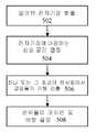
[0076]이제 도 5를 참조하면, 통상적인 전자기 추적 시스템의 기능을 설명하는 예시적인 흐름도가 간략하게 설명된다. 502에서, 알려진 전자기장이 방출된다. 하나 또는 그 초과의 실시예들에서, 전자기장 방출기는 자기장을 생성할 수 있다. 다시 말해서, 방출기의 각각의 코일은 일 방향(예컨대, x, y 또는 z)에서 전기장을 생성할 수 있다. 자기장들은 임의의 파형들로 생성될 수 있다. 하나 또는 그 초과의 실시예들에서, 축들 각각은 약간 상이한 주파수에서 오실레이팅할 수 있다.[0076] Referring now to FIG. 5, an exemplary flow diagram illustrating the functionality of a typical electromagnetic tracking system is briefly described. At 502, a known electromagnetic field is emitted. In one or more embodiments, the electromagnetic field emitter may generate a magnetic field. In other words, each coil of the emitter may generate an electric field in one direction (eg, x, y or z). The magnetic fields can be generated with arbitrary waveforms. In one or more embodiments, each of the axes may oscillate at a slightly different frequency.
[0077]504에서, 전자기장에 해당하는 좌표 공간이 결정될 수 있다. 예컨대, 도 4의 제어기(406)는 전자기장의 파라미터들에 기반하여 전자기 방출기 주위의 좌표 공간을 자동으로 결정할 수 있다. 506에서, (알려진 객체에 부착될 수 있는) 센서들에서의 코일들의 거동이 검출/측정될 수 있다. 예컨대, 코일들에 유도되는 전류가 측정될 수 있다. 다른 실시예들에서, 코일의 회전, 또는 다른 정량화가능한 거동이 추적 및 측정될 수 있다. 508에서, 이 측정은 센서(들) 및/또는 알려진 객체의 포지션 및 배향을 결정/계산하는 데 사용될 수 있다. 예컨대, 제어기는 센서들에 있는 코일들의 거동을 다양한 포지션들 또는 배향들에 상관시키는 맵핑 테이블을 참고할 수 있다. 이러한 계산들에 기반하여, 좌표 공간 내의 센서들(또는 이에 부착된 객체)의 포지션 및 배향이 결정될 수 있다. 일부 실시예들에서, 포즈/위치 정보가 센서들에서 결정될 수 있다. 다른 실시예에서, 센서들은 센서들에서 검출된 데이터를 제어기에 통신하고, 제어기는 알려진 자기장에 대한 결정된 포즈 정보(예컨대, 핸드헬드 컴포넌트에 대한 좌표들)에 대해 맵핑 테이블을 참고할 수 있다.At 504 , a coordinate space corresponding to the electromagnetic field may be determined. For example, the
[0078]AR 시스템들의 맥락에서, 전자기 추적 시스템의 하나 또는 그 초과의 컴포넌트들은 모바일 컴포넌트들의 정확한 추적을 가능하게 하기 위해 수정될 필요가 있을 수 있다. 위에서 설명된 바와 같이, 사용자의 헤드 포즈 및 배향을 추적하는 것은 수많은 AR 애플리케이션들에서 유용하다. 사용자의 헤드 포즈 및 배향의 정확한 결정은 AR 시스템이 AR 디스플레이의 적절한 포지션에서 사용자에게 적절한 가상 콘텐츠를 디스플레이하도록 허용한다. 예컨대, 가상 장면은 실제 빌딩 뒤에 숨어있는 몬스터(monster)를 포함할 수 있다. 빌딩에 대한 사용자의 헤드의 포즈 및 배향에 따라, 현실적인 AR 경험이 제공되도록 가상 몬스터의 뷰는 수정될 필요가 있을 수 있다.In the context of AR systems, one or more components of an electromagnetic tracking system may need to be modified to enable accurate tracking of mobile components. As described above, tracking a user's head pose and orientation is useful in numerous AR applications. Accurate determination of the user's head pose and orientation allows the AR system to display the appropriate virtual content to the user at the appropriate position of the AR display. For example, the virtual scene may include a monster hiding behind a real building. Depending on the pose and orientation of the user's head relative to the building, the view of the virtual monster may need to be modified to provide a realistic AR experience.
[0079]다른 실시예들에서, 가상 콘텐츠와 상호작용하는 토템, 햅틱 디바이스 또는 일부 다른 수단들의 포지션 및/또는 배향은 AR 사용자가 AR 시스템과 상호작용할 수 있게 하는 데 중요할 수 있다. 예컨대, 수많은 게이밍 애플리케이션들에서, AR 시스템은 가상 콘텐츠에 대한 실제 객체의 포지션 및 배향을 검출해야만 한다. 즉, 가상 인터페이스를 디스플레이할 때, 토템, 사용자의 핸드, 햅틱 디바이스, 또는 AR 시스템과의 상호작용을 위해 구성된 임의의 다른 실제 객체의 포지션은, 시스템이 커맨드 등을 이해하도록 하기 위해, 디스플레이된 가상 인터페이스와 관련하여 알려져야 한다. 광학적 추적 및 다른 방법들을 포함하는 종래의 로컬화 방법들은 통상적으로 높은 레이턴시 및 낮은 해상도 문제들로 어려움을 겪으며, 이는 수많은 AR 애플리케이션들에서 가상 콘텐츠를 렌더링하는 것을 어렵게 만든다.In other embodiments, the position and/or orientation of a totem, haptic device, or some other means of interacting with the virtual content may be important to enable an AR user to interact with the AR system. For example, in many gaming applications, an AR system must detect the position and orientation of a real object with respect to virtual content. That is, when displaying the virtual interface, the position of the totem, the user's hand, the haptic device, or any other real object configured for interaction with the AR system is determined by the displayed virtual interface, in order for the system to understand the command or the like. It must be known in relation to the interface. Conventional localization methods, including optical tracking and other methods, typically suffer from high latency and low resolution issues, which make rendering virtual content difficult in many AR applications.
[0080]하나 또는 그 초과의 실시예들에서, 위에 논의된 전자기 추적 시스템은 방출된 전자기장과 관련하여 하나 또는 그 초과의 객체들의 포지션 및 배향을 검출하기 위해 AR 시스템에 적응될 수 있다. 통상적인 전자기 시스템들은 대형 및 부피가 큰 전자기 방출기들(예컨대, 도 4의 402)을 갖는 경향이 있으며, 이는 통상적인 전자기 시스템들을 AR 애플리케이션들에 사용하기에는 이상적이지 않게 할 수 있다. 그러나, (예컨대, 밀리미터 범위의) 더 작은 전자기 방출기들이 AR 시스템의 맥락에서 알려진 전자기장을 방출하는 데 사용될 수 있다.[0080] In one or more embodiments, the electromagnetic tracking system discussed above may be adapted to the AR system to detect the position and orientation of one or more objects with respect to the emitted electromagnetic field. Conventional electromagnetic systems tend to have large and bulky electromagnetic emitters (eg, 402 in FIG. 4 ), which may make them less than ideal for use in AR applications. However, smaller electromagnetic emitters (eg, in the millimeter range) can be used to emit known electromagnetic fields in the context of AR systems.
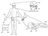
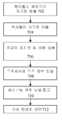
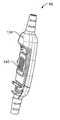
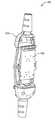
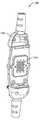
[0081]이제 도 6을 참조하면, 도시된 바와 같이, 전자기 추적 시스템이 AR 시스템에 통합될 수 있는데, 전자기장 방출기(602)는 핸드헬드 제어기(606)의 일부로서 통합된다. 하나 또는 그 초과의 실시예들에서, 핸드헬드 제어기는 게이밍 애플리케이션에 사용될 토템일 수 있다. 다른 실시예들에서, 핸드-헬드 제어기는 (예컨대, 가상 사용자 인터페이스를 통해) AR 시스템과 상호작용하는 데 사용될 수 있는 햅틱 디바이스일 수 있다. 또 다른 실시예들에서, 전자기장 방출기는, 도 2d에 도시된 바와 같이, 벨트 팩(70)의 일부로서 간단하게 통합될 수 있다. 핸드헬드 제어기(606)는 전자기장 방출기(602)에 전력을 공급하는 배터리(610) 또는 다른 전력 공급부를 포함할 수 있다.Referring now to FIG. 6 , as shown, an electromagnetic tracking system may be integrated into an AR system, with an
[0082]전자기장 방출기(602)는 또한 다른 컴포넌트들에 대한 전자기장 방출기(602)의 포지션 및/또는 배향을 결정하는 것을 보조하도록 구성된 IMU 컴포넌트(650)를 포함하거나 또는 이에 커플링될 수 있다는 것이 인식되어야 한다. 이는, 전자기장 방출기(602) 및 (이하 더욱 상세하게 논의되는) 센서들(604) 둘 다 모바일인 경우들에서 유용할 수 있다. 일부 실시예들에서, 도 6의 실시예에 도시된 바와 같이 전자기장 방출기(602)를 벨트 팩보다는 핸드헬드 제어기에 배치하는 것은, 전자기장 방출기가 벨트 팩에서의 자원들에 대해 경쟁하지 않고 오히려 핸드헬드 제어기(606)에서 자기 자신의 배터리 소스를 사용하는 것을 보장한다.[0082] It is recognized that the
[0083]하나 또는 그 초과의 실시예들에서, 전자기 센서들(604)은, 하나 또는 그 초과의 IMU들 또는 부가적인 자속 캡처 코일들(608)과 같은 다른 감지 디바이스들과 함께, 사용자의 헤드셋(58) 상의 하나 또는 그 초과의 위치들에 배치될 수 있다. 예컨대, 도 6에 도시된 바와 같이, 센서들(604, 608)은 헤드셋(58)의 양측에 배치될 수 있다. 이들 센서들(604, 608)은 다소 작게 엔지니어링되므로(따라서, 어떤 경우들에는 덜 민감할 수 있음), 측정들의 효율성 및 정밀도를 향상시키기 위해 다수의 센서들을 포함하는 것이 중요할 수 있다.In one or more embodiments, the
[0084]하나 또는 그 초과의 실시예들에서, 하나 또는 그 초과의 센서들(604, 608)은 또한 벨트 팩(620) 또는 사용자 신체의 임의의 다른 부분 상에 배치될 수 있다. 센서들(604, 608)은 전자기장 방출기(602)에 의해 방출되는 알려진 자기장과 관련하여 센서들(604, 608)(및 이들이 부착된 AR 헤드셋(58))의 포즈 및 배향을 결정하는 컴퓨팅 장치(607)(예컨대, 제어기)와 무선으로 또는 블루투스®를 통해 통신할 수 있다. 하나 또는 그 초과의 실시예들에서, 도 6에 도시된 바와 같이, 컴퓨팅 장치(607)는 벨트 팩(620)에 상주할 수 있다. 다른 실시예들에서, 컴퓨팅 장치(607)는 헤드셋(58) 자체, 또는 심지어 핸드헬드 제어기(604)에 상주할 수 있다. 하나 또는 그 초과의 실시예들에서, 컴퓨팅 장치(607)는 센서들(604, 608)의 측정들을 수신하고, 전자기장 방출기(602)에 의해 방출되는 알려진 전자기장과 관련하여 센서들(604, 608)의 포지션 및 배향을 결정할 수 있다.In one or more embodiments, one or
[0085]하나 또는 그 초과의 실시예들에서, 센서들(604, 608)의 위치 좌표들을 결정하기 위해 맵핑 데이터베이스(632)가 참고될 수 있다. 맵핑 데이터베이스(632)는 일부 실시예들에서 벨트 팩(620)에 상주할 수 있다. 예시된 실시예에서, 맵핑 데이터베이스(632)는 클라우드 자원(630) 상에 상주한다. 도 6에 도시된 바와 같이, 컴퓨팅 장치(607)는 클라우드 자원(630)과 무선으로 통신한다. 이후, AR 시스템에 의해 수집된 포인트들 및 이미지들과 함께 결정된 포즈 정보는 클라우드 자원(630)에 통신되고, 그 다음 패스가능 세계 모델(634)에 추가될 수 있다.In one or more embodiments, the
[0086]위에서 설명된 바와 같이, 종래의 전자기 방출기들은 AR 디바이스들에서 사용하기에는 너무 부피가 클 수 있다. 따라서, 전자기장 방출기는 종래의 시스템들에 비해 더 작은 코일들을 사용하여 콤팩트하게 엔지니어링될 수 있다. 그러나 전자기장의 세기가 전자기장 방출기로부터의 거리의 3차 함수로써 감소한다는 것을 고려하면, 전자기 센서들(604)과 전자기장 방출기(602) 사이의 더 짧은 반경(예컨대, 약 3-3.5ft)은 도 4에서 상술된 것과 같은 종래의 시스템들과 비교할 때 허용 가능한 전계 강도를 유지하면서 전력 소비를 감소시킬 수 있다.As described above, conventional electromagnetic emitters may be too bulky for use in AR devices. Thus, the electromagnetic field emitter can be compactly engineered using smaller coils compared to conventional systems. However, given that the strength of the electromagnetic field decreases as a cubic function of the distance from the electromagnetic field emitter, the shorter radius (eg, about 3-3.5 ft) between the
[0087]하나 또는 그 초과의 실시예들에서, 이 특징은 제어기(606) 및 전자기장 방출기(602)에 전력을 공급하는 배터리(610)의 수명을 연장시키는 데 활용될 수 있다. 대안으로, 이 특징은 전자기장 방출기(602)에서 자기장을 발생시키는 코일들의 크기를 감소시키는 데 활용될 수 있다. 그러나 동일한 세기의 자기장을 얻기 위해, 전자기장 방출기(602)의 전력이 증가될 필요가 있을 수 있다. 이는 전자기장 방출기 유닛(602)이 핸드헬드 제어기(606)에 콤팩트하게 맞춰질 수 있는 것을 가능하게 한다.In one or more embodiments, this feature may be utilized to extend the life of the
[0088]AR 디바이스들에 전자기 추적 시스템을 사용할 때 몇 가지 다른 변경들이 이루어질 수 있다. 하나 또는 그 초과의 실시예들에서, IMU-기반 포즈 추적이 사용될 수 있다. 이러한 실시예들에서, IMU들을 가능한 한 안정되게 유지하는 것은 포즈 검출 프로세스의 효율을 향상시킨다. IMU들은 50-100 밀리초까지 안정적으로 유지되도록 엔지니어링될 수 있고, 이는 포즈 업데이트/보고 레이트가 10-20Hz인 안정적인 신호들을 야기한다. 일부 실시예들은 포즈 업데이트들이 10-20Hz의 레이트로 보고될 수 있게 할 수 있는 외부 포즈 추정기 모듈을 활용할 수 있다(IMU가 시간에 따라 드리프트할 수 있기 때문에)는 것이 인식되어야 한다. 적정한 양의 시간 동안 IMU들을 안정적으로 유지함으로써, 포즈 업데이트들의 레이트는 (종래의 시스템들에서의 보다 높은 주파수들과 비교할 때) 10-20Hz로 극적으로 감소될 수 있다.[0088] Several other changes can be made when using an electromagnetic tracking system with AR devices. In one or more embodiments, IMU-based pose tracking may be used. In such embodiments, keeping the IMUs as stable as possible improves the efficiency of the pose detection process. IMUs can be engineered to remain stable up to 50-100 milliseconds, which results in stable signals with a pause update/report rate of 10-20 Hz. It should be appreciated that some embodiments may utilize an external pose estimator module that may allow pose updates to be reported at a rate of 10-20 Hz (since the IMU may drift over time). By keeping the IMUs stable for a reasonable amount of time, the rate of pause updates can be dramatically reduced to 10-20 Hz (compared to higher frequencies in conventional systems).
[0089]AR 시스템의 전력을 보존하기 위한 또 다른 방법은 10% 듀티 사이클로 전자기 추적 시스템을 실행(예컨대, 매 100 밀리초마다 지상에 대해서만 핑잉)하는 것일 수 있다. 즉, 전자기 추적 시스템은 포즈 추정치를 생성하기 위해 매 100 밀리초 중에서 10 밀리초 동안 동작한다. 이는 절전으로 바로 해석되며, 이는 결국 AR 디바이스의 크기, 배터리 수명 및 비용에 영향을 줄 수 있다.Another way to conserve power of an AR system may be to run the electromagnetic tracking system at a 10% duty cycle (eg, only pinging to the ground every 100 milliseconds). That is, the electromagnetic tracking system operates for 10 milliseconds out of every 100 milliseconds to generate the pose estimate. This translates directly into power saving, which in turn can affect the size, battery life and cost of an AR device.
[0090]하나 또는 그 초과의 실시예들에서, 듀티 사이클의 이러한 감소는 단지 하나보다는 (도시되지 않은) 2개의 핸드헬드 제어기들을 제공함으로써 전략적으로 활용될 수 있다. 예컨대, 사용자는 2개의 토템들 등을 필요로 하는 게임을 플레이하고 있을 수 있다. 또는, 다중-사용자 게임에서 2명의 사용자들이 게임을 플레이하기 위해 그들 자신의 토템들/핸드헬드 제어기들을 가질 수 있다. 1개보다는 2개의 제어기들(예컨대, 각각의 핸드에 대한 대칭 제어기들)이 사용되는 경우, 제어기들은 오프셋 듀티 사이클들로 동작할 수 있다. 동일한 개념이 또한 예컨대, 멀티-플레이어 게임을 플레이하는 2명의 상이한 사용자들에 의해 활용되는 제어기들에 적용될 수 있다.In one or more embodiments, this reduction in duty cycle may be strategically exploited by providing two handheld controllers (not shown) rather than just one. For example, the user may be playing a game that requires two totems or the like. Alternatively, in a multi-user game two users may have their own totems/handheld controllers to play the game. If two controllers rather than one (eg, symmetric controllers for each hand) are used, the controllers may operate with offset duty cycles. The same concept can also be applied to controllers utilized by two different users playing, for example, a multi-player game.
[0091]이제 도 7을 참조하면, AR 디바이스들의 맥락에서 전자기 추적 시스템을 설명하는 예시적인 흐름도가 설명된다. 702에서, 핸드헬드 제어기(606)는 자기장을 방출한다. 704에서, (헤드셋(58), 벨트 팩(620) 등에 배치된) 전자기 센서들(604)이 자기장을 검출한다. 706에서, 헤드셋/벨트의 포지션 및 배향이 센서들(604)에서 코일들/IMU들(608)의 거동에 기반하여 결정된다. 일부 실시예들에서, 센서들(604)의 검출된 거동은 컴퓨팅 장치(607)에 전달되며, 이어서 컴퓨팅 장치(607)는, 전자기장과 관련하여 센서들(604)의 포지션 및 배향(예컨대, 핸드헬드 컴포넌트에 대한 좌표들)을 결정한다. 물론, 위에서 논의된 바와 같이, 세계에 대한 헤드 포즈가 SLAM 프로세싱을 통해 알려질 수 있기 때문에, 이들 좌표들이 그 다음에 세계 좌표들로 변환될 수 있다는 것이 인식되어야 한다.Referring now to FIG. 7 , an example flow diagram illustrating an electromagnetic tracking system in the context of AR devices is described. At 702 , the
[0092] 708에서, 포즈 정보는 컴퓨팅 장치(607)(예컨대, 벨트 팩(620) 또는 헤드셋(58)에 있음)에 전달된다. 710에서, 선택적으로, 결정된 헤드 포즈 및 핸드 포즈에 기반하여 사용자에게 디스플레이될 가상 콘텐츠를 결정하도록, 패스가능 세계 모델(634)이 참고될 수 있다. 712에서, 가상 콘텐츠는 상관에 기반하여 AR 헤드셋(58)에서 사용자에게 전달될 수 있다. 위에서 설명된 흐름도가 단지 예시적 목적들을 위한 것이며, 제한하는 것으로서 해석되지 않아야 한다는 것이 인식되어야 한다.At 708 , the pose information is communicated to the computing device 607 (eg, in the
[0093]유리하게, 도 6에서 약술된 것과 유사한 전자기 추적 시스템을 사용하는 것은, 더 높은 재생률 및 더 낮은 레이턴시로 포즈 추적(예컨대, 헤드 포지션 및 배향, 다른 제어기들 및 토템들의 포지션 및 배향)을 가능하게 한다. 이는 AR 시스템으로 하여금, 포즈 정보를 계산하기 위한 광 추적 기술들과 비교할 때, 더 높은 정확도 및 더 낮은 레이턴시로 가상 콘텐츠를 프로젝팅하도록 허용한다.[0093] Advantageously, using an electromagnetic tracking system similar to that outlined in FIG. 6 allows for pose tracking (eg head position and orientation, position and orientation of other controllers and totems) with a higher refresh rate and lower latency. make it possible This allows the AR system to project virtual content with higher accuracy and lower latency when compared to light tracking techniques for calculating pose information.
[0094]도 8을 참조하면, 위에서 설명된 센서들과 유사한 많은 감지 컴포넌트들을 특징으로 하는 시스템 구성이 예시된다. 도 2a-2d 및 도 6의 참조 번호들이 도 8에서 반복된다는 것이 인식되어야 한다. 도 9a-9f를 참조하여 아래에서 설명되는 컨트롤 및 퀵 릴리즈 모듈(86)을 또한 특징으로 하는 물리적 멀티코어 리드를 여기서 사용하여, 로컬 프로세싱 및 데이터 모듈(70), 이를테면 벨트 팩(도 2d와 유사함)에 동작가능하게 커플링(68)된 헤드 장착 웨어러블 컴포넌트(58)가 도시된다. 로컬 프로세싱 및 데이터 모듈(70)은 핸드헬드 컴포넌트(606)(도 6과 유사함)에 동작가능하게 커플링(100)될 수 있다. 하나 또는 그 초과의 실시예들에서, 로컬 프로세싱 모듈(70)은 저전력 블루투스®와 같은 무선 연결을 통해 핸드-헬드 컴포넌트(606)에 커플링될 수 있다. 하나 또는 그 초과의 실시예들에서, 핸드헬드 컴포넌트(606)는 또한, 이를테면 저전력 블루투스®와 같은 무선 연결에 의해, 헤드 장착 웨어러블 컴포넌트(58)에 직접적으로 동작가능하게 커플링(94)될 수 있다.Referring to FIG. 8 , a system configuration is illustrated featuring many sensing components similar to the sensors described above. It should be appreciated that the reference numerals in FIGS. 2A-2D and 6 are repeated in FIG. 8 . Using herein a physical multicore lid that also features a control and
[0095]일반적으로, 다양한 컴포넌트들의 포즈 정보를 검출하기 위하여 IMU 데이터가 전달되는 경우, 이를테면 수백 또는 수천 사이클/초 또는 그 초과의 범위의 고-주파수 연결이 바람직할 수 있다. 다른 한편으로, 이를테면 센서(604) 및 송신기(602) 페어링들에 의해, 초당 수십 사이클들이 전자기 로컬화 감지에 적합할 수 있다. 또한, 사용자 주위의 실세계의 고정 객체들, 이를테면 벽(8)을 표현하는 글로벌 좌표계(10)가 도시된다. 클라우드 자원들(46)이 또한, 로컬 프로세싱 및 데이터 모듈(70), 헤드 장착 웨어러블 컴포넌트(58), 벽(8)에 커플링될 수 있는 자원들, 또는 글로벌 좌표계(10)에 대해 고정된 다른 아이템에 각각 동작가능하게 커플링(42, 40, 88, 90)될 수 있다. 벽(8)에 커플링된, 또는 글로벌 좌표계(10)에 대한 알려진 포지션들 및/또는 배향들을 갖는 자원들은 Wi-Fi 트랜시버(114), 전자기 방출기(602) 및/또는 수신기(604), 주어진 타입의 방사선을 방출하거나 또는 반사하도록 구성된 비콘 또는 반사기(112), 이를테면 적외선 LED 비콘, 셀룰러 네트워크 트랜시버(110), 레이더 방출기 또는 검출기(108), 라이더 방출기 또는 검출기(106), GPS 트랜시버(118), 알려진 검출가능한 패턴(122)을 갖는 포스터 또는 마커, 및 카메라(124)를 포함할 수 있다.[0095] In general, when IMU data is passed to detect pose information of various components, a high-frequency connection in the range of, for example, hundreds or thousands of cycles/second or more, may be desirable. On the other hand, tens of cycles per second may be suitable for electromagnetic localization sensing, such as with
[0096]헤드 장착 웨어러블 컴포넌트(58)는, 카메라(124) 검출기들을 보조하도록 구성된 조명 방출기들(130), 이를테면 적외선 카메라(124)용 적외선 방출기들(130) 이외에, 예시된 바와 같이, 유사한 컴포넌트들을 특징으로 한다. 하나 또는 그 초과의 실시예들에서, 헤드 장착 웨어러블 컴포넌트(58)는, 헤드 장착 웨어러블 컴포넌트(58)의 프레임 또는 기계적 플랫폼에 고정식으로 커플링되며, 전자기 수신기 센서들(604) 또는 디스플레이 엘리먼트들(62)과 같은 컴포넌트들 간에 그러한 플랫폼의 편향을 결정하도록 구성될 수 있는 하나 또는 그 초과의 스트레인 게이지들(116)을 더 포함할 수 있으며, 이를테면 플랫폼의 얇은 부분, 이를테면 도 8에서 도시된 안경-형 플랫폼 상의 코 위의 부분에서, 플랫폼의 휨이 발생했는지를 이해하는 것이 가치가 있을 수 있다.The head mounted
[0097] 헤드 장착 웨어러블 컴포넌트(58)는 또한, 프로세서(128)와 하나 또는 그 초과의 IMU들(102)을 포함할 수 있다. 컴포넌트들 각각은 바람직하게는, 프로세서(128)에 동작가능하게 커플링된다. 유사한 컴포넌트들을 특징으로 하는 핸드헬드 컴포넌트(606)와 로컬 프로세싱 및 데이터 모듈(70)이 예시된다. 도 8에서 도시된 바와 같이, 매우 많은 감지 및 연결 수단으로 인해, 그러한 시스템은 무겁고, 크고, 비교적 값비쌀 공산이 있으며, 다량의 전력을 소비할 공산이 있다. 그러나, 예시적 목적들을 위해, 매우 높은 레벨의 연결, 시스템 컴포넌트 통합, 및 포지션/배향 추적을 제공하기 위해 그러한 시스템이 활용될 수 있다. 예컨대, 그러한 구성으로 인해, 다양한 메인 모바일 컴포넌트들(58, 70, 606)은, Wi-Fi, GPS, 또는 셀룰러 신호 삼각측량을 사용하여 글로벌 좌표계에 대한 포지션 면에서 로컬화될 수 있으며; 비콘들, 전자기 추적(위에서 설명됨), 레이더, 및 라이더 시스템들은 여전히 추가적인 위치 및/또는 배향 정보 및 피드백을 제공할 수 있다. 상대 및 절대 포지션 및 배향에 관한 추가적인 정보를 제공하기 위해, 마커들 및 카메라들이 또한 활용될 수 있다. 예컨대, 동시 로컬화 및 매핑 프로토콜들 또는 "SLAM"에서 활용될 수 있는 데이터를 캡처하여, 컴포넌트(58)가 어디에 있는지 그리고 이 컴포넌트(58)가 다른 컴포넌트들에 대해 어떻게 배향되는지를 결정하기 위해, 헤드 장착 웨어러블 컴포넌트(58)에 커플링된 것으로 도시된 것들과 같은 다양한 카메라 컴포넌트들(124)이 활용될 수 있다.The head mounted
[0098]도 9a-9f를 참조하면, 컨트롤 및 퀵 릴리즈 모듈(86)의 다양한 양상들이 도시된다. 도 9a를 참조하면, 2개의 외부 하우징(134) 컴포넌트들은 기계적 래칭으로 향상될 수 있는 자기 커플링 구성을 사용하여 함께 커플링된다. 연관된 시스템의 동작을 위한 버튼들(136)이 포함될 수 있다. 도 9b는 버튼(136) 및 하부의 최상부 인쇄 회로 보드(138)가 도시되어 있는 부분 절취도를 예시한다. 도 9c를 참조하면, 버튼들(136) 및 하부의 최상부 인쇄 회로 보드(138)가 제거되어, 암형 접촉 핀 어레이(140)를 볼 수 있다. 도 9d를 참조하면, 하우징(134)의 대향하는 부분이 제거되어, 하위 인쇄 회로 보드(142)를 볼 수 있다. 도 9e에 도시된 바와 같이, 하위 인쇄 회로 보드(142)가 제거되어, 수형 접촉 핀 어레이(144)를 볼 수 있다.Referring to FIGS. 9A-9F , various aspects of the control and
[0099]도 9f의 단면도를 참조하면, 수형 핀들 또는 암형 핀들 중 적어도 하나는 이들이 각각의 핀의 종축을 따라 눌릴 수 있도록 스프링-로딩되게 구성된다. 하나 또는 그 초과의 실시예들에서, 핀들은 "포고 핀들(pogo pins)"로 불릴 수 있으며, 일반적으로 구리 또는 금과 같은 고전도성 재료를 포함할 수 있다. 어셈블리될 때, 예시된 구성은 46개의 수형 핀들을 암형 핀들과 결합(mate)할 수 있으며, 전체 어셈블리는 그것을 수동으로 당겨 분리하고 핀 어레이들(140, 144)의 둘레 주위에 배향되는 북 및 남 자석들을 사용하여 발현될 수 있는 자기 인터페이스(146) 하중(load)을 극복함으로써 둘 로(in half) 퀵-릴리즈 디커플링될 수 있다.Referring to the cross-sectional view of FIG. 9F , at least one of the male pins or the female pins is configured to be spring-loaded such that they can be depressed along the longitudinal axis of the respective pin. In one or more embodiments, the pins may be referred to as “pogo pins” and may generally include a highly conductive material such as copper or gold. When assembled, the illustrated configuration can mate 46 male pins with female pins, with the entire assembly manually pulling it apart and north and south oriented around the perimeter of
[00100] 일 실시예에서, 46개의 포고 핀들을 압축하는 것으로부터 약 2kg 하중은 약 4kg의 폐쇄 유지력으로 반작용된다. 어레이들(140, 144) 내의 핀들은 약 1.3mm만큼 분리될 수 있고, 핀들은 USB 3.0, HDMI 2.0, I2S 신호들, GPIO 및 MIPI 구성들을 지원하기 위한 연선들 또는 다른 조합들과 같은 다양한 타입들의 전도 라인들, 및 일 실시예에서, 약 4amps/5 볼트까지를 위해 구성되는 고전류 아날로그 라인들 및 접지들에 동작 가능하게 커플링될 수 있다.[00100] In one embodiment, a load of about 2 kg from compressing 46 pogo pins is counteracted with a holding force of about 4 kg. The pins in the
[00101]도 10을 참조하면, 다양한 컴포넌트들의 무게 및 부피를 최소화하고, 그리고 예컨대, 도 10에 특징화된(featured) 헤드 장착 컴포넌트(58)의 것과 같이 비교적 슬림한 헤드 장착 컴포넌트에 이를 수 있도록, 최소화된 컴포넌트/피처 세트를 갖는 것이 도움이 된다. 따라서, 도 8에 도시된 다양한 컴포넌트들의 다양한 치환들 및 조합들이 활용될 수 있다.Referring to FIG. 10 , to minimize the weight and volume of the various components, and to lead to a relatively slim head mounted component, such as that of the head mounted
[00102]도 11a를 참조하면, 헤드 장착 컴포넌트(58)에 커플링되는 전자기 감지 코일 어셈블리(604, 예컨대, 하우징에 커플링되는 3개의 개별적인 코일들)가 도시된다. 이러한 구성은 전체 어셈블리에 부가적인 기하구조(즉, 돌출부)를 부가하며, 이는 바람직하지 않을 수 있다. 도 11b를 참조하면, 도 11a의 구성에서와 같이 박스 또는 단일 하우징에 코일들을 하우징하기 보다는, 개별적인 코일들이 도 11b에 도시된 바와 같이 헤드 장착 컴포넌트들(58)의 다양한 구조들로 통합될 수 있다. 예컨대, x-축 코일(148)은 헤드 장착 컴포넌트(58)의 일 부분(예컨대, 프레임의 중심)에 배치될 수 있다. 유사하게, y-축 코일(150)은 헤드 장착 컴포넌트(58)의 다른 부분(예컨대, 프레임의 양쪽 최하부 측)에 배치될 수 있다. 유사하게, z-축 코일(152)은 헤드 장착 컴포넌트(58)의 또 다른 부분(예컨대, 프레임의 양쪽 최상부 측)에 배치될 수 있다.Referring to FIG. 11A , an electromagnetic sensing coil assembly 604 (eg, three separate coils coupled to a housing) coupled to a
[00103]도 12a 내지 도 12e는 필드 감도를 증가시키기 위해 전자기 센서에 커플링되는 페라이트 코어를 특징으로 하는 다양한 구성들을 예시한다. 도 12a를 참조하면, 페라이트 코어는 솔리드 큐브(1202) 일 수 있다. 솔리드 큐브가 필드 감도를 증가시키는 데 가장 효과적 일 수 있지만, 이는 또한 도 12b-12e에 도시된 나머지 구성들과 비교할 때 가장 무거울 수도 있다. 도 12b를 참조하면, 복수의 페라이트 디스크들(1204)이 전자기 센서에 커플링될 수 있다. 유사하게, 도 12c를 참조하면, 일 축 공기 코어(1206)를 갖는 솔리드 큐브가 전자기 센서에 커플링될 수 있다. 도 12c에 도시된 바와 같이, 개방 공간(즉, 공기 코어)은 하나의 축을 따라 솔리드 큐브에 형성될 수 있다. 이는 필요한 필드 감도를 여전히 제공하면서 큐브의 무게를 감소시킬 수 있다. 또 다른 실시예에서, 도 12d를 참조하면, 3 축 공기 코어(1208)를 갖는 솔리드 큐브가 전자기 센서에 커플링될 수 있다. 이 구성에서, 솔리드 큐브는 3개의 모든 축들을 따라 속이 비워져서 큐브의 무게를 상당히 감소시킨다. 도 12e를 참조하면, 플라스틱 하우징(1210)을 갖는 페라이트 로드(ferrite rod)가 또한 전자기 센서에 커플링될 수 있다. 도 12b 내지 도 12e의 실시예들은, 위에서 논의된 바와 같이, 도 12a의 솔리드 코어 구성보다 무게가 더 가볍고 질량을 절감하는 데 활용될 수 있다는 것이 인식되어야 한다.12A-12E illustrate various configurations featuring a ferrite core coupled to an electromagnetic sensor to increase field sensitivity. Referring to FIG. 12A , the ferrite core may be a
[00104]도 13a-13c를 참조하면, 시분할 멀티플렉싱("TDM")이 또한 질량을 절감하는 데 활용될 수 있다. 예컨대, 도 13a를 참조하면, 3-코일 전자기 수신기 센서에 대한 종래의 로컬 데이터 프로세싱 구성이 도시되며, 여기서 아날로그 전류들은 X, Y 및 Z 코일들(1302, 1304 및 1306) 각각으로부터 들어오고, 별개의 전치-증폭기(1308)로 진행하고, 별개의 대역통과 필터(1310)로, 별개의 전치-증폭기(1312)로, 아날로그-디지털 변환기(1314)를 통과하여, 궁극적으로는 디지털 신호 프로세서(1316)로 진행된다.13A-13C , time division multiplexing (“TDM”) may also be utilized to save mass. For example, referring to FIG. 13A , a conventional local data processing configuration for a three-coil electromagnetic receiver sensor is shown, wherein analog currents come from each of the X, Y, and Z coils 1302, 1304, and 1306, and separate It proceeds to the
[00105]도 13b의 송신기 구성 및 도 13c의 수신기 구성을 참조하면, 시분할 멀티플렉싱은 각각의 코일 센서 체인이 자기 자신의 증폭기들 등을 요구하지 않도록 하드웨어를 공유하기 위해 활용될 수 있다. 이것은 도 13b에 도시된 TDM 스위치(1320)를 통해 달성될 수 있는데, 이는 동일한 세트의 하드웨어 컴포넌트들(증폭기들 등)을 사용하여 다수개의 송신기들 및 수신기들로부터의 그리고 다수개의 송신기들 및 수신기들로의 신호들의 프로세싱을 가능하게 한다. 하드웨어 오버헤드를 절약하기 위해 멀티플렉싱하는 것 및 센서 하우징들을 제거하는 것 이외에, 신호 대 잡음비들은 하나 초과의 세트의 전자기 센서들을 가짐으로써 증가될 수 있고, 각각의 세트는 단일의 더 큰 코일 세트에 비해 비교적 작다. 또한, 일반적으로 근접한 다수의 감지 코일들을 갖기 위해 필요한 낮은-사이드 주파수(low-side frequency) 한계들은 대역폭 요건 개선들을 가능하게 하도록 개선될 수 있다. 멀티플렉싱이 일반적으로 시간에 따라 라디오 주파수 신호들의 수신을 확산시키고 이는 일반적으로 보다 조악한(coarser) 신호들을 초래한다는 점에서, 멀티플렉싱과의 트레이드오프가 존재할 수 있다는 점이 주목되어야 한다. 따라서, 더 큰 코일 직경들이 멀티플렉싱된 시스템들에 요구될 수 있다. 예컨대, 멀티플렉싱된 시스템이 측면 치수가 9mm인 큐빅 코일 센서 박스를 요구할 수 있는 경우, 멀티플렉싱되지 않은 시스템은 유사한 성능을 위해 단지 측면 치수가 7mm인 큐빅 코일 박스를 요구할 수 있다. 따라서, 기하구조 및 질량을 최소화하는데 트레이드오프들이 존재할 수 있다는 점이 주목되어야 한다.[00105] Referring to the transmitter configuration of FIG. 13B and the receiver configuration of FIG. 13C, time division multiplexing may be utilized to share hardware such that each coil sensor chain does not require its own amplifiers or the like. This can be accomplished via the
[00106]특정 시스템 컴포넌트, 이를테면, 헤드 장착 컴포넌트(58)가 2개 또는 그 초과의 전자기 코일 센서 세트들을 특징으로 하는 다른 실시예에서, 시스템은 시스템의 성능을 최적화하기 위해 서로 가장 가까운 센서 및 전자기 방출기 페어링을 선택적으로 활용하도록 구성될 수 있다.[00106] In other embodiments where a particular system component, such as the head mounted
[00107]도 14를 참조하면, 일 실시예에서, 사용자가 자신의 웨어러블 컴퓨팅 시스템에 전력을 공급(160)한 이후에, 헤드 장착 컴포넌트 어셈블리는 실제 세계 글로벌 좌표계에 대한 헤드 포즈(즉, 포지션 및 배향)를 결정하고 업데이트하기 위해 IMU와 카메라 데이터(이를테면, 더 큰 원시(raw) 프로세싱 마력이 존재할 수 있는 벨트 팩 프로세서에서, 예컨대, SLAM 분석을 위해 사용되는 카메라 데이터)의 조합을 캡처(162)할 수 있다. 사용자는 또한, 예컨대, 증강 현실 게임을 플레이하기 위해 핸드헬드 컴포넌트를 활성화(164)할 수 있고, 핸드헬드 컴포넌트는 벨트 팩 및 헤드 장착 컴포넌트 중 하나 또는 둘 모두에 동작가능하게 커플링된 전자기 송신기를 포함(166)할 수 있다. 헤드 장착 컴포넌트에 커플링된 하나 또는 그 초과의 전자기장 코일 수신기 세트들(예컨대, 한 세트는 3개의 상이하게-배향된 개별 코일들임)이 전자기 송신기로부터의 자속을 캡처하기 위해 사용될 수 있다. 이 캡처된 자속은 헤드 장착 컴포넌트와 핸드헬드 컴포넌트 간의 포지션 또는 배향 차이(또는 "델타")를 결정하기 위해 활용(168)될 수 있다.Referring to FIG. 14 , in one embodiment, after the user powers up 160 his wearable computing system, the head mounted component assembly performs the head pose (i.e., position and Capture 162 a combination of IMU and camera data (e.g., camera data used for SLAM analysis, e.g., in a belt pack processor where greater raw processing horsepower may be present) to determine and update orientation). can do. The user may also activate 164 the handheld component, eg, to play an augmented reality game, the handheld component comprising an electromagnetic transmitter operatively coupled to one or both of the belt pack and the head mounted component. may include 166 . One or more electromagnetic field coil receiver sets coupled to the head mounted component (eg, one set is three differently-oriented individual coils) may be used to capture magnetic flux from the electromagnetic transmitter. This captured magnetic flux may be utilized 168 to determine a position or orientation difference (or “delta”) between the head mounted component and the handheld component.
[00108]하나 또는 그 초과의 실시예들에서, 글로벌 좌표계에 대해 포즈를 결정하는 것을 보조하는 헤드 장착 컴포넌트와 헤드 장착 컴포넌트에 대해 핸드헬드의 상대적 위치 및 배향을 결정하는 것을 보조하는 핸드헬드의 조합은, 시스템이 글로벌 좌표계에 대해 각각의 컴포넌트가 어디에 위치되는지를 일반적으로 결정하게 허용하고, 따라서, 사용자의 헤드 포즈 및 핸드헬드 포즈는 핸드헬드 컴포넌트의 움직임들 및 회전들을 사용하는 증강 현실 이미지 피처들 및 상호작용의 프리젠테이션을 위해 바람직하게는, 비교적 낮은 레이턴시로 추적(170)될 수 있다.[00108] In one or more embodiments, a combination of a head mounted component that assists in determining a pose relative to a global coordinate system and a handheld that assists in determining a relative position and orientation of the handheld relative to the head mounted component allows the system to generally determine where each component is located with respect to the global coordinate system, and thus the user's head pose and handheld pose are augmented reality image features using the movements and rotations of the handheld component. and for presentation of interactions, preferably with relatively low latency tracked 170 .
[00109]도 15를 참조하면, 사용자의 헤드 포즈 및 핸드헬드 포즈가 핸드헬드 컴포넌트의 움직임들 및 회전들을 사용하는 증강 현실 이미지 피처들 및 상호작용의 프리젠테이션을 위해, 바람직하게는 비교적 낮은 레이턴시로 추적(180)될 수 있도록, 시스템이 헤드 장착 컴포넌트 및 핸드헬드 컴포넌트 둘다의 포즈를 결정하는 것(172 및 176, 178)을 보조하기 위해 이용가능한 더 많은 감지 디바이스들 및 구성들을 가지는 것을 제외하고 실시예가 도 14의 것과 다소 유사하게 예시된다.15 , the user's head pose and handheld pose are preferably at relatively low latency, for presentation of augmented reality image features and interaction using the movements and rotations of the handheld component. Implemented except that the system has more sensing devices and configurations available to assist in determining the
[00110]구체적으로, 사용자가 자신의 웨어러블 컴퓨팅 시스템에 전력을 공급(160)한 이후에, 헤드 장착 컴포넌트는 실세계 글로벌 좌표계에 대한 헤드 포즈를 결정하고 업데이트하기 위해 SLAM 분석을 위한 IMU와 카메라 데이터의 조합을 캡처한다. 시스템은 글로벌 좌표계의 다양한 양상들에 또는 하나 또는 그 초과의 이동가능한 컴포넌트들에 연결될 수 있는, Wi-Fi, 셀룰러, 비콘들, 레이더, 라이더, GPS, 마커들 및/또는 다른 카메라들과 같이, 환경에서 다른 로컬화 자원들의 존재를 검출하도록 추가로 구성(172)될 수 있다.[00110] Specifically, after the user powers up 160 his wearable computing system, the head mounted component uses the IMU and camera data for SLAM analysis to determine and update the head pose relative to the real world global coordinate system. Capture the combination. The system may be coupled to various aspects of the global coordinate system or to one or more movable components, such as Wi-Fi, cellular, beacons, radar, lidar, GPS, markers and/or other cameras; It may be further configured 172 to detect the presence of other localization resources in the environment.
[00111]사용자는 또한, 예컨대, 증강 현실 게임을 플레이하기 위해 핸드헬드 컴포넌트를 활성화(174)할 수 있고, 핸드헬드 컴포넌트는 벨트 팩 및 헤드 장착 컴포넌트 중 하나 또는 둘 모두에 동작가능하게 커플링된 전자기 송신기를 포함(176)할 수 있다. 다른 로컬화 자원들이 또한 유사하게 활용될 수 있다. 헤드 장착 컴포넌트에 커플링된 하나 또는 그 초과의 전자기장 코일 수신기 세트들(예컨대, 한 세트는 3개의 상이하게-배향된 개별 코일들임)이 전자기 송신기로부터의 자속을 캡처하기 위해 사용될 수 있다. 이 캡처된 자속은 헤드 장착 컴포넌트와 핸드헬드 컴포넌트 간의 포지션 또는 배향 차이(또는 "델타")를 결정하기 위해 활용(178)될 수 있다.[00111] The user may also activate 174 the handheld component, eg, to play an augmented reality game, the handheld component operatively coupled to one or both of the belt pack and the head mounted component. An electromagnetic transmitter may be included (176). Other localization resources may also be similarly utilized. One or more electromagnetic field coil receiver sets coupled to the head mounted component (eg, one set is three differently-oriented individual coils) may be used to capture magnetic flux from the electromagnetic transmitter. This captured magnetic flux may be utilized 178 to determine a position or orientation difference (or “delta”) between the head mounted component and the handheld component.
[00112]따라서, 사용자의 헤드 포즈 및 핸드헬드 포즈는 핸드헬드 컴포넌트의 움직임 또는 회전들을 사용하는 AR 시스템과의 상호작용을 위해 그리고/또는 AR 컨텐츠의 프리젠테이션을 위해 비교적 낮은 레이턴시로 추적(180)될 수 있다.[00112] Accordingly, the user's head pose and handheld pose are tracked 180 with relatively low latency for interaction with an AR system using movement or rotations of the handheld component and/or for presentation of AR content. can be
[00113]본 발명의 다양한 예시적인 실시예들이 본원에서 설명된다. 비-제한적인 의미로 이들 예들에 대한 참조가 이루어진다. 그 예들은 본 발명의 더 광범위한 적용가능한 양상들을 예시하기 위해 제공된다. 본 발명의 실제 사상 및 범위를 벗어나지 않으면서, 다양한 변화들이 설명된 본 발명에 대해 이루어질 수 있고 등가물들이 대체될 수 있다. 게다가, 특정 상황, 재료, 물질의 조성, 프로세스, 프로세스 동작(들) 또는 단계(들)을 본 발명의 목적(들), 사상 또는 범위에 적응시키기 위해 많은 수정들이 이루어질 수 있다. 추가로, 당업자들에 의해 인지될 바와 같이, 본원에서 설명되고 예시된 개별적인 변형들 각각은, 본 발명들의 범위 및 사상을 벗어나지 않으면서, 다른 수개의 실시예들 중 임의의 실시예의 특징들로부터 용이하게 구별되거나 또는 그 특징들과 결합될 수 있는 개별 컴포넌트들 및 특징들을 갖는다. 그러한 모든 수정들은 본 개시내용과 연관된 청구항들의 범위 내에 있는 것으로 의도된다.[00113] Various exemplary embodiments of the invention are described herein. Reference is made to these examples in a non-limiting sense. The examples are provided to illustrate the broader applicable aspects of the present invention. Various changes may be made to the invention described and equivalents may be substituted without departing from the true spirit and scope of the invention. In addition, many modifications may be made to adapt a particular situation, material, composition of matter, process, process operation(s) or step(s) to the objective(s), spirit or scope of the present invention. Additionally, as will be appreciated by those skilled in the art, each of the individual variations described and illustrated herein may depart from the features of any of several other embodiments without departing from the scope and spirit of the inventions. It has individual components and features that can be distinctly distinguished or combined with those features. All such modifications are intended to be within the scope of the claims associated with this disclosure.
[00114]본 발명은 대상 디바이스들을 사용하여 수행될 수 있는 방법들을 포함한다. 방법들은 그러한 적절한 디바이스를 제공하는 동작을 포함할 수 있다. 그러한 제공은 최종 사용자에 의해 수행될 수 있다. 다시 말해서, "제공하는" 동작은 단지 대상 방법에서 필요한 디바이스를 제공하도록 최종 사용자가 획득, 액세스, 접근, 포지셔닝, 셋업, 활성화, 파워-업 또는 그렇지 않으면 동작하게 요구한다. 본원에서 언급된 방법들은 이벤트들의 언급된 순서뿐만 아니라, 논리적으로 가능한 언급된 이벤트들의 임의의 순서로 수행될 수 있다.[00114] The present invention includes methods that may be performed using target devices. Methods may include the act of providing such a suitable device. Such provision may be performed by the end user. In other words, the act of “providing” merely requires the end user to obtain, access, access, position, set up, activate, power-up or otherwise operate to provide the necessary device in the subject method. The methods recited herein may be performed in any order of events logically possible, not just the stated order of events.
[00115]재료 선택 및 제조에 관한 세부사항들과 함께 본 발명의 예시적인 양상들이 위에 기재되었다. 본 발명의 다른 세부사항들에 대해 말하자면, 이들은 위에서-참조된 특허들 및 공개문헌들과 관련하여 인지될 수 있을 뿐만 아니라 일반적으로 당업자들에게 알려지거나 당업자들에 의해 인지될 수 있다. 통상적으로 또는 논리적으로 이용되는 바와 같은 부가적인 동작들의 측면들에서 본 발명의 방법-기반 양상들이 똑같이 적용될 수 있다.[00115] Exemplary aspects of the invention have been described above along with details regarding material selection and fabrication. As for other details of the present invention, they may be recognized in connection with the above-referenced patents and publications as well as generally known to or recognized by those skilled in the art. The method-based aspects of the present invention are equally applicable in terms of additional operations as used conventionally or logically.
[00116]게다가, 본 발명이 다양한 특징들을 선택적으로 통합하는 수개의 예들을 참조하여 설명되었지만, 본 발명은, 본 발명의 각각의 변형에 관해 고려될 때 설명되거나 또는 표시되는 것으로 제한되지 않는다. 본 발명의 진정한 사상 및 범위를 벗어나지 않으면서, 다양한 변화들이 설명된 본 발명에 대해 이루어질 수 있고 (본원에서 인용되든지 또는 일부 간략화를 위해 포함되지 않든지 간에) 등가물들이 대체될 수 있다. 게다가, 값들의 범위가 제공되는 경우, 그 범위의 상한과 하한 간의 모든 각각의 중간값 및 그 언급된 범위 내의 임의의 다른 언급된 또는 중간값이 본 발명 내에 포함된다는 것이 이해된다.Moreover, although the invention has been described with reference to several examples that selectively incorporate various features, the invention is not limited to what has been described or shown when contemplated with respect to each variant of the invention. Various changes may be made to the invention described and equivalents may be substituted (whether recited herein or not included for some brevity) without departing from the true spirit and scope of the invention. Moreover, when a range of values is provided, it is understood that each intermediate value between the upper and lower limits of that range and any other stated or intermediate value within that stated range is encompassed within the invention.
[00117]또한, 설명된 본 발명의 변형들의 임의의 선택적인 특징이 독립적으로 또는 본원에서 설명된 특징들 중 임의의 하나 또는 그 초과와 조합하여 기재되고 청구될 수 있다는 것이 고려된다. 단수형 아이템들에 대한 참조는 복수의 동일한 아이템들이 존재하는 가능성을 포함한다. 보다 상세하게는, 본원에서 그리고 그와 연관된 청구항들에서 사용되는 바와 같이, 단수형들은, 특별히 달리 언급되지 않으면 복수의 지시물들을 포함한다. 다시 말해서, 단수형들의 사용은, 본 개시내용과 연관된 위의 설명뿐만 아니라 청구항들에서 대상 아이템 중 "적어도 하나"를 허용한다. 그러한 청구항들이 임의의 선택적인 엘리먼트를 배제하도록 작성될 수 있다는 것이 추가로 주목된다. 그러므로, 이러한 진술은 청구항 엘리먼트들의 인용과 관련하여 "단독으로", "유일한" 등과 같은 그러한 배타적인 전문용어의 사용 또는 "네거티브" 제한의 사용에 대한 선행 기반의 역할을 하는 것으로 의도된다.[00117] It is also contemplated that any optional feature of the described variants of the invention may be described and claimed independently or in combination with any one or more of the features described herein. Reference to singular items includes the possibility that a plurality of identical items exist. More particularly, as used herein and in the claims associated therewith, singular forms include plural referents unless specifically stated otherwise. In other words, the use of the singular permits “at least one” of the subject item in the claims as well as the description above in connection with this disclosure. It is further noted that such claims may be written to exclude any optional element. Therefore, this statement is intended to serve as an antecedent basis for use of such exclusive terminology as "solely", "only", etc. or use of a "negative" limitation in connection with the recitation of claim elements.
[00118]그러한 배타적인 전문용어의 사용없이, 본 개시내용와 연관된 청구항들의 용어 "포함하는(comprising)"은, 주어진 수의 엘리먼트들이 그러한 청구항들에서 열거되는지 또는 특징의 부가가 그러한 청구항들에서 기재된 엘리먼트의 성질을 변환시키는 것으로 간주될 수 있는지에 관계없이, 임의의 부가적인 엘리먼트의 포함을 허용해야 한다. 본원에서 특별히 정의된 것을 제외하고, 본원에서 사용된 모든 기술 용어들 및 과학 용어들은 청구 유효성을 유지하면서 가능한 일반적으로 이해되는 의미로 광범위하게 주어질 것이다.[00118] Without the use of such exclusive terminology, the term “comprising” in claims associated with this disclosure means that a given number of elements are recited in those claims or the element in which the addition of a feature is recited in those claims. Should allow the inclusion of any additional element, whether or not it can be considered transforming the property of Except as specifically defined herein, all technical and scientific terms used herein are to be given the broadest possible commonly understood meaning while maintaining the validity of the claims.
[00119]본 발명의 범위는 제공된 예들 및/또는 대상 명세서로 제한되는 것이 아니라 오히려 본 개시내용과 연관된 청구항 문언의 범위에 의해서만 제한된다.[00119] The scope of the invention is not limited by the examples provided and/or the subject specification, but rather only by the scope of the claim language associated with this disclosure.
Claims (26)
Translated fromKorean전역 좌표계에 대한 AR 디스플레이 시스템의 헤드 장착 컴포넌트의 적어도 포지션 및 배향을 결정하는 단계 ― 상기 AR 디스플레이 시스템의 헤드 장착 컴포넌트는 상기 전역 좌표계에 대해 이동가능함 ―;
전자기장 방출기를 통해, 알려진 자기장을 방출하는 단계 ― 상기 전자기장 방출기는 상기 AR 디스플레이 시스템의 핸드헬드(hand-held) 컴포넌트에 하우징(housing)되고, 상기 AR 디스플레이 시스템의 핸드헬드 컴포넌트는 상기 AR 디스플레이 시스템의 헤드 장착 컴포넌트 및 상기 전역 좌표계에 대해 이동가능함 ―;
전자기 센서를 통해, 방출된 알려진 자기장의 결과로서의 상기 전자기 센서에서의 자속과 관련된 파라미터를 측정하는 단계;
상기 전자기 센서에서의 자속과 관련된 측정된 상기 파라미터, 그리고 상기 AR 디스플레이 시스템의 헤드 장착 컴포넌트의 결정된 상기 포지션 및 배향에 적어도 부분적으로 기반하여, 상기 전역 좌표계에 대한 상기 AR 디스플레이 시스템의 핸드헬드 컴포넌트의 적어도 포지션 및 배향을 결정하는 단계; 및
상기 전역 좌표계에 대한 상기 AR 디스플레이 시스템의 핸드헬드 컴포넌트의 결정된 상기 포지션 및 배향에 적어도 부분적으로 기반하여, 사용자에게 가상 콘텐츠를 디스플레이하는 단계를 포함하고,
상기 전자기 센서는, 3개의 방향들에서 자속을 측정하기 위한 적어도 3개의 코일들을 포함하며,
상기 적어도 3개의 코일들은, 상기 AR 디스플레이 시스템의 헤드 장착 컴포넌트의 상이한 위치들에서 상기 헤드 장착 컴포넌트 내에 통합되는, 증강 현실을 디스플레이하기 위한 방법.A method for displaying augmented reality (AR), comprising:
determining at least a position and orientation of a head mounted component of an AR display system with respect to a global coordinate system, wherein the head mounted component of the AR display system is movable with respect to the global coordinate system;
emitting, through an electromagnetic field emitter, a known magnetic field, wherein the electromagnetic field emitter is housed in a hand-held component of the AR display system, the handheld component of the AR display system being movable relative to the head mounted component and the global coordinate system;
measuring, via the electromagnetic sensor, a parameter related to magnetic flux at the electromagnetic sensor as a result of an emitted known magnetic field;
based at least in part on the measured parameter related to magnetic flux in the electromagnetic sensor and the determined position and orientation of the head mounted component of the AR display system at least in part of the handheld component of the AR display system with respect to the global coordinate system. determining position and orientation; and
displaying virtual content to a user based at least in part on the determined position and orientation of a handheld component of the AR display system with respect to the global coordinate system;
The electromagnetic sensor comprises at least three coils for measuring magnetic flux in three directions,
wherein the at least three coils are integrated into the head mounted component at different locations of the head mounted component of the AR display system.
디스플레이 시스템을 헤드 장착 컴포넌트에 하우징하는 단계를 더 포함하는, 증강 현실을 디스플레이하기 위한 방법.The method of claim 1,
A method for displaying augmented reality, further comprising housing the display system in a head mounted component.
상기 전역 좌표계에 대한 AR 디스플레이 시스템의 헤드 장착 컴포넌트의 포지션 및 배향은, 헤드 포즈 정보를 결정하기 위해 수행되는 SLAM 분석에 적어도 부분적으로 기반하여 결정되고,
상기 전자기 센서는, 디스플레이 시스템을 하우징하는 상기 헤드 장착 컴포넌트에 동작가능하게 커플링되는, 증강 현실을 디스플레이하기 위한 방법.The method of claim 1,
a position and orientation of a head mounted component of an AR display system with respect to the global coordinate system is determined based, at least in part, on a SLAM analysis performed to determine head pose information;
wherein the electromagnetic sensor is operatively coupled to the head mounted component housing a display system.
상기 헤드 장착 컴포넌트에 동작가능하게 커플링된 하나 또는 그 초과의 카메라들을 통해 이미지 데이터를 캡처하는 단계를 더 포함하며,
상기 SLAM 분석은 상기 하나 또는 그 초과의 카메라들에 의해 캡처된 데이터에 적어도 기반하여 수행되는, 증강 현실을 디스플레이하기 위한 방법.8. The method of claim 7,
further comprising capturing image data via one or more cameras operatively coupled to the head mounted component;
wherein the SLAM analysis is performed based at least on data captured by the one or more cameras.
전자기 센서들은 하나 또는 그 초과의 IMU(inertial measurement unit)들을 포함하는, 증강 현실을 디스플레이하기 위한 방법.The method of claim 1,
The method for displaying augmented reality, wherein the electromagnetic sensors include one or more inertial measurement units (IMUs).
상기 전역 좌표계에 대한 AR 디스플레이 시스템의 헤드 장착 컴포넌트의 결정된 상기 포지션 및 배향에 적어도 부분적으로 기반하여, 하나 또는 그 초과의 가상 콘텐츠들과의 상호작용을 검출하는 단계를 더 포함하는, 증강 현실을 디스플레이하기 위한 방법.The method of claim 1,
based at least in part on the determined position and orientation of a head mounted component of an AR display system with respect to the global coordinate system, detecting interaction with one or more virtual contents. how to do it.
검출된 상호작용에 적어도 부분적으로 기반하여 상기 사용자에게 가상 콘텐츠를 디스플레이하는 단계를 더 포함하는, 증강 현실을 디스플레이하기 위한 방법.13. The method of claim 12,
and displaying virtual content to the user based at least in part on the detected interaction.
상기 전자기장 방출기에 의해 방출되는 상기 알려진 자기장을 컨트롤 및 퀵 릴리즈 모듈(control and quick release module)을 통해 디커플링(decoupling)하는 단계를 더 포함하는, 증강 현실을 디스플레이하기 위한 방법.The method of claim 1,
decoupling the known magnetic field emitted by the electromagnetic field emitter via a control and quick release module.
상기 전역 좌표계에 대한 AR 디스플레이 시스템의 헤드 장착 컴포넌트의 결정된 상기 포지션 및 배향을 부가적인 로컬화 자원들을 통해 결정하는 단계를 더 포함하는, 증강 현실을 디스플레이하기 위한 방법.The method of claim 1,
and determining the determined position and orientation of a head mounted component of an AR display system with respect to the global coordinate system via additional localization resources.
상기 부가적인 로컬화 자원들은 GPS 수신기를 포함하는, 증강 현실을 디스플레이하기 위한 방법.16. The method of claim 15,
wherein the additional localization resources include a GPS receiver.
상기 부가적인 로컬화 자원들은 비콘(beacon)을 포함하는, 증강 현실을 디스플레이하기 위한 방법.16. The method of claim 15,
wherein the additional localization resources include a beacon.
상기 전자기 센서는 논-솔리드 페라이트 큐브(non-solid ferrite cube)를 포함하는, 증강 현실을 디스플레이하기 위한 방법.The method of claim 1,
wherein the electromagnetic sensor comprises a non-solid ferrite cube.
상기 전자기 센서는 페라이트 디스크들의 스택(stack)을 포함하는, 증강 현실을 디스플레이하기 위한 방법.The method of claim 1,
wherein the electromagnetic sensor comprises a stack of ferrite disks.
상기 전자기 센서는 복수의 페라이트 로드(rod)들을 포함하며, 상기 페라이트 로드들 각각은 폴리머 코팅을 갖는, 증강 현실을 디스플레이하기 위한 방법.The method of claim 1,
wherein the electromagnetic sensor comprises a plurality of ferrite rods, each of the ferrite rods having a polymer coating.
상기 전자기 센서는 시분할 멀티플렉싱(time division multiplexing) 스위치를 포함하는, 증강 현실을 디스플레이하기 위한 방법.The method of claim 1,
wherein the electromagnetic sensor comprises a time division multiplexing switch.
제 1 항, 제 6 항 내지 제 9 항 및 제 12 항 내지 제 21 항 중 어느 한 항의 방법을 구현하기 위한 수단들을 갖는, AR 디스플레이 시스템.An augmented reality (AR) display system comprising:
An AR display system having means for implementing the method of any one of claims 1 , 6 to 9 and 12 to 21 .
제 1 항, 제 6 항 내지 제 9 항 및 제 12 항 내지 제 21 항 중 어느 한 항의 방법을 수행하기 위해 실행 가능한 프로그램 코드를 포함하는 컴퓨터 프로그램을 저장한, 컴퓨터 판독가능 저장 매체.A computer readable storage medium comprising:
A computer readable storage medium storing a computer program comprising executable program code for performing the method of any one of claims 1, 6 to 9 and 12 to 21.
Applications Claiming Priority (5)
| Application Number | Priority Date | Filing Date | Title |
|---|---|---|---|
| US201562128993P | 2015-03-05 | 2015-03-05 | |
| US62/128,993 | 2015-03-05 | ||
| US201662292185P | 2016-02-05 | 2016-02-05 | |
| US62/292,185 | 2016-02-05 | ||
| PCT/US2016/021095WO2016141373A1 (en) | 2015-03-05 | 2016-03-05 | Systems and methods for augmented reality |
Publications (2)
| Publication Number | Publication Date |
|---|---|
| KR20170126482A KR20170126482A (en) | 2017-11-17 |
| KR102331164B1true KR102331164B1 (en) | 2021-11-24 |
Family
ID=56848278
Family Applications (1)
| Application Number | Title | Priority Date | Filing Date |
|---|---|---|---|
| KR1020177028140AActiveKR102331164B1 (en) | 2015-03-05 | 2016-03-05 | Systems and Methods for Augmented Reality |
Country Status (9)
| Country | Link |
|---|---|
| US (4) | US20160259404A1 (en) |
| EP (1) | EP3265866B1 (en) |
| JP (4) | JP7136558B2 (en) |
| KR (1) | KR102331164B1 (en) |
| CN (2) | CN112764536B (en) |
| AU (1) | AU2016225963B2 (en) |
| CA (1) | CA2979560C (en) |
| IL (4) | IL296028B2 (en) |
| WO (1) | WO2016141373A1 (en) |
Families Citing this family (114)
| Publication number | Priority date | Publication date | Assignee | Title |
|---|---|---|---|---|
| US9874749B2 (en) | 2013-11-27 | 2018-01-23 | Magic Leap, Inc. | Virtual and augmented reality systems and methods |
| US10838207B2 (en) | 2015-03-05 | 2020-11-17 | Magic Leap, Inc. | Systems and methods for augmented reality |
| US10180734B2 (en) | 2015-03-05 | 2019-01-15 | Magic Leap, Inc. | Systems and methods for augmented reality |
| CN112764536B (en) | 2015-03-05 | 2025-04-01 | 奇跃公司 | Systems and methods for augmented reality |
| US10551916B2 (en) | 2015-09-24 | 2020-02-04 | Facebook Technologies, Llc | Detecting positions of a device based on magnetic fields generated by magnetic field generators at different positions of the device |
| KR20180090355A (en) | 2015-12-04 | 2018-08-10 | 매직 립, 인코포레이티드 | Recirculation systems and methods |
| US9904357B2 (en)* | 2015-12-11 | 2018-02-27 | Disney Enterprises, Inc. | Launching virtual objects using a rail device |
| IL260604B2 (en) | 2016-01-19 | 2023-09-01 | Magic Leap Inc | Augmented reality systems and methods utilizing reflections |
| US10815145B2 (en) | 2016-03-31 | 2020-10-27 | Corning Incorporated | High index glass and devices incorporating such |
| KR102522502B1 (en) | 2016-04-26 | 2023-04-17 | 매직 립, 인코포레이티드 | Electromagnetic tracking with augmented reality systems |
| US10254546B2 (en) | 2016-06-06 | 2019-04-09 | Microsoft Technology Licensing, Llc | Optically augmenting electromagnetic tracking in mixed reality |
| US20170352184A1 (en)* | 2016-06-06 | 2017-12-07 | Adam G. Poulos | Optically augmenting electromagnetic tracking in mixed reality |
| US11327566B2 (en)* | 2019-03-29 | 2022-05-10 | Facebook Technologies, Llc | Methods and apparatuses for low latency body state prediction based on neuromuscular data |
| KR102626821B1 (en) | 2016-08-02 | 2024-01-18 | 매직 립, 인코포레이티드 | Fixed-distance virtual and augmented reality systems and methods |
| US10650621B1 (en) | 2016-09-13 | 2020-05-12 | Iocurrents, Inc. | Interfacing with a vehicular controller area network |
| KR102626257B1 (en)* | 2016-09-26 | 2024-01-16 | 매직 립, 인코포레이티드 | Calibration of magnetic and optical sensors in a virtual reality or augmented reality display system |
| US10599217B1 (en) | 2016-09-26 | 2020-03-24 | Facebook Technologies, Llc | Kinematic model for hand position |
| US11625898B2 (en) | 2016-10-11 | 2023-04-11 | Valve Corporation | Holding and releasing virtual objects |
| US10987573B2 (en) | 2016-10-11 | 2021-04-27 | Valve Corporation | Virtual reality hand gesture generation |
| US10888773B2 (en) | 2016-10-11 | 2021-01-12 | Valve Corporation | Force sensing resistor (FSR) with polyimide substrate, systems, and methods thereof |
| US10549183B2 (en) | 2016-10-11 | 2020-02-04 | Valve Corporation | Electronic controller with a hand retainer, outer shell, and finger sensing |
| US10649583B1 (en) | 2016-10-11 | 2020-05-12 | Valve Corporation | Sensor fusion algorithms for a handheld controller that includes a force sensing resistor (FSR) |
| US10391400B1 (en) | 2016-10-11 | 2019-08-27 | Valve Corporation | Electronic controller with hand retainer and finger motion sensing |
| US10898797B2 (en) | 2016-10-11 | 2021-01-26 | Valve Corporation | Electronic controller with finger sensing and an adjustable hand retainer |
| US11185763B2 (en) | 2016-10-11 | 2021-11-30 | Valve Corporation | Holding and releasing virtual objects |
| US10307669B2 (en) | 2016-10-11 | 2019-06-04 | Valve Corporation | Electronic controller with finger sensing and an adjustable hand retainer |
| US10691233B2 (en) | 2016-10-11 | 2020-06-23 | Valve Corporation | Sensor fusion algorithms for a handheld controller that includes a force sensing resistor (FSR) |
| US10134192B2 (en) | 2016-10-17 | 2018-11-20 | Microsoft Technology Licensing, Llc | Generating and displaying a computer generated image on a future pose of a real world object |
| AU2017365223B2 (en) | 2016-11-25 | 2022-07-07 | Sensoryx AG | Wearable motion tracking system |
| US10248191B2 (en)* | 2016-12-12 | 2019-04-02 | Microsoft Technology Licensing, Llc | Virtual rigid framework for sensor subsystem |
| US10451439B2 (en) | 2016-12-22 | 2019-10-22 | Microsoft Technology Licensing, Llc | Dynamic transmitter power control for magnetic tracker |
| US10241587B2 (en) | 2016-12-22 | 2019-03-26 | Microsoft Technology Licensing, Llc | Magnetic tracker power duty cycling |
| US10139934B2 (en)* | 2016-12-22 | 2018-11-27 | Microsoft Technology Licensing, Llc | Magnetic tracker dual mode |
| US10812936B2 (en) | 2017-01-23 | 2020-10-20 | Magic Leap, Inc. | Localization determination for mixed reality systems |
| CA3054617A1 (en) | 2017-03-17 | 2018-09-20 | Magic Leap, Inc. | Mixed reality system with multi-source virtual content compositing and method of generating virtual content using same |
| AU2018234921B2 (en) | 2017-03-17 | 2021-10-07 | Magic Leap, Inc. | Mixed reality system with color virtual content warping and method of generating virtual content using same |
| US10405374B2 (en)* | 2017-03-17 | 2019-09-03 | Google Llc | Antenna system for head mounted display device |
| WO2018170470A1 (en) | 2017-03-17 | 2018-09-20 | Magic Leap, Inc. | Mixed reality system with virtual content warping and method of generating virtual content using same |
| CN106951262B (en)* | 2017-03-28 | 2023-07-21 | 联想(北京)有限公司 | Display processing method and device |
| KR102472428B1 (en)* | 2017-04-27 | 2022-11-30 | 매직 립, 인코포레이티드 | Light-Emitting User Input Device |
| US11216045B2 (en)* | 2017-04-28 | 2022-01-04 | Hewlett-Packard Development Company, L.P. | Determining position and orientation of a user's torso for a display system |
| US10620335B2 (en) | 2017-05-02 | 2020-04-14 | Ascension Technology Corporation | Rotating frequencies of transmitters |
| US10760931B2 (en) | 2017-05-23 | 2020-09-01 | Microsoft Technology Licensing, Llc | Dynamic control of performance parameters in a six degrees-of-freedom sensor calibration subsystem |
| JP7143336B2 (en)* | 2017-06-16 | 2022-09-28 | バルブ コーポレーション | Electronic controller with finger motion sensing |
| WO2018231819A1 (en)* | 2017-06-17 | 2018-12-20 | Tactual Labs Co. | Six degrees of freedom tracking of objects using sensors |
| US10908680B1 (en) | 2017-07-12 | 2021-02-02 | Magic Leap, Inc. | Pose estimation using electromagnetic tracking |
| US10830572B2 (en)* | 2017-10-12 | 2020-11-10 | Google Llc | Hemisphere ambiguity correction in electromagnetic position tracking systems |
| EP3489972B1 (en)* | 2017-11-27 | 2020-04-15 | Premo, S.A. | Inductor device with light weight configuration |
| US10514545B2 (en)* | 2017-12-08 | 2019-12-24 | Facebook Technologies, Llc | Selective tracking of a head-mounted display |
| US10558260B2 (en) | 2017-12-15 | 2020-02-11 | Microsoft Technology Licensing, Llc | Detecting the pose of an out-of-range controller |
| CN108200189A (en)* | 2018-01-18 | 2018-06-22 | 吴静 | A kind of intelligent house leasing system based on virtual reality |
| CA3030409A1 (en) | 2018-01-19 | 2019-07-19 | Ascension Technology Corporation | Calibrating a magnetic transmitter |
| US10534454B2 (en)* | 2018-02-02 | 2020-01-14 | Sony Interactive Entertainment Inc. | Head-mounted display to controller clock synchronization over EM field |
| EP3750033A4 (en)* | 2018-02-06 | 2021-10-13 | Magic Leap, Inc. | Systems and methods for augmented reality |
| US10804027B2 (en)* | 2018-02-06 | 2020-10-13 | Google Llc | Hollow core electromagnetic coil |
| US10375632B1 (en)* | 2018-02-06 | 2019-08-06 | Google Llc | Power management for electromagnetic position tracking systems |
| CA3031276A1 (en) | 2018-02-08 | 2019-08-08 | Ascension Technology Corporation | Compensating for distortion in an electromagnetic tracking system |
| US10914567B2 (en)* | 2018-02-23 | 2021-02-09 | Apple Inc. | Magnetic sensor based proximity sensing |
| CA3059064C (en) | 2018-03-07 | 2022-01-04 | Magic Leap, Inc. | Visual tracking of peripheral devices |
| US10528133B2 (en)* | 2018-03-13 | 2020-01-07 | Facebook Technologies, Llc | Bracelet in a distributed artificial reality system |
| US10572002B2 (en)* | 2018-03-13 | 2020-02-25 | Facebook Technologies, Llc | Distributed artificial reality system with contextualized hand tracking |
| CN108471533B (en)* | 2018-03-21 | 2020-11-27 | 万物共算(成都)科技有限责任公司 | High-precision positioning method suitable for AR |
| CN108427199A (en)* | 2018-03-26 | 2018-08-21 | 京东方科技集团股份有限公司 | A kind of augmented reality equipment, system and method |
| WO2019236096A1 (en)* | 2018-06-08 | 2019-12-12 | Hewlett-Packard Development Company, L.P. | Computing input devices with sensors concealed in articles of clothing |
| US10549186B2 (en)* | 2018-06-26 | 2020-02-04 | Sony Interactive Entertainment Inc. | Multipoint SLAM capture |
| JP7413345B2 (en) | 2018-07-23 | 2024-01-15 | マジック リープ, インコーポレイテッド | Intra-field subcode timing in field-sequential displays |
| CN112513712B (en) | 2018-07-23 | 2023-05-09 | 奇跃公司 | Mixed reality system with virtual content warping and method of generating virtual content using the system |
| WO2020023524A1 (en)* | 2018-07-23 | 2020-01-30 | Magic Leap, Inc. | Method and system for resolving hemisphere ambiguity using a position vector |
| USD930614S1 (en) | 2018-07-24 | 2021-09-14 | Magic Leap, Inc. | Totem controller having an illumination region |
| USD918176S1 (en) | 2018-07-24 | 2021-05-04 | Magic Leap, Inc. | Totem controller having an illumination region |
| CN116820239A (en)* | 2018-08-03 | 2023-09-29 | 奇跃公司 | Fusion gesture based drift correction of fusion gestures for totem in a user interaction system |
| US20200265644A1 (en)* | 2018-09-12 | 2020-08-20 | Limited Liability Company "Transinzhkom" | Method and system for generating merged reality images |
| US11586276B2 (en)* | 2018-09-21 | 2023-02-21 | Penumbra, Inc. | Systems and methods for generating complementary data for visual display |
| US10937191B2 (en)* | 2018-10-23 | 2021-03-02 | Dell Products, Lp | Predictive simultaneous localization and mapping system using prior user session positional information |
| JP7455121B2 (en) | 2018-10-26 | 2024-03-25 | マジック リープ, インコーポレイテッド | Ambient electromagnetic distortion correction for electromagnetic tracking |
| WO2020104027A1 (en)* | 2018-11-21 | 2020-05-28 | Telefonaktiebolaget Lm Ericsson (Publ) | Calibration of mobile electronic devices connected to headsets wearable by users |
| CN109634427B (en)* | 2018-12-24 | 2022-06-14 | 陕西圆周率文教科技有限公司 | AR (augmented reality) glasses control system and control method based on head tracking |
| CN109613983A (en)* | 2018-12-26 | 2019-04-12 | 青岛小鸟看看科技有限公司 | Positioning method, device and head-mounted display system for handle in head-mounted display system |
| CN109633632B (en)* | 2018-12-26 | 2021-11-30 | 青岛小鸟看看科技有限公司 | Head-mounted display device, handle and positioning tracking method thereof |
| KR102241829B1 (en)* | 2019-01-10 | 2021-04-19 | 제이에스씨(주) | System for servicing contents of mind care based on virtual reality and augmented reality |
| WO2020159827A1 (en)* | 2019-01-28 | 2020-08-06 | Magic Leap, Inc. | Method and system for resolving hemisphere ambiguity in six degree of freedom pose measurements |
| JP2020129263A (en)* | 2019-02-08 | 2020-08-27 | セイコーエプソン株式会社 | Display system, program for controlling information processing device, and method of controlling information processing device |
| JP7580173B2 (en)* | 2019-02-28 | 2024-11-11 | マジック リープ, インコーポレイテッド | Method and system utilizing phased array beamforming for six degree of freedom tracking for emitters in an augmented reality system - Patents.com |
| DE102020109121A1 (en)* | 2019-04-02 | 2020-10-08 | Ascension Technology Corporation | Correction of distortions |
| CN111818115B (en)* | 2019-04-12 | 2021-10-22 | 华为技术有限公司 | A processing method, device and system |
| EP3834057B1 (en)* | 2019-04-12 | 2025-08-13 | Google LLC | Electromagnetically tracked three-dimensional air mouse |
| JP7592024B2 (en)* | 2019-04-15 | 2024-11-29 | マジック リープ, インコーポレイテッド | Sensor fusion for electromagnetic tracking. |
| US11206505B2 (en) | 2019-05-06 | 2021-12-21 | Universal City Studios Llc | Systems and methods for dynamically loading area-based augmented reality content |
| CN110164440B (en)* | 2019-06-03 | 2022-08-09 | 交互未来(北京)科技有限公司 | Voice interaction awakening electronic device, method and medium based on mouth covering action recognition |
| JP7429231B2 (en)* | 2019-06-21 | 2024-02-07 | マクセル株式会社 | head mounted display device |
| US10936874B1 (en)* | 2019-08-13 | 2021-03-02 | Dell Products, L.P. | Controller gestures in virtual, augmented, and mixed reality (xR) applications |
| US11298623B1 (en)* | 2019-11-08 | 2022-04-12 | Facebook Technologies, Llc | Battery retention methods and mechanisms for handheld controllers |
| CN111200745A (en)* | 2019-12-31 | 2020-05-26 | 歌尔股份有限公司 | Viewpoint information acquisition method, apparatus, device and computer storage medium |
| US11207599B2 (en)* | 2020-02-26 | 2021-12-28 | Disney Enterprises, Inc. | Gameplay system with play augmented by merchandise |
| WO2021236170A1 (en)* | 2020-05-18 | 2021-11-25 | Google Llc | Low-power semi-passive relative six-degree-of-freedom tracking |
| CN111966213B (en)* | 2020-06-29 | 2024-11-26 | 青岛小鸟看看科技有限公司 | Image processing method, device, equipment and storage medium |
| CN115735178A (en) | 2020-06-30 | 2023-03-03 | 美国斯耐普公司 | Augmented reality eyewear with speech bubble and translation |
| US11642589B2 (en)* | 2020-07-23 | 2023-05-09 | Microsoft Technology Licensing, Llc | Virtual-projectile delivery in an expansive environment |
| US11176756B1 (en)* | 2020-09-16 | 2021-11-16 | Meta View, Inc. | Augmented reality collaboration system |
| US11756225B2 (en)* | 2020-09-16 | 2023-09-12 | Campfire 3D, Inc. | Augmented reality collaboration system with physical device |
| CN112354171B (en)* | 2020-10-20 | 2023-08-25 | 上海恒润文化科技有限公司 | Rail car and execution control method and device of execution mechanism of rail car |
| EP4291973A4 (en)* | 2021-02-12 | 2024-08-14 | Magic Leap, Inc. | Lidar simultaneous localization and mapping |
| GB2608186A (en)* | 2021-06-25 | 2022-12-28 | Thermoteknix Systems Ltd | Augmented reality system |
| TWI800856B (en)* | 2021-06-25 | 2023-05-01 | 宏碁股份有限公司 | Augmented reality system and operation method thereof |
| US12159352B2 (en)* | 2021-08-30 | 2024-12-03 | Bsset Llc | Extended reality movement platform |
| US12164074B2 (en) | 2021-12-10 | 2024-12-10 | Saudi Arabian Oil Company | Interactive core description assistant using virtual reality |
| USD1014499S1 (en) | 2022-03-10 | 2024-02-13 | Campfire 3D, Inc. | Augmented reality headset |
| USD1029076S1 (en) | 2022-03-10 | 2024-05-28 | Campfire 3D, Inc. | Augmented reality pack |
| USD1024198S1 (en) | 2022-03-10 | 2024-04-23 | Campfire 3D, Inc. | Augmented reality console |
| CN114489346B (en)* | 2022-03-16 | 2023-08-18 | 连云港市规划展示中心 | Exhibition hall display system and exhibition method based on VR technology and with synchronous gesture |
| CN114415840B (en)* | 2022-03-30 | 2022-06-10 | 北京华建云鼎科技股份公司 | Virtual reality interaction system |
| US20250022145A1 (en)* | 2023-07-12 | 2025-01-16 | Meta Platforms Technologies, Llc | Universal Tracking Module |
| US20250036211A1 (en)* | 2023-07-27 | 2025-01-30 | Street Smarts VR, Inc. | Universal tracking of physical objects in an extended reality environment |
| US12008451B1 (en)* | 2023-12-21 | 2024-06-11 | Ishita Agrawal | AI-assisted remote guidance using augmented reality |
Family Cites Families (277)
| Publication number | Priority date | Publication date | Assignee | Title |
|---|---|---|---|---|
| US4462165A (en)* | 1983-01-31 | 1984-07-31 | The Boeing Company | Three axis orientation sensor for an aircraft or the like |
| US5047952A (en) | 1988-10-14 | 1991-09-10 | The Board Of Trustee Of The Leland Stanford Junior University | Communication system for deaf, deaf-blind, or non-vocal individuals using instrumented glove |
| US6701296B1 (en) | 1988-10-14 | 2004-03-02 | James F. Kramer | Strain-sensing goniometers, systems, and recognition algorithms |
| AU675077B2 (en) | 1992-08-14 | 1997-01-23 | British Telecommunications Public Limited Company | Position location system |
| CA2358682A1 (en)* | 1992-08-14 | 1994-03-03 | British Telecommunications Public Limited Company | Position location system |
| US5583974A (en) | 1993-05-10 | 1996-12-10 | Apple Computer, Inc. | Computer graphics system having high performance multiple layer Z-buffer |
| JP3772151B2 (en)* | 1994-04-21 | 2006-05-10 | オリンパス株式会社 | Insertion position detection device |
| TW275590B (en)* | 1994-12-09 | 1996-05-11 | Sega Enterprises Kk | Head mounted display and system for use therefor |
| US5930741A (en) | 1995-02-28 | 1999-07-27 | Virtual Technologies, Inc. | Accurate, rapid, reliable position sensing using multiple sensing technologies |
| US5592401A (en) | 1995-02-28 | 1997-01-07 | Virtual Technologies, Inc. | Accurate, rapid, reliable position sensing using multiple sensing technologies |
| US5684498A (en) | 1995-06-26 | 1997-11-04 | Cae Electronics Ltd. | Field sequential color head mounted display with suppressed color break-up |
| WO1997020244A1 (en) | 1995-11-27 | 1997-06-05 | Cae Electronics Ltd. | Method and apparatus for displaying a virtual environment on a video display |
| US6064749A (en)* | 1996-08-02 | 2000-05-16 | Hirota; Gentaro | Hybrid tracking for augmented reality using both camera motion detection and landmark tracking |
| JP3558104B2 (en)* | 1996-08-05 | 2004-08-25 | ソニー株式会社 | Three-dimensional virtual object display apparatus and method |
| US5831260A (en)* | 1996-09-10 | 1998-11-03 | Ascension Technology Corporation | Hybrid motion tracker |
| US5784115A (en) | 1996-12-31 | 1998-07-21 | Xerox Corporation | System and method for motion compensated de-interlacing of video frames |
| AU777641B2 (en)* | 1998-12-17 | 2004-10-28 | Nec Tokin Corporation | Orientation angle detector |
| JP4612194B2 (en)* | 1998-12-23 | 2011-01-12 | イメージ・ガイディッド・テクノロジーズ・インコーポレイテッド | Hybrid 3D probe tracked by multiple sensors |
| US6163155A (en)* | 1999-01-28 | 2000-12-19 | Dresser Industries, Inc. | Electromagnetic wave resistivity tool having a tilted antenna for determining the horizontal and vertical resistivities and relative dip angle in anisotropic earth formations |
| JP3413128B2 (en) | 1999-06-11 | 2003-06-03 | キヤノン株式会社 | Mixed reality presentation method |
| US6407736B1 (en) | 1999-06-18 | 2002-06-18 | Interval Research Corporation | Deferred scanline conversion architecture |
| GB9917591D0 (en)* | 1999-07-28 | 1999-09-29 | Marconi Electronic Syst Ltd | Head tracker system |
| US6288785B1 (en)* | 1999-10-28 | 2001-09-11 | Northern Digital, Inc. | System for determining spatial position and/or orientation of one or more objects |
| JP2001208529A (en)* | 2000-01-26 | 2001-08-03 | Mixed Reality Systems Laboratory Inc | Measuring apparatus, control method thereof and memory medium |
| AU2001233019A1 (en)* | 2000-01-28 | 2001-08-07 | Intersense, Inc. | Self-referenced tracking |
| US7445550B2 (en) | 2000-02-22 | 2008-11-04 | Creative Kingdoms, Llc | Magical wand and interactive play experience |
| US7878905B2 (en) | 2000-02-22 | 2011-02-01 | Creative Kingdoms, Llc | Multi-layered interactive play experience |
| US6985620B2 (en) | 2000-03-07 | 2006-01-10 | Sarnoff Corporation | Method of pose estimation and model refinement for video representation of a three dimensional scene |
| US6891533B1 (en) | 2000-04-11 | 2005-05-10 | Hewlett-Packard Development Company, L.P. | Compositing separately-generated three-dimensional images |
| US7227526B2 (en) | 2000-07-24 | 2007-06-05 | Gesturetek, Inc. | Video-based image control system |
| US6738044B2 (en) | 2000-08-07 | 2004-05-18 | The Regents Of The University Of California | Wireless, relative-motion computer input device |
| US6590536B1 (en)* | 2000-08-18 | 2003-07-08 | Charles A. Walton | Body motion detecting system with correction for tilt of accelerometers and remote measurement of body position |
| US6753828B2 (en)* | 2000-09-25 | 2004-06-22 | Siemens Corporated Research, Inc. | System and method for calibrating a stereo optical see-through head-mounted display system for augmented reality |
| US20020180727A1 (en) | 2000-11-22 | 2002-12-05 | Guckenberger Ronald James | Shadow buffer control module method and software construct for adjusting per pixel raster images attributes to screen space and projector features for digital warp, intensity transforms, color matching, soft-edge blending, and filtering for multiple projectors and laser projectors |
| US6691074B1 (en) | 2001-02-08 | 2004-02-10 | Netmore Ltd. | System for three dimensional positioning and tracking |
| US6861982B2 (en)* | 2001-08-16 | 2005-03-01 | Itt Manufacturing Enterprises, Inc. | System for determining position of an emitter |
| US7113618B2 (en) | 2001-09-18 | 2006-09-26 | Intel Corporation | Portable virtual reality |
| JP2003337963A (en) | 2002-05-17 | 2003-11-28 | Seiko Epson Corp | Image processing apparatus, image processing method, image processing program, and recording medium therefor |
| US7190331B2 (en)* | 2002-06-06 | 2007-03-13 | Siemens Corporate Research, Inc. | System and method for measuring the registration accuracy of an augmented reality system |
| US6956503B2 (en)* | 2002-09-13 | 2005-10-18 | Canon Kabushiki Kaisha | Image display apparatus, image display method, measurement apparatus, measurement method, information processing method, information processing apparatus, and identification method |
| US9153074B2 (en) | 2011-07-18 | 2015-10-06 | Dylan T X Zhou | Wearable augmented reality eyeglass communication device including mobile phone and mobile computing via virtual touch screen gesture control and neuron command |
| JP3984907B2 (en) | 2002-11-29 | 2007-10-03 | キヤノン株式会社 | Image observation system |
| US20070155589A1 (en) | 2002-12-04 | 2007-07-05 | Philip Feldman | Method and Apparatus for Operatively Controlling a Virtual Reality Scenario with an Isometric Exercise System |
| JP2004213350A (en) | 2002-12-27 | 2004-07-29 | Seiko Epson Corp | Force sense presentation device and image correction method |
| US20050107870A1 (en)* | 2003-04-08 | 2005-05-19 | Xingwu Wang | Medical device with multiple coating layers |
| US7643025B2 (en) | 2003-09-30 | 2010-01-05 | Eric Belk Lange | Method and apparatus for applying stereoscopic imagery to three-dimensionally defined substrates |
| US7443154B1 (en)* | 2003-10-04 | 2008-10-28 | Seektech, Inc. | Multi-sensor mapping omnidirectional sonde and line locator |
| CA2450837A1 (en)* | 2003-11-25 | 2005-05-25 | University Of New Brunswick | Induction magnetometer |
| US9229540B2 (en) | 2004-01-30 | 2016-01-05 | Electronic Scripting Products, Inc. | Deriving input from six degrees of freedom interfaces |
| US20160098095A1 (en) | 2004-01-30 | 2016-04-07 | Electronic Scripting Products, Inc. | Deriving Input from Six Degrees of Freedom Interfaces |
| US7653883B2 (en) | 2004-07-30 | 2010-01-26 | Apple Inc. | Proximity detector in handheld device |
| JP4508820B2 (en) | 2004-10-19 | 2010-07-21 | 株式会社ワコム | 3D information detection system and 3D information input device |
| CN101080762A (en) | 2004-11-19 | 2007-11-28 | Daem交互有限公司 | Personal device and method with image-acquisition functions for the application of augmented reality resources |
| IL165314A (en)* | 2004-11-21 | 2009-08-03 | Elbit Ltd | Electromagnetic tracker |
| JP5631535B2 (en) | 2005-02-08 | 2014-11-26 | オブロング・インダストリーズ・インコーポレーテッド | System and method for a gesture-based control system |
| US8982110B2 (en) | 2005-03-01 | 2015-03-17 | Eyesmatch Ltd | Method for image transformation, augmented reality, and teleperence |
| CA2605670C (en) | 2005-04-26 | 2014-08-05 | Imax Corporation | Electronic projection systems and methods |
| US8308563B2 (en) | 2005-08-30 | 2012-11-13 | Nintendo Co., Ltd. | Game system and storage medium having game program stored thereon |
| US8157651B2 (en) | 2005-09-12 | 2012-04-17 | Nintendo Co., Ltd. | Information processing program |
| JP4437228B2 (en) | 2005-11-07 | 2010-03-24 | 大学共同利用機関法人情報・システム研究機構 | Imaging apparatus and imaging method using defocus structure |
| KR100722229B1 (en) | 2005-12-02 | 2007-05-29 | 한국전자통신연구원 | Apparatus and Method for Instant Generation / Control of Virtual Reality Interactive Human Body Model for User-Centered Interface |
| US9823747B2 (en) | 2006-02-08 | 2017-11-21 | Oblong Industries, Inc. | Spatial, multi-modal control device for use with spatial operating system |
| US9910497B2 (en) | 2006-02-08 | 2018-03-06 | Oblong Industries, Inc. | Gestural control of autonomous and semi-autonomous systems |
| US8370383B2 (en) | 2006-02-08 | 2013-02-05 | Oblong Industries, Inc. | Multi-process interactive systems and methods |
| US8531396B2 (en) | 2006-02-08 | 2013-09-10 | Oblong Industries, Inc. | Control system for navigating a principal dimension of a data space |
| US8537111B2 (en) | 2006-02-08 | 2013-09-17 | Oblong Industries, Inc. | Control system for navigating a principal dimension of a data space |
| JP4151982B2 (en) | 2006-03-10 | 2008-09-17 | 任天堂株式会社 | Motion discrimination device and motion discrimination program |
| JP4684147B2 (en) | 2006-03-28 | 2011-05-18 | 任天堂株式会社 | Inclination calculation device, inclination calculation program, game device, and game program |
| JP4196302B2 (en) | 2006-06-19 | 2008-12-17 | ソニー株式会社 | Information processing apparatus and method, and program |
| JP4804256B2 (en) | 2006-07-27 | 2011-11-02 | キヤノン株式会社 | Information processing method |
| US8194088B1 (en) | 2006-08-03 | 2012-06-05 | Apple Inc. | Selective composite rendering |
| US7921120B2 (en) | 2006-11-30 | 2011-04-05 | D&S Consultants | Method and system for image recognition using a similarity inverse matrix |
| CN100487568C (en)* | 2007-05-29 | 2009-05-13 | 南京航空航天大学 | Enhanced real natural interactive helmet with sight line follow-up function |
| CN101093586A (en)* | 2007-07-12 | 2007-12-26 | 上海交通大学 | Parallel collision detection method of real time interactive operation oriented to complex scene |
| US8165352B1 (en) | 2007-08-06 | 2012-04-24 | University Of South Florida | Reconstruction of biometric image templates using match scores |
| US10095815B2 (en)* | 2008-11-19 | 2018-10-09 | Elbit Systems Ltd. | System and a method for mapping a magnetic field |
| IL195389A (en)* | 2008-11-19 | 2013-12-31 | Elbit Systems Ltd | System and method for mapping a magnetic field |
| US20090115406A1 (en) | 2007-11-01 | 2009-05-07 | General Electric Company | System and method for minimizing mutual inductance coupling between coils in an electromagnetic tracking system |
| US9013505B1 (en) | 2007-11-27 | 2015-04-21 | Sprint Communications Company L.P. | Mobile system representing virtual objects on live camera image |
| KR20090055803A (en)* | 2007-11-29 | 2009-06-03 | 광주과학기술원 | Method and apparatus for generating multiview depth map and method for generating variance in multiview image |
| US7795596B2 (en) | 2008-01-03 | 2010-09-14 | Alcatel-Lucent Usa Inc. | Cloaking device detection system |
| WO2009091563A1 (en) | 2008-01-18 | 2009-07-23 | Thomson Licensing | Depth-image-based rendering |
| DE112009000180T5 (en) | 2008-01-23 | 2011-03-31 | Swift-Foot Graphics Ab | Method, apparatus and computer program product for improved graphics performance |
| US20090184825A1 (en) | 2008-01-23 | 2009-07-23 | General Electric Company | RFID Transponder Used for Instrument Identification in an Electromagnetic Tracking System |
| US8926511B2 (en)* | 2008-02-29 | 2015-01-06 | Biosense Webster, Inc. | Location system with virtual touch screen |
| US9684380B2 (en) | 2009-04-02 | 2017-06-20 | Oblong Industries, Inc. | Operating environment with gestural control and multiple client devices, displays, and users |
| US9495013B2 (en) | 2008-04-24 | 2016-11-15 | Oblong Industries, Inc. | Multi-modal gestural interface |
| US9740293B2 (en) | 2009-04-02 | 2017-08-22 | Oblong Industries, Inc. | Operating environment with gestural control and multiple client devices, displays, and users |
| US8723795B2 (en) | 2008-04-24 | 2014-05-13 | Oblong Industries, Inc. | Detecting, representing, and interpreting three-space input: gestural continuum subsuming freespace, proximal, and surface-contact modes |
| US9740922B2 (en) | 2008-04-24 | 2017-08-22 | Oblong Industries, Inc. | Adaptive tracking system for spatial input devices |
| US9952673B2 (en) | 2009-04-02 | 2018-04-24 | Oblong Industries, Inc. | Operating environment comprising multiple client devices, multiple displays, multiple users, and gestural control |
| US8446426B2 (en) | 2008-04-28 | 2013-05-21 | Apple Inc. | Technique for visually compositing a group of graphical objects |
| KR20090120159A (en) | 2008-05-19 | 2009-11-24 | 삼성전자주식회사 | Image Synthesis Device and Image Synthesis Method |
| US8929877B2 (en) | 2008-09-12 | 2015-01-06 | Digimarc Corporation | Methods and systems for content processing |
| JP5415054B2 (en) | 2008-10-28 | 2014-02-12 | セイコーエプソン株式会社 | Driving method and electro-optical device |
| WO2010055737A1 (en) | 2008-11-14 | 2010-05-20 | 株式会社ソニー・コンピュータエンタテインメント | Operating device |
| US8188745B2 (en) | 2008-12-05 | 2012-05-29 | Metrotech Corporation Inc. | Precise location and orientation of a concealed dipole transmitter |
| WO2010085877A1 (en) | 2009-01-27 | 2010-08-05 | Xyz Interactive Technologies Inc. | A method and apparatus for ranging finding, orienting, and/or positioning of single and/or multiple devices |
| US9465129B1 (en) | 2009-03-06 | 2016-10-11 | See Scan, Inc. | Image-based mapping locating system |
| US8860723B2 (en) | 2009-03-09 | 2014-10-14 | Donya Labs Ab | Bounded simplification of geometrical computer data |
| JP5177078B2 (en) | 2009-05-26 | 2013-04-03 | 富士通モバイルコミュニケーションズ株式会社 | Information processing device |
| US9933852B2 (en) | 2009-10-14 | 2018-04-03 | Oblong Industries, Inc. | Multi-process interactive systems and methods |
| US20110292997A1 (en) | 2009-11-06 | 2011-12-01 | Qualcomm Incorporated | Control of video encoding based on image capture parameters |
| US8775424B2 (en) | 2010-01-26 | 2014-07-08 | Xerox Corporation | System for creative image navigation and exploration |
| US9134534B2 (en)* | 2010-02-28 | 2015-09-15 | Microsoft Technology Licensing, Llc | See-through near-eye display glasses including a modular image source |
| US8581905B2 (en) | 2010-04-08 | 2013-11-12 | Disney Enterprises, Inc. | Interactive three dimensional displays on handheld devices |
| TWI399688B (en) | 2010-06-08 | 2013-06-21 | Waltop Int Corp | Integrated electromagnetic type and capacitive type input apparatus |
| RU2010123652A (en) | 2010-06-10 | 2011-12-20 | Корпорация "САМСУНГ ЭЛЕКТРОНИКС Ко., Лтд." (KR) | SYSTEM AND METHOD FOR VISUALIZING STEREO IMAGES AND MULTI-VIEW IMAGES FOR CONTROL THE PERCEPTION OF DEPTH OF A STEREOSCOPIC IMAGE CREATED BY A TV RECEIVER |
| JP5541974B2 (en) | 2010-06-14 | 2014-07-09 | 任天堂株式会社 | Image display program, apparatus, system and method |
| JP2012043308A (en) | 2010-08-20 | 2012-03-01 | Canon Inc | Position and attitude determination method, position and attitude determination device, object model generation method, object model generation device and program |
| US9355305B2 (en) | 2010-10-08 | 2016-05-31 | Panasonic Corporation | Posture estimation device and posture estimation method |
| US20120086630A1 (en) | 2010-10-12 | 2012-04-12 | Sony Computer Entertainment Inc. | Using a portable gaming device to record or modify a game or application in real-time running on a home gaming system |
| US9122053B2 (en) | 2010-10-15 | 2015-09-01 | Microsoft Technology Licensing, Llc | Realistic occlusion for a head mounted augmented reality display |
| FR2966251B1 (en) | 2010-10-19 | 2014-04-25 | Astrium Sas | SYSTEM FOR ORIENTATION AND POSITIONING OF AN ELECTROMAGNETIC RECEIVER |
| US8660369B2 (en) | 2010-10-25 | 2014-02-25 | Disney Enterprises, Inc. | Systems and methods using mobile devices for augmented reality |
| US8745061B2 (en) | 2010-11-09 | 2014-06-03 | Tibco Software Inc. | Suffix array candidate selection and index data structure |
| US8660679B2 (en) | 2010-12-02 | 2014-02-25 | Empire Technology Development Llc | Augmented reality system |
| WO2012100829A1 (en) | 2011-01-27 | 2012-08-02 | Metaio Gmbh | Method for determining correspondences between a first and a second image, and method for determining the pose of a camera |
| US8587583B2 (en) | 2011-01-31 | 2013-11-19 | Microsoft Corporation | Three-dimensional environment reconstruction |
| JP5776201B2 (en)* | 2011-02-10 | 2015-09-09 | ソニー株式会社 | Information processing apparatus, information sharing method, program, and terminal apparatus |
| US8994722B2 (en) | 2011-02-14 | 2015-03-31 | Mitsubishi Electric Research Laboratories, Inc. | Method for enhancing depth images of scenes using trellis structures |
| CN102692607A (en)* | 2011-03-25 | 2012-09-26 | 深圳光启高等理工研究院 | Magnetic field identification device |
| JP5724544B2 (en) | 2011-03-31 | 2015-05-27 | ソニー株式会社 | Image processing apparatus, image processing method, and program |
| US9206007B2 (en) | 2011-05-31 | 2015-12-08 | Twist-Ease Inc. | Bag dispenser |
| US20120306850A1 (en) | 2011-06-02 | 2012-12-06 | Microsoft Corporation | Distributed asynchronous localization and mapping for augmented reality |
| US20120327116A1 (en) | 2011-06-23 | 2012-12-27 | Microsoft Corporation | Total field of view classification for head-mounted display |
| US8933913B2 (en)* | 2011-06-28 | 2015-01-13 | Microsoft Corporation | Electromagnetic 3D stylus |
| US20150100380A1 (en) | 2011-07-20 | 2015-04-09 | Raymond P. Jones, JR. | Systems and methods for providing financial controls for aggregated weather-based work |
| US20150040074A1 (en) | 2011-08-18 | 2015-02-05 | Layar B.V. | Methods and systems for enabling creation of augmented reality content |
| EP2745236A1 (en) | 2011-08-18 | 2014-06-25 | Layar B.V. | Computer-vision based augmented reality system |
| US8749396B2 (en) | 2011-08-25 | 2014-06-10 | Satorius Stedim Biotech Gmbh | Assembling method, monitoring method, communication method, augmented reality system and computer program product |
| WO2013029674A1 (en) | 2011-08-31 | 2013-03-07 | Metaio Gmbh | Method of matching image features with reference features |
| WO2013040274A2 (en) | 2011-09-13 | 2013-03-21 | Sadar 3D, Inc. | Synthetic aperture radar apparatus and methods |
| US8821286B2 (en) | 2011-09-29 | 2014-09-02 | Wms Gaming, Inc. | Wagering game system having motion sensing controllers |
| US9286711B2 (en) | 2011-09-30 | 2016-03-15 | Microsoft Technology Licensing, Llc | Representing a location at a previous time period using an augmented reality display |
| CN106484115B (en)* | 2011-10-28 | 2019-04-19 | 奇跃公司 | Systems and methods for augmented and virtual reality |
| BR112014012615A2 (en) | 2011-11-23 | 2017-06-13 | Magic Leap Inc | three-dimensional augmented reality and virtual reality display system |
| WO2013102790A2 (en) | 2012-01-04 | 2013-07-11 | Thomson Licensing | Processing 3d image sequences cross reference to related applications |
| US8989775B2 (en) | 2012-02-29 | 2015-03-24 | RetailNext, Inc. | Method and system for WiFi-based identification of person tracks |
| US9075824B2 (en) | 2012-04-27 | 2015-07-07 | Xerox Corporation | Retrieval system and method leveraging category-level labels |
| US9098229B2 (en) | 2012-05-04 | 2015-08-04 | Aaron Hallquist | Single image pose estimation of image capture devices |
| US9116666B2 (en) | 2012-06-01 | 2015-08-25 | Microsoft Technology Licensing, Llc | Gesture based region identification for holograms |
| US9671566B2 (en) | 2012-06-11 | 2017-06-06 | Magic Leap, Inc. | Planar waveguide apparatus with diffraction element(s) and system employing same |
| US9582072B2 (en) | 2013-09-17 | 2017-02-28 | Medibotics Llc | Motion recognition clothing [TM] with flexible electromagnetic, light, or sonic energy pathways |
| US9384737B2 (en) | 2012-06-29 | 2016-07-05 | Microsoft Technology Licensing, Llc | Method and device for adjusting sound levels of sources based on sound source priority |
| EP2704055A1 (en) | 2012-08-31 | 2014-03-05 | Layar B.V. | Determining space to display content in augmented reality |
| JP2014049934A (en) | 2012-08-31 | 2014-03-17 | Sony Corp | Head-mounted display |
| US9134954B2 (en) | 2012-09-10 | 2015-09-15 | Qualcomm Incorporated | GPU memory buffer pre-fetch and pre-back signaling to avoid page-fault |
| EP2711670B1 (en) | 2012-09-21 | 2019-01-30 | NavVis GmbH | Visual localisation |
| GB201217372D0 (en) | 2012-09-28 | 2012-11-14 | Ucl Business Plc | A system and method for annotating images by propagating information |
| US9132342B2 (en)* | 2012-10-31 | 2015-09-15 | Sulon Technologies Inc. | Dynamic environment and location based augmented reality (AR) systems |
| US9177404B2 (en) | 2012-10-31 | 2015-11-03 | Qualcomm Incorporated | Systems and methods of merging multiple maps for computer vision based tracking |
| US9188694B2 (en)* | 2012-11-16 | 2015-11-17 | Halliburton Energy Services, Inc. | Optical interferometric sensors for measuring electromagnetic fields |
| US9160727B1 (en) | 2012-11-30 | 2015-10-13 | Microstrategy Incorporated | Providing credential information |
| US20140152558A1 (en) | 2012-11-30 | 2014-06-05 | Tom Salter | Direct hologram manipulation using imu |
| US9026847B2 (en) | 2012-12-21 | 2015-05-05 | Advanced Micro Devices, Inc. | Hardware based redundant multi-threading inside a GPU for improved reliability |
| US20140176591A1 (en) | 2012-12-26 | 2014-06-26 | Georg Klein | Low-latency fusing of color image data |
| WO2014105385A1 (en) | 2012-12-27 | 2014-07-03 | The Regents Of The University Of California | Anamorphic stretch image compression |
| US9788714B2 (en) | 2014-07-08 | 2017-10-17 | Iarmourholdings, Inc. | Systems and methods using virtual reality or augmented reality environments for the measurement and/or improvement of human vestibulo-ocular performance |
| JP6499154B2 (en) | 2013-03-11 | 2019-04-10 | マジック リープ, インコーポレイテッドMagic Leap,Inc. | Systems and methods for augmented and virtual reality |
| US9898866B2 (en)* | 2013-03-13 | 2018-02-20 | The University Of North Carolina At Chapel Hill | Low latency stabilization for head-worn displays |
| US9538081B1 (en) | 2013-03-14 | 2017-01-03 | Amazon Technologies, Inc. | Depth-based image stabilization |
| US9436887B2 (en)* | 2013-03-15 | 2016-09-06 | OrCam Technologies, Ltd. | Apparatus and method for automatic action selection based on image context |
| CN107632709B (en) | 2013-03-15 | 2021-06-08 | 奇跃公司 | Display system and method |
| JP6125670B2 (en)* | 2013-03-15 | 2017-05-10 | インテル コーポレイション | Brain-computer interface (BCI) system based on temporal and spatial patterns of collected biophysical signals |
| US9269003B2 (en) | 2013-04-30 | 2016-02-23 | Qualcomm Incorporated | Diminished and mediated reality effects from reconstruction |
| US20140323148A1 (en) | 2013-04-30 | 2014-10-30 | Qualcomm Incorporated | Wide area localization from slam maps |
| US9367960B2 (en) | 2013-05-22 | 2016-06-14 | Microsoft Technology Licensing, Llc | Body-locked placement of augmented reality objects |
| US10254855B2 (en) | 2013-06-04 | 2019-04-09 | Wen-Chieh Geoffrey Lee | High resolution and high sensitivity three-dimensional (3D) cursor maneuvering device |
| US10262462B2 (en) | 2014-04-18 | 2019-04-16 | Magic Leap, Inc. | Systems and methods for augmented and virtual reality |
| US9874749B2 (en) | 2013-11-27 | 2018-01-23 | Magic Leap, Inc. | Virtual and augmented reality systems and methods |
| US9129430B2 (en) | 2013-06-25 | 2015-09-08 | Microsoft Technology Licensing, Llc | Indicating out-of-view augmented reality images |
| US9443355B2 (en) | 2013-06-28 | 2016-09-13 | Microsoft Technology Licensing, Llc | Reprojection OLED display for augmented reality experiences |
| US9712473B2 (en) | 2013-07-11 | 2017-07-18 | Facebook, Inc. | Methods, systems, and user interfaces for community-based location ratings |
| US10228242B2 (en) | 2013-07-12 | 2019-03-12 | Magic Leap, Inc. | Method and system for determining user input based on gesture |
| WO2015006784A2 (en) | 2013-07-12 | 2015-01-15 | Magic Leap, Inc. | Planar waveguide apparatus with diffraction element(s) and system employing same |
| US9514571B2 (en) | 2013-07-25 | 2016-12-06 | Microsoft Technology Licensing, Llc | Late stage reprojection |
| FR3009625B1 (en)* | 2013-08-06 | 2017-01-06 | Valotec | DEVICE FOR LOCATING ONE OR MORE MOBILE ELEMENTS IN A PREDETERMINED AREA, AND METHOD IMPLEMENTED IN SUCH A DEVICE |
| JP6192010B2 (en) | 2013-09-05 | 2017-09-06 | 国立大学法人 東京大学 | Weight setting apparatus and method |
| US9729864B2 (en) | 2013-09-30 | 2017-08-08 | Sony Interactive Entertainment Inc. | Camera based safety mechanisms for users of head mounted displays |
| US20150097719A1 (en)* | 2013-10-03 | 2015-04-09 | Sulon Technologies Inc. | System and method for active reference positioning in an augmented reality environment |
| JP6353214B2 (en) | 2013-11-11 | 2018-07-04 | 株式会社ソニー・インタラクティブエンタテインメント | Image generating apparatus and image generating method |
| IL313875A (en) | 2013-11-27 | 2024-08-01 | Magic Leap Inc | Virtual and augmented reality systems and methods |
| US11402629B2 (en) | 2013-11-27 | 2022-08-02 | Magic Leap, Inc. | Separated pupil optical systems for virtual and augmented reality and methods for displaying images using same |
| US9857591B2 (en) | 2014-05-30 | 2018-01-02 | Magic Leap, Inc. | Methods and system for creating focal planes in virtual and augmented reality |
| US9354778B2 (en) | 2013-12-06 | 2016-05-31 | Digimarc Corporation | Smartphone-based methods and systems |
| WO2015095733A1 (en) | 2013-12-19 | 2015-06-25 | Objectvideo, Inc. | System and method for identifying faces in unconstrained media |
| EP2887311B1 (en)* | 2013-12-20 | 2016-09-14 | Thomson Licensing | Method and apparatus for performing depth estimation |
| US9360935B2 (en) | 2013-12-20 | 2016-06-07 | Hong Kong Applied Science And Technology Research Institute Co. Ltd. | Integrated bi-sensing optical structure for head mounted display |
| US20160147063A1 (en) | 2014-11-26 | 2016-05-26 | Osterhout Group, Inc. | See-through computer display systems |
| US10254856B2 (en) | 2014-01-17 | 2019-04-09 | Osterhout Group, Inc. | External user interface for head worn computing |
| US9448409B2 (en) | 2014-11-26 | 2016-09-20 | Osterhout Group, Inc. | See-through computer display systems |
| US9804395B2 (en) | 2014-01-29 | 2017-10-31 | Ricoh Co., Ltd | Range calibration of a binocular optical augmented reality system |
| EP3170131A2 (en) | 2014-03-04 | 2017-05-24 | Google, Inc. | Map personalization based on social clues |
| US20160203624A1 (en) | 2014-03-05 | 2016-07-14 | Google Inc. | System and Method for Providing Combined Multi-Dimensional Map Views |
| WO2015134958A1 (en) | 2014-03-07 | 2015-09-11 | Magic Leap, Inc. | Virtual and augmented reality systems and methods |
| US10203762B2 (en)* | 2014-03-11 | 2019-02-12 | Magic Leap, Inc. | Methods and systems for creating virtual and augmented reality |
| CN105005457B (en) | 2014-04-25 | 2019-04-09 | 腾讯科技(深圳)有限公司 | Geographical location methods of exhibiting and device |
| CN110136200B (en) | 2014-04-25 | 2023-07-04 | 谷歌技术控股有限责任公司 | Image-based electronic device positioning |
| US9652893B2 (en) | 2014-04-29 | 2017-05-16 | Microsoft Technology Licensing, Llc | Stabilization plane determination based on gaze location |
| US9727341B2 (en) | 2014-05-09 | 2017-08-08 | Samsung Electronics Co., Ltd. | Control flow in a thread-based environment without branching |
| KR101888566B1 (en) | 2014-06-03 | 2018-08-16 | 애플 인크. | Method and system for presenting a digital information related to a real object |
| US20150358539A1 (en) | 2014-06-06 | 2015-12-10 | Jacob Catt | Mobile Virtual Reality Camera, Method, And System |
| US20150379772A1 (en) | 2014-06-30 | 2015-12-31 | Samsung Display Co., Ltd. | Tracking accelerator for virtual and augmented reality displays |
| US10283035B2 (en) | 2014-07-01 | 2019-05-07 | Sharp Kabushiki Kaisha | Field-sequential image display device and image display method |
| US10056054B2 (en) | 2014-07-03 | 2018-08-21 | Federico Fraccaroli | Method, system, and apparatus for optimising the augmentation of radio emissions |
| US10198865B2 (en) | 2014-07-10 | 2019-02-05 | Seiko Epson Corporation | HMD calibration with direct geometric modeling |
| US10162177B2 (en)* | 2014-07-11 | 2018-12-25 | Sixense Entertainment, Inc. | Method and apparatus for self-relative body tracking for virtual reality systems using magnetic tracking |
| US9363644B2 (en) | 2014-07-16 | 2016-06-07 | Yahoo! Inc. | System and method for detection of indoor tracking units |
| US9719871B2 (en) | 2014-08-09 | 2017-08-01 | Google Inc. | Detecting a state of a wearable device |
| CN107111894B (en) | 2014-09-08 | 2022-04-29 | 西姆克斯有限责任公司 | Augmented or virtual reality simulator for professional and educational training |
| KR20170040342A (en) | 2014-09-09 | 2017-04-12 | 노키아 테크놀로지스 오와이 | Stereo image recording and playback |
| US10430382B2 (en) | 2014-10-14 | 2019-10-01 | Microsoft Technology Licensing, Llc | Data visualization architecture |
| US9478029B2 (en) | 2014-10-23 | 2016-10-25 | Qualcomm Incorporated | Selection strategy for exchanging map information in collaborative multi-user SLAM systems |
| CN104361608B (en)* | 2014-10-27 | 2017-02-01 | 浙江大学宁波理工学院 | Positioning and tracking method for industrial flexible catheter endoscope |
| US10650574B2 (en) | 2014-10-31 | 2020-05-12 | Fyusion, Inc. | Generating stereoscopic pairs of images from a single lens camera |
| WO2016073557A1 (en) | 2014-11-04 | 2016-05-12 | The University Of North Carolina At Chapel Hill | Minimal-latency tracking and display for matching real and virtual worlds |
| US20160131904A1 (en) | 2014-11-07 | 2016-05-12 | Osterhout Group, Inc. | Power management for head worn computing |
| US9818170B2 (en) | 2014-12-10 | 2017-11-14 | Qualcomm Incorporated | Processing unaligned block transfer operations |
| US9836641B2 (en) | 2014-12-17 | 2017-12-05 | Google Inc. | Generating numeric embeddings of images |
| US9696549B2 (en) | 2014-12-22 | 2017-07-04 | International Business Machines Corporation | Selectively pairing an application presented in virtual space with a physical display |
| US9746921B2 (en)* | 2014-12-31 | 2017-08-29 | Sony Interactive Entertainment Inc. | Signal generation and detector systems and methods for determining positions of fingers of a user |
| US9846968B2 (en) | 2015-01-20 | 2017-12-19 | Microsoft Technology Licensing, Llc | Holographic bird's eye view camera |
| US20160239985A1 (en) | 2015-02-17 | 2016-08-18 | Osterhout Group, Inc. | See-through computer display systems |
| CN112764536B (en) | 2015-03-05 | 2025-04-01 | 奇跃公司 | Systems and methods for augmented reality |
| US10180734B2 (en) | 2015-03-05 | 2019-01-15 | Magic Leap, Inc. | Systems and methods for augmented reality |
| CN115267648A (en) | 2015-03-07 | 2022-11-01 | 维里蒂股份公司 | Distributed positioning system and method and self-positioning equipment |
| US9874932B2 (en) | 2015-04-09 | 2018-01-23 | Microsoft Technology Licensing, Llc | Avoidance of color breakup in late-stage re-projection |
| US9814430B1 (en) | 2015-04-17 | 2017-11-14 | Bertec Corporation | System and method for measuring eye movement and/or eye position and postural sway of a subject |
| KR102580771B1 (en) | 2015-05-04 | 2023-09-19 | 매직 립, 인코포레이티드 | Separated pupil optical systems for virtual and augmented reality and methods for displaying images using the same |
| CN104866829B (en) | 2015-05-25 | 2019-02-19 | 苏州大学 | A cross-age face verification method based on feature learning |
| US10721280B1 (en) | 2015-05-29 | 2020-07-21 | Sprint Communications Company L.P. | Extended mixed multimedia reality platform |
| US20160378863A1 (en) | 2015-06-24 | 2016-12-29 | Google Inc. | Selecting representative video frames for videos |
| US10062010B2 (en) | 2015-06-26 | 2018-08-28 | Intel Corporation | System for building a map and subsequent localization |
| US9240069B1 (en) | 2015-06-30 | 2016-01-19 | Ariadne's Thread (Usa), Inc. | Low-latency virtual reality display system |
| US10192361B2 (en) | 2015-07-06 | 2019-01-29 | Seiko Epson Corporation | Head-mounted display device and computer program |
| US10750161B2 (en) | 2015-07-15 | 2020-08-18 | Fyusion, Inc. | Multi-view interactive digital media representation lock screen |
| US9875427B2 (en) | 2015-07-28 | 2018-01-23 | GM Global Technology Operations LLC | Method for object localization and pose estimation for an object of interest |
| WO2017044965A1 (en) | 2015-09-10 | 2017-03-16 | Duke University | Systems and methods for arbitrary viewpoint robotic manipulation and robotic surgical assistance |
| GB201518112D0 (en) | 2015-10-13 | 2015-11-25 | Bae Systems Plc | Improvements in and relating to displays |
| US10338677B2 (en) | 2015-10-28 | 2019-07-02 | Microsoft Technology Licensing, Llc | Adjusting image frames based on tracking motion of eyes |
| US10026212B2 (en) | 2015-11-20 | 2018-07-17 | Google Llc | Electronic display stabilization using pixel velocities |
| US20170161853A1 (en) | 2015-12-03 | 2017-06-08 | James Carroll Gossweiler | Mapping system that identifies site-specific real estate due diligence professionals and related service providers |
| KR20180090355A (en) | 2015-12-04 | 2018-08-10 | 매직 립, 인코포레이티드 | Recirculation systems and methods |
| US10241569B2 (en) | 2015-12-08 | 2019-03-26 | Facebook Technologies, Llc | Focus adjustment method for a virtual reality headset |
| FR3046261B1 (en) | 2015-12-24 | 2018-08-31 | Starbreeze Paris | HYBRID MOBILE ELEMENT, METHOD AND DEVICE FOR INTERFACING A PLURALITY OF HYBRID MOBILE ELEMENTS WITH A COMPUTER SYSTEM, AND ASSEMBLY FOR A VIRTUAL OR INCREASED REALITY SYSTEM |
| US10130429B1 (en) | 2016-01-06 | 2018-11-20 | Ethicon Llc | Methods, systems, and devices for controlling movement of a robotic surgical system |
| CN108700939B (en) | 2016-02-05 | 2022-07-05 | 奇跃公司 | System and method for augmented reality |
| WO2017145155A1 (en) | 2016-02-22 | 2017-08-31 | Real View Imaging Ltd. | A method and system for displaying holographic images within a real object |
| US10334076B2 (en) | 2016-02-22 | 2019-06-25 | Google Llc | Device pairing in augmented/virtual reality environment |
| EP3335098A1 (en) | 2016-02-22 | 2018-06-20 | Google LLC | Separate time-warping for a scene and an object for display of virtual reality content |
| US9639935B1 (en) | 2016-05-25 | 2017-05-02 | Gopro, Inc. | Apparatus and methods for camera alignment model calibration |
| US10453272B2 (en) | 2016-05-29 | 2019-10-22 | Google Llc | Time-warping adjustment based on depth information in a virtual/augmented reality system |
| US10366536B2 (en) | 2016-06-28 | 2019-07-30 | Microsoft Technology Licensing, Llc | Infinite far-field depth perception for near-field objects in virtual environments |
| KR102626821B1 (en) | 2016-08-02 | 2024-01-18 | 매직 립, 인코포레이티드 | Fixed-distance virtual and augmented reality systems and methods |
| US11017712B2 (en) | 2016-08-12 | 2021-05-25 | Intel Corporation | Optimized display image rendering |
| US10158979B2 (en) | 2016-08-16 | 2018-12-18 | Elenytics Group, Ltd. | Method and system for wireless location and movement mapping, tracking and analytics |
| CA3034384A1 (en) | 2016-08-22 | 2018-03-01 | Magic Leap, Inc. | Virtual, augmented, and mixed reality systems and methods |
| US10318115B2 (en) | 2016-10-14 | 2019-06-11 | OneMarket Network LLC | System and method for presenting optimized map labels |
| CN108241142B (en)* | 2016-12-26 | 2021-05-11 | 宏达国际电子股份有限公司 | Tracking system and tracking method |
| US10330936B2 (en) | 2017-01-19 | 2019-06-25 | Facebook Technologies, Llc | Focal surface display |
| US10812936B2 (en) | 2017-01-23 | 2020-10-20 | Magic Leap, Inc. | Localization determination for mixed reality systems |
| WO2018170470A1 (en) | 2017-03-17 | 2018-09-20 | Magic Leap, Inc. | Mixed reality system with virtual content warping and method of generating virtual content using same |
| CA3054617A1 (en) | 2017-03-17 | 2018-09-20 | Magic Leap, Inc. | Mixed reality system with multi-source virtual content compositing and method of generating virtual content using same |
| AU2018234921B2 (en) | 2017-03-17 | 2021-10-07 | Magic Leap, Inc. | Mixed reality system with color virtual content warping and method of generating virtual content using same |
| CN110574099B (en) | 2017-05-01 | 2022-07-12 | 安波福技术有限公司 | Head tracking based field sequential saccadic separation reduction |
| US10620710B2 (en) | 2017-06-15 | 2020-04-14 | Microsoft Technology Licensing, Llc | Displacement oriented interaction in computer-mediated reality |
| GB201709752D0 (en) | 2017-06-19 | 2017-08-02 | Advanced Risc Mach Ltd | Graphics processing systems |
| US10859834B2 (en) | 2017-07-03 | 2020-12-08 | Holovisions | Space-efficient optical structures for wide field-of-view augmented reality (AR) eyewear |
| US10403032B2 (en) | 2017-08-22 | 2019-09-03 | Qualcomm Incorporated | Rendering an image from computer graphics using two rendering computing devices |
| US10445922B2 (en) | 2017-08-31 | 2019-10-15 | Intel Corporation | Last-level projection method and apparatus for virtual and augmented reality |
| US10529086B2 (en) | 2017-11-22 | 2020-01-07 | Futurewei Technologies, Inc. | Three-dimensional (3D) reconstructions of dynamic scenes using a reconfigurable hybrid imaging system |
| US10481689B1 (en) | 2018-01-10 | 2019-11-19 | Electronic Arts Inc. | Motion capture glove |
| US10861215B2 (en) | 2018-04-30 | 2020-12-08 | Qualcomm Incorporated | Asynchronous time and space warp with determination of region of interest |
| CN112513712B (en) | 2018-07-23 | 2023-05-09 | 奇跃公司 | Mixed reality system with virtual content warping and method of generating virtual content using the system |
| US11176901B1 (en) | 2019-08-13 | 2021-11-16 | Facebook Technologies, Llc. | Pan-warping and modifying sub-frames with an up-sampled frame rate |
| US10843067B1 (en) | 2019-10-04 | 2020-11-24 | Varjo Technologies Oy | Input device, system, and method |
- 2016
- 2016-03-05CNCN202110029355.3Apatent/CN112764536B/enactiveActive
- 2016-03-05WOPCT/US2016/021095patent/WO2016141373A1/ennot_activeCeased
- 2016-03-05AUAU2016225963Apatent/AU2016225963B2/enactiveActive
- 2016-03-05KRKR1020177028140Apatent/KR102331164B1/enactiveActive
- 2016-03-05ILIL296028Apatent/IL296028B2/enunknown
- 2016-03-05CNCN201680025479.1Apatent/CN107533233B/enactiveActive
- 2016-03-05JPJP2017546703Apatent/JP7136558B2/enactiveActive
- 2016-03-05ILIL314166Apatent/IL314166A/enunknown
- 2016-03-05USUS15/062,104patent/US20160259404A1/ennot_activeAbandoned
- 2016-03-05EPEP16759643.6Apatent/EP3265866B1/enactiveActive
- 2016-03-05CACA2979560Apatent/CA2979560C/enactiveActive
- 2017
- 2017-09-04ILIL254300Apatent/IL254300B/enunknown
- 2020
- 2020-12-29USUS17/137,107patent/US11429183B2/enactiveActive
- 2021
- 2021-03-15JPJP2021041375Apatent/JP7305690B2/enactiveActive
- 2021-07-19ILIL284939Apatent/IL284939B2/enunknown
- 2022
- 2022-07-19USUS17/813,442patent/US11619988B2/enactiveActive
- 2023
- 2023-02-14USUS18/168,797patent/US12386417B2/enactiveActive
- 2023-06-28JPJP2023105887Apatent/JP7513808B2/enactiveActive
- 2024
- 2024-06-27JPJP2024103818Apatent/JP2024124446A/enactivePending
Also Published As
Similar Documents
| Publication | Publication Date | Title |
|---|---|---|
| JP7513808B2 (en) | Systems and methods for augmented reality - Patents.com | |
| US10678324B2 (en) | Systems and methods for augmented reality | |
| KR102779068B1 (en) | Systems and methods for augmented reality | |
| US11256090B2 (en) | Systems and methods for augmented reality | |
| NZ735802A (en) | Traffic diversion signalling system and method |
Legal Events
| Date | Code | Title | Description |
|---|---|---|---|
| PA0105 | International application | Patent event date:20170929 Patent event code:PA01051R01D Comment text:International Patent Application | |
| PG1501 | Laying open of application | ||
| PA0201 | Request for examination | Patent event code:PA02012R01D Patent event date:20210305 Comment text:Request for Examination of Application | |
| PA0302 | Request for accelerated examination | Patent event date:20210305 Patent event code:PA03022R01D Comment text:Request for Accelerated Examination | |
| E902 | Notification of reason for refusal | ||
| PE0902 | Notice of grounds for rejection | Comment text:Notification of reason for refusal Patent event date:20210421 Patent event code:PE09021S01D | |
| E701 | Decision to grant or registration of patent right | ||
| PE0701 | Decision of registration | Patent event code:PE07011S01D Comment text:Decision to Grant Registration Patent event date:20210823 | |
| GRNT | Written decision to grant | ||
| PR0701 | Registration of establishment | Comment text:Registration of Establishment Patent event date:20211122 Patent event code:PR07011E01D | |
| PR1002 | Payment of registration fee | Payment date:20211122 End annual number:3 Start annual number:1 | |
| PG1601 | Publication of registration | ||
| PR1001 | Payment of annual fee | Payment date:20241029 Start annual number:4 End annual number:4 |