KR102324031B1 - Extended shelf structure - Google Patents
Extended shelf structureDownload PDFInfo
- Publication number
- KR102324031B1 KR102324031B1KR1020210040841AKR20210040841AKR102324031B1KR 102324031 B1KR102324031 B1KR 102324031B1KR 1020210040841 AKR1020210040841 AKR 1020210040841AKR 20210040841 AKR20210040841 AKR 20210040841AKR 102324031 B1KR102324031 B1KR 102324031B1
- Authority
- KR
- South Korea
- Prior art keywords
- shelf
- guide
- groove
- door
- horizontal
- Prior art date
- Legal status (The legal status is an assumption and is not a legal conclusion. Google has not performed a legal analysis and makes no representation as to the accuracy of the status listed.)
- Active
Links
Images


Classifications
- B—PERFORMING OPERATIONS; TRANSPORTING
- B62—LAND VEHICLES FOR TRAVELLING OTHERWISE THAN ON RAILS
- B62D—MOTOR VEHICLES; TRAILERS
- B62D33/00—Superstructures for load-carrying vehicles
- B62D33/04—Enclosed load compartments ; Frameworks for movable panels, tarpaulins or side curtains
- B—PERFORMING OPERATIONS; TRANSPORTING
- B60—VEHICLES IN GENERAL
- B60J—WINDOWS, WINDSCREENS, NON-FIXED ROOFS, DOORS, OR SIMILAR DEVICES FOR VEHICLES; REMOVABLE EXTERNAL PROTECTIVE COVERINGS SPECIALLY ADAPTED FOR VEHICLES
- B60J5/00—Doors
- B60J5/10—Doors arranged at the vehicle rear
- B60J5/108—Doors arranged at the vehicle rear for load transporting vehicles or public transport, e.g. lorries, trucks, buses
- B—PERFORMING OPERATIONS; TRANSPORTING
- B60—VEHICLES IN GENERAL
- B60P—VEHICLES ADAPTED FOR LOAD TRANSPORTATION OR TO TRANSPORT, TO CARRY, OR TO COMPRISE SPECIAL LOADS OR OBJECTS
- B60P3/00—Vehicles adapted to transport, to carry or to comprise special loads or objects
- B60P3/007—Vehicles adapted to transport, to carry or to comprise special loads or objects for delivery of small articles, e.g. milk, frozen articles
- B—PERFORMING OPERATIONS; TRANSPORTING
- B60—VEHICLES IN GENERAL
- B60P—VEHICLES ADAPTED FOR LOAD TRANSPORTATION OR TO TRANSPORT, TO CARRY, OR TO COMPRISE SPECIAL LOADS OR OBJECTS
- B60P7/00—Securing or covering of load on vehicles
- B60P7/06—Securing of load
Landscapes
- Engineering & Computer Science (AREA)
- Mechanical Engineering (AREA)
- Transportation (AREA)
- Chemical & Material Sciences (AREA)
- Combustion & Propulsion (AREA)
- Health & Medical Sciences (AREA)
- Public Health (AREA)
- Warehouses Or Storage Devices (AREA)
Abstract
Description
Translated fromKorean본 발명은 택배 차량의 선반 확장 구조에 관한 것으로 보다 상세하게는 택배 차량의 수용공간에 물품을 올려놓는 선반이 도어의 개방 시에 수용공간의 내측벽의 가이드와 도어의 가이드를 따라 슬라이드할 수 있도록 구성되어 상기 선반에 안착되는 물품의 상/하차가 매우 편리한 택배 차량의 선반 확장 구조에 관한 것이다.The present invention relates to a shelf extension structure of a delivery vehicle, and more particularly, so that a shelf on which goods are placed in the accommodation space of the delivery vehicle can slide along the guide of the inner wall of the accommodation space and the guide of the door when the door is opened. It relates to a shelf extension structure of a courier vehicle that is configured and is very convenient for loading/unloading articles mounted on the shelf.
택배 표준약관(공정거래위원회 표준약관 제10026호, 2020. 6. 5.발령ㅇ시행) 제2조제1항에 따르면, "택배"란 고객의 요청에 따라 운송물을 고객(송화인)의 주택, 사무실 또는 그밖의 장소에서 수탁하여 고객(수화인)의 주택, 사무실 또는 그 밖의 장소까지 운송하여 인도하는 것을 말한다.According to
이러한 택배 운송물은 택배 차량에 수용되어 수화인에게 운송되는데, 일반적으로 택배 차량은 배송물을 싣기 위해서 차량의 후방에 박스형태의 적재함이 설치(지붕이나 뚜껑이 있는 것으로 일명 "탑차"라고도 함)되어 있으며, 이러한 적재함에는 대한민국 등록실용신안 제362694호(2004년 9월 21일자 공고)에 개시된 바와 같이 주로 후방에 좌우 양측으로 개방되는 양문 개방형의 테일게이트(tailgate)가 설치되어 배송물을 적재함에 싣거나 내릴 수 있도록 되어 있다.These parcels are accommodated in a delivery vehicle and transported to the consignee. In general, the delivery vehicle has a box-shaped loading box installed at the rear of the vehicle to load the delivery (also called a "mountain car" with a roof or lid). In this loading box, as disclosed in Republic of Korea Utility Model Registration No. 362694 (announcement dated September 21, 2004), a tailgate of a double-door open type that is mainly opened to the left and right sides at the rear is installed to load the shipment into the loading box. or to be lowered.
그리고 이와 더불어 배송물 중 소화물의 경우 보다 간단하게 적재 및 하역시킬 수 있도록 대한민국 공개특허 2016년 제66247호(2016년 6월 10일자 공개)에 개시된 바와 같이 적재함의 일측 또는 양측으로 슬라이드(slide) 개방형이나 상하로 회동되는 일문 및 양문 개방형 등의 사이드게이트(side gate)가 설치된 기술이 개발되어 있었으며, 이러한 후방의 테일게이트와 일측 또는 양측의 사이드게이트는 적재함 내부로 관통되어 하나의 적재함 내부 공간을 함께 사용토록 하여 배송물의 적재 및 하역하는 위치만을 변화시키도록 한 것이 대부분이었다.In addition, as disclosed in Korean Patent Application Laid-Open No. 66247 (published on June 10, 2016), slide open type on one side or both sides of the loading box so that small packages can be loaded and unloaded more simply. However, a technology has been developed in which side gates such as one-door and two-door open types that rotate up and down have been installed. In most cases, only the location of loading and unloading of shipments was changed.
본 발명은 상기 문제점을 해결하기 위해 안출된 것으로, 택배 차량의 수용공간에 물품을 올려놓는 선반이 수용공간의 내측벽과 도어의 내측면에 구비되는 가이드를 따라 슬라이드 이동할 수 있도록 구비됨으로써 물품의 상/하차를 매우 편리하게 만드는 택배 차량의 선반 확장 구조의 제공을 목적으로 한다.The present invention has been devised to solve the above problems, and a shelf for placing goods in the receiving space of a delivery vehicle is provided to slide along guides provided on the inner wall of the receiving space and the inner surface of the door, so that the product can be moved. / Aims to provide a shelf extension structure of a delivery vehicle that makes getting off very convenient.
또한 무거운 물품이 상기 선반에 안착되더라도 도어나 선반이 무너지는 것을 방지할 수 있는 택배 차량의 선반 확장 구조의 제공을 목적으로 한다.Another object of the present invention is to provide a shelf extension structure of a delivery vehicle that can prevent a door or shelf from collapsing even when a heavy article is placed on the shelf.
상기 과제의 해결을 목적으로 하는 본 발명에 따른 택배 차량의 선반 확장 구조는, 수용공간의 내측벽에 구비된 선반, 그리고 상기 수용공간을 개폐하는 도어, 그리고 상기 내측벽에 구비되고 상기 선반이 이동하는 경로를 제공하는 제1가이드, 그리고 상기 도어의 내측면에 구비되고, 상기 제1가이드와 동일 높이에 구비되어 상기 도어의 개방 시에 상기 제1가이드와 연결되는 제2가이드를 포함한다.The shelf extension structure of a delivery vehicle according to the present invention for the purpose of solving the above problems includes a shelf provided on an inner wall of an accommodation space, a door for opening and closing the accommodation space, and a shelf provided on the inner wall and moving the shelf and a first guide providing a path to the door, and a second guide provided on the inner surface of the door, provided at the same height as the first guide, and connected to the first guide when the door is opened.
또한 상기 제1가이드 및 제2가이드는 가이드홈으로 구성된다.In addition, the first guide and the second guide are configured as guide grooves.
또한 상기 가이드홈은 상기 선반의 이동 방향에 평행한 수평홈 및, 상기 수평홈의 단부에 연결되고 상기 수평홈에 수직한 수직홈을 포함하고, 상기 선반은 일 측면에 상기 가이드홈에 슬라이드 결합되는 결합대응부를 포함하되, 상기 결합대응부는 상기 수평홈에 나란하게 배치되는 수평대응부 및, 상기 수평대응부의 단부에서 이어지되 상기 수직홈에 나란하게 배치되는 수직대응부를 포함한다.In addition, the guide groove includes a horizontal groove parallel to the moving direction of the shelf, and a vertical groove connected to an end of the horizontal groove and perpendicular to the horizontal groove, and the shelf is slide-coupled to the guide groove on one side. Including a coupling corresponding portion, wherein the coupling corresponding portion includes a horizontal corresponding portion disposed in parallel to the horizontal groove, and a vertical corresponding portion extending from the end of the horizontal corresponding portion is disposed parallel to the vertical groove.
또한 상기 수평홈 및 수직홈이 이루는 각도는 서로 예각을 형성한다.In addition, the angles formed by the horizontal groove and the vertical groove form an acute angle to each other.
또한 상기 도어의 하부에는 보강대가 결합되고, 상기 보강대는 상기 도어의 하면에 결합하는 결합부재, 상기 결합부재에 회동 결합하는 지지바 및 상기 지지바의 단부에 결합되어 지지면과 접촉하는 접촉부재를 포함한다.In addition, a reinforcing bar is coupled to the lower portion of the door, and the reinforcing bar includes a coupling member coupled to the lower surface of the door, a support bar pivotally coupled to the coupling member, and a contact member coupled to an end of the support bar to contact the support surface. include
또한 상기 선반의 하부에는 상기 보강대가 결합되고, 상기 보강대는 상기 선반의 하면에 결합하는 결합부재, 상기 결합부재에 회동 결합하는 지지바 및 상기 지지바의 단부에 결합되어 지지면과 접촉하는 접촉부재를 포함한다.In addition, the reinforcing bar is coupled to the lower portion of the shelf, and the reinforcing bar includes a coupling member coupled to a lower surface of the shelf, a support bar pivotally coupled to the coupling member, and a contact member coupled to an end of the support bar to contact the support surface. includes
상기 구성 및 특징을 갖는 본 발명은 택배 차량의 수용공간에 물품을 올려놓는 선반이 수용공간의 내측벽과 도어의 내측면에 구비되는 가이드를 따라 슬라이드 이동할 수 있도록 구비됨으로써 물품의 상/하차를 매우 편리하게 만들 수 있다는 장점을 갖는다.The present invention having the above configuration and characteristics is provided so that the shelf for placing the goods in the accommodation space of the delivery vehicle can slide along the guides provided on the inner wall of the accommodation space and the inner surface of the door, thereby greatly reducing the loading and unloading of the goods. It has the advantage of being convenient to make.
또한 무거운 물품이 상기 선반에 안착되더라도 도어나 선반이 무너지는 것을 방지할 수 있다는 장점을 갖는다.In addition, it has the advantage of preventing the door or the shelf from collapsing even if a heavy article is seated on the shelf.
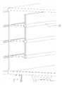
도 1은 본 발명에 따른 선반 확장 구조를 나타내는 대표 사시도.
도 2는 외측형 스토퍼가 구비된 선반 확장 구조를 나타낸 사시도.
도 3은 내측형 스토퍼가 구비된 선반 확장 구조를 나타낸 사시도.
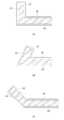
도 4 및 5는 보강대가 구비된 선반 확장 구조를 나타낸 사시도.
도 6은 축설부재가 구비된 선반 확장 구조를 나타낸 사시도.
도 7은 각 실시예 별 가이드와 선반의 측단면도.
도 8은 탈락방지홈 및 탈락방지로드가 추가된 가이드 및 선반의 측단면도.
도 9는 각 실시예 별 보강대의 측단면도.1 is a representative perspective view showing a shelf expansion structure according to the present invention.
Figure 2 is a perspective view showing a shelf expansion structure provided with an outer stopper.
Figure 3 is a perspective view showing a shelf expansion structure provided with an inner stopper.
4 and 5 are perspective views showing a shelf extension structure provided with a reinforcing bar.
Figure 6 is a perspective view showing a shelf expansion structure provided with a axial member.
7 is a side cross-sectional view of a guide and a shelf for each embodiment.
8 is a side cross-sectional view of a guide and a shelf to which a drop-off prevention groove and a drop-off prevention rod are added.
9 is a side cross-sectional view of a reinforcing bar for each embodiment.
본 발명은 다양한 변경을 가할 수 있고 여러 가지 형태를 가질 수 있는 바, 구현예(態樣, aspect)(또는 실시예)들을 본문에 상세하게 설명하고자 한다. 그러나 이는 본 발명을 특정한 개시 형태에 대해 한정하려는 것이 아니며, 본 발명의 사상 및 기술범위에 포함되는 모든 변경, 균등물 내지 대체물을 포함하는 것으로 이해되어야 한다.The present invention is intended to be described in detail in the text of the embodiment (態樣, aspect) (or embodiments) can be applied to various changes and can have various forms. However, this is not intended to limit the present invention to the specific disclosed form, it should be understood to include all modifications, equivalents and substitutes included in the spirit and scope of the present invention.
본 명세서에서 사용한 용어는 단지 특정한 구현예(태양, 態樣, aspect)(또는 실시예)를 설명하기 위해 사용된 것으로, 본 발명을 한정하려는 의도가 아니다. 단수의 표현은 문맥상 명백하게 다르게 뜻하지 않는 한, 복수의 표현을 포함한다. 본 출원에서, ~포함하다~ 또는 ~이루어진다~ 등의 용어는 명세서 상에 기재된 특징, 숫자, 단계, 동작, 구성요소, 부분품 또는 이들을 조합한 것이 존재함을 지정하려는 것이지, 하나 또는 그 이상의 다른 특징들이나 숫자, 단계, 동작, 구성요소, 부분품 또는 이들을 조합한 것들의 존재 또는 부가 가능성을 미리 배제하지 않는 것으로 이해되어야 한다.The terminology used herein is only used to describe a specific embodiment (aspect, aspect, aspect) (or embodiment), and is not intended to limit the present invention. The singular expression includes the plural expression unless the context clearly dictates otherwise. In the present application, terms such as comprises or consists of are intended to designate that the features, numbers, steps, operations, components, parts, or combinations thereof described in the specification exist, but one or more other features It is to be understood that it does not preclude the possibility of the presence or addition of numbers, steps, operations, components, parts, or combinations thereof.
다르게 정의되지 않는 한, 기술적이거나 과학적인 용어를 포함해서 여기서 사용되는 모든 용어들은 본 발명이 속하는 기술 분야에서 통상의 지식을 가진 자에 의해 일반적으로 이해되는 것과 동일한 의미를 가지고 있다. 일반적으로 사용되는 사전에 정의되어 있는 것과 같은 용어들은 관련 기술의 문맥 상 가지는 의미와 일치하는 의미를 가지는 것으로 해석되어야 하며, 본 출원에서 명백하게 정의하지 않는 한, 이상적이거나 과도하게 형식적인 의미로 해석되지 않는다.Unless defined otherwise, all terms used herein, including technical and scientific terms, have the same meaning as commonly understood by one of ordinary skill in the art to which this invention belongs. Terms such as those defined in commonly used dictionaries should be interpreted as having a meaning consistent with the meaning in the context of the related art, and should not be interpreted in an ideal or excessively formal meaning unless explicitly defined in the present application. does not
본 명세서에서 기재한 ~제1~, ~제2~ 등은 서로 다른 구성 요소들임을 구분하기 위해서 지칭할 것일 뿐, 제조된 순서에 구애받지 않는 것이며, 발명의 상세한 설명과 청구범위에서 그 명칭이 일치하지 않을 수 있다.~1~, ~2~, etc. described in the present specification will be referred to only to distinguish that they are different components, and are not limited to the order of manufacture, and their names in the detailed description and claims of the invention are may not match.
본 발명은 택배 차량의 선반 확장 구조에 관한 것으로 보다 상세하게는 택배 차량의 수용공간에 물품을 올려놓는 선반(1)이 도어(2)의 개방 시에 수용공간의 내측벽(I1)의 가이드와 도어(2)의 가이드를 따라 슬라이드할 수 있도록 구성되어 상기 선반(1)에 안착되는 물품의 상/하차가 매우 편리한 택배 차량의 선반 확장 구조에 관한 것이다.The present invention relates to a shelf extension structure of a delivery vehicle, and more particularly, a shelf (1) on which an article is placed in the accommodation space of the delivery vehicle when the door (2) is opened. It is configured to slide along the guide of the door (2), and it relates to a shelf extension structure of a delivery vehicle, which is very convenient for loading/unloading articles seated on the shelf (1).
본 발명에 따른 택배 차량의 선반 확장 구조는 도 1에 도시된 바와 같이, 크게 선반(1), 도어(2), 제1가이드(3) 및 제2가이드(4)로 구성된다.As shown in FIG. 1 , the shelf extension structure of the delivery vehicle according to the present invention is largely composed of a
먼저 선반(1)에 대해 살펴보면, 택배 차량의 수용공간에의 내측벽(I1)에 구비되는 선반(1)은 물품이 안착될 수 있다. 예시적으로 상기 선반(1)은 도 1에 도시된 바와 같이 판상형으로 구성될 수 있다.First, looking at the
그 다음으로 도어(2)에 대해 살펴보면, 상기 도어(2)는 상기 택배 차량의 상기 수용공간을 개폐시킬 수 있으며, 자명하게도 상기 택배 차량의 컨테이너(C)와 경첩을 이용하여 결합된다.Next, looking at the
그 다음으로 제1가이드(3)와 제2가이드(4)에 대해 살펴보면, 상기 제1가이드(3)는 상기 내측벽(I1)에 구비되고 상기 선반(1)이 이동하는 경로를 제공하고, 상기 제2가이드(4)는 상기 도어(2)의 내측면(I2)에 구비되고, 상기 제1가이드(3)와 동일 높이에 구비되어 상기 도어(2)의 개방 시에 상기 제1가이드(3)와 연결되도록 구성된다.Next, looking at the
상기 제1가이드(3)와 제2가이드(4)의 구성의 핵심 특징은 서로 동일한 높이에 구비된다는 것이다. 왜냐하면 이들이 동일 높이에 구비되어 있지 아니한 경우에는 상기 선반(1)이 상기 제1가이드(3) 및 제2가이드(4)를 따라 이동할 수 없기 때문이다.A key feature of the configuration of the
그리고 상기 제1가이드(3)와 제2가이드(4)에 대한 일 실시예를 살펴보기로 한다.In addition, an embodiment of the
상기 제1가이드(3)와 제2가이드(4)의 일 실시예로서, 상기 제1가이드(3) 및 제2가이드(4)는 가이드홈(G)으로 구성될 수 있다. 그리고 여기서 가이드홈(G)으로 구성됨에 따라 상기 선반(1)은 상기 가이드홈(G)에 삽입되는 구조를 띄게 된다.As an embodiment of the
그리고 상기 일 실시예를 더욱 구체적으로 살펴보면, 상기 가이드홈(G)은 상기 선반(1)의 이동 방향에 평행한 수평홈(G1) 및, 상기 수평홈(G1)의 단부에 연결되고 상기 수평홈(G1)에 수직한 수직홈(G2)을 포함할 수 있다.And looking at the embodiment in more detail, the guide groove (G) is connected to the horizontal groove (G1) parallel to the moving direction of the shelf (1) and the end of the horizontal groove (G1), the horizontal groove It may include a vertical groove (G2) perpendicular to (G1).
여기서 상기 수평홈(G1)에 수직한 수직홈(G2)이라고 기재하였지만 도 7에 도시된 바와 같이, 상기 수평홈(G1)과 수직홈(G2)이 이루는 각이 예각 또는 둔각으로 구성될 수도 있다.Here, although described as a vertical groove (G2) perpendicular to the horizontal groove (G1), as shown in FIG. 7, the angle between the horizontal groove (G1) and the vertical groove (G2) may be configured as an acute angle or an obtuse angle. .
이처럼 직각이 아닌 예각으로 구성되는 경우에는 상기 선반(1)의 안착면에 안착되는 물품들에 의해 상기 선반(1)의 안착면에 수직으로 작용하는 힘에 대응하는 대응력 확보에 더 유리하다는 장점을 가질 수 있게 된다. 그러나 직각에 비하여 둔각 또는 예각의 경우에는 제조가 더 난해하다는 단점을 갖게 된다.As such, when it is configured at an acute angle instead of a right angle, it is more advantageous to secure a corresponding force corresponding to a force perpendicular to the seating surface of the
그리고 상기 가이드홈(G)에 삽입될 수 있도록 상기 선반(1)은 일 측면에 상기 가이드홈(G)에 슬라이드 결합되는 결합대응부(11)를 포함한다.And the
그리고 상기 결합대응부(11)는 상기 수평홈(G1)에 나란하게 배치되는 수평대응부(111), 그리고 상기 수평대응부(111)의 단부에서 이어지되 상기 수직홈(G2)에 나란하게 배치되는 수직대응부(112)를 포함한다.And the coupling corresponding portion 11 is a horizontal
여기서 나란하게 배치된다는 말의 의미는 상기 수평홈(G1)의 크기, 깊이, 높이와 상기 수평대응부(111)의 그것가 서로 일치하여 끼움 결합이 실현된 상태를 말한다. 물론 수직홈(G2)과 수직대응부(112) 또한 마찬가지이다.Here, the meaning of being arranged side by side refers to a state in which the size, depth, and height of the horizontal groove G1 and that of the
그리고 상기 수평홈(G1) 및 수직홈(G2)이 서로 예각 또는 둔각을 형성하는 경우에도 역시 상기 수평대응부(111)는 상기 수평홈(G1)에 끼움 결합이 실현되고, 상기 수직대응부(112) 또한 상기 수직홈(G2)에 끼움 결합이 실현되도록 구비된다.And even when the horizontal groove (G1) and the vertical groove (G2) form an acute or obtuse angle with each other, the
그리고 도 8에 도시된 바와 같이, 상기 가이드홈(G)은 상기 수직홈(G2) 또는 수평홈(G1)의 일면에 상기 수직홈(G2) 또는 수평홈(G1)과 연결되되, 원통형상을 갖는 탈락방지홈(G3)을 더 포함할 수 있다.And as shown in Figure 8, the guide groove (G) is connected to the vertical groove (G2) or the horizontal groove (G1) on one surface of the vertical groove (G2) or the horizontal groove (G1), the cylindrical shape It may further include a drop-off prevention groove (G3) having.
여기서 상기 수직홈(G2) 또는 수평홈(G1)의 일면은 상기 수직홈(G2) 또는 수평홈(G1)의 상부, 내측면(I2) 또는 외측면이 될 수 있다.Here, one surface of the vertical groove G2 or the horizontal groove G1 may be an upper, inner surface I2 or an outer surface of the vertical groove G2 or the horizontal groove G1.
그리고 상기 탈락방지홈(G3)의 단면의 형태가 상기 수직홈(G2)이나 수평홈(G1)의 단면과 같이 사각형의 형태가 아닌 원형으로 구비될 수 있고, 아울러서 상기 수직홈(G2)이나 수평홈(G1)의 크기보다 작게 구비될 수 있다.And the cross-sectional shape of the drop-off preventing groove (G3) may be provided in a circular shape instead of a rectangular shape like the cross section of the vertical groove (G2) or the horizontal groove (G1), and at the same time, the vertical groove (G2) or the horizontal groove (G1). It may be provided smaller than the size of the groove G1.
도 8에 도시된 바와 같이, 상기 탈락방지홈(G3)의 직경은 상기 수직홈(G2)의 폭보다 절반 이하를 갖도록 구성될 수 있다.As shown in Figure 8, the diameter of the drop-off preventing groove (G3) may be configured to have less than half the width of the vertical groove (G2).
상기 탈락방지홈(G3)의 형상과 크기가 전술한 바와 같이 구성되는 경우에는 상기 수직홈(G2)과 수평홈(G1)에 의해서만 상기 선반(1)이 가이드될 때보다 상기 선반(1)의 미세한 움직임에 대한 가이드를 효과적으로 수행할 수 있어 상기 선반(1)의 매끄러운 이동을 실현할 수 있게 된다.When the shape and size of the drop-off preventing groove (G3) is configured as described above, the shelf (1) is higher than when the shelf (1) is guided only by the vertical groove (G2) and the horizontal groove (G1). It is possible to effectively guide the fine movement, so that it is possible to realize the smooth movement of the
일 실시예로 도 8의 [A]에 도시된 바와 같이, 상기 탈락방지홈(G3)은 상기 수직홈(G2)의 상부의 내측에 구비될 수 있다.In one embodiment, as shown in [A] of Figure 8, the drop-off prevention groove (G3) may be provided inside the upper portion of the vertical groove (G2).
그리고 일 실시예로, 상기 탈락방지홈(G3)은 상기 수평홈(G1)의 상부의 내측에 구비될 수 있다.And in one embodiment, the drop-off preventing groove (G3) may be provided inside the upper portion of the horizontal groove (G1).
그리고 일 실시예로, 상기 탈락방지홈(G3)은 상기 수직홈(G2)의 상부의 내측 및 상기 수평홈(G1)의 상부의 내측 모두에 구비될 수 있다.And in one embodiment, the drop-off prevention groove (G3) may be provided on both the inner side of the upper portion of the vertical groove (G2) and the inner side of the upper portion of the horizontal groove (G1).
여기서 내측에 구비됨으로서 획득할 수 있는 효과로는 외측에 구비될 때보다 상기 물품에 의한 상기 선반(1)의 안착면 상에 작용하는 휨 모멘트에 의한 저항력을 더 크게 확보할 수 있게 된다.Here, as an effect that can be obtained by being provided on the inside, it is possible to secure a greater resistance force due to a bending moment acting on the seating surface of the
그리고 상기 수직홈(G2) 및 수평홈(G1)이 이루는 각도가 예각을 이루는 경우에는 상기 탈락방지홈(G3)이 상기 수직홈(G2)의 외측면의 상부에 구비되어 실시될 수도 있는데, 상기 예각에 의해 상기 수직홈(G2)이 수직으로 배치될 때보다 내측으로 치우쳐져 있으므로, 그와 반대되는 방향에 상기 탈락방지홈(G3)이 배치되어 가이드의 균형을 맞출 수 있다는 효과를 획득할 수 있게 된다.And when the angle formed by the vertical groove G2 and the horizontal groove G1 forms an acute angle, the drop-off prevention groove G3 may be provided on the outer surface of the vertical groove G2 and may be implemented. Because the vertical groove (G2) is inclined inward than when it is vertically arranged by an acute angle, the drop-off prevention groove (G3) is arranged in the opposite direction to achieve the effect of balancing the guide there will be
그리고 예시적으로 도 8의 [B]에 도시된 바와 같이, 상기 수직홈(G2)과 수평홈(G1)이 연결되는 부분의 내측면에 각도가 형성되는 지점에 상기 탈락방지홈(G3)이 구비될 수 있다. 이 때의 장점으로는 접혀지는 부위를 상기 수직홈(G2) 및 수평홈(G1)의 단면의 모양, 크기가 다른 탈락방지홈(G3)이 가이드시킴으로서 가이드의 안정성을 향상시킬 수 있다는 장점이 존재하게 된다.And illustratively, as shown in [B] of Figure 8, the drop-off prevention groove (G3) at the point where an angle is formed on the inner surface of the portion where the vertical groove (G2) and the horizontal groove (G1) are connected. can be provided. As an advantage at this time, there is an advantage that the stability of the guide can be improved by guiding the folded portion by the drop-off prevention grooves G3 having different cross-sectional shapes and sizes of the vertical grooves G2 and the horizontal grooves G1. will do
그리고 도 8에 도시된 바와 같이, 상기한 탈락방지홈(G3)의 구비에 따라 상기 선반(1)은, 상기 탈락방지홈(G3)이 구비되는 위치와 상응하는 위치에 상기 탈락방지홈(G3)의 크기와 상응하는 크기를 갖되, 상기 수평대응부(111) 또는 수직대응부(112)에 연결되는 탈락방지로드(113)를 구비하게 된다.And, as shown in FIG. 8 , according to the provision of the drop-off prevention groove G3, the
여기서 상응하는 위치라고 함은 실시예에 따라 각기 다른 위치에 구비되는 탈락방지홈(G3)의 위치에 대응되는 곳에 상기 탈락방지로드(113)가 구비되는 것을 말하며, 상응하는 크기라고 함은 끼움 결합이 실현될 수 있도록 그에 대응되는 크기를 갖는 것을 말한다.Here, the corresponding position means that the drop-
그 다음으로 도 4에 도시된 바와 같이, 상기 도어(2)의 하부에는 보강대(5)가 결합될 수 있다. 상기 도어(2)의 개방 시에 상기 선반(1)이 상기 도어(2)의 내측면(I2)에 구비되는 제2가이드(4)를 따라 가이드될 때, 상기 선반(1) 및 상기 선반(1)의 안착면에 안착된 물품의 무게에 의해 상기 도어(2)가 하부로 무너지는 것을 방지하는 구성에 해당된다.Next, as shown in FIG. 4 , a reinforcing
그리고 이에 부대하는 효과로는 상기 제1가이드(3) 및 제2가이드(4)의 높이를 동일하게 유지시키는 것을 들 수 있다.In addition, as an effect incident thereto, the height of the
상기 보강대(5)는 상기 도어(2)의 하면에 결합하는 결합부재(51), 그리고 상기 결합부재(51)에 회동결합하는 지지바(52), 그리고 상기 지지바(52)의 단부에 결합되어 지지면과 접촉하는 접촉부재(53)를 포함한다.The reinforcing
상기 결합부재(51)와 상기 지지바(52)가 회동 결합함에 따라 도어(2)의 폐쇄 시에는 상기 보강대(5)를 접어서 보관시킬 수 있게 되어 이들 구비에 따른 공간 제약을 덜 수 있다는 장점이 존재한다. 그리고 예시적으로 상기 보강대(5)가 접힘으로써 상기 지지바(52)의 일면은 상기 도어(2)의 하면과 접촉하게 되는데, 이러한 지지바접촉면과 상기 도어(2)의 하면에 자석을 구비하여 상기 보강대(5)가 상기 도어(2)로부터 이탈되는 것을 방지할 수 있다.As the
또한 예시적으로 상기 결합부재(51)가 도어(2) 측으로 접혀졌을 때, 안정적으로 도어(2)와 접촉을 이룰 수 있도록 상기 도어(2)의 하면은 상기 보강대(5)의 형상에 상응하는 형상을 갖는 보관홈을 구비할 수 있다. 여기서 상응하는 형상이라고 함은 상기 보관홈에 상기 보강대(5)가 끼워질 수 있도록 크기, 위치 등이 서로 대응되는 것을 의미한다. 물론, 상기 도어(2)의 하면에 자성체의 구비 시에는 상기 보관홈의 표면에 구비될 것이다.Also, for example, when the
그리고 상기 지지바(52)는 높이조절수단을 구비할 수 있다. 이에 상기 지지바(52)의 길이를 가변적으로 조절할 수 있으므로 상기 택배 차량이 언덕에 위치하여 기울어져 있을 때에도 상기 도어(2)를 지지시킬 수 있게 된다.And the
상기 높이조절수단의 일 실시예로서 레버가 달린 QR레버 클램프가 구비될 수 있다. 따라서 작업자는 상황에 따라 상기 레버를 당겨 고정을 해제함으로써 상기 지지대의 높이를 간편하게 조절할 수 있게 된다.As an embodiment of the height adjusting means, a QR lever clamp with a lever may be provided. Accordingly, the operator can easily adjust the height of the support by pulling the lever to release the fixing according to the situation.
그리고 도 5에 도시된 바와 같이, 상기 선반(1)의 하부에는 상기 보강대(5)가 결합되고, 상기 보강대(5)는 상기 선반(1)의 하면에 결합하는 결합부재(51), 상기 결합부재(51)에 회동 결합하는 지지바(52) 및 상기 지지바(52)의 단부에 결합되어 지지면과 접촉하는 접촉부재(53)를 포함한다.And as shown in FIG. 5 , the reinforcing
그리고 상기 접촉부재(53)는 도 9에 도시된 바와 같이, 두 가지 형태의 실시예를 가질 수 있다.In addition, the
일 실시예로 도 9의 [A]에 도시된 바와 같이, 상기 접촉부재(53)는 바퀴로 구성될 수 있다.In one embodiment, as shown in [A] of FIG. 9, the
이처럼 바퀴로 구성되는 경우에는 접혀있는 지지바(52)를 지지면 측으로 빼내어 지지면과 상기 접촉부재(53)가 접촉되는 지점부터 지지되는 지점까지 회동시키는 데에 작업자의 부담을 덜 수 있다는 장점이 존재하게 된다.The advantage of reducing the burden on the operator in that the folded
아울러서, 상기 선반(1)의 하부에 상기 보강대(5)가 결합되는 경우에는 상기 접촉부재(53)가 바퀴로 구성되어 보강대(5)를 기준으로 상부에 위치하는 선반(1)을 이동시킬 때 바퀴에 의해 상부 선반(1)들 편리하게 이동시킬 수 있다는 장점이 존재하게 된다.In addition, when the reinforcing
그리고 또 다른 실시예로 도 9의 [B]에 도시된 바와 같이, 상기 접촉부재(53)는 직육면체 형상을 갖는 부재로 구성될 수 있다. 상기 직육면체 형상의 부재는 마찰력이 높은 고무 소재 등으로 구성될 수 있다. 이 실시예의 경우에는 지지면과의 마찰력을 극대화시켜 안정적인 지지를 수행할 수 있다는 장점을 갖게 된다.And as another embodiment, as shown in [B] of Figure 9, the
따라서 일 실시예로 상기 도어(2)의 하부에 결합되는 보강대(5)의 접촉부재(53)와, 상기 선반(1)의 하부에 결합되는 보강대(5)의 접촉부재(53)가 모두 바퀴로 구성될 수 있다.Therefore, in one embodiment, both the
또는 일 실시예로 도어(2)의 하부에 결합되는 보강대(5)의 접촉부재(53)는 고무 재질의 직육면체 형상을 갖는 부재로 구성되고, 상기 선반(1)의 하부에 결합되는 보강대(5)의 접촉부재(53)는 바퀴로 구성될 수 있다.Alternatively, in one embodiment, the
그 다음으로 상기 선반(1)의 이동을 제한하는 스토퍼를 더 포함할 수 있다.Next, it may further include a stopper for limiting the movement of the shelf (1).
상기 스토퍼의 경우에는 상기 수용공간을 기준으로 하여 구비되는 위치에 따라 두가지의 실시예로 구성될 수 있으며, 첫 번째 실시예는 상기 수용공간의 외부에 구비되는 외측형 스토퍼(6A)이고, 두 번째 실시예는 상기 수용공간의 내부에 구비되는 내측형 스토퍼(6B)이다.In the case of the stopper, it may be configured in two embodiments depending on the position provided with respect to the accommodation space. The first embodiment is an
먼저 첫 번째 실시예에 해당하는 외측형 스토퍼(6A)의 경우에는 도 2에 도시된 바와 같이, 상기 도어(2)의 상기 내측면(I2)의 단부에 구비되되, 상기 제2가이드(4)를 제한할 수 있는 높이에 구비된다.First, in the case of the outer-
그리하여 상기 선반(1)의 이동 변위가 상기 제2가이드(4)의 길이만큼 제한되면서 상기 선반(1)을 스토핑시키게 된다. 즉, 상기 외측형 스토퍼(6A)와 상기 선반(1)의 전면이 맞닿으면서 상기 선반(1)이 스토핑되는 것이다.Thus, the
그리고 여기서 상기 내측면(I2)의 단부라고 함은 상기 선반(1)의 이동 방향을 기준으로 하였을 때의 끝단을 의미하는 것이며, 제한할 수 있는 높이라고 함은 상기 외측형 스토퍼(6A)가 높이 방향을 기준으로 상기 제2가이드(4)를 밀폐시킬 수 있는 높이를 가짐을 의미한다.And here, the end of the inner surface I2 refers to the end when the moving direction of the
그리고 상기 외측형 스토퍼(6A)의 경우에는 상기 선반(1)의 이동 변위가 제2가이드(4)의 길이만큼으로 제한된다는 단점이 분명 존재하지만 오히려 무거운 물품을 싣고 있는 선반(1)의 경우에는 선반(1)이 상기 제2가이드(4)의 길이보다 더 길게 외측으로 빠지는 경우에는 무너질 염려가 있기 때문에 이를 미연에 방지하는 효과를 가지게 된다.And in the case of the
아울러, 후술하겠지만 상기 내측형 스토퍼(6B)와 비교하였을 때, 상기 외측형 스토퍼(6A)는 상기 내측면(I2)의 단부에 구비됨에 따라 상기 물품이 수용되는 수용공간을 침범하지 아니하기 때문에 상기 물품의 수용성을 해치지 않을 수 있다는 장점을 갖게 된다.In addition, as will be described later, compared with the
그리고 상기 스토퍼의 접촉면과 상기 선반(1)의 전면에는 자석을 구비하여 상기 선반(1)이 상기 선반(1)의 이동 변위를 제한하는 지점 근처에 위치하였을 때 반자동으로 상기 선반(1)을 스토핑시키는 효과를 획득할 수 있다.And a magnet is provided on the contact surface of the stopper and the front surface of the
그리고 또 다른 실시예로 상기 스토퍼의 접촉면 및 상기 선반(1)의 전면에 자석을 중앙에 구비시키고, 상기 자석의 주변은 고무 패킹을 하여 반자동 스토핑 기능뿐만 아니라 스토핑의 안정성 또한 확보할 수도 있다.And in another embodiment, a magnet is provided in the center on the contact surface of the stopper and the front surface of the
그 다음으로 두 번째 실시예에 해당하는 내측형 스토퍼(6B)의 경우에는 도 3에 도시된 바와 같이, 상기 수용공간의 상기 내측벽(I1)의 단부에 구비되는 걸림부재(61B), 그리고 상기 선반(1)의 안착면과 상기 수용공간의 내측벽(I1)에 결합하여 이어지게 구비되도록'ㄱ'자 형상을 가지는 피걸림부재(62B)를 포함한다.Next, in the case of the
그리고 상기 피걸림부재(62B)와 내측벽(I1)과의 결합은 슬라이딩 결합되고, 상기 피걸림부재(62B)와 안착면과의 결합은 일반적인 고정 결합이 이루어지게 된다.And the coupling between the caught
그리고 상기 내측형 스토퍼(6B)의 경우에는 상기 걸림부재(61B)와 피걸림부재(62B) 간의 거리에 따라 상기 선반(1)의 이동 변위가 달라질 수 있는데, 예시적으로 도 3에 도시된 바와 같이, 상기 걸림부재(61B)와 걸림대응부 간의 거리는 상기 제2가이드(4)의 길이의 절반 정도에 해당하는 거리를 갖도록 구성시킬 수 있다. 물론 여기서 상기 걸림부재(61B)와 피걸림부재(62B) 간의 거리는 선반(1)의 몸체 전부가 수용공간에 위치하는 최초 상태일 때의 거리를 말하는 것이다.And in the case of the
이에 따라 선반(1)의 몸체 전부가 전부 이동하는 최종 상태일 때의 거리는 제2가이드(4)의 길이에 더하여 상기 걸림부재(61B)와 피걸림부재(62B) 간의 거리까지로 확장될 수 있는 것이다.Accordingly, the distance in the final state in which the entire body of the
그리하여 선반(1)의 이동 변위를 외측형 스토퍼(6A)에 비하여 더 길게 가져갈 수 있다. 그러나 전술하였듯이 단점으로는, 선반(1)의 안착면에 위치하는 물품들의 무게가 무거운 경우에는 상기 선반(1)의 최종 상태가 과도하게 바깥으로 돌출되어 상기 선반(1)이 무너질 위험이 존재한다는 것이다.Thus, the movement displacement of the
따라서 본 발명은 상기 외측형 스토퍼(6A) 및 내측형 스토퍼(6B)의 장점을 모두 살리기 위해서 상기 외측형 스토퍼(6A) 및 내측형 스토퍼(6B)를 상기 선반(1)의 층별로 다르게 구비시킬 수도 있다.Therefore, in the present invention, in order to take advantage of both the advantages of the
예시적으로 1층 선반(1)에는 외측형 스토퍼(6A)를 구비시키고, 2층 선반(1)에는 내측형 스토퍼(6B)를 구비시켜 2층 선반(1)을 1층 선반(1)보다 수용공간 바깥으로 더 길게 빼낼 수 있게 구성시킬 수 있고, 아울러 1층 선반(1)에는 상대적으로 무거운 물품을 구비시켜 선반(1)의 층별로 공간 활용을 효과적으로 수행할 수 있다는 장점이 존재하게 된다.Exemplarily, the first-
그 다음으로 상기 선반(1)은 상기 선반(1)의 일부가 접힐 수 있도록 상기 선반(1)의 길이 방향을 따라 축설부재(12)가 구비될 수 있다. 도 6에 도시된 바와 같이, 상기 선반(1)은 상기 축설부재(12)를 기준으로 접힐 수 있게 된다.Next, the
상기 선반(1)을 접은 경우에는 물품이 상기 안착면으로부터 떨어지는 것을 방지할 수 있고, 또한 수용공간(A)의 공간 활용을 수행할 수 있다는 장점을 갖게 된다.When the
이상에서 첨부된 도면을 참조하여 설명한 본 발명은 통상의 기술자에 의하여 다양한 변형 및 변경이 가능하고, 이러한 변형 및 변경은 본 발명의 권리범위에 포함되는 것으로 해석되어야 한다.The present invention described above with reference to the accompanying drawings is capable of various modifications and changes by those skilled in the art, and such modifications and changes should be construed as being included in the scope of the present invention.
1: 선반 11: 결합대응부
111: 수평대응부 112: 수직대응부
113: 탈락방지로드 12: 축설부재
2: 도어
3: 제1가이드 G: 가이드홈
G1: 수평홈 G2: 수직홈
G3: 탈락방지홈
4: 제2가이드
5: 보강대 51: 결합부재
52: 지지바 53: 접촉부재
6A: 외측형 스토퍼 6B: 내측형 스토퍼1: shelf 11: mating part
111: horizontal correspondence part 112: vertical correspondence part
113: drop-off prevention rod 12: axial member
2: Door
3: first guide G: guide groove
G1: Horizontal groove G2: Vertical groove
G3: Drop-off prevention groove
4: Second guide
5: reinforcing bar 51: coupling member
52: support bar 53: contact member
6A: Outside
Claims (6)
Translated fromKorean상기 수용공간을 개폐하는 도어;
상기 내측벽에 구비되고 상기 선반이 이동하는 경로를 제공하는 제1가이드; 및
상기 도어의 내측면에 구비되고, 상기 제1가이드와 동일 높이에 구비되어 상기 도어의 개방 시에 상기 제1가이드와 연결되는 제2가이드;를 포함하고,
상기 제1가이드 및 제2가이드는 가이드홈으로 구성되며, 상기 가이드홈은 상기 가이드홈은 상기 선반의 이동 방향에 평행한 수평홈 및, 상기 수평홈의 단부에 연결되고 상기 수평홈에 수직한 수직홈을 포함하고,
상기 선반은 일 측면에 상기 가이드홈에 슬라이드 결합되는 결합대응부를 포함하되,
상기 결합대응부는 상기 수평홈에 나란하게 배치되는 수평대응부 및, 상기 수평대응부의 단부에서 이어지되 상기 수직홈에 나란하게 배치되는 수직대응부를 포함하고,
상기 가이드홈은 상기 선반의 이동방향에 평행한 수평홈 및 상기 수평홈에 수직한 수직홈을 포함하고,
상기 선반은 상기 선반의 길이 방향을 따라 상기 선반의 일부를 접을 수 있는 축설부재를 포함하고,
상기 도어의 하부에는 보강대가 결합되고, 상기 보강대는 상기 도어의 하면에 결합하는 결합부재, 상기 결합부재에 회동 결합하는 지지바 및 상기 지지바의 단부에 결합되어 지지면과 접촉하는 접촉부재를 포함하는 택배 차량의 선반 확장 구조.
a shelf provided on the inner wall of the accommodation space;
a door for opening and closing the accommodation space;
a first guide provided on the inner wall and providing a path for the shelf to move; and
a second guide provided on the inner surface of the door, provided at the same height as the first guide, and connected to the first guide when the door is opened; and
The first guide and the second guide are composed of guide grooves, wherein the guide groove includes a horizontal groove parallel to the moving direction of the shelf, and a vertical groove connected to an end of the horizontal groove and perpendicular to the horizontal groove. including home;
The shelf includes a coupling corresponding portion that is slide-coupled to the guide groove on one side,
The coupling corresponding portion includes a horizontal corresponding portion disposed in parallel to the horizontal groove, and a vertical corresponding portion extending from the end of the horizontal corresponding portion and disposed parallel to the vertical groove,
The guide groove includes a horizontal groove parallel to the moving direction of the shelf and a vertical groove perpendicular to the horizontal groove,
The shelf includes a axial member capable of folding a part of the shelf along the longitudinal direction of the shelf,
A reinforcing bar is coupled to the lower portion of the door, and the reinforcing bar includes a coupling member coupled to the lower surface of the door, a support bar pivotally coupled to the coupling member, and a contact member coupled to an end of the support bar to contact the support surface. Shelf extension structure of a courier vehicle that does
상기 수평홈 및 상기 수직홈이 이루는 각도와 상기 수평대응부 및 상기 수직대응부가 이루는 각도는 서로 예각을 형성하는 것을 특징으로 하는
는 택배 차량의 선반 확장 구조.
The method according to claim 1,
An angle formed by the horizontal groove and the vertical groove and an angle formed by the horizontal corresponding portion and the vertical corresponding portion form an acute angle with each other
is a shelf extension structure of a courier vehicle.
상기 수평홈 및 상기 수직홈이 이루는 각도와 상기 수평대응부 및 상기 수직대응부가 이루는 각도는 서로 둔각을 형성하는 것을 특징으로 하는
The method according to claim 1,
An angle formed by the horizontal groove and the vertical groove and an angle formed by the horizontal corresponding portion and the vertical corresponding portion form an obtuse angle with each other
상기 선반의 하부에는 상기 보강대가 결합되고,
상기 보강대는 상기 선반의 하면에 결합하는 결합부재, 상기 결합부재에 회동 결합하는 지지바 및 상기 지지바의 단부에 결합되어 지지면과 접촉하는 접촉부재를 포함하는 것을 특징으로 하는 택배 차량의 선반 확장 구조.The method according to claim 1,
The reinforcing bar is coupled to the lower part of the shelf,
The reinforcing bar includes a coupling member coupled to a lower surface of the shelf, a support bar pivotally coupled to the coupling member, and a contact member coupled to an end of the support bar to contact the support surface. structure.
Applications Claiming Priority (2)
| Application Number | Priority Date | Filing Date | Title |
|---|---|---|---|
| KR1020200133813 | 2020-10-15 | ||
| KR20200133813 | 2020-10-15 |
Publications (1)
| Publication Number | Publication Date |
|---|---|
| KR102324031B1true KR102324031B1 (en) | 2021-11-09 |
Family
ID=78610333
Family Applications (1)
| Application Number | Title | Priority Date | Filing Date |
|---|---|---|---|
| KR1020210040841AActiveKR102324031B1 (en) | 2020-10-15 | 2021-03-30 | Extended shelf structure |
Country Status (1)
| Country | Link |
|---|---|
| KR (1) | KR102324031B1 (en) |
Citations (2)
| Publication number | Priority date | Publication date | Assignee | Title |
|---|---|---|---|---|
| KR101231870B1 (en)* | 2012-08-23 | 2013-02-08 | (주)한영Fa산업 | Mold loading apparatus |
| US20200198515A1 (en)* | 2018-12-19 | 2020-06-25 | Spartan Motors, Inc. | Vehicle Conveyor System |
- 2021
- 2021-03-30KRKR1020210040841Apatent/KR102324031B1/enactiveActive
Patent Citations (2)
| Publication number | Priority date | Publication date | Assignee | Title |
|---|---|---|---|---|
| KR101231870B1 (en)* | 2012-08-23 | 2013-02-08 | (주)한영Fa산업 | Mold loading apparatus |
| US20200198515A1 (en)* | 2018-12-19 | 2020-06-25 | Spartan Motors, Inc. | Vehicle Conveyor System |
Similar Documents
| Publication | Publication Date | Title |
|---|---|---|
| US8162190B2 (en) | Ergonomic lift mechanism for a truck box | |
| RU2017101171A (en) | DEVICE FOR LOADING AND UNLOADING BOXES FROM A LOAD VEHICLE | |
| US8844996B2 (en) | Extendable bed assembly for a vehicle | |
| JP7453380B2 (en) | Guide device, furniture and method for guiding at least one movable furniture part | |
| KR102324031B1 (en) | Extended shelf structure | |
| KR20210004467A (en) | Rail structure to preventing droop of pick-up truck drawer cargo box or sliding bed | |
| KR101142245B1 (en) | Sliding carrier in a vehicle | |
| US20040140305A1 (en) | Storage box | |
| US20250009091A1 (en) | Rolling Modular Storage Unit with Drawers | |
| CN108791091B (en) | Cargo compartment components for motor vehicles | |
| US10449906B2 (en) | Storage cabinet for use in a vehicle | |
| KR102308217B1 (en) | A box truck with a shielding device | |
| US8075239B2 (en) | Cargo handling device for vehicle | |
| KR101796246B1 (en) | Door opening and shutting structure of wingbody truck | |
| KR102340347B1 (en) | Awning of storage type for truck | |
| US20190225133A1 (en) | Vehicle, in particular emergency vehicle, with a loading arrangement | |
| CA2722106A1 (en) | Freight container with doors | |
| KR101653396B1 (en) | Container for carrying bulk cargo | |
| KR100747888B1 (en) | Floor panel structure of luggage room of vehicle | |
| JP3391323B2 (en) | Opening and closing structure of a cargo box | |
| KR100863178B1 (en) | Car Luggage Box | |
| KR102597634B1 (en) | Loading module for vehicle | |
| KR102362181B1 (en) | The Tool Box for Truck Cargo Box | |
| KR100428451B1 (en) | A flexible Guide for protecting a cargo of a cargo box | |
| KR102025383B1 (en) | Container |
Legal Events
| Date | Code | Title | Description |
|---|---|---|---|
| PA0109 | Patent application | St.27 status event code:A-0-1-A10-A12-nap-PA0109 | |
| PA0201 | Request for examination | St.27 status event code:A-1-2-D10-D11-exm-PA0201 | |
| PA0302 | Request for accelerated examination | St.27 status event code:A-1-2-D10-D17-exm-PA0302 St.27 status event code:A-1-2-D10-D16-exm-PA0302 | |
| D13-X000 | Search requested | St.27 status event code:A-1-2-D10-D13-srh-X000 | |
| D14-X000 | Search report completed | St.27 status event code:A-1-2-D10-D14-srh-X000 | |
| PE0902 | Notice of grounds for rejection | St.27 status event code:A-1-2-D10-D21-exm-PE0902 | |
| E13-X000 | Pre-grant limitation requested | St.27 status event code:A-2-3-E10-E13-lim-X000 | |
| P11-X000 | Amendment of application requested | St.27 status event code:A-2-2-P10-P11-nap-X000 | |
| P13-X000 | Application amended | St.27 status event code:A-2-2-P10-P13-nap-X000 | |
| E701 | Decision to grant or registration of patent right | ||
| PE0701 | Decision of registration | St.27 status event code:A-1-2-D10-D22-exm-PE0701 | |
| GRNT | Written decision to grant | ||
| PR0701 | Registration of establishment | St.27 status event code:A-2-4-F10-F11-exm-PR0701 | |
| PR1002 | Payment of registration fee | St.27 status event code:A-2-2-U10-U11-oth-PR1002 Fee payment year number:1 | |
| PG1601 | Publication of registration | St.27 status event code:A-4-4-Q10-Q13-nap-PG1601 | |
| R18-X000 | Changes to party contact information recorded | St.27 status event code:A-5-5-R10-R18-oth-X000 | |
| PR1001 | Payment of annual fee | St.27 status event code:A-4-4-U10-U11-oth-PR1001 Fee payment year number:4 | |
| PR1001 | Payment of annual fee | St.27 status event code:A-4-4-U10-U11-oth-PR1001 Fee payment year number:5 |