KR102323418B1 - Led lighting apparatus improved heat radiation property - Google Patents
Led lighting apparatus improved heat radiation propertyDownload PDFInfo
- Publication number
- KR102323418B1 KR102323418B1KR1020140121777AKR20140121777AKR102323418B1KR 102323418 B1KR102323418 B1KR 102323418B1KR 1020140121777 AKR1020140121777 AKR 1020140121777AKR 20140121777 AKR20140121777 AKR 20140121777AKR 102323418 B1KR102323418 B1KR 102323418B1
- Authority
- KR
- South Korea
- Prior art keywords
- emitting diode
- light emitting
- lighting device
- driving unit
- disposed
- Prior art date
- Legal status (The legal status is an assumption and is not a legal conclusion. Google has not performed a legal analysis and makes no representation as to the accuracy of the status listed.)
- Active
Links
Images


Classifications
- F—MECHANICAL ENGINEERING; LIGHTING; HEATING; WEAPONS; BLASTING
- F21—LIGHTING
- F21K—NON-ELECTRIC LIGHT SOURCES USING LUMINESCENCE; LIGHT SOURCES USING ELECTROCHEMILUMINESCENCE; LIGHT SOURCES USING CHARGES OF COMBUSTIBLE MATERIAL; LIGHT SOURCES USING SEMICONDUCTOR DEVICES AS LIGHT-GENERATING ELEMENTS; LIGHT SOURCES NOT OTHERWISE PROVIDED FOR
- F21K9/00—Light sources using semiconductor devices as light-generating elements, e.g. using light-emitting diodes [LED] or lasers
- F—MECHANICAL ENGINEERING; LIGHTING; HEATING; WEAPONS; BLASTING
- F21—LIGHTING
- F21V—FUNCTIONAL FEATURES OR DETAILS OF LIGHTING DEVICES OR SYSTEMS THEREOF; STRUCTURAL COMBINATIONS OF LIGHTING DEVICES WITH OTHER ARTICLES, NOT OTHERWISE PROVIDED FOR
- F21V29/00—Protecting lighting devices from thermal damage; Cooling or heating arrangements specially adapted for lighting devices or systems
- F21V29/10—Arrangement of heat-generating components to reduce thermal damage, e.g. by distancing heat-generating components from other components to be protected
- F—MECHANICAL ENGINEERING; LIGHTING; HEATING; WEAPONS; BLASTING
- F21—LIGHTING
- F21V—FUNCTIONAL FEATURES OR DETAILS OF LIGHTING DEVICES OR SYSTEMS THEREOF; STRUCTURAL COMBINATIONS OF LIGHTING DEVICES WITH OTHER ARTICLES, NOT OTHERWISE PROVIDED FOR
- F21V19/00—Fastening of light sources or lamp holders
- F21V19/001—Fastening of light sources or lamp holders the light sources being semiconductors devices, e.g. LEDs
- F—MECHANICAL ENGINEERING; LIGHTING; HEATING; WEAPONS; BLASTING
- F21—LIGHTING
- F21V—FUNCTIONAL FEATURES OR DETAILS OF LIGHTING DEVICES OR SYSTEMS THEREOF; STRUCTURAL COMBINATIONS OF LIGHTING DEVICES WITH OTHER ARTICLES, NOT OTHERWISE PROVIDED FOR
- F21V23/00—Arrangement of electric circuit elements in or on lighting devices
- F21V23/003—Arrangement of electric circuit elements in or on lighting devices the elements being electronics drivers or controllers for operating the light source, e.g. for a LED array
- H—ELECTRICITY
- H05—ELECTRIC TECHNIQUES NOT OTHERWISE PROVIDED FOR
- H05B—ELECTRIC HEATING; ELECTRIC LIGHT SOURCES NOT OTHERWISE PROVIDED FOR; CIRCUIT ARRANGEMENTS FOR ELECTRIC LIGHT SOURCES, IN GENERAL
- H05B45/00—Circuit arrangements for operating light-emitting diodes [LED]
- H05B45/10—Controlling the intensity of the light
- H05B45/18—Controlling the intensity of the light using temperature feedback
- H—ELECTRICITY
- H05—ELECTRIC TECHNIQUES NOT OTHERWISE PROVIDED FOR
- H05B—ELECTRIC HEATING; ELECTRIC LIGHT SOURCES NOT OTHERWISE PROVIDED FOR; CIRCUIT ARRANGEMENTS FOR ELECTRIC LIGHT SOURCES, IN GENERAL
- H05B45/00—Circuit arrangements for operating light-emitting diodes [LED]
- H05B45/40—Details of LED load circuits
- H05B45/44—Details of LED load circuits with an active control inside an LED matrix
- H—ELECTRICITY
- H05—ELECTRIC TECHNIQUES NOT OTHERWISE PROVIDED FOR
- H05B—ELECTRIC HEATING; ELECTRIC LIGHT SOURCES NOT OTHERWISE PROVIDED FOR; CIRCUIT ARRANGEMENTS FOR ELECTRIC LIGHT SOURCES, IN GENERAL
- H05B45/00—Circuit arrangements for operating light-emitting diodes [LED]
- H05B45/50—Circuit arrangements for operating light-emitting diodes [LED] responsive to malfunctions or undesirable behaviour of LEDs; responsive to LED life; Protective circuits
- H05B45/56—Circuit arrangements for operating light-emitting diodes [LED] responsive to malfunctions or undesirable behaviour of LEDs; responsive to LED life; Protective circuits involving measures to prevent abnormal temperature of the LEDs
- F—MECHANICAL ENGINEERING; LIGHTING; HEATING; WEAPONS; BLASTING
- F21—LIGHTING
- F21Y—INDEXING SCHEME ASSOCIATED WITH SUBCLASSES F21K, F21L, F21S and F21V, RELATING TO THE FORM OR THE KIND OF THE LIGHT SOURCES OR OF THE COLOUR OF THE LIGHT EMITTED
- F21Y2115/00—Light-generating elements of semiconductor light sources
- F21Y2115/10—Light-emitting diodes [LED]
Landscapes
- Engineering & Computer Science (AREA)
- General Engineering & Computer Science (AREA)
- Microelectronics & Electronic Packaging (AREA)
- Physics & Mathematics (AREA)
- Optics & Photonics (AREA)
- Arrangement Of Elements, Cooling, Sealing, Or The Like Of Lighting Devices (AREA)
- Circuit Arrangement For Electric Light Sources In General (AREA)
Abstract
Translated fromKoreanDescription
Translated fromKorean본 발명은 발광다이오드 조명 장치에 관한 것으로, 보다 상세하게는 발광다이오드 조명장치의 내부에서 발생하는 열을 효과적으로 방출할 수 있는 방열특성이 개선된 발광다이오드 조명장치에 관한 것이다.
The present invention relates to a light emitting diode lighting device, and more particularly, to a light emitting diode lighting device with improved heat dissipation characteristics capable of effectively dissipating heat generated inside the light emitting diode lighting device.
조명 장치는 에너지 절감을 위하여 적은 양의 에너지로 높은 발광 효율을 갖는 광원을 이용하도록 개발되고 있다. 최근 발광 다이오드(LED)가 조명 장치의 대표적인 광원으로 이용되고 있다. 발광 다이오드는 에너지 소비량, 수명 및 광질 등과 같은 다양한 요소에서 다른 광원들과 차별화되는 이점을 갖는다.A lighting device has been developed to use a light source having high luminous efficiency with a small amount of energy in order to save energy. Recently, a light emitting diode (LED) has been used as a representative light source of a lighting device. Light emitting diodes have advantages that differentiate them from other light sources in various factors such as energy consumption, lifetime, and light quality.
발광 다이오드는 전류에 의하여 구동되는 특성을 갖는다. 그러므로, 발광 다이오드를 광원으로 하는 조명 장치는 전류 구동을 위한 추가적인 회로가 많이 필요한 문제점이 있다.The light emitting diode has a characteristic of being driven by an electric current. Therefore, a lighting device using a light emitting diode as a light source has a problem in that a lot of additional circuits for driving current are required.
상기한 문제점을 해결하고자, 조명 장치는 교류 다이렉트 방식(AC DIRECT TYPE)으로 교류 전원을 발광 다이오드에 제공하도록 개발된 바 있다.In order to solve the above problems, lighting devices have been developed to provide AC power to light emitting diodes in an AC direct type (AC DIRECT TYPE).
상기 교류 다이렉트 방식의 조명 장치는 교류 전원을 정류 전압으로 변환하고 정류 전압을 이용한 전류 구동에 의하여 발광 다이오드가 발광하도록 구성된다. 교류 다이렉트 방식의 조명 장치는 인덕터 및 캐패시터를 사용하지 않고 정류 전압을 사용하기 때문에 역률(POWER FACTOR)이 양호한 특성이 있다. 정류 전압은 교류 전압이 전파 정류된 전압을 의미한다.The AC direct lighting device is configured to convert AC power into a rectified voltage and emit light by driving a current using the rectified voltage. The AC direct lighting device has a good power factor because it uses a rectified voltage without using an inductor or capacitor. The rectified voltage means a voltage obtained by full-wave rectification of an AC voltage.
또한, 상기한 조명 장치는 복수 개의 발광다이오드 채널로 이루어지는 광원부와, 교류 전원을 이용하여 정류 전압을 제공하는 전원공급부와 상기 광원부를 구동하기 위한 구동부를 포함할 수 있다.In addition, the lighting device may include a light source unit including a plurality of light emitting diode channels, a power supply unit for providing a rectified voltage using AC power, and a driving unit for driving the light source unit.
상기한 조명 장치의 구성요소 중에서 광원부에 형성된 발광다이오드 채널은 발광시 상당히 높은 열이 발생하며, 상기 광원부를 구동하기 위한 구동부 역시 많은 열을 발생시킨다.Among the components of the lighting device, a light emitting diode channel formed in the light source generates very high heat when light is emitted, and a driver for driving the light source also generates a lot of heat.
이와 같이 발광다이오드 채널 및 구동부에서 발생하는 열을 효과적으로 방출하지 못하면 PCB 기판의 전극패턴이 들뜨거나 발광다이오드 채널 내에 열적 피로가 축적되어 발광다이오드 칩의 수명을 단축시키게 된다In this way, if the heat generated from the LED channel and the driver is not effectively dissipated, the electrode pattern of the PCB substrate is lifted or thermal fatigue is accumulated in the LED channel, thereby shortening the lifespan of the LED chip.
또한, 이로 인해 발광다이오드의 발광특성과 휘도 및 조명 장치 전체의 구동 성능과 신뢰성을 저하시키는 원인이 된다.In addition, this causes deterioration of the light emitting characteristics and luminance of the light emitting diode, and the driving performance and reliability of the entire lighting device.
그러므로, 교류 다이렉트 방식의 조명 장치를 비롯하여 일반적인 발광다이오드 조명장치의 경우 방열특성을 향상시키기 위한 배치구조가 요구된다.
Therefore, in the case of a general light emitting diode lighting device including an AC direct lighting device, an arrangement structure for improving heat dissipation characteristics is required.
본 발명의 목적은 복수 개의 발광다이오드 채널을 구비하는 광원부와 광원부를 구동시키는 구동부를 포함하는 발광다이오드 조명장치에서 복수개의 발광다이오드 채널 중 발열량이 가장 많은 발광다이오드 채널을 구동부로부터 가장 먼 곳에 배치함으로써 구동부가 발열량이 가장 많은 발광다이오드 채널의 영향을 받지 않고 열을 효과적으로 방출할 수 있도록 고안된 방열특성이 개선된 발광다이오드 조명장치를 제공하는 것에 있다.
An object of the present invention is to arrange a light emitting diode channel having the largest amount of heat among a plurality of light emitting diode channels in a light emitting diode lighting device including a light source unit having a plurality of light emitting diode channels and a driving unit for driving the light source unit by disposing the light emitting diode channel farthest from the driving unit. An object of the present invention is to provide a light emitting diode lighting device with improved heat dissipation characteristics designed to effectively dissipate heat without being affected by a light emitting diode channel having the highest amount of heat.
본 발명에 따른 방열특성이 개선된 발광다이오드 조명장치는, 패턴에 의해 전기적으로 연결된 하나 이상의 발광다이오드를 포함하는 복수 개의 발광다이오드 채널을 구비하는 광원부; 및 정류전압을 인가받아 상기 광원부를 구동하기 위한 구동부;를 포함하되, 상기 광원부와 상기 구동부는 상기 발광다이오드 조명장치의 내부에 구비된 기판에 이격하여 배치되며, 상기 복수개의 발광다이오드 채널 중 발열량이 가장 많은 발광다이오드 채널이 상기 구동부로부터 가장 먼 곳에 배치되는 것을 특징으로 한다.
A light emitting diode lighting apparatus with improved heat dissipation characteristics according to the present invention includes: a light source unit having a plurality of light emitting diode channels including one or more light emitting diodes electrically connected by a pattern; and a driving unit for driving the light source unit by receiving a rectified voltage, wherein the light source unit and the driving unit are spaced apart from a substrate provided inside the light emitting diode lighting device, and the amount of heat generated in the plurality of light emitting diode channels The largest number of light emitting diode channels is characterized in that it is disposed farthest from the driving unit.
본 발명에 의하면, 복수개의 발광다이오드 채널 중 발열량이 가장 많은 발광다이오드 채널을 상기 구동부로부터 가장 먼 곳에 배치함으로써 구동부와 발열량이 가장 많은 발광다이오드 채널이 상호간에 영향을 미치지 않으면서 열을 효과적으로 방출할 수 있는 장점이 있다.
According to the present invention, by arranging the light emitting diode channel with the largest amount of heat among the plurality of light emitting diode channels farthest from the driving unit, the driving unit and the light emitting diode channel with the highest amount of heat can effectively radiate heat without mutually affecting each other. there are advantages to
도 1은 본 발명에 따른 방열 특성이 개선된 발광다이오드 조명장치의 구성을 개략적으로 나타내는 도면이다.
도 2는 본 발명의 일 실시예에 따른 발광다이오드 조명장치용 기판의 배치 구조를 설명하기 위한 도면이다.
도 3은 본 발명의 다른 일 실시예에 따른 발광다이오드 조명장치용 기판의 배치 구조를 설명하기 위한 도면이다.
도 4는 본 발명의 다른 일 실시예에 따른 발광다이오드 조명장치용 기판의 배치 구조를 설명하기 위한 도면이다.1 is a diagram schematically showing the configuration of a light emitting diode lighting device with improved heat dissipation characteristics according to the present invention.
2 is a view for explaining an arrangement structure of a substrate for a light emitting diode lighting device according to an embodiment of the present invention.
3 is a view for explaining an arrangement structure of a substrate for a light emitting diode lighting device according to another embodiment of the present invention.
4 is a view for explaining an arrangement structure of a substrate for a light emitting diode lighting device according to another embodiment of the present invention.
이하, 첨부된 도면을 참조하여 본 발명의 바람직한 실시예를 상세하게 설명한다. 본 명세서 및 특허청구범위에 사용된 용어는 통상적이거나 사전적 의미로 한정되어 해석되지 아니하며, 본 발명의 기술적 사항에 부합하는 의미와 개념으로 해석되어야 한다.Hereinafter, preferred embodiments of the present invention will be described in detail with reference to the accompanying drawings. The terms used in the present specification and claims are not limited to a conventional or dictionary meaning, and should be interpreted in a meaning and concept consistent with the technical matters of the present invention.
본 명세서에 기재된 실시예와 도면에 도시된 구성은 본 발명의 바람직한 실시예이며, 본 발명의 기술적 사상을 모두 대변하는 것이 아니므로, 본 출원 시점에서 이들을 대체할 수 있는 다양한 균등물과 변형예들이 있을 수 있다.
The configuration shown in the embodiments and drawings described in this specification is a preferred embodiment of the present invention, and does not represent all of the technical spirit of the present invention, so various equivalents and modifications that can be substituted for them at the time of the present application are provided. there may be
도 1은 본 발명에 따른 방열 특성이 개선된 발광다이오드 조명장치의 구성을 개략적으로 나타내는 도면이다.1 is a diagram schematically showing the configuration of a light emitting diode lighting device with improved heat dissipation characteristics according to the present invention.
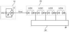
도 1에 도시된 바와 같이 본 발명에 따른 방열특성이 개선된 발광다이오드 조명장치는 전원공급부(10)와, 복수의 발광 다이오드 채널을 구비하는 광원부(20) 및 구동부(30)를 포함한다.As shown in FIG. 1 , the light emitting diode lighting device with improved heat dissipation characteristics according to the present invention includes a
전원공급부(10)는 교류 전원이 변환된 정류전압(Vrec)을 출력하며, 교류전압을 공급하는 교류전원(VAC)과 교류전압을 정류하여 정류 전압을 출력하는 정류 회로(12)를 포함한다. 여기서 교류전원(VAC)은 상용 교류전원일 수 있다.The
정류회로(12)는 교류전원(VAC)의 정현파 파형을 갖는 교류전압을 전파 정류한 파형을 갖도록 정류전압을 출력한다. 따라서 정류전압은 상용 교류 전압의 반 주기 단위로 전압 레벨이 승하강하는 리플 성분을 갖는 특성이 있다.The
광원부(20)는 직렬로 연결된 복수 개의 발광다이오드 채널을 포함한다. 본 발명에서는 편의상 4개의 발광다이오드 채널을 구비하는 조명장치에 대해 설명하였으나 채널의 수는 조명장치의 용량 등에 따라 자유롭게 조정될 수 있다.The
각 발광 다이오드 채널(LED1, LED2, LED3, LED4)은 각각 하나 이상의 직렬 또는 병렬로 연결된 발광 다이오드를 포함할 수 있고, 본 발명에 따른 실시예는 각 발광 다이오드 채널(LED1, LED2, LED3, LED4)이 복수 개의 직렬 연결된 발광 다이오드를 포함하는 것을 예로 들어 설명한다. 도면에서 복수 개의 직렬 연결된 발광 다이오드는 첫째 단과 마지막 단의 것만 도시하고 중간의 연결 관계는 생략하고 파선으로 도시하였다.Each of the light-emitting diode channels (LED1, LED2, LED3, LED4) may include one or more light-emitting diodes connected in series or in parallel, respectively, in an embodiment according to the present invention, each light-emitting diode channel (LED1, LED2, LED3, LED4) An example including the plurality of series-connected light emitting diodes will be described. In the drawings, a plurality of series-connected light emitting diodes are illustrated with only the first and last stages, and the intermediate connection relationship is omitted and illustrated with dashed lines.
구동부(30)는 전원공급부(10)에서 공급되는 정류전압(Vrec)에 의해 광원부(20)의 각 발광 다이오드 채널(LED1, LED2, LED3, LED4)에 흐르는 전류를 센싱하여 각각의 턴온 전압에 대응하여 각 발광 다이오드 채널(LED1, LED2, LED3, LED4) 별로 순차적으로 발광 및 소광되도록 한다.
The
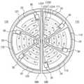
도 2는 본 발명의 일 실시예에 따른 방열특성이 개선된 발광다이오드 조명장치용 기판의 배치 구조를 설명하기 위한 도면이다.2 is a view for explaining the arrangement structure of a substrate for a light emitting diode lighting device with improved heat dissipation characteristics according to an embodiment of the present invention.
도 2를 참고하면 본 발명의 일 실시예에 따른 조명장치의 전원공급부(10)는 조명장치의 내부에 형성된 기판(100)의 중심부에 배치되고 그 주변에 광원부(20)가 배치되며, 기판(100)의 가장자리 부분에 구동부(30)가 배치된다.Referring to FIG. 2 , the
전원공급부(10)는 기판(100)의 중심부에 배치되어, 교류전압을 정류한 정류전압(Vrec)을 광원부(20) 및 구동부(30)에 공급한다.The
즉, 본 발명의 일 실시예의 경우 정류전압(Vrec)이 기판(100)의 중심부에서 공급되며 기판의 둘레 부분을 그라운드(GND)로 감싸는 구조를 갖는 것이 바람직하다.That is, in the case of an embodiment of the present invention, it is preferable to have a structure in which the rectified voltage Vrec is supplied from the center of the
그라운드를 기판의 둘레 부분에 설정하는 경우 발광다이오드 채널에 대한 패턴을 용이하게 구현할 수 있다. 또한 전원이 불안정한 지역에서는 누설전류가 많은데 기판의 둘레 부분을 그라운드로 감쌈으로써 외부 노이즈의 영향을 받지 않고 가장 안정적으로 동작할 수 있게 된다.When the ground is set on the periphery of the substrate, a pattern for the light emitting diode channel can be easily implemented. Also, there is a lot of leakage current in an area where the power is unstable. By wrapping the peripheral part of the board with the ground, it can operate most stably without being affected by external noise.
광원부(20)는 복수개의 발광다이오드를 구비하는 발광다이오드 채널로 구성된다.The
이때 흐르는 전류량이 가장 커서 발열량이 가장 많은 발광다이오드 채널(LED1)을 기판의 중심부에 배치하고, 기판의 가장자리로 갈수록 발열량이 상대적으로 작은 발광다이오드 채널을 배치하는 것이 바람직하다.At this time, it is preferable to arrange the light emitting diode channel LED1 with the largest amount of current flowing and the largest amount of heat generated at the center of the substrate, and the light emitting diode channel with a relatively smaller amount of heat generated toward the edge of the substrate.
이는 발열량이 가장 많은 발광다이오드 채널(LED1)을 기판의 중심부와 가까운 곳, 즉 구동부(30)로부터 먼 곳에 배치함으로써 구동부(30)의 집적회로 칩이 발광다이오드 채널(LED1)의 발열에 의해 받을 수 있는 영향을 최소화하기 위함이다.This is by arranging the light emitting diode channel LED1 with the largest amount of heat near the center of the substrate, that is, far from the
구동부(30)는 기판의 중심부로부터 먼 곳, 즉 기판의 가장자리 부분에 배치된다. 이와 같이 구동부(30)를 기판의 가장자리 부분에 배치하는 경우 기판의 중심부에 배치한 경우에 비해 구동부(30)에서 발생되는 열을 기판의 외부로 방출하는 것이 훨씬 용이해진다.The
집적회로 칩은 온도가 올라가면 그 동작의 신뢰성에 문제가 발생하게 되는데, 구동부(30)를 기판의 가장자리 부분에 배치하는 것과 함께 발열량이 가장 많은 발광다이오드 채널(LED1)로부터 가장 먼 곳에 배치하여 발광다이오드 채널(LED1)의 영향을 받지 않으면서 구동부(30)에서 발생하는 열을 효과적으로 외부로 방출하도록 함으로써 구동부(30) 내에 구비된 집적회로 칩의 온도를 일정하게 유지할 수 있게 된다.When the temperature of the integrated circuit chip rises, a problem occurs in the reliability of its operation. The
한편, 기판에 구동부(30)와 광원부(20)만을 배치하고 전원공급부(10)를 빼서 다른 기판에 배치하는 것도 가능하다.On the other hand, it is also possible to arrange only the
하나의 기판에 실장되는 광원부 및 구동부는 하나의 기판 위에 단위영역(101~105)의 형태로 복수개가 배치될 수 있다.A plurality of light source units and driving units mounted on one substrate may be disposed in the form of
대용량 조명장치에 있어서 하나의 기판에 하나의 광원부 및 하나의 구동부를 구비하는 경우 광원부 및 구동부의 일부에 장애가 발생하게 되면 조명장치 전체가 기능을 하지 못할 수도 있으며, 조명장치의 휘도 및 밝기를 조절하는데 어려움이 발생할 수 있다.In a large-capacity lighting device, if one light source unit and one driving unit are provided on one substrate, if a part of the light source unit and the driving unit fails, the entire lighting device may not function, and the brightness and brightness of the lighting device are adjusted. difficulties may arise.
이때 기판을 소정의 단위영역(101~105)으로 분할한 후 분할된 각 단위영역에 광원부와 구동부를 각각 배치하여 독립적으로 동작하도록 함으로써 일부 단위영역(101)에서 문제가 발생하더라도 다른 단위영역(102~105)에 실장된 광원부의 발광다이오드를 턴온시켜 조명장치의 기능을 수행할 수 있게 된다.At this time, after dividing the substrate into predetermined
도 2에서 단위영역(102~105)의 세부구성은 단위영역(101)과 동일하므로 발광다이오드 채널(LED1~LED4)의 표시는 생략하였다.In FIG. 2 , since the detailed configuration of the
도 3은 본 발명의 다른 일 실시예에 따른 방열특성이 개선된 발광다이오드 조명장치용 기판의 배치 구조를 설명하기 위한 도면이다.3 is a view for explaining the arrangement structure of a substrate for a light emitting diode lighting device with improved heat dissipation characteristics according to another embodiment of the present invention.
도 3을 참고하면 본 발명의 일 실시예에 따른 조명장치의 전원공급부(10)는 조명장치의 내부에 형성된 기판(100)의 중심부에 배치되고 그 주변에 구동부(30)가 배치되며, 기판(100)의 가장자리 부분에 광원부(20)가 배치된다.Referring to FIG. 3 , the
도 3에 도시된 발광다이오드 조명장치는 도 2에 도시된 발광다이오드 조명장치와 비교하여 구동부(30)가 기판의 중심부에 가깝게 배치되고 광원부(20)가 기판(100)의 가장자리 부분에 배치된 점에서 차이가 있다.Compared to the light emitting diode lighting device shown in FIG. 2 , in the light emitting diode lighting device shown in FIG. 3 , the
일반적인 발광다이오드 조명장치의 경우 광원부 보다 구동부에서 더 많은 열이 발생되므로 도 2에서와 같이 광원부와 구동부를 이격시켜 배치하되, 구동부를 기판의 가장자리 부분에 배치하게 된다.In the case of a general light emitting diode lighting device, since more heat is generated in the driving unit than in the light source unit, the light source unit and the driving unit are spaced apart as shown in FIG. 2, but the driving unit is arranged at the edge of the substrate.
그러나, 구동부보다 광원부에서 더 많은 열이 발생하는 일부 조명장치의 경우에는, 도 3에 도시된 바와 같이 구동부를 기판의 중심부에 가깝게 배치하고 발열량이 많은 광원부를 기판의 가장자리 부분에 배치하는 것이 기판의 열을 방출시키는데 더 효과적이다.However, in the case of some lighting devices that generate more heat from the light source than the driver, as shown in FIG. 3 , disposing the driving unit close to the center of the substrate and arranging the light source unit with a large amount of heat at the edge of the substrate It is more effective at dissipating heat.
이때 흐르는 전류량이 가장 커서 발열량이 가장 많은 발광다이오드 채널(LED1)을 기판의 가장자리 부분에 배치하고, 기판의 중심부에 가까울수록 발열량이 상대적으로 작은 발광다이오드 채널을 배치하는 것이 바람직하다.At this time, it is preferable to arrange the light emitting diode channel LED1 having the largest amount of current flowing and generating the largest amount of heat at the edge of the substrate, and the light emitting diode channel having a relatively smaller amount of heat as it approaches the center of the substrate.
즉, 발열량이 가장 많은 발광다이오드 채널(LED1)을 기판의 가장자리부에 배치함으로써 광원부에서 발생한 열을 기판의 외부로 용이하게 방출할 수 있게 된다. 또한, 발열량이 가장 많은 발광다이오드 채널(LED1)을 구동부(30)로부터 먼 곳에 배치함으로써 구동부(30)의 집적회로 칩이 발광다이오드 채널(LED1)의 발열에 의해 받을 수 있는 영향을 최소화 할 수 있다.
That is, by disposing the light emitting diode channel LED1 having the largest amount of heat at the edge of the substrate, heat generated from the light source can be easily radiated to the outside of the substrate. In addition, by disposing the light emitting diode channel LED1 with the largest amount of heat away from the driving
도 4는 본 발명의 다른 일 실시예에 따른 방열특성이 개선된 발광다이오드 조명장치의 기판의 배치를 설명하기 위한 도면이다.4 is a view for explaining the arrangement of a substrate of a light emitting diode lighting device with improved heat dissipation characteristics according to another embodiment of the present invention.
도 2 및 도 3에 도시된 실시예의 경우 전원공급부와 광원부 및 구동부가 하나의 기판에 배치되어 동작하는 것임에 반해 도 4에 도시된 실시예의 경우 전원공급부와 광원부 및 구동부가 두 개의 기판(110, 120)에 각각 별개로 배치되어 독립적으로 동작하는 것을 나타내고 있다.In the embodiment shown in FIGS. 2 and 3, the power supply unit, the light source unit, and the driving unit are arranged and operated on one substrate, whereas in the embodiment shown in FIG. 4, the power supply unit, the light source unit, and the driving unit are two
도 4에서와 같이 전원공급부(10)와 광원부(20) 및 구동부(30)가 두 개의 기판(110, 120)에 각각 별개로 배치된 경우 하나의 기판(110)에 문제가 발생되더라도 다른 기판(120)이 독립적으로 작동하여 그 기판(120)에 실장된 발광다이오드 채널을 턴온 시킴으로서 조명장치의 기능을 수행할 수 있게 된다.As shown in FIG. 4, when the
한편, 복수개의 기판(110, 120)은 각각 소정의 단위영역(111~113, 121~123)으로 분할될 수 있고 광원부(20) 및 구동부(30)가 각각의 단위영역에 배치될 수 있다.Meanwhile, the plurality of
상기 복수개의 기판은 서로 1mm 이상 이격시킴으로써 복수개의 기판 상호간에 미치는 영향을 최소화시키는 것이 바람직하다.It is preferable that the plurality of substrates be spaced apart from each other by 1 mm or more to minimize the influence between the plurality of substrates.
또한 기판(110)의 분할된 단위영역(111~113)에 배치된 광원부(20) 및 구동부(30)와 기판(120)의 분할된 단위영역(121~123)에 배치된 광원부(20) 및 구동부(30)는 서로 대칭 구조로 배치될 수 있다.In addition, the
도 4에서는 두 개의 기판을 예로 들어 설명하였으나 전원공급부와 광원부 및 구동부가 세 개 이상의 기판에 배치되어 동작할 수 있음은 당연하다.Although two substrates have been described as an example in FIG. 4 , it is natural that the power supply unit, the light source unit, and the driving unit may be disposed on three or more substrates to operate.
한편, 도 4에서는 광원부(20)가 기판의 중심부에 가깝게 배치되고 구동부(30)가 기판의 가장자리 부분에 배치된 것을 예로 들어 설명하였으나 구동부(30)가 기판의 중심부에 가깝게 배치되고 광원부(20)가 기판의 가장자리 부분에 배치되어 동작할 수 있음은 당연하다.Meanwhile, in FIG. 4 , the
본 발명에 따른 조명장치의 경우 AC 다이렉트 조명장치를 예로 들어 설명하였으나 AC 다이렉트 조명 장치뿐 만 아니라 일반적인 발광다이오드 조명장치에도 다양하게 적용할 수 있다.In the case of the lighting device according to the present invention, an AC direct lighting device has been described as an example, but it can be variously applied not only to the AC direct lighting device but also to a general light emitting diode lighting device.
상술한 바와 같이 구성 및 동작되는 본 발명의 실시예는 발광다이오드 채널을 구동하는 구동부와 광원부를 서로 이격시켜 배치하여 구동부 및 광원부에서 발생하는 열을 효과적으로 방출하도록 함으로써 발광다이오드 채널 및 구동부의 손상을 방지하고 수명을 증대시킬 수 있으며, 이를 통해 발광다이오드 조명장치의 전체적인 성능을 향상시킬 수 있는 효과가 있다.The embodiment of the present invention constructed and operated as described above prevents damage to the light emitting diode channel and the driving unit by arranging the driving unit and the light source unit to be spaced apart from each other to effectively dissipate heat generated from the driving unit and the light source unit. And it is possible to increase the lifespan, thereby having the effect of improving the overall performance of the light emitting diode lighting device.
또한 본 발명의 실시예는 구동부와 광원부를 서로 이격시켜 배치하는 것과 함께 복수개의 발광다이오드 채널 중 발열량이 가장 많은 채널을 구동부에서 가장 먼 곳에 배치함으로써 발광다이오드 채널에서 발생하는 열에 의해 구동부가 영향을 받는 것을 최소화할 수 있다.
In addition, in the embodiment of the present invention, the driving unit is affected by heat generated from the light emitting diode channel by disposing the driving unit and the light source unit spaced apart from each other and arranging the channel with the greatest amount of heat among the plurality of light emitting diode channels farthest from the driving unit. can be minimized
10 : 전원 공급부20 : 광원부
30 : 구동부 100 : 기판10: power supply unit 20: light source unit
30: driving unit 100: substrate
Claims (11)
Translated fromKorean하나 이상의 발광다이오드를 포함하는 복수 개의 발광다이오드 채널을 구비하는 광원부; 및
정류전압을 인가받아 상기 광원부를 구동하기 위한 구동부;를 포함하되,
상기 광원부와 상기 구동부는 상기 발광다이오드 조명장치의 내부에 구비된 기판에 이격하여 배치되며,
상기 복수개의 발광다이오드 채널 중 발열량이 가장 많은 발광다이오드 채널이 상기 구동부로부터 가장 먼 곳에 배치되고,
상기 기판의 둘레 부분을 그라운드로 감싸서 그라운드 전압을 형성한 것을 특징으로 하는 방열특성이 개선된 발광다이오드 조명장치.
In the light emitting diode lighting device,
a light source unit having a plurality of light emitting diode channels including one or more light emitting diodes; and
A driving unit for driving the light source unit by receiving a rectified voltage;
The light source unit and the driving unit are disposed to be spaced apart from the substrate provided inside the light emitting diode lighting device,
Among the plurality of light emitting diode channels, the light emitting diode channel having the largest amount of heat is disposed at the farthest from the driving unit,
A light emitting diode lighting device with improved heat dissipation characteristics, characterized in that a ground voltage is formed by surrounding a peripheral portion of the substrate with a ground.
상기 구동부는 상기 기판의 중심부에 배치되고,
상기 복수개의 발광다이오드 채널 중 발열량이 가장 많은 발광다이오드 채널은 상기 구동부로부터 가장 먼 곳에 배치되는 것을 특징으로 하는 방열특성이 개선된 발광다이오드 조명장치.
The method of claim 1
The driving unit is disposed in the center of the substrate,
A light emitting diode lighting device with improved heat dissipation characteristics, characterized in that the light emitting diode channel having the largest amount of heat among the plurality of light emitting diode channels is disposed at the farthest from the driving unit.
상기 복수개의 발광다이오드 채널 중 발열량이 가장 많은 발광다이오드 채널이 상기 기판의 중심부에 배치되고,
상기 구동부는 상기 복수개의 발광다이오드 채널 중 발열량이 가장 많은 발광다이오드 채널로부터 가장 먼 곳에 배치된 것을 특징으로 하는 방열특성이 개선된 발광다이오드 조명장치.
The method of claim 1
Among the plurality of light emitting diode channels, a light emitting diode channel having the largest amount of heat is disposed in the center of the substrate,
The driving unit is a light emitting diode lighting device with improved heat dissipation characteristics, characterized in that it is disposed farthest from the light emitting diode channel having the largest amount of heat among the plurality of light emitting diode channels.
상기 복수개의 발광다이오드 채널 중 발열량이 가장 많은 발광다이오드 채널을 상기 구동부로부터 가장 먼 곳에 배치하고 발열량이 가장 적은 발광다이오드 채널을 상기 구동부 근처에 배치하는 것을 특징으로 하는 방열특성이 개선된 발광다이오드 조명장치.
The method of claim 2 or 3, wherein the light source unit
Light emitting diode lighting device with improved heat dissipation characteristics, characterized in that among the plurality of light emitting diode channels, a light emitting diode channel with the largest amount of heat is disposed farthest from the driving unit and a light emitting diode channel with the least amount of heat is disposed near the driving unit. .
상기 복수개의 발광다이오드 채널 중 상기 구동부로부터 가장 먼 곳에 배치된 발광다이오드 채널에 구비된 발광다이오드로부터 상기 구동부 근처에 배치된 발광다이오드 채널에 구비된 발광다이오드까지 순차적으로 발광되는 것을 특징으로 하는 방열특성이 개선된 발광다이오드 조명장치.
The method of claim 5, wherein the light source unit
Heat dissipation characteristics, characterized in that light is sequentially emitted from the light emitting diode provided in the light emitting diode channel disposed farthest from the driving unit among the plurality of light emitting diode channels to the light emitting diode provided in the light emitting diode channel disposed near the driving unit. An improved light-emitting diode lighting device.
상기 기판은 복수 개의 단위영역으로 분할 가능하고,
상기 복수 개의 단위영역에는 상기 광원부 및 상기 구동부가 별도로 배치되며, 상기 복수개의 단위영역은 독립적으로 동작하는 것을 특징으로 하는 방열특성이 개선된 발광다이오드 조명장치.
4. The method of claim 2 or 3,
The substrate can be divided into a plurality of unit areas,
The light source unit and the driving unit are separately disposed in the plurality of unit areas, and the plurality of unit areas operate independently.
교류전원을 이용하여 상기 정류전압을 제공하는 전원공급부를 더 구비하는 것을 특징으로 하는 방열특성이 개선된 발광다이오드 조명장치.
According to claim 1,
Light-emitting diode lighting device with improved heat dissipation characteristics, characterized in that it further comprises a power supply for providing the rectified voltage using AC power.
상기 기판은 복수 개로 이루어지며, 상기 복수 개의 기판은,
상기 광원부 및 상기 구동부를 각각 구비하되,
상기 복수개의 발광다이오드 채널 중 발열량이 가장 많은 발광다이오드 채널이 상기 구동부로부터 가장 먼 곳에 각각 배치되는 것을 특징으로 하는 방열특성이 개선된 발광다이오드 조명장치.
According to claim 1,
The substrate consists of a plurality, the plurality of substrates,
Provided with each of the light source unit and the driving unit,
A light emitting diode lighting device with improved heat dissipation characteristics, wherein a light emitting diode channel having the largest amount of heat among the plurality of light emitting diode channels is disposed at the farthest from the driving unit.
상기 복수개의 기판은 두 개의 기판으로 이루어지며
상기 두 개의 기판에 각각 분할된 상기 복수개의 단위영역은 서로 대칭적으로 배치된 것을 특징으로 하는 방열특성이 개선된 발광다이오드 조명장치.
10. The method of claim 9,
The plurality of substrates consists of two substrates,
The light emitting diode lighting device with improved heat dissipation characteristics, characterized in that the plurality of unit regions divided on the two substrates are symmetrically disposed with each other.
상기 복수개의 기판은 서로 1mm 이상 이격되어 있는 것을 특징으로 하는 방열특성이 개선된 발광다이오드 조명장치.11. The method of claim 10,
The plurality of substrates are light emitting diode lighting device with improved heat dissipation characteristics, characterized in that spaced apart from each other by 1 mm or more.
Priority Applications (4)
| Application Number | Priority Date | Filing Date | Title |
|---|---|---|---|
| KR1020140121777AKR102323418B1 (en) | 2014-09-15 | 2014-09-15 | Led lighting apparatus improved heat radiation property |
| US14/853,112US9587818B2 (en) | 2014-09-15 | 2015-09-14 | LED lighting apparatus with improved heat radiation property |
| DE102015011992.3ADE102015011992A1 (en) | 2014-09-15 | 2015-09-14 | LED lighting device with improved heat radiation property |
| CN201510586824.6ACN105423139A (en) | 2014-09-15 | 2015-09-15 | LED lighting apparatus with improved heat radiation property |
Applications Claiming Priority (1)
| Application Number | Priority Date | Filing Date | Title |
|---|---|---|---|
| KR1020140121777AKR102323418B1 (en) | 2014-09-15 | 2014-09-15 | Led lighting apparatus improved heat radiation property |
Publications (2)
| Publication Number | Publication Date |
|---|---|
| KR20160032304A KR20160032304A (en) | 2016-03-24 |
| KR102323418B1true KR102323418B1 (en) | 2021-11-08 |
Family
ID=55406144
Family Applications (1)
| Application Number | Title | Priority Date | Filing Date |
|---|---|---|---|
| KR1020140121777AActiveKR102323418B1 (en) | 2014-09-15 | 2014-09-15 | Led lighting apparatus improved heat radiation property |
Country Status (4)
| Country | Link |
|---|---|
| US (1) | US9587818B2 (en) |
| KR (1) | KR102323418B1 (en) |
| CN (1) | CN105423139A (en) |
| DE (1) | DE102015011992A1 (en) |
Families Citing this family (2)
| Publication number | Priority date | Publication date | Assignee | Title |
|---|---|---|---|---|
| DE102016114694A1 (en)* | 2016-08-09 | 2018-02-15 | Arnold & Richter Cine Technik Gmbh & Co. Betriebs Kg | Headlight and light source arrangement for a headlight |
| CN106439640A (en)* | 2016-08-29 | 2017-02-22 | 苏州市昆士莱照明科技有限公司 | Infrared induction LED mining lamp |
Citations (2)
| Publication number | Priority date | Publication date | Assignee | Title |
|---|---|---|---|---|
| JP2009054490A (en)* | 2007-08-28 | 2009-03-12 | Panasonic Electric Works Co Ltd | Discharge lamp lighting device and lighting apparatus using the same |
| KR101308698B1 (en)* | 2013-03-12 | 2013-09-13 | 주식회사 이디엠아이 | Thermally superior led circuit board |
Family Cites Families (15)
| Publication number | Priority date | Publication date | Assignee | Title |
|---|---|---|---|---|
| JPS556687A (en)* | 1978-06-29 | 1980-01-18 | Handotai Kenkyu Shinkokai | Traffic use display |
| GB2383180B (en)* | 2001-12-11 | 2005-05-04 | Westinghouse Brake & Signal | Signal lamps and apparatus |
| KR101017643B1 (en)* | 2008-10-31 | 2011-02-28 | 주식회사 코아룩스 | Removable LED lighting module |
| KR101048257B1 (en) | 2009-08-19 | 2011-07-08 | 엘지이노텍 주식회사 | LED driving circuit |
| KR20110125083A (en) | 2010-05-12 | 2011-11-18 | (주)다비치 | LED heating control system and lighting control method for landscape lighting |
| JP2012015148A (en)* | 2010-06-29 | 2012-01-19 | Rohm Co Ltd | Led module and led lighting system |
| TWI445158B (en)* | 2011-03-14 | 2014-07-11 | Interlight Optotech Corp | Illuminating device |
| JP2013251144A (en)* | 2012-05-31 | 2013-12-12 | Toshiba Lighting & Technology Corp | Light-emitting module and luminaire |
| JP2014036107A (en)* | 2012-08-08 | 2014-02-24 | Toshiba Lighting & Technology Corp | Light-emitting module and luminaire |
| US20140097753A1 (en)* | 2012-10-05 | 2014-04-10 | David Hui | LED Lighting system for self-dissipation of heat |
| JP6029100B2 (en) | 2012-10-25 | 2016-11-24 | シチズン時計株式会社 | Light emitting device |
| CN203099579U (en)* | 2012-11-19 | 2013-07-31 | 欧普照明股份有限公司 | Lighting lamp |
| CN104938029B (en)* | 2012-12-28 | 2018-04-17 | 硅工厂股份有限公司 | The control circuit of light emitting diode illuminating apparatus |
| CN203131716U (en)* | 2013-01-06 | 2013-08-14 | 广州奥迪通用照明有限公司 | Integrated light source board for bulb light |
| JP2014157795A (en) | 2013-02-18 | 2014-08-28 | Panasonic Corp | Light source for lighting and lighting device |
- 2014
- 2014-09-15KRKR1020140121777Apatent/KR102323418B1/enactiveActive
- 2015
- 2015-09-14USUS14/853,112patent/US9587818B2/enactiveActive
- 2015-09-14DEDE102015011992.3Apatent/DE102015011992A1/ennot_activeWithdrawn
- 2015-09-15CNCN201510586824.6Apatent/CN105423139A/enactivePending
Patent Citations (2)
| Publication number | Priority date | Publication date | Assignee | Title |
|---|---|---|---|---|
| JP2009054490A (en)* | 2007-08-28 | 2009-03-12 | Panasonic Electric Works Co Ltd | Discharge lamp lighting device and lighting apparatus using the same |
| KR101308698B1 (en)* | 2013-03-12 | 2013-09-13 | 주식회사 이디엠아이 | Thermally superior led circuit board |
Also Published As
| Publication number | Publication date |
|---|---|
| DE102015011992A1 (en) | 2016-03-17 |
| CN105423139A (en) | 2016-03-23 |
| US20160076753A1 (en) | 2016-03-17 |
| KR20160032304A (en) | 2016-03-24 |
| US9587818B2 (en) | 2017-03-07 |
Similar Documents
| Publication | Publication Date | Title |
|---|---|---|
| US9041303B2 (en) | AC LED lighting apparatus | |
| TWI458144B (en) | Distributed led-based light source | |
| JP3965419B1 (en) | Lighting device | |
| JP5331095B2 (en) | AC light-emitting diode lamp | |
| US20180259166A1 (en) | Light source module and lighting device having same | |
| US20120020089A1 (en) | Light emitting diode light bar | |
| JP3972056B1 (en) | Lighting device | |
| CN102213371B (en) | Lamp structure | |
| US8471481B2 (en) | Lighting apparatus using PN junction light-emitting element and dimming method thereof | |
| KR102323418B1 (en) | Led lighting apparatus improved heat radiation property | |
| KR101276326B1 (en) | Pcb with via hole, led module and led light | |
| JP2008135359A (en) | Lighting apparatus | |
| US20120025719A1 (en) | LED Tube and Drive Circuit thereof | |
| KR101217689B1 (en) | Led lamp | |
| KR101338899B1 (en) | LED lighting device | |
| KR101407687B1 (en) | Large LED lamp with excellent heat dissipation effect | |
| TW201916749A (en) | Light-emitting diode driving circuit and lighting apparatus thereof | |
| TW201430271A (en) | LED device | |
| JP2015050150A (en) | Lighting fixture, led bulb, lighting device, and light-emitting module | |
| RU2465688C1 (en) | Light diode lamp | |
| KR20120111304A (en) | Led illumination equipment | |
| KR20160064575A (en) | Light emitting diode lighting apparatus | |
| CN207560382U (en) | A kind of Novel LED bulkhead lamp module | |
| US20140184070A1 (en) | Luminarie | |
| JP6406516B2 (en) | Lighting device |
Legal Events
| Date | Code | Title | Description |
|---|---|---|---|
| PA0109 | Patent application | St.27 status event code:A-0-1-A10-A12-nap-PA0109 | |
| PG1501 | Laying open of application | St.27 status event code:A-1-1-Q10-Q12-nap-PG1501 | |
| PN2301 | Change of applicant | St.27 status event code:A-3-3-R10-R13-asn-PN2301 St.27 status event code:A-3-3-R10-R11-asn-PN2301 | |
| PA0201 | Request for examination | St.27 status event code:A-1-2-D10-D11-exm-PA0201 | |
| D13-X000 | Search requested | St.27 status event code:A-1-2-D10-D13-srh-X000 | |
| D14-X000 | Search report completed | St.27 status event code:A-1-2-D10-D14-srh-X000 | |
| E902 | Notification of reason for refusal | ||
| PE0902 | Notice of grounds for rejection | St.27 status event code:A-1-2-D10-D21-exm-PE0902 | |
| E13-X000 | Pre-grant limitation requested | St.27 status event code:A-2-3-E10-E13-lim-X000 | |
| P11-X000 | Amendment of application requested | St.27 status event code:A-2-2-P10-P11-nap-X000 | |
| P13-X000 | Application amended | St.27 status event code:A-2-2-P10-P13-nap-X000 | |
| R18-X000 | Changes to party contact information recorded | St.27 status event code:A-3-3-R10-R18-oth-X000 | |
| E701 | Decision to grant or registration of patent right | ||
| PE0701 | Decision of registration | St.27 status event code:A-1-2-D10-D22-exm-PE0701 | |
| PN2301 | Change of applicant | St.27 status event code:A-3-3-R10-R13-asn-PN2301 St.27 status event code:A-3-3-R10-R11-asn-PN2301 | |
| PN2301 | Change of applicant | St.27 status event code:A-3-3-R10-R13-asn-PN2301 St.27 status event code:A-3-3-R10-R11-asn-PN2301 | |
| GRNT | Written decision to grant | ||
| PR0701 | Registration of establishment | St.27 status event code:A-2-4-F10-F11-exm-PR0701 | |
| PR1002 | Payment of registration fee | St.27 status event code:A-2-2-U10-U11-oth-PR1002 Fee payment year number:1 | |
| PG1601 | Publication of registration | St.27 status event code:A-4-4-Q10-Q13-nap-PG1601 | |
| R17-X000 | Change to representative recorded | St.27 status event code:A-5-5-R10-R17-oth-X000 | |
| PR1001 | Payment of annual fee | St.27 status event code:A-4-4-U10-U11-oth-PR1001 Fee payment year number:4 | |
| PR1001 | Payment of annual fee | St.27 status event code:A-4-4-U10-U11-oth-PR1001 Fee payment year number:5 |