KR102321918B1 - Shear wave detection in medical ultrasound imaging - Google Patents
Shear wave detection in medical ultrasound imagingDownload PDFInfo
- Publication number
- KR102321918B1 KR102321918B1KR1020140131904AKR20140131904AKR102321918B1KR 102321918 B1KR102321918 B1KR 102321918B1KR 1020140131904 AKR1020140131904 AKR 1020140131904AKR 20140131904 AKR20140131904 AKR 20140131904AKR 102321918 B1KR102321918 B1KR 102321918B1
- Authority
- KR
- South Korea
- Prior art keywords
- shear wave
- ultrasound
- time
- shear
- displacements
- Prior art date
- Legal status (The legal status is an assumption and is not a legal conclusion. Google has not performed a legal analysis and makes no representation as to the accuracy of the status listed.)
- Active
Links
Images


Classifications
- A—HUMAN NECESSITIES
- A61—MEDICAL OR VETERINARY SCIENCE; HYGIENE
- A61B—DIAGNOSIS; SURGERY; IDENTIFICATION
- A61B8/00—Diagnosis using ultrasonic, sonic or infrasonic waves
- A61B8/08—Clinical applications
- A61B8/0833—Clinical applications involving detecting or locating foreign bodies or organic structures
- A61B8/085—Clinical applications involving detecting or locating foreign bodies or organic structures for locating body or organic structures, e.g. tumours, calculi, blood vessels, nodules
- A—HUMAN NECESSITIES
- A61—MEDICAL OR VETERINARY SCIENCE; HYGIENE
- A61B—DIAGNOSIS; SURGERY; IDENTIFICATION
- A61B8/00—Diagnosis using ultrasonic, sonic or infrasonic waves
- A61B8/48—Diagnostic techniques
- A61B8/485—Diagnostic techniques involving measuring strain or elastic properties
- A—HUMAN NECESSITIES
- A61—MEDICAL OR VETERINARY SCIENCE; HYGIENE
- A61B—DIAGNOSIS; SURGERY; IDENTIFICATION
- A61B8/00—Diagnosis using ultrasonic, sonic or infrasonic waves
- A61B8/52—Devices using data or image processing specially adapted for diagnosis using ultrasonic, sonic or infrasonic waves
- A61B8/5269—Devices using data or image processing specially adapted for diagnosis using ultrasonic, sonic or infrasonic waves involving detection or reduction of artifacts
- A—HUMAN NECESSITIES
- A61—MEDICAL OR VETERINARY SCIENCE; HYGIENE
- A61B—DIAGNOSIS; SURGERY; IDENTIFICATION
- A61B8/00—Diagnosis using ultrasonic, sonic or infrasonic waves
- A61B8/58—Testing, adjusting or calibrating the diagnostic device
- A61B8/587—Calibration phantoms
- G—PHYSICS
- G01—MEASURING; TESTING
- G01S—RADIO DIRECTION-FINDING; RADIO NAVIGATION; DETERMINING DISTANCE OR VELOCITY BY USE OF RADIO WAVES; LOCATING OR PRESENCE-DETECTING BY USE OF THE REFLECTION OR RERADIATION OF RADIO WAVES; ANALOGOUS ARRANGEMENTS USING OTHER WAVES
- G01S7/00—Details of systems according to groups G01S13/00, G01S15/00, G01S17/00
- G01S7/52—Details of systems according to groups G01S13/00, G01S15/00, G01S17/00 of systems according to group G01S15/00
- G01S7/52017—Details of systems according to groups G01S13/00, G01S15/00, G01S17/00 of systems according to group G01S15/00 particularly adapted to short-range imaging
- G01S7/52023—Details of receivers
- G01S7/52036—Details of receivers using analysis of echo signal for target characterisation
- G01S7/52042—Details of receivers using analysis of echo signal for target characterisation determining elastic properties of the propagation medium or of the reflective target
- A—HUMAN NECESSITIES
- A61—MEDICAL OR VETERINARY SCIENCE; HYGIENE
- A61B—DIAGNOSIS; SURGERY; IDENTIFICATION
- A61B5/00—Measuring for diagnostic purposes; Identification of persons
- A61B5/72—Signal processing specially adapted for physiological signals or for diagnostic purposes
- A61B5/7203—Signal processing specially adapted for physiological signals or for diagnostic purposes for noise prevention, reduction or removal
- G—PHYSICS
- G01—MEASURING; TESTING
- G01S—RADIO DIRECTION-FINDING; RADIO NAVIGATION; DETERMINING DISTANCE OR VELOCITY BY USE OF RADIO WAVES; LOCATING OR PRESENCE-DETECTING BY USE OF THE REFLECTION OR RERADIATION OF RADIO WAVES; ANALOGOUS ARRANGEMENTS USING OTHER WAVES
- G01S7/00—Details of systems according to groups G01S13/00, G01S15/00, G01S17/00
- G01S7/52—Details of systems according to groups G01S13/00, G01S15/00, G01S17/00 of systems according to group G01S15/00
- G01S7/52017—Details of systems according to groups G01S13/00, G01S15/00, G01S17/00 of systems according to group G01S15/00 particularly adapted to short-range imaging
- G01S7/52019—Details of transmitters
- G01S7/5202—Details of transmitters for pulse systems
- G01S7/52022—Details of transmitters for pulse systems using a sequence of pulses, at least one pulse manipulating the transmissivity or reflexivity of the medium
Landscapes
- Health & Medical Sciences (AREA)
- Life Sciences & Earth Sciences (AREA)
- Engineering & Computer Science (AREA)
- Physics & Mathematics (AREA)
- General Health & Medical Sciences (AREA)
- Public Health (AREA)
- Veterinary Medicine (AREA)
- Pathology (AREA)
- Biomedical Technology (AREA)
- Heart & Thoracic Surgery (AREA)
- Medical Informatics (AREA)
- Molecular Biology (AREA)
- Surgery (AREA)
- Animal Behavior & Ethology (AREA)
- Biophysics (AREA)
- Radiology & Medical Imaging (AREA)
- Nuclear Medicine, Radiotherapy & Molecular Imaging (AREA)
- Computer Vision & Pattern Recognition (AREA)
- Vascular Medicine (AREA)
- General Physics & Mathematics (AREA)
- Remote Sensing (AREA)
- Radar, Positioning & Navigation (AREA)
- Computer Networks & Wireless Communication (AREA)
- Ultra Sonic Daignosis Equipment (AREA)
- Signal Processing (AREA)
- Artificial Intelligence (AREA)
- Physiology (AREA)
- Psychiatry (AREA)
Abstract
Translated fromKoreanDescription
Translated fromKorean본 실시예들은 전단파(shear wave) 초음파 영상에 관한 것이다. 조직을 통해 이동하는 전단파들이 검출될 수 있다. 전단 속도 또는 전단파의 다른 특성들은 조직의 경직도(stiffness of the tissue)와 같은 조직에 대한 진단(diagnostically)에 유용한 정보를 나타낼 수 있다. 물혹(Cysts), 죽은 조직 또는 다른 비정상적으로 경직되거나 부드러운 조직이 전단파 초음파 영상을 이용하여 검출될 수 있다.
The present embodiments relate to a shear wave ultrasound image. Shear waves traveling through the tissue can be detected. The shear rate or other properties of the shear wave may represent diagnostically useful information about the tissue, such as the stiffness of the tissue. Cysts, dead tissue, or other abnormally stiff or soft tissue can be detected using shear wave ultrasound imaging.
조직 내에서 전파하는 전단파들을 검출하는 것은, 탐촉자(transducer probe)에 대한 조직의 이동으로 인한 높은 수준의 노이즈(noise)를 겪을 수 있다. 초음파가 사용되기 때문에, 또한 음향 반향(acoustic reflection) 또는 잔향(reverberation)은 전단파의 검출시에 노이즈의 원인이 될 수 있다. 변위의 피크(peak) 검출, 상관 지연(correlation lag) 또는 다른 기술들을 이용한 전단파 검출은 노이즈로 인해 신뢰가 떨어질 수 있다.
Detecting shear waves propagating in tissue may suffer from a high level of noise due to movement of the tissue with respect to a transducer probe. Since ultrasound is used, also acoustic reflection or reverberation can be a source of noise in the detection of shear waves. Shear wave detection using displacement peak detection, correlation lag, or other techniques can be unreliable due to noise.
도입부로서, 이하에 설명되는 바람직한 실시예들은 초음파에 의한 전단파 검출을 위한 방법들, 명령들 및 시스템(system)들을 포함한다. 전단파의 검출은 보다 제어된 환경(예컨대, 노이즈가 적은 환경)에서 이전 측정들을 사용하는 것으로 제한되고 있다. 예컨대, 인체모형(phantom)에서 측정된 전단파들은 잘못된 피크(peak) 검출들을 회피하기 위해서 환자 내의 전단파들의 검출을 제한하는데 사용된다.
As an introduction, preferred embodiments described below include methods, instructions and systems for shear wave detection by ultrasound. Detection of shear waves is limited to using previous measurements in a more controlled environment (eg, less noisy environment). For example, shear waves measured in a phantom are used to limit the detection of shear waves in the patient to avoid false peak detections.
제 1 양태에서, 초음파에 의한 전단파 검출을 위한 방법이 제공된다. 변환기(transducer)가 음향 방사력 가진(acoustic radiation force excitation)을 환자에게 전송한다. 음향 방사력 가진으로부터 초래되는 전단파에 응답하여 환자 내의 조직의 위치에서의 변위들을 측정하기 위해서 초음파가 사용된다. 프로세서(processor)가 변위들의 최대 변위를 판정한다. 최대 변위에 기초하여 메모리(memory)로부터 미리 규정된 제한(constraint)으로서 시간 범위가 식별된다. 프로세서는 시간 범위 내에서 변위들로부터 하나의 시간을 정하여 시간에 따른 전단파 속도를 산출한다. 전단파 속도의 표시가 디스플레이된다(displayed).
In a first aspect, a method for shear wave detection by ultrasound is provided. A transducer transmits an acoustic radiation force excitation to the patient. Ultrasound is used to measure displacements in the location of tissue within a patient in response to a shear wave resulting from an acoustic radiation force excitation. A processor determines the maximum displacement of the displacements. A time span is identified as a predefined constraint from memory based on the maximum displacement. The processor computes the shear wave velocity over time by taking one time from the displacements within the time range. An indication of the shear wave velocity is displayed.
제 2 양태에서, 비일시적인(non-transitory) 컴퓨터(computer) 판독 가능한 저장 매체는 초음파에 의한 전단파 검출을 위해 프로그램된 프로세서(programmed processor)에 의해 실행 가능한 명령들을 나타내는 데이터(data)를 그 안에 저장한다. 저장 매체는 환자 내의 위치에 대한 시간에 걸친 변위들, 전단파에 응답하는 변위들의 제 1 특질을 판정하고, 제 1 특질에 따라 이전의 제 2 특질을 검색하며, 이전의 제 2 특질에 의해 변위들을 위한 서치(search) 범위를 제한하고, 그리고 서치 범위를 사용하여 전단파를 검출하는 명령들을 포함한다.
In a second aspect, a non-transitory computer readable storage medium stores therein data representing instructions executable by a programmed processor for shear wave detection by ultrasound. do. The storage medium determines displacements over time relative to a location in the patient, a first characteristic of displacements responsive to a shear wave, retrieves a previous second characteristic according to the first characteristic, and retrieves the displacements by the previous second characteristic. It includes instructions for limiting a search range for , and detecting a shear wave using the search range.
제 3 양태에서, 초음파에 의한 전단파 검출을 위한 시스템이 제공된다. 변환기가 환자 내로의 음향 임펄스 가진(acoustic impulse excitation)을 전송하도록 구성되며, 환자의 구역을 초음파로 스캔(scan)하도록 구성된다. 수신 빔형성기(receive beamformer)는 음향 임펄스 가진 이후 상이한 시간들에서 구역을 나타내는 데이터를 발생시키도록 구성된다. 초음파에 의한 스캔(scan)으로부터 데이터가 발생된다. 프로세서는, 이 데이터로부터 음향 임펄스 가진에 의해 유도되는 전단파에 의해 유발되는 조직 변위들을 추정하고, 조직 변위들로부터 전단파의 특성을 추정하며, 특성을 추정하기 위해 추정된 조직 변위들의 서치(search)를 제한하도록 구성된다. 서치는, 음향 임펄스 가진의 동일한 구성에 의해 획득되는 이전의 정보를 사용하여 제한된다.In a third aspect, a system for shear wave detection by ultrasound is provided. The transducer is configured to transmit an acoustic impulse excitation into the patient and is configured to scan an area of the patient with ultrasound. A receive beamformer is configured to generate data representative of the zone at different times after excitation of the acoustic impulse. Data is generated from a scan by ultrasound. The processor estimates from this data tissue displacements induced by the shear wave induced by the acoustic impulse excitation, estimates a property of the shear wave from the tissue displacements, and performs a search of the estimated tissue displacements to estimate the property. configured to limit. The search is limited using previous information obtained by the same configuration of acoustic impulse excitation.
본 발명은 하기 청구항들에 의해 규정되며, 이 부분의 어떠한 것도 이들 청구항들에 대한 제한으로서 여겨지지는 않는다. 본 발명의 추가 양태들 및 이점들은 바람직한 실시예들과 연관하여 하기에서 논의되며 추후 독립적으로 또는 조합하여 청구될 수 있다.
The invention is defined by the following claims, and nothing in this section is to be considered as a limitation on these claims. Additional aspects and advantages of the invention are discussed below in connection with preferred embodiments and may subsequently be claimed independently or in combination.
구성요소들 및 도면들은 반드시 실척일 필요는 없으며, 오히려 본 발명의 원리들을 예시할 때 강조된다. 또한, 도면들에서, 동일한 참조 부호들은 상이한 도면들에 걸쳐 대응하는 부분들을 나타낸다.
Elements and drawings are not necessarily to scale, rather emphasis is placed upon illustrating the principles of the invention. Also, in the drawings, like reference numerals indicate corresponding parts throughout different drawings.
도 1은 초음파에 의한 전단파 검출을 위한 방법의 일 실시예의 흐름도이다.
도 2는 시간에 따른 변위의 2 개의 예시적인 변위 프로파일(profile)들을 도시하는 그래프(graph)이다.
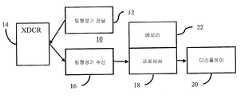
도 3은 초음파에 의한 전단파 검출을 위한 시스템의 일 실시예의 블록도(block diagram)이다.1 is a flowchart of one embodiment of a method for shear wave detection by ultrasound.
2 is a graph showing two exemplary displacement profiles of displacement over time.
3 is a block diagram of an embodiment of a system for shear wave detection by ultrasound.
전단파 검출은 서치 범위를 제한함으로써 개선될 수 있다. 제어된 환경에서 측정된 변위 파형의 특질들(예컨대, 변위 크기 및 이동 시간)의 세트(set)가 환자 내에서 검출을 제한하기 위해 사용된다. 제어된 환경의 일 예는 가진 전송 구성(excitation transmit configuration)을 유도하는 동일한 전단파에 의해 측정되는 인체모형(phantom)들이다. 조직의 기계적 특징 또는 특징들의 추정의 정확도 및 검출의 신뢰 수준 양자 모두는 심지어 낮은 신호 대 노이즈(low signal-to-noise) 변위 데이터에 의해 개선될 수 있다.
Shear wave detection can be improved by limiting the search range. A set of characteristics (eg, displacement magnitude and transit time) of the measured displacement waveform in a controlled environment is used to limit detection within the patient. One example of a controlled environment is phantoms measured by the same shear wave that induces an excitation transmit configuration. Both the accuracy of the estimation of the mechanical feature or features of the tissue and the confidence level of detection can be improved even by low signal-to-noise displacement data.
도 1은 초음파에 의한 전단파 검출을 위한 방법을 도시한다. 방법은 도 3의 시스템 또는 다른 시스템에 의해 실행된다. 부가적인, 다른 또는 더 적은 행동들이 제공될 수 있다. 예컨대, 행동(act)(42)이 대표적이며, 시간 검출 이외의 기술들이 전단파를 검출하기 위해서 사용될 수 있다. 다른 예로서, 행동(46)의 디스플레잉(displaying)이 선택적이다. 행동들은 설명된 또는 도시된 순서로 수행되지만, 다른 순서들로 수행될 수 있다.
1 shows a method for shear wave detection by ultrasound. The method is performed by the system of FIG. 3 or another system. Additional, different or fewer actions may be provided. For example,
행동(30)에서, 음향 가진이 환자 내부로 전송된다. 음향 가진은 변위를 야기하기 위한 임펄스 가진으로서 작용한다. 예컨대, 조직을 이미징(imaging)하기 위한 B-모드(mode) 전송들과 유사한 또는 이보다 더 낮은 동력 또는 피크 진폭 레벨(level)들을 갖는 400 사이클(cycle) 전송 파형이 음향 빔(beam)으로서 전송된다. 일 실시예에서, 전송은 시계(field of view)에 적용되는 전단파 발생 시퀀스(sequence)이다. 임의의 음향 방사력 임펄스(ARFI; acoustic radiation force impulse) 또는 전단파 이미징 시퀀스가 사용될 수 있다.
In
전송은 하나 또는 그 초과의 위치들에 조직을 변위시키기에 충분한 응력을 조직에 야기하는 동력, 진폭, 타이밍(timing) 또는 다른 특성에 의해 구성된다. 예컨대, 빔의 전송 포커스(focus)는 시계에 걸친 변위를 야기하기 위해 관심 영역(ROI; region of interest) 또는 시계의 바닥, 중심 근처에 위치된다. 전송은 상이한 하위 영역들 또는 ROI들을 위해 반복될 수 있다. 어퍼쳐(aperture), 주파수, 초점 위치, 진폭, F#, 또는 다른 특성을 포함하는 임의의 전송 구성이 사용될 수 있다.
Transmission is constituted by a force, amplitude, timing, or other characteristic that causes the tissue to stress sufficient to displace the tissue in one or more locations. For example, the transmission focus of the beam is positioned near the bottom, center of the field of view or region of interest (ROI) to cause displacement across the field of view. The transmission may be repeated for different sub-regions or ROIs. Any transmission configuration may be used, including aperture, frequency, focal position, amplitude, F#, or other characteristics.
가진은 초음파 변환기로부터 전송된다. 가진은 음향 에너지(energy)이다. 음향 에너지는 초점이 맞춰지고, 3-차원 빔 프로파일을 초래한다. 가진은 페이스형(phased) 어레이(array) 및/또는 기계적 포커스(focus)를 사용하여 초점이 맞춰진다. 가진은 높이 치수(elevation dimension)와 같은 하나의 치수에서 초점을 맞추지 않을 수 있다. 가진은 환자의 조직 안으로 전송된다.
Excitation is transmitted from an ultrasonic transducer. Excitation is acoustic energy. The acoustic energy is focused and results in a three-dimensional beam profile. Excitation is focused using a phased array and/or mechanical focus. Excitation may not focus on one dimension, such as the elevation dimension. Excitation is transmitted into the patient's tissue.
임펄스 가진은 공간적 위치에서 전단파를 발생한다. 가진이 충분히 강한 곳에서, 전단파가 발생된다. 전단파는 길이방향 파가 음파 방출 방향을 따라 전파하는 것보다 더 느리게 조직을 통하여 전파한다. 이러한 타이밍의 차이는, 특정한 시간들에서의 위치들을 샘플링하는(sampling) 바와 같이, 길이방향 파로부터 전단파를 격리시키는데 사용된다. 시간 범위 커버링(covering)과 같은 패싱(passing)(예컨대, 전단파의 출구를 통한 도착으로부터)이 변위들을 위해 샘플링된다(sampled).
Impulse excitation generates shear waves at spatial locations. Where the excitation is strong enough, a shear wave is generated. Shear waves propagate through tissue more slowly than longitudinal waves propagate along the direction of sound wave emission. This timing difference is used to isolate the shear wave from the longitudinal wave, such as sampling positions at specific times. A passing (eg, from arrival through the exit of a shear wave), such as a time range covering, is sampled for displacements.
전단파는 가해지는 응력의 방향에 수직한 방향을 포함하여 다양한 방향들로 전파된다. 전단파들의 변위는 전단파가 발생되는 위치에 더 가까운 위치들에서 더 크다. 전단파가 이동할 때, 전단파의 크기는 감쇠한다.
Shear waves propagate in a variety of directions, including those perpendicular to the direction of the applied stress. The displacement of the shear waves is greater at locations closer to the location where the shear waves are generated. As the shear wave travels, the magnitude of the shear wave is attenuated.
행동(32)에서, 환자 내의 전단파에 대한 변위 응답이 검출된다. 조직은 환자 내에서 이동하도록 강제된다. 예컨대, 2 개의 위치들에 대한 변위 프로파일들이 도 2에 도시된다. 가진은 조직의 변위를 야기한다. 전단파가 발생되고 초점 영역으로부터 전파한다. 전단파가 조직을 통하여 이동하기 때문에, 조직은 변위된다. 타이밍 및/또는 측방 위치는 발생된 다른 파들로부터 전단파를 구별하는데 사용된다. 길이방향 파들 또는 변위의 다른 원인들이 전단 대신 사용될 수 있다.
In
힘 또는 응력에 의해 야기되는 변위가 측정된다. 변위는 하나 또는 그 초과의 위치들에서 시간에 걸쳐 측정된다. 측정에 사용된 시간들은 길이방향 파보다 오히려 전단파를 캡쳐(capture)하도록 설정된다. 변위 측정은 응력 또는 임펄스가 끝나기 전에, 상이한 주파수 또는 코딩(coding)을 사용하는 것에 의해 시작될 수 있다. 대안적으로, 변위 측정은 임펄스가 끝난 후에 시작된다. 응력의 영역 또는 지점으로부터 이격된 조직의 변위를 야기하는 전단파, 길이방향 파 또는 다른 파가 이동하는데 시간이 걸리기 때문에, 이완된 또는 부분적으로 응력을 받은 상태로부터 최대 변위로의 그리고 그 후 이완된 상태로의 변위는 도 2 에 나타낸 것과 같이 측정될 수 있다. 변위의 시간적인 프로파일이 판정된다. 대안적으로, 변위는 단지 조직이 예상되는 최대 직전에, 최대에 또는 거의 근처에서부터 이완되는 동안에만 측정된다.
A displacement caused by a force or stress is measured. Displacement is measured over time at one or more locations. The times used for the measurements are set to capture a shear wave rather than a longitudinal wave. Displacement measurements can be started by using a different frequency or coding before the stress or impulse ends. Alternatively, the displacement measurement is started after the impulse is over. From a relaxed or partially stressed state to maximum displacement and thereafter a relaxed state because shear waves, longitudinal waves, or other waves that cause displacement of the tissue away from the region or point of stress take time to travel. The furnace displacement can be measured as shown in FIG. 2 . The temporal profile of the displacement is determined. Alternatively, displacement is measured only while the tissue is relaxing just before, at, or near the expected maximum.
측정값은 변위의 양 또는 크기이다. 조직은 임의의 방향으로 이동된다. 측정은 가장 큰 이동 방향을 따를 수 있다. 방향 벡터(motion vector)의 크기가 판정된다. 대안적으로, 측정은 조직이 다른 방향들로 다소 변위되는지 여부와 관계없이 스캔 라인(line)에 수직한 것과 같은 주어진 방향을 따른다.
A measure is the amount or magnitude of displacement. The tissue is moved in any direction. Measurements may follow the direction of greatest movement. The magnitude of the motion vector is determined. Alternatively, the measurement is along a given direction, such as perpendicular to the scan line, regardless of whether the tissue is displaced somewhat in other directions.
변위는 초음파 스캐닝(scanning)에 의해 검출된다. 초음파 데이터가 얻어진다. 초음파 데이터의 적어도 일부는 전단파에 대해 응답한다. 관심 영역, 전체 시계, 또는 하위 관심 영역과 같은 영역이 초음파에 의해 스캔된다(scanned). 영역은 전단파를 검출하기 위해 감시된다. 영역은 측방이 5 ㎜ 그리고 축방향이 10 ㎜ 인 것과 같은 임의의 크기이다. 예컨대, B-모드 스캔들은 전단파에 의해 야기되는 조직 변위를 검출하기 위해 수행된다. 도플러(Doppler), 색상 흐름(color flow) 또는 다른 초음파 모드가 전단파에 대해 감시하기 위해 사용될 수 있다.The displacement is detected by ultrasonic scanning. Ultrasound data is obtained. At least a portion of the ultrasound data is responsive to the shear wave. An area, such as a region of interest, a full field of view, or a sub-region of interest, is scanned by ultrasound. The area is monitored to detect shear waves. The area is of any size, such as 5 mm on the side and 10 mm on the axial direction. For example, B-mode scans are performed to detect tissue displacement caused by shear waves. Doppler, color flow or other ultrasound modes may be used to monitor for shear waves.
주어진 시간 동안, 초음파는 관심 영역 또는 조직에 전송된다. 임의의 현재 공지된 또는 추후 개발될 변위 이미징이 사용될 수 있다. 예컨대, 1 내지 5 사이클 지속 기간들을 갖는 펄스(pulse)들이 720 mW/㎠ 미만의 세기로 사용된다. 다른 세기들을 갖는 펄스들이 사용될 수 있다. 감시는 임의의 개수의 스캔 라인들에 대해 수행된다. 예컨대, 4 또는 8 개의 수용 빔들이 각각의 전송에 응답하여 형성된다. 전단파를 발생하기 위해 가진을 전송한 후에, B-모드 전송들이 단일 전송 스캔 라인 그리고 4 또는 8 개의 인접한 수신 스캔 라인들을 따른 수신부(reception)들을 따라 반복적으로 수행된다. 다른 실시예들에서, 단지 단일 수신 빔 또는 다른 개수의 수신 빔들이 각각의 전송에 반응하여 형성된다. 부가적인 전송 스캔 라인들 및 대응하는 수신 라인 또는 라인들이 사용될 수 있다. 약 120 회와 같이, 임의의 횟수의 반복들이 사용될 수 있다. 반복들의 시작에서 또는 끝에서와 같은 초음파 데이터의 일부는 전단파에 대해 응답하지 않을 수 있다. 주어진 위치를 위한 변위들을 측정하기 위한 시간들의 임의의 범위가 사용될 수 있다.
For a given amount of time, ultrasound is transmitted to an area or tissue of interest. Any currently known or later developed displacement imaging may be used. For example, pulses with 1 to 5 cycle durations are used with an intensity of less than 720 mW/
전단파가 스캔 라인들을 통하여 전파되기 때문에, B-모드 세기는 조직의 변위에 의존하여 변할 수 있다. 감시된 스캔 라인들에 대하여, 전단파로부터 초래되는 조직 움직임의 시간 프로파일을 나타내는 데이터의 시퀀스가 제공된다. 전송으로부터의 에코(echo)들 또는 반사들이 수신된다. 에코들은 빔형성되고(beamformed), 빔형성된 데이터는 하나 또는 그 초과의 위치들을 나타낸다. 변위를 검출하기 위해, 초음파 에너지는 변위되고 있는 조직에 전송되고 에너지의 반사들이 수신된다. 임의의 전송 및 수신 시퀀스가 사용될 수 있다.
As the shear wave propagates through the scan lines, the B-mode intensity can vary depending on the displacement of the tissue. For the monitored scan lines, a sequence of data representing the temporal profile of tissue motion resulting from the shear wave is provided. Echos or reflections from the transmission are received. The echoes are beamformed, and the beamformed data represents one or more locations. To detect displacement, ultrasound energy is transmitted to the tissue being displaced and reflections of the energy are received. Any transmit and receive sequence may be used.
전송 및 수신을 다회 수행함으로써, 상이한 시간들에서 1, 2 또는 3-차원 영역을 나타내는 데이터가 수신된다. 전송 및 수신은 변위에 의존한 변화를 판정하기 위해 다회 수행된다. 초음파에 의해 반복적으로 스캐닝함으로써, 상이한 시간들에서 조직의 위치가 판정된다.
By performing transmission and reception multiple times, data representing a one, two or three-dimensional area at different times is received. Transmission and reception are performed multiple times to determine displacement-dependent changes. By repeatedly scanning by ultrasound, the position of the tissue at different times is determined.
변위는 각각의 공간적 위치에 대한 차이들로부터 검출된다. 예컨대, 속도, 분산(variance), 세기 패턴(pattern)의 바뀜(예컨대, 스페클(speckle) 추적), 또는 다른 정보가 변위에 따라 수신된 데이터로부터 검출된다.
Displacement is detected from the differences for each spatial location. For example, velocity, variance, change in intensity pattern (eg, speckle tracking), or other information is detected from the received data according to the displacement.
B-모드 데이터를 사용하는 일 실시예에서, 상이한 스캔들로부터의 데이터는 시간에 따라 상관된다. 각각의 깊이 또는 공간적 위치에 대하여, 복수의 깊이들 또는 공간적 위치들(예컨대, 중심 깊이가 프로파일이 산출될 지점인 64 깊이들의 커널(kernel))에 걸친 상관이 수행된다. 예컨대, 데이터의 현재 세트가 데이터의 기준 세트와 다회 상관된다. 기준 세트에서 주어진 위치로 중심맞춤된 데이터의 하위 세트(sub-set)의 위치가 현재 세트에서 확인된다. 2 개의 데이터 세트들 사이의 상이한 상대적 병진 및/또는 회전이 수행된다.In one embodiment using B-mode data, data from different scans is correlated over time. For each depth or spatial location, a correlation is performed over a plurality of depths or spatial locations (eg, a kernel of 64 depths where the central depth is the point at which the profile is to be calculated). For example, a current set of data is correlated multiple times with a reference set of data. A location of a sub-set of data centered to a given location in the reference set is identified in the current set. Different relative translations and/or rotations between the two data sets are performed.
기준은 데이터의 제 1 세트 또는 다른 스캔으로부터의 데이터이다. 기준 세트는 ARFI 펄스 이전으로부터이지만, ARFI 펄스 이후로부터일 수 있다. 동일한 기준이 전체 변위 검출에 대하여 사용되거나, 기준 데이터가 진행하는 또는 이동하는 윈도우(window)에서 변한다.
The reference is data from the first set of data or another scan. The reference set is from before the ARFI pulse, but may be from after the ARFI pulse. The same criterion is used for the entire displacement detection, or the reference data changes in an advancing or moving window.
상관은 1, 2 또는 3-차원이다. 예컨대, 변환기로부터 멀어지는 그리고 변환기를 향하는 스캔 라인을 따른 또는 스캔 라인에 수직한 라인을 따른 상관이 사용된다. 다른 예로서, 병진은 회전하면서 또는 회전 없이 2 개의 축선들을 따른다. 또 다른 예에서, 병진은 3 개의 또는 더 적은 축선들을 중심으로 회전하면서 또는 회전 없이 3 개의 축선들을 따른다. 상이한 오프셋(offset) 위치들의 각각에서의 데이터의 상관 또는 유사성의 레벨이 산출된다. 가장 큰 상관을 갖는 병진 및/또는 회전은 기준에 비교되는 현재 데이터와 연관되는 시간에 대한 오프셋 또는 방향 벡터를 나타낸다.
Correlation is one, two or three-dimensional. For example, a correlation along a scan line away from and towards the transducer or along a line perpendicular to the scan line is used. As another example, translation is along two axes with or without rotation. In another example, translation is along three axes with or without rotation about three or fewer axes. A level of correlation or similarity of data at each of the different offset positions is calculated. The translation and/or rotation with the greatest correlation represents an offset or direction vector with respect to time associated with the current data compared to the reference.
상호 상관, 패턴 매칭(pattern matching) 또는 절대 차이들의 최소 합과 같은 임의의 현재 공지된 또는 추후 개발될 상관이 사용될 수 있다. 조직 구조 및/또는 스페클이 상관된다. 도플러 검출을 사용하여, 클러터 필터(clutter filter)가 이동하는 조직에 연관된 정보를 통과시킨다. 조직의 속도는 다중 에코들로부터 도출된다. 속도는 변환기를 향하는 또는 변환기로부터 멀어지는 변위를 판정하는데 사용된다. 대안적으로, 상이한 위치들에서의 속도들 사이의 상대성 또는 차이는 변형 또는 변위를 나타낼 수 있다.
Any currently known or later developed correlation may be used, such as cross-correlation, pattern matching, or the minimum sum of absolute differences. Tissue structure and/or speckle are correlated. Using Doppler detection, a clutter filter passes information related to the moving tissue. The tissue velocity is derived from multiple echoes. Velocity is used to determine the displacement towards or away from the transducer. Alternatively, the relativity or difference between velocities at different locations may indicate strain or displacement.
도 2는 2 개의 예시적인 변위 프로파일들을 도시한다. 기준 데이터로부터 시간에 걸친 방향 벡터의 거리로 크기가 도시된다. 분석 기간은 약 8 밀리초(millisecond) 초과이지만, 더 길거나 더 짧을 수 있다(예컨대, 4.8 ㎑ 샘플(sample) 속도에서 12 밀리초). 노이즈로 인해 다중 피크들을 갖는 프로파일과 같은, 다른 변위 프로파일들이 가능하다. 10 x 5 ㎜의 관심 영역에서 매 밀리미터(millimeter)마다 측정하는 것과 같이, 임의의 개수의 위치들이 변위에 대해 측정될 수 있다. 각각의 위치 및 각각의 샘플 시간에 대한 변위가 측정된다.2 shows two exemplary displacement profiles. The magnitude is plotted as the distance of the direction vector over time from the reference data. The analysis period is greater than about 8 milliseconds, but may be longer or shorter (eg, 12 milliseconds at a 4.8 kHz sample rate). Other displacement profiles are possible, such as a profile with multiple peaks due to noise. Any number of positions can be measured for displacement, such as measuring every millimeter in an area of interest of 10 x 5 mm. Displacement is measured for each position and for each sample time.
행동(34)에서, 환자로부터 변위들의 특질이 판정된다. 주어진 위치를 위해 상이한 시간들에서 변위들이 사용된다. 예컨대, 곡선 또는 프로파일을 상세하게 판정하지 않고 시간에 걸친 변위들 또는 시간에 걸친 변위들에 대한 변위 프로파일, 커브 피트(curve fit)가 사용된다.
In
프로세서는 특질을 판정한다. 임의의 특질이 사용될 수 있다. 이 특질은 타이밍, 크기 또는 양자 모두에 관련한다. 예컨대, 시간에 걸친 변위의 적분, 변위 증가 또는 감소의 기울기 또는 다른 특질이 판정된다. 일 실시예에서, 최대 크기가 판정된다. 최대 변위는 변위 프로파일로부터 산출된다. 평면 내에서 또는 체적 내에서 직선을 따른 조직의 시프트(shift)의 크기 또는 모션(motion)의 피크 또는 최고량이 피크를 위해 산출된다. 매끄럽거나 필터링된(filtered) 변위 곡선이 최대 산출을 위해 사용될 수 있다. 다른 실시예들에서, 미가공(raw) 또는 필터링되지 않은(unfiltered) 변위 곡선이 사용될 수 있다. 대안으로, 크기는 초점 영역으로부터 감시되는 위치까지의 거리에 기초한 주어진 시간으로부터일 수 있다.
The processor determines the trait. Any trait may be used. This trait is related to timing, size, or both. For example, the integral of the displacement over time, the slope of the displacement increase or decrease, or other characteristics are determined. In one embodiment, a maximum size is determined. The maximum displacement is calculated from the displacement profile. A peak or maximum amount of motion or magnitude of the shift of tissue along a straight line in a plane or within a volume is calculated for the peak. A smooth or filtered displacement curve can be used for maximum yield. In other embodiments, a raw or unfiltered displacement curve may be used. Alternatively, the magnitude may be from a given time based on the distance from the focal area to the monitored location.
도 2는 하나의 변위 프로파일을 위해 약 1.40 마이크로미터(micrometer) 그리고 다른 변위 프로파일을 위해 약 1.65 마이크로미터의 최대 변위 크기를 도시한다. 변위의 이러한 진폭은, 다른 원치 않는 소스(source)들(예컨대, 노이즈 소스들)에 의해 유발되는 전단파에 더해진 임의의 오프셋(offset)(부정확성)에 의해 유발되는 위치에서의 최대 시프트를 도시한다.Figure 2 shows a maximum displacement magnitude of about 1.40 micrometers for one displacement profile and about 1.65 micrometers for the other. This amplitude of displacement shows the maximum shift in position caused by any offset (inaccuracy) added to the shear wave caused by other unwanted sources (eg, noise sources).
각각의 위치에 대한 시간에 걸친 최대 변위가 발견된다. 프로파일의 전체 또는 부분에 걸친 최대 값이 식별되거나 판정된다. 최대가 시간 범위 내에 있으며, 이 범위에 걸쳐, 예컨대 8 - 12 밀리초(예컨대, 도 2는 약 8 밀리초를 도시함)에 걸쳐 변위가 측정된다. 대안으로, 최대가 샘플링(sampling) 시간의 일부에 걸쳐, 예컨대 제 1 반부(도 2 예시에서 4 밀리초)에 걸쳐 요구된다.
The maximum displacement over time for each position is found. A maximum value over all or part of the profile is identified or determined. The maximum is within a time range, over which displacement is measured, for example over 8 - 12 milliseconds (eg, FIG. 2 shows about 8 milliseconds). Alternatively, the maximum is desired over a portion of the sampling time, such as over the first half (4 milliseconds in the FIG. 2 example).
주어진 위치에 대한 시간적 프로파일은 그 위치에서의 전단파의 검출을 나타낸다. 프로파일은 비노이즈(non-noise) 또는 편차의 단일 예를 위해 시험된다. 시간적 로우 패스 필터링(low pass filtering)에 의한, 또는 이러한 필터링 없는 프로파일에서의 피크는 전단파 정면의 통과를 나타낸다. 가장 큰 변위가 선택되지만, 평균의, 최초의 비노이즈 변위 또는 다른 변위 통계들이 통과를 나타내는데 사용될 수 있다. 노이즈가 고려될 수 있기 때문에, 피크 또는 최대 변위의 타이밍은 요망되는 바와 같이 정확하지 않을 수 있다. 유사하게, 크기가 요망되는 바와 같이 정확하지 않을 수 있다.
The temporal profile for a given location represents the detection of a shear wave at that location. The profile is tested for a single instance of non-noise or deviation. Peaks in the profile with or without temporal low pass filtering indicate the passage of the shear wave front. The largest displacement is chosen, but averaged, original, non-noisy displacement or other displacement statistics can be used to indicate passing. Because noise may be taken into account, the timing of the peak or maximum displacement may not be as precise as desired. Similarly, the size may not be as precise as desired.
행동(36)에서, 환자 내에서 측정된 변위들로부터 특질을 이용한 메모리로부터 다른 특질이 검색된다. 예컨대, 시간 또는 시간 범위가 최대 변위에 기초하여 검색된다. 시간 이외의 특질들, 예컨대 최대 변위(예컨대, 측정된 최대로부터 이전의 최대 변위를 검색) 또는 검출 구성이 검색될 수 있다.
In
다른 특질은 이전의 지식을 나타낸다. 인간 모형 또는 다른 보다 제어된 환경 측정들은 표를 덧붙이게(populate) 한다. 제어된 환경들은 환자 또는 변환기, 더 이상적인 이미징 해부학(예컨대, 적은 지방층들)을 갖는 환자들, 이들의 호흡을 유지하는 환자들, 인체모형들 또는 이의 조합들을 유지하기 위해 기계적 시스템들을 포함할 수 있다. 인체 모형들 및 기계적으로 지지되는 스캐닝 환경들이 측정들에 걸쳐 제어를 더 제공한다.
Other traits indicate prior knowledge. Human models or other more controlled environmental measures populate the table. Controlled environments may include mechanical systems to maintain a patient or transducer, patients with a more ideal imaging anatomy (eg, less fat layers), patients holding their breath, manikins or combinations thereof. . Manikins and mechanically supported scanning environments provide further control over measurements.
상이한 경직도 또는 다른 특징들의 조직을 모방하는(mimicking) 조직 또는 인체 모형들이 측정된다. 예컨대, 유사하거나 또는 가능한 조직 경직도의 범위를 나타내는 복수 개의 상이한 인체 모형들이 측정된다. 발생하는 시간 또는 발생하는 시간에 기초한 시간 범위가 최대 변위와 함께 기록된다. 최대 변위는 시간 또는 시간 범위를 선택하기 위해서 인덱스(index)로서 사용된다. 임의의 특질을 보다 제어된 환경에서 다른 특질에 연관시키는 표가 사용될 수 있다.
Tissue or manikin mimicking tissue of different stiffness or other characteristics is measured. For example, a plurality of different manikins are measured, representing a range of similar or possible tissue stiffness. The time of occurrence, or time span based on the time of occurrence, is recorded with the maximum displacement. The maximum displacement is used as an index to select a time or time range. Tables can be used that associate any trait to another trait in a more controlled environment.
각각의 가능한 전송 구성을 위해 표가 제공된다. ARFI의 특성들이 바뀔 수 있기 때문에, 결과로 발생한 최대 변위 및 시간들은 상이한 전송 구성들에 대해 상이할 수 있다. 대안으로, 환자로부터 측정을 위한 전송 구성은 표들을 설정하기 위해서 사용되는 구성들과 유사하거나 동일한 구성으로 제한된다. 감쇠로 인해, 상이한 표들이 상이한 위치들을 위해 제공될 수 있다. 표들의 세트가 각각의 위치를 위해 제공된다. 상이한 위치들을 위한 표들이 동일하거나 상이한 특질 값들을 가질 수 있다. 대안으로, 하나 또는 그 초과의 위치들이 동일한 표들을 공유한다.
A table is provided for each possible transmission configuration. Because the characteristics of ARFI may change, the resulting maximum displacement and times may be different for different transmission configurations. Alternatively, the transmission configuration for measurements from the patient is limited to configurations similar or identical to those used to establish the tables. Due to attenuation, different tables may be provided for different locations. A set of tables is provided for each location. Tables for different locations may have the same or different feature values. Alternatively, one or more locations share the same tables.
시간에 대한 최대 변위에 관련한 실시예에서, 시간은 제어된 환경(예컨대, 인체 모형 측정들)에서 발생하는 최대 변위이다. 시간이 출력되며 시간 범위를 설정하도록 사용된다. 임의의 허용 오차가 사용될 수 있다. 허용 오차는 대칭 또는 비대칭이다. 상이하거나 동일한 시간의 양들이 시간으로부터 가감(added and subtracted)되어 시간 범위를 설정할 수 있다. 대안으로, 시간 범위가 표에 저장되어 출력된다.
In an embodiment relating to maximum displacement over time, time is the maximum displacement occurring in a controlled environment (eg, manikin measurements). The time is output and used to set the time range. Any tolerance may be used. The tolerance is symmetric or asymmetric. Different or equal amounts of time may be added and subtracted from time to establish a time span. Alternatively, the time range is stored in a table and output.
시간 범위는 변위가 샘플링되고 그리고/또는 최대 변위가 환자로부터의 측정들에서 서치되었던(searched) 시간보다 적은 주기를 갖는다. 도 2의 예에서, 변위들은 8 밀리초에 걸쳐 샘플링된다. 표로부터 출력된 시간으로부터 출력되거나 유도된 시간 범위는 적으며, 예컨대 10 배(order of magnitude) 적다. 일 실시예에서, 시간 범위는 지속기간이 0.5 밀리초이다. 더 크거나 더 적은 범위들이 사용될 수 있다.The time span has a period less than the time the displacement was sampled and/or the maximum displacement was searched for in measurements from the patient. In the example of FIG. 2 , the displacements are sampled over 8 milliseconds. The time range output or derived from the time output from the table is small, for example by an order of magnitude less. In one embodiment, the time span is 0.5 milliseconds in duration. Larger or fewer ranges may be used.
시간 범위는 환자 내에서 검출된 최대 변위에 부여된 가능한 시간들 또는 예상 시간을 나타낸다. 최대 변위는 조직 경직도의 표시이다. 이러한 표시는 이전의 지식으로부터 전단파의 통과 또는 피크를 위한 예상 시간 또는 시간들을 알기 위해 사용된다.
The time span represents the possible or expected times assigned to the maximum displacement detected within the patient. Maximum displacement is an indication of tissue stiffness. This indication is used to know the expected time or times for the passage or peak of the shear wave from previous knowledge.
행동(38)에서, 이전의 정보(예컨대, 인체 모형 측정들)로부터 예상되는 특질은 행동(40)에서 전단파의 검출을 제한하기 위해 사용된다. 예컨대, 검출의 일 양태는, 범위에 있는, 범위 미만, 범위 초과, 또는 범위 근처 값 또는 범위 내에 있는 것으로 제한된다. 다른 예로서, 사용된 기술, 프로세스 플로우(process flow), 취해진 단계들 또는 검출에 사용된 변수값(variable value)이 예상되는 특질에 기초하여 설정된다. 검출은 상이한 예상되는 특질들을 위해서 상이하게 구성된다. 예상되는 특질을 자체로 출력하는 것 이외에, 표는 구성 정보를 포함할 수 있다.
In
일 실시예에서, 서치 범위가 제한된다. 예컨대, 시간에 걸친 최대 변위 또는 피크 변위가 발견되고 있다. 더 긴 시간 범위에 걸친 최대 진폭이 전단파의 통과를 검출하기 위해서 예상되는 시간 또는 더 짧은 시간 범위를 검색하도록 사용된다. 예상되는 시간 또는 시간 범위는 전단파 속도를 산출하기 위해서 피크를 위한 서치를 제한하도록 사용된다. 예상되는 시간 범위에서 발견되는 피크 또는 최대는, 예상되는 시간을 검색하기 위해서 알려진 피크와 상이하거나(예컨대, 보다 작거나) 동일한 피크일 수 있다. 노이즈로 인해, 다중 피크들이 변위 프로파일을 위해 발생할 수 있다. 제한된 시간 범위 내에서의 최대 변위의 피크의 발생 시간이 전단파 속도 산출을 위해 사용된다. 범위를 제한함으로써, 예상되는 범위 바깥에 있는 임의의 노이즈 유발 피크들은 전단파의 검출을 위해서 사용되지 않는다.
In one embodiment, the search range is limited. For example, a maximum displacement or peak displacement over time is being found. The maximum amplitude over the longer time span is used to search for the expected time or shorter time span to detect the passage of the shear wave. The expected time or time range is used to limit the search for peaks to calculate the shear wave velocity. The peak or maximum found in the expected time range may be a different (eg, smaller than) identical peak to the known peak for retrieving the expected time. Due to noise, multiple peaks may occur for the displacement profile. The time of occurrence of the peak of the maximum displacement within a limited time range is used to calculate the shear wave velocity. By limiting the range, any noise-causing peaks outside the expected range are not used for the detection of the shear wave.
행동(40)에서, 전단파가 검출된다. 검출은 이전의 정보에 기초하여 제한된다. 이 구성으로 인해, 서치 범위 제한, 문턱값, 또는 더 넓은 검출을 방지하는 다른 세팅(setting), 위치에서 전단파의 검출이 제한된다. 예컨대, 통과 시간, 개시, 최대, 완료 또는 위치에서 전단파의 다른 양태를 식별하기 위해서 최대 변위에 대한 서치 범위가 산출된다.In
프로세서는 산출을 수행한다. 변위 정보는 사용자 입력 없이 특징을 판정하기 위해 사용된다. 변위들이 획득된다면, 프로세서는 이전의 정보에 의해 제한된 바와 같이 각각의 위치 및/또는 시간에 대한 특징을 자동으로 산출한다.
The processor performs the calculation. Displacement information is used to determine features without user input. Once the displacements are obtained, the processor automatically calculates a characteristic for each position and/or time as constrained by previous information.
전단파 특징은 변위들로부터 검출된다. 시간 및/또는 공간에 걸친 변위들이 사용된다. 일 실시예에서, 상이한 깊이들을 위한 변위들이 조합되며, 전단파의 전파 방향을 따라 또는 방위각으로 이격된 변위들이 남겨진다. 예컨대, 부여된 스캔 라인 또는 측방향 위치를 위한 변위들이 깊이에 걸쳐 평균화된다. 평균화에 대한 대안으로, 최대 또는 다른 선택 기준이 부여된 측방향 위치를 위한 변위를 판정하기 위해 사용된다.
The shear wave characteristic is detected from the displacements. Displacements over time and/or space are used. In one embodiment, displacements for different depths are combined, leaving displacements spaced apart in azimuth or along the direction of propagation of the shear wave. For example, displacements for a given scan line or lateral position are averaged over depth. As an alternative to averaging, a maximum or other selection criterion is used to determine the displacement for a given lateral position.
전단파 속도를 검출하기 위해서, 진폭 피크 검출 또는 상관 지연 검출이 사용될 수 있다. 전단파의 통과 시간은 변위 프로파일로부터 행동(42)에서 정해진다(located). 서치 범위를 제한하는 이전의 정보에 의한 피크 검출을 위해서, 시간들의 서치 범위 내에서 피크 또는 최대 변위(예컨대, 최대 피크)의 시간이 정해진다. 피크 변위의 발생 시간이 정해진다. 이 시간은 절대 시간이며 또는 전단파의 발생에 대한 측정이다. 이전의 제한 서치 범위에 의한 상관 지연 검출을 위해서, 슬라이딩 윈도우(sliding window)가 변위 프로파일들의 연관성을 보여주기 위해 사용된다. 윈도우가 시간 내에 슬라이딩(slide)하며, 이전의 지식에 의해 설정된 서치 범위 내에서 제한된다. 상이한 변위 프로파일들 사이(즉, 상이한 위치들 사이)에 상관관계가 있다. 프로파일들의 최고의 상관과 연관된 상관 지연은 위치들 사이의 딜레이(delay) 또는 이동 시간을 나타낸다. 서치 범위는 프로파일들 사이의 이러한 최고 상관이 요구되는 시간들을 제한한다. 서치 범위 내에서의 최고의 상관으로부터의 딜레이 또는 이동 시간은 추론되고(extrapolated), 누산되며(accumulated) 또는 부여된 위치에서 통과하는 전단파의 발생으로부터의 시간을 알기 위해 달리 사용될 수 있다.To detect the shear wave velocity, amplitude peak detection or correlation delay detection can be used. The transit time of the shear wave is located in
다른 기술들이 프로파일에서의 피크 및 대응하는 시간 및 속도를 검출하기 위해 사용될 수 있다. 예컨대, 회귀(regression)가 적용된다. 전단파 피크 변위 시간이 거리의 선형 함수이기 때문에, 자동화된 이상치 검출(outlier detection)을 갖는 강한 선형 회귀가 전단파 속도 또는 경사를 나타낼 수 있다. 관심 구역에서 샘플 지점들 전부에 대한 초음파 데이터는, 시간에 따른 거리에 대해 또는 시간 및 거리에 의해 플롯화된다(plotted). 선형 회귀가 플롯(plot) 또는 데이터에 인가되며, 데이터에 라인 피트(line fit)를 제공한다. 라인의 경사는 전단파 속도를 나타낸다. 회귀에 사용된 변위들은 시간 제한되며 그리고/또는 피트는 경사들의 범위로 제한된다.
Other techniques may be used to detect peaks in the profile and corresponding times and velocities. For example, regression is applied. Since the shear wave peak displacement time is a linear function of distance, a strong linear regression with automated outlier detection can reveal the shear wave velocity or slope. Ultrasound data for all of the sample points in the region of interest are plotted against distance over time or by time and distance. Linear regression is applied to the plot or data and provides a line fit to the data. The slope of the line represents the shear wave velocity. The displacements used in the regression are time limited and/or the fit is limited to a range of slopes.
전단파가 검출되면(예컨대, 시간이 판정되면), 전단파의 속도 또는 다른 특성이 행동(44)에서 판정된다. 예컨대, 프로세서는 위치에서의 전단파의 발생 시간 및 전단파의 기점(origin)으로부터 위치까지의 거리로부터 전단파 속도를 산출한다. 이동 시간은 속도의 역(inverse)이다. 거리와 이동 시간을 사용하여, 속도가 산출된다. 거리는 스캔 직선 간격(즉, 전단파 발생을 위한 전송 빔 위치와 전단파 검출을 위한 수신 빔 위치)으로부터 공지된다.
If a shear wave is detected (eg, a time is determined), a velocity or other characteristic of the shear wave is determined in
하나 또는 그 초과의 전단파 특성들이 산출된다. 전단파 특성들은 감쇠, 중심 주파수(center frequency), 또는 대역폭과 같은 가능한 다양한 파라미터(parameter)들 또는 특징들을 포함한다. 전단파의 임의의 특성이 위치에서 전단파를 검출하기 위해 사용될 수 있다. 전단파 특성으로부터 유도된 조직 특성들, 예컨대 영률(Young's modulus) 또는 다른 계수가 산출될 수 있다.
One or more shear wave characteristics are calculated. Shear wave characteristics include various possible parameters or characteristics such as attenuation, center frequency, or bandwidth. Any characteristic of the shear wave can be used to detect the shear wave at a location. Tissue properties derived from shear wave properties, such as Young's modulus or other modulus, can be calculated.
행동(32)의 측정, 행동(34)의 판정, 행동(36)의 식별, 행동(38)의 제한, 행동(40)의 검출, 행동(42)의 정함, 행동(44)의 산출이 다른 위치들에 대해 반복된다. 다른 위치들을 통해 통과하는 동일한 전단파가 검출된다. 행동(30) 및 후속 행동들의 전송이 동일한 위치 또는 다른 위치를 위해 반복될 수 있다. 전단파 검출이 다중 위치들로부터 변위들을 포함하는 곳에서, 행동(32)들 및/또는 행동(34)들이 반복된다. 행동들의 상이한 조합들이 단일 이미지(image)를 발생시키기 위해 반복될 수 있다. 다른 반복이 이미지들의 시퀀스를 발생시키기 위해 반복될 수 있다. 대안으로, 어떠한 반복도 제공되지 않는다.
Measurement of behavior (32), determination of behavior (34), identification of behavior (36), restriction of behavior (38), detection of behavior (40), determination of behavior (42), and calculation of behavior (44) are different Repeat for positions. The same shear wave passing through different locations is detected. The transmission of
행동(46)에서, 전단파 속도, 다른 전단파 특성, 또는 전단파 특성으로부터 유도된 조직 특성의 표시가 디스플레이된다. 전단파에 대한 조직 반응으로부터 판정되는 전단파 속도, 계수 또는 다른 정보가 디스플레이된다. 전단 속도가 하기 예시와 같이 사용된다. 전단파 특성의 함수인 값 또는 이미지가 디스플레이된다. 예컨대, 1, 2 또는 3차원 표현에서의 위치에 의해 전단파 속도의 이미지가 디스플레이된다. 위치에 따라 전단 속도가 색, 명도(brightness), 색조(hue), 휘도(luminance), 또는 2차원 표현에서 디스플레이(display) 값들의 다른 조절(modulation)에 의해 디스플레이된다. 임의의 전단 이미징이 사용될 수 있다. 디스플레이된 이미지는 관심 영역에 대한 또는 전체 이미징 영역에 대한 전단파 정보를 나타낸다. 예컨대, 전단 속도 값들은 관심 영역의 또는 시계의 모든 격자점(grid point)들에 대하여 판정되는 곳에서, 디스플레이의 픽셀(pixel)들은 이 영역에 대한 전단파 속도들을 나타낸다. 디스플레이 격자는 스캔 격자 및/또는 변위들이 산출되는 격자와는 상이할 수 있다.
At
전단파 정보는 색상 오버레이(overlay) 또는 디스플레이 값들의 다른 조절을 위해 사용된다. 전단 데이터는 디스플레이 형식이거나 디스플레이 형식으로 변환된 스캔일 수 있다. 전단 데이터는 색상이거나 그레이 스케일 데이터(gray scale data)이지만, 그레이 스케일 또는 색상 스케일에 의한 맵핑(mapping) 이전 데이터일 수 있다. 정보는 디스플레이 값들에 대해 선형으로 또는 비선형으로 맵핑될(mapped) 수 있다.
The shear wave information is used for color overlay or other adjustment of display values. The leaflet data may be in display format or a scan converted to display format. The front-end data is color or gray scale data, but may be data before mapping by gray scale or color scale. The information may be mapped linearly or non-linearly to the display values.
이미지는 다른 데이터를 포함할 수 있다. 예컨대, 전단파 정보는 B-모드 정보 상에 또는 이와 함께 디스플레이된다. 문턱값 미만의 전단파 속도 또는 열악한 품질을 갖는 임의의 위치들에 대한 B-모드 데이터를 디스플레이하는 것과 같은, 동일한 영역 내의 조직, 유체 또는 조영제(contrast agent)들을 나타내는 다른 데이터 또는 B-모드가 포함될 수 있다. 다른 데이터는 사용자가 전단 정보의 위치를 판정하는데 도움을 준다. 다른 실시예들에서, 전단파 특성은 다른 데이터 없이 이미지로서 디스플레이된다.
Images may contain other data. For example, the shear wave information is displayed on or along with the B-mode information. B-mode or other data representative of tissue, fluid or contrast agents within the same area may be included, such as displaying B-mode data for any locations with a shear wave velocity below a threshold or poor quality. have. Other data helps the user determine the location of the flyer information. In other embodiments, the shear wave characteristic is displayed as an image without other data.
일 실시예에서, 전단파 속도를 나타내는 값이 스크린(screen) 상에 디스플레이된다. 대안으로 또는 추가로, 전단 속도를 나타내는 그래픽(graphic)(예컨대, 곡선 또는 아이콘(icon))이 디스플레이된다. 축척(scale)에 대한 언급 또는 다른 언급이 디스플레이될 수 있다. 전단 속도는 단독으로 또는 다른 전단파 정보와 함께 표시된다. 예컨대, 전단파 이미징이 실행되며 뿐만 아니라 위치에 대한 텍스트(textual)(예컨대, 영어문자와 숫자를 쓴(alphanumeric)) 값을 디스플레이한다.
In one embodiment, a value indicative of the shear wave velocity is displayed on a screen. Alternatively or additionally, a graphic (eg, a curve or icon) indicating the shear rate is displayed. References to scale or other references may be displayed. The shear rate is displayed alone or with other shear wave information. For example, shear wave imaging is performed as well as displaying a textual (eg, alphanumeric) value for the location.
도 3은 초음파에 의한 전단파 검출을 위한 시스템(10)의 일 실시예를 도시한다. 시스템(10)은 도 1의 방법 또는 다른 방법들을 실행한다. 시스템(10)은 전송 빔형성기(beamformer)(12), 변환기(14), 수신 빔형성기(16), 이미지 프로세서(18), 디스플레이(20) 및 메모리(22)를 포함한다. 부가적인, 상이한 또는 더 적은 구성요소들이 제공될 수 있다. 예컨대, 사용자 입력이 시스템과 사용자의 상호 작용을 위해 제공된다.
3 shows an embodiment of a
시스템(10)은 의학 진단 초음파 이미징 시스템이다. 대안적인 실시예들에서, 시스템(10)은 개인 컴퓨터, 워크스테이션(workstation), PACS 스테이션(station) 또는 동일한 위치에 있는 또는 실시간 또는 추후 획득 이미징을 위한 네트워크(network)에 걸쳐 분배된 다른 설비이다.
전송 빔형성기(12)는 초음파 전송기, 메모리, 진동기(pulser), 아날로그(analog) 회로, 디지털(digital) 회로 또는 이들의 조합들이다. 전송 빔형성기(12)는 상이한 또는 상대적인 진폭들, 지연들 및/또는 페이싱(phasing)을 갖는 복수의 채널(channel)들에 대하여 파형들을 발생하도록 작동 가능하다. 발생된 전기 파형들에 응답하여 변환기(14)로부터 음향 파장들의 전송 시에, 하나 또는 그 초과의 빔들이 형성된다. 전송 빔들의 시퀀스는 2 또는 3-차원 영역을 스캔하도록 발생된다. 섹터(Sector), 벡터®(Vector®), 선형 또는 다른 스캔 형식들이 사용될 수 있다. 동일한 영역이 다회 스캔된다. 플로우(flow) 또는 도플러 이미징을 위해 그리고 전단 이미징을 위해, 동일한 직선 또는 직선들을 따른 스캔들의 시퀀스가 사용된다. 도플러 이미징에서, 시퀀스는 인접한 스캔 직선을 스캐닝하기 전에 동일한 스캔 직선을 따르는 다중 빔들을 포함할 수 있다. 전단 이미징을 위해, 스캔 또는 프레임 인터리빙(frame interleaving)이 사용될 수 있다(즉, 다시 스캐닝하기 전에 전체 영역을 스캔함). 직선 또는 직선의 그룹(group)의 인터리빙이 사용될 수 있다. 대안적인 실시예들에서, 전송 빔형성기(12)는 평면파(plane wave) 또는 더 빠른 스캐닝을 위해 발산 파(diverging wave)를 발생한다.
The transmit
동일한 전송 빔형성기(12)는 변위를 야기하기 위한 음향 에너지를 발생하기 위해 전기 파형들 또는 임펄스 가진들을 발생한다. 음향 방사력 임펄스들을 위한 전기 파형들이 발생된다. 대안적인 실시예들에서, 상이한 전송 빔형성기가 임펄스 가진을 발생하기 위해 제공된다. 전송 빔형성기(12)는 변환기(14)가 푸싱 펄스(pushing pulse)들 또는 음향 방사력 펄스들을 발생하는 것을 야기한다.The same transmit
변환기(14)는 전기 파형들로부터 음향 에너지를 발생하기 위한 어레이이다. 어레이에 대하여, 상대적 지연들이 음향 에너지를 집중시킨다. 주어진 전송 이벤트(transmit event)는 지연들이 주어진 실질적으로 동시에 상이한 요소들에 의한 음향 에너지의 전송에 대응한다. 전송 이벤트는 조직을 변위시키기 위해 초음파 에너지의 펄스를 제공한다. 펄스는 임펄스 가진 또는 추적 펄스이다. 임펄스 가진은 많은 사이클(예컨대, 500 사이클들)을 갖는 파형들을 포함하지만 더 긴 시간에 걸쳐 조직 변위를 야기하기 위해 비교적 짧은 시간에 발생한다. 추적 펄스는 1 내지 5 사이클들을 사용하는 것과 같은 B-모드 전송일 수 있다. 추적 펄스들은 환자의 영역을 스캔하는데 사용된다.
The
변환기(14)는 압전 또는 용량성 막 요소들의 1, 1.25, 1.5, 1.75, 또는 2-차원 어레이이다. 변환기(14)는 음향 그리고 전기 에너지들 사이의 변환을 위한 복수의 요소들을 포함한다. 수신 신호들은 변환기(14)의 요소들에 영향을 미치는 초음파 에너지(에코들)에 응답하여 발생된다. 요소들은 전송 및 수신 빔형성기(12, 16)의 채널들과 연결된다. 대안적으로, 기계적 포커스를 구비한 단일 요소가 사용된다.
The
수신 빔형성기(16)는 증폭기들, 지연들 및/또는 페이스(phase) 회전자들, 및 하나 또는 그 초과의 합산기(summer)들을 구비한 복수의 채널들을 포함한다. 각각의 채널은 하나 또는 그 초과의 변환기 요소들과 연결된다. 수신 빔형성기(16)는 각각의 이미징 또는 추적 전송에 응답하여 하나 또는 그 초과의 수신 빔들을 형성하기 위해 상대적 지연들, 페이스들 및/또는 아포디제이션(apodization)을 적용하도록 하드웨어(hardware) 또는 소프트웨어(software)에 의해 구성된다. 수신 작업은 조직을 변위시키는데 사용된 임펄스 가진으로부터의 에코들에 대하여 발생하지 않을 수 있다. 수신 빔형성기(16)는 수신 신호들을 사용하여 공간적 위치들을 나타내는 데이터를 출력한다. 상이한 요소들로부터의 신호들의 상대적 지연들 및/또는 페이싱 및 합산은 빔형성(beamformation)을 제공한다. 대안적인 실시예들에서, 수신 빔형성기(16)는 푸리에(Fourier) 또는 다른 변환들을 사용하여 샘플들을 발생하기 위한 프로세서이다.Receive
수신 빔형성기(16)는, 제 2 고조파(harmonic) 또는 전송 주파수 대역에 대하여 다른 주파수 대역에서의 정보를 격리시키기 위한 필터와 같은 필터를 포함할 수 있다. 이러한 정보는 원하는 조직, 조영제 및/또는 유동 정보를 포함할 가능성이 클 수 있다. 다른 실시예에서, 수신 빔형성기(16)는 메모리 또는 버퍼(buffer) 그리고 필터 또는 가산기(adder)를 포함한다. 둘 또는 그 초과의 수신 빔들은 제 2 고조파, 입방 기본파(cubic fundamental) 또는 다른 대역과 같은 원하는 주파수 대역에서의 정보를 격리시키기 위해 조합된다.
The receive
전송 빔형성기(12)와의 조정에서, 수신 빔형성기(16)는 상이한 시간들에서의 영역을 나타내는 데이터를 발생한다. 음향 임펄스 가진 후에, 수신 빔형성기(16)는 상이한 시간들에서 복수의 직선들을 따른 위치들을 나타내는 빔들을 발생한다. 초음파에 의해 관심 영역을 스캐닝함으로써, 데이터(예컨대, 빔형성된 샘플들)가 발생된다. 스캐닝을 반복함으로써, 임펄스 가진 후에 상이한 시간들에서의 영역을 나타내는 초음파 데이터가 획득된다.
In coordination with transmit
수신 빔형성기(16)는 공간적 위치들을 나타내는 데이터가 합산된 빔을 출력한다. 단일 위치, 직선을 따른 위치들, 구역에 대한 위치들, 또는 체적에 대한 위치들에 대한 데이터가 출력된다. 데이터는 상이한 목적들을 위한 것일 수 있다. 예컨대, 상이한 스캔들이 변위를 위해서라기보다 B-모드 또는 조직 데이터를 위해 수행된다. 대안적으로, B-모드 데이터는 변위를 판정하는데 또한 사용된다. 다른 예로서, 전단 이미징을 위한 데이터가 공유된 스캔들의 시리즈(series)에 의해 획득되며, B-모드 또는 도플러 스캐닝이 별개로 수행되거나 또는 일부의 동일한 데이터를 사용한다.The
프로세서(18)는 B-모드 검출기, 도플러 검출기, 펄스파(pulsed wave) 도플러 검출기, 상관 프로세서, 푸리에 변환 프로세서, 주문형 반도체, 범용 프로세서, 제어 프로세서, 이미지 프로세서, 필드 프로그램 가능 게이트 어레이(field programmable gate array), 디지털 신호 프로세서, 아날로그 회로, 디지털 회로, 이들의 조합들 또는 빔형성된 초음파 샘플들로부터 디스플레이를 위해 정보를 검출하고 프로세싱(processing)하는 현재 공지된 다른 장치 또는 추후 개발될 장치이다. 일 실시예에서, 프로세서(18)는 하나 또는 그 초과의 검출기들 및 별개의 프로세서를 포함한다. 별개의 프로세서는 제어 프로세서, 범용 프로세서, 디지털 신호 프로세서, 주문형 반도체, 필드 프로그램 가능 게이트 어레이, 네트워크, 서버(server), 프로세서들의 그룹, 데이터 경로, 이들의 조합들 또는 변위 판정을 위한, 변위의 크기 확인을 위한, 이동 시간 산출을 위한, 전단파 속도의 산출을 위한, 전단파 전파의 하나 또는 그 초과의 다른 특성들의 산출을 위한, 및/또는 지방 정량화(fat fraction) 추정을 위한 현재 공지된 다른 장치 또는 추후 개발될 장치이다. 예컨대, 별개의 프로세서는 도 1에 도시된 행동들 중 하나 또는 그 초과의 임의의 조합을 수행하도록 하드웨어 및/또는 소프트웨어에 의해 구성된다.The
프로세서(18)는 음향 임펄스 가진에 의해 유도되는 조직 변위를 추정하도록 구성된다. 상관, 추적, 움직임 검출 또는 다른 변위 측정을 사용하여, 조직의 위치의 이동의 양이 추정된다. 추정은 조직이 임펄스로 인해 이동하기 이전으로부터 조직이 이완된 상태(예컨대, 임펄스 가진에 의해 야기되는 응력으로부터 회복됨)로 대부분 또는 완전히 복귀된 후까지와 같은, 기간을 통해 다회 수행된다. 추정은 하나 또는 그 초과의 위치들의 각각을 위해 수행된다.
The
프로세서(18)는 조직 변위들로부터 전단파 속도와 같은 전단파 특성을 산출하도록 구성된다. 속도를 위해, 최대 또는 다른 변위가 전단파의 이동 시간을 판정하기 위해 사용된다. 다중 위치들로부터의 변위들을 이용하는 상관 지연은 이동 시간을 알기 위해서 사용될 수 있다. 속도는 거리 및 이동 시간을 사용하여 산출된다. 속도는 임의의 개수의 위치들에 대해 판정된다. 이들 위치들을 위한 변위들로부터 다중 위치들을 위한 속도를 알기 위해서 선형 회귀(linear regression)가 사용될 수 있다.
The
변위들로부터 다른 특성 또는 전단 속도를 산출시, 프로세서(18)는 산출을 제한하도록 구성된다. 예컨대, 특성을 추정하기 위해 추정된 조직 변위들의 서치가 시간 범위로 제한된다. 이 서치는 이전의 정보를 사용하여 제한된다. 하나 또는 그 초과의 이상적이며 또는 제어된 스캐닝 상황들(예컨대, 상이한 경직도들을 갖는 인체 모형들을 스캐닝)로부터의 정보가 나중의 환자 이미징을 위해 사용된다. 이러한 이전의 정보는, 환자 이미징 또는 다른 적은 제어식 스캐닝을 위해 사용되는 것과 같은 음향 임펄스 가진의 동일한 구성에 의해 획득된다. 예컨대, 표가 만들어진다. 표는 최대 변위와 링크된(linked) 시간과 같은 2 개 또는 그 초과의 특질들을 서로 관련짓거나 링크(link)한다. 하나의 측정이 다른 예상되는 값을 알기 위해서 사용될 수 있다. 서치 범위 제한들과 같은 세팅들이 예상되는 값에 기초하여 설정된다. 검출이 수행되면, 잘못된(erroneous) 또는 노이즈와 관련된 정보가 검출 제한(detection constraint)으로 인해 제거되거나 고려될 수 없다.In calculating another characteristic or shear rate from the displacements, the
프로세서(18)는 하나 또는 그 초과의 이미지들을 발생하도록 구성된다. 예컨대, 전단파 속도 이미지가 발생된다. 전단파 속도 이미지는 B-모드 이미지 내의 관심 영역 또는 오버레이로서 표현된다. 전단파 속도는 관심 영역의 위치들에서 색상을 조절한다. 전단파 속도가 임계 미만일 때, B-모드 정보는 전단파 속도에 의한 조절 없이 디스플레이될 수 있다.
The
다른 정보가 이미지에 포함되고, 또는 순차적으로 또는 실질적으로 동시에 디스플레이될 수 있다. 예컨대, 전단 속도, 계수 또는 위치를 위한 다른 정보를 위한 값이 전단파 속도 이미지로서 동시에 디스플레이된다. 프로세서(18)는 다른 디스플레이들을 발생하도록 구성될 수 있다. 예컨대, 전단파 속도의 그래프, 문자 또는 그래픽 표시기들이 디스플레이된다.
Other information may be included in the image, or displayed sequentially or substantially simultaneously. For example, values for shear velocity, coefficients or other information for position are displayed simultaneously as shear wave velocity images. The
프로세서(18)는 초음파에 의한 전단파 검출을 위한 메모리(22) 또는 다른 메모리에 저장된 명령들에 따라 작동한다. 메모리(22)는 비일시적인 컴퓨터 판독 가능한 저장 매체이다. 본원에 논의된 프로세스들, 방법들 및/또는 기술들을 실행하기 위한 명령들은 컴퓨터 판독 가능한 저장 매체 또는 캐시(cache), 버퍼, 램(RAM), 제거 가능한 매체, 하드 드라이브(hard drive) 또는 다른 컴퓨터 판독 가능한 저장 매체와 같은 메모리들에 제공된다. 컴퓨터 판독 가능한 저장 매체는 다양한 유형들의 휘발성 및 비휘발성 저장 매체를 포함한다. 도면들에 예시되거나 본원에 설명된 기능들, 행동들 또는 업무들은 컴퓨터 판독 가능한 저장 매체 내에 또는 컴퓨터 판독 가능한 저장 매체 상에 저장된 하나 또는 그 초과의 세트들의 명령들에 반응하여 이행된다. 기능들, 행동들 또는 업무들은 특별한 유형의 명령들의 세트, 저장 매체, 프로세서 또는 프로세싱 전략과 독립적이며 단독으로 또는 조합하여 작동하는 소프트웨어, 하드웨어, 집적 회로들, 펌웨어(firmware), 마이크로 코드(micro code) 등에 의해 수행될 수 있다. 마찬가지로, 프로세싱 전략들은 멀티프로세싱(multiprocessing), 멀티태스킹(multitasking), 병렬 프로세싱 등을 포함할 수 있다. 일 실시예에서, 명령들은 국부적 또는 원격 시스템들에 의해 판독하기 위한 제거 가능한 매체 장치 상에 저장된다. 다른 실시예들에서, 명령들은 컴퓨터 네트워크를 통한 또는 전화선들에 걸친 전송을 위한 원격 위치 내에 저장된다. 또 다른 실시예들에서, 명령들은 주어진 컴퓨터, CPU, GPU 또는 시스템 내에 저장된다.
The
디스플레이(20)는 2-차원 이미지들 또는 3-차원 표현들을 디스플레이하기 위한 CRT, LCD, 프로젝터(projector), 플라즈마(plasma) 또는 다른 디스플레이이다. 2-차원 이미지들은 구역 내의 공간적 분배를 나타낸다. 3-차원 표현들은 체적 내의 공간적 분배를 나타내는 데이터로부터 만들어진다. 디스플레이(20)는 프로세서(18) 또는 이미지로서 디스플레이될 신호들의 입력에 의한 다른 장치에 의해 구성된다. 디스플레이(20)는 전체 이미지 또는 관심 영역의 상이한 위치들에 대한 전단을 나타내는 이미지를 디스플레이한다. 디스플레이(20)는 전단파의 하나 또는 그 초과의 특징들을 디스플레이한다.
본 발명이 상기에서 다양한 실시예들을 참조하여 설명되었지만, 많은 변경들 및 수정들이 본 발명의 범주로부터 벗어나지 않으면서 이루어질 수 있는 것이 이해되어야 한다. 따라서 전술한 상세한 설명이 제한보다는 예시로서 간주되며, 본 발명의 사상 및 범주를 정의하는 것이 의도되는 것은, 모든 등가물들을 포함하는 이후의 청구항들이라는 것이 이해되어야 하는 것이 의도된다.
While the present invention has been described above with reference to various embodiments, it should be understood that many changes and modifications may be made without departing from the scope of the present invention. Accordingly, it is intended that it be understood that the foregoing detailed description is to be regarded as illustrative rather than limiting, and that it is the following claims, including all equivalents, that are intended to define the spirit and scope of the invention.
Claims (20)
Translated fromKorean변환기(14)로부터 환자에게 음향 방사력 가진(acoustic radiation force excitation)을 전송하는 단계(30);
초음파에 의해, 상기 음향 방사력 가진으로부터 유발된 전단파에 응답하여 환자 내의 조직 위치의 변위들을 측정하는 단계(32);
프로세서(processor)(18)에 의해, 상기 조직 위치에 대한 변위들의 최대 변위를 판정하는 단계(34);
메모리(memory)로부터, 최대 변위에 기초하여 미리 규정된 제한으로서 시간 범위를 식별하는 단계(36);
상기 프로세서(18)에 의해, 시간 범위 내의 변위들로부터 하나의 시간을 정하는 단계(42);
상기 프로세서(18)에 의해, 시간에 따라 전단파 속도를 산출하는 단계(44);및,
전단파 속도의 표시를 디스플레이하는(displaying) 단계(46)를 포함하는,
초음파에 의한 전단파 검출 방법.
A method of detecting a shear wave by ultrasonic waves, comprising:
transmitting (30) an acoustic radiation force excitation from the transducer (14) to the patient;
measuring (32) displacements of a tissue location within a patient in response to a shear wave elicited from said acoustic radiation force excitation by ultrasound;
determining (34), by a processor (18), a maximum displacement of displacements relative to the tissue location;
identifying (36), from memory, the time span as a predefined limit based on the maximum displacement;
determining (42), by the processor (18), one time from displacements within a time range;
calculating (44), by the processor (18), the shear wave velocity over time; and
displaying (46) an indication of the shear wave velocity;
A method of detecting shear waves by ultrasound.
상기 변위들을 측정하는 단계(32)는, 초음파에 의해 위치들을 반복적으로 스캐닝하는(scanning) 단계를 포함하는,
초음파에 의한 전단파 검출 방법.
The method of claim 1,
Measuring the displacements (32) comprises repeatedly scanning positions by means of ultrasound;
A method of detecting shear waves by ultrasound.
상기 최대 변위를 판정하는 단계(34)는 최대 변위의 진폭을 판정하는 단계(34)를 포함하며,
상기 시간 범위를 식별하는 단계(36)는 최대 변위의 진폭에 기초하여 식별하는 단계(36)를 포함하는,
초음파에 의한 전단파 검출 방법.
The method of claim 1,
wherein determining (34) the maximum displacement comprises determining (34) the amplitude of the maximum displacement;
wherein identifying (36) the time span comprises identifying (36) based on an amplitude of a maximum displacement;
A method of detecting shear waves by ultrasound.
상기 최대 변위를 판정하는 단계(34)는 시간 범위보다 더 긴 시간의 변위 범위에 걸쳐 판정하는 단계(34)를 포함하는,
초음파에 의한 전단파 검출 방법.
The method of claim 1,
wherein determining (34) the maximum displacement comprises determining (34) over a displacement range of time longer than the time range;
A method of detecting shear waves by ultrasound.
상기 시간 범위를 식별하는 단계(36)는, 음향 방사력 가진의 동일한 전송 구성 하에 인체모형 측정(phantom measurement)들의 표로부터 검색하는 단계(36)를 포함하는,
초음파에 의한 전단파 검출 방법.
The method of claim 1,
wherein identifying (36) the time range comprises retrieving (36) from a table of phantom measurements under the same transmission configuration of acoustic radiation force excitation.
A method of detecting shear waves by ultrasound.
상기 시간 범위를 식별하는 단계(36)는, 부여된 최대 변위 예상 시간을 식별하는 단계(36) 및 예상 시간에 대한 허용 오차를 할당하는 단계를 포함하는,
초음파에 의한 전단파 검출 방법.
The method of claim 1,
wherein identifying (36) the time range comprises identifying (36) an assigned maximum displacement expected time and assigning a tolerance to the expected time;
A method of detecting shear waves by ultrasound.
상기 시간을 정하는 단계(42)는 시간 범위 내에서 변위들의 피크(peak) 변위를 정하는 단계(42) 및 피크 변위의 발생 시간을 정하는 단계(42)를 포함하는,
초음파에 의한 전단파 검출 방법.
The method of claim 1,
wherein the timed step (42) comprises determining (42) a peak displacement of displacements within a time range and determining (42) the time of occurrence of the peak displacement;
A method of detecting shear waves by ultrasound.
상기 시간을 정하는 단계(42)는 시간 범위 내에서 상관 지연(correlation lag)을 산출하는 단계(44)를 포함하는,
초음파에 의한 전단파 검출 방법.
The method of claim 1,
wherein the timing (42) comprises calculating (44) a correlation lag within a time range;
A method of detecting shear waves by ultrasound.
상기 전단파 속도를 산출하는 단계(44)는, 전단파의 기점(origin)으로부터 위치 및 시간까지의 거리에 따라 전단파 속도를 산출하는 단계(44) 또는 상기 위치로부터 다른 위치 및 시간까지의 거리에 따라 전단파 속도를 산출하는 단계(44)를 포함하는,
초음파에 의한 전단파 검출 방법.
The method of claim 1,
The step of calculating the shear wave velocity (44) includes calculating the shear wave velocity according to the distance from the origin of the shear wave to the location and time (44) or the shear wave according to the distance from the location to another location and time. calculating the velocity (44);
A method of detecting shear waves by ultrasound.
상기 전단파 속도의 표시를 디스플레이하는 단계(46)는 전단파 속도의 함수인 값을 디스플레이하는 단계(46)를 포함하는,
초음파에 의한 전단파 검출 방법.
The method of claim 1,
wherein displaying (46) an indication of the shear wave velocity comprises displaying (46) a value that is a function of the shear wave velocity;
A method of detecting shear waves by ultrasound.
상기 전단파 속도의 표시를 디스플레이하는 단계(46)는 상기 위치에서 전단파 속도를 나타내는 이미지(image)를 디스플레이하는 단계(46)를 포함하는,
초음파에 의한 전단파 검출 방법.
The method of claim 1,
wherein displaying (46) an indication of the shear wave velocity comprises displaying (46) an image representative of the shear wave velocity at the location;
A method of detecting shear waves by ultrasound.
다른 위치들을 위한, 변위들을 측정하는 단계(32), 최대 변위를 판정하는 단계(34), 시간 범위를 식별하는 단계(36), 시간을 정하는 단계(42), 및 전단파 속도를 산출하는 단계(44)를 반복하는 단계를 더 포함하는,
초음파에 의한 전단파 검출 방법.
The method of claim 1,
Measuring displacements (32), determining the maximum displacement (34), identifying a time span (36), timing (42), and calculating the shear wave velocity ( 44) further comprising repeating
A method of detecting shear waves by ultrasound.
상기 저장 매체는,
환자 내의 조직 위치에 대한 시간에 걸친 변위들, 전단파에 응답하는 변위들의 제 1 특질을 판정하고(34),
상기 제 1 특질에 따라 이전의 제 2 특질을 검색하며(36),
이전의 제 2 특질에 의해 변위들을 위한 서치(search) 범위를 제한하고(38), 그리고
서치 범위를 사용하여 전단파를 검출하는(40) 명령들을 포함하는,
비일시적인 컴퓨터 판독 가능한 저장 매체.
A non-transitory computer readable storage medium storing therein data representing instructions executable by the processor 18 programmed for the detection of shear waves by ultrasound as,
The storage medium is
determine (34) a first characteristic of displacements over time relative to a tissue location within the patient, displacements in response to a shear wave;
retrieving a previous second characteristic according to the first characteristic (36);
limit the search range for displacements by the previous second property (38), and
instructions for detecting (40) a shear wave using a search range,
A non-transitory computer-readable storage medium.
상기 제 1 특질을 판정하는 것(34)은 최대 크기를 판정하는 것(34)을 포함하는,
비일시적인 컴퓨터 판독 가능한 저장 매체.
14. The method of claim 13,
wherein determining (34) the first characteristic comprises determining (34) a maximum magnitude;
A non-transitory computer-readable storage medium.
상기 이전의 제 2 특질을 검색하는 것(36)은 전송 구성(transmit configuration)에서 인체모형으로부터 측정된 제 1 특질에 따라 시간들의 표로부터 하나의 시간을 검색하는 것(36)을 포함하는,
비일시적인 컴퓨터 판독 가능한 저장 매체.
14. The method of claim 13,
retrieving (36) the previous second trait comprises retrieving (36) a time from the table of times according to the first trait measured from the manikin in a transmit configuration;
A non-transitory computer-readable storage medium.
상기 서치 범위를 제한하는 것(38)은 시간들의 범위에서 변위들에 대한 최대 변위의 하나의 시간을 위한 서치를 제한하는 것을 포함하는,
비일시적인 컴퓨터 판독 가능한 저장 매체.
14. The method of claim 13,
wherein limiting the search range (38) comprises limiting the search for one time of maximum displacement relative to displacements in a range of times.
A non-transitory computer-readable storage medium.
상기 전단파를 검출하는 것(40)은 진폭 피크 검출 또는 상관 지연 검출에 의한 전단파 속도를 검출하는 것(40)을 포함하는,
비일시적인 컴퓨터 판독 가능한 저장 매체.
14. The method of claim 13,
wherein detecting (40) the shear wave comprises detecting (40) the shear wave velocity by amplitude peak detection or correlation delay detection,
A non-transitory computer-readable storage medium.
환자 내로의 음향 임펄스 가진(acoustic impulse excitation)을 전송하도록 구성되며, 환자의 구역을 초음파로 스캔(scan)하도록 구성된 변환기(14),
음향 임펄스 가진 이후 상이한 시간들에서 상기 환자의 구역을 나타내며 초음파에 의한 스캔으로부터 발생된 데이터를 발생시키도록 구성된 수신 빔형성기(receive beamformer)(16), 및
데이터로부터 음향 임펄스 가진에 의해 유도되는 전단파에 의해 유발되는 조직 변위들을 추정하고, 조직 변위들로부터 전단파의 특성을 추정하며, 특성을 추정하기 위해 추정된 조직 변위들의 서치를 제한하도록 구성되는 프로세서(18)를 포함하며,
상기 서치는, 음향 임펄스 가진의 동일한 구성에 의해 획득되는 이전의 정보를 사용하여 제한되는,
초음파에 의한 전단파 검사를 위한 시스템.
As a system (system) for shear wave inspection by ultrasound,
a transducer (14) configured to transmit an acoustic impulse excitation into the patient and configured to scan an area of the patient with ultrasound;
a receive beamformer 16, configured to generate data generated from a scan by ultrasound, representing an area of said patient at different times after excitation of the acoustic impulse; and
a processor (18) configured to estimate tissue displacements induced by a shear wave induced by acoustic impulse excitation from the data, estimate a property of the shear wave from the tissue displacements, and limit a search of the estimated tissue displacements to estimate the property ), including
The search is limited using previous information obtained by the same configuration of acoustic impulse excitation.
A system for shear wave inspection by ultrasound.
상기 프로세서(18)는 구역에서 위치를 위해 상이한 시간들에서 조직 변위들을 추정하고, 전단파 속도로서 특징을 추정하고, 조직 변위들의 피크를 위해 상이한 시간들의 제한 범위로서 서치를 제한하도록 구성되는,
초음파에 의한 전단파 검사를 위한 시스템.
19. The method of claim 18,
wherein the processor (18) is configured to estimate tissue displacements at different times for location in a zone, estimate a characteristic as a shear wave velocity, and limit the search as a limiting range of different times for a peak of tissue displacements;
A system for shear wave inspection by ultrasound.
상기 프로세서(18)는 상이한 경직도(different stiffness)를 갖는 인체 모형(phantoms)으로부터 얻어진 이전 정보를 사용하여 서치를 제한하도록 구성되는,
초음파에 의한 전단파 검사를 위한 시스템.
19. The method of claim 18,
the processor (18) is configured to limit the search using previous information obtained from phantoms having different stiffness;
A system for shear wave inspection by ultrasound.
Applications Claiming Priority (2)
| Application Number | Priority Date | Filing Date | Title |
|---|---|---|---|
| US14/042,424US10278671B2 (en) | 2013-09-30 | 2013-09-30 | Shear wave detection in medical ultrasound imaging |
| US14/042,424 | 2013-09-30 |
Publications (2)
| Publication Number | Publication Date |
|---|---|
| KR20150037689A KR20150037689A (en) | 2015-04-08 |
| KR102321918B1true KR102321918B1 (en) | 2021-11-04 |
Family
ID=52740814
Family Applications (1)
| Application Number | Title | Priority Date | Filing Date |
|---|---|---|---|
| KR1020140131904AActiveKR102321918B1 (en) | 2013-09-30 | 2014-09-30 | Shear wave detection in medical ultrasound imaging |
Country Status (3)
| Country | Link |
|---|---|
| US (1) | US10278671B2 (en) |
| KR (1) | KR102321918B1 (en) |
| CN (1) | CN104510499B (en) |
Families Citing this family (16)
| Publication number | Priority date | Publication date | Assignee | Title |
|---|---|---|---|---|
| US9854964B2 (en)* | 2014-04-30 | 2018-01-02 | The Cleveland Clinic Foundation | Measurement of biomechanical properties in an OCT image |
| US10327738B2 (en)* | 2015-03-31 | 2019-06-25 | Samsung Medison Co., Ltd. | Ultrasound imaging apparatus and method of processing ultrasound image thereof |
| CN105212961B (en)* | 2015-08-20 | 2018-08-31 | 深圳市红源资产管理有限公司 | A kind of acoustic radiation shear-wave velocity detection method and system |
| US11717256B2 (en)* | 2016-01-08 | 2023-08-08 | Siemens Medical Solutions Usa, Inc. | Motion independence in acoustic radiation force impulse imaging |
| US11006928B2 (en)* | 2016-02-10 | 2021-05-18 | Siemens Medical Solutions Usa, Inc. | Sound speed imaging using shear waves |
| US10512452B2 (en)* | 2016-07-13 | 2019-12-24 | Siemens Medical Solutions Usa, Inc. | Tissue characterization in medical diagnostic ultrasound |
| CN106725610B (en)* | 2016-11-29 | 2019-08-06 | 深圳大学 | Elasticity measurement method and system based on coherent excitation shear wave of mobile acoustic beam |
| US10646202B2 (en)* | 2017-01-23 | 2020-05-12 | Siemens Medical Solutions Usa, Inc. | Sheer speed imaging using coherence |
| KR101931748B1 (en)* | 2017-03-28 | 2019-03-13 | 삼성메디슨 주식회사 | Ultrasound diagnostic apparatus and method for operating the same |
| US20180310918A1 (en)* | 2017-04-27 | 2018-11-01 | Siemens Medical Solutions Usa, Inc. | Variable focus for shear wave imaging |
| CN107505232B (en) | 2017-07-21 | 2019-09-03 | 无锡海斯凯尔医学技术有限公司 | Motion information acquisition methods and device |
| CN107753058B (en)* | 2017-11-22 | 2021-03-02 | 深圳中科乐普医疗技术有限公司 | Shear wave dynamic filtering method |
| CN108416737A (en)* | 2018-01-10 | 2018-08-17 | 浙江工业大学之江学院 | Denoising Method of Medical CT Image Based on DNST |
| US11452503B2 (en)* | 2018-05-18 | 2022-09-27 | Siemens Medical Solutions Usa, Inc. | Shear wave imaging based on ultrasound with increased pulse repetition frequency |
| JP6782747B2 (en)* | 2018-10-24 | 2020-11-11 | ゼネラル・エレクトリック・カンパニイ | Ultrasonic device and its control program |
| CN113040816B (en)* | 2021-04-06 | 2025-04-01 | 无锡海斯凯尔医学技术有限公司 | Ultrasonic elastic imaging method, device, electronic equipment and storage medium |
Citations (5)
| Publication number | Priority date | Publication date | Assignee | Title |
|---|---|---|---|---|
| US20080249408A1 (en) | 2007-02-09 | 2008-10-09 | Palmeri Mark L | Methods, Systems and Computer Program Products for Ultrasound Shear Wave Velocity Estimation and Shear Modulus Reconstruction |
| US20100016718A1 (en) | 2008-07-16 | 2010-01-21 | Siemens Medical Solutions Usa, Inc. | Shear Wave Imaging |
| US20100286516A1 (en) | 2008-09-29 | 2010-11-11 | Liexiang Fan | High pulse repetition frequency for detection of tissue mechanical property with ultrasound |
| US20120226158A1 (en) | 2011-03-04 | 2012-09-06 | Greenleaf James F | System and Method for Correcting Errors in Shear Wave Measurements Arising From Ultrasound Beam Geometry |
| CN103300890A (en) | 2012-03-16 | 2013-09-18 | 通用电气公司 | System and method for measuring tissue mechanical characteristics |
Family Cites Families (4)
| Publication number | Priority date | Publication date | Assignee | Title |
|---|---|---|---|---|
| FR2791136B1 (en) | 1999-03-15 | 2001-06-08 | Mathias Fink | IMAGING METHOD AND DEVICE USING SHEAR WAVES |
| US7353709B2 (en)* | 2005-07-06 | 2008-04-08 | National Research Council Of Canada | Method and system for determining material properties using ultrasonic attenuation |
| CN102667522B (en) | 2009-11-25 | 2014-10-08 | 皇家飞利浦电子股份有限公司 | Ultrasonic shear wave imaging with focused scanline beamforming |
| US8961418B2 (en) | 2010-10-06 | 2015-02-24 | Siemens Medical Solutions Usa, Inc. | Solving for shear wave information in medical ultrasound imaging |
- 2013
- 2013-09-30USUS14/042,424patent/US10278671B2/enactiveActive
- 2014
- 2014-09-30KRKR1020140131904Apatent/KR102321918B1/enactiveActive
- 2014-09-30CNCN201410514340.6Apatent/CN104510499B/enactiveActive
Patent Citations (6)
| Publication number | Priority date | Publication date | Assignee | Title |
|---|---|---|---|---|
| US20080249408A1 (en) | 2007-02-09 | 2008-10-09 | Palmeri Mark L | Methods, Systems and Computer Program Products for Ultrasound Shear Wave Velocity Estimation and Shear Modulus Reconstruction |
| US20100016718A1 (en) | 2008-07-16 | 2010-01-21 | Siemens Medical Solutions Usa, Inc. | Shear Wave Imaging |
| US20100286516A1 (en) | 2008-09-29 | 2010-11-11 | Liexiang Fan | High pulse repetition frequency for detection of tissue mechanical property with ultrasound |
| US20120226158A1 (en) | 2011-03-04 | 2012-09-06 | Greenleaf James F | System and Method for Correcting Errors in Shear Wave Measurements Arising From Ultrasound Beam Geometry |
| CN103300890A (en) | 2012-03-16 | 2013-09-18 | 通用电气公司 | System and method for measuring tissue mechanical characteristics |
| US20130245442A1 (en) | 2012-03-16 | 2013-09-19 | General Electric Company | Systems, methods and computer programs for detection of tissue mechanical property |
Non-Patent Citations (1)
| Title |
|---|
| PALMERI ET AL: "Quantifying Hepatic Shear Modulus In Vivo Using Acoustic Radiation Force", Ultrasound in medicine and biology, Vol.34, no.4(2008.1.25.) |
Also Published As
| Publication number | Publication date |
|---|---|
| CN104510499A (en) | 2015-04-15 |
| CN104510499B (en) | 2019-12-20 |
| US10278671B2 (en) | 2019-05-07 |
| KR20150037689A (en) | 2015-04-08 |
| US20150094579A1 (en) | 2015-04-02 |
Similar Documents
| Publication | Publication Date | Title |
|---|---|---|
| KR102321918B1 (en) | Shear wave detection in medical ultrasound imaging | |
| KR102332464B1 (en) | Shear wave estimation from analytic data | |
| US9468421B2 (en) | Visualization of associated information in ultrasound shear wave imaging | |
| KR101868381B1 (en) | Solving for shear wave information in medical ultrasound imaging | |
| US10338203B2 (en) | Classification preprocessing in medical ultrasound shear wave imaging | |
| US9554770B2 (en) | High pulse repetition frequency for detection of tissue mechanical property with ultrasound | |
| KR102170630B1 (en) | Measuring acoustic absorption or attenuation of ultrasound | |
| US10743814B2 (en) | Fat fraction estimation using ultrasound with shear wave propagation | |
| US9332962B2 (en) | Ultrasound ARFI displacement imaging using an adaptive time instance | |
| US11154277B2 (en) | Tissue viscoelastic estimation from shear velocity in ultrasound medical imaging | |
| EP2926739A1 (en) | Acquisition control for elasticity ultrasound imaging | |
| US10582911B2 (en) | Adaptive motion estimation in acoustic radiation force imaging | |
| US20130123630A1 (en) | Adaptive Image Optimization in Induced Wave Ultrasound Imaging | |
| KR101922522B1 (en) | Sound speed imaging using shear waves | |
| US20240245391A1 (en) | Shear wave imaging based on ultrasound with increased pulse repetition interval | |
| KR101914706B1 (en) | Motion independence in acoustic radiation force impulse imaging | |
| EP2853918B1 (en) | Shear wave detection in medical ultrasound imaging |
Legal Events
| Date | Code | Title | Description |
|---|---|---|---|
| PA0109 | Patent application | St.27 status event code:A-0-1-A10-A12-nap-PA0109 | |
| P11-X000 | Amendment of application requested | St.27 status event code:A-2-2-P10-P11-nap-X000 | |
| P13-X000 | Application amended | St.27 status event code:A-2-2-P10-P13-nap-X000 | |
| R17-X000 | Change to representative recorded | St.27 status event code:A-3-3-R10-R17-oth-X000 | |
| R17-X000 | Change to representative recorded | St.27 status event code:A-3-3-R10-R17-oth-X000 | |
| P11-X000 | Amendment of application requested | St.27 status event code:A-2-2-P10-P11-nap-X000 | |
| P13-X000 | Application amended | St.27 status event code:A-2-2-P10-P13-nap-X000 | |
| PG1501 | Laying open of application | St.27 status event code:A-1-1-Q10-Q12-nap-PG1501 | |
| R18-X000 | Changes to party contact information recorded | St.27 status event code:A-3-3-R10-R18-oth-X000 | |
| P11-X000 | Amendment of application requested | St.27 status event code:A-2-2-P10-P11-nap-X000 | |
| P13-X000 | Application amended | St.27 status event code:A-2-2-P10-P13-nap-X000 | |
| P11-X000 | Amendment of application requested | St.27 status event code:A-2-2-P10-P11-nap-X000 | |
| P13-X000 | Application amended | St.27 status event code:A-2-2-P10-P13-nap-X000 | |
| R17-X000 | Change to representative recorded | St.27 status event code:A-3-3-R10-R17-oth-X000 | |
| A201 | Request for examination | ||
| PA0201 | Request for examination | St.27 status event code:A-1-2-D10-D11-exm-PA0201 | |
| D13-X000 | Search requested | St.27 status event code:A-1-2-D10-D13-srh-X000 | |
| D14-X000 | Search report completed | St.27 status event code:A-1-2-D10-D14-srh-X000 | |
| E902 | Notification of reason for refusal | ||
| PE0902 | Notice of grounds for rejection | St.27 status event code:A-1-2-D10-D21-exm-PE0902 | |
| P11-X000 | Amendment of application requested | St.27 status event code:A-2-2-P10-P11-nap-X000 | |
| P13-X000 | Application amended | St.27 status event code:A-2-2-P10-P13-nap-X000 | |
| E701 | Decision to grant or registration of patent right | ||
| PE0701 | Decision of registration | St.27 status event code:A-1-2-D10-D22-exm-PE0701 | |
| PR0701 | Registration of establishment | St.27 status event code:A-2-4-F10-F11-exm-PR0701 | |
| PR1002 | Payment of registration fee | St.27 status event code:A-2-2-U10-U11-oth-PR1002 Fee payment year number:1 | |
| PG1601 | Publication of registration | St.27 status event code:A-4-4-Q10-Q13-nap-PG1601 | |
| PR1001 | Payment of annual fee | St.27 status event code:A-4-4-U10-U11-oth-PR1001 Fee payment year number:4 | |
| PR1001 | Payment of annual fee | St.27 status event code:A-4-4-U10-U11-oth-PR1001 Fee payment year number:5 |