KR102321362B1 - Method for displayin image by head mounted display device and head maounted display device thereof - Google Patents
Method for displayin image by head mounted display device and head maounted display device thereofDownload PDFInfo
- Publication number
- KR102321362B1 KR102321362B1KR1020150007447AKR20150007447AKR102321362B1KR 102321362 B1KR102321362 B1KR 102321362B1KR 1020150007447 AKR1020150007447 AKR 1020150007447AKR 20150007447 AKR20150007447 AKR 20150007447AKR 102321362 B1KR102321362 B1KR 102321362B1
- Authority
- KR
- South Korea
- Prior art keywords
- lens
- hmd device
- color
- image
- color information
- Prior art date
- Legal status (The legal status is an assumption and is not a legal conclusion. Google has not performed a legal analysis and makes no representation as to the accuracy of the status listed.)
- Active
Links
Images


Classifications
- G—PHYSICS
- G02—OPTICS
- G02B—OPTICAL ELEMENTS, SYSTEMS OR APPARATUS
- G02B27/00—Optical systems or apparatus not provided for by any of the groups G02B1/00 - G02B26/00, G02B30/00
- G02B27/01—Head-up displays
- G02B27/017—Head mounted
- G02B27/0172—Head mounted characterised by optical features
- G—PHYSICS
- G02—OPTICS
- G02B—OPTICAL ELEMENTS, SYSTEMS OR APPARATUS
- G02B27/00—Optical systems or apparatus not provided for by any of the groups G02B1/00 - G02B26/00, G02B30/00
- G02B27/01—Head-up displays
- G02B27/017—Head mounted
- G02B2027/0178—Eyeglass type
Landscapes
- Physics & Mathematics (AREA)
- General Physics & Mathematics (AREA)
- Optics & Photonics (AREA)
Abstract
Translated fromKoreanDescription
Translated fromKorean본 발명은 착용식 디스플레이(Wearable Display) 디바이스에 관한 것으로서, 특히 헤드 마운트 디스플레이(Head Mounted Display) 디바이스에 관한 것이다.The present invention relates to a wearable display device, and more particularly, to a head mounted display device.
디지털 디바이스의 경량화 및 소형화 추세에 따라, 다양한 웨어러블 디바이스(wearable device)들이 개발되고 있다. 웨어러블 디바이스의 일종인 헤드 마운트 디스플레이(HMD)는 사용자가 머리에 착용하여 멀티미디어 컨텐츠 등을 제공받을 수 있는 각종 디지털 디바이스를 의미한다. 헤드 마운트 디스플레이는 안경이나 헬멧 등과 같이 머리에 착용하기 위한 다양한 형태로 구현될 수 있다.According to the trend of weight reduction and miniaturization of digital devices, various wearable devices are being developed. A head mounted display (HMD), which is a type of wearable device, refers to various digital devices that a user wears on the head to receive multimedia contents. The head mounted display may be implemented in various forms to be worn on the head, such as glasses or a helmet.
HMD는 사용자의 신체에 착용되어 이용되므로, 사용자가 이동함에 따라서 다양한 환경에서 사용자에게 영상을 제공하게 된다. 따라서, HMD 디스플레이는 다양한 색상이나 투과율 등을 가지는 렌즈를 구비할 필요가 있다. 예를 들어, 햇빛이 강한 야외에서는 어두운 색상의 렌즈를 구비하여 햇빛을 차단하고, 실내에서는 투명한 색상의 렌즈를 구비함으로써 사용자가 주변을 용이하게 볼 수 있도록 할 필요가 있다.Since the HMD is worn on the user's body, an image is provided to the user in various environments as the user moves. Accordingly, the HMD display needs to include lenses having various colors, transmittance, and the like. For example, it is necessary to provide a lens of a dark color in the outdoors where sunlight is strong to block sunlight, and to provide a lens of a transparent color indoors so that the user can easily see the surroundings.
HMD는 HMD의 일 측에 구비된 렌즈를 다른 색상을 가지는 렌즈로 교체함으로써 렌즈의 색상을 변경할 수 있다. 또는, HMD의 일 측에 구비된 렌즈가 색상 및 투과율 중 적어도 하나를 변경할 수 있는 스마트 윈도우(smart window)인 경우, HMD는 렌즈의 색상 및 투과율을 제어할 수 있다. HMD 일 측의 렌즈의 색상이나 투과율 등이 변경됨에 따라서, 사용자에게 보다 용이하게 인식할 수 있는 영상이 제공될 필요가 있다.The HMD may change the color of the lens by replacing the lens provided on one side of the HMD with a lens having a different color. Alternatively, when the lens provided on one side of the HMD is a smart window capable of changing at least one of color and transmittance, the HMD may control the color and transmittance of the lens. As the color or transmittance of the lens on one side of the HMD changes, it is necessary to provide an image that can be more easily recognized by the user.
본 발명의 일 실시예는 사용자가 보다 명확하게 인식할 수 있는 컨텐츠나 사용자 인터페이스를 제공할 수 있는 헤드 마운트 디스플레이 디바이스 및 그 헤드 마운트 디스플레이 디바이스의 디스플레이 방법을 제공한다.An embodiment of the present invention provides a head mounted display device capable of providing content or a user interface that can be more clearly recognized by a user, and a display method of the head mounted display device.
상술한 기술적 과제를 달성하기 위한 기술적 수단으로서, 헤드 마운트 디스플레이 디바이스는, 헤드 마운트 디스플레이에 일 측의 렌즈에 대한 색상 정보를 획득하는 색상 정보 획득부 및 색상 정보에 기초하여 수정된 영상을 헤드 마운트 디스플레이 디바이스에 구비된 디스플레이부를 통해 출력하는 제어부를 포함할 수 있다.As a technical means for achieving the above-described technical problem, the head mounted display device displays a corrected image based on the color information and the color information obtaining unit for obtaining color information about the lens on one side of the head mounted display on the head mounted display. It may include a control unit for outputting through a display unit provided in the device.
또한, 다른 일부 실시 예에 따르면, 렌즈는 제어부의 제어에 따라서 색상 또는 투과율 중 적어도 하나를 변경하고, 색상 정보 획득부는 변경된 렌즈의 색상 또는 투과율에 상응하는 색상 정보를 획득하는 것을 특징으로 할 수 있다.Also, according to some other embodiments, the lens may change at least one of color or transmittance according to the control of the controller, and the color information obtaining unit may obtain color information corresponding to the changed color or transmittance of the lens. .
또한, 또 다른 일부 실시 예에 따르면, 렌즈는 헤드 마운트 디스플레이에 착탈 가능한 것을 특징으로 하고, 제어부는 헤드 마운트 디스플레이에 결합된 렌즈가 인식된 경우, 색상 정보를 획득하는 것을 특징으로 할 수 있다.Further, according to another exemplary embodiment, the lens may be detachable from the head mounted display, and the controller may acquire color information when the lens coupled to the head mounted display is recognized.
또한, 또 다른 일부 실시 예에 따르면, 색상 정보 획득부는 렌즈에 구비된 코드를 인식하는 인식부를 더 포함하고, 인식부를 통해서 인식된 코드에 상응하는 색상 정보를 획득할 수 있다.Also, according to another exemplary embodiment, the color information obtaining unit may further include a recognition unit for recognizing a code provided in the lens, and may obtain color information corresponding to the recognized code through the recognition unit.
또한, 또 다른 일부 실시 예에 따르면, 제어부는 디스플레이부를 통해 출력 가능한 컨텐트를 선택하며, 선택된 컨텐트에 상응하는 렌즈를 결정하고, 디스플레이부를 통해 결정된 렌즈를 추천하는 추천 메시지를 출력할 수 있다.Also, according to another exemplary embodiment, the controller may select outputable content through the display unit, determine a lens corresponding to the selected content, and output a recommendation message for recommending the determined lens through the display unit.
또한, 또 다른 일부 실시 예에 따른 상기 헤드 마운트 디스플레이 디바이스는, 외부 조도에 대한 정보를 획득하는 조도 센서를 더 포함하고, 제어부는 조도 센서를 통해 획득된 외부 조도에 대한 정보에 상응하는 렌즈를 결정하고, 디스플레이부를 통해 결정된 렌즈를 추천하는 추천 메시지를 출력할 수 있다.In addition, the head mounted display device according to another exemplary embodiment further includes an illuminance sensor for obtaining information on external illuminance, and the controller determines a lens corresponding to the information on external illuminance obtained through the illuminance sensor. and a recommendation message for recommending the determined lens may be output through the display unit.
또한, 또 다른 일부 실시 예에 따르면, 색상 정보 획득부는 감광 센서를 구비하고, 감광 센서를 통해 획득된 정보에 기초하여 렌즈에 대한 색상 정보를 획득하는 것을 특징으로 할 수 있다.In addition, according to another exemplary embodiment, the color information obtaining unit may include a photosensitive sensor, and acquire color information about the lens based on information obtained through the photosensitive sensor.
또한, 또 다른 일부 실시 예에 따른 헤드 마운트 디스플레이 디바이스는, 외부 조도에 대한 정보를 획득하는 조도 센서를 더 포함하고, 디스플레이부를 통해 출력되는 영상은 외부 조도에 대한 정보를 더 고려하여 수정된 영상인 것을 특징으로 할 수 있다.In addition, the head mounted display device according to another exemplary embodiment further includes an illuminance sensor for acquiring information on external illuminance, and the image output through the display unit is an image modified by further considering information on external illuminance. can be characterized as
상술한 기술적 과제를 해결하기 위한 기술적 수단으로서, 헤드 마운트 디스플레이 디바이스가 영상을 디스플레이하는 방법은, 헤드 마운트 디스플레이 일 측의 렌즈에 대한 색상 정보를 획득하는 단계 및 색상 정보에 기초하여 수정된 영상을 헤드 마운트 디스플레이 디바이스에 구비된 디스플레이부를 통해 출력하는 단계를 포함할 수 있다.As a technical means for solving the above-described technical problem, a method for a head mounted display device to display an image includes the steps of obtaining color information about a lens of one side of the head mounted display and a head mounted image corrected based on the color information It may include outputting through a display unit provided in the mounted display device.
또한, 다른 일부 실시 예에 따른 디스플레이 방법은, 렌즈의 색상 및 투과율 중 적어도 하나를 변경하는 단계를 더 포함하고, 색상 정보를 획득하는 단계는 변경된 렌즈의 색상 또는 투과율에 상응하는 색상 정보를 획득하는 것을 특징으로 할 수 있다.In addition, the display method according to some other embodiments further includes the step of changing at least one of the color and transmittance of the lens, and the obtaining of the color information includes obtaining color information corresponding to the changed color or transmittance of the lens. can be characterized as
또한, 또 다른 일부 실시 예에 따르면, 렌즈는 헤드 마운트 디스플레이에 착탈 가능한 것을 특징으로 하고, 디스플레이 방법은 헤드 마운트 디스플레이에 결합된 렌즈가 인식된 경우, 색상 정보를 획득하는 단계를 수행하는 것을 특징으로 할 수 있다.In addition, according to some other embodiments, the lens is characterized in that it is detachable from the head mounted display, and the display method is characterized in that when the lens coupled to the head mounted display is recognized, the step of obtaining color information is performed. can do.
또한, 또 다른 일부 실시 예에 따르면, 색상 정보를 획득하는 단계는 렌즈에 구비된 코드를 인식하는 단계 및 코드에 상응하는 색상 정보를 획득하는 단계를 포함할 수 있다.Also, according to another exemplary embodiment, the obtaining of the color information may include recognizing a code included in the lens and obtaining color information corresponding to the code.
또한, 또 다른 일부 실시 예에 따른 디스플레이 방법은, 헤드 마운트 디스플레이를 통해 출력 가능한 컨텐트를 선택하는 단계 및 선택된 컨텐트에 상응하는 렌즈를 추천하는 단계를 포함하고, 수정된 영상을 디스플레이하는 단계는 추천된 렌즈에 대한 색상 정보에 기초하여 선택된 컨텐트를 수정한 영상을 출력하는 것을 특징으로 할 수 있다.In addition, the display method according to another exemplary embodiment includes the steps of selecting outputable content through a head mounted display and recommending a lens corresponding to the selected content, and displaying the corrected image includes the recommended It may be characterized in that an image obtained by modifying the selected content based on the color information on the lens is output.
또한, 또 다른 일부 실시 예에 따른 상기 디스플레이 방법은, 외부 조도에 대한 정보를 획득하는 단계 및 외부 조도에 대한 정보에 상응하는 렌즈를 추천하는 단계를 더 포함할 수 있다.Also, the display method according to another exemplary embodiment may further include acquiring information on external illuminance and recommending a lens corresponding to the information on external illuminance.
또한, 또 다른 일부 실시 예에 따르면, 헤드 마운트 디스플레이 디바이스는 감광 센서를 구비하고, 색상 정보를 획득하는 단계는 감광 센서를 통해 획득된 정보에 기초하여 색상 정보를 획득하는 것을 특징으로 할 수 있다.In addition, according to another exemplary embodiment, the head mounted display device may include a photosensitive sensor, and the step of obtaining the color information may include obtaining the color information based on the information obtained through the photosensitive sensor.
또한, 또 다른 일부 실시 예에 따른 디스플레이 방법은, 외부 조도에 대한 정보를 획득하는 단계를 더 포함하고, 디스플레이부를 통해 출력되는 영상은 외부 조도에 대한 정보를 더 고려하여 수정된 영상인 것을 특징으로 할 수 있다.In addition, the display method according to another exemplary embodiment further includes acquiring information on external illuminance, and the image output through the display unit is an image modified by further considering information on external illuminance. can do.
상술한 기술적 과제를 해결하기 위한 기술적 수단으로서, 컴퓨터로 읽을 수 있는 기록매체는 전술된 방법을 컴퓨터에서 실행시키기 위한 프로그램을 기록한 것을 특징으로 할 수 있다.
As a technical means for solving the above-described technical problem, a computer-readable recording medium may be characterized in that a program for executing the above-described method is recorded in a computer.
도 1은 일부 실시 예에 따른 HMD 디바이스의 외형도이다.
도 2는 다른 일부 실시 예에 따른 HMD 디바이스의 외형도이다.
도 3은 또 다른 일부 실시 예에 따른 HMD 디바이스의 외형도이다.
도 4는 또 다른 일부 실시 예에 따른 HMD 디바이스의 외형도이다.
도 5는 일부 실시 예에 따른 HMD 디바이스의 회로 구조를 도시한 블록도이다.
도 6은 일부 실시 예에 따른 HMD 디바이스가 영상을 디스플레이하는 방법을 도시한 개념도이다.
도 7은 다른 일부 실시 예에 따른 HMD 디바이스의 구조를 도시한 외형도이다.
도 8은 일부 실시 예에 따른 디스플레이부의 구조를 도시한 개념도이다.
도 9는 일부 실시 예에 따른 렌즈의 구성 및 기능을 설명하기 위한 개념도이다.
도 10은 일부 실시 예에 따른 HMD 디바이스의 렌즈에 포함된 글래스의 구성을 도시한 개념도이다.
도 11은 다른 일부 실시 예에 따라 HMD 디바이스가 영상을 디스플레이하는 방법을 도시한 개념도이다.
도 12는 일부 실시 예에 따라 HMD 디바이스가 영상을 디스플레이하는 프로세스를 도시한 순서도이다.
도 13은 일부 실시 예에 따라 영상이 보정되고 디스플레이되는 구조를 도시한 개념도이다.
도 14는 일부 실시 예에 따라 색상 정보를 획득하는 프로세스를 도시한 순서도이다.
도 15는 일부 실시 예에 따라 금속선(metal line)을 이용하여 렌즈를 식별하기 위한 HMD 디바이스의 구조를 도시한 외형도이다.
도 16은 일부 실시 예에 따른 금속선 및 전극의 구조를 포함하는 HMD 디바이스 및 렌즈의 일부를 도시한 도면이다.
도 17은 일부 실시 예에 따라 렌즈에 표시된 코드를 이용하여 렌즈를 식별하는 방법을 도시한 개념도이다.
도 18은 다른 일부 실시 예에 따라 감광 센서를 이용하여 색상 정보를 획득하는 프로세스를 도시한 순서도이다.
도 19는 다른 일부 실시 예에 따라 감광 센서를 이용하여 색상 정보를 획득하는 방법을 도시한 개념도이다.
도 20은 또 다른 일부 실시 예에 따라 사용자의 동공의 크기에 기초하여 색상 정보를 획득하는 프로세스를 도시한 순서도이다.
도 21은 또 다른 일부 실시 예에 따라 사용자의 동공의 크기에 기초하여 색상 정보를 획득하는 방법을 도시한 개념도이다.
도 22는 또 다른 일부 실시 예에 따라 사용자의 설정에 기초하여 색상 정보를 획득하는 방법을 도시한 개념도이다.
도 23은 또 다른 일부 실시 예에 따라 HMD 디바이스가 영상을 디스플레이하는 프로세스를 도시한 순서도이다.
도 24는 또 다른 일부 실시 예에 따라 HMD 디바이스가 영상을 디스플레이하는 방법을 도시한 개념도이다.
도 25는 일부 실시 예에 따라 HMD 디바이스가 렌즈를 추천하는 프로세스를 도시한 순서도이다.
도 26은 다른 일부 실시 예에 따라 HMD 디바이스가 렌즈를 추천하는 프로세스를 도시한 순서도이다.
도 27 내지 도 31은 일부 실시 예에 따라 HMD 디바이스가 렌즈를 추천하는 방법을 도시한 예시도이다.
도 32는 일부 실시 예에 따라 렌즈의 색상 또는 투과율을 변경할 수 있는 HMD 디바이스가 영상을 디스플레이하는 프로세스를 도시한 순서도이다.
도 33은 일부 실시 예에 따라 영상을 보정하기 위해 이용될 수 있는 보색표를 도시한 예시도이다.
도 34 및 도 35는 일부 실시 예에 따라 HMD 디바이스가 보정된 영상을 디스플레이하는 예시를 도시한 개념도이다.
도 36 및 도 37은 다른 일부 실시 예에 따라 HMD 디바이스가 보정된 영상을 디스플레이하는 예시를 도시한 개념도이다.
도 38은 일부 실시 예에 따른 HMD 디바이스의 구조를 간단히 도시한 블록도이다.
도 39는 다른 일부 실시 예에 따라 HMD 디바이스가 영상을 디스플레이하는 프로세스를 도시한 순서도이다.
도 40 내지 43은 다른 일부 실시 예에 따라 HMD 디바이스가 보정된 영상을 디스플레이하는 예시를 도시한 개념도이다.
도 44는 일부 실시 예에 따라 HMD 디바이스가 렌즈의 색상 또는 투과율을 제어하는 프로세스를 도시한 순서도이다.
도 45는 다른 일부 실시 예에 따라 HMD 디바이스가 색상 또는 투과율을 제어하기 위해 영상을 촬영하는 방법을 도시한 개념도이다.
도 46은 다른 일부 실시 예에 따라 HMD 디바이스가 렌즈의 색상 또는 투과율을 제어하는 프로세스를 도시한 순서도이다.1 is an external view of an HMD device according to some embodiments.
2 is an external view of an HMD device according to another exemplary embodiment.
3 is an external view of an HMD device according to another exemplary embodiment.
4 is an external view of an HMD device according to another exemplary embodiment.
5 is a block diagram illustrating a circuit structure of an HMD device according to some embodiments.
6 is a conceptual diagram illustrating a method of displaying an image by an HMD device according to some embodiments.
7 is an external view illustrating a structure of an HMD device according to another exemplary embodiment.
8 is a conceptual diagram illustrating a structure of a display unit according to some exemplary embodiments.
9 is a conceptual diagram illustrating a configuration and function of a lens according to some embodiments.
10 is a conceptual diagram illustrating a configuration of glass included in a lens of an HMD device according to some embodiments.
11 is a conceptual diagram illustrating a method of displaying an image by an HMD device according to another exemplary embodiment.
12 is a flowchart illustrating a process in which an HMD device displays an image, according to some embodiments.
13 is a conceptual diagram illustrating a structure in which an image is corrected and displayed according to some embodiments.
14 is a flowchart illustrating a process for obtaining color information according to some embodiments.
15 is an external view illustrating a structure of an HMD device for identifying a lens using a metal line, according to some embodiments.
16 is a diagram illustrating a part of an HMD device and a lens including structures of metal wires and electrodes according to some embodiments.
17 is a conceptual diagram illustrating a method of identifying a lens using a code displayed on the lens, according to some embodiments.
18 is a flowchart illustrating a process of acquiring color information using a photosensitive sensor according to another exemplary embodiment.
19 is a conceptual diagram illustrating a method of acquiring color information using a photosensitive sensor according to another exemplary embodiment.
20 is a flowchart illustrating a process of obtaining color information based on a size of a user's pupil according to another exemplary embodiment.
21 is a conceptual diagram illustrating a method of acquiring color information based on a size of a user's pupil according to another exemplary embodiment.
22 is a conceptual diagram illustrating a method of acquiring color information based on a user's setting according to another exemplary embodiment.
23 is a flowchart illustrating a process of displaying an image by an HMD device according to another exemplary embodiment.
24 is a conceptual diagram illustrating a method of displaying an image by an HMD device according to another exemplary embodiment.
25 is a flowchart illustrating a process for an HMD device to recommend a lens, in accordance with some embodiments.
26 is a flowchart illustrating a process of recommending a lens by an HMD device according to some other exemplary embodiments.
27 to 31 are exemplary diagrams illustrating a method for an HMD device to recommend a lens, according to some embodiments.
32 is a flowchart illustrating a process of displaying an image by an HMD device capable of changing a color or transmittance of a lens, according to some embodiments.
33 is an exemplary diagram illustrating a complementary color table that may be used to correct an image according to some embodiments.
34 and 35 are conceptual diagrams illustrating an example in which an HMD device displays a corrected image according to some embodiments.
36 and 37 are conceptual diagrams illustrating an example in which an HMD device displays a corrected image according to another exemplary embodiment.
38 is a block diagram simply illustrating a structure of an HMD device according to some embodiments.
39 is a flowchart illustrating a process of displaying an image by an HMD device according to another exemplary embodiment.
40 to 43 are conceptual diagrams illustrating an example in which an HMD device displays a corrected image according to another exemplary embodiment.
44 is a flowchart illustrating a process by which an HMD device controls a color or transmittance of a lens, in accordance with some embodiments.
45 is a conceptual diagram illustrating a method of capturing an image by an HMD device to control color or transmittance according to another exemplary embodiment.
46 is a flowchart illustrating a process in which an HMD device controls a color or transmittance of a lens according to another exemplary embodiment.
아래에서는 첨부한 도면을 참조하여 본 발명이 속하는 기술 분야에서 통상의 지식을 가진 자가 용이하게 실시할 수 있도록 본 발명의 실시예를 상세히 설명한다. 그러나 본 발명은 여러 가지 상이한 형태로 구현될 수 있으며 여기에서 설명하는 실시예에 한정되지 않는다. 그리고 도면에서 본 발명을 명확하게 설명하기 위해서 설명과 관계없는 부분은 생략하였으며, 명세서 전체를 통하여 유사한 부분에 대해서는 유사한 도면 부호를 붙였다.DETAILED DESCRIPTION OF THE PREFERRED EMBODIMENTS Hereinafter, embodiments of the present invention will be described in detail with reference to the accompanying drawings so that those of ordinary skill in the art can easily implement them. However, the present invention may be embodied in many different forms and is not limited to the embodiments described herein. And in order to clearly explain the present invention in the drawings, parts irrelevant to the description are omitted, and similar reference numerals are attached to similar parts throughout the specification.
명세서 전체에서, 어떤 부분이 다른 부분과 "연결"되어 있다고 할 때, 이는 "직접적으로 연결"되어 있는 경우뿐 아니라, 그 중간에 다른 소자를 사이에 두고 "전기적으로 연결"되어 있는 경우도 포함한다. 또한 어떤 부분이 어떤 구성요소를 "포함"한다고 할 때, 이는 특별히 반대되는 기재가 없는 한 다른 구성요소를 제외하는 것이 아니라 다른 구성요소를 더 포함할 수 있는 것을 의미한다.Throughout the specification, when a part is "connected" with another part, this includes not only the case of being "directly connected" but also the case of being "electrically connected" with another element interposed therebetween. . In addition, when a part "includes" a certain component, this means that other components may be further included rather than excluding other components unless otherwise stated.
명세서 전체에서, "렌즈"는 빛을 투과할 수 있는 물체를 포함하여 구성될 수 있다. "렌즈"는 표면이 광학적 상을 맺도록 하는 물체로 한정되지 아니한다. 예를 들어, 본 명세서에서의 "렌즈"는 표면이 평면인 경우를 포함할 수 있다. "렌즈"는 유리, 수정이나 플라스틱 등으로 구성될 수 있다. 또는, "렌즈"는 스마트 윈도우(smart window)일 수 있다. 스마트 윈도우는 인가 신호에 따라 색상 및 투과율 중 적어도 하나가 변화되는 소자를 포함할 수 있다. 예를 들어, 스마트 윈도우를 구성하기 위해 전기 변색(Electrochromic) 글래스, SPD(Suspended Particle Device) 또는 LC(Liquid Crystal) 등이 사용될 수 있다.Throughout the specification, a “lens” may comprise an object capable of transmitting light. A “lens” is not limited to an object whose surface forms an optical image. For example, "lens" in this specification may include a case in which the surface is planar. A “lens” may be made of glass, crystal, plastic, or the like. Alternatively, the “lens” may be a smart window. The smart window may include a device in which at least one of a color and transmittance is changed according to an applied signal. For example, electrochromic glass, SPD (Suspended Particle Device), LC (Liquid Crystal), etc. may be used to configure the smart window.
명세서 전체에서, HMD 디바이스가 디스플레이하는 영상은, 렌즈 상에 직접 디스플레이되는 영상뿐만 아니라 사용자가 렌즈 상에 영상이 디스플레이되는 것으로 인식되는 영상을 포함한다.Throughout the specification, the image displayed by the HMD device includes not only an image directly displayed on a lens, but also an image recognized by a user as being displayed on the lens.
또한, 명세서 전체에서, "영상을 렌즈 상에 디스플레이" 한다는 것의 의미는, 영상이 렌즈에 직접 표시되는 경우뿐만 아니라, HMD 디바이스의 사용자에게 렌즈 상에 영상이 표시되는 것처럼 인식되도록 영상이 출력되는 경우를 포함한다.In addition, throughout the specification, the meaning of "displaying an image on the lens" means not only when the image is directly displayed on the lens, but also when the image is output so that the user of the HMD device recognizes the image as being displayed on the lens. includes
이하 첨부된 도면을 참고하여 본 발명을 상세히 설명하기로 한다.Hereinafter, the present invention will be described in detail with reference to the accompanying drawings.
도 1은 일부 실시 예에 따른 HMD 디바이스의 외형도이다.1 is an external view of an HMD device according to some embodiments.
도 1을 참조하면, HMD 디바이스는 사용자(또는 착용자)의 귀와 코를 통해 사용자의 얼굴에 고정되는 안경 같은 형태로 구성될 수 있다. 그러나 HMD 디바이스(100)의 구성은 이에 한정되지 않는다. 예를 들어, HMD 디바이스(100)는 헬멧(helmet)에 부착되거나, 고글(goggles)의 형태로 구현될 수도 있다.Referring to FIG. 1 , the HMD device may be configured in the form of glasses fixed to the user's face through the user's (or wearer's) ears and nose. However, the configuration of the
일부 실시 예에 따른 HMD 디바이스(100)는 프레임(110)을 구비할 수 있다. 일부 실시 예에 따른 HMD 디바이스(100)는 중심 부분(130)에 착용자의 코에 안착될 수 있도록 구성된 코걸이(nosepiece)(420)를 포함할 수 있다. 일부 실시 예에 따르면, 코걸이(420)는 브리지 암(bridge arm)(131) 및 패드(pad)(141)를 포함할 수 있다.The
일부 실시 예에 따르면, 탈부착 가능한 렌즈(detachable lens)(120)가 프레임(110)에 부착될 수 있다. 여기서, 렌즈(120)는 다양한 색상을 구비할 수 있다. 예를 들어, 사용자는 실내에서는 투명한 색상을 가지는 렌즈(120)를 부착한 상태에서 HMD 디바이스(100)를 사용하고, 실외에서는 어두운 색상을 가지는 렌즈(120)를 부착한 상태에서 HMD 디바이스(100)를 사용할 수 있다. 예를 들어, 렌즈(120)에 구비된 클립(clip)(121)은 HMD 디바이스(100)의 브리지 암(131)에 결합될 수 있다.According to some embodiments, a
또한, HMD 디바이스(100)는 영상을 디스플레이하는 디스플레이부(111)를 포함할 수 있다. 디스플레이부(111)는 실시 예에 따라 다양한 형태로 구현될 수 있다. 예를 들어, 디스플레이부(111)는 도 1에 도시된 바와 같이 광학계를 이용하여 착용자의 망막에 영상의 상이 맺히도록 구성될 수도 있으며, 또는 렌즈 상에 영상을 디스플레이할 수도 있다.Also, the
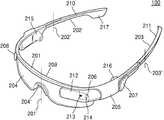
도 2는 다른 일부 실시 예에 따른 HMD 디바이스의 외형도이다.2 is an external view of an HMD device according to another exemplary embodiment.
도 2을 참조하면, HMD 디바이스(100)는 사용자(또는 착용자)의 귀와 코를 통해 사용자의 얼굴에 고정되는 안경 같은 형태로 구성될 수 있다. 그러나, HMD 디바이스(100)의 구성은 이로 제한되지 않는다. 예를 들어, HMD 디바이스(100)는 헬멧(Helmet) 구조에 부착되거나 고글(Goggles) 형태로 변형될 수 있다.Referring to FIG. 2 , the
도 2에 도시된 HMD 디바이스(100)는 렌즈 프레임(201), 측면 다리들(side-arms)(202, 203), 렌즈(204), 내장 컴퓨터(on-board computer)(205), 카메라(206), 사용자 입력부(207), 센서들(208, 209, 210), 햅틱 모듈(211), 디스플레이(212), 광 출력기(213), 마이크(214), 스피커(215, 216), 및 전원 공급부(217)를 포함할 수 있다.The
HMD 디바이스(100)에 포함되는 일부 구성 요소는 HMD 디바이스(100)에 내장되고, 다른 일부 구성 요소는 HMD 디바이스(100)의 외부에 장착될 수 있다. 예를 들어, 센서들(208, 209, 210)은 HMD 디바이스(100)에 내장될 수 있다. 디스플레이(212)는 HMD 디바이스(100)의 외부에 장착될 수 있다. HMD 디바이스(100)에 내장되는 구성 요소와 HMD 디바이스(100)의 외부에 장착되는 구성 요소는 상술한 바로 제한되지 않는다.Some components included in the
HMD 디바이스(100)에 포함되는 구성 요소는 도 2에 도시된 바로 한정되지 않는다. 예를 들어, HMD 디바이스(100)는 센서들(208, 209, 210)중 일부, 및 햅틱 모듈(211)을 포함하지 않을 수 있다. 예를 들어, HMD 디바이스(100)는 센서들(208, 209, 210)중 센서(210)만 포함하거나 도 2에 도시된 것보다 더 많은 위치에 센서들을 내장하거나 외부에 장착할 수 있다.Components included in the
렌즈 프레임(201) 및 측면 다리들(202, 203)은 플라스틱 또는/및 메탈과 같은 고체로 구성되거나 HMD 디바이스(100)에 포함되는 구성 요소들을 서로 연결시킬 수 있는 배선과 같은 물질을 포함하도록 속이 빈 플라스틱 또는/및 메탈과 같은 고체로 구성될 수 있다.The
도 2에 도시된 렌즈 프레임(201) 및 측면 다리들(202, 203)은 연결부(미 도시됨)가 없는 일체형으로 구성될 수 있다. 따라서 렌즈 프레임(201)과 측면 다리들(202, 203)은 HMD 디바이스(100)의 프레임으로 언급될 수 있다.The
렌즈 프레임(201) 및 측면 다리들(202, 203)의 구조는 도 2에 도시된 바로 제한되지 않는다. 예를 들어, HMD 디바이스(100)는 렌즈 프레임(201) 및 측면 다리들(202, 203)간에 연결부재(미 도시됨)가 있는 구조로 구성될 수 있다. 즉, HMD 디바이스(100)가 렌즈 프레임(201)과 오른쪽 측면 다리(202)간에 연결부재(미 도시됨)가 있고, 렌즈 프레임(201)와 왼쪽 측면 다리(203)간에 연결부재(미 도시됨)가 있는 구조로 구성될 경우에, 측면 다리들(202, 203)은 렌즈 프레임(201) 방향으로 접혀질 수 있다.The structures of the
HMD 디바이스(100)가 렌즈 프레임(201)의 센터(201')에 연결부재(미 도시됨)가 있고, 렌즈 프레임(201)과 오른쪽 측면 다리(202)간에 연결부재(미 도시됨)가 있고, 렌즈 프레임(201)과 왼쪽 측면 다리(203)간에 연결부재(미 도시됨)가 있고, 측면 다리들(202, 203)의 각 센터(202', 203')에 연결부재(미 도시됨)가 있는 구조로 구성될 경우에, 각 연결부재에 기초하여 렌즈 프레임(201), 및 측면 다리들(202, 203)은 내측 방향으로 접혀 HMD 디바이스(100)의 사이즈를 최소화 시킬 수 있다.The
상술한 미 도시된 연결부재들은 나사 조립 형태로 구성되거나 홈에 고리를 끼워 연결시키는 형태로 구성될 수 있으나 이로 제한되지 않는다.The above-described non-illustrated connecting members may be configured in a screw assembly type or may be configured to be connected by inserting a ring into the groove, but is not limited thereto.
측면 다리들(202, 203)은 사용자의 귀에 걸 수 있는 형태로 구성될 수 있다, 측면 다리들(202, 203)은 사용자의 머리 뒤부분 주변까지 확장되도록 구성될 수 있다. 측면 다리들(202, 203)이 사용자의 머리 뒤부분 주변까지 확장되도록 구성될 경우에, 측면 다리들(202, 203)을 사용자의 머리에 고정시킬 수 있는 밴드(미 도시됨)가 측면 다리들(202, 203)간에 추가될 수 있다. 밴드(미 도시됨)는 사용자의 머리의 사이즈에 관계없이 측면 다리들(202, 203)이 사용자의 머리에 고정되도록 탈력 밴드 형태로 구성될 수 있다.The
사용자의 귀바퀴 뒤에 접촉되는 측면 다리들(202, 203)의 내측 위치에 측면 다리들(202, 203)의 미끄러짐 또는 흘러내림을 방지할 수 있는 방지부재(미 도시됨)가 부착될 수 있다.A prevention member (not shown) capable of preventing slipping or sliding of the
렌즈 프레임(201)은 렌즈(204)가 탈착이 가능하도록 구성될 수 있다. 도 2에 도시된 렌즈(204)는 코걸이(nosepiece)(204')와 일체형으로 구성되나 이로 제한되지 않는다. 예를 들어, 렌즈 프레임(201)이 코걸이(nosepiece)와 일체형인 경우에, 후술할 도 3에 도시된 바와 같이 렌즈(204)는 오른쪽 렌즈(404)와 왼쪽 렌즈(405)로 구성될 수 있다.The
렌즈(204)는 사용자가 실 세계(Real World) 또는 물리적인 세계를 볼 수 있는 투명한 물질로 구성될 수 있다. 렌즈(204)는 디스플레이(212)를 통해 반사되는 빛을 통과시킬 수 있는 물질로 구성될 수 있다. 렌즈(204)로 사용될 수 있는 물질은, 예를 들어, 폴리카보네이트와 같은 플라스틱, 또는 유리를 포함할 수 있으나 이로 제한되지 않는다. 렌즈(104)는 빛 반사 및 눈부심 방지 코팅, 김서림 방지 코팅, 및 자외선 차단 코딩중 적어도 하나를 포함할 수 있다.The
내장 컴퓨터(205)는 유선 또는 무선으로 HMD 디바이스(100)에 연결될 수 있다. 내장 컴퓨터(205)는 렌즈 프레임(201)에 인접한 왼쪽 측면 다리(203)의 일부에 위치하나 이로 제한되지 않는다. 예를 들어 내장 컴퓨터(205)는 오른쪽 측면 다리(202)의 일부에 위치하거나 왼쪽 측면 다리(203)의 다른 일부 등 HMD 디바이스(100)의 다른 일부에 위치할 수 있다.The embedded
내장 컴퓨터(205)는, 예를 들어, 카메라(206), 사용자 입력부(207), 센서들(208, 209, 210)로부터 데이터를 수신하고, 수신된 데이터를 분석하고, 광 출력기(213)와 디스플레이(212) 및 스피커(215, 216)중 적어도 하나를 통해 HMD 디바이스(100)의 사용자에게 전달할 정보를 생성할 수 있다. 사용자에게 전달할 정보는 이미지, 텍스트, 비디오, 오디오중 적어도 하나를 포함할 수 있으나 이로 제한되지 않는다.The embedded
카메라(206)는 왼쪽 측면 다리(203)의 외측에 위치하거나 왼쪽 측면 다리(203)에 내장될 수 있다. 카메라(206)는 HMD 디바이스(100)의 다른 위치에 장착될 수 있다. 예를 들어, 카메라(206)는 오른쪽 측면 다리(202)의 일부에 위치하거나 렌즈 프레임(201)의 일부(예를 들어, 센터)에 위치할 수 있다. 카메라(206)는 스마트폰에서 사용되는 카메라나 웹캠(webcams)과 같은 소형 카메라로 구성될 수 있다. 카메라(206)는 HMD 디바이스(100)의 사용자에 의해 인지되는 실 세계의 적어도 한 부분을 캡쳐 할 수 있는 위치에 장착될 수 있다.The
사용자 입력부(207)는 사용자의 손가락에 의해 동작 가능한 터치 패드 및 사용자의 푸시 조작에 의해 동작 가능한 버튼 중 적어도 하나를 포함할 수 있으나 이로 제한되지 않는다. 사용자 입력부(207)는 왼쪽 측면 다리(203)의 일부에 위치하나 HMD 디바이스(100)의 다른 부분에 위치할 수 있다. 예를 들어, 사용자 입력부(107)는 왼쪽 측면 다리(203)의 다른 일부, 오른쪽 측면 다리(202)의 일부, 및 렌즈 프레임(201)의 일부에 위치할 수 있다.The
사용자 입력부(207)는 커맨드를 입력하기 위해 사용자에 의해 사용될 수 있다. 사용자 입력부(207)는 HMD 디바이스(100)의 전원을 온/오프 할 수 있는 온/오프 스위치를 포함할 수 있다.The
센서(208)는 HMD 디바이스(100)의 사용자의 생체 정보를 감지할 수 있는 생체 정보 감지 센서일 수 있다. 센서(208)는 렌즈 프레임(201)의 오른쪽 하단에 돌출된 형태로 설치되나 센서(208)의 설치 형태는 이로 제한되지 않는다. 예를 들어, 센서(208)는 렌즈 프레임(201)에 내장되거나 렌즈 프레임(201)상에 장착될 수 있다. 센서(208)는 HMD 디바이스(100)의 다른 임의의 한 부분에 위치할 수 있다.The
센서(208)가 이미지 센서 기반의 카메라로 구성된 경우에, 센서(208)는 사용자의 눈 충혈도, 사용자의 눈의 건조도, 사용자의 눈 깜빡임 횟수, 사용자의 눈동자의 위치, 및 사용자의 눈의 동공의 변화 등을 검출할 수 있으나 이로 제한되지 않는다.When the
센서(208)가 산소 센서, 공기 센서, 및 미세 먼지 측정 센서중 적어도 하나로 구성된 경우에, 센서(208)는 사용자의 눈의 건조도를 검출할 수 있으나 이로 제한되지 않는다.When the
센서(209)는 HMD 디바이스(100)의 주변 환경을 감지할 수 있는 주변 환경 감지 센서일 수 있다. 센서(209)는 렌즈 프레임(201)의 센터 내측에 위치하나 이로 제한되지 않는다. 예를 들어, 센서(209)는 상술한 렌즈 프레임(201)의 센터 내측이외의 렌즈 프레임(201)의 내측 일부, 렌즈 프레임(201)의 외측 일부, 측면 다리(202, 203)의 내측 일부, 및 측면 다리(202, 203)의 외측 일부중 적어도 하나의 위치에 내장되거나 외부에 장착될 수 있으나 센서(209)의 설치 위치 및 설치 구조는 상술한 바로 제한되지 않는다. 센서(209)는 HMD 디바이스(100)의 주변의 온도, 빛, 습도, 바람, 고도, 기압 등과 같은 주변 환경을 검출할 수 있는 센서로 구성될 수 있으나 검출 가능한 주변 환경은 이로 제한되지 않는다.The
센서(208)가 상술한 바와 같이 산소 센서, 공기 센서, 및 미세먼지 측정 센서중 적어도 하나로 구성되는 경우에, HMD 디바이스(100)의 주변 환경 정보는 센서(208)를 통해 감지된 신호에 기초할 수 있다. 이러한 경우에 HMD 디바이스(100)는 센서(209)를 포함하지 않을 수 있다.When the
센서(210)는 HMD 디바이스(100)의 착용상태를 감지할 수 있는 센서일 수 있다. 센서(110)는 사용자의 귀 뒤 면에 접촉되는 오른쪽 측면 다리(202) 내측에 위치하나 센서(210)의 위치는 이로 제한되지 않는다. 예를 들어, 센서(210)는 사용자의 귀 뒤 면에 접촉되는 왼쪽 측면 다리(203) 내측에 위치하거나 사용자의 귀 뒤 면에 접촉되는 전원 공급부(217) 내측에 위치할 수 있다.The
센서(210)는 예를 들어, 압력 센서로 구성될 수 있다. 센서(210)가 압력 센서로 구성되는 경우에, 센서(210)는 압력이 가해지는지 여부와 압력의 크기 등을 검출한 신호를 내장 컴퓨터(205)로 전송할 수 있다. 이에 따라 내장 컴퓨터(205)는 센서(210)로부터 수신된 센싱 값에 기초하여 HMD 디바이스(100)의 착용시간을 검출하거나 HMD 디바이스(100)를 착용한 후, 실질적으로 애플리케이션을 실행한 시간 등을 검출할 수 있다.The
햅틱 모듈(211)은 HMD 디바이스(100)의 왼쪽 측면 다리(203) 내측의 끝단에 인접한 지점에 위치하나 햅틱 모듈(211)의 설치 위치는 이로 제한되지 않는다. 예를 들어, 햅틱 모듈(211)은 오른쪽 측면 다리(202) 내측의 일부에 위치하거나 HMD 디바이스(100)의 다른 지점에 위치할 수 있다.The
햅틱 모듈(211)은 사용자가 느낄 수 있는 다양한 촉각 효과를 발생시킬 수 있는 물질로 구성될 수 있다. 예를 들어, 햅틱 모듈(211)은 진동 효과를 발생시킬 수 있는 물질, 접촉 피부 면에 자극 효과를 발생시킬 수 있는 물질, 공기의 분사 또는 흡입에 기초한 자극 효과를 발생시킬 수 있는 물질, 전극(electrode)의 접촉을 통한 자극 효과를 발생시킬 수 있는 물질, 정전기력을 이용한 자극 효과를 발생시킬 수 있는 물질, 흡열이나 발열이 가능한 소자를 이용한 냉온감 효과를 발생시킬 수 있는 물질 등 다양한 촉각 효과를 발생시킬 수 있는 물질로 구성될 수 있으나 햅틱 모듈(211)로 사용되는 물질은 이로 제한되지 않는다.The
디스플레이(212)는 HMD 디바이스(100)의 왼쪽 측면 다리(203)에 연결되어 렌즈(204) 왼쪽 상단에 위치하나 디스플레이(212)의 위치는 이로 제안되지 않는다. 예를 들어, 디스플레이(212)는 렌즈(204)의 오른쪽 센터에 위치하도록 오른쪽 측면 다리(202)와 연결되거나 렌즈(204)의 왼쪽 센터에 위치하도록 왼쪽 측면 다리(203)에 연결될 수 있다. 디스플레이(212)는 반투명 광 파장 가이드(optical waveguide)(예를 들어, 프리즘)로 구성될 수 있으나 이로 제한되지 않는다. 이에 따라 디스플레이(212)는 광 출력기(213)로부터 출력되는 광을 반사시켜 HMD 디바이스(100)의 사용자의 눈의 망막(retina)의 횡반(fovea)에 이미지를 포커싱할 수 있다.The
광 출력기(213)는 예를 들어, 미니 프로젝터로 구성될 수 있으나 이로 제한되지 않는다.The
마이크(214)는 HMD 디바이스(100)의 사용자의 음성, 및 기타 소리 등을 수신할 수 있다. 마이크(214)는 근거리 모드와 원거리 모드를 선택적으로 설정할 수 있도록 구성될 수 있다. 예를 들어, 마이크(214)를 근거리 모드로 설정할 경우에, 마이크(214)는 HMD 디바이스(100)의 사용자의 생체 정보(예를 들어, 눈의 깜박임에 기초한 정보)와 같은 기타 소리를 수신하기 위한 용도로 사용될 수 있다. 마이크(214)를 원거리 모드로 설정할 경우에, 마이크(214)는 HMD 디바이스(100)의 사용자의 음성을 수신하는 용도로 사용될 수 있다. 마이크(214)의 근거리 모드는 HMD 디바이스(100) 내측에서 발생되는 소리를 수신할 수 있는 모드이고, 마이크(214)의 원거리 모드는 HMD 디바이스(100) 외측에서 발생되는 소리를 수신할 수 있는 모드일 수 있다. 그러나 상술한 근거리 모드와 원거리 모드의 동작 범위는 다르게 설정될 수 있다.The
스피커(215, 216)는 HMD 디바이스(100)의 사용자의 귀에 장착할 수 있는 이어폰 형태로 구성될 수 있다. 스피커(215)는 HMD 디바이스(100)의 사용자의 오른쪽 귀에 장착할 수 있도록 오른쪽 측면 다리(202)의 내측에 위치한다. 스피커(216)는 HMD 디바이스(100)의 사용자의 왼쪽 귀에 장착할 수 있도록 왼쪽 측면 다리(203)의 내측에 위치할 수 있다.The
스피커(215, 216)는 도 2에 도시된 바와 같이 HMD 디바이스(100)에 고정된 형태로 장착될 수 있으나 스피커(215, 216)의 장착 형태는 이로 제한되지 않는다. 예를 들어, 스피커(215, 216)는 HMD 디바이스(100)로부터 탈착이 가능하도록 구성되어 HMD 디바이스(100)의 사용자가 선택적으로 스피커(215, 216)를 사용자의 귀에 끼울 수 있도록 구성될 수 있다.The
스피커(215, 216)가 HMD 디바이스(100)에 탈착이 가능한 경우에, 스피커(215, 216)는 사용자의 귀 뒤면에 접촉되는 각 측면 다리들(202, 203)의 내측에 위치할 수 있다. 이에 따라 사용자는 각 측면 다리들(202, 203)로부터 스피커(215, 216)를 뺀 후, 사용자의 귀에 끼울 수 있다. 이와 같이 스피커(215, 216)를 각 측면 다리들(202, 203)로부터 빼서 사용자의 귀에 끼울 경우에, 스피커(215, 216)와 HMD 디바이스(100)간에 연결선(미 도시됨)이 있을 수 있다.When the
스피커(215, 216)와 HMD 디바이스(100)간에 연결선(미 도시됨)은 스피커(215, 216)가 HMD 디바이스(100)에 장착될 경우에, HMD 디바이스(100)에 내장될 수 있으나 이로 제한되지 않는다. 스피커(215, 216)와 HMD 디바이스(100)는 근거리 무선 통신에 기초하여 무선으로 연결될 수 있다.A connection line (not shown) between the
스피커(215, 216)와 HMD 디바이스(100) 사이에 탄성 물질(예를 들어 스프링)에 기초한 연결부재(미 도시됨)가 있을 수 있다. 이러한 경우에, 탄성 물질에 기초한 연결부재는 사용자의 귀의 위치에 따라 형태가 변경될 수 있다. 예를 들어, 연결 부재는 스피커(215, 216)를 좌측 방향, 우측 방향, 상측 방향, 및 하측 방향중 적어도 하나의 방향으로 기울일 수 있도록 형태가 변경될 수 있다. 스피커(215, 216)와 HMD 디바이스(100) 사이에 탄성 물질에 기초한 연결 부재가 있을 경우에, 스피커(215, 216)와 HMD 디바이스(210)간은 유선 또는 무선으로 통신할 수 있도록 구성될 수 있다. 일부 실시 예에 따르면, 스피커(215, 216)는 골전도 스피커로 구성될 수도 있다.There may be a connecting member (not shown) based on an elastic material (eg, a spring) between the
전원 공급부(217)는 HMD 디바이스(100)의 오른쪽 측면 다리(102)의 끝단에 위치하나 전원 공급부(217)의 위치는 이로 제한되지 않는다. 예를 들어 전원 공급부(217)는 HMD 디바이스(100)의 왼쪽 측면 다리(103)의 말단에 위치할 수 있다.The
전원 공급부(217)는 HMD 디바이스(100)의 오른쪽 측면 다리(202)에 탈착이 가능하도록 구성될 수 있다. 전원 공급부(217)는 오른쪽 측면 다리(202)에 연결된 후 또는 오른쪽 측면 다리(202)로부터 분리된 후, 외부 전원 공급장치(미 도시됨)와 연결되어 충전될 수 있는 외부 전원 커넥터를 포함할 수 있다. 전원 공급부(217)는 HMD 디바이스(100)의 오른쪽 측면 다리(202)와 일체형으로 구성될 수 있다. 일체형으로 구성된 경우에도, 전원 공급부(217)는 외부 전원 공급 장치(미 도시됨)와 연결되어 충전될 수 있는 외부 전원 커넥터를 포함할 수 있다.The
도 3은 또 다른 일부 실시 예에 따른 HMD 디바이스의 외형도이다. 도 3은 외눈용 렌즈(303)를 갖는 HMD 장치(300)로서, 도 2와 같이 싱글 디스플레이 형태 또는 단안식 디스플레이 형태로 구성될 수 있다.3 is an external view of an HMD device according to another exemplary embodiment. 3 is an
도 3을 참조하면, 바람직한 다른 실시 예에 따른 HMD 장치(300)는 사용자의 한쪽 귀와 일측 코를 통해 사용자의 얼굴에 고정되는 외눈 안경 같은 형태로 구성된다. HMD 장치(300)는 헬멧(Helmet) 구조에 부착될 수 있다.Referring to FIG. 3 , the
HMD 장치(300)는 렌즈 프레임(301), 측면 다리(side-arm)(302), 렌즈(303), 내장 컴퓨터(on-board computer)(304), 카메라(305), 사용자 입력부(306), 센서들(307, 308, 309), 햅틱 모듈(310), 디스플레이(311), 광 출력기(312), 마이크(313), 스피커(314), 및 전원 공급부(315)를 포함할 수 있다.The
HMD 장치(300)에 포함되는 구성 요소는 도 3에 도시된 바로 한정되지 않는다. 예를 들어, HMD 장치(300)는 센서들(307, 308, 309)중 일부, 및 햅틱 모듈(310)을 포함하지 않을 수 있다. 예를 들어, HMD 장치(300)는 센서들(307, 308, 309)중 센서(309)만 포함하거나 도 3에 도시된 것보다 더 많은 위치에 센서들이 부착될 수 있다. HMD 장치(300)에 부착된 센서들(307, 308, 309)의 위치는 변경될 수 있다.Components included in the
렌즈 프레임(301)은 도 1에서 설명한 바와 같이 렌즈(303)를 탈부착 가능하도록 구성될 수 있다. 또한, HMD 장치(300)는 도 2에서 설명한 바와 같이 렌즈 프레임(301)와 측면 다리(302)간에 연결 부재가 있을 수 있다. 또한, HMD 장치(300)는 도 2에서 설명한 바와 같이 측면 다리(302)의 센터에 연결부재가 있을 수 있다.The
HMD 장치(300)에 포함되는 렌즈(303), 내장 컴퓨터(on-board computer)(204), 카메라(305), 사용자 입력부(306), 센서들(307, 308, 309), 햅틱 모듈(310), 디스플레이(311), 광 출력기(312), 마이크(313), 스피커(314), 및 전원 공급부(315)들은 도 2에 도시된 렌즈(204), 내장 컴퓨터(on-board computer)(205), 카메라(206), 사용자 입력부(207), 센서들(208, 209, 210), 햅틱 모듈(211), 디스플레이(212), 광 출력기(213), 마이크(214), 스피커(215, 216), 및 전원 공급부(217)과 유사하게 위치하고, 유사하게 구성될 수 있다.A
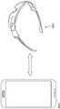
바람직한 실시 예들에서 사용되는 HMD 장치(100)는 도 4에 도시된 HMD 장치(400)와 같이 구성될 수 있다. 도 4에 도시된 HMD 장치(400)는 양안식 디스플레이 형태로 구성된다. HMD 장치(400)는 헬멧(Helmet) 구조에 부착되거나 고글 형태로 변형될 수 있다.The
도 4는 또 다른 일부 실시 예에 따른 HMD 디바이스의 외형도이다. 도 4에 도시된 HMD 장치(400)는 양안식 디스플레이 형태로 구성될 수 있다. HMD 장치(400)는 헬멧(Helmet) 구조에 부착되거나 고글 형태로 변형될 수 있다.4 is an external view of an HMD device according to another exemplary embodiment. The
도 4에 도시된 HMD 장치(400)는 렌즈 프레임(401), 측면 다리들(side-arms)(402, 403), 렌즈들(404, 405), 내장 컴퓨터(on-board computer)(406), 카메라(407), 사용자 입력부(408), 센서들(409, 410, 411), 햅틱 모듈(412), 디스플레이(413, 414), 마이크(415), 스피커(416, 417), 및 전원 공급부(418)를 포함할 수 있다.The
도 4에 도시된 HMD 장치(400)에 포함되는 렌즈 프레임(401)은 코걸이(401')와 일체형으로 구성된다. 렌즈 프레임(401)은 사각형, 타원형, 원형 등 다양한 형태로 구성될 수 있으나 렌즈 프레임(401)의 구조는 이로 제한되지 않는다. 렌즈 프레임(401)은 도 2에서 언급된 렌즈 프레임(201)와 유사한 물질로 구성될 수 있다.The
렌즈들(404, 405)은 미 도시된 광 출력기(도 2에서 언급된 프로젝터)를 통해 프로젝트되는 이미지 또는 그래픽과 같은 정보를 디스플레이 하기에 적절한 임의의 물질로 구성될 수 있다. 렌즈들(404, 405)은 HMD 장치(400)의 사용자가 렌즈들(404, 405)을 통해 볼 수 있는 실 세계와 상술한 광 출력기(미 도시됨)를 통해 프로젝트되는 이미지 또는 그랙픽과 같은 정보를 중첩시킬 수 있는 물질로 구성될 수 있다. 렌즈들(404, 405)을 구성하는 물질은 도 2에서 언급된 렌즈(204)를 구성하는 물질과 같이 플라스틱 또는 유리로 구성될 수 있으나 이로 제한되지 않는다.
도 4에 도시된 측면 다리들(side-arms)(402, 403), 내장 컴퓨터(on-board computer)(406), 카메라(407), 사용자 입력부(408), 센서들(409, 410, 411), 햅틱 모듈(412), 마이크(415), 스피커(416, 417), 및 전원 공급부(418)들은 도 2에 도시된 측면 다리들(side-arms)(202, 203), 내장 컴퓨터(on-board computer)(205), 카메라(206), 사용자 입력부(207), 센서들(208, 209, 210), 햅틱 모듈(211), 마이크(214), 스피커(215, 216), 및 전원 공급부(217)들과 일부 다른 위치에 설치되어 있으나, 그 기능이나 구성은 유사할 수 있으나 이로 제한되지 않는다.4 , side-
도 4에 도시된 디스플레이(413, 414)는 측면 다리들(402, 403) 각각의 내측 표면에 장착될 수 있는 상술한 광 출력기들(미 도시됨)에 의해 프로젝트되는 이미지 또는 그래픽과 같은 정보를 디스플레이 할 수 있다.The
도 4에 도시된 HMD 장치(400)는 렌즈(404, 405)를 디스플레이로서 동작시키도록 변형될 수 있다. 이러한 경우에 렌즈(404, 405)는 투명 디스플레이 또는 반투명 디스플레이로 구성될 수 있다. 렌즈(404, 405)가 반투명 디스플레이로 구성될 경우에, 렌즈(404, 405)는 적어도 하나의 광 웨이브 가이드(예를 들어, 프리즘), 전자발광 디스플레이(Electroluminescent Display), 또는 LCD(Liquid Crystal Display) 등으로 구성될 수 있으나 이로 제한되지 않는다.The
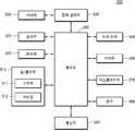
도 5는 일부 실시 예에 따른 HMD 디바이스의 회로 구조를 도시한 블록도이다.5 is a block diagram illustrating a circuit structure of an HMD device according to some embodiments.
일부 실시 예에 따른 HMD 디바이스(500)는 입/출력부(510), 메모리(520), 센서부(525), 배터리(530), 전력 관리부(535), 통신부(540), 터치 센서(550), 카메라(560), 디스플레이부(570), 렌즈(580) 및 제어부(590)를 포함할 수 있다.The
입/출력부(510)는 사용자의 입력을 수신하거나, 사용자에게 정보를 알리거나, 외부로부터 데이터를 수신하거나, 외부로 데이터를 출력하기 위한 수단을 포함한다. 입/출력부(510)는 적어도 하나의 스피커(511), 적어도 하나의 마이크(512), 적어도 하나의 버튼, 커넥터, 키패드 또는 이들의 조합을 포함할 수 있다. 다만, 본 발명의 실시 예는 이에 한정되지 아니한다.The input/
스피커(511)는 제어부(590)의 제어에 따라서 다양한 데이터에 대응되는 음향을 HMD 디바이스(500)의 외부로 출력할 수 있다. 또한, 스피커(511)는 HMD 디바이스(500)가 수행하는 기능에 대응되는 음향을 출력할 수 있다. 스피커(511)는 HMD 디바이스(500)의 적절한 위치 또는 위치들에 하나 또는 복수로 배치될 수 있다. 일부 실시 예에 따르면, 스피커(511)는 도 2에 도시된 바와 같이 이어폰(earphone)의 형태로 구현될 수도 있다.The
마이크(512)는 HMD 디바이스(100)의 외부로부터 음성(voice) 내지 음향(sound)를 수신하고, 수신된 음성(voice) 내지 음향(sound)에 기초하여 전기 신호를 생성하며, 생성된 전기 신호를 제어부(590)로 출력할 수 있다. 마이크(512)는 HMD 디바이스(100)의 적절한 위치 또는 위치들에 하나 또는 복수로 배치될 수 있다. 본 명세서 전체에서, 신호는 데이터로 대체 표기될 수 있으며, 또한 데이터는 데이터 신호로도 표기될 수 있다.The
센서부(525)는 HMD 디바이스(500)의 상태 또는 주변 환경의 상태를 검출하는 적어도 하나의 센서를 포함할 수 있다. 예를 들어, 센서부(225)는 사용자의 HMD 디바이스(500)에 대한 접근 여부를 검출하는 근접 센서, HMD 디바이스(500)의 동작(예를 들어, 회전, 가속, 감속, 진동 등)을 검촐하는 모션/방위 센서, 주변 조도를 검출하는 조도 센서, 빛의 색상이나 스펙트럼 등을 감지하는 감광 센서 또는 이들의 조합을 포함할 수 있다. 또한, 모션/방위 센서는 가속도 센서, 중력 센서, 지자기 센서, 자이로(gyro) 센서, 충격 센서, GPS, 나침반 센서(compass sensor) 및 가속도 센서 중 적어도 하나를 포함할 수 있다. 예를 들어, GPS 모듈은 지구 궤도상에 있는 복수의 GPS 위성으로부터 전파를 수신하고, GPS 위성으로부터 HMD 디바이스(500)까지의 전파도달시간(time of arrival)을 이용하여 HMD 디바이스(500)의 위치를 산출할 수 있다.The
전력 관리부(535)는 제어부(590)의 제어에 따라서 HMD 디바이스(500)에 전력을 공급할 수 있다. 전력 관리부(535)는 하나 이상의 배터리(530)와 연결될 수 있다. 또한, 전력 관리부(535)는 유선 케이블을 통해 외부의 전원 소스로부터 입력되는 전원을 HMD 디바이스(500)로 공급할 수 있다.The
통신부(540)는 유선, 무선 또는 유무선 통신부일 수 있으며, 제어부(590)로부터 데이터를 유선 또는 무선으로 외부 통신망 또는 대기를 통해 외부 장치로 전송하거나, 외부 통신망 또는 대기를 통해 전자 장치로부터 데이터를 유선 또는 무선으로 수신하고, 수신된 데이터를 제어부(590)로 전달할 수 있다. 실시 예에 따라서, 통신부(540)는 이동 통신 모듈, 무선 랜 모듈 및 근거리 통신 모듈 중 적어도 하나를 포함할 수 있다.The
이동 통신 모듈은 제어부(590)의 제어에 따라 적어도 하나의 안테나를 이용하여 이동 통신망을 통해 외부 장치와 통신을 수행할 수 있다. 이동 통신 모듈은 IP 등의 네트워크 주소 또는 전화번호를 가지는 휴대폰, 스마트폰, 태블릿 PC 또는 다른 통신 장치와 음성 통화, 화상 통화, 단문메시지(SMS) 또는 멀티미디어 메시지(MMS)를 위한 무선 신호를 송신 또는 수신할 수 있다.The mobile communication module may communicate with an external device through a mobile communication network using at least one antenna under the control of the
무선 랜 모듈은 제어부(590)의 제어에 따라 무선 AP(access point)의 주변에서 무선 AP를 통해 인터넷에 연결될 수 있다. 무선 랜 모듈은 미국전기전자학회(IEEE)의 무선 랜 규격(IEEE802.11x)을 지원할 수 있다.The wireless LAN module may be connected to the Internet through a wireless AP in the vicinity of a wireless access point (AP) under the control of the
근거리 통신 모듈은 제어부(590)의 제어에 따라 외부의 통신 장치와 무선으로 근거리 통신을 수행할 수 있다. 근거리 통신 방식은, 예를 들어, 블루투스TM(bluetoothTM), 적외선 통신(IrDA, Infrared Data Association), 와이파이 다이렉트(Wi-Fi direct) 통신, NFC(Near Field Communication) 또는 이들의 조합일 수 있다.The short-range communication module may wirelessly perform short-range communication with an external communication device under the control of the
터치 센서(550)는 적어도 하나의 터치 입력에 대응되는 신호를 제어부(590)로 전송할 수 있다. 사용자는 신체의 일부(예를 들어, 손가락) 또는 다른 터치 입력 수단을 통해 터치 센서(550)에 접촉할 수 있고, 터치 센서(550)는 이러한 사용자의 접촉을 감지함으로써 터치 입력을 수신할 수 있다. 또한, 터치 센서(550)는 접촉된 위치의 연속적인 움직임에 따른 입력(예를 들어, 드래그 입력)을 수신할 수 있다. 터치 입력 정보는 터치 좌표 및/또는 접촉 상태를 포함할 수 있다. 접촉 상태는 터치 센서(550)에 신체 등이 접촉된 마우스 다운 상태, 터치 센서(550)로부터 신체 등이 분리되는 마우스 업 상태, 또는 터치 센서(550)에 접촉된 상태로 슬라이딩하는 드래그 상태일 수 있다. 제어부(590)는 터치 입력에 기초하여 메뉴 항목 또는 아이템의 선택 또는 이동, 필기 입력 등의 사용자 입력 정보를 파악할 수 있다. 제어부(590)는 터치 입력에 대응하는 기능(예를 들어, 전화 연결, 카메라 촬영, 메뉴 선택, 메시지 작성/보기, 데이터 전송 등)을 수행할 수 있다.The
다만, 본 명세서에서, 터치 입력은 터치 센서(550)와 터치 입력 수단의 접촉을 이용한 입력에 한정되지 않는다. 터치 입력은 비접촉(예를 들어, 터치 센서(550)와 터치 입력 수단이 서로 이격된 상태)을 이용한 입력을 포함할 수 있다. 이러한 비접촉을 이용한 입력은 호버링(hovering) 입력으로 언급될 수도 있다.However, in this specification, the touch input is not limited to an input using a contact between the
터치 센서(550)는 저항막(resistive) 방식, 정전용량(capacitive) 방식, 적외선(infrared) 방식, 초음파 (Acoustic wave) 방식, 전자기 공지(Electromagnetic resonance: EMR) 또는 이들의 조합 등으로 구형될 수 있다.The
카메라(560)는 렌즈계 및 이미지 센서를 포함하고, 플래쉬 등을 더 포함할 수 있다. 카메라(560)는 렌즈계를 통해 입력되는(또는 촬영되는) 광을 전기적인 이미지 신호로 변환하고, 변환된 이미지 신호를 제어부(590)로 출력할 수 있다. 사용자는 카메라(560)를 이용하여 동영상 또는 정지 영상을 촬영할 수 있다. 또한, 카메라(560)는 사용자의 모션 또는 제스쳐를 통한 입력을 수신하기 위해 이용될 수도 있다.The
렌즈계는 외부로부터 입력된 광을 수렴시킴으로써 피사체의 이미지를 형성할 수 있다. 렌즈계는 적어도 하나의 렌즈를 포함하며, 각 렌즈는 볼록 렌즈, 비구면 렌즈 등일 수 있다. 렌즈계는 그 중심을 지나는 광축(optical axis)에 대해 대칭성을 가지며, 광축은 렌즈계의 중심축으로 정의될 수 있다. 이미지 센서는 렌즈계를 통해 입력된 외부 광에 기초하여 형성된 광학적 이미지를 전기적 이미지 신호로 변환할 수 있다. 이미지 센서는 MΧN 행렬(matrix) 구조로 배치된 복수의 화소(pixel) 유닛을 구비할 수 있다. 화소 유닛은 포토다이오드 및 복수의 트랜지스터들을 포함할 수 있다. 화소 유닛은 입력된 광에 의해 생성된 전하를 축적하고, 축적된 전하에 의한 전압은 입력된 광의 조도를 나타낼 수 있다. 정지 이미지 또는 동영상을 구성하는 한 이미지를 처리하는 경우에 있어서, 이미지 센서로부터 출력되는 이미지 신호는 화소 유닛들로부터 출력되는 전압들(즉, 화소 값들)의 집합으로 구성되고, 이미지 신호는 하나의 프레임(즉, 정지 이미지)을 나타낼 수 있다. 또한, 프레임은 MΧN 화소로 구성될 수 다. 이미지 센서로 CCD(charge-coupled device) 이미지 센서, CMOS(complementary metal-oxide semiconductor) 이미지 센서 등이 사용될 수 있다.The lens system may form an image of a subject by converging light input from the outside. The lens system includes at least one lens, and each lens may be a convex lens, an aspherical lens, or the like. The lens system has symmetry with respect to an optical axis passing through the center, and the optical axis may be defined as the central axis of the lens system. The image sensor may convert an optical image formed based on external light input through the lens system into an electrical image signal. The image sensor may include a plurality of pixel units arranged in an MΧN matrix structure. The pixel unit may include a photodiode and a plurality of transistors. The pixel unit may accumulate electric charges generated by the input light, and the voltage by the accumulated electric charge may represent the illuminance of the input light. In the case of processing one image constituting a still image or moving image, an image signal output from an image sensor is composed of a set of voltages (ie, pixel values) output from pixel units, and the image signal is one frame (ie, still images). Also, a frame can be composed of MΧN pixels. As the image sensor, a charge-coupled device (CCD) image sensor, a complementary metal-oxide semiconductor (CMOS) image sensor, or the like may be used.
이미지 센서는 제어부(590)로부터 수신한 제어 신호에 따라 이미지 센서의 전체 화소들 또는 전체 화소 중에서 관심 영역의 화소들만을 작동할 수 있다. 화소들로부터 출력되는 이미지 데이터는 제어부(590)로 출력될 수 있다.The image sensor may operate all pixels of the image sensor or only pixels of an ROI among all pixels according to a control signal received from the
제어부(590)는 카메라(560)로부터 입력되는 이미지, 메모리(520)에 저장된 이미지, 또는 메모리(520)에 저장된 데이터를 이용하여 제어부(590)에 의해 구성된 영상을 프레임(frame) 단위로 처리할 수 있다. 제어부(590)는 영상의 프레임을 디스플레이부(570)를 통해서 외부로 출력하거나, 메모리(520)에 저장할 수 있다. 본 명세서에서, 디스플레이부(570)를 통해 출력되는 영상은 동영상 이나 정지 화상 등의 시각적 콘텐트 또는 GUI(Graphic User Interface) 등을 의미할 수 있다.The
디스플레이부(570)는 실시 예에 따라서 다양한 형태로 구현될 수 있다. 예를 들어, 디스플레이부(570)는 광학계를 이용하여 사용자의 망막에 영상의 상이 맺히도록 함으로써 영상을 디스플레이할 수 있다. 또는, 디스플레이부(570)는 투명 디스플레이를 포함하고, 투명 디스플레이 상에 영상을 디스플레이할 수도 있다.The
일부 실시 예에 따른 렌즈(580)는 도 1에 도시된 바와 같이 HMD 디바이스(500)로부터 탈착가능한 구조로 구비될 수 있다. 즉, 렌즈(580)는 HMD 디바이스(500)에 포함되지 않을 수 있으며, HMD 디바이스(580)는 렌즈(580)를 대체하여 렌즈(580)를 부착하기 위한 구조를 포함할 수도 있다. 사용자는 렌즈(580)를 교체함으로써 HMD 디바이스(500)의 렌즈(580)의 색상을 변경할 수 있다. 또는, 다른 일부 실시 예에 따른 렌즈(580)는 제어부(590)의 제어에 따라 투과율 또는 색상이 변경될 수 있는 스마트 윈도우일 수 있다.The
도 6은 일부 실시 예에 따른 HMD 디바이스(600)가 영상을 디스플레이하는 방법을 도시한 개념도이다. 일부 실시 예에 따른 HMD 디바이스(600)는 광학계를 포함하는 디스플레이부(570)를 포함할 수 있다. 일부 실시 예에 따른 디스플레이부(570)는 렌즈(580)를 투과하여 사용자(1)의 눈(610)의 망막에 상이 맺히도록 함으로써 영상을 디스플레이할 수 있다.6 is a conceptual diagram illustrating a method of displaying an image by the
도 7은 다른 일부 실시 예에 따른 HMD 디바이스의 일부분을 도시한 외형도이다.7 is an external view illustrating a portion of an HMD device according to another exemplary embodiment.
HMD 디바이스(500)는 렌즈(580)를 고정할 수 있는 프레임(720)을 포함할 수 있다. 일부 실시 예에 따르면, 프레임(720)은 두 개의 프레임이 힌지(722)에 의현 연결된 구조를 가질 수 있다. 프레임(720)의 내측면에는 프레임(720) 내에 배치된 디스플레이부에 포함된 프로젝터로부터 출력되는 투사광(710)이 프레임(720)의 외부로 출력되는 통로가 되는 개구(711)가 배치될 수 있다. 여기서, 개구(711)에는 외부로부터의 먼지가 프레임(720) 내부로 유입되는 것을 차단하기 위한 유리나 투명한 플라스틱 등이 구비될 수 있다.The
또한, 프레임(720)의 내측면에 적어도 하나의 스피커(211)가 배치될 수 있다.In addition, at least one
프로젝터는 가상 이미지를 형성하기 위한 투사 광(710)을 출력하고, 프로젝터로부터 출력되는 투사 광(710)은 렌즈(580)에 의해 지속 및 반사되고, 집속 및 반사된 투사 광(730)은 사용자의 눈(610)의 망막에 가상 이미지를 형성할 수 있다. 여기서, 집속은 광을 모으는 것을 의미할 수 있다. 집속은 광을 한 점에 모으는 수렴이나, 광의 빔 스팟을 감소시키는 것을 포함할 수 있다. 반사된 투사 광(730)은 눈(610)의 수정체 또는 동공에 수렴할 수 있다. HMD 디바이스는 사용자의 두 눈에 각각 가상 이미지를 형성하기 위하여, 복수개의 프로젝터를 이용할 수도 있다.The projector outputs the
도 8은 일부 실시 예에 따른 디스플레이부의 구조를 도시한 개념도이다. 보다 상세하게는, 도 8은 디스플레이부가 프로젝터를 포함하는 경우, 프로젝터의 구조를 도시한 개념도이다.8 is a conceptual diagram illustrating a structure of a display unit according to some exemplary embodiments. More specifically, FIG. 8 is a conceptual diagram illustrating a structure of a projector when the display unit includes a projector.
디스플레이부(570)가 프로젝터를 포함하는 경우, 디스플레이부(570)는 광원(810), 광원(810)으로부터 출력된 광을 통해서 표시 소자(840)를 조면하는 조면 광학계(820), 조명 광학계(820)를 투과한 광을 반사하는 미러(830), 미러(830)에 의해 반사된 광을 다시 픽셀 단위로 반사하여 가상 이미지를 형성하는 표시 소자(840) 및 표시 소자(840)로부터 반사된 광을 외부로 투사하는 투사 광학계(850)를 포함할 수 있다.When the
조명 광학계(820)는 X 축과 평행한 제 1 광축(571)을 기준으로 배치될 수 있다. 조명 광학계(820)는 적어도 하나의 시준화 렌즈, 적어도 하나의 필터, 적어도 하나의 등화 렌즈, 집광 렌즈 또는 이들의 조합을 포함할 수 있다.The illumination
조명 광학계(820)의 광학 소자들(렌즈, 프리즘, 또는 필터 등)은 제 1 광축(571)을 기준으로 정렬될 수 있다. 통상적으로 광축은 광축을 중심으로 광학계를 회전시켜도 광학적으로 광학계에 변화가 발생하지 않는 축을 의미할 수 있다. 광축에 정렬된다는 것은 광학계를 구성하는 광학 소자의 곡률 중심이 광축에 위치하거나, 광학 소자의 대칭점(즉, 대칭 중심) 또는 중심점이 광축에 위치하는 것을 의미할 수 있다.Optical elements (lenses, prisms, filters, etc.) of the illumination
광원(810)은 제 1 광축(571)을 따라 진행하는 광을 출력할 수 있다. 예를 들어, 백색광, 원색광(예를 들어, 청색광이나 녹색광 등), 또는 원색광들의 조합을 출력하는 적어도 하나의 LED가 광원(810)으로 사용될 수 있다.The
조명 광학계(820)는 광원(810)으로부터 입력된 광을 시준화, 필터링 및/또는 집속 처리하고, 처리된 광을 미러(830)로 출력할 수 있다.The illumination
미러(830)는 조명 광학계(820)를 투과하여 입력된 광을 표시 소자(840) 측으로 반사할 수 있다. 미러(830)는 기판 상에 반사도가 높은 유전체 층 또는 금속 층을 증착한 구조를 가질 수 있다.The
표시 소자(840)는 제어부(590)로부터 입력된 데이터에 기초하여 픽셀 단위로 이미지를 표시할 수 있다. 표시 소자(840)는 기 설정된 해상도에 대응되는 픽셀 소자들을 구비할 수 있다. 표시 소자(840)는 픽셀 소자들의 온/오프 구동을 통해 이미지를 표시한다. 예를 들어, MxN(예를 들어, 1280x720, 854x480 등) 행렬 구조로 배열된 마이크로 미러들을 포함하는 DMD(Digital Micro-Mirror Device)가 표시 소자(840)로서 이용될 수 있다. 각 마이크로 미러는 구동 신호에 따라 온 상태에 대응하는 위치와 오프 상태에 대응하는 위치로 회전할 수 있다. 각 마이크로 미러는 온 상태일 때 외부에 표시될 수 있는 각도로 입사된 광을 반사하고, 오프 상태일 때 외부에 표시되지 않는 각도로 입사된 광을 반사할 수 있다.The
투사 광학계(850)는 Y 축과 평행한 제 2 광축(572)을 기준으로 배치될 수 있다. 투사 광학계(850)는 릴레이 렌즈(relay lens, 860) 및 투사 렌즈(projection lens, 870)를 포함할 수 있다. 릴레이 렌즈(860) 및 투사 렌즈(870)는 제 2 광축(572)에 정렬될 수 있다.The projection
릴레이 렌즈(860)는 오버필(overfill)을 감안하여 미러(830)로부터 반사된 광이 표시 소자(840)로 정합되도록 할 수 있다. 즉, 릴레이 렌즈(860)는 상기 표시 소자(840)의 픽셀 소자들이 차지하는 면적보다 큰 면적에 미러(830)로부터 반사된 광이 입사되도록 할 수 있다.The
또한, 릴레이 렌즈(860)는 표시 소자(840)로부터 반사된 광을 수신하고, 광의 빔 면적을 감소시켜서 출력할 수 있다. 표시 소자(840)로부터 반사된 광은 빔 면적(beam spot size)이 크기 때문에, 투사 렌즈(870)로 광이 전달되지 못하는 광손실이 발생할 수 있다. 릴레이 렌즈(860)는 표시 소자(840)로부터 반사된 광을 집광하여 빔 면적을 줄임으로서, 투사 렌즈(870)에 더 많은 양의 광이 전달되도록 할 수 있다.In addition, the
투사 렌즈(870)는 릴레이 렌즈(860)를 통과한 광을 수신하고, 수신된 광을 시준화 또는 집속하여 외부로 투사할 수 있다.The
도 9는 일부 실시 예에 따라 색상 또는 투과율을 변경할 수 있는 렌즈의 구성 및 기능을 설명하기 위한 개념도이다.9 is a conceptual diagram illustrating a configuration and function of a lens capable of changing a color or transmittance according to some embodiments.
일부 실시 예에 따른 렌즈(580)는 색상 또는 투과율을 변경할 수 있다. 일부 실시 예에 따른 렌즈는 투과율 제어가 가능한, 즉 인가 신호에 따라 색상 또는 투과율이 변화되는 글래스(581) 및 오목 거울로서 기능하는 홀로그래픽 광소자(holographic optical element; HOE, 582)를 포함할 수 있다.The
렌즈(580)는 외부로부터 입력된 주변 광(911)을 투과시키고, 디스플레이부(570)에서 출력된 광(921)을 반사 및 집속할 수 있다.The
투과된 주변 광(912) 및 렌즈(580)에 의해 반사된 광(921)은 사용자의 눈(610)에 입력되고, 눈(610)의 망막(613)에는 주변 광(912)에 의한 주변 환경의 이미지(910)와 디스플레이된(반사광에 의한) 영상(920)이 중첩되어 형성될 수 있다. 즉, 사용자는 주변 환경의 이미지(910)와 디스플레이된 영상(920)이 중첩된 이미지를 보게 된다. 사용자에게 디스플레이된 영상(920)은 주변 환경의 이미지(910) 상의 투명한 층에 떠 있는 것으로 인지될 수 있다. 디스플레이된 영상(920)은 전화, 연락처, 메시지, 메인 메뉴 등과 같은 메뉴나 아이콘 등을 포함하는 GUI나 정지 화상이나 동영상 등을 포함하는 컨텐츠 영상을 포함할 수 있다. 도 9에서는 디스플레이된 영상(920)이 디스플레이된 영역이 불투명하게 표시되어 있으나, 사용자가 영상(920)이 디스플레이된 영역 내에서 주변 환경의 영상(910)을 볼 수 있도록 표시될 수 있다. 즉, 영상(920)이 디스플레이된 영역 내의 투명도는 실시 예에 따라서 변경될 수 있다.The transmitted
디스플레이부(570)로부터 출력된 광(921)은 파장(λ)을 가지는 평행광(즉, 시준화된 광)일 수 있다. 광(921)은 홀로그래픽 광소자(582)의 법선과 각도(θ)를 이루도록 홀로그래픽 광소자(582)에 입사될 수 있다. 홀로그래픽 광소자(582)는 파장 선택성을 가지는 소자일 수 있다. 홀로그래픽 광소자(582)는 파장(λ)의 광(즉, 본 예시에서 광(921)은 반사 및 집속하며, 파장(λ)과 다른 파장의 광(즉, 본 예시에서 주변 광(911))은 수렴시키지 않고 그대로 투과시킬 수 있다.The light 921 output from the
홀로그래픽 광소자(582)는 입력된 광(921)을 반사 및 집속할 수 있다. 또한, 홀로그래픽 광소자(582)는 홀로그래픽 광소자(582)로부터 반사된 광(922)은 홀로그래픽 광소자(582)로부터 특정 거리, 즉 아이 릴리프(eye relief)만큼 떨어져 위치한 눈(610)의 위치에 수렴될 수 있다. 바람직하게는 반사된 광(922)은 눈(610)의 동공(611) 내지 수정체(612)의 위치에 수렴될 수 있다. 여기서, 수렴되는 광(922)은 수렴각 또는 시야각(Φ)을 가질 수 있다. 수정체(612)는 눈(610)에 입사되는 광의 초점을 조절하는 기능을 하며, 투과된 주변 광(912)은 동공(611) 내지 수정체(612)의 위치에 수렴되므로, 수정체(612)에 의해 수렴되지 않고 망막(613)에 투사되어 영상(920)을 형성할 수 있다.The holographic
홀로그래픽 광소자(582)에 입사되는 광(921)이 평행 관으로 예시하고 있으나, 이에 한정되지 않는다. 홀로그래픽 광소자(582)에 의해 반사된 광(922)이 동공(611) 내지 수정체(612)의 위치에 수렴하는 경우 광(921)은 형행 광이 아닌 발산 광 또는 수렴 광일 수 있다.The light 921 incident on the holographic
HMD 디바이스를 착용한 사용자가 주변 환경의 실제 물체를 보기 위하여 눈의 초점을 맞추는 경우, HMD 디바이스에 의해 디스플레이되는 영상(가상 물체 또는 가상 객체)은 사용자의 망막에 선명하게 형성되지 않는 문제점이 발생될 수 있다. 이 경우, 사용자가 실제 물체와 가상 물체를 동시에 선명하게 보지 못하므로, 증강 현실의 효과를 얻기 어렵다. 또한, 실제 물체와 디스플레이되는 영상 사이의 초점 불일치 문제는 양안의 시선 수렴과 단안의 초점 조절 사이의 불일치로 인한 사용자의 피로감을 증가시킬 수 있다.When a user wearing an HMD device focuses his eyes to see a real object in the surrounding environment, an image (virtual object or virtual object) displayed by the HMD device may not be clearly formed on the user's retina. can In this case, since the user cannot clearly see the real object and the virtual object at the same time, it is difficult to obtain the effect of the augmented reality. In addition, the problem of focus mismatch between the real object and the displayed image may increase user fatigue due to mismatch between binocular gaze convergence and monocular focus adjustment.
일부 실시 예에 따른 HMD 디바이스는 가상 이미지를 형성하는 투사 광을 동공 내지 수정체의 위치, 또는 그에 근접한 위치에 수렴시킴으로써, 수정체에 의한 투사 광의 초점 변화량을 최소화할 수 있다. 투사 광이 동공 내지 수정체의 위치에 수렴하는 경우, 투사 광은 수정체의 작용에 관계 없이 망막에 직접 투사될 수 있다. 망막에 투사된 영상은 수정체의 초점 조절과 수정체 등에 의한 수차와 무관하게 선명한 영상으로 사용자에 의해 인지될 수 있다.The HMD device according to an exemplary embodiment may minimize the amount of change in focus of the projected light by the lens by converging the projection light forming the virtual image to the position of the pupil or the lens or a position close thereto. When the projection light converges on the position of the pupil or the lens, the projection light can be projected directly onto the retina regardless of the action of the lens. The image projected onto the retina can be recognized by the user as a clear image regardless of focus adjustment of the lens and aberration caused by the lens.
홀로그래픽 광소자(582)는 동공(611) 내지 수정체(612)와 홀로그래픽 광소자(582) 사이의 거리에 해당하는 초점거리를 가질 수 있다.The holographic
도 10은 일부 실시 예에 따른 HMD 디바이스의 렌즈에 포함된 글래스(581)의 구성을 도시한 개념도이다. 일부 실시 예에 따른 글래스(581)는 제어부(590)에 의해 인가되는 신호 또는 전압에 의해 투과율 내지 색상이 변화될 수 있다.10 is a conceptual diagram illustrating a configuration of a
전기 변색(Electrochoromic) 글래스, SPD(Suspended Particle Device), LC(Liquid Crystal)등이 글래스(581)로 이용될 수 있다. 또는, 경우에 따라서, 신호 인가에 따른 능동 제어가 아닌 빛의 파장이나 온도 변화에 따라서 투과율이 변화되는 광호변성(Photochromic) 글래스나 감열 변색(Thermochromic) 글래스가 글래스(851)로 이용될 수도 있다.Electrochromic glass, SPD (Suspended Particle Device), LC (Liquid Crystal), etc. may be used as the
글래스(581)는 다양한 방법으로 제작될 수 있다. 예를 들어, 유리에 투과율 조절이 가능한 물질을 도포하거나, 투과율 조절이 가능한 얇은 필름(Thin Film)을 유리에 부착함으로써 글래스(581)가 제작될 수 있다.The
이하의 도 10에 대한 설명에서는 전기 변색 글래스를 글래스(581)로 이용하는 경우에 대하여 설명한다.In the following description of FIG. 10 , a case in which electrochromic glass is used as the
글래스(581)는 절연성의 제 1 및 제 2 기판(1010, 1015)과, 제 1 기판(1010)의 상면에 적층된 도전성의 제 1 전극(1020)과, 제 2 기판(1015)의 하면에 적층된 도전성의 제 2 전극(1025)과, 제 1 및 제 2 기판(1010, 1015)을 이격시키고 그 사이의 공간을 밀봉하는 절연성의 스페이서(1030)와, 제 1 및 제 2 기판(1015) 사이의 공간에 충진된 전기 변색 층(1040) 및 전해질 1050)을 포함할 수 있다.The
각 기판(1010, 1015)은 투명 유리 또는 플라스틱으로 만들어질 수 있다. 예를 들어, 플라스틱은 폴리아크릴레이드, 폴리에틸렌에테르프탈레이트, 폴리에텔린나프탈레이트, 폴리 카보네이트, 폴리아릴레이트, 폴리에테르이미드, 폴리에테르술폰 및 폴리 이미드 중 적어도 하나를 포함할 수 있다.Each of the
제 1 전극(1020)은 투명 도전체로 만들어질 수 있다. 예를 들어, 제 1 전극(1020)은 인듐 틴 옥사이드(indium tin oxide, ITO), 불소 함유 틴 옥사이드(fluorine tin oxide, FTO) 또는 안티몬 함유 옥사이드(antimony doped tin oxide, ATO)와 같은 무기 도전성 물질이나 폴리아세틸렌 또는 폴리티오펜과 같은 유기 도전성 물질을 포함할 수 있다.The
제 2 전극(1025)은 투명 또는 불투명의 도전성 물질로 만들어질 수 있다. 예를 들어 제 2 전극(1025)은 인듐 틴 옥사이드(ITO), 불소 함유 틴 옥사이드(FRO), Al과 같은 금속, 안티몬 함유 틴 옥사이드(antimony doped tin oxide, ATO) 또는 이들의 조합을 포함할 수 있다.The
제 1 전극(1020) 상에 전기 변색 물질을 포함한 전기 변색 층(1040)이 배치될 수 있다. 전기 변색 층(1040)은 제 1 전극(1020) 상에 필름(film) 형태로 배치될 수 있다. 다만 이에 한정되지 아니한다.An
제 1 기판(1010)과 제 2 기판(1015)은 스페이서(1030)에 고정될 수 있다. 제 1 기판(1010)과 제 2 기판(1015) 사이에는 전해질(1050)이 채워질 수 있다. 전해질(1050)은 전기 변색 물질과 반응하는 산화/환원 물질을 공합할 수 있다. 전해질(1050)은 액체 전해질 또는 고체 고분자 전해질일 수 있다. 액체 전해질로는, 예를 들어, LiOH 또는 LiClO4 등의 리튬 염, KOH와 같은 포타슘 염 및 NaOH와 같은 소듐 염 등이 용매에 용해되어 있는 용액이 사용될 수 있다. 고체 전해질로는, 예를 들어, 폴리(2-아크릴아미노-2-메틸프로판 술폰산)(poly(2-acrylamino-2- methylpropane sulfonic acid)), 폴리에틸렌 옥사이드(poly ethylene oxide) 등이 사용될 수 있다. 다만, 이에 한정되는 것은 아니다.The
전기 변색 층(1040)을 이루는 물질, 즉 전기 변색 물질은 금속과, 금속과 배위를 형성할 수 있는 작용기를 가지는 유기 화합물이 결합된 금속-유기 복합재를 포함할 수 있다. 금속은 경금속, 전이 금속, 란타나이드 금속, 알칼리 금속 또는 이들의 조합을 포함할 수 있다. 예를 들어, 금속은 베릴륨(Be), 바륨(Ba), 구리(Cu), 아연(Zn), 세륨(Ce), 마그네슘(Mg), 알루미늄(Al), 티타늄(Ti) 또는 이들의 조합을 포함할 수 있다. 또한, 예를 들어, 작용기는 카르복실기(carboxyl group), 피리딘기(pydidine group), 이미다졸기(imidazole group) 또는 이들의 조합을 포함할 수 있다. 또한, 예를 들어, 유기 화합물은 비올로겐(viologen) 유도체, 안트라퀴논(anthraquinone) 유도체 또는 이들의 조합을 포함할 수 있다.The material constituting the
도 11은 다른 일부 실시 예에 따라 HMD 디바이스가 영상을 디스플레이하는 방법을 도시한 개념도이다.11 is a conceptual diagram illustrating a method of displaying an image by an HMD device according to another exemplary embodiment.
다른 일부 실시 예에 따르면, 도 11의 (a)와 같이 디스플레이부(570)는 렌즈(580)와 사용자의 눈 사이에 위치하도록 배치될 수도 있다. 디스플레이부(570)는 빛이 투과될 수 있는 투명 디스플레이(transparent display)를 이용하여 구성될 수 있다.According to another exemplary embodiment, as shown in (a) of FIG. 11 , the
주변 환경에 의해 발생된 광(1110-1)은 렌즈(580) 및 디스플레이부(570)를 투과하여 사용자의 눈에 입사될 수 있으며, 디스플레이부(570)에 의해 발생된 광(1120-1)은 렌즈(580)를 투과하지 않고 바로 사용자의 눈으로 입사될 수 있다.The light 1110 - 1 generated by the surrounding environment may pass through the
또는, 도 11의 (b)와 같이 렌즈(580)가 디스플레이부(570)와 렌즈(580) 사이에 위치되도록 배치될 수도 있다. 이 경우, 주변 환경에 의해 발생된 광(1110-2)은 렌즈(580) 및 디스플레이부(570)를 투과하여 사용자의 눈에 입사될 수 있다. 디스플레이부(570)에 의해 발생된 광(1120-2)은 렌즈(580)를 투과하여 사용자의 눈으로 입사될 수 있다. 이 경우, 주변 환경에 의해 발생된 광(1110-2)과 디스플레이부(570)에 의해 발생된 광(1120-2)이 모두 렌즈(580)를 투과하여 사용자의 눈에 입사되므로, 이 경우 HMD 디바이스는 디스플레이부(570)에 의해 발생된 광이 렌즈(580)를 투과하여 사용자에게 인식되는 색상을 고려하여 영상을 수정할 수 있다.Alternatively, as shown in (b) of FIG. 11 , the
또는, 도 11의 (c)와 같이 디스플레이부(570)와 렌즈(580)는 일체로 구성된 디스플레이부/렌즈(570-1)일 수 있다. 이 경우, 디스플레이부/렌즈(570-1)의 색상 내지 투명도가 제어될 수 있으며, 영상이 디스플레이될 수 있는 스마트 윈도우(smart window)로 구성될 수 있다. 주변 환경에 의해 발생된 광(1110-3)은 디스플레이부/렌즈(570-1)를 투과하여 사용자의 눈에 입사될 수 있다. 또한, 디스플레이부/렌즈(570-1)에서 발생된 광(1120-3)은 사용자의 눈에 직접 입사될 수 있다.Alternatively, as shown in (c) of FIG. 11 , the
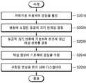
도 12는 일부 실시 예에 따라 HMD 디바이스가 영상을 디스플레이하는 프로세스를 도시한 순서도이다.12 is a flowchart illustrating a process in which an HMD device displays an image, according to some embodiments.
HMD 디바이스는 렌즈에 대한 색상 정보를 획득할 수 있다(S1210). 렌즈의 색상 정보는 HMD 디바이스가 렌즈의 색상을 식별하기 위한 식별 정보를 의미할 수 있다. 예를 들어, 렌즈의 색상 정보는 렌즈의 색상을 나타내는 RGB 값일 수 있다. 색상 정보는 실시 예에 따라 변형될 수 있다. 예를 들어, 일부 실시 예에 따르면 색상 정보는 렌즈 자체의 색상을 지시하는 정보일 수도 있다. 또는 다른 일부 실시 예에 따르면 색상 정보는 사용자에게 HMD 디바이스에 의해 디스플레이된 영상 주변의 배경의 색상으로 인식되는 색상을 지시할 수 있다. 이 경우, HMD 디바이스에 구비된 감광 센서를 이용하여 렌즈를 투과한 광의 색상을 검출함으로써, HMD 디바이스는 배경의 색상으로 인식되는 색상을 지시하는 색상 정보를 획득할 수 있다. 이 경우, 배경의 색상으로 인식되는 색상을 지시하는 색상 정보는 영상 표시 영역의 색상 정보로 언급될 수도 있다.The HMD device may acquire color information about the lens ( S1210 ). The color information of the lens may mean identification information for the HMD device to identify the color of the lens. For example, the color information of the lens may be an RGB value indicating the color of the lens. The color information may be modified according to an embodiment. For example, according to some embodiments, the color information may be information indicating the color of the lens itself. Alternatively, according to some other exemplary embodiments, the color information may indicate a color recognized as a background color around an image displayed by the HMD device to the user. In this case, by detecting the color of the light passing through the lens using a photosensitive sensor provided in the HMD device, the HMD device may obtain color information indicating a color recognized as a color of the background. In this case, color information indicating a color recognized as a background color may be referred to as color information of an image display area.
HMD 디바이스가 렌즈에 대한 색상 정보를 획득하는 방법은 다양한 방법을 이용하여 구현될 수 있다. 예를 들어, 렌즈가 교체 가능한 경우, HMD 디바이스는 렌즈가 교체되었을 때, 교체된 렌즈의 색상 정보를 획득할 수 있다. 또한, 다른 예를 들면, 렌즈가 HMD 디바이스의 제어부의 제어에 따라서 투과율 내지 색상을 변경할 수 있는 스마트 윈도우인 경우, HMD 디바이스는 렌즈의 색상을 제어할 수 있으므로 렌즈의 현재 색상을 알 수 있다.A method for the HMD device to obtain color information about a lens may be implemented using various methods. For example, when the lens is replaceable, the HMD device may acquire color information of the replaced lens when the lens is replaced. Also, as another example, when the lens is a smart window capable of changing transmittance or color according to the control of the controller of the HMD device, the HMD device can control the color of the lens, so that the current color of the lens can be known.
이후, HMD 디바이스는 S1210 단계에서 획득된 색상 정보에 기초하여 영상을 수정하고, 수정된 영상을 디스플레이부를 통해서 디스플레이할 수 있다(S1220). 예를 들어, HMD 디바이스가 텍스트를 포함하는 영상을 디스플레이하고자 할 때, 획득된 렌즈의 색상 정보가 노랑색을 지시하는 경우, HMD 디바이스는 텍스트를 도 33의 보색표에 기초하여 노랑색의 보색인 남색으로 수정하고, 남색으로 수정된 텍스트를 디스플레이부를 통해서 디스플레이할 수 있다.Thereafter, the HMD device may correct the image based on the color information obtained in step S1210 and display the corrected image through the display unit ( S1220 ). For example, when the HMD device intends to display an image including text, if the acquired lens color information indicates yellow, the HMD device converts the text to indigo, which is a complementary color of yellow, based on the complementary color table of FIG. 33 . The corrected, indigo-colored text may be displayed through the display unit.
렌즈가 HMD 디바이스에 탈착 가능하거나 HMD 디바이스가 렌즈의 색상을 제어할 수 있는 경우, HMD 디바이스는 S1210 단계를 통해서 렌즈의 색상 정보를 획득할 수 있다. 그러나 렌즈가 HMD 디바이스에 일체로 구성되며, 렌즈의 색상이 변화될 수 없는 경우, 렌즈의 색상 정보는 미리 설정되어 있을 수 있다. 즉, 고정된 색상의 렌즈가 HMD 디바이스와 일체로 구성된 경우, HMD 디바이스는 미리 결정된 렌즈의 색상 정보에 기초하여 영상의 색상을 보정할 수 있다. 예를 들어, HMD 디바이스에 청색 렌즈가 고정되어 있는 경우, HMD 디바이스는 별도로 렌즈에 대한 색상 정보를 획득하지 않고 영상의 색상을 청색의 보색인 빨강으로 수정하고, 수정된 영상을 디스플레이할 수 있다.When the lens is detachable from the HMD device or the HMD device can control the color of the lens, the HMD device may acquire color information of the lens through step S1210. However, when the lens is integrally formed with the HMD device and the color of the lens cannot be changed, color information of the lens may be preset. That is, when the fixed color lens is integrally configured with the HMD device, the HMD device may correct the color of the image based on predetermined lens color information. For example, when a blue lens is fixed to the HMD device, the HMD device may correct the color of the image to red, which is a complementary color of blue, and display the corrected image without separately acquiring color information about the lens.
도 13은 일부 실시 예에 따라 영상이 보정되고 디스플레이되는 구조를 도시한 개념도이다.13 is a conceptual diagram illustrating a structure in which an image is corrected and displayed according to some embodiments.
일부 실시 예에 따른 HMD 디바이스는 색상 보정 모듈(1330)을 포함할 수 있다. 색상 보정 모듈(1330)은 렌즈의 색상 정보(1310)와 원본 이미지(1320)에 기초하여 원본 이미지(1320)로부터 색상을 변경한 보정 이미지(1330)를 출력할 수 있다. 여기서, 일부 실시 예에 따른 색상 보정 모듈(1330)은 제어부(590)를 이용하여 구현 될 수 있다. 예를 들어, 색상 보정 모듈(1330)은 보정 이미지(133)를 생성하기 위한 프로그램이 로딩된 프로세서를 포함할 수 있다.The HMD device according to some embodiments may include a
색상 보정 모듈(1330)은 실시 예에 따라서 원본 이미지(1320)를 다양한 방법으로 수정할 수 있다. 예를 들어, 원본 이미지(1320)에 텍스트가 포함되어 있는 경우, 색상 보정 모듈(1330)은 렌즈의 색상의 보색(complementary color)으로 텍스트가 표시되도록 원본 이미지(1320)를 수정할 수 있다.The
다만, 색상 보정 모듈(1330)의 원본 이미지(1320)의 색상만을 수정하는 것으로 한정되는 것은 아니다. 예를 들어 색상 보정 모듈(1330)은 원본 이미지(1320)에 포함된 객체(예를 들어, 아이콘 등의 GUI 객체)의 크기를 확대 또는 축소시킬 수 있다. 또 다른 예를 들면, 색상 보정 모듈(1330)은 이미지(1320)에 포함된 객체(예를 들어, 아이콘 등의 GUI 객체)의 형태를 변경할 수도 있다.However, it is not limited to correcting only the color of the original image 1320 of the
렌즈가 HMD 디바이스에 일체로 구성되며, 렌즈의 색상이 변화될 수 없는 경우, 색상 정보(1310)는 색상 보정 모듈(1330)에 별도로 입력되지 않고, 색상 보정 모듈(1330)에 미리 설정되어 있을 수 있다. 색상 보정 모듈(1330)은 미리 설정된 색상 정보에 기초하여 영상을 수정할 수 있다. 즉, 고정된 색상의 렌즈가 HMD 디바이스와 일체로 구성된 경우, 색상 보정 모듈(1330)은 미리 결정된 렌즈의 색상 정보에 기초하여 영상의 색상을 보정할 수 있다. 예를 들어, HMD 디바이스에 청색 렌즈가 고정되어 있는 경우, 색상 보정 모듈(1330)은 별도로 렌즈에 대한 색상 정보를 획득하지 않고 영상의 색상을 청색의 보색인 빨강으로 수정하고, 수정된 영상을 디스플레이할 수 있다.When the lens is integrally configured in the HMD device and the color of the lens cannot be changed, the
디스플레이부(570)는 색상 보정 모듈(1330)으로부터 출력된 보정 이미지(1330)를 디스플레이할 수 있다.The
HMD 디바이스는 실시 예에 따라서 다양한 방법으로 렌즈에 대한 색상 정보를 획득할 수 있다. 예를 들어, HMD 디바이스는 렌즈에 구비된 금속선, 렌즈에 표시된 코드, 감광 센서, 또는 카메라로 촬영된 영상 등을 이용하여 렌즈에 대한 색상 정보를 획득할 수 있다. 여기서, 렌즈에 대한 색상 정보를 획득하는 것은 사용자로부터 렌즈의 색상 정보가 입력 되거나, HMD 디바이스가 렌즈의 색상 내지 투과율을 제어함에 따라 HMD 디바이스가 렌즈의 색상 정보를 인식할 수 있는 경우를 포함할 수 있다.The HMD device may acquire color information about the lens in various ways according to an embodiment. For example, the HMD device may acquire color information about the lens using a metal wire provided in the lens, a code displayed on the lens, a photosensitive sensor, or an image captured by a camera. Here, obtaining the color information about the lens may include a case in which the HMD device can recognize the color information of the lens as color information of the lens is input from the user or the HMD device controls the color or transmittance of the lens. have.
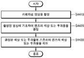
도 14는 일부 실시 예에 따라 렌즈에 대한 색상 정보를 획득하는 프로세스를 도시한 순서도이다.14 is a flowchart illustrating a process of obtaining color information for a lens, in accordance with some embodiments.
HMD 디바이스는 렌즈의 식별 정보를 획득할 수 있다(S1410). 여기서, 렌즈의 식별 정보는 HMD 디바이스가 렌즈를 식별하기 위한 정보를 의미한다. 예를 들어, 렌즈의 식별 정보는 렌즈의 종류에 따라 부여된 코드일 수 있다. HMD 디바이스가 렌즈의 식별 정보를 획득하는 방법은 실시 예에 따라서 다양하게 구현될 수 있다. 예를 들어, 렌즈에 금속 선이 구비된 경우, 금속 선이 배치된 위치 등을 이용하여 렌즈의 식별 정보를 획득할 수 있다. 다른 예를 들면, 렌즈의 표면에 코드(예를 들어, 바코드나 Quick Response Code)가 표시되어 있는 경우, HMD 디바이스는 렌즈 상에 표시된 코드로부터 렌즈의 식별 정보를 획득할 수 있다.The HMD device may obtain identification information of the lens (S1410). Here, the lens identification information means information for the HMD device to identify the lens. For example, the identification information of the lens may be a code assigned according to the type of the lens. A method for the HMD device to obtain lens identification information may be implemented in various ways according to embodiments. For example, when a metal line is provided on the lens, identification information of the lens may be obtained using a position where the metal line is disposed. As another example, when a code (eg, a barcode or a Quick Response Code) is marked on the surface of the lens, the HMD device may obtain identification information of the lens from the code displayed on the lens.
여기서, 획득되는 렌즈의 식별 정보는 렌즈의 색상에 따라서 부여된 정보일 수 있다. 예를 들면, 검은색 렌즈의 경우 식별 정보가 "01"이고, 투명한(무색) 렌즈의 경우 식별 정보가 "00"일 수 있다. 이 경우, HMD 디바이스는 획득된 식별 정보에 상응하는 렌즈에 대한 색상 정보를 획득할 수 있다(S1420).Here, the obtained lens identification information may be information given according to the color of the lens. For example, in the case of a black lens, the identification information may be “01”, and in the case of a transparent (colorless) lens, the identification information may be “00”. In this case, the HMD device may obtain color information about the lens corresponding to the obtained identification information (S1420).
이후, HMD 디바이스는 획득된 색상 정보에 기초하여 디스플레이될 영상을 수정할 수 있다(S1430). HMD 디바이스는 실시 예에 따라서 영상을 다양한 방법으로 수정할 수 있다. 예를 들어, HMD 디바이스는 영상 내에 포함된 텍스트가 렌즈의 색상의 보색으로 표시되도록 영상을 수정할 수 있다.Thereafter, the HMD device may modify the image to be displayed based on the obtained color information ( S1430 ). The HMD device may modify an image in various ways according to an embodiment. For example, the HMD device may modify the image so that text included in the image is displayed as a complementary color of the color of the lens.
다만, 본 발명의 실시 예가 HMD 디바이스가 영상의 색상을 수정하는 것으로만 한정되는 것은 아니다. 예를 들어 HMD 디바이스는 영상에 포함된 객체(예를 들어, 아이콘 등의 GUI 객체)의 크기를 확대 또는 축소시킬 수 있다. 또 다른 예를 들면, HMD 디바이스는 영상에 포함된 객체(예를 들어, 아이콘 등의 GUI 객체)의 형태를 변경할 수도 있다.However, the embodiment of the present invention is not limited only to the HMD device to correct the color of the image. For example, the HMD device may enlarge or reduce the size of an object (eg, a GUI object such as an icon) included in the image. As another example, the HMD device may change the shape of an object (eg, a GUI object such as an icon) included in the image.
이후, HMD 디바이스는 수정된 영상을 디스플레이할 수 있다(S1440).Thereafter, the HMD device may display the corrected image (S1440).
도 15는 일부 실시 예에 따라 금속선(metal line)을 이용하여 렌즈를 식별하기 위한 HMD 디바이스의 구조를 도시한 외형도이다.15 is an external view illustrating a structure of an HMD device for identifying a lens using a metal line, according to some embodiments.
일부 실시 예에 따른 HMD 디바이스(1500)는 프레임(1510)의 일 측에 위치한 디스플레이부(1511)와 전극(1532)을 구비할 수 있다. 일부 실시 예에 따른 HMD 디바이스(1500)는 렌즈(1520)를 탈부착할 수 있다. 여기서, 탈부착 가능한 렌즈(1520)는 금속선(metal lines, 1531)을 구비할 수 있다. 여기서, 전극(1532) 및 금속선(1531)은 렌즈(1520)가 프레임(1510)에 부착되면 서로 접촉될 수 있는 위치에 배치될 수 있다. 렌즈(1520)가 프레임(1510)에 부착되면, HMD 디바이스(1500)는 전극(1532)을 이용하여 금속선(1531)의 위치를 감지할 수 있다. HMD 디바이스(1500)는 감지된 전극(1531)의 위치에 기초하여 렌즈(1520)의 식별 정보를 획득할 수 있다. 일부 실시 예에 따르면, 프레임(1510)의 일 측에 자석(1540)을 구비함으로써 렌즈(1520)가 프레임(1510)에 고정될 수 있다.The
도 16은 일부 실시 예에 따른 금속선 및 전극의 구조를 포함하는 HMD 디바이스 및 렌즈의 일부를 도시한 도면이다.16 is a diagram illustrating a part of an HMD device and a lens including structures of metal wires and electrodes according to some embodiments.
일부 실시 예에 따르면, 탈부착 가능한 렌즈(1520)는 금속선(1531)을 구비할 수 있다. 여기서, 금속선(1531)은 렌즈(1520)의 종류에 따라서 할당되는 고유한 위치에 배치될 수 있다. 렌즈(1520)가 프레임(1510)에 부착되는 경우, 금속선(1531)이 전극(1532)에 접촉될 수 있다.According to some embodiments, the
금속선(1531)이 전극(1532)에 접촉되면, HMD 디바이스(1500)는 금속선(1531)이 배치된 위치를 인식할 수 있다. HMD 디바이스(1500)는 금속선(1531)이 배치된 위치에 상응하는 렌즈(1520)의 식별 정보를 획득할 수 있다.When the
도 17은 일부 실시 예에 따라 렌즈에 표시된 코드를 이용하여 렌즈를 식별하는 방법을 도시한 개념도이다.17 is a conceptual diagram illustrating a method of identifying a lens using a code displayed on the lens, according to some embodiments.
일부 실시 예에 따르면, HMD 디바이스(1700)는 렌즈(1720)에 구비된 코드(1721)를 이용하여 렌즈(1720)의 식별 정보를 획득할 수 있다. 도 17에서 코드(1721)가 렌즈(1720)의 전면부에 표시된 것으로 도시하였으나, 코드(1721)의 위치는 실시 예에 따라 변경될 수 있다.According to some embodiments, the
일부 실시 예에 따르면, 코드(1721)는 HMD 디바이스(1700)가 광학적으로 판독할 수 있도록 표시된 부호 등을 의미할 수 있다. 예를 들어, 코드(1721)는 QR 코드나 바코드 등일 수 있다. 이 경우, HMD 디바이스(1700)는 카메라(1710)를 이용하여 코드(1721)가 표시된 위치를 촬영하고, 촬영된 영상으로부터 렌즈(1720)의 식별 정보를 획득할 수 있따.According to some embodiments, the
도 18은 다른 일부 실시 예에 따라 감광 센서를 이용하여 렌즈의 색상 정보를 획득하는 프로세스를 도시한 순서도이다.18 is a flowchart illustrating a process of acquiring color information of a lens using a photosensitive sensor, according to another exemplary embodiment.
일부 실시 예에 따른 HMD 디바이스는 감광 센서를 구비할 수 있다. 감광 센서는 광과 같은 방사에너지에 응답함으로써 광을 검출할 수 있는 센서를 의미한다. HMD 디바이스는 감광 센서를 이용하여 렌즈를 투과한 빛을 검출하고, 분석할 수 있다(S1810).The HMD device according to some embodiments may include a photosensitive sensor. The photosensitive sensor refers to a sensor capable of detecting light by responding to radiant energy such as light. The HMD device may detect and analyze the light passing through the lens using the photosensitive sensor (S1810).
이후, HMD 디바이스는 분석 결과에 기초하여 렌즈에 대한 색상 정보를 결정할 수 있다(S1820). 예를 들어, HMD 디바이스는 감광 센서를 이용하여 검출된 광의 스펙트럼을 분석할 수 있다. 검출된 광에 청색광의 비율이 높은 경우, HMD 디바이스는 청색에 대응되는 색상 정보를 렌즈에 대한 색상 정보를 획득할 수 있다.Thereafter, the HMD device may determine color information about the lens based on the analysis result ( S1820 ). For example, the HMD device may analyze a spectrum of detected light using a photosensitive sensor. When the ratio of the detected light to the blue light is high, the HMD device may obtain color information corresponding to blue and color information about the lens.
렌즈에 대한 색상 정보가 획득되면, HMD 디바이스는 획득된 색상 정보에 기초하여 영상을 수정하고(S1830) 수정된 영상을 디스플레이할 수 있다(S1840).When the color information on the lens is obtained, the HMD device may correct the image based on the obtained color information (S1830) and display the corrected image (S1840).
도 19는 다른 일부 실시 예에 따라 감광 센서를 이용하여 렌즈에 대한 색상 정보를 획득하는 방법을 도시한 개념도이다.19 is a conceptual diagram illustrating a method of acquiring color information about a lens using a photosensitive sensor according to another exemplary embodiment.
일부 실시 예에 따른 HMD 디바이스는 렌즈(1920)를 기준으로 사용자의 반대편에 위치하는 광원(1910)으로부터 발생된 광을 수신할 수 있는 위치에 감광 센서(1930)를 구비할 수 있다. 예를 들어, 도 19를 참조하면, HMD 디바이스의 프레임의 일 측에 감광 센서(1930)가 배치될 수 있다. 일부 실시 예에 따른 HMD 디바이스는 렌즈(1920)를 투과한 빛을 분석한 결과로서, 렌즈에 대한 색상 정보를 획득할 수 있다.The HMD device according to some embodiments may include the
도 20은 또 다른 일부 실시 예에 따라 사용자의 동공의 크기에 기초하여 렌즈에 대한 색상 정보를 획득하는 프로세스를 도시한 순서도이다.20 is a flowchart illustrating a process of obtaining color information about a lens based on a size of a user's pupil according to another exemplary embodiment.
일부 실시 예에 따르면, HMD 디바이스는 카메라를 이용하여 영상을 촬영할 수 있다(S2010). 여기서, 촬영된 영상은 사용자의 안구가 촬영된 영상을 포함할 수 있다.According to some embodiments, the HMD device may capture an image using a camera (S2010). Here, the captured image may include an image of the user's eyeball.
HMD 디바이스는 촬영된 영상에 대한 영상 인식을 수행할 수 있다. HMD 디바이스는 영상 인식을 수행한 결과로서 영상에 포함된 동공의 크기 값을 획득할 수 있다. 획득된 동공의 크기 값에 기초하여, 영상에 포함된 동공의 크기 변화를 결정할 수 있다(S2020).The HMD device may perform image recognition on the captured image. The HMD device may acquire the value of the size of the pupil included in the image as a result of image recognition. Based on the obtained pupil size value, a change in the size of the pupil included in the image may be determined (S2020).
이후, HMD 디바이스는 동공의 크기 변화에 기초하여 렌즈에 대한 색상 정보를 결정할 수 있다(S2030). 렌즈의 투과율이 높은 경우, 사용자의 눈에 많은 광이 입사됨에 따라서 사용자의 동공의 크기가 축소될 수 있다. 반대로, 렌즈의 투과율이 낮은 경우, 사용자의 눈에 적은 광이 입사되므로 사용자의 동공의 크기가 확대될 수 있다. 이러한 원리에 기초하여, HMD 디바이스는 사용자의 동공의 크기에 기초하여 렌즈에 대한 색상 정보를 획득할 수 있다. 즉, 사용자의 동공의 크기가 큰 경우 HMD 디바이스는 렌즈의 색상이 밝은 색상인 것으로 판단할 수 있다. 반대로, 사용자의 동공의 크기가 작은 경우 HMD 디바이스는 렌즈의 색상이 어두운 색상인 것으로 판단할 수 있다.Thereafter, the HMD device may determine color information about the lens based on the change in the size of the pupil ( S2030 ). When the transmittance of the lens is high, the size of the user's pupil may be reduced as a lot of light is incident on the user's eye. Conversely, when the transmittance of the lens is low, since less light is incident on the user's eye, the size of the user's pupil may be enlarged. Based on this principle, the HMD device may acquire color information about the lens based on the size of the user's pupil. That is, when the size of the user's pupil is large, the HMD device may determine that the color of the lens is a bright color. Conversely, when the size of the user's pupil is small, the HMD device may determine that the color of the lens is dark.
렌즈에 대한 색상 정보가 획득되면, HMD 디바이스는 획득된 색상 정보에 기초하여 영상을 수정하고(S20400) 수정된 영상을 디스플레이할 수 있다(S2050).When color information about the lens is obtained, the HMD device may correct the image based on the obtained color information (S20400) and display the corrected image (S2050).
도 21은 또 다른 일부 실시 예에 따라 사용자의 동공의 크기에 기초하여 색상 정보를 획득하는 방법을 도시한 개념도이다.21 is a conceptual diagram illustrating a method of acquiring color information based on a size of a user's pupil according to another exemplary embodiment.
도 21을 참조하면, HMD 디바이스(2100)는 HMD 디바이스(2100)의 일 측에 구비된 카메라(2110)를 이용하여 사용자의 안구(2120)를 촬영할 수 있다. 도 21에서는 카메라와 사용자 사이에 렌즈가 배치되는 것으로 도시되었으나, 카메라의 위치는 실시 예에 따라서 다양하게 변화될 수 있다. HMD 디바이스(2100)는 사용자의 안구(2120)를 촬영한 영상으로부터 동공의 크기를 검출할 수 있다. HMD 디바이스(2100)는 검출된 동공의 크기에 기초하여 렌즈의 색상 정보를 획득할 수 있다.Referring to FIG. 21 , the
도 22는 또 다른 일부 실시 예에 따라 사용자의 설정에 기초하여 렌즈에 대한 색상 정보를 획득하는 방법을 도시한 개념도이다.22 is a conceptual diagram illustrating a method of acquiring color information about a lens based on a user's setting according to another exemplary embodiment.
일부 실시 예에 따르면, 사용자는 렌즈(2220)의 색상 정보를 직접 설정할 수 있다. 도 22를 참조하면, HMD 디바이스(2200)는 렌즈(2220)의 색상 정보를 설정하기 위한 사용자 인터페이스(2210)를 표시할 수 있다. 사용자 인터페이스(2210)는, 예를 들어, 색상 정보의 목록을 포함할 수 있다.According to some embodiments, the user may directly set color information of the
HMD 디바이스는 사용자로부터 입/출력부를 통해서 렌즈의 색상 정보(2220) 중 어느 하나를 선택하는 입력을 수신할 수 있다. 예를 들어, 도 22를 참조하면, 사용자 인터페이스(2210)를 통해서 갈색(2211)이 선택된 경우, HMD 디바이스는 렌즈에 대한 색상 정보로 갈색에 대응되는 RGB 값을 획득할 수 있다.The HMD device may receive an input for selecting any one of the
도 23은 또 다른 일부 실시 예에 따라 HMD 디바이스가 영상을 디스플레이하는 프로세스를 도시한 순서도이다. 또한, 도 24는 또 다른 일부 실시 예에 따라 HMD 디바이스가 영상을 디스플레이하는 방법을 도시한 개념도이다.23 is a flowchart illustrating a process of displaying an image by an HMD device according to another exemplary embodiment. Also, FIG. 24 is a conceptual diagram illustrating a method of displaying an image by an HMD device according to another exemplary embodiment.
일부 실시 예에 따르면, HMD 디바이스는 영상 처리를 수행할 능력이 없는 피동장치(passive device)일 수 있다. 이 경우, HMD 디바이스는 HMD 디바이스와 통신 가능한 능동장치(active device)를 이용하여 영상을 수정할 수 있다. According to some embodiments, the HMD device may be a passive device incapable of performing image processing. In this case, the HMD device may modify the image using an active device capable of communicating with the HMD device.
도 23 및 도 24를 참조하면, 먼저 HMD 디바이스(2300)는 렌즈의 식별 정보를 획득할 수 있다(S2310). 이후, HMD 디바이스(2300)는 획득된 렌즈의 식별 정보를 능동장치인 제어 단말기(2400)로 전송할 수 있다.23 and 24 , first, the
이후, 제어 단말기(2400)는 HMD 디바이스(2300)로부터 수신된 식별 정보에 기초하여 HMD 디바이스(2300)에 디스플레이될 영상을 보정하거나 생성할 수 있다(S2330).Thereafter, the
도 25는 일부 실시 예에 따라 HMD 디바이스가 렌즈를 추천하는 프로세스를 도시한 순서도이다.25 is a flowchart illustrating a process for an HMD device to recommend a lens, in accordance with some embodiments.
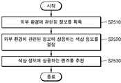
먼저, HMD 디바이스는 외부 환경에 관련된 정보를 획득할 수 있다(S2510). 외부 환경에 관련된 정보는 적어도 하나의 센서를 통해 감지된 HMD 디바이스 주변의 상태를 나타내는 정보일 수 있다. 예를 들어, 외부 환경에 관련된 정보는 HMD 디바이스 주변의 조도에 대한 정보, HMD 디바이스의 위치에 대한 GPS(Global Positioning System) 좌표 값 또는 HMD 디바이스에서 감지된 소리에 대한 정보를 포함할 수 있다.First, the HMD device may acquire information related to the external environment (S2510). The information related to the external environment may be information indicating a state around the HMD device sensed through at least one sensor. For example, the information related to the external environment may include information about illuminance around the HMD device, a Global Positioning System (GPS) coordinate value for the location of the HMD device, or information about a sound detected by the HMD device.
이후, HMD 디바이스는 S2510 단계에서 획득된 외부 환경에 관련된 정보에 상응하는 외부 환경의 색상 정보를 결정할 수 있다(S2520). 일부 실시 예에 따르면, 외부 환경의 색상 정보는 HMD 디바이스 주변의 조도에 대한 정보와 같은 외부 환경에 관련된 정보 자체일 수 있다. 예를 들어, HMD 디바이스는 카메라(560)를 이용하여 HMD 디바이스의 외부를 촬영할 수 있다. HMD 디바이스는 촬영된 영상으로부터 외부 환경에 관련된 정보를 획득할 수 있다. 이 경우 S2520 단계는 생략될 수 있다. 또는, 다른 일부 실시 예에 따르면, 외부 환경의 색상 정보는 HMD 디바이스 주변의 조도에 대한 정보, HMD 디바이스의 위치에 대한 GPS(Global Positioning System) 좌표 값 또는 HMD 디바이스에서 감지된 소리에 대한 정보에 기초하여 HMD 디바이스 내부 또는 외부에 구비되는(도시되지 않음) 색상 DB에 포함된 색상 정보로부터 선택된 색상 코드일 수 있다. HMD 디바이스는 결정된 외부 환경의 색상 정보에 상응하는 렌즈를 추천할 수 있다(S2530). "렌즈를 추천한다"는 것은, 예를 들어, HMD 디바이스가 렌즈를 교체하라는 메시지를 디스플레이하는 것을 의미할 수 있다. 예를 들어 S2510 단계에서 획득된 조도가 낮은 값인 경우, HMD 디바이스는 무색 렌즈를 추천할 수 있다. 반대로, S2510 단계에서 획득된 조도 가 높은 값인 경우, HMD 디바이스는 갈색, 청색, 검은색 등과 같은 유색 렌즈를 추천할 수 있다.Thereafter, the HMD device may determine color information of the external environment corresponding to the information related to the external environment obtained in step S2510 ( S2520 ). According to some embodiments, the color information of the external environment may be information related to the external environment itself, such as information about the illuminance around the HMD device. For example, the HMD device may photograph the outside of the HMD device using the
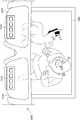
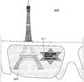
도 27은 HMD 디바이스(2700)가 렌즈를 추천하는 방법을 도시한 예시도이다. 도 27을 참조하면, HMD 디바이스(2700)는 외부 환경에 관련된 정보에 기초하여 선택된 렌즈를 추천하는 메시지(2710)를 디스플레이할 수 있다. 여기서, HMD 디바이스(2700)는 사용자가 렌즈(2720) 상에 메시지(2710)가 표시된 것으로 인식할 수 있도록 메시지(2710)를 디스플레이할 수 있다.27 is an exemplary diagram illustrating a method for the
일부 실시 예에 따라서, HMD 디바이스가 렌즈(2720)의 색상 내지 투과율을 제어할 수 있는 경우, S2530 단계는 S2520 단계에서 결정된 외부 환경의 색상 정보에 기초하여 HMD 디바이스가 렌즈(2720)의 색상 내지 투과율을 제어하는 단계로 대체될 수도 있다.According to some embodiments, when the HMD device can control the color or transmittance of the
도 26은 다른 일부 실시 예에 따라 HMD 디바이스가 렌즈를 추천하는 프로세스를 도시한 순서도이다. 또한, 도 28 내지 도 31은 일부 실시 예에 따라 HMD 디바이스가 렌즈를 추천하는 방법을 도시한 예시도이다.26 is a flowchart illustrating a process of recommending a lens by an HMD device according to some other exemplary embodiments. 28 to 31 are exemplary views illustrating a method of recommending a lens by an HMD device according to some embodiments.
HMD 디바이스는 디스플레이부를 통해 출력될 수 있는 컨텐트를 선택할 수 있다(S2610). 예를 들어, HMD 디바이스는 컨텐츠 목록을 표시하고, HMD 디바이스의 입출력부를 통해 수신된 사용자 입력에 따라서 컨텐츠 목록 중에서 컨텐트를 선택할 수 있다. 여기서, 컨텐츠 목록은 실행 가능한 애플리케이션이나 사진이나 동영상 등의 멀티미디어 컨텐트 등을 포함할 수 있다.The HMD device may select content that can be output through the display unit (S2610). For example, the HMD device may display a content list and select content from the content list according to a user input received through an input/output unit of the HMD device. Here, the content list may include executable applications or multimedia content such as pictures or videos.
예를 들어, 도 28을 참조하면, HMD 디바이스(2700)는 렌즈(2720) 상에 컨텐츠 목록(2810)을 표시할 수 있다. HMD 디바이스(2700)는 컨텐츠 목록(2810)에 포함된 컨텐츠 중 어느 하나를 선택할 수 있다. 도 28에 도시된 바와 같이, HMD 디바이스(2700)는 컨텐츠 목록(2810) 중에서 웹 브라우저(2811)를 선택할 수 있다.For example, referring to FIG. 28 , the
이후, HMD 디바이스는 S2610 단계에서 선택된 컨텐트에 상응하는 렌즈를 추천할 수 있다(S2620). 예를 들어, 도 29를 참조하면, HMD 디바이스(2700)는 웹 브라우저(2811)가 선택된 경우 웹 브라우저(2811) 이용 시 적합한 색상을 가지는 렌즈를 추천하는 메시지(2920)를 렌즈(2820) 상에 디스플레이할 수 있다. 또한, HMD 디바이스(2700)는 웹 브라우저 실행 화면(2910)을 디스플레이할 수 있다.Thereafter, the HMD device may recommend a lens corresponding to the content selected in step S2610 ( S2620 ). For example, referring to FIG. 29 , when the
이후, 추천된 렌즈가 HMD 디바이스에 결합되었는지 판단할 수 있다(S2630). S2630 단계에서, HMD 디바이스는 다양한 방법으로 추천된 렌즈가 HMD 디바이스에 결합되었는지 여부를 판단할 수 있다. 예를 들어, HMD 디바이스는 렌즈의 식별정보를 획득하고, 획득된 식별정보가 추천된 렌즈의 식별정보와 일치하는지 여부를 판단할 수 있다. 다른 예를 들면, HMD 디바이스는 렌즈의 색상 정보를 획득하고, 획득된 렌즈의 색상 정보와 추천된 렌즈의 색상 정보가 일치하는지 여부를 판단할 수 있다. 도 30에 도시된 바와 같이, 렌즈(2820)가 다른 색상을 가지는 렌즈(2821)로 교체되는 경우, HMD 디바이스는 추천된 렌즈가 HMD 디바이스에 결합되었는지 여부를 판단할 수 있다. 추천된 렌즈가 HMD 디바이스에 결합되지 않은 경우, HMD 디바이스는 S2620 단계를 다시 수행할 수 있다.Thereafter, it may be determined whether the recommended lens is coupled to the HMD device (S2630). In operation S2630, the HMD device may determine whether the recommended lens is coupled to the HMD device in various ways. For example, the HMD device may obtain identification information of a lens, and determine whether the obtained identification information matches identification information of a recommended lens. As another example, the HMD device may obtain color information of a lens and determine whether the obtained color information of a lens and color information of a recommended lens match. 30 , when the
일부 실시 예에 따라서, HMD 디바이스가 렌즈(2820)의 색상 내지 투과율을 제어할 수 있는 경우, S2620 단계 및 S2630 단계는 HMD 디바이스(2820)가 렌즈(2820)의 투과율 내지 색상을 선택된 컨텐트에 따라 추천되는 투과율 내지 색상으로 변화되도록 렌즈(2820)를 제어하는 단계로 대체될 수도 있다.According to some embodiments, when the HMD device can control the color or transmittance of the
이후, HMD 디바이스는 선택된 컨텐트를 렌즈 상에 디스플레이할 수 있다(S2640). S2640 단계에서 디스플레이되는 컨텐트는 S2620 단계 및 S2630 단계에서 변경된 렌즈의 색상 정보에 기초하여 수정된 영상일 수 있다. 도 31에 도시된 바와 같이, HMD 디바이스(2700)는 색상이 변경된 렌즈(2821) 상에 색상이 수정된 웹 브라우저 실행 화면(2911)을 디스플레이 할 수 있다.Thereafter, the HMD device may display the selected content on the lens (S2640). The content displayed in step S2640 may be an image corrected based on the color information of the lens changed in steps S2620 and S2630. 31 , the
도 32는 일부 실시 예에 따라 렌즈의 색상 또는 투과율을 변경할 수 있는 HMD 디바이스가 영상을 디스플레이하는 프로세스를 도시한 순서도이다.32 is a flowchart illustrating a process of displaying an image by an HMD device capable of changing a color or transmittance of a lens, according to some embodiments.
일부 실시 예에 따른 HMD 디바이스는 렌즈의 색상 내지 투과율을 제어할 수 있다(S3110). 예를 들어, HMD 디바이스는 조도 센서를 이용하여 조도를 측정하고, 측정된 조도에 기초하여 렌즈의 투과율을 제어할 수 있다. 다만, 이에 한정되지 아니한다. 다른 예를 들면, HMD 디바이스는 주변 환경을 카메라를 이용하여 촬영하고, 촬영된 영상에 기초하여 조도를 측정할 수 있다. 또는 HMD 디바이스의 위치를 나타내는 정보를 이용하여 HMD 디바이스 주변의 조도를 측정할 수도 있다. 측정된 조도가 낮은 경우, 렌즈의 투과율을 증가시킬 수 있다. 반대로 측정된 조도가 높은 경우, 사용자의 눈을 보호하기 위해 렌즈의 투과율을 감소시킬 수 있다.The HMD device according to some embodiments may control the color or transmittance of the lens (S3110). For example, the HMD device may measure illuminance using an illuminance sensor and control transmittance of a lens based on the measured illuminance. However, the present invention is not limited thereto. As another example, the HMD device may photograph a surrounding environment using a camera and measure illuminance based on the captured image. Alternatively, the illuminance around the HMD device may be measured using information indicating the location of the HMD device. When the measured illuminance is low, the transmittance of the lens may be increased. Conversely, when the measured illuminance is high, the transmittance of the lens may be reduced to protect the user's eyes.
렌즈가 전기 변색 글래스, LC(Liquid Crystal) 패널 또는 SPD(Suspended Particle Device) 등으로 구성됨으로써 HMD 디바이스가 렌즈의 색상 내지 투과율을 제어할 수 있다. 예를 들어, 렌즈는 OCA(Optically Clear Adhesive)를 이용하여 접합된 EC(Electrochromic Material) 박막 투명 전극과 ITO(Induim-Tin Oxide), 및 두 ITO 글래스/필름 사이에 채워진 전해질로 구성된 전기 변색 글래스를 포함할 수 있다. 렌즈가 전기 변색 글래스인 경우, HMD 디바이스는 전기 변색 글래스에 인가되는 전압의 크기를 조절함으로써 렌즈의 색상 내지 투과율을 제어할 수 있다.Since the lens is formed of electrochromic glass, a liquid crystal (LC) panel, or a suspended particle device (SPD), the HMD device may control the color or transmittance of the lens. For example, the lens is made of an electrochromic material (EC) thin film transparent electrode bonded using OCA (Optically Clear Adhesive), an induim-tin oxide (ITO), and an electrochromic glass composed of an electrolyte filled between the two ITO glasses/films. may include When the lens is electrochromic glass, the HMD device may control the color or transmittance of the lens by adjusting the magnitude of a voltage applied to the electrochromic glass.
이후, HMD 디바이스는 렌즈의 색상 또는 투과율에 기초하여 영상을 수정할 수 있다(S3120). HMD 디바이스는 S3120 단계에서 수정된 영상을 디스플레이할 수 있다. 예를 들어, HMD 디바이스가 렌즈의 색상이 청색이 되도록 렌즈를 제어한 경우, HMD 디바이스는 청색의 보색인 붉은색으로 텍스트가 디스플레이되도록 할 수 있다.Thereafter, the HMD device may modify the image based on the color or transmittance of the lens ( S3120 ). The HMD device may display the corrected image in step S3120 . For example, when the HMD device controls the lens so that the color of the lens becomes blue, the HMD device may display text in red, which is a complementary color of blue.
도 33은 일부 실시 예에 따라 영상을 수정하기 위해 이용될 수 있는 보색표를 도시한 예시도이다.33 is an exemplary diagram illustrating a complementary color table that may be used to correct an image according to some embodiments.
일부 실시 예에 따른 HMD 디바이스는 보색표를 이용하여 영상을 수정할 수 있다. 예를 들어, 도 12의 S1210 단계에서 획득된 색상 정보가 FFFF00(노랑)인 경우, HMD 디바이스는 노랑색의 보색이 되는 남색으로 텍스트를 디스플레이할 수 있다. 다만, 이에 한정되는 것은 아니며, 영상을 수정하는 방법은 실시 예에 따라서 달라질 수 있다.The HMD device according to some embodiments may modify an image using a complementary color table. For example, when the color information obtained in step S1210 of FIG. 12 is FFFF00 (yellow), the HMD device may display the text in navy blue that is a complementary color of yellow. However, the present invention is not limited thereto, and a method of correcting an image may vary according to an embodiment.
여기서, 색상 정보는 실시 예에 따라 변형될 수 있다. 예를 들어, 일부 실시 예에 따르면 색상 정보는 렌즈 자체의 색상을 지시하는 정보일 수도 있다. 또는 다른 일부 실시 예에 따르면 색상 정보는 사용자에게 HMD 디바이스에 의해 디스플레이된 영상 주변의 배경의 색상으로 인식되는 색상을 지시할 수 있다. 이 경우, HMD 디바이스에 구비된 감광 센서를 이용하여 렌즈를 투과한 광의 색상을 검출함으로써, HMD 디바이스는 배경의 색상으로 인식되는 색상을 지시하는 색상 정보를 획득할 수 있다. 또 다른 일부 실시 예에 따르면, 색상 정보는 외부 환경 정보에 기초하여 결정된 정보일 수도 있다.Here, the color information may be modified according to an embodiment. For example, according to some embodiments, the color information may be information indicating the color of the lens itself. Alternatively, according to some other exemplary embodiments, the color information may indicate a color recognized as a background color around an image displayed by the HMD device to the user. In this case, by detecting the color of the light passing through the lens using a photosensitive sensor provided in the HMD device, the HMD device may obtain color information indicating a color recognized as a color of the background. According to another exemplary embodiment, the color information may be information determined based on external environment information.
도 34 및 도 35는 일부 실시 예에 따라 HMD 디바이스가 보정된 영상을 디스플레이하는 예시를 도시한 개념도이다.34 and 35 are conceptual diagrams illustrating an example in which an HMD device displays a corrected image according to some embodiments.
도 34는 HMD 디바이스(3300)를 착용한 사용자가 실내 풍경(3301)을 볼 때 영상(3310)을 디스플레이하는 예시를 도시한 도면이다. HMD 디바이스(3300)는 조도를 측정할 수 있다. HMD 디바이스(3300)가 실내에 위치함에 따라서 측정되는 조도가 낮은 경우, HMD 디바이스(3300)는 렌즈(3320)의 투과율을 높이거나, 렌즈(3320)에 색상이 나타나지 않도록 할 수 있다. HMD 디바이스(3300)의 사용자는 렌즈(3320) 상에 영상(3310)이 표시되는 것으로 인식할 수 있다.34 is a diagram illustrating an example of displaying an
도 35는 HMD 디바이스(3300)를 착용한 사용자가 실외 풍경(3401)을 볼 때 영상(3311)을 디스플레이하는 예시를 도시한 도면이다. 측정되는 조도가 높아짐에 따라서 HMD 디바이스(3300)는 렌즈(3321)의 투과율 내지 렌즈(3321)의 색상을 제어할 수 있다. 렌즈(3321)의 투과율 내지 색상이 변경되면, HMD 디바이스(3300)는 변경된 렌즈(3321)의 투과율 내지 색상에 대응되는 색상 정보에 기초하여 영상(3310)을 수정할 수 있다. 도 35에 도시된 바와 같이, HMD 디바이스(3300)는 색상이나 아이콘의 크기 등이 수정된 영상(3311)을 디스플레이할 수 있다.35 is a diagram illustrating an example of displaying an
도 36 및 도 37은 다른 일부 실시 예에 따라 HMD 디바이스가 보정된 영상을 디스플레이하는 예시를 도시한 개념도이다.36 and 37 are conceptual diagrams illustrating an example in which an HMD device displays a corrected image according to another exemplary embodiment.
도 36에 도시된 바와 같이, HMD 디바이스(3500)는 증강 현실(Augmented Reality) 기능을 제공하기 위한 영상(3510)을 렌즈(3520) 상에 디스플레이할 수 있다. 증강 현실 기능을 제공하기 위한 영상(3510)은, 예를 들어, 사용자가 바라보고 있는 실제 물체에 대한 관련 정보일 수 있다. 도 37에 도시된 바와 같이 렌즈(3520)의 색상 내지 투과율이 변경된 경우, HMD 디바이스(3500)는 수정된 영상(3511)을 디스플레이할 수 있다. 수정된 영상(3511)은 색상뿐만 아니라 도 37에 도시된 바와 같이 영상에 포함된 객체의 형태 등이 변경된 영상일 수 있다.As shown in FIG. 36 , the
도 38은 일부 실시 예에 따른 HMD 디바이스의 구조를 간단히 도시한 블록도이다.38 is a block diagram simply illustrating a structure of an HMD device according to some embodiments.
HMD 디바이스는 색상 정보 획득부(3710), 제어부(3720) 및 디스플레이부(3730)를 포함할 수 있다.The HMD device may include a color
일부 실시 예에 따른 색상 정보 획득부(3710)는 렌즈의 색상 정보를 획득할 수 있다. 색상 정보 획득부(3710)는 실시 예에 따라 다양하게 구현될 수 있다. 예를 들어, 색상 정보 획득부(4710)는 도 15에 도시된 바와 같이 전극(1532)을 포함할 수 있다. 또는 색상 정보 획득부(4710)는 도 17에 도시된 바와 같이 카메라(1710) 등을 이용하여 코드를 인식하는 인식부를 포함하거나, 도 19에 도시된 바와 같이 감광 센서(1930)를 이용하여 렌즈의 색상 정보를 획득할 수도 있다. 또는, 제어부(3720)가 렌즈의 투과율 내지 색상 정보를 제어하는 경우, 색상 정보 획득부(3710)는 제어부(3720)에 포함될 수도 있다.The color
또한, 렌즈가 HMD 디바이스에 착탈 가능한 경우, 색상 정보 획득부(3710)는 HMD 디바이스에 렌즈가 결합되었는지 여부를 인식할 수 있다. 색상 정보 획득부(3710)는 HMD 디바이스에 결합된 렌즈가 인식되면, 결합된 렌즈에 대한 색상 정보를 획득할 수 있다.Also, when the lens is detachable from the HMD device, the color
제어부(3720)는 정보를 처리하고 HMD 디바이스의 각 부를 제어할 수 있다. 제어부(3720)는 색상 정보 획득부(3710)에 의해 획득된 색상 정보에 기초하여 영상을 수정할 수 있다. 제어부(3720)는 수정된 영상을 디스플레이하도록 디스플레이부(3730)를 제어할 수 있다.The
일부 실시 예에 따르면, 제어부(3720)는 렌즈의 색상 또는 투과율 중 적어도 하나를 제어할 수 있다. 이 경우, 렌즈는 전기 변색(Electrochoromic) 글래스, SPD(Suspended Particle Device), 또는 LC(Liquid Crystal)을 포함할 수 있다. 예를 들어, 렌즈는 도 10에 도시된 바와 같은 구조를 가지는 글래스를 포함할 수 있다. 제어부(3720)가 렌즈의 색상 또는 투과율을 제어하는 경우, 제어부(3720)는 변경된 렌즈의 색상 또는 제어율에 상응하는 렌즈의 색상 정보를 획득할 수 있다. 또한, 제어부(3720)는 획득된 렌즈의 색상 정보에 기초하여 영상을 수정할 수 있다.According to some embodiments, the
다른 일부 실시 예에 따르면, 제어부(3720)는 디스플레이부(3730)를 통해 출력 가능한 컨텐트를 선택할 수 있다. 예를 들어, HMD 디바이스는 컨텐츠 목록을 표시하고, HMD 디바이스의 입출력부를 통해 수신된 사용자 입력에 따라서 컨텐츠 목록 중에서 컨텐트를 선택할 수 있다. 여기서, 컨텐츠 목록은 실행 가능한 애플리케이션이나 사진이나 동영상 등의 멀티미디어 컨텐트 등을 포함할 수 있다.According to some other exemplary embodiments, the
또한, 다른 일부 실시 예에 따른 HMD 디바이스는 외부 조도에 대한 정보를 획득하는 조도 센서(미도시)를 더 포함할 수 있다. 제어부(3720)는 조도 센서를 이용하여 획득된 외부 조도에 대한 정보를 더 고려하여 영상을 수정할 수 있다. 예를 들어, 제어부(3720)는 외부 조도가 높을수록 영상의 밝기를 증가시킬 수 있다.Also, the HMD device according to some other exemplary embodiments may further include an illuminance sensor (not shown) configured to obtain information on external illuminance. The
일부 실시 예에 따른 HMD 디바이스는 사용자가 바라보는 풍경(영상의 배경)의 색상을 더 고려하여 영상을 수정할 수 있다. 도 39는 일부 실시 예에 따라 HMD 디바이스(4000)가 영상을 디스플레이하는 예시적인 프로세스를 도시한 순서도이다. 또한, 도 40 내지 43은 다른 일부 실시 예에 따라 HMD 디바이스(4000)가 보정된 영상(4125)을 디스플레이하는 예시를 도시한 개념도이다.The HMD device according to some embodiments may modify the image by further considering the color of the landscape (the background of the image) viewed by the user. 39 is a flowchart illustrating an exemplary process for the
먼저, HMD 디바이스(4000)는 배경 영상(4020)을 촬영할 수 있다(S3810). 본 실시 예에 따른 HMD 디바이스(4000)는 사용자(1)의 시선 방향의 영상을 촬영할 수 있는 카메라(4010)를 구비할 수 있다. HMD 디바이스(4000)는 카메라(4010)를 이용하여 배경 영상을 촬영할 수 있다.First, the
도 40을 참조하면, HMD 디바이스(4000)는 일 측에 카메라(4010)를 구비할 수 있다. HMD 디바이스(4000)를 착용한 사용자(1)가 횡단보도를 바라보고 있는 경우, 카메라(4010)는 횡단보도를 촬영한 배경 영상(4020)을 획득할 수 있다.Referring to FIG. 40 , the
이후, HMD 디바이스(4000)는 촬영된 배경 영상(4020) 내에서 HMD 디바이스(4000)가 디스플레이할 영상(4110)의 위치와 관련된 영상 표시 영역(4120)을 결정할 수 있다(S3920). HMD 디바이스(4000)가 영상(4110)을 표시할 때, 영상 표시 영역(4120)은 사용자(1)가 배경 영상(4020) 상에 영상(4110)이 표시되는 것으로 인지하는 위치를 포함하는 영역을 의미할 수 있다. 일부 실시 예에 따르면, 영상 표시 영역(4120)은 영상(4110)이 표시되는 위치에 따라서 결정될 수 있다.Thereafter, the
도 41을 참조하면, 영상(4110)이 HMD 디바이스(4000)의 좌측 상단에 디스플레이되는 경우, HMD 디바이스는 배경 영상(4020)의 좌측 상단에 영상 표시 영역(4120)이 위치하는 것으로 결정할 수 있다. 도 42를 참조하면, 사용자(1)는 배경 영상(4020) 내의 영상 표시 영역(4120) 상에 영상(4110)이 디스플레이된 것으로 인식할 수 있다. 여기서, 영상 표시 영역(4120) 내의 배경의 색상과 영상(4110)의 색상이 유사한 경우, 영상(4110)이 사용자에게 인식되기 어렵다. 따라서, 영상(4110)의 색상을 수정할 필요가 있다.Referring to FIG. 41 , when the
S3920 단계에서 영상 표시 영역(4120)이 결정되면, HMD 디바이스(4000)는 영상 표시 영역(4120)의 색상 정보를 결정할 수 있다(S3930). 여기서 S3930 단계는 실시 예에 따라 다양하게 구현될 수 있다. 예를 들어, HMD 디바이스(4000)는 영상 표시 영역(4120) 내에 포함된 픽셀들의 평균 색상(average hue)을 영상 표시 영역(4120)의 색상 정보로 결정할 수 있다. 또 다른 예를 들면, HMD 디바이스(4000)는 영상 표시 영역(4120) 내의 중심점과 같은 특징점으로부터 색상 정보를 추출할 수도 있다.When the
또한, 다른 일부 실시 예에 따르면, HMD 디바이스(4000)는 렌즈의 색상 및 영상 표시 영역(4120)의 색상을 함께 고려하여 색상 정보를 결정할 수 있다. 사용자(1)가 렌즈를 투과하여 물체를 보는 경우, 사용자(1)는 실제 물체의 색상과 다른 색상으로 물체를 인식할 수 있다. 따라서, HMD 디바이스(4000)는 S3930 단계에서 사용자(1)가 렌즈를 통해서 인식하는 물체의 색상을 영상 표시 영역(4120)의 색상 정보로 결정할 수 있다.Also, according to some other exemplary embodiments, the
이후, HMD 디바이스(4000)는 S3930 단계에서 결정된 영상 표시 영역(4120)의 색상 정보에 기초하여 영상을 수정할 수 있다(S3940). HMD 디바이스(4000)는 디스플레이부를 통해서 수정된 영상을 디스플레이할 수 있다(S3940).Thereafter, the
예를 들어, HMD 디바이스(4000)는 표시 영역(4120)의 색상 정보에 대한 보색을 결정하고, 영상(4110)의 색상을 결정된 보색으로 수정할 수 있다. 도 43을 참조하면, HMD 디바이스(4000)는 수정된 영상(4125)을 디스플레이함으로써, 영상(4124)이 배경(4020)으로부터 용이하게 구별될 수 있도록 할 수 있다.For example, the
S3940 단계에서 영상의 전부가 수정되어야 하는 것은 아니며, 영상의 테두리의 색상이 변화되거나, 영상 주변에 별도의 배경이 추가될 수도 있다.In step S3940, not all of the image needs to be corrected, and the color of the edge of the image may be changed or a separate background may be added around the image.
도 44는 일부 실시 예에 따라 HMD 디바이스가 렌즈의 색상 또는 투과율을 제어하는 프로세스를 도시한 순서도이다.44 is a flowchart illustrating a process by which an HMD device controls a color or transmittance of a lens, in accordance with some embodiments.
먼저, S4410 단계에서 HMD 디바이스는 HMD 디바이스에 구비된 카메라로 영상을 촬영할 수 있다(S4410). 여기서, 카메라는 HMD 디바이스의 외부를 향하여 배치될 수 있다. 즉, 카메라는 렌즈를 투과하지 않은 광을 수신함으로써 영상을 촬영할 수 있다.First, in step S4410, the HMD device may take an image with a camera provided in the HMD device (S4410). Here, the camera may be disposed toward the outside of the HMD device. That is, the camera may capture an image by receiving light that does not pass through the lens.
이후, S4420 단계에서 HMD 디바이스는 촬영된 영상에 기초하여 렌즈의 색상 또는 투과율을 결정할 수 있다. 여기서, 렌즈는 HMD 디바이스의 제어에 따라서 색상 또는 투과율을 변경할 수 있는 스마트 윈도우(smart window)를 포함할 수 있다. 예를 들어, HMD 디바이스는 촬영된 영상에 기초하여 외부 조도를 결정할 수 있다. 즉, HMD 디바이스는 촬영된 영상의 밝기를 분석하고, 분석 결과에 따라서 HMD 디바이스 외부의 조도를 결정할 수 있다. HMD 디바이스는 외부 조도가 높은 경우 렌즈의 색상을 갈색과 같은 어두운 색상으로 결정할 수 있다. 반대로, HMD 디바이스는 외부 조도가 낮은 경우 렌즈가 색상을 가지지 않도록 하거나 투과율이 높도록 렌즈의 색상 또는 투과율을 결정할 수 있다.Thereafter, in step S4420, the HMD device may determine the color or transmittance of the lens based on the captured image. Here, the lens may include a smart window capable of changing a color or transmittance according to the control of the HMD device. For example, the HMD device may determine the external illuminance based on the captured image. That is, the HMD device may analyze the brightness of the captured image, and determine the external illuminance of the HMD device according to the analysis result. The HMD device may determine the color of the lens to be a dark color such as brown when external illumination is high. Conversely, the HMD device may determine the color or transmittance of the lens so that the lens does not have a color or has a high transmittance when external illumination is low.
이후, S4430 단계에서 HMD 디바이스는 렌즈가 S4420 단계에서 결정된 색상 또는 투과율을 가지도록 렌즈의 색상 또는 투과율을 제어할 수 있다.Thereafter, in step S4430, the HMD device may control the color or transmittance of the lens so that the lens has the color or transmittance determined in step S4420.
도 45는 다른 일부 실시 예에 따라 HMD 디바이스가 색상 또는 투과율을 제어하기 위해 영상을 촬영하는 방법을 도시한 개념도이다.45 is a conceptual diagram illustrating a method of capturing an image by an HMD device to control color or transmittance according to another exemplary embodiment.
다른 일부 실시 예에 따르면, HMD 디바이스는 복수의 카메라를 구비할 수 있다. 도 45를 참조하면, HMD 디바이스는 제 1 카메라(560-1) 및 제 2 카메라(560-2)를 구비할 수 있다. 제 1 카메라(560-1)는 HMD 디바이스 외부에서 렌즈(580)을 투과하지 않은 광(4520)을 수신하도록 배치될 수 있다. 제 2 카메라(560-2)는 렌즈(580)를 투과한 광(4510)을 수신하도록 배치될 수 있다.According to some other embodiments, the HMD device may include a plurality of cameras. Referring to FIG. 45 , the HMD device may include a first camera 560-1 and a second camera 560-2. The first camera 560-1 may be arranged to receive the light 4520 that does not pass through the
HMD 디바이스는 제 1 카메라(560-1)를 통해서 수신된 광(4520) 및 제 2 카메라(560-2)를 통해 수신된 광(2510)에 기초하여 렌즈의 색상 또는 투과율을 결정할 수 있다. 예를 들어, HMD 디바이스는 제 1 카메라(560-1)를 통해서 수신된 광(4520)과 제 2 카메라(560-2)를 통해 수신된 광(4510)을 비교(예를 들어, 조도값의 차이 또는 색상의 차이)하고, 비교 결과에 기초하여 렌즈의 색상 또는 투과율을 결정할 수 있다. 또는, HMD 디바이스는 제 1 카메라(560-1)를 통해서 수신된 광(4520) 또는 제 2 카메라(560-2)를 통해 수신된 광(4510) 어느 하나를 선택하고, 선택된 광의 조도 또는 색상에 따라 렌즈의 색상 또는 투과율을 결정할 수 있다. 실시 예에 따라서 렌즈의 색상 또는 투과율을 결정하는 방법은 다양하게 변경될 수 있다.The HMD device may determine the color or transmittance of the lens based on the light 4520 received through the first camera 560-1 and the light 2510 received through the second camera 560-2. For example, the HMD device compares the light 4520 received through the first camera 560-1 with the light 4510 received through the second camera 560-2 (for example, difference or color difference), and the color or transmittance of the lens may be determined based on the comparison result. Alternatively, the HMD device selects either the light 4520 received through the first camera 560-1 or the light 4510 received through the second camera 560-2, and adjusts the illuminance or color of the selected light. Depending on the color or transmittance of the lens can be determined. A method of determining a color or transmittance of a lens may be variously changed according to an embodiment.
도 46은 다른 일부 실시 예에 따라 HMD 디바이스가 렌즈의 색상 또는 투과율을 제어하는 프로세스를 도시한 순서도이다.46 is a flowchart illustrating a process in which an HMD device controls a color or transmittance of a lens according to another exemplary embodiment.
먼저, HMD 디바이스는 S4610 단계에서 제 1 카메라(560-1)로 영상을 촬영할 수 있다. 또한, HMD 디바이스는 S4615 단계에서 제 2 카메라(560-2)로 영상을 촬영할 수 있다.First, the HMD device may capture an image with the first camera 560-1 in step S4610. Also, the HMD device may capture an image with the second camera 560 - 2 in step S4615 .
이후 S4620 단계에서, HMD 디바이스는 S4610 단계 및 S4615 단계에서 촬영된 영상을 분석할 수 있다. 예를 들어, HMD 디바이스는 제 1 카메라(560-1)를 통해서 촬영된 영상과 제 2 카메라(560-2)를 통해 촬영된 영상을 비교할 수 있다. 또는, HMD 디바이스는 제 1 카메라(560-1)를 통해서 촬영된 영상과 제 2 카메라(560-2)를 통해 촬영된 영상 중 어느 하나를 선택할 수 있다. 다만, 이에 한정되지 않는다.Thereafter, in step S4620, the HMD device may analyze the images captured in steps S4610 and S4615. For example, the HMD device may compare an image photographed through the first camera 560-1 with an image photographed through the second camera 560-2. Alternatively, the HMD device may select any one of an image photographed through the first camera 560-1 and an image photographed through the second camera 560-2. However, the present invention is not limited thereto.
이후 S4630 단계에서, HMD 디바이스는 분석 결과에 기초하여 렌즈의 색상 또는 투과율을 결정할 수 있다. 렌즈의 색상 또는 투과율이 결정되면, S4640 단계에서 HMD 디바이스는 결정된 색상 또는 투과율에 따라서 렌즈의 색상 또는 투과율을 제어할 수 있다.Thereafter, in step S4630 , the HMD device may determine the color or transmittance of the lens based on the analysis result. When the color or transmittance of the lens is determined, in operation S4640, the HMD device may control the color or transmittance of the lens according to the determined color or transmittance.
본 발명의 일 실시예는 컴퓨터에 의해 실행되는 프로그램 모듈과 같은 컴퓨터에 의해 실행가능한 명령어를 포함하는 기록 매체의 형태로도 구현될 수 있다. 컴퓨터 판독 가능 매체는 컴퓨터에 의해 액세스될 수 있는 임의의 가용 매체일 수 있고, RAM과 같은 휘발성 및 ROM 과 같은 비휘발성 매체, 분리형 및 비분리형 매체를 모두 포함한다. 또한, 컴퓨터 판독가능 매체는 컴퓨터 저장 매체 및 통신 매체를 모두 포함할 수 있다. 컴퓨터 저장 매체는 컴퓨터 판독가능 명령어, 데이터 구조, 프로그램 모듈 또는 기타 데이터와 같은 정보의 저장을 위한 임의의 방법 또는 기술로 구현된 휘발성 및 비휘발성, 분리형 및 비분리형 매체를 모두 포함한다. 통신 매체는 전형적으로 컴퓨터 판독가능 명령어, 데이터 구조, 프로그램 모듈, 또는 변조된 데이터 신호의 기타 데이터, 또는 기타 전송 메커니즘을 포함하며, 임의의 정보 전달 매체를 포함한다. 예를 들어, 컴퓨터 저장 매체는 ROM, RAM, 플래시 메모리, CD, DVD, 자기 디스크 또는 자기 테이프 등으로 구현될 수 있다.An embodiment of the present invention may also be implemented in the form of a recording medium including instructions executable by a computer, such as a program module executed by a computer. Computer-readable media can be any available media that can be accessed by a computer and includes both volatile and nonvolatile media such as ROM, removable and non-removable media such as RAM. Also, computer-readable media may include both computer storage media and communication media. Computer storage media includes both volatile and nonvolatile, removable and non-removable media implemented in any method or technology for storage of information such as computer readable instructions, data structures, program modules or other data. Communication media typically includes computer readable instructions, data structures, program modules, or other data in a modulated data signal, or other transport mechanism, and includes any information delivery media. For example, the computer storage medium may be implemented as ROM, RAM, flash memory, CD, DVD, magnetic disk or magnetic tape, and the like.
전술한 본 발명의 설명은 예시를 위한 것이며, 본 발명이 속하는 기술분야의 통상의 지식을 가진 자는 본 발명의 기술적 사상이나 필수적인 특징을 변경하지 않고서 다른 구체적인 형태로 쉽게 변형이 가능하다는 것을 이해할 수 있을 것이다. 그러므로 이상에서 기술한 실시예들은 모든 면에서 예시적인 것이며 한정적이 아닌 것으로 이해해야만 한다. 예를 들어, 단일형으로 설명되어 있는 각 구성 요소는 분산되어 실시될 수도 있으며, 마찬가지로 분산된 것으로 설명되어 있는 구성 요소들도 결합된 형태로 실시될 수 있다.The description of the present invention described above is for illustration, and those of ordinary skill in the art to which the present invention pertains can understand that it can be easily modified into other specific forms without changing the technical spirit or essential features of the present invention. will be. Therefore, it should be understood that the embodiments described above are illustrative in all respects and not restrictive. For example, each component described as a single type may be implemented in a distributed manner, and likewise components described as distributed may be implemented in a combined form.
본 발명의 범위는 상기 상세한 설명보다는 후술하는 특허청구범위에 의하여 나타내어지며, 특허청구범위의 의미 및 범위 그리고 그 균등 개념으로부터 도출되는 모든 변경 또는 변형된 형태가 본 발명의 범위에 포함되는 것으로 해석되어야 한다.The scope of the present invention is indicated by the following claims rather than the above detailed description, and all changes or modifications derived from the meaning and scope of the claims and their equivalent concepts should be interpreted as being included in the scope of the present invention. do.
Claims (17)
Translated fromKorean상기 헤드 마운트 디스플레이의 렌즈에 대한 색상 정보를 획득하는 색상 정보 획득부; 및
상기 색상 정보에 기초하여 수정된 영상을 상기 헤드 마운트 디스플레이 디바이스에 구비된 디스플레이부를 통해 출력하는 제어부를 포함하며,
상기 렌즈는, 상기 헤드 마운트 디스플레이에 착탈 가능하며,
상기 제어부는,
상기 헤드 마운트 디스플레이에 결합된 상기 렌즈가 인식된 경우, 상기 렌즈의 식별 정보를 획득하고 상기 렌즈의 식별 정보에 대응되는 상기 색상 정보를 획득하고, 상기 디스플레이부를 통해 컨텐트 목록을 표시하고, 상기 헤드 마운트 디스플레이 디바이스로부터 출력될 컨텐트를 사용자 입력에 기초하여 상기 표시된 컨텐트 목록으로부터 선택하며, 상기 선택된 컨텐트에 상응하는 색상의 렌즈를 결정하고, 상기 결정된 렌즈의 색상 및 상기 획득된 색상 정보를 비교함으로써 상기 디스플레이부를 통해 상기 결정된 색상의 렌즈를 추천하는 추천 메시지를 출력하는, 헤드 마운트 디스플레이 디바이스.
In the head mounted display device,
a color information obtaining unit for obtaining color information about a lens of the head mounted display; and
A control unit for outputting an image corrected based on the color information through a display unit provided in the head mounted display device,
The lens is detachable from the head mounted display,
The control unit is
When the lens coupled to the head mounted display is recognized, obtain identification information of the lens and obtain the color information corresponding to the identification information of the lens, display a content list through the display unit, the head mounted The display unit by selecting a content to be output from the display device from the displayed content list based on a user input, determining a lens of a color corresponding to the selected content, and comparing the determined color of the lens and the obtained color information A head mounted display device for outputting a recommendation message for recommending a lens of the determined color through.
상기 렌즈는, 상기 제어부의 제어에 따라서 색상 또는 투과율 중 적어도 하나를 변경하고,
상기 색상 정보 획득부는, 상기 변경된 렌즈의 색상 또는 투과율에 상응하는 색상 정보를 획득하는 것을 특징으로 하는, 헤드 마운트 디스플레이 디바이스.
The method of claim 1,
The lens changes at least one of color or transmittance according to the control of the controller,
The color information obtaining unit, the head mounted display device, characterized in that to obtain the color information corresponding to the changed color or transmittance of the lens.
상기 색상 정보 획득부는,
상기 렌즈에 구비된 코드를 인식하는 인식부를 더 포함하고,
상기 인식부를 통해서 인식된 코드에 상응하는 색상 정보를 획득하는, 헤드 마운트 디스플레이 디바이스.
The method of claim 1,
The color information obtaining unit,
Further comprising a recognition unit for recognizing a code provided in the lens,
A head mounted display device for obtaining color information corresponding to the recognized code through the recognition unit.
상기 헤드 마운트 디스플레이 디바이스는,
외부 조도에 대한 정보를 획득하는 조도 센서를 더 포함하고,
상기 제어부는, 상기 선택된 컨텐트 및 상기 조도 센서를 통해 획득된 상기 외부 조도에 대한 정보에 상응하는 상기 렌즈를 결정하는, 헤드 마운트 디스플레이 디바이스.
The method of claim 1,
The head mounted display device,
Further comprising an illuminance sensor for acquiring information on external illuminance,
The control unit, the head mounted display device for determining the lens corresponding to the selected content and the information about the external illuminance obtained through the illuminance sensor.
상기 색상 정보 획득부는 감광 센서를 구비하고, 상기 감광 센서를 통해 획득된 정보에 기초하여 상기 렌즈에 대한 상기 색상 정보를 획득하는 것을 특징으로 하는, 헤드 마운트 디스플레이 디바이스.
The method of claim 1,
The color information obtaining unit includes a photosensitive sensor, and characterized in that it acquires the color information about the lens based on the information obtained through the photosensitive sensor, a head mounted display device.
상기 헤드 마운트 디스플레이 디바이스는,
외부 조도에 대한 정보를 획득하는 조도 센서를 더 포함하고,
상기 디스플레이부를 통해 출력되는 영상은,
상기 외부 조도에 대한 정보를 더 고려하여 수정된 영상인 것을 특징으로 하는, 헤드 마운트 디스플레이 디바이스.
The method of claim 1,
The head mounted display device,
Further comprising an illuminance sensor for acquiring information on external illuminance,
The image output through the display unit,
A head mounted display device, characterized in that the image is corrected by further considering the information on the external illuminance.
상기 헤드 마운트 디스플레이의 렌즈에 대한 색상 정보를 획득하는 단계; 및
상기 색상 정보에 기초하여 수정된 영상을 상기 헤드 마운트 디스플레이 디바이스에 구비된 디스플레이부를 통해 출력하는 단계를 포함하며,
상기 렌즈는, 상기 헤드 마운트 디스플레이에 착탈 가능한 것을 특징으로 하고,
상기 디스플레이 방법은,
상기 헤드 마운트 디스플레이에 결합된 상기 렌즈가 인식된 경우, 상기 렌즈의 식별 정보를 획득하고 상기 렌즈의 식별 정보에 대응되는 상기 색상 정보를 획득하는 단계를 수행하며,
상기 디스플레이부를 통해 컨텐트 목록을 표시하는 단계;
상기 헤드 마운트 디스플레이를 통해 출력될 컨텐트를 사용자 입력에 기초하여 상기 표시된 컨텐트 목록으로부터 선택하는 단계;
상기 선택된 컨텐트에 상응하는 색상의 렌즈를 결정하는 단계; 및
상기 결정된 렌즈의 색상 및 상기 획득된 색상 정보를 비교함으로써, 상기 결정된 색상의 렌즈를 추천하는 단계;를 더 포함하고,
상기 수정된 영상을 출력하는 단계는, 상기 추천된 렌즈에 대한 색상 정보에 기초하여 상기 선택된 컨텐트를 수정한 영상을 출력하는 것을 특징으로 하는, 디스플레이 방법.
In a method for a head mounted display device to display an image,
obtaining color information about a lens of the head mounted display; and
outputting an image corrected based on the color information through a display unit provided in the head mounted display device,
The lens is characterized in that it is detachable from the head mounted display,
The display method is
When the lens coupled to the head mounted display is recognized, obtaining identification information of the lens and obtaining the color information corresponding to the identification information of the lens is performed,
displaying a content list through the display unit;
selecting a content to be output through the head mounted display from the displayed content list based on a user input;
determining a lens having a color corresponding to the selected content; and
Comparing the determined color of the lens and the obtained color information, recommending a lens of the determined color; further comprising,
The outputting of the modified image comprises outputting an image obtained by modifying the selected content based on color information on the recommended lens.
상기 디스플레이 방법은,
상기 렌즈의 색상 및 투과율 중 적어도 하나를 변경하는 단계를 더 포함하고,
상기 색상 정보를 획득하는 단계는,
상기 변경된 렌즈의 색상 또는 투과율에 상응하는 색상 정보를 획득하는 것을 특징으로 하는, 디스플레이 방법.
10. The method of claim 9,
The display method is
Further comprising the step of changing at least one of the color and transmittance of the lens,
The step of obtaining the color information includes:
A display method, characterized in that obtaining color information corresponding to the changed color or transmittance of the lens.
상기 색상 정보를 획득하는 단계는,
상기 렌즈에 구비된 코드를 인식하는 단계; 및
상기 코드에 상응하는 색상 정보를 획득하는 단계를 포함하는, 디스플레이 방법.
10. The method of claim 9,
The step of obtaining the color information includes:
recognizing a code provided in the lens; and
and obtaining color information corresponding to the code.
상기 디스플레이 방법은,
외부 조도에 대한 정보를 획득하는 단계;
를 더 포함하며,
상기 렌즈를 추천하는 단계는, 상기 선택된 컨텐트 및 상기 외부 조도에 대한 정보에 상응하는 렌즈를 추천하는 것인, 디스플레이 방법.
10. The method of claim 9,
The display method is
acquiring information about external illuminance;
further comprising,
The step of recommending the lens may include recommending a lens corresponding to the selected content and information on the external illuminance.
상기 헤드 마운트 디스플레이 디바이스는 감광 센서를 구비하고,
상기 색상 정보를 획득하는 단계는,
상기 감광 센서를 통해 획득된 정보에 기초하여 상기 색상 정보를 획득하는 것을 특징으로 하는, 디스플레이 방법.
10. The method of claim 9,
The head mounted display device is provided with a photosensitive sensor,
The step of obtaining the color information includes:
The display method, characterized in that obtaining the color information based on the information obtained through the photosensitive sensor.
상기 디스플레이 방법은, 외부 조도에 대한 정보를 획득하는 단계를 더 포함하고,
상기 디스플레이부를 통해 출력되는 영상은,
상기 외부 조도에 대한 정보를 더 고려하여 수정된 영상인 것을 특징으로 하는, 디스플레이 방법.
10. The method of claim 9,
The display method further comprises the step of obtaining information on external illuminance,
The image output through the display unit,
The display method, characterized in that the image is corrected by further considering the information on the external illuminance.
Priority Applications (5)
| Application Number | Priority Date | Filing Date | Title |
|---|---|---|---|
| TW104122235ATWI598634B (en) | 2014-07-29 | 2015-07-09 | Head mounted display device for displaying image and method thereof |
| PCT/KR2015/007391WO2016017966A1 (en) | 2014-07-29 | 2015-07-16 | Method of displaying image via head mounted display device and head mounted display device therefor |
| EP15177660.6AEP2981058B1 (en) | 2014-07-29 | 2015-07-21 | Head mounted display device for displaying image and method thereof |
| US14/806,167US10338389B2 (en) | 2014-07-29 | 2015-07-22 | Head mounted display device for displaying image and method thereof |
| CN201510456850.7ACN105319717B (en) | 2014-07-29 | 2015-07-29 | Head-mounted display apparatus for displaying images and its method |
Applications Claiming Priority (2)
| Application Number | Priority Date | Filing Date | Title |
|---|---|---|---|
| KR1020140096765 | 2014-07-29 | ||
| KR20140096765 | 2014-07-29 |
Publications (2)
| Publication Number | Publication Date |
|---|---|
| KR20160014507A KR20160014507A (en) | 2016-02-11 |
| KR102321362B1true KR102321362B1 (en) | 2021-11-04 |
Family
ID=55351697
Family Applications (1)
| Application Number | Title | Priority Date | Filing Date |
|---|---|---|---|
| KR1020150007447AActiveKR102321362B1 (en) | 2014-07-29 | 2015-01-15 | Method for displayin image by head mounted display device and head maounted display device thereof |
Country Status (2)
| Country | Link |
|---|---|
| KR (1) | KR102321362B1 (en) |
| TW (1) | TWI598634B (en) |
Families Citing this family (15)
| Publication number | Priority date | Publication date | Assignee | Title |
|---|---|---|---|---|
| CN106267552B (en) | 2016-07-25 | 2020-03-10 | 京东方科技集团股份有限公司 | Wearable device, virtual reality method and terminal system |
| TWI651657B (en) | 2016-10-21 | 2019-02-21 | 財團法人資訊工業策進會 | Augmented reality system and method |
| CN108227914B (en) | 2016-12-12 | 2021-03-05 | 财团法人工业技术研究院 | Transparent display device, control method using the same, and controller thereof |
| TWI659334B (en)* | 2016-12-12 | 2019-05-11 | Industrial Technology Research Institute | Transparent display device, control method using therefore and controller for thereof |
| KR101948778B1 (en)* | 2016-12-23 | 2019-02-15 | 부산대학교 산학협력단 | Cloud Interlocking Visual Enhancement Wearable Device |
| CN109388233B (en) | 2017-08-14 | 2022-07-29 | 财团法人工业技术研究院 | Transparent display device and control method thereof |
| TWI629675B (en) | 2017-08-18 | 2018-07-11 | 財團法人工業技術研究院 | Image recognition system and information displaying method thereof |
| KR102582961B1 (en)* | 2018-03-28 | 2023-09-26 | 삼성전자주식회사 | Wearable electronic devive for protecting display and method thereof |
| TWI670646B (en) | 2018-06-15 | 2019-09-01 | 財團法人工業技術研究院 | Method of displaying information and displaying system thereof |
| KR102554283B1 (en) | 2018-10-30 | 2023-07-10 | 엘지디스플레이 주식회사 | Display device |
| WO2021021155A1 (en) | 2019-07-31 | 2021-02-04 | Hewlett-Packard Development Company, L.P. | Head-mounted displays |
| US11221458B2 (en)* | 2019-08-28 | 2022-01-11 | Lg Electronics Inc. | Electronic device |
| CN115016122B (en)* | 2020-02-19 | 2024-08-16 | Oppo广东移动通信有限公司 | Head-mounted devices |
| CN113176669B (en)* | 2021-04-22 | 2022-07-22 | 歌尔股份有限公司 | Display system, display glasses and display system control method |
| KR102806553B1 (en)* | 2021-12-08 | 2025-05-14 | 국립목포대학교산학협력단 | Display control device and method for a smart glass having electrochromic glass |
Citations (4)
| Publication number | Priority date | Publication date | Assignee | Title |
|---|---|---|---|---|
| JP2000284234A (en)* | 1999-04-01 | 2000-10-13 | Seiko Epson Corp | Eyeglass lens with added information, method of identifying eyeglass lens, and method of adding information to eyeglass lens |
| JP2009092810A (en) | 2007-10-05 | 2009-04-30 | Nikon Corp | Head mounted display device |
| JP2012252091A (en)* | 2011-06-01 | 2012-12-20 | Sony Corp | Display apparatus |
| WO2014138751A1 (en) | 2013-03-05 | 2014-09-12 | Microsoft Corporation | Controlling brightness of a displayed image |
Family Cites Families (1)
| Publication number | Priority date | Publication date | Assignee | Title |
|---|---|---|---|---|
| WO2011106797A1 (en)* | 2010-02-28 | 2011-09-01 | Osterhout Group, Inc. | Projection triggering through an external marker in an augmented reality eyepiece |
- 2015
- 2015-01-15KRKR1020150007447Apatent/KR102321362B1/enactiveActive
- 2015-07-09TWTW104122235Apatent/TWI598634B/ennot_activeIP Right Cessation
Patent Citations (4)
| Publication number | Priority date | Publication date | Assignee | Title |
|---|---|---|---|---|
| JP2000284234A (en)* | 1999-04-01 | 2000-10-13 | Seiko Epson Corp | Eyeglass lens with added information, method of identifying eyeglass lens, and method of adding information to eyeglass lens |
| JP2009092810A (en) | 2007-10-05 | 2009-04-30 | Nikon Corp | Head mounted display device |
| JP2012252091A (en)* | 2011-06-01 | 2012-12-20 | Sony Corp | Display apparatus |
| WO2014138751A1 (en) | 2013-03-05 | 2014-09-12 | Microsoft Corporation | Controlling brightness of a displayed image |
Also Published As
| Publication number | Publication date |
|---|---|
| TW201606352A (en) | 2016-02-16 |
| KR20160014507A (en) | 2016-02-11 |
| TWI598634B (en) | 2017-09-11 |
Similar Documents
| Publication | Publication Date | Title |
|---|---|---|
| KR102321362B1 (en) | Method for displayin image by head mounted display device and head maounted display device thereof | |
| EP2981058B1 (en) | Head mounted display device for displaying image and method thereof | |
| US10775623B2 (en) | Method for providing virtual image to user in head-mounted display device, machine-readable storage medium, and head-mounted display device | |
| US11333891B2 (en) | Wearable display apparatus having a light guide element that guides light from a display element and light from an outside | |
| US11284058B2 (en) | Utilizing dual cameras for continuous camera capture | |
| US20210098837A1 (en) | Eyewear device battery with phase change material for temperature regulation | |
| EP3092523B1 (en) | Wearable display apparatus | |
| US12114103B2 (en) | Projector with field lens | |
| US20240402529A1 (en) | Eyewear electrochromic lens with multiple tint regions | |
| US12002392B2 (en) | Eyewear projector brightness control | |
| US20250123498A1 (en) | Eyewear with a shape memory alloy actuator | |
| US20230204958A1 (en) | Eyewear electronic tinting lens with integrated waveguide | |
| US20230185090A1 (en) | Eyewear including a non-uniform push-pull lens set | |
| US11506898B1 (en) | Polarized reflective pinhole mirror display | |
| KR20190070899A (en) | Method for providing user with virtual image in head-mounted display device, machine-readable storage medium and head-mounted display device |
Legal Events
| Date | Code | Title | Description |
|---|---|---|---|
| PA0109 | Patent application | St.27 status event code:A-0-1-A10-A12-nap-PA0109 | |
| PG1501 | Laying open of application | St.27 status event code:A-1-1-Q10-Q12-nap-PG1501 | |
| P22-X000 | Classification modified | St.27 status event code:A-2-2-P10-P22-nap-X000 | |
| A201 | Request for examination | ||
| PA0201 | Request for examination | St.27 status event code:A-1-2-D10-D11-exm-PA0201 | |
| E902 | Notification of reason for refusal | ||
| PE0902 | Notice of grounds for rejection | St.27 status event code:A-1-2-D10-D21-exm-PE0902 | |
| T11-X000 | Administrative time limit extension requested | St.27 status event code:U-3-3-T10-T11-oth-X000 | |
| E13-X000 | Pre-grant limitation requested | St.27 status event code:A-2-3-E10-E13-lim-X000 | |
| P11-X000 | Amendment of application requested | St.27 status event code:A-2-2-P10-P11-nap-X000 | |
| P13-X000 | Application amended | St.27 status event code:A-2-2-P10-P13-nap-X000 | |
| E701 | Decision to grant or registration of patent right | ||
| PE0701 | Decision of registration | St.27 status event code:A-1-2-D10-D22-exm-PE0701 | |
| PR0701 | Registration of establishment | St.27 status event code:A-2-4-F10-F11-exm-PR0701 | |
| PR1002 | Payment of registration fee | St.27 status event code:A-2-2-U10-U11-oth-PR1002 Fee payment year number:1 | |
| PG1601 | Publication of registration | St.27 status event code:A-4-4-Q10-Q13-nap-PG1601 | |
| PR1001 | Payment of annual fee | St.27 status event code:A-4-4-U10-U11-oth-PR1001 Fee payment year number:4 | |
| PR1001 | Payment of annual fee | St.27 status event code:A-4-4-U10-U11-oth-PR1001 Fee payment year number:5 |