KR102320522B1 - Geodetic surveying system for improving precision of leveling and measuring curvature of surface - Google Patents
Geodetic surveying system for improving precision of leveling and measuring curvature of surfaceDownload PDFInfo
- Publication number
- KR102320522B1 KR102320522B1KR1020210097046AKR20210097046AKR102320522B1KR 102320522 B1KR102320522 B1KR 102320522B1KR 1020210097046 AKR1020210097046 AKR 1020210097046AKR 20210097046 AKR20210097046 AKR 20210097046AKR 102320522 B1KR102320522 B1KR 102320522B1
- Authority
- KR
- South Korea
- Prior art keywords
- coupled
- case
- rod
- elevating
- unit
- Prior art date
- Legal status (The legal status is an assumption and is not a legal conclusion. Google has not performed a legal analysis and makes no representation as to the accuracy of the status listed.)
- Active
Links
- 230000003028elevating effectEffects0.000claimsdescription80
- 230000007246mechanismEffects0.000claimsdescription34
- 230000002265preventionEffects0.000claimsdescription25
- 230000033001locomotionEffects0.000claimsdescription18
- 238000005096rolling processMethods0.000claimsdescription5
- 238000000034methodMethods0.000description14
- 238000005259measurementMethods0.000description10
- 238000010586diagramMethods0.000description9
- 230000008859changeEffects0.000description8
- 238000001514detection methodMethods0.000description7
- 238000005452bendingMethods0.000description6
- 239000000463materialSubstances0.000description3
- 230000008569processEffects0.000description3
- 230000035939shockEffects0.000description3
- 230000002159abnormal effectEffects0.000description2
- 238000004891communicationMethods0.000description2
- 238000006073displacement reactionMethods0.000description2
- 230000000694effectsEffects0.000description2
- 238000005516engineering processMethods0.000description2
- 230000005484gravityEffects0.000description2
- 238000009434installationMethods0.000description2
- 238000012986modificationMethods0.000description2
- 230000004048modificationEffects0.000description2
- 238000002360preparation methodMethods0.000description2
- 238000003860storageMethods0.000description2
- 238000012546transferMethods0.000description2
- 230000005540biological transmissionEffects0.000description1
- 230000003139buffering effectEffects0.000description1
- 230000003247decreasing effectEffects0.000description1
- 239000013013elastic materialSubstances0.000description1
- 230000001771impaired effectEffects0.000description1
- 238000003825pressingMethods0.000description1
- 238000006467substitution reactionMethods0.000description1
Images


Classifications
- G—PHYSICS
- G01—MEASURING; TESTING
- G01C—MEASURING DISTANCES, LEVELS OR BEARINGS; SURVEYING; NAVIGATION; GYROSCOPIC INSTRUMENTS; PHOTOGRAMMETRY OR VIDEOGRAMMETRY
- G01C15/00—Surveying instruments or accessories not provided for in groups G01C1/00 - G01C13/00
- G01C15/002—Active optical surveying means
- F—MECHANICAL ENGINEERING; LIGHTING; HEATING; WEAPONS; BLASTING
- F16—ENGINEERING ELEMENTS AND UNITS; GENERAL MEASURES FOR PRODUCING AND MAINTAINING EFFECTIVE FUNCTIONING OF MACHINES OR INSTALLATIONS; THERMAL INSULATION IN GENERAL
- F16F—SPRINGS; SHOCK-ABSORBERS; MEANS FOR DAMPING VIBRATION
- F16F15/00—Suppression of vibrations in systems; Means or arrangements for avoiding or reducing out-of-balance forces, e.g. due to motion
- F16F15/02—Suppression of vibrations of non-rotating, e.g. reciprocating systems; Suppression of vibrations of rotating systems by use of members not moving with the rotating systems
- F16F15/04—Suppression of vibrations of non-rotating, e.g. reciprocating systems; Suppression of vibrations of rotating systems by use of members not moving with the rotating systems using elastic means
- F—MECHANICAL ENGINEERING; LIGHTING; HEATING; WEAPONS; BLASTING
- F16—ENGINEERING ELEMENTS AND UNITS; GENERAL MEASURES FOR PRODUCING AND MAINTAINING EFFECTIVE FUNCTIONING OF MACHINES OR INSTALLATIONS; THERMAL INSULATION IN GENERAL
- F16M—FRAMES, CASINGS OR BEDS OF ENGINES, MACHINES OR APPARATUS, NOT SPECIFIC TO ENGINES, MACHINES OR APPARATUS PROVIDED FOR ELSEWHERE; STANDS; SUPPORTS
- F16M11/00—Stands or trestles as supports for apparatus or articles placed thereon ; Stands for scientific apparatus such as gravitational force meters
- F16M11/20—Undercarriages with or without wheels
- G—PHYSICS
- G01—MEASURING; TESTING
- G01C—MEASURING DISTANCES, LEVELS OR BEARINGS; SURVEYING; NAVIGATION; GYROSCOPIC INSTRUMENTS; PHOTOGRAMMETRY OR VIDEOGRAMMETRY
- G01C11/00—Photogrammetry or videogrammetry, e.g. stereogrammetry; Photographic surveying
- G01C11/02—Picture taking arrangements specially adapted for photogrammetry or photographic surveying, e.g. controlling overlapping of pictures
- G—PHYSICS
- G01—MEASURING; TESTING
- G01C—MEASURING DISTANCES, LEVELS OR BEARINGS; SURVEYING; NAVIGATION; GYROSCOPIC INSTRUMENTS; PHOTOGRAMMETRY OR VIDEOGRAMMETRY
- G01C7/00—Tracing profiles
- G01C7/02—Tracing profiles of land surfaces
- G—PHYSICS
- G01—MEASURING; TESTING
- G01C—MEASURING DISTANCES, LEVELS OR BEARINGS; SURVEYING; NAVIGATION; GYROSCOPIC INSTRUMENTS; PHOTOGRAMMETRY OR VIDEOGRAMMETRY
- G01C9/00—Measuring inclination, e.g. by clinometers, by levels
- G01C9/02—Details
Landscapes
- Engineering & Computer Science (AREA)
- Physics & Mathematics (AREA)
- General Physics & Mathematics (AREA)
- Radar, Positioning & Navigation (AREA)
- Remote Sensing (AREA)
- General Engineering & Computer Science (AREA)
- Multimedia (AREA)
- Mechanical Engineering (AREA)
- Acoustics & Sound (AREA)
- Aviation & Aerospace Engineering (AREA)
- A Measuring Device Byusing Mechanical Method (AREA)
Abstract
Description
Translated fromKorean본 발명은 측지측량시스템에 관한 것으로, 보다 상세하게는 수준 측량의 정밀도가 향상되고 지표면의 굴곡 상태를 측정할 수 있는 측지측량시스템에 관한 것이다.The present invention relates to a geodetic surveying system, and more particularly, to a geodetic surveying system capable of improving the precision of leveling and measuring the curvature of the ground surface.
일반적으로 국가 등 공공기관에서 발주하는 공공측량, 지하시설물 측량 등을 위해서는 우선적으로 측지측량이 이루어져야 한다. 측지측량이란 수평거리와 고저차 및 방향을 측정하여 각 측정점들 상호간의 위치를 결정하여 이를 도면이나 수치로 표시하고, 현장에서 측설하는 제반 활동을 말하는 것이다.In general, for public surveys and underground facility surveys ordered by public institutions such as the state, geodetic surveys should be performed first. Geodetic surveying refers to all activities of measuring horizontal distance, elevation difference, and direction, determining the position of each measurement point, displaying it in drawings or numerical values, and staking out on-site.
이러한 측지측량 가운데 수준(level) 측량은 표척과 레벨기, 토털스테이션 등의 측량장치를 이용하여 두 지점 간의 높이차를 구하는 측량으로 그 정확도는 2급 수준 측량의 경우 5mm * S/2 (여기서, S는 편도거리로서 단위는 km 이다) 이내로 규정하고 있을 정도로 세밀한 측량이 요구된다.Among these geodetic surveys, level surveying is a survey to find the difference in height between two points using surveying devices such as a target, leveler, and total station, and its accuracy is 5mm * S/2 (here, S is a one-way distance, and the unit is km), so detailed measurement is required.
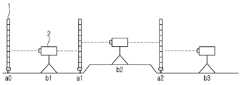
도 1은 종래 표척과 측량기기를 이용하여 수준을 측량하는 방법을 설명하는 도면이다.1 is a diagram illustrating a method of measuring a level using a conventional standard and a measuring instrument.
제1단계로, 표척수(標尺手)가 표척(1)을 고도를 알고 있는 지상기준점(a0)에 세우고, 기계수(機械手)는 일정 거리 떨어진 제1관측점(b1)에서 레벨기 등의 측량기기(2)로 표척(1)의 눈금을 읽는다.In the first stage, the target number 1 is set at the ground reference point (a0) of known altitude, and the number of the machine Read the scale of the target scale (1) with the measuring instrument (2).
제2단계로, 표척수가 제1지점(a1)으로 이동하여 표척(1)을 세우고, 기계수가 관측점(b1)에서 측량기기(2)의 방향을 전환하여 측량기기(2)를 통해 제1지점의 표척 눈금을 읽는다. 여기서 지상기준점(a0)과 제1지점(a1)에서 읽은 눈금의 차와 지상기준점의 고도로부터 제1지점의 고도를 구한다.In the second step, the target number moves to the first point (a1) and sets up the target scale (1), and the machine number changes the direction of the surveying device (2) at the observation point (b1) and passes the first through the surveying device (2) Read the mark scale of the point. Here, the altitude of the first point is obtained from the difference between the scale read at the ground reference point (a0) and the first point (a1) and the altitude of the ground reference point.
제3단계로, 기계수는 제1지점(a1) 뒤의 제2관측점(b2)으로 이동하고, 표척수가 표척(1)을 제자리(제1지점)에서 방향 전환시켜 표척(1)이 측량기기(2)를 바라보도록 하면 기계수가 제2관측점(b2)에서 측량기기로 제1지점(a1)의 표척 눈금을 읽는다.In the third step, the machine number moves to the second viewpoint (b2) behind the first point (a1), and the reference number 1 changes the direction from the original position (the first point) so that the measurement number 1 is surveyed. When looking at the instrument (2), the machine operator reads the scale of the first point (a1) with the measuring instrument from the second observation point (b2).
제4단계로, 표척수가 제2지점(a2)으로 이동하여 표척(1)을 세우고, 기계수가 제2관측점(b2)에서 제2지점(a2)의 표척 눈금을 읽는다. 여기서 제2관측점(b2)에서 읽은 제1지점(a1)과 제2지점(a2)의 눈금 차이로부터 제2지점의 고도를 구한다.In the fourth step, the target number moves to the second point (a2) and sets up the target scale 1, and the machine number reads the scale scale of the second point (a2) at the second observation point (b2). Here, the altitude of the second point is obtained from the difference in scale between the first point (a1) and the second point (a2) read from the second observation point (b2).
이와 같은 방법으로 표척(1)과 측량기기(2)를 계속하여 이동시키면서 각 지점의 표척과 각 관측점에서의 측량기기의 방향을 전환시켜 눈금을 읽어 목표지점까지 각 지점의 고도를 구한다.In this way, while continuously moving the target scale 1 and the
그러나 이러한 종래 측지측량 방법은 측량기기의 설치와 해체를 반복해야 하는 번거로움과 측정 대상 지역에 대한 1회 1 측량의 한계로 인한 시간적 불리함으로 인해 측지측량 작업의 효율을 현저히 저해되는 문제점이 있다.However, such a conventional geodetic surveying method has a problem in that the efficiency of the geodetic surveying operation is significantly impaired due to the inconvenience of having to repeat the installation and dismantling of the surveying equipment and the time disadvantage due to the limitation of one-time survey for the measurement target area.
또한, 종래 측지측량 방법은 일정 구역 단위로 표척과 측량기기를 이용하여 고저를 측량하여야 하므로 지표면의 세밀한 굴곡 상태를 측정하기에는 다소 미흡하다는 문제점이 있다.In addition, the conventional geodetic survey method has a problem in that it is somewhat insufficient to measure the detailed bending state of the ground surface because it is necessary to measure the height and the bottom by using a standard scale and a measuring instrument in units of a certain area.
위의 배경기술로서 설명된 사항들은 본 발명의 배경에 대해 이해 증진을 위한 것일 뿐, 이 기술분야에서 통상의 지식을 가진자에게 이미 알려진 종래기술에 해당함을 인정하는 것으로 받아들여져서는 안 될 것이다.The matters described as the background art above are only for improving understanding of the background of the present invention, and should not be taken as an acknowledgment that they correspond to the prior art already known to those of ordinary skill in the art.
본 발명은 전술한 종래기술의 문제점을 해결하기 위한 것으로서, 차량을 이용하여 용이하게 측지측량 정보를 수집할 수 있는 수준 측량의 정밀도가 향상되고 지표면의 굴곡 상태를 측정할 수 있는 측지측량시스템을 제공하는데 그 목적이 있다.The present invention is to solve the problems of the prior art described above, and provides a geodetic surveying system that can easily collect geodetic survey information using a vehicle and improve the precision of level surveying and measure the curvature of the ground surface but it has a purpose.
또한, 본 발명은 각 지점에 대한 지표면의 정밀한 굴곡 상태를 측정할 수 있는 수준 측량의 정밀도가 향상되고 지표면의 굴곡 상태를 측정할 수 있는 측지측량시스템을 제공하는데 또 다른 목적이 있다.In addition, another object of the present invention is to provide a geodetic surveying system capable of measuring the curved state of the earth's surface and improving the precision of level surveying that can measure the precise curved state of the earth's surface for each point.
본 발명이 이루고자 하는 기술적 과제들은 이상에서 언급한 기술적 과제들로 제한되지 않으며, 언급되지 않은 또 다른 기술적 과제들은 본 발명의 기재로부터 당해 분야에서 통상의 지식을 가진 자에게 명확하게 이해될 수 있을 것이다.The technical problems to be achieved by the present invention are not limited to the technical problems mentioned above, and other technical problems not mentioned will be clearly understood by those of ordinary skill in the art from the description of the present invention. .
위와 같은 목적을 달성하기 위한 본 발명의 구성은, 현장을 운행하는 차량에 설치되어 지표면의 정보를 수집하는 정보수집기; 및 경사도가 0도인 지표면에 설치되며 기준신호를 발신하는 기준좌표발신기; 를 포함하는 것을 특징으로 한다.The configuration of the present invention for achieving the above object includes: an information collector installed in a vehicle running the field to collect information on the ground surface; and a reference coordinate transmitter installed on the ground surface having an inclination of 0 degrees and transmitting a reference signal. It is characterized in that it includes.
본 발명의 실시예에 따른 수준 측량의 정밀도가 향상되고 지표면의 굴곡 상태를 측정할 수 있는 측지측량시스템에서 상기 정보수집기는, 차량에 내장되어 지표면의 굴곡 상태를 감지하는 경사감지기; 차량의 상부에 결합되는 수평조절부; 수평조절부의 상부에 결합되는 착지대; 착지대의 상부에 결합되는 완충기구; 완충기구의 상부에 결합되는 회전기구; 회전기구의 상부에 결합되는 승강부; 및 승강부의 상부에 결합되어 차량 주변을 촬영하는 카메라; 를 포함하는 것이 바람직하다.The information collector in the geodetic surveying system capable of improving the leveling accuracy and measuring the curved state of the ground surface according to an embodiment of the present invention, is built in a vehicle, a slope sensor for detecting the curved state of the ground; a horizontal adjustment unit coupled to the upper portion of the vehicle; a landing platform coupled to the upper part of the horizontal adjustment unit; a buffer mechanism coupled to the upper portion of the landing platform; a rotation mechanism coupled to the upper portion of the buffer mechanism; Elevating unit coupled to the upper portion of the rotating mechanism; and a camera coupled to the upper part of the elevating part to photograph the surroundings of the vehicle; It is preferable to include
본 발명의 실시예에 따른 수준 측량의 정밀도가 향상되고 지표면의 굴곡 상태를 측정할 수 있는 측지측량시스템에서 상기 경사감지기기는, 차량에 고정되는 서포터; 서포터에 회전가능하게 결합되는 축대; 축대에 결합되어 서포터에 회동하도록 된 회동자; 축대의 외면에 밀착되도록 서포터에 결합되어서 축대의 회전을 정지시키는 브레이크; 를 포함하는 것이 바람직하다.The inclination sensor in the geodetic surveying system capable of improving the leveling accuracy and measuring the curvature of the ground surface according to an embodiment of the present invention includes: a supporter fixed to a vehicle; A shaft rotatably coupled to the supporter; a rotator coupled to the shaft and rotated to the supporter; a brake coupled to the supporter so as to be in close contact with the outer surface of the shaft to stop the rotation of the shaft; It is preferable to include
본 발명의 실시예에 따른 수준 측량의 정밀도가 향상되고 지표면의 굴곡 상태를 측정할 수 있는 측지측량시스템에서 상기 수평조절부는, 내부가 비어있는 원통형의 높낮이케이스; 높낮이케이스에 상하로 슬라이딩 가능하도록 수용되며 측면에 다수의 고정홈이 형성되는 높낮이로드; 및 높낮이케이스의 상단에 결합되며 다수의 고정홈으로 진입 가능한 고정로드를 구비하는 높낮이고정부; 를 포함하고, 상기 높낮이고정부는, 높낮이케이스의 상단에 결합되는 고정케이스; 고정케이스에 좌우로 슬라이딩 가능하도록 수용되며 단부가 다수의 고정홈에 진입할 수 있는 고정로드; 고정케이스의 내부에 수용되며 고정로드의 우단과 고정케이스의 내측 우단 사이를 연결하는 고정스프링; 및 고정케이스의 상부에 장착되며 고정로드의 움직임을 제한할 수 있는 고정제한부; 를 포함하며, 상기 고정제한부는, 고정케이스부의 상부면에 결합되는 제한판; 제한판의 상단에 결합되는 한 쌍의 제한스프링; 제한스프링의 하단에 연결되는 링 형태의 제한이동부; 및 제한이동부의 하단에 결합되는 제한로드; 를 포함하는 것이 바람직하다.In a geodetic surveying system capable of improving leveling precision and measuring the curved state of the ground surface according to an embodiment of the present invention, the horizontal adjustment unit includes: a cylindrical height case with an empty interior; a height rod that is accommodated in the height case so as to be slidable up and down and has a plurality of fixing grooves formed on the side thereof; And it is coupled to the upper end of the height case, the height and lowering part having a fixing rod that can enter into a plurality of fixing grooves; Including, the height and the fixed part, the fixed case coupled to the upper end of the height case; a fixed rod which is accommodated in the fixed case to be slidable from side to side and whose ends can enter the plurality of fixing grooves; a fixing spring accommodated in the fixing case and connecting between the right end of the fixing rod and the inner right end of the fixing case; and a fixed limiting unit mounted on the upper portion of the fixed case and capable of restricting the movement of the fixed rod; It includes, wherein the fixed limiting portion, a limiting plate coupled to the upper surface of the fixed case portion; a pair of limiting springs coupled to the top of the limiting plate; Ring-shaped limiting moving part connected to the lower end of the limiting spring; and a limiting rod coupled to the lower end of the limiting moving part; It is preferable to include
본 발명의 실시예에 따른 수준 측량의 정밀도가 향상되고 지표면의 굴곡 상태를 측정할 수 있는 측지측량시스템에서 상기 회전기구는, 승강부의 하단에 결합되어 승강부가 회전할 수 있도록 하는 수평회전부; 및 수평회전부의 하단에 장착되는 회전제어부; 를 포함하며, 상기 수평회전부는, 승강부의 하단에 결합되며 상단과 후단이 개방된 내부가 비어있는 원통형으로 형성되는 회전케이스; 회전케이스 내부에 수용되며 상단이 표척의 하단에 결합되고 하단이 회전케이스의 하단을 관통하여 회전제어부에 수용되는 회전로드; 회전로드의 측부에 돌출 연장되는 회전연장판; 회전케이스의 상단에 형성되며 회전연장판의 상부면과 접촉되는 회전걸림부; 및 회전연장판의 하부면과 회전케이스의 내측 하부면 사이에 배치되는 다수의 회전볼; 을 포함하고, 상기 회전제어부는, 회전케이스부의 하단에 결합되며 회전로드의 하단이 수용되는 제어케이스; 제어케이스의 내부에 수용되며 회전로드와 직교하는 방향으로 이동 가능한 제어로드; 제어로드의 일단에 결합되며 회전로드의 하부에 형성된 다수의 멈춤홈 중 어느 하나에 삽입될 수 있는 멈춤부; 멈춤부와 회전케이스의 내측면 사이에 결합되는 제어스프링; 제어로드의 타단에 결합되며 제어케이스의 측부에 형성된 방지홈의 삽입될 수 있는 방지부; 방지부의 일측에 결합되며 삼각형 형태의 단면을 가지는 제어이동부; 제어케이스의 측부에 결합되며 제어이동부가 좌우로 이동 가능하도록 삽입되는 제어이동케이스; 및 제어이동케이스의 상부에 상하로 이동 가능하도록 결합되며 하단이 제어이동부의 상부면에 접촉되는 제어손잡이; 를 포함하는 것이 바람직하다.In a geodesic surveying system capable of improving the precision of leveling and measuring the curved state of the ground surface according to an embodiment of the present invention, the rotating mechanism includes: a horizontal rotating unit coupled to the lower end of the lifting unit to allow the lifting unit to rotate; and a rotation control unit mounted on a lower end of the horizontal rotation unit; It includes, wherein the horizontal rotating unit is coupled to the lower end of the elevating unit, the rotating case is formed in an empty cylindrical shape with an open upper end and a rear end; a rotating rod accommodated in the rotating case, the upper end being coupled to the lower end of the table chuck, and the lower end passing through the lower end of the rotating case and being accommodated in the rotating control unit; a rotation extension plate protruding from the side of the rotation rod; a rotation stopper formed on the upper end of the rotation case and in contact with the upper surface of the rotation extension plate; and a plurality of rotating balls disposed between the lower surface of the rotating extension plate and the inner lower surface of the rotating case; Including, wherein the rotation control unit is coupled to the lower end of the rotating case portion, the control case in which the lower end of the rotating rod is accommodated; a control rod accommodated in the control case and movable in a direction perpendicular to the rotation rod; a stop portion coupled to one end of the control rod and capable of being inserted into any one of a plurality of stop grooves formed under the rotating rod; a control spring coupled between the stopper and the inner surface of the rotating case; a prevention portion coupled to the other end of the control rod and capable of being inserted into the prevention groove formed on the side of the control case; a control moving unit coupled to one side of the prevention unit and having a triangular cross section; a control moving case coupled to the side of the control case and inserted so that the control moving part can move left and right; and a control handle coupled to the upper part of the control moving case so as to be movable up and down, and the lower end of which is in contact with the upper surface of the control moving part. It is preferable to include
본 발명의 실시예에 따른 수준 측량의 정밀도가 향상되고 지표면의 굴곡 상태를 측정할 수 있는 측지측량시스템에서 상기 승강부는, 회전기구의 상부에 결합되는 승강구동부; 승강구동부의 상부에 결합되며 내부가 비어있는 구형의 승강하우징; 승강구동부에 연결되어 시계방향 또는 반시계방향으로 회전되고 상하로 승강하며 승강하우징의 내부에 배치되는 승강축; 승강축의 외벽에 힌지 결합되는 다수의 승강지지바디; 다수의 승강지지바디의 말단에 인출되게 장착되는 지지바; 지지바의 말단에 마련되어 승강하우징의 내벽에 지지되는 지지롤러; 일측부는 승강지지바디의 내부에 결합되고 타측부는 지지바에 결합되어 지지바를 탄성 지지하는 승강스프링; 및 다수의 승강지지바디를 서로 연결하여 다수의 승강지지바디가 지지될 수 있도록 하는 연결스프링; 을 포함하고, 상기 승강구동부의 작동시 승강 지지 바디, 지지바 및 지지롤러는 승강축과 함께 회전되면서 승강되고, 지지롤러는 승강하우징의 내벽에 구름 접촉되는 것이 바람직하다.In a geodetic surveying system capable of improving leveling precision and measuring the curved state of the ground surface according to an embodiment of the present invention, the lifting unit includes: a lifting driving unit coupled to the upper portion of the rotating mechanism; a spherical elevating housing coupled to the upper part of the elevating drive and having an empty interior; an elevating shaft connected to the elevating drive unit, rotating clockwise or counterclockwise, elevating up and down, and disposed inside the elevating housing; A plurality of lifting support body hinged to the outer wall of the lifting shaft; a support bar mounted to be drawn out at the ends of the plurality of lifting support bodies; a support roller provided at the end of the support bar and supported on the inner wall of the elevating housing; an elevating spring having one side coupled to the inside of the elevating support body and the other side coupled to the support bar to elastically support the support bar; and a connection spring connecting the plurality of lifting support bodies to each other so that the plurality of lifting support bodies can be supported. And, it is preferable that the lifting support body, the support bar, and the support roller are lifted while rotating together with the lifting shaft when the lifting driving unit is operated, and the support roller is in rolling contact with the inner wall of the lifting housing.
위와 같은 구성을 가지는 본 발명은, 차량에 설치된 경사감지기를 통해 지표면의 굴곡 상태를 정밀하게 측정할 수 있으므로 지표면의 고저 정보 및 경사도를 지점별로 용이하면서도 정확하게 수집할 수 있는 효과가 있다.According to the present invention having the above configuration, since the curved state of the ground surface can be precisely measured through the inclination sensor installed in the vehicle, it is possible to easily and accurately collect information on the elevation and the inclination of the ground surface for each point.
도 1은 종래 표척과 측량기기를 이용하여 수준을 측량하는 방법을 설명하는 도면.
도 2는 본 발명의 일실시예에 따른 수준 측량의 정밀도가 향상되고 지표면의 굴곡 상태를 측정할 수 있는 측지측량시스템의 전체적인 구성을 도시한 블록도.
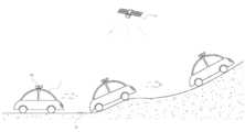
도 3은 본 발명의 일실시예에 따른 차량의 이동 모습을 개략적으로 도시한 도면.
도 4는 본 발명의 일실시예에 따른 차량이 수집한 고저 정보에 따른 지표면의 굴곡 상태를 그래프로 도시한 도면.
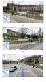
도 5는 본 발명의 일실시예에 따른 측지측량시스템템이 수집한 지상이미지의 출력모습을 보인 이미지.
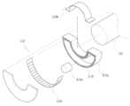
도 6은 본 발명의 일실시예에 따른 경사감지기의 모습을 도시한 사시도.
도 7은 본 발명의 일실시예에 따른 경사감지기를 분해 도시한 사시도.
도 8은 본 발명의 일실시예에 따른 경사감지기의 동작 모습을 보인 단면도.
도 9는 본 발명의 일실시예에 따른 차량의 상부에 카메라가 설치된 모습을 개략적으로 도시한 도면.
도 10은 본 발명의 일실시예에 따른 수평조절부의 단면 모습을 도시한 도면.
도 11은 본 발명의 일실시예에 따른 완충기구의 단면 모습을 도시한 도면.
도 12는 본 발명의 일실시예에 따른 회전기구의 단면 모습을 도시한 도면.
도 13은 본 발명의 일실시예에 따른 회전로드의 모습을 도시한 도면.
도 14는 본 발명의 일실시예에 따른 승강부의 단면 모습을 도시한 도면.1 is a view for explaining a method of measuring a level using a conventional standard and a measuring instrument.
Figure 2 is a block diagram showing the overall configuration of a geodetic surveying system that can measure the curved state of the surface and improved precision of leveling in accordance with an embodiment of the present invention.
3 is a diagram schematically illustrating a moving state of a vehicle according to an embodiment of the present invention;
4 is a graph illustrating a curved state of the ground surface according to height information collected by a vehicle according to an embodiment of the present invention;
5 is an image showing the output state of the ground image collected by the geodetic surveying system according to an embodiment of the present invention.
Figure 6 is a perspective view showing a state of the inclination sensor according to an embodiment of the present invention.
7 is an exploded perspective view of an inclination sensor according to an embodiment of the present invention;
8 is a cross-sectional view showing the operation of the inclination sensor according to an embodiment of the present invention.
9 is a view schematically illustrating a state in which a camera is installed on an upper portion of a vehicle according to an embodiment of the present invention.
10 is a view showing a cross-sectional view of a horizontal adjustment unit according to an embodiment of the present invention.
11 is a view showing a cross-sectional view of a buffer mechanism according to an embodiment of the present invention.
12 is a view showing a cross-sectional view of a rotating mechanism according to an embodiment of the present invention.
13 is a view showing a state of a rotating rod according to an embodiment of the present invention.
14 is a view showing a cross-sectional view of a lifting unit according to an embodiment of the present invention.
이하, 첨부된 도면에 의거하여 본 발명에 대하여 본 발명이 속하는 기술 분야에서 통상의 지식을 가진 자가 용이하게 실시할 수 있도록 상세히 설명한다. 그러나 본 발명은 여러 가지 상이한 형태로 구현될 수 있으며 여기에서 설명하는 실시예에 한정되지 않는다.Hereinafter, based on the accompanying drawings, the present invention will be described in detail so that those of ordinary skill in the art can easily carry out the present invention. However, the present invention may be embodied in many different forms and is not limited to the embodiments described herein.
본 발명을 명확하게 설명하기 위해서 설명과 관계없는 부분은 생략하였으며, 명세서 전체를 통하여 동일 또는 유사한 구성요소에 대해서는 동일한 참조 부호를 붙이도록 한다.In order to clearly explain the present invention, parts irrelevant to the description are omitted, and the same reference numerals are given to the same or similar elements throughout the specification.
또한, 본 명세서 및 특허청구범위에 사용된 용어나 단어는 통상적이거나 사전적인 의미로 한정하여 해석되어서는 안 되며, 발명자는 그 자신의 발명을 가장 최선의 방법으로 설명하기 위해 용어의 개념을 적절하게 정의할 수 있다는 원칙에 입각하여 본 발명의 기술적 사상에 부합하는 의미와 개념으로 해석되어야만 한다.In addition, the terms or words used in the present specification and claims should not be construed as being limited to their ordinary or dictionary meanings, and the inventor should properly understand the concept of the term in order to best describe his invention. Based on the principle that it can be defined, it should be interpreted as meaning and concept consistent with the technical idea of the present invention.
도 2는 본 발명의 일실시예에 따른 수준 측량의 정밀도가 향상되고 지표면의 굴곡 상태를 측정할 수 있는 측지측량시스템의 전체적인 구성을 도시한 블록도이고, 도 3은 본 발명의 일실시예에 따른 차량의 이동 모습을 개략적으로 도시한 도면이며, 도 4는 본 발명의 일실시예에 따른 차량이 수집한 고저 정보에 따른 지표면의 굴곡 상태를 그래프로 도시한 도면이고, 도 5는 본 발명의 일실시예에 따른 측지측량시스템템이 수집한 지상이미지의 출력모습을 보인 이미지이다.2 is a block diagram showing the overall configuration of a geodetic surveying system capable of improving the precision of leveling and measuring the curvature of the ground surface according to an embodiment of the present invention, and FIG. 3 is an embodiment of the present invention. It is a diagram schematically showing the movement of a vehicle according to the present invention, and FIG. 4 is a diagram illustrating a curved state of the ground surface according to the height information collected by the vehicle according to an embodiment of the present invention, and FIG. 5 is a diagram of the present invention It is an image showing the output state of the ground image collected by the geodetic surveying system according to an embodiment.
도시된 바와 같이, 본 발명에 따른 수준 측량의 정밀도가 향상되고 지표면의 굴곡 상태를 측정할 수 있는 측지측량시스템은 현장을 운행하는 차량(V)에 설치되어 지표면의 정보를 수집하는 정보수집기(100) 및 경사도가 0도인 지표면에 설치되며 기준신호를 발신하는 기준좌표발신기(30)를 포함하여 이루어진다.As shown, the geodetic surveying system capable of improving the precision of leveling according to the present invention and measuring the curvature of the ground surface is installed in a vehicle (V) operating the field and collects information on the ground surface (100) ) and a reference coordinate
상기 기준좌표발신기(30)는 기준점의 기능 수행을 위해 설치위치에 대한 GPS좌표가 기록되고, 해당 기록은 작업자에게 제공되어서, 차량(V)을 이용해 지리정보 수집시 좌표확인은 물론 경사감지기(130)의 오차 여부 확인 기준으로 활용된다.The reference coordinate
상기 정보수집기(100)는, 주행중인 차량(V)의 현 위치를 확인하기 위한 GPS수신기(110), 현장을 촬영해서 실사이미지를 확보하는 카메라(120), 지표면의 굴곡 상태를 감지하는 경사감지기(130), 실사이미지 및 지표면의 굴곡 상태가 반영된 그래프를 GPS좌표와 링크해 저장하는 저장장치(140), 차량(V)의 현재 고도를 측정하는 고도계(160), 차량(V)의 주행거리장치(20)와 연동하면서 차량(V)의 주행거리를 확인하는 주행거리확인장치(180), 경사감지기(130)가 감지한 지표면의 굴곡 상태(경사도)와 고도계(160)가 감지한 고도와 주행거리확인장치(180)가 확인한 차량(V)의 주행거리를 통해 지표면의 굴곡 상태를 연산처리하고 이를 2차원 지형이미지에 적용해서 3차원 지형이미지로 완성하는 한편 기준좌표발신기(30)로부터 발신되는 기준신호를 수신해서 경사감지기(130)가 전송한 현재감지신호와 비교해 오차 여부를 판단하는 제어장치(170), 작업자가 정보수집기(100)의 조작을 위해 조작신호를 입력하고 정보수집기(100)의 출력신호를 받아 출력하는 입출력장치(150), 기준좌표발신기(30)가 기준신호를 발신하도록 구동신호를 발신하는 신호발신기(190)를 포함한다.The
또한, 후술하는 바와 같이, 상기 정보수집기(100)는 차량(V)의 상부에 결합되는 수평조절부(300), 수평조절부(300)의 상부에 결합되는 착지대(400), 착지대(400)의 상부에 결합되는 완충기구(200), 완충기구(200)의 상부에 결합되는 회전기구(500), 회전기구(500)의 상부에 결합되는 승강부(600)를 더 포함한다. 상기 카메라(120)는 승강부(600)의 상부에 결합된다.In addition, as will be described later, the
상기 수평조절부(300), 착지대(400), 완충기구(200), 회전기구(500) 및 승강부(600)의 구체적인 구성은 아래에서 상세히 살펴보기로 한다.Specific configurations of the
GPS수신기(110)는 하나 이상의 GPS 전용 인공위성(10) 등과 통신하는 공지,공용의 장치로서, 차량(V)의 현재 GPS좌표를 확인해서 수집한 정보인 상기 실사이미지 및 지표면의 굴곡 상태를 도시한 그래프에 이를 링크한다.The
GPS수신기(110)는 현재 자신이 위치한 GPS좌표를 추적할 수 있는 공지,공용의 장치이므로, 여기서는 인공위성(10)과의 통신을 위한 방법과, GPS좌표를 추적하는 방법 및 이를 위한 전기,전자 및 기계적 구성에 대한 구체적인 설명은 생략한다.Since the
카메라(120)는 하나 이상이 차량(V)에 설치되어서 주행 중 지상의 다양한 방향을 동시에 촬영하도록 된다. 도 5(a)는 차량의 전방 우측을 촬영한 이미지이고, 도 5(b)는 차량의 후방 우측을 촬영한 이미지이며, 도 5(c)는 차량의 전방 정면을 촬영한 이미지이다.One or
경사감지기(130)는 차량(V) 주행 중의 기울어짐을 감지해서 지표면의 경사를 확인하는 것으로서, 본 발명에 따른 경사감지기(130)에 대한 구체적인 구조는 아래에서 보다 상세히 설명한다.The
고도계(160)는 차량(V)이 현재 위치한 고도를 측정해서 경사감지기(130)가 감지한 지표면의 경사도와 실제 경사도의 일치 여부를 비교할 수 있도록 하는 것으로서, 고도의 변함은 없지만 경사감지기(130)가 경사를 인식하도록 하는 과속방지턱 또는 차도에서 인도로의 진입 등과 같은 지상구조물을 식별할 수 있을 것이다.The
주행거리확인장치(180)는 차량(V)의 주행거리장치(20)와 연동하면서 차량(V)이 주행하는 거리를 확인하는 것으로서, GPS수신기(110)와 연동하면서 차량(V)의 주행거리에 대한 정보를 수집할 수도 있을 것이다.The
여기서 주행거리장치(20)는 차량(V)의 차축 등에 연결되어서, 차축의 회전 수 등을 카운트해 차량(V)의 이동거리를 추정하는 공지,공용의 장치로서, 차량(V)의 주행거리 측정에 대한 정확성은 그리 높지 못하다. 따라서 주행거리에 대한 보다 정확한 정보를 수집하기 위해 전술한 바와 같이 주행거리확인장치(180)는 GPS수신기(110)로부터 이동거리에 대한 정보를 수집할 수도 있을 것이다.Here, the
신호발신기(190)는 기준좌표발신기(30)가 근접한 차량(V)을 향해 기준신호를 발신할 수 있도록 구동신호를 발신한다. 신호발신기(190)와 기준좌표발신기(30)는 RFID(Radio-Frequency Identification) 기술을 응용한 것으로서, 신호발신기(190)와 제어장치(170)는 RFID 판독기의 기능을 수행하고, 기준좌표발신기(30)는 RFID 태그의 기능을 수행한다.The
또한, 본 발명에서는 지표면에 항시 설치되는 기준좌표발신기(30)의 동작을 위해 판독기 파트의 동력만을 이용하는 수동형(Passive) RFID 기술을 적용한다. 따라서, 신호발신기(190)로부터 동력원을 포함한 구동신호가 발신되면, 기준좌표발신기(30)는 해당 지표면의 경사도가 0도임을 알리는 기준신호를 발신해서 해당 차량(V)의 제어장치(170)가 이를 수신할 수 있도록 한다.In addition, in the present invention, passive RFID technology that uses only the power of the reader part for the operation of the reference coordinate
참고로, 차량(V)이 기준신호를 제 위치에서 정확히 수신해 인식할 수 있도록 상기 기준신호의 전송 유효반경은 한정되도록 하는 것이 바람직하다. 즉, 경사도가 0도가 아닌 지표면에서 해당 차량(V)이 기준신호를 수신해 이를 수정할 경우, 다른 지표면에서의 경사도 측정에서 오류가 지속적으로 발생할 것이므로, 해당 차량(V)과 기준좌표발신기(30)는 매우 인접한 거리에서 유효한 통신이 이루어져야 하는 것이다.For reference, it is preferable that the effective radius of transmission of the reference signal is limited so that the vehicle V can accurately receive and recognize the reference signal at the position. That is, if the vehicle (V) receives the reference signal and corrects it on the ground surface with an inclination other than 0 degrees, an error will occur continuously in the slope measurement on other ground surfaces, so the vehicle (V) and the reference coordinate
제어장치(170)는 경사감지기(130)와 고도계(160)와 주행거리확인장치(180)가 각각 확인한 정보를 조합해서 해당 지표면의 굴곡 상태(경사도)를 연산해서 이를 도화하는 것으로서, 최종적으로 도 4와 같은 그래프 형태로 도 3의 지표면을 표현할 수 있을 것이다.The
이를 좀 더 구체적으로 설명하면, 경사감지기(130)는 차량(V)의 기울어진 각도(이하 '경사도')를 실시간 측정해서 감지신호로 제어장치(170)에 전송하고, 주행거리확인장치(180)는 차량(V)의 현재 주행거리를 실시간으로 확인해서 제어장치(170)에 전송한다.To explain this in more detail, the
제어장치(170)는 주행거리확인장치(180)가 전송하는 주행거리를 실시간으로 도시하되 경사감지기(130)가 전송한 경사도로 도시해서 그래프를 완성한다. 이때, 경사감지기(130)가 전송한 경사도에 변화가 있음에도 불구하고 고도계(160)에서 전송한 고도 정보에 변화가 없다면 지표면에 형성된 인공구조물에 의한 일시적인 경사도 변화이므로, 제어장치(170)는 경사도 방향을 변경하지 않고 전술한 도시를 속행할 수 있을 것이다.The
결국 제어장치(170)는 거리(D) 대비 높이(H)에 대한 지표면의 굴곡을 정밀하게 도시할 수 있고, 이를 정확하게 반영해서 사용자에게 효용성 높은 정보를 제공할 수 있게 된다.As a result, the
한편, 제어장치(170)는 기준좌표발신기(30)로부터 기준신호를 수신하면, 경사감지기(130)로부터 수신한 감지신호의 경사도를 확인해서 0도인지 여부를 확인하고, 그렇지 않은 경우 경사감지기(130)의 브레이크(134)를 해제할 수 있도록 이상신호를 입출력장치(150)를 통해 출력한다. 물론, 작업자는 입출력장치(150)를 통해 출력되는 이상신호를 확인하면 브레이크(134)를 해제해서 경사도가 0도인 해당 위치에서 경사감지기(130)의 초기화를 재설정할 것이다.On the other hand, when the
도 6은 본 발명의 일실시예에 따른 경사감지기의 모습을 도시한 사시도이고, 도 7은 본 발명의 일실시예에 따른 경사감지기를 분해 도시한 사시도이며, 도 8은 본 발명의 일실시예에 따른 경사감지기의 동작 모습을 보인 단면도이다.6 is a perspective view showing a state of the inclination sensor according to an embodiment of the present invention, FIG. 7 is an exploded perspective view of the inclination sensor according to an embodiment of the present invention, and FIG. 8 is an embodiment of the present invention. It is a cross-sectional view showing the operation of the inclination sensor according to
상기 경사감지기(130)는 차량(V)에 설치되어서 차량(V)이 통행하는 지표면의 경사도를 감지하는 것으로서, 차량(V)의 차체에 고정되는 서포터(131)와, 서포터(131)에 회전가능하게 고정되는 축대(132)와, 축대(132)를 매개로 서포터(131)에 회동가능하게 고정되는 회동자(133)와, 축대(132)의 회전을 선택적으로 정지시키는 브레이크(134)를 포함한다.The
서포터(131)는 원형 바(bar) 형상의 축대(132)를 회전가능하게 고정하면서 상기 차체에 고정될 수 있는 구조라면 도시한 형상에 한정하는 것은 아니며, 이하의 청구범위를 벗어나지 않는 한도 내에서 다양하게 변형실시될 수 있을 것이다.The
축대(132)는 전술한 바와 같이 원형 바 형상을 이루고 서포터(131)에 회전가능하게 고정된다. 축대(132)는 서포터(131)와의 원활한 회전을 위해서 베어링(미도시함)이 구성될 수도 있고, 둘레면에 마찰을 낮추는 부재가 도포되어서 서포터(131)와의 마찰을 최소화시킬 수도 있을 것이다.The
회동자(133)는 호 형상의 중공을 갖는 하우징(133a)과, 하우징(133a)을 축대(132)에 고정하기 위한 고리(133b)와, 상기 중공의 바닥면을 따라 배치되는 다수의 압력센서(133c)와, 상기 중공을 따라 이동하면서 압력센서(133c)를 가압하는 롤러(133d)와, 상기 중공의 천장면을 따라 배치되면서 롤러(133d)의 이동과 회전을 원활히 하는 활차(133e)를 포함한다.The
하우징(133a)은 호 형상의 중공을 가지며, 롤러(133d)가 이동할 수 있도록 일정한 폭으로 형성된다. 여기서, 원기둥 형상의 롤러(133d)는 상기 중공을 따라 회전하면서 이동하는데, 이는 하우징(133a)이 차량(V)의 기울어짐을 따라 기울어지면서 중공의 최저점에 변화를 일으키고, 중력에 영향을 받는 롤러(133d)는 상기 최저점을 향해 상기 중공의 길이방향을 따라 이동하기 때문이다.The housing (133a) has an arc-shaped hollow and is formed with a constant width so that the roller (133d) can move. Here, the
고리(133b)는 하우징(133a)을 축대(132)에 고정하는 것으로서, 서포터(131)를 기준으로 회전하는 축대(132)를 따라 하우징(133a)이 회전할 수 있도록 한다. 참고로, 하우징(133a)과 축대(132)는 고리(133b)를 매개로 한 고정 방식에 한정하지 않으며, 축대(132)와 하우징(133a)을 일체로 형성시키는 방식, 볼팅 또는 핀 등과 같은 별도의 체결수단을 매개로 고정하는 방식 등의 다양한 방식이 적용될 수 있을 것이다.The
압력센서(133c)는 상기 중공의 바닥면을 따라 다수 개가 일렬로 배치되어서, 롤러(133d)의 하중을 감지하고, 해당 감지신호를 자신의 ID와 함께 제어장치(170)로 전송한다.A plurality of
압력센서(133c)는 롤러(133d)의 현재 위치를 확인해서 제어장치(170)가 하우징(133a)의 현재 자세를 추적할 수 있도록 하고, 더 나아가 회동자(133)의 자세 및 차량(V)의 자세를 추적해서, 차량(V)이 위치한 지표면의 경사도를 추적할 수 있도록 한다. 이를 위해 압력센서(133c)는 상기 바닥면을 따라 일정한 각도 또는 일정한 간격으로 배치되는 것이 바람직하고, 세밀한 측정을 위해 다수 개가 촘촘하게 배치되는 것이 바람직할 것이다.The
참고로, 압력센서(133c)가 1도 간격으로 일렬배치되었다면, 압력센서(133c)로부터 순차적으로 감지신호를 수신한 제어장치(170)는 회동자(133)가 현재 1도씩 기울어지고 있음을 인식할 수 있을 것이고, 이를 통해 차량(V)의 정확한 경사도를 추적할 수 있을 것이다.For reference, if the
롤러(133d)는 상기 중공의 폭에 상응하는 직경을 갖는 원기둥 형상을 이루면서 상기 중공에 회전가능하게 고정되는 것으로서, 압력센서(133c)에 지속적인 하중을 가할 수 있는 충분한 중량을 갖는 재질로 된다.The
따라서, 롤러(133d)는 하우징(133a)의 기울어짐을 따라 상기 중공의 최저점을 향해 굴러 이동하고, 해당 최저점에 위치한 압력센서(133c)에 하중을 가해서 해당 압력센서(133c)가 이를 감지할 수 있도록 한다.Therefore, the
활차(133e)는 상기 중공의 천장면을 따라 일렬로 회전가능하게 배치되어서, 상기 중공을 따라 이동하는 롤러(133d)가 상기 천장면과의 마찰 없이 원활히 회전해 이동할 수 있도록 하는 동시에 롤러(133d)가 상기 중공을 따라 이동하는 동안 압력센서(133c)에 정확히 밀착해 가압할 수 있도록 압력을 가한다.The
이때 서로 이웃하는 활차(133e)는 상호 간의 간섭을 방지하기 위해 이격하게 배치된다. 계속해서, 본 발명에 따른 활차(133e)는 롤러(133d)와의 밀착이 효율적으로 이루어지도록 하기 위해서 회전축(a; 도 8 참고)을 매개로 하우징(133a)의 상기 천장면에 상하로 이동가능하게 고정된다. 따라서, 롤러(133d)와 직접 접하는 활차(133e)는 도 8에 도시한 바와 같이 하우징(133a)의 자세에 상관없이 상방으로 이동하고, 그 이외의 활차(133e)는 자중에 의해 하방으로 이동해 최저점에 위치한다.In this case, the
브레이크(134)는 축대(132)의 외면에 밀착되도록 서포터(131)에 고정되어서 입출력장치(150)에 의해 조작된다. 이를 좀 더 구체적으로 설명하면, 서포터(131)는 차량(V)의 현재 자세에 따라 그 경사도에 변화가 있는 반면, 회동자(133)는 서포터(131)에 회전가능하게 고정된 축대(132)에 의해 항시 수평 자세를 유지한다.The
즉, 회동자(133)는 자중에 의해 서포터(131)의 경사도에 상관없이 항시 중력방향으로 그 위치가 고정되는 것이다. 그러나, 측지측량 작업을 위해 차량(V)의 주행이 시작되면, 회동자(133) 또한 서포터(131)의 경사도 변화를 따라 기울어져야 한다.That is, the position of the
이를 위해 측량 준비 중에는 브레이크(134)가 해제되어 회동자(133)가 서포터(131)로부터 독립돼 원활히 회전할 수 있고, 측량 준비가 완료되고 시작을 위한 고정신호가 입출력장치(150)로부터 입력되면 브레이크(134)는 축대(132)를 고정해서 회동자(133)가 서포터(131)에 구속되도록 한다.To this end, the
본 발명에 따른 브레이크(134)는 축대(132)의 회전을 저지할 수 있는 구조라면 다양한 수단이 적용될 수 있을 것이나, 본 발명에 따른 실시 예에서는 축대(132)의 둘레면에 밀착되어서 축대(132)의 회전을 따라 회전하는 마찰계수가 큰 재질의 패드(134b)와, 패드(134b)를 회전가능하게 고정하면서 서포터(131)에 설치되고 상기 고정신호 수신시 패드(134b)가 회전하지 못하도록 잡는 그랩퍼(134a)로 구성된다.As long as the
결국, 롤러(133d)의 초기 위치가 잡힌 상태에서 현장 측량이 시작되고, 차량(V)이 지표면이 'θ'로 경사진 도로를 통과할 경우 회동자(133) 또한 'θ' 만큼 기울어지면서 롤러(133d)가 자중에 의해 이동할 수 있도록 될 것이다. 물론, 압력센서(133c)는 롤러(133d)의 이동에 따른 압력을 감지하고, 이렇게 감지된 감지신호는 제어장치(170)로 실시간 전송된다.As a result, the field survey is started with the initial position of the
한편, 차량(V)이 처음 출발하는 위치의 지표면 경사도가 수평한 0도가 아닐 수 있다. 그런데, 회동자(133)는 지표면의 경사도와는 상관없이 수평상태로부터 시작하므로, 작업자는 상기 출발 위치의 초기 경사도를 우선 측정해서 제어장치(170)에 입력하고, 제어장치(170)는 압력센서(133c)로부터 전송되는 감지신호를 상기 초기 경사도를 기준으로 보정해 처리한다.On the other hand, the inclination of the ground surface of the position where the vehicle V first starts may not be 0 degrees horizontally. However, since the
이상 설명한 바와 같이 차량(V)은 지표면의 경사도를 따라 기울어지면서 회동자(133) 또한 기울어지므로, 롤러(133d)는 상기 중공을 따라 이동하면서 압력센서(133c)를 순차 가압하게 되고, 압력센서(133c)는 롤러(133d)의 압력을 감지해 해당 감지신호를 자신의 ID와 함께 제어장치(170)로 전송해서 제어장치(170)가 차량(V)의 기울어짐 여부와 그 경사도를 정확히 연산, 추적할 수 있도록 한다.As described above, as the vehicle V is inclined along the inclination of the ground surface and the
물론 전술한 바와 같이 제어장치(170)는 주행거리확인장치(180)가 확인하는 차량(V)의 주행거리를 수신해서 도 4에 도시한 바와 같은 그래프를 도시하고, 이를 통해 차량(V)이 주행한 지표면의 굴곡 상태를 도시할 수 있다.Of course, as described above, the
본 발명에 따른 지표면의 굴곡 측량 방식은 주행중인 차량(V)을 통해 이루어지므로, 차량(V)이 정차와 주행을 반복하는 과정에서 롤러(133d)에 관성이 작용할 수 있고, 이를 통해 지표면의 굴곡 상태와는 상관없이 롤러(133d)는 하우징(133a)의 중공을 따라 이동할 수 있다. 물론, 롤러(133d)의 이러한 이동은 압력센서(133c)를 가압하게 되고, 압력센서(133c)는 이를 감지해 제어장치(170)로 전송하므로, 제어장치(170)는 해당 지표면에 대해 잘못된 정보를 수집할 수 있다.Since the curvature surveying method of the ground surface according to the present invention is performed through the vehicle V in motion, inertia may act on the
이러한 문제를 해소하기 위해 활차(133e)를 회전가능하게 고정하는 회전축(a)은 하우징(133a)에 형성된 이동홈(b)으로 이동가능하게 삽입되고, 상기 중공에 인접한 이동홈(b)의 하단에는 서로 대향하게 돌출된 걸림홈(c)이 형성된다.In order to solve this problem, the rotating shaft (a) for rotatably fixing the pulley (133e) is movably inserted into the moving groove (b) formed in the housing (133a), and the lower end of the moving groove (b) adjacent to the hollow. The engaging grooves (c) protruding to face each other are formed.
결국, 회전축(a)은 이동홈(b)을 따라 이동하면서 활차(133e)가 상기 중공으로 인입출되도록 하고, 롤러(133d)에 의해 측력을 받을 경우 회전축(a)이 걸림홈(c)으로 유입되면서 도 8(a)에 도시한 바와 같이 활차(133e)가 상기 중공으로 돌출된 상태를 유지하도록 한다. As a result, the rotary shaft (a) moves along the moving groove (b) so that the pulley (133e) is drawn into and out of the hollow, and when the lateral force is received by the roller (133d), the rotary shaft (a) moves into the engaging groove (c). As shown in FIG. 8( a ), the
이를 좀 더 구체적으로 설명하면, 이동홈(b)은 호 형상을 한 상기 중공에서 상기 호의 원 지름 방향을 따라 길게 형성된다. 이때, 이동홈(b)에 이동가능하게 고정된 회전축(a)이 상기 중공으로부터 가장 이격되면서 활차(133e)가 상기 중공에 인입되더라도 롤러(133d)와의 긴밀한 맞물림 상태가 유지되도록 한다. 물론, 그 반대로 회전축(a)이 상기 중공에 가장 근접되면서 활차(133e)가 상기 중공에 인출되면 롤러(133d)는 인출된 활차(133e)에 걸려서 그 이동이 방해될 것이다.To explain this in more detail, the moving groove (b) is formed to be elongated in the arc-shaped hollow along the circular radial direction of the arc. At this time, the rotation shaft (a) movably fixed to the moving groove (b) is most spaced apart from the hollow so that even if the pulley (133e) is drawn into the hollow, close engagement with the roller (133d) is maintained. Of course, on the contrary, when the
계속해서, 상기 중공과 근접한 이동홈(b)의 하단에는 서로 대향하게 돌출된 걸림홈(c)이 형성된다. 전술한 바와 같이, 롤러(133d)와 접하고 있는 활차(133e)를 제외한 남은 활차는 자중에 의해 하방으로 이동해서 상기 중공에 돌출되고, 결국 해당 활차의 회전축(a)은 해당 이동홈(b)의 하단에 위치한다.Subsequently, at the lower end of the moving groove (b) close to the hollow, engaging grooves (c) protruding to face each other are formed. As described above, the remaining pulleys except for the
그런데, 차량(V)이 정차 또는 출발하면서 관성을 받은 롤러(133d)가 중공을 따라 이동하면, 상기 활차는 롤러(133d)에 의해 도 8(a)에 도시한 바와 같이 측력을 받게 되고, 측력을 받은 상기 활차의 회전축(a)은 걸림홈(c)으로 유입된다.However, when the
이 상태에서 롤러(133d)의 이동이 지속되면, 롤러(133d)의 회전은 상기 활차에 전달되고, 상기 활차는 그 회전에 맞물려 회전하면서 걸림홈(c)으로 더욱 파고들어 롤러(133d)의 이동을 저지한다. 결국, 롤러(133d)는 관성에 의한 이동을 저지받고 현위치를 벗어나지 못하며, 제어장치(170)는 항상 일정한 감지신호를 수신할 수 있다.In this state, if the movement of the
한편, 하우징(133a)의 기울어짐에 의한 정상적인 롤러(133d) 이동의 경우, 롤러(133d)는 활차(133e)를 직하방에서 밀어올리고, 활차(133e)의 회전축(a)은 걸림홈(c)의 측면을 따라 이동홈(b)으로 이동해 상방 이동하면서, 도 8(b)에 도시한 바와 같이 롤러(133d)는 간섭 없는 원활한 이동을 하게 된다.On the other hand, in the case of normal movement of the
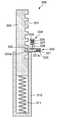
도 9는 본 발명의 일실시예에 따른 차량의 상부에 카메라가 설치된 모습을 개략적으로 도시한 도면이고, 도 10은 본 발명의 일실시예에 따른 수평조절부의 단면 모습을 도시한 도면이다.9 is a diagram schematically illustrating a state in which a camera is installed on an upper portion of a vehicle according to an embodiment of the present invention, and FIG. 10 is a view showing a cross-sectional view of a horizontal adjustment unit according to an embodiment of the present invention.
도시된 바와 같이, 상기 정보수집기(100)는, 차량(V)에 내장되어 지표면의 굴곡 상태를 감지하는 경사감지기(130), 차량(V)의 상부에 결합되는 수평조절부(300), 수평조절부(300)의 상부에 결합되는 착지대(400), 착지대(400)의 상부에 결합되는 완충기구(200), 완충기구(200)의 상부에 결합되는 회전기구(500), 회전기구(500)의 상부에 결합되는 승강부(600) 및 승강부(600)의 상부에 결합되어 차량 주변을 촬영하는 카메라(120)를 포함한다.As shown, the
도시된 실시예에서 상기 수평조절부(300)는 하나만 도시되어 있으나, 이는 측면에서 바라본 모습을 도시하기 위해 편의상 하나만 표현한 것이며, 차량(V)의 상부에 좌우로 한 쌍이 설치되어 카메라(120)가 수평을 이룰 수 있도록 한다.In the illustrated embodiment, only one
상기 수평조절부(300)는, 내부가 비어있는 원통형의 높낮이케이스(310), 높낮이케이스(310)에 상하로 슬라이딩 가능하도록 수용되며 측면에 다수의 고정홈(321)이 형성되는 높낮이로드(320) 및 높낮이케이스(310)의 상단에 결합되며 다수의 고정홈(321)으로 진입 가능한 고정로드(332)를 구비하는 높낮이고정부(330)를 포함하여 이루어진다.The
상기 높낮이케이스(310)는 챠량(V)의 상면에 놓이며, 내부에 높낮이스프링(311)이 수용된다. 높낮이스프링(311)은 높낮이로드(320)의 하단과 높낮이케이스(310)의 내측 하단 사이를 연결하며, 높낮이로드(320)가 상부로 이동할 수 있도록 탄성력을 제공한다.The
상기 높낮이로드(320)는 높낮이케이스(310)에 상하로 이동 가능하도록 결합되며, 높낮이로드(320)의 상하 이동에 따라 그 상부에 결합된 착지대(400)의 높낮이도 가변될 수 있으며, 이에 따라 착지대(400)를 수평으로 조절할 수 있다.The
상기 높낮이고정부(330)는, 높낮이케이스(310)의 상단에 결합되는 고정케이스(331), 고정케이스(331)에 좌우로 슬라이딩 가능하도록 수용되며 단부가 다수의 고정홈(321)에 진입할 수 있는 고정로드(332), 고정케이스(331)의 내부에 수용되며 고정로드(332)의 우단과 고정케이스(331)의 내측 우단 사이를 연결하는 고정스프링(333) 및 고정케이스(331)의 상부에 장착되며 고정로드(332)의 움직임을 제한할 수 있는 고정제한부(334)를 포함하여 이루어진다.The
상기 고정케이스(331)는 내부가 비어있으며, 고정로드(332)를 수용할 수 있다. 고정케이스(331)의 상부면에는 후술되는 고정제한부(334)의 제한로드(338)가 진입할 수 있도록 제한홀(331a)이 형성된다.The fixing
상기 고정로드(332)는 고정케이스(331)에 좌우로 이동 가능하도록 결합되며, 고정로드(332)의 단부는 쐐기 형태로 형성되어 있다. 고정로드(332)의 단부가 쐐기 형태로 형성되어 있으므로 고정로드(332)는 높낮이로드(320)에 형성된 다수의 고정홈(321)을 타고 넘을 수 있다.The fixing
즉, 높낮이로드(320)가 상하로 이동할 때, 고정로드(332)는 고정홈(321)이 위치한 부분에서는 좌측으로 이동하고, 고정홈(321)이 위치하지 않은 부분에서는 높낮이로드(320)의 외측면에 접촉되어 우측으로 이동하게 된다.That is, when the
상기 고정스프링(333)에 의해 고정로드(332)는 좌우로 이동하였다가 원래 위치로 복귀할 수 있다. 고정로드(332)의 상부면에는 고정케이스(331)의 제한홀(331a)에 대응하는 위치에 로드홈(332a)이 형성된다. 이러한 로드홈(332a) 역시 후술되는 고정제한부(334)의 제한로드(338)가 진입할 수 있다.The fixing
상기 고정제한부(334)는, 고정케이스(331)의 상부면에 결합되는 제한판(335), 제한판(335)의 상단에 결합되는 한 쌍의 제한스프링(336), 제한스프링(336)의 하단에 연결되는 링 형태의 제한이동부(337) 및 제한이동부(337)의 하단에 결합되는 제한로드(338)를 포함하여 이루어진다.The
상기 한 쌍의 제한스프링(336)은 제한이동부(337) 및 제한로드(338)가 하부로 이동될 수 있도록 탄성력을 가한다. 상기 제한로드(338)는 고정케이스(331)의 제한홀(331a) 및 고정로드(332)의 로드홈(332a)에 진입할 수 있다.The pair of limiting
본 발명에 따른 수평조절부(300)의 수평 조절 과정을 살펴보면, 먼저 제한이동부(337)가 한 쌍의 제한스프링(336)의 탄성력을 극복하고 상부로 이동된다. 제한이동부(337)의 이동에 따라 제한로드(338) 역시 제한홀(331a) 및 로드홈(332a)으로부터 이탈되고, 고정로드(332)는 자유롭게 좌우로 움직일 수 있게 된다.Looking at the horizontal adjustment process of the
그 다음, 높낮이로드(320)를 상하로 슬라이딩 이동시켜 높낮이로드(320)가 높낮이케이스(310)에 삽입되는 정도를 결정한다. 이때, 높낮이스프링(311)은 높낮이로드(320)가 상부로 이동할 수 있도록 탄성력을 제공한다.Next, by sliding the
상기 높낮이로드(320)가 상하로 이동될 때 고정로드(332)는 다수의 고정홈(321)을 타고 넘을 수 있으며, 고정홈(321)이 위치한 부분에서는 좌측으로 이동하고, 고정홈(321)이 위치하지 않은 부분에서는 높낮이로드(320)의 외측면에 접촉되어 우측으로 이동하게 된다.When the
상기 높낮이로드(320)의 높낮이가 결정되면, 제한이동부(337)를 놓아 제한스프링(336)의 탄성력에 의해 제한로드(338)가 하부로 이동되도록 하고, 제한로드(338)의 하단은 제한홀(331a) 및 로드홈(332a)에 삽입되어 고정로드(332)가 더 이상 이동되지 않도록 한다.When the height of the lifting
이에 따라 착지대(400)는 더 이상 상하로 움직이지 않고 높낮이가 고정되며, 다수의 수평조절부(300)의 높낮이를 조절하여 착지대(400)를 수평으로 유지할 수 있다.Accordingly, the
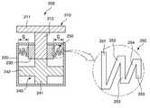
도 11은 본 발명의 일실시예에 따른 완충기구의 단면 모습을 도시한 도면이다.11 is a view showing a cross-sectional view of a buffer mechanism according to an embodiment of the present invention.
도시된 바와 같이, 상기 완충기구(200)는 완충로드(210), 완충케이스(220), 완충스토퍼(230), 완충연결부(240) 및 완충굴곡부(250)를 포함하여 이루어지며, 회전기구(500)의 하단에 장착된다.As shown, the
상기 완충로드(210)는 회전기구(500)의 하단에 결합되며, 원판 형태의 완충체결부(211) 및 완충체결부(211)의 하부 중앙에 연장되는 원통 형태의 완충원통부(212)로 이루어진다.The
상기 완충케이스(220)는 내부가 비어있는 원통형으로 형성되며, 완충로드(210)의 하단이 수용된다. 이러한 완충케이스(220)의 하단에는 착지대(400)가 결합된다.The
상기 완충스토퍼(230)는 완충로드(210)의 완충원통부(212)의 하부 외측면에 결합된다. 완충스토퍼(230)는 링 형태로 형성되며, 완충케이스(220)의 내부에 배치되어 있다. 지면으로부터 큰 진동이나 충격이 가해져서 완충로드(210)가 크게 흔들릴때, 완충스토퍼(230)는 완충케이스(220)의 내측면에 접촉되어 대변위 제어를 수행한다. 상기 완충스토퍼(230)의 외측면과 완충케이스(220)의 내측면 사이에는 소정의 갭(G)이 형성된다.The buffer stopper 230 is coupled to the lower outer surface of the
상기 완충연결부(240)는 완충로드(210)의 하부에 결합되며 완충로드(210)와 완충케이스(220)의 내측면 사이를 연결한다. 상기 완충스토퍼(230)와 완충연결부(240)는 고무 재질로 이루어진다.The
상기 완충연결부(240)는 완충로드(210)의 하단과 완충케이스(220)의 내측 하부면 사이를 상하로 연결하는 완충상하부(241) 및 완충상하부(241)의 측부에 연장되어 완충케이스(220)의 내측 측면 사이를 좌우로 연결하는 완충좌우부(242)를 포함한다. 상기 완충연결부(240)는 전체적으로 '십(十)'자 형태의 단면을 가진다.The
상기 완충스토퍼(230)의 외측면과 완충케이스(220)의 내측면 사이, 즉 갭(G)에는 완충굴곡부(250)가 결합되어 완충스토퍼(230)와 완충케이스(220) 사이를 서로 연결한다.Between the outer surface of the buffer stopper 230 and the inner surface of the
구체적으로 상기 완충굴곡부(250)는 제1굴곡부(251), 제2굴곡부(252), 제3굴곡부(253), 제4굴곡부(254) 및 제5굴곡부(255)를 포함하여 이루어지며, 전체적으로 '지그재그' 형태의 단면을 가진다.Specifically, the
상기 제1굴곡부(251)는 완충스토퍼(230)의 외측면에 결합되며 1자 형태로 형성된다. 상기 제2굴곡부(252)는 제1굴곡부(251)의 하단으로부터 비스듬히 상부를 향해 연장된다. 상기 제3굴곡부(253)는 제2굴곡부(252)의 상단으로부터 하부로 연장되며 1자 형태로 형성된다. 상기 제4굴곡부(254)는 제3굴곡부(253)의 하단으로부터 비스듬히 상부를 향해 연장된다. 상기 제5굴곡부(255)는 제4굴곡부(254)의 상단으로부터 하부로 연장되고 1자 형태로 형성되며 완충케이스(220)의 내측면에 결합된다.The first
이때, 상기 제1굴곡부(251)의 상하 높이는 제3굴곡부(253)의 상하 높이보다 상대적으로 높게 형성되고, 제3굴곡부(253)의 상하 높이는 제5굴곡부(255)의 상하 높이보다 상대적으로 높게 형성된다. 즉, 상기 제1굴곡부(251)로부터 제5굴곡부(255) 방향으로 갈수록 완충굴곡부(250)의 전체적인 높이는 점차 낮아지게 된다.At this time, the vertical height of the first
또한, 상기 제1굴곡부(251) 내지 제5굴곡부(255)의 두께는 전체적으로 동일하게 형성되는 것이 바람직하다. 제1굴곡부(251)와 제2굴곡부(252) 사이의 각도, 제2굴곡부(252)와 제3굴곡부(253) 사이의 각도, 제3굴곡부(253)와 제4굴곡부(254) 사이의 각도 및 제4굴곡부(254)와 제5굴곡부(255) 사이의 각도는 전체적으로 거의 동일하게 설정되는 것이 바람직하다.In addition, the thickness of the first
이와 같이, 본 발명은 완충스토퍼(230)와 완충케이스(220) 사이의 물리적인 갭(G)은 그대로 유지하면서, 완충굴곡부(250)를 이용하여 실질적으로 간격을 줄이는 효과를 얻을 수 있으므로, 완충스토퍼(230)의 잦은 접촉으로 인한 소음은 줄이면서 대변위 진동 제어에는 유리한 특성이 있다.In this way, the present invention can obtain the effect of substantially reducing the gap by using the
도 12는 본 발명의 일실시예에 따른 회전기구의 단면 모습을 도시한 도면이고, 도 13은 본 발명의 일실시예에 따른 회전로드의 모습을 도시한 도면이다.12 is a view showing a cross-sectional view of a rotating mechanism according to an embodiment of the present invention, and FIG. 13 is a view showing a state of a rotating rod according to an embodiment of the present invention.
도시된 바와 같이, 상기 회전기구(500)는, 승강부(600)의 하단에 결합되어 승강부(600) 및 그 상부에 결합된 카메라(120)가 회전할 수 있도록 하는 수평회전부(510) 및 수평회전부(510)의 하단에 장착되는 회전제어부(520)를 포함하여 이루어진다.As shown, the
상기 수평회전부(510)는, 승강부(600)의 하단에 결합되며 상단과 후단이 개방된 내부가 비어있는 원통형으로 형성되는 회전케이스(511), 회전케이스(511) 내부에 수용되며 상단이 승강부(600)의 하단에 결합되고 하단이 회전케이스(511)의 하단을 관통하여 회전제어부(520)에 수용되는 회전로드(512), 회전로드(512)의 측부에 돌출 연장되는 회전연장판(513), 회전케이스(511)의 상단에 형성되며 회전연장판(513)의 상부면과 접촉되는 회전걸림부(511a) 및 회전연장판(513)의 하부면과 회전케이스(511)의 내측 하부면 사이에 배치되는 다수의 회전볼(514)을 포함한다.The horizontal
상기 회전로드(512)는 회전케이스(511) 및 다른 부품에 대해 상대적인 수평 회전이 가능하고, 이에 따라 회전로드(512)의 상단에 결합된 승강부(600) 및 카메라(120)도 수평 회전이 가능하다.The
상기 회전로드(512)는 전체적으로 원통형으로 형성되며, 회전로드(512)의 측부에는 회전연장판(513)이 외측으로 링 형태로 돌출 연장된다. 회전연장판(513)은 회전걸림부(511a)에 접촉된다.The
상기 다수의 회전볼(514)은 회전케이스(511) 내부에 수용되며, 회전로드(512)가 수평 회전할 때 회전케이스(511)와 회전로드(512) 사이의 마찰력을 줄여주어 회전로드(512)가 더욱 원활하게 회전할 수 있도록 한다.The plurality of
이와 같이, 본 발명은 카메라(120)를 착지대(400)에 결합하여 세운 상태에서 그대로 카메라(120)의 방향을 전환시킬 수 있으므로 카메라(120)의 위치가 변동됨에 따른 측량 오차를 확실하게 배제할 수 있다는 장점이 있다.As such, in the present invention, since it is possible to change the direction of the
상기 회전제어부(520)는 수평회전부(510)의 하단에 장착되며, 제어케이스(521), 제어로드(522), 멈춤부(523), 제어스프링(524), 방지부(525), 제어이동부(526), 제어이동케이스(527) 및 제어손잡이(528)를 포함하여 이루어진다.The
상기 제어케이스(521)는 내부가 비어있는 원통형으로 형성되며, 회전케이스(511)의 하단에 결합된다. 제어케이스(521)의 상단에는 회전케이스(511)와 연통될 수 있도록 홀이 형성되며, 이러한 홀을 통해 회전로드(512)의 하단이 제어케이스(521)의 내부에 수용될 수 있다.The
상기 제어로드(522)는 제이케이스 내부에 수용되며, 회전로드(512)와 직교하는 방향(즉, 좌우 방향)으로 이동 가능하다. 제어로드(522)의 우측 단부에는 멈춤부(523)가 결합되고, 제어로드(522)의 좌측 단부에는 방지부(525)가 결합된다.The
상기 멈춤부(523)는 납작한 판 형태로 형성되며, 제어로드(522)의 좌우 이동에 따라 좌우로 이동 가능하다. 상기 회전로드(512)의 하부에는 다수의 멈춤홈(512a)이 방사형으로 형성되는데, 멈춤부(523)는 이러한 멈춤홈(512a) 중 어느 하나에 삽입될 수 있다.The
상기 제어로드(522)가 좌측으로 이동되었을 때 멈춤부(523)는 회전로드(512)의 멈춤홈(512a)에 삽입 수용되고, 제어로드(522)가 우측으로 이동되었을 때 멈춤부(523)는 회전로드(512)의 멈춤홈(512a)으로부터 이탈된다.When the
상기 멈춤부(523)가 회전로드(512)의 멈춤홈(512a)에 삽입 수용되면, 회전로드(512)는 멈춤부(523)에 가로막혀 더 이상 회전하지 못하고 제자리에서 고정된다. 멈춤부(523)가 회전로드(512)의 멈춤홈(512a)으로부터 이탈되면 회전로드(512)는 다시 수평 회전 가능하다.When the
도시된 것처럼 상기 회전로드(512)의 멈춤홈(512a)에는 다수의 멈춤돌기(512b)가 돌출될 수 있다. 다수의 멈춤돌기(512b)는 고무와 같이 탄성이 있는 소재로 이루어지며, 멈춤홈(512a)의 길이방향을 따라 소정의 간격을 두고 배치된다.As shown, a plurality of
또한, 다수의 멈춤돌기(512b)는 마주보는 멈춤돌기(512b)끼리 소정의 높이 차이를 둘 수 있도록 지그재그 형태로 배치되는 것이 바람직하다. 즉, 다수의 멈춤돌기(512b)는 깍지를 낀 손처럼 서로 엇갈리게 배치되어 있다.In addition, it is preferable that the plurality of stopping
다수의 멈춤돌기(512b)는 멈춤부(523)가 회전로드(512)의 멈춤홈(512a)에 삽입되었을 때 멈춤부(523)가 멈춤홈(512a)으로부터 쉽게 이탈되지 않고 그 내부에서 유지될 수 있도록 하는 기능을 수행한다.The plurality of
상기 제어스프링(524)은 멈춤부(523)와 회전케이스(511)의 내측면 사이에 결합된다. 제어스프링(524)은 제어로드(522) 및 멈춤부(523)를 좌측으로 밀어줄 수 있도록 탄성력을 제공한다.The
상기 방지부(525)는 제어케이스(521)의 측부에 형성된 방지홈(521a)에 삽입될 수 있다. 제어로드(522)가 좌측으로 이동되었을 때 방지부(525)는 방지홈(521a)에 삽입되고, 제어로드(522)가 우측으로 이동되었을 때 방지부(525)는 방지홈(521a)으로부터 이탈된다.The
상기 방지부(525)의 외측면과 방지홈(521a)의 내측면은 톱니 형태로 형성된다. 상기 방지부(525)가 방지홈(521a)에 삽입되었을 때, 제어로드(522) 및 멈춤부(523)는 축 회전 및 상하전후 이동이 불가능하고, 이에 따라 회전로드(512)의 고정 상태를 더욱 견고하게 유지할 수 있다.The outer surface of the
상기 제어이동부(526)는 방지부(525)의 좌측 단부에 결합되며, 삼각형 형태의 단면을 가진다. 상기 제어이동케이스(527)는 제어케이스(521)의 측부에 결합되며 제어이동부(526)가 좌우로 이동 가능하도록 삽입된다. 다시 말하면, 상기 제어이동부(526)는 제어이동케이스(527)에 수용되어 좌우로 이동될 수 있다.The
상기 제어손잡이(528)는 제어이동케이스(527)의 상부에 결합된다. 제어손잡이(528)는 상하로 이동 가능하도록 장착되며, 제어손잡이(528)의 하단은 제어이동부(526)의 상부면에 접촉된다.The control handle 528 is coupled to the upper portion of the
사용자가 제어손잡이(528)를 잡고 아래로 힘을 가하면, 제어손잡이(528)의 하단부가 제어이동부(526)의 상부면에 접촉되면서 제어이동부(526)를 밀게되고, 이에 따라 제어이동부(526)는 우측으로 이동된다.When the user holds the control handle 528 and applies a downward force, the lower end of the control handle 528 is in contact with the upper surface of the
상기 제어이동부(526)가 우측으로 이동됨에 따라 방지부(525)는 방지홈(521a)으로부터 이탈되고, 제어로드(522)는 제어스프링(524)의 탄성력을 이겨내고 우측으로 이동된다.As the
상기 제어로드(522)가 우측으로 이동됨에 따라, 멈춤부(523) 역시 멈춤홈(512a)으로부터 이탈되고, 회전로드(512) 및 그 상부에 결합된 카메라(120)는 멈춤부(523)의 제약 없이 자유롭게 수평 회전될 수 있다.As the
사용자가 원하는 방향으로 카메라(120)의 수평 회전이 끝나면, 사용자는 제어손잡이(528)를 놓고, 제어스프링(524)의 탄성력에 따라 제어로드(522)는 좌측으로 이동하게 된다.When the horizontal rotation of the
상기 제어로드(522)가 좌측으로 이동하면, 멈춤부(523)가 멈춤홈(512a)에 삽입되어 회전로드(512)의 수평 회전이 제한된다. 이때, 방지부(525)는 방지홈(521a)에 삽입되며, 제어이동부(526)는 좌측으로 이동하여 제어손잡이(528)를 위로 들어올리게 된다.When the
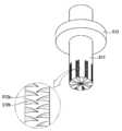
도 14는 본 발명의 일실시예에 따른 승강부의 단면 모습을 도시한 도면이다.14 is a view showing a cross-sectional view of a lifting unit according to an embodiment of the present invention.
도시된 바와 같이, 상기 승강부(600)는 회전기구(500)의 상부에 결합되며, 승강부(600)의 상부에는 카메라(120)가 결합된다. 승강부(600)에 의해 카메라(120)는 상하로 이동할 수 있다.As shown, the
상기 승강부(600)는 승강구동부(610), 승강하우징(680), 승강축(620), 다수의 승강지지바디(630), 지지바(640), 지지롤러(650), 승강스프링(660) 및 연결스프링(670)을 포함하여 이루어진다.The elevating
상기 승강구동부(610)는 회전기구(500)의 상부에 장착되며, 회전모터 등으로 구성되어 승강축(620)을 시계 방향 또는 반시계 방향으로 회전시켜 승강(상승 또는 하강)시킬 수 있다.The elevating
상기 승강하우징(680)은 내부가 비어있는 구형으로 형성되며, 승강구동부(610)의 상부에 결합된다. 승강하우징(680)의 내부에는 승강축(620), 승강지지바디(630), 지지바(640), 지지롤러(650), 승강스프링(660) 및 연결스프링(670) 등이 내장될 수 있다.The elevating
상기 승강축(620)은 승강구동부(610)의 상부에 연결되며, 시계 방향 또는 반시계 방향으로 회전될 수 있다. 승강하우징(680)의 하단에는 승강축(620)이 관통할 수 있도록 홀이 형성되며, 승강축(620)은 이러한 홀을 관통하여 승강구동부(610)와 연결된다. 또한, 승강하우징(680)의 상단에도 승강축(620)이 관통할 수 있도록 홀이 형성되며, 승강축(620)의 상단은 이러한 홀을 관통하여 카메라(120)와 연결된다.The elevating
상기 다수의 승강지지바디(630)는 승강축(620)의 외벽에 힌지 결합된다. 즉, 승강지지바디(630)는 승강축(620)에 결합된 부분을 기준으로 상하로 회전할 수 있으며, 이에 따라 지지바(640) 및 지지롤러(650)도 상하로 회전할 수 있다.The plurality of lifting
도시된 실시예에서 다수의 승강지지바디(630)는 4개로 구성되며, 승강지지바디(630)가 승강축(620)에 결합되는 부분을 기준으로 상측에 2개가 배치되고, 하측에 2개가 배치된다.In the illustrated embodiment, a plurality of lifting
상기 지지바(640)는 4개의 승강지지바디(630)의 각각의 말단에 인출 가능하도록 장착된다. 상기 지지바(640)가 인출 가능하므로 승강지지바디(630)의 단부로부터 지지바(640)의 단부까지의 전체 길이는 늘어나거나 줄어들 수 있다.The
상기 지지바(640)의 말단에는 각각 지지롤러(650)가 회전 가능하도록 장착된다. 상기 지지롤러(650)는 승강하우징(680)의 내측 벽에 구름 접촉되며, 지지바(640)를 지지한다.
상기 승강스프링(660)은 일측부가 승강지지바디(630)의 내부에 결합되고, 타측부가 지지바(640)에 결합되며, 지지바(640)에 탄성력을 제공한다. 상기 승강스프링(660)에 의해 지지바(640)는 승강하우징(680)의 내측 벽 방향으로 이동하려고 한다.One side of the
상기 연결스프링(670)은 4개의 승강지지바디(630)를 서로 연결하며, 다수의 승강지지바디(630)가 서로 지지될 수 있도록 한다. 상기 연결스프링(670)은 4개로 구성된다.The
구체적으로 승강지지바디(630)가 승강축(620)에 결합되는 부분을 기준으로 상측에 배치된 승강지지바디(630)를 서로 연결하는 연결스프링(670), 승강지지바디(630)가 승강축(620)에 결합되는 부분을 기준으로 하측에 배치된 승강지지바디(630)를 서로 연결하는 연결스프링(670), 승강지지바디(630)가 승강축(620)에 결합되는 부분을 기준으로 좌측에 배치된 승강지지바디(630)를 서로 연결하는 연결스프링(670) 및 승강지지바디(630)가 승강축(620)에 결합되는 부분을 기준으로 우측에 배치된 승강지지바디(630)를 서로 연결하는 연결스프링(670)으로 구성된다.Specifically, a
상기 승강구동부(610)의 작동시 승강지지바디(630), 지지바(640) 및 지지롤러(650)는 승강축(620)과 함께 회전되면서 승강되고, 지지롤러(650)는 승강하우징(680)의 내벽에 구름 접촉된다.When the
구체적으로 승강구동부(610)의 작동에 의해 승강축(620)이 상승되면, 승강지지바디(630)가 승강축(620)에 결합되는 부분을 기준으로 상측에 배치된 한 쌍의 승강지지바디(630)에 각각 결합된 지지바(640)는 승강스프링(660)의 탄성력을 이겨내고 승강지지바디(630) 내측으로 이동하고, 이에 따라 승강지지바디(630) 및 지지바(640)의 전체적인 길이는 줄어들게 된다.Specifically, when the elevating
또한, 승강구동부(610)의 작동에 의해 승강축(620)이 상승되면, 승강지지바디(630)가 승강축(620)에 결합되는 부분을 기준으로 하측에 배치된 한 쌍의 승강지지바디(630)에 각각 결합된 지지바(640)는 승강스프링(660)의 탄성력에 의해 승강지지바디(630) 외측으로 이동하고, 이에 따라 승강지지바디(630) 및 지지바(640)의 전체적인 길이는 늘어나게 된다.In addition, when the lifting
상기 승강구동부(610)의 작동에 의해 승강축(620)이 하강되면, 승강지지바디(630)가 승강축(620)에 결합되는 부분을 기준으로 상측에 배치된 한 쌍의 승강지지바디(630)에 각각 결합된 지지바(640)는 승강스프링(660)의 탄성력에 의해 승강지지바디(630) 외측으로 이동하고, 이에 따라 승강지지바디(630) 및 지지바(640)의 전체적인 길이는 늘어나게 된다.When the elevating
또한, 승강구동부(610)의 작동에 의해 승강축(620)이 하강되면, 승강지지바디(630)가 승강축(620)에 결합되는 부분을 기준으로 하측에 배치된 한 쌍의 승강지지바디(630)에 각각 결합된 지지바(640)는 승강스프링(660)의 탄성력을 이겨내고 승강지지바디(630) 내측으로 이동하고, 이에 따라 승강지지바디(630) 및 지지바(640)의 전체적인 길이는 줄어들게 된다.In addition, when the lifting
이와 같이, 본 발명은 승강구동부(610)의 작동에 따라 승강축(620)이 승강되어 승강지지바디(630) 및 지지바(640)의 길이가 유기적으로 가변될 수 있으므로 승강이 안정적으로 이루어질 수 있다는 장점이 있다.As described above, in the present invention, the elevating
또한, 승강축(620)의 승강 시 4개의 지지롤러(650)가 승강하우징(680)의 내벽에 구름 접촉되면서 승강축(620)을 지지하므로 안정적이며, 승강축(620)의 승강 중에 승강하우징(680)에 외부 충격이 가해져도 승강스프링(660)과 연결스프링(670)이 수축 또는 팽창하면서 충격을 흡수할 수 있으므로 안정적이다.In addition, when the lifting
이상에서 설명한 본 발명은 전술한 실시예 및 첨부된 도면에 의해 한정되는 것이 아니고, 본 발명의 기술적 사상을 벗어나지 않는 범위 내에서 여러 가지 치환, 변형 및 변경할 수 있다는 것이 본 발명이 속하는 기술분야에서 통상의 지식을 가진 자에게 있어 명백할 것이다.The present invention described above is not limited by the above-described embodiments and the accompanying drawings, and it is common in the technical field to which the present invention pertains that various substitutions, modifications and changes can be made without departing from the technical spirit of the present invention. It will be clear to those who have the knowledge of
10 : 인공위성20 : 주행거리장치30 : 기준좌표발신기
100 : 정보수집기110 : GPS수신기120 : 카메라
130 : 경사감지기140 : 저장장치150 : 입출력장치
160 : 고도계170 : 제어장치180 : 주행거리확인장치
200 : 완충기구210 : 완충로드211 : 완충체결부
212 : 완충원통부220 : 완충케이스230 : 완충스토퍼
240 : 완충연결부241 : 완충상하부242 : 완충좌우부
250 : 완충굴곡부251 : 제1굴곡부252 : 제2굴곡부
253 : 제3굴곡부254 : 제4굴곡부255 : 제5굴곡부
300 : 수평조절부310 : 높낮이케이스311 : 높낮이스프링
320 : 높낮이로드321 : 고정홈330 : 높낮이고정부
331 : 고정케이스331a : 제한홀332 : 고정로드
332a : 로드홈333 : 고정스프링334 : 고정제한부
335 : 제한판336 : 제한스프링337 : 제한이동부
338 : 제한로드400 : 착지대500 : 회전기구
510 : 수평회전부511 : 회전케이스511a : 회전걸림부
512 : 회전로드512a : 멈춤홈512b : 멈춤돌기
513 : 회전연장판514 : 회전볼520 : 회전제어부
521 : 제어케이스521a : 방지홈522 : 제어로드
523 : 멈춤부524 : 제어스프링525 : 방지부
526 : 제어이동부527 : 제어이동케이스528 : 제어손잡이
600 : 승강부610 : 승강구동부620 : 승강축
630 : 승강지지바디640 : 지지바650 : 지지롤러
660 : 승강스프링670 : 연결스프링680 : 승강하우징10: satellite 20: mileage device 30: reference coordinate transmitter
100: information collector 110: GPS receiver 120: camera
130: inclination detector 140: storage device 150: input/output device
160: altimeter 170: control device 180: mileage check device
200: buffer mechanism 210: buffer rod 211: buffer fastening part
212: buffer cylinder 220: buffer case 230: buffer stopper
240: buffer connection part 241: buffer upper and lower part 242: buffer left and right parts
250: buffer bent portion 251: first bent portion 252: second bent portion
253: third curved part 254: fourth curved part 255: fifth curved part
300: horizontal adjustment unit 310: height case 311: height spring
320: high and low rod 321: fixed groove 330: high and low fixed
331: fixed
332a: rod groove 333: fixing spring 334: fixing limiting part
335: limit plate 336: limit spring 337: limit movement part
338: limit rod 400: landing platform 500: rotating mechanism
510: horizontal rotating unit 511: rotating
512:
513: rotation extension plate 514: rotation ball 520: rotation control unit
521:
523: stop part 524: control spring 525: prevention part
526: control moving unit 527: control moving case 528: control handle
600: elevating unit 610: elevating drive unit 620: elevating shaft
630: lifting support body 640: support bar 650: support roller
660: elevating spring 670: connecting spring 680: elevating housing
Claims (1)
Translated fromKorean상기 정보수집기는,
차량에 내장되어 지표면의 굴곡 상태를 감지하는 경사감지기; 차량의 상부에 결합되는 수평조절부; 수평조절부의 상부에 결합되는 착지대; 착지대의 상부에 결합되는 완충기구; 완충기구의 상부에 결합되는 회전기구; 회전기구의 상부에 결합되는 승강부; 및 승강부의 상부에 결합되어 차량 주변을 촬영하는 카메라; 를 포함하고,
상기 경사감지기는,
차량에 고정되는 서포터; 서포터에 회전가능하게 결합되는 축대; 축대에 결합되어 서포터에 회동하도록 된 회동자; 축대의 외면에 밀착되도록 서포터에 결합되어서 축대의 회전을 정지시키는 브레이크; 를 포함하며,
상기 수평조절부는,
내부가 비어있는 원통형의 높낮이케이스; 높낮이케이스에 상하로 슬라이딩 가능하도록 수용되며 측면에 다수의 고정홈이 형성되는 높낮이로드; 및 높낮이케이스의 상단에 결합되며 다수의 고정홈으로 진입 가능한 고정로드를 구비하는 높낮이고정부; 를 포함하고,
상기 높낮이고정부는,
높낮이케이스의 상단에 결합되는 고정케이스; 고정케이스에 좌우로 슬라이딩 가능하도록 수용되며 단부가 다수의 고정홈에 진입할 수 있는 고정로드; 고정케이스의 내부에 수용되며 고정로드의 우단과 고정케이스의 내측 우단 사이를 연결하는 고정스프링; 및 고정케이스의 상부에 장착되며 고정로드의 움직임을 제한할 수 있는 고정제한부; 를 포함하며,
상기 고정제한부는,
고정케이스부의 상부면에 결합되는 제한판; 제한판의 상단에 결합되는 한 쌍의 제한스프링; 제한스프링의 하단에 연결되는 링 형태의 제한이동부; 및 제한이동부의 하단에 결합되는 제한로드; 를 포함하고,
상기 회전기구는,
승강부의 하단에 결합되어 승강부가 회전할 수 있도록 하는 수평회전부; 및 수평회전부의 하단에 장착되는 회전제어부; 를 포함하며,
상기 수평회전부는,
승강부의 하단에 결합되며 상단과 후단이 개방된 내부가 비어있는 원통형으로 형성되는 회전케이스; 회전케이스 내부에 수용되며 상단이 표척의 하단에 결합되고 하단이 회전케이스의 하단을 관통하여 회전제어부에 수용되는 회전로드; 회전로드의 측부에 돌출 연장되는 회전연장판; 회전케이스의 상단에 형성되며 회전연장판의 상부면과 접촉되는 회전걸림부; 및 회전연장판의 하부면과 회전케이스의 내측 하부면 사이에 배치되는 다수의 회전볼; 을 포함하고,
상기 회전제어부는,
회전케이스부의 하단에 결합되며 회전로드의 하단이 수용되는 제어케이스; 제어케이스의 내부에 수용되며 회전로드와 직교하는 방향으로 이동 가능한 제어로드; 제어로드의 일단에 결합되며 회전로드의 하부에 형성된 다수의 멈춤홈 중 어느 하나에 삽입될 수 있는 멈춤부; 멈춤부와 회전케이스의 내측면 사이에 결합되는 제어스프링; 제어로드의 타단에 결합되며 제어케이스의 측부에 형성된 방지홈의 삽입될 수 있는 방지부; 방지부의 일측에 결합되며 삼각형 형태의 단면을 가지는 제어이동부; 제어케이스의 측부에 결합되며 제어이동부가 좌우로 이동 가능하도록 삽입되는 제어이동케이스; 및 제어이동케이스의 상부에 상하로 이동 가능하도록 결합되며 하단이 제어이동부의 상부면에 접촉되는 제어손잡이; 를 포함하며,
상기 승강부는,
회전기구의 상부에 결합되는 승강구동부; 승강구동부의 상부에 결합되며 내부가 비어있는 구형의 승강하우징; 승강구동부에 연결되어 시계방향 또는 반시계방향으로 회전되고 상하로 승강하며 승강하우징의 내부에 배치되는 승강축; 승강축의 외벽에 힌지 결합되는 다수의 승강지지바디; 다수의 승강지지바디의 말단에 인출되게 장착되는 지지바; 지지바의 말단에 마련되어 승강하우징의 내벽에 지지되는 지지롤러; 일측부는 승강지지바디의 내부에 결합되고 타측부는 지지바에 결합되어 지지바를 탄성 지지하는 승강스프링; 및 다수의 승강지지바디를 서로 연결하여 다수의 승강지지바디가 지지될 수 있도록 하는 연결스프링; 을 포함하고,
상기 승강구동부의 작동시 승강 지지 바디, 지지바 및 지지롤러는 승강축과 함께 회전되면서 승강되고, 지지롤러는 승강하우징의 내벽에 구름 접촉되는 것을 특징으로 하는 수준 측량의 정밀도가 향상되고 지표면의 굴곡 상태를 측정할 수 있는 측지측량시스템.an information collector installed in a vehicle operating on site to collect information on the ground; and a reference coordinate transmitter installed on the ground surface having an inclination of 0 degrees and transmitting a reference signal. including,
The information collector,
an inclination sensor built into the vehicle to detect the curvature of the ground surface; a horizontal adjustment unit coupled to the upper portion of the vehicle; a landing platform coupled to the upper part of the horizontal adjustment unit; a buffer mechanism coupled to the upper portion of the landing platform; a rotation mechanism coupled to the upper portion of the buffer mechanism; Elevating unit coupled to the upper portion of the rotating mechanism; and a camera coupled to the upper part of the elevating part to photograph the surroundings of the vehicle; including,
The inclination sensor is
a supporter fixed to the vehicle; A shaft rotatably coupled to the supporter; a rotator coupled to the shaft and rotated to the supporter; a brake coupled to the supporter so as to be in close contact with the outer surface of the shaft to stop the rotation of the shaft; includes,
The horizontal adjustment unit,
Cylindrical height case with an empty interior; a height rod that is accommodated in the height case so as to be slidable up and down and has a plurality of fixing grooves formed on the side thereof; And it is coupled to the upper end of the height case, the height and lowering part having a fixing rod that can enter into a plurality of fixing grooves; including,
The height and the government,
Fixed case coupled to the upper part of the height case; a fixed rod which is accommodated in the fixed case to be slidable from side to side and whose ends can enter the plurality of fixing grooves; a fixing spring accommodated in the fixing case and connecting between the right end of the fixing rod and the inner right end of the fixing case; and a fixed limiting unit mounted on the upper portion of the fixed case and capable of restricting the movement of the fixed rod; includes,
The fixing limiting part,
a limiting plate coupled to the upper surface of the fixed case; a pair of limiting springs coupled to the top of the limiting plate; Ring-shaped limiting moving part connected to the lower end of the limiting spring; and a limiting rod coupled to the lower end of the limiting moving part; including,
The rotating mechanism is
a horizontal rotating unit coupled to the lower end of the elevating unit to allow the elevating unit to rotate; and a rotation control unit mounted on a lower end of the horizontal rotation unit; includes,
The horizontal rotation unit,
a rotating case coupled to the lower end of the elevating unit and formed in a cylindrical shape with an open top and a rear end; a rotating rod accommodated in the rotating case, the upper end being coupled to the lower end of the table chuck, and the lower end passing through the lower end of the rotating case and being accommodated in the rotating control unit; a rotation extension plate protruding from the side of the rotation rod; a rotation stopper formed on the upper end of the rotation case and in contact with the upper surface of the rotation extension plate; and a plurality of rotating balls disposed between the lower surface of the rotating extension plate and the inner lower surface of the rotating case; including,
The rotation control unit,
a control case coupled to the lower end of the rotating case unit and accommodating the lower end of the rotating rod; a control rod accommodated in the control case and movable in a direction perpendicular to the rotation rod; a stop portion coupled to one end of the control rod and capable of being inserted into any one of a plurality of stop grooves formed under the rotating rod; a control spring coupled between the stopper and the inner surface of the rotating case; a prevention portion coupled to the other end of the control rod and capable of being inserted into the prevention groove formed on the side of the control case; a control moving unit coupled to one side of the prevention unit and having a triangular cross section; a control moving case coupled to the side of the control case and inserted so that the control moving part can move left and right; and a control handle coupled to the upper part of the control moving case so as to be movable up and down, and the lower end of which is in contact with the upper surface of the control moving part. includes,
The lifting unit,
Elevating drive unit coupled to the upper portion of the rotating mechanism; a spherical elevating housing coupled to the upper part of the elevating drive and having an empty interior; an elevating shaft connected to the elevating drive unit, rotating clockwise or counterclockwise, elevating up and down, and disposed inside the elevating housing; A plurality of lifting support body hinged to the outer wall of the lifting shaft; a support bar mounted to be drawn out at the ends of the plurality of lifting support bodies; a support roller provided at the end of the support bar and supported on the inner wall of the elevating housing; an elevating spring having one side coupled to the inside of the elevating support body and the other side coupled to the support bar to elastically support the support bar; and a connection spring connecting the plurality of lifting support bodies to each other so that the plurality of lifting support bodies can be supported. including,
When the elevating drive unit is operated, the elevating support body, the support bar and the support roller are rotated together with the elevating shaft and elevate, and the support roller is in rolling contact with the inner wall of the elevating housing. A geodetic survey system capable of measuring conditions.
Priority Applications (1)
| Application Number | Priority Date | Filing Date | Title |
|---|---|---|---|
| KR1020210097046AKR102320522B1 (en) | 2021-07-23 | 2021-07-23 | Geodetic surveying system for improving precision of leveling and measuring curvature of surface |
Applications Claiming Priority (1)
| Application Number | Priority Date | Filing Date | Title |
|---|---|---|---|
| KR1020210097046AKR102320522B1 (en) | 2021-07-23 | 2021-07-23 | Geodetic surveying system for improving precision of leveling and measuring curvature of surface |
Publications (1)
| Publication Number | Publication Date |
|---|---|
| KR102320522B1true KR102320522B1 (en) | 2021-11-03 |
Family
ID=78505189
Family Applications (1)
| Application Number | Title | Priority Date | Filing Date |
|---|---|---|---|
| KR1020210097046AActiveKR102320522B1 (en) | 2021-07-23 | 2021-07-23 | Geodetic surveying system for improving precision of leveling and measuring curvature of surface |
Country Status (1)
| Country | Link |
|---|---|
| KR (1) | KR102320522B1 (en) |
Citations (3)
| Publication number | Priority date | Publication date | Assignee | Title |
|---|---|---|---|---|
| US5769370A (en)* | 1995-12-29 | 1998-06-23 | Javad Positioning, Llc | Knock-down satellite positioning system antenna supporting tripod |
| KR101121624B1 (en)* | 2011-10-17 | 2012-03-05 | 한국종합설계 주식회사 | Geodetic surveying system able to detailed measurement for a bent of the surface of the earth |
| KR101121626B1 (en)* | 2011-10-17 | 2012-03-05 | 한국종합설계 주식회사 | Geodetic surveying system measureing the geographical information |
- 2021
- 2021-07-23KRKR1020210097046Apatent/KR102320522B1/enactiveActive
Patent Citations (3)
| Publication number | Priority date | Publication date | Assignee | Title |
|---|---|---|---|---|
| US5769370A (en)* | 1995-12-29 | 1998-06-23 | Javad Positioning, Llc | Knock-down satellite positioning system antenna supporting tripod |
| KR101121624B1 (en)* | 2011-10-17 | 2012-03-05 | 한국종합설계 주식회사 | Geodetic surveying system able to detailed measurement for a bent of the surface of the earth |
| KR101121626B1 (en)* | 2011-10-17 | 2012-03-05 | 한국종합설계 주식회사 | Geodetic surveying system measureing the geographical information |
Similar Documents
| Publication | Publication Date | Title |
|---|---|---|
| KR101121626B1 (en) | Geodetic surveying system measureing the geographical information | |
| CN101063610B (en) | Automatic monitoring system for engineering project deformation | |
| CN100580373C (en) | Method and system for determining the spatial location of a hand-held measuring instrument | |
| KR102527650B1 (en) | Digital map production system for updating map image by reflecting terrain change of gis | |
| WO2014171573A1 (en) | Module for sensing active contact pressure of tire, and tire testing apparatus using same | |
| KR101240619B1 (en) | Gis realtime updating system for recording position of ground and under ground construction | |
| KR101705704B1 (en) | Digital map updating system | |
| KR102459673B1 (en) | Geodetic survey system for acquire geodetic survey data with minimal error value | |
| KR101126352B1 (en) | Geodetic surveying system making the numerical map having information of surface and height by the observation | |
| KR102357720B1 (en) | Geodetic surveying device for easily installing staff on ground | |
| US11703410B2 (en) | Pressire sensor including height determination with improved flexibility and reliability | |
| KR101821658B1 (en) | Measuring System and Method for Radious of Curvature of Underground Pipeline | |
| KR102336835B1 (en) | Geodetic surveying system for improving precision of surveying using national control point | |
| KR101126356B1 (en) | Geodetic surveying system updating the information by measuring the topography in gis | |
| KR102320522B1 (en) | Geodetic surveying system for improving precision of leveling and measuring curvature of surface | |
| US20240125597A1 (en) | In-the-field leveling calibration of a surveying instrument | |
| KR101125584B1 (en) | Device for determining the contour of a road surface | |
| KR102415009B1 (en) | Eodetic survey system for minimizing error value of measured data | |
| KR101121624B1 (en) | Geodetic surveying system able to detailed measurement for a bent of the surface of the earth | |
| KR102057072B1 (en) | A method and apparatus for measuring a slope change amount based on image recognition, which real-time measurement of a relative slope change amount in comparison with a point in time when installed in a structure and a facility | |
| Danisch et al. | Fusion of geodetic and MEMS sensors for integrated monitoring and analysis of deformations | |
| KR101561183B1 (en) | Based on the feature's GPS coordinates geodetic surveying and verification system | |
| KR101706099B1 (en) | Precision geodetic surveying system for measureing the geographical information | |
| KR101223244B1 (en) | The system for measuring coefficient of fluctuation in the surface of the earth | |
| KR102419377B1 (en) | transport protection device for geodetic survey |
Legal Events
| Date | Code | Title | Description |
|---|---|---|---|
| PA0109 | Patent application | Patent event code:PA01091R01D Comment text:Patent Application Patent event date:20210723 | |
| PA0201 | Request for examination | ||
| PA0302 | Request for accelerated examination | Patent event date:20210723 Patent event code:PA03022R01D Comment text:Request for Accelerated Examination | |
| E701 | Decision to grant or registration of patent right | ||
| PE0701 | Decision of registration | Patent event code:PE07011S01D Comment text:Decision to Grant Registration Patent event date:20211026 | |
| GRNT | Written decision to grant | ||
| PR0701 | Registration of establishment | Comment text:Registration of Establishment Patent event date:20211027 Patent event code:PR07011E01D | |
| PR1002 | Payment of registration fee | Payment date:20211028 End annual number:3 Start annual number:1 | |
| PG1601 | Publication of registration | ||
| PR1001 | Payment of annual fee | Payment date:20240729 Start annual number:4 End annual number:4 |