KR102317567B1 - Additive Manufacturing Using Powder Dispensing - Google Patents
Additive Manufacturing Using Powder DispensingDownload PDFInfo
- Publication number
- KR102317567B1 KR102317567B1KR1020207021959AKR20207021959AKR102317567B1KR 102317567 B1KR102317567 B1KR 102317567B1KR 1020207021959 AKR1020207021959 AKR 1020207021959AKR 20207021959 AKR20207021959 AKR 20207021959AKR 102317567 B1KR102317567 B1KR 102317567B1
- Authority
- KR
- South Korea
- Prior art keywords
- powder
- dispenser
- binder material
- platform
- layer
- Prior art date
- Legal status (The legal status is an assumption and is not a legal conclusion. Google has not performed a legal analysis and makes no representation as to the accuracy of the status listed.)
- Active
Links
- 239000000843powderSubstances0.000titleclaimsabstractdescription469
- 238000004519manufacturing processMethods0.000titleclaimsabstractdescription63
- 239000000654additiveSubstances0.000titleclaimsabstractdescription50
- 230000000996additive effectEffects0.000titleclaimsabstractdescription50
- 239000000463materialSubstances0.000claimsabstractdescription367
- 239000011230binding agentSubstances0.000claimsabstractdescription294
- 230000005855radiationEffects0.000claimsabstractdescription31
- 239000002245particleSubstances0.000claimsdescription110
- 239000003795chemical substances by applicationSubstances0.000claimsdescription45
- 238000000034methodMethods0.000claimsdescription38
- 239000000203mixtureSubstances0.000claimsdescription25
- 238000000280densificationMethods0.000claimsdescription19
- 239000007788liquidSubstances0.000claimsdescription18
- 239000000919ceramicSubstances0.000claimsdescription17
- 239000004033plasticSubstances0.000claimsdescription13
- 229920003023plasticPolymers0.000claimsdescription13
- 239000002184metalSubstances0.000claimsdescription8
- 229910052751metalInorganic materials0.000claimsdescription8
- 239000002923metal particleSubstances0.000claimsdescription7
- 238000012545processingMethods0.000claimsdescription7
- 238000005245sinteringMethods0.000claimsdescription6
- 239000007787solidSubstances0.000claimsdescription6
- 239000011159matrix materialSubstances0.000claimsdescription5
- 239000002105nanoparticleSubstances0.000claimsdescription5
- 238000000137annealingMethods0.000claimsdescription4
- 238000001513hot isostatic pressingMethods0.000claimsdescription3
- 239000002243precursorSubstances0.000claimsdescription3
- 230000002401inhibitory effectEffects0.000claims2
- 239000010410layerSubstances0.000description120
- 239000000126substanceSubstances0.000description14
- 238000012546transferMethods0.000description10
- 238000007639printingMethods0.000description8
- 230000008569processEffects0.000description8
- 238000011109contaminationMethods0.000description7
- 238000012805post-processingMethods0.000description7
- KFZMGEQAYNKOFK-UHFFFAOYSA-NIsopropanolChemical compoundCC(C)OKFZMGEQAYNKOFK-UHFFFAOYSA-N0.000description6
- 238000004590computer programMethods0.000description5
- 230000007246mechanismEffects0.000description5
- SECXISVLQFMRJM-UHFFFAOYSA-NN-MethylpyrrolidoneChemical compoundCN1CCCC1=OSECXISVLQFMRJM-UHFFFAOYSA-N0.000description4
- 238000009826distributionMethods0.000description4
- 239000012467final productSubstances0.000description4
- 239000012530fluidSubstances0.000description4
- 239000013528metallic particleSubstances0.000description4
- 239000000725suspensionSubstances0.000description4
- VYPSYNLAJGMNEJ-UHFFFAOYSA-NSilicium dioxideChemical compoundO=[Si]=OVYPSYNLAJGMNEJ-UHFFFAOYSA-N0.000description3
- 229910010293ceramic materialInorganic materials0.000description3
- 238000000151depositionMethods0.000description3
- 230000002452interceptive effectEffects0.000description3
- 150000002739metalsChemical class0.000description3
- 239000000047productSubstances0.000description3
- 239000007921spraySubstances0.000description3
- LFQSCWFLJHTTHZ-UHFFFAOYSA-NEthanolChemical compoundCCOLFQSCWFLJHTTHZ-UHFFFAOYSA-N0.000description2
- PXHVJJICTQNCMI-UHFFFAOYSA-NNickelChemical compound[Ni]PXHVJJICTQNCMI-UHFFFAOYSA-N0.000description2
- 239000000956alloySubstances0.000description2
- 229910045601alloyInorganic materials0.000description2
- QVGXLLKOCUKJST-UHFFFAOYSA-Natomic oxygenChemical compound[O]QVGXLLKOCUKJST-UHFFFAOYSA-N0.000description2
- 230000006399behaviorEffects0.000description2
- 238000011960computer-aided designMethods0.000description2
- 238000010276constructionMethods0.000description2
- 230000008021depositionEffects0.000description2
- 239000007789gasSubstances0.000description2
- 230000005484gravityEffects0.000description2
- 239000011261inert gasSubstances0.000description2
- 239000001995intermetallic alloySubstances0.000description2
- 230000006911nucleationEffects0.000description2
- 238000010899nucleationMethods0.000description2
- 229910052760oxygenInorganic materials0.000description2
- 239000001301oxygenSubstances0.000description2
- 239000002994raw materialSubstances0.000description2
- 238000000110selective laser sinteringMethods0.000description2
- 238000003892spreadingMethods0.000description2
- 230000007480spreadingEffects0.000description2
- 239000010936titaniumSubstances0.000description2
- 238000009736wettingMethods0.000description2
- 2380000101463D printingMethods0.000description1
- 229910000838Al alloyInorganic materials0.000description1
- VYZAMTAEIAYCRO-UHFFFAOYSA-NChromiumChemical compound[Cr]VYZAMTAEIAYCRO-UHFFFAOYSA-N0.000description1
- MYMOFIZGZYHOMD-UHFFFAOYSA-NDioxygenChemical compoundO=OMYMOFIZGZYHOMD-UHFFFAOYSA-N0.000description1
- 229910052581Si3N4Inorganic materials0.000description1
- RTAQQCXQSZGOHL-UHFFFAOYSA-NTitaniumChemical compound[Ti]RTAQQCXQSZGOHL-UHFFFAOYSA-N0.000description1
- 238000013019agitationMethods0.000description1
- 229910052782aluminiumInorganic materials0.000description1
- XAGFODPZIPBFFR-UHFFFAOYSA-NaluminiumChemical compound[Al]XAGFODPZIPBFFR-UHFFFAOYSA-N0.000description1
- PNEYBMLMFCGWSK-UHFFFAOYSA-Naluminium oxideInorganic materials[O-2].[O-2].[O-2].[Al+3].[Al+3]PNEYBMLMFCGWSK-UHFFFAOYSA-N0.000description1
- 238000000149argon plasma sinteringMethods0.000description1
- 230000015572biosynthetic processEffects0.000description1
- 239000000969carrierSubstances0.000description1
- -1ceriaChemical class0.000description1
- CETPSERCERDGAM-UHFFFAOYSA-Nceric oxideChemical compoundO=[Ce]=OCETPSERCERDGAM-UHFFFAOYSA-N0.000description1
- 229910000422cerium(IV) oxideInorganic materials0.000description1
- 229910052804chromiumInorganic materials0.000description1
- 239000011651chromiumSubstances0.000description1
- 238000004140cleaningMethods0.000description1
- 239000011248coating agentSubstances0.000description1
- 238000000576coating methodMethods0.000description1
- 239000010941cobaltSubstances0.000description1
- 229910017052cobaltInorganic materials0.000description1
- GUTLYIVDDKVIGB-UHFFFAOYSA-Ncobalt atomChemical compound[Co]GUTLYIVDDKVIGB-UHFFFAOYSA-N0.000description1
- 238000004891communicationMethods0.000description1
- 238000005056compactionMethods0.000description1
- 238000001816coolingMethods0.000description1
- PMHQVHHXPFUNSP-UHFFFAOYSA-Mcopper(1+);methylsulfanylmethane;bromideChemical compoundBr[Cu].CSCPMHQVHHXPFUNSP-UHFFFAOYSA-M0.000description1
- 238000005520cutting processMethods0.000description1
- 230000007547defectEffects0.000description1
- 230000001419dependent effectEffects0.000description1
- 238000010586diagramMethods0.000description1
- 229910001882dioxygenInorganic materials0.000description1
- 239000002019doping agentSubstances0.000description1
- 238000010894electron beam technologyMethods0.000description1
- 238000011049fillingMethods0.000description1
- 238000009472formulationMethods0.000description1
- 230000006870functionEffects0.000description1
- 230000004927fusionEffects0.000description1
- 239000003292glueSubstances0.000description1
- 229910001385heavy metalInorganic materials0.000description1
- 238000005286illuminationMethods0.000description1
- 238000007641inkjet printingMethods0.000description1
- 239000011229interlayerSubstances0.000description1
- 239000011344liquid materialSubstances0.000description1
- 238000003754machiningMethods0.000description1
- 238000002844meltingMethods0.000description1
- 230000008018meltingEffects0.000description1
- QSHDDOUJBYECFT-UHFFFAOYSA-NmercuryChemical compound[Hg]QSHDDOUJBYECFT-UHFFFAOYSA-N0.000description1
- 229910052753mercuryInorganic materials0.000description1
- 229910044991metal oxideInorganic materials0.000description1
- 150000004706metal oxidesChemical class0.000description1
- 238000012986modificationMethods0.000description1
- 230000004048modificationEffects0.000description1
- 229910052759nickelInorganic materials0.000description1
- 230000003287optical effectEffects0.000description1
- 239000004482other powderSubstances0.000description1
- 229920000642polymerPolymers0.000description1
- 239000012254powdered materialSubstances0.000description1
- 230000000644propagated effectEffects0.000description1
- 238000010926purgeMethods0.000description1
- 238000004064recyclingMethods0.000description1
- 230000000717retained effectEffects0.000description1
- 239000004576sandSubstances0.000description1
- HBMJWWWQQXIZIP-UHFFFAOYSA-Nsilicon carbideChemical compound[Si+]#[C-]HBMJWWWQQXIZIP-UHFFFAOYSA-N0.000description1
- 229910010271silicon carbideInorganic materials0.000description1
- 239000000377silicon dioxideSubstances0.000description1
- HQVNEWCFYHHQES-UHFFFAOYSA-Nsilicon nitrideChemical compoundN12[Si]34N5[Si]62N3[Si]51N64HQVNEWCFYHHQES-UHFFFAOYSA-N0.000description1
- 239000002002slurrySubstances0.000description1
- 238000005507sprayingMethods0.000description1
- 239000010935stainless steelSubstances0.000description1
- 229910001220stainless steelInorganic materials0.000description1
- 238000003860storageMethods0.000description1
- 229910052719titaniumInorganic materials0.000description1
- 229910052720vanadiumInorganic materials0.000description1
- LEONUFNNVUYDNQ-UHFFFAOYSA-Nvanadium atomChemical compound[V]LEONUFNNVUYDNQ-UHFFFAOYSA-N0.000description1
- 239000002699waste materialSubstances0.000description1
- 239000002023woodSubstances0.000description1
Images


Classifications
- B—PERFORMING OPERATIONS; TRANSPORTING
- B28—WORKING CEMENT, CLAY, OR STONE
- B28B—SHAPING CLAY OR OTHER CERAMIC COMPOSITIONS; SHAPING SLAG; SHAPING MIXTURES CONTAINING CEMENTITIOUS MATERIAL, e.g. PLASTER
- B28B7/00—Moulds; Cores; Mandrels
- B28B7/40—Moulds; Cores; Mandrels characterised by means for modifying the properties of the moulding material
- B28B7/46—Moulds; Cores; Mandrels characterised by means for modifying the properties of the moulding material for humidifying or dehumidifying
- B28B7/465—Applying setting liquid to dry mixtures
- B—PERFORMING OPERATIONS; TRANSPORTING
- B29—WORKING OF PLASTICS; WORKING OF SUBSTANCES IN A PLASTIC STATE IN GENERAL
- B29C—SHAPING OR JOINING OF PLASTICS; SHAPING OF MATERIAL IN A PLASTIC STATE, NOT OTHERWISE PROVIDED FOR; AFTER-TREATMENT OF THE SHAPED PRODUCTS, e.g. REPAIRING
- B29C64/00—Additive manufacturing, i.e. manufacturing of three-dimensional [3D] objects by additive deposition, additive agglomeration or additive layering, e.g. by 3D printing, stereolithography or selective laser sintering
- B29C64/20—Apparatus for additive manufacturing; Details thereof or accessories therefor
- B29C64/205—Means for applying layers
- B29C64/209—Heads; Nozzles
- B—PERFORMING OPERATIONS; TRANSPORTING
- B22—CASTING; POWDER METALLURGY
- B22F—WORKING METALLIC POWDER; MANUFACTURE OF ARTICLES FROM METALLIC POWDER; MAKING METALLIC POWDER; APPARATUS OR DEVICES SPECIALLY ADAPTED FOR METALLIC POWDER
- B22F1/00—Metallic powder; Treatment of metallic powder, e.g. to facilitate working or to improve properties
- B22F1/10—Metallic powder containing lubricating or binding agents; Metallic powder containing organic material
- B—PERFORMING OPERATIONS; TRANSPORTING
- B22—CASTING; POWDER METALLURGY
- B22F—WORKING METALLIC POWDER; MANUFACTURE OF ARTICLES FROM METALLIC POWDER; MAKING METALLIC POWDER; APPARATUS OR DEVICES SPECIALLY ADAPTED FOR METALLIC POWDER
- B22F10/00—Additive manufacturing of workpieces or articles from metallic powder
- B22F10/10—Formation of a green body
- B22F10/14—Formation of a green body by jetting of binder onto a bed of metal powder
- B—PERFORMING OPERATIONS; TRANSPORTING
- B22—CASTING; POWDER METALLURGY
- B22F—WORKING METALLIC POWDER; MANUFACTURE OF ARTICLES FROM METALLIC POWDER; MAKING METALLIC POWDER; APPARATUS OR DEVICES SPECIALLY ADAPTED FOR METALLIC POWDER
- B22F10/00—Additive manufacturing of workpieces or articles from metallic powder
- B22F10/40—Structures for supporting workpieces or articles during manufacture and removed afterwards
- B—PERFORMING OPERATIONS; TRANSPORTING
- B22—CASTING; POWDER METALLURGY
- B22F—WORKING METALLIC POWDER; MANUFACTURE OF ARTICLES FROM METALLIC POWDER; MAKING METALLIC POWDER; APPARATUS OR DEVICES SPECIALLY ADAPTED FOR METALLIC POWDER
- B22F12/00—Apparatus or devices specially adapted for additive manufacturing; Auxiliary means for additive manufacturing; Combinations of additive manufacturing apparatus or devices with other processing apparatus or devices
- B22F12/50—Means for feeding of material, e.g. heads
- B22F12/55—Two or more means for feeding material
- B—PERFORMING OPERATIONS; TRANSPORTING
- B22—CASTING; POWDER METALLURGY
- B22F—WORKING METALLIC POWDER; MANUFACTURE OF ARTICLES FROM METALLIC POWDER; MAKING METALLIC POWDER; APPARATUS OR DEVICES SPECIALLY ADAPTED FOR METALLIC POWDER
- B22F3/00—Manufacture of workpieces or articles from metallic powder characterised by the manner of compacting or sintering; Apparatus specially adapted therefor ; Presses and furnaces
- B22F3/10—Sintering only
- B—PERFORMING OPERATIONS; TRANSPORTING
- B22—CASTING; POWDER METALLURGY
- B22F—WORKING METALLIC POWDER; MANUFACTURE OF ARTICLES FROM METALLIC POWDER; MAKING METALLIC POWDER; APPARATUS OR DEVICES SPECIALLY ADAPTED FOR METALLIC POWDER
- B22F3/00—Manufacture of workpieces or articles from metallic powder characterised by the manner of compacting or sintering; Apparatus specially adapted therefor ; Presses and furnaces
- B22F3/12—Both compacting and sintering
- B22F3/14—Both compacting and sintering simultaneously
- B22F3/15—Hot isostatic pressing
- B—PERFORMING OPERATIONS; TRANSPORTING
- B28—WORKING CEMENT, CLAY, OR STONE
- B28B—SHAPING CLAY OR OTHER CERAMIC COMPOSITIONS; SHAPING SLAG; SHAPING MIXTURES CONTAINING CEMENTITIOUS MATERIAL, e.g. PLASTER
- B28B1/00—Producing shaped prefabricated articles from the material
- B28B1/001—Rapid manufacturing of 3D objects by additive depositing, agglomerating or laminating of material
- B—PERFORMING OPERATIONS; TRANSPORTING
- B28—WORKING CEMENT, CLAY, OR STONE
- B28B—SHAPING CLAY OR OTHER CERAMIC COMPOSITIONS; SHAPING SLAG; SHAPING MIXTURES CONTAINING CEMENTITIOUS MATERIAL, e.g. PLASTER
- B28B11/00—Apparatus or processes for treating or working the shaped or preshaped articles
- B28B11/24—Apparatus or processes for treating or working the shaped or preshaped articles for curing, setting or hardening
- B28B11/243—Setting, e.g. drying, dehydrating or firing ceramic articles
- B—PERFORMING OPERATIONS; TRANSPORTING
- B29—WORKING OF PLASTICS; WORKING OF SUBSTANCES IN A PLASTIC STATE IN GENERAL
- B29C—SHAPING OR JOINING OF PLASTICS; SHAPING OF MATERIAL IN A PLASTIC STATE, NOT OTHERWISE PROVIDED FOR; AFTER-TREATMENT OF THE SHAPED PRODUCTS, e.g. REPAIRING
- B29C64/00—Additive manufacturing, i.e. manufacturing of three-dimensional [3D] objects by additive deposition, additive agglomeration or additive layering, e.g. by 3D printing, stereolithography or selective laser sintering
- B29C64/10—Processes of additive manufacturing
- B29C64/141—Processes of additive manufacturing using only solid materials
- B29C64/153—Processes of additive manufacturing using only solid materials using layers of powder being selectively joined, e.g. by selective laser sintering or melting
- B—PERFORMING OPERATIONS; TRANSPORTING
- B29—WORKING OF PLASTICS; WORKING OF SUBSTANCES IN A PLASTIC STATE IN GENERAL
- B29C—SHAPING OR JOINING OF PLASTICS; SHAPING OF MATERIAL IN A PLASTIC STATE, NOT OTHERWISE PROVIDED FOR; AFTER-TREATMENT OF THE SHAPED PRODUCTS, e.g. REPAIRING
- B29C64/00—Additive manufacturing, i.e. manufacturing of three-dimensional [3D] objects by additive deposition, additive agglomeration or additive layering, e.g. by 3D printing, stereolithography or selective laser sintering
- B29C64/10—Processes of additive manufacturing
- B29C64/165—Processes of additive manufacturing using a combination of solid and fluid materials, e.g. a powder selectively bound by a liquid binder, catalyst, inhibitor or energy absorber
- B—PERFORMING OPERATIONS; TRANSPORTING
- B29—WORKING OF PLASTICS; WORKING OF SUBSTANCES IN A PLASTIC STATE IN GENERAL
- B29C—SHAPING OR JOINING OF PLASTICS; SHAPING OF MATERIAL IN A PLASTIC STATE, NOT OTHERWISE PROVIDED FOR; AFTER-TREATMENT OF THE SHAPED PRODUCTS, e.g. REPAIRING
- B29C64/00—Additive manufacturing, i.e. manufacturing of three-dimensional [3D] objects by additive deposition, additive agglomeration or additive layering, e.g. by 3D printing, stereolithography or selective laser sintering
- B29C64/20—Apparatus for additive manufacturing; Details thereof or accessories therefor
- B29C64/264—Arrangements for irradiation
- B—PERFORMING OPERATIONS; TRANSPORTING
- B29—WORKING OF PLASTICS; WORKING OF SUBSTANCES IN A PLASTIC STATE IN GENERAL
- B29C—SHAPING OR JOINING OF PLASTICS; SHAPING OF MATERIAL IN A PLASTIC STATE, NOT OTHERWISE PROVIDED FOR; AFTER-TREATMENT OF THE SHAPED PRODUCTS, e.g. REPAIRING
- B29C64/00—Additive manufacturing, i.e. manufacturing of three-dimensional [3D] objects by additive deposition, additive agglomeration or additive layering, e.g. by 3D printing, stereolithography or selective laser sintering
- B29C64/30—Auxiliary operations or equipment
- B29C64/307—Handling of material to be used in additive manufacturing
- B29C64/321—Feeding
- B29C64/336—Feeding of two or more materials
- B—PERFORMING OPERATIONS; TRANSPORTING
- B29—WORKING OF PLASTICS; WORKING OF SUBSTANCES IN A PLASTIC STATE IN GENERAL
- B29C—SHAPING OR JOINING OF PLASTICS; SHAPING OF MATERIAL IN A PLASTIC STATE, NOT OTHERWISE PROVIDED FOR; AFTER-TREATMENT OF THE SHAPED PRODUCTS, e.g. REPAIRING
- B29C64/00—Additive manufacturing, i.e. manufacturing of three-dimensional [3D] objects by additive deposition, additive agglomeration or additive layering, e.g. by 3D printing, stereolithography or selective laser sintering
- B29C64/30—Auxiliary operations or equipment
- B29C64/386—Data acquisition or data processing for additive manufacturing
- B29C64/393—Data acquisition or data processing for additive manufacturing for controlling or regulating additive manufacturing processes
- B—PERFORMING OPERATIONS; TRANSPORTING
- B33—ADDITIVE MANUFACTURING TECHNOLOGY
- B33Y—ADDITIVE MANUFACTURING, i.e. MANUFACTURING OF THREE-DIMENSIONAL [3-D] OBJECTS BY ADDITIVE DEPOSITION, ADDITIVE AGGLOMERATION OR ADDITIVE LAYERING, e.g. BY 3-D PRINTING, STEREOLITHOGRAPHY OR SELECTIVE LASER SINTERING
- B33Y10/00—Processes of additive manufacturing
- B—PERFORMING OPERATIONS; TRANSPORTING
- B33—ADDITIVE MANUFACTURING TECHNOLOGY
- B33Y—ADDITIVE MANUFACTURING, i.e. MANUFACTURING OF THREE-DIMENSIONAL [3-D] OBJECTS BY ADDITIVE DEPOSITION, ADDITIVE AGGLOMERATION OR ADDITIVE LAYERING, e.g. BY 3-D PRINTING, STEREOLITHOGRAPHY OR SELECTIVE LASER SINTERING
- B33Y30/00—Apparatus for additive manufacturing; Details thereof or accessories therefor
- B—PERFORMING OPERATIONS; TRANSPORTING
- B33—ADDITIVE MANUFACTURING TECHNOLOGY
- B33Y—ADDITIVE MANUFACTURING, i.e. MANUFACTURING OF THREE-DIMENSIONAL [3-D] OBJECTS BY ADDITIVE DEPOSITION, ADDITIVE AGGLOMERATION OR ADDITIVE LAYERING, e.g. BY 3-D PRINTING, STEREOLITHOGRAPHY OR SELECTIVE LASER SINTERING
- B33Y40/00—Auxiliary operations or equipment, e.g. for material handling
- B—PERFORMING OPERATIONS; TRANSPORTING
- B33—ADDITIVE MANUFACTURING TECHNOLOGY
- B33Y—ADDITIVE MANUFACTURING, i.e. MANUFACTURING OF THREE-DIMENSIONAL [3-D] OBJECTS BY ADDITIVE DEPOSITION, ADDITIVE AGGLOMERATION OR ADDITIVE LAYERING, e.g. BY 3-D PRINTING, STEREOLITHOGRAPHY OR SELECTIVE LASER SINTERING
- B33Y70/00—Materials specially adapted for additive manufacturing
- C—CHEMISTRY; METALLURGY
- C04—CEMENTS; CONCRETE; ARTIFICIAL STONE; CERAMICS; REFRACTORIES
- C04B—LIME, MAGNESIA; SLAG; CEMENTS; COMPOSITIONS THEREOF, e.g. MORTARS, CONCRETE OR LIKE BUILDING MATERIALS; ARTIFICIAL STONE; CERAMICS; REFRACTORIES; TREATMENT OF NATURAL STONE
- C04B35/00—Shaped ceramic products characterised by their composition; Ceramics compositions; Processing powders of inorganic compounds preparatory to the manufacturing of ceramic products
- C04B35/01—Shaped ceramic products characterised by their composition; Ceramics compositions; Processing powders of inorganic compounds preparatory to the manufacturing of ceramic products based on oxide ceramics
- C04B35/10—Shaped ceramic products characterised by their composition; Ceramics compositions; Processing powders of inorganic compounds preparatory to the manufacturing of ceramic products based on oxide ceramics based on aluminium oxide
- C04B35/111—Fine ceramics
- C—CHEMISTRY; METALLURGY
- C04—CEMENTS; CONCRETE; ARTIFICIAL STONE; CERAMICS; REFRACTORIES
- C04B—LIME, MAGNESIA; SLAG; CEMENTS; COMPOSITIONS THEREOF, e.g. MORTARS, CONCRETE OR LIKE BUILDING MATERIALS; ARTIFICIAL STONE; CERAMICS; REFRACTORIES; TREATMENT OF NATURAL STONE
- C04B35/00—Shaped ceramic products characterised by their composition; Ceramics compositions; Processing powders of inorganic compounds preparatory to the manufacturing of ceramic products
- C04B35/01—Shaped ceramic products characterised by their composition; Ceramics compositions; Processing powders of inorganic compounds preparatory to the manufacturing of ceramic products based on oxide ceramics
- C04B35/14—Shaped ceramic products characterised by their composition; Ceramics compositions; Processing powders of inorganic compounds preparatory to the manufacturing of ceramic products based on oxide ceramics based on silica
- C—CHEMISTRY; METALLURGY
- C04—CEMENTS; CONCRETE; ARTIFICIAL STONE; CERAMICS; REFRACTORIES
- C04B—LIME, MAGNESIA; SLAG; CEMENTS; COMPOSITIONS THEREOF, e.g. MORTARS, CONCRETE OR LIKE BUILDING MATERIALS; ARTIFICIAL STONE; CERAMICS; REFRACTORIES; TREATMENT OF NATURAL STONE
- C04B35/00—Shaped ceramic products characterised by their composition; Ceramics compositions; Processing powders of inorganic compounds preparatory to the manufacturing of ceramic products
- C04B35/50—Shaped ceramic products characterised by their composition; Ceramics compositions; Processing powders of inorganic compounds preparatory to the manufacturing of ceramic products based on rare-earth compounds
- C—CHEMISTRY; METALLURGY
- C04—CEMENTS; CONCRETE; ARTIFICIAL STONE; CERAMICS; REFRACTORIES
- C04B—LIME, MAGNESIA; SLAG; CEMENTS; COMPOSITIONS THEREOF, e.g. MORTARS, CONCRETE OR LIKE BUILDING MATERIALS; ARTIFICIAL STONE; CERAMICS; REFRACTORIES; TREATMENT OF NATURAL STONE
- C04B35/00—Shaped ceramic products characterised by their composition; Ceramics compositions; Processing powders of inorganic compounds preparatory to the manufacturing of ceramic products
- C04B35/515—Shaped ceramic products characterised by their composition; Ceramics compositions; Processing powders of inorganic compounds preparatory to the manufacturing of ceramic products based on non-oxide ceramics
- C04B35/58—Shaped ceramic products characterised by their composition; Ceramics compositions; Processing powders of inorganic compounds preparatory to the manufacturing of ceramic products based on non-oxide ceramics based on borides, nitrides, i.e. nitrides, oxynitrides, carbonitrides or oxycarbonitrides or silicides
- C04B35/581—Shaped ceramic products characterised by their composition; Ceramics compositions; Processing powders of inorganic compounds preparatory to the manufacturing of ceramic products based on non-oxide ceramics based on borides, nitrides, i.e. nitrides, oxynitrides, carbonitrides or oxycarbonitrides or silicides based on aluminium nitride
- C—CHEMISTRY; METALLURGY
- C04—CEMENTS; CONCRETE; ARTIFICIAL STONE; CERAMICS; REFRACTORIES
- C04B—LIME, MAGNESIA; SLAG; CEMENTS; COMPOSITIONS THEREOF, e.g. MORTARS, CONCRETE OR LIKE BUILDING MATERIALS; ARTIFICIAL STONE; CERAMICS; REFRACTORIES; TREATMENT OF NATURAL STONE
- C04B35/00—Shaped ceramic products characterised by their composition; Ceramics compositions; Processing powders of inorganic compounds preparatory to the manufacturing of ceramic products
- C04B35/515—Shaped ceramic products characterised by their composition; Ceramics compositions; Processing powders of inorganic compounds preparatory to the manufacturing of ceramic products based on non-oxide ceramics
- C04B35/58—Shaped ceramic products characterised by their composition; Ceramics compositions; Processing powders of inorganic compounds preparatory to the manufacturing of ceramic products based on non-oxide ceramics based on borides, nitrides, i.e. nitrides, oxynitrides, carbonitrides or oxycarbonitrides or silicides
- C04B35/584—Shaped ceramic products characterised by their composition; Ceramics compositions; Processing powders of inorganic compounds preparatory to the manufacturing of ceramic products based on non-oxide ceramics based on borides, nitrides, i.e. nitrides, oxynitrides, carbonitrides or oxycarbonitrides or silicides based on silicon nitride
- C—CHEMISTRY; METALLURGY
- C04—CEMENTS; CONCRETE; ARTIFICIAL STONE; CERAMICS; REFRACTORIES
- C04B—LIME, MAGNESIA; SLAG; CEMENTS; COMPOSITIONS THEREOF, e.g. MORTARS, CONCRETE OR LIKE BUILDING MATERIALS; ARTIFICIAL STONE; CERAMICS; REFRACTORIES; TREATMENT OF NATURAL STONE
- C04B35/00—Shaped ceramic products characterised by their composition; Ceramics compositions; Processing powders of inorganic compounds preparatory to the manufacturing of ceramic products
- C04B35/622—Forming processes; Processing powders of inorganic compounds preparatory to the manufacturing of ceramic products
- C04B35/624—Sol-gel processing
- C—CHEMISTRY; METALLURGY
- C04—CEMENTS; CONCRETE; ARTIFICIAL STONE; CERAMICS; REFRACTORIES
- C04B—LIME, MAGNESIA; SLAG; CEMENTS; COMPOSITIONS THEREOF, e.g. MORTARS, CONCRETE OR LIKE BUILDING MATERIALS; ARTIFICIAL STONE; CERAMICS; REFRACTORIES; TREATMENT OF NATURAL STONE
- C04B35/00—Shaped ceramic products characterised by their composition; Ceramics compositions; Processing powders of inorganic compounds preparatory to the manufacturing of ceramic products
- C04B35/622—Forming processes; Processing powders of inorganic compounds preparatory to the manufacturing of ceramic products
- C04B35/626—Preparing or treating the powders individually or as batches ; preparing or treating macroscopic reinforcing agents for ceramic products, e.g. fibres; mechanical aspects section B
- C04B35/62605—Treating the starting powders individually or as mixtures
- C04B35/62625—Wet mixtures
- C04B35/6264—Mixing media, e.g. organic solvents
- C—CHEMISTRY; METALLURGY
- C04—CEMENTS; CONCRETE; ARTIFICIAL STONE; CERAMICS; REFRACTORIES
- C04B—LIME, MAGNESIA; SLAG; CEMENTS; COMPOSITIONS THEREOF, e.g. MORTARS, CONCRETE OR LIKE BUILDING MATERIALS; ARTIFICIAL STONE; CERAMICS; REFRACTORIES; TREATMENT OF NATURAL STONE
- C04B35/00—Shaped ceramic products characterised by their composition; Ceramics compositions; Processing powders of inorganic compounds preparatory to the manufacturing of ceramic products
- C04B35/622—Forming processes; Processing powders of inorganic compounds preparatory to the manufacturing of ceramic products
- C04B35/626—Preparing or treating the powders individually or as batches ; preparing or treating macroscopic reinforcing agents for ceramic products, e.g. fibres; mechanical aspects section B
- C04B35/62605—Treating the starting powders individually or as mixtures
- C04B35/6269—Curing of mixtures
- C—CHEMISTRY; METALLURGY
- C04—CEMENTS; CONCRETE; ARTIFICIAL STONE; CERAMICS; REFRACTORIES
- C04B—LIME, MAGNESIA; SLAG; CEMENTS; COMPOSITIONS THEREOF, e.g. MORTARS, CONCRETE OR LIKE BUILDING MATERIALS; ARTIFICIAL STONE; CERAMICS; REFRACTORIES; TREATMENT OF NATURAL STONE
- C04B35/00—Shaped ceramic products characterised by their composition; Ceramics compositions; Processing powders of inorganic compounds preparatory to the manufacturing of ceramic products
- C04B35/622—Forming processes; Processing powders of inorganic compounds preparatory to the manufacturing of ceramic products
- C04B35/626—Preparing or treating the powders individually or as batches ; preparing or treating macroscopic reinforcing agents for ceramic products, e.g. fibres; mechanical aspects section B
- C04B35/63—Preparing or treating the powders individually or as batches ; preparing or treating macroscopic reinforcing agents for ceramic products, e.g. fibres; mechanical aspects section B using additives specially adapted for forming the products, e.g.. binder binders
- C04B35/632—Organic additives
- C04B35/634—Polymers
- C—CHEMISTRY; METALLURGY
- C04—CEMENTS; CONCRETE; ARTIFICIAL STONE; CERAMICS; REFRACTORIES
- C04B—LIME, MAGNESIA; SLAG; CEMENTS; COMPOSITIONS THEREOF, e.g. MORTARS, CONCRETE OR LIKE BUILDING MATERIALS; ARTIFICIAL STONE; CERAMICS; REFRACTORIES; TREATMENT OF NATURAL STONE
- C04B35/00—Shaped ceramic products characterised by their composition; Ceramics compositions; Processing powders of inorganic compounds preparatory to the manufacturing of ceramic products
- C04B35/622—Forming processes; Processing powders of inorganic compounds preparatory to the manufacturing of ceramic products
- C04B35/64—Burning or sintering processes
- B—PERFORMING OPERATIONS; TRANSPORTING
- B22—CASTING; POWDER METALLURGY
- B22F—WORKING METALLIC POWDER; MANUFACTURE OF ARTICLES FROM METALLIC POWDER; MAKING METALLIC POWDER; APPARATUS OR DEVICES SPECIALLY ADAPTED FOR METALLIC POWDER
- B22F10/00—Additive manufacturing of workpieces or articles from metallic powder
- B22F10/30—Process control
- B22F10/32—Process control of the atmosphere, e.g. composition or pressure in a building chamber
- B—PERFORMING OPERATIONS; TRANSPORTING
- B22—CASTING; POWDER METALLURGY
- B22F—WORKING METALLIC POWDER; MANUFACTURE OF ARTICLES FROM METALLIC POWDER; MAKING METALLIC POWDER; APPARATUS OR DEVICES SPECIALLY ADAPTED FOR METALLIC POWDER
- B22F12/00—Apparatus or devices specially adapted for additive manufacturing; Auxiliary means for additive manufacturing; Combinations of additive manufacturing apparatus or devices with other processing apparatus or devices
- B22F12/40—Radiation means
- B22F12/41—Radiation means characterised by the type, e.g. laser or electron beam
- B22F12/42—Light-emitting diodes [LED]
- B—PERFORMING OPERATIONS; TRANSPORTING
- B22—CASTING; POWDER METALLURGY
- B22F—WORKING METALLIC POWDER; MANUFACTURE OF ARTICLES FROM METALLIC POWDER; MAKING METALLIC POWDER; APPARATUS OR DEVICES SPECIALLY ADAPTED FOR METALLIC POWDER
- B22F12/00—Apparatus or devices specially adapted for additive manufacturing; Auxiliary means for additive manufacturing; Combinations of additive manufacturing apparatus or devices with other processing apparatus or devices
- B22F12/50—Means for feeding of material, e.g. heads
- B22F12/53—Nozzles
- B—PERFORMING OPERATIONS; TRANSPORTING
- B22—CASTING; POWDER METALLURGY
- B22F—WORKING METALLIC POWDER; MANUFACTURE OF ARTICLES FROM METALLIC POWDER; MAKING METALLIC POWDER; APPARATUS OR DEVICES SPECIALLY ADAPTED FOR METALLIC POWDER
- B22F12/00—Apparatus or devices specially adapted for additive manufacturing; Auxiliary means for additive manufacturing; Combinations of additive manufacturing apparatus or devices with other processing apparatus or devices
- B22F12/90—Means for process control, e.g. cameras or sensors
- B—PERFORMING OPERATIONS; TRANSPORTING
- B22—CASTING; POWDER METALLURGY
- B22F—WORKING METALLIC POWDER; MANUFACTURE OF ARTICLES FROM METALLIC POWDER; MAKING METALLIC POWDER; APPARATUS OR DEVICES SPECIALLY ADAPTED FOR METALLIC POWDER
- B22F3/00—Manufacture of workpieces or articles from metallic powder characterised by the manner of compacting or sintering; Apparatus specially adapted therefor ; Presses and furnaces
- B22F3/10—Sintering only
- B22F3/1017—Multiple heating or additional steps
- B22F3/1021—Removal of binder or filler
- B—PERFORMING OPERATIONS; TRANSPORTING
- B33—ADDITIVE MANUFACTURING TECHNOLOGY
- B33Y—ADDITIVE MANUFACTURING, i.e. MANUFACTURING OF THREE-DIMENSIONAL [3-D] OBJECTS BY ADDITIVE DEPOSITION, ADDITIVE AGGLOMERATION OR ADDITIVE LAYERING, e.g. BY 3-D PRINTING, STEREOLITHOGRAPHY OR SELECTIVE LASER SINTERING
- B33Y50/00—Data acquisition or data processing for additive manufacturing
- B33Y50/02—Data acquisition or data processing for additive manufacturing for controlling or regulating additive manufacturing processes
- C—CHEMISTRY; METALLURGY
- C04—CEMENTS; CONCRETE; ARTIFICIAL STONE; CERAMICS; REFRACTORIES
- C04B—LIME, MAGNESIA; SLAG; CEMENTS; COMPOSITIONS THEREOF, e.g. MORTARS, CONCRETE OR LIKE BUILDING MATERIALS; ARTIFICIAL STONE; CERAMICS; REFRACTORIES; TREATMENT OF NATURAL STONE
- C04B2235/00—Aspects relating to ceramic starting mixtures or sintered ceramic products
- C04B2235/02—Composition of constituents of the starting material or of secondary phases of the final product
- C04B2235/50—Constituents or additives of the starting mixture chosen for their shape or used because of their shape or their physical appearance
- C04B2235/54—Particle size related information
- C04B2235/5418—Particle size related information expressed by the size of the particles or aggregates thereof
- C04B2235/5436—Particle size related information expressed by the size of the particles or aggregates thereof micrometer sized, i.e. from 1 to 100 micron
- C—CHEMISTRY; METALLURGY
- C04—CEMENTS; CONCRETE; ARTIFICIAL STONE; CERAMICS; REFRACTORIES
- C04B—LIME, MAGNESIA; SLAG; CEMENTS; COMPOSITIONS THEREOF, e.g. MORTARS, CONCRETE OR LIKE BUILDING MATERIALS; ARTIFICIAL STONE; CERAMICS; REFRACTORIES; TREATMENT OF NATURAL STONE
- C04B2235/00—Aspects relating to ceramic starting mixtures or sintered ceramic products
- C04B2235/02—Composition of constituents of the starting material or of secondary phases of the final product
- C04B2235/50—Constituents or additives of the starting mixture chosen for their shape or used because of their shape or their physical appearance
- C04B2235/54—Particle size related information
- C04B2235/5418—Particle size related information expressed by the size of the particles or aggregates thereof
- C04B2235/5454—Particle size related information expressed by the size of the particles or aggregates thereof nanometer sized, i.e. below 100 nm
- C—CHEMISTRY; METALLURGY
- C04—CEMENTS; CONCRETE; ARTIFICIAL STONE; CERAMICS; REFRACTORIES
- C04B—LIME, MAGNESIA; SLAG; CEMENTS; COMPOSITIONS THEREOF, e.g. MORTARS, CONCRETE OR LIKE BUILDING MATERIALS; ARTIFICIAL STONE; CERAMICS; REFRACTORIES; TREATMENT OF NATURAL STONE
- C04B2235/00—Aspects relating to ceramic starting mixtures or sintered ceramic products
- C04B2235/02—Composition of constituents of the starting material or of secondary phases of the final product
- C04B2235/50—Constituents or additives of the starting mixture chosen for their shape or used because of their shape or their physical appearance
- C04B2235/54—Particle size related information
- C04B2235/5463—Particle size distributions
- C04B2235/5472—Bimodal, multi-modal or multi-fraction
- C—CHEMISTRY; METALLURGY
- C04—CEMENTS; CONCRETE; ARTIFICIAL STONE; CERAMICS; REFRACTORIES
- C04B—LIME, MAGNESIA; SLAG; CEMENTS; COMPOSITIONS THEREOF, e.g. MORTARS, CONCRETE OR LIKE BUILDING MATERIALS; ARTIFICIAL STONE; CERAMICS; REFRACTORIES; TREATMENT OF NATURAL STONE
- C04B2235/00—Aspects relating to ceramic starting mixtures or sintered ceramic products
- C04B2235/60—Aspects relating to the preparation, properties or mechanical treatment of green bodies or pre-forms
- C04B2235/602—Making the green bodies or pre-forms by moulding
- C04B2235/6026—Computer aided shaping, e.g. rapid prototyping
- C—CHEMISTRY; METALLURGY
- C04—CEMENTS; CONCRETE; ARTIFICIAL STONE; CERAMICS; REFRACTORIES
- C04B—LIME, MAGNESIA; SLAG; CEMENTS; COMPOSITIONS THEREOF, e.g. MORTARS, CONCRETE OR LIKE BUILDING MATERIALS; ARTIFICIAL STONE; CERAMICS; REFRACTORIES; TREATMENT OF NATURAL STONE
- C04B2235/00—Aspects relating to ceramic starting mixtures or sintered ceramic products
- C04B2235/65—Aspects relating to heat treatments of ceramic bodies such as green ceramics or pre-sintered ceramics, e.g. burning, sintering or melting processes
- C04B2235/66—Specific sintering techniques, e.g. centrifugal sintering
- C04B2235/665—Local sintering, e.g. laser sintering
- Y—GENERAL TAGGING OF NEW TECHNOLOGICAL DEVELOPMENTS; GENERAL TAGGING OF CROSS-SECTIONAL TECHNOLOGIES SPANNING OVER SEVERAL SECTIONS OF THE IPC; TECHNICAL SUBJECTS COVERED BY FORMER USPC CROSS-REFERENCE ART COLLECTIONS [XRACs] AND DIGESTS
- Y02—TECHNOLOGIES OR APPLICATIONS FOR MITIGATION OR ADAPTATION AGAINST CLIMATE CHANGE
- Y02P—CLIMATE CHANGE MITIGATION TECHNOLOGIES IN THE PRODUCTION OR PROCESSING OF GOODS
- Y02P10/00—Technologies related to metal processing
- Y02P10/25—Process efficiency
Landscapes
- Engineering & Computer Science (AREA)
- Chemical & Material Sciences (AREA)
- Manufacturing & Machinery (AREA)
- Materials Engineering (AREA)
- Ceramic Engineering (AREA)
- Structural Engineering (AREA)
- Mechanical Engineering (AREA)
- Organic Chemistry (AREA)
- Physics & Mathematics (AREA)
- Optics & Photonics (AREA)
- Inorganic Chemistry (AREA)
- Dispersion Chemistry (AREA)
- Health & Medical Sciences (AREA)
- Toxicology (AREA)
- Producing Shaped Articles From Materials (AREA)
- Powder Metallurgy (AREA)
Abstract
Translated fromKoreanDescription
Translated fromKorean본 명세서는, 적층 제조 장치들을 위한, 예컨대, 그린 부품(green part)의 제조를 위한 분말 분배기 시스템들, 결합제 분배 시스템들, 및 에너지 전달 시스템들에 관한 것이다.TECHNICAL FIELD This specification relates to powder dispenser systems, binder dispensing systems, and energy delivery systems for additive manufacturing devices, such as for the production of green parts.
입체 임의형상 제조 또는 3D 프린팅으로 또한 알려져 있는 적층 제조(AM)는 원재료(예컨대, 분말들, 액체들, 현탁액들, 또는 용융된 고체들)를 2차원 층들로 연속적으로 분배하여 3차원 물체들이 구축되는 제조 프로세스를 지칭한다. 대조적으로, 종래의 기계가공 기법들은, 원자재(예컨대, 목재, 플라스틱, 또는 금속의 덩어리)로부터 물품들이 절단되는 절삭 프로세스들을 수반한다.Additive manufacturing (AM), also known as three-dimensional freeform manufacturing or 3D printing, continuously distributes raw materials (eg, powders, liquids, suspensions, or molten solids) into two-dimensional layers to build three-dimensional objects. refers to the manufacturing process. In contrast, conventional machining techniques involve cutting processes in which articles are cut from a raw material (eg, a mass of wood, plastic, or metal).
다양한 적층 프로세스들이 적층 제조에서 사용될 수 있다. 일부 방법들, 예컨대, 선택적 레이저 용융(SLM) 또는 직접 금속 레이저 소결(DMLS), 선택적 레이저 소결(SLS), 융착 적층 모델링(FDM)은 층들을 생성하기 위해 물질을 용융 또는 연화시킨다. 일부 방법들, 예컨대 스테레오리소그래피(SLA)는 상이한 기술들을 사용하여 액체 물질들을 경화시킨다. 일부 시스템들은, 공급 물질들, 예컨대 분말의 층들 상에 결합제 물질들을 배치하고, 성긴 분말 입자들을 함께 접합시키기 위해 에너지 소스들을 사용하여 결합제 물질들을 경화시킨다.A variety of additive processes may be used in additive manufacturing. Some methods, such as selective laser melting (SLM) or direct metal laser sintering (DMLS), selective laser sintering (SLS), fusion deposition modeling (FDM) melt or soften a material to create layers. Some methods, such as stereolithography (SLA), use different techniques to cure liquid materials. Some systems place the binder materials on layers of feed materials, such as a powder, and use energy sources to bond the loose powder particles together to cure the binder materials.
일부 건식 분말 적층 제조 장치들, 이를테면 결합제 분사 3D 프린터들은, 다양한 물질들로 부품들을 생성할 수 있다. 전형적인 결합제 분사 적층 제조 프로세스는, 플랫폼에 걸쳐 제1 균일한 분말의 층을 살포하는 것을 포함한다. 분말 입자들은 금속, 세라믹들, 모래, 플라스틱, 상이한 물질들의 혼합물 등을 가질 수 있다. 이어서, 적층 제조 장치는, 제조될 물체의 층에 대응하는 위치들에서 분말의 층 상에 결합제 물질들을 퇴적한다. 에너지 소스는, 분말 입자들을 함께 접합시키기 위해 결합제 물질들을 경화시키는 데 사용된다. 층에서 결합제 물질이 경화된 후에, 이어서, 장치는, 제1 층의 최상부 상에 제2 균일한 분말의 층을 살포하고, 결합제 퇴적 및 경화 단계들을 반복한다. 일단 장치가 모든 층들을 살포하는 것을 완료하면, 성긴 분말의 풀 내에 3차원 "그린" 부품이 형성된다. 그 부품은, 주 성분, 즉, 분말에 의해 제공되는 물질이 결합제 물질에 의해 함께 유지되고, 아직 분말을 고체 덩어리의 물질로 고화시키도록 소결 또는 소성되지 않았다는 점에서 "그린"이다. 그린 부품은, 경화된 결합제 작용제들에 의해 함께 아교접착된 분말로 형성되고, 각각의 분말의 층의 두께와 동일한 수직 공간 분해능을 갖는다. 성긴 분말 입자들은 다음 프린팅을 위해 재활용 및 저장될 수 있다. 분말 입자들의 유형에 따라, 그린 부품은 최종 제품의 역할을 할 수 있거나, 최종 제품을 형성하기 위해 부가적인 후처리 단계들, 이를테면, 어닐링 또는 소결, 열간 등방압 가압(hot isostatic pressing) 등을 거칠 필요가 있을 수 있다.Some dry powder additive manufacturing devices, such as binder jet 3D printers, can create parts from a variety of materials. A typical binder spray additive manufacturing process involves spreading a first uniform layer of powder across a platform. The powder particles may have metals, ceramics, sand, plastics, mixtures of different materials, and the like. The additive manufacturing apparatus then deposits binder materials on the layer of powder at positions corresponding to the layer of the object to be manufactured. The energy source is used to cure the binder materials to bond the powder particles together. After the binder material in the layer has cured, the apparatus then spreads a second uniform layer of powder on top of the first layer and repeats the binder deposition and curing steps. Once the device has finished spreading all the layers, a three-dimensional “green” part is formed within the pool of loose powder. The part is "green" in that the main component, ie the material provided by the powder, is held together by the binder material and has not yet been sintered or fired to solidify the powder into a solid mass of material. The green part is formed of powder glued together by cured binder agents and has a vertical spatial resolution equal to the thickness of each layer of powder. The loose powder particles can be recycled and stored for subsequent printing. Depending on the type of powder particles, the green part may serve as a final product or may be subjected to additional post-processing steps such as annealing or sintering, hot isostatic pressing, etc. to form the final product. may need
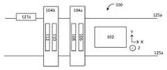
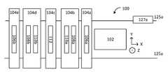
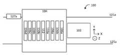
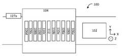
일 양상에서, 적층 제조 장치는, 플랫폼, 플랫폼 위에 위치되는 하나 이상의 지지부, 플랫폼 및 하나 이상의 지지부 중 적어도 하나에 결합되고 하나 이상의 지지부가 플랫폼에 걸쳐 스캐닝하도록 그들 사이의 상대적인 움직임을 생성하도록 구성되는 액추에이터, 플랫폼에 의해 지지되는 구축 영역 상에 분말의 복수의 연속적인 층들을 분배하도록 구성되는 제1 분배기 시스템, 구축 영역 상에 결합제 물질을 분배하도록 구성되는 제2 분배기 시스템, 및 결합제 물질을 고화시키기 위해 플랫폼을 향해 방사선을 방출하도록 구성되는 에너지 소스를 포함한다. 제1 분배기 시스템은, 하나 이상의 지지부 중에서 제1 지지부에 부착되고 그와 함께 이동하고 구축 영역 상에 제1 분말을 선택적으로 분배하도록 구성되는 제1 분말 분배기를 포함한다. 제2 분배기 시스템은, 분말 및 결합제 물질을 갖는, 구축되는 부품의 단면 부분에 대응하는 층의 용적을 형성하기 위해, 구축 영역에서 분말의 최상위 층에 복셀별 기반으로 제1 결합제 물질을 선택적으로 분배하도록 구성되는 제1 결합제 물질 분배기를 포함한다.In one aspect, an additive manufacturing apparatus includes a platform, one or more supports positioned over the platform, an actuator coupled to at least one of the platform and one or more supports and configured to generate relative movement between the one or more supports to scan across the platform. , a first dispenser system configured to dispense a plurality of successive layers of powder on the buildup area supported by the platform, a second dispenser system configured to dispense a binder material over the buildup area, and to solidify the binder material. and an energy source configured to emit radiation towards the platform. The first dispenser system includes a first powder dispenser attached to and moving with a first one of the one or more supports and configured to selectively dispense a first powder onto the building area. The second dispenser system selectively dispenses the first binder material on a voxel-by-voxel basis to the uppermost layer of powder in the building area to form a volume of a layer having the powder and binder material corresponding to a cross-sectional portion of the part being built up. and a first binder material dispenser configured to
구현들은 다음의 특징들 중 하나 이상을 포함할 수 있다.Implementations may include one or more of the following features.
제1 지지부는 제1 축을 따라 이동가능할 수 있고, 제1 분말 분배기는, 제1 축에 대해 영이 아닌 각도로 있는, 예컨대 수직인 제2 축을 따라 스트립(strip)으로 분말을 선택적으로 분배하도록 구성될 수 있다. 제1 분말 분배기는, 제2 축을 따라 복셀별 기반으로 또는 제2 축을 따라 구역별 기반으로 분말을 선택적으로 분배하도록 구성될 수 있으며, 구역들은 복셀들보다 크다.The first support may be movable along a first axis, and the first powder dispenser may be configured to selectively dispense powder in strips along a second axis at a non-zero angle relative to the first axis, such as perpendicular to the first axis. can The first powder dispenser may be configured to selectively dispense the powder on a per-voxel basis along a second axis or on a per-zone basis along the second axis, the zones being larger than the voxels.
제1 결합제 물질 분배기 및 에너지 소스는 제1 지지부에 부착되고 그와 함께 이동할 수 있다. 제1 결합제 물질 분배기는, 제2 축을 따라 스트립으로 결합제 물질을 선택적으로 분배하도록 구성될 수 있다. 제1 결합제 물질은 치밀화 물질을 포함할 수 있다.A first binder substance dispenser and an energy source are attached to and moveable with the first support. The first binder material dispenser may be configured to selectively dispense binder material in strips along a second axis. The first binder material may include a densifying material.
제1 결합제 물질 분배기 및 에너지 소스는 하나 이상의 지지부 중에서 제2 지지부에 부착되고 그와 함께 이동할 수 있고, 제2 지지부는 제3 축을 따라 이동가능할 수 있고, 제1 결합제 물질 분배기는 제3 축에 대해 영이 아닌 각도로 있는, 예컨대 수직인 제4 축을 따라 스트립으로 결합제 물질을 선택적으로 분배하도록 구성될 수 있다. 제3 축은 제1 축과 평행할 수 있다. 제4 축은 제3 축과 평행할 수 있다. 제1 지지부 및 제2 지지부는 안내 레일에 연결되고 안내 레일 상에서 독립적으로 이동가능할 수 있다. 제1 지지부는 제1 안내 레일 상에서 이동가능할 수 있고, 제2 지지부는 제1 안내 레일과 평행한 제2 안내 레일 상에서 이동가능할 수 있다. 제3 축은 제1 축에 수직일 수 있다. 제4 축은 제3 축에 수직일 수 있다.The first binder material dispenser and the energy source may be attached to and moveable with a second support of the one or more supports, the second support may be movable along a third axis, the first binder material dispenser being relative to a third axis and may be configured to selectively dispense the binder material in strips along a fourth axis at a non-zero angle, such as perpendicular. The third axis may be parallel to the first axis. The fourth axis may be parallel to the third axis. The first support and the second support are connected to the guide rail and may be independently movable on the guide rail. The first support may be movable on the first guide rail and the second support may be movable on a second guide rail parallel to the first guide rail. The third axis may be perpendicular to the first axis. The fourth axis may be perpendicular to the third axis.
제1 분말 분배기는, 복셀별 기반으로 분말을 선택적으로 분배하도록 구성될 수 있다. 제1 분말 분배기는, 구역별 기반으로 분말을 선택적으로 분배하도록 구성될 수 있으며, 구역들은 복셀들보다 크다. 제1 분말 분배기는 제1 복수의 개별적으로 제어가능한 오리피스들을 가질 수 있으며, 제1 복수의 오리피스들의 각각의 오리피스는 제1 분말을 제어가능하게 전달하도록 구성된다. 제1 분말 분배기는 구축 영역의 폭에 걸쳐 있을 수 있다. 제1 분배기 시스템은 복수의 제1 분말 분배기들을 포함할 수 있으며, 각각의 제1 분말 분배기는 제1 지지부에 부착된다. 복수의 제1 분말 분배기들은, 구축 영역의 폭을 커버하도록, 엇갈린 패턴으로 배열될 수 있다.The first powder dispenser may be configured to selectively dispense the powder on a voxel-by-voxel basis. The first powder dispenser may be configured to selectively dispense the powder on a per-zone basis, the zones being larger than the voxels. The first powder dispenser may have a first plurality of individually controllable orifices, each orifice of the first plurality of orifices configured to controllably deliver a first powder. The first powder dispenser may span the width of the build area. The first dispenser system may include a plurality of first powder dispensers, each first powder dispenser attached to the first support. The plurality of first powder dispensers may be arranged in a staggered pattern to cover the width of the building area.
제어기는, 제조될 물체의 층에서 결합제 물질이 고화될 패턴을 식별하는 데이터 객체를 저장하도록 구성되는 메모리를 가질 수 있다. 제어기는, 층에 대해, 액추에이터로 하여금, 지지부와 플랫폼 사이의 상대적인 움직임을 생성하게 하고, 제1 분배기 시스템으로 하여금, 지지부가 플랫폼에 걸쳐 스캐닝함에 따라 구축되는 부품의 단면 부분을 포괄하는 구역들에서 분말의 층을 분배하게 하고, 제2 분배기 시스템으로 하여금, 구축되는 부품의 단면에 대응하는 분말과 결합제 물질의 조합된 층을 제공하도록 데이터 객체에 기반한 패턴으로 분말의 층 상에 결합제 물질의 층을 분배하게 하고, 패턴에 따라 조합된 층에서 결합제 물질을 고화시키도록 에너지 소스를 제어하도록 구성될 수 있다.The controller may have a memory configured to store a data object identifying a pattern in which the binder material will solidify in the layer of the object to be manufactured. The controller causes, relative to the floor, to cause the actuator to generate relative motion between the support and the platform, and cause the first distributor system to cause the first distributor system in regions encompassing a cross-sectional portion of the part to be built up as the support scans across the platform. dispensing the layer of powder and causing the second dispenser system to dispense a layer of binder material onto the layer of powder in a pattern based on the data object to provide a combined layer of powder and binder material corresponding to a cross-section of the part being constructed. dispensing and controlling the energy source to solidify the binder material in the combined layer according to the pattern.
제1 결합제 물질은 치밀화 물질을 포함할 수 있다.The first binder material may include a densifying material.
제3 분배 시스템은, 분말의 층 또는 분말과 결합제 물질의 조합된 층에 치밀화 물질을 전달하도록 구성될 수 있다. 제1 치밀화제 분배기는 복수의 개별적으로 제어가능한 오리피스들을 포함할 수 있으며, 제1 치밀화제 분배기의 복수의 오리피스들의 각각의 오리피스는 치밀화 물질을 제어가능하게 전달하도록 구성된다. 제1 결합제 분배기는, 제1 결합제 분배기의 움직임의 방향을 따라 제1 치밀화제 분배기 전에 또는 그 후에 위치될 수 있다. 제1 치밀화제 분배기는, 제1 지지부에 부착될 수 있고 그와 함께 이동한다. 제1 결합제 물질 분배기 및 에너지 소스는, 하나 이상의 지지부 중에서, 제1 지지부에 부착되고 그와 함께 이동할 수 있거나, 제2 지지부에 부착되고 그와 함께 이동할 수 있다. 제2 지지부는 제3 축을 따라 이동가능할 수 있고, 제1 치밀화제 분배기는, 제3 축에 대해 영이 아닌 각도로 있는 제4 축을 따라 스트립으로 치밀화제 물질을 선택적으로 분배하도록 구성될 수 있다. 제1 결합제 물질 분배기 및 에너지 소스는 제2 지지부에 부착되고 그와 함께 이동할 수 있다.The third dispensing system may be configured to deliver the densified material to a layer of powder or a combined layer of powder and binder material. The first densifying agent dispenser may include a plurality of individually controllable orifices, wherein each orifice of the plurality of orifices of the first densifying agent dispenser is configured to controllably deliver the densifying material. The first binder dispenser may be positioned before or after the first densifying agent dispenser along the direction of movement of the first binder dispenser. The first densifying agent dispenser may be attached to and move with the first support. The first binder substance dispenser and the energy source may be attached to and movable with the first support, or attached to and movable with the second support, among the one or more supports. The second support may be movable along a third axis and the first densifying agent dispenser may be configured to selectively dispense the densifying agent material in strips along a fourth axis at a non-zero angle with respect to the third axis. The first binder substance dispenser and the energy source are attached to and moveable with the second support.
제3 분배기 시스템은, 구축 영역 상에 치밀화 물질을 선택적으로 분배하도록 구성되는 제2 치밀화제 분배기를 포함할 수 있다. 제1 치밀화제 분배기 및 제2 치밀화제 분배기는 제1 지지부에 부착되고 그와 함께 이동할 수 있다. 제1 치밀화제 분배기는 하나 이상의 지지부 중에서 제2 지지부에 부착될 수 있고 그와 함께 이동하며, 제2 치밀화제 분배기는 제3 지지부에 부착될 수 있고 그와 함께 이동한다. 제1 결합제 분배기 및 에너지 소스는 하나 이상의 지지부 중에서 제4 지지부에 부착될 수 있고 그와 함께 이동한다.The third dispenser system can include a second densifying agent dispenser configured to selectively dispense the densifying material onto the build area. The first densifying agent dispenser and the second densifying agent dispenser are attached to and movable with the first support. A first densifying agent dispenser may be attached to and move with a second one of the one or more supports, and a second densifying agent dispenser may be attached to and move with the third support. The first binder dispenser and energy source may be attached to and move with a fourth one of the one or more supports.
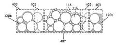
치밀화 물질은, 분말과 동일한 조성을 갖지만 더 작은 평균 직경을 가질 수 있다. 치밀화 물질은, 내부에 나노입자들이 분산되어 있는 졸-겔을 포함할 수 있다. 졸-겔은, 제1 분말과 동일한 조성을 갖는 세라믹에 대한 전구체를 포함할 수 있다. 제3 분배기 시스템은, 구축 영역 상에 치밀화 물질을 선택적으로 분배하도록 구성되는 제1 치밀화제 분배기를 포함할 수 있다.The densified material may have the same composition as the powder but have a smaller average diameter. The densification material may include a sol-gel in which nanoparticles are dispersed. The sol-gel may include a precursor to a ceramic having the same composition as the first powder. The third dispenser system can include a first densifying agent dispenser configured to selectively dispense a densifying material onto the build area.
제1 치밀화제 분배기는, 제1 지지부에 부착될 수 있고 그와 함께 이동한다. 제1 결합제 물질 분배기 및 에너지 소스는, 하나 이상의 지지부 중에서, 제1 지지부에 부착되고 그와 함께 이동하거나, 제2 지지부에 부착되고 그와 함께 이동할 수 있다. 제1 지지부는 제1 축을 따라 이동가능할 수 있고, 제2 지지부는 제1 지지부와 독립적으로 제1 축과 평행하게 이동가능하다. 제1 지지부는 제1 축을 따라 이동가능할 수 있고, 제2 지지부는 제1 지지부와 독립적으로 제1 축에 수직으로 이동가능할 수 있다. 제1 지지부는 제1 축을 따라 이동가능할 수 있고, 제2 지지부는 제1 지지부와 독립적으로 제2의 제1 축을 따라 이동가능할 수 있고, 제1 결합제 물질 분배기는, 제2 축에 대해 영이 아닌 각도로 있는 축을 따라 스트립으로 결합제 물질을 선택적으로 분배하도록 구성될 수 있다.The first densifying agent dispenser may be attached to and move with the first support. The first binder substance dispenser and energy source may be attached to and moved with the first support, or attached to and moved with the second support, among the one or more supports. The first support may be movable along a first axis, and the second support may be movable parallel to the first axis independently of the first support. The first support may be movable along the first axis and the second support may be movable perpendicular to the first axis independently of the first support. The first support may be movable along a first axis, the second support may be movable along a second first axis independently of the first support, and wherein the first binder substance dispenser is disposed at a non-zero angle relative to the second axis. and may be configured to selectively dispense the binder material in strips along an axis in which the
제1 치밀화제 분배기는 하나 이상의 지지부 중에서 제2 지지부에 부착될 수 있고 그와 함께 이동하며, 제2 지지부는 제3 축을 따라 이동가능할 수 있다. 제1 치밀화제 분배기는, 제3 축에 대해 영이 아닌 각도로 있는 제4 축을 따라 스트립으로 치밀화제 물질을 선택적으로 분배하도록 구성될 수 있다. 제3 축은 제1 축과 실질적으로 평행할 수 있다. 제1 결합제 물질 분배기 및 에너지 소스는 제2 지지부에 부착되고 그와 함께 이동할 수 있다.The first densifying agent dispenser may be attached to and move with a second one of the one or more supports, and the second support may be movable along a third axis. The first densifying agent dispenser may be configured to selectively dispense the densifying agent material in strips along a fourth axis at a non-zero angle with respect to the third axis. The third axis may be substantially parallel to the first axis. The first binder substance dispenser and the energy source are attached to and moveable with the second support.
제1 결합제 분배기 및 제1 치밀화제 분배기는, 제1 결합제 분배기가 움직임의 방향을 따라 제1 치밀화제 분배기 전에 위치되도록 구성될 수 있다. 제1 결합제 분배기 및 제1 치밀화제 분배기는, 제1 결합제 분배기가 움직임의 방향을 따라 제1 치밀화제 분배기 후에 위치되도록 구성될 수 있다.The first binder dispenser and the first densifying agent dispenser may be configured such that the first binder dispenser is positioned before the first densifying agent dispenser along a direction of movement. The first binder dispenser and the first densifying agent dispenser may be configured such that the first binder dispenser is positioned after the first densifying agent dispenser along a direction of movement.
제3 분배기 시스템은, 구축 영역 상에 치밀화 물질을 선택적으로 분배하도록 구성되는 제2 치밀화제 분배기를 포함할 수 있다. 제1 치밀화제 분배기 및 제2 치밀화제 분배기는 제1 지지부에 부착되고 그와 함께 이동할 수 있다. 제1 치밀화제 분배기는 하나 이상의 지지부 중에서 제2 지지부에 부착되고 그와 함께 이동할 수 있으며, 제2 치밀화제 분배기는 제3 지지부에 부착되고 그와 함께 이동할 수 있다. 제1 결합제 분배기 및 에너지 소스는 하나 이상의 지지부 중에서 제4 지지부에 부착되고 그와 함께 이동할 수 있다. 치밀화 물질은, 분말과 동일한 물질 조성을 갖지만 더 작은 평균 직경 입자 크기를 가질 수 있다.The third dispenser system can include a second densifying agent dispenser configured to selectively dispense the densifying material onto the build area. The first densifying agent dispenser and the second densifying agent dispenser are attached to and movable with the first support. A first densifying agent dispenser is attached to and movable with a second one of the one or more supports, and a second densifying agent dispenser is attached to and movable with a third support. The first binder dispenser and the energy source are attached to and moveable with a fourth one of the one or more supports. The densified material may have the same material composition as the powder but a smaller average diameter particle size.
제4 분배기 시스템은 구축 영역 상에 제2 분말의 복수의 연속적인 층들을 분배하도록 구성될 수 있으며, 제4 분배기 시스템은, 구축 영역 상에 제2 분말을 선택적으로 분배하도록 구성되는 제2 분말 분배기를 포함한다. 제2 분말은 제1 분말과 조성이 상이할 수 있다. 제1 분말은 금속성 입자들을 포함할 수 있고, 제2 분말은 세라믹 또는 플라스틱 입자들을 포함할 수 있다. 제1 분말은 세라믹 입자들을 포함할 수 있고, 제2 분말은 플라스틱 입자들을 포함한다. 제2 분말은 제1 분말과 동일한 물질 조성을 갖지만 상이한 크기 분포를 가질 수 있다.The fourth dispenser system may be configured to dispense a plurality of successive layers of a second powder on the build-up area, wherein the fourth dispenser system is configured to selectively dispense a second powder on the build-up area. includes The second powder may have a different composition from the first powder. The first powder may include metallic particles and the second powder may include ceramic or plastic particles. The first powder may include ceramic particles and the second powder may include plastic particles. The second powder may have the same material composition as the first powder but a different size distribution.
제2 분말 분배기는 복수의 개별적으로 제어가능한 오리피스들을 포함할 수 있으며, 제2 분말 분배기의 복수의 오리피스들의 각각의 오리피스는 제2 분말을 제어가능하게 전달하도록 구성된다. 제2 분말 분배기는 제1 지지부에 부착되고 그와 함께 이동할 수 있다. 제1 결합제 분배기 및 에너지 소스는, 하나 이상의 지지부 중에서, 제1 지지부에 의해 지지될 수 있거나, 제2 지지부에 의해 지지되고 그와 함께 이동가능할 수 있다. 제2 분말 분배기는, 하나 이상의 지지부 중에서 제2 지지부에 의해 지지되고 그와 함께 이동가능할 수 있다.The second powder dispenser may include a plurality of individually controllable orifices, wherein each orifice of the plurality of orifices of the second powder dispenser is configured to controllably deliver the second powder. The second powder dispenser is attached to the first support and is movable therewith. The first binder dispenser and energy source may be supported by a first support or may be supported by and movable with a second support, among the one or more supports. The second powder dispenser may be supported by and movable with a second one of the one or more supports.
제2 지지부는 제3 축을 따라 이동가능할 수 있고, 제2 분말 분배기는, 제3 축에 대해 영이 아닌 각도로 있는 제4 축을 따라 스트립으로 제2 분말을 선택적으로 분배하도록 구성될 수 있다. 제1 결합제 물질 분배기 및 에너지 소스는, 하나 이상의 지지부 중에서, 제2 지지부에 부착되고 그와 함께 이동하거나, 제3 지지부에 부착되고 그와 함께 이동할 수 있다. 제3 축은 제1 축과 실질적으로 평행할 수 있다. 제4 축은 제2 축과 실질적으로 평행할 수 있다. 제4 축은 제3 축에 수직일 수 있다. 제1 분말 분배기 및 제2 분말 분배기는, 제1 분말 분배기가 움직임의 방향을 따라 제2 치밀화제 분배기 전에 위치되도록 구성될 수 있다. 제3 축은 제1 축에 실질적으로 수직일 수 있다. 제1 지지부 및 제2 지지부는, 동일한 안내 레일 상에서 이동가능하거나 별개의 평행한 안내 레일들 상에서 이동가능할 수 있다.The second support may be movable along a third axis and the second powder dispenser may be configured to selectively dispense the second powder in strips along a fourth axis at a non-zero angle with respect to the third axis. The first binder substance dispenser and energy source may be attached to and moved with the second support, or attached to and moved with the third support, among the one or more supports. The third axis may be substantially parallel to the first axis. The fourth axis may be substantially parallel to the second axis. The fourth axis may be perpendicular to the third axis. The first powder dispenser and the second powder dispenser may be configured such that the first powder dispenser is positioned before the second densifying agent dispenser along the direction of movement. The third axis may be substantially perpendicular to the first axis. The first support and the second support may be movable on the same guide rail or movable on separate parallel guide rails.
제어기는, 제조될 물체의 층에 적어도 대응하는 데이터 객체를 저장하도록 구성되는 메모리를 가질 수 있고, 제어기는, 제1 분배기 시스템으로 하여금, 제조될 물체에 대응하는 구역에서 제1 분말을 분배하게 하고, 제4 분배기 시스템으로 하여금, 제조될 물체들에 대응하지 않는 구역에서 제2 분말을 분배하게 하도록 구성될 수 있다.The controller may have a memory configured to store a data object corresponding at least to a layer of the object to be manufactured, the controller causing the first dispenser system to dispense the first powder in a region corresponding to the object to be manufactured, and , cause the fourth dispenser system to dispense the second powder in an area that does not correspond to the objects to be manufactured.
제1 분말은 금속 입자들을 포함할 수 있고, 제2 분말은 세라믹 입자들을 포함할 수 있다. 제1 분말은 금속 또는 세라믹 입자들을 포함할 수 있고, 제2 분말은 플라스틱 입자들을 포함할 수 있다. 제어기는, 제1 분배기 시스템으로 하여금, 제1 분말 상에만 결합제 물질을 분배하게 하도록 구성될 수 있다. 제어기는, 제1 분배기 시스템으로 하여금, 제1 분말 및 제2 분말 둘 모두 상에 결합제 물질을 분배하게 하도록 구성될 수 있다.The first powder may include metal particles, and the second powder may include ceramic particles. The first powder may include metal or ceramic particles, and the second powder may include plastic particles. The controller may be configured to cause the first dispenser system to dispense the binder material onto the first powder only. The controller may be configured to cause the first dispenser system to dispense the binder material onto both the first powder and the second powder.
제어기는, 제조될 물체의 층에 적어도 대응하는 데이터 객체를 저장하도록 구성되는 메모리를 갖고, 제어기는, 제1 분배기 시스템으로 하여금, 제조될 물체에 대응하는 제1 구역에서 제1 분말을 분배하게 하고, 제4 분배기 시스템으로 하여금, 제1 구역의 일부분에서 제2 분말을 분배하게 하도록 구성된다. 제2 분말은, 제1 분말에 대한 치밀화 물질을 포함할 수 있다.The controller has a memory configured to store a data object corresponding at least to a layer of the object to be manufactured, wherein the controller causes the first dispenser system to dispense the first powder in a first zone corresponding to the object to be manufactured; , configured to cause the fourth dispenser system to dispense the second powder in the portion of the first zone. The second powder may include a densification material for the first powder.
제1 분배기 시스템은, 제1 분말을 분배하기 위한 제2 분말 분배기를 포함할 수 있다. 제2 분배기 시스템은, 결합제 물질을 분배하기 위한 제2 결합제 물질 분배기를 포함할 수 있다. 제1 분말 물질 분배기, 제2 분말 물질 분배기, 제1 결합제 물질 분배기, 및 제2 결합제 물질 분배기는 제1 지지부에 부착되고 그와 함께 이동할 수 있다. 제1 결합제 물질 분배기, 제2 결합제 물질 분배기, 및 에너지 소스는 제2 지지부에 부착되고 그와 함께 이동할 수 있고, 제2 결합제 물질 분배기는 제3 지지부에 부착되고 그와 함께 이동한다. 제1 지지부, 제2 지지부, 및 제3 지지부는 제1 축을 따라 독립적으로 이동가능할 수 있다. 제3 축을 따라, 제1 분말 분배기, 제1 결합제 물질 분배기, 에너지 소스, 제2 결합제 물질 분배기, 및 제2 분말 분배기가 전술된 순서로 배열될 수 있다.The first dispenser system may include a second powder dispenser for dispensing the first powder. The second dispenser system may include a second binder material dispenser for dispensing the binder material. The first powder material dispenser, the second powder material dispenser, the first binder material dispenser, and the second binder material dispenser are attached to the first support and movable therewith. The first binder material distributor, the second binder material distributor, and the energy source are attached to and moveable with the second support, and the second binder material distributor is attached to and moves with the third support. The first support, the second support, and the third support may be independently movable along the first axis. Along the third axis, the first powder dispenser, the first binder material dispenser, the energy source, the second binder material dispenser, and the second powder dispenser may be arranged in the order described above.
제어기는, 제조될 물체의 연속적인 층들에서 결합제 물질이 고화될 패턴을 식별하는 데이터 객체를 저장하도록 구성되는 메모리를 가질 수 있고, 제어기는, 제1 분말 분배기로 하여금, 제1 분말 분배기가 제1 축을 따라 제1 방향으로 이동함에 따라 분말의 제1 층을 분배하게 하고, 제1 결합제 분배기로 하여금, 제1 결합제 물질 분배기가 제1 축을 따라 제1 방향으로 이동함에 따라 분말과 결합제 물질의 제1 조합된 층을 제공하도록 분말의 제1 층 상에 결합제 물질의 제1 층을 분배하게 하고, 패턴에 따라 제1 조합된 층에서 결합제 물질을 고화시키도록 에너지 소스를 제어하고, 제2 분배기 시스템으로 하여금, 제2 분말 분배기가 제1 축을 따라 제1 방향과 반대인 제2 방향으로 이동함에 따라 분말의 제2 층을 분배하게 하고, 제2 결합제 분배기로 하여금, 제2 결합제 분배기가 제2 방향으로 이동함에 따라 분말과 결합제 물질의 제2 조합된 층을 제공하도록 분말의 제2 층 상에 결합제 물질의 제2 층을 분배하게 하고, 패턴에 따라 제2 조합된 층에서 결합제 물질을 고화시키도록 에너지 소스를 제어하도록 구성될 수 있다.The controller may have a memory configured to store a data object identifying a pattern by which the binder material will solidify in successive layers of the object to be manufactured, the controller causing the first powder dispenser to cause the first powder dispenser to dispensing a first layer of powder as it moves in a first direction along an axis, causing a first binder dispenser to cause a first binder material of powder and binder material as the first binder material dispenser moves in a first direction along the first axis. Dispensing a first layer of binder material on the first layer of powder to provide a combined layer, controlling the energy source to solidify the binder material in the first combined layer according to a pattern, and to a second distributor system dispensing a second layer of powder as the second powder dispenser moves along the first axis in a second direction opposite the first direction, causing the second binder dispenser to cause the second binder dispenser to move in the second direction. energy to dispense a second layer of binder material on the second layer of powder to provide a second combined layer of powder and binder material as it travels, and to solidify the binder material in the second combined layer according to a pattern It may be configured to control the source.
광원은, 최상위 층과 함께 스트라이프(stripe)를 조명하도록 구성될 수 있다. 에너지 소스는 복수의 지지부들 중에서 일 지지부에 결합될 수 있고, 지지부는, 구축 영역에 걸쳐 스트라이프를 스위핑하도록 스트라이프에 대해 영이 아닌 각도로, 예컨대 직각으로 있는 축을 따라 이동가능할 수 있다. 에너지 소스는, 복수의 독립적으로 제어가능한 광원들을 포함할 수 있다. 광원들은 발광 다이오드(LED)들일 수 있다. 광원들은 UV 또는 IR 광원들일 수 있다.The light source may be configured to illuminate the stripe together with the uppermost layer. The energy source may be coupled to a support of the plurality of supports, the support may be movable along an axis at a non-zero angle relative to the stripe, such as at right angles to the stripe to sweep the stripe across the building area. The energy source may include a plurality of independently controllable light sources. The light sources may be light emitting diodes (LEDs). The light sources may be UV or IR light sources.
제1 분배기 시스템은, 플랫폼에 의해 지지되는 구축 영역 상에 분말의 복수의 연속적인 층들을 분배하도록 구성될 수 있고, 제1 분배기 시스템은, 하나 이상의 지지부 중에서 제1 지지부에 부착되고 그와 함께 이동하고 구축 영역 상에 제1 분말을 선택적으로 분배하도록 구성되는 제1 분말 분배기, 및 구축 영역 상에 제2 분말을 선택적으로 분배하도록 구성되는 제2 분말 분배기를 포함할 수 있다.The first dispenser system may be configured to dispense a plurality of successive layers of powder on a building area supported by the platform, the first dispenser system being attached to and moving with a first one of the one or more supports. and a first powder dispenser configured to selectively dispense a first powder onto the build-up area, and a second powder dispenser configured to selectively dispense a second powder onto the build-up area.
제1 분말 분배기는, 제1 복수의 개별적으로 제어가능한 오리피스들을 포함할 수 있다. 제1 분말 분배기의 제1 복수의 오리피스들의 각각의 오리피스는, 제1 분말을 제어가능하게 전달하도록 구성될 수 있다. 제2 분말 분배기는, 제2 복수의 개별적으로 제어가능한 오리피스들을 포함할 수 있다. 제2 분말 분배기의 제2 복수의 오리피스들의 각각의 오리피스는, 제2 분말을 제어가능하게 전달하도록 구성될 수 있다.The first powder dispenser may include a first plurality of individually controllable orifices. Each orifice of the first plurality of orifices of the first powder dispenser may be configured to controllably deliver the first powder. The second powder dispenser may include a second plurality of individually controllable orifices. Each orifice of the second plurality of orifices of the second powder dispenser may be configured to controllably deliver the second powder.
제2 분말 분배기는 제1 지지부에 부착되고 그와 함께 이동할 수 있다. 제1 결합제 분배기 및 에너지 소스는 제1 지지부에 의해 지지될 수 있다. 제2 분말 분배기는, 하나 이상의 지지부 중에서 제2 지지부에 의해 지지되고 그와 함께 이동가능할 수 있다. 제2 지지부는 제3 축을 따라 이동가능할 수 있고, 제2 분말 분배기는, 제3 축에 대해 영이 아닌 각도로 있는 제4 축을 따라 스트립으로 제2 분말을 선택적으로 분배하도록 구성될 수 있다. 제1 결합제 물질 분배기 및 에너지 소스는 하나 이상의 지지부 중에서 제3 지지부에 부착되고 그와 함께 이동할 수 있다. 제3 축은 제1 축과 실질적으로 평행할 수 있다. 제3 축은 제1 축에 실질적으로 수직일 수 있다.The second powder dispenser is attached to the first support and is movable therewith. The first binder dispenser and the energy source may be supported by the first support. The second powder dispenser may be supported by and movable with a second one of the one or more supports. The second support may be movable along a third axis and the second powder dispenser may be configured to selectively dispense the second powder in strips along a fourth axis at a non-zero angle with respect to the third axis. The first binder substance dispenser and the energy source are attached to and moveable with a third one of the one or more supports. The third axis may be substantially parallel to the first axis. The third axis may be substantially perpendicular to the first axis.
제어기는, 제조될 물체의 층에 적어도 대응하는 데이터 객체를 저장하도록 구성되는 메모리를 가질 수 있다.The controller may have a memory configured to store a data object corresponding at least to a layer of an object to be manufactured.
제어기는, 제1 분배기 시스템으로 하여금, 제조될 물체에 대응하는 구역에서 제1 분말을 분배하게 하고, 제4 분배기 시스템으로 하여금, 제조될 물체들에 대응하지 않는 구역에서 제2 분말을 분배하게 하도록 구성될 수 있다. 제1 분말은 금속 입자들일 수 있고 제2 분말은 세라믹 입자들일 수 있거나, 또는 제1 분말은 금속 또는 세라믹 입자들일 수 있고 제2 분말은 플라스틱 입자들일 수 있다. 제어기는, 제1 분배기 시스템으로 하여금, 제1 분말 상에만 결합제 물질을 분배하게 하도록 구성될 수 있다. 제어기는, 제1 분배기 시스템으로 하여금, 제1 분말 및 제2 분말 둘 모두 상에 결합제 물질을 분배하게 하도록 구성될 수 있다.The controller causes the first dispenser system to dispense the first powder in an area corresponding to the object to be manufactured, and cause the fourth dispenser system to dispense the second powder in an area not corresponding to the object to be manufactured. can be configured. The first powder can be metal particles and the second powder can be ceramic particles, or the first powder can be metal or ceramic particles and the second powder can be plastic particles. The controller may be configured to cause the first dispenser system to dispense the binder material onto the first powder only. The controller may be configured to cause the first dispenser system to dispense the binder material onto both the first powder and the second powder.
제어기는, 제1 분배기 시스템으로 하여금, 제조될 물체에 대응하는 제1 구역에서 제1 분말을 분배하게 하고, 제4 분배기 시스템으로 하여금, 제1 구역의 일부분에서 제2 분말을 분배하게 하도록 구성될 수 있다. 제2 분말은, 제1 분말에 대한 치밀화 물질일 수 있다.The controller may be configured to cause the first dispenser system to dispense the first powder in a first zone corresponding to the object to be manufactured, and cause the fourth dispenser system to dispense the second powder in a portion of the first zone. can The second powder may be a densification material for the first powder.
제2 분배기 시스템은, 결합제 물질을 분배하기 위한 제2 결합제 물질 분배기를 포함할 수 있다. 제1 분말 물질 분배기, 제2 분말 물질 분배기, 제1 결합제 물질 분배기, 및 제2 결합제 물질 분배기는 제1 지지부에 부착되고 그와 함께 이동할 수 있다. 제1 분말 분배기, 제1 결합제 물질 분배기, 에너지 소스, 제2 결합제 물질 분배기, 및 제2 분말 분배기는, 지지부에 걸쳐 제1 분말 분배기의 움직임의 방향을 따라 전술된 순서로 배열될 수 있다. 제2 분말은 제1 분말과 동일한 물질 조성 및 크기 분포를 가질 수 있다.The second dispenser system may include a second binder material dispenser for dispensing the binder material. The first powder material dispenser, the second powder material dispenser, the first binder material dispenser, and the second binder material dispenser are attached to the first support and movable therewith. The first powder dispenser, the first binder material dispenser, the energy source, the second binder material dispenser, and the second powder dispenser may be arranged in the order described above along the direction of movement of the first powder dispenser across the support. The second powder may have the same material composition and size distribution as the first powder.
제어기는, 제조될 물체의 연속적인 층들에서 결합제 물질이 고화될 패턴을 식별하는 데이터 객체를 저장하도록 구성되는 메모리를 가질 수 있다. 제어기는, 제1 분말 분배기로 하여금, 제1 분말 분배기가 제1 축을 따라 제1 방향으로 이동함에 따라 분말의 제1 층을 분배하게 하고, 제1 결합제 분배기로 하여금, 제1 결합제 물질 분배기가 제1 축을 따라 제1 방향으로 이동함에 따라 분말과 결합제 물질의 제1 조합된 층을 제공하도록 분말의 제1 층 상에 결합제 물질의 제1 층을 분배하게 하고, 패턴에 따라 제1 조합된 층에서 결합제 물질을 고화시키도록 에너지 소스를 제어하고, 제2 분배기 시스템으로 하여금, 제2 분말 분배기가 제1 축을 따라 제1 방향과 반대인 제2 방향으로 이동함에 따라 분말의 제2 층을 분배하게 하고, 제2 결합제 분배기로 하여금, 제2 결합제 분배기가 제2 방향으로 이동함에 따라 분말과 결합제 물질의 제2 조합된 층을 제공하도록 분말의 제2 층 상에 결합제 물질의 제2 층을 분배하게 하고, 패턴에 따라 제2 조합된 층에서 결합제 물질을 고화시키도록 에너지 소스를 제어하도록 구성될 수 있다.The controller may have a memory configured to store a data object identifying a pattern in which the binder material will solidify in successive layers of the object to be fabricated. The controller causes the first powder dispenser to dispense a first layer of powder as the first powder dispenser moves along the first axis in a first direction, and causes the first binder dispenser to cause the first binder substance dispenser to move in the first direction. dispensing a first layer of binder material on the first layer of powder to provide a first combined layer of powder and binder material as it moves in a first direction along one axis, and in a pattern in the first combined layer control the energy source to solidify the binder material, cause the second dispenser system to dispense the second layer of powder as the second powder dispenser moves along the first axis in a second direction opposite the first direction; cause the second binder dispenser to dispense a second layer of binder material onto the second layer of powder to provide a second combined layer of powder and binder material as the second binder dispenser moves in the second direction; , to control the energy source to solidify the binder material in the second combined layer according to the pattern.
에너지 소스는, 최상위 층과 함께 스트라이프를 조명하도록 구성되는 광원을 포함할 수 있다. 에너지 소스는 복수의 지지부들 중에서 일 지지부에 결합될 수 있고, 지지부는, 구축 영역에 걸쳐 스트라이프를 스위핑하도록 스트라이프에 대해 영이 아닌 각도로 있는 축을 따라 이동가능할 수 있다. 에너지 소스는, 복수의 독립적으로 제어가능한 광원들을 포함할 수 있다.The energy source may include a light source configured to illuminate the stripe together with the uppermost layer. The energy source may be coupled to a support of the plurality of supports, the support may be movable along an axis at a non-zero angle with respect to the stripe to sweep the stripe across the building area. The energy source may include a plurality of independently controllable light sources.
오븐은 플랫폼 상에 제조된 그린 부품을 소결시킬 수 있다. 로봇은 그린 부품을 플랫폼으로부터 오븐으로 이송할 수 있다. 식각 시스템은 결합제 물질을 식각하여 제거할 수 있다. 밀봉된 하우징은, 플랫폼, 하나 이상의 지지부, 제1 분배기 시스템, 제2 분배기 시스템, 및 에너지 소스를 에워싸는 챔버를 형성할 수 있다. 펌프는 챔버를 진공배기할 수 있다. 가스 공급부는, 불활성인 가스를 제1 분말 및 제1 결합제 물질에 제공할 수 있다.The oven can sinter the green parts fabricated on the platform. The robot can transfer the green parts from the platform to the oven. The etch system may etch away the binder material. The sealed housing may define a chamber that encloses the platform, the one or more supports, the first distributor system, the second distributor system, and the energy source. The pump may evacuate the chamber. The gas supply may provide an inert gas to the first powder and the first binder material.
다른 양상에서, 그린 부품을 제조하는 방법은, 그린 부품의 복수의 층들을 연속적으로 형성하는 단계를 포함하며, 이 단계는, 각각의 층에 대해, 플랫폼 상의 구축 영역 상에 분말의 층을 선택적으로 분배하고 ― 선택적 분배는 구축 영역 전부보다는 작은 영역을 커버함 ―, 분말과 결합제 물질의 조합된 층을 형성하기 위해 분말의 층 상에 결합제 물질을 선택적으로 분배하고, 그린 부품의 복수의 층들의 층을 형성하기 위해 결합제 물질을 고화시키도록 플랫폼을 향해 방사선을 지향시키는 것에 의해 이루어지며, 분말은 고화된 결합제 물질에 의해 유지된다.In another aspect, a method of manufacturing a green part includes successively forming a plurality of layers of the green part, the step, for each layer, selectively depositing, for each layer, a layer of powder on a build area on a platform. dispensing - the selective dispensing covers an area less than all of the build area - selectively dispensing the binder material onto the layer of powder to form a combined layer of powder and binder material, a layer of a plurality of layers of the green part by directing radiation towards a platform to solidify the binder material to form a powder held by the solidified binder material.
구현들은 다음의 특징들 중 하나 이상을 포함할 수 있다. 그린 부품은, 분말을 고체 덩어리로 융착시키도록 처리될 수 있다. 그린 부품은, 그린 부품을 처리하기 위해 플랫폼으로부터 제거될 수 있다. 처리는, 어닐링, 소결, 및/또는 열간 등방압 가압 중 하나 이상을 포함한다.Implementations may include one or more of the following features. The green part can be treated to fuse the powder into a solid mass. The green part may be removed from the platform to process the green part. The treatment includes one or more of annealing, sintering, and/or hot isostatic pressing.
분말의 층을 선택적으로 분배하는 것은, 분말 분배기가 제1 축을 따라 이동하는 동안 분말 분배기의 복수의 독립적으로 제어가능한 노즐들로부터 분말을 분배하는 것을 포함할 수 있다. 노즐들은, 제1 축에 대해 영이 아닌 각도, 예컨대 직각으로 있는 제2 축을 따라 배열된다.Selectively dispensing the layer of powder may include dispensing the powder from a plurality of independently controllable nozzles of the powder dispenser while the powder dispenser moves along a first axis. The nozzles are arranged along a second axis that is at a non-zero angle with respect to the first axis, eg at right angles to the first axis.
결합제 물질을 선택적으로 분배하는 것은, 결합제 물질 분배기가 제3 축을 따라 이동하는 동안 결합제 물질 분배기의 복수의 독립적으로 제어가능한 노즐들로부터 결합제 물질을 분배하는 것을 포함할 수 있다. 노즐들은, 제3 축에 대해 영이 아닌 각도로 있는 제4 축을 따라 배열될 수 있다. 제3 축은 제1 축과 평행하거나 그에 수직일 수 있다. 제4 축은 제3 축에 수직일 수 있다.Selectively dispensing the binder material may include dispensing the binder material from a plurality of independently controllable nozzles of the binder material dispenser while the binder material dispenser moves along a third axis. The nozzles may be arranged along a fourth axis at a non-zero angle with respect to the third axis. The third axis may be parallel to or perpendicular to the first axis. The fourth axis may be perpendicular to the third axis.
방사선은, 제4 축과 평행한 스트라이프를 따라 에너지를 전달함으로써 플랫폼을 향해 지향될 수 있다. 층의 처리 동안 제3 축과 방사선의 스트라이프 사이에 일정한 거리가 유지될 수 있다. 일정한 거리를 유지하는 것은, 결합제 물질 분배기 및 광원을 동일한 지지부에 고정시키는 것을 포함할 수 있다. 플랫폼을 향해 방사선을 지향시키는 것은, 스트라이프를 따라 에너지를 선택적으로 전달하는 것을 포함할 수 있다.Radiation may be directed towards the platform by transmitting energy along a stripe parallel to the fourth axis. A constant distance may be maintained between the third axis and the stripe of radiation during processing of the layer. Maintaining the distance may include securing the binder material dispenser and the light source to the same support. Directing the radiation towards the platform may include selectively delivering energy along the stripes.
분말의 층을 선택적으로 분배하는 것은, 부품에 의해 커버되는 단면 영역의 둘레를 결정하는 것, 단면 영역의 둘레를 둘러싸는 완충 구역을 결정하는 것, 및 단면 영역 및 완충 구역과 겹치는 구역들로 분말을 분배하는 것을 포함할 수 있다. 분말의 층을 선택적으로 분배하는 것은, 완충 구역을 둘러싸는 유지 벽 구역을 결정하는 것, 및 단면 영역, 완충 구역, 및 유지 링 영역과 겹치는 구역들로 분말을 분배하는 것을 포함할 수 있다. 결합제 물질은, 완충 구역에 분배되는 것이 억제될 수 있다. 분말은, 유지 링 영역과 겹치는 구역들 외부에 분배되는 것이 억제될 수 있다. 분말의 층은 제1 분배기로부터 분배될 수 있고, 결합제 물질은 제2 분배기로부터 분배될 수 있고, 방사선은 에너지 소스로부터 생성될 수 있으며, 제1 분배기, 제2 분배기, 및 에너지 소스는 각각의 층이 처리된 후에 층의 두께와 대략적으로 동일한 높이만큼 들어올려질 수 있다.Selectively dispensing the layer of powder includes determining a perimeter of a cross-sectional area covered by the part, determining a buffer zone surrounding the perimeter of the cross-sectional area, and determining the cross-sectional area and the powder into regions overlapping the buffer zone. may include distributing Selectively dispensing the layer of powder may include determining a retaining wall region surrounding the buffer zone, and dispensing the powder into regions overlapping the cross-sectional region, the buffer region, and the retaining ring region. The binder material may be inhibited from dispensing to the buffer zone. Powder can be inhibited from being dispensed outside the regions overlapping the retaining ring region. The layer of powder may be dispensed from a first dispenser, the binder material may be dispensed from a second dispenser, and radiation may be generated from the energy source, the first dispenser, the second dispenser, and the energy source being in each layer. After this treatment, it can be lifted to a height approximately equal to the thickness of the layer.
본 명세서에 설명된 주제의 특정 실시예들은, 다음의 이점들 중 하나 이상을 실현하도록 구현될 수 있다. 적층 제조에서의 선택적 물질 분배는 공급원료 낭비 및 오염을 감소시킬 수 있고, 제조 효율을 개선할 수 있다. 치밀화 물질의 존재는, 제품 강성을 증가시키고 후처리 동안의 제품 수축을 감소시킬 수 있다.Certain embodiments of the subject matter described herein may be implemented to realize one or more of the following advantages. Selective material distribution in additive manufacturing can reduce feedstock waste and contamination, and can improve manufacturing efficiency. The presence of a densifying material can increase product stiffness and reduce product shrinkage during post-processing.
본 명세서에서 설명되는 주제의 하나 이상의 구현의 세부사항들은, 첨부된 도면들 및 아래의 설명에서 기재된다. 다른 잠재적인 특징들, 양상들 및 이점들은, 설명, 도면들 및 청구항들로부터 명백해질 것이다.The details of one or more implementations of the subject matter described herein are set forth in the accompanying drawings and the description below. Other potential features, aspects and advantages will become apparent from the description, drawings and claims.
도 1a-b는 각각, 적층 제조 장치의 구현의 개략적인 상면도를 도시한다.
도 1c는, 적층 제조 장치, 예컨대 도 1a의 적층 제조 장치의 개략적인 측면도를 도시한다.
도 1d는, 프린트헤드 조립체의 구현의 개략적인 측면도를 도시한다.
도 2a-2c는 각각, 적층 제조 장치의 구현의 개략적인 상면도를 도시한다.
도 3a-3e는 각각, 적층 제조 장치의 구현의 개략적인 상면도를 도시한다.
도 4a-b는 작업 중인 적층 제조 장치의 예들을 도시한다.
도 5a-b는 선택적으로 분말을 분배하는 분말 분배기의 예를 도시한다.
도 6은 하나 이상의 그린 부품을 형성하는 데 사용되는 프로세스의 흐름도이다.1A-B each show a schematic top view of an implementation of an additive manufacturing apparatus.
1C shows a schematic side view of an additive manufacturing apparatus, such as the additive manufacturing apparatus of FIG. 1A .
1D shows a schematic side view of an implementation of a printhead assembly.
2A-2C each show a schematic top view of an implementation of an additive manufacturing apparatus.
3A-3E each show a schematic top view of an implementation of an additive manufacturing apparatus.
4A-B show examples of an additive manufacturing apparatus in operation.
5a-b show an example of a powder dispenser that selectively dispenses powder.
6 is a flow diagram of a process used to form one or more green parts.
그린 부품들을 형성하기 위한 현재의 건식 분말 적층 제조 장치에서, 분말 분배기 시스템은 동작 동안 전체 구축 영역에 걸쳐 분말을 살포한다. 예컨대, 그러한 장치는, 구축 영역에 걸쳐 공급 물질들의 풀을 밀어내기 위해 롤러들 또는 블레이드 리코터들을 이용할 수 있다. 결과적으로, 분말은, 제조되는 부품에 대응하지 않는 구축 영역의 구역들에 분배된다.In current dry powder additive manufacturing apparatus for forming green parts, the powder dispenser system spreads the powder over the entire building area during operation. For example, such an apparatus may use rollers or blade coaters to push a pool of feed materials across the build area. As a result, the powder is distributed in areas of the building area that do not correspond to the part being manufactured.
그러나, 분말의 과도한 사용은, 제품 품질 및 제조 효율 둘 모두에 대해 몇몇 단점들을 야기한다. 특히, 분말의 상당 부분이 낭비되어, 부품 비용이 증가된다. 분말의 재활용은 실용적이지 않거나, 고가이거나, 또는 불량한 부품 품질로 이어질 수 있다. 예컨대, 회수된 분말을 사용하는 리코팅은 분말 오염의 기회들을 현저하게 증가시킨다. 분말 오염의 예들은, 결합제 물질 오염, 소결 오염, 산소 오염 등을 포함하지만 이에 제한되지 않는다. 오염된 분말 입자들은 최종 부품의 품질에 직접적인 영향을 준다. 또한, 분말은, 실제 프린팅이 발생하지 않는 영역들에 도포되어야 하며, 따라서, 시스템의 전체 프린팅 속도 및/또는 처리량이 둔화된다.However, excessive use of powder causes some disadvantages both with respect to product quality and manufacturing efficiency. In particular, a significant portion of the powder is wasted, increasing the cost of the parts. Recycling of powders can lead to impractical, expensive, or poor part quality. For example, coating with recovered powder significantly increases the chances of powder contamination. Examples of powder contamination include, but are not limited to, binder material contamination, sinter contamination, oxygen contamination, and the like. Contaminated powder particles directly affect the quality of the final part. In addition, the powder must be applied to areas where actual printing does not occur, thus slowing down the overall printing speed and/or throughput of the system.
이러한 문제들 중 일부를 해결하기 위한 기법은, 분말이 구축 영역에 걸쳐 선택적으로 전달될 수 있는 결합제 분사 적층 제조 장치를 사용하는 것이다. 그러한 장치는, 분말 사용을 감소시키고, 프린팅의 효율을 증가시키고, 분말 오염의 가능성을 감소시킬 수 있다.A technique to address some of these problems is to use a binder spray additive manufacturing apparatus in which powder can be selectively delivered across a build area. Such a device can reduce powder usage, increase the efficiency of printing, and reduce the likelihood of powder contamination.
분말 분배기 시스템은, 개별적으로 제어가능한 노즐들의 어레이를 이용할 수 있다. 분말 분배기가 플랫폼에 걸쳐 이동함에 따라, 분말 분배기 노즐들은, 플랫폼 상의 선택된 위치들에만 분말을 분배하도록 독립적으로 활성화될 수 있다.A powder dispenser system may utilize an array of individually controllable nozzles. As the powder dispenser moves across the platform, the powder dispenser nozzles can be independently activated to dispense powder only at selected locations on the platform.
또한, 결합제 분사 프로세스들은 종종, 그린 부품의 낮은 압착, 및 그에 따라, 후처리 동안의 과도한 수축을 초래한다. 분말 입자들 사이의 결합제 물질 입자들의 존재는, 후처리 동안의 결함들의 잠재적인 원인에 대한 공간을 추가로 생성한다. 그러나, 적층 제조 장치는, 층 내의 분배된 입자들 사이의 공극들을 감소시키기 위해 결합제 제형으로 치밀화 물질들을 포함할 수 있다. 치밀화 물질들은 또한, 후처리 동안 핵형성 부위의 역할을 하여 최종 제품의 강도를 개선할 수 있다.In addition, binder spraying processes often result in low compaction of the green part, and thus excessive shrinkage during post-processing. The presence of particles of binder material between the powder particles further creates space for a potential source of defects during post-processing. However, the additive manufacturing apparatus may include densifying materials in the binder formulation to reduce voids between the dispersed particles in the layer. Densified materials can also serve as nucleation sites during post-processing to improve the strength of the final product.
적층 제조 장치는, 프린팅 효율을 개선하기 위해 상이한 구성으로 만들어질 수 있다.The additive manufacturing apparatus can be made in different configurations to improve printing efficiency.
적층 제조 장치는 적어도, 상부에서 부품이 제조될 구축 영역을 제공하는 플랫폼, 분말 물질 분배기, 결합제 물질 분배기, 및 결합제 물질을 경화시키기 위한 에너지를 전달하기 위한 에너지 소스를 포함한다. 분말 물질 분배기, 결합제 물질 분배기, 및 에너지 소스는 하나 이상의 지지부에 의해 플랫폼 위에 유지될 수 있다.The additive manufacturing apparatus includes at least a platform providing a building area thereon from which the part is to be manufactured, a powder material distributor, a binder material distributor, and an energy source for delivering energy for curing the binder material. The powder material dispenser, binder material dispenser, and energy source may be held above the platform by one or more supports.
도 1a는, 적층 제조 장치(100)의 상면도의 예를 도시한다. 적층 제조 장치(100)는, 상부에서 부품이 제조될 구축 영역을 제공하는 플랫폼(102), 플랫폼(102) 위에 위치되는 지지부(104), 및 지지부(104) 상에 장착되는 프린트헤드 조립체(103)를 포함한다.1A shows an example of a top view of the
다양한 구성요소들, 예컨대, 플랫폼(102), 지지부(104), 및 프린트헤드 조립체(103)는, 제어된 동작 환경을 제공하는 밀봉된 하우징(180) 내에 에워싸일 수 있다. 하우징(180)은, 가스 소스, 예컨대 Ar 또는 N2에 결합되는 유입구(182), 및 배기 시스템, 예컨대 펌프에 결합되는 배출구(184)를 포함할 수 있다. 이는, 하우징(180) 내부의 압력 및 산소 함량이 제어되는 것을 허용한다. 예컨대, 산소 가스는, Ti 분말 입자들을 처리할 때 50 ppm 미만으로 유지될 수 있다.Various components, such as
적층 제조 장치는, 다른 특징부들, 예컨대, 프린트헤드 조립체(103)의 다양한 구성요소들을 퍼지 및/또는 세정하기 위한 서비스 스테이션(190), 또는 프린트헤드 조립체(103)의 분배기들을 리로딩하기 위한 분말 충전 스테이션(192)을 포함할 수 있다. 이러한 스테이션들은 또한 하우징(180) 내부에 위치될 수 있다.The additive manufacturing apparatus may provide other features, such as a
프린트헤드 조립체(103)는 하나 이상의 프린트헤드를 포함하며, 각각의 프린트헤드는, 독립적으로 제거가능하게 지지부(104)에 고정되도록 구성된다. 각각의 프린트헤드는, 분말 물질, 결합제 물질, 및/또는 치밀화 물질을 분배하기 위한 하나 이상의 메커니즘을 포함할 수 있다. 프린트헤드들 중 하나, 예컨대, 결합제 물질을 위한 분배기를 포함하는 프린트헤드는 또한, 결합제 물질을 경화시키기 위한 에너지를 전달하기 위한 메커니즘을 포함할 수 있다. 대안적으로 또는 그에 부가하여, 에너지를 전달하기 위한 메커니즘은 지지부(104)에 직접 장착될 수 있다.The
예컨대, 도 1d는 프린트헤드(103a)의 개략적인 예를 도시한다. 프린트헤드(103a)는, 계측 시스템을 위한 센서(109), 하나 이상의 분말 분배기(106)(예컨대, 2개의 분말 분배기(106a 및 106b)), 하나 이상의 결합제 물질 분배기(110)(예컨대, 2개의 결합제 물질 분배기(110a 및 110b)), 및 하나 이상의 에너지 전달 시스템(112)(예컨대, 2개의 에너지 전달 시스템(112a 및 112b))을 포함한다. 구성요소들은 공통 프레임(103b)에 장착되고, 프레임(103b)은 제거가능하게 지지부(104) 상에 장착될 수 있다. 이는, 다양한 구성요소들을 갖는 프린트헤드(103a)가 유닛으로서 지지부(104)에 부착되고 그로부터 분리되는 것을 허용한다. 도 1d가 구성요소들을 프레임(103b) 아래에 매달려 있는 것으로 예시하지만, 반드시 그러할 필요는 없으며, 프레임(103b)은 단순히, 구성요소들이 끼워맞춰지는 애퍼쳐들을 갖는 판일 수 있다.For example, FIG. 1D shows a schematic example of a
도 1a로 돌아가서, 지지부(104)는, 프린트헤드 조립체(103)가 구축 영역 위에서 이동가능하도록 플랫폼(102)에 대해 이동가능하다. 적층 제조 장치(100)는 하나 이상의 액추에이터(127a)를 포함한다. 액추에이터들(127a)은, 지지부(104) 및 프린트헤드 조립체(103)가 플랫폼(102)에 걸쳐 스캐닝할 수 있도록, 예컨대 X-축을 따라 지지부(104)와 플랫폼(102) 사이의 상대적인 움직임을 생성하도록 동작가능하다. 예컨대, 하나 이상의 레일(125a)이 플랫폼(102)에 인접하게 배열되고 X-축을 따라 연장될 수 있으며, 지지부(104)는 레일들(125a) 상에 지지되고 액추에이터들(127a)에 의해 레일들(125a)을 따라 이동가능할 수 있다. 2개의 레일이 사용되는 경우, 레일들(125a)은 플랫폼(102)의 대향하는 측들 상에 있을 수 있다. 예컨대, 지지부(104)는, 도 1a에 도시된 바와 같이, 2개의 대향하는 측 상에, 예컨대, 2개의 레일(125a, 125b)에 의해 지지되는 갠트리일 수 있다. 대안적으로, 지지부(104)는, 단일 레일 상에 캔틸레버 배열로 유지될 수 있다.1A , the
일부 구현들에서, 지지부(104) 및 플랫폼(102)은 Y-축을 따라 서로에 대해 움직이지 않도록 구성될 수 있다. 대안적으로, 하나 이상의 액추에이터(127b)는, 예컨대, 도 1b에 도시된 바와 같이, Y-축을 따른 지지부(104)와 플랫폼(102) 사이의 상대적인 움직임을 생성하는 데 사용될 수 있다.In some implementations, the
도 1a에 도시된 바와 같이, 프린트헤드 조립체(103)는, 분말 분배기(106), 치밀화 물질 분배기(108), 결합제 물질 분배기(110), 및 에너지 전달 시스템(112)을 지지한다. 이러한 프린트헤드들 각각은, 지지부(104) 상에서 그리고 서로에 대해 고정된 위치에 배치된다. 프린트헤드들은, 프린트헤드 조립체(103)가 단일 움직임으로 물질의 하나의 층을 프린팅하는 것을 완료할 수 있도록 프린트헤드 조립체(103)에 위치될 수 있다. 예컨대, 움직임의 방향, 예컨대 X-축을 따라, 분말 분배기(106)는 치밀화 분배기(108) 및 결합제 물질 분배기(110) 전에 배치될 수 있고, 에너지 전달 시스템(112)은 치밀화 물질 분배기(108) 및 결합제 물질 분배기(110) 후에 배치될 수 있다. 결과적으로, 프린트헤드 조립체(103)는, 구축 영역에 걸친 하나의 방향으로의 단일 스윕으로 하나의 층의 프린팅을 완료할 수 있다.1A , the
치밀화 물질 분배기(108)가 임의적이므로, 일부 구현들에서, 프린트헤드 조립체는 분말 분배기(106), 결합제 물질 분배기(110), 및 에너지 전달 시스템(112)만을 포함한다.Since the
일부 구현들에서, 분배기들(106, 110) 및 에너지 전달 시스템(112)은 지지부(104)에 직접 장착될 수 있다.In some implementations, the
일부 구현들에서, 개개의 프린트헤드들 각각은, 지지부(104)의 움직임의 방향에 대해 개개의 영이 아닌 각도, 예컨대 직각으로 있는 개개의 라인을 따라 물질들을 전달하도록 플랫폼(102)에 대해 위치될 수 있다. 물질은, 평행한 라인들을 따라 프린트헤드들 중 2개 이상에 의해 전달될 수 있다. 예컨대, 지지부(104) 및 프린트헤드 조립체(103)가 X-축을 따라 이동하는 경우, 각각의 프린트헤드는 Y-축을 따른 라인을 따라 물질을 전달할 수 있다.In some implementations, each of the individual printheads may be positioned relative to the
프린트헤드들은, 플랫폼(102)의 전체 구축 영역에 걸쳐 있는 라인을 따라 물질들을 전달하도록 구성될 수 있다. 예컨대, (예컨대, 도 1a에 도시된) 일부 구현들에서, 각각의 프린트헤드는 전체 구축 영역에 걸쳐 있다. 대안적으로, 프린트헤드 조립체는, 프린트헤드들 각각이 Y-축을 따라 전체 플랫폼(102)에 걸쳐 있도록 엇갈린 어레이를 형성하기 위해 2개 이상의 열로 배열되는 다수의 프린트헤드들을 포함할 수 있다.The printheads may be configured to deliver materials along a line spanning the entire build area of the
에너지 전달 시스템(112)은, 방사선을 생성하여 분말과 결합제 물질의 조합된 층을 향해 지향시키는 에너지 소스, 예컨대 광원을 포함한다. 결합제 물질이 액체인 경우, 에너지 소스는 결합제 물질을 고화시키기 위해 결합제 물질을 경화시킬 수 있다. 이는, 결합제 물질의 경화된 매트릭스에 현탁된 분말을 갖는 덩어리를 형성할 수 있다. 에너지 전달 시스템으로부터의 방사선은, UV 광, IR 광, 및/또는 가시광을 포함할 수 있다.
일부 구현들에서, 에너지 소스는, 구축 영역의 폭에 걸쳐 연장되는 스트립을 조명하고, 조명된 스트립을, 전체 구축 영역에 걸쳐 방사선 빔을 스위핑하도록 구축 영역의 길이에 걸쳐 이동시키도록 구성된다. 스트립은, 스트립의 움직임의 방향에 대해 영이 아닌 각도, 예컨대 수직으로 연장될 수 있다. 일부 구현들에서, 에너지 소스는 지지부에 고정되고 그와 함께 이동하며, 지지부와 플랫폼 사이의 상대적인 움직임은 광의 스트립이 구축 영역에 걸쳐 스위핑하는 것을 야기한다. 대안적으로, 광 빔은 회전가능 거울로부터 편향될 수 있고, 거울의 회전은 광의 스트립을 이동시킬 수 있다.In some implementations, the energy source is configured to illuminate a strip that extends across the width of the building area and to move the illuminated strip over the length of the building area to sweep the radiation beam over the entire building area. The strip may extend at a non-zero angle to the direction of movement of the strip, for example perpendicular. In some implementations, the energy source is secured to and moved with the support, and relative movement between the support and the platform causes the strip of light to sweep across the building area. Alternatively, the light beam may be deflected from the rotatable mirror, and rotation of the mirror may move the strip of light.
일부 구현들에서, 에너지 전달 시스템은, 독립적으로 활성화될 수 있는 복수의 광원들을 포함한다. 각각의 광원은, 스트립의 주축을 따른 선택가능한 조명을 제공하도록, 어레이, 예컨대 선형 어레이로 배열될 수 있다. 에너지 소스들은, 예컨대, 발광 다이오드(LED)들에 전달되는 전류에 의존하는 강도를 갖는 방사선을 방출하도록 구성되는 LED들을 포함할 수 있다. 에너지 소스들은 또한, 예컨대, 레이저들, 예컨대 레이저 다이오드들의 어레이, 넓은 스펙트럼 조사(irradiation)를 제공하는 램프들, 예컨대 수은 램프들의 어레이, 또는 솔리드-스테이트 적외선 방출기 어레이를 포함할 수 있다.In some implementations, the energy delivery system includes a plurality of light sources that can be independently activated. Each light source may be arranged in an array, such as a linear array, to provide selectable illumination along the major axis of the strip. Energy sources may include, for example, LEDs configured to emit radiation having an intensity that is dependent on the current delivered to the light emitting diodes (LEDs). Energy sources may also include, for example, lasers, such as an array of laser diodes, lamps that provide broad spectrum irradiation, such as an array of mercury lamps, or a solid-state infrared emitter array.
일부 구현들에서, 에너지 소스들은, 각각의 방사선 빔이 층의 상이한 복셀을 향해 지향되도록 배열된다. 일부 구현들에서, 에너지 소스들은, 각각의 방사선 빔이 층의 상이한 구역을 향해 지향되도록 배열되며, 구역들은 결합제 물질 분배기에 의해 제공되는 복셀들보다 크다.In some implementations, the energy sources are arranged such that each beam of radiation is directed towards a different voxel of the layer. In some implementations, the energy sources are arranged such that each beam of radiation is directed towards a different region of the layer, the regions being larger than the voxels provided by the binder material distributor.
일부 구현들에서, 액추에이터(127a)는, 지지부(104)가 플랫폼(102)에 대해 순방향으로 전진하도록, 플랫폼(102)과 지지부(104) 사이의 상대적인 움직임을 야기한다. 분말 분배기(106), 치밀화 물질 분배기(108), 및 결합제 물질 분배기(110)는, 지지부(104)가 플랫폼(102)에 대해 전진됨에 따라 최근에 분배된 분말(116)이 에너지 전달 시스템(110)에 의해 후속하여 경화될 수 있도록, 에너지 전달 시스템(112) 앞에서 지지부(104) 상에 위치될 수 있다.In some implementations, the
일부 구현들에서, 플랫폼(102)은, X-축을 따라 플랫폼들을 이동시키도록 동작가능한 컨베이어 상에 위치된다. 액추에이터(127a)는 X-축을 따른 컨베이어의 선형 움직임을 생성할 수 있으며, 그에 의해, 플랫폼들(102)과 지지부(104)의 상대적인 움직임이 야기된다.In some implementations, the
일부 구현들에서, 장치(100)는, 선형 어레이 또는 2차원 어레이로 배열되는 다수의 플랫폼들(102)을 포함한다.In some implementations,
일부 구현들에서, 장치(100)는 다수의 분말 분배기들을 포함할 수 있으며, 각각의 분배기는 상이한 유형의 분말, 예컨대, 상이한 물질 조성을 갖는 상이한 분말들을 분배하도록 구성된다. 예컨대, 도 1d에서, 제1 분말 분배기(106a)는 금속 입자들을 포함하는 분말을 분배할 수 있고, 제2 분말 분배기(106b)는 플라스틱 입자들을 포함하는 분말을 분배할 수 있다.In some implementations,
일부 구현들에서, 장치는, 동일한 조성을 갖지만 상이한 크기를 갖는 분말을 분배하도록 구성되는 다수의 분말 분배기들을 포함한다. 예컨대, 도 1d에서, 분말 분배기(106a)는 제1 평균 직경보다 큰 금속 입자들을 포함하는 분말을 분배할 수 있고, 분말 분배기(106b)는 제1 직경보다 작은 금속 입자들을 포함하는 분말을 분배할 수 있다.In some implementations, the apparatus includes multiple powder dispensers configured to dispense powder having the same composition but different sizes. For example, in FIG. 1D ,
일부 구현들에서, 조립체는, 상이한 유형들의 결합제 물질들을 분배하도록 구성되는 다수의 결합제 물질 분배기들을 포함한다. 예컨대, 도 1d에서, 결합제 물질 분배기들(110a)은 분말 분배기(106a)로부터의 분말에 대해 동작가능한 제1 결합제 물질을 분배하도록 구성될 수 있는 한편, 결합제 물질 분배기(110b)는 분말 분배기(106b)로부터의 분말에 대해 동작가능한 제2 결합제 물질을 분배하도록 구성될 수 있다.In some implementations, the assembly includes a plurality of binder material dispensers configured to dispense different types of binder materials. For example, in FIG. 1D , the
결합제 물질들은, 점도, 경화 파장, 경화 동역학, 및/또는 습윤 거동이 상이할 수 있다. 결합제 물질들은, 개개의 결합제 물질 분배기들로부터 분배될 수 있다. 일부 구현들에서, 제1 결합제 물질은, 제1 결합제 물질이 분말의 층을 통해 즉각적으로 침투할 수 있는 것보다 충분히 낮은 점도를 갖는다. 대조적으로, 제2 결합제 물질은, 제1 결합제 물질보다 높은 점도, 예컨대, 제2 결합제 물질이 입자들 사이의 갭들을 메워 층의 평탄화를 개선할 것이도록 충분히 높은 점도를 가질 수 있다. 이는, 양호한 층간 접착을 가능하게 할 수 있다.Binder materials may differ in viscosity, cure wavelength, cure kinetics, and/or wetting behavior. The binder materials may be dispensed from individual binder material dispensers. In some implementations, the first binder material has a viscosity that is sufficiently lower than that the first binder material can readily penetrate through the layer of powder. In contrast, the second binder material may have a higher viscosity than the first binder material, eg, sufficiently high such that the second binder material will fill the gaps between the particles to improve planarization of the layer. This can enable good interlayer adhesion.
일부 구현들에서, 제1 결합제 물질은 분말을 우선적으로 습윤화하고, 제2 결합제 물질은 제1 결합제 물질들을 우선적으로 습윤화한다.In some implementations, the first binder material preferentially wets the powder and the second binder material preferentially wets the first binder materials.
일부 구현들에서, 제1 결합제 물질은 정상 방사선 조건들 하에서 제2 결합제 물질보다 더 신속하게 경화된다. 이는, 제1 결합제 물질이 분말을 더 신속하게 제자리에 고정시키고 제2 결합제 물질이 분말을 더 견고하게 유지하는 것을 허용한다. 일부 구현들에서, 제2 결합제 물질은, 후속하여 퇴적된 층에 대한 에너지의 인가 동안 경화될 수 있다.In some implementations, the first binder material cures more rapidly than the second binder material under normal radiation conditions. This allows the first binder material to hold the powder in place more quickly and the second binder material to hold the powder more firmly. In some implementations, the second binder material can be cured during subsequent application of energy to the deposited layer.
도 1b는, 적층 제조 장치(100)의 다른 예를 도시한다. 도 1b에 도시된 구현은 도 1a에 도시된 구현과 유사하지만, 도 1b에서, 지지부(104) 상에 장착된 프린트헤드들(106-110) 및 에너지 전달 시스템(112)은 플랫폼(102)의 전체 폭을 따라 연장되지 않는다. 예컨대, 도 1b에서, 분말 분배기(106)의 폭은 플랫폼(102)의 폭보다 짧다. 결과적으로, 프린트헤드 조립체(103)는, 지지부(104)의 움직임의 주방향에 대해 영이 아닌 각도, 예컨대 직각으로 있는 축, 예컨대 Y-축을 따라 플랫폼(102)에 대해 이동가능하도록 구성된다. 이는, 분배기들이 플랫폼(102)의 전체 구축 영역을 커버하는 것을 허용한다. 프린트헤드 조립체(103)는 지지부(104) 상에 이동가능하게 장착될 수 있어서, 각각의 구성요소는 플랫폼(102)의 전체 폭에 걸쳐 물질을 분배하거나 에너지를 전달하도록 재위치될 수 있다. 일부 구현들에서, 하나 이상의 액추에이터(127b)는 지지부(104) 상에 위치되고, 지지부(104) 및 플랫폼(102)에 대해 Y-축을 따라 레일들(125b) 상에서 프린트헤드 조립체(103)의 구성요소들을 이동시키도록 동작가능하다.FIG. 1B shows another example of the
일부 구현들에서, 분말 분배기(106)는, 지지부(104)의 움직임의 방향에 수직인, 예컨대, X-축에 수직인 라인을 따라, 예컨대 Y-축을 따라 분말 입자들(116)이 분배되도록, 예컨대 Y-축을 따라, 액추에이터(127b)를 사용하여 레일들(125y)을 따라 연장될 수 있다. 따라서, 지지부(104)가 움직임의 방향을 따라 전진함에 따라, 분말 입자들(116)은 전체 플랫폼(102)에 걸쳐 전달될 수 있다.In some implementations, the
도 1c는, 적층 제조 장치(100)의 측면도의 예를 도시한다. 적층 제조 장치(100)는, 예컨대, 플랫폼(102)의 높이 또는 분말(116)의 층들의 최상부 표면의 높이를 검출하기 위한 감지 시스템(109)을 포함할 수 있다. 예컨대, 감지 시스템(109)은, 예컨대, 프린트헤드 조립체(103)의 최하부 표면에 대한 분말(116)의 최상단 층의 높이를 측정하기 위한 하나 이상의 광학 센서를 포함할 수 있다.1C shows an example of a side view of the
장치(100)는 또한, 프린트헤드 조립체(103)와 플랫폼(102) 사이의 상대적인 수직(즉, Z-축을 따른) 움직임을 생성하도록 액추에이터(127c)를 선택적으로 동작시키게 구성되는 제어기(111)를 포함할 수 있다. 예컨대, 상대적인 수직 움직임은, 플랫폼(102) 또는 지지부(104)를 Z-축을 따라 레일(125c)을 따라서 이동시킴으로써 달성될 수 있다. 특히, 중금속 부품들의 경우, 플랫폼(102)이 정지상태로 유지되는 동안 지지부(104)가 이동될 수 있다.
제어기(111)는, 제어기(111)가 감지 시스템(109)으로부터의 데이터를 사용하여 적절한 높이 조정을 결정하도록, 감지 시스템(109)에 연결될 수 있다. 예컨대, 분말(116)의 각각의 층이 분배된 후에, 감지 시스템(109)은, 분말(116)의 층의 최상부 표면과 프린트헤드 조립체(103)의 최하부 표면 사이의 새로운 거리를 결정한다. 제어기(111)는 이러한 데이터를 수신하고 액추에이터(127c)를 사용하여 분말(116)의 층의 높이와 동일한 적절한 높이만큼 지지부(104)를 상승시킨다. 결과적으로, 장치(100)는, 층마다, 분말(116)의 층의 최상부 표면과 프린트헤드 조립체(103) 사이에 일정한 높이 오프셋을 유지할 수 있다.The
일부 구현들에서, 프린트헤드 조립체(103)와 플랫폼(102) 사이의 상대적인 움직임은 증분적이거나 연속적일 수 있다. 예컨대, 프린트헤드 조립체(103)는, 순차적 분배 동작들 사이에서, 순차적 경화 동작들 사이에서, 또는 둘 모두에서 플랫폼(102)에 대해 이동될 수 있다. 대안적으로, 프린트헤드 조립체(103)는, 분말(116)이 분배되고 경화되는 동안 연속적으로 이동될 수 있다.In some implementations, the relative movement between the
일부 구현들에서, 적층 제조 장치(100)는 다수의 지지부들을 포함할 수 있고, 각각의 지지부는 하나 이상의 프린트헤드 또는 에너지 전달 시스템을 장착할 수 있다. 일부 구현들에서, 다수의 지지부들이 사용되는 경우, 지지부들 각각은 평행하게 독립적으로 이동가능할 수 있다.In some implementations,
도 2a는, 적층 제조 장치(100)의 다른 구현의 상면도의 예를 제공한다. 도 2a에서, 장치(100)는 4개의 지지부(104a-104d)를 포함한다. 분말 분배기(106)는 지지부(104a) 상에 장착된다. 치밀화 물질 분배기(108)는 지지부(104b) 상에 장착된다. 결합제 물질 분배기(110)는 지지부(104c) 상에 장착된다. 에너지 전달 시스템(112)은 지지부(104d) 상에 장착된다.2A provides an example of a top view of another implementation of an
일부 구현들에서, 지지부들 각각은 평행하게, 예컨대 Y-축을 따라 독립적으로 이동가능하다. 예컨대, 지지부는, 개개의 액추에이터들에 의해, 동일한 레일, 예컨대 레일(127a)에 결합되고 그를 따라 이동가능할 수 있다. 대안적으로, 지지부들 각각은 상이한 레일들에 결합될 수 있고, 서로 독립적으로 평행하게 이동할 수 있다.In some implementations, each of the supports is independently movable in parallel, such as along the Y-axis. For example, the support may be coupled to and movable along the same rail, such as
일부 구현들에서, 전부가 아닌 일부 구성요소들이 동일한 지지부 상에 장착될 수 있다. 예컨대, 도 2b에서, 분말 분배기(106) 및 치밀화 물질 분배기(108)는, 서로에 대해 그리고 지지부(104a)에 대해 고정된 위치에서 동일한 지지부(104a) 상에 장착된다. 에너지 전달 시스템(112) 및 결합제 물질 분배기(110)는, 서로에 대해 그리고 지지부(104b)에 대해 고정된 위치에서 별개의 지지부(104b) 상에 장착된다.In some implementations, some, but not all, components may be mounted on the same support. For example, in FIG. 2B , the
다른 옵션으로서, 치밀화 물질 분배기(108), 결합제 분배기(110), 및 에너지 소스(112)는 동일한 지지부 상에 장착될 수 있고, 분말 분배기(106)는 별개의 지지부 상에 장착될 수 있다.As another option, the densified
일부 구현들에서, 지지부들(104a-104d)은 동일한 레일(125a)에 결합될 수 있다. 대안적으로, 지지부들은 상이한 레일들에 결합될 수 있고, 서로 독립적으로 평행하게 이동할 수 있다.In some implementations, supports 104a - 104d may be coupled to the
일부 구현들에서, 하나 이상의 프린트헤드가 서로에 대해 수직으로 이동하는 상이한 지지부들 상에 장착될 수 있다. 예컨대, 도 2c에서, 지지부(104b)는 레일들(125a)을 따라 X-축으로 이동하는 한편, 지지부(104a)는 레일들(125b)을 따라 Y-축으로 이동한다. 이러한 경우에서, 지지부(104b) 상의 각각의 프린트헤드는, 지지부(104a) 상의 각각의 프린트헤드에 의해 물질이 전달되는 라인에 직각으로 있는 라인을 따라 물질을 전달할 수 있다.In some implementations, one or more printheads may be mounted on different supports that move perpendicular to each other. For example, in FIG. 2C , the
일부 구현들에서, 적층 제조 장치는, 동일한 유형(예컨대, 분말 전달, 치밀화 물질 전달, 또는 결합제 물질 전달)의 다수의 프린트헤드들을 포함할 수 있다. 이는, 장치가 양방향 모드로 동작하는 것을 허용할 수 있다.In some implementations, an additive manufacturing apparatus can include multiple printheads of the same type (eg, powder delivery, densification mass delivery, or binder mass delivery). This may allow the device to operate in an interactive mode.
도 3a는 적층 제조 장치(100)의 상면도의 예를 도시하며, 6개의 프린트헤드가 서로에 대해 고정된 위치들에서 단일 지지부(104) 상에 장착된다. 에너지 전달 시스템(112)은 2개의 결합제 물질 분배기(110a 및 110b) 사이에 위치되고, 2개의 결합제 물질 분배기는 2개의 치밀화 물질 분배기(108a 및 108b) 사이에 위치되며, 2개의 치밀화 분배기는 2개의 분말 분배기(106a 및 106b) 사이에 위치된다. 대안적으로, 치밀화 분배기들(108a, 108b) 및 결합제 물질 분배기들(110a, 110b)의 위치들은 교환될 수 있다. 액추에이터(127a)는, X-축을 따른 지지부(104)와 플랫폼(102) 사이의 상대적인 움직임을 생성할 수 있다. 예컨대, 지지부(104)는 레일들(125x)에 이동가능하게 결합될 수 있다.3A shows an example of a top view of an
도 3a에 도시된 바와 같이, 지지부(104)가 제1 스캐닝 움직임에서 양의 X-방향으로 플랫폼(102)에 걸쳐 이동함에 따라, 분말 분배기(106a), 치밀화 물질 분배기(108a), 및 결합제 물질 분배기(110a)가 플랫폼(102) 상에 개개의 물질들을 순차적으로 퇴적하여 물질의 제1 층의 매트릭스를 형성할 수 있다. 분말 분배기(106a), 치밀화 물질 분배기(108a), 및 결합제 물질 분배기(110a) 전부가 에너지 전달 시스템(112)에 앞서 위치되므로, 에너지 전달 시스템(112)은 후속하여 이러한 물질의 제1 층을 경화시켜 그린 부품의 제1 층을 형성할 수 있다. 이러한 스캐닝 움직임 후에, 지지부(104)는 도 3b에 도시된 바와 같이 플랫폼(102)에 대해 새로운 위치에서 정지할 것이다.As shown in FIG. 3A , as the
도 3b에 도시된 바와 같이, 지지부(104)는 이어서, 도 3a에 도시된 바와 같은 초기 위치로 돌아가기 위해, 반대 방향, 즉, 음의 X-방향으로 이동한다. 분말 분배기(106b), 치밀화 물질 분배기(108b), 및 결합제 물질 분배기(110b)는 플랫폼(102) 상에 개개의 물질들을 순차적으로 퇴적하여 물질의 제2 층을 형성할 수 있다. 에너지 전달 시스템(112)은 이어서, 이러한 물질의 제2 층을 경화시켜 그린 부품의 제2 층을 형성할 수 있다. 결과적으로, 지지부(104)가 플랫폼에 대한 자신의 초기 위치로 돌아갈 때, 물질들의 2개의 층이 퇴적되고 경화되었다.As shown in FIG. 3B , the
일부 구현들에서, 프린트헤드들은, 치밀화 물질 분배기(108a) 및 결합제 물질 분배기(110a)가 에너지 전달 시스템(112) 전에 그리고 분말 분배기(106a) 후에 위치되도록 지지부(104) 상에 장착될 수 있다. 치밀화 물질 분배기(108b) 및 결합제 물질 분배기(110b)는, 분말 분배기(106b) 전에 그리고 에너지 전달 시스템(112) 후에 위치된다. 치밀화 물질 분배기들 및 결합제 물질 분배기들의 위치들은 상호교환가능하다.In some implementations, the printheads may be mounted on the
일부 구현들에서, 장치(100)는, 도 3c에 도시된 바와 같이, 각각이 하나 이상의 프린트헤드를 유지하는 다수의 지지부들을 포함할 수 있다. 하나 초과의 프린트헤드를 유지하는 각각의 지지부 상에, 도 3b에 개시된 배열에 따라 프린트헤드들이 위치될 수 있다.In some implementations,
일부 구현들에서, 장치(100)는 다수의 쌍들의 분말 분배기들을 포함할 수 있으며, 2개의 쌍은 상이한 유형의 분말을 분배하도록 구성된다. 예컨대, 도 3d에 도시된 바와 같이, 장치(100)는, 제1 쌍의 분말 분배기(106a 및 106d), 및 제2 쌍의 분말 분배기(106b 및 106c)를 포함할 수 있다. 제2 쌍의 분말 분배기들(106b, 106c)은 제1 쌍의 분말 분배기들(106a, 106d) 사이에 위치된다. 또한, 이는, 장치가 양방향 모드로 동작하는 것을 허용할 수 있다.In some implementations,
예컨대, 도 3d에서, 분말 분배기들(106a 및 106d)은 제1 물질 조성을 갖는 제1 분말, 예컨대 금속 입자들을 포함하는 분말을 분배할 수 있고, 분말 분배기(106b 및 106c)는 상이한 제2 물질 조성을 갖는 분말, 예컨대 플라스틱 입자들을 포함하는 분말을 분배할 수 있다.For example, in FIG. 3D ,
일부 구현들에서, 다수의 분말 분배기들은, 동일한 물질 조성을 갖지만 상이한 크기를 갖는 분말을 분배하도록 구성된다. 예컨대, 도 3d에서, 분말 분배기들(106a 및 106d)은 제1 물질 조성을 갖고 제1 크기 범위 내에 속하는, 예컨대, 100 나노미터보다 큰 제1 분말을 분배할 수 있고, 분말 분배기(106b 및 106c)는 동일한 물질 조성을 갖지만 상이한 제2 크기 범위 내에 속하는, 예컨대, 100 나노미터보다 작은 제2 분말을 분배할 수 있다. 크기 범위들은 겹치지 않을 수 있다.In some implementations, multiple powder dispensers are configured to dispense powder having the same material composition but different sizes. For example, in FIG. 3D ,
일부 구현들에서, 장치(100)는 다수의 쌍들의 결합제 물질 분배기들을 포함할 수 있으며, 2개의 쌍은 상이한 유형들의 결합제 물질을 분배하도록 구성된다. 예컨대, 도 3e에 도시된 바와 같이, 장치(100)는, 제1 쌍의 결합제 물질 분배기들(110a 및 110d), 및 제2 쌍의 결합제 물질 분배기들(110b 및 110c)을 포함할 수 있다. 제2 쌍의 결합제 물질 분배기들(110b, 110c)은 제1 쌍의 결합제 물질 분배기들(110a, 110d) 사이에 위치된다. 또한, 이는, 장치가 양방향 모드로 동작하는 것을 허용할 수 있다.In some implementations,
일부 구현들에서, 상이한 쌍들의 다수의 결합제 물질 분배기들은, 상이한 유형들의 결합제 물질들을 분배하도록 구성된다. 분배기들(110a 및 110d)로부터 분배된 것에서의 결합제 물질들은, 위에 논의된 다양한 이유들로 인해, 점도, 경화 파장, 경화 동역학, 및/또는 분배기(110b 및 110c)로부터 분배된 결합제 물질로부터의 습윤 거동이 상이할 수 있다. 예컨대, 도 3e에서, 결합제 물질 분배기(110a 및 110d)는 각각 분말 분배기(106a 및 106d)로부터의 분말에 대해 동작가능한 결합제 물질을 분배하도록 구성되는 한편, 결합제 물질 분배기(110b 및 110c)는 각각 분말 분배기들(106b 및 106c)로부터의 분말에 대해 동작가능한 결합제 물질을 분배하도록 구성된다.In some implementations, different pairs of multiple binder material dispensers are configured to dispense different types of binder materials. The binder materials from those dispensed from
도 3d 및 도 3e가 동일한 지지부(104) 상에 다양한 분배기들 전부가 있는 것을 예시하지만, 분배기들 중 일부는 개별적으로 이동가능한 지지부들 상에 있을 수 있다. 예컨대, 2개의 분말 분배기(106a, 106b)는 제1 지지부 상에 있을 수 있고, 결합제 물질 분배기들(110a-110d) 및 에너지 전달 시스템(112)은 제2 지지부 상에 있을 수 있으며, 2개의 분말 분배기(106c, 106d)는 제3 지지부 상에 있을 수 있다. 대안적으로, 각각의 분말 분배기(106a-106d)는 자신 고유의 개별적으로 이동가능한 지지부 상에 있을 수 있다. 치밀화 물질 분배기들(108a, 108b)은, 그들 고유의 지지부 상에 또는 인접한 분배기들 중 하나의 지지부 상에 있을 수 있다.Although FIGS. 3D and 3E illustrate all of the various distributors on the
도 4는 3차원 부품, 예컨대 그린 부품을 제조하는 적층 제조 장치(100)의 예를 도시한다.4 shows an example of an
분말 분배기(106)는 먼저 원하는 위치들에서 플랫폼(102) 상에 분말 입자들(116)의 층을 분배하는데, 즉, 분말 분배기는 측방향 공간 분해능을 갖는다. 분말 분배기의 측방향 분해능은 결합제 물질 분배기의 측방향 분해능보다 나쁠 수 있는데, 즉, 더 낮을 수 있다. 예컨대, 결합제 물질 분배기는, 분말 및 결합제 물질을 갖는, 구축되는 부품의 단면 부분에 대응하는 층의 용적을 형성하기 위해, 구축 영역에서 분말의 최상위 층에 복셀별 기반으로 결합제 물질을 분배할 수 있다. 대조적으로, 분말 분배기는, 구역별 기반으로 분말을 선택적으로 분배하도록 구성될 수 있으며, 구역들은 복셀들보다 크다. 일부 분말이 여전히 불필요한 영역들에 전달될 수 있지만, 이는 여전히 분말의 사용이 감소되는 것을 허용한다. 일부 구현들에서, 분말 분배기의 측방향 분해능은 결합제 물질 분배기의 측방향 분해능과 동일한데, 예컨대, 복셀별이다.The
일부 구현들에서, 후속하여 분말 입자들(116)의 얇은 층을 살포하고/거나 압착시키기 위해 기계적 롤러 또는 블레이드(401)가 이용된다.In some implementations, a mechanical roller or
층별로 요구되는 분말 입자들(116)의 양은, 미리 결정된 층 두께, 입자들의 크기, 그린 부품 또는 유지 벽의 크기, 원하는 공간 분해능, 유효 프린팅 영역 등을 포함하지만 이에 제한되지 않는 다수의 인자들에 기반하여 제어기(111)에 의해 결정된다. 제어기(111)는, 프린트헤드들의 이동 및 물질 분배를 제어하는 패턴을 식별하는 데이터 객체를 저장하도록 구성되는 메모리를 갖는다.The amount of
일부 구현들에서, 치밀화 물질 분배기(108)는, 이전에 살포된 분말 입자들(116)의 층 상의 선택된 위치들에서 치밀화 물질(118)을 분배한다. 예컨대, 치밀화 물질은 제조되는 물체의 표면에 대응하는 구역들에서 퇴적될 수 있다. 치밀화 물질(118)은 몇몇 상이한 목적들로 쓰일 수 있다. 예컨대, 치밀화 물질(118)은 이웃하는 분말 입자들(116) 사이의 공간을 채우는 것을 도울 수 있으며, 따라서, 그린 부품의 밀도, 감소된 수축, 및 강성이 개선된다.In some implementations, the densified
일부 구현들에서, 치밀화 물질(118)은 입자들의 분말이거나 이를 포함한다. 그러한 치밀화 입자들(118)은 그린 부품의 후처리 동안 핵형성 부위들로 작용하여, 더 강한 접합 및 더 낮은 소결 온도가 초래될 수 있다. 일부 구현들에서, 치밀화 물질(118)은, 분말 입자들(116)의 화학 조성과 유사하거나 동일한 화학 조성들의 입자들을 포함한다. 특히, 분말 입자들 및 치밀화 물질의 입자들 둘 모두가 세라믹 입자들일 수 있다. 대안적으로, 치밀화 물질(118)은, 치밀화 작용제들 및 화학적 도펀트들 둘 모두로서 작용하는 다양한 화학 조성들을 갖는 입자들을 포함할 수 있다.In some implementations, the densified
치밀화 물질(118)의 입자들은 나노입자들일 수 있다. 예컨대, 입자들은, 10 내지 1000 nm, 예컨대, 50 내지 500 nm의 평균 직경을 가질 수 있다. 대조적으로, 분말 입자들(116)은, 치밀화 물질(118)의 입자들의 평균 직경보다 2 배 내지 100 배, 예컨대, 3 배 내지 50 배, 2 배 내지 10 배, 또는 10 배 내지 20 배의 평균 직경을 가질 수 있다. 일부 구현들에서, 분말 입자들(110)은, 1 내지 500 ㎛, 예컨대, 5 내지 50 ㎛, 예컨대, 5 ㎛ 내지 10 ㎛의 평균 직경을 갖고, 치밀화 입자들은, 10 nm 내지 10 ㎛, 예컨대 10 nm 내지 1 ㎛, 예컨대 10 nm 내지 100 nm의 평균 직경을 갖는다.The particles of the densified
일부 구현들에서, 치밀화 물질(118)은 캐리어 유체 또는 겔과 혼합된 입자들을 포함한다. 예컨대, 치밀화 물질(118)은, 겔, 예컨대 졸-겔과 혼합된 나노입자들을 포함할 수 있다. 졸-겔은, 세라믹 물질, 예컨대, 분말 입자들과 동일한 세라믹 물질에 대한 전구체일 수 있다. 다른 예로서, 치밀화 물질(118)은, 캐리어 유체와 혼합된 나노입자들을 포함할 수 있다. 대안적으로, 치밀화 물질(118)은 액체일 수 있다.In some implementations, the densified
일부 구현들에서, 치밀화 입자들(118)은, 분배 전에 결합제 물질(120a)과 혼합될 수 있다. 이러한 경우에서, 단일 분배기가 구축 영역 상에 결합제 물질과 치밀화 입자들의 혼합물을 전달할 수 있다.In some implementations, the densified
결합제 물질이 분배되고 경화되기 전에 평활하고 균일한 층을 획득하기 위해 블레이드 및/또는 롤러가 사용될 수 있다. 나노 규모 치밀화 작용제들의 경우에서, 치밀화 작용제를 층 내로 축출하고, 밀어내고, 살포하기 위해, 블레이드와 롤러의 조합이 이용될 수 있다.Blades and/or rollers may be used to obtain a smooth and uniform layer before the binder material is dispensed and cured. In the case of nanoscale densification agents, a combination of blades and rollers can be used to expel, push, and spread the densification agent into the layer.
일부 구현들에서, 치밀화 입자들(118)은, 분배 전에 결합제 물질(120a)과 혼합될 수 있다. 이러한 경우에서, 단일 분배기가 구축 영역 상에 결합제 물질과 치밀화 입자들의 혼합물을 전달할 수 있다.In some implementations, the densified
일단 분말 입자들(116) 및 치밀화 입자들(118)의 층(130)이 플랫폼(102) 상에 살포 및 압착되면, 결합제 물질 분배기(110)는 층(130) 상에 결합제 물질(120a)을 선택적으로 배치할 수 있다.Once the
도 4a에 도시된 바와 같이, 결합제 물질 분배기(110)는, 분말 및 치밀화 물질의 층(130) 상에 결합제 물질(120a)을 배치한다.As shown in FIG. 4A , the
일부 구현들에서, 결합제 물질 분배기(110)는, 잉크 분사(이 경우에, 결합제 물질은 액적들로 분배될 수 있음), 피펫팅(pipetting), 접촉 전사, 임프린트 전사 등을 통해 결합제 물질(120a)을 분배할 수 있다. 일부 구현들에서, 결합제 물질(120a)은 분말 입자들(116) 사이의 공간에 침투할 수 있다. 일부 구현들에서, 결합제 물질은 액체이다. 일부 구현들에서, 결합제 물질은 고체이고, 이러한 경우에서, 결합제 물질의 입자들은, 결합제 물질이 분말 내로 침투할 것이도록 분말보다 작아야 한다.In some implementations, the
일단 결합제 물질(120a)이 분말 입자들(116) 및 치밀화 물질(118)의 층(130) 상의 선택된 위치들에 배치되면, 에너지 전달 시스템(110)은, 결합제 물질(120a)로 하여금 분말 입자들(116) 및 임의적 치밀화 입자들(118) 둘 모두 주위를 고화, 예컨대 중합시키게 하는 방사선 빔(122)을 전달할 수 있다. 이는, 분말 입자들(116)이 결합제 물질(120a)의 매트릭스 내에 유지되는 것을 초래한다.Once the
방사선 빔(122)의 예들은, 전자 빔, 열 방사선, UV 방사선, IR 방사선, 단색 방사선, 마이크로파 방사선 등을 포함하지만 이에 제한되지 않는다. 경화의 결과로서, 경화된 결합제 물질(120b)은, 이웃하는 분말 입자들(116 및 118)을 함께 물리적으로 결합시키기 위한 아교로서 작용할 수 있다. 경화된 결합제 물질(120b)은 동일한 층 내의 입자들을 접합시키고, 인접한 층들에 있는 입자들을 접합시킬 수 있다. 일부 구현들에서, 결합제 물질은, 수용성 또는 용매-가용성이도록 제형화될 수 있다. 일부 구현들에서, 결합제 물질(120a)은 열 또는 UV 경화가능 중합체들일 수 있다. 일부 구현들에서, 결합제 물질(120a)은 무색 또는 특정 색일 수 있다.Examples of the
분말 입자들(116), 치밀화 입자들(118), 결합제 물질(120a), 및 방사선 빔(122)의 연속적인 적용은, 성긴 분말 입자들(116)의 풀에서의 그린 부품의 형성을 초래한다.Successive application of the
각각이 개개의 분말을 선택적으로 분배할 수 있는 다수의 분말 분배기들을 갖는 장치에서, 상이한 분말들이 상이한 구역들에 대해 제공될 수 있다.In an apparatus having multiple powder dispensers, each capable of selectively dispensing an individual powder, different powders may be provided for different zones.
도 4b는, 분말, 결합제, 및 치밀화 물질들의 분배된 층에서의 상이한 구역들의 예들을 도시한다. 예컨대, 분말은, 제조될 물체의 둘레를 둘러싸고 그로부터 분리되는 유지 벽 구역(403)에서 분배될 수 있다. 이러한 분말은, 경화된 결합제 물질(120b)로 제자리에 유지되어 유지 벽(403)을 형성한다. 유지 벽(403)에서의 분말은, 물체를 형성하는 데 사용되는 분말의 조성과 동일하거나 상이한 조성을 가질 수 있다. 예컨대, 그린 부품에 대한 분말이 금속성 분말인 경우, 유지 벽에 대한 분말은 세라믹 분말 또는 플라스틱 분말일 수 있다. 다른 예로서, 그린 부품에 대한 분말이 세라믹 분말인 경우, 유지 벽에 대한 분말은 플라스틱 분말일 수 있다.4B shows examples of different zones in a distributed layer of powder, binder, and densifying materials. For example, the powder may be dispensed in a holding
유지 벽(403)은, 제조되는 그린 부품의 층을 포함하는 그린 부품 구역(407) 및 성긴 분말 입자들을 포함하는 완충 구역(405) 둘 모두를 둘러싼다. 성긴 분말 입자들은 경화된 결합제 물질(120b)과 접해 있지 않은 분말 입자들이며, 그린 부품 구역에서의 분말이 측방향으로 미끄러지는 것을 방지하기 위한 측방향 지지를 제공한다. 완충 구역(405)에서의 성긴 분말 입자들은 또한, 후속 층에서의 분말 입자들에 대한 수직 지지를 제공할 수 있다. 완충 구역(405)은, 유지 벽(403)을 그린 부품 구역(407)으로부터 분리하여 유지 벽이 부품에 결속되는 것을 방지한다. 결과적으로, 그린 부품은 일단 완료되면 플랫폼(102)으로부터 쉽게 제거될 수 있다. 완충 구역(405)에서의 분말은, 물체를 형성하는 데 사용되는 분말의 조성과 동일하거나 상이한 조성을 가질 수 있다. 예컨대, 그린 부품에 대한 분말이 금속성 분말인 경우, 완충 구역에 대한 분말은 세라믹 분말 또는 플라스틱 분말일 수 있다. 다른 예로서, 그린 부품에 대한 분말이 세라믹 분말인 경우, 완충 구역에 대한 분말은 플라스틱 분말일 수 있다. 구축 동안 부품의 구조적 강성을 개선하기 위해, 완충 구역들(405)에 결합제 물질들을 선택적으로 배치함으로써 '브릿지들' 또는 '테더링된 구조들'이 형성될 수 있다.The retaining
일단 그린 부품이 형성되면, 그린 부품은 플랫폼(102)로부터 제거되고, 결속되지 않은 분말 입자들(116)이 향후의 사용을 위해 적층 제조 장치(100)에 의해 재활용된다. 이어서, 그린 부품은, 분말을 고체 덩어리로 고화시키고 그에 따라 최종 제품의 밀도 또는 강성을 증가시키기 위해, 추가적인 처리를 겪는다. 그린 부품 후처리의 예들은 소결 및 어닐링을 포함하지만 이에 제한되지 않는다. 치밀화 입자들(118)의 존재는, 이러한 후처리 단계들 동안의 그린 부품 수축 정도를 감소시킨다. 결합제 물질은, 후속 처리 동안 증발 또는 용융될 수 있다.Once the green part is formed, the green part is removed from the
일부 구현들에서, 분말 분배기(106) 및 치밀화 물질 분배기(108)는, 개개의 입자들을 선택적으로 분배하도록 구성된다.In some implementations, the
분말 분배기(106)는, 플랫폼(102) 위에 매달리는 복수의 노즐들을 포함할 수 있으며, 이들을 통해 분말이 유동한다. 예컨대, 분말은, 중력 하에서 유동할 수 있거나, 예컨대, 압전 액추에이터에 의해 토출될 수 있다. 개별적인 노즐들의 분배의 제어는, 공압식 밸브들, 마이크로전자기계 시스템(MEMS) 밸브들, 솔레노이드 밸브들, 및/또는 자기 밸브들에 의해 제공될 수 있다. 분말을 분배하는 데 사용될 수 있는 다른 시스템들은, 제어가능한 애퍼쳐들을 갖는 롤러, 및 다수의 제어가능한 애퍼쳐들을 갖는 튜브 내부의 오거(auger)를 포함한다.The
분말은, 건식 분말 또는 액체 중 분말의 현탁액, 또는 물질의 슬러리 현탁액일 수 있다. 예컨대, 압전 프린트헤드를 사용하는 분배기의 경우, 공급 물질은 전형적으로 액체 중 입자들의 현탁액일 것이다. 예컨대, 분배기는, 분말 물질의 층들을 형성하기 위해, 캐리어 유체, 예컨대, 고증기압 캐리어, 예컨대, 이소프로필 알코올(IPA), 에탄올, 또는 N-메틸-2-피롤리돈(NMP)으로 분말을 전달할 수 있다. 캐리어 유체는 층에 대한 소결 단계 전에 증발될 수 있다. 대안적으로, 건식 분배 메커니즘, 예컨대, 초음파 교반 및 가압된 불활성 가스에 의해 보조되는 노즐들의 어레이가 입자들을 분배하는 데 이용될 수 있다.The powder may be a dry powder or a suspension of the powder in a liquid, or a slurry suspension of a substance. For dispensers using, for example, piezoelectric printheads, the feed material will typically be a suspension of particles in a liquid. For example, the dispenser may dispense the powder with a carrier fluid, such as a high vapor pressure carrier, such as isopropyl alcohol (IPA), ethanol, or N-methyl-2-pyrrolidone (NMP) to form layers of powdered material. can transmit The carrier fluid may be evaporated prior to the sintering step for the layer. Alternatively, a dry dispensing mechanism, such as an array of nozzles assisted by ultrasonic agitation and pressurized inert gas, may be used to dispense the particles.
도 5a는, 플랫폼(102)을 향해 분말 입자들(116)을 선택적으로 분배하도록 구성되는 분말 분배기(106)의 예를 도시한다. 분말 분배기(106)는, 각각이 분말 입자들(116)을 분배할 수 있는 다수의 개별적으로 제어가능한 마이크로 분배기들(106a)들을 포함한다.5A shows an example of a
마이크로 분배기들(106a)은, 각각의 마이크로 분배기(106a)가, 형성될 그린 부품의 대응하는 영역에 분말 입자들(116)을 분배할 수 있도록 위치된다. 그러한 마이크로 분배기들(106a)의 배열은, 마이크로 분배기들(106a)이, Y-축을 따른 분말 분배기(106)와 플랫폼(102) 사이의 상대적인 움직임을 요구하지 않고도 Y-축을 따라 연장되는 다수의 분말 입자들(116)을 한 번에 선택적으로 분배할 수 있게 한다.The
도 5b는 마이크로 분배기(106a)의 개략적인 예들을 도시한다. 예컨대, 마이크로 분배기(106a)는, 분배기의 개구에 있는 밸브 액추에이터(501)에 의해 제어될 수 있다. 밸브 액추에이터(501)는, 중력 하에서 분말의 유동을 야기하도록 개방된다. 다른 예에서, 마이크로 분배기(106a)는, 분배기의 개구에 있는 마이크로 기어(502)에 의해 제어될 수 있다. 마이크로 기어(502)는, 마이크로 기어(502)와 분말 입자들(116) 사이의 마찰력에 기인한 분말의 유동을 야기하도록 회전할 수 있다.5B shows schematic examples of micro-dispenser 106a. For example, the micro-dispenser 106a may be controlled by a
일부 구현들에서, 마이크로 분배기(106a)의 개구의 기하학적 형상들은, 원형, 삼각형, 세장형 슬롯, 사각형 등을 포함할 수 있다.In some implementations, the geometries of the opening of the micro-dispenser 106a may include a circle, a triangle, an elongated slot, a square, and the like.
분말 분배기(106)가 플랫폼(102)에 걸쳐 스캐닝함에 따라, 마이크로 분배기(106a)는 구축 영역 상에 분말을 선택적으로 분배하도록 동작된다. 예컨대, 마이크로 분배기들(106a)은, 분말 분배기(106)가 X-축을 따른 제1 위치에 있는 동안 부품의 제1 열의 복셀들을 따라 제1 세트의 분말 입자들(116)을 분배하고, 이어서, 분말 분배기가 X-축을 따른 제2 위치에 있는 동안 제1 세트의 복셀들로부터 오프셋된 제2 열의 복셀들을 따라 제2 세트의 분말 입자들(116)을 분배하도록 동작될 수 있다. 분말 분배기(106)의 움직임은 분말의 분배 동안 연속적일 수 있거나, 또는 분말 분배기는, 분말 분배기가 특정 열의 복셀들에 분배하는 동안에는 정지상태로 있으면서 분배 동작들 사이의 단계들에서 이동할 수 있다.As the
마이크로 분배기들(106a)의 어레이는, Y-축을 따라, 예컨대, 플랫폼(102)과 지지부(104)의 상대적인 움직임의 방향에 수직인 방향으로 연장된다. 일부 구현들에서, 마이크로 분배기들(106a)의 어레이는 플랫폼(102)의 전체 폭에 걸쳐 연장된다. 지지부(104)는, 마이크로 분배기들(106a)이 전체 플랫폼(102)에 걸쳐 분말 입자들(116)을 선택적으로 분배할 수 있도록 X-축을 따라 스캐닝한다.The array of micro-dispensers 106a extends along the Y-axis, eg, in a direction perpendicular to the direction of relative movement of the
일부 구현들에서, 마이크로 분배기들(106a)의 어레이는 플랫폼(102)의 움직임의 방향을 따라, 예컨대, X-축을 따라 연장된다. 따라서, 마이크로 분배기들(106a)은 X-축을 따라 분말 입자들(116)을 분배할 수 있다. 결과적으로, 마이크로 분배기들(106a)로 하여금 플랫폼(102)의 전체 길이에 걸쳐 스캐닝하게 하는 X-축을 따른 지지부(104)와 플랫폼(102) 사이의 상대적인 움직임의 증분들의 수가 감소될 수 있다.In some implementations, the array of micro-dispensers 106a extends along the direction of movement of the
일부 구현들에서, 마이크로 분배기들(106a)의 어레이는 X-축 및 Y-축 둘 모두를 따라 연장된다. 예컨대, 마이크로 분배기들(106a)의 어레이는, 마이크로 분배기들(106a)이 평행한 행들 및 열들로 배열되는 직사각형 어레이를 형성할 수 있다. 대안적으로, 마이크로 분배기들(106a)의 인접한 열들이 서로에 대해 엇갈리게 배치되거나, 마이크로 분배기들(106a)의 인접한 행들이 서로에 대해 엇갈리게 배치된다.In some implementations, the array of micro-dispensers 106a extends along both the X-axis and the Y-axis. For example, the array of micro-dispensers 106a may form a rectangular array in which the
일부 구현들에서, 마이크로 분배기들(106a)의 어레이는, 마이크로 분배기들(106a)의 어레이가 플랫폼(102)에 걸쳐 연장되도록 X-축 및 Y-축을 따라 연장된다. 플랫폼(102)과 지지부(104)의 상대적인 움직임 동안, 플랫폼(102)은, 구축 영역이 마이크로 분배기들(106a)의 어레이 아래에 있도록 그리고 마이크로 분배기들(106a)이 그린 부품에 대한 구축 영역의 임의의 부분을 향해 분말 입자들(116)을 직접 분배할 수 있도록 마이크로 분배기들(106a)의 어레이에 대해 위치된다.In some implementations, the array of
일부 구현들에서, 결합제 물질 분배기(110) 및 치밀화 물질 분배기(108)는, 비록 상이한 물질들 및 분배 메커니즘들을 갖지만(예컨대, 결합제 물질 분배기는 압전 액추에이터를 사용하여 액체 결합제 물질의 액적들을 토출할 수 있음) 위에 설명된 분말 분배기(106)와 유사한 아키텍처로 구성될 수 있다.In some implementations, the
도 6은 그린 부품을 형성하기 위한 예시적인 프로세스(600)를 예시한다. 예컨대, 제어기(111)를 포함하는 장치(100)가 프로세스(600)를 실행할 수 있다.6 illustrates an
지지부(104)와 플랫폼(102) 사이의 상대적인 움직임이 생성된다(602). 예컨대, 하나 이상의 액추에이터(127a)가 상대적인 움직임을 생성하도록 제어기(111)에 의해 동작될 수 있다. 상대적인 움직임은, 분말 입자들(116), 치밀화 입자들(118), 및 결합제 입자들(120)이 선택적으로 분배될 표적 위치에 프린트헤드 조립체(103)가 재위치될 수 있도록 제어된다.A relative movement between the
분말 입자들(116)의 층이 플랫폼(102) 상에 분배된다(604). 예컨대, 프린트헤드 조립체(103)는 분말 입자들(116)을 분배하도록 제어기(111)에 의해 동작될 수 있다. 도 5를 또한 참조하면, 제어기(111)는, 마이크로 분배기들(106a)이 분말 입자들(116)을 분배하는 방식을 제어할 수 있다. 분말 분배기(106)가 플랫폼(102)의 전체 폭에 걸쳐 연장되지 않고 지지부(104)에 대해 이동가능한 경우, 일부 구현들에서는, 동작(604)에서, 분말 분배기(106)는, 플랫폼(102)의 전체 폭을 따라 분말 입자들(116)을 분배하기 위해 Y-축을 따라 스캐닝한다.A layer of
임의적으로, 치밀화 입자들(118)이 분말 입자들(116)의 층 상의 선택된 위치들에서 분배된다(606). 예컨대, 치밀화 물질 분배기(108)는 치밀화 입자들을 분배하도록 제어기(111)에 의해 동작될 수 있다. 치밀화 물질 분배기(108)가 플랫폼(102)의 전체 폭에 걸쳐 연장되지 않고 지지부(104)에 대해 이동가능한 경우, 일부 구현들에서는, 동작(606)에서, 치밀화 물질 분배기(108)는, 플랫폼(102)의 전체 폭을 따라 치밀화 입자들(118)을 분배하기 위해 Y-축을 따라 스캐닝한다.Optionally, densified
결합제 물질(120)이 분말-치밀화 입자 혼합물의 층 상의 선택된 위치들에서 분배된다(608). 결합제 물질 분배기(110)가 플랫폼(102)의 전체 폭에 걸쳐 연장되지 않고 지지부(104)에 대해 이동가능한 경우, 일부 구현들에서는, 동작(608)에서, 결합제 물질 분배기(110)는, 플랫폼(102)의 폭을 따라 결합제 입자들(120a)을 분배하기 위해 Y-축을 따라 스캐닝한다.A binder material 120 is dispensed 608 at selected locations on the layer of powder-densified particle mixture. If the
에너지 전달 시스템(112)은, 분말 입자들이 고화된 결합제 물질의 매트릭스 내에 유지되는 층을 형성하기 위해 결합제 물질(120a)을 고화시킨다. 예컨대, 에너지 전달 시스템은 액체 결합제 물질(120b)을 경화시킬 수 있다.The
제어기, 예컨대, 제어기(111)는, 디지털 전자 회로로, 또는 컴퓨터 소프트웨어, 펌웨어, 또는 하드웨어로, 또는 이들의 조합들로 구현될 수 있다. 제어기는, 데이터 처리 장치, 예컨대, 프로그래밍가능 프로세서, 컴퓨터, 또는 다수의 프로세서들 또는 컴퓨터들에 의한 실행을 위해, 또는 그 동작을 제어하기 위해, 하나 이상의 컴퓨터 프로그램 제품, 즉, 정보 캐리어 내에, 예컨대, 비-일시적인 기계 판독가능 저장 매체 내에 또는 전파되는 신호 내에 유형으로 구현된 하나 이상의 컴퓨터 프로그램을 포함할 수 있다. 컴퓨터 프로그램(프로그램, 소프트웨어, 소프트웨어 애플리케이션, 또는 코드로 또한 알려져 있음)은, 컴파일 또는 해석되는 언어들을 포함하는 임의의 형태의 프로그래밍 언어로 작성될 수 있고, 이는 독립형 프로그램 또는 모듈, 컴포넌트, 서브루틴 또는 컴퓨팅 환경에서 사용하기에 적합한 다른 유닛을 포함하는 임의의 형태로 배포될 수 있다. 컴퓨터 프로그램은 하나의 위치에 있거나 다수의 위치들에 걸쳐 분산되어 통신망에 의해 상호연결되는 다수의 컴퓨터들 상에서 실행되거나 또는 하나의 컴퓨터 상에서 실행되도록 배치될 수 있다.A controller, eg,
본 명세서에서 설명되는 프로세스들 및 논리 흐름들은, 입력 데이터에 대해 동작하여 출력을 생성함으로써 기능들을 수행하기 위해 하나 이상의 컴퓨터 프로그램을 실행하는 하나 이상의 프로그래밍가능 프로세서에 의해 수행될 수 있다. 프로세스들 및 논리 흐름들은 또한, 특수 목적 논리 회로, 예컨대, 필드 프로그래밍가능 게이트 어레이(FPGA) 또는 주문형 집적 회로(ASIC)에 의해 수행될 수 있고, 장치가 또한 그들로서 구현될 수 있다.The processes and logic flows described herein may be performed by one or more programmable processors executing one or more computer programs to perform functions by operating on input data and generating output. The processes and logic flows may also be performed by special purpose logic circuitry, such as a field programmable gate array (FPGA) or application specific integrated circuit (ASIC), and the apparatus may also be implemented as them.
설명된 시스템들의 제어기(111) 및 다른 컴퓨팅 디바이스 부분은, 공급 물질이 각각의 층에 대해 형성되어야 하는 패턴을 식별하는 데이터 객체, 예컨대, 컴퓨터 지원 설계(CAD) 호환가능 파일을 저장하기 위한 비-일시적인 컴퓨터 판독가능 매체를 포함할 수 있다. 예컨대, 데이터 객체는 STL 포맷형 파일, 3D 제조 포맷(3MF) 파일 또는 적층 제조 파일 포맷(AMF) 파일일 수 있다. 예컨대, 제어기는 원격 컴퓨터로부터 데이터 객체를 수신할 수 있다. 예컨대, 펌웨어 또는 소프트웨어에 의해 제어되는 바와 같은 제어기(111)의 프로세서는, 원하는 패턴으로 각각의 층을 퇴적하고/거나 경화시키기 위해 장치(100)의 구성요소들을 제어하는 데 필요한 신호들의 세트를 생성하기 위해, 컴퓨터로부터 수신된 데이터 객체를 해석할 수 있다.The
다수의 구현들이 설명되었다. 그럼에도 불구하고, 다양한 수정들이 이루어질 수 있다는 것이 이해될 것이다.A number of implementations have been described. Nevertheless, it will be understood that various modifications may be made.
분말 입자들(116)의 층들의 각각의 층의 두께 및 복셀들 각각의 크기는 구현마다 다를 수 있다. 일부 구현들에서, 플랫폼(102) 상에 분배될 때, 각각의 복셀은, 예컨대, 10 ㎛ 내지 1 mm, 예컨대, 10 ㎛ 내지 50 ㎛(예컨대, 10 ㎛ 내지 30 ㎛, 20 ㎛ 내지 40 ㎛, 30 ㎛ 내지 50 ㎛, 대략적으로 20 ㎛, 대략적으로 30 ㎛, 또는 대략적으로 50 ㎛), 또는 50 ㎛ 내지 1 mm(예컨대, 50 ㎛ 내지 300 ㎛, 50 ㎛ 내지 100 ㎛, 100 ㎛ 내지 300 ㎛)의 폭을 가질 수 있다. 각각의 층은 미리 결정된 두께를 가질 수 있다. 두께는, 예컨대, 10 ㎛ 내지 125 ㎛(예컨대, 10 ㎛ 내지 20 ㎛, 10 ㎛ 내지 40 ㎛, 40 ㎛ 내지 80 ㎛, 80 ㎛ 내지 125 ㎛, 대략적으로 15 ㎛, 대략적으로 25 ㎛, 대략적으로 60 ㎛, 또는 대략적으로 100 ㎛)일 수 있다.The thickness of each of the layers of
분말은 금속성 입자들을 포함할 수 있다. 금속성 입자들의 예들은, 금속들, 합금들, 및 금속간 합금들을 포함한다. 금속성 입자들에 대한 물질들의 예들은, 알루미늄, 티타늄, 스테인리스 강, 니켈, 코발트, 크로뮴, 바나듐, 및 이러한 금속들의 다양한 합금들 또는 금속간 합금들을 포함한다.The powder may include metallic particles. Examples of metallic particles include metals, alloys, and intermetallic alloys. Examples of materials for metallic particles include aluminum, titanium, stainless steel, nickel, cobalt, chromium, vanadium, and various alloys or intermetallic alloys of these metals.
분말은 세라믹 입자들을 포함할 수 있다. 세라믹 물질들의 예들은, 금속 산화물, 이를테면, 세리아, 알루미나, 실리카, 질화알루미늄, 질화규소, 탄화규소, 또는 이러한 물질들의 조합, 이를테면 알루미늄 합금 분말을 포함한다.The powder may include ceramic particles. Examples of ceramic materials include metal oxides, such as ceria, alumina, silica, aluminum nitride, silicon nitride, silicon carbide, or combinations of these materials, such as aluminum alloy powder.
일부 구현들에서, 분말 입자들(116)은, 1 내지 500 ㎛, 예컨대, 5 ㎛ 내지 50 ㎛, 예컨대, 5 ㎛ 내지 10 ㎛, 10 ㎛ 내지 100 ㎛의 평균 직경일 수 있다.In some implementations, the
일부 예들에서, 적층 제조 장치(100)는 1개, 2개, 또는 3개의 설명된 프린트헤드를 포함한다. 대안적으로, 장치(100)는 4개 이상의 프린트헤드를 포함한다. 프린트헤드들 각각은, 예컨대, 지지부(104) 상에 장착된다. 따라서, 프린트헤드들은 플랫폼(102)에 걸쳐 유닛으로서 이동가능하다. 일부 예들에서, 프린트헤드들은 상이한 지지부들 상에 장착될 수 있고, 서로 독립적으로 이동가능하다. 일부 경우들에서, 장치(100)는, 스캐닝 방향을 따라 정렬되는 8개 이상의 프린트헤드, 예컨대, 8개의 프린트헤드, 12개의 프린트헤드 등을 포함한다.In some examples,
위의 설명에서 특정 세부사항들과 함께 다수의 예들이 주어지지만, 이러한 예들은 이러한 특정 세부사항들에 대한 제한들 없이 실시될 수 있다는 것이 이해된다. 또한, 예들은 서로 조합되어 사용될 수 있다는 것이 이해된다.Although numerous examples are given in the above description with specific details, it is understood that these examples may be practiced without limitations to these specific details. Also, it is understood that the examples may be used in combination with each other.
장치가 결합제 분사를 사용하여 물품들을 제조하는 맥락에서 설명되었지만, 장치는 다른 분말 기반 방법들에 의한 물품들의 제조제 적응될 수 있다. 예컨대, 다음과 같다:Although the apparatus has been described in the context of manufacturing articles using binder spray, the apparatus may be adapted to the manufacture of articles by other powder-based methods. For example:
● 일부 구현들에서, 치밀화 물질 분배기(108)는 임의적이다. 예컨대, 에너지 전달 시스템(112)은, 분말 및 결합제 물질만의 층을 경화시킨다.• In some implementations, the densified
● 일부 구현들에서, 에너지 전달 시스템(112)은 임의적이다. 예컨대, 결합제 물질(120)은 냉각에 의해 자가-경화될 수 있고, 부가적인 방사선 빔(122)을 요구하지 않는다.• In some implementations, the
● 일부 구현들에서, 결합제 물질 분배기는 임의적이다. 예컨대, 시스템이 (그린 부품이 아니라) 최종 부품을 제조하는 데 사용될 경우, 분말은 하나 이상의 분배기(106)에 의해 전달될 수 있고, 에너지 전달 시스템은 플랫폼 상의 분말을 융착시키는 데 사용될 수 있다.• In some implementations, the binder material dispenser is optional. For example, if the system is used to manufacture a final part (rather than a green part), the powder may be delivered by one or
● 에너지 소스는 결합제 물질 분배기와 동일한 지지부 상이 아니라 별개의 지지부 상에 있을 수 있다. 대안적으로, 에너지 소스는 플랫폼에 대해 움직이지 않을 수 있고, 전체 층을 동시에 융착시키도록 구성될 수 있다.• The energy source may be on a separate support rather than on the same support as the binder material dispenser. Alternatively, the energy source may not move relative to the platform and may be configured to simultaneously fuse the entire layer.
따라서, 다른 구현들이 청구항들의 범위 내에 있다.Accordingly, other implementations are within the scope of the claims.
Claims (40)
Translated fromKorean플랫폼;
상기 플랫폼 위에 위치되는 하나 이상의 지지부;
상기 플랫폼 및 상기 하나 이상의 지지부 중 적어도 하나에 결합되고, 상기 하나 이상의 지지부가 상기 플랫폼에 걸쳐 스캐닝하도록 상기 플랫폼과 상기 하나 이상의 지지부 사이의 상대적인 움직임을 생성하게 구성되는 액추에이터;
상기 플랫폼에 의해 지지되는 구축 영역 상에 분말의 복수의 연속적인 층들을 분배하도록 구성되는 제1 분배기 시스템 ― 상기 제1 분배기 시스템은, 상기 하나 이상의 지지부 중에서 제1 지지부에 부착되고 상기 제1 지지부와 함께 이동하고 상기 구축 영역 상에 제1 분말을 선택적으로 분배하도록 구성되는 제1 분말 분배기를 포함함 ―;
상기 구축 영역 상에 결합제 물질을 분배하도록 구성되는 제2 분배기 시스템 ― 상기 제2 분배기 시스템은, 분말 및 결합제 물질을 갖는, 구축되는 부품의 단면 부분에 대응하는 층의 용적을 형성하기 위해, 상기 구축 영역에서 분말의 최상위 층에 복셀별 기반으로 제1 결합제 물질을 선택적으로 분배하도록 구성되는 제1 결합제 물질 분배기를 포함하고, 상기 제1 분말 분배기는, 선형 영역을 따라 구역별 기반으로 상기 분말을 선택적으로 분배하도록 구성되며, 구역들은 복셀들보다 큼 ―; 및
상기 결합제 물질을 고화시키기 위해 상기 플랫폼을 향해 방사선을 방출하도록 구성되는 에너지 소스를 포함하는, 적층 제조 장치.An additive manufacturing device comprising:
platform;
one or more supports positioned above the platform;
an actuator coupled to at least one of the platform and the one or more supports, the actuator configured to produce relative movement between the platform and the one or more supports such that the one or more supports scan across the platform;
a first dispenser system configured to dispense a plurality of successive layers of powder on a building area supported by the platform, the first dispenser system being attached to a first one of the one or more supports and comprising: a first powder dispenser that moves together and is configured to selectively dispense a first powder onto the building area;
a second dispenser system configured to dispense a binder material onto the build area, wherein the second dispenser system is configured to form a volume of a layer having a powder and a binder material corresponding to a cross-sectional portion of the part being built, the build-up area being configured to: a first binder material dispenser configured to selectively dispense a first binder material on a voxel-by-voxel basis to an uppermost layer of powder in a region, wherein the first powder dispenser selectively dispenses the powder on a per-zone basis along a linear region. is configured to distribute as ; and
and an energy source configured to emit radiation towards the platform to solidify the binder material.
상기 제1 분말 분배기는 제1 복수의 개별적으로 제어가능한 오리피스들을 가지며, 제1 복수의 오리피스들의 각각의 오리피스는 상기 제1 분말을 제어가능하게 전달하도록 구성되는, 적층 제조 장치.5. The method of claim 4,
and the first powder dispenser has a first plurality of individually controllable orifices, each orifice of the first plurality of orifices configured to controllably deliver the first powder.
상기 제1 지지부는 제1 축을 따라 이동가능하고, 상기 제1 분말 분배기는, 상기 제1 축에 대해 영이 아닌 각도로 있는 제2 축을 따라 스트립(strip)으로 상기 분말을 선택적으로 분배하도록 구성되고, 상기 제1 결합제 물질 분배기 및 에너지 소스는 상기 하나 이상의 지지부 중에서 제2 지지부에 부착되고 상기 제2 지지부와 함께 이동하며, 상기 제2 지지부는 제3 축을 따라 이동가능하고, 상기 제1 결합제 물질 분배기는 상기 제3 축에 대해 영이 아닌 각도로 있는 제4 축을 따라 스트립으로 상기 결합제 물질을 선택적으로 분배하도록 구성되는, 적층 제조 장치.5. The method of claim 4,
wherein the first support is movable along a first axis, the first powder dispenser configured to selectively dispense the powder in strips along a second axis at a non-zero angle with respect to the first axis; The first binder material distributor and the energy source are attached to and move with a second one of the one or more supports, the second support portion being movable along a third axis, the first binder material distributor comprising: and selectively dispensing the binder material in strips along a fourth axis at a non-zero angle with respect to the third axis.
상기 제1 분배기 시스템은 복수의 제1 분말 분배기들을 포함하며, 각각의 제1 분말 분배기는 상기 제1 지지부에 부착되고, 상기 복수의 제1 분말 분배기들은 상기 구축 영역의 폭을 커버하도록 엇갈린 패턴으로 배열되는, 적층 제조 장치.5. The method of claim 4,
The first dispenser system includes a plurality of first powder dispensers, each first powder dispenser attached to the first support, the first plurality of powder dispensers being in a staggered pattern to cover the width of the building area. Arranged, additive manufacturing apparatus.
제조될 물체의 층에서 상기 결합제 물질이 고화될 패턴을 식별하는 데이터 객체를 저장하도록 구성되는 메모리를 갖는 제어기를 포함하며,
상기 제어기는, 상기 층에 대해,
상기 액추에이터로 하여금, 상기 플랫폼과 상기 지지부 사이의 상대적인 움직임을 생성하게 하고,
상기 제1 분배기 시스템으로 하여금, 상기 지지부가 상기 플랫폼에 걸쳐 스캐닝함에 따라, 상기 구축되는 부품의 단면 부분을 포괄하는 구역들에서 분말의 층을 분배하게 하고,
상기 제2 분배기 시스템으로 하여금, 상기 구축되는 부품의 단면에 대응하는, 분말과 결합제 물질의 조합된 층을 제공하도록 상기 데이터 객체에 기반한 상기 패턴으로 상기 분말의 층 상에 결합제 물질의 층을 분배하게 하고,
상기 패턴에 따라 상기 조합된 층에서 상기 결합제 물질을 고화시키도록 상기 에너지 소스를 제어하도록 구성되는, 적층 제조 장치.5. The method of claim 4,
a controller having a memory configured to store a data object identifying a pattern in which the binder material is to solidify in a layer of an object to be fabricated;
The controller, for the layer,
cause the actuator to generate relative movement between the platform and the support;
cause the first dispenser system to dispense a layer of powder in zones encompassing a cross-sectional portion of the built-up part as the support scans across the platform;
cause the second dispenser system to dispense a layer of binder material on the layer of powder in the pattern based on the data object to provide a combined layer of powder and binder material corresponding to the cross-section of the part being built. do,
and control the energy source to solidify the binder material in the combined layer according to the pattern.
상기 에너지 소스는, 상기 최상위 층과 함께 스트라이프(stripe)를 조명하도록 구성되는 광원을 포함하는, 적층 제조 장치.5. The method of claim 4,
wherein the energy source comprises a light source configured to illuminate a stripe with the topmost layer.
플랫폼;
상기 플랫폼 위에 위치되는 하나 이상의 지지부;
상기 플랫폼 및 상기 하나 이상의 지지부 중 적어도 하나에 결합되고, 상기 하나 이상의 지지부가 상기 플랫폼에 걸쳐 스캐닝하도록 상기 플랫폼과 상기 하나 이상의 지지부 사이의 상대적인 움직임을 생성하게 구성되는 액추에이터;
상기 플랫폼에 의해 지지되는 구축 영역 상에 분말의 복수의 연속적인 층들을 분배하도록 구성되는 제1 분배기 시스템 ― 상기 제1 분배기 시스템은, 상기 하나 이상의 지지부 중에서 제1 지지부에 부착되고 상기 제1 지지부와 함께 이동하고 상기 구축 영역 상에 제1 분말을 선택적으로 분배하도록 구성되는 제1 분말 분배기를 포함함 ―;
상기 구축 영역 상에 결합제 물질을 분배하도록 구성되는 제2 분배기 시스템 ― 상기 제2 분배기 시스템은, 분말 및 결합제 물질을 갖는, 구축되는 부품의 단면 부분에 대응하는 층의 용적을 형성하기 위해, 상기 구축 영역에서 분말의 최상위 층에 복셀별 기반으로 제1 결합제 물질을 선택적으로 분배하도록 구성되는 제1 결합제 물질 분배기를 포함함 ―;
분말의 층 또는 분말과 결합제 물질의 조합된 층에 치밀화 물질을 전달하도록 구성되는 제3 분배 시스템 ― 상기 제3 분배 시스템은 상기 구축 영역 상에 치밀화 물질을 선택적으로 분배하도록 각각 구성되는 제1 치밀화제 분배기 및 제2 치밀화제 분배기를 포함하고, 상기 제1 치밀화제 분배기 및 상기 제2 치밀화제 분배기는 상기 제1 지지부에 부착되고 상기 제1 지지부와 함께 이동함 ―; 및
상기 결합제 물질을 고화시키기 위해 상기 플랫폼을 향해 방사선을 방출하도록 구성되는 에너지 소스를 포함하는, 적층 제조 장치.An additive manufacturing device comprising:
platform;
one or more supports positioned above the platform;
an actuator coupled to at least one of the platform and the one or more supports, the actuator configured to produce relative movement between the platform and the one or more supports such that the one or more supports scan across the platform;
a first dispenser system configured to dispense a plurality of successive layers of powder on a building area supported by the platform, the first dispenser system being attached to a first one of the one or more supports and comprising: a first powder dispenser that moves together and is configured to selectively dispense a first powder onto the building area;
a second dispenser system configured to dispense a binder material onto the build area, wherein the second dispenser system is configured to form a volume of a layer having a powder and a binder material corresponding to a cross-sectional portion of the part being built, the build-up area being configured to: a first binder material dispenser configured to selectively dispense a first binder material on a voxel-by-voxel basis to an uppermost layer of powder in the region;
a third dispensing system configured to deliver a densified material to the layer of powder or a combined layer of powder and binder material, wherein the third dispensing system is a first densifying agent each configured to selectively dispense a densified material onto the build-up area a dispenser and a second densifying agent dispenser, wherein the first densifying agent dispenser and the second densifying agent dispenser are attached to the first support and move with the first support; and
and an energy source configured to emit radiation towards the platform to solidify the binder material.
상기 치밀화 물질은, 상기 제1 분말의 입자들보다 작은 평균 직경을 갖는 입자들을 포함하는, 적층 제조 장치.12. The method of claim 11,
wherein the densified material includes particles having an average diameter smaller than particles of the first powder.
상기 치밀화 물질의 입자들은, 상기 제1 분말의 입자들과 동일한 조성을 갖는, 적층 제조 장치.13. The method of claim 12,
and the particles of the densified material have the same composition as the particles of the first powder.
상기 치밀화 물질은, 내부에 나노입자들이 분산되어 있는 졸-겔을 포함하는, 적층 제조 장치.13. The method of claim 12,
The densification material is an additive manufacturing device, including a sol-gel in which nanoparticles are dispersed therein.
상기 졸-겔은, 상기 제1 분말과 동일한 조성을 갖는 세라믹에 대한 전구체를 포함하는, 적층 제조 장치.15. The method of claim 14,
The sol-gel includes a precursor to a ceramic having the same composition as the first powder.
플랫폼;
상기 플랫폼 위에 위치되는 하나 이상의 지지부;
상기 플랫폼 및 상기 하나 이상의 지지부 중 적어도 하나에 결합되고, 상기 하나 이상의 지지부가 상기 플랫폼에 걸쳐 스캐닝하도록 상기 플랫폼과 상기 하나 이상의 지지부 사이의 상대적인 움직임을 생성하게 구성되는 액추에이터;
상기 플랫폼에 의해 지지되는 구축 영역 상에 분말의 복수의 연속적인 층들을 분배하도록 구성되는 제1 분배기 시스템 ― 상기 제1 분배기 시스템은, 상기 하나 이상의 지지부 중에서 제1 지지부에 부착되고 상기 제1 지지부와 함께 이동하고 상기 구축 영역 상에 제1 분말을 선택적으로 분배하도록 구성되는 제1 분말 분배기를 포함함 ―;
상기 구축 영역 상에 결합제 물질을 분배하도록 구성되는 제2 분배기 시스템 ― 상기 제2 분배기 시스템은, 분말 및 결합제 물질을 갖는, 구축되는 부품의 단면 부분에 대응하는 층의 용적을 형성하기 위해, 상기 구축 영역에서 분말의 최상위 층에 복셀별 기반으로 제1 결합제 물질을 선택적으로 분배하도록 구성되는 제1 결합제 물질 분배기를 포함함 ―;
분말의 층 또는 분말과 결합제 물질의 조합된 층에 치밀화 물질을 전달하도록 구성되는 제3 분배 시스템 ― 상기 제3 분배 시스템은 상기 구축 영역 상에 치밀화 물질을 선택적으로 분배하도록 각각 구성되는 제1 치밀화제 분배기 및 제2 치밀화제 분배기를 포함하고, 상기 제1 치밀화제 분배기는 상기 하나 이상의 지지부 중에서 제2 지지부에 부착되고 상기 제2 지지부와 함께 이동하며, 상기 제2 지지부는 제3 축을 따라 이동가능하고, 상기 제1 치밀화제 분배기는 상기 제3 축에 대해 영이 아닌 각도로 있는 제4 축을 따라 스트립으로 치밀화제 물질을 선택적으로 분배하도록 구성됨 ―; 및
상기 결합제 물질을 고화시키기 위해 상기 플랫폼을 향해 방사선을 방출하도록 구성되는 에너지 소스를 포함하는, 적층 제조 장치.An additive manufacturing device comprising:
platform;
one or more supports positioned above the platform;
an actuator coupled to at least one of the platform and the one or more supports, the actuator configured to produce relative movement between the platform and the one or more supports such that the one or more supports scan across the platform;
a first dispenser system configured to dispense a plurality of successive layers of powder on a building area supported by the platform, the first dispenser system being attached to a first one of the one or more supports and comprising: a first powder dispenser that moves together and is configured to selectively dispense a first powder onto the building area;
a second dispenser system configured to dispense a binder material onto the build area, wherein the second dispenser system is configured to form a volume of a layer having a powder and a binder material corresponding to a cross-sectional portion of the part being built, the build-up area being configured to: a first binder material dispenser configured to selectively dispense a first binder material on a voxel-by-voxel basis to an uppermost layer of powder in the region;
a third dispensing system configured to deliver a densified material to the layer of powder or a combined layer of powder and binder material, wherein the third dispensing system is a first densifying agent each configured to selectively dispense a densified material onto the build-up area a dispenser and a second densifying agent dispenser, wherein the first densifying agent dispenser is attached to a second one of the one or more supports and moves with the second support, the second support is movable along a third axis; , wherein the first densifying agent dispenser is configured to selectively dispense the densifying agent material in strips along a fourth axis at a non-zero angle with respect to the third axis; and
and an energy source configured to emit radiation towards the platform to solidify the binder material.
플랫폼;
상기 플랫폼 위에 위치되는 하나 이상의 지지부;
상기 플랫폼 및 상기 하나 이상의 지지부 중 적어도 하나에 결합되고, 상기 하나 이상의 지지부가 상기 플랫폼에 걸쳐 스캐닝하도록 상기 플랫폼과 상기 하나 이상의 지지부 사이의 상대적인 움직임을 생성하게 구성되는 액추에이터;
상기 플랫폼에 의해 지지되는 구축 영역 상에 분말의 복수의 연속적인 층들을 분배하도록 구성되는 제1 분배기 시스템 ― 상기 제1 분배기 시스템은, 상기 하나 이상의 지지부 중에서 제1 지지부에 부착되고 상기 제1 지지부와 함께 이동하고 상기 구축 영역 상에 제1 분말을 선택적으로 분배하도록 구성되는 제1 분말 분배기를 포함함 ―;
상기 구축 영역 상에 결합제 물질을 분배하도록 구성되는 제2 분배기 시스템 ― 상기 제2 분배기 시스템은, 분말 및 결합제 물질을 갖는, 구축되는 부품의 단면 부분에 대응하는 층의 용적을 형성하기 위해, 상기 구축 영역에서 분말의 최상위 층에 복셀별 기반으로 제1 결합제 물질을 선택적으로 분배하도록 구성되는 제1 결합제 물질 분배기를 포함함 ―;
분말의 층 또는 분말과 결합제 물질의 조합된 층에 치밀화 물질을 전달하도록 구성되는 제3 분배 시스템 ― 상기 제3 분배 시스템은 상기 구축 영역 상에 치밀화 물질을 선택적으로 분배하도록 각각 구성되는 제1 치밀화제 분배기 및 제2 치밀화제 분배기를 포함함 ―; 및
상기 결합제 물질을 고화시키기 위해 상기 플랫폼을 향해 방사선을 방출하도록 구성되는 에너지 소스
를 포함하고,
상기 제1 치밀화제 분배기 및 상기 제2 치밀화제 분배기는 상기 제1 지지부에 부착되고 상기 제1 지지부와 함께 이동하거나, 상기 제1 치밀화제 분배기는 상기 하나 이상의 지지부 중에서 제2 지지부에 부착되고 상기 제2 지지부와 함께 이동하고 상기 제2 치밀화제 분배기는 제3 지지부에 부착되고 상기 제3 지지부와 함께 이동하거나, 또는 제1 결합제 분배기 및 상기 에너지 소스는 상기 하나 이상의 지지부 중에서 제4 지지부에 부착되고 상기 제4 지지부와 함께 이동하는, 적층 제조 장치.An additive manufacturing device comprising:
platform;
one or more supports positioned above the platform;
an actuator coupled to at least one of the platform and the one or more supports, the actuator configured to produce relative movement between the platform and the one or more supports such that the one or more supports scan across the platform;
a first dispenser system configured to dispense a plurality of successive layers of powder on a building area supported by the platform, the first dispenser system being attached to a first one of the one or more supports and comprising: a first powder dispenser that moves together and is configured to selectively dispense a first powder onto the building area;
a second dispenser system configured to dispense a binder material onto the build area, wherein the second dispenser system is configured to form a volume of a layer having a powder and a binder material corresponding to a cross-sectional portion of the part being built, the build-up area being configured to: a first binder material dispenser configured to selectively dispense a first binder material on a voxel-by-voxel basis to an uppermost layer of powder in the region;
a third dispensing system configured to deliver a densified material to the layer of powder or a combined layer of powder and binder material, wherein the third dispensing system is a first densifying agent each configured to selectively dispense a densified material onto the build-up area comprising a dispenser and a second densifying agent dispenser; and
an energy source configured to emit radiation towards the platform to solidify the binder material.
including,
wherein the first densifying agent dispenser and the second densifying agent dispenser are attached to the first support and move with the first support, or the first densifying agent dispenser is attached to a second one of the one or more supports and is attached to the second support. move with two supports and the second densifying agent dispenser is attached to a third support and moves with the third support, or a first binder dispenser and the energy source are attached to a fourth support of the one or more supports and wherein An additive manufacturing apparatus moving with the fourth support.
플랫폼;
상기 플랫폼 위에 위치되는 하나 이상의 지지부;
상기 플랫폼 및 상기 하나 이상의 지지부 중 적어도 하나에 결합되고, 상기 하나 이상의 지지부가 제1 축을 따라 상기 플랫폼에 걸쳐 스캐닝하도록 상기 플랫폼과 상기 하나 이상의 지지부 사이의 상대적인 움직임을 생성하게 구성되는 액추에이터;
상기 플랫폼에 의해 지지되는 구축 영역 상에 분말의 복수의 연속적인 층들을 분배하도록 구성되는 제1 분배기 시스템 ― 상기 제1 분배기 시스템은,
상기 하나 이상의 지지부 중에서 제1 지지부에 부착되고 상기 제1 지지부와 함께 이동하고 상기 구축 영역 상에 제1 분말을 선택적으로 분배하도록 구성되는 제1 분말 분배기, 및
상기 구축 영역 상에 제2 분말을 선택적으로 분배하도록 구성되는 제2 분말 분배기를 포함함 ―;
상기 구축 영역 상에 하나 이상의 액체 결합제 물질을 분배하도록 구성되는 제2 분배기 시스템 ― 상기 제2 분배기 시스템은, 분말 및 결합제 물질을 갖는, 구축되는 부품의 단면 부분에 대응하는 최상위 층의 용적을 형성하기 위해, 상기 구축 영역에서 분말의 최상위 층에 복셀별 기반으로 상기 하나 이상의 액체 결합제 물질 중 제1 액체 결합제 물질을 선택적으로 분배하도록 구성되는 제1 결합제 물질 분배기를 포함함 ―; 및
고화된 결합제 물질의 매트릭스 내에 유지되는 분말 입자들을 생성하도록 상기 하나 이상의 액체 결합제 물질을 고화시키기 위한 강도에서 상기 플랫폼을 향해 방사선을 방출하도록 구성되는 에너지 소스를 포함하는, 적층 제조 장치.An additive manufacturing device comprising:
platform;
one or more supports positioned above the platform;
an actuator coupled to at least one of the platform and the one or more supports, the actuator configured to generate relative movement between the platform and the one or more supports such that the one or more supports scan across the platform along a first axis;
a first dispenser system configured to dispense a plurality of successive layers of powder on a build area supported by the platform, the first dispenser system comprising:
a first powder dispenser attached to a first one of the one or more supports and configured to move with the first support and selectively dispense a first powder onto the building area; and
a second powder dispenser configured to selectively dispense a second powder onto the build-up area;
a second dispenser system configured to dispense one or more liquid binder material onto the building area, wherein the second dispenser system is configured to define a volume of an uppermost layer corresponding to a cross-sectional portion of the part being built, the second dispenser system having a powder and a binder material. a first binder material dispenser configured to selectively dispense a first liquid binder material of the one or more liquid binder materials on a voxel-by-voxel basis to an uppermost layer of powder in the build region; and
and an energy source configured to emit radiation towards the platform at an intensity for solidifying the one or more liquid binder materials to produce powder particles held within a matrix of solidified binder material.
상기 제1 분말 분배기는 제1 복수의 개별적으로 제어가능한 오리피스들을 포함하고, 상기 제1 분말 분배기의 제1 복수의 개별적으로 제어가능한 오리피스들의 각각의 오리피스는 상기 제1 분말을 제어가능하게 전달하도록 구성되고, 상기 제2 분말 분배기는 제2 복수의 개별적으로 제어가능한 오리피스들을 포함하고, 상기 제2 분말 분배기의 제2 복수의 개별적으로 제어가능한 오리피스들의 각각의 오리피스는 상기 제2 분말을 제어가능하게 전달하도록 구성되는, 적층 제조 장치.22. The method of claim 21,
The first powder dispenser includes a first plurality of individually controllable orifices, each orifice of the first plurality of individually controllable orifices of the first powder dispenser configured to controllably deliver the first powder wherein the second powder dispenser includes a second plurality of individually controllable orifices, each orifice of the second plurality of individually controllable orifices of the second powder dispenser controllably deliver the second powder An additive manufacturing apparatus configured to
적어도 제조될 물체의 층에 대응하는 데이터 객체를 저장하도록 구성되는 메모리를 갖는 제어기를 포함하며,
상기 제어기는,
상기 제1 분말 분배기로 하여금, 상기 제조될 물체에 대응하는 구역에서 상기 제1 분말을 분배하게 하고,
상기 제2 분말 분배기로 하여금, 제조될 물체들에 대응하지 않는 구역에서 상기 제2 분말을 분배하게 하도록 구성되는, 적층 제조 장치.22. The method of claim 21,
a controller having a memory configured to store at least a data object corresponding to a layer of an object to be manufactured;
The controller is
cause the first powder dispenser to dispense the first powder in a zone corresponding to the object to be manufactured,
and cause the second powder dispenser to dispense the second powder in an area that does not correspond to objects to be manufactured.
상기 제1 분말은 금속 입자들을 포함하고 상기 제2 분말은 세라믹 입자들을 포함하고, 또는 상기 제1 분말은 금속 또는 세라믹 입자들을 포함하고 상기 제2 분말은 플라스틱 입자들을 포함하는, 적층 제조 장치.24. The method of claim 23,
wherein the first powder includes metal particles and the second powder includes ceramic particles, or the first powder includes metal or ceramic particles and the second powder includes plastic particles.
상기 제어기는, 상기 제2 분배기 시스템으로 하여금, 상기 제1 분말 상에만 상기 하나 이상의 액체 결합제 물질을 분배하게 하도록 구성되는, 적층 제조 장치.25. The method of claim 24,
and the controller is configured to cause the second dispenser system to dispense the one or more liquid binder materials only onto the first powder.
상기 제어기는, 상기 제1 분배기 시스템으로 하여금, 상기 제1 분말 및 상기 제2 분말 둘 모두 상에 상기 하나 이상의 액체 결합제 물질을 분배하게 하도록 구성되는, 적층 제조 장치.25. The method of claim 24,
and the controller is configured to cause the first dispenser system to dispense the one or more liquid binder material onto both the first powder and the second powder.
적어도 제조될 물체의 층에 대응하는 데이터 객체를 저장하도록 구성되는 메모리를 갖는 제어기를 포함하며,
상기 제어기는,
상기 제1 분말 분배기로 하여금, 상기 제조될 물체에 대응하는 제1 구역에서 상기 제1 분말을 분배하게 하고,
상기 제2 분말 분배기로 하여금, 상기 제1 구역의 일부분에서 상기 제2 분말을 분배하게 하도록 구성되는, 적층 제조 장치.22. The method of claim 21,
a controller having a memory configured to store at least a data object corresponding to a layer of an object to be manufactured;
The controller is
cause the first powder dispenser to dispense the first powder in a first zone corresponding to the object to be manufactured;
and cause the second powder dispenser to dispense the second powder in a portion of the first zone.
상기 제2 분배기 시스템은, 상기 하나 이상의 액체 결합제 물질을 분배하기 위한 제2 결합제 물질 분배기를 포함하는, 적층 제조 장치.22. The method of claim 21,
wherein the second dispenser system comprises a second binder material dispenser for dispensing the one or more liquid binder materials.
상기 제1 분말 분배기, 상기 제1 결합제 물질 분배기, 상기 에너지 소스, 상기 제2 결합제 물질 분배기, 및 상기 제2 분말 분배기는, 상기 플랫폼에 걸쳐 상기 제1 분말 분배기의 움직임의 방향을 따라 전술된 순서로 배열되는, 적층 제조 장치.29. The method of claim 28,
The first powder dispenser, the first binder material dispenser, the energy source, the second binder material dispenser, and the second powder dispenser are arranged in the order described above along the direction of movement of the first powder dispenser across the platform. Arranged as an additive manufacturing device.
제조될 물체의 연속적인 층들에서 상기 하나 이상의 액체 결합제 물질이 고화될 패턴을 식별하는 데이터 객체를 저장하도록 구성되는 메모리를 갖는 제어기를 포함하며,
상기 제어기는,
상기 제1 분말 분배기로 하여금, 상기 제1 분말 분배기가 제1 축을 따라 제1 방향으로 이동함에 따라 분말의 제1 층을 분배하게 하고;
제1 결합제 물질 분배기로 하여금, 상기 제1 결합제 물질 분배기가 상기 제1 축을 따라 상기 제1 방향으로 이동함에 따라 분말과 결합제 물질의 제1 조합된 층을 제공하도록 상기 분말의 제1 층 상에 결합제 물질의 제1 층을 분배하게 하고,
상기 패턴에 따라 상기 제1 조합된 층에서 상기 하나 이상의 액체 결합제 물질을 고화시키도록 상기 에너지 소스를 제어하고,
상기 제2 분배기 시스템으로 하여금, 상기 제2 분말 분배기가 상기 제1 축을 따라 상기 제1 방향과 반대인 제2 방향으로 이동함에 따라 분말의 제2 층을 분배하게 하고,
제2 결합제 물질 분배기로 하여금, 상기 제2 결합제 물질 분배기가 상기 제2 방향으로 이동함에 따라 분말과 결합제 물질의 제2 조합된 층을 제공하도록 상기 분말의 제2 층 상에 결합제 물질의 제2 층을 분배하게 하고,
상기 패턴에 따라 상기 제2 조합된 층에서 상기 하나 이상의 액체 결합제 물질을 고화시키도록 상기 에너지 소스를 제어하도록 구성되는, 적층 제조 장치.30. The method of claim 29,
a controller having a memory configured to store a data object identifying a pattern in which the one or more liquid binder materials will solidify in successive layers of an object to be fabricated;
The controller is
cause the first powder dispenser to dispense a first layer of powder as the first powder dispenser moves along a first axis in a first direction;
cause a first binder material dispenser to provide a binder material on the first layer of powder to provide a first combined layer of powder and binder material as the first binder material dispenser moves along the first axis in the first direction. dispensing a first layer of material,
controlling the energy source to solidify the one or more liquid binder materials in the first combined layer according to the pattern;
cause the second dispenser system to dispense a second layer of powder as the second powder dispenser moves along the first axis in a second direction opposite the first direction;
cause a second binder material dispenser to provide a second layer of binder material on the second layer of powder to provide a second combined layer of powder and binder material as the second binder material dispenser moves in the second direction. to distribute
and control the energy source to solidify the one or more liquid binder materials in the second combined layer according to the pattern.
그린 부품(green part)의 복수의 층들을 연속적으로 형성함으로써 상기 그린 부품으로부터 분리되어 있지만 상기 그린 부품을 둘러싸는 유지 링 벽 구역 및 상기 그린 부품을 형성하는 단계 ― 상기 형성하는 단계는, 각각의 층에 대해,
상기 그린 부품에 의해 커버되는 단면 영역의 둘레를 결정하고, 상기 단면 영역의 상기 둘레를 둘러싸는 완충 구역을 결정하고, 상기 완충 구역을 둘러싸는 상기 유지 링 벽 구역을 결정하는 것;
플랫폼 상의 구축 영역 상에 분말의 층을 선택적으로 분배하는 것 ― 상기 분말의 층을 선택적으로 분배하는 것은 상기 구축 영역 전부보다는 작지만 적어도 상기 단면 영역, 완충 구역 및 유지 링 벽 구역을 커버함 ―,
상기 그린 부품이 상기 완충 구역에 의해 상기 유지 링 벽 구역으로부터 분리되어 남아있도록 상기 완충 구역에 결합제 물질을 분배하는 것을 억제하면서 분말과 결합제 물질의 조합된 층을 형성하기 위해, 상기 단면 영역 및 유지 링 벽 구역에서 상기 분말의 층 상에 결합제 물질을 선택적으로 분배하는 것, 및
고화된 결합제 물질에 의해 분말이 유지되는 상기 그린 부품의 복수의 층들의 층을 형성하기 위해 상기 결합제 물질을 고화시키도록 상기 플랫폼을 향해 방사선을 지향시키는 것에 의해 이루어짐 ―;
상기 유지 링 벽 구역이 상기 그린 부품에 결합하는 것을 방지하는 상기 완충 구역을 갖는 상기 플랫폼으로부터 상기 그린 부품을 제거하는 단계; 및
상기 분말을 고체 덩어리로 융착시키도록 상기 그린 부품을 처리하는 단계를 포함하는, 적층 제조에 의해 물체를 제조하는 방법.A method of making an object by additive manufacturing, comprising:
forming a retaining ring wall region separate from the green part but surrounding the green part and the green part by successively forming a plurality of layers of the green part, wherein the forming comprises: About,
determining a perimeter of a cross-sectional area covered by the green part, determining a buffer zone surrounding the perimeter of the cross-sectional area, and determining a retaining ring wall zone surrounding the buffer zone;
selectively dispensing a layer of powder over a build-up area on the platform, wherein said selectively dispensing a layer of powder is less than all of said build-up area but at least covers said cross-sectional area, buffer area and retaining ring wall area;
the cross-sectional area and the retaining ring to form a combined layer of powder and binder material while inhibiting dispensing of binder material to the buffer zone such that the green part remains separated from the retaining ring wall zone by the buffer zone; selectively dispensing a binder material onto the layer of powder in the wall zone, and
by directing radiation towards the platform to solidify the binder material to form a layer of a plurality of layers of the green part in which the powder is held by the solidified binder material;
removing the green part from the platform having the cushioning zone preventing the retaining ring wall zone from engaging the green part; and
processing the green part to fuse the powder into a solid mass.
상기 그린 부품을 처리하는 단계는, 어닐링, 소결, 및/또는 열간 등방압 가압(hot isostatic pressing) 중 하나 이상을 포함하는, 적층 제조에 의해 물체를 제조하는 방법.32. The method of claim 31,
wherein processing the green part comprises one or more of annealing, sintering, and/or hot isostatic pressing.
상기 분말의 층을 선택적으로 분배하는 것은, 분말 분배기가 제1 축을 따라 이동하는 동안 상기 분말 분배기의 복수의 독립적으로 제어가능한 노즐들로부터 분말을 분배하는 것을 포함하며, 상기 노즐들은, 상기 제1 축에 대해 영이 아닌 각도로 있는 제2 축을 따라 배열되는, 적층 제조에 의해 물체를 제조하는 방법.32. The method of claim 31,
Selectively dispensing the layer of powder comprises dispensing powder from a plurality of independently controllable nozzles of the powder dispenser while the powder dispenser moves along a first axis, the nozzles comprising: A method of manufacturing an object by additive manufacturing, arranged along a second axis at a non-zero angle with respect to .
상기 결합제 물질을 선택적으로 분배하는 것은, 결합제 물질 분배기가 제3 축을 따라 이동하는 동안 상기 결합제 물질 분배기의 복수의 독립적으로 제어가능한 노즐들로부터 상기 결합제 물질을 분배하는 것을 포함하며, 상기 노즐들은, 상기 제3 축에 대해 영이 아닌 각도로 있는 제4 축을 따라 배열되는, 적층 제조에 의해 물체를 제조하는 방법.34. The method of claim 33,
Selectively dispensing the binder material comprises dispensing the binder material from a plurality of independently controllable nozzles of the binder material dispenser while the binder material dispenser moves along a third axis, the nozzles comprising: A method of manufacturing an object by additive manufacturing, arranged along a fourth axis at a non-zero angle with respect to the third axis.
상기 플랫폼을 향해 방사선을 지향시키는 것은, 상기 제4 축과 평행한 스트라이프를 따라 에너지를 전달하는 것을 포함하는, 적층 제조에 의해 물체를 제조하는 방법.35. The method of claim 34,
and directing radiation towards the platform comprises transmitting energy along a stripe parallel to the fourth axis.
층의 처리 동안 상기 제3 축과 상기 방사선의 스트라이프 사이에 일정한 거리를 유지하는 단계를 포함하는, 적층 제조에 의해 물체를 제조하는 방법.36. The method of claim 35,
maintaining a constant distance between the third axis and the stripe of radiation during processing of the layer.
상기 유지 링 벽 구역의 외부로 상기 분말을 분배하는 것을 억제하는 단계를 포함하는, 적층 제조에 의해 물체를 제조하는 방법.32. The method of claim 31,
and inhibiting dispensing of the powder out of the retaining ring wall region.
Applications Claiming Priority (11)
| Application Number | Priority Date | Filing Date | Title |
|---|---|---|---|
| US201762611289P | 2017-12-28 | 2017-12-28 | |
| US62/611,289 | 2017-12-28 | ||
| US15/926,997 | 2018-03-20 | ||
| US15/926,997US11090724B2 (en) | 2017-12-28 | 2018-03-20 | Additive manufacturing with powder dispensing |
| US15/927,957 | 2018-03-21 | ||
| US15/928,000US20190201977A1 (en) | 2017-12-28 | 2018-03-21 | Additive manufacturing with powder dispensing to form green part |
| US15/927,922US10758978B2 (en) | 2017-12-28 | 2018-03-21 | Additive manufacturing with powder and densification material dispensing |
| US15/927,922 | 2018-03-21 | ||
| US15/928,000 | 2018-03-21 | ||
| US15/927,957US11007570B2 (en) | 2017-12-28 | 2018-03-21 | Additive manufacturing with dispensing of multiple powders |
| PCT/US2018/067670WO2019133708A1 (en) | 2017-12-28 | 2018-12-27 | Additive manufacturing with powder dispensing |
Publications (2)
| Publication Number | Publication Date |
|---|---|
| KR20200094800A KR20200094800A (en) | 2020-08-07 |
| KR102317567B1true KR102317567B1 (en) | 2021-10-27 |
Family
ID=67057895
Family Applications (1)
| Application Number | Title | Priority Date | Filing Date |
|---|---|---|---|
| KR1020207021959AActiveKR102317567B1 (en) | 2017-12-28 | 2018-12-27 | Additive Manufacturing Using Powder Dispensing |
Country Status (6)
| Country | Link |
|---|---|
| US (4) | US11090724B2 (en) |
| JP (1) | JP7032543B2 (en) |
| KR (1) | KR102317567B1 (en) |
| CN (1) | CN111699086A (en) |
| TW (1) | TW201930090A (en) |
| WO (1) | WO2019133708A1 (en) |
Families Citing this family (20)
| Publication number | Priority date | Publication date | Assignee | Title |
|---|---|---|---|---|
| US11090724B2 (en) | 2017-12-28 | 2021-08-17 | Applied Materials, Inc. | Additive manufacturing with powder dispensing |
| US11376797B2 (en) | 2018-01-16 | 2022-07-05 | Hewlett-Packard Development Company, L.P. | Three dimensional printing system |
| CN108165961A (en)* | 2018-01-17 | 2018-06-15 | 华南理工大学 | A kind of 3D printer and its operation method based on liquid solid chemical reaction deposition |
| US11826953B2 (en)* | 2018-09-12 | 2023-11-28 | Divergent Technologies, Inc. | Surrogate supports in additive manufacturing |
| WO2022076902A1 (en) | 2020-10-08 | 2022-04-14 | Trio Labs, Inc. | Method and apparatus for digital fabrication and structure made using the same |
| JP7367358B2 (en)* | 2019-07-11 | 2023-10-24 | 大同特殊鋼株式会社 | Bonded magnet manufacturing method |
| JP7434323B2 (en)* | 2019-07-16 | 2024-02-20 | 株式会社Fuji | 3D modeling machine |
| US20220143705A1 (en)* | 2019-07-23 | 2022-05-12 | Hewlett-Packard Development Company, L.P. | Determining a volume of binder to be applied to a voxel location |
| CN111014662B (en)* | 2019-12-26 | 2022-08-05 | 西安铂力特增材技术股份有限公司 | Forming method for indirect additive manufacturing |
| WO2021171141A1 (en)* | 2020-02-25 | 2021-09-02 | 3M Innovative Properties Company | Bonded abrasive articles and methods of manufacture |
| CN111391085B (en)* | 2020-06-03 | 2020-10-30 | 佛山市东鹏陶瓷发展有限公司 | Ceramic tile decoration production system |
| WO2021251946A1 (en)* | 2020-06-08 | 2021-12-16 | Hewlett-Packard Development Company, L.P. | Layer-by-layer solvent evaporation |
| US20220017699A1 (en)* | 2020-07-20 | 2022-01-20 | Applied Materials, Inc. | Molecular space filler for binder jet ink |
| CN112643049B (en)* | 2020-12-04 | 2022-02-25 | 中国科学院力学研究所 | A 3D printing method and device for a thermocouple transient heat flow sensor |
| CN112677478B (en)* | 2020-12-04 | 2021-11-30 | 中国科学院力学研究所 | 3D printing processing device and method for thermocouple transient heat flow sensor |
| US12246486B2 (en)* | 2021-07-14 | 2025-03-11 | Sakuu Corporation | Three-dimensional (“3D”) printing apparatus with counter-rotating roller |
| FR3130660B1 (en)* | 2021-12-16 | 2024-11-08 | Safran Additive Mfg Campus | Powder bed additive manufacturing process |
| US20230390999A1 (en)* | 2022-06-03 | 2023-12-07 | Sakuu Corporation | Apparatus and method of binder jetting 3d printing |
| IT202200020190A1 (en)* | 2022-09-30 | 2024-03-30 | Saverio Mirandola | 3D PRINTING DEVICE |
| WO2025027349A1 (en)* | 2023-08-03 | 2025-02-06 | Atomik AM Limited | Apparatus and method |
Citations (3)
| Publication number | Priority date | Publication date | Assignee | Title |
|---|---|---|---|---|
| WO2017048865A1 (en)* | 2015-09-16 | 2017-03-23 | Applied Materials, Inc. | Adjustable z-axis printhead module for additive manufacturing system |
| WO2017142506A1 (en)* | 2016-02-15 | 2017-08-24 | Hewlett-Packard Development Company, L.P. | Build material supply for additive manufacturing |
| JP2017524579A (en)* | 2014-05-04 | 2017-08-31 | エオプレックス・リミテッドEoplex Limited | Multi-material 3D printer |
Family Cites Families (24)
| Publication number | Priority date | Publication date | Assignee | Title |
|---|---|---|---|---|
| DE69827844T2 (en) | 1997-09-26 | 2005-12-08 | Massachusetts Institute Of Technology, Cambridge | METHOD FOR PRODUCING PARTS FROM POWDER USING BINDER PRODUCED FROM METAL SALT |
| SE521124C2 (en)* | 2000-04-27 | 2003-09-30 | Arcam Ab | Device and method for making a three-dimensional product |
| CN101326046A (en)* | 2005-09-20 | 2008-12-17 | Pts软件公司 | An apparatus for building a three-dimensional article and a method for building a three-dimensional article |
| US10040216B2 (en) | 2007-04-04 | 2018-08-07 | The Exone Company | Powder particle layerwise three-dimensional printing process |
| EP2664443B1 (en) | 2007-07-25 | 2021-08-25 | Stratasys Ltd. | Solid freeform fabrication using a plurality of modeling materials |
| BRPI1009399A2 (en)* | 2009-03-13 | 2016-03-08 | Basf Se | system and methods for modeling using particles such as colloidal particles |
| US20110129640A1 (en) | 2009-11-30 | 2011-06-02 | George Halsey Beall | Method and binder for porous articles |
| JP6257185B2 (en) | 2013-06-28 | 2018-01-10 | シーメット株式会社 | 3D modeling apparatus and 3D modeling method |
| US10434572B2 (en)* | 2013-12-19 | 2019-10-08 | Arcam Ab | Method for additive manufacturing |
| CN103817767A (en) | 2014-03-14 | 2014-05-28 | 邓湘凌 | Method for manufacturing ceramic products with 3D printing technology |
| CN104150915B (en) | 2014-08-06 | 2015-08-26 | 西安交通大学 | A kind of powder 3D Method of printing based on water-based inorganic binding agent |
| JP6547262B2 (en)* | 2014-09-25 | 2019-07-24 | セイコーエプソン株式会社 | Three-dimensional forming apparatus and three-dimensional forming method |
| EP3212383A4 (en)* | 2014-10-29 | 2017-11-08 | Hewlett-Packard Development Company, L.P. | Three-dimensional (3d) printing method |
| EP3310561A4 (en) | 2015-06-19 | 2019-02-20 | Applied Materials, Inc. | DISTRIBUTION AND COMPACTION OF MATERIAL IN ADDITIVE MANUFACTURE |
| CN104985813B (en)* | 2015-06-23 | 2017-03-08 | 同济大学 | A 3D printing method and system based on cold spraying |
| US10875093B2 (en) | 2015-07-17 | 2020-12-29 | Applied Materials, Inc. | Selective material dispensing in additive manufacturing |
| US20170072466A1 (en) | 2015-09-16 | 2017-03-16 | Applied Materials, Inc. | Selectively openable support platen for additive manufacturing |
| WO2017065796A1 (en) | 2015-10-16 | 2017-04-20 | Hewlett-Packard Development Company, L.P. | Build material supply for additive manufacturing |
| EP4049772A1 (en) | 2015-10-30 | 2022-08-31 | Seurat Technologies, Inc. | Chamber systems for additive manufacturing |
| JP2017109324A (en) | 2015-12-14 | 2017-06-22 | 株式会社ミマキエンジニアリング | Solid object molding device and adjustment method |
| US20170297106A1 (en) | 2016-04-14 | 2017-10-19 | Desktop Metal, Inc. | System for fabricating an interface layer to separate binder jetted objects from support structures |
| EP3492244A1 (en)* | 2016-06-29 | 2019-06-05 | VELO3D, Inc. | Three-dimensional printing system and method for three-dimensional printing |
| CN106747198B (en)* | 2017-01-11 | 2019-04-19 | 中北大学 | Rapid prototyping material for three-dimensional printing and preparation method thereof |
| US11090724B2 (en) | 2017-12-28 | 2021-08-17 | Applied Materials, Inc. | Additive manufacturing with powder dispensing |
- 2018
- 2018-03-20USUS15/926,997patent/US11090724B2/enactiveActive
- 2018-03-21USUS15/928,000patent/US20190201977A1/ennot_activeAbandoned
- 2018-03-21USUS15/927,957patent/US11007570B2/enactiveActive
- 2018-03-21USUS15/927,922patent/US10758978B2/ennot_activeExpired - Fee Related
- 2018-12-27KRKR1020207021959Apatent/KR102317567B1/enactiveActive
- 2018-12-27JPJP2020536585Apatent/JP7032543B2/enactiveActive
- 2018-12-27WOPCT/US2018/067670patent/WO2019133708A1/ennot_activeCeased
- 2018-12-27CNCN201880088552.9Apatent/CN111699086A/enactivePending
- 2018-12-28TWTW107147714Apatent/TW201930090A/enunknown
Patent Citations (3)
| Publication number | Priority date | Publication date | Assignee | Title |
|---|---|---|---|---|
| JP2017524579A (en)* | 2014-05-04 | 2017-08-31 | エオプレックス・リミテッドEoplex Limited | Multi-material 3D printer |
| WO2017048865A1 (en)* | 2015-09-16 | 2017-03-23 | Applied Materials, Inc. | Adjustable z-axis printhead module for additive manufacturing system |
| WO2017142506A1 (en)* | 2016-02-15 | 2017-08-24 | Hewlett-Packard Development Company, L.P. | Build material supply for additive manufacturing |
Also Published As
| Publication number | Publication date |
|---|---|
| KR20200094800A (en) | 2020-08-07 |
| US10758978B2 (en) | 2020-09-01 |
| US11090724B2 (en) | 2021-08-17 |
| US20190201976A1 (en) | 2019-07-04 |
| US20190201975A1 (en) | 2019-07-04 |
| JP2021508620A (en) | 2021-03-11 |
| US20190202127A1 (en) | 2019-07-04 |
| US20190201977A1 (en) | 2019-07-04 |
| JP7032543B2 (en) | 2022-03-08 |
| WO2019133708A1 (en) | 2019-07-04 |
| CN111699086A (en) | 2020-09-22 |
| US11007570B2 (en) | 2021-05-18 |
| TW201930090A (en) | 2019-08-01 |
Similar Documents
| Publication | Publication Date | Title |
|---|---|---|
| KR102317567B1 (en) | Additive Manufacturing Using Powder Dispensing | |
| CN109219490B (en) | Method and apparatus for additive manufacturing with powder materials | |
| CN107771109B (en) | Material distribution and compaction in additive manufacturing | |
| CN108025502B (en) | Powder Delivery for Additive Manufacturing | |
| JP6436435B2 (en) | Method and apparatus for producing tangible products by layered manufacturing | |
| CA2293638C (en) | Jetting layers of powder and the formation of fine powder beds thereby | |
| CN106804106A (en) | Multi-material 3D printer | |
| CN108778685A (en) | manufacturing method and manufacturing device | |
| CN105848838A (en) | Apparatus and method for 3D printing method with accelerated execution | |
| US10596763B2 (en) | Additive manufacturing with array of energy sources | |
| CN110678310B (en) | Energy transfer in the same path with rotating polygon and multiple beams for additive manufacturing | |
| CN112449619B (en) | Waste disposal for additive manufacturing | |
| TW202147430A (en) | Additive manufacturing of polishing pads on a conveyor | |
| JP2020147038A (en) | Print head coater module for three-dimensional printer, use of print head coater module and three-dimensional printer including print head coater module | |
| US20190322052A1 (en) | Production line for making tangible products by layerwise manufacturing | |
| US11247393B2 (en) | Additive manufacturing systems and methods including rotating binder jet print head | |
| US20230321723A1 (en) | Method for producing a 3d shaped article, and device using a sieve plate | |
| CN114103110A (en) | Additive manufacturing system and method including a rotary adhesive jetting printhead | |
| HK1262119A1 (en) | Method and apparatus for additive manufacturing with powder material | |
| HK1262119B (en) | Method and apparatus for additive manufacturing with powder material |
Legal Events
| Date | Code | Title | Description |
|---|---|---|---|
| PA0105 | International application | Patent event date:20200728 Patent event code:PA01051R01D Comment text:International Patent Application | |
| PA0201 | Request for examination | ||
| PG1501 | Laying open of application | ||
| E902 | Notification of reason for refusal | ||
| PE0902 | Notice of grounds for rejection | Comment text:Notification of reason for refusal Patent event date:20210409 Patent event code:PE09021S01D | |
| E701 | Decision to grant or registration of patent right | ||
| PE0701 | Decision of registration | Patent event code:PE07011S01D Comment text:Decision to Grant Registration Patent event date:20210802 | |
| GRNT | Written decision to grant | ||
| PR0701 | Registration of establishment | Comment text:Registration of Establishment Patent event date:20211020 Patent event code:PR07011E01D | |
| PR1002 | Payment of registration fee | Payment date:20211021 End annual number:3 Start annual number:1 | |
| PG1601 | Publication of registration | ||
| PR1001 | Payment of annual fee |