KR102315862B1 - Near-eye display with extended effective eyebox with eye tracking - Google Patents
Near-eye display with extended effective eyebox with eye trackingDownload PDFInfo
- Publication number
- KR102315862B1 KR102315862B1KR1020197034130AKR20197034130AKR102315862B1KR 102315862 B1KR102315862 B1KR 102315862B1KR 1020197034130 AKR1020197034130 AKR 1020197034130AKR 20197034130 AKR20197034130 AKR 20197034130AKR 102315862 B1KR102315862 B1KR 102315862B1
- Authority
- KR
- South Korea
- Prior art keywords
- eye
- user
- pose
- array
- shift
- Prior art date
- Legal status (The legal status is an assumption and is not a legal conclusion. Google has not performed a legal analysis and makes no representation as to the accuracy of the status listed.)
- Expired - Fee Related
Links
Images


Classifications
- G—PHYSICS
- G09—EDUCATION; CRYPTOGRAPHY; DISPLAY; ADVERTISING; SEALS
- G09G—ARRANGEMENTS OR CIRCUITS FOR CONTROL OF INDICATING DEVICES USING STATIC MEANS TO PRESENT VARIABLE INFORMATION
- G09G3/00—Control arrangements or circuits, of interest only in connection with visual indicators other than cathode-ray tubes
- G09G3/02—Control arrangements or circuits, of interest only in connection with visual indicators other than cathode-ray tubes by tracing or scanning a light beam on a screen
- G—PHYSICS
- G06—COMPUTING OR CALCULATING; COUNTING
- G06F—ELECTRIC DIGITAL DATA PROCESSING
- G06F3/00—Input arrangements for transferring data to be processed into a form capable of being handled by the computer; Output arrangements for transferring data from processing unit to output unit, e.g. interface arrangements
- G06F3/01—Input arrangements or combined input and output arrangements for interaction between user and computer
- G06F3/011—Arrangements for interaction with the human body, e.g. for user immersion in virtual reality
- G06F3/013—Eye tracking input arrangements
- G—PHYSICS
- G02—OPTICS
- G02B—OPTICAL ELEMENTS, SYSTEMS OR APPARATUS
- G02B27/00—Optical systems or apparatus not provided for by any of the groups G02B1/00 - G02B26/00, G02B30/00
- G02B27/0075—Optical systems or apparatus not provided for by any of the groups G02B1/00 - G02B26/00, G02B30/00 with means for altering, e.g. increasing, the depth of field or depth of focus
- G—PHYSICS
- G02—OPTICS
- G02B—OPTICAL ELEMENTS, SYSTEMS OR APPARATUS
- G02B27/00—Optical systems or apparatus not provided for by any of the groups G02B1/00 - G02B26/00, G02B30/00
- G02B27/01—Head-up displays
- G02B27/017—Head mounted
- G02B27/0172—Head mounted characterised by optical features
- G—PHYSICS
- G06—COMPUTING OR CALCULATING; COUNTING
- G06T—IMAGE DATA PROCESSING OR GENERATION, IN GENERAL
- G06T19/00—Manipulating 3D models or images for computer graphics
- G06T19/006—Mixed reality
- G—PHYSICS
- G06—COMPUTING OR CALCULATING; COUNTING
- G06T—IMAGE DATA PROCESSING OR GENERATION, IN GENERAL
- G06T3/00—Geometric image transformations in the plane of the image
- G06T3/20—Linear translation of whole images or parts thereof, e.g. panning
- G—PHYSICS
- G06—COMPUTING OR CALCULATING; COUNTING
- G06T—IMAGE DATA PROCESSING OR GENERATION, IN GENERAL
- G06T3/00—Geometric image transformations in the plane of the image
- G06T3/40—Scaling of whole images or parts thereof, e.g. expanding or contracting
- G—PHYSICS
- G06—COMPUTING OR CALCULATING; COUNTING
- G06T—IMAGE DATA PROCESSING OR GENERATION, IN GENERAL
- G06T7/00—Image analysis
- G06T7/70—Determining position or orientation of objects or cameras
- G—PHYSICS
- G09—EDUCATION; CRYPTOGRAPHY; DISPLAY; ADVERTISING; SEALS
- G09G—ARRANGEMENTS OR CIRCUITS FOR CONTROL OF INDICATING DEVICES USING STATIC MEANS TO PRESENT VARIABLE INFORMATION
- G09G3/00—Control arrangements or circuits, of interest only in connection with visual indicators other than cathode-ray tubes
- G09G3/001—Control arrangements or circuits, of interest only in connection with visual indicators other than cathode-ray tubes using specific devices not provided for in groups G09G3/02 - G09G3/36, e.g. using an intermediate record carrier such as a film slide; Projection systems; Display of non-alphanumerical information, solely or in combination with alphanumerical information, e.g. digital display on projected diapositive as background
- G09G3/003—Control arrangements or circuits, of interest only in connection with visual indicators other than cathode-ray tubes using specific devices not provided for in groups G09G3/02 - G09G3/36, e.g. using an intermediate record carrier such as a film slide; Projection systems; Display of non-alphanumerical information, solely or in combination with alphanumerical information, e.g. digital display on projected diapositive as background to produce spatial visual effects
- H—ELECTRICITY
- H04—ELECTRIC COMMUNICATION TECHNIQUE
- H04N—PICTORIAL COMMUNICATION, e.g. TELEVISION
- H04N23/00—Cameras or camera modules comprising electronic image sensors; Control thereof
- H04N23/20—Cameras or camera modules comprising electronic image sensors; Control thereof for generating image signals from infrared radiation only
- H—ELECTRICITY
- H04—ELECTRIC COMMUNICATION TECHNIQUE
- H04N—PICTORIAL COMMUNICATION, e.g. TELEVISION
- H04N23/00—Cameras or camera modules comprising electronic image sensors; Control thereof
- H04N23/50—Constructional details
- H04N23/55—Optical parts specially adapted for electronic image sensors; Mounting thereof
- H—ELECTRICITY
- H04—ELECTRIC COMMUNICATION TECHNIQUE
- H04N—PICTORIAL COMMUNICATION, e.g. TELEVISION
- H04N23/00—Cameras or camera modules comprising electronic image sensors; Control thereof
- H04N23/95—Computational photography systems, e.g. light-field imaging systems
- H04N23/957—Light-field or plenoptic cameras or camera modules
- H04N5/2254—
- H—ELECTRICITY
- H04—ELECTRIC COMMUNICATION TECHNIQUE
- H04N—PICTORIAL COMMUNICATION, e.g. TELEVISION
- H04N5/00—Details of television systems
- H04N5/30—Transforming light or analogous information into electric information
- H04N5/33—Transforming infrared radiation
- G—PHYSICS
- G02—OPTICS
- G02B—OPTICAL ELEMENTS, SYSTEMS OR APPARATUS
- G02B27/00—Optical systems or apparatus not provided for by any of the groups G02B1/00 - G02B26/00, G02B30/00
- G02B27/01—Head-up displays
- G02B27/0101—Head-up displays characterised by optical features
- G02B2027/0123—Head-up displays characterised by optical features comprising devices increasing the field of view
- G—PHYSICS
- G06—COMPUTING OR CALCULATING; COUNTING
- G06T—IMAGE DATA PROCESSING OR GENERATION, IN GENERAL
- G06T2207/00—Indexing scheme for image analysis or image enhancement
- G06T2207/20—Special algorithmic details
- G06T2207/20228—Disparity calculation for image-based rendering
- H—ELECTRICITY
- H04—ELECTRIC COMMUNICATION TECHNIQUE
- H04N—PICTORIAL COMMUNICATION, e.g. TELEVISION
- H04N13/00—Stereoscopic video systems; Multi-view video systems; Details thereof
- H04N13/30—Image reproducers
- H04N13/302—Image reproducers for viewing without the aid of special glasses, i.e. using autostereoscopic displays
- H04N13/31—Image reproducers for viewing without the aid of special glasses, i.e. using autostereoscopic displays using parallax barriers
- H—ELECTRICITY
- H04—ELECTRIC COMMUNICATION TECHNIQUE
- H04N—PICTORIAL COMMUNICATION, e.g. TELEVISION
- H04N13/00—Stereoscopic video systems; Multi-view video systems; Details thereof
- H04N13/30—Image reproducers
- H04N13/366—Image reproducers using viewer tracking
- H04N13/383—Image reproducers using viewer tracking for tracking with gaze detection, i.e. detecting the lines of sight of the viewer's eyes
Landscapes
- Engineering & Computer Science (AREA)
- Physics & Mathematics (AREA)
- General Physics & Mathematics (AREA)
- Theoretical Computer Science (AREA)
- Signal Processing (AREA)
- Multimedia (AREA)
- General Engineering & Computer Science (AREA)
- Optics & Photonics (AREA)
- Computer Hardware Design (AREA)
- Human Computer Interaction (AREA)
- Computer Vision & Pattern Recognition (AREA)
- Computing Systems (AREA)
- Computer Graphics (AREA)
- Software Systems (AREA)
- Testing, Inspecting, Measuring Of Stereoscopic Televisions And Televisions (AREA)
- Controls And Circuits For Display Device (AREA)
- Control Of Indicators Other Than Cathode Ray Tubes (AREA)
Abstract
Translated fromKoreanDescription
Translated fromKorean일반적으로 본 발명은 근안(near-eye) 디스플레이에 관한 것으로, 보다 상세하게는 근안 디스플레이에서의 유효 아이박스(eyebox) 사이즈의 개선에 관한 발명이다.The present invention relates generally to a near-eye display, and more particularly, to an improvement in an effective eyebox size in a near-eye display.
헤드 마운트 디스플레이(HMD) 및 다른 근안 디스플레이 시스템은 3차원(3D) 그래픽의 효과적인 디스플레이를 제공하기 위해 근안 광필드(lightfiled) 디스플레이 또는 다른 컴퓨팅(computational) 디스플레이를 이용할 수 있다. 일반적으로, 근안 광필드 디스플레이는 하나 이상의 디스플레이 패널 및 하나 이상의 디스플레이 패널 위에 놓이는 렌즈렛(lenslets), 핀홀(pinholes) 또는 다른 광학 피처의 어레이를 채용한다. 렌더링 시스템은 요소 이미지들의 어레이를 렌더링하며, 각각의 요소 이미지는 대응하는 시점 또는 가상 카메라 위치에서 객체 또는 장면의 이미지 또는 뷰를 나타낸다. 전형적으로, 이러한 근안 광필드 디스플레이는 아이박스 사이즈와 시야(field of view: FOV) 사이의 트레이드오프(tradeoff)를 나타내는데, 왜냐하면 아이박스 사이즈는 렌즈릿 초점 거리(lenslet focal length)에 대한 아이 릴리프(eye relief)의 비율에 비례하기 때문이다.Head mounted displays (HMDs) and other near-eye display systems may utilize near-eye lightfiled displays or other computational displays to provide effective display of three-dimensional (3D) graphics. In general, near-eye lightfield displays employ one or more display panels and an array of lenslets, pinholes or other optical features overlying the one or more display panels. The rendering system renders an array of elemental images, each elemental image representing an image or view of an object or scene from a corresponding viewpoint or virtual camera position. Typically, such near-eye optical-field displays exhibit a tradeoff between eyebox size and field of view (FOV), since eyebox size is associated with eye relief ( Because it is proportional to the ratio of eye relief.
따라서, 만족스러운 FOV를 제공하기 위해, 근안 광필드 디스플레이를 채용하는 종래의 근안 디스플레이 시스템은 상대적으로 제한된 아이박스를 갖는 것이 일반적이며, 이는 잠재적인 사용자들의 모집단에서의 동공간 거리(inter-pupillary distance: IPD)의 변동성 및 디스플레이에 대한 사용자 눈의 정확한 포지셔닝의 변동성이라는 관점에서 종종 문제가 되며, 이들 중 하나는 아이박스의 경계선들 외곽에 사용자의 동공이 속하게 만들 수 있는바, 따라서 사용자의 눈에 디스플레이되도록 의도된 이미지의 적어도 일부의 폐색(occlusion)을 유발할 수 있다.Thus, in order to provide a satisfactory FOV, conventional near-eye display systems employing near-eye lightfield displays typically have relatively limited eyeboxes, which are inter-pupillary distances in a population of potential users. : IPD) is often problematic in terms of variability in the precise positioning of the user's eye with respect to the display, one of which can cause the user's pupil to fall outside the borders of the eyebox, and thus the user's eye. may cause occlusion of at least a portion of the image intended to be displayed.
본 발명은 첨부된 도면을 참조하여 당업자에게 보다 잘 이해될 수 있고, 그 많은 특징 및 이점이 명백해질 수 있다. 상이한 도면에서 동일한 참조 번호를 사용하는 것은 유사하거나 동일한 항목을 나타낸다.
도 1은 일부 실시예에 따라 동적 아이박스 조정을 제공하기 위해 눈 추적 및 대응하는 요소 이미지 시프팅을 채용하는 근안 디스플레이 시스템을 도시한다.
도 2는 일부 실시예에 따라 도 1의 근안 디스플레이 시스템에서의 동적 아이박스 조정 방법을 나타내는 흐름도이다.
도 3은 일부 실시예에 따른 눈 포즈에 기초한 동적 아이박스 조절의 일례를 도시한다.
도 4는 일부 실시예에 따른 눈 포즈에 기초한 동적 아이박스 조절의 추가적인 일례를 도시한다.
도 5는 근안 디스플레이 시스템에서 시선 추적을 위한 종래의 경사각 구성을 도시한 도면이다.
도 6은 일부 실시예에 따른 근안 디스플레이 시스템에서 예시적인 눈 추적 컴포넌트를 도시하는 도면이다.
도 7은 일부 실시예에 따른 근안 디스플레이 시스템에서 다른 예시적인 눈 추적 컴포넌트를 도시하는 도면이다.
도 8은 일부 실시예에 따라 도 7의 눈 추적 컴포넌트의 구성의 변형을 도시한 도면이다.
도 9는 일부 실시예에 따른 눈 추적 컴포넌트로 인해 근안 광필드 디스플레이에서 가려진 요소 이미지를 보상하는 방법을 도시하는 도면이다.BRIEF DESCRIPTION OF THE DRAWINGS The present invention may be better understood by those skilled in the art with reference to the accompanying drawings, and many features and advantages thereof may become apparent. The use of the same reference numbers in different drawings indicates similar or identical items.
1 illustrates a near-eye display system that employs eye tracking and corresponding elemental image shifting to provide dynamic eyebox adjustment in accordance with some embodiments.
FIG. 2 is a flowchart illustrating a method of dynamically adjusting an eyebox in the near-eye display system of FIG. 1 , according to some embodiments.
3 illustrates an example of dynamic eyebox adjustment based on eye pose in accordance with some embodiments.
4 illustrates a further example of dynamic eyebox adjustment based on eye pose in accordance with some embodiments.
5 is a diagram illustrating a conventional configuration of an inclination angle for eye tracking in a near-eye display system.
6 is a diagram illustrating an example eye tracking component in a near eye display system in accordance with some embodiments.
7 is a diagram illustrating another example eye tracking component in a near eye display system in accordance with some embodiments.
8 is a diagram illustrating a configuration variation of the eye tracking component of FIG. 7 in accordance with some embodiments.
9 is a diagram illustrating a method of compensating for an occluded elemental image in a near-eye lightfield display due to an eye tracking component in accordance with some embodiments.
도 1 내지 도 9는 근안 디스플레이 시스템에서 사용자 눈 포즈에 기초한 동적(dynamic) 아이박스 조정을 위한 예시적인 방법 및 시스템을 도시한다. 적어도 하나의 실시예에서, 근안 디스플레이 시스템은 사용자에게 몰입 가상 현실(VR) 또는 증강 현실(AR) 경험을 제공하도록 이미지의 근안 광필드 프레임을 사용자에게 디스플레이하기 위해 컴퓨팅(computational) 디스플레이를 사용한다. 각각의 근안 광필드는 요소 이미지들의 어레이로 구성되며, 각각의 요소 이미지는 상이한 대응 시점으로부터 물체 또는 장면의 뷰를 나타낸다. 렌즈릿(lenslets)들의 어레이는 디스플레이 패널 위에 놓이고, 요소 이미지들의 어레이를 사용자에게 하나의 오토스테레오스코픽(single autostereoscopic) 이미지로서 제공하도록 동작한다.1-9 illustrate exemplary methods and systems for dynamic eyebox adjustment based on user eye pose in a near-eye display system. In at least one embodiment, the near-eye display system uses a computational display to display to the user a near-eye lightfield frame of an image to provide the user with an immersive virtual reality (VR) or augmented reality (AR) experience. Each near-eye lightfield consists of an array of elemental images, each elemental image representing a view of an object or scene from a different, corresponding viewpoint. An array of lenslets overlies the display panel and operates to present the array of elemental images to the user as a single autostereoscopic image.
컴퓨팅 디스플레이에 대한 아이박스 치수, 또는 "사이즈"는 렌즈릿 초점 거리에 대한 아이 릴리프(eye relief)의 비율에 비례하기 때문에, 아이박스 크기를 증가시키려는 시도는 일반적으로 감소된 시야(field of view: FOV)를 초래할 수 있으며, 그 반대의 경우도 마찬가지이다. 시야(FOV)가 감소됨이 없이, 개선된 아이박스 사이즈를 제공하기 위해, 적어도 하나의 실시예에서, 본 명세서에 설명된 근안 디스플레이 시스템은 동적 아이박스 기술을 이용한다. 이러한 동적 아이박스 기술은 눈 추적 컴포넌트를 이용하여 사용자 눈의 포즈(위치 및/또는 회전)를 결정하고, 상기 포즈에 기초하여 요소 이미지들의 어레이가 그것들이 포함되는 근안 광필드 프레임에 대하여(즉, 디스플레이 패널의 디스플레이 표면에 대하여) 시프트될 시프트 벡터를 결정한다. 따라서, 사용자 눈의 포즈를 수용하도록 컴퓨팅 디스플레이의 아이박스를 효과적으로 시프트시킬 수 있다. 일례로서, 디스플레이 패널 상의 요소 이미지들의 어레이에 대한 디폴트 위치은, 사용자의 눈의 가정된 디폴트 포즈에 대해 특정될 수 있다. 하지만, 사용자의 눈이 이러한 디폴트 포즈로부터 이탈되는 경우, 근안 디스플레이 시스템은 다음 중 하나 또는 둘 모두를 도입함으로써 이탈된 포즈를 보상한다: (1) 디스플레이 패널에 평행한 평면(즉, X-Y 평면)에서 사용자 눈의 포즈의 시프트를 수용하기 위한, 요소 이미지들의 어레이 위치의 디폴트 위치로부터의 대응 시프트, (2) 디스플레이 패널에 수직인 축(즉, Z 축)을 따른 사용자 눈의 포즈의 시프트를 수용하기 위한, 요소 이미지들의 어레이 사이즈의 대응 스케일링. 요소 이미지들의 어레이 위치에서의 시프트 및/또는 요소 이미지들의 스케일링이 렌즈릿 어레이를 통한 요소 이미지의 투영 방향을 효과적으로 시프트시킴에 따라, 요소 이미지들의 어레이 위치의 시프트는 아이박스를 효과적으로 시프트시킨다. 따라서, 사용자 눈의 포즈의 시프트에 응답하여 요소 이미지 어레이를 동적으로 시프트/스케일링하는 것은, 근안 디스플레이 시스템의 FOV의 대응하는 감소를 요구하지 않으면서도, "더 큰" 아이박스를 효과적으로 제공한다.Because the eyebox dimension, or “size,” for a computing display is proportional to the ratio of eye relief to the lenslet focal length, attempts to increase the eyebox size are generally associated with a reduced field of view: FOV) and vice versa. To provide improved eyebox size without reduced field of view (FOV), in at least one embodiment, the near eye display system described herein utilizes dynamic eyebox technology. This dynamic eyebox technique uses an eye tracking component to determine the pose (position and/or rotation) of the user's eye, and based on the pose an array of elemental images is created for the near-eye lightfield frame in which they are contained (i.e., determine the shift vector to be shifted (relative to the display surface of the display panel). Thus, it is possible to effectively shift the eyebox of the computing display to accommodate the pose of the user's eyes. As an example, a default position for an array of element images on a display panel may be specified for an assumed default pose of the user's eyes. However, if the user's eyes deviate from this default pose, the near-eye display system compensates for the deviated pose by introducing one or both of the following: (1) in a plane parallel to the display panel (i.e., in the XY plane) a corresponding shift from a default position of the position of the array of element images to accommodate a shift in the pose of the user's eye, (2) to accommodate a shift in the pose of the user's eye along an axis perpendicular to the display panel (ie, the Z axis) For, corresponding scaling of the array size of element images. Shifting the array position of the elemental images effectively shifts the eyebox as shifting the array position of the elemental images and/or scaling of the elemental images effectively shifts the projection direction of the elemental image through the lenslet array. Thus, dynamically shifting/scaling the element image array in response to a shift in the pose of the user's eye effectively provides a “larger” eyebox without requiring a corresponding reduction in the FOV of the near-eye display system.
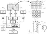
도 1은 본 발명의 일실시예에 따라 동적 아이박스 위치 조정을 포함하는 근안 디스플레이 시스템(100)을 도시한다. 도시된 예에서, 근안 디스플레이 시스템(100)은 컴퓨팅 디스플레이 서브 시스템(102), 렌더링 컴포넌트(104), 그리고 사용자의 좌안을 추적하기 위한 눈 추적 컴포넌트(106) 및 사용자의 우안을 추적하기 위한 눈 추적 컴포넌트(108)와 같은 하나 이상의 눈 추적 컴포넌트들을 포함한다. 컴퓨팅 디스플레이 서브 시스템(102)은 장치(114)에 장착된 좌안 디스플레이(110) 및 우안 디스플레이(112)를 포함하며, 상기 장치(114)는 사용자의 좌안 및 우안 앞에 상기 디스플레이들(110, 112)을 각각 배치한다.1 illustrates a near-
뷰(116)에 의해 도시된 바와 같이, 각각의 디스플레이(110, 112)는 근안 광필드 프레임들(이하, 용이한 참조를 위해 "광필드 프레임" 이라 함)의 시퀀스 또는 연속을 디스플레이하기 위한 적어도 하나의 디스플레이 패널(118)을 포함하고, 이들 각각은 요소 이미지들(122)의 어레이(120)를 포함한다. 설명의 용이성을 위해, 요소 이미지들(122)의 어레이(120)는 본 명세서에서 광필드 프레임(120)으로 지칭될 수도 있다. 또한, 각각의 디스플레이(110, 112)는 디스플레이 패널(118) 위에 놓이는 렌즈릿(126)(통상적으로, "마이크로 렌즈"로 지칭될 수도 있음)의 어레이(124)를 포함한다. 통상적으로, 렌즈릿 어레이(124)에 있는 렌즈릿들(126)의 개수는 어레이(120)에 있는 요소 이미지들(122)의 개수와 동일하지만, 다른 실시예에서 렌즈릿들(126)의 개수는 요소 이미지들(122)의 개수보다 더 많거나 더 적을 수 있다. 다음을 유의해야 하는바, 비록 도 1의 일례는 예시를 용이하게 하기 위해 요소 이미지들(122)의 5x4 어레이 및 이에 대응하는 렌즈릿들(126)의 5x4 어레이(120)를 도시하고 있지만, 전형적인 구현예에서, 광필드 프레임(120) 내의 요소 이미지들(122)의 개수 및 렌즈릿 어레이(124)에 있는 렌즈릿들(126)의 개수 일반적으로 훨씬 더 많다. 또한, 일부 실시예에서, 각각의 디스플레이(110, 112)에 대해 개별 디스플레이 패널(118)이 구현되는 반면에, 다른 실시예에서 좌안 디스플레이(110) 및 우안 디스플레이(112)는 하나의 디스플레이 패널(118)을 공유하며, 여기서 디스플레이 패널(118)의 좌측 절반은 좌안 디스플레이(110)를 위해 이용되고, 디스플레이 패널(118)의 우측 절반은 우안 디스플레이(112)를 위해 이용된다.As shown by
도 1의 단면도(128)는 디스플레이 패널(118) 위에 놓이는 렌즈릿 어레이(124)의 A-A 선을 따른 단면도로서, 렌즈릿 어레이(124)는 디스플레이 패널(118)의 디스플레이 표면(130) 위에 놓이며, 따라서 사용자의 눈(132)과 디스플레이 표면(130) 사이에 배치된다. 이러한 구성에서, 각각의 렌즈릿(126)은 디스플레이 표면(130)의 대응 영역을 눈의 동공(134)에 포커싱하며, 이러한 각각의 영역은 하나 이상의 인접 영역과 적어도 부분적으로 중첩된다. 따라서, 이러한 컴퓨팅 디스플레이 구성에서, 요소 이미지(122)의 어레이(120)가 디스플레이 패널(118)의 디스플레이 표면(130)에 디스플레이되고, 렌즈릿 어레이(124)를 통해 눈(132)에 의해 보여질 때, 사용자는 요소 이미지들(122)의 어레이(120)를 장면에 대한 단일 이미지로서 인식한다. 따라서, 이러한 프로세스가 사용자의 좌안 및 우안 둘다에 대해 이들 사이에 구현된 적절한 시차(parallax)를 통해 병렬로 수행되면, 결과적으로 상대적으로 넓은 FOV 및 이러한 컴퓨팅 디스플레이에 의해 종종 제공되는 얕은 폼 팩터((shallow formfactor)를 갖는 오토스테레오스코픽 3 차원(3D) 이미지가 사용자에게 제시된다.
또한, 도 1에 도시된 바와 같이, 렌더링 컴포넌트(104)는 도시된 중앙 처리 유닛(CPU)(136)과 그래픽 처리 유닛(GPU)(138, 140)와 같은 하나 이상의 프로세서들의 세트 및 시스템 메모리(142)와 같은 하나 이상의 저장 컴포넌트를 포함한다. 시스템 메모리(142)는 프로세서(136, 138, 140)에 의해 액세스되고 실행되는 소프트웨어 프로그램 또는 다른 실행가능 명령을 저장하여 여기에 기술된 바와 같은 다양한 작업을 수행하기 위해 프로세서(136, 138, 140) 중 하나 이상을 조작한다. 이러한 소프트웨어 프로그램은, 예를 들어, 아래에 설명되는 바와 같이, 광필드 프레임 렌더링 프로세스를 위한 실행가능한 명령을 포함하는 렌더링 프로그램(144) 뿐만 아니라, 아래에 설명되는 바와 같이, 눈 추적 프로세스를 위한 실행가능한 명령을 포함하는 눈 추적 프로그램(146)을 포함한다.Also, as shown in FIG. 1 ,
동작시에, 렌더링 컴포넌트(104)는 로컬 또는 원격 컨텐츠 소스(160)로부터 렌더링 정보(148)를 수신하며, 여기서 렌더링 정보(148)는 렌더링되고 디스플레이 서브 시스템(102)에 디스플레이될 이미지의 대상인 객체 또는 장면을 나타내는 그래픽 데이터, 비디오 데이터 또는 다른 데이터를 나타낸다. 렌더링 프로그램(144)을 실행하면, CPU(136)는 렌더링 정보(148)를 사용하여 드로잉 명령을 GPU(138, 140)에 전송하고, GPU(138, 140)는 드로잉 명령을 이용하여 좌안 디스플레이(110)에 디스플레이하기 위한 일련의 광필드 프레임들(151) 및 우안 디스플레이(112)에 디스플레이하기 위한 일련의 광필드 프레임들(153)을 병렬로 렌더링한다(공지된 다양한 VR/AR 계산/광필드 렌더링 프로세스들 중 임의의 것을 사용하여). 이러한 렌더링 프로세스의 일부로서, CPU(136)는 디스플레이 서브 시스템(102)의 포즈를 나타내는 포즈 정보(150)를 관성 관리 유닛(inertial management unit: IMU)(154)으로부터 수신할 수 있고, 상기 포즈로부터 물체 또는 장면의 시점을 반영하도록 광필드 프레임(151, 153)의 하나 이상의 쌍들의 렌더링을 제어할 수 있다.In operation, the
아래에 상세히 설명되는 바와 같이, 렌더링 컴포넌트(104)는 눈 추적 컴포넌트(106, 108) 중 하나 또는 둘다로부터의 눈 포즈 정보를 또한 사용하여, 디스플레이될 광필드 프레임 내에서 요소 이미지들(122)의 어레이(120)의 위치를 시프트하거나, 또는 디스플레이될 광필드 프레임의 요소 이미지들(122)의 사이즈를 스케일링할 수 있으며, 따라서 광필드 프레임이 이렇게 디스플레이되도록 아이박스의 위치를 효과적으로 시프트시킬 수 있다. 이를 위해, 눈 추적 컴포넌트(106, 108) 각각은 적외선(IR) 광으로 대응하는 눈을 조사하기 위한 하나 이상의 적외선(IR) 광 소스들(여기서는 "IR 조명기"로 지칭됨), 대응하는 눈으로부터 반사된 IR 광을 해당 눈 이미지(눈 이미지 정보 156)로서 캡처하는 하나 이상의 이미지 카메라, 반사된 IR 광을 이미지 카메라로 지향시키기 위한 하나 이상의 미러들, 도파관, 빔 스플리터, 등등 그리고 캡처된 눈 이미지로부터 대응하는 눈의 현재 위치, 현재 방향, 또는 이들 둘다(본 명세서에서 "포즈(pose)"로 단일 또는 집합적으로 지칭됨)를 결정하도록 눈 추적 프로그램(146)을 실행하도록 구성된 하나 이상의 프로세서들을 포함할 수 있다. 공지된 다양한 눈 추적 장치들 및 기법들 중 임의의 것이 사용자의 눈을 추적하는 눈 추적 컴포넌트(106),(108)로서 이용될 수 있으며, 그 일례가 아래의 도 5를 참조하여 설명된다. 대안적으로는, 개선된 성능을 갖는 눈 추적 컴포넌트들(106, 108)의 광학 컴포넌트들에 대한 예시적인 구성이 도 6-10을 참조하여 아래에 설명된다.As will be described in detail below, the
적어도 하나의 실시예에서, 근안 디스플레이 시스템(100)은 눈 포즈를 과거의 눈 포즈, 현재 눈 포즈, 또는 예측된(미래) 눈 포즈, 또는 이들의 조합으로 결정할 수 있다. 특히, 미래의 눈 포즈에 대한 예측은 개선된 성능 또는 개선된 응답 시간을 제공할 수 있고, 미래의 눈 포즈를 예측하기 위해 임의의 다양한 눈 움직임 예측 알고리즘이 구현될 수 있다. 또한, 일부 예에서, 눈 추적 컴포넌트(106, 108)는 눈 포즈 계산을 위해 사용자의 눈의 미래 시선을 예측하는 입력으로서 장면 정보(예를 들어, 렌더링될 이미지 내의 얼굴의 위치 또는 돌출 휴리스틱스(saliency Heuristic))를 이용할 수 있다. 이와 같이, 본원에 사용된 용어 "눈 포즈"는 과거, 현재 또는 예측된 눈 포즈 또는 이들의 일부 조합을 지칭할 수 있다.In at least one embodiment, the near-
통상적인 컴퓨팅 디스플레이-기반 근안 시스템에서, 각각의 요소 이미지가 디스플레이 패널에 디스플레이되는 위치는 고정되어 있다(즉, 요소 이미지들의 어레이의 위치는 고정되며 그리고 디스플레이되는 각각의 광필드 프레임에 대해서도 같다). 결과적으로 컴퓨팅 디스플레이에 대한 대응하는 아이박스의 위치도 고정될 것이다. 따라서, 사용자의 눈의 위치 또는 방향이 이러하 고정된 아이박스의 경계를 벗어나면, 디스플레이된 이미지에 대한 사용자의 지각은 가령, 이미지의 클리핑(clipping) 또는 비네팅(vignetting)을 통해 또는 초점 손실을 통해 종종 영향을 받는다.In a typical computing display-based near-eye system, the position at which each elemental image is displayed on the display panel is fixed (ie, the position of the array of elemental images is fixed and the same for each lightfield frame being displayed). As a result, the position of the corresponding eyebox relative to the computing display will also be fixed. Thus, if the position or orientation of the user's eyes is outside the bounds of this fixed eyebox, the user's perception of the displayed image may result in loss of focus or through clipping or vignetting of the image, for example. are often affected by
본 명세서에 설명된 바와 같이, 적어도 하나의 실시예에서 근안 디스플레이 시스템(100)은 사용자의 눈의 포즈와 보다 밀접하게 정렬하도록 아이박스의 위치를 효과적으로 "시프팅(shifting)"함으로써, 비 최적의 사용자 눈 포즈가 아이박스 제약에 미치는 영향을 완화시킨다. 이것은 디스플레이될 대응 광필드 프레임에 대하여 하나의 눈 또는 2개의 눈들의 포즈를 결정하도록 사용자의 하나 또는 양쪽 눈을 추적하는 눈 추적 컴포넌트(106, 108)를 사용함으로써 성취된다. 포즈가 결정되면, 대응 디스플레이 패널(118)에 디스플레이될 때, 렌더링 컴포넌트(104)는 렌더링되는 광필드 프레임 내의 요소 이미지들(122)의 위치를 디폴트 위치에 대해 대응하는 방향으로 시프트시킨다. 디스플레이 패널(118)의 디스플레이 표면(130)에 대한 요소 이미지들(122)의 어레이(120)의 위치에서의 이러한 시프트는, 렌즈릿 어레이(124)에 대하여 어레이(120)의 시야각을 이동시키는 효과를 가지므로, 아이박스의 위치를 시프트시키는 효과를 갖는다. 요소 이미지들의 위치들을 시프트시키는 대신에 또는 이에 부가하여, 렌더링 컴포넌트(104)는 사용자 눈의 포즈의 Z-축 컴포넌트에 응답하여 광필드 프레임 내의 요소 이미지들(122)의 치수들을 스케일링할 수 있으며, 따라서 눈 포즈의 Z 위치에 관계없이 가상 평면에서 표현된 이미지의 일정한 사이즈를 유지하려고 시도할 수 있다. 이러한 방식으로, 아이박스의 위치는 사용자의 눈의 포즈를 더욱 잘 수용하도록 동적으로 조정될 수 있다.As described herein, in at least one embodiment the near-
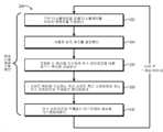
도 2는 일부 실시예에 따라 동적 아이박스 위치 조정을 제공하기 위해 조절된 포지셔닝을 갖는 광필드 프레임을 렌더링하기 위한 근안 디스플레이 시스템(100)의 동작 방법(200)을 도시한다. 이해를 용이하게 하기 위해, 방법(200)은 도 3에 도시된 예시적인 시나리오를 빈번하게 참조하여 아래에 설명된다. 방법(200)은 좌안 디스플레이(110) 또는 우안 디스플레이 중 하나에 대해 광필드 프레임을 렌더링 및 디스플레이하는 프로세스의 하나의 이터레이션을 예시하며, 따라서, 도시된 프로세스는 각각의 디스플레이(110, 112)에 대해 병렬로 반복적으로 수행되어, 상이한 시점에서 각각의 눈에 대해 광필드 프레임들의 상이한 스트림 또는 시퀀스를 생성 및 디스플레이하고, 따라서 3D, 오토스테레오스코픽 VR 또는 AR 경험을 사용자에게 제공할 수 있다.2 illustrates a
광필드 프레임이 생성 및 디스플레이되기 위해, 방법(200)은 블록(202)에서 시작하여, 렌더링 컴포넌트(104)는 사용자의 대응하는 눈에 디스플레이될 이미지 컨텐츠를 광필드 프레임으로서 식별한다. 적어도 하나의 실시예에서, 렌더링 컴포넌트(104)는 자이로스코프, 가속도계, 자력계, GPS(Global Positioning System) 센서 등과 같은 다양한 포즈 관련 센서들로부터의 데이터를 나타내는 IMU 정보(152)를 수신하며, 그리고 사용자의 눈 근처에 디스플레이(110, 112)를 장착하는데 사용된 장치(114)(예를 들어, HMD)의 포즈를 IMU 정보로부터 결정한다. 이 포즈로부터, 렌더링 프로그램(144)을 실행하는 CPU(136)는 대상 장면 또는 객체의 대응하는 현재 시점을 결정할 수 있고, 이러한 시점 및 렌더링 정보(148)로서 제공되는 장면 또는 객체의 그래픽적 및 공간적 설명으로부터, 렌더링될 이미지를 상기 포즈에 대해 결정할 수 있다.For the lightfield frame to be generated and displayed, the
블록(204)에서, 눈 추적 프로그램(146)을 실행하는 CPU(136)는 사용자의 대응하는 눈의 포즈를 결정한다. 여기에 설명된 바와 같이, 눈의 포즈는 다양한 눈 추적 기술 중 임의의 것을 사용하여 결정될 수 있다. 일반적으로, 이러한 기술은 눈의 동공 및 각막으로부터 반사된 하나 이상의 IR 광 이미지를 캡처하는 것을 포함한다. 눈 추적 프로그램(146)은 이미지를 분석하도록 CPU(136) 또는 GPU(138, 140)를 조작하여, 동공 반사 또는 각막 반사 중 하나 또는 둘 모두의 대응하는 위치에 기초하여 눈의 포즈를 결정할 수 있다. 또한, 각막에 대한 동공의 방향을 이용하여 눈의 방향(즉, 눈의 시선 방향)을 결정할 수 있다. 블록(204)이 블록(202)에 후속하는 것으로 도 2에 도시되어 있지만, 블록(204)의 프로세스는 블록(202)의 프로세스 이전, 도중 또는 이후에 수행될 수 있음에 유의해야 한다.At
사용자의 눈의 포즈가 결정되면, 블록(206)에서 렌더링 프로그램(144)은 사용자의 눈의 포즈에 기초하여 CPU(136)를 조작하여, 본 명세서에서 "SV_ELEM"으로 표기되는 시프트 벡터를 결정한다. 전술한 바와 같이, 시프트 벡터(SV_ELEM)는 사용자의 눈의 포즈에서의 대응하는 시프트를 보상하기 위해, 렌더링될 광필드 프레임 내의 요소 이미지들에 적용될 위치에 대한 시프트를 나타낸다. 특히, 시프트 벡터에 의해 표현되는 보상 시프트는 아이박스에 의해 표현된 영역에서 눈이 상대적으로 중심에 위치되도록, 사실상 그 포즈에서 눈 주위에 컴퓨팅 디스플레이의 아이박스를 위치시키도록 의도된다. 즉, 시프트 벡터는 눈의 포즈에 맞게 아이박스를 동적으로 시프트시키는 역할을 한다.Once the user's eye pose is determined, in
적어도 하나의 실시예에서, 시프트 벡터(SV_ELEM)의 계산은 사용자의 눈의 디폴트 포즈 및 디스플레이 표면(130)에 대한 요소 이미지들(122)의 어레이(120)에 대한 대응하는 디폴트 위치의 가정 또는 특정에 기초한다. 이를 설명하기 위하여, 도 3의 단면도(300)에 의해 예시된 예시적인 시나리오를 참조하면, 대응하는 디스플레이 패널(118)에 대한 사용자의 눈(304)의 디폴트 포즈(302)는 디스플레이 표면(130)에 대한 X-Y 평면에서 중앙에 위치하고(즉, 눈(304)의 시야축이 디스플레이 표면(130)의 중심축(306)과 정렬됨) 그리고 디스플레이 표면(130) 또는 렌즈릿 어레이(124)로부터의 Z- 축을 따라 가정된 거리 또는 디폴트 거리에 위치되도록 설정 또는 정의될 수 있다. 이러한 디폴트 포즈(302)에 있는 눈(304)의 경우, 광필드 프레임의 요소 이미지들(122)의 어레이(120)에 대한 디폴트 위치는 마찬가지로 디스플레이 표면(130)에 대해 중심에 위치하도록 정의될 수 있다. 예시를 위해, 단면도(300)에서, 광필드 프레임은 요소 이미지들의 3x3 어레이로 구성되며, 따라서 단면도(300)에 존재하는 3개의 요소 이미지들은 디스플레이 패널(118)의 영역들(308, 309, 310)로 표시되고, 이들 영역들(308, 309, 310)은 눈(304)이 디폴트 포즈(302)에 있을 때(이 일례에서는, 렌즈릿 어레이(124)로부터 소정 거리에서 축(306)을 따라 중심에 위치될 때), 중심 축(306)을 중심으로 가운데에 위치하는 예시된 디폴트 위치(312)를 갖는다.In at least one embodiment, the calculation of the shift vector SV_ELEM assumes or specifies a default pose of the user's eye and a corresponding default position relative to the
3x3 요소 이미지 구성(및 대응하는 3x3 렌즈릿 어레이 구성)을 갖는 본 일례에서, 대응하는 아이박스는 수직선(314)으로 표시되는 바와 같이 디스플레이 표면(130)에 평행한 평면에서 치수를 갖는다. 즉, 디스플레이 표면(130)으로부터 동일한 거리에서 눈(304)이 포즈(316)와 포즈(318) 사이에 위치되는 한, 사용자는 영역(309)에 디스플레이되는 요소 이미지에 대한 언클리핑된(unclipped) 시야 또는 비폐색(non-occluded) 시야를 가져야만 한다. 하지만, 도 3에 도시된 예시적인 시나리오는 디스플레이 패널(118)에 대한 아이박스의 사이즈를 과장한 것이다. 훨씬 더 많은 개수의 요소 이미지들, 훨씬 더 많은 개수의 렌즈릿들, 그리고 디스플레이 패널로부터 훨씬 더 긴 거리에 위치한 눈, 등을 갖는 전형적인 구성에서, 아이박스는 디스플레이 패널(118)에 비해 훨씬 더 작을 것이다. 따라서, 디폴트 IPD(inter-pupillary distance) 범위로부터 사용자 IPD가 약간만 움직이거나 또는 이탈하더라도, 사용자의 눈이 아이박스 외곽에 속할 수 있으며, 따라서 디스플레이되는 광필드 프레임의 사용자의 시야에 영향을 미칠 수 있다.In this example with a 3x3 elemental image configuration (and a corresponding 3x3 lenslet array configuration), the corresponding eyebox is dimensioned in a plane parallel to the
눈(304)에 대한 이러한 디폴트 포즈(302) 및 그렇게 정의되거나 달리 설정되는 광필드 프레임에 대한 대응하는 디폴트 위치(312)를 사용하여, 렌더링 컴포넌트(104)는 눈(304)의 포즈에 의해 표시되는 디폴트 포즈(302)로부터의 변화에 기초하여, 디폴트 위치(312)에 대한 시프트 벡터(SV_ELEM)를 결정할 수 있다. 예시를 위해, 단면도(300)는 예시적인 시나리오를 도시하며, 여기서 눈 추적 컴포넌트(106)는 눈(304)을 추적하고 그리고 블록(204)에서, 그것의 포즈가 위치(320)에 있음을 결정하는바, 이는 중심축(306)을 중심으로 가운데에 위치한 디폴트 포즈(302)로부터 위쪽으로 시프트됨을 나타낸다(이 시프트는 화살표(322)로 표시됨). 눈(304)의 위치에서의 이러한 상향 시프트를 보상하기 위해, 블록(206)에서, 렌더링 컴포넌트(104)는 반대 방향으로, 즉, 도 3의 방향에서 아래 방향으로 보상 시프트 벡터(SV_ELEM)(화살표(324)로 표시)를 결정한다.Using this default pose 302 for the
적어도 하나의 실시예에서, 렌더링 컴포넌트(104)는 다음의 표현에 기초하여 시프트 벡터 SV_ELEM을 결정한다:In at least one embodiment, the

여기서 SV_ELEM은 시프트 벡터를 나타내고, EYE_SHIFT는 눈 포즈 시프트를 벡터 형태로 나타내고, F_A는 렌즈릿(126)의 초점 길이(즉, 디스플레이 표면(130)와 렌즈릿(126)의 평면 사이의 거리)를 나타내고, D_ER은 아이 릴리프(eye relief)(즉, 렌즈릿(126)의 평면과 눈(304) 사이의 거리)를 나타낸다. 다음을 유의해야 하는바, 눈(304)이 디폴트 포즈에 놓여지는 경우, EYE_SHIFT 항은 0이 될 것이고, 따라서 시프트 벡터 SV_ELEM도 마찬가지로 0이 될 것이다(즉, 시프트 없음). 상기 설명은 모든 요소 이미지가 동일한 정도 또는 양만큼 시프트되는 구현예에 관한 것이지만, 다른 구현예에서 요소 이미지의 위치 시프트는 요소 이미지마다 다를 수 있다. 가령, 상이한 원근 시프트들(예를 들어, 시차 시프트)를 수용하기 위해, 상이한 요소 이미지들은 상이한 위치 시프트들을 가질 수 있다.where SV_ELEM denotes the shift vector, EYE_SHIFT denotes the eye pose shift in vector form, and F_A denotes the focal length of the lenslet 126 (i.e., the distance between the
일부 경우에, 디폴트 포즈로부터의 눈 포즈의 시프트는 Z- 방향으로의 시프트를 포함할 수 있다. 그러한 경우, 블록(206)에서, 렌더링 컴포넌트(104)는 렌더링될 광필드 프레임의 요소 이미지들에 적용할 스케일링(또는 배율)의 양을 결정한다. 예시하기 위해, x 차원(x = X 또는 Y)으로 렌더링될 요소 이미지의 사이즈를 나타내는 x_elem은 다음 표현에 의해 결정될 수 있다.In some cases, shifting the eye pose from the default pose may include a shift in the Z-direction. If so, at

도 2를 다시 참조하면, 시프트 벡터(SV_ELEM)가 결정되고 요소 이미지의 스케일링이 적절하게 결정되면, 블록(208)에서 렌더링 프로그램(144)은 CPU(136)를 조작하여 GPU(138, 140) 중 대응하는 하나는 블록(202)에서 식별된 이미지 콘텐츠를 사용하는 어레이(120)로 광필드 프레임을 렌더링하도록 지시하며, 광필드 프레임은 요소 이미지의 어레이를 포함한다. 이 프로세스의 일부로서, CPU(136)는 시프트 벡터(SV_ELEM) 및 요소 이미지들의 치수들에 적용될 스케일링에 대한 표시를 GPU에 제공하고, 광필드 프레임을 렌더링하도록 GPU에 지시하는바, 따라서 요소 이미지들은 시프트 벡터(SV_ELEM)에 의해 프레임 내에서 그들의 디폴트 위치들에 대하여 시프트되며 그리고 제공된 스케일링 정보에 따라 스케일링된다. 결과적으로, GPU는 시프트된 및/또는 스케일링된 요소 이미지들의 어레이로 광필드 프레임을 렌더링하고, 블록(210)에서 GPU는 사용자의 눈(304)에 디스플레이하기 위해 광필드 프레임을 컴퓨팅 디스플레이(110, 112) 중 대응하는 하나에 제공한다.Referring back to FIG. 2 , once the shift vector SV_ELEM has been determined and the scaling of the element image has been determined appropriately, in
도 3으로 다시 돌아가서, GPU가 화살표(324)로 표현된 시프트 벡터 SV_ELEM을 구현할 때, 결과적인 요소 이미지들의 어레이는 프레임 또는 디스플레이 표면(130)에 대해 아래쪽으로 시프트되어 시프트된 위치(326)에 있게되며, 따라서 단면도(300)에 도시된 3개의 요소 이미지들은 시프트된 부분들(308' , 309' 및 310')에서 디스플레이된다. 결과적인 아이박스(수직선(328)으로 표시됨)는 디폴트 포즈(302)에서 제시된 아이박스에 대해 효과적으로 상향으로 시프트되며, 따라서 이것은 일반적으로 눈(304)의 포즈(320)에 중심을 두게되며, 따라서 디스플레이된 이미지의 비네팅 또는 다른 불명료(obfuscation) 없이, 눈(304)이 포즈(330)와 포즈(332) 사이에서 임의의 곳으로 움직일 수 있게 한다. 포즈(330)가 오리지널 아이박스 외부에 있음을 주목하면서, 디스플레이된 광필드 프레임의 요소 이미지들의 상보적 시프트를 통한 아이박스의 이러한 동적 시프트는, 고정된 아이박스로 성취할 수 있는 것보다, 눈 위치 및 방향에 있어서 훨씬 더 큰 변동을 허용할 수 있다.3 , when the GPU implements the shift vector SV_ELEM represented by
도 4는 일부 실시예에 따라 동적 아이박스 시프팅을 용이하게하기 위해, 디스플레이된 광필드의 요소 이미지들에 대한 추가적인 상보적 시프팅을 도시한다. 뷰(402)에 의해 도시된 바와 같이, 눈(404)의 포즈는 디스플레이 패널(118)에 대한 디폴트 포즈에 있고 따라서 요소 이미지(408)의 어레이(406)는 광필드 프레임 내의 디폴트 위치에 렌더링된다. 그러나, 뷰(410)에 의해 도시된 바와 같이, 눈(404)의 포즈가 디폴트 포즈의 오른쪽으로 이동하게 되면, 어레이(406)의 위치가 광필드 프레임 내의 디폴트 위치의 왼쪽으로 상보적으로 시프트된다. 마찬가지로, 뷰(412)에 의해 도시된 바와 같이, 눈(404)의 포즈가 상향으로 이동하게 되면 광필드 프레임 내의 디폴트 위치로부터 어레이(406)에 대한 아래 방향으로의 상보적 시프트가 야기된다. 눈(304)의 포즈에서의 시프트는 하나의 기본(cardinal) 방향으로의 변화로 제한되지 않으며, 어레이(406)의 위치에서의 대응하는 시프트도 제한되지 않는다. 예를 들어, 뷰(414)는 디폴트 포즈로부터 우측 아래 방향으로의 눈의 포즈의 시프트는 광필드 프레임 내에서 상향 및 좌측으로의 어레이(460) 위치의 상보적인 시프트를 야기함을 보여준다. 어레이(406)의 위치들에서의 이러한 시프트들은 또한, Z 축을 따른 디폴트 위치로부터 눈(404)의 시프트들에 응답하여, 어레이 내의 요소 이미지들(408)의 확대 또는 다른 스케일링을 동반할 수 있다.4 illustrates an additional complementary shifting of elemental images of a displayed lightfield to facilitate dynamic eyebox shifting in accordance with some embodiments. As shown by
설명된 동적 아이박스 프로세스는 사용자의 눈의 포즈에 따라 근안 광필드 프레임 내에서 요소 이미지들의 어레이(120)에 대한 시프팅을 야기하기 때문에, 전형적으로 근안 광필드 프레임은, 요소 이미지들의 클리핑(clipping) 없이, 다양한 임의의 방향으로 어레이(120)의 위치가 시프트될 수 있게 하기 위하여, 그것의 디폴트 혹은 중심 위치에서 어레이(120)를 둘러싸는 작은 버퍼 구역을 이용한다는 점에 유의해야 한다. 전형적으로, 이러한 버퍼 구역은 렌즈릿(126)의 확대 텀(magnification term)을 고려하면 비교적 완만하며, 그리고 일반적으로 전체 디스플레이 표면(130)의 매우 작은 부분만을 차지한다. 대안적으로, 다른 실시예들에서, 버퍼 구역이 배제될 수 있으며 그리고 어레이(120)의 위치에서의 시프트가 구현될 때 리딩 에지 상의 요소 이미지들은 클리핑되도록 허용될 수 있다.Because the described dynamic eyebox process causes shifting of the
또한, 눈의 방향에서의 변화는 눈의 위치의 변화에 부가하여 또는 이를 대신하여, 요소 이미지의 위치에서 대응하는 시프트를 유발할 수 있다. 본 명세서에서 고려되는 근안 광필드 디스플레이의 유형들은 전형적으로 시선 방향에 둔감하기 때문에, 눈 위치의 변화와 관련하여 본 명세서에 설명된 것과 동일한 방식으로 눈 방향의 변화들이 처리될 수 있다. 즉, 본 명세서에 설명된 동적 아이박스 시프팅 프로세스는 눈 포즈의 임의의 양상(즉, 눈 방향, 눈 위치 또는 이들의 조합)에 효과적으로 적용될 수 있다.Also, a change in the direction of the eye may cause a corresponding shift in the position of the elemental image in addition to or instead of a change in the position of the eye. Since the types of near-eye lightfield displays contemplated herein are typically insensitive to gaze direction, changes in eye direction may be handled in the same manner as described herein with respect to changes in eye position. That is, the dynamic eyebox shifting process described herein can be effectively applied to any aspect of eye pose (ie, eye direction, eye position, or a combination thereof).
전술한 바와 같이, 본 명세서에 설명된 동적 아이박스 시프팅 프로세스는 대응하는 눈의 포즈를 결정하기 위해 눈 추적 컴포넌트(예를 들어, 눈 추적 컴포넌트 106, 108)를 이용한다. 이러한 눈 추적 컴포넌트는 일반적으로 눈을 조명하기 위한 하나 이상의 IR 조명기, 눈으로부터의 IR 반사 이미지를 캡처하기 위한 이미징 카메라, 하나 이상의 렌즈, 도파관 또는 눈으로부터 반사된 IR 광을 이미징 카메라로 안내하기 위한 다른 광학 요소들 및 캡처된 이미지를 분석하기 위해 소프트웨어 프로그램을 실행하는 하나 이상의 프로세서를 포함한다.As noted above, the dynamic eyebox shifting process described herein uses eye tracking components (eg,
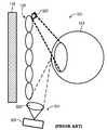
도 5는 근안 디스플레이 시스템(100)에서 눈 추적 컴포넌트로서 이용될 수 있는 눈 추적 컴포넌트의 광학 컴포넌트들에 대한 통상적인 구성을 도시한다. 단면도(500)에 의해 예시된 바와 같이, 이러한 통상적인 접근법에서 IR 조명기(502)는 렌즈릿 어레이(124)의 일측 단부에서 대응하는 렌즈릿 어레이(124)에 또는 그 근처에 배치되는 반면에, 이미징 카메라(506) 및 하나 이상의 렌즈들(508)을 포함하는 이미지 캡처 어셈블리(504) 또는 다른 광학 요소들은 렌즈릿 어레이(124)의 타측 단부에 배치되며, 따라서 IR 조명기(502)와 이미지 캡쳐 어셈블리(504)는 렌즈릿 어레이(124)를 통해 볼 때 디스플레이 패널(118)에 대해 눈(510)의 FOV 내에 있지 않으며 따라서, 디스플레이 패널(118)의 시청을 방해하지 않는다. 동작시에, IR 조명기(502)는 IR 광으로 눈(510)을 조명하고, 그리고 눈(510)으로부터 반사된 IR 광은 이미지 캡처 어셈블리(504)에 의해 하나 이상의 이미지로서 캡처된다. 그러나, 이미지 캡처 어셈블리(504)의 위치는 이미지 캡쳐 어셈블리(504)가 눈(510) 및 IR 반사에 대해 비스듬한 각도로 놓이게하는바, 이는 이와 같이 캡쳐된 임의의 이미지들의 눈 추적 분석에 대해 문제를 야기할 수 있다. 이러한 문제에 대한 전형적인 해결책들 중 하나는 비스듬한 각도를 감소시키기 위해 최소한의 아이 릴리프를 부과하는 것이지만, 이는 그렇지 않은 경우에 필요한 것보다 더 두꺼운 폼 팩터를 초래하여, 디스플레이 시스템에 대한 사용자의 즐거움을 감소시킬 수 있다.5 shows a typical configuration for the optical components of an eye tracking component that may be used as an eye tracking component in the near
도 6은 일부 실시예에 따라 근안 디스플레이 시스템(100)에 이용될 수 있는 눈 추적 컴포넌트의 광학 컴포넌트에 대한 개선된 구성을 도시한다. 도 6의 단면도(600)에 의해 도시된 바와 같이, 이 구성에서는 IR 조명기(602, 604)와 같은 하나 이상의 IR 조명기가 렌즈릿 어레이(124)의 렌즈릿들(126) 사이에 배치되므로, 이로부터 방출된 IR 광이 덜 비스듬한 각도에서 눈(610)으로 떨어진다. 또한, 눈(610)으로부터 직접 반사된 IR 광을 포착하려고 시도하는 대신에, 도 6의 구성은 렌즈릿 어레이(125)와 디스플레이 패널(118) 사이에 배치된 평면형 또는 곡선형 반사 요소(608)(이는 IR 반사기/거울 또는 빔 스플리터를 포함할 수 있다)를 사용한다. 이미징 카메라(614) 및 하나 이상의 렌즈들(616) 또는 다른 광학 요소를 포함하는 이미지 캡처 어셈블리는(612)는 반사 요소(608)에 포커싱한다. 이러한 접근법에서, 눈(610)으로부터 반사된 IR 광은 렌즈릿 어레이(124)의 하나 이상의 인접한 렌즈릿(126)에 의해 반사 요소(608) 상에 포커싱되며, 반사 요소(608)는 이러한 입사 IR 광을 하나 이상의 이미지로서 캡처하기 위해 이미지 캡처 어셈블리(612)를 향해 반사시킨다. 결과적으로, 이러한 접근법에서, 이미징을 위해 캡처된 IR 광은 도 5에 도시된 종래의 구성에서 캡처된 것보다 덜 경사진 각도에서 획득되고, 따라서 이미지 캡처 어셈블리(612)를 사용자의 시야(vision) 주변에서 유지하면서도 보다 정확한 시선 추적을 용이하게 할 수 있다. 비록, 도 6의 일례에는 하나의 이미지 캡처 어셈블리(612)가 도시되어 있지만, 다른 실시예에서는 렌즈릿 어레이(124)의 주변부에 있는 다수의 이미지 캡처 어셈블리들이 사용되어, 개선된 눈 추적 정확도를 위해 상이한 관점(viewpoint)들에서 눈(610)의 반사된 IR 이미지를 캡처할 수 있음에 유의해야 한다.6 illustrates an improved configuration for the optical component of an eye tracking component that may be used with the near
반사 요소(608)가 눈(610)의 FOV 내에 있다는 것이 이해될 것이다. 그러나, 반사 요소(608)가 디스플레이 패널(118)과 렌즈릿 어레이(124) 사이에 배치되기 때문에(즉, 렌즈릿(126)의 초점 거리 보다 더 가까움), 반사 요소(608)는 눈(610)에 대한 초점에서 벗어나게 될 것이다. 그럼에도 불구하고, 반사 요소(608)는 반사 요소(608) 뒤에 배치된 하나 이상의 요소 이미지들에 대한 눈의 시야를 가릴 것이다. 하지만, 도 9를 참조하여 아래에 보다 상세히 설명된 바와 같이, 컴퓨팅 디스플레이가 사실상 중첩 프로젝터들의 어레이이기 때문에, 가려지지 않은(non-obscured) 중첩 프로젝터들의 강도가 가려진 요소 이미지(들)를 계산적으로 보상하는데 이용될 수 있다.It will be appreciated that the
도 7은 일부 실시예에 따라 근안 디스플레이 시스템(100)에서 이용될 수 있는 눈 추적 컴포넌트의 광학 컴포넌트들에 대한 다른 개선된 구성을 도시한다. 단면도(700)에 의해 도시된 바와 같이, 이러한 구성에서 IR 조명기(702, 704)와 같은 하나 이상의 IR 조명기는 렌즈릿 어레이(124)의 렌즈릿들(126) 사이에 위치되어 그로부터 방출된 IR 광이 덜 비스듬한 각도로 눈(710)에 떨어지도록 한다. 또한, 이미지 캡처를 위해 눈(710)으로부터 반사된 IR 광을 주변부로 재지향시키는 대신에, 도 7의 구성은 렌즈릿 어레이(124)와 디스플레이 패널(118) 사이에 이미지 캡처 어셈블리(706)를 배치하며, 이미징 카메라(708)와 하나 이상의 렌즈(712)들, 또는 다른 광학 소자를 포함하는 상기 이미지 캡처 어셈블리(706)는 눈(710)쪽으로 포커싱된다. 이러한 접근법에서, 눈(710)으로부터 반사된 IR 광은 렌즈릿 어레이(124)의 개재(intervening) 렌즈릿(126)에 의해서 직접적으로(즉, 반사없이) 이미징 카메라(708) 상에 포커싱되는바, 이미지 캡처 어셈블리의 하나 이상의 광학 요소들을 통해 포커싱된다. 따라서, 이 접근법에서 이미지 캡쳐 어셈블리(708)는 눈(710)의 동공 및 각막의 직접 또는 예각(acute angle) 뷰를 가지며, 이는 매우 정확한 눈 추적을 용이하게 한다. 하나의 이미지 캡처 어셈블리(706)가 도 7의 예에 도시되어 있지만, 다른 실시예에서는 렌즈릿 어레이(124)와 디스플레이 패널(118) 사이에 배치된 다수의 이미지 캡처 어셈블리(706)들이 눈 추적 정확도를 높이기 위해 상이한 관점(viewpoint)들로부터 눈(610)의 반사된 IR 이미지를 캡처하는데 사용될 수 있음에 유의해야 한다. 또한, 도 6의 구성에서와 같이, 이미징 카메라 어셈블리(706)의 존재는 눈(710)에 초점이 맞지 않지만, 이미징 카메라 어셈블리(706) 뒤에 있는 요소 이미지를 가릴 것이다. 하지만, 중첩하는 프로젝터 효과로 인하여, 하나 이상의 인접한 요소 이미지들의 적어도 일부분들의 광도는, 후술하는 바와 같이, 가려진 요소 이미지를 보상하도록 계산 방법을 통해 선택적으로 증가될 수 있다.7 illustrates another improved configuration for the optical components of an eye tracking component that may be used in the near
도 8은 도 7의 구성에 대한 수정예를 도시하는바, 단면도(800)로 도시된 바와 같이, 하나의 디스플레이 패널(118)을 채용하는 것이 아니라, 다수의 타일형(tiled) 디스플레이 패널들(818)이 이용되어, 효과적인 대형의 디스플레이 패널을 형성한다. 이러한 접근법에서, 이미징 카메라 어셈블리(706)가 디스플레이 패널들(818) 사이의 간격에 위치되도록 타일형 디스플레이 패널들(818)은 서로 분리되며, 따라서 이미징 카메라 어셈블리(706)가 눈(710)의 시야로부터 하나 이상의 요소 이미지들을 가리는 것을 방지할 수 있다.8 shows a modified example of the configuration of FIG. 7 , as shown in a
도 6 내지 도 8에 도시된 눈 추적 컴포넌트 구성들은 눈의 동공 및 각막의 덜 비스듬한 또는 보다 직접적인 관점(viewpoint)을 제공함으로써 개선된 눈 추적 정확도를 용이하게 할 수 있는 장점을 갖는다. 하지만, 이들 구성들은 또한 눈과 디스플레이 패널 사이에 요소들을 배치하고 있으며, 따라서 디스플레이 패널에 디스플레이되는 하나 이상의 요소 이미지들에 대한 눈의 시야를 가리게 된다. 렌더링 컴포넌트(104)는 본 명세서에서 고려되는 컴퓨팅 디스플레이와 같은 근안 광필드 디스플레이의 중첩 프로젝터 특성을 활용함으로써 하나 이상의 가려진 요소 이미지들을 보상할 수 있다.The eye tracking component configurations shown in FIGS. 6-8 have the advantage of facilitating improved eye tracking accuracy by providing a less oblique or more direct viewpoint of the eye's pupil and cornea. However, these configurations also place elements between the eye and the display panel, thus obscuring the eye's view of one or more element images displayed on the display panel.
예시하기 위해, 도 9는 근안 디스플레이 시스템(100)에서 이용되는 것들과 같은 컴퓨팅 디스플레이의 단면도(900)를 도시한다. 도 9에 도시된 바와 같이, 렌즈릿 어레이(124)의 각각의 렌즈릿(126)들은 눈(902) 상의 개별 "프로젝터" 로서 역할을 하며, 디스플레이 패널(118)에 디스플레이된 요소 이미지들의 어레이로부터 복합 가상 이미지(904)를 형성함에 있어서, 각각의 "프로젝터"는 하나 이상의 인접한 프로젝터들과 중첩한다. 예시하기 위해, 렌즈릿(126-1)은 대응하는 요소 이미지(영역 906으로 표시)를 가상 이미지(904)의 영역(914)에 투영하고, 렌즈릿(126-2)은 대응하는 요소 이미지(영역 907로 표시)를 가상 이미지(904)의 영역(915) 상에 투영하고, 그리고 렌즈릿(126-3)은 대응하는 요소 이미지(영역 908로 표시)를 가상 이미지(904)의 영역(916)에 투영한다. 또한, 도 9에 도시된 바와 같이, 영역들(914 및 915)은 하위 영역(917)에서 중첩되고, 영역들(915 및 916)은 하위 영역(918)에서 중첩되고, 3개의 영역들(914, 915, 916)은 하위 영역(919)에서 중첩된다.To illustrate, FIG. 9 shows a cross-sectional view 900 of a computing display, such as those used in the near-
따라서, 본 일례에서, 디스플레이 패널(118)의 영역(907)에 위치된 요소 이미지가 영역(907)과 렌즈릿 어레이(124) 사이에 배치된 이미지 캡처 장치로 인해 눈(902)으로부터 가려진다라고 가정하면, 하나 이상의 주변 요소 이미지들의 강도(intensity)가 계산적으로 증가되어, 영역(907)의 가려진 요소 이미지로 인해 야기되는 강도 손실을 보상할 수 있다. 예를 들어, 예시된 평면에서, 영역(906, 908)의 요소 이미지들은, 디스플레이 패널(118)의 다른 방향의 평면들에서의 요소 이미지들과 마찬가지로, 밝기가 증가될 수 있으며, 따라서 영역(907)에서의 가려진 요소 이미지를 계산적으로 보상할 수 있다. 도 9는 바로 인접한 요소 이미지만을 갖는 중첩 영역을 갖는 단순화된 예를 도시함을 유의해야 한다. 많은 구현들에서, 가려진 요소 이미지에 바로 인접한 것들 이외의 요소 이미지들은, 가려진 요소 이미지의 가려진 픽셀들과 중첩되는 픽셀 영역들을 가질 수 있다. 따라서, 일반적으로, 가려진 요소 이미지를 계산적으로 보상하는 것은, 가려진 요소 이미지의 어느 픽셀들이 주변 요소 이미지들에 복제되는지를 식별하는 것 그리고 주변 요소 이미지들 내의 복제된(즉, 중첩된) 픽셀들의 강도를 분수 (N + 1)/N 으로 스케일링하는 것을 포함하며, 여기서 N은 해당 픽셀을 공유하는 요소 이미지들의 개수를 나타낸다.Thus, in this example, it is said that an elemental image located in region 907 of
일부 실시예에서, 전술한 설명의 특정 양상들은 소프트웨어를 실행하는 프로세싱 시스템의 하나 이상의 프로세서에 의해 구현된다. 소프트웨어는 비일시적 컴퓨터 판독가능 저장 매체에 저장되거나 그렇지 않으면 유형적으로 구현된 하나 이상의 실행 가능 명령 세트를 포함한다. 소프트웨어는 하나 이상의 프로세서에 의해 실행될 때 하나 이상의 프로세서를 조작하여 전술한 설명의 하나 이상의 양상들을 수행하는 명령 및 특정 데이터를 포함할 수 있다. 비일시적 컴퓨터 판독가능 저장 매체는 예를 들어 자기 또는 광 디스크 저장 디바이스, 플래시 메모리와 같은 솔리드 스테이트 저장 디바이스, 캐시, 랜덤 액세스 메모리(RAM) 또는 다른 비휘발성 메모리 디바이스 등등을 포함할 수 있다. 비일시적 컴퓨터 판독가능 저장 매체에 저장된 실행 가능 명령은 소스 코드, 어셈블리 언어 코드, 객체 코드, 또는 하나 이상의 프로세서에 의해 해석되거나 달리 실행가능한 다른 명령 포맷일 수 있다.In some embodiments, certain aspects of the foregoing description are implemented by one or more processors of a processing system executing software. The software includes one or more sets of executable instructions stored in a non-transitory computer-readable storage medium or otherwise tangibly embodied. Software may include instructions and specific data that, when executed by one or more processors, operate the one or more processors to perform one or more aspects of the foregoing description. Non-transitory computer-readable storage media may include, for example, magnetic or optical disk storage devices, solid state storage devices such as flash memory, cache, random access memory (RAM) or other non-volatile memory devices, and the like. The executable instructions stored in the non-transitory computer-readable storage medium may be in source code, assembly language code, object code, or other instruction format that is interpreted or otherwise executable by one or more processors.
컴퓨터 판독 가능 저장 매체는 컴퓨터 시스템에 명령 및/또는 데이터를 제공하기 위해 사용 중에 컴퓨터 시스템에 의해 액세스 가능한 임의의 저장 매체, 또는 저장 매체의 조합을 포함할 수 있다. 이러한 저장 매체는 광학 매체(예를 들어, 콤팩트 디스크(CD), 디지털 다목적 디스크(DVD), 블루 레이 디스크), 자기 매체(예를 들어, 플로피 디스크, 자기 테이프 또는 자기 하드 드라이브), 휘발성 메모리(예를 들어, 랜덤 액세스 메모리(RAM) 또는 캐시), 비휘발성 메모리(예를 들어, ROM(read-only memory) 또는 플래시 메모리), 또는 MEMS(microelectromechanical systems) 기반 저장 매체를 포함할 수 있지만 이에 제한되지는 않는다. 컴퓨터 판독가능 저장 매체는 컴퓨팅 시스템 내에 내장될 수 있으며(예를 들어, 시스템 ROM 또는 RAM), 컴퓨팅 시스템에 고정식으로 부착될 수 있으며(예를 들어, 자기 하드 드라이브), 컴퓨팅 시스템에 착탈식으로 부착될 수 있으며(예를 들어, 광학 디스크 또는 USB-기반의 플래시 메모리), 또는 유/무선 네트워크를 통해 컴퓨팅 시스템에 접속될 수 있다(예를 들어, 네트워크 액세스가능 스토리지(NAS)).Computer-readable storage media may include any storage media, or combination of storage media, that are accessible by a computer system during use to provide instructions and/or data to the computer system. Such storage media may include optical media (eg, compact disc (CD), digital versatile disc (DVD), Blu-ray disc), magnetic media (eg, floppy disk, magnetic tape or magnetic hard drive), volatile memory (eg, may include, but are not limited to, random access memory (RAM) or cache), non-volatile memory (eg, read-only memory (ROM) or flash memory), or microelectromechanical systems (MEMS) based storage media. it doesn't happen A computer-readable storage medium may be embodied within the computing system (eg, system ROM or RAM), may be fixedly attached to the computing system (eg, a magnetic hard drive), and may be removably attached to the computing system. (eg, optical disk or USB-based flash memory), or connected to the computing system via a wired/wireless network (eg, network accessible storage (NAS)).
전술한 일반적인 설명 부분에서 상술된 모든 행동들 또는 요소들이 요구되는 것은 아니며, 특정 활동 또는 디바이스의 일부가 요구되지 않을 수 있으며, 설명된 것들 이외의 하나 이상의 추가 활동이 수행될 수 있거나, 또는 요소들이 추가될 수 있음에 유의해야 한다. 또한, 활동들이 나열된 순서가 반드시 수행되는 순서는 아니다. 또한, 개념들은 특정 실시예들을 참조하여 설명되었다. 그러나, 당업자는 이하의 청구 범위에 기재된 본 개시의 범위를 벗어나지 않고 다양한 수정 및 변경이 이루어질 수 있음을 이해할 것이다. 따라서, 명세서 및 도면은 제한적인 의미보다는 예시적인 의미로 간주되어야하고, 그러한 모든 수정은 본 개시의 범위 내에 포함되는 것으로 의도된다.Not all acts or elements recited in the foregoing general description are required, some specific activity or device may not be required, one or more additional activities other than those described may be performed, or elements may be Note that it can be added. Also, the order in which the activities are listed is not necessarily the order in which they are performed. Also, concepts have been described with reference to specific embodiments. However, it will be understood by those skilled in the art that various modifications and changes may be made without departing from the scope of the present disclosure as set forth in the claims below. Accordingly, the specification and drawings are to be regarded in an illustrative rather than a restrictive sense, and all such modifications are intended to be included within the scope of the present disclosure.
본 발명의 이점들, 다른 장점들 및 문제에 대한 해결책들이 특정 실시예와 관련하여 설명되었다. 하지만, 상기 이점들, 장점들, 문제에 대한 해결책들 및 임의의 이점, 장점, 해결책을 야기하거나 더욱 자명하게 만들 수 있는 임의의 피처(들)은 임의의 청구항 또는 모든 청구항들에서 중요하고, 필수적이고, 또는 본질적으로 피처로서 간주되어서는 안된다. 또한, 본 발명의 주제는 본 명세서의 교시의 이점을 갖는 당업자에게 명백하지만 상이한 방식으로 수정 및 실시될 수 있기 때문에, 위에서 개시된 특정 실시예는 단지 일례일 뿐이다. 이하의 청구 범위에 기재된 것 이외의 본 명세서에 도시된 구성 또는 설계의 세부 사항에 대한 제한은 없다. 따라서, 상기 개시된 특정 실시예는 변경되거나 수정될 수 있으며, 이러한 모든 변형은 개시된 주제의 범위 내에서 고려된다는 것이 명백하다. 따라서, 본 명세서에서 요구되는 보호는 아래의 청구 범위에 기술된 바와 같다.Advantages, other advantages, and solutions to problems of the present invention have been described with reference to specific embodiments. However, the advantages, advantages, solutions to problems and any feature(s) that may cause or make any advantage, advantage, solution or more obvious are important and essential in any or all claims. It should not be regarded as an enemy, or a feature in nature. Furthermore, the specific embodiments disclosed above are by way of example only, as the subject matter of the present invention may be modified and practiced in different ways, although it will be apparent to those skilled in the art having the benefit of the teachings herein. There are no limitations to the details of construction or design shown herein other than as set forth in the claims below. Accordingly, it is evident that the specific embodiments disclosed above may be altered or modified, and all such variations are considered within the scope of the disclosed subject matter. Accordingly, the protection required herein is as set forth in the claims below.
Claims (24)
Translated fromKorean상기 근안 디스플레이 시스템의 눈 추적 컴포넌트(106, 108)를 사용하여, 사용자 눈의 제 1 포즈(320)를 결정하는 단계;
상기 사용자 눈의 제 1 포즈에 기초하여, 근안 광필드(lightfield) 프레임(120)을 형성하는 요소 이미지들의 어레이에 대한 시프트 벡터(324)를 결정하는 단계, 상기 사용자 눈의 제 1 포즈를 결정하는 단계는 이미징 카메라를 사용하여 상기 사용자 눈의 이미지를 캡처하는 단계를 포함하고;
상기 시프트 벡터에 기초하는 상기 근안 광필드 프레임 내의 위치(326)에서 상기 요소 이미지들(122)의 어레이(120)를 렌더링하는 단계; 및
상기 근안 디스플레이 시스템의 다수의 타일형(tiled) 디스플레이 패널들 위에 있는 렌즈릿들(126)의 어레이(124)를 이용하여 상기 다수의 타일형 디스플레이 패널들에 상기 근안 광필드 프레임을 디스플레이하는 단계를 포함하고,
반사 요소가 상기 렌즈릿들의 어레이와 상기 다수의 타일형 디스플레이 패널들 사이에 배치되며, 상기 반사 요소는 사용자의 눈으로부터 반사된 IR 광을 상기 이미징 카메라를 향해 반사시키도록 배향되고, 그리고 중첩 프로젝터들의 어레이는 상기 반사 요소에 의해 가려진 이미지들을 보상하도록 구성되는 것을 특징으로 하는 방법.A method performed in a near-eye display system (100), comprising:
determining a first pose (320) of the user's eye using the eye tracking component (106, 108) of the near eye display system;
determining, based on the first pose of the user's eye, a shift vector (324) for an array of elemental images forming a near-eye lightfield frame (120), determining a first pose of the user's eye; the step comprises capturing an image of the user's eye using an imaging camera;
rendering the array (120) of the elemental images (122) at a position (326) within the near-eye lightfield frame based on the shift vector; and
displaying the near-eye lightfield frame on the plurality of tiled display panels using an array (124) of lenslets (126) over the plurality of tiled display panels of the near-eye display system; including,
A reflective element is disposed between the array of lenslets and the plurality of tiled display panels, the reflective element is oriented to reflect IR light reflected from a user's eye toward the imaging camera, and and the array is configured to compensate for images obscured by the reflective element.
상기 시프트 벡터를 결정하는 단계는,
상기 제 1 포즈에 의해 표현되는 사용자의 눈에 대한 디폴트 포즈(302)로부터의 시프트(322)를 결정하는 단계; 및
사용자 눈에 대한 디폴트 포즈로부터의 시프트에 기초하여 근안 광필드 프레임 내의 요소 이미지들의 어레이에 대한 디폴트 위치(312)로부터의 시프트를 나타내는 것으로 상기 시프트 벡터를 결정하는 단계
를 포함하는 것을 특징으로 하는 방법,According to claim 1,
The step of determining the shift vector comprises:
determining a shift (322) from a default pose (302) for the user's eye represented by the first pose; and
determining the shift vector as representing a shift from a default position (312) for an array of elemental images within a near-eye lightfield frame based on a shift from a default pose for the user's eye;
A method comprising:
상기 시프트 벡터를 결정하는 단계는,
수학식 SV_ELEM = -EYE_SHIFT ×(F_A/D_ER)에 기초하여 시프트 벡터를 결정하는 단계를 포함하며,
SV_ELEM은 시프트 벡터를 나타내고, EYE_SHIFT는 사용자의 눈에 대한 디폴트 포즈로부터의 시프트를 나타내고, F_A는 상기 렌즈릿들의 초점 길이를 나타내고, D_ER은 렌즈릿 어레이와 사용자의 눈 사이의 거리를 나타내는 것을 특징으로 하는 방법.3. The method of claim 2,
The step of determining the shift vector comprises:
determining a shift vector based on the equation SV_ELEM = -EYE_SHIFT × (F_A/D_ER),
SV_ELEM represents the shift vector, EYE_SHIFT represents the shift from the default pose for the user's eye, F_A represents the focal length of the lenslets, and D_ER represents the distance between the lenslet array and the user's eye. How to.
상기 다수의 타일형 디스플레이 패널들에 수직인 축을 따라 상기 사용자 눈의 위치를 결정하는 단계; 및
상기 위치에 기초하여 상기 요소 이미지들의 어레이의 사이즈를 스케일링하는 단계
를 더 포함하는 것을 특징으로 하는 방법.According to claim 1,
determining a position of the user's eye along an axis perpendicular to the plurality of tiled display panels; and
scaling the size of the array of elemental images based on the position;
Method, characterized in that it further comprises.
제 1 시간에서, 상기 근안 디스플레이 시스템의 눈 추적 컴포넌트(106, 108)를 사용하여 상기 근안 디스플레이 시스템의 다수의 타일형 디스플레이 패널들에 대한 사용자의 눈의 제 1 포즈(302)를 결정하는 단계;
요소 이미지들(122)의 제 1 어레이를 포함하는 제 1 근안 광필드 프레임(120)을, 상기 다수의 타일형 디스플레이 패널들 위에 있는 렌즈릿들(126)들의 어레이(124)를 이용하여 렌더링 및 디스플레이하는 단계, 상기 제 1 어레이는 상기 사용자 눈의 제 1 포즈에 기초하는 상기 제 1 근안 광필드 프레임 내의 제 1 위치(312)를 가지며;
제 2 시간에서, 상기 눈 추적 컴포넌트를 사용하여 상기 다수의 타일형 디스플레이 패널들에 대한 사용자의 눈의 제 2 포즈(320)를 결정하는 단계, 상기 제 2 포즈는 상기 제 1 포즈와 다르며, 상기 사용자 눈의 제 1 포즈를 결정하는 단계와 사용자 눈의 제 2 포즈를 결정하는 단계는 이미징 카메라를 사용하여 상기 사용자 눈의 이미지를 캡처하는 단계를 포함하고; 그리고
상기 렌즈릿들(126)들의 어레이(124)를 이용하여 요소 이미지들(122)의 제 2 어레이를 포함하는 제 2 근안 광필드 프레임(120)을 렌더링 및 디스플레이하는 단계
를 포함하고,
상기 제 2 어레이는 상기 사용자 눈의 제 2 포즈에 기초하는 상기 제 2 근안 광필드 프레임 내의 제 2 위치(326)를 가지고, 상기 제 2 위치는 상기 제 1 위치와 다르며, 반사 요소가 상기 렌즈릿들의 어레이와 상기 다수의 타일형 디스플레이 패널들 사이에 배치되며, 상기 반사 요소는 사용자의 눈으로부터 반사된 IR 광을 상기 이미징 카메라를 향해 반사시키도록 배향되고, 그리고 중첩 프로젝터들의 어레이는 상기 반사 요소에 의해 가려진 이미지들을 보상하도록 구성되는 것을 특징으로 하는 방법.A method performed in a near-eye display system (100), comprising:
determining, at a first time, a first pose (302) of the user's eye for a plurality of tiled display panels of the near-eye display system using the eye tracking component (106, 108) of the near-eye display system;
Rendering a first near-eye lightfield frame 120 comprising a first array of elemental images 122 using an array 124 of lenslets 126 over the plurality of tiled display panels and displaying, wherein the first array has a first location (312) within the first near-eye lightfield frame that is based on a first pose of the user's eye;
at a second time, determining a second pose (320) of the user's eye for the plurality of tiled display panels using the eye tracking component, the second pose being different from the first pose, and wherein the second pose is different from the first pose. determining the first pose of the user's eye and determining the second pose of the user's eye comprises capturing an image of the user's eye using an imaging camera; and
rendering and displaying a second near-eye lightfield frame (120) comprising a second array of elemental images (122) using the array (124) of lenslets (126);
including,
The second array has a second location (326) in the second near-eye lightfield frame that is based on a second pose of the user's eye, the second location being different from the first location, wherein the reflective element is at the lenslet disposed between the array of tiled display panels and the plurality of tiled display panels, wherein the reflective element is oriented to reflect IR light reflected from the user's eye towards the imaging camera, and an array of overlapping projectors is disposed on the reflective element. and compensating for images occluded by
상기 제 1 포즈는 디폴트 포즈(302)이고, 상기 제 1 위치는 디폴트 위치(312)이며;
상기 제 2 근안 광필드 프레임을 렌더링 및 디스플레이하는 단계는,
상기 제 2 포즈에 의해 표현되는 상기 디폴트 포즈로부터 시프트(322)를 결정하는 단계;
상기 사용자 눈에 대한 상기 디폴트 포즈로부터의 시프트에 기초하여 시프트 벡터(324)를 결정하는 단계; 및
상기 시프트 벡터에 기초하여 상기 제 1 위치로부터의 시프트로서 상기 제 2 위치를 결정하는 단계
를 포함하는 것을 특징으로 하는 방법.8. The method of claim 7,
the first pose is a default pose (302), the first position is a default location (312);
Rendering and displaying the second near-eye light field frame comprises:
determining a shift (322) from the default pose represented by the second pose;
determining a shift vector (324) based on a shift from the default pose for the user's eye; and
determining the second position as a shift from the first position based on the shift vector;
A method comprising a.
상기 시프트 벡터를 결정하는 단계는,
수학식 SV_ELEM = -EYE_SHIFT ×(F_A/D_ER)에 기초하여 상기 시프트 벡터를 결정하는 단계를 포함하며,
SV_ELEM은 시프트 벡터를 나타내고, EYE_SHIFT는 사용자의 눈에 대한 디폴트 포즈로부터의 시프트를 나타내고, F_A는 상기 다수의 타일형 디스플레이 패널들 위에 있는 렌즈릿 어레이의 렌즈릿들의 초점 길이를 나타내고, D_ER은 렌즈릿 어레이와 사용자의 눈 사이의 거리를 나타내는 것을 특징으로 하는 방법.9. The method of claim 8,
The step of determining the shift vector comprises:
determining the shift vector based on the equation SV_ELEM = -EYE_SHIFT × (F_A/D_ER),
SV_ELEM represents the shift vector, EYE_SHIFT represents the shift from the default pose for the user's eye, F_A represents the focal length of the lenslets of the lenslet array over the plurality of tiled display panels, and D_ER represents the lenslet A method, characterized in that it represents the distance between the array and the user's eye.
요소 이미지들(122)의 어레이를 포함하는 근안 광필드 프레임(120)을 디스플레이하는 다수의 타일형 디스플레이 패널들;
상기 다수의 타일형 디스플레이 패널들 위에 있는 렌즈릿들(126)들의 어레이(124);
상기 다수의 타일형 디스플레이 패널들 위에 놓이는 렌즈릿 어레이(124)의 주변에 배치된 이미징 카메라(614);
사용자 눈(304)의 포즈(302)를 추적하는 눈 추적 컴포넌트(106, 108);
상기 사용자 눈의 포즈에 기초하여 상기 근안 광필드 프레임 내에 상기 요소 이미지들의 어레이를 위치시키도록, 상기 근안 광필드 프레임을 디스플레이하기 위하여 상기 디스플레이 패널(118)을 제어하도록 구성된 렌더링 컴포넌트(104); 및
상기 렌즈릿들의 어레이와 상기 다수의 타일형 디스플레이 패널들 사이에 배치되는 반사 요소
를 포함하고,
상기 반사 요소는 사용자의 눈으로부터 반사된 IR 광을 상기 이미징 카메라를 향해 반사시키도록 배향되고, 그리고 중첩 프로젝터들의 어레이는 상기 반사 요소에 의해 가려진 이미지들을 보상하도록 구성되는 것을 특징으로 하는 근안 디스플레이 시스템.A near-eye display system 100 comprising:
a plurality of tiled display panels displaying a near-eye lightfield frame 120 comprising an array of elemental images 122;
an array (124) of lenslets (126) over said plurality of tiled display panels;
an imaging camera (614) disposed at the periphery of the lenslet array (124) overlying the plurality of tiled display panels;
an eye tracking component (106, 108) that tracks a pose (302) of the user's eye (304);
a rendering component (104) configured to control the display panel (118) to display the neareye lightfield frame to position the array of elemental images within the neareye lightfield frame based on the pose of the user's eye; and
a reflective element disposed between the array of lenslets and the plurality of tiled display panels
including,
wherein the reflective element is oriented to reflect IR light reflected from the user's eye towards the imaging camera, and the array of overlapping projectors is configured to compensate for images obscured by the reflective element.
상기 렌더링 컴포넌트는,
상기 사용자 눈의 포즈에 기초하여 시프트 벡터(324)를 결정하고;
상기 시프트 벡터에 기초하여, 상기 근안 광필드 프레임 내의 요소 이미지들의 어레이의 위치(326)를 디폴트 위치(312)로부터 시프트시킴으로써, 상기 근안 광필드 프레임 내에 상기 요소 이미지들의 어레이를 위치시키는 것을 특징으로 하는 근안 디스플레이 시스템.13. The method of claim 12,
The rendering component is
determine a shift vector (324) based on the pose of the user's eyes;
positioning the array of elemental images within the neareye lightfield frame by shifting a position (326) of the array of elemental images within the neareye lightfield frame from a default position (312) based on the shift vector Near-eye display system.
상기 렌더링 컴포넌트는,
상기 사용자 눈의 추적된 포즈에 의해 표현되는, 상기 사용자 눈에 대한 디폴트 포즈(302)로부터의 시프트(322)를 결정하고;
상기 사용자 눈에 대한 디폴트 포즈로부터의 시프트에 기초하여 상기 시프트 벡터를 결정함에 의해서 상기 시프트 벡터를 결정하는 것을 특징으로 하는 근안 디스플레이 시스템.14. The method of claim 13,
The rendering component is
determine a shift (322) from a default pose (302) for the user's eye, represented by the tracked pose of the user's eye;
and determining the shift vector by determining the shift vector based on a shift from a default pose for the user's eye.
상기 렌더링 컴포넌트는, 수학식 SV_ELEM = -EYE_SHIFT ×(F_A/D_ER)에 기초하여 상기 시프트 벡터를 결정하고,
SV_ELEM은 시프트 벡터를 나타내고, EYE_SHIFT는 사용자의 눈에 대한 디폴트 포즈로부터의 시프트를 나타내고, F_A는 상기 다수의 타일형 디스플레이 패널들 위에 있는 렌즈릿 어레이의 렌즈릿들의 초점 길이를 나타내고, D_ER은 렌즈릿 어레이와 사용자의 눈 사이의 거리를 나타내는 것을 특징으로 하는 근안 디스플레이 시스템.14. The method of claim 13,
The rendering component determines the shift vector based on the equation SV_ELEM = -EYE_SHIFT × (F_A/D_ER),
SV_ELEM represents the shift vector, EYE_SHIFT represents the shift from the default pose for the user's eye, F_A represents the focal length of the lenslets of the lenslet array over the plurality of tiled display panels, and D_ER represents the lenslet A near-eye display system, characterized in that it indicates the distance between the array and the user's eye.
상기 눈 추적 컴포넌트는,
상기 사용자 눈에 광을 투사하는 하나 이상의 적외선(IR) 조명기들(602, 604)의 세트를 포함하는 것을 특징으로 하는 근안 디스플레이 시스템.13. The method of claim 12,
The eye tracking component comprises:
and a set of one or more infrared (IR) illuminators (602, 604) projecting light to the user's eye.
적어도 하나의 프로세서(136, 138, 140);
눈 추적 컴포넌트(106, 108)로부터 데이터(156)를 수신하는 입력부, 상기 데이터는 다수의 타일형 디스플레이 패널들에 대한 사용자 눈(304)의 포즈(320)를 나타내고; 그리고
실행가능한 명령들(144)의 세트를 저장하는 저장 컴포넌트(142)
를 포함하고,
상기 실행가능한 명령들(144)의 세트는 상기 다수의 타일형 디스플레이 패널들 위에 있는 렌즈릿들(126)들의 어레이(124)를 이용하여 요소 이미지들(122)의 어레이를 포함하는 근안 광필드 프레임(120)을 렌더링하도록 상기 적어도 하나의 프로세서를 조작하며, 상기 요소 이미지들(122)의 어레이는 상기 사용자 눈의 포즈에 기초하는 근안 광필드 프레임 내의 위치(326)를 가지며,
반사 요소가 상기 렌즈릿들의 어레이와 상기 다수의 타일형 디스플레이 패널들 사이에 배치되며, 상기 반사 요소는 사용자의 눈으로부터 반사된 IR 광을 이미징 카메라를 향해 반사시키도록 배향되고, 그리고 중첩 프로젝터들의 어레이는 상기 반사 요소에 의해 가려진 이미지들을 보상하도록 구성되는 것을 특징으로 하는 렌더링 시스템.A rendering system (104) comprising:
at least one processor (136, 138, 140);
an input receiving data (156) from an eye tracking component (106, 108), the data representing a pose (320) of a user's eye (304) relative to a plurality of tiled display panels; and
A storage component 142 that stores a set of executable instructions 144 .
including,
The set of executable instructions 144 comprises a near-eye lightfield frame comprising an array of elemental images 122 using an array 124 of lenslets 126 over the plurality of tiled display panels. manipulate the at least one processor to render (120), the array of elemental images (122) having a position (326) within a near-eye lightfield frame based on a pose of the user's eye;
A reflective element is disposed between the array of lenslets and the plurality of tiled display panels, the reflective element is oriented to reflect IR light reflected from a user's eye towards an imaging camera, and an array of superimposed projectors. is configured to compensate for images occluded by the reflective element.
상기 실행가능한 명령들의 세트는,
상기 사용자 눈의 포즈에 기초하여 시프트 벡터(324)를 결정하고;
상기 시프트 벡터에 기초하여 근안 광필드 프레임 내의 요소 이미지들의 어레이의 위치(326)를 디폴트 위치(312)로부터 시프트함으로써, 근안 광필드 프레임을 렌더링하도록 상기 적어도 하나의 프로세서를 조작하는 것을 특징으로 하는 렌더링 시스템.21. The method of claim 20,
The set of executable instructions comprises:
determine a shift vector (324) based on the pose of the user's eyes;
operating the at least one processor to render a neareye lightfield frame by shifting a position (326) of the array of element images within the neareye lightfield frame from a default position (312) based on the shift vector. system.
상기 실행가능한 명령들의 세트는,
상기 사용자 눈의 추적된 포즈에 의해 표현되는, 상기 사용자 눈에 대한 디폴트 포즈(302)로부터 시프트(322)를 결정하고;
상기 사용자 눈에 대한 디폴트 포즈로부터 시프트에 기초하여 상기 시프트 벡터를 결정함으로써, 시프트 벡터를 결정하도록 상기 적어도 하나의 프로세서를 조작하는 것을 특징으로 하는 렌더링 시스템.22. The method of claim 21,
The set of executable instructions comprises:
determine a shift (322) from a default pose (302) for the user's eye, represented by the tracked pose of the user's eye;
and operating the at least one processor to determine a shift vector by determining the shift vector based on a shift from a default pose for the user's eye.
상기 실행가능한 명령들의 세트는,
수학식 SV_ELEM = -EYE_SHIFT ×(F_A/D_ER)에 기초하여 시프트 벡터를 결정하도록 상기 적어도 하나의 프로세서를 조작하며,
SV_ELEM은 시프트 벡터를 나타내고, EYE_SHIFT는 사용자의 눈에 대한 디폴트 포즈로부터의 시프트를 나타내고, F_A는 다수의 타일형 디스플레이 패널들 위에 있는 렌즈릿 어레이의 렌즈릿들의 초점 길이를 나타내고, D_ER은 렌즈릿 어레이와 사용자의 눈 사이의 거리를 나타내는 것을 특징으로 하는 렌더링 시스템.23. The method of claim 22,
The set of executable instructions comprises:
operate the at least one processor to determine a shift vector based on the equation SV_ELEM = -EYE_SHIFT × (F_A/D_ER);
SV_ELEM represents the shift vector, EYE_SHIFT represents the shift from the default pose for the user's eye, F_A represents the focal length of the lenslets of the lenslet array over multiple tiled display panels, and D_ER represents the lenslet array A rendering system, characterized in that it represents the distance between the user's eyes.
상기 실행가능한 명령들의 세트는 또한,
상기 다수의 타일형 디스플레이 패널들에 수직인 축을 따라 상기 사용자 눈의 위치를 결정하고;
상기 위치에 기초하여 상기 요소 이미지들의 어레이의 사이즈를 스케일링함으로써, 근안 광필드 프레임을 렌더링하도록 상기 적어도 하나의 프로세서를 조작하는 것을 특징으로 하는 렌더링 시스템.21. The method of claim 20,
The set of executable instructions may also include:
determine a position of the user's eye along an axis perpendicular to the plurality of tiled display panels;
and operating the at least one processor to render a near-eye lightfield frame by scaling the size of the array of elemental images based on the position.
Applications Claiming Priority (3)
| Application Number | Priority Date | Filing Date | Title |
|---|---|---|---|
| US15/595,147US10546518B2 (en) | 2017-05-15 | 2017-05-15 | Near-eye display with extended effective eyebox via eye tracking |
| US15/595,147 | 2017-05-15 | ||
| PCT/US2018/017590WO2018212808A1 (en) | 2017-05-15 | 2018-02-09 | Near-eye display with extended effective eyebox via eye tracking |
Publications (2)
| Publication Number | Publication Date |
|---|---|
| KR20190141709A KR20190141709A (en) | 2019-12-24 |
| KR102315862B1true KR102315862B1 (en) | 2021-10-22 |
Family
ID=61386906
Family Applications (1)
| Application Number | Title | Priority Date | Filing Date |
|---|---|---|---|
| KR1020197034130AExpired - Fee RelatedKR102315862B1 (en) | 2017-05-15 | 2018-02-09 | Near-eye display with extended effective eyebox with eye tracking |
Country Status (8)
| Country | Link |
|---|---|
| US (1) | US10546518B2 (en) |
| EP (1) | EP3625648B1 (en) |
| JP (1) | JP6983258B2 (en) |
| KR (1) | KR102315862B1 (en) |
| CN (1) | CN110651236B (en) |
| DE (1) | DE202018100907U1 (en) |
| TW (1) | TWI681663B (en) |
| WO (1) | WO2018212808A1 (en) |
Families Citing this family (44)
| Publication number | Priority date | Publication date | Assignee | Title |
|---|---|---|---|---|
| CA2901477C (en) | 2015-08-25 | 2023-07-18 | Evolution Optiks Limited | Vision correction system, method and graphical user interface for implementation on electronic devices having a graphical display |
| CN106908951A (en)* | 2017-02-27 | 2017-06-30 | 阿里巴巴集团控股有限公司 | Virtual reality helmet |
| JP6963399B2 (en)* | 2017-03-16 | 2021-11-10 | 株式会社スクウェア・エニックス | Program, recording medium, image generator, image generation method |
| EP3685215B1 (en)* | 2017-09-21 | 2024-01-03 | Magic Leap, Inc. | Augmented reality display with waveguide configured to capture images of eye and/or environment |
| US10395624B2 (en)* | 2017-11-21 | 2019-08-27 | Nvidia Corporation | Adjusting an angular sampling rate during rendering utilizing gaze information |
| WO2020069037A1 (en) | 2018-09-26 | 2020-04-02 | Magic Leap, Inc. | Eyewear with pinhole and slit cameras |
| US11500460B2 (en) | 2018-10-22 | 2022-11-15 | Evolution Optiks Limited | Light field device, optical aberration compensation or simulation rendering |
| US11327563B2 (en) | 2018-10-22 | 2022-05-10 | Evolution Optiks Limited | Light field vision-based testing device, adjusted pixel rendering method therefor, and online vision-based testing management system and method using same |
| US11966507B2 (en) | 2018-10-22 | 2024-04-23 | Evolution Optiks Limited | Light field vision testing device, adjusted pixel rendering method therefor, and vision testing system and method using same |
| CN109637418B (en)* | 2019-01-09 | 2022-08-30 | 京东方科技集团股份有限公司 | Display panel, driving method thereof and display device |
| US11500461B2 (en) | 2019-11-01 | 2022-11-15 | Evolution Optiks Limited | Light field vision-based testing device, system and method |
| TWI683132B (en)* | 2019-01-31 | 2020-01-21 | 創新服務股份有限公司 | Application of human face and eye positioning system in microscope |
| TWI697832B (en)* | 2019-02-01 | 2020-07-01 | 宏碁股份有限公司 | Multi-screen display system and information prompting method for the same |
| WO2020219711A1 (en) | 2019-04-23 | 2020-10-29 | Evolution Optiks Limited | Light field display and vibrating light field shaping layer and vision testing and/or correction device |
| US11635617B2 (en) | 2019-04-23 | 2023-04-25 | Evolution Optiks Limited | Digital display device comprising a complementary light field display or display portion, and vision correction system and method using same |
| US11850730B2 (en)* | 2019-07-17 | 2023-12-26 | Asensus Surgical Us, Inc. | Double eye tracker configuration for a robot-assisted surgical system |
| EP4013505A1 (en) | 2019-08-16 | 2022-06-22 | GammaDelta Therapeutics Limited | Therapeutic uses of anti-tcr delta variable 1 antibodies |
| CN114599783A (en) | 2019-08-16 | 2022-06-07 | 伽马三角洲疗法有限公司 | Ex vivo GAMMA DELTA T cell population |
| US11902498B2 (en)* | 2019-08-26 | 2024-02-13 | Evolution Optiks Limited | Binocular light field display, adjusted pixel rendering method therefor, and vision correction system and method using same |
| US12112665B2 (en) | 2019-11-01 | 2024-10-08 | Evolution Optiks Limited | Light field device, variable perception pixel rendering method therefor, and variable perception system and method using same |
| US12360592B2 (en) | 2019-11-01 | 2025-07-15 | Evolution Optiks Limited | Light field device and vision testing system using same |
| US11487361B1 (en) | 2019-11-01 | 2022-11-01 | Evolution Optiks Limited | Light field device and vision testing system using same |
| US11823598B2 (en) | 2019-11-01 | 2023-11-21 | Evolution Optiks Limited | Light field device, variable perception pixel rendering method therefor, and variable perception system and method using same |
| TWI761930B (en)* | 2019-11-07 | 2022-04-21 | 宏達國際電子股份有限公司 | Head mounted display apparatus and distance measurement device thereof |
| CN112925109B (en)* | 2019-12-05 | 2025-09-16 | 北京芯海视界三维科技有限公司 | Multi-view naked eye 3D display screen and naked eye 3D display terminal |
| TWI749894B (en)* | 2020-01-14 | 2021-12-11 | 宏達國際電子股份有限公司 | Head mounted display |
| WO2021178890A1 (en) | 2020-03-06 | 2021-09-10 | Sorrento Therapeutics, Inc. | Innate immunity killer cells targeting psma positive tumor cells |
| TWI792033B (en)* | 2020-08-10 | 2023-02-11 | 見臻科技股份有限公司 | Wearable eye-tracking system |
| CA3188682A1 (en) | 2020-08-14 | 2022-02-17 | Mark Uden | Multispecific anti-tcr delta variable 1 antibodies |
| GB202013962D0 (en) | 2020-09-04 | 2020-10-21 | Gammadelta Therapeutics Ltd | Immunotherapy composition |
| KR20220100741A (en)* | 2021-01-08 | 2022-07-18 | 삼성디스플레이 주식회사 | Display panel, display device, and control method of display device |
| KR20220105194A (en)* | 2021-01-18 | 2022-07-27 | 삼성디스플레이 주식회사 | Display device, and control method of display device |
| EP4294527A1 (en) | 2021-02-17 | 2023-12-27 | GammaDelta Therapeutics Limited | Anti-tcr delta variable 1 antibodies |
| US11841513B2 (en)* | 2021-05-13 | 2023-12-12 | Coretronic Corporation | Light field near-eye display device and method of light field near-eye display |
| US11842662B2 (en)* | 2021-05-13 | 2023-12-12 | Coretronic Corporation | Light field near-eye display device for automatically adjusting image data according to current eye relief and method thereof |
| CN115343848B (en)* | 2021-05-13 | 2025-09-23 | 中强光电股份有限公司 | Light field near-eye display device and light field near-eye display method |
| CN115494640A (en) | 2021-06-17 | 2022-12-20 | 中强光电股份有限公司 | Light field near-eye display for generating virtual reality image and method thereof |
| US20240372978A1 (en)* | 2021-08-20 | 2024-11-07 | Sony Group Corporation | Display apparatus and display method |
| KR20230040438A (en)* | 2021-09-15 | 2023-03-23 | 삼성디스플레이 주식회사 | Display device |
| US11722655B2 (en)* | 2021-11-30 | 2023-08-08 | SoliDDD Corp. | Low latency networking of plenoptic data |
| US12332442B2 (en)* | 2021-12-01 | 2025-06-17 | Meta Platforms Technologies, Llc | High efficiency optical assembly with folded optical path |
| US20230196522A1 (en)* | 2021-12-17 | 2023-06-22 | SoliDDD Corp. | Plenoptic image tile organization for single image display or capture |
| CA3208653A1 (en) | 2022-02-17 | 2022-08-25 | Mihriban Tuna | Multispecific anti-tcr delta variable 1 antibodies |
| KR20240133171A (en)* | 2023-02-28 | 2024-09-04 | 한국전자기술연구원 | 3D optical measurement apparatus and method for near eye display |
Citations (3)
| Publication number | Priority date | Publication date | Assignee | Title |
|---|---|---|---|---|
| US20120274734A1 (en)* | 2011-04-28 | 2012-11-01 | Cisco Technology, Inc. | System and method for providing enhanced eye gaze in a video conferencing environment |
| US20130050432A1 (en)* | 2011-08-30 | 2013-02-28 | Kathryn Stone Perez | Enhancing an object of interest in a see-through, mixed reality display device |
| WO2016086742A1 (en)* | 2014-12-05 | 2016-06-09 | 北京蚁视科技有限公司 | Microlens array based near-eye display (ned) |
Family Cites Families (24)
| Publication number | Priority date | Publication date | Assignee | Title |
|---|---|---|---|---|
| US6529331B2 (en)* | 2001-04-20 | 2003-03-04 | Johns Hopkins University | Head mounted display with full field of view and high resolution |
| US20030067476A1 (en) | 2001-10-04 | 2003-04-10 | Eastman Kodak Company | Method and system for displaying an image |
| FI114752B (en) | 2003-05-30 | 2004-12-15 | Nokia Corp | A photoelectric element and a terminal comprising the same |
| US7475989B2 (en) | 2006-03-14 | 2009-01-13 | Amo Manufacturing Usa, Llc | Shack-Hartmann based integrated autorefraction and wavefront measurements of the eye |
| US8665202B2 (en)* | 2009-05-25 | 2014-03-04 | Sharp Kabushiki Kaisha | Active matrix substrate, liquid crystal panel, liquid crystal display device, and television receiver |
| EP2715804B1 (en)* | 2011-05-31 | 2016-07-06 | Fraunhofer Gesellschaft zur Förderung der angewandten Forschung E.V. | Bidirectional display and triggering thereof |
| CA2750287C (en) | 2011-08-29 | 2012-07-03 | Microsoft Corporation | Gaze detection in a see-through, near-eye, mixed reality display |
| US9025252B2 (en)* | 2011-08-30 | 2015-05-05 | Microsoft Technology Licensing, Llc | Adjustment of a mixed reality display for inter-pupillary distance alignment |
| US9001030B2 (en) | 2012-02-15 | 2015-04-07 | Google Inc. | Heads up display |
| CN107153270B (en)* | 2012-04-23 | 2019-11-22 | 北京蚁视昂维科技有限公司 | Small-hole-projectionear-eye near-eye display |
| US20130285885A1 (en) | 2012-04-25 | 2013-10-31 | Andreas G. Nowatzyk | Head-mounted light-field display |
| US9841537B2 (en) | 2012-07-02 | 2017-12-12 | Nvidia Corporation | Near-eye microlens array displays |
| US20140362110A1 (en) | 2013-06-08 | 2014-12-11 | Sony Computer Entertainment Inc. | Systems and methods for customizing optical representation of views provided by a head mounted display based on optical prescription of a user |
| WO2015095737A2 (en) | 2013-12-19 | 2015-06-25 | The University Of North Carolina At Chapel Hill | Optical see-through near-eye display using point light source backlight |
| US9459451B2 (en) | 2013-12-26 | 2016-10-04 | Microsoft Technology Licensing, Llc | Eye tracking apparatus, method and system |
| US9993335B2 (en)* | 2014-01-08 | 2018-06-12 | Spy Eye, Llc | Variable resolution eye mounted displays |
| US10228562B2 (en) | 2014-02-21 | 2019-03-12 | Sony Interactive Entertainment Inc. | Realtime lens aberration correction from eye tracking |
| CN104914575B (en)* | 2014-09-29 | 2017-11-14 | 北京蚁视科技有限公司 | Microlens array formula near-to-eye with diopter detection means |
| US10247941B2 (en) | 2015-01-19 | 2019-04-02 | Magna Electronics Inc. | Vehicle vision system with light field monitor |
| WO2016157486A1 (en) | 2015-04-01 | 2016-10-06 | フォーブ インコーポレーテッド | Head mounted display |
| US10152906B2 (en)* | 2015-04-26 | 2018-12-11 | Mems Start, Llc | Near-eye display system and method |
| KR20160147636A (en) | 2015-06-15 | 2016-12-23 | 삼성전자주식회사 | Head Mounted Display Apparatus |
| US10210844B2 (en)* | 2015-06-29 | 2019-02-19 | Microsoft Technology Licensing, Llc | Holographic near-eye display |
| US9989765B2 (en) | 2015-08-03 | 2018-06-05 | Oculus Vr, Llc | Tile array for near-ocular display |
- 2017
- 2017-05-15USUS15/595,147patent/US10546518B2/ennot_activeExpired - Fee Related
- 2018
- 2018-02-09KRKR1020197034130Apatent/KR102315862B1/ennot_activeExpired - Fee Related
- 2018-02-09EPEP18707801.9Apatent/EP3625648B1/enactiveActive
- 2018-02-09CNCN201880031679.7Apatent/CN110651236B/ennot_activeExpired - Fee Related
- 2018-02-09WOPCT/US2018/017590patent/WO2018212808A1/ennot_activeCeased
- 2018-02-09JPJP2019563139Apatent/JP6983258B2/ennot_activeExpired - Fee Related
- 2018-02-19DEDE202018100907.9Upatent/DE202018100907U1/enactiveActive
- 2018-02-21TWTW107105857Apatent/TWI681663B/ennot_activeIP Right Cessation
Patent Citations (3)
| Publication number | Priority date | Publication date | Assignee | Title |
|---|---|---|---|---|
| US20120274734A1 (en)* | 2011-04-28 | 2012-11-01 | Cisco Technology, Inc. | System and method for providing enhanced eye gaze in a video conferencing environment |
| US20130050432A1 (en)* | 2011-08-30 | 2013-02-28 | Kathryn Stone Perez | Enhancing an object of interest in a see-through, mixed reality display device |
| WO2016086742A1 (en)* | 2014-12-05 | 2016-06-09 | 北京蚁视科技有限公司 | Microlens array based near-eye display (ned) |
Also Published As
| Publication number | Publication date |
|---|---|
| WO2018212808A1 (en) | 2018-11-22 |
| TWI681663B (en) | 2020-01-01 |
| CN110651236A (en) | 2020-01-03 |
| CN110651236B (en) | 2021-02-09 |
| KR20190141709A (en) | 2019-12-24 |
| DE202018100907U1 (en) | 2018-06-18 |
| JP2020520475A (en) | 2020-07-09 |
| TW201902212A (en) | 2019-01-01 |
| JP6983258B2 (en) | 2021-12-17 |
| EP3625648A1 (en) | 2020-03-25 |
| US20180330652A1 (en) | 2018-11-15 |
| US10546518B2 (en) | 2020-01-28 |
| EP3625648B1 (en) | 2021-04-07 |
Similar Documents
| Publication | Publication Date | Title |
|---|---|---|
| KR102315862B1 (en) | Near-eye display with extended effective eyebox with eye tracking | |
| US10659771B2 (en) | Non-planar computational displays | |
| KR102078059B1 (en) | Prism-based Eye Tracking | |
| CN108351691B (en) | Remote rendering for virtual images | |
| US20160210784A1 (en) | Augmented reality field of view object follower | |
| KR20190131021A (en) | Near eye display with extended range | |
| EP3593193A1 (en) | Varifocal aberration compensation for near-eye displays | |
| US11720996B2 (en) | Camera-based transparent display | |
| US11543655B1 (en) | Rendering for multi-focus display systems | |
| CN110895433B (en) | Method and apparatus for user interaction in augmented reality | |
| CN107589845B (en) | a display system | |
| KR102780252B1 (en) | Information processing device, information processing method and program | |
| KR102829853B1 (en) | Method and device for multi-camera hole charging | |
| US12306403B2 (en) | Electronic device and method for controlling electronic device | |
| WO2024122191A1 (en) | Image processing device and method, program, and storage medium |
Legal Events
| Date | Code | Title | Description |
|---|---|---|---|
| A201 | Request for examination | ||
| PA0105 | International application | St.27 status event code:A-0-1-A10-A15-nap-PA0105 | |
| PA0201 | Request for examination | St.27 status event code:A-1-2-D10-D11-exm-PA0201 | |
| PG1501 | Laying open of application | St.27 status event code:A-1-1-Q10-Q12-nap-PG1501 | |
| P11-X000 | Amendment of application requested | St.27 status event code:A-2-2-P10-P11-nap-X000 | |
| P13-X000 | Application amended | St.27 status event code:A-2-2-P10-P13-nap-X000 | |
| E902 | Notification of reason for refusal | ||
| PE0902 | Notice of grounds for rejection | St.27 status event code:A-1-2-D10-D21-exm-PE0902 | |
| T11-X000 | Administrative time limit extension requested | St.27 status event code:U-3-3-T10-T11-oth-X000 | |
| E13-X000 | Pre-grant limitation requested | St.27 status event code:A-2-3-E10-E13-lim-X000 | |
| P11-X000 | Amendment of application requested | St.27 status event code:A-2-2-P10-P11-nap-X000 | |
| P13-X000 | Application amended | St.27 status event code:A-2-2-P10-P13-nap-X000 | |
| E701 | Decision to grant or registration of patent right | ||
| PE0701 | Decision of registration | St.27 status event code:A-1-2-D10-D22-exm-PE0701 | |
| PR0701 | Registration of establishment | St.27 status event code:A-2-4-F10-F11-exm-PR0701 | |
| PR1002 | Payment of registration fee | St.27 status event code:A-2-2-U10-U12-oth-PR1002 Fee payment year number:1 | |
| PG1601 | Publication of registration | St.27 status event code:A-4-4-Q10-Q13-nap-PG1601 | |
| P22-X000 | Classification modified | St.27 status event code:A-4-4-P10-P22-nap-X000 | |
| P22-X000 | Classification modified | St.27 status event code:A-4-4-P10-P22-nap-X000 | |
| PC1903 | Unpaid annual fee | St.27 status event code:A-4-4-U10-U13-oth-PC1903 Not in force date:20241016 Payment event data comment text:Termination Category : DEFAULT_OF_REGISTRATION_FEE | |
| P22-X000 | Classification modified | St.27 status event code:A-4-4-P10-P22-nap-X000 | |
| PC1903 | Unpaid annual fee | St.27 status event code:N-4-6-H10-H13-oth-PC1903 Ip right cessation event data comment text:Termination Category : DEFAULT_OF_REGISTRATION_FEE Not in force date:20241016 |