KR102314668B1 - cannula device for aspirating sweat glands - Google Patents
cannula device for aspirating sweat glandsDownload PDFInfo
- Publication number
- KR102314668B1 KR102314668B1KR1020210043130AKR20210043130AKR102314668B1KR 102314668 B1KR102314668 B1KR 102314668B1KR 1020210043130 AKR1020210043130 AKR 1020210043130AKR 20210043130 AKR20210043130 AKR 20210043130AKR 102314668 B1KR102314668 B1KR 102314668B1
- Authority
- KR
- South Korea
- Prior art keywords
- cannula
- sealing member
- suction
- rear direction
- driving means
- Prior art date
- Legal status (The legal status is an assumption and is not a legal conclusion. Google has not performed a legal analysis and makes no representation as to the accuracy of the status listed.)
- Active
Links
Images


Classifications
- A—HUMAN NECESSITIES
- A61—MEDICAL OR VETERINARY SCIENCE; HYGIENE
- A61B—DIAGNOSIS; SURGERY; IDENTIFICATION
- A61B17/00—Surgical instruments, devices or methods
- A61B17/34—Trocars; Puncturing needles
- A61B17/3417—Details of tips or shafts, e.g. grooves, expandable, bendable; Multiple coaxial sliding cannulas, e.g. for dilating
- A61B17/3421—Cannulas
- A—HUMAN NECESSITIES
- A61—MEDICAL OR VETERINARY SCIENCE; HYGIENE
- A61B—DIAGNOSIS; SURGERY; IDENTIFICATION
- A61B17/00—Surgical instruments, devices or methods
- A61B17/34—Trocars; Puncturing needles
- A61B17/3468—Trocars; Puncturing needles for implanting or removing devices, e.g. prostheses, implants, seeds, wires
- A—HUMAN NECESSITIES
- A61—MEDICAL OR VETERINARY SCIENCE; HYGIENE
- A61B—DIAGNOSIS; SURGERY; IDENTIFICATION
- A61B17/00—Surgical instruments, devices or methods
- A61B17/50—Instruments, other than pincettes or toothpicks, for removing foreign bodies from the human body
- A—HUMAN NECESSITIES
- A61—MEDICAL OR VETERINARY SCIENCE; HYGIENE
- A61M—DEVICES FOR INTRODUCING MEDIA INTO, OR ONTO, THE BODY; DEVICES FOR TRANSDUCING BODY MEDIA OR FOR TAKING MEDIA FROM THE BODY; DEVICES FOR PRODUCING OR ENDING SLEEP OR STUPOR
- A61M1/00—Suction or pumping devices for medical purposes; Devices for carrying-off, for treatment of, or for carrying-over, body-liquids; Drainage systems
- A61M1/71—Suction drainage systems
- A61M1/76—Handpieces
- A—HUMAN NECESSITIES
- A61—MEDICAL OR VETERINARY SCIENCE; HYGIENE
- A61M—DEVICES FOR INTRODUCING MEDIA INTO, OR ONTO, THE BODY; DEVICES FOR TRANSDUCING BODY MEDIA OR FOR TAKING MEDIA FROM THE BODY; DEVICES FOR PRODUCING OR ENDING SLEEP OR STUPOR
- A61M1/00—Suction or pumping devices for medical purposes; Devices for carrying-off, for treatment of, or for carrying-over, body-liquids; Drainage systems
- A61M1/84—Drainage tubes; Aspiration tips
- A—HUMAN NECESSITIES
- A61—MEDICAL OR VETERINARY SCIENCE; HYGIENE
- A61B—DIAGNOSIS; SURGERY; IDENTIFICATION
- A61B17/00—Surgical instruments, devices or methods
- A61B2017/00743—Type of operation; Specification of treatment sites
- A61B2017/00747—Dermatology
- A61B2017/00761—Removing layer of skin tissue, e.g. wrinkles, scars or cancerous tissue
- A—HUMAN NECESSITIES
- A61—MEDICAL OR VETERINARY SCIENCE; HYGIENE
- A61B—DIAGNOSIS; SURGERY; IDENTIFICATION
- A61B17/00—Surgical instruments, devices or methods
- A61B17/34—Trocars; Puncturing needles
- A61B17/3417—Details of tips or shafts, e.g. grooves, expandable, bendable; Multiple coaxial sliding cannulas, e.g. for dilating
- A61B17/3421—Cannulas
- A61B2017/3437—Cannulas with means for removing or absorbing fluid, e.g. wicks or absorbent pads
- A—HUMAN NECESSITIES
- A61—MEDICAL OR VETERINARY SCIENCE; HYGIENE
- A61B—DIAGNOSIS; SURGERY; IDENTIFICATION
- A61B2217/00—General characteristics of surgical instruments
- A61B2217/002—Auxiliary appliance
- A61B2217/005—Auxiliary appliance with suction drainage system
- A—HUMAN NECESSITIES
- A61—MEDICAL OR VETERINARY SCIENCE; HYGIENE
- A61M—DEVICES FOR INTRODUCING MEDIA INTO, OR ONTO, THE BODY; DEVICES FOR TRANSDUCING BODY MEDIA OR FOR TAKING MEDIA FROM THE BODY; DEVICES FOR PRODUCING OR ENDING SLEEP OR STUPOR
- A61M2202/00—Special media to be introduced, removed or treated
- A61M2202/09—Body tissue
- A61M2202/092—Sweat glands
Landscapes
- Health & Medical Sciences (AREA)
- Life Sciences & Earth Sciences (AREA)
- Heart & Thoracic Surgery (AREA)
- Surgery (AREA)
- Veterinary Medicine (AREA)
- General Health & Medical Sciences (AREA)
- Engineering & Computer Science (AREA)
- Public Health (AREA)
- Biomedical Technology (AREA)
- Animal Behavior & Ethology (AREA)
- Molecular Biology (AREA)
- Medical Informatics (AREA)
- Nuclear Medicine, Radiotherapy & Molecular Imaging (AREA)
- Vascular Medicine (AREA)
- Anesthesiology (AREA)
- Hematology (AREA)
- Pathology (AREA)
- Surgical Instruments (AREA)
Abstract
Description
Translated fromKorean본 발명은 시술부위의 땀샘조직을 효과적으로 흡입할 수 있도록 된 새로운 구조의 액취증 삼중제거술 캐뉼라장치에 관한 것이다.The present invention relates to a cannula device for triple removal of bromhidrosis of a novel structure that can effectively suck the sweat gland tissue of the treatment site.
일반적으로, 인체의 겨드랑이에 발생되는 액취증의 시술에 사용되는 캐뉼라장치는 도 1에 도시한 바와 같이, 손잡이(10)와, 상기 손잡이(10)에서 전방으로 연장된 캐뉼라(20)로 구성된다.In general, as shown in FIG. 1, a cannula device used for the treatment of bronchitis occurring in the armpit of the human body consists of a
상기 캐뉼라(20)는 전후방향으로 연장되며 전단부는 밀폐되고 후단부는 흡입관(31)을 통해 흡입장치(30)에 연결되는 금속재의 관체형상으로 구성된 것으로, 전단부 둘레면에는 여러개의 흡입공(21)이 형성된다.The
따라서, 상기 캐뉼라(20)가 신체의 진피층으로 삽입되도록 한 상태에서, 상기 흡입장치(30)를 구동시킴과 동시에 캐뉼라(20)의 위치를 이동시키면, 피하의 지방이 상기 흡입공(21)을 통해 캐뉼라(20)로 흡입된 후, 흡입장치(30)에 구비된 저장통으로 배출된다.Therefore, when the
한편, 이러한 캐뉼라장치는 상기 캐뉼라(20)가 지름이 매우 작은 관체형상으로 구성됨으로, 상기 흡입공(21)에 의해 발생되는 진공압이 가장 후방에 형성된 흡입공(21)에는 비교적 잘 전달되지만, 전방에 형성된 흡입공(21)으로는 진공압이 잘 전달되지 않게 된다.On the other hand, in this cannula device, since the
따라서, 캐뉼라(20)를 이용하여 피하의 땀샘조직을 흡입할 때, 가장 후방에 형성된 흡입공(21)으로는 땀샘조직이 잘 흡입되지만, 전방에 형성된 흡입공(21)으로는 땀샘조직이 잘 흡수되지 못하게 되며, 이에 따라, 땀샘조직을 흡입하는 효율이 저하되는 문제점이 발생되었다.Therefore, when the subcutaneous sweat gland tissue is sucked using the
따라서, 이러한 문제점을 해결할 수 있는 새로운 방법이 필요하게 되었다.Therefore, there is a need for a new method to solve these problems.
본 발명은 상기의 문제점을 해결하기 위한 것으로서, 시술부위의 땀샘조직을 효과적으로 흡입할 수 있도록 된 새로운 구조의 액취증 삼중제거술 캐뉼라장치를 제공함에 그 목적이 있다.The present invention is to solve the above problems, and it is an object of the present invention to provide a cannula device for triple removal of bromhidrosis of a new structure that can effectively suck the sweat gland tissue of the treatment site.
상기한 목적을 달성하기 위한 본 발명은, 손잡이(10)와, 상기 손잡이(10)에서 전방으로 연장된 캐뉼라(20)를 포함하며, 상기 캐뉼라(20)는 전후방향으로 연장되며 전단부는 밀폐되고 후단부는 흡입관(31)을 통해 흡입장치(30)에 연결되며 전단부 둘레면에는 여러개의 흡입공(21)이 형성된 금속재의 관체형상으로 구성된 액취증 삼중제거술 캐뉼라장치에 있어서, 상기 캐뉼라(20)의 내부에 전후방향으로 슬라이드가능하게 결합되어 상기 흡입공(21)의 내측단을 밀폐하는 밀폐부재(40)와, 상기 손잡이(10)의 내부에 구비되며 상기 밀폐부재(40)를 전후방향으로 슬라이드시키는 슬라이드구동수단(50)을 더 포함하며, 상기 밀폐부재(40)에는 복수개의 연통공(41)이 전후방으로 이격되도록 형성되고, 상기 연통공(41)은 상기 밀폐부재(40)가 전후방향으로 슬라이드되면, 상기 흡입공(21)중 어느 하나에 선택적으로 연결되어 흡입공(21)중에서 어느 하나만 선택적으로 개방되도록 구성되어, 상기 슬라이드구동수단(50)으로 밀폐부재(40)를 전후방향으로 슬라이드시키면, 상기 흡입공(21)중에서 어느 하나만 선택적으로 개방되는 것을 특징으로 하는 액취증 삼중제거술 캐뉼라장치가 제공된다.The present invention for achieving the above object includes a
본 발명의 다른 특징에 따르면, 상기 밀폐부재(40)는 전후방향으로 연장되며 외경이 상기 캐뉼라(20)의 내경에 대응되도록 구성된 관체형상으로 구성되고, 후단부가 상기 슬라이드구동수단(50)에 측방향으로 회전가능하게 연결되며, 상기 밀폐부재(40)의 후단부에 연결되어 밀폐부재(40)를 회전시키는 회전구동수단(60)을 포함하는 것을 특징으로 하는 액취증 삼중제거술 캐뉼라장치가 제공된다.According to another feature of the present invention, the sealing
본 발명에 따른 액취증 삼중제거술 캐뉼라장치는 슬라이드구동수단(50)으로 밀폐부재(40)를 전후방향으로 슬라이드시키면, 캐뉼라(20)에 형성된 3개의 흡입공(21)이 순차적으로 하나씩 개방됨으로, 흡입장치(30)에 의해 발생된 진공압이 각각의 흡입공(21)에 온전하게 전달되어, 각각의 흡입공(21)을 통해 균일하게 땀샘조직을 흡입할 수 있는 장점이 있다.In the cannula apparatus for triple removal of malodorous odor according to the present invention, when the sealing
도 1은 종래의 액취증 삼중제거술 캐뉼라장치를 도시한 측단면도,
도 2는 본 발명에 따른 액취증 삼중제거술 캐뉼라장치를 도시한 측단면도,
도 3은 도 2의 A-A선 단면을 도시한 정단면도,
도 4 내지 도 6은 본 발명에 따른 액취증 삼중제거술 캐뉼라장치의 작용을 도시한 참고도이다.1 is a side cross-sectional view showing a conventional cannula device for triple removal of haemorrhage;
2 is a side cross-sectional view showing a triple removal surgery cannula device for haemorrhage according to the present invention;
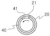
3 is a front cross-sectional view showing a cross-section taken along line AA of FIG. 2;
4 to 6 are reference views showing the operation of the cannula device for triple removal of haemorrhage according to the present invention.
이하, 본 발명을 첨부된 예시도면에 의거하여 상세히 설명한다.Hereinafter, the present invention will be described in detail based on the accompanying illustrative drawings.
도 2 내지 도 6은 본 발명에 따른 액취증 삼중제거술 캐뉼라장치는 손잡이(10)와, 상기 손잡이(10)에서 전방으로 연장된 캐뉼라(20)를 포함하며, 상기 캐뉼라(20)는 전후방향으로 연장되며 전단부는 밀폐되고 후단부는 흡입관(31)을 통해 흡입장치(30)에 연결되며 전단부 둘레면에는 여러개의 흡입공(21)이 형성된 금속재의 관체형상으로 구성된 것은 종래와 동일하다.2 to 6 show a cannula device for triple removal of odor according to the present invention comprising a
이때, 상기 흡입공(21)은 상기 캐뉼라(20)의 상면에 상호 전후방향으로 이격되도록 3개가 일렬로 형성된다.At this time, three
그리고, 상기 캐뉼라(20)의 후단부는 하측으로 연장되도록 구성된다.And, the rear end of the
그리고, 본 발명에 따르면, 상기 캐뉼라(20)의 내부에 전후방향으로 슬라이드가능하게 결합되어 상기 흡입공(21)의 내측단을 밀폐하는 밀폐부재(40)와, 상기 손잡이(10)의 내부에 구비되며 상기 밀폐부재(40)를 전후방향으로 슬라이드시키는 슬라이드구동수단(50)과, 상기 밀폐부재(40)에 연결되어 밀폐부재(40)를 측방향으로 회전시키는 회전구동수단(60)이 더 구비된다.And, according to the present invention, a sealing
상기 밀폐부재(40)는 도 2 및 도 3에 도시한 바와 같이, 전후방향으로 연장되며 외경이 상기 캐뉼라(20)의 내경에 대응되도록 구성된 관체형상으로 구성된 것으로, 후단부에는 상기 캐뉼라(20)의 후방으로 연장된 회전축(42)이 구비되며, 상기 회전축(42)의 후단부가 상기 슬라이드구동수단(50)에 회전가능하게 결합된다.As shown in FIGS. 2 and 3, the sealing
이를 위해, 상기 회전축(42)의 후단부에는 회전식 커플러(43)가 구비된다.To this end, a
그리고, 상기 밀폐부재(40)에는 복수개의 연통공(41)이 전후방으로 이격되도록 형성되고, 상기 연통공(41)은 상기 밀폐부재(40)가 전후방향으로 슬라이드되면, 상기 흡입공(21)중 어느 하나에 선택적으로 연결되어 흡입공(21)중에서 어느 하나만 선택적으로 개방되도록 구성된다.In addition, a plurality of
이를 자세히 설명하면, 상기 연통공(41)은 상기 밀폐부재(40)의 상면에 3개가 상호 전후방향으로 이격되도록 형성되며, 각각의 연통공(41)은 상기 흡입공(21)의 간격에 비해 좁게 전후방향으로 이격되도록 형성된다.In detail, three
바람직하게는, 중앙부에 위치된 연통공(41)이 중앙부에 위치된 흡입공(21)에 연통된 상태에서, 전방에 위치된 연통공(41)은 전방에 위치된 흡입공(21)의 후방에 위치되고, 후방에 위치된 연통공(41)은 후방에 위치된 흡입공(21)의 전방에 위치되도록 간격이 조절된다.Preferably, in a state in which the
따라서, 도 2에 도시한 바와 같이, 상기 밀폐부재(40)가 중앙부에 위치되면, 중앙부에 위치된 연통공(41)과 흡입공(21)이 상호 연통되고, 도 4에 도시한 바와 같이, 밀폐부재(40)를 전방으로 슬라이드시키면 전방에 위치된 연통공(41)과 흡입공(21)이 상호 연통되며, 도 5에 도시한 바와 같이, 밀폐부재(40)를 후방으로 슬라이드시키면 후방에 위치된 연통공(41)과 흡입공(21)이 상호 연통된다.Therefore, as shown in FIG. 2, when the
상기 슬라이드구동수단(50)은 구동모터에 의해 작동되는 크랭크기구를 이용하는 것으로, 커넥팅로드가 상기 밀폐부재(40)의 회전축(42)에 구비된 회전식 커플러(43)의 후단부에 연결되어, 슬라이드구동수단(50)을 작동시키면, 상기 밀폐부재(40)가 정해진 속도로 전후방향으로 반복적으로 슬라이드된다.The slide driving means 50 uses a crank mechanism operated by a driving motor, and a connecting rod is connected to the rear end of the
상기 회전구동수단(60)은 웜기어(61)와 웜휠(62)에 의해 상기 회전축(42)에 연결된 서버모터(63)를 이용하는 것으로, 상기 손잡이(10)의 내부에 구비되어, 서버모터(63)를 구동시키면, 상기 회전축(42)과 밀폐부재(40)가 측방향으로 회전되어, 연통공(41)과 흡입공(21)이 연통되는 면적이 변화되어, 흡입공(21)이 개방되는 면적을 조절할 수 있다.The rotation driving means 60 uses a
즉, 상기 연통공(41)과 흡입공(21)이 정확히 일치되어 흡입공(21)이 전부 개방된 상태에서, 도 6에 도시한 바와 같이, 흡입공(21)을 측방향으로 회전시키면, 연통공(41)이 측방향으로 회전되면서 흡입공(21)이 개방되는 면적이 점차 줄어들게 되다.That is, when the
이때, 상기 웜휠(62)은 상기 회전축(42)의 외측에 길이방향으로 슬라이되되 측방향으로 회전되지 않도록 스프라인결합되어, 회전축(42)이 전후방향으로 슬라이드되더라도 상기 웜휠(62)은 슬라이드되지 않으면서, 상기 회전축(42)에 기계적으로 연결되도록 구성된다.At this time, the
그리고, 상기 손잡이(10)에는 상기 슬라이드구동수단(50)과 회전구동수단(60)의 작동을 제어하기 위한 스위치가 구비된다.In addition, the
이와 같이 구성된 액취증 삼중제거술 캐뉼라장치의 작용을 설명하면 다음과 같다.The operation of the cannula device configured in this way for triple removal of haemorrhage will be described as follows.
우선, 시술자가 상기 캐뉼라(20)가 피하의 진피층으로 삽입되도록 한 상태에서, 상기 흡입장치(30)를 구동시키고, 상기 스위치를 조작하여 슬라이드구동수단(50)을 구동시키면, 상기 밀폐부재(40)가 전후방향으로 슬라이드되면서, 상기 연통공(41)이 상기 캐뉼라(20)에 형성된 3개의 흡입공(21) 중에서 어느 하나에 순차적으로 연통되어, 3개의 흡입공(21)이 번갈아가면서 개방되도록 한다.First, when the operator drives the
따라서, 상기 흡입장치(30)에 의해 발생된 진공압에 의해 땀샘조직이 3개의 흡입공(21)을 통해 번갈아가면서 흡입된다.Accordingly, the sweat gland tissue is alternately sucked through the three
또한, 시술자가 상기 스위치를 조작하여 상기 회전구동수단(60)을 구동시키면, 상기 밀폐부재(40)가 측방향으로 회전되면서 상기 흡입공(21)이 개방되는 면적을 조절함으로써, 흡입공(21)을 통해 땀샘조직이 흡입되는 속도를 조절할 수 있다.In addition, when the operator operates the switch to drive the rotation driving means 60, the sealing
이와 같이 구성된 액취증 삼중제거술 캐뉼라장치는 슬라이드구동수단(50)으로 밀폐부재(40)를 전후방향으로 슬라이드시키면, 캐뉼라(20)에 형성된 3개의 흡입공(21)이 순차적으로 하나씩 개방됨으로, 흡입장치(30)에 의해 발생된 진공압이 각각의 흡입공(21)에 온전하게 전달되어, 각각의 흡입공(21)을 통해 균일하게 땀샘조직을 흡입할 수 있는 장점이 있다.The three
또한, 상기 회전구동수단(60)으로 밀폐부재(40)를 측방향으로 회전시켜, 흡입공(21)의 개폐정도를 조절할 수 있음으로, 피부의 하측에 남아있는 땀샘조직의 양이 줄어들었을 때, 흡입공(21)의 개방량을 줄어 땀샘조직이 천천히 흡입되도록 함으로써, 피부조직에 불필요하게 강한 진공압이 작용되어 피부조직이 손상되는 것을 방지할 수 있다.In addition, by rotating the sealing
10. 손잡이20. 캐뉼라
30. 흡입장치40. 밀폐부재
50. 슬라이드구동수단60. 회전구동수단10.
30.
50. Slide drive means 60. Rotation drive means
Claims (2)
Translated fromKorean상기 손잡이(10)에서 전방으로 연장된 캐뉼라(20)를 포함하며,
상기 캐뉼라(20)는 전후방향으로 연장되며 전단부는 밀폐되고 후단부는 흡입관(31)을 통해 흡입장치(30)에 연결되며 전단부 둘레면에는 여러개의 흡입공(21)이 형성된 금속재의 관체형상으로 구성된 액취증 삼중제거술 캐뉼라장치에 있어서,
상기 캐뉼라(20)의 내부에 전후방향으로 슬라이드가능하게 결합되어 상기 흡입공(21)의 내측단을 밀폐하는 밀폐부재(40)와,
상기 손잡이(10)의 내부에 구비되며 상기 밀폐부재(40)를 전후방향으로 슬라이드시키는 슬라이드구동수단(50)을 더 포함하며,
상기 밀폐부재(40)에는 복수개의 연통공(41)이 전후방으로 이격되도록 형성되고,
상기 연통공(41)은 상기 밀폐부재(40)가 전후방향으로 슬라이드되면, 상기 흡입공(21)중 어느 하나에 선택적으로 연결되어 흡입공(21)중에서 어느 하나만 선택적으로 개방되도록 구성되어,
상기 슬라이드구동수단(50)으로 밀폐부재(40)를 전후방향으로 슬라이드시키면, 상기 흡입공(21)중에서 어느 하나만 선택적으로 개방되되,
상기 밀폐부재(40)는 전후방향으로 연장되며 외경이 상기 캐뉼라(20)의 내경에 대응되도록 구성된 관체형상으로 구성되고, 후단부가 상기 슬라이드구동수단(50)에 측방향으로 회전가능하게 연결되며,
상기 밀폐부재(40)의 후단부에 연결되어 밀폐부재(40)를 회전시키는 회전구동수단(60)을 포함하는 것을 특징으로 하는 액취증 삼중제거술 캐뉼라장치.
a handle (10) and
and a cannula (20) extending forwardly from the handle (10);
The cannula 20 extends in the front-rear direction, the front end is sealed, the rear end is connected to the suction device 30 through the suction pipe 31, and a plurality of suction holes 21 are formed on the peripheral surface of the front end. In the configured bromhidrosis triple ablation cannula device,
A sealing member 40 that is slidably coupled to the inside of the cannula 20 in the front-rear direction to seal the inner end of the suction hole 21;
It is provided inside the handle (10) and further includes a slide driving means (50) for sliding the sealing member (40) in the front-rear direction,
A plurality of communication holes 41 are formed in the sealing member 40 to be spaced apart in front and rear,
The communication hole 41 is selectively connected to any one of the suction holes 21 when the sealing member 40 slides in the front and rear direction so that only one of the suction holes 21 is selectively opened,
When the sealing member 40 is slid in the front-rear direction by the slide driving means 50, any one of the suction holes 21 is selectively opened,
The sealing member 40 is extended in the front-rear direction and has an outer diameter configured to correspond to the inner diameter of the cannula 20, and the rear end is rotatably connected to the slide driving means 50 in the lateral direction,
A triple removal surgery cannula device for malodor, characterized in that it is connected to the rear end of the closure member (40) and comprises a rotation driving means (60) for rotating the closure member (40).
Priority Applications (1)
| Application Number | Priority Date | Filing Date | Title |
|---|---|---|---|
| KR1020210043130AKR102314668B1 (en) | 2021-04-02 | 2021-04-02 | cannula device for aspirating sweat glands |
Applications Claiming Priority (1)
| Application Number | Priority Date | Filing Date | Title |
|---|---|---|---|
| KR1020210043130AKR102314668B1 (en) | 2021-04-02 | 2021-04-02 | cannula device for aspirating sweat glands |
Publications (1)
| Publication Number | Publication Date |
|---|---|
| KR102314668B1true KR102314668B1 (en) | 2021-10-20 |
Family
ID=78267954
Family Applications (1)
| Application Number | Title | Priority Date | Filing Date |
|---|---|---|---|
| KR1020210043130AActiveKR102314668B1 (en) | 2021-04-02 | 2021-04-02 | cannula device for aspirating sweat glands |
Country Status (1)
| Country | Link |
|---|---|
| KR (1) | KR102314668B1 (en) |
Cited By (1)
| Publication number | Priority date | Publication date | Assignee | Title |
|---|---|---|---|---|
| KR102446321B1 (en)* | 2021-12-16 | 2022-09-22 | 정병태 | Osmidrosis triple removal cannula device for aspirating sweat glands |
Citations (5)
| Publication number | Priority date | Publication date | Assignee | Title |
|---|---|---|---|---|
| US4416291A (en)* | 1981-07-20 | 1983-11-22 | Becton Dickinson And Company | Multiple sample needle assembly with vein entry indicator |
| KR200367222Y1 (en) | 2004-08-25 | 2004-11-10 | 김래범 | Cannula for surgical operation of bromidrosis |
| KR20170100212A (en)* | 2016-02-25 | 2017-09-04 | 정병태 | Osmidrosis triple removal cannula device for aspirating sweat glands |
| KR101794273B1 (en)* | 2016-06-22 | 2017-11-07 | 배준 | Surgical instrument ist for treatment for osmidrosis axillae |
| JP2019022766A (en)* | 2013-03-12 | 2019-02-14 | マグノリア メディカル テクノロジーズ,インコーポレイテッド | Method and apparatus for selectively occluding a lumen of a needle |
- 2021
- 2021-04-02KRKR1020210043130Apatent/KR102314668B1/enactiveActive
Patent Citations (5)
| Publication number | Priority date | Publication date | Assignee | Title |
|---|---|---|---|---|
| US4416291A (en)* | 1981-07-20 | 1983-11-22 | Becton Dickinson And Company | Multiple sample needle assembly with vein entry indicator |
| KR200367222Y1 (en) | 2004-08-25 | 2004-11-10 | 김래범 | Cannula for surgical operation of bromidrosis |
| JP2019022766A (en)* | 2013-03-12 | 2019-02-14 | マグノリア メディカル テクノロジーズ,インコーポレイテッド | Method and apparatus for selectively occluding a lumen of a needle |
| KR20170100212A (en)* | 2016-02-25 | 2017-09-04 | 정병태 | Osmidrosis triple removal cannula device for aspirating sweat glands |
| KR101794273B1 (en)* | 2016-06-22 | 2017-11-07 | 배준 | Surgical instrument ist for treatment for osmidrosis axillae |
Cited By (1)
| Publication number | Priority date | Publication date | Assignee | Title |
|---|---|---|---|---|
| KR102446321B1 (en)* | 2021-12-16 | 2022-09-22 | 정병태 | Osmidrosis triple removal cannula device for aspirating sweat glands |
Similar Documents
| Publication | Publication Date | Title |
|---|---|---|
| US4909782A (en) | Tissue punch | |
| US20190192218A1 (en) | Surgical device and method of use | |
| US10617399B2 (en) | Self-contained handheld biopsy needle | |
| CA2804200C (en) | Devices and methods for cutting and evacuating tissue | |
| JP3466620B2 (en) | Device for removing obstruction in pipe | |
| WO2002069808A3 (en) | Biopsy apparatus | |
| KR102314668B1 (en) | cannula device for aspirating sweat glands | |
| JP2000312679A (en) | Method for controlling tissue sampling by using biopsy device | |
| US20160242844A1 (en) | Surgical fluid management system and method of use | |
| JP2000316867A (en) | Control device for tissue gathering using biopsy device | |
| JP2001511053A (en) | Medical syringe | |
| EP2884914A1 (en) | Devices and methods for cutting tissue | |
| CN211633382U (en) | Tissue rotary-cut device | |
| CN207755388U (en) | A kind of plantation mobile phone | |
| CN215129151U (en) | Mammary gland puncture and cutting device with blood coagulation function | |
| CN208511073U (en) | Accurate rotary-cut biopsy sampler | |
| CN117442302A (en) | Hair follicle extraction device, control method and extraction method | |
| CN215079456U (en) | Bone cleaning device | |
| CN109044493B (en) | Multifunctional tumor stripping scissors | |
| CN211610938U (en) | Flushing and sucking assembly | |
| CN109168330A (en) | A kind of labour saving shovel | |
| CN210228273U (en) | Scalpel for surgical operation | |
| CN222899822U (en) | Aspirator for plastic surgery | |
| CN220089571U (en) | Novel medical planing device handle | |
| CN219289611U (en) | Short needle point type needle head structure of rotary cutting needle and rotary cutting needle |
Legal Events
| Date | Code | Title | Description |
|---|---|---|---|
| PA0109 | Patent application | St.27 status event code:A-0-1-A10-A12-nap-PA0109 | |
| PA0201 | Request for examination | St.27 status event code:A-1-2-D10-D11-exm-PA0201 | |
| PA0302 | Request for accelerated examination | St.27 status event code:A-1-2-D10-D17-exm-PA0302 St.27 status event code:A-1-2-D10-D16-exm-PA0302 | |
| D13-X000 | Search requested | St.27 status event code:A-1-2-D10-D13-srh-X000 | |
| D14-X000 | Search report completed | St.27 status event code:A-1-2-D10-D14-srh-X000 | |
| PE0902 | Notice of grounds for rejection | St.27 status event code:A-1-2-D10-D21-exm-PE0902 | |
| E13-X000 | Pre-grant limitation requested | St.27 status event code:A-2-3-E10-E13-lim-X000 | |
| P11-X000 | Amendment of application requested | St.27 status event code:A-2-2-P10-P11-nap-X000 | |
| P13-X000 | Application amended | St.27 status event code:A-2-2-P10-P13-nap-X000 | |
| E701 | Decision to grant or registration of patent right | ||
| PE0701 | Decision of registration | St.27 status event code:A-1-2-D10-D22-exm-PE0701 | |
| GRNT | Written decision to grant | ||
| PR0701 | Registration of establishment | St.27 status event code:A-2-4-F10-F11-exm-PR0701 | |
| R18-X000 | Changes to party contact information recorded | St.27 status event code:A-5-5-R10-R18-oth-X000 | |
| PR1002 | Payment of registration fee | St.27 status event code:A-2-2-U10-U11-oth-PR1002 Fee payment year number:1 | |
| PG1601 | Publication of registration | St.27 status event code:A-4-4-Q10-Q13-nap-PG1601 | |
| P22-X000 | Classification modified | St.27 status event code:A-4-4-P10-P22-nap-X000 | |
| PR1001 | Payment of annual fee | St.27 status event code:A-4-4-U10-U11-oth-PR1001 Fee payment year number:4 | |
| PR1001 | Payment of annual fee | St.27 status event code:A-4-4-U10-U11-oth-PR1001 Fee payment year number:5 |