KR102306581B1 - Method and apparatus for measuring optical lenses for individual wearing situations by a user - Google Patents
Method and apparatus for measuring optical lenses for individual wearing situations by a userDownload PDFInfo
- Publication number
- KR102306581B1 KR102306581B1KR1020207030591AKR20207030591AKR102306581B1KR 102306581 B1KR102306581 B1KR 102306581B1KR 1020207030591 AKR1020207030591 AKR 1020207030591AKR 20207030591 AKR20207030591 AKR 20207030591AKR 102306581 B1KR102306581 B1KR 102306581B1
- Authority
- KR
- South Korea
- Prior art keywords
- lens
- dimensional shape
- image data
- optical effect
- measuring
- Prior art date
- Legal status (The legal status is an assumption and is not a legal conclusion. Google has not performed a legal analysis and makes no representation as to the accuracy of the status listed.)
- Active
Links
Images


Classifications
- G—PHYSICS
- G01—MEASURING; TESTING
- G01M—TESTING STATIC OR DYNAMIC BALANCE OF MACHINES OR STRUCTURES; TESTING OF STRUCTURES OR APPARATUS, NOT OTHERWISE PROVIDED FOR
- G01M11/00—Testing of optical apparatus; Testing structures by optical methods not otherwise provided for
- G01M11/02—Testing optical properties
- G01M11/0242—Testing optical properties by measuring geometrical properties or aberrations
- G01M11/0257—Testing optical properties by measuring geometrical properties or aberrations by analyzing the image formed by the object to be tested
- G01M11/0264—Testing optical properties by measuring geometrical properties or aberrations by analyzing the image formed by the object to be tested by using targets or reference patterns
- G—PHYSICS
- G01—MEASURING; TESTING
- G01B—MEASURING LENGTH, THICKNESS OR SIMILAR LINEAR DIMENSIONS; MEASURING ANGLES; MEASURING AREAS; MEASURING IRREGULARITIES OF SURFACES OR CONTOURS
- G01B11/00—Measuring arrangements characterised by the use of optical techniques
- G01B11/24—Measuring arrangements characterised by the use of optical techniques for measuring contours or curvatures
- G01B11/245—Measuring arrangements characterised by the use of optical techniques for measuring contours or curvatures using a plurality of fixed, simultaneously operating transducers
- A—HUMAN NECESSITIES
- A61—MEDICAL OR VETERINARY SCIENCE; HYGIENE
- A61B—DIAGNOSIS; SURGERY; IDENTIFICATION
- A61B3/00—Apparatus for testing the eyes; Instruments for examining the eyes
- A61B3/0016—Operational features thereof
- A61B3/0025—Operational features thereof characterised by electronic signal processing, e.g. eye models
- A—HUMAN NECESSITIES
- A61—MEDICAL OR VETERINARY SCIENCE; HYGIENE
- A61B—DIAGNOSIS; SURGERY; IDENTIFICATION
- A61B3/00—Apparatus for testing the eyes; Instruments for examining the eyes
- A61B3/02—Subjective types, i.e. testing apparatus requiring the active assistance of the patient
- A61B3/028—Subjective types, i.e. testing apparatus requiring the active assistance of the patient for testing visual acuity; for determination of refraction, e.g. phoropters
- A61B3/04—Trial frames; Sets of lenses for use therewith
- A—HUMAN NECESSITIES
- A61—MEDICAL OR VETERINARY SCIENCE; HYGIENE
- A61B—DIAGNOSIS; SURGERY; IDENTIFICATION
- A61B3/00—Apparatus for testing the eyes; Instruments for examining the eyes
- A61B3/10—Objective types, i.e. instruments for examining the eyes independent of the patients' perceptions or reactions
- A61B3/1005—Objective types, i.e. instruments for examining the eyes independent of the patients' perceptions or reactions for measuring distances inside the eye, e.g. thickness of the cornea
- A—HUMAN NECESSITIES
- A61—MEDICAL OR VETERINARY SCIENCE; HYGIENE
- A61B—DIAGNOSIS; SURGERY; IDENTIFICATION
- A61B3/00—Apparatus for testing the eyes; Instruments for examining the eyes
- A61B3/10—Objective types, i.e. instruments for examining the eyes independent of the patients' perceptions or reactions
- A61B3/103—Objective types, i.e. instruments for examining the eyes independent of the patients' perceptions or reactions for determining refraction, e.g. refractometers, skiascopes
- A61B3/1035—Objective types, i.e. instruments for examining the eyes independent of the patients' perceptions or reactions for determining refraction, e.g. refractometers, skiascopes for measuring astigmatism
- A—HUMAN NECESSITIES
- A61—MEDICAL OR VETERINARY SCIENCE; HYGIENE
- A61B—DIAGNOSIS; SURGERY; IDENTIFICATION
- A61B3/00—Apparatus for testing the eyes; Instruments for examining the eyes
- A61B3/10—Objective types, i.e. instruments for examining the eyes independent of the patients' perceptions or reactions
- A61B3/107—Objective types, i.e. instruments for examining the eyes independent of the patients' perceptions or reactions for determining the shape or measuring the curvature of the cornea
- G—PHYSICS
- G01—MEASURING; TESTING
- G01M—TESTING STATIC OR DYNAMIC BALANCE OF MACHINES OR STRUCTURES; TESTING OF STRUCTURES OR APPARATUS, NOT OTHERWISE PROVIDED FOR
- G01M11/00—Testing of optical apparatus; Testing structures by optical methods not otherwise provided for
- G01M11/02—Testing optical properties
- G—PHYSICS
- G02—OPTICS
- G02C—SPECTACLES; SUNGLASSES OR GOGGLES INSOFAR AS THEY HAVE THE SAME FEATURES AS SPECTACLES; CONTACT LENSES
- G02C7/00—Optical parts
- G02C7/02—Lenses; Lens systems ; Methods of designing lenses
- G02C7/024—Methods of designing ophthalmic lenses
- G—PHYSICS
- G01—MEASURING; TESTING
- G01M—TESTING STATIC OR DYNAMIC BALANCE OF MACHINES OR STRUCTURES; TESTING OF STRUCTURES OR APPARATUS, NOT OTHERWISE PROVIDED FOR
- G01M11/00—Testing of optical apparatus; Testing structures by optical methods not otherwise provided for
- G01M11/02—Testing optical properties
- G01M11/0207—Details of measuring devices
- G01M11/0214—Details of devices holding the object to be tested
Landscapes
- Health & Medical Sciences (AREA)
- Life Sciences & Earth Sciences (AREA)
- Physics & Mathematics (AREA)
- Ophthalmology & Optometry (AREA)
- Engineering & Computer Science (AREA)
- General Health & Medical Sciences (AREA)
- Molecular Biology (AREA)
- Public Health (AREA)
- Biomedical Technology (AREA)
- Heart & Thoracic Surgery (AREA)
- Medical Informatics (AREA)
- Veterinary Medicine (AREA)
- Surgery (AREA)
- Animal Behavior & Ethology (AREA)
- Biophysics (AREA)
- General Physics & Mathematics (AREA)
- Analytical Chemistry (AREA)
- Chemical & Material Sciences (AREA)
- Geometry (AREA)
- Signal Processing (AREA)
- Optics & Photonics (AREA)
- Eyeglasses (AREA)
- Length Measuring Devices By Optical Means (AREA)
- Testing Of Optical Devices Or Fibers (AREA)
Abstract
Translated fromKorean
Description
Translated fromKorean본 개시물은 안구 광학계(ophthalmic optics)의 분야에 관한 것이며, 특히, 측정 체적에 배치된 광학 렌즈, 특히 안경 렌즈의 광학 효과를 측정하기 위한 장치에 관한 것이다. 또한, 본 개시물은 측정 체적에 배치된 광학 렌즈, 특히 안경 렌즈의 공간 굴절률 분포를 측정하기 위한 장치에 관한 것이다. 또한, 본 개시물은 해당 장치를 보정하기 위한 방법, 측정 체적에 배치된 광학 렌즈의 광학 효과를 측정하기 위한 컴퓨터 구현 방법에 관한 것이다.The present disclosure relates to the field of ophthalmic optics, and in particular to a device for measuring the optical effect of an optical lens disposed in a measurement volume, in particular a spectacle lens. The present disclosure also relates to a device for measuring the spatial refractive index distribution of an optical lens, in particular a spectacle lens, disposed in a measurement volume. The present disclosure also relates to a method for calibrating a device in question, a computer implemented method for measuring the optical effect of an optical lens disposed in a measurement volume.
안경 렌즈의 경우, 일반적으로 관심사인 측정값은 정점 굴절력(vertex power: VP)이다. 정점 굴절력은 특정 관찰 상황에서의 렌즈의 유효 변수이다. 결과적으로, VP는 관찰자와의 거리 또는 렌즈 기울기에 따라 상이하다. 렌즈를 통과하는 광 빔을 직접 해석함으로써 VP를 확인하는 측정 기기는 항상 이러한 측정 기기 구성으로 VP를 결정할 것이다. 이러한 유효 변수는 성분의 모호하지 않은 조건(qualification)에 대해서만 제한적으로 사용된다. 따라서, 이를 해결하기 위해 ISO VP가 정의되었다. ISO VP는 평행한 입사광의 경우 표면 법선에 수직으로 측정된 VP이다. 이를 위해, 렌즈의 개별 위치에서 ISO VP를 결정하는 특정 측정 기기가 과거에 개발되었다.For spectacle lenses, a measurement of general interest is the vertex power (VP). The peak power is an effective parameter of a lens in a particular observation situation. Consequently, VP differs depending on the distance from the observer or the tilt of the lens. A measuring instrument that determines VP by directly interpreting the light beam passing through the lens will always determine VP with this measuring instrument configuration. These effective variables are of limited use only for the unambiguous qualification of ingredients. Therefore, ISO VP was defined to solve this. ISO VP is the VP measured perpendicular to the surface normal for parallel incident light. To this end, specific measuring instruments have been developed in the past to determine the ISO VP at individual positions of the lens.
ISO VP의 장점은 후자가 VP와 같은 유효 변수가 아니라, 고유한 성분 변수라는 점이다. 단점은 ISO VP가 착용 상황(착용 정점 굴절력 또는 착용 값이라고도 지칭됨)에서 안경의 효과으로부터 벗어날 수 있다는 점이다.The advantage of ISO VP is that the latter is a unique component variable, not an effective variable like VP. A disadvantage is that the ISO VP may deviate from the effect of the glasses in the wear situation (also referred to as wear peak power or wear value).
준비된 글레이즈드(glazed) 안경을 검사하기 위한 안경 설비를 갖는 렌즈 미터(lensmeter)가 DE 1 238 690 B1에서 알려져 있다. 이를 사용하여, 이미 안경테에 세팅된 안경 렌즈의 정점 굴절력을 결정하는 것이 가능하다.A lensmeter with a spectacle installation for examining prepared glazed spectacles is known from
EP 2 101 143 A1은 투명한 굴절 물체의 형상을 포착하기 위한 방법 및 장치를 개시한다. 투명한 굴절 물체의 형상을 포착하기 위한 방법에서, 측정될 물체가 삽입되어 이미징 시스템으로 투과된다. 이러한 방식으로 생성되는 변형된 이미징 시스템을 사용하여, 알려진 구조를 갖는 격자가 수납기 장치 상에 이미징되고, 생성되는 이미지가 평가된다. 알려진 구조를 갖는 평면형 격자가 사용되며, 이의 격자점은 격자 좌표계의 평가 가능한 공간 좌표에 할당된다. 이러한 평면형 격자 중 하나 이상은 측정될 물체에 대한 적어도 2개의 상이한 위치에서 삽입된다.
US 2016/0109362 A1은 국부적 굴절률을 결정하기 위한 방법 및 장치를 개시한다.US 2016/0109362 A1 discloses a method and apparatus for determining the local refractive index.
Knauer 등의 "투과의 편향 측정(deflectometry)을 통한 굴절력 측정"(DGaO 회의록, 2008년)은 굴절력을 결정하기 위한 편향 측정 방법을 기술한다.Knauer et al. "Power Measurement by Deflectometry of Transmission" (DGaO Minutes, 2008) describes a deflection measurement method for determining refractive power.
WO 2017/134275 A1은 렌즈의 광축 및/또는 물리적 특성을 결정하기 위한 방법 및 시스템, 그리고 머리 착용식 디스플레이 장치의 경우 및 가상 이미징 시에 이의 사용을 기술한다.WO 2017/134275 A1 describes a method and system for determining the optical axis and/or physical properties of a lens, and their use in the case of a head-mounted display device and in virtual imaging.
WO 2016/207412 A1은 측정 위치에 배치된 안경의 개별 데이터를 측정하기 위한 장치 및 방법을 개시하며, 상기 안경은 좌측 및/또는 우측 안경 렌즈를 갖는다. 장치는 테스트 구조물을 디스플레이하기 위한 디스플레이를 포함한다. 장치는, 안경의 좌측 안경 렌즈 및/또는 우측 안경 렌즈를 통과하는 이미징 빔 경로를 통해 테스트 구조물을 포착하기 위한 이미지 포착 장치를 포함한다. 장치는, 이미지 포착 장치에 의해 포착된 테스트 구조물의 이미지, 및 이미지 포착 장치에 대한 디스플레이의 알려진 공간 배향, 그리고 또한 이미지 포착 장치에 대한 안경의 알려진 공간 배향으로부터, 좌측 안경 렌즈 및/또는 우측 안경 렌즈의 적어도 하나의 구역에 대한 굴절력 분포를 결정하는 컴퓨터 프로그램을 갖는 컴퓨터 장치를 포함한다.
DE 10 2013 219 838 A1은 물체의 공간 구조를 확인하기 위한 방법 및 시스템을 개시한다.
DE 10 2014 005 281 A1은 공간에서 적어도 하나의 안경 렌즈의 위치를 결정하기 위한 방법 및 장치를 개시한다.
DE 10 2011 089 704 A1은 안경 렌즈, 안경 렌즈 블랭크, 또는 안경 렌즈 반제품에 관한 정보의 저장을 개시한다.WO 2016/207412 A1 discloses an apparatus and method for measuring individual data of glasses placed in a measuring position, said glasses having left and/or right spectacle lenses. The apparatus includes a display for displaying the test structure. The apparatus includes an image capture device for capturing a test structure through an imaging beam path passing through a left eyeglass lens and/or a right eyeglass lens of the eyeglasses. The device determines, from the image of the test structure captured by the image capture device and the known spatial orientation of the display relative to the image capture device, and also the known spatial orientation of the glasses with respect to the image capture device, the left spectacle lens and/or the right spectacle lens a computer device having a computer program for determining a refractive power distribution for at least one region of
DE 10 2013 219 838 A1 discloses a method and a system for ascertaining the spatial structure of an object.
DE 10 2014 005 281 A1 discloses a method and an apparatus for determining the position of at least one spectacle lens in space.
DE 10 2011 089 704 A1 discloses the storage of information regarding spectacle lenses, spectacle lens blanks or semi-finished spectacle lenses.
종래기술에서 알려진 기기는, 광학 요소의 효과가 하나의 측정 위치에서 초기에 결정되는 효과 측정 기기이다.Instruments known in the prior art are effect measuring instruments, in which the effect of an optical element is initially determined at one measuring position.
이러한 배경과 대비하여, 본 발명의 목적은, 광학 렌즈의 광학 효과의 더 유연한 결정을 가능하게 하는 측정 장치를 제공하는 것이다.
청구 대상은 독립 청구항에서 한정된다. 유리한 실시형태는 종속 청구항에 기술된다.Against this background, it is an object of the present invention to provide a measuring device which enables a more flexible determination of the optical effect of an optical lens.
The claimed subject matter is defined in the independent claims. Advantageous embodiments are described in the dependent claims.
따라서, 본 개시물의 제1 양태에 따라, 측정 체적에 배치된 광학 렌즈, 특히 안경 렌즈의 광학 효과를 측정하기 위한 장치를 제공하는 것이 제안되고, 장치는, 테스트 구조물을 디스플레이하도록 구성된 디스플레이 장치; 렌즈를 통과하는 이미징 빔 경로를 통해 복수의 시점(viewpoint)으로부터 테스트 구조물의 이미지 데이터를 포착하도록 구성된 이미지 포착 장치; 및 이미지 데이터에 기초하여 렌즈의 3차원 형상을 결정하고, 이의 3차원 형상에 기초하여 렌즈의 광학 효과를 산출하도록 구성된 컴퓨팅 장치를 포함하며, 렌즈는 안경 렌즈이다. 컴퓨팅 장치는, 이미지 데이터가 포착되는 측정 위치와 상이한 사용자의 지정된 착용 위치에 대해 안경 렌즈의 광학 효과를 산출하도록 구성된다.Accordingly, according to a first aspect of the present disclosure, it is proposed to provide an apparatus for measuring the optical effect of an optical lens, in particular a spectacle lens, disposed in a measurement volume, the apparatus comprising: a display device configured to display a test structure; an image capture device configured to capture image data of the test structure from a plurality of viewpoints via an imaging beam path passing through the lens; and a computing device configured to determine a three-dimensional shape of the lens based on the image data, and calculate an optical effect of the lens based on the three-dimensional shape thereof, wherein the lens is a spectacle lens. The computing device is configured to calculate the optical effect of the spectacle lens for a designated wearing position of the user that is different from the measurement position at which the image data is captured.
통상적인 렌즈 미터에 비해, 본 발명의 큰 장점은 특히, 개선된 비모호성(unambiguousness) 및/또는 적용 범위일 수 있다. 그 이유는 렌즈의 광학 효과가 통과하는 방사선의 방향에 따라 항상 좌우되기 때문이다. 광학 효과만을 측정하는 측정 기기는 측정 준비된 경우에만 후자를 신뢰 가능하게 결정할 수 있다. 이에 따라, 다수의 적용예에 대해 매우 명확한 표현(statement)이 이미 이루어질 수 있다.Compared to conventional lens meters, a great advantage of the present invention may in particular be improved unambiguousness and/or coverage. This is because the optical effect of a lens always depends on the direction of the radiation passing through it. A measuring instrument measuring only the optical effect can reliably determine the latter only if it is ready for measurement. Accordingly, a very clear statement can already be made for a number of applications.
그러나, 안경 렌즈의 측정 상황 및 실제 착용 상황 또는 착용 위치는, 신뢰 가능한 표현이 더 이상 가능하지 않을 정도로 서로 일치하지 않을 수 있거나 벗어날 수 있다. 따라서, 착용 위치에서의 광학 효과를 결정하기 위해, 착용 조건에서의 효과의 추가적인 측정이 필요하다.However, the measurement situation and the actual wearing situation or wearing position of the spectacle lens may not coincide with each other or may deviate to the extent that a reliable representation is no longer possible. Therefore, in order to determine the optical effect at the wearing position, additional measurements of the effect at the wearing condition are needed.
본 발명에 따른 솔루션은 상이한 접근법을 따른다: 렌즈의 3차원 형상이 초기에 결정된 후에만, 렌즈의 광학 효과가 산출되는 2단계 절차가 제안된다. 렌즈의 알려진 3차원 형상 또는 표면 형태(topography)는, 어떠한 보는 상황 또는 착용 상황에 대해서도 광학 효과가 후속적으로 산출될 수 있게 한다. 장점은 특히, 다양한 사용자별 요청에 대한 더 정확한 결과 및 더 개별화된 표현을 포함할 수 있다.The solution according to the invention follows a different approach: a two-step procedure is proposed in which the optical effect of the lens is calculated only after the three-dimensional shape of the lens has been initially determined. The known three-dimensional shape or topography of the lens allows the optical effect to be subsequently calculated for any viewing or wearing situation. Advantages may include, inter alia, more accurate results and more personalized representations for various user-specific requests.
디스플레이 장치는 테스트 구조물을 디스플레이한다. 테스트 구조물은 복수의 시점으로부터 이미지 포착 장치에 의해 포착된다. 테스트 구조물은 알려져 있기 때문에, 복수의 시점 각각에 대해, 이미지 포착 장치에 의해 포착된 테스트 구조물의 이미지 데이터 사이의 연관성이 형성될 수 있다. 이제 광학 렌즈가 디스플레이 장치와 이미지 포착 장치 사이의 측정 체적 내에 배치된 경우, 이미지 데이터의 각각의 픽셀과 테스트 구조물의 해당 이미지 요소 사이의 빔 경로가 영향을 받는다.The display device displays the test structure. The test structure is captured by an image capture device from a plurality of viewpoints. Since the test structure is known, for each of the plurality of viewpoints, an association can be formed between image data of the test structure captured by the image capture device. Now when an optical lens is placed within the measurement volume between the display device and the image capture device, the beam path between each pixel of image data and the corresponding image element of the test structure is affected.
그러나, 방법에서, WO 2016/207412 A1에 제시된 바와 같이, 단일 가상 굴절면만을 결정하는 것은 가능하지 않다. 이미징 빔 경로가 렌즈를 통과하면서, 제안된 솔루션에 따라 복수의 시점으로부터 이미지 데이터가 포착됨으로써, 특히, 테스트 구조물로부터 나오는 빔 경로가 광학 렌즈로 진입하는 전면 표면의 형상에 관하여 별도로 표현하는 것이 가능하며, 테스트 구조물로부터 나오는 빔 경로가 광학 렌즈로부터 나오는 후면 표면의 형상에 관하여 표현하는 것이 가능하다. 따라서, 다수의 방정식이 있는 방정식 체계가 이를 위해 설정될 수 있으며, 그 다음, 이에 기초하여, 빔 경로에 있는 표면이 재구성될 수 있다. 결과적으로, 전면 표면의 형상 및 후면 표면의 형상으로부터 렌즈의 3차원 형상이 형성된다.However, in the method, it is not possible to determine only a single virtual refractive surface, as presented in WO 2016/207412 A1. As the imaging beam path passes through the lens, image data is captured from multiple viewpoints according to the proposed solution, thereby making it possible to express separately in particular with respect to the shape of the front surface where the beam path exiting the test structure enters the optical lens, , it is possible to express in terms of the shape of the back surface that the beam path emanating from the test structure emerges from the optical lens. Thus, a system of equations with a number of equations can be established for this, and then, based on this, the surface in the beam path can be reconstructed. As a result, the three-dimensional shape of the lens is formed from the shape of the front surface and the shape of the rear surface.
그 후에, 알려진 방법을 사용하여, 3차원 형상에 기초하는 광학 효과의 산출이 구현될 수 있다.Thereafter, using known methods, the calculation of the optical effect based on the three-dimensional shape can be implemented.
전체 렌즈의 3차원 형상이 결정될 필요는 없음을 이해한다. 예를 들어, 일부분에 대해서만 산출이 구현될 수 있고, 예를 들어 측면 없이, 전면 및 후면 표면에 대해서만, 또는 사용자의 시야의 일부분에 대해서만 산출이 구현될 수 있다.It is understood that the three-dimensional shape of the entire lens need not be determined. For example, the calculation may be implemented for only a portion, eg, without the sides, only for the front and back surfaces, or for only a portion of the user's field of view.
컴퓨팅 장치에 의해 렌즈의 3차원 형상을 결정하는 경우, 예를 들어, 포착이 구현되는 각각의 시점에 대해 디스플레이 장치의 알려진 상대적 공간 위치와 같은, 보다 심층적인 정보가 유리하게 고려될 수 있다.When determining the three-dimensional shape of the lens by the computing device, more in-depth information can advantageously be taken into account, for example, the known relative spatial position of the display device for each viewpoint at which the capture is implemented.
추가적인 양태에 따라, 측정 체적에 배치된 광학 렌즈의 광학 효과를 측정하기 위한 장치가 제안되고, 장치는, 테스트 구조물을 디스플레이하도록 구성된 디스플레이 장치; 렌즈를 통과하는 이미징 빔 경로를 통해 복수의 시점으로부터 테스트 구조물의 이미지 데이터를 포착하도록 구성된 이미지 포착 장치; 및 이미지 데이터에 기초하여 렌즈의 3차원 형상을 결정하고, 이의 3차원 형상에 기초하여 렌즈의 광학 효과를 산출하도록 구성된 컴퓨팅 장치를 포함한다. 컴퓨팅 장치는, 렌즈의 하나 이상의 알려진 접촉점을 추가로 고려하여 렌즈의 3차원 형상을 결정하도록 구성될 수 있으며, 접촉점의 위치는, 안경 렌즈의 형상을 결정하는 알고리즘에 측정 체적에서의 후자의 위치에 대한 예상 값을 할당하기 위해 사용된다.
본 개시물의 추가적인 양태에 따라, 측정 체적에 배치된 광학 렌즈의 광학 효과를 측정하기 위한 장치가 제안되고, 장치는, 테스트 구조물을 디스플레이하도록 구성된 디스플레이 장치; 렌즈를 통과하는 이미징 빔 경로를 통해 복수의 시점으로부터 테스트 구조물의 이미지 데이터를 포착하도록 구성된 이미지 포착 장치; 및 이미지 데이터에 기초하여 렌즈의 3차원 형상을 결정하고, 이의 3차원 형상에 기초하여 렌즈의 광학 효과를 산출하도록 구성된 컴퓨팅 장치를 포함한다. 컴퓨팅 장치는 경계 조건을 고려하여 렌즈의 3차원 형상을 결정하도록 구성될 수 있으며, 경계 조건은 측정될 렌즈에 관한 정보를 판독함으로써 결정되고, 경계 조건은 렌즈 상의 코드를 판독함으로써 결정된다.
본 발명의 이해를 도울 수 있는 본 개시물의 추가적인 예시적인 양태에 따라, 측정 체적에 배치된 광학 렌즈의 개별 데이터를 측정하기 위한 장치를 보정하기 위한 방법이 제공되고, 방법은, 테스트 구조물을 제공하거나 디스플레이 장치를 통해 테스트 구조물을 디스플레이하는 단계; 이미지 포착 장치와 디스플레이 장치 사이의 제1 거리를 설정하고, 제1 거리로부터 이미지 포착 장치를 통해 테스트 구조물의 이미지 데이터를 포착하는 단계; 이미지 포착 장치와 디스플레이 장치 사이의 제2 거리를 설정하고, 제2 거리로부터 이미지 포착 장치를 통해 테스트 구조물의 이미지 데이터를 포착하는 단계; 제1 거리에서 포착된 이미지 데이터, 및 제2 거리에서 포착된 이미지 데이터에 기초하여, 이미지 포착 장치에 의해 포착된 입사광 빔의 방향, 및 이미지 데이터의 해당 픽셀을 결정하는 단계를 포함한다.According to a further aspect, an apparatus for measuring the optical effect of an optical lens disposed in a measurement volume is proposed, the apparatus comprising: a display device configured to display a test structure; an image capture device configured to capture image data of the test structure from a plurality of viewpoints via an imaging beam path passing through the lens; and a computing device configured to determine a three-dimensional shape of the lens based on the image data, and calculate an optical effect of the lens based on the three-dimensional shape thereof. The computing device may be configured to determine the three-dimensional shape of the lens further taking into account one or more known contact points of the lens, the location of the contact point being determined by an algorithm for determining the shape of the spectacle lens at the latter location in the measurement volume. used to assign expected values to
According to a further aspect of the present disclosure, an apparatus for measuring an optical effect of an optical lens disposed in a measurement volume is proposed, the apparatus comprising: a display device configured to display a test structure; an image capture device configured to capture image data of the test structure from a plurality of viewpoints via an imaging beam path passing through the lens; and a computing device configured to determine a three-dimensional shape of the lens based on the image data, and calculate an optical effect of the lens based on the three-dimensional shape thereof. The computing device may be configured to determine a three-dimensional shape of the lens in consideration of a boundary condition, the boundary condition being determined by reading information about the lens to be measured, and the boundary condition being determined by reading a code on the lens.
According to a further exemplary aspect of the present disclosure that may aid in understanding the present invention, a method is provided for calibrating an apparatus for measuring individual data of an optical lens disposed in a measurement volume, the method comprising: providing a test structure or displaying the test structure through a display device; establishing a first distance between the image capturing device and the display device, and capturing image data of the test structure from the first distance through the image capturing device; establishing a second distance between the image capturing device and the display device, and capturing image data of the test structure from the second distance through the image capturing device; determining, based on the image data captured at the first distance, and the image data captured at the second distance, a direction of an incident light beam captured by the image capturing device and a corresponding pixel of the image data.
삭제delete
삭제delete
삭제delete
삭제delete
이러한 솔루션의 장점은 입사광 빔의 방향이 간단한 방식으로 결정될 수 있다는 점을 포함한다. 여기서, 어떤 경우에도 측정을 위해 사용되는 디스플레이 장치는 보정 목적으로도 역할을 할 수 있다. 바람직하게는, 이미지 포착 장치에 대한 이의 영상점(image point)을 포함하는 디스플레이 장치의 상대 위치가 보정 동안 고려될 수 있다.Advantages of this solution include that the direction of the incident light beam can be determined in a simple manner. Here, in any case, the display device used for measurement may also serve as a calibration purpose. Preferably, the relative position of the display device, including its image point with respect to the image capture device, can be taken into account during calibration.
높이 조정의 결과로서, 이미지 포착 장치에 대한, 예를 들어 이미지 포착 장치의 카메라에 대한, 입사광 빔의 각도가 변경된다. 알려진 높이 변화와 이를 수반하는 이미지 데이터의 테스트 구조물의 이미지 표현물의 변화 사이의 관계로부터 입사광의 방향이 결정될 수 있다. 이는 입사광 빔의 소위 "역전파(back propagation)"를 가능하게 한다.As a result of the height adjustment, the angle of the incident light beam with respect to the image capturing device, for example with respect to the camera of the image capturing device, is changed. The direction of the incident light can be determined from the relationship between the known height change and the accompanying change in the image representation of the test structure in the image data. This enables a so-called “back propagation” of the incident light beam.
본 개시물의 추가적인 양태에 따라, 측정 체적에 배치된 광학 렌즈, 특히 안경 렌즈의 광학 효과를 측정하기 위한 방법, 특히 컴퓨터 구현 방법이 개시되고, 방법은, 디스플레이 장치를 통해 디스플레이하기 위한 테스트 구조물을 제공하는 단계; 렌즈를 통과하는 이미징 빔 경로를 통해 복수의 시점으로부터 테스트 구조물의 이미지 데이터를 포착하는 단계; 이미지 데이터에 기초하여 렌즈의 3차원 형상을 결정하는 단계; 및 이의 3차원 형상에 기초하여 렌즈의 광학 효과를 산출하는 단계를 포함한다.According to a further aspect of the present disclosure, a method, in particular a computer implemented method, is disclosed for measuring the optical effect of an optical lens, in particular a spectacle lens, disposed in a measurement volume, the method comprising: providing a test structure for display via a display device to do; acquiring image data of the test structure from a plurality of viewpoints via an imaging beam path passing through the lens; determining a three-dimensional shape of the lens based on the image data; and calculating an optical effect of the lens based on its three-dimensional shape.
본 개시물의 추가적인 양태에 따라, 전술한 양태에 대응하는 방법이 제안된다.According to a further aspect of the present disclosure, a method corresponding to the above aspect is proposed.
본 개시물의 추가적인 양태에 따라, 컴퓨터에 의한 프로그램의 실행 시에, 후자로 하여금 전술한 방법 중 하나를 수행하도록 하는 명령을 포함하는 컴퓨터 프로그램 제품이 제안된다. 이 경우 방법 단계는 컴퓨터에 의해 수행되도록 설계됨을 이해한다. 예를 들어, 이미지 데이터를 포착하는 것은 이미지 데이터를 수신하는 것을 의미하는 것으로 이해될 수 있다. 따라서, 그 용어는 물리적 이미지 센서에 의해 생성된 측정 데이터의 전송으로 이해될 수 있다. 따라서, 테스트 구조물 데이터의 제공에 의해, 테스트 구조물이 제공될 수 있다. 결과적으로, 데이터는 디스플레이 장치에 의해 디스플레이될 수 있다.According to a further aspect of the present disclosure, a computer program product is proposed, comprising instructions, upon execution of the program by a computer, for causing the latter to perform one of the aforementioned methods. It is understood that the method steps in this case are designed to be performed by a computer. For example, capturing image data may be understood to mean receiving image data. Accordingly, the term may be understood as the transmission of measurement data generated by a physical image sensor. Thus, by providing test structure data, a test structure may be provided. As a result, the data can be displayed by the display device.
또한, 테스트 구조물의 제공은 컴퓨터 프로그램 제품에 의해 수행되지 않는 선행 단계일 수도 있다.Also, the provision of the test construct may be a preceding step not performed by the computer program product.
별도로 명시되지 않는 경우, 본원에 사용된 용어는 Deutsches Institut fuer Normung e.V.[독일 표준화 협회]의 표준 DIN EN ISO 13666:2012의 의미 내에서 이해되어야 한다.Unless otherwise specified, the terms used herein are to be understood within the meaning of the standard DIN EN ISO 13666:2012 of the Deutsches Institut fuer Normung e.V. [German Society for Standardization].
DIN EN ISO 13666:2012 표준의 5.8절에 따라, 전면 표면 또는 물체측 표면이라는 용어는 안경에서 눈으로부터 멀어지게 향하도록 의도된 안경 렌즈의 표면을 의미한다. DIN EN ISO 13666:2012 표준의 5.19절에 따라, 후면 표면 또는 안구측 표면이라는 용어는 눈으로 향하여 맞춰지도록 의도된 안경 렌즈의 표면을 의미한다. 이에 대한 대안으로서, 본 개시물의 범위 내에서 전면 표면이라는 용어는 디스플레이 장치를 향하는 렌즈의 표면을 의미할 수 있다. 따라서, 본 개시물의 범위 내에서 후면 표면은 디스플레이 장치로부터 멀어지게 향하는 표면을 지칭할 수 있다.According to clause 5.8 of the DIN EN ISO 13666:2012 standard, the term anterior surface or object-side surface means the surface of the spectacle lens intended to be directed away from the eye in the spectacles. According to clause 5.19 of the DIN EN ISO 13666:2012 standard, the term posterior surface or ocular surface means the surface of a spectacle lens intended to be fitted towards the eye. As an alternative to this, within the scope of the present disclosure the term front surface may mean the surface of the lens facing the display device. Accordingly, within the scope of the present disclosure a back surface may refer to a surface facing away from the display device.
일 구성예에서, 이미지 포착 장치는 제1 카메라 및 제2 카메라를 포함하도록 제공될 수 있으며, 제1 카메라는 제1 시점으로부터 제1 이미지 데이터를 포착하도록 구성되고, 제2 카메라는 제2 시점으로부터 제2 이미지 데이터를 포착하도록 구성되며, 컴퓨팅 장치는 제1 및 제2 이미지 데이터에 기초하여, 렌즈의 3차원 형상을 결정하도록 구성된다. 2개의 카메라의 사용에 대한 대안으로서, 상이한 위치에서 하나의 카메라를 사용하여, 제1 및 제2 이미지 데이터가 포착될 수도 있다. 제1 위치와 제2 위치 사이에서 카메라를 이동시키기 위한 변위 장치 또는 위치 추적 장치가 제공될 수 있다.In one configuration, an image capturing apparatus may be provided to include a first camera and a second camera, wherein the first camera is configured to capture first image data from the first viewpoint, and the second camera is configured to capture the first image data from the second viewpoint. and acquire the second image data, and the computing device is configured to determine a three-dimensional shape of the lens based on the first and second image data. As an alternative to the use of two cameras, the first and second image data may be captured using one camera at a different location. A displacement device or position tracking device may be provided for moving the camera between the first and second positions.
선택적인 전개예에서, 테스트 구조물이 제1 카메라에 의해 제1 각도로 포착될 수 있고 제2 카메라에 의해 제2 각도로 포착될 수 있도록, 제1 카메라 및 제2 카메라가 서로에 대해 비스듬히 배치될 수 있다.In an optional development, the first camera and the second camera may be positioned at an angle to each other such that the test structure can be captured by the first camera at a first angle and by the second camera at a second angle. can
렌즈는 안경 렌즈이며, 안경 렌즈의 광학 효과는 사용자의 주어진 착용 위치에 대해 산출된다. 한 가지 장점은 특히, 사용자의 임의의 주어진 지정된 또는 원하는 착용 위치에 대해, 광학 효과가 소급적으로 산출될 수도 있다는 점을 포함할 수 있다. 여기서, 착용 위치는 또한 이미지 데이터가 포착되는 측정 위치와는 크게 상이할 수 있다. 컴퓨팅 장치는, 이미지 데이터가 포착되는 측정 위치와 상이한 사용자의 지정된 착용 위치에 대해 안경 렌즈의 광학 효과를 산출하도록 구성될 수 있다. 특히, 사용되는 값의 유연한 산출 및 사용자별 조정이 있을 수 있다. 대조적으로, 통상적인 렌즈 미터는 사용자에 대한 개별화된 표현을 제공하지 않는다.The lens is a spectacle lens, and the optical effect of the spectacle lens is calculated for a given wearing position of the user. One advantage may include that the optical effect may be retrospectively calculated, particularly for any given designated or desired wearing position of the user. Here, the wearing position may also be significantly different from the measurement position at which the image data is captured. The computing device may be configured to calculate the optical effect of the spectacle lens for a designated wearing position of the user that is different from the measurement position at which the image data is captured. In particular, there may be flexible calculations of the values used and user-specific adjustments. In contrast, conventional lens meters do not provide a personalized representation of the user.
일 구성예에서, 컴퓨팅 장치는 집적 방법을 사용하여 렌즈의 3차원 형상을 반복적으로 결정하도록 구성되게 제공될 수 있다.In one configuration, the computing device may be provided configured to iteratively determine the three-dimensional shape of the lens using an integration method.
추가적인 구성예에서, 컴퓨팅 장치는 이미지 포착 장치에 진입하는 광 빔을 역추적하는 것에 기초하여, 렌즈의 3차원 형상을 결정하도록 구성되게 제공될 수 있다. 특히, 이미지 포착 장치에 진입하는 광 빔은 디스플레이 장치를 통해 디스플레이되는 테스트 구조물의 알려진 원래 위치로 역추적될 수 있다. 특히, 디스플레이 장치의 상대 위치, 및 이미지 데이터가 포착되는 위치 또는 시점은 알려져 있다. 선택적으로, 상대 위치는 거리 또는 높이의 변화를 통한 전술한 카메라 보정에 기초하여 확인될 수 있다. 예를 들어, 역전파 또는 역 광선 추적과 같은 방법을 사용하여, 렌즈의 3차원 형상을 결정할 수 있다. 간단히 말해서, 측정될 렌즈의 표면 재구성은, 포착된 이미지의 테스트 구조물의 하나 이상의 요소의 의도된 위치와 실제 위치의 비교에 기초하여 구현될 수 있다.In a further configuration, the computing device may be provided configured to determine a three-dimensional shape of the lens based on backtracing a light beam entering the image capture device. In particular, a light beam entering the image capture device may be traced back to a known original location of the test structure displayed via the display device. In particular, the relative position of the display device and the position or time point at which the image data is captured are known. Optionally, the relative position may be ascertained based on the camera calibration described above through a change in distance or height. For example, methods such as backpropagation or reverse ray tracing can be used to determine the three-dimensional shape of the lens. Briefly, the surface reconstruction of the lens to be measured may be implemented based on a comparison of the intended and actual positions of one or more elements of the test structure in the captured image.
일 구성예에서, 렌즈의 3차원 형상을 결정하는 것은, 표면 요소로의 렌즈의 전면 및/또는 후면 표면의 분할, 및 표면 요소의 정렬의 결정, 특히 표면 요소의 표면 법선의 결정을 포함할 수 있다. 특히, 이러한 결정은 이미지 포착 장치로 진입하는 광 빔을 역추적하는 것에 기초하여 수행될 수 있다. 달리 표현하면, 표면의 정렬은 개별 표면 요소에 대해(각각의 개별 표면 요소에 대해) 결정될 수 있다. 예를 들어, 표면 법선은 개별 구역 또는 표면 요소에 대해 산출될 수 있다.In one configuration, determining the three-dimensional shape of the lens may comprise dividing the front and/or rear surfaces of the lens into surface elements, and determining the alignment of the surface elements, in particular determining the surface normals of the surface elements. have. In particular, this determination may be performed based on tracing back a beam of light entering the image capture device. In other words, the alignment of the surface may be determined for an individual surface element (for each individual surface element). For example, surface normals can be calculated for individual regions or surface elements.
일 전개예에서, 컴퓨팅 장치는 표면 요소의 정렬에 기초하여, 렌즈의 전면 표면 및/또는 후면 표면의 3차원 형상을 결정하도록 구현될 수 있다. 렌즈의 표면, 예를 들어 전면 또는 후면 표면은 개별 표면 요소로 구성될 수 있다. 바람직하게는, 표면은 인접한 요소들 사이에 (현저한) 급격한 변화가 발생하지 않는 방식으로 구성된다.In one development, the computing device may be implemented to determine a three-dimensional shape of the anterior surface and/or the posterior surface of the lens based on the alignment of the surface elements. The surface of the lens, for example the anterior or posterior surface, may consist of individual surface elements. Preferably, the surface is constructed in such a way that no (significant) abrupt changes occur between adjacent elements.
일 구성예에서, 컴퓨팅 장치는, 렌즈의 전면 표면 또는 후면 표면이 파라미터화 가능한(parameterizable) 영역, 특히 평면, 구면, 원환체(torus) 또는 이들의 구역인 경계 조건을 고려하여, 렌즈의 3차원 형상을 결정하도록 구성될 수 있다. 경계 조건을 지정함으로써 파라미터 공간이 감소되기 때문에, 더 신속한 산출 및/또는 더 높은 정확도의 장점이 있다.In one configuration, the computing device configures the three-dimensionality of the lens, taking into account boundary conditions in which the anterior or posterior surface of the lens is a parameterizable region, in particular a plane, spherical, torus, or region thereof. may be configured to determine a shape. Since the parameter space is reduced by specifying boundary conditions, there are advantages of faster calculation and/or higher accuracy.
일 구성예에서, 컴퓨팅 장치는 렌즈의 하나 이상의 알려진 접촉점(들)을 추가로 고려하여, 렌즈의 3차원 형상을 결정하도록 구성되게 제공될 수 있다. 대안으로서 또는 이와 더불어, 컴퓨팅 장치는 경계 조건을 고려하여 렌즈의 3차원 형상을 결정하도록 구성되게 제공될 수 있으며, 경계 조건은 측정될 렌즈에 관한 정보를 판독함으로써, 특히 렌즈 상의 마킹 또는 코드를 판독함으로써 결정된다. 다시 한번, 자유도가 더 감소되기 때문에, 더 신속한 및/또는 더 정확한 산출의 장점이 있을 수 있다. 복수의 알려진 접촉점 또는 렌즈 유리 홀더 또는 안경 홀더가 고려될 수도 있음을 이해한다. 예를 들어, 곡률, 재료, 또는 굴절률에 관한 마커, 인그레이빙(engraving)은 렌즈 상의 코드로서 판독될 수 있으며, 산출 시에 고려될 수 있다.In one configuration, the computing device may be provided configured to further consider one or more known contact point(s) of the lens to determine the three-dimensional shape of the lens. Alternatively or in addition, the computing device may be provided configured to determine the three-dimensional shape of the lens taking into account a boundary condition, the boundary condition by reading information about the lens to be measured, in particular reading a marking or code on the lens. is determined by Once again, since the degrees of freedom are further reduced, there may be advantages of faster and/or more accurate calculations. It is understood that a plurality of known contact points or lens glass holders or spectacle holders may be contemplated. For example, markers relating to curvature, material, or index of refraction, engraving, can be read as codes on the lens and taken into account in calculations.
본 발명의 이해를 도울 수 있는 예시적인 구성예에서, 컴퓨팅 장치는 측정될 렌즈의 굴절률을 결정하도록, 특히 공간 굴절률 분포를 결정하도록 추가로 구성되게 제공될 수 있다. 하나의 굴절률을 갖는 렌즈 또는 안경 렌즈는 특수한 경우인 것으로 간주될 수 있다. 바람직하게는, 굴절률은 적어도 하나의 부분에서 일정하다. 또한, 소위 GRIN(그레이디드-인덱스) 렌즈의 공간 굴절률 분포가 결정될 수 있다. 본 발명자들은, 제안된 솔루션이 형상을 포착하는 역할을 할 수 있을 뿐만 아니라, 굴절률을 결정하는 역할, 즉 투명체의 내부를 측정하는 역할도 할 수 있음을 인식하였다. 예를 들어, 상이한 굴절률을 갖는 영역들 사이의 내부 계면을 결정하는 것이 가능하다. 가능한 적용예는 예를 들어, 다중(multi-part) 렌즈, 상이한 굴절률을 갖는 재료의 렌즈, 색지움 렌즈, 광학계 또는 대물렌즈를 포함한다.In an exemplary configuration that may aid understanding of the present invention, it may be provided that the computing device is further configured to determine the refractive index of the lens to be measured, in particular to determine a spatial refractive index distribution. A lens or spectacle lens with one refractive index may be considered a special case. Preferably, the refractive index is constant in at least one part. Also, the spatial refractive index distribution of a so-called GRIN (graded-index) lens can be determined. The inventors recognized that the proposed solution could serve not only to capture the shape, but also to determine the refractive index, i.e., to measure the inside of the transparent body. For example, it is possible to determine the internal interface between regions with different refractive indices. Possible applications include, for example, multi-part lenses, lenses of materials with different refractive indices, achromatic lenses, optics or objective lenses.
일 구성예에서, 장치는, 이미지 포착 장치와 디스플레이 장치 사이의 거리를 가변시키도록 구성된 높이 조정 장치를 더 포함할 수 있다. 또한, 컴퓨팅 장치는, 이미지 포착 장치와 디스플레이 장치 사이의 상이한 거리로부터 포착된 이미지 데이터에 기초하여, 이미지 포착 장치에 의해 포착된 광 빔의 빔 방향을 결정하도록 구성될 수 있다. 결과적으로, 픽셀과 빔 방향 사이의 연관성이 간단한 방식으로 설정될 수 있다.In one configuration, the device may further comprise a height adjustment device configured to vary the distance between the image capture device and the display device. Further, the computing device may be configured to determine a beam direction of a light beam captured by the image capturing device based on image data captured from different distances between the image capturing device and the display device. Consequently, the association between the pixel and the beam direction can be established in a simple manner.
따라서, 본 발명의 제1 양태에 대해 상세히 전술한 장점은 본 발명의 추가적인 양태에 적용된다.Accordingly, the advantages described above in detail with respect to the first aspect of the invention apply to a further aspect of the invention.
전술한 특징 및 이하에서 또한 설명될 특징은 본 발명의 범위를 벗어나지 않으면서, 각각의 경우에 명시된 조합으로 사용될 수 있을 뿐만 아니라, 다른 조합으로도 또는 그 자체로도 사용될 수 있음은 물론이다.It goes without saying that the features described above and also described below can be used not only in the combinations specified in each case, but also in other combinations or by themselves, without departing from the scope of the present invention.
본 발명의 실시형태는 도면에 도시되며, 이하의 설명에서 더 상세히 설명된다.
도 1은 측정 체적에 배치된 광학 렌즈의 광학 효과를 측정하기 위한 장치의 개략도를 도시한다;
도 2는 렌즈를 통하여 기록된 테스트 구조물의 예시적인 도면을 도시한다;
도 3은 기울어진 안경 렌즈를 통하여 기록된 테스트 구조물의 예시적인 도면을 도시한다;
도 4는 투명 물체를 통하는 빔 경로의 도면을 도시한다;
도 5는 렌즈를 통하는 빔 경로의 도면을 도시한다;
도 6은 파라미터화 가능한 표면 요소로 구성된 렌즈를 도시한다;
도 7은 측정 체적에 배치된 광학 렌즈의 광학 효과를 측정하기 위한 장치의 개략도를 도시한다;
도 8은 측정 체적에 배치된 광학 렌즈의 광학 효과를 측정하기 위한 장치의 추가적인 실시형태를 도시한다;
도 9는 측정 체적에 배치된 광학 렌즈의 광학 효과를 측정하기 위한 방법의 일 구성예의 흐름도를 도시한다;
도 10은 그러한 방법의 일 구성예의 상세한 흐름도를 도시한다;
도 11은 보정 방법의 일 실시형태의 흐름도를 도시한다;
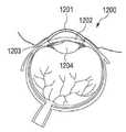
도 12는 눈의 개략도를 도시한다;
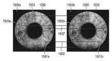
도 13은 홍채의 이미지 표현물과 함께 눈의 평면도의 이미지 표현물을 도시한다;
도 14는 각막을 측정하기 위한 장치의 개략도를 도시한다;
도 15는 상이한 시점으로부터 기록된 홍채의 이미지에서 이미지 특징부의 연관성 또는 상관관계를 도시한다;
도 16은 이미지 특징부의 추가적인 상관관계를 도시한다; 그리고
도 17은 각막을 측정하기 위한 방법의 일 실시형태의 흐름도를 도시한다.BRIEF DESCRIPTION OF THE DRAWINGS Embodiments of the invention are shown in the drawings and are explained in more detail in the description which follows.
1 shows a schematic diagram of a device for measuring the optical effect of an optical lens arranged in a measuring volume;
2 shows an exemplary view of a test structure recorded through a lens;
3 shows an exemplary view of a test structure recorded through an inclined spectacle lens;
4 shows a diagram of a beam path through a transparent object;
5 shows a diagram of the beam path through the lens;
6 shows a lens composed of a parameterizable surface element;
7 shows a schematic diagram of a device for measuring the optical effect of an optical lens arranged in a measuring volume;
8 shows a further embodiment of a device for measuring the optical effect of an optical lens arranged in a measuring volume;
9 shows a flow diagram of an example configuration of a method for measuring the optical effect of an optical lens disposed in a measurement volume;
10 shows a detailed flow diagram of one configuration of such a method;
11 shows a flowchart of one embodiment of a calibration method;
12 shows a schematic view of an eye;
13 shows an image representation of a top view of an eye with an image representation of the iris;
14 shows a schematic diagram of a device for measuring the cornea;
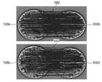
15 shows the association or correlation of image features in images of the iris recorded from different time points;
16 shows additional correlations of image features; and
17 shows a flow diagram of one embodiment of a method for measuring a cornea.
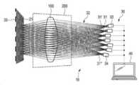
도 1에 도시된 장치(10)는 광학 렌즈(100), 특히 안경 렌즈의 광학 효과를 결정하는 역할을 한다. 장치(10)는 테스트 구조물(21)을 디스플레이하도록 구성된 디스플레이 장치(20)를 포함한다. 예를 들어, 이는 화면 또는 디스플레이일 수 있으며, 상이한 테스트 구조물을 디스플레이할 수 있다.The
장치(10)는, 렌즈(100)를 통과하는 이미징 빔 경로(32)를 통해 복수의 시점(31, 31', 31")으로부터 테스트 구조물(21)의 이미지 데이터를 포착하도록 구성된 이미지 포착 장치(30)를 더 포함한다. 다른 한편으로, 다양한 시점으로부터의 이미징 빔 경로는, 다양한 위치에 연속적으로 배치되는 하나의 카메라에 의해 연속적으로 기록될 수 있다. 그러나, 이미지 데이터를 병렬로 포착하기 위해, 복수의 카메라가 제공되는 것이 바람직하다. 혼합된 형태가 제공될 수도 있음을 이해한다. 예를 들어, 이미지 포착 장치(30)는 제1 카메라(33) 및 제2 카메라(34)를 포함할 수 있으며, 제1 카메라(33)는 제1 시점(33)으로부터 제1 이미지 데이터를 포착하도록 구성되고, 제2 카메라(34)는 제2 시점(33")으로부터 제2 이미지 데이터를 포착하도록 구성된다. 측정 체적(200)은 디스플레이 장치(20)를 통해 디스플레이 가능한 테스트 구조물(21)과 이미지 포착 장치(30) 사이에 위치된다.
장치(10)는 컴퓨팅 장치(40)를 더 포함한다. 예를 들어, 컴퓨팅 장치(40)는 컴퓨터, 마이크로컨트롤러, FPGA 등일 수 있다. 컴퓨팅 장치(40)는 이미지 데이터에 기초하여 렌즈(100)의 3차원 형상을 결정하고, 3차원 형상에 기초하여 렌즈(100)의 광학 효과를 산출하도록 구성된다. 달리 표현하면, 렌즈의 3차원 형상이 초기에 결정된 후에만, 이의 3차원 형상으로부터 렌즈의 광학 효과가 산출되는 2단계 절차가 제안된다.
본 개시물에 따른 이러한 접근법은 도 2 내지 도 6을 참조하여 아래에 더 상세히 설명될 것이다.This approach according to the present disclosure will be described in more detail below with reference to FIGS. 2-6 .
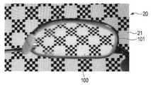
도 2는 렌즈(100)를 통하여 기록된 디스플레이 장치(20)의 테스트 구조물(21)의 평면도를 도시한다. 예를 들어, 이는 렌즈(100)를 통하여 카메라(33)에 의해 기록된 도 1에 따른 테스트 구조물(21)일 수 있다. 테스트 구조물(21)은 렌즈(100)로 인해 왜곡된 방식으로 재현된다. 렌즈(100)의 광학 효과에 관한 판단은 빔의 이러한 편향으로부터 이미 도출될 수 있다. 그러나, 렌즈(100)의 효과에 대하여 전반적으로 표현하는 것만이 가능하다.2 shows a top view of the
도 3은 카메라에 의해 기록된 추가적인 예시적인 이미지를 도시한다. 그러나, 이 경우, 광학 렌즈(100)를 갖는 안경(101)이 큰 기울기로 측정 영역에 배치되므로, 광학 렌즈(100)로 인해 야기된 빔 편향은 제한된 정확도로만 착용 위치에서의 실제 광학 효과를 재현한다.3 shows a further exemplary image recorded by the camera. However, in this case, since the
도 4는 렌즈(100)와 같은 투명 물체를 통하는 빔 경로의 예시적인 도면을 도시한다. 빔 경로의 원점은 디스플레이 장치(21) 상의 한정된 점(22)이다. 한정된 점(22)으로부터 나오는 빔 경로는 표면(102)에서 렌즈(101)에 진입하고, 표면(103)에서 렌즈로부터 나온다. 결과적으로, 이들은 렌즈(100)를 통과한다. 광 빔은 진입 표면(102) 및 출구 표면(103) 모두에서 굴절된다. 디스플레이 장치(20) 및 이미지 포착 장치(30)에 대한 렌즈(100)의 상대적 공간 위치 또는 배향에 따라, 상이한 광학 효과가 발생할 수 있다.4 shows an exemplary view of a beam path through a transparent object, such as
본 발명자들은, 복수의 시점으로부터 테스트 구조물을 기록하고 결과적으로 다수의 이미징 빔 경로(도 1을 또한 참조)를 포착함으로써, 광학 효과의 이러한 불확실성 또는 모호성이 해결될 수 있으며, 이로부터 결과적으로, 개재된 렌즈의 광학 특성이 결정될 수 있음을 인식하였다. 달리 표현하면, 다수의 방정식이 있는 방정식 체계가 이미징 빔 경로에 대해 설정될 수 있으며, 이러한 방정식은, 복수의 시점, 및 디스플레이 장치(20) 상의 이의 알려진 원점으로부터, 렌즈(100)를 통과하여 이미지 포착 장치에 진입하는 이미징 빔들 사이의 연관성을 각각 설정한다. 이로부터, 결과적으로, 렌즈(100)의 3차원 형상을 결정하는 것이 가능하며, 또한 선택적으로, 렌즈 내의 이의 굴절률 또는 제동력(brake-force) 분포를 결정하는 것도 가능하다.By recording the test structure from multiple viewpoints and consequently capturing multiple imaging beam paths (see also FIG. 1 ), the present inventors have found that this uncertainty or ambiguity of the optical effect can be resolved and, consequently, the intervening It was recognized that the optical properties of the lens can be determined. In other words, a system of equations with a number of equations can be established for the imaging beam path, such equations, from a plurality of viewpoints, and their known origins on the
렌즈(100)를 통하는 빔 경로의 간략화된 실시예는 도 5에서 재현된다. 디스플레이 장치(20) 상의 영상점(22)이 카메라(34)에 의해 포착된다. 빔 경로(110)는 렌즈(100)의 전면(102) 상의 점(104)에서 렌즈에 진입하고, 렌즈의 후면 표면(103) 상의 점(106)에서 렌즈로부터 나온다. 따라서, 간단히 말해서, 단지 하나의 카메라만으로 측정하는 경우, 2개의 미지수(이들 점에서의 표면의 공간 배향을 포함하는, 진입점(104) 및 출구점(105))가 있는 방정식이 존재한다. 이미지 포착 장치(30)가 추가적인 카메라(33)에 의해 표시된 바와 같은, 추가적인 시점으로부터 테스트 구조물을 기록함으로써, 추가적인 빔 경로(111 및 112)를 포착하는 것이 가능하다. 빔 경로(111)의 경우, 출구점(104)이 카메라(34)의 빔 경로(110)와 일치한다. 빔 경로(112)의 경우, 진입점(105)이 카메라(34)의 빔 경로(110)와 일치한다. 결과적으로, 복수의 방정식을 설정하는 것이 가능하며, 이로부터 디스플레이 장치(20)와 이미지 포착 장치(30) 사이에 배치된 렌즈(100)의 특성을 결정하는 것이 가능하다.A simplified embodiment of the beam path through the
이를 위해, 도 6에 예시적인 방식으로 도시된 바와 같이, 컴퓨팅 장치는, 바람직하게는 파라미터화 가능한 표면 요소로 이루어진 복합 표면으로서, 렌즈(100)를 모델링하도록 구성될 수 있다. 전면 및 후면 표면(102, 103)의 표면 요소(106, 107)의 배향은 점(104 및 105)에서의 빔의 편향으로부터 결정될 수 있다. 선택적으로, 렌즈(100) 내에서 추가적인 분할이 수행될 수 있다. 예를 들어, 렌즈(100) 내에서 추가적인 계면이 결정될 수 있다. 선택적으로, 컴퓨팅 장치는 렌즈(100)의 굴절률을 결정하거나, 그렇지 않으면 렌즈의 공간 굴절률 분포를 결정하도록 추가로 구현될 수 있다.To this end, as shown in an exemplary manner in FIG. 6 , the computing device may be configured to model the
선택적으로, 장치는 측정 체적에 배치된 광학 렌즈의 공간 굴절률 분포를 측정하기 위한 장치로서 구현될 수 있다. 이를 위해, 바람직하게는, 렌즈의 3차원 형상을 기술하는 렌즈 형상 데이터를 수신하도록 구성된 인터페이스가 제공될 수 있다. 이 경우, 렌즈의 형상이 산출될 필요가 없다; 대신에, 이는 이미지 데이터 및 렌즈 형상 데이터에 기초하여, 렌즈의 공간 굴절률 분포를 산출하기 위한 입력 파라미터로서 역할을 할 수 있다.Optionally, the device may be embodied as a device for measuring the spatial refractive index distribution of an optical lens disposed in the measurement volume. To this end, an interface may preferably be provided configured to receive lens shape data describing the three-dimensional shape of the lens. In this case, the shape of the lens need not be calculated; Instead, it may serve as an input parameter for calculating the spatial refractive index distribution of the lens, based on the image data and the lens shape data.
도 5 및 도 6을 참조하면, 컴퓨팅 장치는 이미지 포착 장치에 진입하는 광 빔을 역추적하는 것에 기초하여, 렌즈의 3차원 형상을 결정하도록 구성될 수 있다. 광 빔(110, 111, 112)이 이미지 포착 장치의 카메라(33, 34)에 진입하는 방향은 알려져 있다. 이를 위해, 아래에 계속 설명되는 바와 같이, 이미지 포착 장치가 보정될 수 있다. 결과적으로, 각각의 카메라(33, 34)로부터 비롯되는 진입 빔이 역추적될 수 있다. 이미지 포착 장치 또는 각각의 카메라(알려진 위치를 가짐)와 테스트 구조물(알려진 위치를 가짐) 사이의 빔 경로에 렌즈(100)가 위치된다. 렌즈(100)의 모델로부터 비롯되는 이러한 모델은, (알려진) 테스트 구조물이 렌즈(100)의 모델에 의해 이미징되어 이미지 포착 장치에 의해 포착된 이미지 데이터가 생성되는 방식으로, 컴퓨팅 장치에 의해 연속적으로 파라미터화될 수 있다. 특히, 파라미터화를 위해, 여기서 표면 법선(129, 130)으로 나타낸, 렌즈 표면을 형성하는 표면 요소들의 정렬을 조정하여 표면 요소들 사이의 거리(131)를 가변시키는 것이 가능하며, 선택적으로, 렌즈 내의 굴절률(n) 또는 굴절률 분포를 가변시키는 것이 가능하다.5 and 6 , the computing device may be configured to determine a three-dimensional shape of the lens based on tracing back a light beam entering the image capture device. The direction in which the
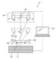
도 7 및 도 8은 측정 체적에 배치된 광학 렌즈(100)의 광학 효과를 측정하기 위한 장치(10)의 추가적인 실시형태를 도시한다. 해당 조립체는 동일한 참조 부호로 표시되며, 반복을 피하기 위해 다시 상세히 설명되지 않는다.7 and 8 show a further embodiment of a
도 8은 이미지 포착 장치(30)가 2개의 카메라(30, 31')를 포함하는 일 실시형태를 도시한다. 카메라는 상이한 시야각으로부터 패턴 또는 테스트 구조물(21)을 포착한다. 컴퓨팅 장치는 해당 이미지 데이터로부터 테스트 물체(4)를 재구성하도록 구현된다. 이를 위해, 도 5 및 도 6에서 설명된 바와 같이, 표면 요소로부터 또는 법선(129, 129')으로부터 기울기 필드(gradient field)를 결정하는 것이 가능하다.8 shows an embodiment in which the
테스트 구조물(21)의 한정된 원점에서 한정된 소스로부터의 광이 렌즈(100)를 통과하고, 보정된 카메라 시스템을 사용하여 상이한 시야각으로부터 이미지 포착 장치(30)에 의해 포착된다. 물체의 굴절 표면은 생성되는 이미지로부터 재구성된다.At a defined origin of the
그 원리는 하나의 카메라, 2개의 카메라, 또는 더 많은 카메라에서 작용한다. 유리한 실시형태에서 2개의 카메라가 사용되는데, 이 경우 합당한 비용/사용률이 달성될 수 있기 때문이다. 정확도를 추가로 증대시키기 위해, 심지어 더 많은 카메라가 사용될 수 있다.The principle works for one camera, two cameras, or more cameras. In an advantageous embodiment two cameras are used, since in this case a reasonable cost/utilization rate can be achieved. To further increase the accuracy, even more cameras can be used.
이미지 포착 장치(30) 또는 카메라(31, 31')는 기능이 알려진 방식으로 보정되며, 이를 통해 고유한 주 광선(카메라 광선)이 방향 및 원점으로부터 각각의 센서 좌표에 대해 3D로 도출될 수 있다. 이러한 보정은 종래기술에 따라 수행될 수 있다. 대안적으로, 카메라 및/또는 사용되는 대물렌즈의 알려진 광학 설계가 전술한 카메라 보정 대신에 카메라의 모델에 포함될 수 있다.The
예를 들어, 디스플레이 장치(20)는, 어레이로 배치된 발광 다이오드, TFT 또는 LED 디스플레이, 3D 디스플레이, 레이저 소스, 편광 디스플레이, 또는 그렇지 않으면 시준된, 선택적으로 구조화된 조명 장치와 같은, 자체 발광원을 가질 수 있다. 디스플레이 장치를 통해서도 발광될 수 있다. 예를 들어, 발광되는 디스플레이 장치는, 테스트 차트(예를 들어, 점 패턴 또는 체크무늬 패턴), 특히 규칙적인 3D 패턴, 알려지지 않은 많은 특징부가 있는(feature-rich) 평면형 이미지(작업 동안 위치가 추정될 수 있음), 또는 그렇지 않으면, 알려지지 않은 많은 특징부가 있는 3D 장면(최적화 동안 위치가 추정됨)을 가질 수 있다.For example, the
컴퓨팅 장치(40)는 3차원 형상을 결정하기 위한 추가적인 정보를 사용할 수 있다. 특히, 3차원 형상의 재구성은, 이미지 데이터를 포착하는 카메라의 알려진 시점 또는 위치, 그리고 테스트 구조물의 알려진 위치를 기반으로 할 수도 있다. 본 실시예에서, 이미지 데이터는 카메라 검출기 상에서 카메라에 진입하는 광 빔의 이미징의 위치일 수 있다. 이미지 포착 장치에 진입하는 광 빔은 이미지 데이터 및 알려진 시점으로부터 산출될 수 있다. 이미지 포착 장치의 보정은 이를 위한 기초로서 역할을 할 수 있다.The
선택적으로, 컴퓨팅 장치(40)는 하나 이상의 경계 조건을 고려하여, 렌즈의 3차원 형상을 결정하도록 추가로 구성될 수 있다. 예를 들어, 접촉점 또는 멈춤부(stop)(51)가 미리 결정될 수 있다. 렌즈(100)의 상대 위치는 이러한 점에서 알려져 있으며, 렌즈의 3차원 형상을 결정할 때 고려될 수 있다. 또한, 렌즈의 전면 및/또는 후면 표면의 형상, 굴절률, 또는 재료 등과 같은 정보가 미리 결정될 수 있다. 선택적으로, 장치는, 예를 들어 인그레이빙 또는 마커(140)의 형태로 렌즈 상에 존재하는 정보를 판독하고, 3차원 형상을 결정하는 경우 및/또는 광학 효과를 산출하는 경우 이러한 정보를 고려하도록 구현될 수 있다.Optionally, the
본 발명의 특히 유리한 적용예는 안경 렌즈의 측정이며, 특히 가변 초점 안경 렌즈로도 알려진 프로그레시브 안경 렌즈의 측정이다. 그러나, 구면, 비구면, 원환체 또는 프리즘 렌즈와 같은, 더 간단한 안경 렌즈가 제안된 장치를 사용하여 마찬가지로 측정될 수 있다.A particularly advantageous application of the invention is the measurement of spectacle lenses, in particular of progressive spectacle lenses, also known as variable focus spectacle lenses. However, simpler spectacle lenses, such as spherical, aspheric, toric or prismatic lenses, can likewise be measured using the proposed device.
선택적으로, 컴퓨팅 장치는, 유사한 데이터를 제공하기 위한 지정된 측정 기기 구성으로 ISO 정점 굴절력 또는 정점 굴절력을 산출하도록 구성될 수 있다. 안경 렌즈로부터 동공까지의 거리(정점 거리) 및 이의 상대 위치(예를 들어, 안면 형태 각도 또는 "착용" 범초점 각도)와 같은, 착용자별 데이터를 제공함으로써, 사용 정점 굴절력을 산출하는 것이 가능하다.Optionally, the computing device may be configured to calculate the ISO peak power or peak power with a designated measurement instrument configuration for providing similar data. By providing wearer-specific data, such as the distance from the spectacle lens to the pupil (apex distance) and its relative position (e.g., face shape angle or “wearing” panfocal angle), it is possible to calculate the used peak power .
선택적으로, 복수의 테스트 물체가 측정 공간에서 동시에 측정될 수 있다. 좌측 및 우측 안경 렌즈를 갖는 안경이 측정되는 경우, 컴퓨팅 장치는, 서로에 대한 안경 렌즈들의 위치 및 상대 위치를 결정하도록 추가로 구현될 수 있다. 이로부터, 예를 들어, 광 채널들의 거리와 같은, 추가적인 정보를 산출하는 것이 가능하다. 상이한 효과들의 구역들을 갖는 투명체가 복수의 테스트 물체로서 제공될 수도 있다. 예를 들어, 이는 복수의 구역을 갖는 렌즈(이중초점 렌즈, 삼중초점 렌즈, 또는 다초점 렌즈) 또는 2개의 렌즈를 갖는 안경일 수 있다.Optionally, a plurality of test objects may be simultaneously measured in the measurement space. When glasses with left and right spectacle lenses are measured, the computing device may be further implemented to determine the position and relative position of the spectacle lenses with respect to each other. From this it is possible to calculate additional information, for example the distance of the optical channels. A transparency having zones of different effects may be provided as a plurality of test objects. For example, it may be a lens with multiple zones (bifocal lens, trifocal lens, or multifocal lens) or spectacles with two lenses.
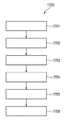
도 9는 아래에 설명되는 단계들을 포함하는, 측정 체적에 배치된 광학 렌즈, 특히 안경 렌즈의 광학 효과를 측정하기 위한 방법(900)의 흐름도를 도시한다. 제1 단계(901)에서, 디스플레이 장치를 통해 디스플레이하기 위한 테스트 구조물이 제공된다. 제2 단계(902)에서, 렌즈를 통과하는 이미징 빔 경로를 통해 복수의 시점으로부터 테스트 구조물의 이미지 데이터가 포착된다. 제3 단계(903)에서, 이미지 데이터(그리고 서로에 대한 디스플레이 장치 및 시점의 알려진 위치)에 기초하여, 렌즈의 3차원 형상이 결정된다. 제4 단계(904)에서, 이의 3차원 형상에 기초하여, 렌즈의 광학 효과가 산출된다. 임의의 사용 상황에 대해 산출이 구현될 수 있다. 결과적으로, 컴퓨팅 장치는 ISO 정점 굴절력에 해당하는 제1 광학 효과, 및 사용자의 사용 상황에 해당하는 제2 광학 효과를 산출하도록 구성될 수 있다.9 shows a flow diagram of a
선택적으로, 장치를 보정하는 단계(905)가 측정 방법에 선행될 수 있다.Optionally, a
장치를 보정하기 위한 해당 방법은 이하의 단계를 차례로 포함할 수 있다: 제1 보정 단계에서, 디스플레이 장치를 통해 테스트 구조물이 제공된다. 제2 보정 단계에서, 이미지 포착 장치와 디스플레이 장치 사이의 제1 거리가 설정되고, 이미지 포착 장치를 사용하여 제1 거리로부터 테스트 구조물의 이미지 데이터가 포착된다.The method for calibrating a device may comprise the following steps in turn: In a first calibration step, a test structure is provided via a display device. In the second calibration step, a first distance between the image capturing device and the display device is established, and image data of the test structure is captured from the first distance using the image capturing device.
도 8에 도시된 바와 같이, 이미지 포착 장치와 디스플레이 장치 사이의 거리를 가변시키도록 구성된 높이 조정 장치(150)가 제공될 수 있다. 이러한 맥락에서, 컴퓨팅 장치는, 이미지 포착 장치와 디스플레이 장치 사이의 상이한 거리로부터 포착된 이미지 데이터에 기초하여, 이미지 포착 장치에 의해 포착된 광 빔의 빔 방향을 결정하도록 추가로 구성될 수 있다.As shown in FIG. 8 , a
장치를 보정하기 위한 방법의 추가적인 단계에서, 이미지 포착 장치와 디스플레이 장치 사이의 제2 거리가 설정될 수 있으며, 이미지 포착 장치를 사용하여 제2 거리로부터 테스트 구조물의 이미지 데이터가 포착된다. 이로부터, 이미지 포착 장치에 의해 포착된 입사광 빔의 방향, 및 이미지 데이터의 해당 영상점이 추가적인 단계에서 결정될 수 있다.In a further step of the method for calibrating the device, a second distance between the image capture device and the display device may be established, from which image data of the test structure is captured using the image capture device. From this, the direction of the incident light beam captured by the image capturing device and the corresponding image point of the image data can be determined in a further step.
도 10은 측정 체적에 배치된 렌즈의 광학 효과를 측정하기 위한 방법(1000)의 일 실시형태의 상세한 흐름도를 도시한다.10 shows a detailed flow diagram of one embodiment of a
제1 단계(S1011)에서, 테스트 구조물이 디스플레이 장치를 통해 디스플레이된다. 예를 들어, 이는 전부 점일 수 있거나 줄무늬 패턴일 수 있다. 추가적인 단계(S1012)에서, 테스트 구조물의 이미지 데이터가 이미지 포착 장치에 의해 포착된다. 단계(S1013)에서, 테스트 구조물의 특징부의 위치, 예를 들어 이미지 데이터의 패턴 점의 위치(이미지 포착 장치의 검출기 표면 상의 위치에 해당함)를 결정하는 것이 가능하다. 여기서, 예를 들어, 위에서 설명된 바와 같이 또는 도 11에서 상세히 설명되는 바와 같이, 카메라 보정 단계(S1001)가 있을 수 있다. 그 다음, 단계(S1014)에서, 이미지 포착 장치에 입사하는 광 빔 또는 이의 방향을 결정하는 것이 가능하다. 카메라에 입사하는 광 빔은, 측정될 렌즈를 통해 관찰되는 바와 같은 디스플레이된 패턴의 카메라 이미지로부터 3D 벡터로서 결정될 수 있다.In a first step ( S1011 ), the test structure is displayed through a display device. For example, it could be all dots or it could be a striped pattern. In a further step S1012 , image data of the test structure is captured by an image capturing device. In step S1013 it is possible to determine the position of the feature of the test structure, for example the position of the pattern point in the image data (corresponding to the position on the detector surface of the image capturing device). Here, for example, as described above or as detailed in FIG. 11 , there may be a camera calibration step S1001 . Then, in step S1014, it is possible to determine the light beam incident on the image capturing device or its direction. The light beam incident on the camera can be determined as a 3D vector from the camera image of the displayed pattern as viewed through the lens to be measured.
단계(S1021)에서, 테스트 구조물의 전체 또는 부분 패턴이 디스플레이 장치를 통해 디스플레이될 수 있다. 추가적인 단계(S1022)에서, 테스트 구조물의 이미지 데이터가 이미지 포착 장치에 의해 포착된다. 단계(S1023)에서, 패턴 점은 이미지 데이터의 영상점과 연관될 수 있다. 특히, 패턴 점을 이미지 데이터의 영상점과 연관시킬 때 가급적 모호성을 해결하기 위해, 일련의 상이한 테스트 패턴을 제공하는 것이 가능하다. 달리 표현하면, 이미지 포착 장치에 의해 포착된 이미지 데이터에서의 광 스폿은 디스플레이 장치 상의 광점의 위치에 할당될 수 있고, 이에 따라 이미지 포착 장치에 입사한 산출된 광 빔에도 할당될 수 있다. 대안으로서 또는 이와 더불어, 컴퓨팅 장치는 테스트 구조물의 전체 패턴으로부터 근접 관계를 결정하도록 구성될 수 있다.In step S1021, the entire or partial pattern of the test structure may be displayed through the display device. In a further step S1022, image data of the test structure is captured by an image capturing device. In step S1023, the pattern point may be associated with an image point of the image data. In particular, it is possible to provide a set of different test patterns in order to possibly resolve ambiguities when associating pattern points with image points of image data. In other words, a light spot in the image data captured by the image capturing device may be assigned to the position of the light spot on the display device, and thus may also be assigned to the calculated light beam incident on the image capturing device. Alternatively or in addition, the computing device may be configured to determine the proximity relationship from the overall pattern of the test structure.
단계(S1031)에서, 평면형 조명이 디스플레이 장치를 통해 제공될 수 있다. 예를 들어, 디스플레이 장치의 모든 픽셀이 "백색"을 디스플레이할 수 있다. 결과적으로, 렌즈의 윤곽이 두드러질 수 있고, 단계(S1032)에서 렌즈의 윤곽이 결정될 수 있다. 단계(S1033)에서, 포착된 윤곽에 기초하여, 렌즈의 상대 위치 및 치수가 결정될 수 있다. 달리 표현하면, 측정 체적에서의 렌즈의 상대 위치가 간단한 방식으로 결정될 수 있다.In step S1031 , the planar illumination may be provided through the display device. For example, every pixel of the display device may display "white". As a result, the contour of the lens may be conspicuous, and the contour of the lens may be determined in step S1032. In step S1033, based on the captured contour, the relative position and dimensions of the lens may be determined. In other words, the relative position of the lens in the measurement volume can be determined in a simple manner.
단계(S1041)에서, "최적합(best fitting)" 파라미터화 가능한 렌즈가 산출될 수 있다. 바람직하게는, 기기의 측정 체적에 놓일 수 있는 "최적합" 파라미터화 가능한 렌즈는 카메라 광 빔의 역전파에 의해 확인될 수 있다. 파라미터화 가능한 렌즈는, 반경, 두께, 또는 굴절률과 같은 몇몇 파라미터에 의해 기술될 수 있는 렌즈를 의미하는 것으로 이해된다. 이들은 예를 들어, 구면 렌즈 및 원환체 렌즈를 포함한다. 원환체 렌즈는 여기에 적용될 수 있는 대체적인 절충물이다. 보다 구체적인 실시형태에서, 렌즈 상에 개별 "원환체 구역"을 한정하고, 거기에서 안경 렌즈를 기술하는 것만으로 충분할 수 있다. 예를 들어, 이러한 구역 중 제1 구역은 프로그레시브 렌즈의 "원거리 영역"일 수 있다. 예를 들어, 이러한 구역 중 제2 구역은 프로그레시브 렌즈의 "근거리 영역"일 수 있다. 렌즈 또는 개별 표면의 위치와 더불어, 추가적인 파라미터는 반경, 두께, 및 굴절률일 수 있다.In step S1041, a “best fitting” parameterizable lens may be calculated. Preferably, the “best fit” parameterizable lens that can be placed in the measuring volume of the instrument can be identified by backpropagation of the camera light beam. A parameterizable lens is understood to mean a lens that can be described by some parameter such as radius, thickness, or index of refraction. These include, for example, spherical lenses and toric lenses. Toric lenses are an alternative compromise that can be applied here. In more specific embodiments, it may suffice to define individual “toric regions” on the lens and describe the spectacle lens therein. For example, the first of these zones may be the "far zone" of a progressive lens. For example, a second of these zones may be the "near zone" of a progressive lens. In addition to the location of the lens or individual surface, additional parameters may be radius, thickness, and index of refraction.
단계(S1042)에서, 렌즈의 전면 및/또는 후면 표면의 "최적합" 기울기 표면은 카메라 광선의 역 광선 추적에 의해 결정될 수 있다. 결과적으로, 단계(S1041)에서 결정된 "최적합" 파라미터화 가능한 렌즈의 표면은 기울기 표면으로 기술될 수 있으며, 카메라 광선의 역전파에 의해 디스플레이 장치 상의 광점의 위치에 완전히 부딪치는 방식으로, 빔 통로의 위치에서의 기울기가 가변될 수 있다. 따라서, 간단히 말해서, 이미지 포착 장치에 의해 수신된 광 빔 및 관련 빔 소스가 디스플레이 장치 상에서 함께 맞춰지는 방식으로, 렌즈의 3차원 형상이 조정된다.In step S1042, a “best fit” tilting surface of the front and/or rear surface of the lens may be determined by reverse ray tracing of the camera beam. As a result, the surface of the "best fit" parameterizable lens determined in step S1041 can be described as a tilted surface, and in such a way that it completely strikes the position of the light spot on the display device by back propagation of the camera light beam, the beam path The slope at the position of may be variable. Thus, in simple terms, the three-dimensional shape of the lens is adjusted in such a way that the light beam received by the image capture device and the associated beam source fit together on the display device.
단계(S1043)에서, 렌즈의 전면 및/또는 후면 표면은 기울기 표면으로부터의 집적에 의해 획득될 수 있다. 달리 표현하면, 표면 요소에 대해 결정된 기울기 표면 또는 불연속적 기울기 표면으로부터 (연속적인) 새로운 표면이 결정된다. 여기서, 이는 렌즈의 전면 표면 또는 후면 표면일 수 있다.In step S1043, the front and/or rear surface of the lens may be obtained by integration from the oblique surface. In other words, a (continuous) new surface is determined from a graded surface determined for a surface element or a discontinuous graded surface. Here, it may be the front surface or the rear surface of the lens.
단계(S1044)에 따라, 단계(S1042 및 S1043)는 반복적으로 반복될 수 있다. 예를 들어, 품질 기준이 충족될 때까지, 단계가 반복될 수 있다. 선택적으로, 충분한 품질에 도달될 수 없는 경우, 대안적인 렌즈 형상을 고려하기 위해, 단계(S1041)가 반복 루프에 포함될 수도 있다. 반복의 결과로서, 렌즈의 3차원 형상을 획득할 수 있다.According to step S1044, steps S1042 and S1043 may be repeatedly repeated. For example, the steps may be repeated until a quality criterion is met. Optionally, if sufficient quality cannot be reached, step S1041 may be included in an iterative loop to consider an alternative lens shape. As a result of the iteration, a three-dimensional shape of the lens can be obtained.
본 발명의 이해를 도울 수 있는 추가적인 예시적인 실시형태에서, 렌즈의 형상이 미리 결정될 수 있으며, 대신에, 렌즈 내의 공간 굴절률 분포가 아날로그 방식으로 반복적으로 결정될 수 있다.In a further exemplary embodiment that may aid in understanding the present invention, the shape of the lens may be predetermined, and instead, the spatial refractive index distribution within the lens may be iteratively determined in an analog manner.
결정된 3차원 형상으로부터 (선택적으로 굴절률을 포함하는) 하나 이상의 변수가 후속적으로 결정될 수 있다. 단계(S1052)에서, 사용 값, 특히 사용자별 사용 값이 산출될 수 있다. 이를 위해, 단계(S1051)에서, 각막과 정점 사이의 거리와 같은 착용자별 데이터가 제공될 수 있다. 단계(S1053)에서, ISO 정점 굴절력이 결정될 수 있다. 단계(S1054)에서, 기기 구성에서의 정점 굴절력이 결정될 수 있다.From the determined three-dimensional shape one or more parameters (optionally including refractive index) can be subsequently determined. In step S1052, a usage value, in particular, a usage value for each user may be calculated. To this end, in step S1051, data for each wearer, such as a distance between the cornea and the apex, may be provided. In step S1053, the ISO peak refractive power may be determined. In step S1054, the peak refractive power in the device configuration may be determined.
복수의 렌즈 또는 안경 렌즈가 동시에 측정 체적에 배치된 경우, 프로그레션(progression) 채널들의 간격과 같은, 추가적인 파라미터를 선택적으로 결정하는 것이 가능하다.If a plurality of lenses or spectacle lenses are simultaneously arranged in the measurement volume, it is possible to selectively determine additional parameters, such as the spacing of the progression channels.
전술한 단계는 컴퓨팅 장치에 의해 수행될 수 있으며, 후자는 단계를 수행하기 위한 목적으로 이에 따라 구성될 수 있음을 이해한다.It is understood that the foregoing steps may be performed by a computing device, and the latter may be configured accordingly for the purpose of performing the steps.
도 11은 본 발명의 이해를 도울 수 있는, 측정 체적에 배치된 광학 렌즈의 개별 데이터를 측정하기 위한 장치를 보정하기 위한 방법(1100)의 예시적인 실시형태의 흐름도를 도시한다. 특히, 보정은, 이미지 포착 장치에 의해 포착된 이미지 데이터의 영상점(바람직하게는, 각각의 영상점)에 3D 벡터와 같은 빔 방향을 할당하는 함수 세트를 제공하는 역할을 할 수 있으며, 상기 3D 벡터는 이미지 포착 장치에 진입하는 광 빔 또는 빔 방향을 기술한다. 이러한 함수 세트는 다음과 같은 형식을 가질 수 있다:11 shows a flow diagram of an exemplary embodiment of a

여기서, (x0, y0, 0)은 이미지 포착 장치의 기준면에서의 광 빔의 점, 바람직하게는 이미지 포착 장치의 카메라의 렌즈 시스템의 기준면에서의 광 빔의 점을 기술하고, (dx, dy, 1)은 입사 빔의 방향 벡터를 기술한다. 결과적으로, 함수 세트는 x0(x, y), y0(x, y), dx(x, y) 및 dy(x, y)의 4개의 함수를 포함하며, 여기서 x 및 y는 이미지 포착 장치(이 경우, 카메라)의 이미지 데이터의 픽셀 좌표를 기술한다.where (x0 , y0 , 0) describes the point of the light beam at the reference plane of the image capturing device, preferably the point of the light beam at the reference plane of the lens system of the camera of the image capturing device, (dx, dy, 1) describes the direction vector of the incident beam. Consequently, the function setcontains four functions: x 0 (x, y), y0 (x, y), dx(x, y), and dy(x, y), where x and y are the image acquisitions. Describes the pixel coordinates of the image data of the device (in this case, the camera).
테스트 구조물(예를 들어, 점 패턴)이 디스플레이 장치를 통해 디스플레이되어 상이한 거리로부터 이미지 포착 장치의 카메라에 의해 관찰됨으로써, 이러한 함수 세트가 결정될 수 있다. 이러한 목적을 위해, 도 8에 예시적인 방식으로 도시된 바와 같은 장치는, 이미지 포착 장치와 디스플레이 장치 사이의 거리를 가변시키도록 구성된 높이 조정 장치(150)를 포함할 수 있다.This set of functions can be determined by a test structure (eg, a pattern of dots) being displayed through a display device and viewed by the camera of the image capture device from different distances. For this purpose, a device as shown in an exemplary manner in FIG. 8 may comprise a
도 11에 도시된 방법에서, 단계(S1101 내지 S1104)는 위에 설명된 도 10의 단계(S1011 내지 S1014)에 각각 해당할 수 있다. 도 11에 도시된 단계(S1111 내지 S1113)는 전술한 단계(S1021 내지 S1023)에 각각 해당할 수 있다. 그러나, 단계(S1121)에서, 이미지 포착 장치와 디스플레이 장치 사이의 거리가 가변되는 루프가 제공된다. 도 8에 도시된 바와 같이, 거리의 변화에 따라 입사광 빔의 방향이 변경된다. 컴퓨팅 장치는, 제1 거리에서 포착된 이미지 데이터 및 제2 거리에서 포착된 이미지 데이터에 기초하여, 입사광 빔의 방향을 결정하도록 구성될 수 있다. 디스플레이 장치와 이미지 포착 장치 사이의 상대 위치, 및 거리의 변화에 따라, 이러한 결정이 추가로 좌우될 수 있음을 이해한다.In the method illustrated in FIG. 11 , steps S1101 to S1104 may correspond to steps S1011 to S1014 of FIG. 10 described above, respectively. Steps S1111 to S1113 illustrated in FIG. 11 may respectively correspond to steps S1021 to S1023 described above. However, in step S1121, a loop is provided in which the distance between the image capturing device and the display device is variable. As shown in FIG. 8 , the direction of the incident light beam is changed according to the change of the distance. The computing device may be configured to determine a direction of the incident light beam based on the image data captured at the first distance and the image data captured at the second distance. It is understood that this determination may further depend upon changes in the relative position and distance between the display device and the image capture device.
도 11에 도시된 바와 같이, 단계(S1131)에서, 이미지 포착 장치의 복수의 영상점 또는 픽셀, 바람직하게는 각각의 영상점 또는 픽셀에 대해 3D 광 빔의 보간이 수행될 수 있다. 후속적으로, 단계(S1132)에서, 영상점에 대해 변수(x0, y0, dx 및 dy)가 결정될 수 있다. 다음 단계(S1133)에서, 다항식 적합도(polynomial fit)가 변수(x0, y0, dx 및 dy)에 적용될 수 있다. 결과적으로, 이는 이미지 포착 장치에 의해 포착된 이미지 데이터의 각각의 영상점에 입사광 빔의 방향을 할당하는 함수 세트를 결정하기 위해 사용될 수 있다.11 , in step S1131 , interpolation of the 3D light beam may be performed for a plurality of image points or pixels, preferably each image point or pixel, of the image capturing device. Subsequently, in step S1132 , variables (x0 , y0 , dx and dy) may be determined for the image point. In a next step S1133, a polynomial fitmay be applied to the variables (x 0 , y0 , dx and dy). Consequently, it can be used to determine a set of functions that assign the direction of the incident light beam to each image point of the image data captured by the image capturing device.
선택적으로, 도 8에 예시적인 방식으로 도시된 바와 같이, 접촉점(51)의 상대적 공간 위치는 카메라 보정과 유사한 방식으로 결정될 수 있다. 이를 위해, 디스플레이 장치(20)는 일정한 휘도를 갖는 배경 또는 단색 배경을 테스트 구조물로서 디스플레이하도록 구성될 수 있다. 이미지 포착 장치는 삽입된 렌즈가 없는 디스플레이를 포착한다. 이 경우, 접촉점은, 이미지 포착 장치에 의해 포착되어 이미지 데이터에 포함되는 음영(예를 들어, 접촉 구면의 경우, 원형)을 유발한다. 컴퓨팅 장치는 이러한 이미지 데이터에 기초하여, 접촉점(51)의 위치를 결정하도록 구현될 수 있다. 결과적으로, 이들은 렌즈의 3차원 형상을 결정할 때 경계 조건으로서 사용될 수 있다. 적어도 2개의 카메라로 접촉점을 관찰하는 경우, 이의 중심점(상대 위치)은 카메라 광선의 교차점에 의해 확인될 수 있다. 안경 렌즈의 형상을 결정하기 위한 알고리즘에 측정 체적에서의 후자의 위치에 대한 예상 값을 할당하기 위해, 접촉점의 위치가 사용될 수 있다. 이러한 구성의 장점은 개선된 정확도이다.Optionally, as shown in an exemplary manner in FIG. 8 , the relative spatial position of the
따라서, 전술한 설명은 아래의 예시적인 실시형태에 적용될 수 있으며, 그 반대도 마찬가지임을 이해한다. 반복을 피하기 위해, 특히, 추가적인 양태가 아래에 설명되도록 의도된다. 전술한 예시적인 실시형태 및 이하의 예시적인 실시형태의 특징은 유리하게 서로 조합될 수 있다.Accordingly, it is understood that the foregoing description may be applied to the exemplary embodiments below, and vice versa. In order to avoid repetition, in particular, additional aspects are intended to be described below. Features of the exemplary embodiments described above and of the exemplary embodiments below can be advantageously combined with each other.
본 발명자들은, 본원에 설명된 개념이 각막을 측정하기 위해 유리하게 사용될 수도 있음을 인식하였다. 도 12는 눈(1200)의 개략적인 단면도를 도시한다. 눈은 각막(1201), 홍채(1202), 동공(1203), 및 수정체(1204)를 포함한다. 도 13은 홍채(1202) 및 동공(1203)의 이미지 표현물과 함께 눈의 평면도를 도시한다. 그러나, 이 경우, 굴절 오차의 실질적인 원인 제공은 수정체(1204)로부터 비롯되는 것이 아니라, 각막(1201)으로부터 비롯된다. 대상자의 굴절 오차의 실질적인 원인 제공은 각막 곡률로 인해 기인할 수 있다. 따라서, 각막의 형상을 객관적으로 결정할 수 있는 것이 바람직하다.The inventors have recognized that the concepts described herein may advantageously be used to measure the cornea. 12 shows a schematic cross-sectional view of an
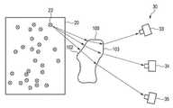
도 14는 본 개시물의 추가적인 양태에 따라 대상자의 각막을 측정하기 위한 장치의 개략도를 도시한다. 장치는, 각막(1201)을 통과하는 이미징 빔 경로(32)를 통해 복수의 (알려진) 시점으로부터 대상자의 홍채(1202)의 이미지 데이터를 포착하도록 구성된 이미지 포착 장치(30); 및 컴퓨팅 장치(40)를 포함할 수 있다. 컴퓨팅 장치는, 각막 및 홍채의 수학적 모델을 포함하는 대상자의 전방 안구 구역의 수학적 모델을 제공하고; 이미지 데이터의 복수의 이미지에 존재하는 홍채의 이미지 특징부를 식별하여 기록하며; 각막의 수학적 모델 및 홍채의 상대 위치를 고려하여, 복수의 시점으로부터 포착된 이미지에서의 홍채의 이미지 특징부의 실제 위치와 복수의 시점으로부터 포착된 이미지에서의 홍채의 이미지 특징부의 예상 위치 사이의 편차를 결정하고; 편차가 최소화되는 방식으로 각막의 수학적 모델의 파라미터를 조정하며; 그리고 각막의 조정된 수학적 모델로부터 각막의 측정 변수를 결정하도록 구성된다.14 shows a schematic diagram of a device for measuring a subject's cornea in accordance with a further aspect of the present disclosure. The apparatus comprises: an
이미지 포착 장치(30)는 도 1에 대해 설명된 것과 동일하거나 유사한 구성을 또 다시 가질 수 있다. 이미지 포착 장치는 각막(1201)을 통과하는 빔 경로를 통해, 홍채(1202)의 이미지 데이터를 포착한다. 알려진 상이한 시점으로부터 이미지 데이터를 포착하기 위해, 알려진 상이한 위치에 카메라(33)가 연속적으로 위치될 수 있다. 이를 위해, 위치 추적 장치(도시되지 않음)가 제공될 수 있다. 대안으로서 또는 이와 더불어, 이미지 데이터를 병렬로 포착하는 복수의 카메라(33, 34)가 제공될 수 있다. 병렬 포착의 장점은 사용자의 눈이 다양한 측정들 중에 움직이지 않는다는 점을 포함한다.The
본 발명자들은, 홍채(1202)의 외형에 관한 지식 없이도, 홍채(1202)와 이미지 포착 장치(30) 사이에 위치된 각막(1201)이 산출될 수 있음을 인식하였다. 홍채(1202)는 알려지지 않은 구조 또는 알려지지 않은 패턴을 갖는다. 그러나, 홍채(1202)는 일반적으로 매우 구조화되어 있다. 본 발명자들은, 홍채의 다수의 이미지 특징부가 식별될 수 있고, 상이한 위치로부터 기록된 이미지 데이터의 복수의 이미지에서의 이들의 위치와 관련하여 후속적으로 평가될 수 있음을 인식하였다. 이를 위해, 각각의 알려진 위치에서 포착되는 이미징 빔 경로(32)로부터 방정식 체계가 설정될 수 있으며, 이로부터 각막(1201)의 형상이 산출될 수 있다.The inventors have recognized that the
도 15 및 도 16은 상이한 시점으로부터 기록된 홍채의 이미지의 알려지지 않은 이미지 특징부의 연관성 또는 상관관계를 도시한다. 도 15의 좌측 이미지는 예를 들어, 도 14의 카메라(33)에 의해 기록된, 제1 위치로부터 각막을 통하는 홍채(1202)의 제1 이미지 표현물(1500a)을 도시한다. 도 16의 우측 이미지는 예를 들어, 도 14의 카메라(34)에 의해 기록된, 제2 위치로부터 각막을 통하는 홍채(1202)의 제2 이미지 표현물(1500b)을 도시한다. 홍채는 일반적으로 매우 구조화된 영역이기 때문에, 홍채(1201)의 동일한 초기 점들(1501a 및 1501b) 사이의 상관관계(1502)를 결정하는 것이 가능하다. 해당 점들의 추가적인 실시예는 1502'로 연결된 참조 부호(1503a 및 1503b)로 명시된다. 이러한 연관성(1500)은 도 16에 도시된 바와 같이, 다수의 이미지(1500a 내지 1500d) 및 영상점에 대해 수행될 수 있다.15 and 16 show the association or correlation of unknown image features of images of the iris recorded from different time points. The left image of FIG. 15 shows a
이러한 상관관계 또는 연관성 분석에 기초하여, 도 14에 도시된 바와 같은 다수의 빔 경로를 재구성하는 것이 가능하다. 도시된 빔 경로(32)로부터 명백한 바와 같이, 홍채(1202) 상의 동일한 영상점으로부터 나오는 광 빔은 상이한 점에서 각막(1201)을 통과하고, 이미지 포착 장치(30)에 의해 상이한 위치에서 포착된다. 이제 이미지 표현물에서 동일한 시작점이 식별되면, 도 14를 참조하여 전술한 바와 같이, 홍채(1202) 상의 시작점과 카메라(33, 34)로의 진입점 사이에 위치된 각막(1201)에 대하여 표현하는 것이 가능하다.Based on this correlation or association analysis, it is possible to reconstruct multiple beam paths as shown in FIG. 14 . As is evident from the illustrated
도 17은 본 발명의 이해를 도울 수 있는, 대상자의 각막을 측정하기 위한 방법의 일 실시형태의 흐름도를 도시한다. 카메라 시스템은 선택적인 선행 단계에서 보정될 수 있다. 그러나, 제조사가 이미 보정을 수행했을 수 있다. 제1 단계(1701)에서, 각막을 통과하는 이미징 빔 경로를 통해 복수의 시점으로부터 대상자의 홍채의 이미지 데이터가 포착될 수 있다. 제2 단계(1702)에서, 각막의 수학적 모델(및 각막에 대한 홍채의 상대 위치)과 함께, 대상자의 전방 안구 구역의 수학적 모델이 제공될 수 있다. 제3 단계(1703)에서, 이미지 데이터의 복수의 이미지(바람직하게는 모든 이미지)에 존재하는 홍채의 이미지 특징부가 식별되어 기록(또는 이미지에 할당)될 수 있다. 제4 단계(1704)에서, 각막의 수학적 모델 및 홍채의 상대 위치를 고려하여, 복수의 시점으로부터 포착된 이미지에서의 홍채의 이미지 특징부의 실제 위치와 복수의 시점으로부터 포착된 이미지에서의 홍채의 이미지 특징부의 예상 위치 사이의 편차를 결정하는 것이 가능하다. 제5 단계(1705)에서, 각막의 수학적 모델의 파라미터는 편차가 최소화되는 방식으로 조정될 수 있다. 단계(1703 및 1704)는 바람직하게는 반복적으로 반복될 수 있다. 제6 단계에서, 이제 각막의 조정된 수학적 모델로부터 각막의 측정 변수를 결정하는 것이 가능하다. 예를 들어, 굴절력 또는 비점수차가 평가될 수 있다.17 depicts a flow diagram of one embodiment of a method for measuring a subject's cornea, which may aid in understanding the present invention. The camera system may be calibrated in an optional preceding step. However, the manufacturer may have already performed the calibration. In a
결론적으로, 본원에 개시된 솔루션은 특히, 측정 체적에 배치된 렌즈 요소의 간소화된 비접촉식 측정을 가능하게 할 수 있거나, 그렇지 않으면 특히, 안구 광학계의 분야에서, 빛에 민감한 사용자의 장애를 감소시키면서, 각막의 비접촉식 측정을 가능하게 할 수 있다.In conclusion, the solution disclosed herein may enable a streamlined, non-contact measurement of a lens element disposed in the measurement volume, in particular, or otherwise reducing the disturbance of light-sensitive users, particularly in the field of ophthalmic optics, while reducing the corneal can enable non-contact measurement of
Claims (21)
Translated fromKorean- 테스트 구조물(21)을 디스플레이하도록 구성된 디스플레이 장치(20);
- 상기 렌즈(100)를 통과하는 이미징 빔 경로(32)를 통해 복수의 시점(31, 31', 31")으로부터 상기 테스트 구조물의 이미지 데이터를 포착하도록 구성된 이미지 포착 장치(30); 및
- 상기 이미지 데이터에 기초하여 상기 렌즈(100)의 3차원 형상을 결정하도록 구성된 컴퓨팅 장치(40)를 포함하며,
상기 컴퓨팅 장치(40)는,
이의 3차원 형태에 기초하여 상기 렌즈(100)의 광학 효과를 산출하도록 추가로 구성되고,
상기 렌즈(100)는 안경 렌즈이며,
상기 컴퓨팅 장치(40)는, 상기 이미지 데이터가 포착되는 측정 위치와 상이한 사용자의 지정된 착용 위치에 대해 상기 안경 렌즈의 광학 효과를 산출하도록 구성되는 것을 특징으로 하는,
측정 체적(200)에 배치된 광학 렌즈(100)의 광학 효과를 측정하기 위한 장치(10).A device (10) for measuring the optical effect of an optical lens (100) disposed in a measuring volume (200), comprising:
- a display device 20 configured to display the test structure 21 ;
- an image capture device 30 configured to capture image data of the test structure from a plurality of viewpoints 31 , 31 ′, 31 ″ via an imaging beam path 32 passing through the lens 100 ; and
- a computing device (40) configured to determine a three-dimensional shape of the lens (100) on the basis of the image data,
The computing device 40,
Further configured to calculate the optical effect of the lens 100 based on its three-dimensional shape,
The lens 100 is a spectacle lens,
wherein the computing device (40) is configured to calculate the optical effect of the spectacle lens for a specified wearing position of the user different from the measurement position at which the image data is captured,
A device (10) for measuring the optical effect of an optical lens (100) disposed in a measuring volume (200).
상기 이미지 포착 장치(30)는 제1 카메라(33) 및 제2 카메라(34)를 포함하며,
상기 제1 카메라(33)는 제1 시점으로부터 제1 이미지 데이터를 포착하도록 구성되고, 상기 제2 카메라(34)는 제2 시점으로부터 제2 이미지 데이터를 포착하도록 구성되며,
상기 컴퓨팅 장치(40)는 상기 제1 및 제2 이미지 데이터에 기초하여 상기 렌즈(100)의 3차원 형상을 결정하도록 구성되는 것을 특징으로 하는, 장치.According to claim 1,
The image capturing device (30) comprises a first camera (33) and a second camera (34),
the first camera 33 is configured to capture first image data from a first time point, the second camera 34 is configured to capture second image data from a second time point,
The computing device (40) is configured to determine a three-dimensional shape of the lens (100) based on the first and second image data.
상기 컴퓨팅 장치(40)는, 집적 방법을 사용하여 상기 렌즈(100)의 3차원 형상을 반복적으로 결정하도록 구성되는 것을 특징으로 하는, 장치.3. The method of claim 1 or 2,
The computing device (40) is characterized in that it is configured to iteratively determine the three-dimensional shape of the lens (100) using an integration method.
상기 컴퓨팅 장치(40)는, 상기 이미지 포착 장치(30)에 진입하는 상기 이미징 빔을 역추적하는 것에 기초하여, 상기 렌즈(100)의 3차원 형상을 결정하도록 구성되는 것을 특징으로 하는, 장치.3. The method of claim 1 or 2,
The computing device (40) is configured to determine a three-dimensional shape of the lens (100) based on tracing back the imaging beam entering the image capturing device (30).
상기 렌즈(100)의 3차원 형상을 결정하는 것은, 표면 요소(106, 108)로의 상기 렌즈의 전면 표면(102) 및 후면 표면(103) 중 적어도 하나의 표면의 분할, 및 상기 표면 요소의 정렬의 결정을 포함하는 것을 특징으로 하는, 장치.3. The method of claim 1 or 2,
Determining the three-dimensional shape of the lens 100 includes partitioning of at least one of the front surface 102 and the rear surface 103 of the lens into surface elements 106 and 108, and alignment of the surface elements. A device, characterized in that it comprises a determination of
상기 컴퓨팅 장치(40)는, 상기 표면 요소의 정렬에 기초하여 상기 렌즈(100)의 전면 표면(102) 및 후면 표면(103)의 3차원 형상을 결정하도록 구현되는 것을 특징으로 하는, 장치.6. The method of claim 5,
The computing device (40) is characterized in that it is implemented to determine the three-dimensional shape of the front surface (102) and the rear surface (103) of the lens (100) based on the alignment of the surface elements.
상기 컴퓨팅 장치(40)는, 상기 렌즈의 전면 표면(102) 또는 후면 표면(103)이 파라미터화 가능한 영역을 갖는 경계 조건을 고려하여, 상기 렌즈(100)의 3차원 형상을 결정하도록 구성되는 것을 특징으로 하는, 장치.3. The method of claim 1 or 2,
that the computing device (40) is configured to determine the three-dimensional shape of the lens (100), taking into account a boundary condition in which the front surface (102) or the rear surface (103) of the lens has a parameterizable area Characterized by the device.
상기 파라미터화 가능한 영역은 구면, 원환체, 구면의 구역, 및 원환체의 구역 중 적어도 하나를 포함하는 것을 특징으로 하는, 장치.8. The method of claim 7,
wherein the parameterizable region comprises at least one of a sphere, a toric, a spherical region, and a toric region.
상기 컴퓨팅 장치(40)는, 상기 렌즈의 하나 이상의 알려진 접촉점(51)을 추가로 고려하여 상기 렌즈(100)의 3차원 형상을 결정하도록 구성되는 것을 특징으로 하는, 장치.3. The method of claim 1 or 2,
Device, characterized in that the computing device (40) is configured to determine the three-dimensional shape of the lens (100) by further taking into account one or more known contact points (51) of the lens.
상기 컴퓨팅 장치(40)는 상기 렌즈(100)의 상기 3차원 형상을 결정하기 위한 경계 조건을 고려하여 상기 렌즈의 3차원 형상을 결정하도록 구성되며,
상기 경계 조건은 측정될 상기 렌즈(100)에 관한 정보를 판독함으로써 결정되는 것을 특징으로 하는, 장치.3. The method of claim 1 or 2,
The computing device 40 is configured to determine the three-dimensional shape of the lens in consideration of a boundary condition for determining the three-dimensional shape of the lens 100,
Device, characterized in that the boundary condition is determined by reading information about the lens (100) to be measured.
상기 경계 조건은 상기 렌즈 상의 코드(140)를 판독함으로써 결정되는, 장치.11. The method of claim 10,
and the boundary condition is determined by reading a code (140) on the lens.
상기 컴퓨팅 장치(40)는, 측정될 상기 렌즈(100)의 공간 굴절률 분포를 결정하도록 추가로 구성되는 것을 특징으로 하는, 장치.3. The method of claim 1 or 2,
The computing device (40) is further configured to determine a spatial refractive index distribution of the lens (100) to be measured.
- 상기 이미지 포착 장치(30)와 상기 디스플레이 장치(20) 사이의 거리를 가변시키도록 구성된 높이 조정 장치(150)를 특징으로 하며,
- 상기 컴퓨팅 장치(40)는, 상기 이미지 포착 장치와 상기 디스플레이 장치 사이의 상이한 거리로부터 포착된 이미지 데이터에 기초하여, 상기 이미지 포착 장치에 의해 포착된 상기 이미징 빔의 빔 방향을 결정하도록 추가로 구성되는, 장치.3. The method of claim 1 or 2,
- a height adjustment device (150) configured to vary the distance between the image capture device (30) and the display device (20),
- the computing device 40 is further configured to determine a beam direction of the imaging beam captured by the image capturing device based on image data captured from different distances between the image capturing device and the display device becoming a device.
- 테스트 구조물(21)을 디스플레이하도록 구성된 디스플레이 장치(20);
- 상기 렌즈(100)를 통과하는 이미징 빔 경로(32)를 통해 복수의 시점(31, 31', 31")으로부터 상기 테스트 구조물의 이미지 데이터를 포착하도록 구성된 이미지 포착 장치(30); 및
- 상기 이미지 데이터에 기초하여 상기 렌즈(100)의 3차원 형상을 결정하고, 이의 상기 3차원 형상에 기초하여 상기 렌즈(100)의 광학 효과를 산출하도록 구성된 컴퓨팅 장치(40)를 포함하며,
컴퓨팅 장치(40)는, 상기 렌즈의 하나 이상의 알려진 접촉점(51)을 고려하여 상기 렌즈(100)의 3차원 형상을 결정하도록 구성되고,
상기 접촉점의 위치는, 상기 렌즈의 형상을 결정하는 알고리즘에 상기 측정 체적에서의 상기 렌즈(100)의 위치에 대한 예상 값을 할당하기 위해 사용되는,
측정 체적(200)에 배치된 광학 렌즈(100)의 광학 효과를 측정하기 위한 장치(10).A device (10) for measuring the optical effect of an optical lens (100) disposed in a measuring volume (200), comprising:
- a display device 20 configured to display the test structure 21 ;
- an image capture device 30 configured to capture image data of the test structure from a plurality of viewpoints 31 , 31 ′, 31 ″ via an imaging beam path 32 passing through the lens 100 ; and
- a computing device (40) configured to determine a three-dimensional shape of the lens (100) on the basis of the image data and calculate an optical effect of the lens (100) based on the three-dimensional shape thereof;
Computing device 40 is configured to determine a three-dimensional shape of said lens 100 taking into account one or more known contact points 51 of said lens,
The position of the contact point is used to assign an expected value for the position of the lens 100 in the measurement volume to an algorithm for determining the shape of the lens.
A device (10) for measuring the optical effect of an optical lens (100) disposed in a measuring volume (200).
- 테스트 구조물(21)을 디스플레이하도록 구성된 디스플레이 장치(20);
- 상기 렌즈(100)를 통과하는 이미징 빔 경로(32)를 통해 복수의 시점(31, 31', 31")으로부터 상기 테스트 구조물의 이미지 데이터를 포착하도록 구성된 이미지 포착 장치(30); 및
- 상기 이미지 데이터에 기초하여 상기 렌즈(100)의 3차원 형상을 결정하고, 이의 상기 3차원 형상에 기초하여 상기 렌즈(100)의 광학 효과를 산출하도록 구성된 컴퓨팅 장치(40)를 포함하며,
상기 컴퓨팅 장치(40)는 경계 조건을 고려하여 상기 렌즈의 3차원 형상을 결정하도록 구성되고,
상기 경계 조건은 측정될 상기 렌즈(100)에 관한 정보를 판독함으로써 결정되며, 상기 경계 조건은 상기 렌즈 상의 코드(140)를 판독함으로써 결정되는,
측정 체적(200)에 배치된 광학 렌즈(100)의 광학 효과를 측정하기 위한 장치(10).A device (10) for measuring the optical effect of an optical lens (100) disposed in a measuring volume (200), comprising:
- a display device 20 configured to display the test structure 21 ;
- an image capture device 30 configured to capture image data of the test structure from a plurality of viewpoints 31 , 31 ′, 31 ″ via an imaging beam path 32 passing through the lens 100 ; and
- a computing device (40) configured to determine a three-dimensional shape of the lens (100) on the basis of the image data and calculate an optical effect of the lens (100) based on the three-dimensional shape thereof;
The computing device 40 is configured to determine the three-dimensional shape of the lens in consideration of boundary conditions,
the boundary condition is determined by reading information about the lens (100) to be measured, the boundary condition being determined by reading a code (140) on the lens;
A device (10) for measuring the optical effect of an optical lens (100) disposed in a measuring volume (200).
- 디스플레이 장치(20)를 통해 디스플레이하기 위한 테스트 구조물(21)을 제공하는 단계;
- 상기 렌즈(100)를 통과하는 이미징 빔 경로(32)를 통해 복수의 시점(31, 31', 31")으로부터 상기 테스트 구조물의 이미지 데이터를 포착하는 단계;
- 이미지 데이터에 기초하여 상기 렌즈(100)의 3차원 형상을 결정하는 단계를 포함하며,
- 이의 상기 3차원 형상에 기초하여 상기 렌즈(100)의 광학 효과를 산출하는 단계를 특징으로 하고,
상기 렌즈(100)는 안경 렌즈이며,
상기 안경 렌즈의 광학 효과는, 상기 이미지 데이터가 포착되는 측정 위치와 상이한 사용자의 지정된 착용 위치에 대해 산출되는,
측정 체적(200)에 배치된 광학 렌즈(100)의 광학 효과를 측정하기 위한 방법(900).A method (900) for measuring the optical effect of an optical lens (100) disposed in a measurement volume (200), the method comprising:
- providing a test structure (21) for display via a display device (20);
- acquiring image data of the test structure from a plurality of viewpoints (31, 31', 31") via an imaging beam path (32) passing through the lens (100);
- Determining a three-dimensional shape of the lens 100 based on the image data,
- Characterized in the step of calculating the optical effect of the lens 100 based on its three-dimensional shape,
The lens 100 is a spectacle lens,
The optical effect of the spectacle lens is calculated for a specified wearing position of the user different from the measurement position at which the image data is captured,
A method 900 for measuring the optical effect of an optical lens 100 disposed in a measurement volume 200 .
- 디스플레이 장치(20)를 통해 디스플레이하기 위한 테스트 구조물(21)을 제공하는 단계;
- 상기 렌즈(100)를 통과하는 이미징 빔 경로(32)를 통해 복수의 시점(31, 31', 31")으로부터 상기 테스트 구조물의 이미지 데이터를 포착하는 단계;
- 이미지 데이터에 기초하여 상기 렌즈(100)의 3차원 형상을 결정하는 단계; 및
- 이의 상기 3차원 형상에 기초하여 상기 렌즈(100)의 광학 효과를 산출하는 단계를 포함하며,
상기 렌즈(100)의 3차원 형상은, 상기 렌즈의 하나 이상의 알려진 접촉점(51)을 고려하여 결정되고,
상기 접촉점의 위치는, 상기 렌즈의 형상을 결정하는 알고리즘에 상기 측정 체적에서의 상기 렌즈(100)의 위치에 대한 예상 값을 할당하기 위해 사용되는,
측정 체적(200)에 배치된 광학 렌즈(100)의 광학 효과를 측정하기 위한 방법(900).A method (900) for measuring the optical effect of an optical lens (100) disposed in a measurement volume (200), the method comprising:
- providing a test structure (21) for display via a display device (20);
- acquiring image data of the test structure from a plurality of viewpoints (31, 31', 31") via an imaging beam path (32) passing through the lens (100);
- determining a three-dimensional shape of the lens 100 based on image data; and
- Calculating the optical effect of the lens 100 based on its three-dimensional shape,
The three-dimensional shape of the lens 100 is determined taking into account one or more known contact points 51 of the lens,
The position of the contact point is used to assign an expected value for the position of the lens 100 in the measurement volume to an algorithm for determining the shape of the lens.
A method 900 for measuring the optical effect of an optical lens 100 disposed in a measurement volume 200 .
- 디스플레이 장치(20)를 통해 디스플레이하기 위한 테스트 구조물(21)을 제공하는 단계;
- 상기 렌즈(100)를 통과하는 이미징 빔 경로(32)를 통해 복수의 시점(31, 31', 31")으로부터 상기 테스트 구조물의 이미지 데이터를 포착하는 단계;
- 이미지 데이터에 기초하여 상기 렌즈(100)의 3차원 형상을 결정하는 단계; 및
- 이의 상기 3차원 형상에 기초하여 상기 렌즈(100)의 광학 효과를 산출하는 단계를 포함하며,
상기 렌즈의 3차원 형상은 상기 렌즈(100)의 상기 3차원 형상을 결정하기 위한 경계 조건을 고려하여 결정되고,
상기 경계 조건은 측정될 상기 렌즈(100)에 관한 정보를 판독함으로써 결정되며, 상기 경계 조건은 상기 렌즈 상의 코드(140)를 판독함으로써 결정되는,
측정 체적(200)에 배치된 광학 렌즈(100)의 광학 효과를 측정하기 위한 방법(900).
A method (900) for measuring the optical effect of an optical lens (100) disposed in a measurement volume (200), the method comprising:
- providing a test structure (21) for display via a display device (20);
- acquiring image data of the test structure from a plurality of viewpoints (31, 31', 31") via an imaging beam path (32) passing through the lens (100);
- determining a three-dimensional shape of the lens 100 based on image data; and
- Calculating the optical effect of the lens 100 based on its three-dimensional shape,
The three-dimensional shape of the lens is determined in consideration of boundary conditions for determining the three-dimensional shape of the lens 100,
the boundary condition is determined by reading information about the lens (100) to be measured, the boundary condition being determined by reading a code (140) on the lens;
A method 900 for measuring the optical effect of an optical lens 100 disposed in a measurement volume 200 .
Priority Applications (1)
| Application Number | Priority Date | Filing Date | Title |
|---|---|---|---|
| KR1020217030412AKR102443550B1 (en) | 2018-04-23 | 2019-04-23 | Method and device for measuring an optical lens for individual wearing situations by a user |
Applications Claiming Priority (3)
| Application Number | Priority Date | Filing Date | Title |
|---|---|---|---|
| EP18168823.5 | 2018-04-23 | ||
| EP18168823.5AEP3561446A1 (en) | 2018-04-23 | 2018-04-23 | Method and device for measuring an optical lens for individual wear situations of a user |
| PCT/EP2019/060346WO2019206893A2 (en) | 2018-04-23 | 2019-04-23 | Method and device for measuring an optical lens for individual wearing situations by an user |
Related Child Applications (1)
| Application Number | Title | Priority Date | Filing Date |
|---|---|---|---|
| KR1020217030412ADivisionKR102443550B1 (en) | 2018-04-23 | 2019-04-23 | Method and device for measuring an optical lens for individual wearing situations by a user |
Publications (2)
| Publication Number | Publication Date |
|---|---|
| KR20200136449A KR20200136449A (en) | 2020-12-07 |
| KR102306581B1true KR102306581B1 (en) | 2021-09-30 |
Family
ID=62046784
Family Applications (2)
| Application Number | Title | Priority Date | Filing Date |
|---|---|---|---|
| KR1020207030591AActiveKR102306581B1 (en) | 2018-04-23 | 2019-04-23 | Method and apparatus for measuring optical lenses for individual wearing situations by a user |
| KR1020217030412AActiveKR102443550B1 (en) | 2018-04-23 | 2019-04-23 | Method and device for measuring an optical lens for individual wearing situations by a user |
Family Applications After (1)
| Application Number | Title | Priority Date | Filing Date |
|---|---|---|---|
| KR1020217030412AActiveKR102443550B1 (en) | 2018-04-23 | 2019-04-23 | Method and device for measuring an optical lens for individual wearing situations by a user |
Country Status (6)
| Country | Link |
|---|---|
| US (2) | US11099100B2 (en) |
| EP (4) | EP3561446A1 (en) |
| KR (2) | KR102306581B1 (en) |
| CN (2) | CN111971524B (en) |
| ES (3) | ES2878192T3 (en) |
| WO (1) | WO2019206893A2 (en) |
Families Citing this family (7)
| Publication number | Priority date | Publication date | Assignee | Title |
|---|---|---|---|---|
| EP3796829A1 (en)* | 2018-05-23 | 2021-03-31 | Alcon Inc. | Measuring a posterior corneal surface of an eye |
| CN114902030B (en)* | 2019-12-26 | 2025-08-19 | 尼德克株式会社 | Spectacle lens measuring device and storage medium |
| EP4321923A4 (en) | 2021-08-05 | 2024-10-30 | Samsung Electronics Co., Ltd. | AUGMENTED REALITY DEVICE AND METHOD FOR DETECTING A USER'S GAZE |
| WO2023014185A1 (en)* | 2021-08-05 | 2023-02-09 | 삼성전자 주식회사 | Augmented reality device and method for detecting gaze of user |
| WO2024128004A1 (en)* | 2022-12-14 | 2024-06-20 | コニカミノルタ株式会社 | Measurement system and measurement method for optical properties of transparent object, and program |
| CN117029704A (en)* | 2023-09-27 | 2023-11-10 | 成都曙创大能科技有限公司 | Multi-lens wire drawing die aperture measurement system |
| EP4555272A1 (en)* | 2023-10-02 | 2025-05-21 | Foundation for Research and Technology - Hellas (Forth) | Method and apparatus for creating a three-dimensional representation of an object, and uses of the apparatus |
Citations (2)
| Publication number | Priority date | Publication date | Assignee | Title |
|---|---|---|---|---|
| US20160109362A1 (en) | 2014-10-21 | 2016-04-21 | Isra Surface Vision Gmbh | Method for determining a local refractive index and device therefor |
| WO2016207412A1 (en) | 2015-06-25 | 2016-12-29 | Carl Zeiss Ag | Measuring individual data of spectacles |
Family Cites Families (30)
| Publication number | Priority date | Publication date | Assignee | Title |
|---|---|---|---|---|
| DE1238690B (en) | 1964-12-11 | 1967-04-13 | Zeiss Carl Fa | Glasses system for lensmeter for checking ready-made glasses |
| US4420228A (en)* | 1980-06-12 | 1983-12-13 | Humphrey Instruments, Inc. | Method and apparatus for analysis of corneal shape |
| CN1069873A (en)* | 1991-08-31 | 1993-03-17 | 凤凰激光系统有限公司 | Ophthalmic diagnostic apparatus and method |
| DE19950790A1 (en)* | 1999-10-21 | 2001-06-21 | Technolas Gmbh | Eye refractive profile developing method for ophthalmic refractive surgery, involves developing refractive course of treatment of eye from determined corneal topography and wavefront aberration |
| ES2214164T3 (en)* | 2001-04-27 | 2009-03-01 | BAUSCH & LOMB INCORPORATED | RECOGNITION AND ALIGNMENT OF IRIS PATTERN. |
| JP2005211631A (en)* | 2004-01-29 | 2005-08-11 | Tomey Corporation | Timing to start measurement in ophthalmologic apparatus |
| US8919958B2 (en)* | 2006-01-20 | 2014-12-30 | Clarity Medical Systems, Inc. | Apparatus and method for operating a real time large diopter range sequential wavefront sensor |
| JP5139792B2 (en) | 2007-12-19 | 2013-02-06 | 株式会社トプコン | Ball shape measuring device |
| EP2101143A1 (en)* | 2008-03-10 | 2009-09-16 | Technische Universität Carolo-Wilhelmina zu Braunschweig | Method and device for recording the shape of transparent refractive objects |
| PT2583618T (en)* | 2011-10-22 | 2018-01-24 | Alcon Pharmaceuticals Ltd | Apparatus for monitoring one or more parameters of the eye |
| DE102011089704B4 (en) | 2011-12-22 | 2020-06-18 | Carl Zeiss Vision International Gmbh | Method for storing information on a spectacle lens, glass or plastic body designed as a spectacle lens blank or semi-finished spectacle lens, device for storing information, method for reading out and reading device |
| US20140039510A1 (en)* | 2012-07-31 | 2014-02-06 | Paul Van Saarloos | Tps tools and methods for the surgical placement of intraocular implants |
| US9332899B2 (en)* | 2012-11-06 | 2016-05-10 | Clarity Medical Systems, Inc. | Electronic eye marking/registration |
| WO2014149625A1 (en)* | 2013-03-15 | 2014-09-25 | Amo Development Llc | Systems and methods for providing anatomical flap centration for an ophthalmic laser treatment system |
| US10369053B2 (en)* | 2013-04-17 | 2019-08-06 | Optimedica Corporation | Corneal topography measurements and fiducial mark incisions in laser surgical procedures |
| AU2014261378B2 (en) | 2013-05-02 | 2017-02-16 | Carl Zeiss Ag | Method and system for determining the spatial structure of an object |
| DE102013219838B4 (en)* | 2013-09-30 | 2015-11-26 | Carl Zeiss Ag | Method and system for determining the spatial structure of an object |
| JP6349701B2 (en)* | 2013-11-29 | 2018-07-04 | 株式会社ニデック | Ophthalmic measuring device |
| EP3079913A4 (en)* | 2013-12-13 | 2017-02-15 | Hewlett-Packard Development Company, L.P. | Printable recording media |
| DE102014005281B4 (en) | 2014-04-09 | 2016-07-14 | Rodenstock Gmbh | Determining the position of at least one spectacle lens in space |
| WO2015177651A1 (en)* | 2014-04-21 | 2015-11-26 | Amo Groningen B.V. | Ophthalmic devices, system and methods that improve peripheral vision |
| DE102014115331A1 (en)* | 2014-10-21 | 2016-04-21 | Isra Surface Vision Gmbh | Method and device for determining a three-dimensional distortion |
| US9649026B2 (en)* | 2014-11-21 | 2017-05-16 | Disney Enterprises, Inc. | Coupled reconstruction of refractive and opaque surfaces |
| NZ773836A (en)* | 2015-03-16 | 2022-07-01 | Magic Leap Inc | Methods and systems for diagnosing and treating health ailments |
| WO2017134275A1 (en)* | 2016-02-05 | 2017-08-10 | Eidgenossische Technische Hochschule Zurich | Methods and systems for determining an optical axis and/or physical properties of a lens and use of the same in virtual imaging and head-mounted displays |
| JP6800597B2 (en)* | 2016-03-30 | 2020-12-16 | キヤノン株式会社 | Controls, control methods and programs |
| CN109690553A (en)* | 2016-06-29 | 2019-04-26 | 醒眸行有限公司 | The system and method for executing eye gaze tracking |
| WO2018052455A1 (en)* | 2016-09-19 | 2018-03-22 | Optimedica Corporation | Systems for opthalmic measurements and laser surgery and systems for surgical planning based thereon |
| JP6823985B2 (en)* | 2016-09-28 | 2021-02-03 | Juki株式会社 | 3D shape measurement method and 3D shape measurement device |
| EP3305176A1 (en)* | 2016-10-04 | 2018-04-11 | Essilor International | Method for determining a geometrical parameter of an eye of a subject |
- 2018
- 2018-04-23EPEP18168823.5Apatent/EP3561446A1/ennot_activeWithdrawn
- 2019
- 2019-04-23CNCN201980027633.2Apatent/CN111971524B/enactiveActive
- 2019-04-23EPEP20194216.6Apatent/EP3783303B1/enactiveActive
- 2019-04-23WOPCT/EP2019/060346patent/WO2019206893A2/ennot_activeCeased
- 2019-04-23ESES19718408Tpatent/ES2878192T3/enactiveActive
- 2019-04-23ESES20194216Tpatent/ES2904779T3/enactiveActive
- 2019-04-23CNCN202210915517.8Apatent/CN115248012B/enactiveActive
- 2019-04-23EPEP21168318.0Apatent/EP3869150B1/enactiveActive
- 2019-04-23KRKR1020207030591Apatent/KR102306581B1/enactiveActive
- 2019-04-23EPEP19718408.8Apatent/EP3746740B1/enactiveActive
- 2019-04-23ESES21168318Tpatent/ES2964477T3/enactiveActive
- 2019-04-23KRKR1020217030412Apatent/KR102443550B1/enactiveActive
- 2020
- 2020-10-20USUS17/074,710patent/US11099100B2/enactiveActive
- 2021
- 2021-05-21USUS17/327,344patent/US20210325276A1/ennot_activeAbandoned
Patent Citations (2)
| Publication number | Priority date | Publication date | Assignee | Title |
|---|---|---|---|---|
| US20160109362A1 (en) | 2014-10-21 | 2016-04-21 | Isra Surface Vision Gmbh | Method for determining a local refractive index and device therefor |
| WO2016207412A1 (en) | 2015-06-25 | 2016-12-29 | Carl Zeiss Ag | Measuring individual data of spectacles |
Also Published As
| Publication number | Publication date |
|---|---|
| EP3783303B1 (en) | 2021-11-03 |
| CN111971524A (en) | 2020-11-20 |
| ES2878192T3 (en) | 2021-11-18 |
| US20210325276A1 (en) | 2021-10-21 |
| EP3746740A2 (en) | 2020-12-09 |
| ES2904779T3 (en) | 2022-04-06 |
| EP3746740B1 (en) | 2021-06-09 |
| KR102443550B1 (en) | 2022-09-16 |
| CN115248012B (en) | 2025-09-12 |
| EP3869150B1 (en) | 2023-10-11 |
| CN111971524B (en) | 2022-07-08 |
| EP3783303A1 (en) | 2021-02-24 |
| EP3869150C0 (en) | 2023-10-11 |
| EP3561446A1 (en) | 2019-10-30 |
| EP3869150A1 (en) | 2021-08-25 |
| WO2019206893A2 (en) | 2019-10-31 |
| WO2019206893A3 (en) | 2019-12-19 |
| ES2964477T3 (en) | 2024-04-08 |
| KR20200136449A (en) | 2020-12-07 |
| US20210033489A1 (en) | 2021-02-04 |
| CN115248012A (en) | 2022-10-28 |
| KR20210119571A (en) | 2021-10-05 |
| US11099100B2 (en) | 2021-08-24 |
Similar Documents
| Publication | Publication Date | Title |
|---|---|---|
| KR102306581B1 (en) | Method and apparatus for measuring optical lenses for individual wearing situations by a user | |
| US11408798B2 (en) | Measuring individual data of spectacles | |
| US20180336720A1 (en) | Systems and Methods For Generating and Using Three-Dimensional Images | |
| JP2010259605A (en) | Gaze measurement apparatus and gaze measurement program | |
| US10620454B2 (en) | System and method of obtaining fit and fabrication measurements for eyeglasses using simultaneous localization and mapping of camera images | |
| US20190369418A1 (en) | Systems and methods for obtaining eyewear information | |
| AU2004325004A1 (en) | Method for designing spectacle lenses taking into account an individual's head and eye movement | |
| CN113711003B (en) | Method and apparatus for measuring the local optical power and/or optical power distribution of an ophthalmic lens | |
| US20180214022A1 (en) | Computer-implemented method for detecting a corneal vertex | |
| CN103229036A (en) | Method of determining at least one refraction characteristic of an ophthalmic lens | |
| JP2017533469A (en) | Apparatus and method for determining optical parameters | |
| WO2019123265A1 (en) | Method and apparatus for the determination of the index of refraction of lens material | |
| JP5173106B2 (en) | Method and apparatus for measuring the transmission of the geometric structure of an optical element | |
| CN110118646B (en) | Glasses parameter detection device and method based on synthetic moire fringe technology | |
| US20250207996A1 (en) | Method and device for determining an imaging quality of an optical system to be tested | |
| Petz et al. | Three-dimensional shape measurement of aspheric refractive optics by pattern transmission photogrammetry | |
| HK1252453B (en) | Apparatus and method for measuring individual data of spectacles and a relevant system |
Legal Events
| Date | Code | Title | Description |
|---|---|---|---|
| E13-X000 | Pre-grant limitation requested | St.27 status event code:A-2-3-E10-E13-lim-X000 | |
| PA0105 | International application | St.27 status event code:A-0-1-A10-A15-nap-PA0105 | |
| A201 | Request for examination | ||
| A302 | Request for accelerated examination | ||
| P11-X000 | Amendment of application requested | St.27 status event code:A-2-2-P10-P11-nap-X000 | |
| P13-X000 | Application amended | St.27 status event code:A-2-2-P10-P13-nap-X000 | |
| PA0201 | Request for examination | St.27 status event code:A-1-2-D10-D11-exm-PA0201 | |
| PA0302 | Request for accelerated examination | St.27 status event code:A-1-2-D10-D17-exm-PA0302 St.27 status event code:A-1-2-D10-D16-exm-PA0302 | |
| PG1501 | Laying open of application | St.27 status event code:A-1-1-Q10-Q12-nap-PG1501 | |
| D13-X000 | Search requested | St.27 status event code:A-1-2-D10-D13-srh-X000 | |
| D14-X000 | Search report completed | St.27 status event code:A-1-2-D10-D14-srh-X000 | |
| E902 | Notification of reason for refusal | ||
| PE0902 | Notice of grounds for rejection | St.27 status event code:A-1-2-D10-D21-exm-PE0902 | |
| T11-X000 | Administrative time limit extension requested | St.27 status event code:U-3-3-T10-T11-oth-X000 | |
| P11-X000 | Amendment of application requested | St.27 status event code:A-2-2-P10-P11-nap-X000 | |
| P13-X000 | Application amended | St.27 status event code:A-2-2-P10-P13-nap-X000 | |
| E701 | Decision to grant or registration of patent right | ||
| PE0701 | Decision of registration | St.27 status event code:A-1-2-D10-D22-exm-PE0701 | |
| GRNT | Written decision to grant | ||
| PA0104 | Divisional application for international application | St.27 status event code:A-0-1-A10-A18-div-PA0104 St.27 status event code:A-0-1-A10-A16-div-PA0104 | |
| PR0701 | Registration of establishment | St.27 status event code:A-2-4-F10-F11-exm-PR0701 | |
| PR1002 | Payment of registration fee | St.27 status event code:A-2-2-U10-U12-oth-PR1002 Fee payment year number:1 | |
| PG1601 | Publication of registration | St.27 status event code:A-4-4-Q10-Q13-nap-PG1601 | |
| PR1001 | Payment of annual fee | St.27 status event code:A-4-4-U10-U11-oth-PR1001 Fee payment year number:4 | |
| PR1001 | Payment of annual fee | St.27 status event code:A-4-4-U10-U11-oth-PR1001 Fee payment year number:5 |