KR102301508B1 - Wearable smart key system for user recognition - Google Patents
Wearable smart key system for user recognitionDownload PDFInfo
- Publication number
- KR102301508B1 KR102301508B1KR1020210081364AKR20210081364AKR102301508B1KR 102301508 B1KR102301508 B1KR 102301508B1KR 1020210081364 AKR1020210081364 AKR 1020210081364AKR 20210081364 AKR20210081364 AKR 20210081364AKR 102301508 B1KR102301508 B1KR 102301508B1
- Authority
- KR
- South Korea
- Prior art keywords
- sensor
- vehicle
- user
- state
- value
- Prior art date
- Legal status (The legal status is an assumption and is not a legal conclusion. Google has not performed a legal analysis and makes no representation as to the accuracy of the status listed.)
- Active
Links
Images


Classifications
- B—PERFORMING OPERATIONS; TRANSPORTING
- B60—VEHICLES IN GENERAL
- B60R—VEHICLES, VEHICLE FITTINGS, OR VEHICLE PARTS, NOT OTHERWISE PROVIDED FOR
- B60R16/00—Electric or fluid circuits specially adapted for vehicles and not otherwise provided for; Arrangement of elements of electric or fluid circuits specially adapted for vehicles and not otherwise provided for
- B60R16/02—Electric or fluid circuits specially adapted for vehicles and not otherwise provided for; Arrangement of elements of electric or fluid circuits specially adapted for vehicles and not otherwise provided for electric constitutive elements
- B60R16/03—Electric or fluid circuits specially adapted for vehicles and not otherwise provided for; Arrangement of elements of electric or fluid circuits specially adapted for vehicles and not otherwise provided for electric constitutive elements for supply of electrical power to vehicle subsystems or for
- B60R16/033—Electric or fluid circuits specially adapted for vehicles and not otherwise provided for; Arrangement of elements of electric or fluid circuits specially adapted for vehicles and not otherwise provided for electric constitutive elements for supply of electrical power to vehicle subsystems or for characterised by the use of electrical cells or batteries
- B—PERFORMING OPERATIONS; TRANSPORTING
- B60—VEHICLES IN GENERAL
- B60R—VEHICLES, VEHICLE FITTINGS, OR VEHICLE PARTS, NOT OTHERWISE PROVIDED FOR
- B60R21/00—Arrangements or fittings on vehicles for protecting or preventing injuries to occupants or pedestrians in case of accidents or other traffic risks
- B60R21/01—Electrical circuits for triggering passive safety arrangements, e.g. airbags, safety belt tighteners, in case of vehicle accidents or impending vehicle accidents
- B60R21/013—Electrical circuits for triggering passive safety arrangements, e.g. airbags, safety belt tighteners, in case of vehicle accidents or impending vehicle accidents including means for detecting collisions, impending collisions or roll-over
- B—PERFORMING OPERATIONS; TRANSPORTING
- B60—VEHICLES IN GENERAL
- B60R—VEHICLES, VEHICLE FITTINGS, OR VEHICLE PARTS, NOT OTHERWISE PROVIDED FOR
- B60R25/00—Fittings or systems for preventing or indicating unauthorised use or theft of vehicles
- B60R25/10—Fittings or systems for preventing or indicating unauthorised use or theft of vehicles actuating a signalling device
- B60R25/1004—Alarm systems characterised by the type of sensor, e.g. current sensing means
- B—PERFORMING OPERATIONS; TRANSPORTING
- B60—VEHICLES IN GENERAL
- B60R—VEHICLES, VEHICLE FITTINGS, OR VEHICLE PARTS, NOT OTHERWISE PROVIDED FOR
- B60R25/00—Fittings or systems for preventing or indicating unauthorised use or theft of vehicles
- B60R25/20—Means to switch the anti-theft system on or off
- B60R25/24—Means to switch the anti-theft system on or off using electronic identifiers containing a code not memorised by the user
- B—PERFORMING OPERATIONS; TRANSPORTING
- B60—VEHICLES IN GENERAL
- B60R—VEHICLES, VEHICLE FITTINGS, OR VEHICLE PARTS, NOT OTHERWISE PROVIDED FOR
- B60R25/00—Fittings or systems for preventing or indicating unauthorised use or theft of vehicles
- B60R25/20—Means to switch the anti-theft system on or off
- B60R25/25—Means to switch the anti-theft system on or off using biometry
- B—PERFORMING OPERATIONS; TRANSPORTING
- B60—VEHICLES IN GENERAL
- B60R—VEHICLES, VEHICLE FITTINGS, OR VEHICLE PARTS, NOT OTHERWISE PROVIDED FOR
- B60R25/00—Fittings or systems for preventing or indicating unauthorised use or theft of vehicles
- B60R25/30—Detection related to theft or to other events relevant to anti-theft systems
- B60R25/34—Detection related to theft or to other events relevant to anti-theft systems of conditions of vehicle components, e.g. of windows, door locks or gear selectors
- B—PERFORMING OPERATIONS; TRANSPORTING
- B60—VEHICLES IN GENERAL
- B60W—CONJOINT CONTROL OF VEHICLE SUB-UNITS OF DIFFERENT TYPE OR DIFFERENT FUNCTION; CONTROL SYSTEMS SPECIALLY ADAPTED FOR HYBRID VEHICLES; ROAD VEHICLE DRIVE CONTROL SYSTEMS FOR PURPOSES NOT RELATED TO THE CONTROL OF A PARTICULAR SUB-UNIT
- B60W40/00—Estimation or calculation of non-directly measurable driving parameters for road vehicle drive control systems not related to the control of a particular sub unit, e.g. by using mathematical models
- B60W40/02—Estimation or calculation of non-directly measurable driving parameters for road vehicle drive control systems not related to the control of a particular sub unit, e.g. by using mathematical models related to ambient conditions
- B60W40/06—Road conditions
- B—PERFORMING OPERATIONS; TRANSPORTING
- B60—VEHICLES IN GENERAL
- B60W—CONJOINT CONTROL OF VEHICLE SUB-UNITS OF DIFFERENT TYPE OR DIFFERENT FUNCTION; CONTROL SYSTEMS SPECIALLY ADAPTED FOR HYBRID VEHICLES; ROAD VEHICLE DRIVE CONTROL SYSTEMS FOR PURPOSES NOT RELATED TO THE CONTROL OF A PARTICULAR SUB-UNIT
- B60W40/00—Estimation or calculation of non-directly measurable driving parameters for road vehicle drive control systems not related to the control of a particular sub unit, e.g. by using mathematical models
- B60W40/08—Estimation or calculation of non-directly measurable driving parameters for road vehicle drive control systems not related to the control of a particular sub unit, e.g. by using mathematical models related to drivers or passengers
- B—PERFORMING OPERATIONS; TRANSPORTING
- B60—VEHICLES IN GENERAL
- B60W—CONJOINT CONTROL OF VEHICLE SUB-UNITS OF DIFFERENT TYPE OR DIFFERENT FUNCTION; CONTROL SYSTEMS SPECIALLY ADAPTED FOR HYBRID VEHICLES; ROAD VEHICLE DRIVE CONTROL SYSTEMS FOR PURPOSES NOT RELATED TO THE CONTROL OF A PARTICULAR SUB-UNIT
- B60W50/00—Details of control systems for road vehicle drive control not related to the control of a particular sub-unit, e.g. process diagnostic or vehicle driver interfaces
- B60W50/08—Interaction between the driver and the control system
- B60W50/14—Means for informing the driver, warning the driver or prompting a driver intervention
- B—PERFORMING OPERATIONS; TRANSPORTING
- B60—VEHICLES IN GENERAL
- B60R—VEHICLES, VEHICLE FITTINGS, OR VEHICLE PARTS, NOT OTHERWISE PROVIDED FOR
- B60R25/00—Fittings or systems for preventing or indicating unauthorised use or theft of vehicles
- B60R25/10—Fittings or systems for preventing or indicating unauthorised use or theft of vehicles actuating a signalling device
- B60R2025/1013—Alarm systems characterised by the type of warning signal, e.g. visual, audible
- B—PERFORMING OPERATIONS; TRANSPORTING
- B60—VEHICLES IN GENERAL
- B60W—CONJOINT CONTROL OF VEHICLE SUB-UNITS OF DIFFERENT TYPE OR DIFFERENT FUNCTION; CONTROL SYSTEMS SPECIALLY ADAPTED FOR HYBRID VEHICLES; ROAD VEHICLE DRIVE CONTROL SYSTEMS FOR PURPOSES NOT RELATED TO THE CONTROL OF A PARTICULAR SUB-UNIT
- B60W40/00—Estimation or calculation of non-directly measurable driving parameters for road vehicle drive control systems not related to the control of a particular sub unit, e.g. by using mathematical models
- B60W40/08—Estimation or calculation of non-directly measurable driving parameters for road vehicle drive control systems not related to the control of a particular sub unit, e.g. by using mathematical models related to drivers or passengers
- B60W2040/0872—Driver physiology
- B—PERFORMING OPERATIONS; TRANSPORTING
- B60—VEHICLES IN GENERAL
- B60W—CONJOINT CONTROL OF VEHICLE SUB-UNITS OF DIFFERENT TYPE OR DIFFERENT FUNCTION; CONTROL SYSTEMS SPECIALLY ADAPTED FOR HYBRID VEHICLES; ROAD VEHICLE DRIVE CONTROL SYSTEMS FOR PURPOSES NOT RELATED TO THE CONTROL OF A PARTICULAR SUB-UNIT
- B60W50/00—Details of control systems for road vehicle drive control not related to the control of a particular sub-unit, e.g. process diagnostic or vehicle driver interfaces
- B60W50/08—Interaction between the driver and the control system
- B60W50/14—Means for informing the driver, warning the driver or prompting a driver intervention
- B60W2050/146—Display means
Landscapes
- Engineering & Computer Science (AREA)
- Mechanical Engineering (AREA)
- Automation & Control Theory (AREA)
- Transportation (AREA)
- Human Computer Interaction (AREA)
- Physics & Mathematics (AREA)
- Mathematical Physics (AREA)
- Lock And Its Accessories (AREA)
Abstract
Description
Translated fromKorean본 발명은 사용자 인식 웨어러블 스마트 키 시스템에 관한 것으로서, 구체적으로는 차량 및 사용자의 상태를 감지하여 차량 및 사용자의 사고를 예방할 수 있는 사용자 인식 웨어러블 스마트키 시스템에 관한 것이다.The present invention relates to a user-recognized wearable smart key system, and more particularly, to a user-recognized wearable smart key system capable of preventing accidents of a vehicle and a user by detecting the state of the vehicle and the user.
웨어러블 기기는 사용자가 이동 또는 활동 중에도 자유롭게 사용할 수 있도록 신체나 의복에 착용 가능하도록 작고 가볍게 개발되어 사용자와 소통가능한 전자기기를 의미하며, 피트니스, 의료, 헬스케어 등 다양한 분야에서 활용되고 있다.A wearable device refers to an electronic device that has been developed to be small and light so that it can be worn on the body or clothes so that the user can freely use it while moving or active, so that it can communicate with the user, and is used in various fields such as fitness, medical care, and healthcare.
한편, 웨어러블 기기는 휴대성을 고려할 때, 차량용 스마트키를 대체하는 장치로 활용될 수 있다. 즉, 웨어러블 기기가 스마트키 기능을 보유한다면, 운전자는 스마트키를 소지해야 하는 불편함을 해소할 수 있으며, 또한, 웨어러블 기기가 갖을 수 있는 기능을 이용하여 사용자의 상태를 감지하고, 차량의 상태를 미리 사용자에 알려 사고를 예방할 수 있도록 할 수 있을 것이다.On the other hand, in consideration of portability, the wearable device may be used as a device replacing the smart key for a vehicle. That is, if the wearable device has a smart key function, the driver can solve the inconvenience of possessing a smart key, and also detect the user's condition using the function that the wearable device can have, and the vehicle condition It will be possible to prevent accidents by notifying users in advance.
그러나, 아직까지 사용자의 상태를 감지하고, 차량의 상태를 미리 운전자에 알려 사고를 예방하는 웨어러블 기기를 이용한 스마트키 개발은 미흡한 실정이다.However, the development of a smart key using a wearable device that detects the user's state and notifies the driver of the vehicle state in advance to prevent accidents is still insufficient.
이에 본 발명의 기술적 과제는 이러한 점에서 착안된 것으로, 본 발명의 목적은 상세하게는 차량에 배치되며 차량의 상태를 감지하는 센서가 차량의 상태를 알리고, 스마트키에 배치되며 사용자의 상태를 감지하는 센서가 사용자의 상태를 감지하여 알림으로써 사용자의 위험 및 사고를 예방하는 사용자 인식 웨어러블 스마트키 시스템을 제공하는 것이다.Accordingly, the technical problem of the present invention was conceived in this regard, and an object of the present invention is in detail disposed in a vehicle and a sensor for detecting the state of the vehicle notifies the state of the vehicle, is placed on the smart key, and detects the state of the user To provide a user-aware wearable smart key system that prevents user risks and accidents by a sensor that detects and notifies the user's status.
본 발명의 다양한 실시 예에 따르면, 사용자 인식 웨어러블 스마트키 시스템은 차량에 배치되고, 상기 차량의 상태를 감지하는 제1 센서부, 상기 차량과 연동되는 스마트키에 배치되고, 사용자의 상태를 감지하는 제2 센서부, 상기 차량에 배치되며, 상기 제1 센서부가 감지한 제1 센서 데이터를 저장하는 데이터 저장부, 상기 차량에 배치되며, 상기 데이터 저장부에 저장된 제1 센서 데이터를 상기 스마트키에 전송하는 제1 통신부, 상기 스마트키에 배치되어 상기 제1 센서데이터를 이용하여 상기 차량의 도난시도 여부를 포함하는 정상 작동 여부 및 충전장치의 이상 여부를 판단하고, 상기 제2 센서부가 감지한 제2 센서 데이터를 이용하여 상기 사용자가 운전이 불가능한 상태인지 여부를 판단하고, 상태 데이터를 생성하는 상태 판단부, 상기 상태 판단부가 생성한 상태 데이터에 따라 상기 차량을 제어하는 차량제어신호를 생성하는 차량 제어신호 생성부, 상기 스마트키에 배치되고 상기 차량제어신호를 상기 차량으로 전송하는 제2 통신부, 상기 차량에 배치되고 상기 차량제어신호에 따라 차량을 제어하는 차량제어모듈 및 상기 스마트키에 배치되고 상기 제1 센서 데이터, 상기 제2 센서 데이터 및 상기 상태 데이터를 표시하는 표시부를 포함한다.According to various embodiments of the present disclosure, a user-recognized wearable smart key system is disposed in a vehicle, a first sensor unit for detecting a state of the vehicle, a smart key interworking with the vehicle, and detecting a user's state A second sensor unit, a data storage unit disposed in the vehicle, for storing the first sensor data sensed by the first sensor unit, a data storage unit disposed in the vehicle, the first sensor data stored in the data storage unit, to the smart key The first communication unit that transmits, is disposed on the smart key and uses the first sensor data to determine whether the vehicle is operating normally, including whether the vehicle is attempted theft or not, and whether the charging device is abnormal, and the second sensor detected by the second sensor 2 A vehicle generating a vehicle control signal for controlling the vehicle according to a state determining unit that determines whether the user is in a state in which driving is impossible by using sensor data, generates state data, and the state data generated by the state determiner A control signal generating unit, a second communication unit disposed in the smart key and transmitting the vehicle control signal to the vehicle, a vehicle control module disposed in the vehicle and controlling the vehicle according to the vehicle control signal, and the smart key, and a display unit for displaying the first sensor data, the second sensor data, and the state data.
본 발명의 다양한 실시 예에 따르면, 상기 제1 센서부는 상기 차량에 가해지는 충격을 감지하는 충격 센서, 상기 차량의 문의 개폐 및 문 손잡이에 가해지는 압력을 감지하는 도어 센서, 상기 차량의 주변 소음을 감지하는 음향센서, 상기 차량의 전장부품의 상태를 감지하는 부품감지 센서 및 상기 차량의 배터리의 상태를 감지하는 배터리 센서를 포함하고, 상기 충격센서가 감지한 이벤트의 패턴에 따라 알림 신호를 전송하는 이벤트 알림부를 더 포함하고, 상기 이벤트 알림부는, 처음 이벤트가 감지되면 상기 스마트키에 알림을 전송하는 제1 알림부 및 반복적인 이벤트가 가해지면 상기 스마트키에 알림을 전송하는 제2 알림부를 포함할 수 있다.According to various embodiments of the present disclosure, the first sensor unit detects an impact sensor that detects an impact applied to the vehicle, a door sensor that detects the pressure applied to the opening and closing of a door of the vehicle and a door handle, and an ambient noise of the vehicle. Comprising a sound sensor for detecting, a component detecting sensor for detecting the state of the electric part of the vehicle, and a battery sensor for detecting the state of the battery of the vehicle, transmitting a notification signal according to the pattern of the event detected by the shock sensor It further comprises an event notification unit, wherein the event notification unit, the first notification unit for transmitting a notification to the smart key when an event is detected for the first time, and a second notification unit for transmitting a notification to the smart key when a repetitive event is applied. can
본 발명의 다양한 실시 예에 따르면, 사용자 인식 웨어러블 스마트키 시스템은 상기 상태 판단부는 상기 스마트키가 상기 도어센서의 작동범위 내에 없으면서 상기 차량의 문의 개폐가 감지되는 경우 및 상기 스마트키가 상기 도어센서의 작동범위 내에 없으면서 시동 모듈의 작동이 감지되는 경우 비정상 작동으로 인식하고, 상기 도어센서의 작동범위는 아래의 식으로 정의되고, 도어센서의 작동 변수가 0보다 작으면 정상작동 범위이고, 도어센서의 작동 변수가 0보다 크거나 같으면 비정상 작동 범위일 수 있다.According to various embodiments of the present disclosure, in the user-recognized wearable smart key system, when the state determining unit detects opening and closing of the vehicle door while the smart key is not within the operating range of the door sensor, and the smart key is the door sensor If the operation of the starting module is detected without being within the operating range, it is recognized as an abnormal operation, and the operating range of the door sensor is defined by the following equation. If the operating variable is greater than or equal to zero, it may be an abnormal operating range.

(여기서,


본 발명의 다양한 실시 예에 따르면, 상기 상태 판단부는 상기 충격센서가 측정한 충격의 값이 소정의 충격의 값보다 큰 경우 및 상기 충격 센서에 처음 충격이 감지된 후 일정 횟수 이상 충격이 반복되어 감지되는 경우 비정상 작동으로 인식하고, 상기 충격 센서는 소정의 시간 주기로 상기 차량에 가해지는 충격을 감지하고, 소정의 충격의 값보다 큰 값으로 감지되는 경우 상기 제1 알림부가 상기 스마트키에 알림을 전송하고, 상기 제1 알림부가 알림을 전송하는 횟수가 소정의 횟수 이상인 경우 상기 제2 알림부가 상기 스마트키에 알림을 전송할 수 있다.According to various embodiments of the present disclosure, when the value of the shock measured by the shock sensor is greater than a predetermined shock value, and the shock sensor repeats the shock a certain number of times or more after the first shock is sensed by the shock sensor. is recognized as an abnormal operation, the shock sensor detects an impact applied to the vehicle at a predetermined time period, and when a value greater than a predetermined impact value is detected, the first notification unit sends a notification to the smart key and the second notification unit may transmit a notification to the smart key when the number of times the first notification unit transmits the notification is equal to or greater than a predetermined number of times.
본 발명의 다양한 실시 예에 따르면, 상기 음향센서가 작동하면서 상기 충격센서에 충격이 감지되는 경우 비정상 작동으로 인식하고, 상기 음향센서의 작동은 아래의 식에 의해 결정되고, 음향센서 작동 변수가 0보다 작은 값이면 음향센서가 작동하지 않고, 음향센서 작동 변수가 0보다 큰 값이면 음향센서가 작동할 수 있다.According to various embodiments of the present disclosure, when an impact is detected by the impact sensor while the sound sensor operates, it is recognized as an abnormal operation, and the operation of the sound sensor is determined by the following equation, and the sound sensor operation variable is 0 If the value is smaller than the value, the acoustic sensor does not operate, and if the value of the acoustic sensor operation parameter is greater than 0, the acoustic sensor may operate.

(여기서, Z는 음향센서 작동변수,
본 발명의 다양한 실시 예에 따르면, 상기 상태 판단부는 상기 충격센서가 측정한 충격의 값이 소정의 충격의 값보다 큰 경우 및 상기 충격 센서에 처음 충격이 감지된 후 일정 횟수 이상 충격이 반복되어 감지되는 경우 비정상 작동으로 인식하고, 상기 충격 센서는 소정의 시간 주기로 상기 차량에 가해지는 충격을 감지하고, 소정의 충격의 값보다 큰 값으로 감지되는 경우 상기 제1 알림부가 상기 스마트키에 알림을 전송하고, 상기 제1 알림부가 알림을 전송하는 횟수가 소정의 횟수 이상인 경우 상기 제2 알림부가 상기 스마트키에 알림을 전송할 수 있다.According to various embodiments of the present disclosure, when the value of the shock measured by the shock sensor is greater than a predetermined shock value, and the shock sensor repeats the shock a certain number of times or more after the first shock is sensed by the shock sensor. is recognized as an abnormal operation, the shock sensor detects an impact applied to the vehicle at a predetermined time period, and when a value greater than a predetermined impact value is detected, the first notification unit sends a notification to the smart key and the second notification unit may transmit a notification to the smart key when the number of times the first notification unit transmits the notification is equal to or greater than a predetermined number of times.
본 발명의 다양한 실시 예에 따르면, 상기 음향센서가 작동하면서 상기 충격센서에 충격이 감지되는 경우 비정상 작동으로 인식하고,According to various embodiments of the present disclosure, when an impact is detected by the impact sensor while the sound sensor operates, it is recognized as an abnormal operation,
상기 음향센서의 작동은 아래의 식에 의해 결정되고, 음향센서 작동 변수가 0보다 작은 값이면 음향센서가 작동하지 않고, 음향센서 작동 변수가 0보다 큰 값이면 음향센서가 작동할 수 있다.The operation of the acoustic sensor is determined by the following equation, and when the acoustic sensor operation variable is a value less than 0, the acoustic sensor does not operate, and when the acoustic sensor operation parameter is a value greater than 0, the acoustic sensor may operate.

(여기서, Z는 음향센서 작동변수,
본 발명의 다양한 실시 예에 따르면, 상기 충전장치의 이상 여부는 아래의 식에 의해 결정되고, 차량의 전력 상태 변수의 값이 1이면 충전 장치에 이상이 없는 것으로 판단하고, 차량의 전력 상태 변수의 값이 0이면 충전 장치에 이상이 있는 것으로 판단할 수 있다.According to various embodiments of the present disclosure, whether or not the charging device is abnormal is determined by the following equation, and when the value of the power state variable of the vehicle is 1, it is determined that there is no abnormality in the charging device, and the If the value is 0, it may be determined that there is an abnormality in the charging device.

(여기서,


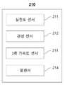
본 발명의 다양한 실시 예에 따르면, 상기 제2 센서부는, 상기 사용자의 심전도 신호를 측정하기 위한 심전도 센서, 상기 사용자의 움직임의 변화를 측정하기 위한 관성센서, 상기 사용자의 움직임에 따른 가속도 측정을 위한 3축 가속도 센서 및 상기 사용자의 혈압을 측정하기 위한 광센서를 포함하고, 상기 사용자가 상기 차량에 접근하는 경우 상기 제2 센서부가 상기 사용자상태를 측정하고, 상기 사용자가 운전 중일 경우 소정의 시간 간격으로 상기 사용자상태를 측정할 수 있다.According to various embodiments of the present disclosure, the second sensor unit may include an electrocardiogram sensor for measuring the user's electrocardiogram signal, an inertial sensor for measuring a change in the user's movement, and an acceleration measurement according to the user's movement. a three-axis acceleration sensor and an optical sensor for measuring the user's blood pressure, wherein the second sensor unit measures the user's state when the user approaches the vehicle, and a predetermined time interval when the user is driving can measure the user state.
본 발명의 다양한 실시 예에 따르면, 상기 제2 센서부의 각 센서들의 초기 설정 값 및 변화율을 아래의 식에 의해 정의될 수 있다.According to various embodiments of the present disclosure, the initial set value and change rate of each sensor of the second sensor unit may be defined by the following equation.


(여기서,


본 발명의 다양한 실시 예에 따르면, 상기 제2 센서부의 각 센서들의 측정 값으로 판단한 사용자의 상태 값은 아래의 식에 의해 정의될 수 있다.According to various embodiments of the present disclosure, the user's state value determined by the measurement values of the respective sensors of the second sensor unit may be defined by the following equation.


(여기서,


본 발명의 다양한 실시 예에 따르면, 상기 사용자의 현재 상태는 아래의 식으로 정의되고, 사용자 현재 상태 값이 0이면 정상이고, 1이면 비정상으로 판단할 수 있다.According to various embodiments of the present disclosure, the current state of the user is defined by the following equation, and if the current state of the user is 0, it may be determined to be normal, and if it is 1, it may be determined to be abnormal.

(여기서, S는 사용자의 현재 상태 값이고,


본 발명의 다양한 실시 예에 따르면, 상기 차량 제어신호 생성부는, 상기


본 발명의 다양한 실시 예에 따르면, 상기 제1 센서 데이터 및 상기 제2 센서 데이터를 수신 받는 사용자 단말기를 더 포함할 수 있다.According to various embodiments of the present disclosure, a user terminal receiving the first sensor data and the second sensor data may be further included.
상기와 같은 본 발명에 따르면, 사용자의 상태를 측정한 센서 데이터를 정밀하게 분석함으로써 운전하기에 부적합한 운전자를 운전할 수 없도록 조치하여 교통사고를 미연에 방지할 수 있는 장점이 있다.According to the present invention as described above, there is an advantage in that it is possible to prevent a traffic accident in advance by taking measures so that a driver unsuitable for driving cannot be driven by precisely analyzing the sensor data measuring the user's condition.
또한, 본 발명에 따르면, 차량의 상태를 측정한 센서 데이터를 정밀하게 분석하여 차량의 도난시도를 판단하고, 사용자에게 신속하게 전달하여 차량의 도난을 미연에 방지할 수 있다는 장점이 있다.In addition, according to the present invention, there is an advantage that theft of the vehicle can be prevented in advance by precisely analyzing the sensor data measuring the state of the vehicle, determining the vehicle theft attempt, and promptly delivering it to the user.
또한, 본 발명에 따르면, 차량의 충전장치 이상을 사용자가 미리 알 수 있어 차량을 편리하게 관리할 수 있다는 장점이 있다.In addition, according to the present invention, there is an advantage that the user can know in advance the abnormality of the charging device of the vehicle, so that the vehicle can be conveniently managed.
또한 본 발명에 따르면, 사용자의 상태를 정밀하게 분석하여 일상 및 운전 중인 사용자의 상태를 인식하고, 건강상태 악화 등의 돌발 상황이 발생하여 운전이 불가능해진 운전자를 구원기관에 신속히 전달할 수 있어 운전 중 및 보행 등 일상의 위험상태 등 이상이 발생한 운전자를 신속하게 구조할 수 있다는 장점이 있다.In addition, according to the present invention, it is possible to accurately analyze the user's condition to recognize the user's daily life and driving condition, and to quickly deliver the driver who is unable to drive due to an unexpected situation such as deterioration of health to a rescue organization, so that the driver can be quickly transferred to a rescue organization while driving. And it has the advantage of being able to quickly rescue a driver who has an abnormality such as a dangerous state of everyday life such as walking.
도 1은 본 발명의 일 실시 예에 따른 사용자 인식 웨어러블 스마트키 시스템을 나타내는 블럭도이다.
도 2는 일 실시 예에 따른 사용자 인식 웨어러블 스마트키 시스템의 차량을 나타내는 블럭도이다.
도 3은 일 실시 예에 따른 상기 차량의 제1 센서부를 나타내는 블록도이다.
도 4는 일 실시예에 따른 사용자 인식 웨어러블 스마트키 시스템의 스마트키를 나타내는 블럭도이다.
도 5는 일 실시예에 따른 상기 스마트키의 제2 센서부를 나타내는 블럭도이다.
도 6은 일 실시예에 따른 사용자 인식 웨어러블 스마트키 시스템이 차량에 도난시도가 있는지 판단하고 사용자에 알리는 과정을 나타내는 흐름도이다.
도 7은 일 실시예에 따른 사용자 인식 웨어러블 스마트키 시스템이 사용자가 운전이 불가능한 상태인지 판단하고 차량을 제어하는 과정을 나타내는 흐름도이다.
도 8 및 도 9는 일 실시 예에 따른 사용자 인식 웨어러블 스마트키 시스템의 데이터의 흐름을 설명하는 도면이다.1 is a block diagram illustrating a user-recognized wearable smart key system according to an embodiment of the present invention.
2 is a block diagram illustrating a vehicle of a user-recognized wearable smart key system according to an embodiment.
3 is a block diagram illustrating a first sensor unit of the vehicle according to an exemplary embodiment.
4 is a block diagram illustrating a smart key of a user-recognized wearable smart key system according to an embodiment.
5 is a block diagram illustrating a second sensor unit of the smart key according to an embodiment.
6 is a flowchart illustrating a process in which a user-recognized wearable smart key system determines whether a vehicle has been stolen and notifies a user according to an embodiment.
7 is a flowchart illustrating a process in which a user-recognized wearable smart key system determines whether a user is in an impossible state to drive and controls a vehicle according to an embodiment.
8 and 9 are diagrams for explaining a data flow of a user-recognized wearable smart key system according to an embodiment.
이하 본 발명의 다양한 실시 예를 첨부된 도면을 참조하여 상세히 설명한다. 그리고, 본 발명의 실시 예를 설명함에 있어서, 관련된 공지기능 혹은 구성에 대한 구체적인 설명이 본 발명의 요지를 불필요하게 흐릴 수 있다고 판단된 경우 그 상세한 설명은 생략한다. 그리고 후술되는 용어들은 본 발명의 기능을 고려하여 정의된 용어들로서 이는 사용자, 운용자의 의도 또는 관례 등에 따라 달라질 수 있다. 그러므로 그 정의는 본 명세서 전반에 걸친 내용을 토대로 내려져야 할 것이다.Hereinafter, various embodiments of the present invention will be described in detail with reference to the accompanying drawings. In the description of the embodiment of the present invention, if it is determined that a detailed description of a related known function or configuration may unnecessarily obscure the gist of the present invention, the detailed description thereof will be omitted. In addition, the terms to be described later are terms defined in consideration of the functions of the present invention, which may vary according to the intention or custom of the user or operator. Therefore, the definition should be made based on the content throughout this specification.
본 발명의 바람직한 실시예에 대하여 첨부한 도면을 참조하여 설명하면 다음과 같다. 그러나 본 발명은 이하에서 개시되는 실시예에 한정되는 것이 아니라 서로 다른 다양한 형태로 구현될 수 있으며, 단지 본 실시예는 본 발명의 개시가 완전하도록 하며 통상의 지식을 가진 자에게 발명의 범주를 완전하게 알려주기 위해 제공되는 것이다.A preferred embodiment of the present invention will be described with reference to the accompanying drawings as follows. However, the present invention is not limited to the embodiments disclosed below, but may be implemented in various different forms, only this embodiment allows the disclosure of the present invention to be complete and the scope of the invention to those of ordinary skill in the art completely It is provided to inform you.
본 문서의 다양한 실시예들은 기기(machine)(예: 컴퓨터)로 읽을 수 있는 저장 매체(machine-readable storage media))에 저장된 명령어를 포함하는 소프트웨어(예: 프로그램)로 구현될 수 있다. 기기는, 저장 매체로부터 저장된 명령어를 호출하고, 호출된 명령어에 따라 동작이 가능한 장치로서, 개시된 실시예들에 따른 전자 장치(예: 서버)를 포함할 수 있다. 명령은 컴파일러 또는 인터프리터에 의해 생성 또는 실행되는 코드를 포함할 수 있다. 기기로 읽을 수 있는 저장매체는, 비일시적(non-transitory) 저장매체의 형태로 제공될 수 있다. 여기서, '비일시적'은 저장매체가 신호(signal)를 포함하지 않으며 실재(tangible)한다는 것을 의미할 뿐 데이터가 저장매체에 반영구적 또는 임시적으로 저장됨을 구분하지 않는다.Various embodiments of the present document may be implemented as software (eg, a program) including instructions stored in a machine-readable storage medium (eg, a computer). The device is a device capable of calling a stored command from a storage medium and operating according to the called command, and may include an electronic device (eg, a server) according to the disclosed embodiments. Instructions may include code generated or executed by a compiler or interpreter. The device-readable storage medium may be provided in the form of a non-transitory storage medium. Here, 'non-transitory' means that the storage medium does not include a signal and is tangible, and does not distinguish that data is semi-permanently or temporarily stored in the storage medium.
일시예에 따르면, 본 문서에 개시된 다양한 실시예들에 따른 방법은 컴퓨터 프로그램 제품(computer program product)에 포함되어 제공될 수 있다. 컴퓨터 프로그램 제품은 상품으로서 판매자 및 구매자 간에 거래될 수 있다. 컴퓨터 프로그램 제품은 기기로 읽을 수 있는 저장 매체(예: compact disc read only memory (CD-ROM))의 형태로, 또는 어플리케이션 스토어(예: 플레이 스토어TM)를 통해 온라인으로 배포될 수 있다. 온라인 배포의 경우에, 컴퓨터 프로그램 제품의 적어도 일부는 제조사의 서버, 어플리케이션 스토어의 서버, 또는 중계 서버의 메모리와 같은 저장 매체에 적어도 일시 저장되거나, 임시적으로 생성될 수 있다.According to an example, the method according to various embodiments disclosed in the present document may be included and provided in a computer program product. Computer program products may be traded between sellers and buyers as commodities. The computer program product may be distributed in the form of a machine-readable storage medium (eg, compact disc read only memory (CD-ROM)) or online through an application store (eg, Play Store™). In the case of online distribution, at least a part of the computer program product may be temporarily stored or temporarily generated in a storage medium such as a memory of a server of a manufacturer, a server of an application store, or a relay server.
다양한 실시예들에 따른 구성 요소(예: 모듈 또는 프로그램) 각각은 단수 또는 복수의 개체로 구성될 수 있으며, 전술한 해당 서브 구성 요소들 중 일부 서브 구성 요소가 생략되거나, 또는 다른 서브 구성 요소가 다양한 실시예에 더 포함될 수 있다. 대체적으로 또는 추가적으로, 일부 구성 요소들(예: 모듈 또는 프로그램)은 하나의 개체로 통합되어, 통합되기 이전의 각각의 해당 구성 요소에 의해 수행되는 기능을 동일 또는 유사하게 수행할 수 있다. 다양한 실시예들에 따른, 모듈, 프로그램 또는 다른 구성 요소에 의해 수행되는 동작들은 순차적, 병렬적, 반복적 또는 휴리스틱하게 실행되거나, 적어도 일부 동작이 다른 순서로 실행되거나, 생략되거나, 또는 다른 동작이 추가될 수 있다.Each of the components (eg, a module or a program) according to various embodiments may be composed of a singular or a plurality of entities, and some sub-components of the aforementioned sub-components may be omitted, or other sub-components may be It may be further included in various embodiments. Alternatively or additionally, some components (eg, a module or a program) may be integrated into a single entity to perform the same or similar functions performed by each corresponding component prior to integration. According to various embodiments, operations performed by a module, program, or other component are executed sequentially, parallel, iteratively, or heuristically, or at least some operations are executed in a different order, are omitted, or other operations are added. can be
다른 정의가 없다면, 본 명세서에서 사용되는 모든 용어(기술 및 과학적 용어를 포함)는 본 발명이 속하는 기술분야에서 통상의 지식을 가진 자에게 공통적으로 이해될 수 있는 의미로 사용될 수 있을 것이다. 또 일반적으로 사용되는 사전에 정의되어 있는 용어들은 명백하게 특별히 정의되어 있지 않는 한 이상적으로 또는 과도하게 해석되지 않는다.Unless otherwise defined, all terms (including technical and scientific terms) used herein may be used with the meaning commonly understood by those of ordinary skill in the art to which the present invention belongs. In addition, terms defined in a commonly used dictionary are not to be interpreted ideally or excessively unless clearly defined in particular.
본 명세서에서 사용된 용어는 실시예들을 설명하기 위한 것이며 본 발명을 제한하고자 하는 것은 아니다. 본 명세서에서, 단수형은 문구에서 특별히 언급하지 않는 한 복수형도 포함한다. 명세서에서 사용되는 "포함한다(comprises)" 및/또는 "포함하는(comprising)"은 언급된 구성요소 외에 하나 이상의 다른 구성요소의 존재 또는 추가를 배제하지 않는다.The terminology used herein is for the purpose of describing the embodiments and is not intended to limit the present invention. In this specification, the singular also includes the plural unless specifically stated otherwise in the phrase. As used herein, “comprises” and/or “comprising” does not exclude the presence or addition of one or more other components in addition to the stated components.
도 1 은 본 발명의 일 실시예에 따른 사용자 인식 웨어러블 스마트키 시스템을 나타내는 블럭도이다. 도 2는 본 발명의 일 실시예에 따른 사용자 인식 웨어러블 스마트키 시스템의 차량을 나타내는 블록도이다. 도 3은 본 발명의 일 실시예에 따른 사용자 인식 웨어러블 스마트키 시스템의 차량의 제1 센서부를 나타내는 블록도이다. 도 4는 본 발명의 일 실시예에 따른 사용자 인식 웨어러블 스마트키 시스템의 스마트키를 나타내는 블럭도이다. 도 5는 본 발명의 일 실시예에 따른 사용자 인식 웨어러블 스마트키 시스템의 스마트키의 제2 센서부를 나타내는 블럭도이다.1 is a block diagram illustrating a user-recognized wearable smart key system according to an embodiment of the present invention. 2 is a block diagram illustrating a vehicle of a user-recognized wearable smart key system according to an embodiment of the present invention. 3 is a block diagram illustrating a first sensor unit of a vehicle of a user-recognized wearable smart key system according to an embodiment of the present invention. 4 is a block diagram illustrating a smart key of a user-recognized wearable smart key system according to an embodiment of the present invention. 5 is a block diagram illustrating a second sensor unit of a smart key of a user-recognized wearable smart key system according to an embodiment of the present invention.
도 1 내지 도 5를 참조하면, 일 실시 예에 따른 사용자 인식 웨어러블 스마트키 시스템은 차량(100) 및 스마트키(200)를 포함한다. 상기 차량(100)은 제1 센서부(110), 데이터 저장부(120), 제1 통신부(130) 및 차량제어모듈(140)을 포함할 수 있다. 상기 스마트키(200)는 제2 센서부(210), 제2 통신부(220), 상태 판단부(230), 차량 제어신호 생성부(240) 및 표시부(250)를 포함할 수 있다.1 to 5 , a user-recognized wearable smart key system according to an embodiment includes a
제1 센서부(110)는 차량에 배치되어 차량의 상태를 감지할 수 있다. 보다 상세하게 상기 제1 센서부(110)는 상기 차량에 가해지는 충격을 감지하기 위한 충격센서(111), 상기 차량문의 개폐 및 문 손잡이에 가해지는 압력을 감지하는 도어센서(112), 상기 차량의 주변 소음을 감지하는 음향센서(113), 상기 차량의 전장부품의 상태를 감지하는 부품감지센서(114), 상기 차량의 배터리의 상태를 감지하는 배터리 센서(115), 상기 충격센서가 감지한 이벤트의 패턴에 따라 알림 신호를 전송하는 이벤트 알림부(116)를 포함할 수 있다. 이벤트알림부(116)는 처음 이벤트가 감지되면 상기 스마트키에 알림을 전송하는 제1 알림부 및 반복적인 이벤트가 가해지면 상기 스마트키에 알림을 전송하는 제2 알림부를 포함할 수 있다. 본 발명은 제1 센서부(100)가 충격센서(111), 도어센서(112), 음향센서(113), 부품감지센서(114) 및 배터리센서(115)를 포함하는 것으로 설명하였으나, 이에 한정되는 것은 아니며, 상기 제1 센서부(100)는 상기 센서들 외 차량의 상태를 감지하는 다양한 센서들을 포함할 수 있다.The
제2 센서부(210)는 상기 차량과 연동되는 스마트키에 배치되어 사용자의 상태를 감지할 수 있다. 보다 상세하게 제2 센서부는 상기 사용자의 심전도 신호를 측정하는 심전도 센서(211), 상기 사용자의 움직임의 변화를 측정하는 관성센서(212), 상기 사용자의 움직임에 따른 가속도 측정하는 3축 가속도 센서(213) 및 상기 사용자의 혈압을 측정하는 광센서(214)를 포함할 수 있다. 본 발명은 제2 센서부(200)가 심전도 센서(211), 관성센서(112), 3축 가속도 센서(113) 및 광센서(114)를 포함하는 것으로 설명하였으나, 이에 한정되는 것은 아니며, 상기 제2 센서부(100)는 상기 센서들 외 사용자의 상태를 감지하기 위한 다양한 센서들을 포함할 수 있다. 또한, 제2 센서부(210)는 상기 사용자가 상기 차량에 접근하는 경우 상기 제2 센서부(210)가 상기 사용자상태를 측정하고, 상기 사용자가 운전 중일 경우 소정의 시간 간격으로 상기 사용자상태를 측정할 수 있다.The
데이터 저장부(120)는 상기 제1 센서부(110)가 감지한 차량의 상태를 포함하는 제1 센서 데이터를 저장할 수 있다. 즉, 데이터 저장부(120)는 충격센서의 측정 값, 도어센서의 측정 값, 음향센서의 측정 값, 부품감지센서의 측정 값 및 배터리 센서의 측정값 등 제1 센서부에서 측정한 차량의 상태를 저장할 수 있다.The
제1 통신부(130)는 상기 차량(100)에 배치되어 상기 데이터 저장부에 저장된 제1 센서 데이터를 상기 스마트키에 전송할 수 있다. 예를 들면 블루투스, RFID, Wi-Fi 통신 등을 이용하는 것이 바람직하나, 이에 한정되는 것은 아니다.The
상태 판단부(230)는 상기 스마트키에 배치되어 상기 제1 센서데이터를 이용하여 상기 차량의 도난시도 여부를 포함하는 정상 작동 여부 및 충전장치의 이상 여부를 판단하고, 상기 제2 센서부가 감지한 제2 센서 데이터를 이용하여 상기 사용자가 운전이 불가능한 상태인지 여부를 판단하고, 상태 데이터를 생성할 수 있다.The
차량 제어신호 생성부(240)는 상기 상태 판단부가 생성한 상태 데이터에 따라 상기 차량을 제어하는 차량제어신호를 생성할 수 있다.The vehicle control
삭제delete
삭제delete
삭제delete
삭제delete
삭제delete
예를 들어, 상태 판단부(230)는 상기 충격센서가 측정한 충격의 값이 소정의 충격의 값보다 큰 경우 및 상기 충격 센서에 처음 충격이 감지된 후 일정 횟수 이상 충격이 반복되어 감지되는 경우 비정상 작동으로 인식하고, 상기 충격 센서는 소정의 시간 주기로 상기 차량에 가해지는 충격을 감지하고, 소정의 충격의 값보다 큰 값으로 감지되는 경우 상기 제1 알림부가 상기 스마트키에 알림을 전송하고, 상기 제1 알림부가 알림을 전송하는 횟수가 소정의 횟수 이상인 경우 상기 제2 알림부가 상기 스마트키에 알림을 전송할 수 있다.For example, when the value of the shock measured by the shock sensor is greater than a predetermined shock value, and when the shock is repeatedly sensed a certain number of times or more after the first shock is sensed by the shock sensor Recognized as an abnormal operation, the shock sensor detects an impact applied to the vehicle at a predetermined time period, and when a value greater than a predetermined impact value is detected, the first notification unit sends a notification to the smart key, When the number of times the first notification unit transmits a notification is greater than or equal to a predetermined number of times, the second notification unit may transmit a notification to the smart key.
상기 충격 센서(111)가 시간에 따라 측정한 충격의 값은 아래의 수학식2에 의해 정의될 수 있다.The value of the impact measured by the
수학식 2Equation 2

여기서,

상기 음향센서가 작동하면서 상기 충격센서에 충격이 감지되는 경우 비정상 작동으로 인식하고, 상기 음향센서(113)의 작동은 아래의 수학식 3에 의해 결정되고, 음향센서 작동 변수가 0보다 작은 값이면 음향센서가 작동하지 않고, 음향센서 작동 변수가 0보다 큰 값이면 음향센서가 작동할 수 있다.When an impact is detected by the shock sensor while the sound sensor operates, it is recognized as an abnormal operation, and the operation of the
수학식 3Equation 3

(여기서, Z는 음향센서 작동변수,
예를 들어, 상태 판단부(230)는 상기 충전장치의 이상 여부는 아래의 수학식 4에 의해 결정되고, 차량의 전력 상태 변수의 값이 1이면 충전 장치에 이상이 없으로 것으로 판단하고, 차량의 전력 상태 변수의 값이 0이면 충전 장치에 이상이 있는 것으로 판단할 수 있다.For example, the
수학식 4Equation 4

(여기서,


예를 들어, 상기 심전도 센서의 초기 설정 값 및 변화율을 아래의 수학식 5에 의해 정의될 수 있다.For example, the initial set value and change rate of the electrocardiogram sensor may be defined by Equation 5 below.
수학식 5Equation 5


(여기서,


또한, 상기 심전도 센서(211)의 측정 값은 아래의 수학식 6에 의해 정의될 수 있다.In addition, the measured value of the
수학식 6Equation 6

(여기서,

즉, 심전도 센서의 측정값이 심전도 센서의 초기 설정 값의 50%를 초과하면 심전도 센서의 값이 비정상이라고 판단할 수 있다.That is, when the measured value of the ECG sensor exceeds 50% of the initial set value of the ECG sensor, it may be determined that the value of the ECG sensor is abnormal.
예를 들어, 상기 관성 센서(212)의 초기 설정 값, 변화율 및 관성 센서(212)의 측정 값을 아래의 수학식 7에 의해 정의될 수 있다.For example, the initial setting value, the rate of change, and the measured value of the
수학식 7Equation 7


(여기서,


또한, 상기 관성 센서(212)의 값을 아래의 수학식 8에 의해 정의될 수 있다.Also, the value of the
수학식 8Equation 8

(여기서,


즉, 관성 센서(212)의 측정값이 관성 센서의 초기 설정 값의 50%를 초과하면 관성 센서의 값이 비정상이라고 판단할 수 있다.That is, when the measured value of the
예를 들어, 상기 3축 가속도 센서의 초기 설정 값 및 변화율, 3축 가속도 센서의 측정 값을 아래의 수학식 9에 의해 정의될 수 있다.For example, the initial set value and change rate of the 3-axis acceleration sensor and the measurement value of the 3-axis acceleration sensor may be defined by Equation 9 below.
수학식 9Equation 9


(여기서,


또한, 상기 3축 가속도 센서의 값을 아래의 수학식 10에 의해 정의될 수 있다.Also, the value of the three-axis acceleration sensor may be defined by
수학식 10

(여기서,


즉, 상기 3축 가속도 센서(213)의 측정값이 3축 가속도 센서(213)의 초기 설정 값의 50%를 초과하면 3축 가속도 센서(213)의 값이 비정상이라고 판단할 수 있다.That is, when the measured value of the 3-
예를 들어, 상기 광센서(214)의 초기 설정 값 및 변화율, 광센서(214)의 측정 값은 아래의 수학식 11과 같이 정의될 수 있다.For example, the initial set value and change rate of the
수학식 11Equation 11


(여기서,


또한, 상기 광센서의 값을 아래의 수학식 12에 의해 정의될 수 있다.In addition, the value of the photosensor may be defined by Equation 12 below.
수학식 12Equation 12

(여기서,


즉, 광센서의 측정값이 광센서의 초기 설정 값의 50%를 초과하면 광센서의 값이 비정상이라고 판단할 수 있다.That is, when the measured value of the photosensor exceeds 50% of the initial set value of the photosensor, it may be determined that the value of the photosensor is abnormal.
예를 들어, 상기 사용자의 현재 상태는 아래의 수학식 13으로 정의되고, 사용자 현재 상태 값이 0이면 정상이고, 1이면 비정상으로 판단할 수 있다.For example, the current state of the user is defined by Equation 13 below, and if the current state of the user is 0, it may be determined to be normal, and if it is 1, it may be determined to be abnormal.
수학식 13Equation 13

(여기서, S는 사용자의 현재 상태 값이고,


즉, 측정된 제2 센서부의 각 센서 값의 변화율이 사용자가 저장한 제2 센서부의 각 센서 값의 변화율의 50%를 초과하면 사용자의 현재 상태는 비정상 상태라고 판단할 수 있다.That is, when the measured change rate of each sensor value of the second sensor unit exceeds 50% of the change rate of each sensor value of the second sensor unit stored by the user, it may be determined that the user's current state is an abnormal state.
또한, 차량 제어신호 생성부는 상기


제2 통신부(220)는 상기 스마트키에 배치되어 상기 차량제어신호를 상기 차량으로 전송할 수 있다. 예를 들면 블루투스, RFID, Wi-Fi 통신 등을 이용하는 것이 바람직하나, 이에 한정되는 것은 아니다.The
차량제어모듈(140)은 상기 차량에 배치되어 상기 차량제어신호에 따라 차량을 제어할 수 있다. 보다 상세하게 상기 차량제어모듈(140)은 상기 차량 제어신호 생성부(240)에서 생성한 차량제어 신호를 전송받아 상기 차량제어신호에 따라 시동 모듈 등을 제어할 수 있다. 예를 들어, 상기 시동 모듈의 작동을 차단하는 차량제어신호를 받은 차량제어모듈(140)은 상기 시동 모듈의 작동을 차단하고, 상기 시동 모듈의 작동이 차단된 후에 사용자가 스마트키 등을 이용하여 상기 차량에 상기 시동 모듈의 작동을 시도하여도 작동하지 않게 할 수 있다.The
표시부(240)는 상기 스마트키에 배치되어 상기 제1 센서 데이터 및 제2 센서 데이터 포함하는 상기 판단한 차량 및 사용자의 상태를 표시할 수 있다. 보다 상세하게 상기 표시부(240)는 제1 센서 데이터 및 상기 데이터 생성부가 판단한 상기 차량 및 상기 사용자의 상태를 시각적으로 표시하여 사용자에게 차량의 상태나 사용자의 상태를 알릴 수 있다. 예를 들어, 상기 배터리 센서의 측정 값 등을 포함하는 제1 센서 데이터가 표시부에 표시되어 사용자는 상기 차량의 배터리의 상태 등을 미리 알 수 있다. 이러한 실시예에 따르면 사용자는 차량을 운전하기전에 차량의 상태를 미리 알 수 있어 차량의 상태가 운전하기 적합하지 않다면 차량을 미리 점검하거나 수리할 수 있게 되므로 사용자는 안전운전이 가능하게 된다.The
도 6은 본 발명의 일 실시예에 따른 사용자 인식 웨어러블 스마트키 시스템이 차량에 도난시도가 있는지 판단하고 사용자에 알리는 과정을 나타내는 흐름도이다.6 is a flowchart illustrating a process in which the user-recognized wearable smart key system determines whether a vehicle has been stolen and notifies the user according to an embodiment of the present invention.
도 6을 참조하면, 사용자 인식 웨어러블 스마트키 시스템이 도난 시도를 감지하고 사용자에 알리는 과정은 차량의 상태를 감지하는 단계(S110), 상기 감지한 차량의 상태를 상기 차량과 연동하는 스마트키에 전송하는 단계(S120), 상기 전송받은 차량의 상태에 따라 상기 차량에 도난 시도가 있는지 판단하는 단계(S130) 및 상기 차량에 도난시도가 있는 것으로 판단하는 경우 상기 차량의 상태를 사용자에게 알리는 단계(S140)를 포함하여 구성된다.Referring to FIG. 6 , the process in which the user-recognized wearable smart key system detects theft attempt and notifies the user is a step of detecting the state of the vehicle (S110), and transmitting the detected state of the vehicle to the smart key interlocking with the vehicle. step (S120), determining whether there is an attempted theft in the vehicle according to the state of the received vehicle (S130), and informing the user of the state of the vehicle when it is determined that there is an attempted theft in the vehicle (S140) ) is included.
상기 전송받은 차량의 상태에 따라 상기 차량에 도난 시도가 있는지 판단하는 단계 (S130)는 상기 스마트키가 작동범위내에 없으면서 차량문이 개폐되었는지 판단하는 단계, 상기 스마트키가 작동범위내에 없으면서 시동 모듈의 작동하는지 판단하는 단계, 감지된 충격의 세기가 기준 충격의 세기보다 큰지 판단하는 단계, 충격이 일정 횟수 이상 반복되는지 판단하는 단계 및 차량 주변 소음이 기준 소음보다 크면서 충격이 감지되는지를 판단하는 단계를 포함할 수 있다.The step (S130) of determining whether there is an attempt to steal the vehicle according to the state of the received vehicle is a step of determining whether the vehicle door is opened or closed while the smart key is not within the operating range, the operation of the ignition module while the smart key is not within the operating range The steps of determining whether the strength of the detected shock is greater than the strength of the reference shock, determining whether the shock is repeated a certain number of times or more, and determining whether the shock is detected while the noise surrounding the vehicle is greater than the reference noise may include
도 7은 본 발명의 일 실시예에 따른 사용자 인식 웨어러블 스마트키 시스템이 사용자가 운전이 불가능한 상태인지 판단하고 차량을 제어하는 과정을 나타내는 흐름도이다.7 is a flowchart illustrating a process in which the user-recognized wearable smart key system determines whether a user is in an impossible state to drive and controls a vehicle according to an embodiment of the present invention.
도 7을 참조하면, 사용자 인식 웨어러블 스마트키 시스템이 사용자가 운전이 사용자가 운전이 불가능한 상태인지 판단하고 차량을 제어하는 과정은 스마트키가 연동하는 차량과 유효거리내에 있는지 판단하는 단계(S210), 상기 스마트키가 상기 차량과 유효거리 내에 있는 것으로 판단되는 경우 사용자의 상태를 감지하는 단계(S220), 상기 감지한 사용자의 상태가 운전이 불가능한 상태인지 판단하는 단계(S230), 상기 사용자의 상태가 운전이 불가능한 상태로 판단되는 경우, 상기 차량의 시동을 차단하는 차량제어신호를 전송하는 단계(S24) 및 상기 차량제어신호에 따라 상기 차량을 제어하는 단계(S250)를 포함하여 구성된다.Referring to Figure 7, the process of the user-recognized wearable smart key system determining whether the user is in a state in which the user is unable to drive and controlling the vehicle is a step (S210) of determining whether the smart key is within an effective distance with the interlocked vehicle; When it is determined that the smart key is within the effective distance from the vehicle, detecting the user's state (S220), determining whether the detected user's state is a driving impossible state (S230), the user's state is When it is determined that the driving is impossible, the method includes transmitting a vehicle control signal for blocking starting of the vehicle (S24) and controlling the vehicle according to the vehicle control signal (S250).
상기 감지한 사용자의 상태가 운전이 불가능한 상태인지 판단하는 단계(S230)는 상기 제2 센서부가 감지한 각 센서의 값이 비정상 상태인지 판단하는 단계 및 상기 비정상 상태인 센서 값이 둘 이상인지 판단하는 단계를 포함할 수 있다.The step (S230) of determining whether the detected state of the user is a state in which driving is impossible is the step of determining whether the value of each sensor detected by the second sensor unit is an abnormal state, and determining whether there are two or more sensor values in the abnormal state may include steps.
도 8 및 도 9는 일 실시 예에 따른 사용자 인식 웨어러블 스마트키 시스템의 데이터의 흐름을 설명하는 도면이다.8 and 9 are diagrams for explaining a data flow of a user-recognized wearable smart key system according to an embodiment.
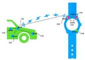
도 8 및 도 9를 참조하면, 일 실시 예에 따른 사용자 인식 웨어러블 스마트키 시스템(10)은 차량에 배치되어 차량의 상태를 감지하는 제1 센서부(110)를 포함하고, 상기 감지한 상기 차량의 상태를 포함하는 제1 센서 데이터를 데이터 저장부(120)에 저장한다. 상기 데이터 저장부(120)에 저장한 제1 센서 데이터는 제1 통신부(130)를 통해 제2 통신부(220)에 전송되고, 상태 판단부(230)는 상기 제1 통신부(130)로부터 전송받은 상기 제1 센서 데이터를 이용하여 차량의 상태를 판단할 수 있다. 이때, 상기 제1 센서 데이터 및 상기 데이터 생성부에서 판단한 차량의 상태는 표시부(240)에 표시될 수 있다.8 and 9 , the user-recognized wearable smart
또한, 상기 상태 판단부(230)는 상기 제2 센서부(210)가 감지한 사용자의 상태를 포함하는 제2 센서 데이터를 이용하여 사용자의 상태를 판단할 수 있다, 이때, 상기 제2 센서 데이터 및 상기 상태 판단부(230)에서 판단한 사용자의 상태는 표시부(240)에 표시될 수 있다. 또한, 차량 제어신호 생성부(240)는 상기 판단한 차량의 상태 및 상기 사용자의 상태에 따라 차량을 제어하는 차량제어신호를 제2 통신부(220)를 통해 상기 차량으로 전송할 수 있다.In addition, the
다른 예로, 제1 센서부(110)가 감지한 상기 차량의 상태를 포함하는 제1센터 데이터와 제2 센서부(210)가 감지한 상기 사용자의 상태를 포함하는 제2 센서 데이터를 사용자 단말기에서 수신 받아 처리하고 사용자가 운전 중 운전이 적합하지 않은 상태라면 사용자 단말기에서 구호처로 구조 요청 전화를 발신하는 예도 가능하다.As another example, the first center data including the state of the vehicle detected by the
따라서, 본 발명의 사상은 상기 설명된 실시예에 국한되어 정해져서는 아니되며, 후술하는 청구범위뿐만 아니라 이 청구범위와 균등하게 또는 등가적으로 변형된 모든 것들은 본 발명의 사상의 범주에 속한다고 할 것이다.Therefore, the spirit of the present invention should not be limited to the above-described embodiments, and not only the claims described below, but also all modifications equivalently or equivalently to the claims described below belong to the scope of the spirit of the present invention. will be.
10: 사용자 인식 웨어러블 스마트키 시스템
100: 차량
110: 제1 센서부
120: 데이터 저장부
130: 제1 통신부
140: 차량제어모듈
200: 스마트키
210: 제2 센서부
220: 제2 통신부
230: 상태 판단부
240: 차량 제어신호 생성부
250: 표시부10: User-aware wearable smart key system
100: vehicle
110: first sensor unit
120: data storage unit
130: first communication unit
140: vehicle control module
200: smart key
210: second sensor unit
220: second communication unit
230: state determination unit
240: vehicle control signal generator
250: display
Claims (12)
Translated fromKorean상기 차량과 연동되는 스마트키에 배치되고, 사용자의 상태를 감지하는 제2 센서부;
상기 차량에 배치되며, 상기 제1 센서부가 감지한 제1 센서 데이터를 저장하는 데이터 저장부;
상기 차량에 배치되며, 상기 데이터 저장부에 저장된 제1 센서 데이터를 상기 스마트키에 전송하는 제1 통신부;
상기 스마트키에 배치되어 상기 제1 센서데이터를 이용하여 상기 차량의 도난시도 여부를 포함하는 정상 작동 여부 및 충전장치의 이상 여부를 판단하고, 상기 제2 센서부가 감지한 제2 센서 데이터를 이용하여 상기 사용자가 운전이 불가능한 상태인지 여부를 판단하고, 상태 데이터를 생성하는 상태 판단부;
상기 상태 판단부가 생성한 상태 데이터에 따라 상기 차량을 제어하는 차량제어신호를 생성하는 차량 제어신호 생성부;
상기 스마트키에 배치되고 상기 차량제어신호를 상기 차량으로 전송하는 제2 통신부;
상기 차량에 배치되고 상기 차량제어신호에 따라 차량을 제어하는 차량제어모듈; 및
상기 스마트키에 배치되고 상기 제1 센서 데이터, 상기 제2 센서 데이터 및 상기 상태 데이터를 표시하는 표시부를 포함하고,
상기 제1 센서부는,
상기 차량에 가해지는 충격을 감지하는 충격 센서;
상기 차량의 문의 개폐 및 문 손잡이에 가해지는 압력을 감지하는 도어 센서;
상기 차량의 주변 소음을 감지하는 음향센서;
상기 차량의 전장부품의 상태를 감지하는 부품감지 센서; 및
상기 차량의 배터리의 상태를 감지하는 배터리 센서를 포함하고,
상기 충격센서가 감지한 이벤트의 패턴에 따라 알림 신호를 전송하는 이벤트 알림부를 더 포함하고,
상기 이벤트 알림부는,
처음 이벤트가 감지되면 상기 스마트키에 알림을 전송하는 제1 알림부; 및
반복적인 이벤트가 가해지면 상기 스마트키에 알림을 전송하는 제2 알림부를 포함하고,
상기 음향센서가 작동하면서 상기 충격센서에 충격이 감지되는 경우 비정상 작동으로 인식하고,
상기 음향센서의 작동은 아래의 식에 의해 결정되고, 음향센서 작동 변수가 0보다 작은 값이면 음향센서가 작동하지 않고, 음향센서 작동 변수가 0보다 큰 값이면 음향센서가 작동하는 것을 특징으로 하는 사용자 인식 웨어러블 스마트키 시스템.

(여기서, Z는 음향센서 작동변수,

a first sensor unit disposed in a vehicle and configured to detect a state of the vehicle;
a second sensor unit disposed on a smart key interlocked with the vehicle and configured to detect a user's state;
a data storage unit disposed in the vehicle and configured to store first sensor data sensed by the first sensor unit;
a first communication unit disposed in the vehicle and transmitting first sensor data stored in the data storage unit to the smart key;
It is disposed on the smart key and uses the first sensor data to determine whether the vehicle is operating normally, including whether the vehicle is attempted theft, and whether the charging device is abnormal, and using the second sensor data detected by the second sensor unit a state determination unit that determines whether the user is in a state in which driving is impossible, and generates state data;
a vehicle control signal generator configured to generate a vehicle control signal for controlling the vehicle according to the state data generated by the state determination unit;
a second communication unit disposed on the smart key and transmitting the vehicle control signal to the vehicle;
a vehicle control module disposed in the vehicle and controlling the vehicle according to the vehicle control signal; and
and a display unit disposed on the smart key and displaying the first sensor data, the second sensor data, and the state data,
The first sensor unit,
an impact sensor for detecting an impact applied to the vehicle;
a door sensor for sensing the opening and closing of the door of the vehicle and the pressure applied to the door handle;
an acoustic sensor for detecting ambient noise of the vehicle;
a component detection sensor for detecting the state of the electric component of the vehicle; and
A battery sensor for detecting the state of the vehicle's battery,
Further comprising an event notification unit for transmitting a notification signal according to the pattern of the event detected by the shock sensor,
The event notification unit,
a first notification unit for transmitting a notification to the smart key when an event is first detected; and
and a second notification unit for transmitting a notification to the smart key when a repetitive event is applied,
When an impact is detected by the impact sensor while the sound sensor operates, it is recognized as an abnormal operation,
The operation of the acoustic sensor is determined by the following equation, and if the acoustic sensor operation variable is a value less than 0, the acoustic sensor does not operate, and if the acoustic sensor operation parameter is a value greater than 0, the acoustic sensor operates User-aware wearable smart key system.
(where Z is the acoustic sensor operating variable,
상기 충격센서가 측정한 충격의 값이 소정의 충격의 값보다 큰 경우 및 상기 충격 센서에 처음 충격이 감지된 후 일정 횟수 이상 충격이 반복되어 감지되는 경우 비정상 작동으로 인식하고,
상기 충격 센서는 소정의 시간 주기로 상기 차량에 가해지는 충격을 감지하고, 소정의 충격의 값보다 큰 값으로 감지되는 경우 상기 제1 알림부가 상기 스마트키에 알림을 전송하고, 상기 제1 알림부가 알림을 전송하는 횟수가 소정의 횟수 이상인 경우 상기 제2 알림부가 상기 스마트키에 알림을 전송하는 것을 특징으로 하는 사용자 인식 웨어러블 스마트키 시스템.
The method of claim 1, wherein the state determination unit
When the value of the shock measured by the shock sensor is greater than the value of the predetermined shock, and when the shock is repeatedly detected more than a certain number of times after the first shock is sensed by the shock sensor, it is recognized as an abnormal operation,
The impact sensor detects an impact applied to the vehicle at a predetermined time period, and when a value greater than a predetermined impact value is detected, the first notification unit sends a notification to the smart key, and the first notification unit notifies A user-recognized wearable smart key system, characterized in that the second notification unit transmits a notification to the smart key when the number of times to transmit is greater than or equal to a predetermined number of times.
상기 충전장치의 이상 여부는 아래의 식에 의해 결정되고, 차량의 전력 상태 변수의 값이 1이면 충전 장치에 이상이 없는 것으로 판단하고, 차량의 전력 상태 변수의 값이 0이면 충전 장치에 이상이 있는 것으로 판단하는 것을 특징으로 하는 사용자 인식 웨어러블 스마트키 시스템.

(여기서,


According to claim 1,
Whether the charging device is abnormal is determined by the following equation, and if the value of the vehicle power state variable is 1, it is determined that there is no abnormality in the charging device, and if the value of the vehicle power state variable is 0, there is an abnormality in the charging device User-aware wearable smart key system, characterized in that it is determined that there is.
(here,
상기 사용자의 심전도 신호를 측정하기 위한 심전도 센서;
상기 사용자의 움직임의 변화를 측정하기 위한 관성센서;
상기 사용자의 움직임에 따른 가속도 측정을 위한 3축 가속도 센서; 및
상기 사용자의 체온, 혈압 등을 측정하기 위한 광센서를 포함하고,
상기 사용자가 상기 차량에 접근하는 경우 상기 제2 센서부가 상기 사용자의 상태를 측정하고, 상기 사용자가 운전 중일 경우 소정의 시간 간격으로 상기 사용자의 상태를 측정하는 것을 특징으로 하는 사용자 인식 웨어러블 스마트키 시스템.
According to claim 1, wherein the second sensor unit,
an electrocardiogram sensor for measuring the user's electrocardiogram signal;
an inertial sensor for measuring a change in the user's movement;
a 3-axis acceleration sensor for measuring acceleration according to the user's movement; and
and an optical sensor for measuring the user's body temperature, blood pressure, etc.;
When the user approaches the vehicle, the second sensor unit measures the user's state, and when the user is driving, measures the user's state at predetermined time intervals. .
상기 제2 센서부의 각 센서들의 초기 설정 값 및 변화율을 아래의 식에 의해 정의되는 것을 특징으로 하는 사용자 인식 웨어러블 스마트키 시스템.


(여기서,


8. The method of claim 7,
The user-recognized wearable smart key system, characterized in that the initial set value and change rate of each sensor of the second sensor unit is defined by the following equation.
(here,
상기 제2 센서부의 각 센서들의 측정 값으로 판단한 사용자의 상태 값은 아래의 식에 의해 정의되는 것을 특징으로 하는 사용자 인식 웨어러블 스마트키 시스템.


(여기서,


9. The method of claim 8,
The user's state value determined by the measurement values of the respective sensors of the second sensor unit is a user-recognized wearable smart key system, characterized in that defined by the following equation.
(here,
상기 사용자의 현재 상태는 아래의 식으로 정의되고, 사용자 현재 상태 값이 0이면 정상이고, 1이면 비정상으로 판단하는 것을 특징으로 하는 사용자 인식 웨어러블 스마트키 시스템.

(여기서, S는 사용자의 현재 상태 값이고,


10. The method of claim 9,
The user's current state is defined by the following equation, and if the user's current state value is 0, it is normal, and if it is 1, it is determined as abnormal.
(where S is the user's current state value,
상기


상기


상기


11. The method of claim 10, wherein the vehicle control signal generator,
remind
remind
remind
상기 제1 센서 데이터 및 상기 제2 센서 데이터를 수신 받는 사용자 단말기를 더 포함하는 사용자 인식 웨어러블 스마트키 시스템.
According to claim 1,
A user-recognized wearable smart key system further comprising a user terminal receiving the first sensor data and the second sensor data.
Priority Applications (3)
| Application Number | Priority Date | Filing Date | Title |
|---|---|---|---|
| KR1020210081364AKR102301508B1 (en) | 2021-06-23 | 2021-06-23 | Wearable smart key system for user recognition |
| CN202280035025.8ACN117355450A (en) | 2021-06-23 | 2022-06-22 | User identification wearable intelligent key system |
| PCT/KR2022/008837WO2022270891A1 (en) | 2021-06-23 | 2022-06-22 | User-recognizable wearable smart key system |
Applications Claiming Priority (1)
| Application Number | Priority Date | Filing Date | Title |
|---|---|---|---|
| KR1020210081364AKR102301508B1 (en) | 2021-06-23 | 2021-06-23 | Wearable smart key system for user recognition |
Publications (1)
| Publication Number | Publication Date |
|---|---|
| KR102301508B1true KR102301508B1 (en) | 2021-09-14 |
Family
ID=77774340
Family Applications (1)
| Application Number | Title | Priority Date | Filing Date |
|---|---|---|---|
| KR1020210081364AActiveKR102301508B1 (en) | 2021-06-23 | 2021-06-23 | Wearable smart key system for user recognition |
Country Status (3)
| Country | Link |
|---|---|
| KR (1) | KR102301508B1 (en) |
| CN (1) | CN117355450A (en) |
| WO (1) | WO2022270891A1 (en) |
Cited By (1)
| Publication number | Priority date | Publication date | Assignee | Title |
|---|---|---|---|---|
| WO2022270891A1 (en)* | 2021-06-23 | 2022-12-29 | ㈜에스엔디글로벌 | User-recognizable wearable smart key system |
Citations (6)
| Publication number | Priority date | Publication date | Assignee | Title |
|---|---|---|---|---|
| KR101427759B1 (en) | 2012-12-20 | 2014-08-07 | 현대오트론 주식회사 | Method for controlling terminal of vehicle interworking smart-key and contol apparatus thereof |
| KR20170074102A (en)* | 2015-12-21 | 2017-06-29 | 엘지전자 주식회사 | Smart key for vehicle and method for controlling the same |
| KR20190020908A (en)* | 2017-08-22 | 2019-03-05 | 현대자동차주식회사 | System and method for vehicle control |
| KR20190041481A (en)* | 2016-08-30 | 2019-04-22 | 엔쥬브 에토니 | Vehicle Security System |
| KR20190090367A (en)* | 2019-07-11 | 2019-08-01 | 엘지전자 주식회사 | Method and apparatus for detecting status of vehicle occupant |
| JP2019199178A (en)* | 2018-05-16 | 2019-11-21 | 社会医療法人蘇西厚生会 まつなみリサーチパーク | Safe driving support system |
Family Cites Families (1)
| Publication number | Priority date | Publication date | Assignee | Title |
|---|---|---|---|---|
| KR102301508B1 (en)* | 2021-06-23 | 2021-09-14 | 백우민 | Wearable smart key system for user recognition |
- 2021
- 2021-06-23KRKR1020210081364Apatent/KR102301508B1/enactiveActive
- 2022
- 2022-06-22CNCN202280035025.8Apatent/CN117355450A/enactivePending
- 2022-06-22WOPCT/KR2022/008837patent/WO2022270891A1/ennot_activeCeased
Patent Citations (6)
| Publication number | Priority date | Publication date | Assignee | Title |
|---|---|---|---|---|
| KR101427759B1 (en) | 2012-12-20 | 2014-08-07 | 현대오트론 주식회사 | Method for controlling terminal of vehicle interworking smart-key and contol apparatus thereof |
| KR20170074102A (en)* | 2015-12-21 | 2017-06-29 | 엘지전자 주식회사 | Smart key for vehicle and method for controlling the same |
| KR20190041481A (en)* | 2016-08-30 | 2019-04-22 | 엔쥬브 에토니 | Vehicle Security System |
| KR20190020908A (en)* | 2017-08-22 | 2019-03-05 | 현대자동차주식회사 | System and method for vehicle control |
| JP2019199178A (en)* | 2018-05-16 | 2019-11-21 | 社会医療法人蘇西厚生会 まつなみリサーチパーク | Safe driving support system |
| KR20190090367A (en)* | 2019-07-11 | 2019-08-01 | 엘지전자 주식회사 | Method and apparatus for detecting status of vehicle occupant |
Cited By (1)
| Publication number | Priority date | Publication date | Assignee | Title |
|---|---|---|---|---|
| WO2022270891A1 (en)* | 2021-06-23 | 2022-12-29 | ㈜에스엔디글로벌 | User-recognizable wearable smart key system |
Also Published As
| Publication number | Publication date |
|---|---|
| WO2022270891A1 (en) | 2022-12-29 |
| CN117355450A (en) | 2024-01-05 |
Similar Documents
| Publication | Publication Date | Title |
|---|---|---|
| JP2006341062A (en) | Emergency sensor | |
| JP2005034520A (en) | Physical condition monitoring system | |
| KR101416528B1 (en) | Wireless smart system for vehicle safety monitoring and accident prevention | |
| US20190228633A1 (en) | Fall Warning For A User | |
| CN107406081A (en) | Use the driver of the startup improved response time | |
| KR102301508B1 (en) | Wearable smart key system for user recognition | |
| KR101612507B1 (en) | Dangerous situation management system by self-protection ring | |
| KR101988426B1 (en) | Wrist type electricshock apparatus for preventing sleepiness | |
| JP2010108368A (en) | Radio terminal | |
| US20210099849A1 (en) | Emergency system for a vehicle | |
| KR20190114490A (en) | Wearable device for a vehicle and operating method thereof | |
| EP3756176A1 (en) | A wearable alarm device and a method of use thereof | |
| KR101808351B1 (en) | Method for detecting and transmitting emergency situations using smart device that control danger signal transmission using the physiological signal and plural password | |
| KR20190036822A (en) | Driver's Health Scanning System and Alarming Method Using It | |
| KR100925219B1 (en) | Vehicle safety accident prevention system and method | |
| KR102417890B1 (en) | Apparatus and method for monitoring status of driver | |
| CN108564775A (en) | Alarm method and system of distress call device and electronic equipment | |
| KR102099373B1 (en) | Health management system and method using smart watch type digital walkie-talkie | |
| US9129507B2 (en) | Portable electrical apparatus and method for detecting state of the same | |
| JP2014223849A (en) | Forgotten-charging notification system | |
| KR20190009008A (en) | Safety accident detection apparatus in vehicle and monitoring system comprising the same | |
| KR20170101434A (en) | Management system and method for elderly people living alone | |
| KR20070036952A (en) | Drowsiness prevention device and method | |
| KR102577039B1 (en) | Smart elevator door system with fall arrest | |
| KR100403177B1 (en) | A weight detection and alarm system used to a crane of hook and method for controlling as the same |
Legal Events
| Date | Code | Title | Description |
|---|---|---|---|
| PA0109 | Patent application | St.27 status event code:A-0-1-A10-A12-nap-PA0109 | |
| PA0201 | Request for examination | St.27 status event code:A-1-2-D10-D11-exm-PA0201 | |
| PA0302 | Request for accelerated examination | St.27 status event code:A-1-2-D10-D17-exm-PA0302 St.27 status event code:A-1-2-D10-D16-exm-PA0302 | |
| D13-X000 | Search requested | St.27 status event code:A-1-2-D10-D13-srh-X000 | |
| D14-X000 | Search report completed | St.27 status event code:A-1-2-D10-D14-srh-X000 | |
| E902 | Notification of reason for refusal | ||
| PE0902 | Notice of grounds for rejection | St.27 status event code:A-1-2-D10-D21-exm-PE0902 | |
| E13-X000 | Pre-grant limitation requested | St.27 status event code:A-2-3-E10-E13-lim-X000 | |
| P11-X000 | Amendment of application requested | St.27 status event code:A-2-2-P10-P11-nap-X000 | |
| P13-X000 | Application amended | St.27 status event code:A-2-2-P10-P13-nap-X000 | |
| E701 | Decision to grant or registration of patent right | ||
| PE0701 | Decision of registration | St.27 status event code:A-1-2-D10-D22-exm-PE0701 | |
| GRNT | Written decision to grant | ||
| PR0701 | Registration of establishment | St.27 status event code:A-2-4-F10-F11-exm-PR0701 | |
| PR1002 | Payment of registration fee | St.27 status event code:A-2-2-U10-U11-oth-PR1002 Fee payment year number:1 | |
| PG1601 | Publication of registration | St.27 status event code:A-4-4-Q10-Q13-nap-PG1601 | |
| PN2301 | Change of applicant | St.27 status event code:A-5-5-R10-R11-asn-PN2301 | |
| PN2301 | Change of applicant | St.27 status event code:A-5-5-R10-R14-asn-PN2301 | |
| P14-X000 | Amendment of ip right document requested | St.27 status event code:A-5-5-P10-P14-nap-X000 | |
| P16-X000 | Ip right document amended | St.27 status event code:A-5-5-P10-P16-nap-X000 | |
| Q16-X000 | A copy of ip right certificate issued | St.27 status event code:A-4-4-Q10-Q16-nap-X000 | |
| R18-X000 | Changes to party contact information recorded | St.27 status event code:A-5-5-R10-R18-oth-X000 | |
| PR1001 | Payment of annual fee | St.27 status event code:A-4-4-U10-U11-oth-PR1001 Fee payment year number:4 | |
| R18-X000 | Changes to party contact information recorded | St.27 status event code:A-5-5-R10-R18-oth-X000 |