KR102301500B1 - Display device - Google Patents
Display deviceDownload PDFInfo
- Publication number
- KR102301500B1 KR102301500B1KR1020150010841AKR20150010841AKR102301500B1KR 102301500 B1KR102301500 B1KR 102301500B1KR 1020150010841 AKR1020150010841 AKR 1020150010841AKR 20150010841 AKR20150010841 AKR 20150010841AKR 102301500 B1KR102301500 B1KR 102301500B1
- Authority
- KR
- South Korea
- Prior art keywords
- body part
- body portion
- support plate
- support
- display panel
- Prior art date
- Legal status (The legal status is an assumption and is not a legal conclusion. Google has not performed a legal analysis and makes no representation as to the accuracy of the status listed.)
- Active
Links
Images


Classifications
- G—PHYSICS
- G09—EDUCATION; CRYPTOGRAPHY; DISPLAY; ADVERTISING; SEALS
- G09F—DISPLAYING; ADVERTISING; SIGNS; LABELS OR NAME-PLATES; SEALS
- G09F9/00—Indicating arrangements for variable information in which the information is built-up on a support by selection or combination of individual elements
- G09F9/30—Indicating arrangements for variable information in which the information is built-up on a support by selection or combination of individual elements in which the desired character or characters are formed by combining individual elements
- G09F9/301—Indicating arrangements for variable information in which the information is built-up on a support by selection or combination of individual elements in which the desired character or characters are formed by combining individual elements flexible foldable or roll-able electronic displays, e.g. thin LCD, OLED
- G—PHYSICS
- G06—COMPUTING OR CALCULATING; COUNTING
- G06F—ELECTRIC DIGITAL DATA PROCESSING
- G06F1/00—Details not covered by groups G06F3/00 - G06F13/00 and G06F21/00
- G06F1/16—Constructional details or arrangements
- G06F1/1613—Constructional details or arrangements for portable computers
- G06F1/1633—Constructional details or arrangements of portable computers not specific to the type of enclosures covered by groups G06F1/1615 - G06F1/1626
- G06F1/1637—Details related to the display arrangement, including those related to the mounting of the display in the housing
- G06F1/1652—Details related to the display arrangement, including those related to the mounting of the display in the housing the display being flexible, e.g. mimicking a sheet of paper, or rollable
- G—PHYSICS
- G06—COMPUTING OR CALCULATING; COUNTING
- G06F—ELECTRIC DIGITAL DATA PROCESSING
- G06F1/00—Details not covered by groups G06F3/00 - G06F13/00 and G06F21/00
- G06F1/16—Constructional details or arrangements
- G06F1/1613—Constructional details or arrangements for portable computers
- G06F1/1615—Constructional details or arrangements for portable computers with several enclosures having relative motions, each enclosure supporting at least one I/O or computing function
- G06F1/1624—Constructional details or arrangements for portable computers with several enclosures having relative motions, each enclosure supporting at least one I/O or computing function with sliding enclosures, e.g. sliding keyboard or display
- G—PHYSICS
- G06—COMPUTING OR CALCULATING; COUNTING
- G06F—ELECTRIC DIGITAL DATA PROCESSING
- G06F1/00—Details not covered by groups G06F3/00 - G06F13/00 and G06F21/00
- G06F1/16—Constructional details or arrangements
- G06F1/1613—Constructional details or arrangements for portable computers
- G06F1/1626—Constructional details or arrangements for portable computers with a single-body enclosure integrating a flat display, e.g. Personal Digital Assistants [PDAs]
- G—PHYSICS
- G09—EDUCATION; CRYPTOGRAPHY; DISPLAY; ADVERTISING; SEALS
- G09F—DISPLAYING; ADVERTISING; SIGNS; LABELS OR NAME-PLATES; SEALS
- G09F9/00—Indicating arrangements for variable information in which the information is built-up on a support by selection or combination of individual elements
- G09F9/30—Indicating arrangements for variable information in which the information is built-up on a support by selection or combination of individual elements in which the desired character or characters are formed by combining individual elements
- G09F9/33—Indicating arrangements for variable information in which the information is built-up on a support by selection or combination of individual elements in which the desired character or characters are formed by combining individual elements being semiconductor devices, e.g. diodes
- H—ELECTRICITY
- H10—SEMICONDUCTOR DEVICES; ELECTRIC SOLID-STATE DEVICES NOT OTHERWISE PROVIDED FOR
- H10K—ORGANIC ELECTRIC SOLID-STATE DEVICES
- H10K77/00—Constructional details of devices covered by this subclass and not covered by groups H10K10/80, H10K30/80, H10K50/80 or H10K59/80
- H10K77/10—Substrates, e.g. flexible substrates
- H10K77/111—Flexible substrates
Landscapes
- Engineering & Computer Science (AREA)
- Theoretical Computer Science (AREA)
- Physics & Mathematics (AREA)
- General Physics & Mathematics (AREA)
- Computer Hardware Design (AREA)
- Human Computer Interaction (AREA)
- General Engineering & Computer Science (AREA)
- Mathematical Physics (AREA)
- Devices For Indicating Variable Information By Combining Individual Elements (AREA)
Abstract
Translated fromKoreanDescription
Translated fromKorean본 발명은 표시 장치에 관한 것으로서, 보다 상세하게는 플렉서블(flexible) 표시 패널을 포함하는 표시 장치에 관한 것이다.The present invention relates to a display device, and more particularly, to a display device including a flexible display panel.
표시 장치는 이미지 또는 를 표시하는 장치로서, 최근 플렉서블 표시 장치(flexible display device)가 주목 받고 있다.A display device is a device that displays an image or , and a flexible display device has recently been attracting attention.
종래의 플렉서블 표시 장치는 이미지(image)를 표시하는 플렉서블 표시 패널을 포함하는 장치로서, 플렉서블 표시 패널이 플렉서블함에 따라 플렉서블 표시 패널을 접거나 롤(roll)에 말아 전체적인 플렉서블 표시 장치의 크기를 줄여 휴대할 수 있었다.A conventional flexible display device includes a flexible display panel that displays an image. As the flexible display panel is flexible, the flexible display panel is folded or rolled into a roll to reduce the overall size of the flexible display device for portability. Could.
그러나 접는 플렉서블 표시 패널의 경우, 반복적으로 접히는 부분에 결합이 발생할 가능성이 매우 크며 결함은 플렉서블 표시 패널의 중앙에 발생하므로 사용자에게 불편감을 주는 문제가 있다. 또한 롤에 말아서 사용하는 플렉서블 표시 장치의 경우 표시 장치를 평면으로 지지하지 못할 뿐만 아니라 사용자가 이를 잡고 있어야 하므로 장시간 안정적으로 사용하기에 불편한 문제가 있다.
However, in the case of a foldable flexible display panel, there is a very high possibility that coupling occurs in the repeatedly folded portion, and a defect occurs in the center of the flexible display panel, which causes inconvenience to the user. In addition, in the case of a flexible display device rolled on a roll, it is not possible to support the display device in a flat surface, and a user must hold the display device, so it is inconvenient to use it stably for a long time.
본 발명의 일 실시예는, 견고한 구조를 가지면서 화면을 확장시킬 수 있는 표시 장치를 제공하고자 한다.SUMMARY One embodiment of the present invention is to provide a display device capable of expanding a screen while having a solid structure.
상술한 기술적 과제를 달성하기 위한 본 발명의 일 측면은 내부 공간을 갖고 일측면에 개구가 형성된 제1 몸체부, 내부 공간을 갖고, 상기 개구와 마주하는 제2 개구가 일측면에 형성된 제2 몸체부, 화상을 표시하며 상기 제1 몸체부와 상기 제2 몸체부의 간격 변화에 따라 표시 면적이 변화하는 플렉서블 표시 패널, 및 상기 제1 몸체부와 제2 몸체부를 연결하며, 회전 가능하도록 결합된 복수개의 커넥팅 암을 갖는 암 어셈블리를 포함하는 표시 장치를 제공한다.One aspect of the present invention for achieving the above-described technical problem is a first body portion having an inner space and an opening formed on one side thereof, a second body having an inner space and a second opening facing the opening formed on one side thereof a flexible display panel for displaying a portion, an image and having a display area changed according to a change in a distance between the first body portion and the second body portion, and a plurality of rotatably coupled portions connecting the first body portion and the second body portion A display device including an arm assembly having two connecting arms is provided.
여기서, 상기 암 어셈블리는 상기 제1 몸체부와 상기 제2 몸체부에 각각 고정된 지지 축들, 상기 지지 축들에 각각 회전 가능하도록 결합된 커넥팅 암들, 및 상기 커넥팅 암들을 연결하며 상기 커넥팅 암들에 대하여 회전 가능하게 설치된 가변 축을 포함할 수 있다.Here, the arm assembly includes supporting shafts fixed to the first body part and the second body part, respectively, connecting arms rotatably coupled to the supporting shafts, respectively, and connecting the connecting arms and rotating with respect to the connecting arms. It may include a variable shaft possibly installed.
또한, 상기 제1 몸체부에는 이격된 제2개의 제1 지지 축이 설치되고 상기 제2 몸체부에는 이격된 2개의 제2 지지 축이 설치되며 상기 제1 지지 축들과 상기 제2 지지 축들에는 각각 커넥팅 암들이 회전 가능하도록 설치되고, 상기 가변 축은 상기 제1 몸체부에 연결된 커넥팅 암과 상기 제2 몸체부에 연결된 커넥팅 암을 회전 가능하도록 연결할 수 있다.In addition, two first support shafts spaced apart from each other are installed on the first body part, and two second support shafts spaced apart from the second body part are installed on the first support shafts and the second support shafts, respectively. The connecting arms are rotatably installed, and the variable shaft may rotatably connect the connecting arm connected to the first body part and the connecting arm connected to the second body part.
또한, 상기 제1 몸체부에는 제1 커버가 결합되고 상기 커버에는 상기 플렉서블 표시 패널이 관통하는 홀이 형성될 수 있으며, 상기 제1 몸체부에는 슬라이딩 가능하게 결합된 제1 지지판이 설치될 수 있다.In addition, a first cover may be coupled to the first body portion, a hole through which the flexible display panel passes may be formed in the cover, and a first support plate slidably coupled to the first body portion may be installed. .
또한, 상기 제1 몸체부의 내측 벽면에는 상기 제1 지지판이 삽입되는 안착 홈이 형성될 수 있으며, 상기 제1 지지판의 측면에는 지지 핀이 돌출 형성되고 상기 안착 홈에는 상기 제1 지지판의 이동 방향으로 이어져 형성되며, 상기 지지 핀이 삽입되는 가이드 홈이 형성될 수 있다.In addition, a seating groove into which the first support plate is inserted may be formed on the inner wall surface of the first body part, a support pin is protruded from a side surface of the first support plate, and a support pin is formed in the seating groove in the moving direction of the first support plate It is formed in series, and a guide groove into which the support pin is inserted may be formed.
또한, 상기 제2 몸체부에는 슬라이딩 가능하게 결합된 제2 지지판이 설치되고 상기 제1 지지판과 상기 제2 지지판은 측단이 서로 마주하도록 배치될 수 있으며, 상기 제1 지지판에는 상기 제2 지지판을 향하여 돌출된 연결 돌기가 형성되고 상기 제2 지지판에는 상기 연결 돌기가 삽입되는 연결 홈이 형성될 수 있다.In addition, a second support plate slidably coupled to the second body portion may be installed, and the side ends of the first support plate and the second support plate may be disposed to face each other, and the first support plate has the first support plate toward the second support plate. A protruding connection protrusion may be formed, and a connection groove into which the connection projection is inserted may be formed in the second support plate.
또한, 상기 제1 몸체부에는 상기 제2 몸체부를 향하여 돌출된 걸림 턱이 형성되고, 상기 제2 몸체부에서 제1 몸체부와 마주하는 측면에는 상기 걸림 턱이 삽입되어 걸려지는 락킹 홈이 형성될 수 있다.In addition, the first body portion is formed with a locking jaw protruding toward the second body portion, and a locking groove into which the locking jaw is inserted and hooked is formed on a side surface of the second body portion facing the first body portion. can
또한, 상기 제1 몸체부에는 상기 플렉서블 표시 패널의 길이방향 일측 단부가 감기는 제1 롤러가 설치되고, 상기 제2 몸체부에는 상기 플렉서블 표시 패널의 길이방향 타측 단부가 감기는 제2 롤러가 설치될 수 있다.In addition, a first roller around one end of the flexible display panel in the longitudinal direction is installed on the first body, and a second roller around the other end of the flexible display panel in the longitudinal direction is installed on the second body. can be
또한, 상기 플렉서블 표시 패널의 길이방향 일측 단부에는 제1 지지 막대가 설치되고, 상기 플렉서블 표시 패널의 길이방향 타측 단부에는 제2 지지 막대가 설치되며 상기 플렉서블 표시 패널은 상기 제1 몸체부와 상기 제2 몸체부를 감싸도록 설치되고 상기 제1 지지 막대와 상기 제2 지지 막대는 상기 제1 몸체부와 상기 제2 몸체부의 아래에 배치될 수 있다. 또한, 상기 제1 지지 막대와 상기 제2 지지 막대는 탄성체를 매개로 연결될 수 있다.In addition, a first support bar is installed at one end of the flexible display panel in the longitudinal direction, a second support bar is installed at the other end of the flexible display panel in the longitudinal direction, and the flexible display panel includes the first body and the first body. It is installed to surround the second body part, and the first support bar and the second support bar may be disposed under the first body part and the second body part. In addition, the first support bar and the second support bar may be connected via an elastic body.
상술한 본 발명의 과제 해결 수단의 일부 실시예 중 하나에 의하면, 플렉서블 표시 패널의 플렉서블 특성에 최적화된 이미지를 표시하는 표시 장치가 제공된다.According to one of some embodiments of the above-described means for solving the problems of the present invention, a display device for displaying an image optimized for the flexible characteristics of the flexible display panel is provided.
도 1은 본 발명의 제1 실시예에 따른 표시 장치를 나타낸 사시도이다.
도 2는 본 발명의 제1 실시예에 따른 표시 장치가 확장된 상태를 나타낸 사시도이다.
도 3은 본 발명의 제1 실시예에 따른 표시 장치를 나타낸 분해 사시도이다.
도 4는 본 발명의 제1 실시예에 따른 표시 장치를 잘라본 횡단면도이다.
도 5는 본 발명의 제1 실시예에 따른 표시 장치의 몸체부들이 결합된 상태를 나타낸 부분 단면도이다.
도 6은 본 발명의 제1 실시예에 따른 표시 장치의 지지판들이 결합된 상태를 나타낸 부분 단면도이다.
도 7은 본 발명의 제2 실시예에 따른 표시 장치를 잘라본 횡단면도이다.
도 8은 본 발명의 제2 실시예에 따른 표지 장치의 몸체부들이 이격된 상태를 도시한 횡단면도이다.
도 9는 본 발명의 제3 실시예에 따른 표시 장치를 나타낸 사시도이다.
도 10은 본 발명의 제3 실시예에 따른 표시 장치를 나타낸 종단면도이다.
도 11은 본 발명의 제3 실시예에 따른 표시 장치가 확장된 상태를 나타낸 종단면도이다.1 is a perspective view illustrating a display device according to a first exemplary embodiment of the present invention.
2 is a perspective view illustrating an expanded state of the display device according to the first exemplary embodiment of the present invention.
3 is an exploded perspective view illustrating a display device according to a first exemplary embodiment of the present invention.
4 is a cross-sectional view of the display device according to the first exemplary embodiment of the present invention.
5 is a partial cross-sectional view illustrating a state in which body parts of the display device according to the first exemplary embodiment are coupled to each other.
6 is a partial cross-sectional view illustrating a state in which support plates of the display device according to the first exemplary embodiment are coupled.
7 is a cross-sectional view of a display device according to a second exemplary embodiment of the present invention.
8 is a cross-sectional view illustrating a state in which the body parts of the labeling device according to the second embodiment of the present invention are spaced apart.
9 is a perspective view illustrating a display device according to a third exemplary embodiment of the present invention.
10 is a longitudinal cross-sectional view illustrating a display device according to a third exemplary embodiment of the present invention.
11 is a longitudinal cross-sectional view illustrating an expanded state of a display device according to a third exemplary embodiment of the present invention.
이하, 첨부한 도면을 참고로 하여 본 발명의 여러 실시예들에 대하여 본 발명이 속하는 기술 분야에서 통상의 지식을 가진 자가 용이하게 실시할 수 있도록 상세히 설명한다. 본 발명은 여러 가지 상이한 형태로 구현될 수 있으며 여기에서 설명하는 실시예들에 한정되지 않는다.Hereinafter, with reference to the accompanying drawings, various embodiments of the present invention will be described in detail so that those of ordinary skill in the art can easily implement them. The present invention may be embodied in many different forms and is not limited to the embodiments described herein.
본 발명을 명확하게 설명하기 위해서 설명과 관계없는 부분은 생략하였으며, 명세서 전체를 통하여 동일 또는 유사한 구성요소에 대해서는 동일한 참조 부호를 붙이도록 한다.In order to clearly explain the present invention, parts irrelevant to the description are omitted, and the same reference numerals are given to the same or similar elements throughout the specification.
또한, 도면에서 나타난 각 구성의 크기 및 두께는 설명의 편의를 위해 임의로 나타내었으므로, 본 발명이 반드시 도시된 바에 한정되지 않는다.In addition, since the size and thickness of each component shown in the drawings are arbitrarily indicated for convenience of description, the present invention is not necessarily limited to the illustrated bar.
도면에서 여러 층 및 영역을 명확하게 표현하기 위하여 두께를 확대하여 나타내었다. 그리고 도면에서, 설명의 편의를 위해, 일부 층 및 영역의 두께를 과장되게 나타내었다. 일 부분이 다른 부분 "상에" 있다고 할 때, 이는 다른 부분 "바로 상에" 있는 경우뿐 아니라 그 중간에 또 다른 부분이 있는 경우도 포함한다.In order to clearly express various layers and regions in the drawings, the thicknesses are enlarged. And in the drawings, for convenience of description, the thickness of some layers and regions are exaggerated. When a part is said to be "on" another part, this includes not only the case where the other part is "immediately on" but also the case where there is another part in between.
또한, 명세서 전체에서, 어떤 부분이 어떤 구성요소를 "포함" 한다고 할 때, 이는 특별히 반대되는 기재가 없는 한 다른 구성요소를 제외하는 것이 아니라 다른 구성요소를 더 포함할 수 있는 것을 의미한다. 또한, 명세서 전체에서, "~상에"라 함은 대상 부분의 위 또는 아래에 위치함을 의미하는 것이며, 반드시 중력 방향을 기준으로 상 측에 위치하는 것을 의미하는 것은 아니다.In addition, throughout the specification, when a part "includes" a certain component, this means that other components may be further included, rather than excluding other components, unless otherwise stated. In addition, throughout the specification, "on" means to be located above or below the target portion, and does not necessarily mean to be located above the direction of gravity.
도 1은 본 발명의 제1 실시예에 따른 표시 장치를 나타낸 사시도이고, 도 2는 본 발명의 제1 실시예에 따른 표시 장치가 확장된 상태를 나타낸 사시도이다.1 is a perspective view illustrating a display device according to a first embodiment of the present invention, and FIG. 2 is a perspective view illustrating an expanded state of the display device according to the first embodiment of the present invention.
도 1 및 도 2를 참조하여 설명하면, 본 제1 실시예에 따른 표시 장치(101)는 플렉서블 표시 패널(23), 제1 몸체부(12), 제2 몸체부(13), 암 어셈블리(40), 제1 지지판(31), 및 제2 지지판(32)을 포함한다.1 and 2 , the
플렉서블 표시 패널(23)은 표시 장치에서 처리되는 이미지(image), 영상, 또는 문자를 표시한다. 일례로, 표시 장치가 휴대폰 등의 이동 단말기일 경우, 통화와 관련된 UI(User Interface) 또는 GUI(Graphic User Interface) 등의 이미지를 표시할 수 있다. 플렉서블 표시 패널(23)은 액정(liquid crystal) 또는 유기 발광 소자(organic light emitting diode) 등을 사이에 두고 상호 대향하는 플렉서블한 기판 또는 필름 등을 포함할 수 있다.The
플렉서블 표시 패널(23)은 플렉서블 표시 패널(23)을 통해 외부를 볼 수 있도록 투명형 또는 광투과형으로 구성될 수 있다. 플렉서블 표시 패널(23)의 전면에는 터치 필름, 터치 시트, 터치 패드 등의 형태를 가지고 터치(touch) 동작을 감지하는 터치 센서가 위치할 수 있다. The
플렉서블 표시 패널(23)은 플렉서블한 특성을 가지고 있으며, 제1 몸체부(12) 및 제2 몸체부(13)의 내부로 출입(出入)된다. 플렉서블 표시 패널(23)의 길이방향 일측 단부는 제1 몸체부(12)에 삽입된 제1 롤러(21)에 감겨지고, 플렉서블 표시 패널(23)의 길이방향 타측 단부는 제2 몸체부(13)에 삽입된 제2 롤러(22)에 감겨진다. 제1 롤러(21)와 제2 롤러(22)에는 플렉서블 표시 패널(23)에 장력을 인가하는 텐션 스프링이 설치될 수 있다. 제1 롤러(21)와 제2 롤러(22)는 제1 몸체부(12)와 제2 몸체부(13)의 간격에 따라 회전하며, 제1 롤러(21)와 제2 롤러(22)의 회전에 따라 플렉서블 표시 패널(23)에서 화상이 표시되는 표시 면적이 변화된다. The
제1 몸체부(12)는 내부 공간을 갖고 일측면에 개방된 개구(125)가 형성된다. 제1 몸체부(12)는 대략 직육면체 형상으로 이루어지며 제1 몸체부(12)의 상면에는 제1 커버(14)가 결합된다. 제1 커버(14)는 사각판 형상으로 이루어지며 제1 커버에는 플렉서블 표시 패널이 관통하는 홀(141)이 형성된다.The
제1 몸체부(12)에는 상기한 제1 롤러(21)가 회전 가능하도록 설치되어 있다.The
제1 몸체부(12)에는 제1 지지판(31)이 삽입 설치되는데, 제1 지지판(31)은 제1 몸체부(12)에 대하여 슬라이딩 가능하도록 설치된다. 제1 몸체부(12)의 내측 벽면에는 제1 지지판(31)이 삽입되는 안착 홈(121)이 형성되는 바, 안착 홈(121)은 제1 몸체부(12)의 마주하는 벽면의 내측에 형성되며, 개구(125)를 향하여 이어져 형성된다.A
안착 홈(121)에는 제1 지지판(31)에 형성된 지지 핀(312)이 삽입된 가이드 홈(123)이 형성된다. 가이드 홈(123)은 제1 지지판(31)의 이동방향으로 이어져 형성된다. 가이드 홈(123)은 일자로 이어져 형성될 수 있을 뿐만 아니라 개구(125)측으로 갈수록 위로 향하도록 이어져 형성될 수도 있다.A
제1 몸체부(12)에는 제2 몸체부(13)를 향하여 돌출된 걸림 턱(126)이 형성되고, 제2 몸체부(13)에서 제1 몸체부(12)와 마주하는 측면에는 걸림 턱(126)이 삽입되어 걸려지는 락킹 홈(136)이 형성된다. 걸림 턱(126)은 제1 몸체부(12)에서 제2 몸체부(13)를 향하는 면에 형성되며, 걸림 턱(126)과 락킹 홈(136)이 끼움 결합되면 제1 몸체부(12)와 제2 몸체부(13)가 맞닿은 상태를 안정적으로 유지할 수 있다. 한편, 제1 몸체부(12)에는 걸림 턱(126)과 락킹 홈(136)의 결합을 해제시키는 버턴이 설치될 수 있다.The
제1 지지판(31)은 개구(125)를 통해서 제1 몸체부(12) 내부로 출입 가능하도록 설치되며 제1 지지판(31)의 양쪽 측단은 안착 홈(121)에 지지된다. 또한 제1 지지판(31)의 양쪽 측면에는 가이드 홈(123)에 삽입되는 지지 핀(312)이 형성된다.The
도 1 및 도 5에 도시된 바와 같이 제1 지지판(31)에는 제2 몸체부(13)를 향하여 돌출된 연결 돌기(315)가 형성되고, 제2 지지판(32)에는 연결 돌기(315)가 삽입되는 연결 홈(323)이 형성된다. 제1 지지판(31)에는 제2 지지판(32)을 향하여 돌출된 지지대(313)가 형성되고, 연결 돌기(315)는 지지대(313) 상에서 상부로 돌출된다. 지지대(313)는 제1 지지판(31)의 측면에서 돌출 형성될 수 있다. 연결 홈(323)은 제2 지지판(32)의 하면에 형성된다.As shown in FIGS. 1 and 5 , a connecting
다만 본 발명이 이에 제한되는 것은 아니며 연결 돌기 제1 몸체부의 측면에서 직접 돌출되고 연결 홈은 제2 몸체부에서 제1 몸체부를 향하는 측면에 형성될 수 있다.However, the present invention is not limited thereto, and the connection protrusion may directly protrude from the side surface of the first body part, and the connection groove may be formed on the side surface facing the first body part from the second body part.
제2 몸체부(13)는 내부 공간을 갖고 일측면에 개방된 개구(135)가 형성된다. 제2 몸체부(13)에 형성된 개구는 제1 몸체부(12)에 형성된 개구(125)와 마주하도록 배치된다. 제2 몸체부(13)는 대략 직육면체 형상으로 이루어지며 제1 몸체부(12)의 상면에는 제2 커버(15)가 결합된다. 제2 커버(15)는 사각판 형상으로 이루어지며 제2 커버에는 플렉서블 표시 패널이 관통하는 홀(151)이 형성된다.The
제2 몸체부(13)에는 상기한 제2 롤러(22)가 회전 가능하도록 설치되어 있다.The
제2 몸체부(13)에는 제2 지지판(32)이 삽입 설치되는데, 제2 지지판(32)은 제2 몸체부(13)에 대하여 슬라이딩 가능하도록 설치된다. 제2 몸체부(13)에는 제2 지지판(32)이 삽입되는 안착 홈(131)이 형성되는 바, 안착 홈(131)은 제2 몸체부(13)의 마주하는 벽면의 내측에 형성되며, 개구(135)를 향하여 이어져 형성된다.A
안착 홈(131)에는 제2 지지판(32)에 형성된 지지 핀(322)이 삽입된 가이드 홈(133)이 형성된다. 가이드 홈(133)은 제2 지지판(32)의 이동방향으로 이어져 형성된다. 가이드 홈(133)은 일자로 이어져 형성될 수 있을 뿐만 아니라 개구(135)측으로 갈수록 위로 향하도록 이어져 형성될 수도 있다.A
제2 지지판(32)은 개구(135)를 통해서 제2 몸체부(13) 내부로 출입 가능하도록 설치되며 제2 지지판(32)의 양쪽 측단은 안착 홈(131)에 지지된다. 또한 제2 지지판(32)의 양쪽 측면에는 가이드 홈(133)에 삽입되는 지지 핀(322)이 형성된다.The
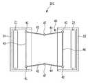
도 4는 본 발명의 제1 실시예에 따른 표시 장치를 잘라본 횡단면도이다.4 is a cross-sectional view of the display device according to the first exemplary embodiment of the present invention.
도 1 및 도 4에 도시된 바와 같이, 제1 몸체부(12) 및 제2 몸체부(13)에는 암 어셈블리(40)가 설치되는데, 암 어셈블리(40)는 제1 몸체부(12)와 제2 몸체부(13)에 각각 고정된 지지 축들(41, 42), 지지 축(41, 42)에 각각 회전 가능하도록 결합된 커넥팅 암들(43, 44), 및 커넥팅 암들(43, 44)을 연결하는 가변 축(47)을 포함한다.1 and 4 , an
제1 몸체부(12)에는 2개의 지지 축(41)이 제1 몸체부의 폭방향으로 이격 배치되며 지지 축들(41)에는 지지 축들(41)을 연결 고정하는 고정 암(45)이 설치된다. 지지 축들(41)에는 제2 몸체부(13)를 향하여 이어진 커넥팅 암(43)이 각각 회전 가능하도록 결합된다. 또한 제2 몸체부(13)에는 2개의 지지 축(42)이 제2 몸체부(13)의 폭방향으로 이격 배치되며 지지 축들(42)에는 지지 축들(42)을 연결 고정하는 고정 암(46)이 설치된다. 지지 축들(42)에는 제2 몸체부(13)를 향하여 이어진 커넥팅 암(44)이 각각 회전 가능하도록 결합된다.The
제1 몸체부(12)에 연결된 커넥팅 암(43)은 제2 몸체부(13)에 연결된 커넥팅 암(44)과 가변 축(47)을 매개로 회전 가능하도록 연결된다. 가변 축(47)은 제1 몸체부(12) 또는 제2 몸체부(13)에 고정되지 않으며 이동 가능하도록 설치된다.The connecting
본 제1 실시예에서는 지지 축(41, 42)이 2개의 커넥팅 암(43, 44)에 의하여 연결된 것으로 예시하고 있으나 본 발명이 이에 제한되는 것은 아니며 지지 축은 2개 이상의 커넥팅 암으로 연결될 수 있다.In the first embodiment, the
암 어셈블리(40)는 제1 몸체부(12)와 제2 몸체부(13)를 지지하며 제1 몸체부(12)와 제2 몸체부(13)의 이동에 따라 제1 몸체부(12)와 제2 몸체부(13)의 내부로 삽입되거나 이탈한다. 도 2에 도시된 바와 같이 제1 몸체부(12)와 제2 몸체부(13)가 맞닿아 있으면 커넥팅 암들(43, 44)이 접혀서 제1 몸체부(12)와 제2 몸체부(13) 내부로 삽입되며, 도 3에 도시된 바와 같이 제1 몸체부(12)와 제2 몸체부(13)가 이격되면 커넥팅 암들(43, 44)이 제1 몸체부(12)와 제2 몸체부(13)에서 이탈되어 펴진다.The
또한, 제1 몸체부(12)와 제2 몸체부(13)의 간격이 증가하면 제1 지지판(31)과 제2 지지판(32)이 각각 제1 몸체부(12)와 제2 몸체부(13)에서 이탈한다. 지지 핀들(312, 322)이 가이드 홈(123, 133)의 길이방향 단부에 맞닿으면 제1 지지판(31)과 제2 지지판(32)이 제1 몸체부(12)와 제2 몸체부(13)를 지지하여 제1 몸체부(12)와 제2 몸체부(13) 사이의 간격은 더 이상 증가하지 못한다.In addition, when the distance between the
상기한 바와 같이 본 제1 실시예에 따르면 제1 몸체부(12)와 제2 몸체부(13)가 암 어셈블리(40)에 의하여 지지되므로 서로에 대하여 용이하게 이동할 수 있다. 또한 제1 지지판(31)과 제2 지지판(32)이 설치되므로 펼쳐진 플렉서블 표시 패널(23)을 용이하게 지지할 수 있다.As described above, according to the first embodiment, since the
이하, 도 7 및 도 8을 참조하여 본 발명의 제2 실시예에 따른 표시 장치를 설명한다Hereinafter, a display device according to a second exemplary embodiment of the present invention will be described with reference to FIGS. 7 and 8 .
이하, 제1 실시예와 구별되는 특징적인 부분만 발췌하여 설명하며, 설명이 생략된 부분은 제1 실시예에 따른다. 그리고, 본 발명의 제2 실시예에서는 설명의 편의를 위하여 동일한 구성요소에 대하여는 본 발명의 제1 실시예와 동일한 참조번호를 사용하여 설명한다.Hereinafter, only characteristic parts distinguished from the first embodiment will be extracted and described, and the omitted parts will be according to the first embodiment. In addition, in the second embodiment of the present invention, the same reference numerals as in the first embodiment of the present invention are used for the same components for convenience of description.
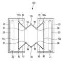
도 7은 본 발명의 제2 실시예에 따른 표시 장치를 잘라본 횡단면도이고, 도 8은 본 발명의 제2 실시예에 따른 표지 장치의 몸체부들이 이격된 상태를 도시한 횡단면도이다.7 is a cross-sectional view of a display device according to a second embodiment of the present invention, and FIG. 8 is a cross-sectional view illustrating a state in which body parts of the display device according to the second embodiment of the present invention are spaced apart.
도 7 및 도 8에 도시된 바와 같이, 본 발명의 제2 실시예에 따른 표시 장치(102)는 플렉서블 표시 패널, 제1 몸체부와 제2 몸체부, 암 어셈블리, 제1 지지판 및 제2 지지판을 포함한다.7 and 8 , the
제1 몸체부(12) 및 제2 몸체부(13)에는 암 어셈블리(90)가 설치되는데, 암 어셈블리(90)는 제1 몸체부(12)와 제2 몸체부(13)에 각각 고정된 지지 축들(91, 92), 지지 축(91, 92)에 각각 회전 가능하도록 결합된 커넥팅 암들(93, 94, 95, 96), 및 커넥팅 암들(93, 94, 95, 96)을 연결하는 가변 축(97, 98, 99)을 포함한다.An arm assembly 90 is installed in the
제1 몸체부(12)에는 2개의 지지 축(91)이 제1 몸체부의 폭방향으로 이격 배치되며 지지 축들(91)에는 지지 축들(91)을 연결 고정하는 고정 암(911)이 설치된다. 지지 축들(91)에는 제2 몸체부(13)를 향하여 이어진 커넥팅 암(93)이 각각 회전 가능하도록 결합된다. 커넥팅 암(94)에는 가변 축(97)이 회전 가능하도록 설치되고 가변 축(97)에는 커넥팅 암(95)이 회전 가능하도록 설치된다.Two
또한 제2 몸체부(13)에는 2개의 지지 축(92)이 제2 몸체부(13)의 폭방향으로 이격 배치되며 지지 축들(92)에는 지지 축들(92)을 연결 고정하는 고정 암(921)이 설치된다. 지지 축들(92)에는 제2 몸체부(13)를 향하여 이어진 커넥팅 암(95)이 각각 회전 가능하도록 결합된다. 커넥팅 암(95)에는 가변 축(98)이 회전 가능하도록 설치되고 가변 축(98)에는 커넥팅 암(96)이 회전 가능하도록 설치된다.In addition, two
제1 몸체부(12)에 연결된 커넥팅 암(94)은 제2 몸체부(13)에 연결된 커넥팅 암(96)과 가변 축(99)을 매개로 회전 가능하도록 연결된다. 가변 축들(97, 98, 99)은 제1 몸체부(12) 또는 제2 몸체부(13)에 고정되지 않으며 이동 가능하도록 설치된다. 이와 같이 본 제1 실시예에서는 지지 축들(91, 92)이 4개의 커넥팅 암(93, 94, 95, 96)에 의하여 연결된다.The connecting
암 어셈블리(90)는 제1 몸체부(12)와 제2 몸체부(13)를 지지하며 제1 몸체부(12)와 제2 몸체부(13)의 이동에 따라 제1 몸체부(12)와 제2 몸체부(13)의 내부로 삽입되거나 이탈한다. 도 7에 도시된 바와 같이 제1 몸체부(12)와 제2 몸체부(13)가 맞닿아 있으면 커넥팅 암들(93, 94, 95, 96)이 접혀서 제1 몸체부(12)와 제2 몸체부(13) 내부로 삽입되며, 도 8에 도시된 바와 같이 제1 몸체부(12)와 제2 몸체부(13)가 이격되면 커넥팅 암들(93, 94, 95, 96)이 제1 몸체부(12)와 제2 몸체부(13)에서 이탈되어 펴진다.The arm assembly 90 supports the
이하, 도 9, 도 10, 및 도 11을 참조하여 본 발명의 제3 실시예에 따른 표시 장치를 설명한다Hereinafter, a display device according to a third exemplary embodiment of the present invention will be described with reference to FIGS. 9, 10, and 11 .
이하, 제1 실시예와 구별되는 특징적인 부분만 발췌하여 설명하며, 설명이 생략된 부분은 제1 실시예에 따른다. 그리고, 본 발명의 제3 실시예에서는 설명의 편의를 위하여 동일한 구성요소에 대하여는 본 발명의 제1 실시예와 동일한 참조번호를 사용하여 설명한다.Hereinafter, only characteristic parts distinguished from the first embodiment will be extracted and described, and the omitted parts will be according to the first embodiment. In addition, in the third embodiment of the present invention, the same reference numerals as in the first embodiment of the present invention are used for the same components for convenience of description.
도 9는 본 발명의 제3 실시예에 따른 표시 장치를 나타낸 사시도이고, 도 10은 본 발명의 제3 실시예에 따른 표시 장치를 나타낸 종단면도이며, 도 11은 본 발명의 제3 실시예에 따른 표시 장치가 확장된 상태를 나타낸 종단면도이다.9 is a perspective view showing a display device according to a third embodiment of the present invention, FIG. 10 is a longitudinal cross-sectional view showing a display device according to a third embodiment of the present invention, and FIG. 11 is a third embodiment of the present invention. It is a vertical cross-sectional view showing a state in which the display device according to the present invention is expanded.
도 9에 도시된 바와 같이, 본 제3 실시예에 따른 표시 장치(103)는 플렉서블 표시 패널(63), 제1 몸체부(52), 제2 몸체부(53), 암 어셈블리(75), 제1 지지판(71), 제2 지지판(72), 몸체부들을 수용하는 하우징(80)을 포함한다.9 , the
제1 몸체부(52)는 내부 공간을 갖고 일측면에 개방된 개구가 형성된다. 제1 몸체부(52)는 대략 직육면체 형상으로 이루어지며 제1 지지판(71)이 슬라이딩 가능하도록 삽입 설치된다. 제2 몸체부(53)는 내부 공간을 갖고 일측면에 개방된 개구가 형성된다. 제2 몸체부(53)는 대략 직육면체 형상으로 이루어지며 제2 지지판(72)이 슬라이딩 가능하도록 삽입 설치된다.The
도 10 및 도 11에 도시된 바와 같이, 제1 몸체부(52) 및 제2 몸체부(53)에는 암 어셈블리(75)가 설치되는데, 암 어셈블리(75)는 제1 몸체부(52)와 제2 몸체부(53)에 각각 고정된 지지 축들(751, 752), 지지 축(751, 752)에 각각 회전 가능하도록 결합된 커넥팅 암들(753, 754), 및 커넥팅 암들(753, 754)을 연결하는 가변 축(755)을 포함한다.As shown in FIGS. 10 and 11 , an
제1 몸체부(52)에는 2개의 지지 축(751)이 제1 몸체부의 폭방향으로 이격 배치된다. 지지 축들(751)에는 제2 몸체부(53)를 향하여 이어진 커넥팅 암(753)이 각각 회전 가능하도록 결합된다. 또한 제2 몸체부(53)에는 2개의 지지 축(752)이 제2 몸체부(53)의 폭방향으로 이격 배치되며 지지 축들(752)에는 제2 몸체부(53)를 향하여 이어진 커넥팅 암(754)이 각각 회전 가능하도록 결합된다. 제1 몸체부(52)에 연결된 커넥팅 암(753)은 제2 몸체부(53)에 연결된 커넥팅 암(754)과 가변 축(755)을 매개로 연결된다.Two
제1 몸체부(52) 및 제2 몸체부(53)는 하우징(80) 내에 삽입되는데, 하우징(80)은 제1 케이스(81)와 제2 케이스(82) 및 제1 케이스(81)와 제2 케이스(82)를 연결하는 중간 케이스(83)를 포함할 수 있다. 하우징(80)은 스마트폰, 태블릿 PC의 외형을 이루는 플라스틱 또는 금속재 케이스로 이루어질 수 있다. 중간 케이스(83)는 제1 케이스(81)와 제2 케이스(82)를 지지하며 제1 케이스(81)와 제2 케이스(82)는 중간 케이스(83)에 대하여 슬라이딩 가능하도록 설치된다. 중간 케이스(83)는 제1 케이스(81) 및 제2 케이스(82)의 하면과 측면들을 감싸도록 형성된다.The
또한 제1 케이스(81)는 제1 몸체부(52)와 고정되며, 제2 케이스(82)는 제2 몸체부(53)와 고정된다. 하우징(80)의 상면에는 플렉서블 표시 패널(63)이 노츨되는 개구(85)가 형성된다.In addition, the
플렉서블 표시 패널(63)은 표시 장치에서 처리되는 이미지(image), 영상, 또는 문자를 표시한다. 일례로, 표시 장치가 휴대폰 등의 이동 단말기일 경우, 통화와 관련된 UI(User Interface) 또는 GUI(Graphic User Interface) 등의 이미지를 표시할 수 있다. 플렉서블 표시 패널(63)은 액정(liquid crystal) 또는 유기 발광 소자(organic light emitting diode) 등을 사이에 두고 상호 대향하는 플렉서블한 기판 또는 필름 등을 포함할 수 있다.The
플렉서블 표시 패널(63)은 플렉서블한 특성을 가지고 있으며, 제1 몸체부(52) 및 제2 몸체부(53)의 내부로 출입(出入)된다. 플렉서블 표시 패널(63)의 길이방향 일측 단부에는 제1 지지 막대(61)가 설치되고, 플렉서블 표시 패널(63)의 길이방향 타측 단부에는 제2 지지 막대(62)가 설치된다.The
제1 지지 막대(61)와 제2 지지 막대(62)는 탄성체(65)를 매개로 연결되는데, 탄성체(65)는 스프링, 탄성을 갖는 로프 등으로 이루어질 수 있다. 플렉서블 표시 패널(63)은 하우징(80) 내에서 제1 몸체부(52)와 제2 몸체부(53)를 감싸도록 설치되며 제1 지지 막대(61)는 제1 몸체부(52)의 아래에 배치되고 제2 지지 막대(62)는 제2 몸체부(53)의 아래에 배치된다. 또한, 제1 지지 막대(61)는 제1 몸체부(52)와 하우징(80)의 바닥 사이에 배치되고, 제2 지지 막대(62)는 제2 몸체부(53)와 하우징(80)의 바닥 사이에 배치된다.The
도 10에 도시된 바와 같이 제1 케이스(81)와 제2 케이스(82)가 맞닿아 있으면 탄성체(65)는 수축 상태를 유지하며, 도 11에 도시된 바와 같이 제1 케이스(81)와 제2 케이스(82)가 이격되면 제1 몸체부(52)와 제2 몸체부(53)도 함께 이격되는데, 이때 탄성체(65)가 늘어나면서 제1 지지 막대(61)와 제2 지지 막대(62) 사이의 거리도 증가한다. 또한 개구(85)의 면적이 증가하므로 플렉서블 표시 패널(63)에서 화상을 표시하는 표시 면적이 증가한다.As shown in FIG. 10, when the
상기한 바와 같이 본 제3 실시예에 따르면 플렉서블 표시 패널(63)이 감겨지지 않으므로 굴곡으로 인하여 플렉서블 표시 패널(63)이 손상되는 것을 방지할 수 있다.As described above, according to the third exemplary embodiment, since the
본 발명을 앞서 기재한 바에 따라 바람직한 실시예를 통해 설명하였지만, 본 발명은 이에 한정되지 않으며 다음에 기재하는 특허청구범위의 개념과 범위를 벗어나지 않는 한, 다양한 수정 및 변형이 가능하다는 것을 본 발명이 속하는 기술 분야에 종사하는 자들은 쉽게 이해할 것이다.Although the present invention has been described through preferred embodiments as described above, the present invention is not limited thereto, and various modifications and variations are possible without departing from the concept and scope of the following claims. Those in the technical field to which it belongs will readily understand.
101, 102, 103: 표시 장치 12, 52: 제1 몸체부
13, 53: 제2 몸체부 121, 131: 안착 홈
123, 133: 가이드 홈 125: 개구
126: 걸림 턱 135: 개구
136: 락킹 홈 14, 15: 제1 커버
141, 151: 홀 21: 제1 롤러
22: 제2 롤러 23, 63: 플렉서블 표시 패널
31, 71: 제1 지지판 32, 72: 제2 지지판
312, 322: 지지 핀 313: 지지대
315: 연결 돌기 323: 연결 홈
40, 75, 90: 암 어셈블리 41, 42, 91, 92, 751, 752: 지지 축
43, 44, 93, 94, 95, 96, 753, 754: 커넥팅 암
45, 46, 911, 921: 고정 암 47, 97, 98, 99, 755: 가변 축
61: 제1 지지 막대 62: 재2 지지 막대
65: 탄성체 80: 하우징
81: 제1 케이스 82: 제2 케이스
83: 중간 케이스101, 102, 103:
13, 53:
123, 133: guide groove 125: opening
126: catch jaw 135: opening
136: locking
141, 151: hole 21: first roller
22:
31, 71:
312, 322: support pin 313: support
315: connecting projection 323: connecting groove
40, 75, 90:
43, 44, 93, 94, 95, 96, 753, 754: Connecting arm
45, 46, 911, 921: fixed
61: first support bar 62: ash second support bar
65: elastic body 80: housing
81: first case 82: second case
83: middle case
Claims (13)
Translated fromKorean내부 공간을 가지며, 상기 개구와 마주하는 제2 개구가 일측면에 형성된 제2 몸체부;
화상을 표시하며, 상기 제1 몸체부와 상기 제2 몸체부의 간격 변화에 따라 표시 면적이 변화하는 플렉서블 표시 패널;
상기 제1 몸체부와 제2 몸체부를 연결하며, 회전 가능하도록 결합된 복수개의 커넥팅 암을 갖는 암 어셈블리; 및
상기 제1 몸체부에 결합되며, 상기 플렉서블 표시 패널이 관통하는 홀이 형성된 제1 커버
를 포함하는 표시 장치.a first body portion having an interior space and having an opening formed on one side thereof;
a second body portion having an inner space and having a second opening facing the opening formed on one side thereof;
a flexible display panel for displaying an image, the display area of which varies according to a change in a distance between the first body part and the second body part;
an arm assembly connecting the first body part and the second body part and having a plurality of connecting arms rotatably coupled; and
A first cover coupled to the first body and having a hole through which the flexible display panel passes
A display device comprising a.
상기 암 어셈블리는 상기 제1 몸체부와 상기 제2 몸체부에 각각 고정된 지지 축들, 상기 지지 축들에 각각 회전 가능하도록 결합된 커넥팅 암들, 및 상기 커넥팅 암들을 연결하며 상기 커넥팅 암들에 대하여 회전 가능하게 설치된 가변 축을 포함하는 표시 장치.In claim 1,
The arm assembly includes support shafts respectively fixed to the first body portion and the second body portion, connecting arms rotatably coupled to the support shafts, respectively, and connecting the connecting arms to be rotatable with respect to the connecting arms. A display device with an installed variable axis.
상기 제1 몸체부에는 이격된 제2개의 제1 지지 축이 설치되고 상기 제2 몸체부에는 이격된 2개의 제2 지지 축이 설치되며 상기 제1 지지 축들과 상기 제2 지지 축들에는 각각 커넥팅 암들이 회전 가능하도록 설치되고,
상기 가변 축은 상기 제1 몸체부에 연결된 커넥팅 암과 상기 제2 몸체부에 연결된 커넥팅 암을 회전 가능하도록 연결하는 표시 장치.In claim 2,
Two first support shafts spaced apart from each other are installed in the first body part, and two second support shafts spaced apart from each other are installed in the second body part, and the first support shafts and the second support shafts have connecting arms, respectively. are installed to be rotatable,
The variable shaft rotatably connects the connecting arm connected to the first body part and the connecting arm connected to the second body part.
상기 제1 몸체부에는 슬라이딩 가능하게 결합된 제1 지지판이 설치된 표시 장치.In claim 1,
A display device provided with a first support plate slidably coupled to the first body portion.
상기 제1 몸체부의 내측 벽면에는 상기 제1 지지판이 삽입되는 안착 홈이 형성된 표시 장치.In claim 5,
A display device in which a seating groove into which the first support plate is inserted is formed on an inner wall surface of the first body part.
상기 제1 지지판의 측면에는 지지 핀이 돌출 형성되고 상기 안착 홈에는 상기 제1 지지판의 이동 방향으로 이어져 형성되며, 상기 지지 핀이 삽입되는 가이드 홈이 형성된 표시 장치.In claim 6,
A display device in which a support pin protrudes from a side surface of the first support plate, a guide groove is formed in the seating groove in a direction in which the first support plate moves, and a guide groove into which the support pin is inserted.
상기 제2 몸체부에는 슬라이딩 가능하게 결합된 제2 지지판이 설치되고 상기 제1 지지판과 상기 제2 지지판은 측단이 서로 마주하도록 배치된 표시 장치.In claim 5,
A second support plate slidably coupled to the second body portion is installed, and side ends of the first support plate and the second support plate are disposed to face each other.
내부 공간을 가지며, 상기 개구와 마주하는 제2 개구가 일측면에 형성된 제2 몸체부;
화상을 표시하며, 상기 제1 몸체부와 상기 제2 몸체부의 간격 변화에 따라 표시 면적이 변화하는 플렉서블 표시 패널;
상기 제1 몸체부와 제2 몸체부를 연결하며, 회전 가능하도록 결합된 복수의 커넥팅 암을 갖는 암 어셈블리;
상기 제1 몸체부에 슬라이딩 가능하게 결합된 제1 지지판; 및
상기 제2 몸체부에 슬라이딩 가능하게 결합된 제2 지지판
을 포함하며,
상기 제1 지지판과 상기 제2 지지판은 측단이 서로 마주하도록 배치되고,
상기 제1 지지판에는 상기 제2 지지판을 향하여 돌출된 연결 돌기가 형성되고, 상기 제2 지지판에는 상기 연결 돌기가 삽입되는 연결 홈이 형성된 표시 장치.a first body portion having an interior space and having an opening formed on one side thereof;
a second body portion having an inner space and having a second opening facing the opening formed on one side thereof;
a flexible display panel for displaying an image, the display area of which varies according to a change in the distance between the first body part and the second body part;
an arm assembly connecting the first body part and the second body part and having a plurality of connecting arms rotatably coupled;
a first support plate slidably coupled to the first body part; and
a second support plate slidably coupled to the second body portion
includes,
The first support plate and the second support plate are arranged so that side ends face each other,
A connection protrusion protruding toward the second support plate is formed on the first support plate, and a connection groove into which the connection protrusion is inserted is formed on the second support plate.
내부 공간을 가지며, 상기 개구와 마주하는 제2 개구가 일측면에 형성된 제2 몸체부;
화상을 표시하며, 상기 제1 몸체부와 상기 제2 몸체부의 간격 변화에 따라 표시 면적이 변화하는 플렉서블 표시 패널; 및
상기 제1 몸체부와 제2 몸체부를 연결하며, 회전 가능하도록 결합된 복수의 커넥팅 암을 갖는 암 어셈블리
를 포함하며,
상기 제1 몸체부에는 상기 제2 몸체부를 향하여 돌출된 걸림 턱이 형성되고, 상기 제2 몸체부에서 제1 몸체부와 마주하는 측면에는 상기 걸림 턱이 삽입되어 걸려지는 락킹 홈이 형성된 표시 장치.a first body portion having an interior space and having an opening formed on one side thereof;
a second body portion having an inner space and having a second opening facing the opening formed on one side thereof;
a flexible display panel for displaying an image, the display area of which varies according to a change in a distance between the first body part and the second body part; and
An arm assembly connecting the first body portion and the second body portion and having a plurality of connecting arms rotatably coupled
includes,
A locking protrusion protruding toward the second body is formed in the first body portion, and a locking groove in which the locking jaw is inserted and hooked is formed on a side surface of the second body facing the first body.
상기 제1 몸체부에는 상기 플렉서블 표시 패널의 길이방향 일측 단부가 감기는 제1 롤러가 설치되고, 상기 제2 몸체부에는 상기 플렉서블 표시 패널의 길이방향 타측 단부가 감기는 제2 롤러가 설치된 표시 장치.In claim 1,
A display device provided with a first roller wound around one end of the flexible display panel in the longitudinal direction of the first body, and a second roller around the other end of the flexible display panel in the longitudinal direction of the second body .
내부 공간을 가지며, 상기 개구와 마주하는 제2 개구가 일측면에 형성된 제2 몸체부;
화상을 표시하며, 상기 제1 몸체부와 상기 제2 몸체부의 간격 변화에 따라 표시 면적이 변화하는 플렉서블 표시 패널; 및
상기 제1 몸체부와 제2 몸체부를 연결하며, 회전 가능하도록 결합된 복수의 커넥팅 암을 갖는 암 어셈블리
를 포함하며,
상기 플렉서블 표시 패널의 길이방향 일측 단부에는 제1 지지 막대가 설치되고, 상기 플렉서블 표시 패널의 길이방향 타측 단부에는 제2 지지 막대가 설치되며,
상기 플렉서블 표시 패널은 상기 제1 몸체부와 상기 제2 몸체부를 감싸도록 설치되고, 상기 제1 지지 막대와 상기 제2 지지 막대는 상기 제1 몸체부와 상기 제2 몸체부의 아래에 배치된 표시 장치.a first body portion having an interior space and having an opening formed on one side thereof;
a second body portion having an inner space and having a second opening facing the opening formed on one side thereof;
a flexible display panel for displaying an image, the display area of which varies according to a change in a distance between the first body part and the second body part; and
An arm assembly connecting the first body portion and the second body portion and having a plurality of connecting arms rotatably coupled
includes,
A first support bar is installed at one end of the flexible display panel in the longitudinal direction, and a second support bar is installed at the other end of the flexible display panel in the longitudinal direction,
The flexible display panel is installed to surround the first body part and the second body part, and the first support bar and the second support bar are disposed under the first body part and the second body part. .
상기 제1 지지 막대와 상기 제2 지지 막대는 탄성체를 매개로 연결된 표시 장치.In claim 12,
The first support bar and the second support bar are connected to each other through an elastic body.
Priority Applications (2)
| Application Number | Priority Date | Filing Date | Title |
|---|---|---|---|
| KR1020150010841AKR102301500B1 (en) | 2015-01-22 | 2015-01-22 | Display device |
| US14/962,085US9678539B2 (en) | 2015-01-22 | 2015-12-08 | Flexible display device |
Applications Claiming Priority (1)
| Application Number | Priority Date | Filing Date | Title |
|---|---|---|---|
| KR1020150010841AKR102301500B1 (en) | 2015-01-22 | 2015-01-22 | Display device |
Publications (2)
| Publication Number | Publication Date |
|---|---|
| KR20160090976A KR20160090976A (en) | 2016-08-02 |
| KR102301500B1true KR102301500B1 (en) | 2021-09-13 |
Family
ID=56434444
Family Applications (1)
| Application Number | Title | Priority Date | Filing Date |
|---|---|---|---|
| KR1020150010841AActiveKR102301500B1 (en) | 2015-01-22 | 2015-01-22 | Display device |
Country Status (2)
| Country | Link |
|---|---|
| US (1) | US9678539B2 (en) |
| KR (1) | KR102301500B1 (en) |
Families Citing this family (48)
| Publication number | Priority date | Publication date | Assignee | Title |
|---|---|---|---|---|
| KR102345270B1 (en)* | 2015-06-15 | 2022-01-03 | 삼성디스플레이 주식회사 | Display apparatus |
| KR102754565B1 (en)* | 2016-07-28 | 2025-01-14 | 엘지디스플레이 주식회사 | Display device |
| KR102479081B1 (en)* | 2016-07-28 | 2022-12-20 | 삼성전자주식회사 | Flexible housing and electronic device including the same |
| KR102474030B1 (en)* | 2016-08-23 | 2022-12-06 | 삼성전자주식회사 | Flexible Display Apparatus and Manufacturing Method of Flexible Display Apparatus |
| KR102567322B1 (en)* | 2016-09-30 | 2023-08-16 | 엘지디스플레이 주식회사 | Flexible display device |
| KR102630108B1 (en)* | 2016-10-04 | 2024-01-26 | 삼성디스플레이 주식회사 | Display device |
| KR102631840B1 (en)* | 2016-10-06 | 2024-01-31 | 삼성디스플레이 주식회사 | Expandable display device |
| CN108109527B (en)* | 2016-11-24 | 2020-05-19 | 元太科技工业股份有限公司 | Foldable display device and its supporting structure |
| KR102753553B1 (en)* | 2016-11-30 | 2025-01-10 | 엘지디스플레이 주식회사 | Foldable Display Device |
| JP2020504331A (en)* | 2016-12-30 | 2020-02-06 | シェンジェン ロイオル テクノロジーズ カンパニー リミテッドShenzhen Royole Technologies Co., Ltd. | Support assembly and display device |
| US10602623B1 (en) | 2017-01-04 | 2020-03-24 | Apple Inc. | Electronic device with flexible display structures |
| US11003210B2 (en)* | 2017-05-01 | 2021-05-11 | Gordon Diehl | Enclosure for electronic devices |
| KR102460559B1 (en) | 2017-07-04 | 2022-11-01 | 삼성디스플레이 주식회사 | Display apparatus |
| JP6453413B1 (en)* | 2017-10-04 | 2019-01-16 | レノボ・シンガポール・プライベート・リミテッド | Portable information equipment |
| WO2019161573A1 (en)* | 2018-02-26 | 2019-08-29 | 深圳市柔宇科技有限公司 | Support assembly and electronic device having support assembly |
| CN108761877A (en)* | 2018-05-24 | 2018-11-06 | 京东方科技集团股份有限公司 | Display panel, display device and the control method based on it |
| CN108665812B (en)* | 2018-06-28 | 2020-12-29 | 上海天马有机发光显示技术有限公司 | A bending device and display device |
| KR102657401B1 (en)* | 2018-08-20 | 2024-04-17 | 삼성디스플레이 주식회사 | Display device |
| JP2020046541A (en)* | 2018-09-19 | 2020-03-26 | レノボ・シンガポール・プライベート・リミテッド | Portable information appliance |
| KR102667174B1 (en)* | 2018-12-03 | 2024-05-17 | 엘지디스플레이 주식회사 | Display Device |
| KR102622319B1 (en)* | 2019-01-03 | 2024-01-10 | 삼성디스플레이 주식회사 | Slidable display device |
| JP1646030S (en)* | 2019-04-10 | 2021-11-08 | ||
| US11071218B2 (en) | 2019-04-10 | 2021-07-20 | Apple Inc. | Electronic devices having sliding expandable displays |
| KR102749993B1 (en)* | 2019-04-24 | 2025-01-08 | 삼성디스플레이 주식회사 | Display device |
| CN111866222B (en)* | 2019-04-25 | 2022-05-17 | 北京小米移动软件有限公司 | A terminal with a flexible screen |
| CN109979329B (en)* | 2019-04-29 | 2023-11-28 | 武汉华星光电半导体显示技术有限公司 | Flexible display device |
| CN119132189A (en)* | 2019-04-30 | 2024-12-13 | 武汉华星光电半导体显示技术有限公司 | Flexible display device |
| KR102803889B1 (en)* | 2019-05-03 | 2025-05-08 | 삼성디스플레이 주식회사 | Display device |
| CN117953773A (en)* | 2019-05-06 | 2024-04-30 | 武汉华星光电半导体显示技术有限公司 | Organic light-emitting diode display device |
| CN110033707B (en)* | 2019-05-06 | 2024-03-26 | 武汉华星光电半导体显示技术有限公司 | Display device |
| WO2021112291A1 (en) | 2019-12-05 | 2021-06-10 | 엘지전자 주식회사 | Mobile terminal |
| CN115083270B (en)* | 2019-12-13 | 2023-09-22 | Oppo广东移动通信有限公司 | Electronic device |
| WO2021132997A1 (en)* | 2019-12-27 | 2021-07-01 | Samsung Electronics Co., Ltd. | Display apparatus |
| WO2021172626A1 (en)* | 2020-02-27 | 2021-09-02 | 엘지전자 주식회사 | Display device |
| CN111402731B (en)* | 2020-03-25 | 2021-05-07 | 武汉华星光电半导体显示技术有限公司 | Display device and display apparatus |
| WO2021206191A1 (en) | 2020-04-08 | 2021-10-14 | 엘지전자 주식회사 | Mobile terminal |
| US11423810B2 (en)* | 2020-05-15 | 2022-08-23 | Wuhan China Star Optoelectronics Semiconductor Display Technology Co., Ltd. | Flexible display device |
| CN111683166B (en) | 2020-05-28 | 2022-02-01 | 维沃移动通信有限公司 | Electronic device |
| WO2022054977A1 (en)* | 2020-09-09 | 2022-03-17 | 엘지전자 주식회사 | Mobile terminal |
| EP4187351A4 (en)* | 2020-10-12 | 2024-01-24 | Samsung Electronics Co., Ltd. | ELECTRONIC DEVICE COMPRISING A FLEXIBLE SCREEN |
| US11227516B1 (en)* | 2020-10-30 | 2022-01-18 | Lg Electronics Inc. | Flexible display device |
| EP4191373A4 (en)* | 2020-11-12 | 2024-02-07 | Samsung Electronics Co., Ltd. | Electronic apparatus comprising roller |
| KR102628918B1 (en)* | 2020-12-18 | 2024-01-24 | 주식회사 슈피겐코리아 | Expandable case for rollable mobile device |
| US11632452B2 (en)* | 2021-03-25 | 2023-04-18 | Lepton Computing Llc | Expandable display mobile device |
| CN113362711B (en)* | 2021-06-08 | 2022-06-28 | 维沃移动通信有限公司 | Electronic device |
| CN113496656B (en)* | 2021-07-28 | 2022-05-31 | 武汉华星光电技术有限公司 | Curling flexible display device and terminal equipment |
| CN113593410B (en)* | 2021-07-29 | 2023-06-16 | 京东方科技集团股份有限公司 | Reel structure and reel type display panel |
| KR20230043303A (en)* | 2021-09-23 | 2023-03-31 | 삼성디스플레이 주식회사 | Display device |
Family Cites Families (30)
| Publication number | Priority date | Publication date | Assignee | Title |
|---|---|---|---|---|
| JP3385207B2 (en) | 1997-09-05 | 2003-03-10 | 泉株式会社 | Portable screen |
| FI111998B (en)* | 1999-12-08 | 2003-10-15 | Nokia Corp | User interface |
| JP4655368B2 (en)* | 2000-12-12 | 2011-03-23 | 日本電気株式会社 | Mobile terminal |
| US6806850B2 (en)* | 2001-02-23 | 2004-10-19 | Shane Chen | Portable electronic device having projection screen |
| US6762929B2 (en)* | 2002-09-12 | 2004-07-13 | Gateway, Inc. | Display support apparatus |
| CN100350439C (en) | 2002-12-10 | 2007-11-21 | 皇家飞利浦电子股份有限公司 | Display device and electronic device used in combination therewith |
| US7667962B2 (en)* | 2004-08-20 | 2010-02-23 | Mullen Jeffrey D | Wireless devices with flexible monitors and keyboards |
| ATE539429T1 (en) | 2004-10-05 | 2012-01-15 | Creator Technology Bv | ROLL-UP DISPLAY DEVICE |
| TWI413036B (en) | 2005-02-11 | 2013-10-21 | Creator Technology Bv | Wrap display system having a flexible display |
| US7639237B2 (en) | 2006-03-03 | 2009-12-29 | Perkins Michael T | Roll-out touch screen support system (ROTS3) |
| EP2038726B1 (en)* | 2006-06-22 | 2016-10-05 | Samsung Electronics Co., Ltd. | Auto-closable flexible display device |
| TWI370419B (en) | 2006-10-31 | 2012-08-11 | Creator Technology Bv | Flexible display supported by hinged frame |
| US7830333B2 (en)* | 2006-12-13 | 2010-11-09 | Palo Alto Research Center Incorporated | Slide-out information display |
| US8385055B2 (en) | 2008-12-26 | 2013-02-26 | Industrial Technology Research Institute | Electric device and display panel thereof |
| US8604485B2 (en) | 2009-07-08 | 2013-12-10 | E Ink Holdings Inc. | Intermediate structure, method and substrate for fabricating flexible display device |
| US8379377B2 (en)* | 2010-01-20 | 2013-02-19 | Creator Technology B.V. | Electronic device with at least one extendable display section |
| KR101148397B1 (en)* | 2010-08-17 | 2012-05-23 | 주식회사 팬택 | Mobile Device |
| NL2006862C2 (en) | 2011-05-30 | 2012-12-03 | Polymer Vision Bv | Display device with flexible display. |
| US20120314399A1 (en) | 2011-06-07 | 2012-12-13 | Microsoft Corporation | Flexible display foldable assembly |
| US9286812B2 (en) | 2011-06-07 | 2016-03-15 | Microsoft Technology Licensing, Llc | Flexible display extendable assembly |
| EP2546720B1 (en) | 2011-07-11 | 2018-09-26 | Samsung Electronics Co., Ltd. | Flexible display with display support |
| US8711566B2 (en)* | 2011-09-02 | 2014-04-29 | Microsoft Corporation | Expandable mobile device |
| KR101935553B1 (en) | 2012-02-01 | 2019-01-07 | 삼성디스플레이 주식회사 | A flexible display device and the manufacturing method thereof |
| US8971031B2 (en)* | 2012-08-07 | 2015-03-03 | Creator Technology B.V. | Display system with a flexible display |
| TWI643056B (en)* | 2013-07-22 | 2018-12-01 | 日商半導體能源研究所股份有限公司 | Illuminating device |
| TWI493517B (en)* | 2014-06-18 | 2015-07-21 | Au Optronics Corp | Folding display device |
| KR102233119B1 (en)* | 2014-09-23 | 2021-03-30 | 삼성디스플레이 주식회사 | Display device |
| KR102300024B1 (en)* | 2014-10-23 | 2021-09-09 | 삼성디스플레이 주식회사 | Display apparatus |
| KR102339290B1 (en)* | 2014-12-16 | 2021-12-15 | 삼성디스플레이 주식회사 | Display device |
| KR102322377B1 (en)* | 2014-12-31 | 2021-11-05 | 엘지디스플레이 주식회사 | Foldable display apparatus |
- 2015
- 2015-01-22KRKR1020150010841Apatent/KR102301500B1/enactiveActive
- 2015-12-08USUS14/962,085patent/US9678539B2/enactiveActive
Also Published As
| Publication number | Publication date |
|---|---|
| US20160216737A1 (en) | 2016-07-28 |
| KR20160090976A (en) | 2016-08-02 |
| US9678539B2 (en) | 2017-06-13 |
Similar Documents
| Publication | Publication Date | Title |
|---|---|---|
| KR102301500B1 (en) | Display device | |
| KR102197040B1 (en) | Infolding Hinge Structure for Flexible Display Panel | |
| US20190032380A1 (en) | Foldable component and mobile terminal | |
| KR102492731B1 (en) | Rollable display device | |
| CN108122493B (en) | foldable display device | |
| KR102136943B1 (en) | Smart bracelet | |
| CN103582340B (en) | Casing and display device | |
| KR101154541B1 (en) | Wireless Keyboard For Tablet PC With Stand | |
| KR101389442B1 (en) | Flexible hinge device and flexible hinge device with flexible display devices | |
| JP3164598U (en) | Foldable electronic device | |
| KR101505457B1 (en) | Foldable Flexible Display Device | |
| KR101441081B1 (en) | Flexible display device hav ing a handheld mobile devices | |
| USD607035S1 (en) | Portable front projection screen | |
| KR101604826B1 (en) | Hinge Device and Electronic Device having it | |
| WO2018141120A1 (en) | Flexible display module and electronic device having the flexible display module | |
| WO2016206197A1 (en) | Foldable display device | |
| US9904315B2 (en) | Electronic device | |
| KR20150096946A (en) | Hinge unit and Foldable display apparatus having the same | |
| JP5363415B2 (en) | Sliding electronic device | |
| US8891239B2 (en) | Slide-cover electronic device | |
| TWI662399B (en) | Portable electronic device | |
| WO2018058472A1 (en) | Smart wristband | |
| WO2023279464A1 (en) | Display apparatus and mobile terminal | |
| KR200439165Y1 (en) | Screen magnifier of mobile device | |
| TWI702480B (en) | Operating panel supporting device and information terminal device with operating panel supporting device |
Legal Events
| Date | Code | Title | Description |
|---|---|---|---|
| PA0109 | Patent application | St.27 status event code:A-0-1-A10-A12-nap-PA0109 | |
| P11-X000 | Amendment of application requested | St.27 status event code:A-2-2-P10-P11-nap-X000 | |
| R18-X000 | Changes to party contact information recorded | St.27 status event code:A-3-3-R10-R18-oth-X000 | |
| PE0801 | Dismissal of amendment | St.27 status event code:A-2-2-P10-P12-nap-PE0801 | |
| PG1501 | Laying open of application | St.27 status event code:A-1-1-Q10-Q12-nap-PG1501 | |
| P22-X000 | Classification modified | St.27 status event code:A-2-2-P10-P22-nap-X000 | |
| R18-X000 | Changes to party contact information recorded | St.27 status event code:A-3-3-R10-R18-oth-X000 | |
| A201 | Request for examination | ||
| PA0201 | Request for examination | St.27 status event code:A-1-2-D10-D11-exm-PA0201 | |
| E902 | Notification of reason for refusal | ||
| PE0902 | Notice of grounds for rejection | St.27 status event code:A-1-2-D10-D21-exm-PE0902 | |
| E13-X000 | Pre-grant limitation requested | St.27 status event code:A-2-3-E10-E13-lim-X000 | |
| P11-X000 | Amendment of application requested | St.27 status event code:A-2-2-P10-P11-nap-X000 | |
| P13-X000 | Application amended | St.27 status event code:A-2-2-P10-P13-nap-X000 | |
| E701 | Decision to grant or registration of patent right | ||
| PE0701 | Decision of registration | St.27 status event code:A-1-2-D10-D22-exm-PE0701 | |
| GRNT | Written decision to grant | ||
| PR0701 | Registration of establishment | St.27 status event code:A-2-4-F10-F11-exm-PR0701 | |
| PR1002 | Payment of registration fee | St.27 status event code:A-2-2-U10-U11-oth-PR1002 Fee payment year number:1 | |
| PG1601 | Publication of registration | St.27 status event code:A-4-4-Q10-Q13-nap-PG1601 | |
| P22-X000 | Classification modified | St.27 status event code:A-4-4-P10-P22-nap-X000 | |
| PR1001 | Payment of annual fee | St.27 status event code:A-4-4-U10-U11-oth-PR1001 Fee payment year number:4 | |
| PR1001 | Payment of annual fee | St.27 status event code:A-4-4-U10-U11-oth-PR1001 Fee payment year number:5 |