KR102300736B1 - Multi-suture passing device - Google Patents
Multi-suture passing deviceDownload PDFInfo
- Publication number
- KR102300736B1 KR102300736B1KR1020207001544AKR20207001544AKR102300736B1KR 102300736 B1KR102300736 B1KR 102300736B1KR 1020207001544 AKR1020207001544 AKR 1020207001544AKR 20207001544 AKR20207001544 AKR 20207001544AKR 102300736 B1KR102300736 B1KR 102300736B1
- Authority
- KR
- South Korea
- Prior art keywords
- suture
- needle
- holding portion
- distal end
- passer
- Prior art date
- Legal status (The legal status is an assumption and is not a legal conclusion. Google has not performed a legal analysis and makes no representation as to the accuracy of the status listed.)
- Active
Links
- 241000287107PasserSpecies0.000claimsabstractdescription25
- 238000000034methodMethods0.000claimsabstractdescription17
- 230000015572biosynthetic processEffects0.000description3
- 239000002775capsuleSubstances0.000description3
- 210000003414extremityAnatomy0.000description3
- 210000001624hipAnatomy0.000description3
- 210000004394hip jointAnatomy0.000description3
- 239000000463materialSubstances0.000description3
- 238000012986modificationMethods0.000description2
- 230000004048modificationEffects0.000description2
- 230000007170pathologyEffects0.000description2
- RSZXIXGTPBUYIQ-UHFFFAOYSA-NFC(C(C1)C1=C1CC1)(F)FChemical compoundFC(C(C1)C1=C1CC1)(F)FRSZXIXGTPBUYIQ-UHFFFAOYSA-N0.000description1
- 208000002847Surgical WoundDiseases0.000description1
- 238000007792additionMethods0.000description1
- 239000000203mixtureSubstances0.000description1
- 238000006467substitution reactionMethods0.000description1
Images


Classifications
- A—HUMAN NECESSITIES
- A61—MEDICAL OR VETERINARY SCIENCE; HYGIENE
- A61B—DIAGNOSIS; SURGERY; IDENTIFICATION
- A61B17/00—Surgical instruments, devices or methods
- A61B17/04—Surgical instruments, devices or methods for suturing wounds; Holders or packages for needles or suture materials
- A61B17/0483—Hand-held instruments for holding sutures
- A—HUMAN NECESSITIES
- A61—MEDICAL OR VETERINARY SCIENCE; HYGIENE
- A61B—DIAGNOSIS; SURGERY; IDENTIFICATION
- A61B17/00—Surgical instruments, devices or methods
- A61B17/04—Surgical instruments, devices or methods for suturing wounds; Holders or packages for needles or suture materials
- A61B17/0469—Suturing instruments for use in minimally invasive surgery, e.g. endoscopic surgery
- A—HUMAN NECESSITIES
- A61—MEDICAL OR VETERINARY SCIENCE; HYGIENE
- A61B—DIAGNOSIS; SURGERY; IDENTIFICATION
- A61B17/00—Surgical instruments, devices or methods
- A61B17/04—Surgical instruments, devices or methods for suturing wounds; Holders or packages for needles or suture materials
- A61B17/0485—Devices or means, e.g. loops, for capturing the suture thread and threading it through an opening of a suturing instrument or needle eyelet
- A—HUMAN NECESSITIES
- A61—MEDICAL OR VETERINARY SCIENCE; HYGIENE
- A61B—DIAGNOSIS; SURGERY; IDENTIFICATION
- A61B17/00—Surgical instruments, devices or methods
- A61B17/04—Surgical instruments, devices or methods for suturing wounds; Holders or packages for needles or suture materials
- A61B17/0491—Sewing machines for surgery
- A—HUMAN NECESSITIES
- A61—MEDICAL OR VETERINARY SCIENCE; HYGIENE
- A61B—DIAGNOSIS; SURGERY; IDENTIFICATION
- A61B17/00—Surgical instruments, devices or methods
- A61B17/04—Surgical instruments, devices or methods for suturing wounds; Holders or packages for needles or suture materials
- A61B17/06—Needles ; Sutures; Needle-suture combinations; Holders or packages for needles or suture materials
- A61B17/06004—Means for attaching suture to needle
- A—HUMAN NECESSITIES
- A61—MEDICAL OR VETERINARY SCIENCE; HYGIENE
- A61B—DIAGNOSIS; SURGERY; IDENTIFICATION
- A61B17/00—Surgical instruments, devices or methods
- A61B17/04—Surgical instruments, devices or methods for suturing wounds; Holders or packages for needles or suture materials
- A61B17/06—Needles ; Sutures; Needle-suture combinations; Holders or packages for needles or suture materials
- A61B17/062—Needle manipulators
- A61B17/0625—Needle manipulators the needle being specially adapted to interact with the manipulator, e.g. being ridged to snap fit in a hole of the manipulator
- A—HUMAN NECESSITIES
- A61—MEDICAL OR VETERINARY SCIENCE; HYGIENE
- A61B—DIAGNOSIS; SURGERY; IDENTIFICATION
- A61B17/00—Surgical instruments, devices or methods
- A61B17/04—Surgical instruments, devices or methods for suturing wounds; Holders or packages for needles or suture materials
- A61B17/06—Needles ; Sutures; Needle-suture combinations; Holders or packages for needles or suture materials
- A61B17/06004—Means for attaching suture to needle
- A61B2017/06042—Means for attaching suture to needle located close to needle tip
Landscapes
- Health & Medical Sciences (AREA)
- Life Sciences & Earth Sciences (AREA)
- Surgery (AREA)
- Heart & Thoracic Surgery (AREA)
- Engineering & Computer Science (AREA)
- Biomedical Technology (AREA)
- Nuclear Medicine, Radiotherapy & Molecular Imaging (AREA)
- Medical Informatics (AREA)
- Molecular Biology (AREA)
- Animal Behavior & Ethology (AREA)
- General Health & Medical Sciences (AREA)
- Public Health (AREA)
- Veterinary Medicine (AREA)
- Surgical Instruments (AREA)
Abstract
Translated fromKoreanDescription
Translated fromKorean본 출원은 2017년 6월 26일에 출원된 미국 가출원 제62/524,776호, 2017년 8월 23일에 출원된 미국 가출원 제62/549,121호, 및 2017년 8월 23일에 출원된 미국 가출원 제62/549,180호를 우선권 주장한다.This application is filed in U.S. Provisional Application No. 62/524,776, filed on June 26, 2017, U.S. Provisional Application No. 62/549,121, filed on August 23, 2017, and U.S. Provisional Application No., filed August 23, 2017 No. 62/549,180 claims priority.
본 발명은 일반적으로 패싱 (passing) 봉합사(suture) 장치(device)와 관련 있으며 더 상세히는, 삽입기(inserter)의 리로딩(reloading) 및 회수(withdrawal)없이 스티치(stitch)를 완료하기 위한 다중 스티치 패싱 봉합사 장치(multiple stitch passing suture device)와 관련이 있다.The present invention relates generally to a passing suture device and more particularly, multiple stitches to complete a stitch without reloading and withdrawal of the inserter. Related to multiple stitch passing suture devices.
특정 고관절 병리(hip pathologies)의 관절경 치료(arthroscopic repair)를 위해 고관절(hip joint)에 관절 내(intra-articular) 접근(access)을 얻기 위해서는, 피막절개(capsulotomy)라고도 알려진, 고관절 캡슐(hip's capsule)을 통한 수술 절개(surgical incision)가 필요하다. 병리학(pathology)을 치료한 후, 해부학적 기능을 회복하기 위해 흔히 캡슐 절개(capsular incision)를 치료하고 클로즈(close)하는 것이 바람직하다. 이 기술은 절개의 각 리플릿(leaflet)을 통한 봉합사들의 패싱 및 스티치로 절개를(it) 클로즈(closed)되기 위한 수술용 매듭들의 묶기(tying)를 요구한다. 현재(currently) 이용 가능한(available) 다른 봉합사 패싱 장치들은 각 스티치(stitch)에 대해 장치의 원위단에 봉합사로 리로드(reloaded) 되기 위하여 고관절로부터 완전히(completely) 회수되어야 한다. 보다 효율적인 방법이 스티치를 완료하기 위하여 필요하다.To obtain intra-articular access to the hip joint for arthroscopic repair of certain hip pathologies, the hip's capsule, also known as a capsulotomy, is A surgical incision through the capsule is required. After treating the pathology, it is often desirable to treat and close the capsule incision to restore anatomical function. This technique requires the passing of sutures through each leaflet of the incision and tying of surgical knots to close it with a stitch. Other suture passing devices currently available must be completely withdrawn from the hip joint in order to be reloaded with sutures at the distal end of the device for each stitch. A more efficient method is needed to complete the stitch.
따라서, 삽입기(inserter) 기구(instrument)를 리로딩 및 회수의 추가 단계없이 스티치를 완료하기 위한 시스템 및 방법이 필요하다.Accordingly, there is a need for a system and method for completing a stitch without the additional steps of reloading and retrieving an inserter instrument.
본 발명은, 그 중에서도, 삽입기의 리로딩 및 회수없이 하나 이상의 스티치들(stitches)을 완료하기 위한 시스템 및 방법에 관한 것이다. 일 실시예에서, 본 발명은 봉합사 패서(suture passer)이다. 봉합사 패서는 봉합사 홀딩 부분(suture holding portion) 및 그립 부분(gripping portion)을 갖는 몸체(body)를 가지는 원위단(distal end)을 포함한다. 그립 부분 및 봉합사 홀딩 부분은 이격되며(spaced), 그립 부분 및 봉합사 홀딩 부분 사이에(between) 몸체 안에서 리세스(recess)를 정의(defining)한다. 그립 부분의 튜브는 봉합사 홀딩 부분을 향해 연장하며, 튜브 안에(therein) 니들(needle)을 유지한다(maintain). 니들은 튜브 내에서 후퇴된 위치 및 연장된 위치 사이로 슬라이드 가능하다. 니들은 봉합사의 림(limb)을 고정(securing) 및 캐칭(catching)하기 위하여 니들의 원위단 상에 노치를 가진다. 후퇴된 위치에서 니들의 원위단은 그립 부분의 튜브 내에 있으며, 연장된 위치에서 니들의 원위단은 봉합사 홀딩 부분 안으로 연장한다. 대안적인 실시예에서, 본 발명은 로드된 봉합사 패서(loaded suture passer)이다. 로드된 봉합사 패서는 봉합사 홀딩 부분의 제2 측(second side) 및 봉합사 홀딩 부분의 제1 측(first side) 사이에서 연장하는 봉합사를 추가로 포함한다.The present invention relates, inter alia, to a system and method for completing one or more stitches without reloading and retrieving an inserter. In one embodiment, the present invention is a suture passer. The suture passer includes a distal end having a body having a suture holding portion and a gripping portion. The grip portion and the suture holding portion are spaced apart and define a recess in the body between the grip portion and the suture holding portion. A tube of the gripping portion extends towards the suture holding portion and maintains a needle therein. The needle is slidable within the tube between a retracted position and an extended position. The needle has a notch on the distal end of the needle for securing and catching the limb of the suture. In the retracted position the distal end of the needle is within the tube of the grip portion, and in the extended position the distal end of the needle extends into the suture holding portion. In an alternative embodiment, the present invention is a loaded suture passer. The loaded suture passer further includes a suture extending between a second side of the suture holding portion and a first side of the suture holding portion.
일 실시예에서, 본 발명은 객체(object)를 통해 봉합사 패싱을 위한 방법이다. 방법은: (ⅰ) 봉합사 홀딩 부분 및 그립 부분을 갖는 몸체를 가지는 봉합사 패서의 원위단, - 그립 부분 및 봉합사 홀딩 부분은 이격되며, 그립 부분 및 봉합사 홀딩 부분 사이 몸체 안에서 리세스를 정의함 - 봉합사 홀딩 부분을 향해 연장하는 그립 부분의 튜브, 튜브 내에서 후퇴된 위치로부터 연장된 위치로 슬라이드 가능한 니들, - 니들은 원위단에 노치를 가지며, 후퇴된 위치에서 니들의 원위단은 그립 부분의 튜브 내에 있으며, 연장된 위치에서 니들의 원위단은 봉합사 홀딩 부분 안으로 연장함 - 을 제공하는 단계; (ⅱ) 봉합사 홀딩 부분 및 그립 부분 사이 리세스 안에서 원위측과 근위측을 가지는 객체를 배치하는(positioning) 단계; (ⅲ) 객체의 근위측 상의 제1 스티칭 위치(first stitching location)를 통해 니들 및 튜브를 객체의 원위측으로 전진시키는(advancing) 단계; (ⅳ) 봉합사 홀딩 부분 안으로 니들의 원위단을 전진시키는 단계; (ⅴ) 봉합사 홀딩 부분으로부터 니들을 후퇴시키는 단계; (ⅵ) 니들의 원위단 상에 노치 내에서 봉합사의 제1 림을 캐칭하는 단계; 및 (ⅶ) 노치 내에서 봉합사의 제1 림을 고정하면서, 니들 원위단 상에 노치가 튜브에 인접(abut)하도록 튜브 내에서 니들을 후퇴시키는 단계를 포함한다.In one embodiment, the present invention is a method for passing a suture through an object. The method comprises: (i) a distal end of a suture passer having a body having a suture holding portion and a gripping portion, the gripping portion and the suture holding portion being spaced apart, and defining a recess in the body between the gripping portion and the suture holding portion - the suture a tube of the grip portion extending towards the holding portion, a needle slidable within the tube from a retracted position to an extended position, the needle having a notch at its distal end, wherein in the retracted position the distal end of the needle is within the tube of the grip portion wherein in the extended position the distal end of the needle extends into the suture holding portion; (ii) positioning an object having a distal side and a proximal side in a recess between the suture holding portion and the grip portion; (iii) advancing the needle and tube distally of the object through a first stitching location on the proximal side of the object; (iv) advancing the distal end of the needle into the suture holding portion; (v) retracting the needle from the suture holding portion; (vi) catching the first rim of suture in a notch on the distal end of the needle; and (vii) retracting the needle within the tube such that the notch abuts the tube on the needle distal end while securing the first rim of the suture within the notch.
본 발명의 하나 이상의 측면들은 명세서의 결론에 있는 청구항들의 안의 예시들로 특히 지적되며(pointed out) 명백하게 주장된다. 전술한 내용(foregoing) 및 발명의 다른 목적들(objects), 특징들, 및 장점들은 참조 도면들(accompanying drawings)과 함께 다음 설명으로부터 명백하다.
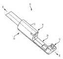
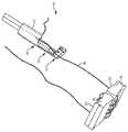
도 1은 일 실시예에 따른 봉합사 패싱 장치(suture passing device)의 원위단의 사시 평면도 도식적 표현(perspective top view schematic representation)이다.
도 2는 일 실시예에 따른, 후퇴된 위치 및 연장된 위치 사이, 로드된(loaded) 구성에서 장치의 그립 부분의 클로즈업(close-up) 사시 평면도 도식적 표현이다.
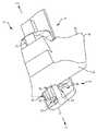
도 3은 일 실시예에 따른, 후퇴된 위치, 로드된 구성에서 클램프 튜브(clmap tube)의 원위단의 클로즈업 사시 측면도 도식적 표현(perspective side view schematic representation)이다.
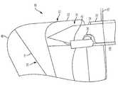
도 4는 일 실시예에 따른, 조직(tissue) 주위의 후퇴된 위치, 로드된 구성에서 장치의 사시 측면도 도시적 표현이다.
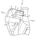
도 5는 일 실시예에 따른 장치의 몸체의 봉합사 홀딩 부분 안에 있는 니들의 클로즈업 사시 평면도 도식적 표현이다.
도 6은 일 실시예에 따른 장치의 봉합사 홀딩 부분의 토글 게이트(toggle gate)의 사시 측면도 도식적 표현이다.
도 7은 일 실시예에 따른 장치의 봉합사 홀딩 부분의 원위 죠(jaw)의 단면 (cross-sectional) 사시 측면도 도식적 표현이다.
도 8은 일 실시예에 따른, 연장된 위치, 로드된 구성에서 니들 및 언록 상태(unlocked state)에서 토글 게이트의 단면 사시 측면도 도식적 표현이다.
도 9는 일 실시예에 따른, 연장된 위치, 언로드된 구성(unloaded configuration)에서 니들 및 록 상태(locked state)에서 토글 게이트의 단면 사시 측면도 도식적 표현이다.
도 10은 일 실시예에 따른, 후퇴된 위치 및 연장된 위치 사이, 언로드된 구성에서 니들 및 록 상태에서 토글 게이트의 단면 사시 측면도 도식적 표현이다.
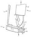
도 11은 일 실시예에 따른, 후퇴된 위치, 언로드된 구성에서 니들의 사시 측면도 도식적 표현이다.
도 12는 일 실시예에 따른, 연장된 위치, 언로드된 구성에서 니들 및 록 상태에서 토글 게이트의 사시 평면도 도식적 표현이다.
도 13은 일 실시예에 따른, 도 12의 장치의 원위단의 단면 측면도 도식적 표현이다.
도 14는 일 실시예에 따른, 연장된 위치, 로드된 구성에서 니들 및 언록 상태에서 토글 게이트의 단면 사시 측면도 도식적 표현이다.
도 15는 도 14의 니들의 원위단의 클로즈업 단면 측면도 도식적 표현이다.
도 16은 일 실시예에 따라, 조직으로부터 제거된 장치 및 후퇴된 위치, 로드된 구성에서 니들의 사시도 도시적 표현이다.
도 17은 다른 실시예에 따라, 조직으로부터 제거된 장치 및 후퇴된 위치, 로드된 구성에서 니들의 사시도 도식적 표현이다.
도 18은 대안적인 실시예에서, 후퇴된 위치 및 연장된 위치 사이, 언로드된 구성에서 니들의 사시 측면도 도시적 표현이다.
도 19는 대안적인 실시예에 따라 연장된 위치, 언로드된 구성에서 니들의 사시 측면도 도식적 표현이다.
도 20은 대안적인 실시예에서, 후퇴된 위치 및 연장된 위치 사이, 로드된 구성에서 니들의 사시 측면도 도식적 표현이다.
도 21은 대안적인 실시예에서, 후퇴된 위치 및 연장된 위치 사이, 언로드된 구성에서 니들의 클로즈업 사시 평면도 도식적 표현이다.One or more aspects of the invention are particularly pointed out and explicitly claimed by way of examples within the claims at the conclusion of the specification. The foregoing and other objects, features, and advantages of the invention are apparent from the following description in conjunction with accompanying drawings.
1 is a perspective top view schematic representation of a distal end of a suture passing device according to one embodiment;
2 is a close-up isometric top view schematic representation of a grip portion of the device in a loaded configuration, between a retracted position and an extended position, according to one embodiment.
3 is a close-up perspective side view schematic representation of a distal end of a clmap tube in a retracted position, loaded configuration, according to one embodiment.
4 is a perspective side view schematic representation of a device in a retracted position around tissue, loaded configuration, according to one embodiment;
5 is a close-up isometric top view schematic representation of a needle in a suture holding portion of the body of the device according to one embodiment;
6 is a perspective side view schematic representation of a toggle gate of a suture holding portion of a device according to one embodiment;
7 is a schematic representation of a cross-sectional isometric side view of a distal jaw of a suture holding portion of a device according to one embodiment.
8 is a cross-sectional isometric side view schematic representation of a needle in an extended position, a loaded configuration, and a toggle gate in an unlocked state, according to one embodiment.
9 is a cross-sectional isometric side view schematic representation of a toggle gate in an extended position, a needle in an unloaded configuration, and a locked state, according to one embodiment.
10 is a cross-sectional isometric side view schematic representation of a toggle gate in a needle and locked state in an unloaded configuration, between a retracted position and an extended position, according to one embodiment.
11 is a schematic representation of a perspective side view of a needle in a retracted position, unloaded configuration, according to one embodiment.
12 is a perspective top view schematic representation of a toggle gate in a needle and locked state in an extended position, an unloaded configuration, according to one embodiment.
13 is a schematic representation of a cross-sectional side view of the distal end of the device of FIG. 12 , according to one embodiment.
14 is a cross-sectional isometric side view schematic representation of a toggle gate in an extended position, needle in a loaded configuration, and an unlocked state, according to one embodiment.
15 is a schematic representation of a close-up cross-sectional side view of the distal end of the needle of FIG. 14 ;
16 is a perspective schematic representation of a device removed from tissue and a needle in a retracted position, loaded configuration, in accordance with one embodiment.
17 is a perspective schematic representation of a device removed from tissue and a needle in a retracted position, loaded configuration, in accordance with another embodiment.
18 is a isometric side view schematic representation of a needle in an unloaded configuration, between a retracted position and an extended position, in an alternative embodiment;
19 is a schematic representation of a perspective side view of a needle in an extended position, unloaded configuration, in accordance with an alternative embodiment;
20 is a schematic representation of a perspective side view of a needle in a loaded configuration, between a retracted position and an extended position, in an alternative embodiment;
21 is a close-up isometric top view schematic representation of a needle in an unloaded configuration, between a retracted position and an extended position, in an alternative embodiment;
본 발명의 측면들 및 특정 특징들, 장점들, 및 그것의 세부사항들은, 참조 도면들에 도시된 비한정적인 예시들에 관하여 아래에 충분히 더 설명된다. 잘 알려진 구조들(structures)의 설명들은 상세한 본 발명을 불필요하게 불명료하게 하지 않도록 생략된다. 그러나, 본 발명의 측면들을 나타내면서(indicating) 상세한 설명 및 특정 비한정적인 예시들은, 단지 설명(illustration)의 방식으로 주어진 것이며, 한정의 방식으로 주어진 것이 아님이 이해되어야 한다. 근본적인 발명 개념들의 사상 및/또는 범위 내에서 다양한 대체물들, 변경들, 부가물들, 및/또는 배열들이 이 개시로부터 통상의 기술자에게 명백해질 것이다.Aspects of the invention and certain features, advantages, and details thereof are fully described below with respect to non-limiting examples shown in the reference drawings. Descriptions of well-known structures are omitted so as not to unnecessarily obscure the detailed invention. It should be understood, however, that the detailed description and specific non-limiting examples indicating aspects of the invention have been given by way of illustration only and not by way of limitation. Various substitutions, changes, additions, and/or arrangements within the spirit and/or scope of the underlying inventive concepts will become apparent to those skilled in the art from this disclosure.
이제 도 1을 참조하면, 일 실시예에 따른 봉합사 패싱 장치의 원위단의 사시 평면도 도식적 표현이 도시된다. 도 1은 봉합사 패싱 장치(10)의 원위단(14)을 따라 연장하는 몸체(12)를 포함하는 봉합사 패싱 장치(10)를 도시한다. 특히, 몸체(12)는 장치(10)의 중심(central) 종방향(longitudinal) 축 x-x를 따라 연장한다. 장치(10)의 몸체(12)는 근위(proximal) 그립 부분(16) 및 원위(distal) 봉합사 홀딩 부분 (18)을 포함한다. 도 1에서 도시된 바와 같이, 봉합사 홀딩 부분(18)은 몸체(12)의 가장(most) 원위 부분을 포함한다. 도 1의 실시예에서 더 도시된 바와 같이, 그립 부분(16) 및 봉합사 홀딩 부분(18)은 그립 부분(16) 및 봉합사 홀딩 부분(18) 사이 몸체(12) 안에 리세스(20)가 있도록 이격되어있다. 리세스(20)는 봉합사 홀딩 부분(18) 및 그립 부분(16) 사이에 조직, 생물학적 몸체, 또는 다른 객체가 배치될(placed) 수 있도록 구성되거나 다른 크기로 설정된다(sized). 여기서 상세하게 설명된 바와 같이, 그립 부분(16) 및 봉합사 홀딩 부분(18)은 장치(10)의 리로딩 및 조직(생물학적 몸체 또는 객체)으로부터 장치(10)의 회수 없이 완전한 스티치들의 형성을 가능케 하는 특징들을 포함한다.Referring now to FIG. 1 , a perspective top view schematic representation of a distal end of a suture passing device according to one embodiment is shown. 1 shows a
이제 도 2를 참조하면, 일 실시예에 따라, 후퇴된 위치 및 연장된 위치 사이에서, 로드된 구성에서 장치(10)의 그립 부분(16)의 클로즈업 사시 평면도 도식적 표현이 도시된다. 도 2에 도시된 실시예에서, 그립 부분(16)은 봉합사 홀딩 부분(18)을 향해 중심 종방향 축 x-x에 실질적으로(substantially) 평행한 방향으로 원위로 연장하는 클램프 튜브(clamp tube)(22)를 포함한다. 묘사된 실시예에서, 클램프 튜브(22)는 리세스(20)에서 조직 또는 다른 생물학적 몸체와 맞물리기(engaging) 위해 클램프 튜브의 원위단(26)에 하나 이상의 돌출부들(protrusions)(24)을 포함한다. 그러나, 클램프 튜브(22)는 원한다면, (돌출부(24)가 없는) 매끄러운(smooth) 원위단(26)을 가질 수도 있다.Referring now to FIG. 2 , there is shown a close-up isometric top view schematic representation of
계속 도 2를 참조하면, 그립 부분(16)은 또한 중심 종방향 축 x-x에 평행한 방향으로 클램프 튜브(22)를 통해 연장하는 이동가능한(movable) (예를 들어, 슬라이드 가능한(slidable)) 튜브 또는 튜브형 피복(28)을 추가로 포함한다. 피복(28)은 클램프 튜브(22)의 제1 내부 볼륨(first inner volume)의 적어도 부분에서 연장한다. 또한, 묘사된 실시예에서도 도시된 바와 같이, 피복(28)은 이동가능한(예를 들어, 슬라이드 가능한) 니들(34)을 위하여 구성되고 다른 크기로 설정되는 제2 내부 볼륨(32) (도시되지 않음)을 포함한다. 도 2에 도시된 바와 같이, 니들은 피복(28)의 제2 내부 볼륨(32) 내에서 연장하며, 중심 종방향 축 x-x에 평행한 방향으로 연장한다. 니들(34)은 니들의 원위단(38)에 노치(36)를 포함한다. 노치(36)는 봉합사(40) (또는 다른 유사한(comparable) 스티칭 재료)를 수용(accommodate)하기 위하여 크기가 설정되거나 다른 치수로 설정된다(dimensioned).With continued reference to FIG. 2 ,
도 2에서 도시된 바와 같이, 봉합사(40)가 니들(34)에서 노치(36)를 통해 연장하고 노치(36)가 피복(28)의 원위단에 인접되는(abutted) 경우, 니들(34)은 로드된 구성에서 봉합사(40)를 잡고(grab) 고정(secure)한다. 피복(28)의 원위단은 근접(adjacent)하고 인접(abutting)하는 노치(36) 내에서 봉합사(40)를 제자리에 홀드(hold)한다. 일 실시예에서, 인장 메커니즘(tensioning mechanism)은 로드된 구성에서 노치(36)에 대해 피복(28)을 제자리에 홀드한다. 인장 메커니즘은 예를 들어, 클램프 튜브(22) 내의 스프링일 수 있다.As shown in FIG. 2 , when
이제 도 3을 참조하면, 일 실시예에 따른, 후퇴된 위치, 로드된 구성에서 클램프 튜브(22)의 원위단(26)의 클로즈업 사시 측면도 도식적 표현이 도시된다. 후퇴된 위치 및 연장된 위치 사이 로드된 구성으로부터, 도 2에 도시된 바와 같이, 니들(34) 및 피복(28)은 봉합사 홀딩 부분(18)으로부터 멀어지는 중심 종방향 축 x-x에 평행한 축을 따라 근위로 이동된다. 도 3에 도시된 바와 같이, 니들(34) 및 피복(28)이 근위로 이동함에 따라, 니들(34) 및 피복(28)은(they) 로드된 구성, 후퇴된 위치로 클램프 튜브(22) 내로 회수된다. 묘사된 실시예에서, 클램프 튜브(22)는 한 쌍의 대향하는(opposing) 프롱들(prongs) 사이에(therebetween) 구멍(opening)을 갖는 한 쌍의 대향하는 프롱들을 가지면서, 포크(forked)될 수 있다. 클램프 튜브(22)의 포크된 원위단(26)은 니들(34) 및 피복(28)이 클램프 튜브(22) 안으로 근위로 회수되는 경우, 봉합사(40)가 프롱들(42) 사이의 구멍들(44)에서 연장하도록 허용한다. 묘사된 실시예에서, 봉합사(40)는 프롱들(42) 사이의 구멍들(44) 내에서 중심 종방향 축 x-x에 대략적으로(approximately) 수직(perpendicular)인 방향으로 연장한다. 따라서, 니들(34) 및 피복(28)은 봉합사(40)를 방해(disturbing)하지 않으면서 클램프 튜브(22) 내로 회수될 수 있다.Referring now to FIG. 3 , there is shown a close-up isometric side view schematic representation of the
이제 도 4를 참조하면, 일 실시예에 따라, 조직(46) 주위의 후퇴된 위치, 로드된 구성에서 장치(10)의 사시 측면도 도식적 표현이 도시된다. 봉합사(40)가 니들(34)의 노치(36) 내로 로드되고 (도 2), 니들(34) 및 피복(28)이 클램프 튜브(22) 내로 후퇴된 후 (도 3), 장치(10)는 스티칭을 위해 조직(46) 또는 다른 생물학적 몸체와 맞물릴 수 있다. 묘사된 실시예에서, 스티칭 될 조직(46)은 봉합사 홀딩 부분(18) 및 그립 부분(16) 사이에 몸체(12)의 리세스(20) 내에 배치된다. 조직(46)이 리세스(20) 내에 있는 경우, 클램프 튜브(22)는 조직(46)상의 제1 스티칭 위치와 접촉(contact)하고 맞물리기 위하여 중심 종방향 축 x-x에 평행한 축을 따라 원위로 전진된다. 묘사된 실시예에서, 클램프 튜브(22)의 원위단(26) 상에 있는 돌출부들(24)은 돌출부들(24)이 조직(46)과 맞물릴 때까지 클램프 튜브(22)와 함께 원위로 전진된다.Referring now to FIG. 4 , a perspective side view schematic representation of
이제 도 5를 참조하면, 일 실시예에 따른 장치(10)의 몸체(12)의 봉합사 홀딩 부분(18)에서 니들(34)의 클로즈업 사시 평면도 도식적 표현이 도시된다. 봉합사 홀딩 부분(18)은 토글 게이트(50)를 갖는 원위 죠(48)를 포함한다. 도 5에 도시된 바와 같이, 토글 게이트(50)는 원위 죠(48)의 제1 측(52) 및 원위 죠(48)의 제2 측(54) 사이에서 연장한다. 묘사된 실시예에서, (도 6에 또한 도시됨) 원위 죠(48)는 토글 게이트(50)에서 토글 게이트 슬롯(slot)에 부합(correspond)하고 정렬(align)하는 죠 슬롯(56)을 가진다.Referring now to FIG. 5 , there is shown a close-up isometric top view schematic representation of a
도 4에 도시된 후퇴된 위치, 로드된 구성으로부터 피복(28), 니들(34), 및 고정된 봉합사(40)는 조직(46)의 근위측(proximal side)(60)으로부터 조직(46)의 원위측(62)으로 전진된다(advanced). 한번(once) 니들(34) 및 피복(28)이 조직(46)의 원위측(62)을 통해 연장하면, 니들(34) 및 피복(28)은 도 5에 도시된 연장된 위치, 로드된 구성으로 계속 연장한다. 연장된 위치, 로드된 구성에서, 니들(34)은 봉합사 홀딩 부분(18)의 원위 죠(48)의 제1 측(52) 및 제2 측(54) 사이 토글 게이트(50) 안으로 연장한다. 따라서, 니들(34)에 의해 운반된(carried) 봉합사(40)는 정렬된 토글 게이트 슬롯(58) 및 죠 슬롯(56)으로 들어간다(enter). 묘사된 실시예에서, 니들(34)이 원위로 연장하는 거리는 피복(28)이 원위로 연장하는 거리보다 크다. 결과적으로, 후퇴된 위치에서, 피복(28)은 더 이상 니들(34)의 노치(36)에 인접(abut)하지 않는다. 인장 메커니즘이 클램프 튜브(22) 내의 스프링인 일 실시예에서, 스프링 인장(tension)은 노치(36) 및 피복(28) 사이에서 해제된다(released). 인장이 해제됨에 따라, 봉합사(40)를 토글 게이트 슬롯(58) 및 죠 슬롯(56) 안으로 드랍시키며(dropping), 봉합사(40)는 노치(36)로부터 해제된다.From the retracted position, loaded configuration shown in FIG. 4 ,
이제 도 6 내지 도 7을 참조하면, 일 실시예에 따른 장치(10)의 봉합사 홀딩 부분(18)의 구성 요소들의 다양한 도면 도시적 표현이 도시된다. 도 6에 도시된 바와 같이, 토글 게이트(50)는 힌지(hinge)(51)를 통해 액츄에이터 로드(actuator rod)(64)에 연결된다. 액츄에이터 로드(64)는 봉합사 홀딩 부분(18)의 원위 죠(48)에 있는 회전 트랙(rotary track)(66)에서 토글 게이트(50)의 이동을 제어(control)한다. 묘사된 실시예에서, (도 8에 도시된 바와 같이) 토글 게이트(50)는 만곡되고(curved), 토글 게이트(50)가 언록 상태에 있는 경우 중심 종방향으로 x-x 축에 평행한 방향으로 연장하는 한 쌍의 프롱들(53)을 포함한다. 토글 게이트(50)로부터 프롱들(53)의 연장은 니들(34)로부터 봉합사(40)를 리시브(receive)하도록 구성되는 토글 게이트 슬롯(58)을 정의한다.Referring now to FIGS. 6-7 , various diagrammatic representations of the components of the
도 7은 일 실시예에 따라, 장치(10)의 봉합사 홀딩 부분(18)의 원위 죠(48)의 단면 사시 측면도를 도시한다. 회전 트랙(66)은 원위 죠(48)의 제2 측 (54) 및 제1 측(52) (도시되지 않음) 사이에서 연장한다. 도 7에 도시된 바와 같이, 회전 트랙(66)은 만곡된 토글 게이트(50)를 수용하기 위한 만곡된 부분(curved portion)(55) 및 실질적으로(substantially) 직선인(straight) 액츄에이터 로드(64)를 수용하기 위한 실질적으로 직선인 부분(57)을 가진다. 원위 죠(48)는 회전 트랙(66)의 만곡된 부분(55)을 정의하기 위한 근위 벽(proximal wall)(59) 및 원위 벽(distal wall)(61)을 포함한다. 근위 벽(59) 및 원위 벽(61) 사이의 거리는 토글 게이트(50)가 회전 트랙(66)의 만곡된 부분(55) 내에서 회전할 수 있도록 토글 게이트(50)의 폭보다 더 크다. 도 8 내지 도 10에 도시되는 바와 같이, 액츄에이터 로드(64)는 토글 게이트(50)가 각각 회전 트랙(66)으로부터 멀어지고 회전 트랙(66)을 향하여 이동하도록, 시계방향(clockwise) 및 반시계방향(counterclockwise) 방식(manner) 모두로 토글 게이트(50)를 이동시킨다.7 shows a cross-sectional isometric side view of the
이제 도 8 내지 도 10을 참조하면, 연장된 위치, 로드된 구성으로부터 후퇴된 위치, 언로드된 구성을 향하여 이동하는 봉합사 홀딩 부분(18)의 단면 측면도 도식적 표현이 도시된다. 도 8에 도시된 바와 같이, 니들(34)은 연장된 위치, 로드된 구성에서 토글 게이트(50) 내에서 연장한다. 연장된 위치, 로드된 구성에서, 토글 게이트(50)는 언록 상태에 있으며, 회전 트랙(66)으로부터 가장 먼 거리에 있다. 액츄에이터 로드(64)는 토글 게이트(50)를 도 8의 언록 상태로부터 도9의 록 상태로 이동시키도록 맞물린다. 도 8에서 도시된 바와 같이, 토글 게이트(50)가 언록 상태에 있는 경우, 토글 게이트(50)를 액츄에이터 로드(64)에 연결하는 힌지(hinge)(51)는 회전 트랙(66)의 만곡된 부분(55) 내에 있다. 토글 게이트(50)를 록 상태로 이동시키기 위하여, 회전 트랙(66)의 실질적으로 직선인 부분(57) 안으로 힌지(51)를 당기면서, 액츄에이터 로드(64)는 회전 트랙(66) 내에서 근위로 이동되거나 달리(otherwise) 당겨진다. 록 상태에서, 토글 게이트(50)는 회전 트랙(66)으로부터 가장 작은 거리에 있다. 도 9의 실시예에서, 토글 게이트(50)는 록 상태에서 원위 죠(48)의 원위 벽(66)에 인접한다. 토글 게이트(50)가 록 상태에 있는 경우, 도 10에 도시된 바와 같이, 니들(34) 및 피복(28)은 봉합사 홀딩 부분(18)으로부터(out from) 근위로(proximally) 후퇴될 수 있다.Referring now to FIGS. 8-10 , a cross-sectional side view schematic representation of a
이제 도 11을 간략히 참조하면, 후퇴된 위치, 언로드된 구성에서 장치(10)의 사시 측면도 도식적 표현이 도시된다. 니들(34) 및 피복(28)이 근위로 이동함에 따라, 도 10에 도시된 바와 같이, 니들(34) 및 피복(28)은 후퇴된 위치, 언로드된 구성에 도달할 때까지 중심 종방향 축 x-x에 평행한 축을 따라 클램프 튜브(22) 안으로 근위로 회수되거나 후퇴된다. 도 11에 도시된 후퇴된 위치, 언로드된 구성에서, 니들(34) 및 피복(28)은 니들(34)의 원위단(38)이 클램프 튜브(22) 내에 있도록 클램프 튜브(22) 안으로 전부(entirely) 회수된다. 또한, 후퇴된 위치, 언로드된 구성에서, 조직(46)은 봉합사 홀딩 부분(18) 및 그립 부분(16) 사이 몸체(12)에 있는 리세스(20)안에 남아(remain)있다. 도시된 바와 같이, (록 상태에서) 봉합사(40)의 제1 림(41)은 조직(46)을 통하여 연장하며, 토글 게이트(50)에서 고정된다.Referring now briefly to FIG. 11 , a perspective side view schematic representation of
이제 도 12를 참조하면, 연장된 위치, 언로드된 구성에서 장치(10)의 사시 평면도 도식적 표현이 도시된다. 도 11에 도시된 후퇴된 위치, 언로드된 구성으로부터, 장치(10)는 조직(46)을 따라 제2 스티칭 위치(second stitching location)로 이동된다. 일반적으로, 제2 스티칭 위치는 제1 스티칭 위치에 근접(adjacent)하고, 제1 및 제2 스티칭 위치 사이에 강한 연결을 형성하기 위해 제2 스티칭 위치에 충분히 근접하다. 그러나, 제1 및 제2 스티칭 위치들은 너무 근접(close)할 수 없어서, 봉합사(40) 상의 인장이 제1 스티칭 위치로부터 제2 스티칭 위치로 봉합사(40)를 당길 것이다. 장치(10)가 조직(46)을 따라 제2 스티칭 위치로 이동한 후, 클램프 튜브(22)는 클램프 튜브(22)가 조직(46)과 제2 스티칭 위치에서 맞물릴 때까지 조직(46)을 향하여 원위로(distally) 연장된다. 그 후에, 니들(34) 및 피복(28)은 제2 스티칭 위치에서 조직(46)을 통해 원위로 충분하게(fully) 연장되며, 토글 게이트(50) 내로 연장된다. 도 12에서, 토글 게이트(50)는 록 상태에 있고, 니들(34)은 토글 게이트(50) 내에서 연장된 위치, 언로드된 구성에 있다.Referring now to FIG. 12 , a perspective top view schematic representation of
이제 도 13을 참조하면, 도 12에 장치(10)의 원위단(14)의 단면 측면도 도식적 표현이 도시된다. 도 13에 도시된 바와 같이, 니들(34) 및 피복(28)은 조직(46)의 원위측(62)을 통하여 충분하게 연장되며, 토글 게이트(50) 안으로 연장된다. 위에서 설명한 것처럼, 토글 게이트(50)는 회전 트랙(66)에 대하여(against) 록 상태에 있다. 연장된 위치, 언로드된 구성에서, (록 상태에서) 니들(34)의 노치(36)는 토글 게이트 슬롯(58) 및 죠 슬롯(48)에서 봉합사(40) 위에 배치된다. 묘사된 실시예에서 도시된 바와 같이, 노치(36)는 대략적으로 봉합사(40)와 정렬된다(aligned).Referring now to FIG. 13 , a cross-sectional side view schematic representation of the
이제 도 14 내지 도 15를 참조하면, 언록 상태에서 토글 게이트(50)의 단면 측면도 도식적 표현이 도시된다. 도 13에 도시된 록 상태로부터, 토글 게이트(50)는 외과 의사(surgeon) (또는 다른 사용자)에 의한 액츄에이터 로드(64)의 이동을 통해 회전 트랙(66)에서 언록 상태로 회전된다. 토글 게이트(50)가 언록 상태로 이동되는 경우, 도 14에 도시된 바와 같이, 토글 게이트(50)는 니들(34)의 노치(36) 내에서 봉합사(40)를 이동시킨다. 도 15에 도시된 바와 같이, 인장 메커니즘에 의해 공급된 인장이 피복(28)을 노치(36)를 향하여 이동시키고, 피복(28) 및 니들(34)이 조직(46)의 원위측(distal side)(62)을 향해 근위 방향(proximal direction)으로 회수되고 당겨짐에 따라 봉합사(40)는 노치(36)에 의해 다시 캡쳐된다(captured).Referring now to FIGS. 14-15 , a cross-sectional side view schematic representation of a
이제 도 16을 참조하면, 일 실시예에 따른 조직(46)으로부터 제거된 후퇴된 위치, 로드된 구성에서 장치(10)의 사시 측면도 도식적 표현이 도시된다. 도 16에 도시된 바와 같이, 장치(10)는 절차의 완료 시(upon) 수술 부위에서 조직(46)으로부터 회수될 수 있다. 예를 들어, 외과 의사는 조직(46)을 접근(approximate)시키고 클로즈(close)하는 수술용 매듭의 형성(formation)에 따라(followed by), 장치(10)를 사용하여 고관절(hip joint)에서 매트리스 스티치(mattress stitch)를 완성할 수 있다. 장치(10)를 사용한 후, 외과 의사는 캐뉼라(cannula)를 통해 수술 부위로부터 장치(10)를 제거하면서, 고관절에 수술 부위로부터 장치(10)를 회수할 수 있다.Referring now to FIG. 16 , a isometric side view schematic representation of
도 17을 간략히 참조하면, 일 실시예에 따른, 조직(46)으로부터 제거된 후퇴된 위치, 로드된 구성에서 장치(10)의 사시도 도식적 표현이 도시된다. 대안적인 실시예에서, 외과 의사가 원한다면 더 많은 스티치들이 형성될 수 있다. 도 17에 도시된 바와 같이, 장치(10)를 하나 이상의 추가의(additional) 스티칭 위치들로 계속 이동시킴으로써 (도 11에 도시된 바와 같이) 조직에 더 많은 스티치들이 형성될 수 있다. 다시, 스티치들이 장치(10)로 형성되고 수술 매듭들이 조직(46)에 접근(approximate)하고 클로즈(close)하도록 묶여진 후에, 장치(10)는 캐뉼라를 통해 수술 부위로부터 제거될 수 있다.Referring briefly to FIG. 17 , a perspective schematic representation of
도 18 내지 도 21을 이제 참조하면, 장치(100)의 원위단(114)의 대안적인 실시예의 다양한 도면 도식적 표현들이 도시된다. 먼저 도 18을 참조하면, 도 2에 도시된 것과 유사하게, 장치(100)는 노치(136)를 가지는 니들(134) 및 튜브형 피복(128)을 갖는 그립 부분(116)을 포함한다. 묘사된 실시예에서, 장치(100)의 봉합사 홀딩 부분(118)은 중심 종방향 축 x-x에 실질적으로 수직(perpendicular)한 방향으로 연장하는 단부 조각(168)을 포함한다. 도 18에 도시된 바와 같이, 단부 조각(168)은 단부 조각(168)을 통해 연장하는 대략적인 중심 개구(170)를 포함한다. 개구(170)는 니들(134)이 개구(170)를 통하여 연장되고 후퇴될 수 있도록 니들(134)과 실질적으로 정렬된다.Referring now to FIGS. 18-21 , various diagrammatic representations of an alternative embodiment of the
계속 도 18을 참조하면, 봉합사(140)는 단부 조각(168) 위에 로드된다(loaded). 단부 조각(168)은 단부 조각으로부터 연장하는 프롱(172) (또는 다른 돌출부)을 포함한다. 장치를 사용하기 위해, 봉합사(140)는 봉합사의 제1 림(141)이 장치(100)의 제1 측(113) 상에서 연장하며, 봉합사(140)의 제2 림(143)이 장치(100)의 제2 측(115) 상에서 연장하도록 프롱(172) 주위에 래핑된다(wrapped).With continued reference to FIG. 18 ,
이제 도 19를 참조하면, 장치(100)가 후퇴된 위치 및 연장된 위치 사이 언로드된 구성에 있는 후에 (도 18), 니들(134)은 조직을 통하여 연장된다(명확성을 위하여 도시되지 않음). 도 19에 도시된 바와 같이, 니들(134)은 조직을 통하여 이동하며 (도시되지 않음) 단부 조각(168)에서 개구(170) 안으로 이동한다. 묘사된 실시예에서, 니들(134)이 개구(170)안으로 연장함에 따라 니들(134)의 노치(136)는 제1 방향(first direction)을 향한다(face). 도 19에 도시된 바와 같이, 니들(134)이 연장된 위치, 언로드된 구성에서 완전히 연장된 후, 도 20에 도시된 바와 같이, 니들(134)은 후퇴된다. 니들(134)이 후퇴됨으로써, 니들(134)의 노치(136)는 봉합사(140)의 제1 림(141)을 캐치(catch)하거나 잡는다. 도 1 내지 도 17에 도시된 장치(10)와 유사하게, 도 20에 장치(100)의 피복(128)은 니들(134)이 후퇴되면서 노치(136) 내에서 봉합사(140)의 제1 림(141)을 유지하고 고정한다. 니들(134)이 후퇴되는 경우, 피복(128)은 노치(136)에 인접(abut)하고 노치(136) 내에서 제1 림(141)을 고정한다. 도 1 내지 도 17에 도시된 장치를 참조하여 위에서 설명되듯이, 장치(100)의 그립 부분(116) 내의 스프링과 같은 인장 메커니즘은, 니들(134)의 노치(136)에서 피복(128)을 인장시킨다(tension). 니들(134)은 조직으로부터(도시되지 않음) 후퇴된 위치, 로드된 구성으로 완전히 회수된다.Referring now to FIG. 19 , after device 100 is in an unloaded configuration between a retracted position and an extended position ( FIG. 18 ), a
이제 도 21을 참조하면, 일 실시예에 따른 연장된 위치 및 후퇴된 위치 사이 언로드된 구성에서 장치(100)의 원위단(114)의 클로즈업 사시 평면도 도식적 표현이 도시된다. 니들(134)이 도 20의 조직(도시되지 않음)으로부터 충분하게 후퇴된 후, 니들(134)은 니들(134)의 노치(136)가 제2 방향(second direction)을 향하도록 회전된다. 일 실시예에서, 제1 방향은 니들(134)이 제1 방향으로부터 제2 방향으로 대략적으로 180 회전되도록 제2 방향과 대향(oppose)한다. 니들(134)의 노치(136)가 제2 방향을 향함으로, 도 21에 묘사된 바와 같이, 니들(134)은 조직(도시되지 않음)을 통하여 연장된다. 스티치를 완료하기 위해, 니들(134)은, 다시, 단부 조각(168)에서 개구(170)를 통하여 연장되고, 봉합사(140)의 제2 림(143)을 캐치하거나 잡기 위하여 개구(170)로부터(therefrom) 후퇴된다 (도 20에 도시되지만 반대 방향). 니들(134)에서 노치(136)가 봉합사(140)의 제2 림(143)을 캐치하거나 잡은 후, 니들(134)은 후퇴된다. 노치(136)에서 봉합사(140)의 제2 림(143)을 고정하면서, 니들(134)은 먼저 니들(134)에서 노치(136)가 피복(128)에 인접하도록 후퇴된다. 그 후, 니들(134)은 스티치를 완료하기 위하여 조직으로부터 충분하게 후퇴된다. 도 1 내지 도 17에서 도시된 실시예를 참조하여 설명된 바와 같이, 봉합사의 제1 림(141) 및 제2 림(143)은 장치로부터 회수되며, 조직에 접근하도록 인장되고, 스티치를 고정하기 위해 수술용 매듭 형성(surgical knot formation)으로 묶어진다.Referring now to FIG. 21 , a close-up isometric top view schematic representation of the
여기서 사용된 용어는 특정 실시예만을 설명하기 위한 것이며, 본 발명을 한정하는 것을 의도하지 않는다. 여기서 사용되는 바와 같이, 단수형들 "a", "an" 및 "the"은 문맥상 명백하게 다른 것을 지시하지 않는 한 복수형들을 포함한다. 용어 “포함하다(comprise)” (그리고 “포함한다(comprises)” 및 “포함하는(comprising)”과 같은 포함하다(comprise)의 임의의 형태), “가지다(have)”(그리고 “가진다(has)” 및 “가지는(having)”과 같은 가지다(have)의 임의의 형태), “포함하다(include)” (그리고 “포함한다(includes)” 및 “포함하는(including)”와 같은 포함하다(include)의 임의의 형태), “수용하다(contain)”(그리고 “수용한다(contains)” 및 “수용하는(containing)”과 같은 수용하다(contain)의 임의의 형태)는 개방형 연결 동사라고 더 이해되어질 것이다. 결과적으로, 장치 또는 방법은 하나 이상의 단계들 또는 구성들을 “포함한다(comprises)”, “가진다(has)”, “포함한다(contains)” 또는 “수용한다(contains)”. 마찬가지로, 하나 이상의 특징을 “포함하는(comprises)”, “가지는(has)”, “포함하는(includes)” 또는 “수용하는(contains)” 방법의 단계 또는 장치의 구성요소(element)는 이들 하나 이상의 특징들을 소유(possess)하지만, 이들 하나 이상의 특징들 만을 소유하는 것으로 한정되지는 않는다. 더 나아가, 특정 방식으로 구성되는 장치 또는 구조는 적어도 이 방식으로 구성되지만, 또한 나열되지 않은 방식들로도 구성될 수도 있다.The terminology used herein is for the purpose of describing specific embodiments only, and is not intended to limit the present invention. As used herein, the singular forms “a”, “an” and “the” include the plurals unless the context clearly dictates otherwise. The terms “comprise” (and any form of comprise such as “comprises” and “comprising”), “have” (and “has”) )” and any form of “have” such as “having”), “include” (and include such as “includes” and “including”) any form of include), "contain" (and any form of contain, such as "contains" and "containing") are more open-connecting verbs. will be understood Consequently, an apparatus or method “comprises”, “has”, “contains” or “contains” one or more steps or components. Likewise, a method step or element of a device “comprises”, “has”, “includes” or “contains” one or more features possesses the above characteristics, but is not limited to possessing only one or more of these characteristics. Furthermore, an apparatus or structure that is configured in a particular way is configured in at least this way, but may also be configured in ways not listed.
이하의 청구항들 에서는 모든 기능식 구성요소들(means or step plus function elements)의 대응하는 구조들, 재료들, 작용들(acts) 및 등가물(equivalents) (존재하는 경우)은 구체적으로 청구된 다른 청구항 구성요소들과 조합하여 기능을 수행하기 위한 임의의 구조, 재료 또는 작용(act)을 포함하는 것으로 의도된다. 본 발명의 설명은 예시(illustration) 및 설명(description)의 목적으로 제시되었으며, 개시된 형태 내에서 본 발명을 총망라하거나(exhaustive) 한정하려고 의도하는 것은 아니다. 본 발명의 사상 및 범위에서부터 벗어나지 않은 많은 수정들과 변형들이 통상의 기술자에게는 명백할 것이다. 상기 실시예는 발명의 하나 이상의 측면들 및 실제 적용(practical application)의 원칙들을 가장 잘 설명하기 위해, 그리고 통상의 기술자가 고려되는 특정 용도에 적합한 다양한 변형을 갖는 다양한 실시예들을 위한 본 발명의 하나 이상의 측면들을 이해할 수 있도록 하기 위하여 선택되고 설명되었다.In the following claims, the corresponding structures, materials, acts and equivalents (if any) of all means or step plus function elements refer to other claims specifically claimed. It is intended to include any structure, material, or act for performing a function in combination with the components. The description of the invention has been presented for purposes of illustration and description, and is not intended to be exhaustive or to limit the invention in the form disclosed. Many modifications and variations will be apparent to those skilled in the art without departing from the spirit and scope of the present invention. The above embodiment is one of several embodiments of the invention, with various modifications suitable for the particular use contemplated by those skilled in the art, and to best illustrate one or more aspects of the invention and principles of practical application. The above aspects have been selected and described in order to enable an understanding of them.
Claims (20)
Translated fromKorean봉합사 홀딩 부분(suture holding portion) 및 그립 부분(gripping portion)을 갖는 몸체(body)를 가지는 봉합사 패서 원위단(distal end); - 상기 그립 부분 및 상기 봉합사 홀딩 부분은 이격되며(spaced), 상기 그립 부분 및 상기 봉합사 홀딩 부분 사이(therebetween) 상기 몸체 안에서 리세스(recess)를 정의(defining)함 -
상기 봉합사 홀딩 부분을 향해 연장하는 상기 그립 부분의 튜브(tube);
상기 튜브 내에서 후퇴된 위치(retracted position)로부터 연장된 위치(extended position)로 슬라이드 가능한(slidable) 니들(needle); - 상기 니들(needle)은 니들 원위단에서 노치(notch)를 가짐 -
을 포함하고,
상기 후퇴된 위치에서 상기 니들 원위단은 상기 그립 부분의 상기 튜브 내에 있고, 상기 연장된 위치에서 상기 니들 원위단은 상기 봉합사 홀딩 부분 안으로 연장하고,
상기 봉합사 홀딩 부분은 액츄에이터 로드(actuator rod)에 힌지식으로(hingedly) 연결된 토글 게이트(toggle gate)를 포함하고, 상기 토글 게이트는 록 상태(locked state) 및 언록 상태(unlocked state) 사이에서 회전가능한(rotatable),
봉합사 패서.
In the suture passer (suture passer),
a suture passer distal end having a body having a suture holding portion and a gripping portion; - the grip portion and the suture holding portion are spaced, defining a recess in the body between the grip portion and the suture holding portion -
a tube of the grip portion extending towards the suture holding portion;
a needle slidable from a retracted position to an extended position within the tube; - the needle has a notch at the needle distal end;
including,
in the retracted position the needle distal end is within the tube of the grip portion, and in the extended position the needle distal end extends into the suture holding portion;
The suture holding portion includes a toggle gate hingedly connected to an actuator rod, the toggle gate being rotatable between a locked state and an unlocked state. (rotatable),
Suture passer.
상기 봉합사 홀딩 부분은 제1 측(first side) 및 제2 측(second side) 사이에서(therebetween) 연장하는 상기 토글 게이트를 갖는 제1 측 및 제2 측을 가지는 원위 죠(jaw)를 포함하는,
봉합사 패서.
According to claim 1,
wherein the suture holding portion comprises a distal jaw having a first side and a second side having the toggle gate extending therebetween a first side and a second side;
Suture passer.
상기 봉합사 홀딩 부분을 통하여 연장하는 회전 트랙(rotary track)을 더 포함하고, 상기 토글 게이트 및 상기 액츄에이터 로드는 상기 회전 트랙 내에서 슬라이드 가능하게(slidably) 배치된(disposed),
봉합사 패서.
4. The method of claim 3,
a rotary track extending through the suture holding portion, wherein the toggle gate and the actuator rod are slidably disposed within the rotation track;
Suture passer.
상기 튜브 내에서 이동 가능한(movable) 튜브형 피복(tubular sheath) 및 상기 튜브형 피복 내에서 슬라이드 가능한 상기 니들을 더 포함하고, 상기 튜브형 피복은 상기 니들 원위단 상에 상기 노치를 향해 인장되는(tensioned),
봉합사 패서.
According to claim 1,
a tubular sheath movable within the tube and the needle slidable within the tubular sheath, wherein the tubular sheath is tensioned towards the notch on the needle distal end;
Suture passer.
상기 봉합사 홀딩 부분은, 상기 연장된 위치에서 상기 니들 원위단이 단부 조각(end piece)의 개구 안으로 연장하도록, 상기 니들의 길이 방향과 정렬된 상기 개구를 가지는 상기 단부 조각을 포함하는,
봉합사 패서.
According to claim 1,
wherein the suture holding portion comprises the end piece having the opening aligned with the longitudinal direction of the needle such that in the extended position the needle distal end extends into the opening of the end piece;
Suture passer.
봉합사 홀딩 부분 및 그립 부분을 갖는 몸체를 가지는 상기 봉합사 패서의 봉합사 패서 원위단; - 상기 그립 부분 및 상기 봉합사 홀딩 부분은 이격되며(spaced), 상기 그립 부분 및 상기 봉합사 홀딩 부분 사이(therebetween) 상기 몸체 안에서 리세스(recess)를 정의함 -
상기 봉합사 홀딩 부분을 향해 연장하는 상기 그립 부분의 튜브;
상기 튜브 내에서 후퇴된 위치(retracted position)로부터 연장된 위치(extended position)로 슬라이드 가능한(slidable) 니들(needle); - 상기 니들(needle)은 니들 원위단에서 노치(notch)를 가짐 -
상기 후퇴된 위치에서 상기 니들 원위단은 상기 그립 부분의 상기 튜브 내에 있고, 상기 연장된 위치에서 상기 니들 원위단은 상기 봉합사 홀딩 부분 안으로 연장하며; 및
상기 봉합사 홀딩 부분의 제2 측 및 상기 봉합사 홀딩 부분의 제1 측 사이에서 연장하는 봉합사
를 포함하고,
상기 봉합사 홀딩 부분은 제1 측 및 제2 측 사이에서(therebetween) 연장하는 토글 게이트를 갖는 제1 측 및 제2 측을 가지는 원위 죠(jaw)를 포함하고, 상기 토글 게이트는 액츄에이터 로드에 힌지식으로 연결되며, 상기 토글 게이트는 록 상태 및 언록 상태 사이에서 회전가능한,
봉합사 패서.
In the loaded suture passer (loaded suture passer),
a suture passer distal end of the suture passer having a body having a suture holding portion and a grip portion; - the grip portion and the suture holding portion are spaced, defining a recess in the body between the grip portion and the suture holding portion -
a tube in the grip portion extending towards the suture holding portion;
a needle slidable from a retracted position to an extended position within the tube; - the needle has a notch at the needle distal end;
in the retracted position the needle distal end is within the tube of the grip portion, and in the extended position the needle distal end extends into the suture holding portion; and
a suture extending between a second side of the suture holding portion and a first side of the suture holding portion
including,
The suture holding portion includes a distal jaw having a first side and a second side having a toggle gate extending therebetween, the toggle gate hinged to an actuator rod. wherein the toggle gate is rotatable between a locked state and an unlocked state;
Suture passer.
상기 봉합사의 제1 림(first limb)은 상기 몸체의 제1 측을 따라 연장하고 상기 봉합사의 제2 림(second limb)은 상기 몸체의 제2 측을 따라 연장하는,
봉합사 패서.
8. The method of claim 7,
a first limb of the suture extends along a first side of the body and a second limb of the suture extends along a second side of the body;
Suture passer.
상기 후퇴된 위치 및 상기 연장된 위치 사이에서, 봉합사의 제1 림이 상기 니들의 상기 노치 내에 있는,
봉합사 패서.
8. The method of claim 7,
between the retracted position and the extended position, the first rim of suture is within the notch of the needle.
Suture passer.
상기 봉합사 홀딩 부분 상에 프롱(prong)을 더 포함하고, 상기 봉합사는 상기 프롱 주위에 래핑되는(wrapped),
봉합사 패서.
10. The method of claim 9,
further comprising a prong on the suture holding portion, wherein the suture is wrapped around the prong;
Suture passer.
상기 록 상태에서, 상기 봉합사는 상기 토글 게이트 내 슬롯(slot) 내에서 연장하는,
봉합사 패서.
8. The method of claim 7,
in the locked state, the suture extends within a slot in the toggle gate;
Suture passer.
상기 언록 상태에서, 상기 토글 게이트에 있는 상기 슬롯은 상기 봉합사가 상기 토글 게이트에 있는 상기 슬롯 및 상기 원위 죠(jaw)에 있는 상기 슬롯 내에서 연장하도록 상기 원위 죠에 있는 슬롯과 일직선이 되는(in alignment with),
봉합사 패서.
13. The method of claim 12,
In the unlocked state, the slot in the toggle gate is aligned with a slot in the distal jaw such that the suture extends within the slot in the toggle gate and the slot in the distal jaw. alignment with),
Suture passer.
상기 연장된 위치에서, 상기 니들의 상기 노치는 상기 원위 죠에 있는 상기 슬롯 및 상기 토글 게이트에 있는 상기 슬롯을 통해 연장하는 상기 봉합사와 정렬되는(aligned),
봉합사 패서.
14. The method of claim 13,
in the extended position, the notch of the needle is aligned with the suture extending through the slot in the distal jaw and the slot in the toggle gate;
Suture passer.
Applications Claiming Priority (7)
| Application Number | Priority Date | Filing Date | Title |
|---|---|---|---|
| US201762524776P | 2017-06-26 | 2017-06-26 | |
| US62/524,776 | 2017-06-26 | ||
| US201762549180P | 2017-08-23 | 2017-08-23 | |
| US201762549121P | 2017-08-23 | 2017-08-23 | |
| US62/549,121 | 2017-08-23 | ||
| US62/549,180 | 2017-08-23 | ||
| PCT/US2018/039406WO2019005733A1 (en) | 2017-06-26 | 2018-06-26 | Multiple suture passing device |
Publications (2)
| Publication Number | Publication Date |
|---|---|
| KR20200020829A KR20200020829A (en) | 2020-02-26 |
| KR102300736B1true KR102300736B1 (en) | 2021-09-13 |
Family
ID=62948379
Family Applications (1)
| Application Number | Title | Priority Date | Filing Date |
|---|---|---|---|
| KR1020207001544AActiveKR102300736B1 (en) | 2017-06-26 | 2018-06-26 | Multi-suture passing device |
Country Status (8)
| Country | Link |
|---|---|
| US (2) | US12201290B2 (en) |
| EP (1) | EP3644868A1 (en) |
| JP (1) | JP6941191B2 (en) |
| KR (1) | KR102300736B1 (en) |
| CN (1) | CN111182838B (en) |
| AU (1) | AU2018290735B2 (en) |
| CA (1) | CA3066474C (en) |
| WO (1) | WO2019005733A1 (en) |
Families Citing this family (1)
| Publication number | Priority date | Publication date | Assignee | Title |
|---|---|---|---|---|
| WO2024186996A2 (en)* | 2023-03-09 | 2024-09-12 | Noah Medical Corporation | Systems and methods for robotic endoluminal suturing instrument |
Citations (2)
| Publication number | Priority date | Publication date | Assignee | Title |
|---|---|---|---|---|
| WO2009089101A2 (en) | 2008-01-03 | 2009-07-16 | Wilson-Cook Medical, Inc. | Medical systems, devices and methods for endoscopically suturing perforations |
| WO2011008607A1 (en) | 2009-07-15 | 2011-01-20 | Pivot Medical, Inc. | Method and apparatus for treating a hip joint, including the provision and use of a novel suture passer |
Family Cites Families (9)
| Publication number | Priority date | Publication date | Assignee | Title |
|---|---|---|---|---|
| GB8422863D0 (en)* | 1984-09-11 | 1984-10-17 | Univ London | Sewing machine |
| EP2392265B2 (en)* | 2001-10-01 | 2017-04-26 | DePuy Mitek, Inc. | Suturing apparatus |
| US8172857B2 (en)* | 2004-08-27 | 2012-05-08 | Davol, Inc. | Endoscopic tissue apposition device and method of use |
| US7862582B2 (en)* | 2006-05-02 | 2011-01-04 | Ethicon Endo-Surgery, Inc. | Suture management |
| EP2033583B1 (en)* | 2007-08-27 | 2013-03-13 | Arthrex, Inc. | In-line suture passer |
| EP2389118B1 (en)* | 2009-01-26 | 2019-05-15 | Synthes GmbH | Bi-directional suture passer |
| US9198655B2 (en)* | 2009-07-15 | 2015-12-01 | Pivot Medical, Inc. | Method and apparatus for treating a hip joint, including the provision and use of a novel suture passer |
| US8523903B2 (en)* | 2009-10-30 | 2013-09-03 | Depuy Mitek, Llc | Partial thickness rotator cuff repair system and method |
| US10058325B2 (en)* | 2015-05-19 | 2018-08-28 | Arthrex, Inc. | Suture passer and method of tissue repair |
- 2018
- 2018-06-26CNCN201880055214.5Apatent/CN111182838B/enactiveActive
- 2018-06-26AUAU2018290735Apatent/AU2018290735B2/enactiveActive
- 2018-06-26KRKR1020207001544Apatent/KR102300736B1/enactiveActive
- 2018-06-26CACA3066474Apatent/CA3066474C/enactiveActive
- 2018-06-26EPEP18742672.1Apatent/EP3644868A1/enactivePending
- 2018-06-26WOPCT/US2018/039406patent/WO2019005733A1/ennot_activeCeased
- 2018-06-26JPJP2019571404Apatent/JP6941191B2/enactiveActive
- 2018-06-26USUS16/649,677patent/US12201290B2/enactiveActive
- 2025
- 2025-01-21USUS19/032,594patent/US20250160820A1/enactivePending
Patent Citations (3)
| Publication number | Priority date | Publication date | Assignee | Title |
|---|---|---|---|---|
| WO2009089101A2 (en) | 2008-01-03 | 2009-07-16 | Wilson-Cook Medical, Inc. | Medical systems, devices and methods for endoscopically suturing perforations |
| WO2011008607A1 (en) | 2009-07-15 | 2011-01-20 | Pivot Medical, Inc. | Method and apparatus for treating a hip joint, including the provision and use of a novel suture passer |
| US20110066165A1 (en)* | 2009-07-15 | 2011-03-17 | David Skinlo | Method and apparatus for treating a hip joint, including the provision and use of a novel suture passer |
Also Published As
| Publication number | Publication date |
|---|---|
| CA3066474C (en) | 2022-12-06 |
| EP3644868A1 (en) | 2020-05-06 |
| WO2019005733A1 (en) | 2019-01-03 |
| CN111182838A (en) | 2020-05-19 |
| CA3066474A1 (en) | 2019-01-03 |
| JP2020525117A (en) | 2020-08-27 |
| CN111182838B (en) | 2024-03-26 |
| AU2018290735A1 (en) | 2020-01-02 |
| KR20200020829A (en) | 2020-02-26 |
| JP6941191B2 (en) | 2021-09-29 |
| US20250160820A1 (en) | 2025-05-22 |
| US12201290B2 (en) | 2025-01-21 |
| US20210369263A1 (en) | 2021-12-02 |
| AU2018290735B2 (en) | 2021-04-01 |
Similar Documents
| Publication | Publication Date | Title |
|---|---|---|
| US11457905B2 (en) | Laparoscopic fascial closure system | |
| US10512454B2 (en) | Needle and snare guide apparatus for passing suture | |
| US9451951B2 (en) | Suture snare with retractable sleeve | |
| US9498208B2 (en) | Methods for passing multiple sutures through tissue | |
| CN103889345B (en) | Suturing device and method for suturing anatomical flaps | |
| AU702848B2 (en) | Endoscopic needle with suture retriever | |
| US7731726B2 (en) | Suture based vascular closure apparatus and method incorporating a pre-tied knot | |
| US6921408B2 (en) | Apparatus for sewing tissue and method of use | |
| US8202282B2 (en) | Knot pusher and suture retriever | |
| US5575800A (en) | Endoscopic suture system | |
| US20240173026A1 (en) | Automatically Reloading Suture Passer Devices That Prevent Entanglement | |
| US20030233106A1 (en) | Suture passing instrument | |
| US9700291B2 (en) | Capsule retractor | |
| US20040127915A1 (en) | Suture hoop system | |
| US20250160820A1 (en) | Multiple Suture Passing Device | |
| EP1720457A2 (en) | Suture manipulating and cutting implement | |
| US20150073442A1 (en) | Suture passer and method for hip labrum repair | |
| US20100324592A1 (en) | Suture-tying forceps | |
| US10070859B1 (en) | Systems and methods for passing a racking hitch through tissue | |
| HK1234301A1 (en) | Suturing devices and methods for suturing an anatomic valve | |
| HK1234301A (en) | Suturing devices and methods for suturing an anatomic valve |
Legal Events
| Date | Code | Title | Description |
|---|---|---|---|
| A201 | Request for examination | ||
| PA0105 | International application | Patent event date:20200116 Patent event code:PA01051R01D Comment text:International Patent Application | |
| PA0201 | Request for examination | ||
| PG1501 | Laying open of application | ||
| E902 | Notification of reason for refusal | ||
| PE0902 | Notice of grounds for rejection | Comment text:Notification of reason for refusal Patent event date:20210527 Patent event code:PE09021S01D | |
| E701 | Decision to grant or registration of patent right | ||
| PE0701 | Decision of registration | Patent event code:PE07011S01D Comment text:Decision to Grant Registration Patent event date:20210827 | |
| GRNT | Written decision to grant | ||
| PR0701 | Registration of establishment | Comment text:Registration of Establishment Patent event date:20210906 Patent event code:PR07011E01D | |
| PR1002 | Payment of registration fee | Payment date:20210907 End annual number:3 Start annual number:1 | |
| PG1601 | Publication of registration | ||
| PR1001 | Payment of annual fee | Payment date:20240729 Start annual number:4 End annual number:4 |