KR102300561B1 - Deposition system and processing system - Google Patents
Deposition system and processing systemDownload PDFInfo
- Publication number
- KR102300561B1 KR102300561B1KR1020200095940AKR20200095940AKR102300561B1KR 102300561 B1KR102300561 B1KR 102300561B1KR 1020200095940 AKR1020200095940 AKR 1020200095940AKR 20200095940 AKR20200095940 AKR 20200095940AKR 102300561 B1KR102300561 B1KR 102300561B1
- Authority
- KR
- South Korea
- Prior art keywords
- precursor
- reaction chamber
- gas supply
- supply unit
- tank
- Prior art date
- Legal status (The legal status is an assumption and is not a legal conclusion. Google has not performed a legal analysis and makes no representation as to the accuracy of the status listed.)
- Active
Links
Images


Classifications
- C—CHEMISTRY; METALLURGY
- C23—COATING METALLIC MATERIAL; COATING MATERIAL WITH METALLIC MATERIAL; CHEMICAL SURFACE TREATMENT; DIFFUSION TREATMENT OF METALLIC MATERIAL; COATING BY VACUUM EVAPORATION, BY SPUTTERING, BY ION IMPLANTATION OR BY CHEMICAL VAPOUR DEPOSITION, IN GENERAL; INHIBITING CORROSION OF METALLIC MATERIAL OR INCRUSTATION IN GENERAL
- C23C—COATING METALLIC MATERIAL; COATING MATERIAL WITH METALLIC MATERIAL; SURFACE TREATMENT OF METALLIC MATERIAL BY DIFFUSION INTO THE SURFACE, BY CHEMICAL CONVERSION OR SUBSTITUTION; COATING BY VACUUM EVAPORATION, BY SPUTTERING, BY ION IMPLANTATION OR BY CHEMICAL VAPOUR DEPOSITION, IN GENERAL
- C23C16/00—Chemical coating by decomposition of gaseous compounds, without leaving reaction products of surface material in the coating, i.e. chemical vapour deposition [CVD] processes
- C23C16/44—Chemical coating by decomposition of gaseous compounds, without leaving reaction products of surface material in the coating, i.e. chemical vapour deposition [CVD] processes characterised by the method of coating
- C23C16/448—Chemical coating by decomposition of gaseous compounds, without leaving reaction products of surface material in the coating, i.e. chemical vapour deposition [CVD] processes characterised by the method of coating characterised by the method used for generating reactive gas streams, e.g. by evaporation or sublimation of precursor materials
- C—CHEMISTRY; METALLURGY
- C23—COATING METALLIC MATERIAL; COATING MATERIAL WITH METALLIC MATERIAL; CHEMICAL SURFACE TREATMENT; DIFFUSION TREATMENT OF METALLIC MATERIAL; COATING BY VACUUM EVAPORATION, BY SPUTTERING, BY ION IMPLANTATION OR BY CHEMICAL VAPOUR DEPOSITION, IN GENERAL; INHIBITING CORROSION OF METALLIC MATERIAL OR INCRUSTATION IN GENERAL
- C23C—COATING METALLIC MATERIAL; COATING MATERIAL WITH METALLIC MATERIAL; SURFACE TREATMENT OF METALLIC MATERIAL BY DIFFUSION INTO THE SURFACE, BY CHEMICAL CONVERSION OR SUBSTITUTION; COATING BY VACUUM EVAPORATION, BY SPUTTERING, BY ION IMPLANTATION OR BY CHEMICAL VAPOUR DEPOSITION, IN GENERAL
- C23C16/00—Chemical coating by decomposition of gaseous compounds, without leaving reaction products of surface material in the coating, i.e. chemical vapour deposition [CVD] processes
- C23C16/02—Pretreatment of the material to be coated
- C23C16/0227—Pretreatment of the material to be coated by cleaning or etching
- C23C16/0245—Pretreatment of the material to be coated by cleaning or etching by etching with a plasma
- C—CHEMISTRY; METALLURGY
- C23—COATING METALLIC MATERIAL; COATING MATERIAL WITH METALLIC MATERIAL; CHEMICAL SURFACE TREATMENT; DIFFUSION TREATMENT OF METALLIC MATERIAL; COATING BY VACUUM EVAPORATION, BY SPUTTERING, BY ION IMPLANTATION OR BY CHEMICAL VAPOUR DEPOSITION, IN GENERAL; INHIBITING CORROSION OF METALLIC MATERIAL OR INCRUSTATION IN GENERAL
- C23C—COATING METALLIC MATERIAL; COATING MATERIAL WITH METALLIC MATERIAL; SURFACE TREATMENT OF METALLIC MATERIAL BY DIFFUSION INTO THE SURFACE, BY CHEMICAL CONVERSION OR SUBSTITUTION; COATING BY VACUUM EVAPORATION, BY SPUTTERING, BY ION IMPLANTATION OR BY CHEMICAL VAPOUR DEPOSITION, IN GENERAL
- C23C16/00—Chemical coating by decomposition of gaseous compounds, without leaving reaction products of surface material in the coating, i.e. chemical vapour deposition [CVD] processes
- C23C16/44—Chemical coating by decomposition of gaseous compounds, without leaving reaction products of surface material in the coating, i.e. chemical vapour deposition [CVD] processes characterised by the method of coating
- C23C16/4412—Details relating to the exhausts, e.g. pumps, filters, scrubbers, particle traps
- C—CHEMISTRY; METALLURGY
- C23—COATING METALLIC MATERIAL; COATING MATERIAL WITH METALLIC MATERIAL; CHEMICAL SURFACE TREATMENT; DIFFUSION TREATMENT OF METALLIC MATERIAL; COATING BY VACUUM EVAPORATION, BY SPUTTERING, BY ION IMPLANTATION OR BY CHEMICAL VAPOUR DEPOSITION, IN GENERAL; INHIBITING CORROSION OF METALLIC MATERIAL OR INCRUSTATION IN GENERAL
- C23C—COATING METALLIC MATERIAL; COATING MATERIAL WITH METALLIC MATERIAL; SURFACE TREATMENT OF METALLIC MATERIAL BY DIFFUSION INTO THE SURFACE, BY CHEMICAL CONVERSION OR SUBSTITUTION; COATING BY VACUUM EVAPORATION, BY SPUTTERING, BY ION IMPLANTATION OR BY CHEMICAL VAPOUR DEPOSITION, IN GENERAL
- C23C16/00—Chemical coating by decomposition of gaseous compounds, without leaving reaction products of surface material in the coating, i.e. chemical vapour deposition [CVD] processes
- C23C16/44—Chemical coating by decomposition of gaseous compounds, without leaving reaction products of surface material in the coating, i.e. chemical vapour deposition [CVD] processes characterised by the method of coating
- C23C16/4401—Means for minimising impurities, e.g. dust, moisture or residual gas, in the reaction chamber
- C23C16/4405—Cleaning of reactor or parts inside the reactor by using reactive gases
- C—CHEMISTRY; METALLURGY
- C23—COATING METALLIC MATERIAL; COATING MATERIAL WITH METALLIC MATERIAL; CHEMICAL SURFACE TREATMENT; DIFFUSION TREATMENT OF METALLIC MATERIAL; COATING BY VACUUM EVAPORATION, BY SPUTTERING, BY ION IMPLANTATION OR BY CHEMICAL VAPOUR DEPOSITION, IN GENERAL; INHIBITING CORROSION OF METALLIC MATERIAL OR INCRUSTATION IN GENERAL
- C23C—COATING METALLIC MATERIAL; COATING MATERIAL WITH METALLIC MATERIAL; SURFACE TREATMENT OF METALLIC MATERIAL BY DIFFUSION INTO THE SURFACE, BY CHEMICAL CONVERSION OR SUBSTITUTION; COATING BY VACUUM EVAPORATION, BY SPUTTERING, BY ION IMPLANTATION OR BY CHEMICAL VAPOUR DEPOSITION, IN GENERAL
- C23C16/00—Chemical coating by decomposition of gaseous compounds, without leaving reaction products of surface material in the coating, i.e. chemical vapour deposition [CVD] processes
- C23C16/44—Chemical coating by decomposition of gaseous compounds, without leaving reaction products of surface material in the coating, i.e. chemical vapour deposition [CVD] processes characterised by the method of coating
- C23C16/448—Chemical coating by decomposition of gaseous compounds, without leaving reaction products of surface material in the coating, i.e. chemical vapour deposition [CVD] processes characterised by the method of coating characterised by the method used for generating reactive gas streams, e.g. by evaporation or sublimation of precursor materials
- C23C16/4481—Chemical coating by decomposition of gaseous compounds, without leaving reaction products of surface material in the coating, i.e. chemical vapour deposition [CVD] processes characterised by the method of coating characterised by the method used for generating reactive gas streams, e.g. by evaporation or sublimation of precursor materials by evaporation using carrier gas in contact with the source material
- C23C16/4482—Chemical coating by decomposition of gaseous compounds, without leaving reaction products of surface material in the coating, i.e. chemical vapour deposition [CVD] processes characterised by the method of coating characterised by the method used for generating reactive gas streams, e.g. by evaporation or sublimation of precursor materials by evaporation using carrier gas in contact with the source material by bubbling of carrier gas through liquid source material
- C—CHEMISTRY; METALLURGY
- C23—COATING METALLIC MATERIAL; COATING MATERIAL WITH METALLIC MATERIAL; CHEMICAL SURFACE TREATMENT; DIFFUSION TREATMENT OF METALLIC MATERIAL; COATING BY VACUUM EVAPORATION, BY SPUTTERING, BY ION IMPLANTATION OR BY CHEMICAL VAPOUR DEPOSITION, IN GENERAL; INHIBITING CORROSION OF METALLIC MATERIAL OR INCRUSTATION IN GENERAL
- C23C—COATING METALLIC MATERIAL; COATING MATERIAL WITH METALLIC MATERIAL; SURFACE TREATMENT OF METALLIC MATERIAL BY DIFFUSION INTO THE SURFACE, BY CHEMICAL CONVERSION OR SUBSTITUTION; COATING BY VACUUM EVAPORATION, BY SPUTTERING, BY ION IMPLANTATION OR BY CHEMICAL VAPOUR DEPOSITION, IN GENERAL
- C23C16/00—Chemical coating by decomposition of gaseous compounds, without leaving reaction products of surface material in the coating, i.e. chemical vapour deposition [CVD] processes
- C23C16/44—Chemical coating by decomposition of gaseous compounds, without leaving reaction products of surface material in the coating, i.e. chemical vapour deposition [CVD] processes characterised by the method of coating
- C23C16/448—Chemical coating by decomposition of gaseous compounds, without leaving reaction products of surface material in the coating, i.e. chemical vapour deposition [CVD] processes characterised by the method of coating characterised by the method used for generating reactive gas streams, e.g. by evaporation or sublimation of precursor materials
- C23C16/4485—Chemical coating by decomposition of gaseous compounds, without leaving reaction products of surface material in the coating, i.e. chemical vapour deposition [CVD] processes characterised by the method of coating characterised by the method used for generating reactive gas streams, e.g. by evaporation or sublimation of precursor materials by evaporation without using carrier gas in contact with the source material
- C—CHEMISTRY; METALLURGY
- C23—COATING METALLIC MATERIAL; COATING MATERIAL WITH METALLIC MATERIAL; CHEMICAL SURFACE TREATMENT; DIFFUSION TREATMENT OF METALLIC MATERIAL; COATING BY VACUUM EVAPORATION, BY SPUTTERING, BY ION IMPLANTATION OR BY CHEMICAL VAPOUR DEPOSITION, IN GENERAL; INHIBITING CORROSION OF METALLIC MATERIAL OR INCRUSTATION IN GENERAL
- C23C—COATING METALLIC MATERIAL; COATING MATERIAL WITH METALLIC MATERIAL; SURFACE TREATMENT OF METALLIC MATERIAL BY DIFFUSION INTO THE SURFACE, BY CHEMICAL CONVERSION OR SUBSTITUTION; COATING BY VACUUM EVAPORATION, BY SPUTTERING, BY ION IMPLANTATION OR BY CHEMICAL VAPOUR DEPOSITION, IN GENERAL
- C23C16/00—Chemical coating by decomposition of gaseous compounds, without leaving reaction products of surface material in the coating, i.e. chemical vapour deposition [CVD] processes
- C23C16/44—Chemical coating by decomposition of gaseous compounds, without leaving reaction products of surface material in the coating, i.e. chemical vapour deposition [CVD] processes characterised by the method of coating
- C23C16/455—Chemical coating by decomposition of gaseous compounds, without leaving reaction products of surface material in the coating, i.e. chemical vapour deposition [CVD] processes characterised by the method of coating characterised by the method used for introducing gases into reaction chamber or for modifying gas flows in reaction chamber
- C23C16/45561—Gas plumbing upstream of the reaction chamber
- C—CHEMISTRY; METALLURGY
- C23—COATING METALLIC MATERIAL; COATING MATERIAL WITH METALLIC MATERIAL; CHEMICAL SURFACE TREATMENT; DIFFUSION TREATMENT OF METALLIC MATERIAL; COATING BY VACUUM EVAPORATION, BY SPUTTERING, BY ION IMPLANTATION OR BY CHEMICAL VAPOUR DEPOSITION, IN GENERAL; INHIBITING CORROSION OF METALLIC MATERIAL OR INCRUSTATION IN GENERAL
- C23C—COATING METALLIC MATERIAL; COATING MATERIAL WITH METALLIC MATERIAL; SURFACE TREATMENT OF METALLIC MATERIAL BY DIFFUSION INTO THE SURFACE, BY CHEMICAL CONVERSION OR SUBSTITUTION; COATING BY VACUUM EVAPORATION, BY SPUTTERING, BY ION IMPLANTATION OR BY CHEMICAL VAPOUR DEPOSITION, IN GENERAL
- C23C16/00—Chemical coating by decomposition of gaseous compounds, without leaving reaction products of surface material in the coating, i.e. chemical vapour deposition [CVD] processes
- C23C16/44—Chemical coating by decomposition of gaseous compounds, without leaving reaction products of surface material in the coating, i.e. chemical vapour deposition [CVD] processes characterised by the method of coating
- C23C16/52—Controlling or regulating the coating process
Landscapes
- Chemical & Material Sciences (AREA)
- Engineering & Computer Science (AREA)
- General Chemical & Material Sciences (AREA)
- Chemical Kinetics & Catalysis (AREA)
- Materials Engineering (AREA)
- Mechanical Engineering (AREA)
- Metallurgy (AREA)
- Organic Chemistry (AREA)
- Physics & Mathematics (AREA)
- Plasma & Fusion (AREA)
- Chemical Vapour Deposition (AREA)
Abstract
Translated fromKorean
Description
Translated fromKorean본 발명은 증착 시스템 및 공정 시스템에 관한 것이다.The present invention relates to a deposition system and a process system.
기판 상에 박막을 형성하는 대표적인 방법으로 화학 기상 증착(Chemical Vapor Deposition, CVD) 및 원자층 증착(Atomic Layer Deposition, ALD)이 있다. CVD 및 ALD 공정에서는 다양한 반응물들을 사용하여 기판 표면에 박막을 형성할 수 있다. 공정 과정에서 액체 반응물들은 일반적으로 기체 상태로 상변화되어 반응 챔버로 공급된다. 증착 공정이 완료된 후에는, 공정 배기물들이 배기단으로 배출된다. 다만, 액체 반응물을 공급량을 늘리기 위해 기화기를 사용하게 되면서 액체 반응물들을 공급하는 캐니스터(canister)의 교체 주기가 짧아지고, 공정 배기물들의 증가로 인해 펌프(pump) 교체 시기가 짧아지고 있다. 또한, 캐니스터와 펌프를 교체할 때에는 증착 설비를 정지해야 한다는 문제가 있는 바, 대량 생산 관점에서 증착 설비의 유지 및 관리가 용이하도록 증착 시스템을 개선할 필요가 있다.Representative methods of forming a thin film on a substrate include chemical vapor deposition (CVD) and atomic layer deposition (ALD). In CVD and ALD processes, a thin film can be formed on the surface of a substrate by using various reactants. During the process, the liquid reactants are generally phase-changed to a gaseous state and supplied to the reaction chamber. After the deposition process is completed, the process exhaust is discharged to the exhaust stage. However, as the vaporizer is used to increase the supply amount of the liquid reactant, the replacement cycle of the canister for supplying the liquid reactant is shortened, and the pump replacement period is shortened due to the increase of process exhaust. In addition, since there is a problem that the deposition equipment must be stopped when the canister and the pump are replaced, it is necessary to improve the deposition system to facilitate maintenance and management of the deposition equipment from the viewpoint of mass production.
본 발명의 기술적 사상이 이루고자 하는 과제 중 하나는, 대량 생산 관점에서 증착 설비의 유지 및 관리가 용이한 증착 시스템을 제공하고자 하는 데에 있다.One of the problems to be achieved by the technical idea of the present invention is to provide a deposition system that facilitates maintenance and management of deposition equipment from the viewpoint of mass production.
본 발명의 일 실시예에 따른 증착 시스템은, 반응 챔버, 상기 반응 챔버에 기체 상태의 제1 전구체를 공급하는 제1 가스 공급부, 상기 반응 챔버에 상기 제1 전구체와 반응하는 반응물을 공급하는 반응물 공급부, 및 상기 반응 챔버에서 나온 배기물을 배출하는 배기부를 포함하고, 상기 제1 가스 공급부는 순차적으로 연결되는 제1 서브 탱크, 제1 액체 유량 컨트롤러, 및 제1 기화기를 포함하고, 상기 제1 전구체는 제1 자동 충진 시스템에 의해 상기 제1 가스 공급부의 상기 제1 서브 탱크에 액체 상태로 충진되고, 상기 제1 서브 탱크, 상기 제1 액체 유량 컨트롤러, 및 상기 제1 기화기를 순차적으로 경유하여 상기 반응 챔버로 공급되며, 상기 배기부는 플라즈마 전처리 시스템이 적용되는 처리 공정 챔버, 펌프, 및 스크러버를 포함한다.A deposition system according to an embodiment of the present invention includes a reaction chamber, a first gas supply unit supplying a gaseous first precursor to the reaction chamber, and a reactant supply unit supplying a reactant reacting with the first precursor to the reaction chamber , and an exhaust for discharging the exhaust from the reaction chamber, wherein the first gas supply includes a first sub tank, a first liquid flow controller, and a first vaporizer that are sequentially connected, and the first precursor is filled in a liquid state in the first sub tank of the first gas supply unit by a first automatic filling system, and sequentially passes through the first sub tank, the first liquid flow controller, and the first vaporizer. It is supplied to a reaction chamber, and the exhaust includes a treatment process chamber to which a plasma pretreatment system is applied, a pump, and a scrubber.
본 발명의 일 실시예에 따른 증착 시스템은, 반응 챔버, 자동 충진 시스템을 이용하여 상기 반응 챔버에 적어도 하나의 전구체를 기체 상태로 공급하는 적어도 하나의 가스 공급부, 상기 반응 챔버에 상기 전구체와 반응하는 반응물을 공급하는 반응물 공급부, 및 상기 반응 챔버에서 나온 배기물을 배출하는 배기부; 를 포함하고, 상기 적어도 하나의 가스 공급부는 상기 전구체가 저장되는 서브 탱크, 상기 전구체를 기체 상태로 상기 반응 챔버에 공급하기 위한 기화기, 및 상기 기화기로 공급되는 상기 전구체의 양을 조절하는 액체 유량 컨트롤러를 포함하며, 상기 배기부는 처리 공정 챔버, 펌프, 및 스크러버를 포함하고, 상기 처리 공정 챔버는 플라즈마 전처리 시스템을 이용하여 상기 배기물의 화학적 구조를 변화시킨 뒤 상기 펌프를 통해 상기 배기물을 배출한다.A deposition system according to an embodiment of the present invention includes a reaction chamber, at least one gas supply unit supplying at least one precursor in a gaseous state to the reaction chamber using an automatic filling system, and reacting with the precursor in the reaction chamber a reactant supply unit for supplying a reactant, and an exhaust unit for discharging exhaust from the reaction chamber; The at least one gas supply unit includes a sub-tank in which the precursor is stored, a vaporizer for supplying the precursor to the reaction chamber in a gaseous state, and a liquid flow controller for controlling the amount of the precursor supplied to the vaporizer wherein the exhaust unit includes a treatment process chamber, a pump, and a scrubber, and the treatment process chamber changes a chemical structure of the exhaust by using a plasma pretreatment system and then discharges the exhaust through the pump.
본 발명의 일 실시예에 따른 공정 시스템은, 액체 상태의 공정 물질을 서브 탱크에 자동으로 충진하는 적어도 하나의 자동 충진 시스템, 상기 서브 탱크에 저장된 상기 공정 물질을 기체 상태로 반응 챔버에 공급하는 가스 공급 시스템, 및 플라즈마 방전을 유도하여 상기 반응 챔버에서 배출된 배기물의 화학적 구조를 변화시키도록 동작하는 플라즈마 전처리 시스템을 포함하고, 상기 가스 공급 시스템은 상기 서브 탱크와 상기 반응 챔버 사이에 순차적으로 연결된 액체 유량 컨트롤러 및 기화기를 동작시키며, 상기 액체 유량 컨트롤러는 상기 기화기에 공급하는 상기 공정 물질의 양을 조절한다.A process system according to an embodiment of the present invention includes at least one automatic filling system for automatically filling a sub-tank with a process material in a liquid state, and a gas for supplying the process material stored in the sub-tank to a reaction chamber in a gaseous state a supply system, and a plasma pretreatment system operative to induce a plasma discharge to change the chemical structure of exhaust exhaust from the reaction chamber, wherein the gas supply system is a liquid sequentially coupled between the sub-tank and the reaction chamber. Operate a flow controller and a vaporizer, wherein the liquid flow controller regulates the amount of the process material supplied to the vaporizer.
본 발명의 일 실시예에 따른 증착 시스템은, 캐니스터를 주기적으로 교체하는 방법 대신 서브 탱크에 적용되는 자동 충진 시스템(Auto Refill System, ARS)을 이용함으로써, 액체 반응액을 항시 공급 가능한 상태로 유지시킬 수 있다. 또한, 배기부에는 플라즈마 전처리 시스템(Pre Plasma treatment System, PPS)을 적용함으로써 펌프의 수명을 증가시키고 스크러버의 효율을 개선할 수 있다.The deposition system according to an embodiment of the present invention uses an Auto Refill System (ARS) applied to a sub tank instead of a method of periodically replacing a canister, thereby maintaining a liquid reaction solution in a state that can always be supplied. can In addition, by applying a plasma pretreatment system (Pre Plasma treatment System, PPS) to the exhaust unit, it is possible to increase the lifespan of the pump and improve the efficiency of the scrubber.
본 발명의 다양하면서도 유익한 장점과 효과는 상술한 내용에 한정되지 않으며, 본 발명의 구체적인 실시 형태를 설명하는 과정에서 보다 쉽게 이해될 수 있을 것이다.Various and advantageous advantages and effects of the present invention are not limited to the above, and will be more easily understood in the course of describing specific embodiments of the present invention.
도 1은 본 발명의 일 실시예에 따른 증착 시스템의 개략적인 블록도이다.
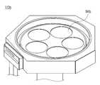
도 2a 내지 도 2c는 본 발명의 일 실시예에 따른 증착 시스템에서, 반응 챔버의 종류를 설명하기 위한 도면들이다.
도 3은 본 발명의 일 실시예에 따른 증착 시스템에서, 버블러의 동작을 설명하기 위한 도면이다.
도 4는 본 발명의 일 실시예에 따른 증착 시스템에서, 기화기의 동작을 설명하기 위한 도면이다.
도 5는 본 발명의 일 실시예에 따른 증착 시스템에서, 자동 충진 시스템의 동작을 설명하기 위한 개략적인 흐름도이다.
도 6은 본 발명의 일 실시예에 따른 증착 시스템에서, 배기물의 배출 과정을 설명하기 위한 개략적인 도면이다.
도 7은 본 발명의 일 실시예에 따른 증착 시스템에서, 플라즈마 전처리 시스템의 동작을 설명하기 위한 개략적인 흐름도이다.
도 8 내지 도 10은 본 발명의 일 실시예에 따른 증착 시스템의 개략적인 블록도이다.1 is a schematic block diagram of a deposition system according to an embodiment of the present invention.
2A to 2C are diagrams for explaining types of reaction chambers in a deposition system according to an embodiment of the present invention.
3 is a view for explaining an operation of a bubbler in a deposition system according to an embodiment of the present invention.
4 is a diagram for explaining an operation of a vaporizer in a deposition system according to an embodiment of the present invention.
5 is a schematic flowchart illustrating an operation of an automatic filling system in a deposition system according to an embodiment of the present invention.
6 is a schematic diagram for explaining a process of discharging exhaust in a deposition system according to an embodiment of the present invention.
7 is a schematic flowchart illustrating an operation of a plasma pretreatment system in a deposition system according to an embodiment of the present invention.
8 to 10 are schematic block diagrams of a deposition system according to an embodiment of the present invention.
이하, 첨부된 도면을 참조하여 본 발명의 바람직한 실시 형태들을 다음과 같이 설명한다.Hereinafter, preferred embodiments of the present invention will be described with reference to the accompanying drawings.
도 1은 본 발명의 일 실시예에 따른 증착 시스템의 개략적인 블록도이다.1 is a schematic block diagram of a deposition system according to an embodiment of the present invention.
도 1을 참조하면, 증착 시스템(1)은 반응 챔버(10), 가스 공급부(20), 배기부(30), 메인 탱크(40), 및 반응물 공급부(50)를 포함할 수 있다.Referring to FIG. 1 , the
본 발명의 일 실시예에 따른 증착 시스템(1)은 화학 기상 증착(CVD) 및/또는 원자층 증착(ALD) 공정이 진행되는 시스템일 수 있다. CVD 공정 및 ALD 공정은 공통적으로 전구체와 반응물을 반응 챔버(10)의 내부로 공급하여 반응시킴으로써 기판 상에 박막을 증착하는 과정으로 진행될 수 있다.The
전구체는 상온에서 액체 또는 고체 상태로 존재할 수 있고, 가스 공급부(20)에 포함된 일 구성에 의해 기화되어 기체 상태로 반응 챔버(10)에 공급될 수 있다. 다만 이는 일 실시예에 불과할 뿐 한정되지 않고, 전구체는 상온에서 기체 상태로 존재할 수도 있다. 본 발명의 일 실시예에 따른 증착 시스템(1)에서, 전구체는 액체 반응물일 수 있다. 일례로 전구체는 금속 유기 전구체(metal organic precursor)일 수 있고, 3, 4, 5족 원소로 구성될 수 있다. 다만 이는 일 실시예에 불과할 뿐 한정되지 않고, 실시예들에 따라 다른 원소들로 구성될 수도 있다.The precursor may exist in a liquid or solid state at room temperature, and may be vaporized by a component included in the
일반적인 증착 공정에서, 전구체를 기체 상태로 상변화시키기 위한 기화 장치로써 버블러(bubbler) 및/또는 기화기(vaporizer)가 이용될 수 있다. 일례로, 베이킹(baking) 방식을 이용하여 전구체를 기체 상태로 상변화시키고, 운반 가스를 이용하여 기체 전구체를 반응 챔버(10)로 공급할 수 있다. 한편, 운반 가스로 버블링(bubbling) 현상을 일으켜 액체 전구체를 기화시키고, 기체 전구체를 반응 챔버(10)로 공급할 수도 있다. 다만, 기화기를 사용하여 액체 전구체를 기체 상태로 상변화시켜야 할 수도 있다.In a general deposition process, a bubbler and/or a vaporizer may be used as a vaporization device for phase-changing a precursor into a gaseous state. For example, the precursor may be phase-changed into a gaseous state using a baking method, and the gaseous precursor may be supplied to the
전술한 기화 장치들 중 어떤 장치을 이용할 것인지는 액체 전구체의 증기압에 따라 달라질 수 있다. 일례로 증기압이 낮은 전구체의 경우, 버블러를 사용하여 액체 전구체를 기화시키는데 어려움이 있을 수 있고, 기화기를 사용하여야할 수 있다. 반면 증기압이 높은 전구체의 경우 베이킹 방식만으로 전구체를 기화시킬 수도 있다.Which of the above-described vaporization apparatuses is used may vary depending on the vapor pressure of the liquid precursor. For example, in the case of a precursor having a low vapor pressure, it may be difficult to vaporize the liquid precursor using a bubbler, and it may be necessary to use a vaporizer. On the other hand, in the case of a precursor having a high vapor pressure, the precursor may be vaporized only by a baking method.
한편, 기화기를 사용하여 액체 전구체를 기체 상태로 상변화시키는 경우, 버블러를 사용할 때보다 많은 양의 전구체를 반응 챔버(10)에 공급할 수 있다. 반응 챔버(10)에 공급되는 전구체의 양은 액체 유량 컨트롤러(Liquid Mass Flow Controller)에 의해 조절될 수 있다.Meanwhile, when the liquid precursor is phase-changed to a gaseous state using a vaporizer, a larger amount of the precursor may be supplied to the
일반적으로, 반응 챔버(10)에 공급되는 전구체는 캐니스터에 저장될 수 있다. 이 때, 공정이 진행됨에 따라 캐니스터 내부에 전구체가 소정의 양보다 적어지는 경우, 다시 공정을 진행하기 위해서는 캐니스터를 교체해야 할 수 있다. 한편, 캐니스터를 교체하기 위해서는 공정 설비를 정지해야 할 수 있다. 일례로, 공정 설비 정지 기간동안에는 캐니스터의 교체와 함께 배관 내부의 불순물을 제거하는 클리닝 과정이 진행될 수 있다.In general, the precursor supplied to the
한편, 증착 공정이 진행되는 동안 및/또는 증착 공정이 완료된 후, 반응 챔버(10)의 배기단으로 배기물들이 배출될 수 있다. 일례로, 배기물들은 증착 공정 과정에서 반응하지 못한 기체 반응물이나 반응한 이후의 부산물들을 포함할 수 있다. 배기물들은 쉽게 고체 형태로 상변화하여 반응 챔버(10)의 배기단에 연결되는 펌프(32)에 축적될 수 있고, 무리를 줄 수 있다. 이에 따라 소모된 펌프를 교체하기 위해서는 공정 설비를 정지해야 할 수 있다.Meanwhile, while the deposition process is in progress and/or after the deposition process is completed, exhaust gases may be discharged to the exhaust end of the
본 발명의 일 실시예에 따른 증착 시스템(1)에서, 반응 챔버(10)는 증착 공정이 진행되는 증착 챔버를 포함할 수 있다. 일례로, 증착 공정은 화학 기상 증착(CVD) 및/또는 원자층 증착(ALD) 공정일 수 있다. 다만, 이는 일 실시예에 불과할 뿐 한정되지 않고, 본 발명의 일 실시예에 따른 증착 시스템(1)의 반응 챔버(10)는 가스 분사가 이용되는 다른 공정이 진행되는 챔버를 포함할 수도 있다. 일례로, 반응 챔버(10)는 CMP 공정 후 세정 가스를 분사하여 세정을 진행하는 연마 공정 챔버, 소스 가스의 라디칼과 이온을 포함하는 플라즈마 등을 이용하여 웨이퍼 및/또는 웨이퍼 상에 형성된 소자층들 중 적어도 일부 영역을 제거하는 식각 공정 챔버 등을 포함할 수 있다. 한편, 증착 공정 이외의 기타 공정이 진행되는 경우, 반응 챔버(10)로 공급되는 기체는 전구체로 한정되지 않을 수 있다.In the
본 발명의 일 실시예에 따른 증착 시스템(1)에서, 반응 챔버(10)로 공급되는 액체 전구체는 메인 탱크(40)에 저장되어 있을 수 있다. 메인 탱크(40)에 저장되어 있던 액체 전구체는 자동 충진 시스템(Auto Refill System, ARS)에 의해 가스 공급부(20)로 충진될 수 있다. 일례로, 자동 충진 시스템(ARS)은 공정과 공정 사이에 동작할 수 있다. 일례로, 자동 충진 시스템(ARS)이 동작하면 메인 탱크(40)와 가스 공급부(20) 사이의 배관에는 상기 배관에 연결된 진공 펌프에 의해 음압이 형성될 수 있다. 형성된 음압에 의해 가스 공급부(20)에는 적정량의 액체 전구체가 충진될 수 있다. 다만, 이는 일 실시예에 불과할 뿐 한정되지 않고, 자동 충진 시스템(ARS)의 동작 시기와 방법은 실시예들에 따라 다를 수 있다.In the
본 발명의 일 실시예에 따른 증착 시스템(1)에서, 가스 공급부(20)는 서브 탱크(22), 액체 유량 컨트롤러(23), 및 기화기(24)를 포함할 수 있다. 일례로, 가스 공급부(20)는 기화기(24)에서 완전히 기화되지 못한 액체 전구체 등을 걸러내기 위한 필터(25)를 더 포함할 수 있다. 그 외에 가스 공급부(20)의 각 구성들 사이 및/또는 구성 내부에는 전구체의 공급을 조절하기 위한 복수의 밸브들이 배치될 수 있다. 다만, 이는 실시예에 불과할 뿐 한정되지 않고, 필요에 따라 밸브들의 개수 및 위치는 다양하게 결정될 수 있다.In the
서브 탱크(22)는 메인 탱크(40)로부터 충진되어 해당 공정에서 사용될 액체 전구체를 저장할 수 있다. 일례로, 서브 탱크(22)는 캐니스터일 수 있다. 액체 유량 컨트롤러(23)는 서브 탱크(22)에 저장된 액체 전구체를 단위 시간당 일정한 양으로 기화기(24)에 공급할 수 있다. 일례로, 상기 단위 시간당 일정한 양은 분당 약 1g~10g 범위에 해당할 수 있다. 다만, 이는 일 실시예에 불과할 뿐 한정되지 않고, 액체 전구체의 종류, 공정을 진행하기 위해 필요한 공급량, 및 한 번의 공정에서 증착이 일어나는 기판의 개수 등에 따라 다를 수 있다.The
한편, 기화기(24)는 액체 전구체를 반응 챔버(10)에 공급하기 위해 기체 상태로 상변화시킬 수 있다. 기화기(24)의 동작 방법은 한 가지로 한정되지 않고, 실시예들에 따라 다양한 방법으로 동작하여 액체 전구체를 기화시킬 수 있다. 기체 상태의 전구체는 필터(25)를 거쳐 반응 챔버(10)로 공급될 수 있다.Meanwhile, the
일례로, 도 1에 도시된 가스 공급부(20)의 구성은 기화기(24)와 액체 유량 컨트롤러(23)를 사용하여 액체 전구체를 기화하는 경우에 해당할 수 있다. 본 발명의 일 실시예에 따른 증착 시스템(1)에서, 가스 공급부(20)는 기화기(24)와 액체 유량 컨트롤러(23) 대신 버블러가 포함될 수도 있다. 버블러는 별도의 구성으로 포함될 수 있으나, 이에 한정되지 않고 서브 탱크(22)에 포함될 수도 있다. 본 발명의 일 실시예들에 따른 가스 공급부(20)의 동작에 대하여는 후술하기로 한다.For example, the configuration of the
본 발명의 일 실시예에 따른 증착 시스템(1)에 포함된 반응물 공급부(50)는 반응 챔버(10)에 전구체와 반응하여 박막을 형성하기 위한 반응물(reactant)을 공급할 수 있다. 일례로, 공급되는 반응물은 H2O, H2O2, O3, NH3 등 중 적어도 일부를 포함할 수 있다. 다만, 이는 일 실시예에 불과할 뿐 한정되지 않고, 실시예들에 따라 공급되는 반응물은 다를 수 있다.The
본 발명의 일 실시예에 따른 증착 시스템(1)에서, 증착 공정이 진행되는 동안 및/또는 증착 공정이 완료된 후, 반응 챔버(10)의 배기단으로 배기물들이 배출될 수 있다. 배출된 배기물들은 배기부(30)를 통해 증착 시스템(1)으로부터 배출될 수 있다. 한편, 배기부(30)는 처리 공정 챔버(31), 펌프(32), 및 스크러버(33)를 포함할 수 있다.In the
증착 공정의 배기물들은 처리 공정 챔버(31)에서 플라즈마 전처리 시스템(Pre-Plasma treatment System, PPS)을 거친 뒤 펌프(32) 및 스크러버(33)를 통해 배출될 수 있다. 다만, 처리 공정 챔버(31)의 배치는 도 1에 도시된 형태로 한정되지 않고, 처리 공정 챔버(31)는 펌프(32)와 스크러버(33)의 사이에 배치될 수도 있다. 한편, 처리 공정 챔버(31)는 복수 개 설치되어 플라즈마 전처리 시스템(PPS)이 여러 번 반복적으로 적용될 수도 있다.Exhausts from the deposition process may be discharged through the
처리 공정 챔버(31)에서 배기물에 적용되는 플라즈마 전처리 시스템(PPS)은, 배기물에 반응성 가스를 공급한다. 일례로, 반응성 가스는 O2일 수 있다. 다만, 이는 실시예에 불과할 뿐 한정되지 않고, 실시예에 따라 다른 반응성 가스가 공급될 수도 있다. 배기물에 포함된 금속성 부산물과 반응성 가스가 반응하여 지르코니아(ZrO2) 등의 반응물들을 생성할 수 있다. 일례로, 지르코니아는 파우더 형태일 수 있다. 다만, 지르코니아 등의 반응물들은 배관 내벽에 적층되어 배기물의 배출을 방해하는 문제를 야기할 수 있다.A plasma pretreatment system (PPS) applied to the exhaust in the
본 발명의 일 실시예에 따른 증착 시스템(1)에서, 플라즈마 전처리 시스템(PPS)은 처리 공정 챔버(31) 내부에 플라즈마 방전을 유도할 수 있다. 한편, 플라즈마 방전에 의해 증착 공정의 배기물은 분해 성능이 향상되거나, 및/또는 흐름성이 좋고 안전한 물질로 치환될 수 있다. 이에 따라, 플라즈마 전처리 시스템(PPS)은 펌프(32)의 수명을 연장시키고, 스크러버(33)의 효율을 개선할 수 있다.In the
일례로, 플라즈마 전처리 시스템(PPS)을 적용하는 경우, 그렇지 않은 경우보다 펌프의 수명은 2배 내지 3배 가량 증가할 수 있다. 일례로, 플라즈마 전처리 시스템(PPS)을 적용하지 않은 경우 펌프의 교체 주기는 1달일 수 있고, 플라즈마 전처리 시스템(PPS)을 적용하는 경우 펌프의 교체 주기는 2달 내지 3달일 수 있다. 다만, 이는 일 실시예에 불과할 뿐 한정되지 않고, 펌프의 교체 주기는 공정 환경, 플라즈마 전처리 시스템(PPS)의 성능, 펌프의 성능 등에 따라 다를 수 있다. 또한, 플라즈마 전처리 시스템(PPS)의 적용에 의해 증가하는 펌프의 수명은 플라즈마 전처리 시스템(PPS)을 적용하지 않은 경우의 펌프의 수명보다 2배 이하이거나 3배 이상일 수도 있다.For example, when a plasma pretreatment system (PPS) is applied, the lifespan of the pump may be increased by 2 to 3 times as compared to the case where the plasma pretreatment system (PPS) is not applied. For example, when the plasma pretreatment system (PPS) is not applied, the pump replacement cycle may be 1 month, and when the plasma pretreatment system (PPS) is applied, the pump replacement cycle may be 2 to 3 months. However, this is only one embodiment and is not limited thereto, and the replacement cycle of the pump may vary depending on the process environment, the performance of the plasma pretreatment system (PPS), the performance of the pump, and the like. In addition, the life of the pump increased by the application of the plasma pretreatment system (PPS) may be less than twice or more than three times the life of the pump when the plasma pretreatment system (PPS) is not applied.
본 발명의 일 실시예에 따른 증착 시스템(1)에서, 반응 챔버(10)의 배기단으로 배출되는 배기물은 여러가지 상태의 물질들을 포함할 수 있다. 펌프(32)는 음압을 이용하여 배기물을 배출시키는 역할을 할 수 있다. 스크러버(33)는 배기물 중 기체 상태의 배기 가스를 용해시켜 흡수시키는 역할을 할 수 있다. 다만, 이는 일 실시예에 불과할 뿐 한정되지 않고, 배기부(30)는 배기물을 안전하게 처리하여 배출하기 위한 다양한 방법들이 복합적으로 적용될 수 있고, 이에 필요한 추가적인 구성을 더 포함할 수도 있다.In the
도 2a 내지 도 2c는 본 발명의 일 실시예에 따른 증착 시스템에서, 반응 챔버의 종류를 설명하기 위한 도면들이다.2A to 2C are diagrams for explaining types of reaction chambers in a deposition system according to an embodiment of the present invention.
도 2a 내지 도 2c를 참조하면, 본 발명의 일 실시예에 따른 증착 시스템에서, 반응 챔버는 기판 상면에 박막을 증착시키는 증착 공정이 진행되는 증착 챔버일 수 있다. 한편, 증착 챔버는 동시에 공정이 진행되는 기판의 개수에 따라 배치(batch) 타입, 세미배치(semi-batch) 타입, 싱글(single) 타입으로 분류될 수 있다. 일례로, 증착 공정이 진행되는 기판은 웨이퍼(Wa, Wb, Wc)일 수 있다. 다만, 실시예들에 따라 공정 대상은 웨이퍼(Wa, Wb, Wc)로 한정되지 않을 수 있다. 일례로, 웨이퍼(Wa, Wb, Wc)가 아닌 다른 다양한 기판들, 예컨대 디스플레이용 모기판(mother substrate)이 공정 대상일 수도 있다.2A to 2C , in the deposition system according to an embodiment of the present invention, the reaction chamber may be a deposition chamber in which a deposition process of depositing a thin film on the upper surface of a substrate is performed. Meanwhile, the deposition chamber may be classified into a batch type, a semi-batch type, and a single type according to the number of substrates simultaneously processed. For example, the substrate on which the deposition process is performed may be wafers Wa, Wb, and Wc. However, according to embodiments, the processing target may not be limited to the wafers Wa, Wb, and Wc. For example, various substrates other than the wafers (Wa, Wb, Wc), for example, a mother substrate for a display may be processed.
본 발명의 일 실시예에 따른 증착 시스템은, 반응 챔버의 종류에 관계없이 적용될 수 있다. 예컨대, 기존에는 공정 속도 향상을 위해 배치 타입의 반응 챔버를 주로 사용하였으나, 정밀 공정의 정확성을 위해 최근에는 싱글 타입의 반응 챔버 사용이 증가하고 있는 추세인 바, 대량 생산 관점에서 설비의 유지 및 관리는 더욱 중요할 수 있다. 본 발명의 일 실시예에 따른 증착 시스템은 설비의 유지 및 관리를 더욱 용이하게 하고, 공정의 효율을 개선할 수 있다.The deposition system according to an embodiment of the present invention may be applied regardless of the type of the reaction chamber. For example, in the past, a batch-type reaction chamber was mainly used to improve process speed, but for the accuracy of a precise process, the use of a single-type reaction chamber is recently increasing. may be more important. The deposition system according to an embodiment of the present invention may further facilitate maintenance and management of equipment and improve process efficiency.
도 2a를 참조하면, 공정이 진행되는 반응 챔버(10a)는 배치 타입일 수 있다. 일례로, 배치 타입의 반응 챔버(10a)는 복수 개의 웨이퍼들(Wa)에 대해 동시에 공정을 진행할 수 있다. 일례로, 반응 챔버(10a)로 공급된 기체 상태의 전구체는 특정 배열로 배치된 웨이퍼들(Wa)의 상면에 박막을 증착시킬 수 있다. 다만, 도 2a에 도시된 실시예에 한정되는 것은 아니고, 배치 타입의 반응 챔버(10a) 내부 형태는 실시예에 따라 다를 수 있다.Referring to FIG. 2A , the
도 2b를 참조하면, 공정이 진행되는 반응 챔버(10b)는 세미배치 타입일 수 있다. 일례로, 세미배치 타입의 반응 챔버(10b)는 복수 개의 웨이퍼들(Wb)에 대해 동시에 공정을 진행할 수 있다. 일례로, 반응 챔버(10b)로 공급된 기체 상태의 전구체는 특정 배열로 배치된 웨이퍼들(Wb)의 상면에 박막을 증착시킬 수 있다. 다만, 도 2b에 도시된 실시예에 한정되는 것은 아니고, 세미배치 타입의 반응 챔버(10b) 내부 형태는 실시예에 따라 다를 수 있다.Referring to FIG. 2B , the
일례로, 세미배치 타입의 반응 챔버(10b)에서 동시에 공정이 진행되는 웨이퍼들(Wb)의 개수는 도 2a에 도시된 배치 타입의 반응 챔버(10a)에서 동시에 공정이 진행되는 웨이퍼들(Wa)의 개수보다 적을 수 있다. 다만, 배치 타입의 반응 챔버(10a)와 비교하였을 때, 세미배치 타입의 반응 챔버(10b)에서는 정밀 공정의 정확성이 향상될 수 있다.For example, the number of wafers Wb simultaneously processed in the semi-batch-
도 2c를 참조하면, 공정이 진행되는 반응 챔버(10c)는 싱글 타입일 수 있다. 일례로, 싱글 타입의 반응 챔버(10c)는 한 번에 웨이퍼(Wc) 한 개씩 공정을 진행할 수 있다. 공정 속도 측면에서는 배치 타입의 반응 챔버(10a)에 비해 불리하나, 높은 정밀도를 이용하여 웨이퍼(Wc) 상면에 박막을 균일하게 증착시킬 수 있다. 다만, 도 2c에 도시된 실시예에 한정되는 것은 아니고, 싱글 타입의 반응 챔버(10b) 내부 형태는 실시예에 따라 다를 수 있다.Referring to FIG. 2C , the
도 3은 본 발명의 일 실시예에 따른 증착 시스템에서, 버블러의 동작을 설명하기 위한 도면이다.3 is a view for explaining an operation of a bubbler in a deposition system according to an embodiment of the present invention.
도 3을 참조하면, 본 발명의 일 실시예에 따른 증착 시스템에서, 가스 공급부(120)에 포함된 서브 탱크(122)는 액체 전구체(LP)를 기화시켜 기체 전구체(GP) 상태로 반응 챔버에 공급하기 위한 버블러(B)를 포함할 수 있다. 한편, 버블러(B)는 서브 탱크(122)와 별도의 장치로 가스 공급부(120)에 포함될 수도 있다.Referring to FIG. 3 , in the deposition system according to an embodiment of the present invention, the
일례로, 서브 탱크(122)에는 액체 전구체(LP)가 소정의 높이(H)까지 채워질 수 있다. 버블러(B)는 제1 높이(h1)에 운반 가스(G)를 분사할 수 있다. 일례로, 제1 높이(h1)는 액체 전구체(LP)가 채워진 소정의 높이(H)보다 낮을 수 있다. 다시 말해, 운반 가스(G)는 액체 전구체(LP) 내부에 직접 분사될 수 있다. 일례로, 운반 가스(G)는 반응성이 낮은 N2 등의 기체일 수 있다. 다만, 이는 실시예에 불과할 뿐 한정되지 않고, 실시예들에 따라 다양한 운반 가스(G)가 사용될 수 있다.For example, the
한편, 운반 가스(G)의 분사에 의해 액체 전구체(LP)에는 버블링(bubbling) 현상이 나타날 수 있고, 액체 전구체(LP)는 기체 전구체(GP)로 기화할 수 있다. 기체 전구체(GP)는 배관을 통해 반응 챔버로 공급될 수 있다. 일례로, 기체 전구체(GP)가 빠져나가는 배관의 입구는 액체 전구체(LP) 표면의 상부에 배치될 수 있다. 다만, 이는 실시예에 불과할 뿐 한정되지 않고, 실시예에 따라 배관의 입구는 액체 전구체(LP) 표면에 근접하여 배치되거나, 또는 기체 전구체(GP)가 빠져나갈 수 있는 다양한 방법으로 배치될 수 있다.Meanwhile, a bubbling phenomenon may appear in the liquid precursor LP by the injection of the carrier gas G, and the liquid precursor LP may be vaporized into the gas precursor GP. The gaseous precursor GP may be supplied to the reaction chamber through a pipe. For example, the inlet of the pipe through which the gas precursor GP exits may be disposed on the surface of the liquid precursor LP. However, this is only an embodiment and is not limited, and according to embodiments, the inlet of the pipe may be disposed close to the surface of the liquid precursor LP, or may be disposed in various ways through which the gas precursor GP may exit. .
버블링 현상이 일어날 수 있는 액체 전구체(LP)는 소정의 증기압을 가지는 물질일 수 있다. 일례로, 100℃에서 약 1Torr 이상의 증기압을 가지는 액체 전구체(LP)를 사용하는 증착 공정의 경우, 버블러(B)를 이용하여 액체 전구체(LP)를 기화시킬 수 있다. 다만, 이는 일 실시예에 불과할 뿐 한정되지 않고, 높은 증기압을 갖는 액체 전구체(LP)를 이용하는 증착 시스템이더라도 공급량을 향상시키기 위한 목적으로 버블러(B)가 아닌 후술할 기화기를 이용할 수도 있다.The liquid precursor LP in which the bubbling phenomenon may occur may be a material having a predetermined vapor pressure. For example, in the case of a deposition process using a liquid precursor LP having a vapor pressure of about 1 Torr or more at 100° C., the liquid precursor LP may be vaporized using a bubbler B. However, this is only one embodiment and is not limited, and even a deposition system using a liquid precursor LP having a high vapor pressure may use a vaporizer to be described later instead of the bubbler B for the purpose of improving the supply amount.
도 4는 본 발명의 일 실시예에 따른 증착 시스템에서, 기화기의 동작을 설명하기 위한 도면이다.4 is a diagram for explaining an operation of a vaporizer in a deposition system according to an embodiment of the present invention.
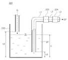
도 4를 참조하면, 본 발명의 일 실시예에 따른 증착 시스템에서, 가스 공급부(220)는 서브 탱크(222)와 함께, 액체 유량 컨트롤러(223) 및 기화기(224)를 포함할 수 있다. 액체 유량 컨트롤러(223)는 기화기(224)로 공급되는 액체 전구체(LP)의 양을 조절할 수 있다. 기화기는 액체 유량 컨트롤러(223)로부터 공급된 액체 전구체(LP)를 기화시켜 기체 전구체(GP) 상태로 반응 챔버에 공급할 수 있다.Referring to FIG. 4 , in the deposition system according to an embodiment of the present invention, the
일례로, 서브 탱크(222)에는 액체 전구체(LP)가 소정의 높이(H)까지 채워질 수 있다. 액체 전구체(LP)를 액체 유량 컨트롤러(223)로 공급하기 위해, 서브 탱크(222)의 제2 높이(h2)에는 운반 가스(G)가 분사될 수 있다. 일례로, 제2 높이(h2)는 액체 전구체(LP)가 채워진 소정의 높이(H)보다 높을 수 있다. 다시 말해, 운반 가스(G)는 액체 전구체(LP)의 표면에 분사될 수 있다.For example, the
한편, 운반 가스(G)의 분사에 의해 액체 전구체(LP)의 일부는 제1 배관(L1)을 따라 액체 유량 컨트롤러(223)로 공급될 수 있다. 일례로, 제1 배관(L1)의 입구는 액체 전구체(LP)가 채워진 소정의 높이(H)보다 낮은 제3 높이(h3)에 배치될 수 있다. 다만, 이는 일 실시예에 불과할 뿐 한정되지 않을 수 있다.Meanwhile, a portion of the liquid precursor LP may be supplied to the
액체 전구체(LP)는 액체 유량 컨트롤러(223)에 의해 조절된 양만큼 제2 배관(L2)을 따라 기화기(224)로 공급될 수 있다. 한편, 기화기(224)를 이용하여 기체 상태로 상변화한 기체 전구체(GP)는 제3 배관(L3)을 따라 반응 챔버로 공급될 수 있다. 다시 말해, 제1 배관(L1) 및 제2 배관(L2)을 지나는 전구체는 액체 전구체(LP)일 수 있고, 제3 배관(L3)을 지나는 전구체는 기체 전구체(GP)일 수 있다.The liquid precursor LP may be supplied to the
본 발명의 일 실시예에 따른 증착 시스템에서, 기화기(224)를 이용하는 액체 전구체(LP)는 낮은 증기압을 갖는 물질일 수 있다. 다만, 이는 일 실시예에 불과할 뿐 한정되지 않고, 증기압의 크기와 무관하게 기체 전구체(GP)의 공급량을 증가시키기 위한 목적으로 기화기(224)를 이용할 수도 있다.In the deposition system according to an embodiment of the present invention, the liquid precursor LP using the
도 3, 4를 참조하면, 본 발명의 일 실시예에 따른 증착 시스템에서, 전구체를 기화시키기 위한 버블러 또는 기화기는 다른 구성들과 연관되어 전체적인 하나의 시스템으로 동작할 수 있다. 다만, 이는 일 실시예에 불과할 뿐 한정되지 않고, 다른 구성들의 동작과 무관하게 별개의 시스템에 의해 동작할 수도 있다. 일례로, 버블러 또는 기화기는 별도의 가스 공급 시스템에 의해 동작할 수 있다.Referring to FIGS. 3 and 4 , in the deposition system according to an embodiment of the present invention, a bubbler or a vaporizer for vaporizing a precursor may operate as a whole system in association with other components. However, this is only an embodiment and is not limited thereto, and may be operated by a separate system regardless of the operation of other components. In one example, the bubbler or vaporizer may be operated by a separate gas supply system.
도 5는 본 발명의 일 실시예에 따른 증착 시스템에서, 자동 충진 시스템의 동작을 설명하기 위한 개략적인 흐름도이다.5 is a schematic flowchart illustrating an operation of an automatic filling system in a deposition system according to an embodiment of the present invention.
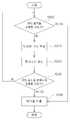
도 5를 참조하면, 본 발명의 일 실시예에 따른 증착 시스템은 자동 충진 시스템이 적용됨으로써 메인 탱크에서 서브 탱크로 액체 전구체가 충진될 수 있다. 일례로, 자동 충진 시스템은 서브 탱크에 채워진 액체 전구체가 소정의 양 이상인지 여부를 확인할 수 있다(S100). 상기 소정의 양은 다음 번 공정을 진행하기 위해 필요한 액체 전구체의 양일 수 있다. 다만, 이는 일 실시예에 불과할 뿐 한정되지 않고, 필요에 따라 서브 탱크에는 공정 상 여유분 이상의 액체 전구체가 더 채워질 수도 있다.Referring to FIG. 5 , in the deposition system according to an embodiment of the present invention, a liquid precursor may be filled from a main tank to a sub tank by applying an automatic filling system. As an example, the automatic filling system may check whether the liquid precursor filled in the sub-tank is equal to or greater than a predetermined amount ( S100 ). The predetermined amount may be an amount of the liquid precursor required to proceed with the next process. However, this is only one embodiment and is not limited thereto, and if necessary, the sub tank may be further filled with a liquid precursor greater than or equal to a surplus during the process.
서브 탱크에 채워진 액체 전구체가 소정의 양보다 적은 경우, 자동 충진 시스템이 동작하여 메인 탱크에 저장된 액체 전구체를 서브 탱크에 충진할 수 있다(S110). 일례로, 메인 탱크와 서브 탱크 사이에는 진공 펌프가 배치될 수 있고, 액체 전구체는 상기 진공 펌프로 형성된 음압을 이용하여 자동으로 충진이 이루어질 수 있다. 한편, 서브 탱크에 채워진 액체 전구체가 소정의 양 이상인 경우, 앞서 서술한 증착 공정이 진행될 수 있다(S120).When the liquid precursor filled in the sub tank is less than a predetermined amount, the automatic filling system may operate to fill the sub tank with the liquid precursor stored in the main tank ( S110 ). For example, a vacuum pump may be disposed between the main tank and the sub tank, and the liquid precursor may be automatically filled using a negative pressure formed by the vacuum pump. Meanwhile, when the amount of the liquid precursor filled in the sub tank is greater than or equal to a predetermined amount, the deposition process described above may be performed ( S120 ).
증착 공정이 완료된 후(S130), 증착 공정을 계속 진행할 것인지 여부를 확인하고(S140), 증착 공정을 계속 진행하고자 하는 경우에는 S100의 단계부터 다시 반복될 수 있다.After the deposition process is completed (S130), it is checked whether to continue the deposition process (S140), and if the deposition process is to be continued, the step S100 may be repeated again.
본 발명의 일 실시예에 따른 증착 시스템에 적용되는 자동 충진 시스템은, 캐니스터를 지속적으로 교체하는 대신 서브 탱크에 액체 전구체를 충진하며 증착 공정을 진행할 수 있다. 이를 통해 캐니스터를 교체하기 위한 설비 정지 기간을 공정 기간으로 활용함으로써 공정 효율을 개선할 수 있다.The automatic filling system applied to the deposition system according to an embodiment of the present invention may perform the deposition process while filling the sub-tank with a liquid precursor instead of continuously replacing the canister. In this way, the process efficiency can be improved by utilizing the shutdown period for replacing the canister as the process period.
도 6은 본 발명의 일 실시예에 따른 증착 시스템에서, 배기물의 배출 과정을 설명하기 위한 개략적인 도면이다.6 is a schematic diagram for explaining a process of discharging exhaust in a deposition system according to an embodiment of the present invention.
도 6을 참조하면, 본 발명의 일 실시예에 따른 증착 시스템에서, 증착 공정에서 생성되는 배기물(WP)들은 반응 챔버의 배기단을 통해 배기부(30)로 배출될 수 있다. 일례로, 배기부(30)는 배기물(WP)의 화학적 구조를 변화시키는 플라즈마 전처리 시스템(PPS)이 적용되는 처리 공정 챔버(31), 펌프(32), 및 스크러버(33)를 포함할 수 있다.Referring to FIG. 6 , in the deposition system according to an embodiment of the present invention, exhaust gases WP generated in the deposition process may be discharged to the
본 발명의 일 실시예에 따른 증착 시스템에서, 플라즈마 전처리 시스템은 반응 챔버에서 배출된 배기물(WP)을 분해 및/또는 치환하여 배출을 용이하게 할 수 있다. 일례로, 배기물(WP)은 처리 공정 챔버(31)에서 플라즈마 전처리 시스템이 적용될 수 있다. 다만, 플라즈마 전처리 시스템은 본 발명의 일 실시예에 따른 증착 시스템에 적용되는 것으로 한정되지 않고, 증착 공정뿐만 아니라 배기물(WP)을 배출하는 다른 공정에도 적용될 수 있다. 일례로, 플라즈마 전처리 시스템은 애싱(ashing), 에칭(etching), 세정(cleaning), 어닐링(annealing) 등의 공정에도 적용될 수 있다.In the deposition system according to an embodiment of the present invention, the plasma pretreatment system may facilitate the discharge by decomposing and/or replacing the exhaust WP discharged from the reaction chamber. For example, a plasma pretreatment system may be applied to the exhaust WP in the
한편, 플라즈마 전처리 시스템이 적용되기 전의 배기물(WP)은 미처 반응하지 못한 전구체 및/또는 반응하고 남은 부산물일 수 있다. 일례로, 배기물(WP)은 지르코니아 등과 같이 상대적으로 복잡한 구조를 갖는 물질일 수 있다. 이에 따라, 플라즈마 전처리 시스템의 적용없이 그대로 배출되는 경우, 펌프(32)에 무리를 주거나, 배기물(WP)이 배관에 축적되는 등의 문제로 인해 펌프(32)의 수명이 줄어들 수 있다.On the other hand, the exhaust WP before the plasma pretreatment system is applied may be an unreacted precursor and/or a by-product remaining after reacting. For example, the exhaust WP may be a material having a relatively complex structure, such as zirconia. Accordingly, when the plasma is discharged without application of the pretreatment system, the life of the
처리 공정 챔버(31)에는 플라즈마 전처리 시스템이 적용될 수 있다. 플라즈마 전처리 시스템은 반응성 가스(RG)를 공급하고, 플라즈마 방전을 유도하는 과정을 포함할 수 있다. 일례로, 반응성 가스(RG)는 O2일 수 있다. 플라즈마 방전에 의해 분해 성능이 높아진 배기물들은 전하를 갖는 이온으로 분해될 수 있다. 일례로, 플라즈마 전처리 시스템이 적용된 배기물들은 N3-, O2-, H+, Mx+, C, e-(전자) 등을 포함할 수 있다. 다만, 이는 일 실시예에 불과할 뿐 한정되지 않고, 플라즈마 전처리 시스템에 의한 동작 및 분해된 배기물들은 실시예들에 따라 상이할 수도 있다.A plasma pretreatment system may be applied to the
한편, 펌프(32)로 이동한 이온 상태의 배기물들은 재결합하여 새로운 물질을 형성할 수 있다. 일례로, 펌프(32)에는 MOX, NO2, H2O, CO2, 등이 포함될 수 있다. 다만, 이는 일 실시예에 불과할 뿐 한정되지 않고, 그 외에 다양한 물질들을 포함할 수도 있다. 일례로, 펌프(32)에는 재결합되지 않은 H+(양이온)가 포함되어 있을 수도 있다.On the other hand, the exhausts in the ionic state that have moved to the
스크러버(33)는 남아 있는 배기물들 중 적어도 일부를 용해시켜 배출할 수 있다. 한편, 플라즈마 전처리 시스템이 적용된 배기물들은 초기 배기물(WP)과 비교하여 상대적으로 간단한 구조를 가지는 물질로 분해 및/또는 치환되므로, 스크러버(33)의 효율은 증가할 수 있다. 일례로, 스크러버(33)를 통해 외부로 배출되는 배기물은 MOX, NO2, H2O, CO2, H2 등의 형태일 수 있다. 다만, 이는 일 실시예에 불과할 뿐 한정되지 않고, 그 외에 다양한 물질들을 포함할 수도 있다.The
도 7은 본 발명의 일 실시예에 따른 증착 시스템에서, 플라즈마 전처리 시스템의 동작을 설명하기 위한 개략적인 흐름도이다.7 is a schematic flowchart illustrating an operation of a plasma pretreatment system in a deposition system according to an embodiment of the present invention.
도 7을 참조하면, 플라즈마 전처리 시스템 동작은 모든 공정 과정에서 항상 진행되는 것은 아닐 수 있다. 따라서, 본 발명의 일 실시예에 따른 증착 시스템은 플라즈마 전처리 시스템의 동작 여부를 결정하는 단계(S200)를 거칠 수 있다. 플라즈마 전처리 시스템은 공정 도중 및/또는 공정과 공정 사이에 동작할 수 있다. 플라즈마 전처리 시스템이 동작하지 않는 경우, 반응 챔버에서 배출된 배기물은 펌프와 스크러버를 거쳐 외부로 배출될 수 있다.Referring to FIG. 7 , the operation of the plasma pretreatment system may not always be performed in all processes. Accordingly, the deposition system according to an embodiment of the present invention may go through the step S200 of determining whether the plasma pretreatment system operates. The plasma pretreatment system may operate during and/or between processes. When the plasma pretreatment system does not operate, the exhaust exhaust from the reaction chamber may be discharged to the outside through a pump and a scrubber.
플라즈마 전처리 시스템이 동작하는 경우, 처리 공정 챔버에는 반응성 가스가 투입될 수 있다(S210). 일례로, 앞서 서술한 바와 같이 반응성 가스는 O2일 수 있다. 반응성 가스는 반응 챔버에서 배출된 배기물과 반응하여 분해될 수 있다.When the plasma pretreatment system is operating, a reactive gas may be introduced into the processing chamber ( S210 ). For example, as described above, the reactive gas may beO 2 . The reactive gas may be decomposed by reacting with the exhaust exhausted from the reaction chamber.
다만, 완전히 분해되지 않은 파우더 형태의 배기물은 펌프에 축적되어 펌프의 수명을 단축시킬 수 있는 바, 플라즈마 방전을 일으켜 분해 성능을 향상시킬 수 있다(S220). 일례로, 플라즈마 방전은 RF 플라즈마 방전 형태로 발생될 수 있다. 다만 이는 일 실시예에 불과할 뿐 한정되지 않고, 실시예들에 따라 DC 글로우 방전 등의 형태로 발생될 수도 있다.However, the exhaust in the form of powder that is not completely decomposed may accumulate in the pump and shorten the life of the pump, thereby generating plasma discharge to improve the decomposition performance ( S220 ). For example, the plasma discharge may be generated in the form of an RF plasma discharge. However, this is only an example, and is not limited thereto, and may be generated in the form of DC glow discharge or the like according to embodiments.
본 발명의 일 실시예에 따른 증착 시스템에서, 플라즈마 전처리 시스템은 실시예에 따라 복수 회 반복되어 동작할 수도 있다. 따라서, 플라즈마 전처리 시스템을 반복하여 동작시킬 것인지 여부를 결정하는 단계(S230)를 거칠 수 있다. 이에 따라, S210 및 S220의 단계는 복수 회 반복될 수도 있다. 상기 단계들에 의해 분해 성능이 향상된 배기물은 펌프 및 스크러버를 통해 배출될 수 있다(S240). 다만, 전술한 바와 같이 이는 일 실시예에 불과할 뿐 한정되지 않고, 배기부의 구성 및 각 구성들의 배치는 실시예에 따라 달라질 수 있다.In the deposition system according to the embodiment of the present invention, the plasma pretreatment system may be repeatedly operated a plurality of times depending on the embodiment. Accordingly, the step ( S230 ) of determining whether to repeatedly operate the plasma pretreatment system may be performed. Accordingly, steps S210 and S220 may be repeated a plurality of times. The exhaust with improved decomposition performance by the above steps may be discharged through a pump and a scrubber (S240). However, as described above, this is only one embodiment and is not limited thereto, and the configuration of the exhaust unit and the arrangement of each configuration may vary according to the embodiment.
본 발명의 일 실시예에 따른 증착 시스템에 적용되는 플라즈마 전처리 시스템은, 분해 성능이 향상된 배기물을 배출할 수 있도록 동작할 수 있다. 이에 따라, 펌프에 축적되는 배기물을 감소시켜 펌프의 수명을 연장시킬 수 있다. 또한, 스크러버의 효율을 증가시킴으로써 배기 효율을 개선할 수 있다.The plasma pretreatment system applied to the deposition system according to an embodiment of the present invention may operate to discharge the exhaust with improved decomposition performance. Accordingly, it is possible to extend the life of the pump by reducing the exhaust gas accumulated in the pump. In addition, the exhaust efficiency can be improved by increasing the efficiency of the scrubber.
도 8 내지 도 10은 본 발명의 일 실시예에 따른 증착 시스템의 개략적인 블록도이다.8 to 10 are schematic block diagrams of a deposition system according to an embodiment of the present invention.
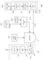
도 8을 참조하면, 본 발명의 일 실시예에 따른 증착 시스템(300)은 증착하려는 박막이 2원계 물질 또는 3원계 물질로 이루어진 경우의 증착 시스템일 수 있다. 일례로, 증착 시스템(300)은 도 1의 증착 시스템(1)에 도시된 각 구성들에 대응되는 구성들을 포함할 수 있다. 한편, 가스 공급부(20)에 대응되는 제1 가스 공급부(320a)와 함께, 제2 가스 공급부(320b)를 더 포함할 수 있다.Referring to FIG. 8 , the
증착하려는 박막의 일 성분인 제1 전구체는 제1 메인 탱크(340a)로부터 제1 자동 충진 시스템(ARS_a)에 의해 제1 가스 공급부(320a)에 충진될 수 있다. 제1 가스 공급부(320a)는 반응 챔버(310)에 기체 상태의 제1 전구체를 공급할 수 있고, 제2 가스 공급부(320b)는 반응 챔버(310)에 제1 전구체와 다른 제2 전구체를 기체 상태로 공급할 수 있다.The first precursor, which is a component of the thin film to be deposited, may be filled in the first
본 발명의 일 실시예에 따른 증착 시스템(300)에서, 제2 가스 공급부(320b)는 제1 가스 공급부(320a)에 대응되는 구성들을 포함할 수 있다. 일례로, 제2 가스 공급부(320b)는 제2 서브 탱크(322b), 제2 액체 유량 컨트롤러(323b), 제2 기화기(324b), 및 제2 필터(325b)를 포함할 수 있다. 제2 서브 탱크(322b)는 제2 메인 탱크(340b)로부터 제2 자동 충진 시스템(ARS_b)에 의해 충진된 제2 전구체를 저장할 수 있다.In the
한편, 제1 전구체 및 제2 전구체는 반응 챔버(310)에서 반응물 공급부(350)로부터 공급된 반응물(reactant)과 반응하여 기판 상에 박막을 형성할 수 있다. 증착 공정에 의해 배출되는 배기물들은 도 6에 도시된 플라즈마 전처리 시스템이 적용된 후 외부로 배출될 수 있다. 그 외의 구성들의 특징 및 동작은 도 1에 도시된 증착 시스템(1)과 동일할 수 있다. 다만, 이는 일 실시예에 불과할 뿐 한정되지 않고, 제1 전구체와 제2 전구체의 물성 차이에 따라 제1 가스 공급부(320a)와 제2 가스 공급부(320b)의 구성은 서로 다른 특징을 가질 수도 있다.Meanwhile, the first precursor and the second precursor may react with a reactant supplied from the
도 9를 참조하면, 본 발명의 일 실시예에 따른 증착 시스템(400)은 증착하려는 박막이 2원계 물질 또는 3원계 물질로 이루어진 경우의 증착 시스템일 수 있다. 일례로, 도 1의 증착 시스템(1)에 도시된 가스 공급부(20)에 대응되는 제1 가스 공급부(420a)와 함께, 제2 가스 공급부(420b)를 더 포함할 수 있다.Referring to FIG. 9 , a
증착하려는 박막의 일 성분인 제1 전구체는 제1 메인 탱크(440a)로부터 제1 자동 충진 시스템(ARS_a)에 의해 제1 가스 공급부(420a)에 충진될 수 있다. 제1 가스 공급부(420a)는 반응 챔버(410)에 기체 상태의 제1 전구체를 공급할 수 있다. 제1 전구체와 다른 제2 전구체는 제2 메인 탱크(440b)로부터 제2 자동 충진 시스템(ARS_b)에 의해 제2 서브 탱크(422b)에 충진될 수 있다. 제2 가스 공급부(420b)는 반응 챔버(410)에 제2 전구체를 기체 상태로 공급할 수 있다.The first precursor, which is a component of the thin film to be deposited, may be filled in the first
한편, 본 발명의 일 실시예에 따른 증착 시스템(400)에 포함된 제2 가스 공급부(420b)는, 도 8에 도시된 증착 시스템(300)에 포함된 제2 가스 공급부(320b)와는 달리 버블러를 이용하여 제2 전구체를 기화시킬 수 있다. 일례로, 운반 가스 공급부(421b) 제2 서브 탱크(422b)에 운반 가스(carrier gas)를 공급할 수 있다. 일례로, 운반 가스는 반응성이 낮은 N2 등의 기체일 수 있다. 제2 서브 탱크(422b)에 저장되어 있던 액체 상태의 제2 전구체는 베이킹(baking) 및/또는 버블링(bubbling) 방식에 의해 기화되어 반응 챔버(410)으로 공급될 수 있다.Meanwhile, the second
한편, 제1 전구체 및 제2 전구체는 반응 챔버(410)에서 반응물 공급부(450)로부터 공급된 반응물과 반응하여 기판 상에 박막을 형성할 수 있다. 증착 공정에 의해 배출되는 배기물들은 도 6에 도시된 플라즈마 전처리 시스템이 적용된 후 외부로 배출될 수 있다. 그 외의 구성들의 특징 및 동작은 도 1에 도시된 증착 시스템(1)과 동일할 수 있다. 다만, 이는 일 실시예에 불과할 뿐 한정되지 않고, 제1 전구체와 제2 전구체의 물성 차이에 따라 제1 가스 공급부(420a)와 제2 가스 공급부(420b)의 구성은 서로 다른 특징을 가질 수도 있다.Meanwhile, the first precursor and the second precursor may react with the reactant supplied from the
도 10을 참조하면, 본 발명의 일 실시예에 따른 증착 시스템(500)은 도 1의 증착 시스템(1)에 도시된 가스 공급부(20)에 대응되는 제1 가스 공급부(520a)와 함께, 복수의 가스 공급부들(520b, 520c, ..., 520n)을 더 포함할 수 있다. 일례로, 도 10에 도시된 증착 시스템(500)의 적어도 일부는 도 8에 도시된 증착 시스템(300) 및/또는 도 9에 도시된 증착 시스템(400)과 동일할 수 있다.Referring to FIG. 10 , a
제1 가스 공급부(520a)는 반응 챔버(510)에 기체 상태의 제1 전구체를 공급할 수 있다. 일례로, 제n 가스 공급부는 반응 챔버(510)에 기체 상태의 제n 전구체를 공급할 수 있다.The first
가스 공급부들(520a, 520b, ..., 520n) 및 반응물 공급부(550)의 개수는 기판 상에 증착되는 박막의 성분에 의해 결정될 수 있다. 일례로, 2원계 물질로 구성되는 박막의 경우 1개의 가스 공급부(520a) 및 반응물 공급부(550)를 포함하는 증착 시스템에 의해 증착 공정이 진행될 수 있다. 또한, 3원계 물질로 구성되는 박막의 경우 2개의 가스 공급부(520a, 520b) 및 반응물 공급부(550)를 포함하는 증착 시스템에 의해 증착 공정이 진행될 수 있다. 다만 이는 일 실시예에 불과할 뿐 한정되지 않고, 증착 공정 방법에 따라 박막의 구성 원소의 개수와 가스 공급부(520a, 520b, ..., 520n) 및 반응물 공급부(550)의 개수는 다를 수도 있다.The number of the
한편, 복수의 가스 공급부들(520a, 520b, ..., 520n)은 각각 독립적인 구성들을 포함할 수 있다. 일례로, 복수의 가스 공급부들(520a, 520b, ..., 520n)은 모두 도 1에 도시된 증착 시스템과 유사하게 기화기를 포함하는 가스 공급부일 수 있다. 다만, 이에 한정되지 않고, 복수의 가스 공급부들(520a, 520b, ..., 520n)중 적어도 일부는 버블러를 포함하는 가스 공급부일 수도 있다.Meanwhile, the plurality of
본 발명의 일 실시예에 따른 증착 시스템에서, n개의 가스 공급부들(520a, 520b, ..., 520n)로부터 각각 공급되는 제1 전구체 내지 제n 전구체는 반응물 공급부(550)로부터 공급된 반응물과 반응하여 기판 상에 박막을 형성할 수 있다.In the deposition system according to an embodiment of the present invention, the first to nth precursors respectively supplied from the n
증착 공정에 의해 배출되는 배기물들은 도 6에 도시된 플라즈마 전처리 시스템이 적용된 후 외부로 배출될 수 있다. 그 외의 구성들의 특징 및 동작은 도 1에 도시된 증착 시스템(1)과 동일할 수 있다. 다만, 이는 일 실시예에 불과할 뿐 한정되지 않고, 제1 전구체 내지 제n 전구체들의 물성 차이에 따라 제1 가스 공급부(520a) 내지 제n 가스 공급부(520n)의 구성은 서로 다른 특징을 가질 수도 있다.Exhausts discharged by the deposition process may be discharged to the outside after the plasma pretreatment system shown in FIG. 6 is applied. Features and operations of other components may be the same as those of the
본 발명은 상술한 실시예 및 첨부된 도면에 의해 한정되는 것이 아니며 첨부된 청구범위에 의해 한정하고자 한다. 따라서, 청구범위에 기재된 본 발명의 기술적 사상을 벗어나지 않는 범위 내에서 당 기술분야의 통상의 지식을 가진 자에 의해 다양한 형태의 치환, 변형 및 변경이 가능할 것이며, 이 또한 본 발명의 범위에 속한다고 할 것이다.The present invention is not limited by the above-described embodiments and the accompanying drawings, but is intended to be limited by the appended claims. Therefore, various types of substitution, modification and change will be possible by those skilled in the art within the scope not departing from the technical spirit of the present invention described in the claims, and it is also said that it falls within the scope of the present invention. something to do.
1: 증착 시스템10: 반응 챔버
20: 가스 공급부421b: 운반 가스 공급부
22: 서브 탱크23: 액체 유량 컨트롤러
24: 기화기25: 필터
30: 배기부31: 처리 공정 챔버
32: 펌프33: 스크러버
40: 메인 탱크50: 반응물 공급부
ARS: 자동 충진 시스템PPS: 플라즈마 전처리 시스템1: deposition system 10: reaction chamber
20:
22: sub tank 23: liquid flow controller
24: carburetor 25: filter
30: exhaust 31: treatment process chamber
32: pump 33: scrubber
40: main tank 50: reactant supply
ARS: Automatic filling system PPS: Plasma pretreatment system
Claims (20)
Translated fromKorean제1 메인 탱크에 저장된 액체 상태의 제1 전구체를 상기 반응 챔버에 기체 상태로 공급하는 제1 가스 공급부;
상기 반응 챔버에 상기 제1 전구체와 반응하는 반응물을 공급하는 반응물 공급부; 및
상기 반응 챔버에서 생성되는 배기물을 배출하는 배기부; 를 포함하고,
상기 제1 가스 공급부는 순차적으로 연결되는 제1 서브 탱크, 제1 액체 유량 컨트롤러, 및 제1 기화기를 포함하고,
제1 자동 충진 시스템에 의해 상기 제1 서브 탱크에 충진된 상기 제1 전구체는, 상기 제1 서브 탱크, 상기 제1 액체 유량 컨트롤러, 및 상기 제1 기화기를 순차적으로 경유하여 상기 반응 챔버로 공급되며,
상기 제1 자동 충진 시스템은 상기 제1 메인 탱크와 상기 제1 가스 공급부 사이의 배관에 음압을 형성하고, 상기 제1 메인 탱크에 저장된 액체 상태의 상기 제1 전구체를 상기 제1 서브 탱크에 주기적으로 충진하여 상기 제1 전구체가 상기 반응 챔버에 공급될 수 있는 상태를 유지하도록 동작하고,
상기 배기부는 상기 배기물의 분해 성능을 증가시키는 플라즈마 전처리 시스템이 적용되는 처리 공정 챔버, 펌프, 및 스크러버를 포함하는 증착 시스템.
reaction chamber;
a first gas supply unit supplying a first precursor in a liquid state stored in a first main tank to the reaction chamber in a gaseous state;
a reactant supply unit supplying a reactant reacting with the first precursor to the reaction chamber; and
an exhaust unit for discharging exhaust gas generated in the reaction chamber; including,
The first gas supply unit includes a first sub tank, a first liquid flow controller, and a first vaporizer that are sequentially connected,
The first precursor filled in the first sub-tank by a first automatic filling system is sequentially supplied to the reaction chamber via the first sub-tank, the first liquid flow controller, and the first vaporizer, ,
The first automatic filling system forms a negative pressure in a pipe between the first main tank and the first gas supply unit, and periodically supplies the first precursor in a liquid state stored in the first main tank to the first sub tank. operates to maintain a state in which the first precursor can be supplied to the reaction chamber by filling,
The exhaust unit includes a processing chamber to which a plasma pretreatment system for increasing the decomposition performance of the exhaust is applied, a pump, and a scrubber.
상기 제1 액체 유량 컨트롤러는 상기 제1 전구체를 단위 시간당 일정한 양으로 상기 제1 기화기에 공급하는 증착 시스템.
According to claim 1,
The first liquid flow controller supplies the first precursor to the first vaporizer in a constant amount per unit time.
제2 메인 탱크에 저장된 액체 상태의 제2 전구체를 상기 반응 챔버에 기체 상태로 공급하는 제2 가스 공급부; 를 더 포함하고,
상기 제2 가스 공급부는 상기 제2 전구체를 저장하는 제2 서브 탱크를 포함하며,
상기 제2 전구체는 상기 제1 전구체와 다른 원소로 구성되는 증착 시스템.
According to claim 1,
a second gas supply unit supplying a second precursor in a liquid state stored in a second main tank to the reaction chamber in a gaseous state; further comprising,
The second gas supply unit includes a second sub tank for storing the second precursor,
wherein the second precursor is composed of an element different from that of the first precursor.
상기 제2 가스 공급부는 상기 제1 가스 공급부와 다른 별도의 경로를 통해 상기 제2 전구체를 상기 반응 챔버로 공급하는 증착 시스템.
4. The method of claim 3,
The second gas supply unit supplies the second precursor to the reaction chamber through a separate path different from that of the first gas supply unit.
상기 제2 가스 공급부에는 상기 제1 자동 충진 시스템과 별개로 동작하는 제2 자동 충진 시스템이 적용되고,
상기 제2 자동 충진 시스템은 상기 제2 메인 탱크에 저장된 액체 상태의 상기 제2 전구체를 상기 제2 서브 탱크에 주기적으로 충진하도록 동작하는 증착 시스템.
4. The method of claim 3,
A second automatic filling system operating separately from the first automatic filling system is applied to the second gas supply unit,
and the second automatic filling system operates to periodically fill the second sub-tank with the second precursor in a liquid state stored in the second main tank.
상기 제2 가스 공급부는 버블러 또는 기화기 중 어느 하나의 기화 장치를 더 포함하고,
상기 기화 장치는 상기 제2 전구체의 증기압 및 상기 제2 전구체의 필요 공급량에 따라 결정되며,
상기 결정된 기화 장치에 의해 기화된 상기 제2 전구체는 상기 반응 챔버에 공급되는 증착 시스템.
4. The method of claim 3,
The second gas supply unit further comprises a vaporization device of any one of a bubbler or a vaporizer,
The vaporization device is determined according to the vapor pressure of the second precursor and the required supply amount of the second precursor,
The second precursor vaporized by the determined vaporization device is supplied to the reaction chamber.
상기 제2 가스 공급부는 상기 제2 서브 탱크와 상기 반응 챔버 사이에 순차적으로 연결되는 제2 액체 유량 컨트롤러, 및 제2 기화기를 더 포함하고,
상기 제2 액체 유량 컨트롤러는 상기 제2 전구체의 유량을 조절하여 상기 제2 기화기로 공급하고,
상기 제2 기화기는 상기 제2 전구체를 기화시켜 상기 반응 챔버에 공급하는 증착 시스템.
4. The method of claim 3,
The second gas supply unit further includes a second liquid flow controller sequentially connected between the second sub-tank and the reaction chamber, and a second vaporizer,
The second liquid flow controller controls the flow rate of the second precursor and supplies it to the second vaporizer,
The second vaporizer vaporizes the second precursor and supplies it to the reaction chamber.
상기 제2 가스 공급부는 운반 가스 공급부 및 버블러를 더 포함하고,
상기 운반 가스 공급부는 운반 가스를 상기 제2 서브 탱크에 주입하고,
상기 버블러는 상기 운반 가스를 이용하여 버블링(bubbling) 현상을 발생시키며,
상기 버블링 현상에 의해 기화된 상기 제2 전구체는 상기 반응 챔버에 공급되는 증착 시스템.
4. The method of claim 3,
The second gas supply unit further comprises a carrier gas supply unit and a bubbler,
The carrier gas supply unit injects a carrier gas into the second sub-tank,
The bubbler generates a bubbling phenomenon using the carrier gas,
The second precursor vaporized by the bubbling phenomenon is supplied to the reaction chamber.
상기 제2 전구체의 증기압은 100℃에서 1Torr 이상인 증착 시스템.
9. The method of claim 8,
The vapor pressure of the second precursor is 1 Torr or more at 100 ℃ deposition system.
상기 제2 가스 공급부는 운반 가스 공급부를 더 포함하고,
상기 운반 가스 공급부는 운반 가스를 상기 제2 서브 탱크에 주입하며,
베이킹(baking) 방식으로 기화된 상기 제2 전구체는 상기 반응 챔버에 공급되는 증착 시스템.
4. The method of claim 3,
The second gas supply unit further comprises a carrier gas supply,
The carrier gas supply unit injects the carrier gas into the second sub-tank,
The second precursor vaporized in a baking method is supplied to the reaction chamber.
상기 제1 가스 공급부는 상기 제1 기화기와 상기 반응 챔버 사이에 배치되는 필터; 를 더 포함하는 증착 시스템.
According to claim 1,
The first gas supply unit may include a filter disposed between the first vaporizer and the reaction chamber; A deposition system further comprising a.
상기 반응 챔버는 배치(batch), 세미 배치(semi-batch), 또는 싱글(single) 타입인 것을 특징으로 하는 증착 시스템.
According to claim 1,
The deposition system, characterized in that the reaction chamber is a batch (batch), semi-batch (semi-batch), or single (single) type.
상기 플라즈마 전처리 시스템은 상기 배기물에 반응성 가스를 공급한 뒤, 플라즈마 방전을 유도함으로써 동작하는 증착 시스템.
According to claim 1,
The plasma pretreatment system operates by supplying a reactive gas to the exhaust and then inducing a plasma discharge.
상기 반응 챔버에 적어도 하나의 전구체를 기체 상태로 각각 공급하는 적어도 하나의 가스 공급부;
상기 반응 챔버에 상기 전구체와 반응하는 반응물을 공급하는 반응물 공급부; 및
상기 반응 챔버에서 생성되는 배기물을 배출하는 배기부; 를 포함하고,
상기 적어도 하나의 가스 공급부는 각각,
메인 탱크에 연결된 배관에 음압을 형성하여 상기 전구체를 주기적으로 충진함으로써 상기 전구체가 상기 반응 챔버에 공급될 수 있는 상태를 유지시키는 자동 충진 시스템이 적용되는 서브 탱크;
상기 전구체를 기체 상태로 상기 반응 챔버에 공급하기 위한 기화기, 및
상기 기화기로 공급되는 상기 전구체의 양을 조절하는 액체 유량 컨트롤러; 를 포함하며,
상기 배기부는 처리 공정 챔버, 펌프, 및 스크러버를 포함하고,
상기 처리 공정 챔버는 상기 배기물의 화학적 구조를 변화시키는 플라즈마 전처리 시스템을 적용한 뒤, 상기 펌프를 통해 상기 배기물을 배출하는 증착 시스템.
reaction chamber;
at least one gas supply unit for respectively supplying at least one precursor in a gaseous state to the reaction chamber;
a reactant supply unit supplying a reactant reacting with the precursor to the reaction chamber; and
an exhaust unit for discharging exhaust gas generated in the reaction chamber; including,
Each of the at least one gas supply unit,
a sub tank to which an automatic filling system is applied to maintain a state in which the precursor can be supplied to the reaction chamber by periodically filling the precursor by forming a negative pressure in a pipe connected to the main tank;
a vaporizer for supplying the precursor in a gaseous state to the reaction chamber; and
a liquid flow controller for controlling the amount of the precursor supplied to the vaporizer; includes,
The exhaust includes a treatment process chamber, a pump, and a scrubber;
The processing chamber is configured to apply a plasma pretreatment system for changing the chemical structure of the exhaust, and then discharge the exhaust through the pump.
상기 자동 충진 시스템은 상기 전구체를 사용한 제1 공정과 상기 제1 공정 이후에 진행되는 제2 공정 사이에 상기 전구체를 상기 서브 탱크에 자동으로 충진하는 것을 특징으로 하는 증착 시스템.
15. The method of claim 14,
The automatic filling system automatically fills the sub-tank with the precursor between a first process using the precursor and a second process performed after the first process.
상기 플라즈마 전처리 시스템은 상기 반응 챔버에서의 공정과 별개로, 필요에 따라 선택적으로 동작하도록 제어되는 증착 시스템.
15. The method of claim 14,
wherein the plasma pretreatment system is controlled to operate selectively as needed, independent of the process in the reaction chamber.
상기 서브 탱크에 저장된 상기 공정 물질을 기체 상태로 반응 챔버에 공급하는 가스 공급 시스템; 및
플라즈마 방전을 유도하여 상기 반응 챔버에서 배출된 배기물의 화학적 구조를 변화시키도록 동작하는 플라즈마 전처리 시스템; 을 포함하고,
상기 가스 공급 시스템은 상기 서브 탱크와 상기 반응 챔버 사이에 순차적으로 연결된 액체 유량 컨트롤러 및 기화기를 동작시키며,
상기 액체 유량 컨트롤러는 상기 기화기에 공급하는 상기 공정 물질의 양을 조절하는 공정 시스템.
At least for generating a negative pressure in a pipe connected to the main tank in which the process material in the liquid state is stored, automatically filling the sub-tank connected to the pipe with the process material in the liquid state, and maintaining the process material stored in the sub-tank at a certain amount or more One automatic filling system;
a gas supply system for supplying the process material stored in the sub tank to the reaction chamber in a gaseous state; and
a plasma pretreatment system operative to induce a plasma discharge to change the chemical structure of the exhaust exhausted from the reaction chamber; including,
The gas supply system operates a liquid flow controller and a vaporizer sequentially connected between the sub-tank and the reaction chamber,
wherein the liquid flow controller regulates the amount of the process material supplied to the vaporizer.
상기 공정 물질은 증착(Deposition) 공정, 에칭(Etching) 공정, 세정(Cleaning) 공정, 애싱(Ashing) 공정, 및 어닐링(Annealing) 공정 중 하나에서 사용되고,
상기 가스 공급 시스템은 기체 상태의 상기 공정 물질을 상기 반응 챔버에 주기적으로 공급하는 공정 시스템.
18. The method of claim 17,
The process material is used in one of a deposition process, an etching process, a cleaning process, an ashing process, and an annealing process,
wherein the gas supply system periodically supplies the process material in a gaseous state to the reaction chamber.
상기 가스 공급 시스템은 복수의 가스 공급부를 포함하고,
상기 복수의 가스 공급부는 복수의 공정 물질들을 각각 상기 반응 챔버에 공급하는 공정 시스템.
18. The method of claim 17,
The gas supply system includes a plurality of gas supply units,
The plurality of gas supply units respectively supply a plurality of process materials to the reaction chamber.
상기 복수의 가스 공급부 중 적어도 일부는 서로 상이한 메커니즘으로 동작하는 공정 시스템.20. The method of claim 19,
At least some of the plurality of gas supply units operate by different mechanisms.
Priority Applications (8)
| Application Number | Priority Date | Filing Date | Title |
|---|---|---|---|
| KR1020200095940AKR102300561B1 (en) | 2020-07-31 | 2020-07-31 | Deposition system and processing system |
| US17/195,900US20220033962A1 (en) | 2020-07-31 | 2021-03-09 | Deposition system and processing system |
| PCT/KR2021/009700WO2022025588A1 (en) | 2020-07-31 | 2021-07-27 | Deposition system and processing system |
| JP2022524666AJP2023536018A (en) | 2020-07-31 | 2021-07-27 | Deposition system and process system |
| DE112021000121.3TDE112021000121T5 (en) | 2020-07-31 | 2021-07-27 | Separation system and process system |
| CN202180006854.9ACN114729448A (en) | 2020-07-31 | 2021-07-27 | Deposition and processing systems |
| TW110127899ATW202206631A (en) | 2020-07-31 | 2021-07-29 | Deposition system and processing system |
| US18/425,048US20240209495A1 (en) | 2020-07-31 | 2024-01-29 | Deposition system and processing system |
Applications Claiming Priority (1)
| Application Number | Priority Date | Filing Date | Title |
|---|---|---|---|
| KR1020200095940AKR102300561B1 (en) | 2020-07-31 | 2020-07-31 | Deposition system and processing system |
Publications (1)
| Publication Number | Publication Date |
|---|---|
| KR102300561B1true KR102300561B1 (en) | 2021-09-13 |
Family
ID=77796547
Family Applications (1)
| Application Number | Title | Priority Date | Filing Date |
|---|---|---|---|
| KR1020200095940AActiveKR102300561B1 (en) | 2020-07-31 | 2020-07-31 | Deposition system and processing system |
Country Status (7)
| Country | Link |
|---|---|
| US (2) | US20220033962A1 (en) |
| JP (1) | JP2023536018A (en) |
| KR (1) | KR102300561B1 (en) |
| CN (1) | CN114729448A (en) |
| DE (1) | DE112021000121T5 (en) |
| TW (1) | TW202206631A (en) |
| WO (1) | WO2022025588A1 (en) |
Cited By (1)
| Publication number | Priority date | Publication date | Assignee | Title |
|---|---|---|---|---|
| WO2025063553A1 (en)* | 2023-09-19 | 2025-03-27 | 주성엔지니어링(주) | Canister and substrate treatment apparatus |
Citations (1)
| Publication number | Priority date | Publication date | Assignee | Title |
|---|---|---|---|---|
| KR20010034781A (en)* | 1998-04-14 | 2001-04-25 | 잭 피. 샐러노 | Film deposition system |
Family Cites Families (13)
| Publication number | Priority date | Publication date | Assignee | Title |
|---|---|---|---|---|
| JP2001185492A (en)* | 1999-12-24 | 2001-07-06 | Hitachi Kokusai Electric Inc | Semiconductor manufacturing equipment |
| JP2002088477A (en)* | 2000-09-12 | 2002-03-27 | Koichi Haga | Method and apparatus for feeding vaporized material, and method and system for organometallic chemical vapor deposition |
| WO2005054537A2 (en)* | 2003-12-01 | 2005-06-16 | Structured Materials Industries, Inc. | System and method for forming multi-component films |
| US7021903B2 (en)* | 2003-12-31 | 2006-04-04 | The Boc Group, Inc. | Fore-line preconditioning for vacuum pumps |
| US20050147749A1 (en)* | 2004-01-05 | 2005-07-07 | Msp Corporation | High-performance vaporizer for liquid-precursor and multi-liquid-precursor vaporization in semiconductor thin film deposition |
| DE502004012396D1 (en)* | 2004-02-20 | 2011-05-26 | Cs Clean Systems Ag | Apparatus and method for refilling a bubble vaporizer |
| KR100855582B1 (en)* | 2007-01-12 | 2008-09-03 | 삼성전자주식회사 | Liquid supply apparatus and method, substrate processing apparatus which has said apparatus, and substrate processing method |
| JP5461786B2 (en)* | 2008-04-01 | 2014-04-02 | 株式会社フジキン | Gas supply device with vaporizer |
| JP5410235B2 (en)* | 2009-10-15 | 2014-02-05 | 小島プレス工業株式会社 | Method and apparatus for forming organic polymer thin film |
| US20110143035A1 (en)* | 2009-12-16 | 2011-06-16 | Byoung Ha Cho | Thin Film Deposition System and Method for Depositing Thin Film |
| KR20110095040A (en)* | 2010-02-18 | 2011-08-24 | 삼성전자주식회사 | Phase change material production apparatus and method |
| KR101536234B1 (en)* | 2013-10-17 | 2015-07-13 | 주식회사 지에스티에스 | Vaporizer |
| CN106029217A (en)* | 2014-03-06 | 2016-10-12 | 应用材料公司 | Plasma Foreline Thermal Reactor System |
- 2020
- 2020-07-31KRKR1020200095940Apatent/KR102300561B1/enactiveActive
- 2021
- 2021-03-09USUS17/195,900patent/US20220033962A1/ennot_activeAbandoned
- 2021-07-27CNCN202180006854.9Apatent/CN114729448A/enactivePending
- 2021-07-27WOPCT/KR2021/009700patent/WO2022025588A1/ennot_activeCeased
- 2021-07-27DEDE112021000121.3Tpatent/DE112021000121T5/enactivePending
- 2021-07-27JPJP2022524666Apatent/JP2023536018A/enactivePending
- 2021-07-29TWTW110127899Apatent/TW202206631A/enunknown
- 2024
- 2024-01-29USUS18/425,048patent/US20240209495A1/enactivePending
Patent Citations (1)
| Publication number | Priority date | Publication date | Assignee | Title |
|---|---|---|---|---|
| KR20010034781A (en)* | 1998-04-14 | 2001-04-25 | 잭 피. 샐러노 | Film deposition system |
Cited By (1)
| Publication number | Priority date | Publication date | Assignee | Title |
|---|---|---|---|---|
| WO2025063553A1 (en)* | 2023-09-19 | 2025-03-27 | 주성엔지니어링(주) | Canister and substrate treatment apparatus |
Also Published As
| Publication number | Publication date |
|---|---|
| US20240209495A1 (en) | 2024-06-27 |
| JP2023536018A (en) | 2023-08-23 |
| WO2022025588A1 (en) | 2022-02-03 |
| US20220033962A1 (en) | 2022-02-03 |
| TW202206631A (en) | 2022-02-16 |
| CN114729448A (en) | 2022-07-08 |
| DE112021000121T5 (en) | 2022-07-21 |
Similar Documents
| Publication | Publication Date | Title |
|---|---|---|
| US10777407B2 (en) | Selective deposition of silicon nitride on silicon oxide using catalytic control | |
| US8784950B2 (en) | Method for forming aluminum oxide film using Al compound containing alkyl group and alkoxy or alkylamine group | |
| KR20210100535A (en) | Method of forming a structure including carbon material, structure formed using the method, and system for forming the structure | |
| JP4939563B2 (en) | Manufacturing method of semiconductor device | |
| KR100589053B1 (en) | Source supply device, source supply method and atomic layer deposition method using the same | |
| KR100914354B1 (en) | Elimination of first wafer effect for pecvd films | |
| KR100800377B1 (en) | Chemical Vapor Deposition Facility | |
| TW201516174A (en) | Sequential precursor dosing in an ALD multi-station/batch reactor | |
| JP2007211326A (en) | Film deposition apparatus and film deposition method | |
| TW201617473A (en) | Methods and apparatuses for showerhead backside parasitic plasma suppression in a secondary purge enabled ald system | |
| US20240209495A1 (en) | Deposition system and processing system | |
| US20240003008A1 (en) | Precursor dispensing systems with line charge volume containers for atomic layer deposition | |
| KR20230116064A (en) | Vapor deposition of carbon-doped metal oxides for use as photoresists | |
| JP2011129928A (en) | System and method for depositing thin film | |
| CN113957415A (en) | Deposition of semiconductor integrated films | |
| US20100151261A1 (en) | Methods and apparatus for the vaporization and delivery of solution precursors for atomic layer deposition | |
| CN117461114A (en) | Method for forming barrier layer | |
| JP2009203533A (en) | Atomic layer epitaxy apparatus | |
| CN112424466B (en) | Method for coating at least one metal component | |
| TW202213017A (en) | Semiconductor processing system, and control assembly and method thereof | |
| KR102652485B1 (en) | Method for processing substrate | |
| KR20120011582A (en) | Deposition apparatus and vapor deposition method having a vaporizer | |
| US20240124972A1 (en) | Canister, precursor transfer system having the same and method for measuring precursor remaining amount thereof | |
| TWI893312B (en) | Method for forming barrier layer | |
| KR101764959B1 (en) | Apparatus for High Speed Atomic Layer Deposition and Deposition Method Using the Same |
Legal Events
| Date | Code | Title | Description |
|---|---|---|---|
| PA0109 | Patent application | St.27 status event code:A-0-1-A10-A12-nap-PA0109 | |
| P11-X000 | Amendment of application requested | St.27 status event code:A-2-2-P10-P11-nap-X000 | |
| P13-X000 | Application amended | St.27 status event code:A-2-2-P10-P13-nap-X000 | |
| PA0201 | Request for examination | St.27 status event code:A-1-2-D10-D11-exm-PA0201 | |
| PA0302 | Request for accelerated examination | St.27 status event code:A-1-2-D10-D17-exm-PA0302 St.27 status event code:A-1-2-D10-D16-exm-PA0302 | |
| PE0902 | Notice of grounds for rejection | St.27 status event code:A-1-2-D10-D21-exm-PE0902 | |
| P11-X000 | Amendment of application requested | St.27 status event code:A-2-2-P10-P11-nap-X000 | |
| P13-X000 | Application amended | St.27 status event code:A-2-2-P10-P13-nap-X000 | |
| E701 | Decision to grant or registration of patent right | ||
| PE0701 | Decision of registration | St.27 status event code:A-1-2-D10-D22-exm-PE0701 | |
| GRNT | Written decision to grant | ||
| PR0701 | Registration of establishment | St.27 status event code:A-2-4-F10-F11-exm-PR0701 | |
| PR1002 | Payment of registration fee | St.27 status event code:A-2-2-U10-U11-oth-PR1002 Fee payment year number:1 | |
| PG1601 | Publication of registration | St.27 status event code:A-4-4-Q10-Q13-nap-PG1601 | |
| PR1001 | Payment of annual fee | St.27 status event code:A-4-4-U10-U11-oth-PR1001 Fee payment year number:4 | |
| PR1001 | Payment of annual fee | St.27 status event code:A-4-4-U10-U11-oth-PR1001 Fee payment year number:5 |