KR102297977B1 - Expandable Cage Module, Balloon Module and Cage Installation Device Set Including thereof and installing Method thereof - Google Patents
Expandable Cage Module, Balloon Module and Cage Installation Device Set Including thereof and installing Method thereofDownload PDFInfo
- Publication number
- KR102297977B1 KR102297977B1KR1020190066579AKR20190066579AKR102297977B1KR 102297977 B1KR102297977 B1KR 102297977B1KR 1020190066579 AKR1020190066579 AKR 1020190066579AKR 20190066579 AKR20190066579 AKR 20190066579AKR 102297977 B1KR102297977 B1KR 102297977B1
- Authority
- KR
- South Korea
- Prior art keywords
- cage
- module
- balloon
- insertion tube
- delete delete
- Prior art date
- Legal status (The legal status is an assumption and is not a legal conclusion. Google has not performed a legal analysis and makes no representation as to the accuracy of the status listed.)
- Active
Links
Images


Classifications
- A—HUMAN NECESSITIES
- A61—MEDICAL OR VETERINARY SCIENCE; HYGIENE
- A61F—FILTERS IMPLANTABLE INTO BLOOD VESSELS; PROSTHESES; DEVICES PROVIDING PATENCY TO, OR PREVENTING COLLAPSING OF, TUBULAR STRUCTURES OF THE BODY, e.g. STENTS; ORTHOPAEDIC, NURSING OR CONTRACEPTIVE DEVICES; FOMENTATION; TREATMENT OR PROTECTION OF EYES OR EARS; BANDAGES, DRESSINGS OR ABSORBENT PADS; FIRST-AID KITS
- A61F2/00—Filters implantable into blood vessels; Prostheses, i.e. artificial substitutes or replacements for parts of the body; Appliances for connecting them with the body; Devices providing patency to, or preventing collapsing of, tubular structures of the body, e.g. stents
- A61F2/02—Prostheses implantable into the body
- A61F2/30—Joints
- A61F2/44—Joints for the spine, e.g. vertebrae, spinal discs
- A61F2/4455—Joints for the spine, e.g. vertebrae, spinal discs for the fusion of spinal bodies, e.g. intervertebral fusion of adjacent spinal bodies, e.g. fusion cages
- A—HUMAN NECESSITIES
- A61—MEDICAL OR VETERINARY SCIENCE; HYGIENE
- A61B—DIAGNOSIS; SURGERY; IDENTIFICATION
- A61B1/00—Instruments for performing medical examinations of the interior of cavities or tubes of the body by visual or photographical inspection, e.g. endoscopes; Illuminating arrangements therefor
- A61B1/313—Instruments for performing medical examinations of the interior of cavities or tubes of the body by visual or photographical inspection, e.g. endoscopes; Illuminating arrangements therefor for introducing through surgical openings, e.g. laparoscopes
- A61B1/3135—Instruments for performing medical examinations of the interior of cavities or tubes of the body by visual or photographical inspection, e.g. endoscopes; Illuminating arrangements therefor for introducing through surgical openings, e.g. laparoscopes for examination of the epidural or the spinal space
- A—HUMAN NECESSITIES
- A61—MEDICAL OR VETERINARY SCIENCE; HYGIENE
- A61B—DIAGNOSIS; SURGERY; IDENTIFICATION
- A61B90/00—Instruments, implements or accessories specially adapted for surgery or diagnosis and not covered by any of the groups A61B1/00 - A61B50/00, e.g. for luxation treatment or for protecting wound edges
- A61B90/36—Image-producing devices or illumination devices not otherwise provided for
- A61B90/361—Image-producing devices, e.g. surgical cameras
- A—HUMAN NECESSITIES
- A61—MEDICAL OR VETERINARY SCIENCE; HYGIENE
- A61F—FILTERS IMPLANTABLE INTO BLOOD VESSELS; PROSTHESES; DEVICES PROVIDING PATENCY TO, OR PREVENTING COLLAPSING OF, TUBULAR STRUCTURES OF THE BODY, e.g. STENTS; ORTHOPAEDIC, NURSING OR CONTRACEPTIVE DEVICES; FOMENTATION; TREATMENT OR PROTECTION OF EYES OR EARS; BANDAGES, DRESSINGS OR ABSORBENT PADS; FIRST-AID KITS
- A61F2/00—Filters implantable into blood vessels; Prostheses, i.e. artificial substitutes or replacements for parts of the body; Appliances for connecting them with the body; Devices providing patency to, or preventing collapsing of, tubular structures of the body, e.g. stents
- A61F2/02—Prostheses implantable into the body
- A61F2/30—Joints
- A61F2/46—Special tools for implanting artificial joints
- A61F2/4603—Special tools for implanting artificial joints for insertion or extraction of endoprosthetic joints or of accessories thereof
- A61F2/4611—Special tools for implanting artificial joints for insertion or extraction of endoprosthetic joints or of accessories thereof of spinal prostheses
- A—HUMAN NECESSITIES
- A61—MEDICAL OR VETERINARY SCIENCE; HYGIENE
- A61L—METHODS OR APPARATUS FOR STERILISING MATERIALS OR OBJECTS IN GENERAL; DISINFECTION, STERILISATION OR DEODORISATION OF AIR; CHEMICAL ASPECTS OF BANDAGES, DRESSINGS, ABSORBENT PADS OR SURGICAL ARTICLES; MATERIALS FOR BANDAGES, DRESSINGS, ABSORBENT PADS OR SURGICAL ARTICLES
- A61L27/00—Materials for grafts or prostheses or for coating grafts or prostheses
- A61L27/02—Inorganic materials
- A61L27/04—Metals or alloys
- A—HUMAN NECESSITIES
- A61—MEDICAL OR VETERINARY SCIENCE; HYGIENE
- A61L—METHODS OR APPARATUS FOR STERILISING MATERIALS OR OBJECTS IN GENERAL; DISINFECTION, STERILISATION OR DEODORISATION OF AIR; CHEMICAL ASPECTS OF BANDAGES, DRESSINGS, ABSORBENT PADS OR SURGICAL ARTICLES; MATERIALS FOR BANDAGES, DRESSINGS, ABSORBENT PADS OR SURGICAL ARTICLES
- A61L27/00—Materials for grafts or prostheses or for coating grafts or prostheses
- A61L27/50—Materials characterised by their function or physical properties, e.g. injectable or lubricating compositions, shape-memory materials, surface modified materials
- A—HUMAN NECESSITIES
- A61—MEDICAL OR VETERINARY SCIENCE; HYGIENE
- A61F—FILTERS IMPLANTABLE INTO BLOOD VESSELS; PROSTHESES; DEVICES PROVIDING PATENCY TO, OR PREVENTING COLLAPSING OF, TUBULAR STRUCTURES OF THE BODY, e.g. STENTS; ORTHOPAEDIC, NURSING OR CONTRACEPTIVE DEVICES; FOMENTATION; TREATMENT OR PROTECTION OF EYES OR EARS; BANDAGES, DRESSINGS OR ABSORBENT PADS; FIRST-AID KITS
- A61F2/00—Filters implantable into blood vessels; Prostheses, i.e. artificial substitutes or replacements for parts of the body; Appliances for connecting them with the body; Devices providing patency to, or preventing collapsing of, tubular structures of the body, e.g. stents
- A61F2/02—Prostheses implantable into the body
- A61F2/30—Joints
- A61F2002/30001—Additional features of subject-matter classified in A61F2/28, A61F2/30 and subgroups thereof
- A61F2002/30003—Material related properties of the prosthesis or of a coating on the prosthesis
- A61F2002/3006—Properties of materials and coating materials
- A61F2002/30092—Properties of materials and coating materials using shape memory or superelastic materials, e.g. nitinol
- A—HUMAN NECESSITIES
- A61—MEDICAL OR VETERINARY SCIENCE; HYGIENE
- A61F—FILTERS IMPLANTABLE INTO BLOOD VESSELS; PROSTHESES; DEVICES PROVIDING PATENCY TO, OR PREVENTING COLLAPSING OF, TUBULAR STRUCTURES OF THE BODY, e.g. STENTS; ORTHOPAEDIC, NURSING OR CONTRACEPTIVE DEVICES; FOMENTATION; TREATMENT OR PROTECTION OF EYES OR EARS; BANDAGES, DRESSINGS OR ABSORBENT PADS; FIRST-AID KITS
- A61F2/00—Filters implantable into blood vessels; Prostheses, i.e. artificial substitutes or replacements for parts of the body; Appliances for connecting them with the body; Devices providing patency to, or preventing collapsing of, tubular structures of the body, e.g. stents
- A61F2/02—Prostheses implantable into the body
- A61F2/30—Joints
- A61F2002/30001—Additional features of subject-matter classified in A61F2/28, A61F2/30 and subgroups thereof
- A61F2002/30316—The prosthesis having different structural features at different locations within the same prosthesis; Connections between prosthetic parts; Special structural features of bone or joint prostheses not otherwise provided for
- A61F2002/30535—Special structural features of bone or joint prostheses not otherwise provided for
- A61F2002/30579—Special structural features of bone or joint prostheses not otherwise provided for with mechanically expandable devices, e.g. fixation devices
- A—HUMAN NECESSITIES
- A61—MEDICAL OR VETERINARY SCIENCE; HYGIENE
- A61F—FILTERS IMPLANTABLE INTO BLOOD VESSELS; PROSTHESES; DEVICES PROVIDING PATENCY TO, OR PREVENTING COLLAPSING OF, TUBULAR STRUCTURES OF THE BODY, e.g. STENTS; ORTHOPAEDIC, NURSING OR CONTRACEPTIVE DEVICES; FOMENTATION; TREATMENT OR PROTECTION OF EYES OR EARS; BANDAGES, DRESSINGS OR ABSORBENT PADS; FIRST-AID KITS
- A61F2/00—Filters implantable into blood vessels; Prostheses, i.e. artificial substitutes or replacements for parts of the body; Appliances for connecting them with the body; Devices providing patency to, or preventing collapsing of, tubular structures of the body, e.g. stents
- A61F2/02—Prostheses implantable into the body
- A61F2/30—Joints
- A61F2002/30001—Additional features of subject-matter classified in A61F2/28, A61F2/30 and subgroups thereof
- A61F2002/30316—The prosthesis having different structural features at different locations within the same prosthesis; Connections between prosthetic parts; Special structural features of bone or joint prostheses not otherwise provided for
- A61F2002/30535—Special structural features of bone or joint prostheses not otherwise provided for
- A61F2002/30581—Special structural features of bone or joint prostheses not otherwise provided for having a pocket filled with fluid, e.g. liquid
- A—HUMAN NECESSITIES
- A61—MEDICAL OR VETERINARY SCIENCE; HYGIENE
- A61F—FILTERS IMPLANTABLE INTO BLOOD VESSELS; PROSTHESES; DEVICES PROVIDING PATENCY TO, OR PREVENTING COLLAPSING OF, TUBULAR STRUCTURES OF THE BODY, e.g. STENTS; ORTHOPAEDIC, NURSING OR CONTRACEPTIVE DEVICES; FOMENTATION; TREATMENT OR PROTECTION OF EYES OR EARS; BANDAGES, DRESSINGS OR ABSORBENT PADS; FIRST-AID KITS
- A61F2/00—Filters implantable into blood vessels; Prostheses, i.e. artificial substitutes or replacements for parts of the body; Appliances for connecting them with the body; Devices providing patency to, or preventing collapsing of, tubular structures of the body, e.g. stents
- A61F2/02—Prostheses implantable into the body
- A61F2/30—Joints
- A61F2/44—Joints for the spine, e.g. vertebrae, spinal discs
- A61F2002/4495—Joints for the spine, e.g. vertebrae, spinal discs having a fabric structure, e.g. made from wires or fibres
- A—HUMAN NECESSITIES
- A61—MEDICAL OR VETERINARY SCIENCE; HYGIENE
- A61F—FILTERS IMPLANTABLE INTO BLOOD VESSELS; PROSTHESES; DEVICES PROVIDING PATENCY TO, OR PREVENTING COLLAPSING OF, TUBULAR STRUCTURES OF THE BODY, e.g. STENTS; ORTHOPAEDIC, NURSING OR CONTRACEPTIVE DEVICES; FOMENTATION; TREATMENT OR PROTECTION OF EYES OR EARS; BANDAGES, DRESSINGS OR ABSORBENT PADS; FIRST-AID KITS
- A61F2/00—Filters implantable into blood vessels; Prostheses, i.e. artificial substitutes or replacements for parts of the body; Appliances for connecting them with the body; Devices providing patency to, or preventing collapsing of, tubular structures of the body, e.g. stents
- A61F2/02—Prostheses implantable into the body
- A61F2/30—Joints
- A61F2/46—Special tools for implanting artificial joints
- A61F2002/4688—Special tools for implanting artificial joints having operating or control means
- A61F2002/4692—Special tools for implanting artificial joints having operating or control means fluid
- A—HUMAN NECESSITIES
- A61—MEDICAL OR VETERINARY SCIENCE; HYGIENE
- A61L—METHODS OR APPARATUS FOR STERILISING MATERIALS OR OBJECTS IN GENERAL; DISINFECTION, STERILISATION OR DEODORISATION OF AIR; CHEMICAL ASPECTS OF BANDAGES, DRESSINGS, ABSORBENT PADS OR SURGICAL ARTICLES; MATERIALS FOR BANDAGES, DRESSINGS, ABSORBENT PADS OR SURGICAL ARTICLES
- A61L2400/00—Materials characterised by their function or physical properties
- A61L2400/16—Materials with shape-memory or superelastic properties
- A—HUMAN NECESSITIES
- A61—MEDICAL OR VETERINARY SCIENCE; HYGIENE
- A61L—METHODS OR APPARATUS FOR STERILISING MATERIALS OR OBJECTS IN GENERAL; DISINFECTION, STERILISATION OR DEODORISATION OF AIR; CHEMICAL ASPECTS OF BANDAGES, DRESSINGS, ABSORBENT PADS OR SURGICAL ARTICLES; MATERIALS FOR BANDAGES, DRESSINGS, ABSORBENT PADS OR SURGICAL ARTICLES
- A61L2430/00—Materials or treatment for tissue regeneration
- A61L2430/38—Materials or treatment for tissue regeneration for reconstruction of the spine, vertebrae or intervertebral discs
Landscapes
- Health & Medical Sciences (AREA)
- Life Sciences & Earth Sciences (AREA)
- Biomedical Technology (AREA)
- Engineering & Computer Science (AREA)
- Veterinary Medicine (AREA)
- Animal Behavior & Ethology (AREA)
- General Health & Medical Sciences (AREA)
- Public Health (AREA)
- Orthopedic Medicine & Surgery (AREA)
- Oral & Maxillofacial Surgery (AREA)
- Transplantation (AREA)
- Heart & Thoracic Surgery (AREA)
- Neurology (AREA)
- Surgery (AREA)
- Chemical & Material Sciences (AREA)
- Medicinal Chemistry (AREA)
- Cardiology (AREA)
- Nuclear Medicine, Radiotherapy & Molecular Imaging (AREA)
- Molecular Biology (AREA)
- Epidemiology (AREA)
- Medical Informatics (AREA)
- Pathology (AREA)
- Dermatology (AREA)
- Vascular Medicine (AREA)
- Physics & Mathematics (AREA)
- Radiology & Medical Imaging (AREA)
- Physical Education & Sports Medicine (AREA)
- Optics & Photonics (AREA)
- Biophysics (AREA)
- Inorganic Chemistry (AREA)
- Prostheses (AREA)
Abstract
Translated fromKoreanDescription
Translated fromKorean본 발명은 케이지모듈에 관련된 것으로, 보다 상세하게는 서로 이웃하는 척추골 사이의 간격을 확보할 수 있는 확장형 케이지모듈, 벌룬모듈 및 이를 포함하는 케이지장착기구세트 및 이의 장착방법에 관한 것이다.The present invention relates to a cage module, and more particularly, to an expandable cage module, a balloon module capable of securing a gap between adjacent vertebrae, a cage mounting mechanism set including the same, and a method for mounting the same.
통상 허리라고도 지칭되는 척추는 정상적으로 5개의 마디로 구성되어 있으며, 인접한 등척추는 12개의 마디로 구성되어 있으며, 정상적으로는 각각의 척추골과 척추골 사이에는 디스크가 존재한다.The vertebra, also referred to as the lumbar spine, normally consists of 5 nodes, and the adjacent dorsal vertebrae consists of 12 nodes, and a disc is normally present between each vertebra and the vertebrae.
척추는 각종 사고 또는 질병 등으로 인하여 안정적인 배열에 문제가 발생하거나 척추골 사이의 간격이 과도하게 좁아지는 등의 구조적인 문제가 발생하게 되기도 한다. 이러한 경우 문제를 해결하기 위하여 척추 고정이 요구된다.In the spine, structural problems such as a problem in a stable arrangement or an excessively narrowing of the distance between the vertebrae may occur due to various accidents or diseases. In this case, spinal fixation is required to solve the problem.
척추 고정을 위한 방법 중 하나로 척추골 사이에 위치하는 구조물인 병변 추간판을 제거하고 원래 추간판 대신에 삽입되는 장치로서 케이지가 이용된다.As one of the methods for fixing the spine, a cage is used as a device to remove the lesion intervertebral disc, a structure located between the vertebrae, and to be inserted instead of the original disc.
이러한 케이지에 관련하여 많은 연구가 이루어지고 있는데 그 중에는 대한민국 등록특허 제10-0905962호(발명의 명칭 : 척추체간 팽창 케이지 장치 및 장착방법. 이하 선행기술 1이라 함) 등이 있다. 선행기술 1에 따르면, 각 척추마다 필요한 각도에 맞추어 기울기를 조절하여 골융합을 할 수 있는 기술이 개시되어 있다.Many studies have been made in relation to such a cage. Among them, there is Korean Patent Registration No. 10-0905962 (Title of the Invention: Intervertebral Interbody Expansion Cage Device and Mounting Method. Hereinafter referred to as Prior Art 1) and the like. According to Prior Art 1, there is disclosed a technology capable of osseointegration by adjusting the inclination according to the angle required for each vertebra.
그러나 선행기술 1과 같은 케이지를 장착하기 위해서는 최소한 케이지의 크기 이상으로 많은 부분을 절개해야 하며, 케이지를 장착시키기 위한 과정이 복잡하다는 문제점이 있었다.However, in order to mount the cage as in the prior art 1, there is a problem that a large part must be cut at least larger than the size of the cage, and the process for mounting the cage is complicated.
본 발명의 목적은 상기한 바와 같은 종래의 문제점을 해결하기 위한 것으로, 장착이 용이하고, 서로 이웃하는 척추골 사이의 간격을 용이하게 확보할 수 있는 확장형 케이지모듈, 벌룬모듈 및 이를 포함하는 케이지장착기구세트 및 이의 장착방법을 제공함에 있다.SUMMARY OF THE INVENTION An object of the present invention is to solve the problems of the prior art as described above, and an expandable cage module, a balloon module, and a cage mounting mechanism including the same, which are easy to mount and can easily secure a gap between adjacent vertebrae To provide a set and a method for mounting the same.
상기와 같은 목적을 달성하기 위한 본 발명의 실시 예에 따른 케이지모듈은 합금재질로 이루어지고 소정의 온도 범위 내에서 외연이 확장되어 추간 간격을 확보하는 케이지; 및 일측단이 상기 케이지에 결합되며, 파이프 형태를 갖춘 삽입관; 을 포함하는 것을 하나의 특징으로 할 수도 있다.A cage module according to an embodiment of the present invention for achieving the above object is a cage made of an alloy material and the outer edge is extended within a predetermined temperature range to secure an intervertebral spacing; and an insertion tube having one end coupled to the cage and having a pipe shape; It may be characterized as one of including.
여기서, 상온에서 상기 케이지는 접혀진 상태 또는 축소된 상태를 유지하는 것을 또 하나의 특징으로 할 수도 있다.Here, at room temperature, the cage may be further characterized in that it maintains a folded state or a reduced state.
나아가, 상기 케이지는, 와이어메쉬망 구조를 갖춘 것을 또 하나의 특징으로 할 수도 있다.Furthermore, the cage may be provided with a wire mesh structure as another feature.
나아가, 상기 케이지의 합금재질은 니켈 또는 티타늄을 포함하는 형상기억합금인 것을 또 하나의 특징으로 할 수도 있다.Furthermore, the alloy material of the cage may be another feature that is a shape memory alloy containing nickel or titanium.
상기와 같은 목적을 달성하기 위한 본 발명의 실시 예에 따른 케이지장착기구세트는 일부분이 서로 이웃하는 척추골 사이에 배치되어 추간 간격을 확보하는 케이지모듈; 및 적어도 일부분이 파이프 형태를 갖추고 있으며, 상기 케이지모듈의 적어도 일부분이 삽입되어 서로 이웃하는 척추골 사이로 배치되는 이동을 가이드하는 엔도스코피;를 포함하되, 케이지모듈은, 합금재질로 이루어지고 소정의 온도 범위 내에서 외연이 확장되어 추간 간격을 확보하는 케이지; 및 일측단이 상기 케이지에 결합되며, 파이프 형태를 갖춘 삽입관;을 포함하는 것을 하나의 특징으로 할 수도 있다.A cage mounting mechanism set according to an embodiment of the present invention for achieving the above object includes a cage module, a part of which is disposed between neighboring vertebrae to secure an intervertebral spacing; And at least a portion has a pipe shape, and at least a portion of the cage module is inserted to guide the movement disposed between the adjacent vertebrae; including, the cage module is made of an alloy material and a predetermined temperature range The cage is expanded from the inside to secure the intervertebral space; and an insertion tube having one end coupled to the cage and having a pipe shape.
여기서, 상기 케이지모듈의 상기 삽입관을 통해 주입되며, 적어도 일부분이 상기 케이지 내측 공간에 배치되는 벌룬모듈;을 더 포함하는 것을 또 하나의 특징으로 할 수도 있다.Here, it may be characterized in that it further comprises a balloon module injected through the insertion tube of the cage module, at least a portion of which is disposed in the inner space of the cage.
나아가, 상기 벌룬모듈는, 상기 케이지모듈의 상기 케이지 내측 공간에서 팽창하여 상기 케이지의 외연 확장을 지원하는 벌룬; 및 일측단이 상기 벌룬과 결합되며, 상기 벌룬이 팽창되도록 외부로부터 주입되는 유체를 상기 벌룬의 내측으로 이동시켜주는 유체주입관;을 포함하는 것을 또 하나의 특징으로 할 수도 있다.Furthermore, the balloon module may include: a balloon that expands in an inner space of the cage of the cage module to support an outer edge expansion of the cage; and a fluid injection tube having one end coupled to the balloon and moving the fluid injected from the outside to the inside of the balloon to inflate the balloon.
상기와 같은 목적을 달성하기 위한 본 발명의 실시 예에 따른 케이지모듈 장착방법은 서로 이웃하는 척추골 사이로 배치이동을 가이드하는 엔도스코피에 케이지모듈이 삽입되는 케이지모듈삽입단계; 및 상기 케이지모듈삽입단계에서 엔도스코피에 삽입된 상기 케이지모듈의 케이지가 서로 이웃하는 척추골 사이에서 외연 확장이 이루어지는 확장단계; 를 포함하되, 상기 케이지모듈은 제 1항 내지 제 4항 중 어느 한 항에 따른 케이지모듈인 것을 하나의 특징으로 할 수도 있다.A cage module mounting method according to an embodiment of the present invention for achieving the above object includes a cage module insertion step in which the cage module is inserted into an endoscopic guide for guiding the arrangement movement between adjacent vertebrae; and an expansion step in which the cage of the cage module inserted into the endoscopy in the cage module insertion step is expanded between the vertebrae adjacent to each other. Including, but the cage module may be characterized as one of the cage module according to any one of claims 1 to 4.
여기서, 상기 확장단계에서 외연 확장되는 상기 케이지모듈의 케이지 내측 공간으로 벌룬모듈의 벌룬이 삽입되어 배치되는 벌룬삽입단계; 및 상기 케이지 내측 공간에 배치된 상기 벌룬이 팽창하는 팽창단계;를 더 포함하는 것을 또 하나의 특징으로 할 수도 있다.Here, a balloon insertion step in which the balloon of the balloon module is inserted into the cage inner space of the cage module that is extended outwardly in the expansion step; and an expansion step in which the balloon disposed in the inner space of the cage expands.
나아가, 상기 팽창단계에서 팽창된 상기 벌룬이 수축되는 수축단계; 및 상기 수축단계에서 수축된 상기 벌룬모듈을 인출하여 제거하는 제거단계; 를 더 포함하는 것을 또 하나의 특징으로 할 수도 있다.Further, a contraction step in which the balloon expanded in the expansion step is contracted; and a removing step of withdrawing and removing the balloon module contracted in the shrinking step. It may be characterized as another feature to further include.
더 나아가 상기 제거단계에서 상기 벌룬모듈이 제거된 상기 케이지모듈의 상기 케이지의 내측으로 인공뼈를 주입시키는 인공뼈주입단계;를 더 포함하는 것을 또 하나의 특징으로 할 수도 있다.Furthermore, it may further include an artificial bone injection step of injecting an artificial bone into the cage of the cage module from which the balloon module is removed in the removing step.
더 나아가, 상기 인공뼈주입단계에서 인공뼈가 주입된 상기 케이지모듈의 상기 케이지에 결합된 삽입관을 상기 케이지로부터 분리 제거시키는 삽입관제거단계;를 더 포함하는 것을 또 하나의 특징으로 할 수도 있다.Furthermore, it may further include a further comprising a cannulation removal step of separating and removing the insertion tube coupled to the cage of the cage module into which the artificial bone is injected in the artificial bone injection step from the cage. .
본 발명에 따른 확장형 케이지모듈, 케이지모듈세트 및 이의 장착방법은 안정적으로 서로 이웃하는 척추골 사이의 간격을 확보할 수 있으면서 동시에 절개 부위를 대폭 축소시킬 수 있고 장착 또한 용이하게 이루어질 수 있다. 따라서 작업의 능률과 편의가 증진되는 효과가 있다.The expandable cage module, the cage module set, and the mounting method thereof according to the present invention can stably secure a gap between adjacent vertebrae, and at the same time greatly reduce the incision site, and can also be easily mounted. Therefore, there is an effect of improving the efficiency and convenience of the work.
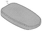
도 1은 본 발명의 실시 예에 따른 케이지모듈을 개략적으로 나타낸 사시도이다.
도 2 내지 도 4는 본 발명의 실시 예에 따른 케이지모듈에서 케이지의 예시적 형태를 개략적으로 나타낸 도면이다.
도 5와 도 6은 본 발명의 실시 예에 따른 케이지모듈의 케이지 중 일부 부분을 확대하여 개략적으로 나타낸 도면이다.
도 7는 본 발명의 실시 예에 따른 케이지장착기구세트의 벌룬모듈을 개략적으로 나타낸 사시도이다.
도 8 내지 도 10은 본 발명의 실시 예에 따른 케이지장착기구세트의 벌룬모듈에서 벌룬의 예시적 형태를 개략적으로 나타낸 도면이다.
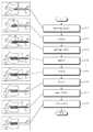
도 11은 본 발명의 실시 예에 따른 케이지모듈 장착방법을 개략적으로 나타낸 순서도이다.1 is a perspective view schematically showing a cage module according to an embodiment of the present invention.
2 to 4 are views schematically showing an exemplary form of a cage in the cage module according to an embodiment of the present invention.
5 and 6 are enlarged and schematic views of some parts of the cage of the cage module according to an embodiment of the present invention.
7 is a perspective view schematically showing a balloon module of a cage mounting mechanism set according to an embodiment of the present invention.
8 to 10 are views schematically showing exemplary shapes of balloons in the balloon module of the cage mounting mechanism set according to an embodiment of the present invention.
11 is a flowchart schematically illustrating a cage module mounting method according to an embodiment of the present invention.
이하에서는 본 발명에 대하여 보다 구체적으로 이해할 수 있도록 첨부된 도면을 참조한 바람직한 실시 예를 들어 설명하기로 한다.Hereinafter, a preferred embodiment will be described with reference to the accompanying drawings so that the present invention can be understood in more detail.
도 1은 본 발명의 실시 예에 따른 케이지모듈을 개략적으로 나타낸 사시도이고, 도 2 내지 도 4는 본 발명의 실시 예에 따른 케이지모듈에서 케이지의 예시적 형태를 개략적으로 나타낸 도면이고, 도 5와 도 6은 본 발명의 실시 예에 따른 케이지모듈의 케이지 중 일부 부분을 개략적으로 나타낸 도면이다.1 is a perspective view schematically showing a cage module according to an embodiment of the present invention, FIGS. 2 to 4 are views schematically showing an exemplary form of a cage in a cage module according to an embodiment of the present invention, and FIG. 6 is a view schematically showing a part of a cage of a cage module according to an embodiment of the present invention.
먼저, 도 1 내지 도 6을 참조하면, 본 발명의 실시 예에 따른 케이지모듈(100)은 케이지(120) 및 삽입관(110)을 포함하여 이루어진다.First, referring to FIGS. 1 to 6 , the
케이지(cage)(120)는 서로 이웃하는 척추골 사이의 간격인 추간 간격을 일정 수준 확보하기 위하여 서로 이웃하는 척추골 사이에 배치된다. 이러한 케이지(120)는 합금재질로 이루어진 것이 바람직하며, 소정의 온도 범위 내에서 외연이 확장된다. 케이지(120)의 외연이 확장됨에 따라 추간 간격이 확보된다.The cage (cage) 120 is disposed between the vertebrae adjacent to each other in order to secure a certain level of the intervertebral spacing, which is the distance between the vertebrae adjacent to each other. The
케이지(120)의 외연 확장이 이루어지는 온도 범위는 섭씨 36도 내지 37도 인 것이 바람직하다. 그리고 섭씨 36도 내지 37도의 온도 범위에서 케이지(120)의 외연 확장이 완료된 상태가 유지된다. 이러한 케이지(120)의 재질은 합금재질로서 니켈과 티타늄을 포함하는 니티놀(Nitinol) 과 같은 형상기억합금소재로 이루어진 것이 바람직하다.The temperature range at which the outer edge of the
케이지(120)는 와이어메쉬망 구조를 갖춘 것이 바람직하다. 케이지(120)의 외연 확장이 완료되는 섭씨 36도 내지 37도의 범위에서 케이지(120)의 외형적 형태는 와이어메쉬망으로 이루어진 주머니 또는 다공성블록체와 같은 형태를 갖는 것이 바람직하다.The
상온에서 케이지(120)는 접혀진 상태 또는 압축된 상태를 유지하고 있는 것이 바람직하다. 여기서 상온(room temperature)은 섭씨 20도 내지 25도 정도를 의미한다고 할 수 있다.At room temperature, the
도 1의 좌측에 도시된 바와 같이 접혀지거나 압축된 상태인 케이지(120)는 주변온도가 섭씨 36도 내지 37도 이거나 케이지(120) 자체의 온도가 섭씨 36도 내지 37도가 되면 도 1의 우측에 도시된 바와 같이 케이지(120)의 외연이 확장되어 추간 간격을 확보하고 유지할 수 있는 형태가 된다.As shown on the left side of FIG. 1, the
외연이 확장된 케이지(120)의 예시적인 몇몇 형태를 도 2 내지 도 4에 개략적으로 도시하였다.Some exemplary configurations of an expanded
도 2에 도시된 바와 같은 케이지(120)의 형태도 가능하며, ALIF(anterior lumbar interbody fusion) 전방 요추 융합시 선택하여 이용될 수도 있다. 도 3에 도시된 바와 같이 끝단 측이 둥근 유선형를 이루는 케이지(120)의 형태도 가능하며, 척추의 옆측에서 진입시키고자 할 때 선택하여 이용될 수도 있다. 도 4에 도시된 바와 같은 케이지(120)의 형태 또한 충분히 가능하며, 척추체 융합술 중 PLIF(posterior lumbar interbody fusion) 또는 TLIF(transforaminal lumbar interbody fusion)에 적용 가능한 형태이다.The form of the
이처럼 외연이 확장된 케이지(120)의 형태는 서로 이웃하는 척추골 사이에 배치시키기에 적절한 것으로 선택되어 척추골 사이에 장착될 수 있다.As such, the shape of the
케이지(120)는 도 5에서 참조되는 바와 같이 와이어로 형성된 메쉬망에서 뚫린 부분이 사각형의 형태를 갖춘 구조인 것도 바람직하며, 도 6에서 참조되는 바와 같이 와이어가 벌집 구조 즉, 육각형의 형태를 이루는 메쉬망 구조인 것 또한 바람직하다.The
이러한 와이어메쉬망이 한 장의 레이어(layer)로 이루어진 것도 바람직하며, 와이어메쉬망으로 이루어진 레이어가 다수개로서 겹층을 이루고 있는 것 또한 바람직하다.It is also preferable that such a wire mesh network is made of a single layer, and it is also preferable that a plurality of layers made of the wire mesh network are stacked.
삽입관(110)는 일측단이 케이지(120)에 결합되어 있으며, 일정한 길이의 파이프 형태를 갖추고 있다. 사용자가 삽입관(110)을 길이방향으로 밀거나 당김으로써 케이지(120)가 추간에서 배치되는 위치의 조절이 이루어질 수 있다.The
이러한 삽입관(110)는 파이프와 같은 형태로서, 케이지(120)의 내측공간과 연통될 수 있게 일측단이 케이지(120)와 결합된 것이 바람직하다.The
이와 같은 케이지모듈(100)을 이용하여 추간 간격을 일정수준 확보할 수 있다.A certain level of intervertebral spacing can be secured by using such a
다음으로 위와 같은 케이지모듈(100)을 포함하는 케이지장착기구세트에 대하여 설명을 이어가기로 한다.Next, the description of the cage mounting mechanism set including the
본 발명의 실시 예에 따른 케이지장착기구세트는 케이지모듈(100) 및 엔도스코피(300)를 포함하여 이루어지며, 바람직하게는 벌룬모듈(200)을 더 포함하여 이루어질 수 있다.The cage mounting mechanism set according to an embodiment of the present invention is made to include the
케이지모듈(100)은 앞서 설명한 바와 대동소이하며, 앞서 설명한 것으로 대신하기로 한다.The
엔도스코피(300)는 적어도 일부분이 파이프와 같은 형태를 갖추고 있으며, 케이지모듈(100)의 적어도 일부분이 엔도스코피(300)에 삽입된다. 그리고 엔도스코피(300)에 삽입된 케이지모듈(100)의 적어도 일부분이 서로 이웃하는 척추골 사이로 배치되는 이동을 가이드한다.At least a portion of the
이러한 엔도스코피(300)의 내측 홀의 직경은 케이지모듈(100)의 삽입관(110)의 외경보다 큰 것이 바람직하다. 아울러 케이지모듈(100)의 케이지(120)가 압축된 상태 또는 접혀진 상태일 때 폭 또는 너비가 엔도스코피(300)의 내측 홀의 직경보다 작은 것이 바람직하다.It is preferable that the diameter of the inner hole of the
벌룬모듈(200)은 케이지모듈(100)의 삽입관(110)을 통해 주입될 수 있다. 그리고 삽입관(110)을 통해 주입되는 벌룬모듈(200)의 적어도 일부분이 케이지(120) 내측공간으로 배치된다.The
도 7은 본 발명의 실시 예에 따른 케이지장착기구세트의 벌룬모듈을 개략적으로 나타낸 도면이다.7 is a view schematically showing a balloon module of a cage mounting mechanism set according to an embodiment of the present invention.
도 7에서 참조되는 바와 같이 벌룬모듈(200)은 벌룬(220) 및 유체주입관(210)를 포함하여 이루어진다.As shown in FIG. 7 , the
벌룬(220)은 케이지모듈(100)의 케이지(120) 내측 공간에서 팽창하여 케이지(120)의 외연 확장을 지원한다. 앞서 언급한 바와 같이 케이지(120)는 섭씨 36도 내지 37도에서 외연이 확장된다.The
이 때 케이지(120)의 외연이 확장되는 것을 돕기 위하여 케이지(120)의 내측공간에서 벌룬(220)이 팽창함으로써 케이지(120)가 확장된 형태를 좀 더 빨리 갖출 수 있도록 밀어주게 된다.At this time, in order to help the outer edge of the
즉, 도 7의 좌측에 도시된 바와 같이 축소된 형태를 갖추고 있는 벌룬(220)이 도 7의 우측에 도시된 바와 같이 팽창된 형태를 갖추게 된다. 이와 같이 벌룬(220)이 팽창된 형태를 갖추면서 케이지(120)의 외연이 확장되도록 밀어주게 된다는 것이다.That is, the
따라서 케이지(120)의 외연이 확장된 형태를 갖추는데 소요되는 시간을 단축시켜 줄 수 있다.Therefore, it is possible to shorten the time required for the outer periphery of the
아울러, 벌룬(220)의 팽창된 형태가 케이지(120)의 외연이 확장된 형태와 동일하거나 유사한 것이 바람직하다.In addition, it is preferable that the expanded shape of the
도 8 내지 도 10은 본 발명의 실시 예에 따른 케이지모듈구의 벌룬모듈에서 벌룬의 예시적 형태를 개략적으로 나타낸 도면이다.8 to 10 are views schematically showing exemplary shapes of balloons in the balloon module of the cage module unit according to an embodiment of the present invention.
예를 들어, 케이지(120)의 외연이 확장된 형태가 도 2에 도시된 바와 같은 형태인 경우 벌룬(220)의 팽창된 형태 또한 도 8에서 참조되는 바와 같이 유사한 형태를 갖춘 것이 바람직하다.For example, when the form in which the outer edge of the
케이지(120)의 외연이 확장된 형태가 도 3에 도시된 바와 같은 형태인 경우 벌룬(220)의 팽창된 형태 또한 도 9에서 참조되는 바와 같이 유사한 형태를 갖춘 것이 바람직하다.When the form in which the outer periphery of the
케이지(120)의 외연이 확장된 형태가 도 4에 도시된 바와 같은 형태인 경우 벌룬(220)의 팽창된 형태 또한 도 10에서 참조되는 바와 같은 유사한 형태를 갖춘 것이 바람직하다.When the expanded shape of the
유체주입관(210)은 도 7에서 참조되는 바와 같이 일측단이 벌룬(220)과 결합되며, 벌룬(220)이 팽창되도록 외부로부터 주입되는 공기와 같은 유체를 벌룬(220)의 내측으로 이동시켜준다.As shown in FIG. 7 , one end of the
파이프 형태를 갖춘 유체주입관(210)의 일측단이 벌룬(220)과 결합되어 유체주입관(210)와 벌룬(220)은 연통된다. 그리고 유체주입관(210)의 타측단으로부터 주입된 유체는 유체주입관(210)을 따라 일측단으로 이동된 후 벌룬(220)의 내측공간으로 주입된다.One end of the
유체주입관(210)을 통해 벌룬(220)의 내측공간으로 유체가 주입됨으로써 앞서 언급한 바와 같이 벌룬(220)은 팽창하게 되며, 케이지모듈(100)의 케이지(120)의 외연이 확장되도록 지원하게 된다.As the fluid is injected into the inner space of the
그리고, 벌룬(220) 내부에 채워져 있던 유체가 유체주입관(210)을 통해 외부로 배출되면 팽창되어 있던 벌룬(220)은 다시 축소된 형태로 복귀하게 된다.And, when the fluid filled in the
이러한 유체주입관(210)은 외경이 케이지모듈(100)의 삽입관(110)의 내경보다 작은 것이 바람직하다. 또한, 도 7의 좌측에 도시된 바와 같이 벌룬(220)이 축소된 형태일 때의 너비 또는 폭 또한 케이지모듈(100)의 삽입관(110)의 내경보다 작은 것이 바람직하다.It is preferable that the outer diameter of the
이상에서 설명한 바와 같은 본 발명의 실시 예에 따른 케이지모듈 장착방법에 대하여 설명을 이어가기로 한다.The description of the cage module mounting method according to the embodiment of the present invention as described above will be continued.
도 11은 본 발명의 실시 예에 따른 케이지모듈 장착방법을 개략적으로 나타낸 순서도이다.11 is a flowchart schematically illustrating a cage module mounting method according to an embodiment of the present invention.
도 11을 더 참조하면, 본 발명의 실시 예에 따른 케이지모듈 장착방법은 기본적으로 케이지모듈삽입단계(S110) 및 확장단계(S120)를 포함하며, 좀 더 바람직하게는 벌룬삽입단계(S130), 팽창단계(S140), 수축단계(S150), 제거단계(S160), 인공뼈주입단계(S170) 및 삽입관제거단계(S180)를 더 포함하여 이루어질 수 있다.11, the cage module mounting method according to an embodiment of the present invention basically includes a cage module insertion step (S110) and an expansion step (S120), and more preferably a balloon insertion step (S130), The expansion step (S140), the contraction step (S150), the removal step (S160), the artificial bone injection step (S170) and the cannulation removal step (S180) may be further included.
<< S110 >><< S110 >>
케이지모듈삽입단계(S110)는 서로 이웃하는 척추골(1, 2) 사이(10)로 배치이동을 가이드하는 엔도스코피(300)에 케이지모듈(100)가 삽입되는 단계이다.The cage module insertion step (S110) is a step in which the
도 11에서 참조되는 바와 같이, 서로 이웃하는 척추골(1, 2) 사이(10)를 엔도스코피(300)가 지향하면서 근접 배치되어 있다.As shown in FIG. 11 , the
그리고, 케이지모듈(100)의 케이지(120)를 배치시킬 추간(1, 2) 사이(10)의 부분을 엔도스코피(300)의 일측단이 지향하는 상태에서 케이지모듈(100)을 엔도스코피(300)의 타측단에 삽입한다. 케이지모듈(100)의 케이지(120)가 추간(1, 2) 사이(10)의 부분에 위치될 때까지 엔도스코피(300)의 내측을 통해 추간(1, 2) 사이(10)로 케이지(120)를 이동시킨다. And, in a state where one end of the
따라서, 엔도스코피(300)의 가이드에 따라 케이지(120)가 추간(1, 2) 사이(10)의 부분에 배치된다.Accordingly, the
<< S120 >><< S120 >>
확장단계(S120)는 상기 케이지모듈삽입단계(S110)에서 엔도스코피(300)에 삽입된 케이지모듈(100)의 케이지(120)가 서로 이웃하는 척추골(1, 2) 사이(10)에서 외연 확장이 이루어지는 단계이다.In the expansion step (S120), the
케이지모듈삽입단계(S110)에서 추간(1, 2) 사이(10)의 부분에 배치된 케이지(120)는 주변의 온도가 섭씨 36도 내지 37도 이다. 주변으로부터 열이 케이지(120)로 전달되므로 케이지(120)의 온도는 상승된다.In the cage module insertion step (S110), the
케이지(120)의 온도가 상승됨에 따라 형상기억합금 소재로 이루어진 케이지(120)는 접혀진 상태 또는 축소된 상태에서 점차 외연이 확장된다.As the temperature of the
<< S130 >><< S130 >>
벌룬삽입단계(S130)는 확장단계(S120)에서 외연이 확장되는 케이지모듈(100)의 케이지(120) 내측 공간으로 벌룬모듈(200)의 벌룬(220)이 삽입되어 배치되는 단계이다.The balloon insertion step (S130) is a step in which the
확장단계(S120)에 놓인 케이지모듈(100)의 케이지(120)는 외연이 확장되면서 내부에 공간이 증대된다. 이 때 벌룬모듈(200)을 케이지모듈(100)의 삽입관(110) 타측단에 삽입시킨다. 다시 말해서, 벌룬모듈(200)의 벌룬(220)이 케이지모듈(100)의 삽입관(110) 타측단을 통해 삽입되어 삽입관(110)의 일측단까지 위치 이동을 시킨다.As the outer edge of the
그리고 벌룬(220)이 삽입관(110)의 일측단을 지나면서 삽입관(110)을 통과하게 되며, 도 11에서 참조되는 바와 같이 벌룬(220)은 케이지(120)의 내측 공간에 위치된다. 그리고 벌룬(220)과 결합되어 있는 유체주입관(210)는 삽입관(110) 내측에 위치된다.And the
<< S140 >><< S140 >>
팽창단계(S140)는 케이지(120) 내측 공간에 배치된 벌룬(220)이 팽창하는 단계이다. 케이지(120) 내측 공간에 배치된 벌룬(220)을 팽창시키기 위하여 유체주입관(210)를 통해 벌룬(220)의 내측공간 으로 공기 또는 질소가스와 같은 유체를 주입시킨다.The expansion step (S140) is a step in which the
벌룬(220)의 내측공간으로 주입되는 유체에 의해 벌룬(220)은 팽창된다.The
벌룬(220)이 팽창됨에 따라 벌룬(220)의 외면이 케이지(120)의 내측에 접하게 되고, 케이지(120)의 외연이 확장되도록 케이지(120)의 내측에서 외측방향으로 케이지(120)를 밀어준다. 따라서, 외연이 확장되는 케이지(120)가 좀 더 원활하게 외연이 확장되도록 벌룬(220)이 팽창된다.As the
<< S150 >><< S150 >>
수축단계(S150)는 팽창단계(S140)에서 팽창된 벌룬(220)이 수축되는 단계이다.The contraction step (S150) is a step in which the
팽창단계(S140)를 통해 케이지(120)의 외연이 충분히 확장되어 추간(1, 2) 간격을 일정 수준 이상 확보되면 벌룬(220) 내부에 채워진 유체를 유체주입관(210)를 통해 외부로 배출시킨다. 벌룬(220) 내부에 있던 유체가 배출되면서 벌룬(220)은 수축된다.When the outer periphery of the
<< S160 >><< S160 >>
제거단계(S160)는 수축단계(S150)에서 수축된 벌룬모듈(200)을 인출하여 제거하는 단계이다.The removing step (S160) is a step of withdrawing and removing the
수축단계(S150)에서 풍선체 내부에 있던 유체가 배출됨에 따라 벌룬(220)은 수축된다. 벌룬(220)이 수축된 후 유체주입관(210)를 당겨주면 벌룬(220)은 케이지(120)의 내측에서 삽입관(110)의 내측으로 이동된다.In the contraction step (S150), as the fluid inside the balloon body is discharged, the
계속하여 유체주입관(210)를 당겨주면 삽입관(110)의 타측단을 통해 벌룬(220)이 인출된다. 벌룬(220)이 삽입관(110)의 타측단을 통해 인출됨으로써 벌룬모듈(200)의 인출이 완료되며, 도 11에서 참조되는 바와 같이 추간(1, 2) 사이(10)에 케이지(120)가 남겨지게 된다.If the
<< S170 >><< S170 >>
제거단계(S160) 이후 필요에 따라서는 인공뼈주입단계(S170)를 추가적으로 실시하는 것 또한 바람직하다.It is also preferable to additionally perform the artificial bone injection step (S170) if necessary after the removal step (S160).
인공뼈주입단계(S170)는 제거단계(S160)에서 벌룬모듈(200)가 제거된 케이지모듈(100)의 케이지(120)의 내측으로 인공뼈를 주입시키는 단계이다.The artificial bone injection step (S170) is a step of injecting artificial bone into the inside of the
도 11에서 참조되는 바와 같이, 인공뼈를 주입시키기 위하여 인공뼈주입관(400)이 엔도스코프(300)을 통해 케이지(120) 측으로 삽입된다. 그리고 인공뼈주입관(400)을 통해 인공뼈가 주입된다.11 , the artificial
여기서 인공뼈는 케이지(120)와 함께 추간 사이의 간격을 안정적으로 확보할 수 있도록 케이지(120) 내에 채워지는 성형재료인 것이 바람직하다. 주입된 인공뼈는 케이지(120) 내부 공간을 채워줄 수 있으며, 케이지(120)의 표면에도 분포될 수 있다.Here, it is preferable that the artificial bone is a molding material filled in the
<< S180 >><< S180 >>
삽입관제거단계(S180)는 인공뼈주입단계(S170)에서 인공뼈가 주입된 케이지모듈(100)의 케이지(120)에 결합된 삽입관(110)을 케이지(120)로부터 분리 제거시키는 단계이다.The insertion tube removal step (S180) is a step of separating and removing the
케이지(120)와 결합된 삽입관(110)의 일측 부분을 절단시킴으로써 삽입관(110)을 케이지(120)로부터 분리 및 제거시키게 된다.The
인공뼈주입단계(S170)가 생략되는 경우 삽입관제거단계(S180)는 앞서 설명한 제거단계(S160) 다음에 이루어질 수도 있으며 이 또한 바람직하다.When the artificial bone injection step (S170) is omitted, the cannula removal step (S180) may be performed after the removal step (S160) described above, and this is also preferable.
이상에서 설명한 바와 같이 본 발명에 따른 확장형 케이지모듈, 케이지장착기구세트 및 이의 장착방법은 안정적으로 서로 이웃하는 척추골 사이의 간격을 확보할 수 있으면서 동시에 절개 부위를 대폭 축소시킬 수 있다는 장점이 있다. 또한 장착과정이 용이하므로 작업의 능률과 편의가 증진되는 장점도 있다.As described above, the expandable cage module, the cage mounting mechanism set, and the mounting method thereof according to the present invention have the advantage that it is possible to stably secure a gap between the adjacent vertebrae and at the same time greatly reduce the incision site. In addition, since the installation process is easy, there is an advantage that work efficiency and convenience are improved.
이상에서 설명된 바와 같이, 본 발명에 대한 구체적인 설명은 첨부된 도면을 참조한 실시 예들에 의해서 이루어졌지만, 상술한 실시 예들은 본 발명의 바람직한 실시 예를 들어 설명하였을 뿐이기 때문에, 본 발명이 상기의 실시 예에만 국한되는 것으로 이해되어져서는 아니되며, 본 발명의 권리범위는 후술하는 청구범위 및 그 등가개념으로 이해되어져야 할 것이다.As described above, the detailed description of the present invention has been made by the embodiments with reference to the accompanying drawings, but since the above-described embodiments have only been described with reference to the preferred embodiments of the present invention, the present invention It should not be construed as being limited only to the embodiments, and the scope of the present invention should be understood as the following claims and their equivalents.
100 : 케이지모듈
110 : 삽입관 120 : 케이지
200 : 벌룬모듈
210 : 유체주입관 220 : 벌룬
300 : 엔도스코피(endoscopy)100: cage module
110: insertion tube 120: cage
200: balloon module
210: fluid injection pipe 220: balloon
300: endoscopy (endoscopy)
Claims (12)
Translated fromKorean적어도 일부분이 파이프 형태를 갖추고 있으며, 상기 케이지모듈의 적어도 일부분이 삽입되어 서로 이웃하는 척추골 사이로 배치되는 이동을 가이드하는 엔도스코피;를 포함하되,
상기 케이지모듈은,
합금재질로 이루어지고 소정의 온도 범위 내에서 외연이 확장되어 추간 간격을 확보하는 케이지; 및
일측단이 상기 케이지에 결합되며, 파이프 형태를 갖춘 삽입관;을 포함하고,
상기 케이지모듈의 상기 삽입관을 통해 주입되며, 적어도 일부분이 상기 케이지내측 공간에 배치되는 벌룬모듈; 을 더 포함하되,
상기 벌룬모듈은,
상기 케이지모듈의 상기 케이지 내측 공간에서 팽창하여 상기 케이지의 외연 확장을 지원하는 벌룬; 및
일측단이 상기 벌룬과 결합되며, 상기 벌룬이 팽창되도록 외부로부터 주입되는 유체를 상기 벌룬의 내측으로 이동시켜주는 유체주입관;을 포함하고,
상기 유체주입관은 상기 삽입관 내측에 위치하되,
상기 유체주입관을 당기면 상기 삽입관의 일측단을 통해 상기 벌룬이 인출되는 것을 특징으로 하는 케이지장착기구세트.a cage module, a portion of which is disposed between adjacent vertebrae to secure an intervertebral space; and
At least a portion has a pipe shape, and at least a portion of the cage module is inserted into an endoscopic guide to guide movement disposed between adjacent vertebrae; including,
The cage module,
a cage made of an alloy material and having an outer edge extended within a predetermined temperature range to secure an intervertebral space; and
One end is coupled to the cage, the insertion tube having a pipe shape; including,
a balloon module injected through the insertion tube of the cage module, at least a portion of which is disposed in the space inside the cage; further comprising,
The balloon module,
a balloon that expands in the cage inner space of the cage module to support an outer edge expansion of the cage; and
a fluid injection tube having one end coupled to the balloon and moving the fluid injected from the outside to the inside of the balloon to inflate the balloon;
The fluid injection tube is located inside the insertion tube,
When the fluid injection tube is pulled, the cage mounting mechanism set, characterized in that the balloon is drawn out through one end of the insertion tube.
Priority Applications (1)
| Application Number | Priority Date | Filing Date | Title |
|---|---|---|---|
| KR1020190066579AKR102297977B1 (en) | 2019-06-05 | 2019-06-05 | Expandable Cage Module, Balloon Module and Cage Installation Device Set Including thereof and installing Method thereof |
Applications Claiming Priority (1)
| Application Number | Priority Date | Filing Date | Title |
|---|---|---|---|
| KR1020190066579AKR102297977B1 (en) | 2019-06-05 | 2019-06-05 | Expandable Cage Module, Balloon Module and Cage Installation Device Set Including thereof and installing Method thereof |
Publications (2)
| Publication Number | Publication Date |
|---|---|
| KR20200140950A KR20200140950A (en) | 2020-12-17 |
| KR102297977B1true KR102297977B1 (en) | 2021-09-08 |
Family
ID=74089927
Family Applications (1)
| Application Number | Title | Priority Date | Filing Date |
|---|---|---|---|
| KR1020190066579AActiveKR102297977B1 (en) | 2019-06-05 | 2019-06-05 | Expandable Cage Module, Balloon Module and Cage Installation Device Set Including thereof and installing Method thereof |
Country Status (1)
| Country | Link |
|---|---|
| KR (1) | KR102297977B1 (en) |
Families Citing this family (1)
| Publication number | Priority date | Publication date | Assignee | Title |
|---|---|---|---|---|
| CN114392017A (en)* | 2022-01-28 | 2022-04-26 | 山东第一医科大学附属省立医院(山东省立医院) | Inflatable and expandable fixable intervertebral fusion device and treatment system using same |
Citations (3)
| Publication number | Priority date | Publication date | Assignee | Title |
|---|---|---|---|---|
| US20010032020A1 (en)* | 1999-07-02 | 2001-10-18 | Petrus Besselink | Reinforced expandable cage |
| US20040133280A1 (en)* | 2002-11-21 | 2004-07-08 | Trieu Hai H. | Systems and techniques for interbody spinal stabilization with expandable devices |
| US20080114454A1 (en)* | 2006-11-10 | 2008-05-15 | Warsaw Orthopedic, Inc. | Expandable Vertebral Body Implants Including Shape-Memory Materials and Methods of Use |
Family Cites Families (2)
| Publication number | Priority date | Publication date | Assignee | Title |
|---|---|---|---|---|
| KR100905962B1 (en) | 2008-03-17 | 2009-07-06 | 조철민 | Intervertebral expansion cage device and mounting method |
| KR101159040B1 (en)* | 2009-10-08 | 2012-06-21 | 최길운 | Instrument maintaining a space of the vertebra and vertebra fixation system of using same |
- 2019
- 2019-06-05KRKR1020190066579Apatent/KR102297977B1/enactiveActive
Patent Citations (3)
| Publication number | Priority date | Publication date | Assignee | Title |
|---|---|---|---|---|
| US20010032020A1 (en)* | 1999-07-02 | 2001-10-18 | Petrus Besselink | Reinforced expandable cage |
| US20040133280A1 (en)* | 2002-11-21 | 2004-07-08 | Trieu Hai H. | Systems and techniques for interbody spinal stabilization with expandable devices |
| US20080114454A1 (en)* | 2006-11-10 | 2008-05-15 | Warsaw Orthopedic, Inc. | Expandable Vertebral Body Implants Including Shape-Memory Materials and Methods of Use |
Also Published As
| Publication number | Publication date |
|---|---|
| KR20200140950A (en) | 2020-12-17 |
Similar Documents
| Publication | Publication Date | Title |
|---|---|---|
| US8118844B2 (en) | Expandable device for insertion between anatomical structures and a procedure utilizing same | |
| US11051950B2 (en) | Expansible intersomatic cage | |
| JP5539954B2 (en) | Vertebral height recovery vertebral device | |
| EP2046217B1 (en) | Apparatus for insertion between anatomical structures | |
| US5549635A (en) | Non-deformable self-expanding parallel flow endovascular stent and deployment apparatus therefore | |
| ES2336592T3 (en) | EMBOLIC PROTECTION DEVICE. | |
| US9901464B2 (en) | Methods and apparatus for an insertion guide device | |
| US8062337B2 (en) | Expandable device for insertion between anatomical structures and a procedure utilizing same | |
| US20060264945A1 (en) | Selectively-expandable bone scaffold | |
| US20070162136A1 (en) | Nucleus pulposus trial device and technique | |
| JP2006507090A (en) | System for intravertebral reduction | |
| KR20120047231A (en) | Expanding intervertebral device and methods of use | |
| HUP0302570A2 (en) | Tool to direct bond replacement material | |
| JP2001276099A (en) | Method for fixing adjacent vertebrae of spine and orthopedic implant for transplantation between adjacent vertebrae of spine | |
| JP2020049216A (en) | Intrasaccular device positioning and deployment system | |
| KR20180072675A (en) | Expanded intervertebral cage device with living hinge, system and method of manufacturing the same | |
| KR102297977B1 (en) | Expandable Cage Module, Balloon Module and Cage Installation Device Set Including thereof and installing Method thereof | |
| JP2008504872A (en) | C-shaped intervertebral disc prosthesis | |
| KR20200025127A (en) | Stent-type catheter to be used like balloon catheter | |
| JP2005137418A (en) | Expandable osteosynthesis cage | |
| CN113813088B (en) | Annular interbody fusion system under full endoscope of backbone | |
| EP3367976B1 (en) | An expandable cage | |
| KR102262993B1 (en) | Expandable fusion device and intervertebral fusion system | |
| US20210251775A1 (en) | Deployable Ramped Nose for Implantable Medical Devices | |
| TW202521076A (en) | Flexible interbody cage |
Legal Events
| Date | Code | Title | Description |
|---|---|---|---|
| PA0109 | Patent application | Patent event code:PA01091R01D Comment text:Patent Application Patent event date:20190605 | |
| PA0201 | Request for examination | ||
| PG1501 | Laying open of application | ||
| E902 | Notification of reason for refusal | ||
| PE0902 | Notice of grounds for rejection | Comment text:Notification of reason for refusal Patent event date:20210224 Patent event code:PE09021S01D | |
| E701 | Decision to grant or registration of patent right | ||
| PE0701 | Decision of registration | Patent event code:PE07011S01D Comment text:Decision to Grant Registration Patent event date:20210825 | |
| GRNT | Written decision to grant | ||
| PR0701 | Registration of establishment | Comment text:Registration of Establishment Patent event date:20210830 Patent event code:PR07011E01D | |
| PR1002 | Payment of registration fee | Payment date:20210831 End annual number:3 Start annual number:1 | |
| PG1601 | Publication of registration | ||
| PR1001 | Payment of annual fee | Payment date:20240829 Start annual number:4 End annual number:4 | |
| PR1001 | Payment of annual fee | Payment date:20250512 Start annual number:5 End annual number:5 |