KR102297101B1 - Method and apparatus for performing wireless communication in unlicensed band - Google Patents
Method and apparatus for performing wireless communication in unlicensed bandDownload PDFInfo
- Publication number
- KR102297101B1 KR102297101B1KR1020190083074AKR20190083074AKR102297101B1KR 102297101 B1KR102297101 B1KR 102297101B1KR 1020190083074 AKR1020190083074 AKR 1020190083074AKR 20190083074 AKR20190083074 AKR 20190083074AKR 102297101 B1KR102297101 B1KR 102297101B1
- Authority
- KR
- South Korea
- Prior art keywords
- ssb
- transmitted
- information
- index
- lbt
- Prior art date
- Legal status (The legal status is an assumption and is not a legal conclusion. Google has not performed a legal analysis and makes no representation as to the accuracy of the status listed.)
- Active
Links
Images


Classifications
- H—ELECTRICITY
- H04—ELECTRIC COMMUNICATION TECHNIQUE
- H04W—WIRELESS COMMUNICATION NETWORKS
- H04W56/00—Synchronisation arrangements
- H04W56/001—Synchronization between nodes
- H—ELECTRICITY
- H04—ELECTRIC COMMUNICATION TECHNIQUE
- H04W—WIRELESS COMMUNICATION NETWORKS
- H04W74/00—Wireless channel access
- H04W74/08—Non-scheduled access, e.g. ALOHA
- H04W74/0866—Non-scheduled access, e.g. ALOHA using a dedicated channel for access
- H04W74/0891—Non-scheduled access, e.g. ALOHA using a dedicated channel for access for synchronized access
- H—ELECTRICITY
- H04—ELECTRIC COMMUNICATION TECHNIQUE
- H04W—WIRELESS COMMUNICATION NETWORKS
- H04W16/00—Network planning, e.g. coverage or traffic planning tools; Network deployment, e.g. resource partitioning or cells structures
- H04W16/24—Cell structures
- H04W16/28—Cell structures using beam steering
- H—ELECTRICITY
- H04—ELECTRIC COMMUNICATION TECHNIQUE
- H04W—WIRELESS COMMUNICATION NETWORKS
- H04W24/00—Supervisory, monitoring or testing arrangements
- H04W24/08—Testing, supervising or monitoring using real traffic
- H—ELECTRICITY
- H04—ELECTRIC COMMUNICATION TECHNIQUE
- H04W—WIRELESS COMMUNICATION NETWORKS
- H04W24/00—Supervisory, monitoring or testing arrangements
- H04W24/10—Scheduling measurement reports ; Arrangements for measurement reports
- H—ELECTRICITY
- H04—ELECTRIC COMMUNICATION TECHNIQUE
- H04W—WIRELESS COMMUNICATION NETWORKS
- H04W56/00—Synchronisation arrangements
- H04W72/042—
- H—ELECTRICITY
- H04—ELECTRIC COMMUNICATION TECHNIQUE
- H04W—WIRELESS COMMUNICATION NETWORKS
- H04W74/00—Wireless channel access
- H04W74/08—Non-scheduled access, e.g. ALOHA
- H04W74/0808—Non-scheduled access, e.g. ALOHA using carrier sensing, e.g. carrier sense multiple access [CSMA]
- H04W74/0816—Non-scheduled access, e.g. ALOHA using carrier sensing, e.g. carrier sense multiple access [CSMA] with collision avoidance
- H—ELECTRICITY
- H04—ELECTRIC COMMUNICATION TECHNIQUE
- H04W—WIRELESS COMMUNICATION NETWORKS
- H04W16/00—Network planning, e.g. coverage or traffic planning tools; Network deployment, e.g. resource partitioning or cells structures
- H04W16/14—Spectrum sharing arrangements between different networks
- H—ELECTRICITY
- H04—ELECTRIC COMMUNICATION TECHNIQUE
- H04W—WIRELESS COMMUNICATION NETWORKS
- H04W74/00—Wireless channel access
- H04W74/08—Non-scheduled access, e.g. ALOHA
- H04W74/0808—Non-scheduled access, e.g. ALOHA using carrier sensing, e.g. carrier sense multiple access [CSMA]
Landscapes
- Engineering & Computer Science (AREA)
- Computer Networks & Wireless Communication (AREA)
- Signal Processing (AREA)
- Mobile Radio Communication Systems (AREA)
Abstract
Translated fromKoreanDescription
Translated fromKorean본 실시예들은 차세대 무선 액세스 망(이하, "NR[New Radio]"라 함)에서 비면허 대역에 대한 LBT(Listen Before Talk) 결과를 고려하여 무선 통신을 수행하는 방법 및 장치에 대해서 제안한다.The present embodiments propose a method and apparatus for performing wireless communication in consideration of a Listen Before Talk (LBT) result for an unlicensed band in a next-generation radio access network (hereinafter referred to as "New Radio [NR]").
3GPP는 최근 차세대 무선 액세스 기술(다시 말하면, 5G 무선 액세스 기술)에 대한 연구를 위한 스터디 아이템인 "Study on New Radio Access Technology"를 승인하고, 이를 기반으로 RAN WG1에서는 각각 NR(New Radio)을 위한 프레임 구조(frame structure), 채널 코딩 및 변조(channel coding & modulation), 파형 및 다중 접속 방식(waveform & multiple access scheme) 등에 대한 설계가 진행 중이다. NR은 LTE에 대비하여 향상된 데이터 전송률뿐만 아니라 세분화되고 구체화된 사용 시나리오(usage scenario) 별로 요구되는 다양한 QoS 요구(QoS requirements)를 만족시킬 수 있는 설계가 이루어지도록 요구되고 있다.3GPP recently approved "Study on New Radio Access Technology", a study item for research on next-generation radio access technology (that is, 5G radio access technology), and based on this, RAN WG1 for NR (New Radio) Design of a frame structure, channel coding & modulation, waveform & multiple access scheme, and the like is in progress. NR is required to be designed to satisfy various QoS requirements required for each segmented and detailed usage scenario as well as an improved data rate compared to LTE.
NR의 대표적 사용 시나리오로서 eMBB(enhancement Mobile BroadBand), mMTC(massive Machine Type Communication) 및 URLLC(Ultra Reliable and Low Latency Communications)가 정의되었으며, 각각의 사용 시나리오 별 요구를 만족시키기 위하여 LTE 대비 플렉서블한 프레임 구조 설계가 요구되고 있다.As representative usage scenarios of NR, eMBB (enhancement Mobile BroadBand), mMTC (massive machine type communication), and URLLC (Ultra Reliable and Low Latency Communications) have been defined. design is required.
각각의 서비스 요건(usage scenario)은 데이터 속도(data rates), 지연속도(latency), 신뢰도(reliability), 커버리지(coverage) 등에 대한 요구가 서로 상이하기 때문에 임의의 NR 시스템을 구성하는 주파수 대역을 통해 각각의 사용 시나리오별 요구를 효율적으로 만족시키기 위한 방법으로서 서로 다른 뉴머롤로지(numerology)(예를 들어, 서브캐리어 스페이싱(subcarrier spacing), 서브프레임(subframe), TTI(Transmission Time Interval) 등) 기반의 무선 자원 유닛(unit)을 효율적으로 멀티플렉싱(multiplexing)하는 방안에 대한 필요성이 제기되고 있다.Since each service requirement (usage scenario) has different requirements for data rates, latency, reliability, coverage, etc., through the frequency band constituting an arbitrary NR system As a method to efficiently satisfy the needs of each usage scenario, different numerology (eg, subcarrier spacing, subframe, Transmission Time Interval (TTI), etc.) based There is a need for a method for efficiently multiplexing a radio resource unit of
이러한 측면의 일환으로, NR에서 비면허 대역(unlicensed band)을 이용하여 무선 통신을 수행하기 위하여, 동기 신호 블록(Synchronization Signal Block; SSB)을 송수신하기 위한 설계가 필요하게 된다.As part of this aspect, in order to perform wireless communication using an unlicensed band in NR, a design for transmitting and receiving a synchronization signal block (SSB) is required.
본 실시예들은, 비면허 대역에의 접속을 위한 동기 신호 블록의 전송 시, LBT 결과를 고려하여 동기 신호 블록의 송수신 복잡도를 최소화할 수 있는 비면허 대역에서 무선 통신을 수행하는 방법 및 장치를 제공할 수 있다.The present embodiments provide a method and apparatus for performing wireless communication in an unlicensed band that can minimize the transmission/reception complexity of the synchronization signal block in consideration of the LBT result when transmitting the synchronization signal block for access to the unlicensed band. have.
또한, 본 실시예들은, 비면허 대역에서 LBT 기반 빔포밍 패턴의 적용 및 빔 추정을 수행할 수 있는 구체적인 방법 및 장치를 제공할 수 있다.In addition, the present embodiments may provide a specific method and apparatus capable of performing beam estimation and application of an LBT-based beamforming pattern in an unlicensed band.
일 측면에서, 본 실시예들은 단말이 비면허 대역에서 무선 통신을 수행하는 방법에 있어서, 비면허 대역에서의 동기 신호 블록(Synchronization Signal Block; SSB) 버스트 셋(burst set)에 대한 설정 정보를 수신하는 단계, 비면허 대역에 대한 LBT(Listen Before Talk) 결과에 기초한 SSB 버스트 셋에서 SSB가 전송되는 전송 구간 정보를 수신하는 단계 및 전송 구간 정보에 기초하여 SSB 버스트 셋에서 SSB를 검출하는 단계를 포함하는 방법을 제공할 수 있다.In one aspect, the present embodiments in a method for a terminal to perform wireless communication in an unlicensed band, the step of receiving configuration information for a synchronization signal block (Synchronization Signal Block; SSB) burst set in the unlicensed band , a method comprising the steps of receiving the transmission interval information in which the SSB is transmitted in the SSB burst set based on the LBT (Listen Before Talk) result for the unlicensed band and detecting the SSB in the SSB burst set based on the transmission interval information. can provide
다른 측면에서, 본 실시예들은 기지국이 비면허 대역에서 무선 통신을 수행하는 방법에 있어서, 비면허 대역에서의 동기 신호 블록(Synchronization Signal Block; SSB) 버스트 셋(burst set)에 대한 설정 정보를 전송하는 단계, 비면허 대역에서의 SSB 버스트 셋에 대한 LBT(Listen Before Talk)를 수행하는 단계 및 LBT 결과에 기초한 SSB 버스트 셋에서 SSB가 전송되는 전송 구간 정보를 전송하는 단계를 포함하는 방법을 제공할 수 있다.In another aspect, the present embodiments provide a method for a base station to perform wireless communication in an unlicensed band, the step of transmitting configuration information for a synchronization signal block (SSB) burst set in the unlicensed band , performing a Listen Before Talk (LBT) for the SSB burst set in the unlicensed band, and transmitting information on the transmission period in which the SSB is transmitted in the SSB burst set based on the LBT result.
또 다른 측면에서, 본 실시예들은 비면허 대역에서 무선 통신을 수행하는 단말에 있어서, 비면허 대역에서의 동기 신호 블록(Synchronization Signal Block; SSB) 버스트 셋(burst set)에 대한 설정 정보를 수신하고, 비면허 대역에 대한 LBT(Listen Before Talk) 결과에 기초한 SSB 버스트 셋에서 SSB가 전송되는 전송 구간 정보를 수신하는 수신부 및 전송 구간 정보에 기초하여 SSB 버스트 셋에서 SSB를 검출하는 제어부를 포함하는 단말을 제공할 수 있다.In another aspect, the present embodiments, in a terminal performing wireless communication in an unlicensed band, receive configuration information for a synchronization signal block (SSB) burst set in the unlicensed band, and A terminal comprising a receiver for receiving transmission section information in which the SSB is transmitted in the SSB burst set based on the LBT (Listen Before Talk) result for the band, and a controller for detecting the SSB in the SSB burst set based on the transmission section information. can
또 다른 측면에서, 본 실시예들은 비면허 대역에서 무선 통신을 수행하는 기지국에 있어서, 비면허 대역에서의 동기 신호 블록(Synchronization Signal Block; SSB) 버스트 셋(burst set)에 대한 LBT(Listen Before Talk)를 수행하는 제어부 및 비면허 대역에서의 SSB 버스트 셋에 대한 설정 정보를 전송하고, LBT 결과에 기초한 SSB 버스트 셋에서 SSB가 전송되는 전송 구간 정보를 전송하는 송신부를 포함하는 기지국을 제공할 수 있다.In another aspect, the present embodiments in the base station for performing wireless communication in the unlicensed band, LBT (Listen Before Talk) for a synchronization signal block (Synchronization Signal Block; SSB) burst set in the unlicensed band It is possible to provide a base station including a transmitting unit for transmitting configuration information for the performing control unit and the SSB burst set in the unlicensed band, and transmitting the transmission section information in which the SSB is transmitted in the SSB burst set based on the LBT result.
본 실시예들에 의하면, 비면허 대역에의 접속을 위한 동기 신호 블록의 전송 시, LBT 결과를 고려하여 동기 신호 블록의 송수신 복잡도를 최소화할 수 있는 비면허 대역에서 무선 통신을 수행하는 방법 및 장치를 제공할 수 있다.According to the present embodiments, when transmitting a synchronization signal block for access to an unlicensed band, a method and apparatus for performing wireless communication in an unlicensed band that can minimize the transmission/reception complexity of the synchronization signal block in consideration of the LBT result are provided can do.
또한, 본 실시예들에 의하면, 비면허 대역에서 LBT 기반 빔포밍 패턴의 적용 및 빔 추정을 수행할 수 있는 구체적인 방법 및 장치를 제공할 수 있다.In addition, according to the present embodiments, it is possible to provide a specific method and apparatus capable of performing the application and beam estimation of the LBT-based beamforming pattern in the unlicensed band.
도 1은 본 실시예가 적용될 수 있는 NR 무선 통신 시스템에 대한 구조를 간략하게 도시한 도면이다.
도 2는 본 실시예가 적용될 수 있는 NR 시스템에서의 프레임 구조를 설명하기 위한 도면이다.
도 3은 본 실시예가 적용될 수 있는 무선 접속 기술이 지원하는 자원 그리드를 설명하기 위한 도면이다.
도 4는 본 실시예가 적용될 수 있는 무선 접속 기술이 지원하는 대역폭 파트를 설명하기 위한 도면이다.
도 5는 본 실시예가 적용될 수 있는 무선 접속 기술에서의 동기 신호 블록을 예시적으로 도시한 도면이다.
도 6는 본 실시예가 적용될 수 있는 무선 접속 기술에서의 랜덤 액세스 절차를 설명하기 위한 도면이다.
도 7은 CORESET에 대해서 설명하기 위한 도면이다.
도 8은 본 실시예가 적용될 수 있는 서로 다른 SCS 에서 심볼 레벨 얼라인먼트(symbol level alignment)의 예를 도시한 도면이다.
도 9는 본 실시예가 적용될 수 있는 서브캐리어 스페이싱에 따른 NR 시간 영역 구조를 설명하기 위한 도면이다.
도 10은 본 실시예가 적용될 수 있는 NR PSS/SS/PBCH 블록(Block)을 설명하기 위한 도면이다.
도 11은 본 실시예가 적용될 수 있는 SSB 버스트 주기(SSB burst periodicity)를 설명하기 위한 도면이다.
도 12는 일 실시예에 따른 단말이 비면허 대역에서 무선 통신을 수행하는 절차를 도시한 도면이다.
도 13은 일 실시예에 따른 기지국이 비면허 대역에서 무선 통신을 수행하는 절차를 도시한 도면이다.
도 14는 일 실시예에 따른 SSB 버스트(SSB burst) 내의 SSB 전송 위치 설정을 설명하기 위한 도면이다.
도 15는 일 실시예에 따른 SSB 버스트 내의 SSB 지시 필드(SSB indication field) 설정을 설명하기 위한 도면이다.
도 16은 일 실시예에 따른 LBT 기반 SSB 지시 패턴(SSB indication pattern)의 스위칭(switching)을 설명하기 위한 도면이다.
도 17 내지 도 19는 일 실시예에 따른 SSB 에 대한 추가 검출 범위 정보를 설정하는 것을 설명하기 위한 도면이다.
도 20은 일 실시예에 따른 비면허 대역에서의 SSB 연속 전송을 설명하기 위한 도면이다.
도 21은 일 실시예에 따른 비면허 대역에서의 시프트(shift) 기반 SSB 전송을 설명하기 위한 도면이다.
도 22는 일 실시예에 따른 비면허 대역에서의 LBT 이후 연속적인 CSI-RS 전송을 설명하기 위한 도면이다.
도 23은 일 실시예에 따른 비면허 대역에서의 LBT에 따른 SSB 전송과 빔 설정를 설명하기 위한 도면이다.
도 24는 일 실시예에 따른 비면허 대역의 사이클릭 패턴(cyclic pattern) 기반 빔 설정을 설명하기 위한 도면이다.
도 25는 일 실시예에 따른 SSB/CSI-RS기반 L1-RSRP 도출에 대한 참조 점(reference point)의 적용을 설명하기 위한 도면이다.
도 26은 일 실시예에 따른 SSB/CSI-RS기반 L1-RSRP 도출에 대한 참조 점(reference point)의 미적용을 설명하기 위한 도면이다.
도 27은 일 실시예에 따른 SSB 변경 모니터링 신호의 적용을 설명하기 위한 도면이다.
도 28은 또 다른 실시예에 의한 사용자 단말(User Equipment; UE)의 구성을 보여주는 도면이다.
도 29는 또 다른 실시예에 의한 기지국의 구성을 보여주는 도면이다.1 is a diagram schematically illustrating a structure of an NR wireless communication system to which this embodiment can be applied.
2 is a diagram for explaining a frame structure in an NR system to which this embodiment can be applied.
3 is a diagram for explaining a resource grid supported by a radio access technology to which this embodiment can be applied.
4 is a diagram for explaining a bandwidth part supported by a radio access technology to which the present embodiment can be applied.
5 is a diagram exemplarily illustrating a synchronization signal block in a radio access technology to which the present embodiment can be applied.
6 is a diagram for explaining a random access procedure in a radio access technology to which the present embodiment can be applied.
7 is a diagram for explaining CORESET.
8 is a diagram illustrating an example of symbol level alignment in different SCSs to which this embodiment can be applied.
9 is a diagram for explaining an NR time domain structure according to subcarrier spacing to which this embodiment can be applied.
10 is a diagram for explaining an NR PSS/SS/PBCH block to which this embodiment can be applied.
11 is a diagram for explaining an SSB burst periodicity to which the present embodiment can be applied.
12 is a diagram illustrating a procedure in which a terminal performs wireless communication in an unlicensed band according to an embodiment.
13 is a diagram illustrating a procedure for a base station to perform wireless communication in an unlicensed band according to an embodiment.
14 is a diagram for explaining the setting of an SSB transmission position in an SSB burst according to an embodiment.
15 is a diagram for explaining the setting of an SSB indication field in an SSB burst according to an embodiment.
Figure 16 is a diagram for explaining the switching (switching) of the LBT-based SSB indication pattern (SSB indication pattern) according to an embodiment.
17 to 19 are diagrams for explaining setting of additional detection range information for an SSB according to an embodiment.
20 is a diagram for explaining continuous SSB transmission in an unlicensed band according to an embodiment.
21 is a diagram for explaining shift-based SSB transmission in an unlicensed band according to an embodiment.
22 is a diagram for explaining continuous CSI-RS transmission after LBT in an unlicensed band according to an embodiment.
23 is a diagram for explaining SSB transmission and beam configuration according to LBT in an unlicensed band according to an embodiment.
24 is a diagram for explaining beam configuration based on a cyclic pattern of an unlicensed band according to an embodiment.
25 is a diagram for explaining application of a reference point to SSB/CSI-RS-based L1-RSRP derivation according to an embodiment.
26 is a diagram for explaining non-application of a reference point for SSB/CSI-RS-based L1-RSRP derivation according to an embodiment.
27 is a diagram for explaining application of an SSB change monitoring signal according to an embodiment.
28 is a diagram showing the configuration of a user equipment (UE) according to another embodiment.
29 is a diagram showing the configuration of a base station according to another embodiment.
이하, 본 개시의 일부 실시예들을 예시적인 도면을 참조하여 상세하게 설명한다. 각 도면의 구성 요소들에 참조부호를 부가함에 있어서, 동일한 구성 요소들에 대해서는 비록 다른 도면상에 표시되더라도 가능한 한 동일한 부호를 가질 수 있다. 또한, 본 실시예들을 설명함에 있어, 관련된 공지 구성 또는 기능에 대한 구체적인 설명이 본 기술 사상의 요지를 흐릴 수 있다고 판단되는 경우에는 그 상세한 설명은 생략할 수 있다. 본 명세서 상에서 언급된 "포함한다", "갖는다", "이루어진다" 등이 사용되는 경우 "~만"이 사용되지 않는 이상 다른 부분이 추가될 수 있다. 구성 요소를 단수로 표현한 경우에 특별한 명시적인 기재 사항이 없는 한 복수를 포함하는 경우를 포함할 수 있다.Hereinafter, some embodiments of the present disclosure will be described in detail with reference to exemplary drawings. In adding reference numerals to components of each drawing, the same components may have the same reference numerals as much as possible even though they are indicated in different drawings. In addition, in describing the present embodiments, when it is determined that a detailed description of a related well-known configuration or function may obscure the gist of the present technical idea, the detailed description may be omitted. When "includes", "has", "consisting of", etc. mentioned in this specification are used, other parts may be added unless "only" is used. When a component is expressed in a singular, it may include a case in which the plural is included unless otherwise explicitly stated.
또한, 본 개시의 구성 요소를 설명하는 데 있어서, 제1, 제2, A, B, (a), (b) 등의 용어를 사용할 수 있다. 이러한 용어는 그 구성 요소를 다른 구성 요소와 구별하기 위한 것일 뿐, 그 용어에 의해 해당 구성 요소의 본질, 차례, 순서 또는 개수 등이 한정되지 않는다.In addition, in describing the components of the present disclosure, terms such as first, second, A, B, (a), (b), etc. may be used. These terms are only for distinguishing the elements from other elements, and the essence, order, order, or number of the elements are not limited by the terms.
구성 요소들의 위치 관계에 대한 설명에 있어서, 둘 이상의 구성 요소가 "연결", "결합" 또는 "접속" 등이 된다고 기재된 경우, 둘 이상의 구성 요소가 직접적으로 "연결", "결합" 또는 "접속"될 수 있지만, 둘 이상의 구성 요소와 다른 구성 요소가 더 "개재"되어 "연결", "결합" 또는 "접속"될 수도 있다고 이해되어야 할 것이다. 여기서, 다른 구성 요소는 서로 "연결", "결합" 또는 "접속"되는 둘 이상의 구성 요소 중 하나 이상에 포함될 수도 있다.In the description of the positional relationship of the components, when two or more components are described as being "connected", "coupled" or "connected", the two or more components are directly "connected", "coupled" or "connected" It is to be understood that, although two or more components and other components may be further “interposed,” “connected,” “coupled,” or “connected”. Here, other components may be included in one or more of two or more components that are “connected”, “coupled” or “connected” to each other.
구성 요소들이나, 동작 방법이나 제작 방법 등과 관련한 시간적 흐름 관계에 대한 설명에 있어서, 예를 들어, "~후에", "~에 이어서", "~다음에", "~전에" 등으로 시간적 선후 관계 또는 흐름적 선후 관계가 설명되는 경우, "바로" 또는 "직접"이 사용되지 않는 이상 연속적이지 않은 경우도 포함할 수 있다.In the description of the temporal flow relation related to the components, the operation method, the manufacturing method, etc., for example, a temporal precedence relationship such as "after", "after", "after", "before", etc. Or, when a flow precedence relationship is described, it may include a case where it is not continuous unless "immediately" or "directly" is used.
한편, 구성 요소에 대한 수치 또는 그 대응 정보(예: 레벨 등)가 언급된 경우, 별도의 명시적 기재가 없더라도, 수치 또는 그 대응 정보는 각종 요인(예: 공정상의 요인, 내부 또는 외부 충격, 노이즈 등)에 의해 발생할 수 있는 오차 범위를 포함하는 것으로 해석될 수 있다.On the other hand, when numerical values or corresponding information (eg, level, etc.) for a component are mentioned, even if there is no explicit description, the numerical value or the corresponding information is based on various factors (eg, process factors, internal or external shock, Noise, etc.) may be interpreted as including an error range that may occur.
본 명세서에서의 무선 통신 시스템은 음성, 데이터 패킷 등과 같은 다양한 통신 서비스를 무선자원을 이용하여 제공하기 위한 시스템을 의미하며, 단말과 기지국 또는 코어 네트워크 등을 포함할 수 있다.A wireless communication system in the present specification refers to a system for providing various communication services such as voice and data packets using radio resources, and may include a terminal, a base station, or a core network.
이하에서 개시하는 본 실시예들은 다양한 무선 접속 기술을 사용하는 무선 통신 시스템에 적용될 수 있다. 예를 들어, 본 실시예들은 CDMA(code division multiple access), FDMA(frequency division multiple access), TDMA(timedivision multiple access), OFDMA(orthogonal frequency division multiple access), SC-FDMA(singlecarrier frequency division multiple access) 또는 NOMA(non-orthogonal multiple access) 등과 같은 다양한 무선 접속 기술에 적용될 수 있다. 또한, 무선 접속 기술은 특정 접속 기술을 의미하는 것뿐만 아니라 3GPP, 3GPP2, WiFi, Bluetooth, IEEE, ITU 등 다양한 통신 협의기구에서 제정하는 각 세대별 통신 기술을 의미할 수 있다. 예를 들어, CDMA는 UTRA(universal terrestrial radio access)나 CDMA2000과 같은 무선 기술로 구현될 수 있다. TDMA는 GSM(global system for mobile communications)/GPRS(general packet radio service)/EDGE(enhanced datarates for GSM evolution)와 같은 무선 기술로 구현될 수 있다. OFDMA는 IEEE(institute of electrical andelectronics engineers) 802.11(Wi-Fi), IEEE 802.16(WiMAX), IEEE 802-20, E-UTRA(evolved UTRA) 등과 같은 무선 기술로 구현될 수 있다. IEEE 802.16m은 IEEE 802.16e의 진화로, IEEE 802.16e에 기반한 시스템과의 하위 호환성(backward compatibility)를 제공한다. UTRA는 UMTS(universal mobile telecommunications system)의 일부이다. 3GPP(3rd generation partnership project) LTE(long term evolution)은 E-UTRA(evolved-UMTSterrestrial radio access)를 사용하는 E-UMTS(evolved UMTS)의 일부로써, 하향링크에서 OFDMA를 채용하고 상향링크에서 SC-FDMA를 채용한다. 이와 같이 본 실시예들은 현재 개시되거나 상용화된 무선 접속 기술에 적용될 수 있고, 현재 개발 중이거나 향후 개발될 무선 접속 기술에 적용될 수도 있다.The present embodiments disclosed below may be applied to a wireless communication system using various wireless access technologies. For example, the present embodiments are CDMA (code division multiple access), FDMA (frequency division multiple access), TDMA (time division multiple access), OFDMA (orthogonal frequency division multiple access), SC-FDMA (single carrier frequency division multiple access) Alternatively, it may be applied to various radio access technologies such as non-orthogonal multiple access (NOMA). In addition, the wireless access technology may mean not only a specific access technology, but also a communication technology for each generation established by various communication consultation organizations such as 3GPP, 3GPP2, WiFi, Bluetooth, IEEE, and ITU. For example, CDMA may be implemented with a radio technology such as universal terrestrial radio access (UTRA) or CDMA2000. TDMA may be implemented with a radio technology such as global system for mobile communications (GSM)/general packet radio service (GPRS)/enhanced datarates for GSM evolution (EDGE). OFDMA may be implemented with a wireless technology such as Institute of Electrical and Electronics Engineers (IEEE) 802.11 (Wi-Fi), IEEE 802.16 (WiMAX), IEEE 802-20, and evolved UTRA (E-UTRA). IEEE 802.16m is an evolution of IEEE 802.16e, and provides backward compatibility with a system based on IEEE 802.16e. UTRA is part of the universal mobile telecommunications system (UMTS). 3rd generation partnership project (3GPP) long term evolution (LTE) is a part of evolved UMTS (E-UMTS) that uses evolved-UMTSterrestrial radio access (E-UTRA), and employs OFDMA in the downlink and SC- in the uplink. FDMA is employed. As such, the present embodiments may be applied to currently disclosed or commercialized radio access technologies, or may be applied to radio access technologies currently under development or to be developed in the future.
한편, 본 명세서에서의 단말은 무선 통신 시스템에서 기지국과 통신을 수행하는 무선 통신 모듈을 포함하는 장치를 의미하는 포괄적 개념으로서, WCDMA, LTE, NR, HSPA 및 IMT-2020(5G 또는 New Radio) 등에서의 UE(User Equipment)는 물론, GSM에서의 MS(Mobile Station), UT(User Terminal), SS(Subscriber Station), 무선 기기(wireless device) 등을 모두 포함하는 개념으로 해석되어야 할 것이다. 또한, 단말은 사용 형태에 따라 스마트 폰과 같은 사용자 휴대 기기가 될 수도 있고, V2X 통신 시스템에서는 차량, 차량 내의 무선 통신 모듈을 포함하는 장치 등을 의미할 수도 있다. 또한, 기계 형태 통신(Machine Type Communication) 시스템의 경우에 기계 형태 통신이 수행되도록 통신 모듈을 탑재한 MTC 단말, M2M 단말, URLLC 단말 등을 의미할 수도 있다.On the other hand, the terminal in the present specification is a comprehensive concept meaning a device including a wireless communication module for performing communication with a base station in a wireless communication system, WCDMA, LTE, NR, HSPA and IMT-2020 (5G or New Radio), etc. It should be interpreted as a concept including all of UE (User Equipment), MS (Mobile Station), UT (User Terminal), SS (Subscriber Station), wireless device, and the like in GSM. In addition, the terminal may be a user portable device such as a smart phone depending on the type of use, and in a V2X communication system may mean a vehicle, a device including a wireless communication module in the vehicle, and the like. In addition, in the case of a machine type communication (Machine Type Communication) system, it may mean an MTC terminal, an M2M terminal, a URLLC terminal, etc. equipped with a communication module to perform machine type communication.
본 명세서의 기지국 또는 셀은 네트워크 측면에서 단말과 통신하는 종단을 지칭하며, 노드-B(Node-B), eNB(evolved Node-B), gNB(gNode-B), LPN(Low Power Node), 섹터(Sector), 싸이트(Site), 다양한 형태의 안테나, BTS(Base Transceiver System), 액세스 포인트(Access Point), 포인트(예를 들어, 송신포인트, 수신포인트, 송수신포인트), 릴레이 노드(Relay Node), 메가 셀, 매크로 셀, 마이크로 셀, 피코 셀, 펨토 셀, RRH(Remote Radio Head), RU(Radio Unit), 스몰 셀(small cell) 등 다양한 커버리지 영역을 모두 포괄하는 의미이다. 또한, 셀은 주파수 도메인에서의 BWP(Bandwidth Part)를 포함하는 의미일 수 있다. 예를 들어, 서빙 셀은 단말의 Activation BWP를 의미할 수 있다.A base station or cell in the present specification refers to an end that communicates with a terminal in terms of a network, a Node-B (Node-B), an evolved Node-B (eNB), gNode-B (gNB), a Low Power Node (LPN), Sector, site, various types of antennas, base transceiver system (BTS), access point, point (eg, transmission point, reception point, transmission/reception point), relay node (Relay Node) ), mega cell, macro cell, micro cell, pico cell, femto cell, RRH (Remote Radio Head), RU (Radio Unit), and small cell (small cell), etc. In addition, the cell may mean including a BWP (Bandwidth Part) in the frequency domain. For example, the serving cell may mean the Activation BWP of the UE.
앞서 나열된 다양한 셀은 하나 이상의 셀을 제어하는 기지국이 존재하므로 기지국은 두 가지 의미로 해석될 수 있다. 1) 무선 영역과 관련하여 메가 셀, 매크로 셀, 마이크로 셀, 피코 셀, 펨토 셀, 스몰 셀(small cell)을 제공하는 장치 그 자체이거나, 2) 무선 영역 그 자체를 지시할 수 있다. 1)에서 소정의 무선 영역을 제공하는 장치들이 동일한 개체에 의해 제어되거나 무선 영역을 협업으로 구성하도록 상호 작용하는 모든 장치들을 모두 기지국으로 지시한다. 무선 영역의 구성 방식에 따라 포인트, 송수신 포인트, 송신 포인트, 수신 포인트 등은 기지국의 일 실시 예가 된다. 2)에서 사용자 단말의 관점 또는 이웃하는 기지국의 입장에서 신호를 수신하거나 송신하게 되는 무선 영역 그 자체를 기지국으로 지시할 수도 있다.In the various cells listed above, since there is a base station controlling one or more cells, the base station can be interpreted in two ways. 1) in relation to the radio area, it may be the device itself providing a mega cell, a macro cell, a micro cell, a pico cell, a femto cell, or a small cell, or 2) may indicate the radio area itself. In 1), the devices providing a predetermined radio area are controlled by the same entity, or all devices interacting to form a radio area cooperatively are directed to the base station. A point, a transmission/reception point, a transmission point, a reception point, etc. become an embodiment of a base station according to a configuration method of a wireless area. In 2), the radio area itself in which the signal is received or transmitted from the point of view of the user terminal or the neighboring base station may be indicated to the base station.
본 명세서에서 셀(Cell)은 송수신 포인트로부터 전송되는 신호의 커버리지 또는 송수신 포인트(transmission point 또는 transmission/reception point)로부터 전송되는 신호의 커버리지를 가지는 요소 반송파(component carrier), 그 송수신 포인트 자체를 의미할 수 있다.In the present specification, a cell is a component carrier having a coverage of a signal transmitted from a transmission/reception point or a coverage of a signal transmitted from a transmission/reception point, and the transmission/reception point itself. can
상향링크(Uplink, UL, 또는 상향링크)는 단말에 의해 기지국으로 데이터를 송수신하는 방식을 의미하며, 하향링크(Downlink, DL, 또는 하향링크)는 기지국에 의해 단말로 데이터를 송수신하는 방식을 의미한다. 하향링크(downlink)는 다중 송수신 포인트에서 단말로의 통신 또는 통신 경로를 의미할 수 있으며, 상향링크(uplink)는 단말에서 다중 송수신 포인트로의 통신 또는 통신 경로를 의미할 수 있다. 이때, 하향링크에서 송신기는 다중 송수신 포인트의 일부분일 수 있고, 수신기는 단말의 일부분일 수 있다. 또한, 상향링크에서 송신기는 단말의 일부분일 수 있고, 수신기는 다중 송수신 포인트의 일부분일 수 있다.Uplink (Uplink, UL, or uplink) refers to a method for transmitting and receiving data by the terminal to the base station, and the downlink (Downlink, DL, or downlink) refers to a method for transmitting and receiving data by the base station to the terminal do. A downlink may mean a communication or communication path from a multi-transmission/reception point to a terminal, and an uplink may mean a communication or communication path from the terminal to a multi-transmission/reception point. In this case, in the downlink, the transmitter may be a part of multiple transmission/reception points, and the receiver may be a part of the terminal. Also, in the uplink, the transmitter may be a part of the terminal, and the receiver may be a part of the multi-transmission/reception point.
상향링크와 하향링크는, PDCCH(Physical Downlink Control CHannel), PUCCH(Physical Uplink Control CHannel) 등과 같은 제어 채널을 통하여 제어 정보를 송수신하고, PDSCH(Physical Downlink Shared CHannel), PUSCH(Physical Uplink Shared CHannel) 등과 같은 데이터 채널을 구성하여 데이터를 송수신한다. 이하에서는 PUCCH, PUSCH, PDCCH 및 PDSCH 등과 같은 채널을 통해 신호가 송수신되는 상황을 'PUCCH, PUSCH, PDCCH 및 PDSCH를 전송, 수신한다'는 형태로 표기하기도 한다.The uplink and downlink transmit and receive control information through a control channel such as a Physical Downlink Control CHannel (PDCCH), a Physical Uplink Control CHannel (PUCCH), etc., and a Physical Downlink Shared CHannel (PDSCH), a Physical Uplink Shared CHannel (PUSCH), etc. Data is transmitted and received by configuring the same data channel. Hereinafter, a situation in which signals are transmitted/received through channels such as PUCCH, PUSCH, PDCCH and PDSCH may be expressed in the form of 'transmitting and receiving PUCCH, PUSCH, PDCCH and PDSCH'.
설명을 명확하게 하기 위해, 이하에서는 본 기술 사상을 3GPP LTE/LTE-A/NR(New RAT) 통신 시스템을 위주로 기술하지만 본 기술적 특징이 해당 통신 시스템에 제한되는 것은 아니다.For clarity of explanation, the present technical idea will be mainly described below for a 3GPP LTE/LTE-A/NR (New RAT) communication system, but the present technical features are not limited to the corresponding communication system.
3GPP에서는 4G(4th-Generation) 통신 기술에 대한 연구 이후에 ITU-R의 차세대 무선 접속 기술의 요구사항에 맞추기 위한 5G(5th-Generation)통신 기술을 개발한다. 구체적으로, 3GPP는 5G 통신 기술로 LTE-Advanced 기술을 ITU-R의 요구사항에 맞추어 향상시킨 LTE-A pro와 4G 통신 기술과는 별개의 새로운 NR 통신 기술을 개발한다. LTE-A pro와 NR은 모두 5G 통신 기술을 의미하는 것으로, 이하에서는 특정 통신 기술을 특정하는 경우가 아닌 경우에 NR을 중심으로 5G 통신 기술을 설명한다.In 3GPP, after research on 4G (4th-Generation) communication technology, 5G (5th-Generation) communication technology is developed to meet the requirements of ITU-R's next-generation wireless access technology. Specifically, 3GPP develops LTE-A pro, which improved LTE-Advanced technology to meet the requirements of ITU-R as a 5G communication technology, and a new NR communication technology separate from 4G communication technology. LTE-A pro and NR both refer to 5G communication technology. Hereinafter, 5G communication technology will be described with a focus on NR unless a specific communication technology is specified.
NR에서의 운영 시나리오는 기존 4G LTE의 시나리오에서 위성, 자동차, 그리고 새로운 버티컬 등에 대한 고려를 추가하여 다양한 동작 시나리오를 정의하였으며, 서비스 측면에서 eMBB(Enhanced Mobile Broadband) 시나리오, 높은 단말 밀도를 가지되 넓은 범위에 전개되어 낮은 데이터 레이트(data rate)와 비동기식 접속이 요구되는 mMTC(Massive Machine Communication) 시나리오, 높은 응답성과 신뢰성이 요구되고 고속 이동성을 지원할 수 있는 URLLC(Ultra Reliability and Low Latency) 시나리오를 지원한다.In the NR operation scenario, various operation scenarios were defined by adding consideration of satellites, automobiles, and new verticals to the existing 4G LTE scenarios. It is deployed in a range and supports the mMTC (Massive Machine Communication) scenario that requires a low data rate and asynchronous connection, and the URLLC (Ultra Reliability and Low Latency) scenario that requires high responsiveness and reliability and supports high-speed mobility. .
이러한 시나리오를 만족하기 위해서 NR은 새로운 waveform 및 프레임 구조 기술, 낮은 지연속도(Low latency) 기술, 초고주파 대역(mmWave) 지원 기술, 순방향 호환성(Forward compatible) 제공 기술이 적용된 무선 통신 시스템을 개시한다. 특히, NR 시스템에서는 순방향(Forard) 호환성을 제공하기 위해서 유연성 측면에서 다양한 기술적 변화를 제시하고 있다. NR의 주요 기술적 특징은 아래에서 도면을 참조하여 설명한다.To satisfy this scenario, NR discloses a wireless communication system to which a new waveform and frame structure technology, low latency technology, mmWave support technology, and forward compatible technology are applied. In particular, in the NR system, various technical changes are presented in terms of flexibility in order to provide forward compatibility. The main technical features of NR will be described with reference to the drawings below.
<NR 시스템 일반><Normal NR system>
도 1은 본 실시예가 적용될 수 있는 NR 시스템에 대한 구조를 간략하게 도시한 도면이다.1 is a diagram schematically illustrating a structure of an NR system to which this embodiment can be applied.
도 1을 참조하면, NR 시스템은 5GC(5G Core Network)와 NR-RAN파트로 구분되며, NG-RAN은 사용자 평면(SDAP/PDCP/RLC/MAC/PHY) 및 UE(User Equipment)에 대한 제어 평면(RRC) 프로토콜 종단을 제공하는 gNB와 ng-eNB들로 구성된다. gNB 상호 또는 gNB와 ng-eNB는 Xn 인터페이스를 통해 상호 연결된다. gNB와 ng-eNB는 각각 NG 인터페이스를 통해 5GC로 연결된다. 5GC는 단말 접속 및 이동성 제어 기능 등의 제어 평면을 담당하는 AMF (Access and Mobility Management Function)와 사용자 데이터에 제어 기능을 담당하는 UPF (User Plane Function)를 포함하여 구성될 수 있다. NR에서는 6GHz 이하 주파수 대역(FR1, Frequency Range 1)과 6GHz 이상 주파수 대역(FR2, Frequency Range 2)에 대한 지원을 모두 포함한다.1, the NR system is divided into a 5G Core Network (5GC) and an NR-RAN part, and the NG-RAN controls the user plane (SDAP/PDCP/RLC/MAC/PHY) and UE (User Equipment) It consists of gNBs and ng-eNBs that provide planar (RRC) protocol termination. gNB interconnection or gNB and ng-eNB interconnect via Xn interface. gNB and ng-eNB are each connected to 5GC through the NG interface. 5GC may be configured to include an Access and Mobility Management Function (AMF) in charge of a control plane such as terminal access and mobility control functions, and a User Plane Function (UPF) in charge of a control function for user data. NR includes support for both frequency bands below 6 GHz (FR1, Frequency Range 1) and frequency bands above 6 GHz (FR2, Frequency Range 2).
gNB는 단말로 NR 사용자 평면 및 제어 평면 프로토콜 종단을 제공하는 기지국을 의미하고, ng-eNB는 단말로 E-UTRA 사용자 평면 및 제어 평면 프로토콜 종단을 제공하는 기지국을 의미한다. 본 명세서에서 기재하는 기지국은 gNB 및 ng-eNB를 포괄하는 의미로 이해되어야 하며, 필요에 따라 gNB 또는 ng-eNB를 구분하여 지칭하는 의미로 사용될 수도 있다.gNB means a base station that provides NR user plane and control plane protocol termination to a terminal, and ng-eNB means a base station that provides E-UTRA user plane and control plane protocol termination to a terminal. The base station described in this specification should be understood as encompassing gNB and ng-eNB, and may be used as a meaning to refer to gNB or ng-eNB separately if necessary.
<NR 웨이브 폼, 뉴머롤러지 및 프레임 구조><NR Waveform, Pneumologic and Frame Structure>
NR에서는 하향링크 전송을 위해서 Cyclic prefix를 사용하는 CP-OFDM 웨이브 폼을 사용하고, 상향링크 전송을 위해서 CP-OFDM 또는 DFT-s-OFDM을 사용한다. OFDM 기술은 MIMO(Multiple Input Multiple Output)와 결합이 용이하며, 높은 주파수 효율과 함께 저 복잡도의 수신기를 사용할 수 있다는 장점을 가지고 있다.In NR, a CP-OFDM waveform using a cyclic prefix is used for downlink transmission, and CP-OFDM or DFT-s-OFDM is used for uplink transmission. OFDM technology is easy to combine with MIMO (Multiple Input Multiple Output), and has advantages of using a low-complexity receiver with high frequency efficiency.
한편, NR에서는 전술한 3가지 시나리오별로 데이터 속도, 지연속도, 커버리지 등에 대한 요구가 서로 상이하기 때문에 임의의 NR 시스템을 구성하는 주파수 대역을 통해 각각의 시나리오별 요구사항을 효율적으로 만족시킬 필요가 있다. 이를 위해서, 서로 다른 복수의 뉴머롤러지(numerology) 기반의 무선 자원을 효율적으로 멀티플렉싱(multiplexing)하기 위한 기술이 제안되었다.Meanwhile, in NR, since the requirements for data rate, delay rate, coverage, etc. are different for each of the three scenarios described above, it is necessary to efficiently satisfy the requirements for each scenario through the frequency band constituting an arbitrary NR system. . To this end, a technique for efficiently multiplexing a plurality of different numerology-based radio resources has been proposed.
구체적으로, NR 전송 뉴머롤러지는 서브캐리어 간격(sub-carrier spacing)과 CP(Cyclic prefix)에 기초하여 결정되며, 아래 표 1과 같이 15 kHz를 기준으로 μ 값이 2의 지수 값으로 사용되어 지수적으로 변경된다.Specifically, the NR transmission numerology is determined based on sub-carrier spacing and cyclic prefix (CP), and the μ value is used as an exponential value of 2 based on 15 kHz as shown in Table 1 below. is changed negatively.
위 표 1과 같이 NR의 뉴머롤러지는 서브캐리어 간격에 따라 5가지로 구분될 수 있다. 이는 4G 통신 기술 중 하나인 LTE의 서브캐리어 간격이 15 kHz로 고정되는 것과는 차이가 있다. 구체적으로, NR에서 데이터 전송을 위해서 사용되는 서브캐리어 간격은 15, 30, 60, 120 kHz 이고, 동기 신호 전송을 위해서 사용되는 서브캐리어 간격은 15, 30, 12, 240 kHz 이다. 또한, 확장 CP는 60 kHz 서브캐리어 간격에만 적용된다. 한편, NR에서의 프레임 구조(frame structure)는 1ms의 동일한 길이를 가지는 10개의 서브프레임(subframe)으로 구성되는 10ms의 길이를 가지는 프레임(frame)이 정의된다. 하나의 프레임은 5ms의 하프 프레임으로 나뉠 수 있으며, 각 하프 프레임은 5개의 서브프레임을 포함한다. 15 kHz 서브캐리어 간격의 경우에 하나의 서브프레임은 1개의 슬롯(slot)으로 구성되고, 각 슬롯은 14개의 OFDM 심볼(symbol)로 구성된다. 도 2는 본 실시예가 적용될 수 있는 NR 시스템에서의 프레임 구조를 설명하기 위한 도면이다.As shown in Table 1 above, the NR pneumatology can be divided into five types according to the subcarrier spacing. This is different from the fact that the subcarrier interval of LTE, which is one of the 4G communication technologies, is fixed to 15 kHz. Specifically, subcarrier intervals used for data transmission in NR are 15, 30, 60, and 120 kHz, and subcarrier intervals used for synchronization signal transmission are 15, 30, 12, and 240 kHz. In addition, the extended CP is applied only to the 60 kHz subcarrier interval. On the other hand, as for the frame structure in NR, a frame having a length of 10 ms is defined, which is composed of 10 subframes having the same length of 1 ms. One frame can be divided into half frames of 5 ms, and each half frame includes 5 subframes. In the case of a 15 kHz subcarrier interval, one subframe consists of one slot, and each slot consists of 14 OFDM symbols. 2 is a diagram for explaining a frame structure in an NR system to which this embodiment can be applied.
도 2를 참조하면, 슬롯은 노멀 CP의 경우에 고정적으로 14개의 OFDM 심볼로 구성되나, 슬롯의 시간 도메인에서 길이는 서브캐리어 간격에 따라 달라질 수 있다. 예를 들어, 15 kHz 서브캐리어 간격을 가지는 뉴머롤러지의 경우에 슬롯은 1ms 길이로 서브프레임과 동일한 길이로 구성된다. 이와 달리, 30 kHz 서브캐리어 간격을 가지는 뉴머롤러지의 경우에 슬롯은 14개의 OFDM 심볼로 구성되나, 0.5ms의 길이로 하나의 서브프레임에 두 개의 슬롯이 포함될 수 있다. 즉, 서브프레임과 프레임은 고정된 시간 길이를 가지고 정의되며, 슬롯은 심볼의 개수로 정의되어 서브캐리어 간격에 따라 시간 길이가 달라질 수 있다.Referring to FIG. 2 , a slot is fixedly composed of 14 OFDM symbols in the case of a normal CP, but the length in the time domain of the slot may vary according to the subcarrier interval. For example, in the case of a numerology having a 15 kHz subcarrier interval, the slot is 1 ms long and is configured with the same length as the subframe. On the other hand, in the case of numerology having a 30 kHz subcarrier interval, a slot consists of 14 OFDM symbols, but two slots may be included in one subframe with a length of 0.5 ms. That is, the subframe and the frame are defined to have a fixed time length, and the slot is defined by the number of symbols, so that the time length may vary according to the subcarrier interval.
한편, NR은 스케줄링의 기본 단위를 슬롯으로 정의하고, 무선 구간의 전송 지연을 감소시키기 위해서 미니 슬롯(또는 서브 슬롯 또는 non-slot based schedule)도 도입하였다. 넓은 서브캐리어 간격을 사용하면 하나의 슬롯의 길이가 반비례하여 짧아지기 때문에 무선 구간에서의 전송 지연을 줄일 수 있다. 미니 슬롯(또는 서브 슬롯)은 URLLC 시나리오에 대한 효율적인 지원을 위한 것으로 2, 4, 7개 심볼 단위로 스케줄링이 가능하다.On the other hand, NR defines a basic unit of scheduling as a slot, and also introduces a mini-slot (or a sub-slot or a non-slot based schedule) to reduce transmission delay in a radio section. When a wide subcarrier interval is used, the length of one slot is shortened in inverse proportion, so that transmission delay in a radio section can be reduced. The mini-slot (or sub-slot) is for efficient support of the URLLC scenario and can be scheduled in units of 2, 4, or 7 symbols.
또한, NR은 LTE와 달리 상향링크 및 하향링크 자원 할당을 하나의 슬롯 내에서 심볼 레벨로 정의하였다. HARQ 지연을 줄이기 위해 전송 슬롯 내에서 바로 HARQ ACK/NACK을 송신할 수 있는 슬롯 구조가 정의되었으며, 이러한 슬롯 구조를 자기 포함(self-contained) 구조로 명명하여 설명한다.Also, unlike LTE, NR defines uplink and downlink resource allocation at a symbol level within one slot. In order to reduce HARQ delay, a slot structure capable of transmitting HARQ ACK/NACK directly within a transmission slot is defined, and this slot structure is named as a self-contained structure and will be described.
NR에서는 총 256개의 슬롯 포맷을 지원할 수 있도록 설계되었으며, 이중 62개의 슬롯 포맷이 3GPP Rel-15에서 사용된다. 또한, 다양한 슬롯의 조합을 통해서 FDD 또는 TDD 프레임을 구성하는 공통 프레임 구조를 지원한다. 예를 들어, 슬롯의 심볼이 모두 하향링크로 설정되는 슬롯 구조와 심볼이 모두 상향링크로 설정되는 슬롯 구조 및 하향링크 심볼과 상향링크 심볼이 결합된 슬롯 구조를 지원한다. 또한, NR은 데이터 전송이 하나 이상의 슬롯에 분산되어 스케줄링됨을 지원한다. 따라서, 기지국은 슬롯 포맷 지시자(SFI, Slot Format Indicator)를 이용하여 단말에 슬롯이 하향링크 슬롯인지, 상향링크 슬롯인지 또는 플렉시블 슬롯인지를 알려줄 수 있다. 기지국은 단말 특정하게(UE-specific) RRC 시그널링을 통해서 구성된 테이블의 인덱스를 SFI를 이용하여 지시함으로써 슬롯 포맷을 지시할 수 있으며, DCI(Downlink Control Information)를 통해서 동적으로 지시하거나 RRC를 통해서 정적 또는 준정적으로 지시할 수도 있다.NR is designed to support a total of 256 slot formats, of which 62 slot formats are used in 3GPP Rel-15. In addition, a common frame structure constituting an FDD or TDD frame is supported through a combination of various slots. For example, a slot structure in which all symbols of a slot are set to downlink, a slot structure in which all symbols are set to uplink, and a slot structure in which downlink symbols and uplink symbols are combined are supported. In addition, NR supports that data transmission is scheduled to be distributed in one or more slots. Accordingly, the base station may inform the terminal whether the slot is a downlink slot, an uplink slot, or a flexible slot using a slot format indicator (SFI). The base station may indicate the slot format by indicating the index of the table configured through UE-specific RRC signaling using SFI, and may indicate dynamically through Downlink Control Information (DCI) or statically or through RRC. It can also be ordered quasi-statically.
<NR 물리 자원 ><NR Physical Resources>
NR에서의 물리 자원(physical resource)과 관련하여, 안테나 포트(antenna port), 자원 그리드(resource grid), 자원 요소(resource element), 자원 블록(resource block), 대역폭 파트(bandwidth part) 등이 고려된다.In relation to a physical resource in NR, an antenna port, a resource grid, a resource element, a resource block, a bandwidth part, etc. are considered do.
안테나 포트는 안테나 포트 상의 심볼이 운반되는 채널이 동일한 안테나 포트 상의 다른 심볼이 운반되는 채널로부터 추론될 수 있도록 정의된다. 하나의 안테나 포트 상의 심볼이 운반되는 채널의 광범위 특성(large-scale property)이 다른 안테나 포트 상의 심볼이 운반되는 채널로부터 추론될 수 있는 경우, 2 개의 안테나 포트는 QC/QCL(quasi co-located 또는 quasi co-location) 관계에 있다고 할 수 있다. 여기에서, 광범위 특성은 지연 확산(Delay spread), 도플러 확산(Doppler spread), 주파수 시프트(Frequency shift), 평균 수신 파워(Average received power) 및 수신 타이밍(Received Timing) 중 하나 이상을 포함한다.An antenna port is defined such that a channel on which a symbol on an antenna port is carried can be inferred from a channel on which another symbol on the same antenna port is carried. When the large-scale property of a channel on which a symbol on one antenna port is carried can be inferred from a channel on which a symbol on another antenna port is carried, the two antenna ports are QC/QCL (quasi co-located or quasi co-location). Here, the wide range characteristic includes one or more of delay spread, Doppler spread, frequency shift, average received power, and received timing.
도 3은 본 실시예가 적용될 수 있는 무선 접속 기술이 지원하는 자원 그리드를 설명하기 위한 도면이다.3 is a diagram for explaining a resource grid supported by a radio access technology to which this embodiment can be applied.
도 3을 참조하면, 자원 그리드(Resource Grid)는 NR이 동일 캐리어에서 복수의 뉴머롤러지를 지원하기 때문에 각 뉴머롤러지에 따라 자원 그리드가 존재할 수 있다. 또한, 자원 그리드는 안테나 포트, 서브캐리어 간격, 전송 방향에 따라 존재할 수 있다.Referring to FIG. 3 , in the resource grid, since NR supports a plurality of numerologies on the same carrier, a resource grid may exist according to each numerology. In addition, the resource grid may exist according to an antenna port, a subcarrier interval, and a transmission direction.
자원 블록(resource block)은 12개의 서브캐리어로 구성되며, 주파수 도메인 상에서만 정의된다. 또한, 자원 요소(resource element)는 1개의 OFDM 심볼과 1개의 서브캐리어로 구성된다. 따라서, 도 3에서와 같이 하나의 자원 블록은 서브캐리어 간격에 따라 그 크기가 달라질 수 있다. 또한, NR에서는 자원 블록 그리드를 위한 공통 참조점 역할을 수행하는 "Point A"와 공통 자원 블록, 가상 자원 블록 등을 정의한다.A resource block consists of 12 subcarriers, and is defined only in the frequency domain. In addition, a resource element is composed of one OFDM symbol and one subcarrier. Accordingly, as in FIG. 3 , the size of one resource block may vary according to the subcarrier interval. In addition, NR defines "Point A" serving as a common reference point for a resource block grid, a common resource block, a virtual resource block, and the like.
도 4는 본 실시예가 적용될 수 있는 무선 접속 기술이 지원하는 대역폭 파트를 설명하기 위한 도면이다.4 is a diagram for explaining a bandwidth part supported by a radio access technology to which the present embodiment can be applied.
NR에서는 캐리어 대역폭이 20Mhz로 고정된 LTE와 달리 서브캐리어 간격별로 최대 캐리어 대역폭이 50Mhz에서 400Mhz로 설정된다. 따라서, 모든 단말이 이러한 캐리어 대역폭을 모두 사용하는 것을 가정하지 않는다. 이에 따라서 NR에서는 도 4에 도시된 바와 같이 캐리어 대역폭 내에서 대역폭 파트(BWP)를 지정하여 단말이 사용할 수 있다. 또한, 대역폭 파트는 하나의 뉴머롤러지와 연계되며 연속적인 공통 자원 블록의 서브 셋으로 구성되고, 시간에 따라 동적으로 활성화될 수 있다. 단말에는 상향링크 및 하향링크 각각 최대 4개의 대역폭 파트가 구성되고, 주어진 시간에 활성화된 대역폭 파트를 이용하여 데이터가 송수신된다.In NR, unlike LTE in which the carrier bandwidth is fixed at 20Mhz, the maximum carrier bandwidth is set from 50Mhz to 400Mhz for each subcarrier interval. Therefore, it is not assumed that all terminals use all of these carrier bandwidths. Accordingly, in NR, as shown in FIG. 4 , a bandwidth part (BWP) may be designated within the carrier bandwidth and used by the terminal. In addition, the bandwidth part is associated with one numerology and is composed of a subset of continuous common resource blocks, and may be dynamically activated according to time. A maximum of four bandwidth parts are configured in the terminal, respectively, in uplink and downlink, and data is transmitted/received using the activated bandwidth part at a given time.
페어드 스펙트럼(paired spectrum)의 경우 상향링크 및 하향링크 대역폭 파트가 독립적으로 설정되며, 언페어드 스펙트럼(unpaired spectrum)의 경우 하향링크와 상향링크 동작 간에 불필요한 주파수 리튜닝(re-tunning)을 방지하기 위해서 하향링크와 상향링크의 대역폭 파트가 중심 주파수를 공유할 수 있도록 쌍을 이루어 설정된다.In the case of a paired spectrum, the uplink and downlink bandwidth parts are set independently, and in the case of an unpaired spectrum, to prevent unnecessary frequency re-tunning between downlink and uplink operations For this purpose, the downlink and uplink bandwidth parts are set in pairs to share a center frequency.
<NR 초기 접속><NR Initial Connection>
NR에서 단말은 기지국에 접속하여 통신을 수행하기 위해서 셀 검색 및 랜덤 액세스 절차를 수행한다.In NR, the terminal accesses the base station and performs a cell search and random access procedure in order to perform communication.
셀 검색은 기지국이 전송하는 동기 신호 블록(SSB, Synchronization Signal Block)를 이용하여 단말이 해당 기지국의 셀에 동기를 맞추고, 물리계층 셀 ID를 획득하며, 시스템 정보를 획득하는 절차이다.Cell search is a procedure in which the UE synchronizes the cell of the corresponding base station using a synchronization signal block (SSB) transmitted by the base station, obtains a physical layer cell ID, and obtains system information.
도 5는 본 실시예가 적용될 수 있는 무선 접속 기술에서의 동기 신호 블록을 예시적으로 도시한 도면이다.5 is a diagram exemplarily illustrating a synchronization signal block in a radio access technology to which the present embodiment can be applied.
도 5를 참조하면, SSB는 각각 1개 심볼 및 127개 서브 캐리어를 점유하는 PSS(primarysynchronization signal) 및 SSS(secondary synchronization signal) 및 3개의 OFDM 심볼 및 240 개의 서브캐리어에 걸쳐있는 PBCH로 구성된다.Referring to FIG. 5, the SSB consists of a primary synchronization signal (PSS) and a secondary synchronization signal (SSS) occupying 1 symbol and 127 subcarriers, respectively, and a PBCH spanning 3 OFDM symbols and 240 subcarriers.
단말은 시간 및 주파수 도메인에서 SSB를 모니터링하여 SSB를 수신한다.The UE receives the SSB by monitoring the SSB in the time and frequency domains.
SSB는 5ms 동안 최대 64번 전송될 수 있다. 다수의 SSB는 5ms 시간 내에서 서로 다른 전송 빔으로 전송되며, 단말은 전송에 사용되는 특정 하나의 빔을 기준으로 볼 때에는 20ms의 주기마다 SSB가 전송된다고 가정하고 검출을 수행한다. 5ms 시간 내에서 SSB 전송에 사용할 수 있는 빔의 개수는 주파수 대역이 높을수록 증가할 수 있다. 예를 들어, 3GHz 이하에서는 최대 4개의 SSB 빔 전송이 가능하며, 3~6GHz까지의 주파수 대역에서는 최대 8개, 6GHz 이상의 주파수 대역에서는 최대 64개의 서로 다른 빔을 사용하여 SSB를 전송할 수 있다.SSB can be transmitted up to 64 times in 5ms. A plurality of SSBs are transmitted using different transmission beams within 5 ms, and the UE performs detection on the assumption that SSBs are transmitted every 20 ms when viewed based on one specific beam used for transmission. The number of beams that can be used for SSB transmission within 5 ms time may increase as the frequency band increases. For example, up to 4 SSB beams can be transmitted in 3 GHz or less, and SSB can be transmitted using up to 8 different beams in a frequency band of 3 to 6 GHz and up to 64 different beams in a frequency band of 6 GHz or more.
SSB는 하나의 슬롯에 두 개가 포함되며, 서브캐리어 간격에 따라 아래와 같이 슬롯 내에서의 시작 심볼과 반복 횟수가 결정된다.Two SSBs are included in one slot, and the start symbol and the number of repetitions within the slot are determined according to the subcarrier interval as follows.
한편, SSB는 종래 LTE의 SS와 달리 캐리어 대역폭의 센터 주파수에서 전송되지 않는다. 즉, SSB는 시스템 대역의 중심이 아닌 곳에서도 전송될 수 있고, 광대역 운영을 지원하는 경우 주파수 도메인 상에서 복수의 SSB가 전송될 수 있다. 이에 따라서, 단말은 SSB를 모니터링하는 후보 주파수 위치인 동기 래스터(synchronization raster)를 이용하여 SSB를 모니터링한다. 초기 접속을 위한 채널의 중심 주파수 위치 정보인 캐리어래스터(carrier raster)와 동기 래스터는 NR에서 새롭게 정의되었으며, 동기 래스터는 캐리어래스터에 비해서, 주파수 간격이 넓게 설정되어 있어서, 단말의 빠른 SSB 검색을 지원할 수 있다.On the other hand, the SSB is not transmitted at the center frequency of the carrier bandwidth, unlike the SS of the conventional LTE. That is, the SSB may be transmitted in a place other than the center of the system band, and a plurality of SSBs may be transmitted in the frequency domain when wideband operation is supported. Accordingly, the UE monitors the SSB using a synchronization raster that is a candidate frequency location for monitoring the SSB. The carrier raster and synchronization raster, which are the center frequency location information of the channel for initial access, are newly defined in NR, and the synchronization raster has a wider frequency interval than the carrier raster, so that the terminal can support fast SSB search. can
단말은 SSB의 PBCH를 통해서 MIB를 획득할 수 있다. MIB(Master Information Block)는 단말이 네트워크가 브로드캐스팅하는 나머지 시스템 정보(RMSI, Remaining Minimum System Information)를 수신하기 위한 최소 정보를 포함한다. 또한, PBCH는 시간 도메인 상에서의 첫 번째 DM-RS 심볼의 위치에 대한 정보, SIB1을 단말이 모니터링하기 위한 정보(예를 들어, SIB1 뉴머롤러지 정보, SIB1 CORESET에 관련된 정보, 검색 공간 정보, PDCCH 관련 파라미터 정보 등), 공통 자원 블록과 SSB 사이의 오프셋 정보(캐리어 내에서의 절대 SSB의 위치는 SIB1을 통해서 전송) 등을 포함할 수 있다. 여기서, SIB1 뉴머롤러지 정보는 단말이 셀 검색 절차를 완료한 이후에 기지국에 접속하기 위한 랜덤 액세스 절차에서 사용되는 일부 메시지에서도 동일하게 적용된다. 예를 들어, 랜덤 액세스 절차를 위한 메시지 1 내지 4 중 적어도 하나에 SIB1의 뉴머롤러지 정보가 적용될 수 있다.The UE may acquire the MIB through the PBCH of the SSB. MIB (Master Information Block) includes minimum information for the terminal to receive the remaining system information (RMSI, Remaining Minimum System Information) broadcast by the network. In addition, the PBCH includes information on the position of the first DM-RS symbol in the time domain, information for the UE to monitor SIB1 (eg, SIB1 neurology information, information related to SIB1 CORESET, search space information, PDCCH related parameter information, etc.), offset information between the common resource block and the SSB (the position of the absolute SSB in the carrier is transmitted through SIB1), and the like. Here, the SIB1 neurology information is equally applied to some messages used in the random access procedure for accessing the base station after the UE completes the cell search procedure. For example, the neurology information of SIB1 may be applied to at least one of
전술한 RMSI는 SIB1(System Information Block 1)을 의미할 수 있으며, SIB1은 셀에서 주기적으로(ex, 160ms) 브로드캐스팅 된다. SIB1은 단말이 초기 랜덤 액세스 절차를 수행하는데 필요한 정보를 포함하며, PDSCH를 통해서 주기적으로 전송된다. 단말이 SIB1을 수신하기 위해서는 PBCH를 통해서 SIB1 전송에 사용되는 뉴머롤러지 정보, SIB1의 스케줄링에 사용되는 CORESET(Control Resource Set) 정보를 수신해야 한다. 단말은 CORESET 내에서 SI-RNTI를 이용하여 SIB1에 대한 스케줄링 정보를 확인하고, 스케줄링 정보에 따라 SIB1을 PDSCH 상에서 획득한다. SIB1을 제외한 나머지 SIB들은 주기적으로 전송될 수도 있고, 단말의 요구에 따라 전송될 수도 있다.The aforementioned RMSI may mean System Information Block 1 (SIB1), and SIB1 is periodically broadcast (eg, 160 ms) in the cell. SIB1 includes information necessary for the UE to perform an initial random access procedure, and is periodically transmitted through the PDSCH. In order for the UE to receive SIB1, it must receive neurology information used for SIB1 transmission and CORESET (Control Resource Set) information used for scheduling SIB1 through the PBCH. The UE checks scheduling information for SIB1 by using SI-RNTI in CORESET, and acquires SIB1 on PDSCH according to the scheduling information. SIBs other than SIB1 may be transmitted periodically or may be transmitted according to the request of the terminal.
도 6는 본 실시예가 적용될 수 있는 무선 접속 기술에서의 랜덤 액세스 절차를 설명하기 위한 도면이다.6 is a diagram for explaining a random access procedure in a radio access technology to which the present embodiment can be applied.
도 6을 참조하면, 셀 검색이 완료되면 단말은 기지국으로 랜덤 액세스를 위한 랜덤 액세스 프리앰블을 전송한다. 랜덤 액세스 프리앰블은 PRACH를 통해서 전송된다. 구체적으로, 랜덤 액세스 프리앰블은 주기적으로 반복되는 특정 슬롯에서 연속된 무선 자원으로 구성되는 PRACH를 통해서 기지국으로 전송된다. 일반적으로, 단말이 셀에 초기 접속하는 경우에 경쟁 기반 랜덤 액세스 절차를 수행되며, 빔 실패 복구(BFR, Beam Failure Recovery)를 위해서 랜덤 액세스를 수행하는 경우에는 비경쟁 기반 랜덤 액세스 절차가 수행된다.Referring to FIG. 6 , upon completion of cell search, the terminal transmits a random access preamble for random access to the base station. The random access preamble is transmitted through the PRACH. Specifically, the random access preamble is transmitted to the base station through a PRACH consisting of continuous radio resources in a specific slot that is periodically repeated. In general, when a UE initially accesses a cell, a contention-based random access procedure is performed, and when performing random access for beam failure recovery (BFR), a contention-free random access procedure is performed.
단말은 전송한 랜덤 액세스 프리앰블에 대한 랜덤 액세스 응답을 수신한다. 랜덤 액세스 응답에는 랜덤 액세스 프리앰블식별자(ID), UL Grant (상향링크 무선자원), 임시 C-RNTI(Temporary Cell - Radio Network Temporary Identifier) 그리고 TAC(Time Alignment Command) 이 포함될 수 있다. 하나의 랜덤 액세스 응답에는 하나 이상의 단말들을 위한 랜덤 액세스 응답 정보가 포함될 수 있기 때문에, 랜덤 액세스 프리앰블식별자는 포함된 UL Grant, 임시 C-RNTI 그리고 TAC가 어느 단말에게 유효한지를 알려주기 위하여 포함될 수 있다. 랜덤 액세스 프리앰블식별자는 기지국이 수신한 랜덤 액세스 프리앰블에 대한식별자일 수 있다. TAC는 단말이 상향 링크 동기를 조정하기 위한 정보로서 포함될 수 있다. 랜덤 액세스 응답은 PDCCH상의 랜덤 액세스 식별자, 즉 RA-RNTI(Random Access - Radio Network Temporary Identifier)에 의해지시될 수 있다.The terminal receives a random access response to the transmitted random access preamble. The random access response may include a random access preamble identifier (ID), a UL grant (uplink radio resource), a temporary C-RNTI (Temporary Cell - Radio Network Temporary Identifier), and a Time Alignment Command (TAC). Since one random access response may include random access response information for one or more terminals, the random access preamble identifier may be included to inform which terminal the included UL Grant, temporary C-RNTI, and TAC are valid. The random access preamble identifier may be an identifier for the random access preamble received by the base station. The TAC may be included as information for the UE to adjust uplink synchronization. The random access response may be indicated by a random access identifier on the PDCCH, that is, RA-RNTI (Random Access - Radio Network Temporary Identifier).
유효한 랜덤 액세스 응답을 수신한 단말은 랜덤 액세스 응답에 포함된 정보를 처리하고, 기지국으로 스케줄링된 전송을 수행한다. 예를 들어, 단말은 TAC을 적용시키고, 임시 C-RNTI를 저장한다. 또한, UL Grant를 이용하여, 단말의 버퍼에 저장된 데이터 또는 새롭게 생성된 데이터를 기지국으로 전송한다. 이 경우 단말을 식별할 수 있는 정보가 포함되어야 한다.Upon receiving the valid random access response, the terminal processes information included in the random access response and performs scheduled transmission to the base station. For example, the UE applies the TAC and stores the temporary C-RNTI. In addition, data stored in the buffer of the terminal or newly generated data is transmitted to the base station by using the UL grant. In this case, information for identifying the terminal should be included.
마지막으로 단말은 경쟁 해소를 위한 하향링크 메시지를 수신한다.Finally, the terminal receives a downlink message for contention resolution.
<NR CORESET><NR CORESET>
NR에서의 하향링크 제어채널은 1~3 심볼의 길이를 가지는 CORESET(Control Resource Set)에서 전송되며, 상/하향 스케줄링 정보와 SFI(Slot format Index), TPC(Transmit Power Control) 정보 등을 전송한다.The downlink control channel in NR is transmitted in a control resource set (CORESET) having a length of 1 to 3 symbols, and transmits up/down scheduling information, slot format index (SFI), transmit power control (TPC) information, etc. .
이와 같이 NR에서는 시스템의 유연성을 확보하기 위해서, CORESET 개념을 도입하였다. CORESET(Control Resource Set)은 하향링크 제어 신호를 위한 시간-주파수 자원을 의미한다. 단말은 CORESET 시간-주파수 자원에서 하나 이상의 검색 공간을 사용하여 제어 채널 후보를 디코딩할 수 있다. CORESET 별 QCL(Quasi CoLocation) 가정을 설정하였으며, 이는 종래 QCL에 의해서 가정되는 특성인 지연 스프레드, 도플러 스프레드, 도플러 쉬프트, 평균 지연 외에 아날로그 빔 방향에 대한 특성을 알리기 위한 목적으로 사용된다.In this way, NR introduced the concept of CORESET in order to secure the flexibility of the system. CORESET (Control Resource Set) means a time-frequency resource for a downlink control signal. The UE may decode the control channel candidates by using one or more search spaces in the CORESET time-frequency resource. Quasi CoLocation (QCL) assumptions for each CORESET are set, and this is used for the purpose of notifying the characteristics of the analog beam direction in addition to the delay spread, Doppler spread, Doppler shift, and average delay, which are characteristics assumed by the conventional QCL.
도 7은 CORESET에 대해서 설명하기 위한 도면이다.7 is a diagram for explaining CORESET.
도 7을 참조하면, CORESET은 하나의 슬롯 내에서 캐리어 대역폭 내에서 다양한 형태로 존재할 수 있으며, 시간 도메인 상에서 CORESET은 최대 3개의 OFDM 심볼로 구성될 수 있다. 또한, CORESET은 주파수 도메인 상에서 캐리어 대역폭까지 6개의 자원 블록의 배수로 정의된다.Referring to FIG. 7 , CORESET may exist in various forms within a carrier bandwidth within one slot, and CORESET may consist of up to three OFDM symbols in the time domain. In addition, CORESET is defined as a multiple of 6 resource blocks up to the carrier bandwidth in the frequency domain.
첫 번째 CORESET은 네트워크로부터 추가 구성 정보 및 시스템 정보를 수신할 수 있도록 초기 대역폭 파트 구성의 일부로 MIB를 통해서 지시된다. 기지국과의 연결 설정 후에 단말은 RRC 시그널링을 통해서 하나 이상의 CORESET 정보를 수신하여 구성할 수 있다.The first CORESET is indicated through the MIB as part of the initial bandwidth part configuration to receive additional configuration information and system information from the network. After establishing a connection with the base station, the terminal may receive and configure one or more pieces of CORESET information through RRC signaling.
본 명세서에서 NR(New Radio)과 관련한 주파수, 프레임, 서브프레임, 자원, 자원블록, 영역(region), 밴드, 서브밴드, 제어채널, 데이터채널, 동기신호, 각종 참조신호, 각종 신호 또는 각종 메시지는 과거 또는 현재 사용되는 의미 또는 장래 사용되는 다양한 의미로 해석될 수 있다.In the present specification, frequencies, frames, subframes, resources, resource blocks, regions, bands, subbands, control channels, data channels, synchronization signals, various reference signals, various signals or various messages related to NR (New Radio) can be interpreted in various meanings used in the past or present or used in the future.
5G NR(New Rat)5G NR (New Rat)
3GPP는 NR의 프레임 구조(frame structure)와 관련하여 다중 서브캐리어(multiple subcarrier) 기반의 프레임 구조를 지원한다. 이와 관련, 기본 서브캐리어 스페이싱(SubCarrier Spacing; SCS)은 15kHz가 되며, 15kHz에 2μ를 곱한 형태의 총 5 가지 종류의 SCS를 지원한다. μ값에 따른 SCS 값은 전술한 표 1과 같다.3GPP supports a multiple subcarrier-based frame structure in relation to the NR frame structure. In this regard, the basic subcarrier spacing (SubCarrier Spacing; SCS) is 15 kHz, and a total of 5 types of SCS in the form of15 kHz multiplied by 2 μ are supported. The SCS values according to μ values are shown in Table 1 above.
도 8을 참조하면, 슬롯(slot)의 길이는 뉴머롤러지(numerology)에 따라 달라지게 된다. 즉, 슬롯의 길이가 짧아질수록 SCS가 커짐을 알 수 있다. 또한, NR에서 정의한 슬롯은 14개 OFDM 심볼을 기반으로 정의된다.Referring to FIG. 8 , the length of the slot varies according to numerology. That is, it can be seen that the SCS increases as the length of the slot becomes shorter. In addition, a slot defined in NR is defined based on 14 OFDM symbols.
NR에서는 시간 축에서 아래와 같은 시간 영역 구조(time domain structure)를 지원한다. 기존 LTE와 달리, NR에서는 기본 스케줄링 유닛이 슬롯으로 변경된다. 또한, 도 9를 참조하면, NR에서는 서브캐리어 스페이싱(subcarrier-spacing)에 관계없이 슬롯은 14개 OFDM심볼로 구성된다. 또한, NR에서는 보다 작은 스케줄링 유닛인 2,4,7개 OFDM 심볼로 구성된 비슬롯(non-slot) 구조도 지원한다. 비슬롯(non-slot) 구조는 URLLC 서비스를 위한 스케줄링 유닛으로 활용될 수 있다.NR supports the following time domain structure on the time axis. Unlike conventional LTE, in NR, the basic scheduling unit is changed to a slot. Also, referring to FIG. 9 , in NR, a slot consists of 14 OFDM symbols regardless of subcarrier-spacing. In addition, NR also supports a non-slot structure consisting of 2, 4, 7 OFDM symbols that are smaller scheduling units. A non-slot structure may be utilized as a scheduling unit for a URLLC service.
라디오 프레임(radio frame)은 뉴머롤러지와 관계없이 10ms로 설정된다. 서브프레임(subframe)은 시간 지속(time duration)에 대한 레퍼런스(reference)로서 1ms로 설정된다. NR에서 서브프레임은 데이터/제어 스케쥴링 단위로 사용되지 않는다. 슬롯(slot)은 주로 eMBB에서 사용되며, 14개의 OFDM 심볼들을 포함한다. 미니슬롯(mini-slot)과 같은 비슬롯(non-slot)은, 주로 URLLC에서 사용되나, URLLC로 한정되는 것은 아니며, 2, 4 또는 7 개의 OFDM 심볼들을 포함한다. TTI 지속시간(TTI duration)은 데이터/제어 채널 전송에 대한 시간 지속(time duration)으로, 슬롯/비슬롯 당 다수의 OFDM 심볼들로 설정된다.The radio frame is set to 10 ms regardless of the pneumatology. A subframe is set to 1 ms as a reference for a time duration. In NR, a subframe is not used as a data/control scheduling unit. The slot is mainly used in eMBB and includes 14 OFDM symbols. A non-slot, such as a mini-slot, is mainly used in URLLC, but is not limited to URLLC, and includes 2, 4 or 7 OFDM symbols. The TTI duration is a time duration for data/control channel transmission, and is set to a number of OFDM symbols per slot/non-slot.
비면허 대역(NR-based access to Unlicensed spectrum; NR-U)NR-based access to Unlicensed spectrum (NR-U)
비면허 대역의 경우, 면허 대역과 달리 임의의 사업자가 독점적으로 사용할 수 있는 무선 채널이 아니라 각 국가의 규제(regulation) 내에서 어떠한 사업자들 또는 개개인도 무선 통신 서비스 제공을 위해 이용이 가능하다. 이에 따라 비면허 대역을 통한 NR 서비스 제공 시 해당 비면허 대역을 통해 이미 제공되고 있는 WiFi, Bluetooth, NFC 등의 다양한 근거리 무선 통신 프로토콜과의 공존(co-existence) 문제와 또한 각각의 NR 사업자 또는 LTE 사업자 간의 공존(co-existence) 문제에 대한 해결이 필요하다.In the case of the unlicensed band, unlike the licensed band, it is not a radio channel that can be used exclusively by any operator, but any operator or individual within the regulation of each country can use it to provide a wireless communication service. Accordingly, when providing NR services through unlicensed bands, the problem of co-existence with various short-range wireless communication protocols such as WiFi, Bluetooth, and NFC that are already provided through the unlicensed bands, and also between each NR service provider or LTE service provider A solution to the co-existence problem is needed.
이에 따라, 비면허 대역을 통한 NR 서비스 제공 시, 각각의 무선 통신 서비스 간의 간섭 또는 충돌을 피하기 위해 무선 신호를 송출하기 전에 사용할 무선 채널 또는 캐리어의 파워 레벨(power level)을 센싱(sensing)하여 해당 무선 채널 또는 캐리어의 사용 가능 여부를 판단하는 LBT(Listen Before Talk) 기반의 무선 채널 액세스(access) 방식을 지원할 필요가 있다. 이 경우 해당 비면허 대역의 특정 무선 채널 또는 캐리어가 다른 무선 통신 프로토콜이나 다른 사업자에 의해 사용 중일 경우 해당 대역을 통한 NR 서비스 제공에 제약을 받게 될 가능성이 있기 때문에 비면허 대역을 통한 무선 통신 서비스는 면허 대역을 통한 무선 통신 서비스와 달리 사용자가 요구하는 QoS를 보장할 수 없다.Accordingly, when providing the NR service through the unlicensed band, the power level of the radio channel or carrier to be used before transmitting the radio signal to avoid interference or collision between the respective radio communication services is sensed and the corresponding radio There is a need to support a Listen Before Talk (LBT)-based radio channel access method for determining whether a channel or a carrier can be used. In this case, if a specific radio channel or carrier in the unlicensed band is in use by another wireless communication protocol or other operator, there is a possibility that the provision of NR service through the band may be restricted. Unlike wireless communication services through
특히 NR-U의 경우 반드시 면허 스펙트럼(licensed spectrum)과의 캐리어 병합(Carrier Aggregation; CA)를 통해 비면허 스펙트럼(unlicensed spectrum)을 지원했던 기존의 LTE와 달리, 비면허 대역(unlicensed band) NR의 배포 시나리오(deployment scenario)로서 독립형의(stand-alone) NR-U 셀이나, 면허 대역(licensed band)의 NR 셀 또는 LTE 셀과의 DC(Dual Connectivity) 기반의 NR-U 셀이 고려되고 있기 때문에 비면허 대역 자체적으로 최소한의 QoS를 만족시키기 위한 데이터 송수신 방법에 대한 설계가 필요하다.In particular, in the case of NR-U, unlike the existing LTE that supported unlicensed spectrum through carrier aggregation (CA) with licensed spectrum, the deployment scenario of unlicensed band NR Because a stand-alone NR-U cell or a DC (Dual Connectivity)-based NR-U cell with an NR cell or LTE cell of a licensed band is considered as a (deployment scenario), unlicensed band It is necessary to design a data transmission/reception method to satisfy the minimum QoS by itself.
NR SSBNR SSB
도 10을 참조하면, NR SSB(Synchronization Signal Block)는 LTE와 달리, 다양한 서브캐리어 스페이싱에서 전송될 수 있으며, 항상 PBCH와 같이 전송된다. 또한, 서브캐리어 스페이싱별로 아래와 같이, 최소 요구 전송 대역이 정의되어 있다.Referring to FIG. 10, unlike LTE, NR SSB (Synchronization Signal Block) may be transmitted in various subcarrier spacings, and is always transmitted together with PBCH. In addition, a minimum required transmission band is defined for each subcarrier spacing as follows.
6GHz 이하에서는, 30kHz SCS 및 10MHz를 갖는 대역 n41, n77 및 n78 등 일부 특정 대역을 제외한 15kHz SCS 및 5MHz로 정의된다. 6GHz 이상에서는, 120kHz SCS 및 10MHz로 정의된다.Below 6 GHz, it is defined as 15 kHz SCS and 5 MHz except for some specific bands such as bands n41, n77 and n78 with 30 kHz SCS and 10 MHz. Above 6 GHz, it is defined as 120 kHz SCS and 10 MHz.
또한, 주파수 대역별로 지원되는 서브캐리어 스페이싱이 다르다. 1 GHz 이하에서는 15kHz, 30kHz, 60kHz의 SCS가 지원된다. 1GHz 및d 6GHz 사이의 대역에 대해서는 15kHz, 30kHz, 60kHz의 SCS가 지원된다. 24GHz 이상 52.6GHz 이하에서는 60 kHz, 120kHz의 SCS가 지원된다. 또한, 240kHz는 데이터에 대해서는 적용되지 않는다.In addition, subcarrier spacing supported for each frequency band is different. Below 1 GHz, SCS of 15 kHz, 30 kHz, and 60 kHz is supported. For the bands between 1 GHz and 6 GHz, SCS of 15 kHz, 30 kHz and 60 kHz is supported. SCS of 60 kHz and 120 kHz is supported for 24 GHz or more and 52.6 GHz or less. Also, 240 kHz is not applied to data.
도 11을 참조하면, SSB는 단일 형태가 아닌 SSB 버스트 셋(SSB burst set)으로 정의되어 전송된다. 기본적으로 SSB burst set은 뉴머롤러지(numerology)에 관계없이 5ms가 되며, 셋(set) 내에 전송될 수 있는 SSB 블록(block)의 최대 수 L은 아래와 같다.Referring to FIG. 11 , the SSB is defined and transmitted as an SSB burst set rather than a single type. Basically, the SSB burst set is 5 ms regardless of numerology, and the maximum number L of SSB blocks that can be transmitted in the set is as follows.
최대 3 GHz까지의 주파수 범위에 대하여 L은 4로 설정된다. 3 GHz에서 6 GHz까지의 주파수 범위에 대하여 L은 8로 설정된다. 6 GHz에서 52.6 GHz까지의 주파수 범위에 대하여 L은 64로 설정된다.For frequency ranges up to 3 GHz, L is set to 4. For the frequency range from 3 GHz to 6 GHz, L is set to 8. For the frequency range from 6 GHz to 52.6 GHz, L is set to 64.
또한, 정의된 SSB burst set이 전송되는 주기는 추가로 RRC로 설정되어 단말로 지시(indication)된다. 최초 접속(initial access)를 수행하는 단말은 20ms 주기를 디폴트(default)로 가정하고 동기획득 후 시스템 정보 업데이트를 수행한다. 이후, SSB burst 주기(periodicity) 값은 기지국에 의해 최종 업데이트된다.In addition, the period in which the defined SSB burst set is transmitted is additionally set as RRC and indicated to the UE. A terminal performing initial access assumes a 20 ms cycle as a default and performs system information update after motion acquisition. Thereafter, the SSB burst periodicity value is finally updated by the base station.
NR L1-RSRPNR L1-RSRP
NR에서는 기본적으로 빔 추정을 위해서 L1-RSRP(Layer 1 Reference Signal Receiver Power) 또는 빔 자원 인디케이터(beam resource indicator)를 사용한다. 여기에서 빔 자원 인디케이터(beam resource indicator)란 CRI(CSI-RS resource indicator)나 SSB 인덱스(index)를 의미한다.NR basically uses L1-RSRP (
SSB를 통한 빔 추정은 상위 레이어(higher layer) 시그널링으로 설정된 SSB 자원(resource)들을 통한 L1-RSRP를 추정하게 된다. CSI-RS 역시 L1-RSRP 추정을 위해서는 설정된 CSI-RS 자원들 중 1개 포트 또는 2개 포트에 대한 선형 평균(linear average)을 수행한다. 결과적으로 단말에 의해 SSB와 CSI-RS 자원들을 통해서 추정된 L1-RSRP값은 선택된 SSB 인덱스 또는 CRI를 통해서 gNB에 리포팅된다. 빔 리포팅에 대한 주기 및 리포팅 값 설정은 아래와 같다.Beam estimation through the SSB is to estimate the L1-RSRP through the SSB resources (resources) set as a higher layer (higher layer) signaling. CSI-RS also performs a linear average for one port or two ports among the configured CSI-RS resources for L1-RSRP estimation. As a result, the L1-RSRP value estimated through the SSB and CSI-RS resources by the UE is reported to the gNB through the selected SSB index or CRI. The period and reporting value settings for beam reporting are as follows.
- L1-RSRP and/or beam resource indicators (e.g. CRI or SSB index)- L1-RSRP and/or beam resource indicators (e.g. CRI or SSB index)
Short/long PUCCH or PUSCH Short/long PUCCH or PUSCH
Periodic: Using short/long PUCCH Periodic: Using short/long PUCCH
ReportPeriodicity: {5, 10, 20, 40, 80, 160, 320}. ReportPeriodicity: {5, 10, 20, 40, 80, 160, 320}.
Semi-persistent: Using short/long PUCCH and DCI activated PUSCH Semi-persistent: Using short/long PUCCH and DCI activated PUSCH
ReportPeriodicity: {5, 10, 20, 40, 80, 160, 320}. ReportPeriodicity: {5, 10, 20, 40, 80, 160, 320}.
Aperiodic: Using PUSCH Aperiodic: Using PUSCH
- L1-RSRP- L1-RSRP
Max. 4 beams in one instance for non-group based beam reporting Max. 4 beams in one instance for non-group based beam reporting
The strongest reported RSRP(7bits, 1dB): range [-144, -44]dBm The strongest reported RSRP (7bits, 1dB): range [-144, -44]dBm
Differential RSRP(4bits, 2dB quantization) with reference to the strongest reported RSRP Differential RSRP (4bits, 2dB quantization) with reference to the strongest reported RSRP
리포팅 구성(Reporting configurations)은 단말이 상위 레이어 파라미터ReportQuantity가 'CRI/RSRP'로 설정된 경우, 아래와 같이 구성된다.Reporting configurations are configured as follows when the UE sets the upper layer parameterReportQuantity to 'CRI/RSRP'.
단말이 상위 레이어 파라미터group-based-beam-reporting가 'OFF'로 설정된 경우, 단말은 64 [CSI-RS 및/또는 SSB] 자원들보다 많은 측정을 업데이트할 필요가 없고, 단말은 각 리포트 설정(setting)에 대하여nrofReportedRS (higher layer configured) different [CRI 및 SSBRI(SSB Resource Indicator)]를 각 보고서 설정에 대해 단일 리포트로 리포팅할 수 있다. 상위 레이어 매개 변수nrofReportedRS가 1로 구성된 경우, 보고된 L1-RSRP 값은 1dB 스텝 사이즈로 [-140, -44] dBm 범위의 7 비트 값으로 정의된다. 상위 레이어 매개 변수nrofReportedRS가 1보다 크게 구성된 경우, 단말은 가장 큰 L1-RSRP 및 차동 L1-RSRP(differential L1-RSRP) 기반 리포팅을 사용해야하며, L1-RSRP의 최댓값은 7 비트 값을 사용하고, 차동 L1-RSRP는 4 비트 값을 사용한다. 차동 L1-RSRP 값은 동일한 L1-RSRP 리포팅 인스턴스의 일부인 최대 L1-RSRP 값을 참조하여 2dB 스텝 크기로 산출된다.When the UE has the upper layer parametergroup-based-beam-reporting set to 'OFF', the UE does not need to update more than 64 [CSI-RS and/or SSB] resources, and the UE sets each report ( setting) fornrofReportedRS (higher layer configured) different [CRI and SSB Resource Indicator (SSBRI)] can be reported as a single report for each report setting. When the upper layer parameternrofReportedRS is configured as 1, the reported L1-RSRP value is defined as a 7-bit value in the range of [-140, -44] dBm with a 1 dB step size. If the upper layer parameternrofReportedRS is configured to be greater than 1, the UE must use the largest L1-RSRP and differential L1-RSRP (differential L1-RSRP)-based reporting, and the maximum value of L1-RSRP uses a 7-bit value, and the differential L1-RSRP uses a 4-bit value. The differential L1-RSRP value is calculated with a 2dB step size with reference to the maximum L1-RSRP value that is part of the same L1-RSRP reporting instance.
단말이 상위 레이어 파라미터group-based-beam-reporting가 'ON'으로 설정된 경우, 단말은number-of-beams-reporting L1-RSRP 및 CSI 리포트까지 단일 리포팅 인스턴스에서 리포팅할 수 있고, 하나의 공간 도메인 수신 필터 또는 복수의 동시 공간 도메인 수신 필터를 사용하여number-of-beams-reporting [CSI-RS and or SSB] resources가 단말에 의해 동시에 수신될 수있다.When the UE has the upper layer parametergroup-based-beam-reporting set to 'ON', the UE canreport in a single reporting instance up to number-of-beams-reporting L1-RSRP and CSI report, and one spatial domain receptionNumber-of-beams-reporting [CSI-RS and or SSB] resources may be simultaneously received by the UE using a filter or a plurality of simultaneous spatial domain reception filters.
L1-RSRP 산출에 대하여, 단말은 CSI-RS 자원, SS/PBCH 블록 자원 또는 CSI-RS 및 SS/PBCH 블록 자원으로 구성될 수 있다. 단말은 각 세트 내의 최대 64개의 자원을 갖는 16개의 CSI-RS 자원 세트까지 설정하는 CSI-RS 자원으로 구성될 수 있다. 모든 자원 셋에서 서로 다른 CSI-RS 자원의 총 수는 128을 넘지 않는다.For L1-RSRP calculation, the UE may be configured with CSI-RS resources, SS/PBCH block resources, or CSI-RS and SS/PBCH block resources. The UE may be configured with CSI-RS resources configured up to 16 CSI-RS resource sets having a maximum of 64 resources in each set. The total number of different CSI-RS resources in all resource sets does not exceed 128.
NR-U에서는 비면허 대역에 대한 독립적인(stand-alone) 설계가 고려되고 있다. 따라서, gNB가 동기신호를 전송하더라도 LBT를 수행해야 하기 때문에 원하는 시점에 동기 신호가 전송되지 않을 수 있다. 또한, 모든 동기 신호 후보(candidate)에서 동기 신호를 전송한다면, 주파수 효율성 저하 및 단말의 SSB 검출 복잡도가 증가하기 때문에 이를 위한 적합한 해결 방안이 필요할 수 있다. 또한, 빔 추정을 위해서는 정해진 위치에서 전송되는 SSB 또는 CSI-RS 자원(resource)들이 필요하게 된다. 그러나 NR-U에서는 LBT결과에 따른 측정(measurement) RS 전송 유무가 결정되기 때문에, 항상 기대한 빔 추정을 수행할 수 없다.In NR-U, a stand-alone design for an unlicensed band is being considered. Therefore, even if the gNB transmits the synchronization signal, the synchronization signal may not be transmitted at a desired time because LBT must be performed. In addition, if a synchronization signal is transmitted from all synchronization signal candidates, a suitable solution may be needed for this, because frequency efficiency decreases and the UE's SSB detection complexity increases. In addition, for beam estimation, SSB or CSI-RS resources transmitted at a predetermined position are required. However, in NR-U, since the presence or absence of measurement RS transmission is determined according to the LBT result, the expected beam estimation cannot always be performed.
이하에서는, 구체적으로 비면허 대역에서 LBT 결과를 고려한 SSB를 전송하는방법과 LBT 기반 빔 추정을 위한 방법에 대해서 관련 도면을 참조하여 설명하기로 한다.Hereinafter, a method for transmitting an SSB considering an LBT result in an unlicensed band and a method for LBT-based beam estimation will be described with reference to the related drawings.
도 12는 일 실시예에 따른 단말이 비면허 대역에서 무선 통신을 수행하는 절차를 도시한 도면이다.12 is a diagram illustrating a procedure in which a terminal performs wireless communication in an unlicensed band according to an embodiment.
도 12를 참조하면, 단말은 비면허 대역에서의 동기 신호 블록(Synchronization Signal Block; SSB) 버스트 셋(burst set)에 대한 설정 정보를 수신할 수 있다(S1200).Referring to FIG. 12 , the terminal may receive configuration information for a synchronization signal block (SSB) burst set in an unlicensed band (S1200).
전술한 것과 같이, SSB는 단일 형태가 아닌 SSB 버스트 셋(SSB burst set)으로 정의되어 전송된다. 단말은 비면허 대역에서의 초기 접속 수행 시, 기지국으로부터 SSB를 수신하기 위한 SSB burst set에 대한 설정 정보를 수신할 수 있다. 해당 설정 정보는 SSB burst set의 주기 정보나 지속 구간 등에 대한 정보를 포함할 수 있다.As described above, the SSB is defined and transmitted as an SSB burst set rather than a single type. When the terminal performs initial access in the unlicensed band, the terminal may receive configuration information for the SSB burst set for receiving the SSB from the base station. The corresponding configuration information may include information on period information or a duration period of the SSB burst set.
이하에서는, 일 예로서, 15kHz SCS에서 SSB 버스트 셋 내의 SSB 수가 8이라고 가정한다. 하나의 슬롯에서는 총 2번의 SSB가 전송될 수 있으므로, SSB 버스트 내 4개의 슬롯에서 SSB 전송 위치가 설정될 수 있다.Hereinafter, as an example, it is assumed that the number of SSBs in the SSB burst set is 8 in 15 kHz SCS. Since a total of two SSBs can be transmitted in one slot, SSB transmission positions can be set in four slots in the SSB burst.
다시 도 12를 참조하면, 단말은 비면허 대역에 대한 LBT(Listen Before Talk) 결과에 기초한 SSB 버스트 셋에서 SSB가 전송되는 전송 구간 정보를 수신할 수 있다(S1210).Referring back to FIG. 12 , the terminal may receive information about a transmission period in which the SSB is transmitted in the SSB burst set based on the LBT (Listen Before Talk) result for the unlicensed band (S1210).
비면허 대역에서 임의의 노드에서 무선 신호를 송출하기 위해서는 다른 노드에 의해 해당 무선 채널이 점거(occupy)되고 있는지 여부를 확인하기 위한 LBT 과정을 거쳐야 한다. 이에 따라, 임의의 NR 기지국에 의해 구성된 비면허 대역의 NR-U 셀에서 SSB 전송을 위해서는, 해당 비면허 대역에 대한 LBT가 수행되어야 한다. LBT를 수행한 결과, 해당 비면허 대역의 무선 채널이 비어있는 경우, 기지국은 해당 비면허 대역의 무선 채널을 통하여 SSB를 전송할 수 있다.In order to transmit a radio signal from any node in the unlicensed band, it is necessary to go through an LBT process to check whether the corresponding radio channel is being occupied by another node. Accordingly, for SSB transmission in the NR-U cell of the unlicensed band configured by any NR base station, LBT for the unlicensed band must be performed. As a result of performing the LBT, if the radio channel of the unlicensed band is empty, the base station may transmit the SSB through the radio channel of the unlicensed band.
따라서, 항상 정해진 시점에 전송되는 SSB가 비면허 대역에 대해서는 설정된 슬롯에서 전송되지 않을 수 있다. 이에 따라, LBT가 실패인 경우, SSB 버스트 셋에서 SSB가 전송되는 SSB 인덱스를 지시하기 위한 전송 구간 정보가 설정될 수 있다.Therefore, the SSB that is always transmitted at a predetermined time may not be transmitted in the slot configured for the unlicensed band. Accordingly, when the LBT fails, transmission section information for indicating the SSB index through which the SSB is transmitted in the SSB burst set may be set.
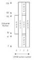
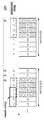
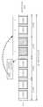
예를 들어, SSB 버스트 내의 4개의 슬롯에 대하여, SSB 전송이 가능한 SSB 인덱스가 #0~#7로 설정된다고 가정한다. 즉, 첫번째 슬롯의 전반부에 SSB_index=0, 후반부에 SSB_index=1이 설정될 수 있다. 마찬가지로, 두번째 슬롯의 전반부에 SSB_index=2, 후반부에 SSB_index=3이 설정될 수 있다. 순차적으로, 세번째 슬롯의 전반부에 SSB_index=4, 후반부에 SSB_index=5가 설정되고, 네번째 슬롯의 전반부에 SSB_index=6, 후반부에 SSB_index=7이 설정될 수 있다.For example, it is assumed that for 4 slots in an SSB burst, SSB indexes capable of SSB transmission are set to #0 to #7. That is, SSB_index=0 may be set in the first half of the first slot, and SSB_index=1 may be set in the second half of the first slot. Similarly, SSB_index=2 may be set in the first half of the second slot and SSB_index=3 may be set in the second half of the second slot. In sequence, SSB_index=4 and SSB_index=5 may be set in the first half of the third slot, SSB_index=6 may be set in the first half of the fourth slot, and SSB_index=7 may be set in the second half of the fourth slot.
예를 들어, 최초 설정에 따라, 첫번째 슬롯의 전반부에 SSB_index=0 및 세번째 슬롯의 전반부에 위치한 SSB_index=4에서 SSB가 전송되는 SSB 전송 패턴이 설정되어, 단말로 전송될 수 있다. 이 경우, 단말은 SSB_index=0 및 SSB_index=4에서 실제 동기 신호 검출 동작을 수행할 수 있다. 다만, 비면허 대역에서는 기지국이 실제 SSB 전송시에 LBT를 수행하고, LBT가 성공된 후 SSB 전송이 이루어지지 때문에, 최초 설정된 시점에서의 SSB 전송이 보장될 수 없다. 이에 따라, LBT 실패에 따른 SSB 전송 위치의 변경에 대한 정보를 포함하는 SSB 버스트 셋에서 SSB가 전송되는 전송 구간 정보가 단말로 전송될 수 있다.For example, according to the initial setting, an SSB transmission pattern in which the SSB is transmitted at SSB_index=0 in the first half of the first slot and SSB_index=4 in the first half of the third slot may be set and transmitted to the terminal. In this case, the UE may perform an actual synchronization signal detection operation at SSB_index=0 and SSB_index=4. However, in the unlicensed band, since the base station performs LBT during actual SSB transmission, and SSB transmission is not made after LBT is successful, SSB transmission at the initially set time cannot be guaranteed. Accordingly, in the SSB burst set including information on the change of the SSB transmission position according to the LBT failure, the information on the transmission period in which the SSB is transmitted may be transmitted to the terminal.
전송 구간 정보는 SSB 버스트 셋에서 LBT가 성공되어 SSB가 실제 전송되는 SSB 인덱스 정보를 포함할 수 있다. 이 경우, 일 예에 따라, SSB가 실제 전송되는 SSB 인덱스의 배치는 다수의 패턴으로 플렉시블하게 설정되고, 소정의 기준에 따라 선택된 패턴이 적용될 수 있다. 또는, 일 예에 따라, SSB가 실제 전송되는 SSB 인덱스가 RRC 시그널링 또는 RMSI를 통하여 지시될 수 있다.The transmission interval information may include SSB index information in which LBT is successful in the SSB burst set and the SSB is actually transmitted. In this case, according to an example, the arrangement of the SSB index to which the SSB is actually transmitted is flexibly set to a plurality of patterns, and a pattern selected according to a predetermined criterion may be applied. Alternatively, according to an example, the SSB index at which the SSB is actually transmitted may be indicated through RRC signaling or RMSI.
다른 일 예에 따라, SSB 버스트 셋에서 SSB가 전송되는 전송 구간 정보는, SSB 버스트 셋에서, LBT가 실패한 SSB 인덱스에서 전송되지 못한 SSB를 LBT가 성공한 SSB 인덱스에서 전송한 SSB 이후에 전송하도록 하는 사이클릭 패턴(cyclic pattern) 정보를 포함할 수 있다. 예를 들어, 상위 레이어 시그널링을 통해서 최최 설정된 SSB 전송 위치가 SSB index #0~#3이라고 가정한다. LBT가 SSB index #2에서 성공된 경우, SSB index #2~#5에서 SSB의 연속 전송이 수행될 수 있다.According to another example, the transmission interval information in which the SSB is transmitted in the SSB burst set is, in the SSB burst set, the SSB that is not transmitted in the SSB index in which the LBT fails, the SSB transmitted in the SSB index in which the LBT succeeds. It may include cyclic pattern information. For example, it is assumed that the most set SSB transmission positions through higher layer signaling are
이와 같이, SSB 전송 위치가 변경되는 경우, 이에 따른 SSB 전송을 위한 빔포밍 패턴의 적용이 다음과 같이 설정될 수 있다. 즉, NR에서는 gNB는 항상 정해진 시점에서 SSB를 전송할 수 있다. 따라서, SSB Burst set 내 각 SSB에 서로 상이한 빔포밍을 적용할 수 있으며, 다음 주기의 SSB burst set에서도 이러한 빔 적용이 반복되도록 설정할 수 있다. 그러나 NR-U에서는, LBT 이후 빔 전송이 수행되기 때문에, SSB가 항상 정해진 위치에서 전송되는 것을 보장하지 못한다. 따라서, NR-U에서는 SSB의 전송 시점을 항상 동일한 위치에서 전송하지 못하는 경우에 대한 빔 전송의 설정이 고려될 수 있다.In this way, when the SSB transmission position is changed, the application of the beamforming pattern for SSB transmission according to this may be set as follows. That is, in NR, the gNB can always transmit the SSB at a predetermined time. Accordingly, different beamforming can be applied to each SSB in the SSB burst set, and the beam application can be set to be repeated in the SSB burst set of the next cycle. However, in NR-U, since beam transmission is performed after LBT, it is not guaranteed that the SSB is always transmitted at a predetermined position. Therefore, in NR-U, the configuration of beam transmission for a case where the transmission time of the SSB cannot always be transmitted at the same position may be considered.
전술한 예에서, 최초 설정과 달리, SSB index #2~#5에서 SSB의 연속 전송이 수행되는 경우, #4, #5에서는 빔 설정이 되지 않아서 추가적인 설정이 필요하게 된다. 이에 따라, SSB 연속 전송 시에는 SSB burst 내 SSB들에 대해서 최초 설정된 빔 패턴에 대해서 사이클릭 패턴(cyclic pattern) 형태로 전체 SSB index들에 대해서 beam mapping을 수행할 수 있다. Cyclic pattern 형태는 미리 정의될 수 있으며, SSB burst내 실제 전송되는 SSB density를 고려해서 그 pattern이 결정될 수 있다. 예를 들어, SSB index #0, #1에 대하여 설정된 빔 패턴이 SSB index #4, #5에 대하여 적용될 수 있다.In the above-described example, unlike the initial configuration, when continuous transmission of the SSB is performed in
다른 일 예에 따라, SSB 버스트 셋에서 SSB가 전송되는 전송 구간 정보는, SSB 버스트 셋에서, SSB를 추가적으로 전송하는 SSB 인덱스를 나타내는 시프트(shift) 값 정보를 포함할 수 있다. 예를 들어, SSB 버스트 셋에 대하여, SSB가 전송되는 SSB 인덱스에 대한 단일 SSB indication information와 함께, 추가 shift 패턴을 고려한 N_shift 값이 추가로 지정될 수 있다. 예를 들어, 'N_shift' = 2이라는 값이 제공되면, 기존 위치에서 +2 이동된 패턴에 대한 SSB 검출을 시도할 수 있다. 이에 따라, 해당 위치에서 LBT가 성공하지 못하였을 경우, 바로 이어지는 구간에서의 LBT 성공 여부에 따라 SSB가 추가로 전송될 수 있는 기회가 제공될 수 있다.According to another example, the transmission period information in which the SSB is transmitted in the SSB burst set may include shift value information indicating an SSB index for additionally transmitting the SSB in the SSB burst set. For example, with respect to the SSB burst set, an N_shift value in consideration of an additional shift pattern may be additionally specified along with single SSB indication information for the SSB index through which the SSB is transmitted. For example, if a value of 'N_shift' = 2 is provided, SSB detection for a pattern shifted +2 from the existing position may be attempted. Accordingly, when the LBT is not successful at the corresponding location, an opportunity to additionally transmit the SSB may be provided depending on whether the LBT is successful in the immediately following section.
이 경우, RRC로 최초 전달된 SSB indication information이 N_shift = 2로 설정되면, 단말은 기본적으로 기존의 SSB indication information에 의한 SSB 검출 범위에 더해서, shift 패턴이 제공하는 SSB index까지 추가로 검출할 수 있다.In this case, if the SSB indication information first delivered to the RRC is set to N_shift = 2, the terminal basically in addition to the SSB detection range by the existing SSB indication information, up to the SSB index provided by the shift pattern can be additionally detected. .
다시 도 12를 참조하면, 단말은 전송 구간 정보에 기초하여 SSB 버스트 셋에서 SSB를 검출할 수 있다(S1220).Referring back to FIG. 12 , the UE may detect the SSB from the SSB burst set based on the transmission interval information ( S1220 ).
SSB 버스트 셋에서 SSB가 전송되는 SSB 인덱스를 포함하는 전송 구간 정보는, RRC 시그널링 또는 RMSI를 통하여 지시될 수 있다. 단말은 전송 구간 정보에 기초하여 SSB 버스트 셋에서 SSB가 전송되는 SSB 인덱스에 해당하는 슬롯에서 SSB를 검출할 수 있다. 즉, 단말은 LBT의 결과에 따라, 최초에 설정된 위치가 아닌 다른 위치에서도 SSB를 검출할 수 있다. 단말은 검출된 SSB에 기초하여, 동기를 획득하고, 시스템 정보를 업데이트할 수 있다. In the SSB burst set, the transmission interval information including the SSB index through which the SSB is transmitted may be indicated through RRC signaling or RMSI. The UE may detect the SSB in the slot corresponding to the SSB index through which the SSB is transmitted in the SSB burst set based on the transmission interval information. That is, according to the result of the LBT, the terminal may detect the SSB at a location other than the initially set location. The terminal may acquire synchronization based on the detected SSB and update system information.
이에 따르면, 비면허 대역에의 접속을 위한 동기 신호 블록의 전송 시, LBT 결과를 고려하여 동기 신호 블록의 송수신 복잡도를 최소화할 수 있는 비면허 대역에서 무선 통신을 수행하는 방법 및 장치를 제공할 수 있다. 또한, 비면허 대역에서 LBT 기반 빔포밍 패턴의 적용 및 빔 추정을 수행할 수 있는 구체적인 방법 및 장치를 제공할 수 있다.According to this, when transmitting the synchronization signal block for access to the unlicensed band, it is possible to provide a method and apparatus for performing wireless communication in an unlicensed band that can minimize the transmission/reception complexity of the synchronization signal block in consideration of the LBT result. In addition, it is possible to provide a specific method and apparatus capable of performing the application and beam estimation of the LBT-based beamforming pattern in the unlicensed band.
도 13은 일 실시예에 따른 기지국이 비면허 대역에서 무선 통신을 수행하는 절차를 도시한 도면이다.13 is a diagram illustrating a procedure for a base station to perform wireless communication in an unlicensed band according to an embodiment.
도 13을 참조하면, 기지국은 비면허 대역에서의 동기 신호 블록(Synchronization Signal Block; SSB) 버스트 셋(burst set)에 대한 설정 정보를 전송할 수 있다(S1300).Referring to FIG. 13 , the base station may transmit configuration information for a synchronization signal block (SSB) burst set in an unlicensed band (S1300).
SSB는 단일 형태가 아닌 SSB 버스트 셋(SSB burst set)으로 정의되어 전송된다. 기지국은 단말의 비면허 대역에서의 초기 접속 수행을 위하여, SSB를 전송하기 위한 SSB burst set에 대한 설정 정보를 전송할 수 있다. 해당 설정 정보는 SSB burst set의 주기 정보나 지속 구간 등에 대한 정보를 포함할 수 있다.The SSB is defined and transmitted as an SSB burst set rather than a single type. The base station may transmit configuration information for the SSB burst set for transmitting the SSB in order for the terminal to perform initial access in the unlicensed band. The corresponding configuration information may include information on period information or a duration period of the SSB burst set.
다시 도 13을 참조하면, 기지국은 비면허 대역에서의 SSB 버스트 셋에 대한 LBT(Listen Before Talk)를 수행할 수 있다(S1310).Referring back to FIG. 13 , the base station may perform Listen Before Talk (LBT) on the SSB burst set in the unlicensed band (S1310).
비면허 대역에서 임의의 노드에서 무선 신호를 송출하기 위해서는 다른 노드에 의해 해당 무선 채널이 점거(occupy)되고 있는지 여부를 확인하기 위한 LBT 과정을 거쳐야 한다. 이에 따라, 임의의 NR 기지국에 의해 구성된 비면허 대역의 NR-U 셀에서 SSB 전송을 위해서는, 해당 비면허 대역에 대한 LBT가 수행되어야 한다. LBT를 수행한 결과, 해당 비면허 대역의 무선 채널이 비어있는 경우, 기지국은 해당 비면허 대역의 무선 채널을 통하여 SSB를 전송할 수 있다.In order to transmit a radio signal from any node in the unlicensed band, it is necessary to go through an LBT process to check whether the corresponding radio channel is being occupied by another node. Accordingly, for SSB transmission in the NR-U cell of the unlicensed band configured by any NR base station, LBT for the unlicensed band must be performed. As a result of performing the LBT, if the radio channel of the unlicensed band is empty, the base station may transmit the SSB through the radio channel of the unlicensed band.
예를 들어, SSB 버스트 내의 4개의 슬롯에 대하여, SSB 전송이 가능한 SSB 인덱스가 #0~#7로 설정된다고 가정한다. 즉, 첫번째 슬롯의 전반부에 SSB_index=0, 후반부에 SSB_index=1이 설정될 수 있다. 마찬가지로, 두번째 슬롯의 전반부에 SSB_index=2, 후반부에 SSB_index=3이 설정될 수 있다. 순차적으로, 세번째 슬롯의 전반부에 SSB_index=4, 후반부에 SSB_index=5가 설정되고, 네번째 슬롯의 전반부에 SSB_index=6, 후반부에 SSB_index=7이 설정될 수 있다.For example, it is assumed that for 4 slots in an SSB burst, SSB indexes capable of SSB transmission are set to #0 to #7. That is, SSB_index=0 may be set in the first half of the first slot, and SSB_index=1 may be set in the second half of the first slot. Similarly, SSB_index=2 may be set in the first half of the second slot and SSB_index=3 may be set in the second half of the second slot. In sequence, SSB_index=4 and SSB_index=5 may be set in the first half of the third slot, SSB_index=6 may be set in the first half of the fourth slot, and SSB_index=7 may be set in the second half of the fourth slot.
예를 들어, 최초 설정에 따라, 첫번째 슬롯의 전반부에 SSB_index=0 및 세번째 슬롯의 전반부에 위치한 SSB_index=4에서 SSB가 전송되는 SSB 전송 패턴이 설정된 경우, 기지국은 SSB_index=0에 대한 LBT를 수행할 수 있다. LBT가 성공할 경우, 기지국은 최초 설정에 따라, 해당 비면허 대역에 대하여, SSB_index=0에서부터 정해진 패턴에 따라 SSB를 전송할 수 있다. 다만, LBT가 실패할 경우, 기지국은 최초 설정에 따른 SSB_index=0에서부터의 SSB 전송을 수행할 수 없게 된다.For example, according to the initial setting, if the SSB transmission pattern is set in which the SSB is transmitted at SSB_index=0 in the first half of the first slot and SSB_index=4 located in the first half of the third slot, the base station performs LBT for SSB_index=0. can When the LBT is successful, the base station may transmit the SSB according to a pattern determined from SSB_index=0 for the corresponding unlicensed band according to the initial setting. However, when the LBT fails, the base station cannot perform SSB transmission from SSB_index=0 according to the initial setting.
다시 도 13을 참조하면, 기지국은 LBT 결과에 기초한 SSB 버스트 셋에서 SSB가 전송되는 전송 구간 정보를 전송할 수 있다(S1320).Referring back to FIG. 13 , the base station may transmit information on a transmission period in which the SSB is transmitted in the SSB burst set based on the LBT result (S1320).
즉, 비면허 대역에서는 기지국이 실제 SSB 전송시에 LBT를 수행하고, LBT가 성공된 후 SSB 전송이 이루어지지 때문에, 최초 설정된 시점에서의 SSB 전송이 보장될 수 없다. 이에 따라, LBT 실패에 따른 SSB 전송 위치의 변경에 대한 정보를 포함하는 SSB 버스트 셋에서 SSB가 전송되는 전송 구간 정보가 단말로 전송될 수 있다.That is, in the unlicensed band, the base station performs LBT at the time of actual SSB transmission, and since SSB transmission is not made after LBT is successful, SSB transmission at the initially set time cannot be guaranteed. Accordingly, in the SSB burst set including information on the change of the SSB transmission position according to the LBT failure, the information on the transmission period in which the SSB is transmitted may be transmitted to the terminal.
전송 구간 정보는 SSB 버스트 셋에서 LBT가 성공되어 SSB가 실제 전송되는 SSB 인덱스 정보를 포함할 수 있다. 이 경우, 일 예에 따라, SSB가 실제 전송되는 SSB 인덱스의 배치는 다수의 패턴으로 플렉시블하게 설정되고, 소정의 기준에 따라 선택된 패턴이 적용될 수 있다. 또는, 일 예에 따라, SSB가 실제 전송되는 SSB 인덱스가 RRC 시그널링 또는 RMSI를 통하여 지시될 수 있다.The transmission interval information may include SSB index information in which LBT is successful in the SSB burst set and the SSB is actually transmitted. In this case, according to an example, the arrangement of the SSB index to which the SSB is actually transmitted is flexibly set to a plurality of patterns, and a pattern selected according to a predetermined criterion may be applied. Alternatively, according to an example, the SSB index at which the SSB is actually transmitted may be indicated through RRC signaling or RMSI.
다른 일 예에 따라, SSB 버스트 셋에서 SSB가 전송되는 전송 구간 정보는, SSB 버스트 셋에서, LBT가 실패한 SSB 인덱스에서 전송되지 못한 SSB를 LBT가 성공한 SSB 인덱스에서 전송한 SSB 이후에 전송하도록 하는 사이클릭 패턴(cyclic pattern) 정보를 포함할 수 있다. 예를 들어, 상위 레이어 시그널링을 통해서 최최 설정된 SSB 전송 위치가 SSB index #0~#3이라고 가정한다. LBT가 SSB index #2에서 성공된 경우, SSB index #2~#5에서 SSB의 연속 전송이 수행될 수 있다.According to another example, the transmission interval information in which the SSB is transmitted in the SSB burst set is, in the SSB burst set, the SSB that is not transmitted in the SSB index in which the LBT fails, the SSB transmitted in the SSB index in which the LBT succeeds. It may include cyclic pattern information. For example, it is assumed that the most set SSB transmission positions through higher layer signaling are
이와 같이, SSB 전송 위치가 변경되는 경우, 이에 따른 SSB 전송을 위한 빔포밍 패턴의 적용이 다음과 같이 설정될 수 있다. 즉, NR에서는 gNB는 항상 정해진 시점에서 SSB를 전송할 수 있다. 따라서, SSB Burst set 내 각 SSB에 서로 상이한 빔포밍을 적용할 수 있으며, 다음 주기의 SSB burst set에서도 이러한 빔 적용이 반복되도록 설정할 수 있다. 그러나 NR-U에서는, LBT 이후 빔 전송이 수행되기 때문에, SSB가 항상 정해진 위치에서 전송되는 것을 보장하지 못한다. 따라서, NR-U에서는 SSB의 전송 시점을 항상 동일한 위치에서 전송하지 못하는 경우에 대한 빔 전송의 설정이 고려될 수 있다.In this way, when the SSB transmission position is changed, the application of the beamforming pattern for SSB transmission according to this may be set as follows. That is, in NR, the gNB can always transmit the SSB at a predetermined time. Accordingly, different beamforming can be applied to each SSB in the SSB burst set, and the beam application can be set to be repeated in the SSB burst set of the next cycle. However, in NR-U, since beam transmission is performed after LBT, it is not guaranteed that the SSB is always transmitted at a predetermined position. Therefore, in NR-U, the configuration of beam transmission for a case where the transmission time of the SSB cannot always be transmitted at the same position may be considered.
전술한 예에서, 최초 설정과 달리, SSB index #2~#5에서 SSB의 연속 전송이 수행되는 경우, #4, #5에서는 빔 설정이 되지 않아서 추가적인 설정이 필요하게 된다. 이에 따라, SSB 연속 전송 시에는 SSB burst 내 SSB들에 대해서 최초 설정된 빔 패턴에 대해서 사이클릭 패턴(cyclic pattern) 형태로 전체 SSB index들에 대해서 beam mapping을 수행할 수 있다. Cyclic pattern 형태는 미리 정의될 수 있으며, SSB burst내 실제 전송되는 SSB density를 고려해서 그 pattern이 결정될 수 있다. 예를 들어, SSB index #0, #1에 대하여 설정된 빔 패턴이 SSB index #4, #5에 대하여 적용될 수 있다.In the above-described example, unlike the initial configuration, when continuous transmission of the SSB is performed in
다른 일 예에 따라, SSB 버스트 셋에서 SSB가 전송되는 전송 구간 정보는, SSB 버스트 셋에서, SSB를 추가적으로 전송하는 SSB 인덱스를 나타내는 시프트(shift) 값 정보를 포함할 수 있다. 예를 들어, SSB 버스트 셋에 대하여, SSB가 전송되는 SSB 인덱스에 대한 단일 SSB indication information와 함께, 추가 shift 패턴을 고려한 N_shift 값이 추가로 지정될 수 있다. 예를 들어, 'N_shift' = 2이라는 값이 제공되면, 기존 위치에서 +2 이동된 패턴에 대한 SSB 검출을 시도할 수 있다. 이에 따라, 해당 위치에서 LBT가 성공하지 못하였을 경우, 바로 이어지는 구간에서의 LBT 성공 여부에 따라 SSB가 추가로 전송될 수 있는 기회가 제공될 수 있다.According to another example, the transmission period information in which the SSB is transmitted in the SSB burst set may include shift value information indicating an SSB index for additionally transmitting the SSB in the SSB burst set. For example, with respect to the SSB burst set, an N_shift value in consideration of an additional shift pattern may be additionally specified along with single SSB indication information for the SSB index through which the SSB is transmitted. For example, if a value of 'N_shift' = 2 is provided, SSB detection for a pattern shifted +2 from the existing position may be attempted. Accordingly, when the LBT is not successful at the corresponding location, an opportunity to additionally transmit the SSB may be provided depending on whether the LBT is successful in the immediately following section.
이 경우, RRC로 최초 전달된 SSB indication information이 N_shift = 2로 설정되면, 단말은 기본적으로 기존의 SSB indication information에 의한 SSB 검출 범위에 더해서, shift 패턴이 제공하는 SSB index까지 추가로 검출할 수 있다.In this case, if the SSB indication information first delivered to the RRC is set to N_shift = 2, the terminal basically in addition to the SSB detection range by the existing SSB indication information, up to the SSB index provided by the shift pattern can be additionally detected. .
SSB 버스트 셋에서 SSB가 전송되는 SSB 인덱스를 포함하는 전송 구간 정보는, RRC 시그널링 또는 RMSI를 통하여 지시될 수 있다. 단말은 전송 구간 정보에 기초하여 SSB 버스트 셋에서 SSB가 전송되는 SSB 인덱스에 해당하는 슬롯에서 SSB를 검출할 수 있다. 즉, 단말은 LBT의 결과에 따라, 최초에 설정된 위치가 아닌 다른 위치에서도 SSB를 검출할 수 있다. 단말은 검출된 SSB에 기초하여, 동기를 획득하고, 시스템 정보를 업데이트할 수 있다.In the SSB burst set, the transmission interval information including the SSB index through which the SSB is transmitted may be indicated through RRC signaling or RMSI. The UE may detect the SSB in the slot corresponding to the SSB index through which the SSB is transmitted in the SSB burst set based on the transmission interval information. That is, according to the result of the LBT, the terminal may detect the SSB at a location other than the initially set location. The terminal may acquire synchronization based on the detected SSB and update system information.
이에 따르면, 비면허 대역에의 접속을 위한 동기 신호 블록의 전송 시, LBT 결과를 고려하여 동기 신호 블록의 송수신 복잡도를 최소화할 수 있는 비면허 대역에서 무선 통신을 수행하는 방법 및 장치를 제공할 수 있다. 또한, 비면허 대역에서 LBT 기반 빔포밍 패턴의 적용 및 빔 추정을 수행할 수 있는 구체적인 방법 및 장치를 제공할 수 있다.According to this, when transmitting the synchronization signal block for access to the unlicensed band, it is possible to provide a method and apparatus for performing wireless communication in an unlicensed band that can minimize the transmission/reception complexity of the synchronization signal block in consideration of the LBT result. In addition, it is possible to provide a specific method and apparatus capable of performing the application and beam estimation of the LBT-based beamforming pattern in the unlicensed band.
이하에서는, 관련도면을 참조하여, 비면허 대역(unlicensed band)에의 접속을 위한 동기 신호 블록을 전송하는 각 실시예에 대하여 구체적으로 설명하기로 한다.Hereinafter, each embodiment of transmitting a synchronization signal block for access to an unlicensed band will be described in detail with reference to the related drawings.
현재 NR에서는 비면허 대역 접속을 위한 'NR-based Access to Unlicensed Spectrum'이라는 Rel-16 Study Item을 진행하고 있다. NR-U를 위한 초기 액세스(initial access)와 관련하여, NR-U는 적어도 SS/PBCH 블록 버스트 셋(block burst set) 전송을 포함하는 신호를 가져야 한다.Currently, NR is conducting a Rel-16 Study Item called 'NR-based Access to Unlicensed Spectrum' for access to unlicensed bands. Regarding initial access for the NR-U, the NR-U must have a signal including at least SS/PBCH block burst set transmission.
초기 액세스 프로시저에 대한 다음의 수정 사항은 유용하다. LBT에 기초하여채널에 대한 액세스 제한을 고려한 초기 액세스 절차 수정으로, LBT 실패로 인해 감소된 SS/PBCH 블록 및 RMSI 전송 기회를 처리하는 기술을 개발할 필요가 있다. 또한, 4 스텝 RACH 향상으로, LBT 실패로 인해 감소된 msg 1/2/3/4 전송 기회를 처리하는 메커니즘이 필요할 수 있다. 또한, 2 스텝 RACH는 잠재적으로 채널 액세스에 이점을 갖는다.The following modifications to the initial access procedure are useful. Based on the LBT, it is necessary to develop a technique for handling the reduced SS/PBCH block and RMSI transmission opportunity due to LBT failure by modifying the initial access procedure in consideration of access restriction on the channel. Also, with the 4-step RACH enhancement, a mechanism may be needed to handle the reduced
본 개시에서는 NR의 SSB 전송 구조를 최대한 변경하지 않고 재사용할 수 있도록 하는 NR-U SSB 전송 구조를 제안한다. 기본적으로 NR-U에서는 WiFi 기기들과의 공존(coexistence)을 제공하기 위해서 LBT(listen before talk)를 수행한다. 즉, 비면허 대역에서 임의의 노드에서 무선 신호를 송출하기 위해서는 다른 노드에 의해 해당 무선 채널이 점거(occupy)되고 있는지 여부를 확인하기 위한 LBT 과정을 거쳐야 한다. 이에 따라, 임의의 NR 기지국에 의해 구성된 비면허 대역의 NR-U 셀에서 SSB 전송을 위해서는, 해당 비면허 대역에 대한 LBT가 수행되어야 한다. LBT를 수행한 결과, 해당 비면허 대역의 무선 채널이 비어있는 경우, 기지국은 해당 비면허 대역의 무선 채널을 통하여 SSB를 전송할 수 있다.The present disclosure proposes an NR-U SSB transmission structure that allows the NR SSB transmission structure to be reused without changing as much as possible. Basically, NR-U performs listen before talk (LBT) to provide coexistence with WiFi devices. That is, in order to transmit a radio signal from any node in the unlicensed band, it is necessary to go through an LBT process to check whether the radio channel is occupied by another node. Accordingly, for SSB transmission in the NR-U cell of the unlicensed band configured by any NR base station, LBT for the unlicensed band must be performed. As a result of performing the LBT, if the radio channel of the unlicensed band is empty, the base station may transmit the SSB through the radio channel of the unlicensed band.
따라서, 항상 정해진 시점에 전송되는 SSB가 NR-U의 stand-alone 모드에서는 원하는 슬롯에서는 전송되지 않을 수 있다. 단말은 최초 접속시 SSB와 RMSI를 수신함으로써 기본적인 초기 접속 모드를 수행하게 되지만, 동기 신호를 검출하지 못할 경우에는 셀 접속조차 불가능할 수 있다. 이하에서는 이와 관련하여 아래와 같은 실시예를 제안한다.Therefore, the SSB always transmitted at a predetermined time may not be transmitted in a desired slot in the stand-alone mode of NR-U. The terminal performs a basic initial access mode by receiving the SSB and the RMSI upon initial access, but when a synchronization signal is not detected, even cell access may not be possible. Hereinafter, in this regard, the following examples are proposed.
실시예 1. 다중(Multiple) SSB 전송 패턴 정보를 설정하여 SSB를 전송하고, 해당 정보를 단말에게 지시(indication)할 수 있다.
NR에서는 SSB 전송에 대해서 SSB 버스트 셋(SSB burst set)내 실제 전송이 이루어지는 SSB 인덱스(index)를 지시(indication)할 수 있다. SSB 인덱스의 지시는 비트맵으로 전송될 수 있다. 이를 위한 시그널링 모드로, 대기 모드(Idle mode)에서는 RMSI를 통하여 지시되고, 연결 모드(Connected mode)에서는 RRC를 통하여 지시될 수 있다.In NR, for SSB transmission, an SSB index at which actual transmission is performed in an SSB burst set may be indicated. The indication of the SSB index may be transmitted as a bitmap. As a signaling mode for this, it may be indicated through RMSI in idle mode, and may be indicated through RRC in connected mode.
예를 들어, 도 14와 같이, 15kHz SCS에서 SSB burst set 내의 SSB 수(L)가 8이라고 가정한다. 이 경우, 한 슬롯에서는 총 2번의 SSB가 전송될 수 있으므로, 4개의 슬롯에서 전체 SSB 전송 위치가 설정될 수 있다. 또한, 실제 SSB가 전송되는 위치는 gNB가 시그널링을 통해서 단말로 해당 정보를 지시해줄 수 있다.For example, as shown in FIG. 14 , it is assumed that the number of SSBs (L) in the SSB burst set is 8 in 15 kHz SCS. In this case, since a total of two SSBs can be transmitted in one slot, all SSB transmission positions can be set in four slots. In addition, the location where the actual SSB is transmitted may be indicated by the gNB to the terminal through signaling.
예를 들어, 단말이 비트맵 L=[10001000]을 수신했다고 가정한다. 해당 비트맵은 2비트가 하나의 슬롯에서의 SSB 전송 위치에 대응되므로, 4개의 슬롯 중 첫번째 슬롯의 전반부에 위치한 SSB_index=0 및 세번째 슬롯의 전반부에 위치한 SSB_index=4에서 SSB가 실제로 전송되는 것을 지시할 수 있다. 따라서, 단말은 SSB_index=0 및 SSB_index=4에서 실제 동기 신호 검출 동작을 수행할 수 있다. 기존 NR에서는 이러한 동작에 가능하지만, NR-U에서는 gNB가 실제 SSB 전송시에 LBT를 수행하고, LBT가 성공된 후 SSB 전송이 이루어지지 때문에 원래의 시점에서 SSB 전송을 보장할 수 없다.For example, it is assumed that the terminal has received the bitmap L=[10001000]. Since 2 bits correspond to the SSB transmission position in one slot, the corresponding bitmap indicates that the SSB is actually transmitted at SSB_index=0 located in the first half of the first slot and SSB_index=4 located in the first half of the third slot among the four slots. can do. Accordingly, the UE may perform an actual synchronization signal detection operation at SSB_index=0 and SSB_index=4. In the existing NR, this operation is possible, but in NR-U, the gNB performs LBT during actual SSB transmission, and SSB transmission is not performed after LBT is successful, so SSB transmission cannot be guaranteed at the original time point.
따라서, 일 예에 따라, NR-U를 위한 SSB 지시(indication) 필드를 다수 정의하고, 해당 정보를 단말로 지시할 수 있다. 예를 들어, 도 15와 같이, NR-U에서는 SSB burst set 내의 다수의 SSB 전송 패턴이 단말로 지시될 수 있다.Accordingly, according to an example, a plurality of SSB indication fields for NR-U may be defined and corresponding information may be indicated to the terminal. For example, as shown in FIG. 15 , in NR-U, multiple SSB transmission patterns in the SSB burst set may be indicated to the UE.
전술한 것과 같이, NR-U에서는 SSB 전송을 위해서 LBT를 수행한다. 따라서, 일 예에 따라, gNB는 SSB 지시 패턴(SSB indication pattern)-1에서 LBT를 실패한 경우, SSB indication pattern-2를 기반으로 LBT를 다시 수행할 수 있다. 즉, 도 15의 예에서, SSB_index #0, #4에서만 시도했던 LBT가 실패한 경우, SSB_index #2, #6에서 LBT를 수행할 수 있다.As described above, in NR-U, LBT is performed for SSB transmission. Therefore, according to an example, when the gNB fails the LBT in the SSB indication pattern-1, the gNB may perform the LBT again based on the SSB indication pattern-2. That is, in the example of FIG. 15, when the LBT attempted only at
결과적으로, 도 16과 같이, gNB는 단말에게 이미 Multiple SSB indication pattern을 설정하였기 때문에, SSB indication pattern-1을 기준으로 LBT를 수행하여 실패할 경우, SSB indication pattern-2로 스위칭(switching)하여 LBT를 바로 수행할 수 있다. LBT를 성공한 경우, 최초의 SSB indication pattern-1이 아닌 SSB indication pattern-2로 계속하여 SSB 전송을 수행할 수 있다. SSB indication pattern-2를 기준으로 LBT가 실패하여 SSB indication pattern-1으로 스위칭하는 반대의 경우에도 동일하게 동작하게 된다.As a result, as shown in FIG. 16 , since the gNB has already set the Multiple SSB indication pattern to the terminal, if it fails by performing LBT based on the SSB indication pattern-1, switching to the SSB indication pattern-2 (switching) LBT can be performed directly. If the LBT is successful, SSB transmission may be performed continuously with the SSB indication pattern-2 rather than the first SSB indication pattern-1. Based on the SSB indication pattern-2, the LBT fails and the reverse case of switching to the SSB indication pattern-1 will operate in the same way.
실시예 1-1. 단말은 다중 SSB 지시 패턴(Multiple SSB indication pattern)을 기반으로 SSB 검출을 성공한 패턴을 선택적으로 운용할 수 있다.Example 1-1. The terminal may selectively operate a pattern in which SSB detection is successful based on a multiple SSB indication pattern.
전술한 실시예 1에서와 같이, 단말은 시스템 정보를 토대로 다중 SSB indication pattern을 획득할 수 있다고 가정한다. 이 경우, gNB는 LBT 결과에 따라 SSB 지시 패턴을 스위칭할 수 있다. 이에 따라, 단말은 아래와 같이 SSB 검출을 수행할 수 있다.As in the above-described
일 예에 따라, 초기 액세스(initial access) 또는 SSB 지시 정보(indication information) 수신 전인 경우, 단말은 SSB burst set 내 SSB 전송 구간에 대해서 모두 SSB 검출을 수행할 수 있다. 따라서, 최초 SSB 검출의 복잡도가 가장 높게 된다. 이후, 단말은 SSB indication information에 따라 다중 SSB indication pattern에 대해서 SSB를 검출할 수 있다. 또한, 단말은 정상적으로 SSB가 검출된 최초 SSB index를 포함하는 SSB pattern을 가정하고 SSB 검출을 진행할 수 있다. 또한, 기존 SSB indication pattern 위치에서 SSB가 검출되지 않을 경우, 단말은 다른 패턴들에 대한 SSB 검출을 수행하고, 새롭게 검출된 SSB index가 포함된 SSB indication pattern으로 변경할 수 있다. 또한, 기본적으로 SSB indication pattern 각각에 포함되는 SSB index는 서로 중첩되지 않도록 설정될 수 있다. 다만, 이는 일 예로서, 이에 한정되는 것은 아니며, 일부 구간에서는 SSB index가 중첩될 수 있다.According to an example, before receiving initial access or SSB indication information, the UE may perform SSB detection for all SSB transmission periods in the SSB burst set. Therefore, the complexity of initial SSB detection becomes the highest. Thereafter, the terminal may detect the SSB for multiple SSB indication patterns according to the SSB indication information. In addition, the UE may perform SSB detection assuming the SSB pattern including the first SSB index in which the SSB is normally detected. In addition, if the SSB is not detected in the existing SSB indication pattern position, the terminal may perform SSB detection for other patterns, and change to the SSB indication pattern including the newly detected SSB index. In addition, basically, the SSB index included in each SSB indication pattern may be set so as not to overlap with each other. However, this is an example, and the present invention is not limited thereto, and SSB indexes may overlap in some sections.
다른 일 예에 따라, SSB 위치 변경의 경우, 기존 SSB indication pattern 위치에서 SSB가 검출되지 않을 경우에는 단말은 다른 패턴들에 대한 SSB 검출을 수행하고, 새롭게 검출된 SSB index가 포함된 SSB indication pattern으로 변경할 수 있다.According to another example, in the case of SSB location change, when the SSB is not detected in the existing SSB indication pattern location, the terminal performs SSB detection for other patterns, and as an SSB indication pattern including the newly detected SSB index. can be changed
실시예 1-2. gNB는 시그널링을 통해서 Multiple SSB indication pattern을 변경할 수 있다.Example 1-2. The gNB may change the Multiple SSB indication pattern through signaling.
일 예에 따라, SSB indication pattern에 대해서 RRC 정보를 설정하고, 단말에 전달할 수 있다. 기본적으로 gNB는 SSB indication pattern을 다수 개 설정할 수 있다. 다만, 처음부터 다중 SSB indication pattern을 이용하는 해당 모드로 동작하지 않을 수 있다. 예를 들어, 최초에는 기존 NR과 동일하게 단일 SSB indication information을 사용할 수 있다. 이후 LBT의 실패 수가 증가하여 SSB 전송에서 많은 기회를 얻을 수 없게 될 경우 해당 모드로 동작할 수 있다. 따라서, 이러한 경우에, 단말로 도 15와 같은 다중 SSB indication pattern 설정 정보를 지시할 수 있다. 이에 따른 다중 SSB indication pattern 정보를 정의하는 방법은 아래와 같이 구분될 수 있다.According to an example, RRC information may be set for the SSB indication pattern and delivered to the terminal. Basically, gNB can set a plurality of SSB indication patterns. However, it may not operate in the corresponding mode using multiple SSB indication patterns from the beginning. For example, initially, a single SSB indication information may be used in the same way as the existing NR. After that, when the number of failures in the LBT increases and many opportunities cannot be obtained in SSB transmission, it can operate in the corresponding mode. Therefore, in this case, it is possible to indicate multiple SSB indication pattern configuration information as shown in FIG. 15 to the terminal. A method of defining multiple SSB indication pattern information according to this can be divided as follows.
일 예에 따라, 다중 패턴들을 직접 정의하는 경우, gNB가 단말에게 전송해야 하는 비트맵 크기가 다중 패턴 수에 비례하여 증가되게 된다. 예를 들어, SSB burst set L=8에 대한 N개 패턴 지칭을 위해서 필요한 전체 정보(information) 수는 L x N이 된다. 이에 따른, 패턴 정보의 일 예는, Pattern-1: [10001000], Pattern-2: [01000100], Pattern-3: [00100010] 등과 같이 구성될 수 있다.According to an example, when multiple patterns are directly defined, the size of a bitmap that the gNB needs to transmit to the UE increases in proportion to the number of multiple patterns. For example, the total number of information required to designate N patterns for the SSB burst set L=8 becomes L x N. Accordingly, an example of the pattern information may be configured such as Pattern-1: [10001000], Pattern-2: [01000100], Pattern-3: [00100010].
다른 일 예에 따라, 오프셋(offset) 기반으로 다중 패턴들을 정의하는 경우, gNB가 정의한 최초 비트맵을 기준으로 패턴들 사이의 offset만을 단말에게 전송할 수 있다. 이 경우, 다중 패턴들을 직접 정의하는 경우에 비해서 정보 수가 감소할 수 있지만, SSB indication의 유연성(flexibility)은 감소하게 된다. 이에 따른, 패턴 정보의 일 예는, Pattern-1: [10001000], Pattern-2: offset=1 -> [01000100], Pattern-3: offset=2 -> [00100010] 등과 같이 구성될 수 있다.According to another example, when defining multiple patterns based on an offset, only the offset between the patterns based on the initial bitmap defined by the gNB may be transmitted to the UE. In this case, the number of information may be reduced compared to the case of directly defining multiple patterns, but the flexibility of the SSB indication will be reduced. Accordingly, an example of the pattern information may be configured as Pattern-1: [10001000], Pattern-2: offset=1 -> [01000100], Pattern-3: offset=2 -> [00100010].
실시예 2. gNB는 SSB indication pattern에 더해서 추가 검출 범위 정보를 단말에게 설정할 수 있다.
전술한 실시예 1에 따르면, gNB는 다중 SSB indication pattern 설정을 통해서 LBT가 실패하더라도 최대한 빠르게 SSB 전송을 수행할 수 있도록 LBT를 수행할 수 있는 기회를 제공할 수 있다. 또한, 실시예 1에서는, 다중 패턴에 대한 정보를 단말에게 전달하는 방법에 대해서도 전술하였다.According to the above-described
전술한 것과 달리, 실시예 2에서는 기존 NR과 동일하게 단일 SSB indication information/pattern을 제공할 수 있다. 이와 함께, SSB 검출과 관련된 범위 값을 추가로 지정할 수 있다. 예를 들어, 'N_add' = 1이라는 값이 제공되면, 기존 위치에서 +1 범위의 SSB index에 대하여, 단말이 SSB 검출을 시도할 수 있다. 이에 따라, 해당 위치에서 LBT가 성공하지 못하였을 경우, 바로 이어지는 구간에서 LBT 성공 여부에 따라 SSB가 추가로 전송될 수 있는 기회가 제공될 수 있다. 이때 설정되는 'N_add' 값은 + 방향, - 방향, ±방향 등으로 정의될 수 있다.Unlike the above, in
일 예에 따라, N_add 값이 양수(Positive value)이고, 기존 SSB indication information(L=8)는 [10001000] 인 경우를 가정한다. 예를 들어, N_add = +2로 설정되면, 도 17에 도시된 것과 같이, 단말이 검출해야 할 SSB index 범위와 관련, 최초 단말 검출 시도 SSB index은 [0,4]가 된다. 이후, N_add 값을 적용하면, [0, 1, 2, 4, 5, 6]의 SSB index에서 SSB 검출이 수행될 수 있다. 즉, 기존 SSB index를 포함하여 +2 구간에 위치한 SSB_index들이 새롭게 포함될 수 있다.According to an example, it is assumed that the N_add value is a positive number (Positive value), and the existing SSB indication information (L=8) is [10001000]. For example, when N_add = +2 is set, as shown in FIG. 17 , in relation to the range of the SSB index to be detected by the terminal, the first terminal detection attempt SSB index becomes [0,4]. Thereafter, when the N_add value is applied, SSB detection may be performed at the SSB index of [0, 1, 2, 4, 5, 6]. That is, including the existing SSB index, SSB_indexes located in the +2 section may be newly included.
다른 일 예에 따라, N_add 값이 음수(Negative value)이고, 기존 SSB indication information(L=8)는 [10001000] 인 경우를 가정한다. 예를 들어, N_add = -2로 설정되면, 도 18에 도시된 것과 같이, 단말이 검출해야 할 SSB index 범위와 관련, 최초 단말 검출 시도 SSB index은 [0,4]가 된다. 이후, N_add 값을 적용하면, [6, 7, 0, 2, 3, 4]의 SSB index에서 SSB 검출이 수행될 수 있다. 즉, 기존 SSB index를 포함하여 -2 구간에 위치한 SSB_index들이 새롭게 포함될 수 있다.According to another example, it is assumed that the N_add value is a negative number (Negative value), and the existing SSB indication information (L=8) is [10001000]. For example, when N_add = -2 is set, as shown in FIG. 18 , in relation to the range of the SSB index to be detected by the terminal, the first terminal detection attempt SSB index becomes [0,4]. Thereafter, when the N_add value is applied, SSB detection may be performed at the SSB index of [6, 7, 0, 2, 3, 4]. That is, including the existing SSB index, SSB_indexes located in the -2 section may be newly included.
또 다른 일 예에 따라, N_add 값이 양수 및 음수(Positive + Negative value)이고, 기존 SSB indication information(L=8)는 [10001000] 인 경우를 가정한다. 예를 들어, N_add = ±1로 설정되면, 도 19에 도시된 것과 같이, 단말이 검출해야 할 SSB index 범위와 관련, 최초 단말 검출 시도 SSB index은 [0,4]가 된다. 이후, N_add 값을 적용하면, [7, 0, 1, 3, 4, 5]의 SSB index에서 SSB 검출이 수행될 수 있다. 즉, 기존 SSB index를 포함하여 ±1 구간에 위치한 SSB_index들이 새롭게 포함될 수 있다.According to another example, it is assumed that the N_add value is positive and negative (Positive + Negative value), and the existing SSB indication information (L=8) is [10001000]. For example, when N_add = ±1 is set, as shown in FIG. 19 , in relation to the range of the SSB index to be detected by the terminal, the first terminal detection attempt SSB index becomes [0,4]. Thereafter, when the N_add value is applied, SSB detection may be performed at the SSB index of [7, 0, 1, 3, 4, 5]. That is, SSB_indexes located in the ±1 section including the existing SSB index may be newly included.
실시예 3. gNB는 LBT 성공 후 최초 SSB indication field의 시간 밀도(time density)만큼 SSB를 연속적으로 전달할 수 있다.Example 3. gNB may continuously deliver the SSB as much as the time density (time density) of the first SSB indication field after LBT success.
실시예 3에서는 앞서 언급한 SSB indication에 대해서 연속적인 수행을 가정한다. 즉, 기존 NR과 동일하게 gNB는 단말에게 실제 Burst set 내 실제 SSB가 전송되는 정보인 SSB indication 정보를 단말로 전달할 수 있다. 이 경우, gNB는 정해진 위치에 대해 LBT 결과에 따라 SSB 전송 여부가 결정되게 된다. 따라서, 다음 시점에서 SSB 전송이 불가능할 수도 있기 때문에, LBT가 성공한 시점에서 기존의 time density에 해당하는 만큼 연속적인 SSB 전송이 수행될 수 있다. 이를 통해서, 단말에게 보다 정확한 SSB 전송이 가능하게 된다. 이때, 단말이 연속적으로 전송하는 SSB 수는 SSB burst set 내 SSB 수와 동일할 수 있다. 즉, 자신의 전송 위치에서 전송되지 않더라도 연속적인 전송을 할 수 있게 되는데, 도 20과 같이, LBT가 성공한 시점을 기준으로 그룹별(Group-wise) 또는 연속적인(consecutive) 전송이 이루어질 수 있다.In Example 3, it is assumed that continuous performance is performed for the aforementioned SSB indication. That is, like the existing NR, the gNB may deliver SSB indication information, which is information that the actual SSB is transmitted in the actual burst set, to the terminal to the terminal. In this case, whether the gNB transmits the SSB is determined according to the LBT result for the determined location. Therefore, since SSB transmission may not be possible at the next time point, continuous SSB transmission may be performed as much as the existing time density at the time LBT is successful. Through this, more accurate SSB transmission to the terminal is possible. In this case, the number of SSBs continuously transmitted by the UE may be the same as the number of SSBs in the SSB burst set. That is, even if it is not transmitted in its own transmission position, continuous transmission is possible. As shown in FIG. 20, group-wise or continuous transmission can be made based on the time when LBT is successful.
이 경우, gNB 측면에서 LBT에 성공한 SSB index를 중심으로 연속적인 전송을 수행하고, 다음 차례의 SSB index는 전송을 생략할 수 있다. gNB는 첫번째 SSB index 지점에서 LBT가 실패하면, 다음 SSB index 시점에서 다시 한번 LBT 수행한 후 시간 밀도만큼 연속하여 전송할 수 있다.In this case, continuous transmission is performed based on the SSB index that has succeeded in LBT from the gNB side, and the transmission of the next SSB index may be omitted. If the LBT fails at the first SSB index point, the gNB may perform LBT once again at the next SSB index point and then transmit continuously as much as the time density.
단말 측면에서 SSB indication field 의 전송 포인트에서 연속적인 SSB 검출을 수행할 수 있다. 단말은 SSB indication information을 기반으로 실제 SSB가 전송되는 index를 기준으로 N개의 SSB 연속 전송을 가정하고 검출을 수행할 수 있다.In the terminal side, it is possible to perform continuous SSB detection at the transmission point of the SSB indication field. The UE may perform detection on the assumption that N number of SSBs are continuously transmitted based on the index at which the actual SSB is transmitted based on the SSB indication information.
실시예 4. SSB 전송 시 시프트 패턴(shift pattern)을 적용할 수 있다.
실시예 4에서는 전술한 것과 달리, 기존 NR과 동일하게 단일 SSB indication information을 제공할 수 있다. 이와 함께, 추가 shift 패턴을 고려한 N_shift 값을 추가로 지정할 수 있다. 예를 들어, 'N_shift' = 2이라는 값이 제공되면, 기존 위치에서 +2 이동된 패턴에 대한 SSB 검출을 시도할 수 있다. 이에 따라, 해당 위치에서 LBT가 성공하지 못하였을 경우, 바로 이어지는 구간에서 LBT 성공 여부에 따라 SSB가 추가로 전송될 수 있는 기회가 제공될 수 있다. 이때 설정되는 'N_shift' 값은 단일 값으로 결정되거나 여러 셋으로 설정하여 정의될 수 있다. 즉, 일 예에 따라, N_shift = {a0}과 같이, 단일 shift value를 제공할 수 있다. 또는 다른 일 예에 따라, N_shift = {a0, a1, a2, ...}과 같이, 다중 shift value set을 제공할 수 있다.In Example 4, unlike the above, a single SSB indication information may be provided in the same way as the existing NR. In addition, an N_shift value in consideration of the additional shift pattern can be additionally specified. For example, if a value of 'N_shift' = 2 is provided, SSB detection for a pattern shifted +2 from the existing position may be attempted. Accordingly, when LBT is not successful at the corresponding location, an opportunity to additionally transmit the SSB may be provided according to the success or failure of the LBT in the immediately following section. In this case, the set 'N_shift' value may be determined as a single value or may be defined by setting multiple sets. That is, according to an example, as N_shift = {a0 }, a single shift value may be provided. Alternatively, according to another example, multiple shift value sets may be provided asN_shift = {a 0 , a1 , a2 , ...}.
도 21을 참조하면, RRC로 최초 전달된 SSB indication information이 N_shift = 2로 설정된 경우, 또 다른 SSB 전송 기회를 갖는 예가 도시되어 있다. 이 경우, 단말은 기본적으로 기존의 SSB indication information에 의한 SSB 검출 범위에 더해서, shift 패턴이 제공하는 SSB index까지 추가로 검출해야 함을 알 수 있다.Referring to Figure 21, when the SSB indication information initially delivered to the RRC is set to N_shift = 2, an example having another SSB transmission opportunity is shown. In this case, it can be seen that the terminal basically needs to additionally detect the SSB index provided by the shift pattern in addition to the SSB detection range by the existing SSB indication information.
이에 따르면, 비면허 대역에의 접속을 위한 동기 신호 블록의 전송 시, LBT 결과를 고려하여 동기 신호 블록의 송수신 복잡도를 최소화할 수 있는 비면허 대역에서 무선 통신을 수행하는 방법 및 장치를 제공할 수 있다.According to this, when transmitting the synchronization signal block for access to the unlicensed band, it is possible to provide a method and apparatus for performing wireless communication in an unlicensed band that can minimize the transmission/reception complexity of the synchronization signal block in consideration of the LBT result.
이하에서는, 전술한 NR-U의 SSB/CSI-RS 전송 구조 변경에 따른 빔 매니지먼트(Beam management) 방법에 대해서 설명하기로 한다. NR에서 Beam management를 위해서, 레퍼런스 참조신호(Reference RS)와 타겟 참조신호(Target RS) 사이에 빔을 지시(indication)하기 위한 전송 구성 지시자(Transmission configuration indicator; TCI)가 도입되었다.Hereinafter, a beam management method according to the change of the SSB/CSI-RS transmission structure of the aforementioned NR-U will be described. For beam management in NR, a transmission configuration indicator (TCI) for indicating a beam between a reference reference signal (Reference RS) and a target reference signal (Target RS) has been introduced.
이는, 데이터 채널 추정 및 CSI 추정을 위해 쓰이는 참조신호(RS)를 위해서 빔 페어링(pairing) 정보를 제공하는 것을 의미할 수 있다. 또한, TRP와 단말 사이의 빔 pairing 여부도 포함될 수 있다. RS 사이에 빔 pairing을 위해서 쓰이는 Quasi co-location(QCL) 정보를 단말에게 알려주도록 되어 있다. QCL 타입은 결과적으로 아래와 같이, 두 RS 사이에 채널 유사성 정도를 구분하는 단계를 의미할 수 있다.This may mean providing beam pairing information for a reference signal (RS) used for data channel estimation and CSI estimation. In addition, whether beam pairing between the TRP and the terminal may be included. It is designed to inform the UE of quasi co-location (QCL) information used for beam pairing between RSs. As a result, the QCL type may mean a step of discriminating the degree of channel similarity between two RSs as follows.
Quasi co-location (QCL) Type과 관련된 채널 유사성은, QCL Type A에서 {Doppler shift, Doppler spread, average delay, delay spread}, QCL Type B에서 {Doppler shift, Doppler spread}, QCL Type C에서 {average delay, Doppler shift}, QCL Type D에서 {Spatial Rx parameter}로 구분될 수 있다.Channel similarity related to quasi co-location (QCL) Type is {Doppler shift, Doppler spread, average delay, delay spread} in QCL Type A, {Doppler shift, Doppler spread} in QCL Type B, {average in QCL Type C delay, Doppler shift}, can be classified as {Spatial Rx parameter} in QCL Type D.
즉, NR에서는 빔 추정을 위해서 L1-RSRP를 도입하였다. 전술한 바와 같이, L1-RSRP는 SSB 와 CSI-RS를 통해서 이루어지는데, NR-U에서는 두 RS의 전송이 LBT 성공 유무에 따라 전송이 결정된다.That is, in NR, L1-RSRP was introduced for beam estimation. As described above, L1-RSRP is performed through SSB and CSI-RS. In NR-U, transmission of two RSs is determined according to LBT success or not.
따라서, 이하에서는 이러한 NR-U beam management 특성을 고려할 경우, SSB/CSI-RS의 전송 여부에 따른 beam pairing 결정 방법과 단말의 빔 추정 방법에 대해서 설명한다. 이하에서는, SSB를 중심으로 설명하나, CSI-RS의 경우에도 실질적으로 동일하게 적용될 수 있다.Accordingly, a description will be given of a method of determining beam pairing according to whether SSB/CSI-RS is transmitted and a method of estimating a beam of a UE in consideration of such NR-U beam management characteristics. Hereinafter, the SSB will be mainly described, but substantially the same may be applied to the CSI-RS.
실시예 5. 빔 추정을 위한 SSB/CSI-RS 전송시에서는 LBT 성공 시점에서 N개의 연속적인 SSB/CSI-RS 전송을 수행할 수 있다.
실시예 5에서는 빔 추정을 위한 SSB/CSI-RS 전송 시, 연속적인 전송을 제안한다. 이것은 일반적인 SSB 전송이나, CSI 추정을 위한 CSI-RS 전송과는 조금 다른 프로시저를 의미한다. 즉, gNB와 단말 사이에 빔 pairing을 위해서 기본적으로 수행하는 프로시저이며, gNB에서는 최적의 전송 빔을 찾기 위해서 SSB 또는 CSI-RS 자원(resource)들에 서로 다른 방향성 빔을 설정할 수 있다. 이 경우, 단말은 설정된 SSB 또는 CSI-RS 전송 주기에 맞춰, 정해진 위치에서 수신한 SSB index 또는 CSI-RS resource index를 기반으로 추정된 L1-RSRP 값을 도출할 수 있다. 따라서, 실시예 5에서는 NR-U의 특성을 고려하여, 빔 스위핑(beam sweeping), 빔 개선(beam refinement) 단계를 포함하여, beam management 단계에서 SSB 또는 CSI-RS 전송 시에 연속적인 전송 모드가 도입될 수 있다.In
기본적으로, 도 20과 같이, SSB는 LBT 성공 시점부터 연속적인 SSB 전송이 수행될 수 있다. 여기에서, SSB의 SSB burst 내 전송 밀도(density)는 4/8로 동일하다고 가정한다. 기존 NR에서는 SSB burst 내 어느 위치에서도 SSB 전송을 수행하지만, 본 실시예에서는 LBT 성공 시점에서 동일한 SSB 전송 density를 유지하면서 SSB 전송을 수행할 수 있다. 일 예에 따라, SSB 전송 density에 대해서는 'NSSB_TX'를 별도로 지정할 수 있으며, 기존의 동기 신호 설정을 위해 설정된 값과 다를 수 있다. 해당 값은 상위 레이어 시그널링을 통해서 단말로 전송될 수 있다.Basically, as shown in Figure 20, the SSB may be continuously transmitted SSB from the LBT success point. Here, it is assumed that the transmission density in the SSB burst of the SSB is equal to 4/8. In the existing NR, SSB transmission is performed at any position within the SSB burst, but in this embodiment, SSB transmission can be performed while maintaining the same SSB transmission density at the time of LBT success. According to an example, 'NSSB_TX ' may be separately specified for the SSB transmission density, and may be different from a value set for the existing synchronization signal setting. The corresponding value may be transmitted to the terminal through higher layer signaling.
동일한 원리로 CSI-RS 전송도, 설정된 전송 주기에 관계없이 CSI-RS resource 수만큼 시간 영역에서 연속적인 전송을 지원할 수 있다. 예를 들어, 도 22와 같이, 전체 4개의 CSI-RS resource들이 설정되었다고 가정한다. 이 경우, LBT가 성공한 이후, 빔 제어를 위한 CSI-RS 전송은 도시된 것과 같이, 연속적인 전송이 수행될 수 있다. 즉, CSI-RS resource들의 전송 주기 및 전송 위치(time offset)에 관계 없이, LBT 성공 이후 연속적인 CSI-RS 전송을 수행하는 것을 의미할 수 있다. 여기에서, CSI-RS resource 별 시간 영역 전송 위치는 슬롯 단위로 매핑(mapping)하거나, 슬롯 내에 'NX'개의 CSI-RS resource들을 위치시킬 수 있다. 도 22에서는 슬롯 내에 Nx=2개의 CSI-RS resource들이 연속적으로 전송되는 배치가 도시되어 있다.In the same principle, CSI-RS transmission may support continuous transmission in the time domain as many as the number of CSI-RS resources regardless of the configured transmission period. For example, as shown in FIG. 22, it is assumed that all four CSI-RS resources are configured. In this case, after LBT is successful, CSI-RS transmission for beam control may be continuously transmitted as shown. That is, regardless of the transmission period and transmission position (time offset) of the CSI-RS resources, it may mean to perform continuous CSI-RS transmission after LBT success. Here, the time domain transmission position for each CSI-RS resource may be mapped in units of slots, or 'NX ' CSI-RS resources may be located in the slot. 22 shows an arrangement in which Nx=2 CSI-RS resources are continuously transmitted in a slot.
실시예 5-1. LBT 결과에 따라 SSB 전송 위치가 변경되면, 변경된 시점의 SSB index부터 빔포밍 패턴이 적용될 수 있다.Example 5-1. When the SSB transmission position is changed according to the LBT result, the beamforming pattern may be applied from the SSB index of the changed time point.
기존 NR에서는 gNB는 항상 정해진 시점에서 SSB를 전송할 수 있다. 따라서, SSB Burst set 내 각 SSB에 서로 상이한 빔포밍을 적용할 수 있으며, 다음 주기의 SSB burst set에서도 이러한 빔 적용이 반복되도록 설정할 수 있다. 그러나 NR-U에서는, LBT 이후 빔 전송이 수행되기 때문에, SSB가 항상 정해진 위치에서 전송되는 것을 보장하지 못한다. 따라서, NR-U에서는 SSB의 전송 시점을 항상 동일한 위치에서 전송하지 못하는 경우에 대해, 다음과 같은 빔 전송이 고려될 수 있다.In the existing NR, the gNB can always transmit the SSB at a predetermined time. Accordingly, different beamforming can be applied to each SSB in the SSB burst set, and the beam application can be set to be repeated in the SSB burst set of the next cycle. However, in NR-U, since beam transmission is performed after LBT, it is not guaranteed that the SSB is always transmitted at a predetermined position. Therefore, in NR-U, the following beam transmission may be considered for a case where the transmission time of the SSB cannot always be transmitted at the same position.
최초에 NR-U 단말에게 SSB index #0~3까지 4개의 SSB 전송 정보를 설정했다고 가정한다. 그러나 도 23에서와 같이, 다음 SSB burst #N 내에서는 LBT가 SSB index #0 시점에서 성공하지 못한 경우, 추가적으로 수행한 LBT가 성공한 SSB #2에서부터 SSB #5까지 4개 SSB 전송을 수행할 수 있다. 이 경우, 빔 추정을 위해서는 SSB별 L1-RSRP를 추정해야 하며, beam measurement를 수행한 SSB index가 해당 빔의 정보를 가리키는 index가 될 수 있다.It is assumed that four SSB transmission information from
즉, 상위 레이어 시그널링을 통해서 단말에 전송한 SSB 전송 시그널링은 L='11110000'이지만, 실제 SSB가 전송된 것은 L'='00111100'이 된다. 이 경우, SSB Burst 내 SSB index별 빔 정보는 SSB burst #N에서 업데이트 되어야 하지만, Beam P0가 SSB #0와 SSB #2에서 전송되기 때문에 빔 업데이트 및 빔 추정에 오류가 발생할 수 있다.That is, the SSB transmission signaling transmitted to the UE through higher layer signaling is L='11110000', but the actual SSB transmission is L'='00111100'. In this case, beam information for each SSB index in the SSB burst should be updated in SSB burst #N, but since Beam P0 is transmitted in
따라서, 본 실시예에서는 전술한 도 23과 같은 LBT 기반 SSB 전송 방법은 유지하되, 단말에게는 최초 상위 레이어 시그널링으로 설정한 SSB #0~3시점에 맞춰 항상 빔이 설정된다고 가정할 수 있다. 즉, LBT에 따라서 SSB 전송 시점이 변경된다면, 실제 SSB를 전송한 위치(SSB #2)는 다르지만 해당 빔 정보를 SSB #0와 같다고 가정할 수 있다. 예를 들어, LBT를 최초 위치에서 성공하여 SSB index #0에서 빔 P1이 설정되어 전송되었고, 다음 SSB burst #N의 SSB index #2에서 LBT가 성공한 경우에는 SSB index #2에서 빔 P1이 전송되었다고 가정한다. 따라서, 단말은 SSB busrt #0내 SSB #0의 빔 추정 값을 단말은 SSB busrt #N내 SSB #2의 빔 추정 값으로 업데이트할 수 있다. 이때, 단말이 gNB에게 리포팅하는 값은 최초 설정 값인 SSB index #0가 된다.Therefore, in this embodiment, while maintaining the LBT-based SSB transmission method as in FIG. 23 described above, it can be assumed that the beam is always set in accordance with the
실시예 5-2. LBT 결과에 따라 SSB 전송 위치가 변경되면, 사이클릭 패턴(cyclic pattern) 기반으로 다음 SSB index 빔포밍 패턴을 적용할 수 있다.Example 5-2. When the SSB transmission position is changed according to the LBT result, the following SSB index beamforming pattern may be applied based on a cyclic pattern.
본 실시예에서는 전술한 실시예 5-1과 달리, SSB index 별로 최초 설정된 빔포밍이 동일하게 적용될 수 있다. 그러나 최초 설정과 달리, LBT에 따라 SSB를 정해진 위치에서 전송하지 않는 경우, 새롭게 전송 영역으로 포함된 SSB index들의 beam mapping은 cyclic pattern 기반으로 적용될 수 있다. 예를 들어, 도 24와 같이, 최초 상위 레이어 시그널링을 통해서 설정된 SSB 전송 위치는 #0~#3이 된다. 그러나, LBT의 결과에 따라 SSB index #2에서 동기 신호 전송을 수행한다고 가정한다. 이때 #4, #5에서는 빔 설정이 되지 않아서 추가적인 설정이 필요하게 된다. 본 실시예에 따르면, SSB 연속 전송 시에는 SSB burst 내 SSB들에 대해서 최초 설정된 빔 패턴에 대해서 cyclic pattern 형태로 전체 SSB index들에 대해서 beam mapping을 수행할 수 있다. Cyclic pattern 형태는 미리 정의될 수 있으며, SSB burst내 실제 전송되는 SSB density를 고려해서 그 pattern이 결정될 수 있다.In this embodiment, unlike the aforementioned embodiment 5-1, beamforming initially set for each SSB index may be equally applied. However, unlike the initial configuration, when the SSB is not transmitted at a predetermined position according to the LBT, beam mapping of the SSB indexes newly included in the transmission area may be applied based on a cyclic pattern. For example, as shown in FIG. 24 , the SSB transmission positions set through the first higher layer signaling are #0 to #3. However, it is assumed that synchronization signal transmission is performed at
실시예 6. 빔 추정을 위한 SSB/CSI-RS가 LBT 성공 시점에서 N개의 연속적인 SSB/CSI-RS 전송을 수행할 경우 단말은 SSB/CSI-RS 최초 수신 시점을 참조(reference) 시점으로 가정할 수 있다.Example 6. When the SSB/CSI-RS for beam estimation performs N consecutive SSB/CSI-RS transmissions at the LBT success time, the UE assumes the SSB/CSI-RS initial reception time as a reference time. can do.
전술한 실시예 5에서는 빔 제어 및 추정을 위해서 연속적인 SSB/CSI-RS 전송을 기반으로 빔 설정 방법에 대해서 설명하였다. 본 실시예에서는 빔 추정을 위한 단말의 동작에 대해서 설명한다. 우선, 전술한 것과 같이, NR-U에서는 LBT의 성공 유무에 따라서 가장 기본적인 동기 신호인 SSB전송도 결정된다. 따라서, beam management를 위한 기본 프로시저인 beam sweeping, beam refinement 단계를 위해서는 앞서 설정된 빔에 대한 전송이 필요하게 된다.In the above-described
NR에서는 상위 레이어 시그널링을 통해서 SSB 와 CSI-RS의 자원 배치 및 전송 주기를 설정할 수 있다. 그러나 NR-U에서는 이러한 설정 구조를 그대로 도입하더라도 원하는 시기에 LBT를 성공하지 못하면 해당 신호에 대한 전송이 불가능하게 된다. 결과적으로, 연속적인 신호 전송을 기반으로 beam management 프로시저를 도입하는 것이 필요하게 된다. 여기에서, gNB는 특정 위치에서 상이한 빔 설정을 한 SSB/CSI-RS 전송을 수행할 수 있다. 이 경우, 단말은 이러한 SSB/CSI-RS에 대한 수신 위치 및 빔 정보 업데이트에 대한 참조점(reference point)을 가정할 수 있다. 결과적으로, 본 실시예에 따르면, SSB/CSI-RS 수신을 한 위치에 대한 reference point 적용과 미적용 두 가지 모드에 대한 단말 동작이 지정될 수 있다.In NR, resource allocation and transmission period of SSB and CSI-RS may be configured through higher layer signaling. However, in NR-U, even if such a configuration structure is introduced as it is, if LBT is not successful at the desired time, transmission of the corresponding signal becomes impossible. As a result, it becomes necessary to introduce a beam management procedure based on continuous signal transmission. Here, the gNB may perform SSB/CSI-RS transmission with different beam configuration at a specific location. In this case, the UE may assume a reference point for updating the reception location and beam information for the SSB/CSI-RS. As a result, according to the present embodiment, the terminal operation for two modes of application and non-applied reference point to a location where SSB/CSI-RS is received may be designated.
실시예 6-1. 단말의 SSB/CSI-RS기반 L1-RSRP 도출에 대한 Reference point의 적용Example 6-1. Application of the reference point for the SSB/CSI-RS-based L1-RSRP derivation of the terminal
본 실시예의 reference point는 SSB/CSI-RS 전송 시에 최초 상위 레이어 시그널링으로 정의된 SSB/CSI-RS 전송 포인트(특히 시간축 위치)를 의미할 수 있다. 전술한 것과 같이, 최초 SSB Burst 내 특정 SSB index들을 상위 레이어 시그널링으로 설정한 경우, 단말은 SSB가 해당 SSB index에서 전송될 것이라고 가정하고, SSB 수신을 수행할 수 있다. 따라서, 최초 설정된 SSB indication 필드는 reference point가 된다.The reference point in this embodiment may mean an SSB/CSI-RS transmission point (particularly a time axis position) defined as the first upper layer signaling during SSB/CSI-RS transmission. As described above, when specific SSB indices in the initial SSB burst are set as higher layer signaling, the UE may perform SSB reception assuming that the SSB will be transmitted in the corresponding SSB index. Therefore, the initially set SSB indication field becomes a reference point.
이 경우, reference point에 대한 빔 추정 결과를 도출 또는 업데이트 함에 있어서, 그 위치가 다른 곳에서 추정된 SSB/CSI-RS이더라도 최초 설정된 SSB/CSI-RS resource 영역에 빔 정보 즉 L1-RSRP 값을 업데이트할 수 있다. 즉, 단말은 L1-RSRP 값이 다른 SSB index/CSI-RS resource index에서 도출되었더라도 최초 설정된 SSB index 또는 CSI-RS resource index 값을 가지고 빔 추정 값 또는 L1-RSRP를 업데이트할 수 있다.In this case, in deriving or updating the beam estimation result for the reference point, even if the location is the SSB/CSI-RS estimated elsewhere, the beam information, that is, the L1-RSRP value is updated in the initially set SSB/CSI-RS resource area. can do. That is, the UE may update the beam estimation value or L1-RSRP with the initially set SSB index or CSI-RS resource index value even if the L1-RSRP value is derived from another SSB index/CSI-RS resource index.
예를 들어, 도 25와 같이, 최초 설정된 SSB burst 내 실제 전송이 이루어지는 SSB들에 대해 최초 설정된 indication 필드를 reference point로 지정할 수 있다. NR-U에서 첫번째 전송에서는 정상적인 위치에서 LBT가 성공하여 reference point와 동일한 SSB 전송을 수행하였다고 가정한다. 두번째 SSB 전송에서는 LBT가 reference point보다 늦은 시점에서 성공하여 SSB index #2번 위치부터 전송을 수행한다고 가정한다. 이 경우, 실제 단말은 SSB가 전송되는 구간의 빔 세팅은 각각 도 25와 같다고 가정한다. 따라서, 단말은 2번째 SSB 전송 구간의 SSB index #2에서 추정한 빔 정보 또는 추정 값을 reference point인 SSB index #0에 업데이트할 수 있다. SSB index #3~5의 경우에도 마찬가지로 동일한 원리를 적용하여 reference point의 SSB index #1-3에 업데이트할 수 있다. 이를 통해서, gNB는 단말이 리포팅한 값을 토대로 해당 단말의 빔 정보를 정확하게 획득할 수 있다. 전술한 설명은 CSI-RS의 경우에도 실질적으로 동일하게 적용될 수 있다.For example, as shown in FIG. 25, an indication field initially configured for SSBs in which actual transmission is made within the initially configured SSB burst may be designated as a reference point. In the first transmission in NR-U, it is assumed that LBT succeeds in a normal position and the same SSB transmission as the reference point is performed. In the second SSB transmission, it is assumed that the LBT succeeds at a later time than the reference point and the transmission is performed from the
실시예 6-2. 단말의 SSB/CSI-RS기반 L1-RSRP 도출에 대한 Reference point의 미적용Example 6-2. Non-applied reference point for SSB/CSI-RS-based L1-RSRP derivation of UE
본 실시예에서는 전술한 실시예 6-2와 달리, reference point에 대한 빔 추정 결과를 도출 또는 업데이트 함에 있어서, 그 위치가 다른 곳에서 추정된 SSB/CSI-RS일경우에는 해당 SSB index/CSI-RS resource index 위치의 도출 값을 그대로 사용할 수 있다. 업데이트를 하는 경우에는 동일한 index 지점에 업데이트를 수행할 수 있다.In this embodiment, unlike the aforementioned embodiment 6-2, in deriving or updating the beam estimation result for the reference point, if the position is the SSB/CSI-RS estimated elsewhere, the corresponding SSB index/CSI- The derived value of the RS resource index position can be used as it is. When updating, the update can be performed at the same index point.
예를 들어, 도 26과 같이, 최초 설정된 SSB burst 내 실제 전송이 이루어지는 SSB들에 대해 최초 설정된 indication 필드를 reference point로 지정할 수 있다. NR-U에서 첫번째 전송에서는 정상적인 위치에서 LBT가 성공하여 reference point와 동일한 SSB 전송을 수행하였다고 가정한다. 두번째 SSB 전송에서는 LBT가 reference point보다 늦은 시점에서 성공하여 SSB index #2번 위치부터 전송을 수행한다고 가정한다. 이 경우, 단말은 실제 빔 추정 정보에 대해서는 알지 못하며, 2번째 SSB 전송 구간의 SSB index #2에서 추정한 빔 정보 또는 추정 값을 reference point인 SSB index #2에 업데이트할 수 있다. SSB index #3~5의 경우에도 마찬가지로 동일한 원리를 적용하여 reference point SSB index #3-5에 업데이트할 수 있다. 이를 통해서, gNB는 단말이 리포팅한 값을 토대로 해당 단말의 빔 정보를 정확하게 획득할 수 있다. CSI-RS의 경우에도 실질적으로 동일하게 적용될 수 있다. 이때 빔 추정의 일관성을 적용한다면 전술한, 실시예 5-1의 빔 설정 구조가 필요할 수 있다.For example, as shown in FIG. 26, an indication field initially configured for SSBs in which actual transmission is made within the initially configured SSB burst may be designated as a reference point. In the first transmission in NR-U, it is assumed that LBT succeeds in a normal position and the same SSB transmission as the reference point is performed. In the second SSB transmission, it is assumed that the LBT succeeds at a later time than the reference point and the transmission is performed from the
추가적으로, gNB는 실제 전송이 이루어지는 SSB index는 이미 SSB index #0~3이라고 설정하였다. 그러나 단말의 빔 추정 결과 리포팅을 통해서 도 26과 같이, 정해진 위치가 아니더라도 빔 추정 결과를 얻을 수 있다. 따라서 gNB는 최초 설정된 SSB index들이 아닌 SSB burst 내 다른 SSB index들에 대한 리포팅 역시 정상적인 빔 추정 프로시저로 간주할 수 있다.Additionally, the gNB has already set the SSB index at which the actual transmission is performed to
또한, 단말은 앞서 언급한 모든 실시예들에서 최초 설정된 SSB index들이 아닌 다른 위치의 SSB index 지점 역시 동기 신호 검출을 수행할 수 있다.In addition, the UE may also perform synchronization signal detection at SSB index points other than the initially set SSB indices in all the aforementioned embodiments.
실시예 7. 최초 RRC 설정을 통한 SSB 이외에 다른 슬롯에 SSB가 전송되는 경우, 추가적으로 SSB가 전송된 슬롯/슬롯 내 SSB 위치를 지칭할 수 있다..
NR에서는 SSB Burst내 실제 전송이 일어나는 SSB들은 RRC 시그널링을 통해서 지칭한다. 이때 해당 비트의 사이즈는 L이며, '4, 8, 64'의 길이를 가지게 된다.In NR, SSBs in which actual transmission in the SSB burst occurs are referred to through RRC signaling. At this time, the size of the corresponding bit is L, and has a length of '4, 8, 64'.
여기에서, 단말은 SSB의 수신 여부에 관계 없이 RRC 시그널링을 정상적으로 수신한 경우, gNB가 전송하는 SSB들의 위치를 알게 되어 해당 위치의 PDSCH와 SSB 중첩 유무를 알 수 있다. 따라서, 단말은 SSB 전송 위치의 수신된 PDSCH 데이터에 대해서 레이트 매칭(rate-matching) 유무를 알 수 있게 되어 정상적인 PDSCH 검출 및 복조를 수행할 수 있다. 그러나 NR-U에서는 최초 설정된 SSB Burst 내 SSB indication 필드 'L'과 달리 LBT 성공 이후 변경된 SSB 전송이 수행될 수 있기 때문에, PDSCH의 정상적인 복조를 위해서는 PDSCH내 SSB의 실제 전송 유무에 대해서 단말에게 지칭해줄 필요가 있다.Here, when the UE normally receives the RRC signaling regardless of whether the SSB is received, the UE knows the positions of the SSBs transmitted by the gNB and can know whether the PDSCH and the SSB at the corresponding positions overlap. Accordingly, the UE can know whether or not rate-matching is performed with respect to the received PDSCH data at the SSB transmission position, and thus can perform normal PDSCH detection and demodulation. However, in NR-U, unlike the SSB indication field 'L' in the initially set SSB burst, the changed SSB transmission can be performed after LBT success. There is a need.
실시예 7-1. SSB position 변경을 위한 PDCCH모니터링을 수행할 수 있다.Example 7-1. PDCCH monitoring for changing the SSB position can be performed.
여기에서 NR-U의 SSB 변경은 슬롯 또는 다중 슬롯 단위로 수행될 수 있다. 즉, CORSET 내 그룹 공통(Group-common) PDCCH 또는 단말 특정(UE-specific) PDCCH를 통해서 SSB가 전송된 위치를 지시(indication)할 수 있다. 이때 모니터링하는 슬롯의 단위를 'N_p'라고 가정하면, 전체 모니터렁 필드는 다음과 같이 정의될 수 있다. N_p=1,2,3,4,..,N 슬롯이고, 모티너링 비트 사이즈(Bit size)는 N_p X 2 ≤ L이고, L=4,8,64은 RMSI를 통해서 설정되는 정보인 SSB indication 필드일 수 있다.Here, the SSB change of the NR-U may be performed in units of slots or multiple slots. That is, the location at which the SSB is transmitted may be indicated through a group-common PDCCH or a UE-specific PDCCH in the CORSET. In this case, assuming that the unit of the monitored slot is 'N_p', the entire monitoring rung field may be defined as follows. N_p = 1,2,3,4,.., N slots, the monitoring bit size (Bit size) is
일반적으로 NR 1개 슬롯에는 2개의 SSB가 전송된다. 따라서, 1개 슬롯에는 2 SSBs, 2개 슬롯에는 4 SSBs, 4개 슬롯에는 8 SSBs, 32개 슬롯에는 64 SSBs들이 존재하게 된다. 따라서, SSB 변경 모니터링은 최대 SSB Burst 내 모든 SSB들이 대상이 될 수 있으며, 그 크기는 최대 L=64와 같게 된다.In general, two SSBs are transmitted in one NR slot. Accordingly, there are 2 SSBs in 1 slot, 4 SSBs in 2 slots, 8 SSBs in 4 slots, and 64 SSBs in 32 slots. Therefore, SSB change monitoring can target all SSBs within the maximum SSB burst, and the size is equal to the maximum L=64.
일 예에 따라, SSB 변경 여부를 모니터링하는 RNTI를 PI_ssb RNTI로 정의할 수 있다. 다만, 이는 일 예로서, 이에 한정되는 것은 아니며, PI_ssb RNTI는 동일한 의미의 다른 명칭으로 명명될 수 있다.According to an example, an RNTI for monitoring whether an SSB is changed may be defined as a PI_ssb RNTI. However, this is an example, and the present invention is not limited thereto, and the PI_ssb RNTI may be named with another name having the same meaning.
PI_ssb RNTI를 검출한 단말은 이전 슬롯의 SSB burst 내에 실제로 전송된 SSB index를 인지할 수 있다. 따라서, 단말은 해당 슬롯의 PDSCH 검출을 위한 버퍼에서 SSB 중첩 영역을 펑처링(puncturing)하거나 해당 영역에 대해서 rate-matching을 수행할 수 있다. 즉, 단말은 SSB position 변경 모니터링을 수행한 슬롯보다 앞선 슬롯에 위치하는 'N_p' 슬롯에 대한 'N_p X 2' 개의 SSB 전송 유무에 따라서, PDSCH 검출을 위한 rate-matching/puncturing 유무를 알 수 있다.Upon detecting the PI_ssb RNTI, the UE may recognize the SSB index actually transmitted within the SSB burst of the previous slot. Accordingly, the UE may puncture the SSB overlapping region in the buffer for PDSCH detection of the corresponding slot or perform rate-matching for the corresponding region. That is, the UE can know whether or not rate-matching/puncturing for PDSCH detection is present according to the presence or absence of transmission of 'N_p X 2' SSBs for the 'N_p' slot located in the slot preceding the slot in which the SSB position change monitoring is performed. .
예를 들어, 도 27에서와 같이, 2개 슬롯에 대해서 4개 SSB 변경 여부에 대한 모니터링 비트를 '0011'으로 단말이 수신했다면, 단말은 이전 2개 슬롯에 위치한 SSB 전송 유무에 대해서 SSB #2,3만 실제로 SSB가 전송되었다는 것을 알수 있다. 따라서, 단말은 Slot #0의 SSB #0,1에서 SSB가 실제로 전송되지 않았고, 모두 PDSCH가 전송되었다고 해석하고 PDSCH 복호를 수행할 수 있다. 다음으로, Slot #1에서는 SSB #2,3에 실제로 동기 신호가 전송되었기 때문에, 단말은 해당 영역의 신호는 rate-matching 또는 puncturing 되었다고 가정하고 수신된 PDSCH 검출을 수행할 수 있다.For example, as shown in FIG. 27 , if the terminal receives the monitoring bit for whether to change 4 SSBs for 2 slots as '0011', the UE determines whether SSB transmission located in the previous 2 slots is
실시예 7-2. gNB는 SSB burst 내 특정 SSB index들에 대해서 항상 전송 상태로 설정하여 단말에게 시그널링한다.Example 7-2. The gNB always sets the transmission state for specific SSB indices in the SSB burst and signals it to the UE.
본 실시예에서는 앞서 언급한 실시예 7-1과 달리 RMSI를 통해서 설정되는 실제 SSB 전송 bit에 더해서, 특정 SSB index들에서 SSB가 추가로 전송될 수 있음을 지시(indication)하는 정보를 단말에 전송할 수 있다. 즉, NR-U에서 SSB가 최초 설정된 영역이 아닌 SSB burst 내 다른 SSB 들에서도 전송될 수 있음을 단말에게 시그널링하고, 단말은 이와 같은 수신 정보를 바탕으로 추가로 전송된 SSB들이 포함된 슬롯에 대해서는 PDSCH 검출 시에는 SSB와 중첩되는 영역을 rate-matching 또는 puncturing 되었다고 가정할 수 있다.In this embodiment, unlike the aforementioned embodiment 7-1, in addition to the actual SSB transmission bit set through the RMSI, information indicating that the SSB can be additionally transmitted at specific SSB indices is transmitted to the terminal. can That is, in NR-U, it signals to the UE that the SSB can be transmitted even in other SSBs within the SSB burst other than the initially configured region, and the UE signals to the UE that the SSBs additionally transmitted based on this reception information are When detecting the PDSCH, it may be assumed that the area overlapping the SSB is rate-matched or punctured.
예를 들어, 기존 RMSI를 통해서 수신된 SSB burst 내 SSB indication 필드가 'L=11000000'라고 가정한다. 이 경우, 단말은 SSB index #0,1에서만 SSB가 전송되고, 나머지 영역은 PDSCH 데이터가 온전하게 전송된다고 가정할 수 있다. 그러나 단말이 본 실시예에 따른 추가 정보 'L_add = 00001100'을 수신한다면, 추가적으로 SSB index #4,5에서도 SSB가 실제로 전송되었다고 인지할 수 있다. 따라서, 만일 단말이 SSB index #4,5가 전송된 슬롯에서 PDSCH 스케줄링을 받았다면 SSB #4,5와 중첩되는 부분은 rate-matching 또는 puncturing 되었다거 가정하고 PDSCH 검출을 수행할 수 있다.For example, it is assumed that the SSB indication field in the SSB burst received through the existing RMSI is 'L=1100000'. In this case, the UE may assume that SSB is transmitted only in
이와 같은 SSB burst 내 추가 SSB 전송 영역에 대한 정보는 DCI를 통해서 단말에게 전송되거나 RRC를 통해서 단말에 추가적으로 설정될 수 있다.Information on the additional SSB transmission region within the SSB burst may be transmitted to the UE through DCI or additionally configured to the UE through RRC.
DCI를 통한 시그널링 방법에서는 Group-common PDCCH 또는 UE-specific PDCCH를 통해서 모두 전송될 수 있다.In the signaling method through DCI, both may be transmitted through a group-common PDCCH or a UE-specific PDCCH.
이에 따르면, 비면허 대역에의 접속을 위한 동기 신호 블록의 전송 시, LBT 결과를 고려하여 동기 신호 블록의 송수신 복잡도를 최소화할 수 있는 비면허 대역에서 무선 통신을 수행하는 방법 및 장치를 제공할 수 있다. 또한, 비면허 대역에서 LBT 기반 빔포밍 패턴의 적용 및 빔 추정을 수행할 수 있는 구체적인 방법 및 장치를 제공할 수 있다.According to this, when transmitting the synchronization signal block for access to the unlicensed band, it is possible to provide a method and apparatus for performing wireless communication in an unlicensed band that can minimize the transmission/reception complexity of the synchronization signal block in consideration of the LBT result. In addition, it is possible to provide a specific method and apparatus capable of performing the application and beam estimation of the LBT-based beamforming pattern in the unlicensed band.
이하, 도 1 내지 도 27을 참조하여 설명한 본 실시예들의 일부 또는 전부를 수행할 수 있는 단말과 기지국의 구성을 도면을 참조하여 설명한다.Hereinafter, configurations of a terminal and a base station capable of performing some or all of the embodiments described with reference to FIGS. 1 to 27 will be described with reference to the drawings.
도 28은 또 다른 실시예에 의한 사용자 단말(User Equipment; UE)의 구성을 보여주는 도면이다.28 is a diagram showing the configuration of a user equipment (UE) according to another embodiment.
도 28을 참조하면, 또 다른 실시예에 의한 사용자 단말(2800)은 제어부(2810), 송신부(2820) 및 수신부(2830)를 포함한다.Referring to FIG. 28 , a
제어부(2810)는 전술한 본 개시를 수행하기에 필요한 비면허 대역에서 무선 통신을 수행하는 방법에 따른 전반적인 사용자 단말(2800)의 동작을 제어한다. 송신부(2820)는 기지국에 상향링크 제어 정보 및 데이터, 메시지 등을 해당 채널을 통해 전송한다. 수신부(2830)는 기지국으로부터 하향링크 제어 정보 및 데이터, 메시지 등을 해당 채널을 통해 수신한다.The
수신부(2830)는 비면허 대역에서의 동기 신호 블록(Synchronization Signal Block; SSB) 버스트 셋(burst set)에 대한 설정 정보를 수신할 수 있다. 수신부(2830)는 기지국으로부터 SSB를 수신하기 위한 SSB burst set에 대한 설정 정보를 수신할 수 있다. 해당 설정 정보는 SSB burst set의 주기 정보나 지속 구간 등에 대한 정보를 포함할 수 있다.The
이하에서는, 일 예로서, 15kHz SCS에서 SSB 버스트 셋 내의 SSB 수가 8이라고 가정한다. 하나의 슬롯에서는 총 2번의 SSB가 전송될 수 있으므로, SSB 버스트 내 4개의 슬롯에서 SSB 전송 위치가 설정될 수 있다.Hereinafter, as an example, it is assumed that the number of SSBs in the SSB burst set is 8 in 15 kHz SCS. Since a total of two SSBs can be transmitted in one slot, SSB transmission positions can be set in four slots in the SSB burst.
수신부(2830)는 비면허 대역에 대한 LBT(Listen Before Talk) 결과에 기초한 SSB 버스트 셋에서 SSB가 전송되는 전송 구간 정보를 수신할 수 있다. 기지국에 의해 구성된 비면허 대역의 NR-U 셀에서 SSB 전송을 위해서는, 해당 비면허 대역에 대한 LBT가 수행되어야 한다. LBT를 수행한 결과, 해당 비면허 대역의 무선 채널이 비어있는 경우, 기지국은 해당 비면허 대역의 무선 채널을 통하여 SSB를 전송할 수 있다.The receiving
따라서, 항상 정해진 시점에 전송되는 SSB가 비면허 대역에 대해서는 설정된 슬롯에서 전송되지 않을 수 있다. 이에 따라, LBT가 실패인 경우, SSB 버스트 셋에서 SSB가 전송되는 SSB 인덱스를 지시하기 위한 전송 구간 정보가 설정될 수 있다.Therefore, the SSB that is always transmitted at a predetermined time may not be transmitted in the slot configured for the unlicensed band. Accordingly, when the LBT fails, transmission section information for indicating the SSB index through which the SSB is transmitted in the SSB burst set may be set.
예를 들어, SSB 버스트 내의 4개의 슬롯에 대하여, SSB 전송이 가능한 SSB 인덱스가 #0~#7로 설정된다고 가정한다. 즉, 첫번째 슬롯의 전반부에 SSB_index=0, 후반부에 SSB_index=1이 설정될 수 있다. 마찬가지로, 두번째 슬롯의 전반부에 SSB_index=2, 후반부에 SSB_index=3이 설정될 수 있다. 순차적으로, 세번째 슬롯의 전반부에 SSB_index=4, 후반부에 SSB_index=5가 설정되고, 네번째 슬롯의 전반부에 SSB_index=6, 후반부에 SSB_index=7이 설정될 수 있다.For example, it is assumed that for 4 slots in an SSB burst, SSB indexes capable of SSB transmission are set to #0 to #7. That is, SSB_index=0 may be set in the first half of the first slot, and SSB_index=1 may be set in the second half of the first slot. Similarly, SSB_index=2 may be set in the first half of the second slot and SSB_index=3 may be set in the second half of the second slot. In sequence, SSB_index=4 and SSB_index=5 may be set in the first half of the third slot, SSB_index=6 may be set in the first half of the fourth slot, and SSB_index=7 may be set in the second half of the fourth slot.
최초 설정에 따라, 첫번째 슬롯의 전반부에 SSB_index=0 및 세번째 슬롯의 전반부에 위치한 SSB_index=4에서 SSB가 전송되는 SSB 전송 패턴이 설정되어, 수신부(2830)에서 수신될 수 있다. 이 경우, 제어부(2810)는 SSB_index=0 및 SSB_index=4에서 실제 동기 신호 검출 동작을 수행할 수 있다. 다만, 비면허 대역에서는 기지국이 실제 SSB 전송시에 LBT를 수행하고, LBT가 성공된 후 SSB 전송이 이루어지지 때문에, 최초 설정된 시점에서의 SSB 전송이 보장될 수 없다. 이에 따라, LBT 실패에 따른 SSB 전송 위치의 변경에 대한 정보를 포함하는 SSB 버스트 셋에서 SSB가 전송되는 전송 구간 정보가 수신부(2830)에서 수신될 수 있다.According to the initial setting, the SSB transmission pattern in which the SSB is transmitted at SSB_index=0 in the first half of the first slot and SSB_index=4 in the first half of the third slot may be set and received by the
전송 구간 정보는 SSB 버스트 셋에서 LBT가 성공되어 SSB가 실제 전송되는 SSB 인덱스 정보를 포함할 수 있다. 이 경우, 일 예에 따라, SSB가 실제 전송되는 SSB 인덱스의 배치는 다수의 패턴으로 플렉시블하게 설정되고, 소정의 기준에 따라 선택된 패턴이 적용될 수 있다. 또는, 일 예에 따라, SSB가 실제 전송되는 SSB 인덱스가 RRC 시그널링 또는 RMSI를 통하여 지시될 수 있다.The transmission interval information may include SSB index information in which LBT is successful in the SSB burst set and the SSB is actually transmitted. In this case, according to an example, the arrangement of the SSB index to which the SSB is actually transmitted is flexibly set to a plurality of patterns, and a pattern selected according to a predetermined criterion may be applied. Alternatively, according to an example, the SSB index at which the SSB is actually transmitted may be indicated through RRC signaling or RMSI.
다른 일 예에 따라, SSB 버스트 셋에서 SSB가 전송되는 전송 구간 정보는, SSB 버스트 셋에서, LBT가 실패한 SSB 인덱스에서 전송되지 못한 SSB를 LBT가 성공한 SSB 인덱스에서 전송한 SSB 이후에 전송하도록 하는 사이클릭 패턴(cyclic pattern) 정보를 포함할 수 있다. 예를 들어, 상위 레이어 시그널링을 통해서 최최 설정된 SSB 전송 위치가 SSB index #0~#3이라고 가정한다. LBT가 SSB index #2에서 성공된 경우, SSB index #2~#5에서 SSB의 연속 전송이 수행될 수 있다.According to another example, the transmission interval information in which the SSB is transmitted in the SSB burst set is, in the SSB burst set, the SSB that is not transmitted in the SSB index in which the LBT fails, the SSB transmitted in the SSB index in which the LBT succeeds. It may include cyclic pattern information. For example, it is assumed that the most set SSB transmission positions through higher layer signaling are
이와 같이, SSB 전송 위치가 변경되는 경우, 이에 따른 SSB 전송을 위한 빔포밍 패턴의 적용이 다음과 같이 설정될 수 있다. 즉, NR에서는 gNB는 항상 정해진 시점에서 SSB를 전송할 수 있다. 따라서, SSB Burst set 내 각 SSB에 서로 상이한 빔포밍을 적용할 수 있으며, 다음 주기의 SSB burst set에서도 이러한 빔 적용이 반복되도록 설정할 수 있다. 그러나 NR-U에서는, LBT 이후 빔 전송이 수행되기 때문에, SSB가 항상 정해진 위치에서 전송되는 것을 보장하지 못한다. 따라서, NR-U에서는 SSB의 전송 시점을 항상 동일한 위치에서 전송하지 못하는 경우에 대한 빔 전송의 설정이 고려될 수 있다.In this way, when the SSB transmission position is changed, the application of the beamforming pattern for SSB transmission according to this may be set as follows. That is, in NR, the gNB can always transmit the SSB at a predetermined time. Accordingly, different beamforming can be applied to each SSB in the SSB burst set, and the beam application can be set to be repeated in the SSB burst set of the next cycle. However, in NR-U, since beam transmission is performed after LBT, it is not guaranteed that the SSB is always transmitted at a predetermined position. Therefore, in NR-U, the configuration of beam transmission for a case where the transmission time of the SSB cannot always be transmitted at the same position may be considered.
전술한 예에서, 최초 설정과 달리, SSB index #2~#5에서 SSB의 연속 전송이 수행되는 경우, #4, #5에서는 빔 설정이 되지 않아서 추가적인 설정이 필요하게 된다. 이에 따라, SSB 연속 전송 시에는 SSB burst 내 SSB들에 대해서 최초 설정된 빔 패턴에 대해서 사이클릭 패턴(cyclic pattern) 형태로 전체 SSB index들에 대해서 beam mapping을 수행할 수 있다. Cyclic pattern 형태는 미리 정의될 수 있으며, SSB burst내 실제 전송되는 SSB density를 고려해서 그 pattern이 결정될 수 있다. 예를 들어, SSB index #0, #1에 대하여 설정된 빔 패턴이 SSB index #4, #5에 대하여 적용될 수 있다.In the above-described example, unlike the initial configuration, when continuous transmission of the SSB is performed in
다른 일 예에 따라, SSB 버스트 셋에서 SSB가 전송되는 전송 구간 정보는, SSB 버스트 셋에서, SSB를 추가적으로 전송하는 SSB 인덱스를 나타내는 시프트(shift) 값 정보를 포함할 수 있다. 예를 들어, SSB 버스트 셋에 대하여, SSB가 전송되는 SSB 인덱스에 대한 단일 SSB indication information와 함께, 추가 shift 패턴을 고려한 N_shift 값이 추가로 지정될 수 있다. 예를 들어, 'N_shift' = 2이라는 값이 제공되면, 기존 위치에서 +2 이동된 패턴에 대한 SSB 검출을 시도할 수 있다. 이에 따라, 해당 위치에서 LBT가 성공하지 못하였을 경우, 바로 이어지는 구간에서의 LBT 성공 여부에 따라 SSB가 추가로 전송될 수 있는 기회가 제공될 수 있다.According to another example, the transmission period information in which the SSB is transmitted in the SSB burst set may include shift value information indicating an SSB index for additionally transmitting the SSB in the SSB burst set. For example, with respect to the SSB burst set, an N_shift value in consideration of an additional shift pattern may be additionally specified along with single SSB indication information for the SSB index through which the SSB is transmitted. For example, if a value of 'N_shift' = 2 is provided, SSB detection for a pattern shifted +2 from the existing position may be attempted. Accordingly, when the LBT is not successful at the corresponding location, an opportunity to additionally transmit the SSB may be provided depending on whether the LBT is successful in the immediately following section.
이 경우, RRC로 최초 전달된 SSB indication information이 N_shift = 2로 설정되면, 제어부(2810)는 기본적으로 기존의 SSB indication information에 의한 SSB 검출 범위에 더해서, shift 패턴이 제공하는 SSB index까지 추가로 검출할 수 있다.In this case, when the SSB indication information first delivered to the RRC is set to N_shift = 2, the
제어부(2810)는 전송 구간 정보에 기초하여 SSB 버스트 셋에서 SSB를 검출할 수 있다. SSB 버스트 셋에서 SSB가 전송되는 SSB 인덱스를 포함하는 전송 구간 정보는, RRC 시그널링 또는 RMSI를 통하여 지시될 수 있다. 제어부(2810)는 전송 구간 정보에 기초하여 SSB 버스트 셋에서 SSB가 전송되는 SSB 인덱스에 해당하는 슬롯에서 SSB를 검출할 수 있다. 즉, 제어부(2810)는 LBT의 결과에 따라, 최초에 설정된 위치가 아닌 다른 위치에서도 SSB를 검출할 수 있다. 제어부(2810)는 검출된 SSB에 기초하여, 동기를 획득하고, 시스템 정보를 업데이트할 수 있다.The
이에 따르면, 비면허 대역에의 접속을 위한 동기 신호 블록의 전송 시, LBT 결과를 고려하여 동기 신호 블록의 송수신 복잡도를 최소화할 수 있는 비면허 대역에서 무선 통신을 수행하는 방법 및 장치를 제공할 수 있다. 또한, 비면허 대역에서 LBT 기반 빔포밍 패턴의 적용 및 빔 추정을 수행할 수 있는 구체적인 방법 및 장치를 제공할 수 있다.According to this, when transmitting the synchronization signal block for access to the unlicensed band, it is possible to provide a method and apparatus for performing wireless communication in an unlicensed band that can minimize the transmission/reception complexity of the synchronization signal block in consideration of the LBT result. In addition, it is possible to provide a specific method and apparatus capable of performing the application and beam estimation of the LBT-based beamforming pattern in the unlicensed band.
도 29는 또 다른 실시예에 의한 기지국(2900)의 구성을 보여주는 도면이다.29 is a diagram showing the configuration of a
도 29를 참조하면, 또 다른 실시예에 의한 기지국(2900)은 제어부(2910), 송신부(2920) 및 수신부(2930)를 포함한다.Referring to FIG. 29 , a
제어부(2910)는 전술한 본 개시를 수행하기에 필요한 비면허 대역에서 무선 통신을 수행하는 방법에 따른 전반적인 기지국(2900)의 동작을 제어한다. 송신부(2920)와 수신부(2930)는 전술한 본 개시를 수행하기에 필요한 신호나 메시지, 데이터를 단말과 송수신하는데 사용된다.The
송신부(2920)는 비면허 대역에서의 동기 신호 블록(Synchronization Signal Block; SSB) 버스트 셋(burst set)에 대한 설정 정보를 전송할 수 있다.The
SSB는 단일 형태가 아닌 SSB 버스트 셋(SSB burst set)으로 정의되어 전송된다. 송신부(2920)는 단말의 비면허 대역에서의 초기 접속 수행을 위하여, SSB를 전송하기 위한 SSB burst set에 대한 설정 정보를 전송할 수 있다. 해당 설정 정보는 SSB burst set의 주기 정보나 지속 구간 등에 대한 정보를 포함할 수 있다.The SSB is defined and transmitted as an SSB burst set rather than a single type. The
제어부(2910)는 비면허 대역에서의 SSB 버스트 셋에 대한 LBT(Listen Before Talk)를 수행할 수 있다. 기지국에 의해 구성된 비면허 대역의 NR-U 셀에서 SSB 전송을 위해서는, 해당 비면허 대역에 대한 LBT가 수행되어야 한다. LBT를 수행한 결과, 해당 비면허 대역의 무선 채널이 비어있는 경우, 송신부(2920)는 해당 비면허 대역의 무선 채널을 통하여 SSB를 전송할 수 있다.The
예를 들어, SSB 버스트 내의 4개의 슬롯에 대하여, SSB 전송이 가능한 SSB 인덱스가 #0~#7로 설정된다고 가정한다. 즉, 첫번째 슬롯의 전반부에 SSB_index=0, 후반부에 SSB_index=1이 설정될 수 있다. 마찬가지로, 두번째 슬롯의 전반부에 SSB_index=2, 후반부에 SSB_index=3이 설정될 수 있다. 순차적으로, 세번째 슬롯의 전반부에 SSB_index=4, 후반부에 SSB_index=5가 설정되고, 네번째 슬롯의 전반부에 SSB_index=6, 후반부에 SSB_index=7이 설정될 수 있다.For example, it is assumed that for 4 slots in an SSB burst, SSB indexes capable of SSB transmission are set to #0 to #7. That is, SSB_index=0 may be set in the first half of the first slot, and SSB_index=1 may be set in the second half of the first slot. Similarly, SSB_index=2 may be set in the first half of the second slot and SSB_index=3 may be set in the second half of the second slot. In sequence, SSB_index=4 and SSB_index=5 may be set in the first half of the third slot, SSB_index=6 may be set in the first half of the fourth slot, and SSB_index=7 may be set in the second half of the fourth slot.
예를 들어, 최초 설정에 따라, 첫번째 슬롯의 전반부에 SSB_index=0 및 세번째 슬롯의 전반부에 위치한 SSB_index=4에서 SSB가 전송되는 SSB 전송 패턴이 설정된 경우, 제어부(2910)는 SSB_index=0에 대한 LBT를 수행할 수 있다. LBT가 성공할 경우, 송신부(2920)는 최초 설정에 따라, 해당 비면허 대역에 대하여, SSB_index=0에서부터 정해진 패턴에 따라 SSB를 전송할 수 있다. 다만, LBT가 실패할 경우, 송신부(2920)는 최초 설정에 따른 SSB_index=0에서부터의 SSB 전송을 수행할 수 없게 된다.For example, when the SSB transmission pattern in which the SSB is transmitted is set at SSB_index=0 in the first half of the first slot and SSB_index=4 located in the first half of the third slot according to the initial setting, the
송신부(2920)는 LBT 결과에 기초한 SSB 버스트 셋에서 SSB가 전송되는 전송 구간 정보를 전송할 수 있다. 즉, 비면허 대역에서는 기지국이 실제 SSB 전송시에 LBT를 수행하고, LBT가 성공된 후 SSB 전송이 이루어지지 때문에, 최초 설정된 시점에서의 SSB 전송이 보장될 수 없다. 이에 따라, LBT 실패에 따른 SSB 전송 위치의 변경에 대한 정보를 포함하는 SSB 버스트 셋에서 SSB가 전송되는 전송 구간 정보가 단말로 전송될 수 있다.The
전송 구간 정보는 SSB 버스트 셋에서 LBT가 성공되어 SSB가 실제 전송되는 SSB 인덱스 정보를 포함할 수 있다. 이 경우, 일 예에 따라, SSB가 실제 전송되는 SSB 인덱스의 배치는 다수의 패턴으로 플렉시블하게 설정되고, 소정의 기준에 따라 선택된 패턴이 적용될 수 있다. 또는, 일 예에 따라, SSB가 실제 전송되는 SSB 인덱스가 RRC 시그널링 또는 RMSI를 통하여 지시될 수 있다.The transmission interval information may include SSB index information in which LBT is successful in the SSB burst set and the SSB is actually transmitted. In this case, according to an example, the arrangement of the SSB index to which the SSB is actually transmitted is flexibly set to a plurality of patterns, and a pattern selected according to a predetermined criterion may be applied. Alternatively, according to an example, the SSB index at which the SSB is actually transmitted may be indicated through RRC signaling or RMSI.
다른 일 예에 따라, SSB 버스트 셋에서 SSB가 전송되는 전송 구간 정보는, SSB 버스트 셋에서, LBT가 실패한 SSB 인덱스에서 전송되지 못한 SSB를 LBT가 성공한 SSB 인덱스에서 전송한 SSB 이후에 전송하도록 하는 사이클릭 패턴(cyclic pattern) 정보를 포함할 수 있다. 예를 들어, 상위 레이어 시그널링을 통해서 최최 설정된 SSB 전송 위치가 SSB index #0~#3이라고 가정한다. LBT가 SSB index #2에서 성공된 경우, SSB index #2~#5에서 SSB의 연속 전송이 수행될 수 있다.According to another example, the transmission interval information in which the SSB is transmitted in the SSB burst set is, in the SSB burst set, the SSB that is not transmitted in the SSB index in which the LBT fails, the SSB transmitted in the SSB index in which the LBT succeeds. It may include cyclic pattern information. For example, it is assumed that the most set SSB transmission positions through higher layer signaling are
이와 같이, SSB 전송 위치가 변경되는 경우, 이에 따른 SSB 전송을 위한 빔포밍 패턴의 적용이 다음과 같이 설정될 수 있다. 즉, NR에서는 gNB는 항상 정해진 시점에서 SSB를 전송할 수 있다. 따라서, SSB Burst set 내 각 SSB에 서로 상이한 빔포밍을 적용할 수 있으며, 다음 주기의 SSB burst set에서도 이러한 빔 적용이 반복되도록 설정할 수 있다. 그러나 NR-U에서는, LBT 이후 빔 전송이 수행되기 때문에, SSB가 항상 정해진 위치에서 전송되는 것을 보장하지 못한다. 따라서, NR-U에서는 SSB의 전송 시점을 항상 동일한 위치에서 전송하지 못하는 경우에 대한 빔 전송의 설정이 고려될 수 있다.In this way, when the SSB transmission position is changed, the application of the beamforming pattern for SSB transmission according to this may be set as follows. That is, in NR, the gNB can always transmit the SSB at a predetermined time. Accordingly, different beamforming can be applied to each SSB in the SSB burst set, and the beam application can be set to be repeated in the SSB burst set of the next cycle. However, in NR-U, since beam transmission is performed after LBT, it is not guaranteed that the SSB is always transmitted at a predetermined position. Therefore, in NR-U, the configuration of beam transmission for a case where the transmission time of the SSB cannot always be transmitted at the same position may be considered.
전술한 예에서, 최초 설정과 달리, SSB index #2~#5에서 SSB의 연속 전송이 수행되는 경우, #4, #5에서는 빔 설정이 되지 않아서 추가적인 설정이 필요하게 된다. 이에 따라, SSB 연속 전송 시에는 SSB burst 내 SSB들에 대해서 최초 설정된 빔 패턴에 대해서 사이클릭 패턴(cyclic pattern) 형태로 전체 SSB index들에 대해서 beam mapping을 수행할 수 있다. Cyclic pattern 형태는 미리 정의될 수 있으며, SSB burst내 실제 전송되는 SSB density를 고려해서 그 pattern이 결정될 수 있다. 예를 들어, SSB index #0, #1에 대하여 설정된 빔 패턴이 SSB index #4, #5에 대하여 적용될 수 있다.In the above-described example, unlike the initial configuration, when continuous transmission of the SSB is performed in
다른 일 예에 따라, SSB 버스트 셋에서 SSB가 전송되는 전송 구간 정보는, SSB 버스트 셋에서, SSB를 추가적으로 전송하는 SSB 인덱스를 나타내는 시프트(shift) 값 정보를 포함할 수 있다. 예를 들어, SSB 버스트 셋에 대하여, SSB가 전송되는 SSB 인덱스에 대한 단일 SSB indication information와 함께, 추가 shift 패턴을 고려한 N_shift 값이 추가로 지정될 수 있다. 예를 들어, 'N_shift' = 2이라는 값이 제공되면, 기존 위치에서 +2 이동된 패턴에 대한 SSB 검출을 시도할 수 있다. 이에 따라, 해당 위치에서 LBT가 성공하지 못하였을 경우, 바로 이어지는 구간에서의 LBT 성공 여부에 따라 SSB가 추가로 전송될 수 있는 기회가 제공될 수 있다.According to another example, the transmission period information in which the SSB is transmitted in the SSB burst set may include shift value information indicating an SSB index for additionally transmitting the SSB in the SSB burst set. For example, with respect to the SSB burst set, an N_shift value in consideration of an additional shift pattern may be additionally specified along with single SSB indication information for the SSB index through which the SSB is transmitted. For example, if a value of 'N_shift' = 2 is provided, SSB detection for a pattern shifted +2 from the existing position may be attempted. Accordingly, when the LBT is not successful at the corresponding location, an opportunity to additionally transmit the SSB may be provided depending on whether the LBT is successful in the immediately following section.
이 경우, RRC로 최초 전달된 SSB indication information이 N_shift = 2로 설정되면, 단말은 기본적으로 기존의 SSB indication information에 의한 SSB 검출 범위에 더해서, shift 패턴이 제공하는 SSB index까지 추가로 검출할 수 있다.In this case, if the SSB indication information first delivered to the RRC is set to N_shift = 2, the terminal basically in addition to the SSB detection range by the existing SSB indication information, up to the SSB index provided by the shift pattern can be additionally detected. .
SSB 버스트 셋에서 SSB가 전송되는 SSB 인덱스를 포함하는 전송 구간 정보는, RRC 시그널링 또는 RMSI를 통하여 지시될 수 있다. 단말은 전송 구간 정보에 기초하여 SSB 버스트 셋에서 SSB가 전송되는 SSB 인덱스에 해당하는 슬롯에서 SSB를 검출할 수 있다. 즉, 단말은 LBT의 결과에 따라, 최초에 설정된 위치가 아닌 다른 위치에서도 SSB를 검출할 수 있다. 단말은 검출된 SSB에 기초하여, 동기를 획득하고, 시스템 정보를 업데이트할 수 있다.In the SSB burst set, the transmission interval information including the SSB index through which the SSB is transmitted may be indicated through RRC signaling or RMSI. The UE may detect the SSB in the slot corresponding to the SSB index through which the SSB is transmitted in the SSB burst set based on the transmission interval information. That is, according to the result of the LBT, the terminal may detect the SSB at a location other than the initially set location. The terminal may acquire synchronization based on the detected SSB and update system information.
이에 따르면, 비면허 대역에의 접속을 위한 동기 신호 블록의 전송 시, LBT 결과를 고려하여 동기 신호 블록의 송수신 복잡도를 최소화할 수 있는 비면허 대역에서 무선 통신을 수행하는 방법 및 장치를 제공할 수 있다. 또한, 비면허 대역에서 LBT 기반 빔포밍 패턴의 적용 및 빔 추정을 수행할 수 있는 구체적인 방법 및 장치를 제공할 수 있다.According to this, when transmitting the synchronization signal block for access to the unlicensed band, it is possible to provide a method and apparatus for performing wireless communication in an unlicensed band that can minimize the transmission/reception complexity of the synchronization signal block in consideration of the LBT result. In addition, it is possible to provide a specific method and apparatus capable of performing the application and beam estimation of the LBT-based beamforming pattern in the unlicensed band.
전술한 실시예들은 무선 접속 시스템들인 IEEE 802, 3GPP 및 3GPP2 중 적어도 하나에 개시된 표준 문서들에 의해 뒷받침될 수 있다. 즉, 본 실시 예들 중 본 기술적 사상을 명확히 드러내기 위해 설명하지 않은 단계, 구성, 부분들은 전술한 표준 문서들에 의해 뒷받침될 수 있다. 또한, 본 명세서에서 개시하고 있는 모든 용어들은위에서 개시한 표준 문서들에 의해 설명될 수 있다.The above-described embodiments may be supported by standard documents disclosed in at least one of IEEE 802, 3GPP and 3GPP2, which are wireless access systems. That is, steps, configurations, and parts not described in order to clearly reveal the technical idea of the present embodiments may be supported by the above-described standard documents. In addition, all terms disclosed in this specification can be described by the standard documents disclosed above.
상술한 본 실시예들은 다양한 수단을 통해 구현될 수 있다. 예를 들어, 본 실시예들은 하드웨어, 펌웨어(firmware), 소프트웨어 또는 그것들의 결합 등에 의해 구현될 수 있다.The above-described embodiments may be implemented through various means. For example, the present embodiments may be implemented by hardware, firmware, software, or a combination thereof.
하드웨어에 의한 구현의 경우, 본 실시예들에 따른 방법은 하나 또는 그 이상의 ASICs(Application Specific Integrated Circuits), DSPs(Digital Signal Processors), DSPDs(Digital Signal Processing Devices), PLDs(Programmable Logic Devices), FPGAs(Field Programmable Gate Arrays), 프로세서, 컨트롤러, 마이크로 컨트롤러 또는 마이크로 프로세서 등에 의해 구현될 수 있다.In the case of implementation by hardware, the method according to the present embodiments may include one or more Application Specific Integrated Circuits (ASICs), Digital Signal Processors (DSPs), Digital Signal Processing Devices (DSPDs), Programmable Logic Devices (PLDs), FPGAs (Field Programmable Gate Arrays), may be implemented by a processor, a controller, a microcontroller or a microprocessor.
펌웨어나 소프트웨어에 의한 구현의 경우, 본 실시예들에 따른 방법은 이상에서 설명된 기능 또는 동작들을 수행하는 장치, 절차 또는 함수 등의 형태로 구현될 수 있다. 소프트웨어 코드는 메모리 유닛에 저장되어 프로세서에 의해 구동될 수 있다. 상기 메모리 유닛은 상기 프로세서 내부 또는 외부에 위치하여, 이미 공지된 다양한 수단에 의해 상기 프로세서와 데이터를 주고 받을 수 있다.In the case of implementation by firmware or software, the method according to the present embodiments may be implemented in the form of an apparatus, procedure, or function that performs the functions or operations described above. The software code may be stored in the memory unit and driven by the processor. The memory unit may be located inside or outside the processor, and may transmit and receive data to and from the processor by various known means.
또한, 위에서 설명한 "시스템", "프로세서", "컨트롤러", "컴포넌트", "모듈", "인터페이스", "모델", 또는 "유닛" 등의 용어는 일반적으로 컴퓨터 관련 엔티티 하드웨어, 하드웨어와 소프트웨어의 조합, 소프트웨어 또는 실행 중인 소프트웨어를 의미할 수 있다. 예를 들어, 전술한 구성요소는 프로세서에 의해서 구동되는 프로세스, 프로세서, 컨트롤러, 제어 프로세서, 개체, 실행 스레드, 프로그램 및/또는 컴퓨터일 수 있지만 이에 국한되지 않는다. 예를 들어, 컨트롤러 또는 프로세서에서 실행 중인 애플리케이션과 컨트롤러 또는 프로세서가 모두 구성 요소가 될 수 있다. 하나 이상의 구성 요소가 프로세스 및/또는 실행 스레드 내에 있을 수 있으며, 구성 요소들은 하나의 장치(예: 시스템, 컴퓨팅 디바이스 등)에 위치하거나 둘 이상의 장치에 분산되어 위치할 수 있다.Also, as described above, terms such as "system", "processor", "controller", "component", "module", "interface", "model", or "unit" generally refer to computer-related entities hardware, hardware and software. may mean a combination of, software, or running software. For example, the aforementioned component may be, but is not limited to being, a process run by a processor, a processor, a controller, a controlling processor, an object, a thread of execution, a program, and/or a computer. For example, both an application running on a controller or processor and a controller or processor can be a component. One or more components may reside within a process and/or thread of execution, and the components may be located on one device (eg, a system, computing device, etc.) or distributed across two or more devices.
이상의 설명은 본 개시의 기술 사상을 예시적으로 설명한 것에 불과한 것으로서, 본 개시가 속하는 기술 분야에서 통상의 지식을 가진 자라면 본 기술 사상의 본질적인 특성에서 벗어나지 않는 범위에서 다양한 수정 및 변형이 가능할 것이다. 또한, 본 실시예들은 본 개시의 기술 사상을 한정하기 위한 것이 아니라 설명하기 위한 것이므로 이러한 실시예에 의하여 본 기술 사상의 범위가 한정되는 것은 아니다. 본 개시의 보호 범위는 아래의 청구범위에 의하여 해석되어야 하며, 그와 동등한 범위 내에 있는 모든 기술 사상은 본 개시의 권리 범위에 포함되는 것으로 해석되어야 할 것이다.The above description is merely illustrative of the technical spirit of the present disclosure, and various modifications and variations will be possible without departing from the essential characteristics of the present disclosure by those skilled in the art to which the present disclosure belongs. In addition, the present embodiments are not intended to limit the technical spirit of the present disclosure, but rather to explain, so the scope of the present technical spirit is not limited by these embodiments. The protection scope of the present disclosure should be construed by the following claims, and all technical ideas within the scope equivalent thereto should be construed as being included in the scope of the present disclosure.
Claims (20)
Translated fromKorean비면허 대역에서의 동기 신호 블록(Synchronization Signal Block; SSB) 버스트 셋(burst set)에 대한 설정 정보를 수신하는 단계;
상기 비면허 대역에 대한 LBT(Listen Before Talk) 결과에 기초한 상기 SSB 버스트 셋에서 SSB가 전송되는 전송 구간 정보를 수신하는 단계; 및
상기 전송 구간 정보에 기초하여 상기 SSB 버스트 셋에서 상기 SSB를 검출하는 단계를 포함하되,
상기 전송 구간 정보는, 상기 SSB 버스트 셋에서, 상기 LBT가 실패한 SSB 인덱스에서 전송되지 못한 SSB를 상기 LBT가 성공한 SSB 인덱스에서 전송한 SSB 이후에 전송하는 사이클릭 패턴(cyclic pattern) 정보를 포함하고,
상기 사이클릭 패턴 정보는, 상기 SSB가 전송되는 상기 SSB 인덱스에 적용되는 Quasi co-location(QCL) 정보에 기초하여 설정되는 방법.In a method for a terminal to perform wireless communication in an unlicensed band,
Receiving configuration information for a synchronization signal block (Synchronization Signal Block; SSB) burst set in the unlicensed band;
Receiving transmission interval information in which the SSB is transmitted in the SSB burst set based on the LBT (Listen Before Talk) result for the unlicensed band; and
Detecting the SSB in the SSB burst set based on the transmission interval information,
The transmission interval information includes, in the SSB burst set, cyclic pattern information for transmitting the SSB that is not transmitted in the SSB index in which the LBT fails after the SSB transmitted in the SSB index in which the LBT succeeds,
The cyclic pattern information is set based on quasi co-location (QCL) information applied to the SSB index through which the SSB is transmitted.
상기 전송 구간 정보는,
상기 SSB 버스트 셋에서 SSB가 전송되는 SSB 인덱스를 포함하고, RRC 시그널링 또는 RMSI를 통하여 지시되는 방법.The method of claim 1,
The transmission interval information is,
The method includes an SSB index through which an SSB is transmitted in the SSB burst set and is indicated through RRC signaling or RMSI.
비면허 대역에서의 동기 신호 블록(Synchronization Signal Block; SSB) 버스트 셋(burst set)에 대한 설정 정보를 전송하는 단계;
상기 비면허 대역에서의 상기 SSB 버스트 셋에 대한 LBT(Listen Before Talk)를 수행하는 단계; 및
상기 LBT 결과에 기초한 상기 SSB 버스트 셋에서 SSB가 전송되는 전송 구간 정보를 전송하는 단계를 포함하되,
상기 전송 구간 정보는, 상기 SSB 버스트 셋에서, 상기 LBT가 실패한 SSB 인덱스에서 전송되지 못한 SSB를 상기 LBT가 성공한 SSB 인덱스에서 전송한 SSB 이후에 전송하는 사이클릭 패턴(cyclic pattern) 정보를 포함하고,
상기 사이클릭 패턴 정보는, 상기 SSB가 전송되는 상기 SSB 인덱스에 적용되는 Quasi co-location(QCL) 정보에 기초하여 설정되는 방법.In a method for a base station to perform wireless communication in an unlicensed band,
Transmitting configuration information for a synchronization signal block (Synchronization Signal Block; SSB) burst set in the unlicensed band;
performing a Listen Before Talk (LBT) for the SSB burst set in the unlicensed band; and
In the SSB burst set based on the LBT result, comprising the step of transmitting information on a transmission period in which the SSB is transmitted,
The transmission interval information includes, in the SSB burst set, cyclic pattern information for transmitting the SSB that is not transmitted in the SSB index in which the LBT fails after the SSB transmitted in the SSB index in which the LBT succeeds,
The cyclic pattern information is set based on quasi co-location (QCL) information applied to the SSB index through which the SSB is transmitted.
상기 전송 구간 정보는,
상기 SSB 버스트 셋에서 SSB가 전송되는 SSB 인덱스를 포함하고, RRC 시그널링 또는 RMSI를 통하여 지시되는 방법.7. The method of claim 6,
The transmission interval information is,
The method includes an SSB index through which an SSB is transmitted in the SSB burst set and is indicated through RRC signaling or RMSI.
비면허 대역에서의 동기 신호 블록(Synchronization Signal Block; SSB) 버스트 셋(burst set)에 대한 설정 정보를 수신하고, 상기 비면허 대역에 대한 LBT(Listen Before Talk) 결과에 기초한 상기 SSB 버스트 셋에서 SSB가 전송되는 전송 구간 정보를 수신하는 수신부; 및
상기 전송 구간 정보에 기초하여 상기 SSB 버스트 셋에서 상기 SSB를 검출하는 제어부를 포함하되,
상기 전송 구간 정보는, 상기 SSB 버스트 셋에서, 상기 LBT가 실패한 SSB 인덱스에서 전송되지 못한 SSB를 상기 LBT가 성공한 SSB 인덱스에서 전송한 SSB 이후에 전송하는 사이클릭 패턴(cyclic pattern) 정보를 포함하고,
상기 사이클릭 패턴 정보는, 상기 SSB가 전송되는 상기 SSB 인덱스에 적용되는 Quasi co-location(QCL) 정보에 기초하여 설정되는 단말.In a terminal for performing wireless communication in an unlicensed band,
Receives configuration information for a synchronization signal block (SSB) burst set in the unlicensed band, and the SSB is transmitted in the SSB burst set based on the LBT (Listen Before Talk) result for the unlicensed band a receiving unit for receiving the transmission interval information; and
a control unit configured to detect the SSB from the SSB burst set based on the transmission interval information,
The transmission interval information includes, in the SSB burst set, cyclic pattern information for transmitting the SSB that is not transmitted in the SSB index in which the LBT fails after the SSB transmitted in the SSB index in which the LBT succeeds,
The cyclic pattern information is configured based on quasi co-location (QCL) information applied to the SSB index through which the SSB is transmitted.
상기 전송 구간 정보는,
상기 SSB 버스트 셋에서 SSB가 전송되는 SSB 인덱스를 포함하고, RRC 시그널링 또는 RMSI를 통하여 지시되는 단말.12. The method of claim 11,
The transmission interval information is,
The terminal includes an SSB index through which the SSB is transmitted in the SSB burst set, and is indicated through RRC signaling or RMSI.
비면허 대역에서의 동기 신호 블록(Synchronization Signal Block; SSB) 버스트 셋(burst set)에 대한 LBT(Listen Before Talk)를 수행하는 제어부; 및
상기 비면허 대역에서의 상기 SSB 버스트 셋에 대한 설정 정보를 전송하고, 상기 LBT 결과에 기초한 상기 SSB 버스트 셋에서 SSB가 전송되는 전송 구간 정보를 전송하는 송신부를 포함하되,
상기 전송 구간 정보는, 상기 SSB 버스트 셋에서, 상기 LBT가 실패한 SSB 인덱스에서 전송되지 못한 SSB를 상기 LBT가 성공한 SSB 인덱스에서 전송한 SSB 이후에 전송하는 사이클릭 패턴(cyclic pattern) 정보를 포함하고,
상기 사이클릭 패턴 정보는, 상기 SSB가 전송되는 상기 SSB 인덱스에 적용되는 Quasi co-location(QCL) 정보에 기초하여 설정되는 기지국.In the base station for performing wireless communication in the unlicensed band,
A control unit for performing a LBT (Listen Before Talk) for a synchronization signal block (Synchronization Signal Block; SSB) burst set in the unlicensed band; and
Comprising a transmitter for transmitting configuration information for the SSB burst set in the unlicensed band, and transmitting transmission section information in which the SSB is transmitted in the SSB burst set based on the LBT result,
The transmission interval information includes, in the SSB burst set, cyclic pattern information for transmitting the SSB that is not transmitted in the SSB index in which the LBT fails after the SSB transmitted in the SSB index in which the LBT succeeds,
The cyclic pattern information is set based on quasi co-location (QCL) information applied to the SSB index through which the SSB is transmitted.
상기 전송 구간 정보는,
상기 SSB 버스트 셋에서 SSB가 전송되는 SSB 인덱스를 포함하고, RRC 시그널링 또는 RMSI를 통하여 지시되는 기지국.17. The method of claim 16,
The transmission interval information is,
A base station including an SSB index through which an SSB is transmitted in the SSB burst set and indicated through RRC signaling or RMSI.
Priority Applications (3)
| Application Number | Priority Date | Filing Date | Title |
|---|---|---|---|
| CN201980029209.1ACN112042217B (en) | 2018-07-13 | 2019-07-11 | Method and apparatus for performing wireless communication in unlicensed frequency bands |
| US17/051,351US11516857B2 (en) | 2018-07-13 | 2019-07-11 | Method and device for performing wireless communication in unlicensed band |
| PCT/KR2019/008606WO2020013645A1 (en) | 2018-07-13 | 2019-07-11 | Method and device for performing wireless communication in unlicensed band |
Applications Claiming Priority (4)
| Application Number | Priority Date | Filing Date | Title |
|---|---|---|---|
| KR1020180081886 | 2018-07-13 | ||
| KR20180081886 | 2018-07-13 | ||
| KR20180093040 | 2018-08-09 | ||
| KR1020180093040 | 2018-08-09 |
Publications (2)
| Publication Number | Publication Date |
|---|---|
| KR20200007686A KR20200007686A (en) | 2020-01-22 |
| KR102297101B1true KR102297101B1 (en) | 2021-09-03 |
Family
ID=69368273
Family Applications (1)
| Application Number | Title | Priority Date | Filing Date |
|---|---|---|---|
| KR1020190083074AActiveKR102297101B1 (en) | 2018-07-13 | 2019-07-10 | Method and apparatus for performing wireless communication in unlicensed band |
Country Status (3)
| Country | Link |
|---|---|
| US (1) | US11516857B2 (en) |
| KR (1) | KR102297101B1 (en) |
| CN (1) | CN112042217B (en) |
Families Citing this family (23)
| Publication number | Priority date | Publication date | Assignee | Title |
|---|---|---|---|---|
| US11968551B2 (en)* | 2018-10-25 | 2024-04-23 | Apple Inc. | Dynamic radio frequency switching in new radio for radio resource management in radio resource control connected state |
| US11510243B2 (en)* | 2019-07-24 | 2022-11-22 | Qualcomm Incorporated | Transmission countdown and improvements for a beam based channel access procedure |
| WO2021056587A1 (en)* | 2019-09-29 | 2021-04-01 | 华为技术有限公司 | Communication method and apparatus |
| US11368927B2 (en)* | 2019-11-18 | 2022-06-21 | Qualcomm Incorporated | Rate matching around synchronization signal blocks in unlicensed spectrum |
| CN114830749A (en)* | 2019-12-17 | 2022-07-29 | Oppo广东移动通信有限公司 | Signal detection method, signal transmission method, terminal equipment and network equipment |
| CN113258977B (en) | 2020-02-10 | 2022-08-09 | 华为技术有限公司 | Communication method and device |
| US11470565B2 (en)* | 2020-04-10 | 2022-10-11 | Qualcomm Incorporated | Periodic lean synchronization signal design |
| US12021598B2 (en)* | 2020-04-24 | 2024-06-25 | Qualcomm Incorporated | Modification of SSB burst pattern |
| US12010637B2 (en)* | 2020-06-12 | 2024-06-11 | Qualcomm Incorporated | Indication methods for synchronization signal block configuration changes |
| CN113973364B (en)* | 2020-07-22 | 2023-06-16 | 维沃移动通信有限公司 | Transmission method of synchronous signal block SSB, terminal equipment and network equipment |
| WO2022030864A1 (en)* | 2020-08-05 | 2022-02-10 | 엘지전자 주식회사 | Method for performing channel access procedure and apparatus therefor |
| US20220077922A1 (en)* | 2020-09-09 | 2022-03-10 | Qualcomm Incorporated | Synchronization signal block forwarding |
| WO2022080996A1 (en)* | 2020-10-16 | 2022-04-21 | 주식회사 윌러스표준기술연구소 | Method for receiving downlink signal and channel in wireless communication system, and device therefor |
| US20240080687A1 (en)* | 2020-12-25 | 2024-03-07 | Beijing Xiaomi Mobile Software Co., Ltd. | Time period configuration method and apparatus, communication device,and storage medium |
| CN115150036B (en)* | 2021-03-29 | 2023-09-26 | 维沃移动通信有限公司 | Mapping method, terminal and network side equipment for Channel State Information (CSI) report |
| WO2022205155A1 (en)* | 2021-03-31 | 2022-10-06 | Oppo广东移动通信有限公司 | Wireless communication method and terminal device |
| CN115486173A (en)* | 2021-03-31 | 2022-12-16 | 苹果公司 | Improved secondary cell activation mechanism in new radio unlicensed spectrum |
| US12225485B2 (en)* | 2021-05-04 | 2025-02-11 | Qualcomm Incorporated | Synchronization signal block burst with multiple subsets |
| US12256248B2 (en)* | 2021-10-07 | 2025-03-18 | Qualcomm Incorporated | Derivation of channel features using a subset of channel ports |
| US12335179B2 (en)* | 2022-07-11 | 2025-06-17 | Qualcomm Incorporated | Skipped portions of synchronization signal blocks associated with beams having an established connection |
| GB2633535A (en)* | 2022-07-20 | 2025-03-12 | Lenovo Beijing Ltd | Methods and apparatuses for S-SSB transmission in unlicensed spectra |
| WO2024016321A1 (en)* | 2022-07-22 | 2024-01-25 | Mediatek Singapore Pte. Ltd. | Methods for power control of sl on unlicensed spectrum |
| WO2025116642A1 (en)* | 2023-12-01 | 2025-06-05 | 엘지전자 주식회사 | Method and device for transmitting and receiving synchronization signal in wireless communication system |
Family Cites Families (12)
| Publication number | Priority date | Publication date | Assignee | Title |
|---|---|---|---|---|
| US9769789B2 (en)* | 2014-08-22 | 2017-09-19 | Qualcomm Incorporated | Techniques for transmitting and receiving paging messages over an unlicensed radio frequency spectrum band |
| US10959197B2 (en)* | 2014-09-08 | 2021-03-23 | Samsung Electronics Co., Ltd. | Cell detection, synchronization and measurement on unlicensed spectrum |
| EP3018938B1 (en)* | 2014-11-07 | 2020-09-16 | Panasonic Intellectual Property Corporation of America | System for LTE licensed assisted access in unlicensed bands |
| CN107925494B (en)* | 2015-07-10 | 2019-11-29 | Lg 电子株式会社 | The method and apparatus of discovery reference signal is sent in the wireless access system for supporting unauthorized band |
| US9622237B2 (en)* | 2015-09-14 | 2017-04-11 | Wilus Institute Of Standards And Technology Inc. | Method, apparatus, and system for channel access in unlicensed band |
| US9924511B2 (en)* | 2015-09-22 | 2018-03-20 | Qualcomm Incorporated | Listen-before-talk for LTE direct on unlicensed radio frequency spectrum band |
| US20180234153A1 (en) | 2016-05-13 | 2018-08-16 | Telefonaktiebolaget Lm Ericsson (Publ) | Low-Power Channel-State-Information Reporting Mode |
| US10367677B2 (en) | 2016-05-13 | 2019-07-30 | Telefonaktiebolaget Lm Ericsson (Publ) | Network architecture, methods, and devices for a wireless communications network |
| US10863494B2 (en)* | 2018-01-22 | 2020-12-08 | Apple Inc. | Control signaling for uplink multiple input multiple output, channel state information reference signal configuration and sounding reference signal configuration |
| CN110366263B (en)* | 2018-03-26 | 2023-02-03 | 华为技术有限公司 | Communication method, device, equipment and storage medium |
| EP3791674B1 (en)* | 2018-05-10 | 2025-07-16 | InterDigital Patent Holdings, Inc. | Mechanism for ssb transmission in nr-u |
| US10912012B2 (en)* | 2018-06-29 | 2021-02-02 | Qualcomm Incorporated | Initial network access for downlink unlicensed deployment |
- 2019
- 2019-07-10KRKR1020190083074Apatent/KR102297101B1/enactiveActive
- 2019-07-11USUS17/051,351patent/US11516857B2/enactiveActive
- 2019-07-11CNCN201980029209.1Apatent/CN112042217B/enactiveActive
Non-Patent Citations (2)
| Title |
|---|
| 3GPP R1-1706008* |
| 3GPP R1-1805920* |
Also Published As
| Publication number | Publication date |
|---|---|
| KR20200007686A (en) | 2020-01-22 |
| CN112042217B (en) | 2024-01-26 |
| US11516857B2 (en) | 2022-11-29 |
| US20210235513A1 (en) | 2021-07-29 |
| CN112042217A (en) | 2020-12-04 |
Similar Documents
| Publication | Publication Date | Title |
|---|---|---|
| KR102297101B1 (en) | Method and apparatus for performing wireless communication in unlicensed band | |
| KR101951678B1 (en) | The method and apparatus for transmitting and receiving random access channel | |
| KR102648846B1 (en) | Apparatus and method of performing positioning in new radio | |
| KR102124492B1 (en) | Method, user equipment and device for transmitting rach preamble | |
| KR102392079B1 (en) | Apparatus and Method of performing positioning in new radio | |
| KR102326031B1 (en) | Method and apparatus for transmitting harq feedback information in unlicensed band | |
| US11582089B2 (en) | Method and apparatus for transmitting uplink channel in unlicensed band | |
| KR102221298B1 (en) | Downlink signal reception method and user equipment, downlink signal transmission method and base station | |
| KR102332313B1 (en) | Method and apparatus for performing lbt for wireless communication in unlicensed band | |
| KR102372989B1 (en) | Methods for controlling a paging operation and apparatuses thereof | |
| KR102391597B1 (en) | Method and apparatus for paging in unlicensed band | |
| KR20200029356A (en) | Method and apparatus for performing wireless communication in unlicensed band | |
| KR20220014813A (en) | Method and apparatus for performing uplink transmission and reception | |
| KR20190111813A (en) | Apparatus and Method of performing positioning in new radio | |
| KR20220030913A (en) | Method and apparatus for reducing overhead of positioning reference signal transmission | |
| KR102434660B1 (en) | Method and apparatus for transmitting and receiving data in unlicensed band | |
| KR102360185B1 (en) | Method and apparatus for transmitting uplink channel in unlicensed band | |
| KR20220007516A (en) | Method and apparatus for performing initial access in limited bandwidth | |
| KR20220003457A (en) | Method and apparatus for performing frequency hopping | |
| KR20200090096A (en) | Apparatus and method of performing positioning in new radio | |
| KR20220014404A (en) | Method and apparatus of indicating configurations of synchronization signal | |
| KR20210017777A (en) | Apparatus and method of frequency-domain PRS muting in new radio | |
| KR102850192B1 (en) | Method and apparatus for controlling search space for power saving | |
| KR20230155753A (en) | Method and apparatus of determining transmission power of base station for wireless communication | |
| KR20230106523A (en) | Method and apparatus for transmitting and receiving signal for reduced capacity user equipment |
Legal Events
| Date | Code | Title | Description |
|---|---|---|---|
| PA0109 | Patent application | St.27 status event code:A-0-1-A10-A12-nap-PA0109 | |
| PG1501 | Laying open of application | St.27 status event code:A-1-1-Q10-Q12-nap-PG1501 | |
| A201 | Request for examination | ||
| PA0201 | Request for examination | St.27 status event code:A-1-2-D10-D11-exm-PA0201 | |
| P11-X000 | Amendment of application requested | St.27 status event code:A-2-2-P10-P11-nap-X000 | |
| P13-X000 | Application amended | St.27 status event code:A-2-2-P10-P13-nap-X000 | |
| E902 | Notification of reason for refusal | ||
| PE0902 | Notice of grounds for rejection | St.27 status event code:A-1-2-D10-D21-exm-PE0902 | |
| E13-X000 | Pre-grant limitation requested | St.27 status event code:A-2-3-E10-E13-lim-X000 | |
| P11-X000 | Amendment of application requested | St.27 status event code:A-2-2-P10-P11-nap-X000 | |
| P13-X000 | Application amended | St.27 status event code:A-2-2-P10-P13-nap-X000 | |
| E701 | Decision to grant or registration of patent right | ||
| PE0701 | Decision of registration | St.27 status event code:A-1-2-D10-D22-exm-PE0701 | |
| PR0701 | Registration of establishment | St.27 status event code:A-2-4-F10-F11-exm-PR0701 | |
| PR1002 | Payment of registration fee | St.27 status event code:A-2-2-U10-U11-oth-PR1002 Fee payment year number:1 | |
| PG1601 | Publication of registration | St.27 status event code:A-4-4-Q10-Q13-nap-PG1601 | |
| R18-X000 | Changes to party contact information recorded | St.27 status event code:A-5-5-R10-R18-oth-X000 | |
| P22-X000 | Classification modified | St.27 status event code:A-4-4-P10-P22-nap-X000 | |
| P22-X000 | Classification modified | St.27 status event code:A-4-4-P10-P22-nap-X000 | |
| P22-X000 | Classification modified | St.27 status event code:A-4-4-P10-P22-nap-X000 | |
| PR1001 | Payment of annual fee | St.27 status event code:A-4-4-U10-U11-oth-PR1001 Fee payment year number:4 | |
| R18-X000 | Changes to party contact information recorded | St.27 status event code:A-5-5-R10-R18-oth-X000 | |
| PR1001 | Payment of annual fee | St.27 status event code:A-4-4-U10-U11-oth-PR1001 Fee payment year number:5 |