KR102296937B1 - Overtube - Google Patents
OvertubeDownload PDFInfo
- Publication number
- KR102296937B1 KR102296937B1KR1020210021158AKR20210021158AKR102296937B1KR 102296937 B1KR102296937 B1KR 102296937B1KR 1020210021158 AKR1020210021158 AKR 1020210021158AKR 20210021158 AKR20210021158 AKR 20210021158AKR 102296937 B1KR102296937 B1KR 102296937B1
- Authority
- KR
- South Korea
- Prior art keywords
- hole
- overtube
- endoscope
- lesion
- tube
- Prior art date
- Legal status (The legal status is an assumption and is not a legal conclusion. Google has not performed a legal analysis and makes no representation as to the accuracy of the status listed.)
- Active
Links
Images


Classifications
- A—HUMAN NECESSITIES
- A61—MEDICAL OR VETERINARY SCIENCE; HYGIENE
- A61B—DIAGNOSIS; SURGERY; IDENTIFICATION
- A61B1/00—Instruments for performing medical examinations of the interior of cavities or tubes of the body by visual or photographical inspection, e.g. endoscopes; Illuminating arrangements therefor
- A61B1/00131—Accessories for endoscopes
- A61B1/00135—Oversleeves mounted on the endoscope prior to insertion
- A—HUMAN NECESSITIES
- A61—MEDICAL OR VETERINARY SCIENCE; HYGIENE
- A61B—DIAGNOSIS; SURGERY; IDENTIFICATION
- A61B1/00—Instruments for performing medical examinations of the interior of cavities or tubes of the body by visual or photographical inspection, e.g. endoscopes; Illuminating arrangements therefor
- A61B1/00064—Constructional details of the endoscope body
- A61B1/00071—Insertion part of the endoscope body
- A61B1/0008—Insertion part of the endoscope body characterised by distal tip features
- A61B1/00087—Tools
- A—HUMAN NECESSITIES
- A61—MEDICAL OR VETERINARY SCIENCE; HYGIENE
- A61B—DIAGNOSIS; SURGERY; IDENTIFICATION
- A61B1/00—Instruments for performing medical examinations of the interior of cavities or tubes of the body by visual or photographical inspection, e.g. endoscopes; Illuminating arrangements therefor
- A61B1/00131—Accessories for endoscopes
- A61B1/00137—End pieces at either end of the endoscope, e.g. caps, seals or forceps plugs
- A—HUMAN NECESSITIES
- A61—MEDICAL OR VETERINARY SCIENCE; HYGIENE
- A61B—DIAGNOSIS; SURGERY; IDENTIFICATION
- A61B1/00—Instruments for performing medical examinations of the interior of cavities or tubes of the body by visual or photographical inspection, e.g. endoscopes; Illuminating arrangements therefor
- A61B1/313—Instruments for performing medical examinations of the interior of cavities or tubes of the body by visual or photographical inspection, e.g. endoscopes; Illuminating arrangements therefor for introducing through surgical openings, e.g. laparoscopes
- A—HUMAN NECESSITIES
- A61—MEDICAL OR VETERINARY SCIENCE; HYGIENE
- A61B—DIAGNOSIS; SURGERY; IDENTIFICATION
- A61B17/00—Surgical instruments, devices or methods
- A61B17/34—Trocars; Puncturing needles
- A61B17/3417—Details of tips or shafts, e.g. grooves, expandable, bendable; Multiple coaxial sliding cannulas, e.g. for dilating
- A61B17/3421—Cannulas
- A61B17/3439—Cannulas with means for changing the inner diameter of the cannula, e.g. expandable
- A—HUMAN NECESSITIES
- A61—MEDICAL OR VETERINARY SCIENCE; HYGIENE
- A61B—DIAGNOSIS; SURGERY; IDENTIFICATION
- A61B17/00—Surgical instruments, devices or methods
- A61B17/34—Trocars; Puncturing needles
- A61B17/3468—Trocars; Puncturing needles for implanting or removing devices, e.g. prostheses, implants, seeds, wires
Landscapes
- Health & Medical Sciences (AREA)
- Life Sciences & Earth Sciences (AREA)
- Surgery (AREA)
- Medical Informatics (AREA)
- Animal Behavior & Ethology (AREA)
- Engineering & Computer Science (AREA)
- Biomedical Technology (AREA)
- Heart & Thoracic Surgery (AREA)
- Pathology (AREA)
- Molecular Biology (AREA)
- Nuclear Medicine, Radiotherapy & Molecular Imaging (AREA)
- General Health & Medical Sciences (AREA)
- Public Health (AREA)
- Veterinary Medicine (AREA)
- Physics & Mathematics (AREA)
- Biophysics (AREA)
- Optics & Photonics (AREA)
- Radiology & Medical Imaging (AREA)
- Endoscopes (AREA)
Abstract
Description
Translated fromKorean본 발명은 오버튜브에 관한 것으로서, 더욱 상세하게는 말단부에 확관부를 형성하고 확관부 측면에 종양 등의 병변을 도입하기 위한 구멍을 형성하여 내시경을 통해 큰 종양을 쉽게 제거할 수 있는 오버튜브에 관한 것이다.The present invention relates to an overtube, and more particularly, to an overtube that can easily remove a large tumor through an endoscope by forming an enlarged tube at the distal end and forming a hole for introducing a lesion such as a tumor on the side of the expanded tube. it's about
일반적으로 내시경(Endoscope)은 수술이나 부검과 같은 신체의 개복이나 절개 없이 소형 카메라를 이용하여 내장 장기 또는 체강 내부를 관찰하여 그 이상 여부를 확인할 수 있는 장비이다.In general, an endoscope is a device that can observe internal organs or the inside of a body cavity using a small camera without open or incision of the body, such as surgery or autopsy, and check whether there is any abnormality.
이러한 내시경은 일반적으로 인체의 내부의 굴곡을 따라 휘어질 수 있도록 오버튜브에 끼워서 사용된다. 즉, 오버튜브는 수술장비와 함께 사용되는 도구로서, 수술장비를 신체의 원하는 위치로 안내하기 위해 사용된다.Such an endoscope is generally used by being inserted into an overtube so that it can be bent along the curvature of the inside of the human body. That is, the overtube is a tool used together with the surgical equipment, and is used to guide the surgical equipment to a desired position on the body.
아울러, 내시경은 병변 부위를 관찰함과 아울러 밴드 결찰할 수 있는 기술적 구성도 포함하는 것으로, 대한민국 등록특허공보 제10-0548873호(이하 '선행문헌1'이라 한다)에 개시된 바와 같이 내시경의 선단에 결합되는 몸체에 각각의 실에 의해 순차적으로 병변 부위를 결찰할 수 있는 복수의 밴드가 마련되는 밴드 결찰기와 같은 기술적 구성도 포함할 수 있다.In addition, the endoscope includes a technical configuration capable of observing the lesion site as well as band ligation, and as disclosed in Republic of Korea Patent Publication No. 10-0548873 (hereinafter referred to as 'Prior Document 1'), it is attached to the tip of the endoscope. It may also include a technical configuration such as a band ligator in which a plurality of bands capable of sequentially ligating the lesion site by each thread are provided on the body to be coupled.
여기서, 일반적인 내시경은 비교적 가늘고 길게 형성되면서 작은 직경을 가짐은 물론 내시경의 선단에 마련되는 밴드 결찰기 또한 내시경의 직경과 거의 동일한 직경을 가짐에 따라 작은 직경을 가지는 병변의 결찰은 용이하게 이루어질 수 있었다.Here, as the general endoscope is relatively thin and long and has a small diameter, as well as the band ligator provided at the tip of the endoscope also has a diameter approximately equal to that of the endoscope, ligation of lesions having a small diameter can be easily performed. .
그러나, 일반적인 내시경은 0.58~17.78㎜의 외경을 가지는데, 내시경보다 큰, 대략 2㎝ 이상의 큰 직경을 가지는 병변을 결찰할 수 없는 단점을 가진다. 이때, 일반적인 오버튜브는 내시경의 단면적에 비해 적어도 3배 이상의 넓은 단면적을 가진다.However, a general endoscope has an outer diameter of 0.58 to 17.78 mm, which has a disadvantage in that it is not possible to ligate a lesion having a larger diameter than the endoscope, which is about 2 cm or more. In this case, the general overtube has a cross-sectional area that is at least three times larger than that of the endoscope.
상기한 오버튜브와 관련된 선행기술에는 대한민국 등록특허공보 제10-1563175호(이하 "선행문헌2"라 한다)에 개시된 바와 같이 오버튜브를 복수의 층으로 구성하고, 가요성 영역과 비가요성 영역의 강도를 서로 다르게 구성하여 가요성 영역의 굴곡시 불필요한 굴곡이 일어나지 않도록 하는 기술이 제안된 바 있다.In the prior art related to the above-mentioned overtube, as disclosed in Korean Patent No. 10-1563175 (hereinafter referred to as "Prior Document 2"), the overtube is composed of a plurality of layers, and a flexible area and a non-flexible area are formed. A technique for preventing unnecessary bending during bending of the flexible region by configuring different strengths has been proposed.
또한, 대한민국 등록특허공보 제10-1696696호(이하 '선행문헌3'이라 한다)에 개시된 바와 같이 체강으로부터 원하지 않는 물질을 제거하고, 체강에 유체를 전달시키기 위한 흡입-세척 시스템에서 카테터의 세척 팁을 사용하는 오버튜브와 같은 기술도 제안된 바 있다.In addition, as disclosed in Korean Patent No. 10-1696696 (hereinafter referred to as 'Prior Document 3'), a cleaning tip of a catheter in a suction-washing system for removing unwanted substances from a body cavity and delivering a fluid to the body cavity Techniques such as overtube using
그러나, 종래의 일반적인 오버튜브나 선행문헌들에 개시된 오버튜브는 각종 수술도구를 안내하는 역할만을 하는 단점을 가진다.However, the conventional overtube or the overtube disclosed in the prior literature has a disadvantage in that it only serves to guide various surgical tools.
그리고, 대한민국 등록특허공보 제10-2045383호(이하 '선행문헌4'라 한다)는 오버튜브의 선단 외측면에 돌출 형성되는 간격 유지턱부, 오버튜브의 선단 외측면에 병변 부위로 각 밴드에 의해 결찰하는 밴드 결찰부, 및 간격 유지턱부와 탈착 가능하게 마련되어 밴드 결찰부를 보호하면서 선단은 결찰 하고자 하는 병변 부위를 포커싱 하도록 구비되는 가이드 캡을 포함하는 오버튜브를 개시한다.In addition, Republic of Korea Patent Publication No. 10-2045383 (hereinafter referred to as 'Prior Document 4') discloses a gap maintaining jaw protruding from the outer surface of the tip of the overtube, and a lesion site on the outer surface of the tip of the overtube by each band. Disclosed is an overtube including a band ligation part to be ligated, and a guide cap provided to be detachable from the gap maintaining jaw part and provided so as to focus the lesion area to be ligated while protecting the band ligation part.
하지만, 선행문헌4의 오버튜브도 오버튜브의 선단 내경이 본체부 내경과 동일하고, 오버튜브의 선단 개구를 통해 종양과 같은 병변 부위를 도입하므로, 오버튜브의 내경보다 큰 종양을 제거하기는 어려운 문제점이 있다.However, in the overtube of Prior Document 4, it is difficult to remove a tumor larger than the inner diameter of the overtube because the tip inner diameter of the overtube is the same as the inner diameter of the main body, and a lesion site such as a tumor is introduced through the tip opening of the overtube. There is a problem.
본 발명은 말단부에 확관부를 형성하고 확관부 측면에 종양 등의 병변을 도입하기 위한 구멍을 형성하여 내시경을 통해 큰 종양을 쉽게 제거할 수 있는 오버튜브를 제공하는 것을 목적으로 한다.An object of the present invention is to provide an overtube capable of easily removing a large tumor through an endoscope by forming an expansion tube at the distal end and forming a hole for introducing a lesion such as a tumor on the side of the expansion tube.
상기 목적을 달성하기 위한 본 발명의 오버튜브는, 내시경 삽입시 내시경이 드나드는 길을 확보하기 위해 삽입되는 원형의 튜브본체부; 상기 튜브본체부의 말단부 측면에 타원형으로 형성되어 내부로 병변을 도입하는 제1구멍; 및 상기 제1구멍의 하부에 폭이 점점 좁아지도록 형성된 연장홈부를 포함한다.The overtube of the present invention for achieving the above object includes: a circular tube body inserted to secure a path through which the endoscope enters and exits when the endoscope is inserted; a first hole formed in an oval shape on the side of the distal end of the tube body to introduce a lesion into the inside; and an extended groove formed at a lower portion of the first hole to become narrower in width.
상기 튜브본체부의 말단부에 내경이 커졌다 작아지도록 형성된 말단확관부를 더 포함하고, 상기 제1구멍은 상기 말단확관부의 측면에 형성될 수 있다.It further includes an end-expanded tube portion formed to increase and decrease the inner diameter at the end of the tube body, the first hole may be formed on a side surface of the end-expanded portion.
상기 말단확관부는 상기 튜브본체부에 1~15도 경사지게 연결될 수 있다.The end expansion part may be connected to the tube body part at an angle of 1 to 15 degrees.
상기 말단확관부는 상기 제1구멍의 반대쪽 측면에 형성된 제2구멍을 더 포함할 수 있다.The end expansion tube may further include a second hole formed on the opposite side of the first hole.
상기 말단확관부의 내주면에 상기 연장홈부의 좌우에 돌출형성된 한 쌍의 가이드리브와, 상기 한 쌍의 가이드리브 사이에 장착되어 뒤로 당김에 따라 오므림으로써 상기 제1구멍을 통해 상기 말단확관부 내부로 끌어들인 병변을 고정하는 클립을 더 포함할 수 있다.A pair of guide ribs protruding on the left and right sides of the extended groove on the inner circumferential surface of the end-expanded part, and the pair of guide ribs are mounted between the pair of guide ribs and retracted as they are pulled back through the first hole inside the end-expanded part It may further include a clip for fixing the drawn lesion.
상기한 본 발명의 오버튜브에 의하면, 말단부에 확관부를 형성하고 확관부 측면에 종양 등의 병변을 도입하기 위한 구멍을 형성하여 내시경을 통해 큰 종양을 쉽게 제거할 수 있다.According to the above-described overtube of the present invention, a large tumor can be easily removed through an endoscope by forming an expansion tube at the distal end and forming a hole for introducing a lesion such as a tumor on the side of the expansion tube.
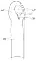
도 1은 본 발명의 일 실시예에 따른 오버튜브의 일측 외관을 나타내는 사시도이다.
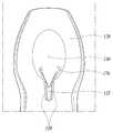
도 2는 오버튜브의 타측 외관을 나타내는 사시도이다.
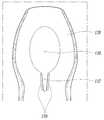
도 3은 오버튜브를 중심을 지나는 평면으로 절개하여 나타내는 사시도이다.
도 4는 오버튜브의 제1구멍 주위를 나타내는 일부 사시도이다.
도 5는 클립을 나타내는 사시도이다.
도 6은 클립이 가이드리브에 장착된 상태를 나타내는 일부 사시도이다.
도 7은 도 6에서 클립이 당겨져서 가이드리브 내측으로 이동된 상태를 나타내는 일부 사시도이다.
도 8은 가이드리브에서 연장형성된 연장가이드부에 클립이 장착된 상태를 나타내는 일부 사시도이다.1 is a perspective view illustrating an external appearance of one side of an overtube according to an embodiment of the present invention.
FIG. 2 is a perspective view illustrating an external appearance of the other side of the overtube.
3 is a perspective view showing the overtube by cutting it in a plane passing through the center.
Fig. 4 is a partial perspective view showing around the first hole of the overtube;
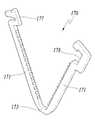
5 is a perspective view showing a clip.
6 is a partial perspective view showing a state in which the clip is mounted on the guide rib.
7 is a partial perspective view illustrating a state in which the clip is pulled and moved to the inside of the guide rib in FIG. 6 .
8 is a partial perspective view illustrating a state in which a clip is mounted on an extension guide portion extending from a guide rib.
본 발명은 다양한 변환을 가할 수 있고 여러 가지 실시예를 가질 수 있는 바, 특정 실시예를 예시하고 상세한 설명에 상세하게 설명하고자 한다. 그러나, 이는 본 발명을 특정한 실시 형태에 대해 한정하려는 것이 아니며, 본 발명의 사상 및 기술 범위에 포함되는 모든 변환, 균등물 내지 대체물을 포함하는 것으로 이해되어야 한다.Since the present invention can apply various transformations and can have various embodiments, specific embodiments are illustrated and described in detail in the detailed description. However, this is not intended to limit the present invention to specific embodiments, and it should be understood to include all modifications, equivalents and substitutes included in the spirit and scope of the present invention.
본 발명에서 사용한 용어는 단지 특정한 실시예를 설명하기 위해 사용된 것으로, 본 발명을 한정하려는 의도가 아니다. 단수의 표현은 문맥상 명백하게 다르게 뜻하지 않는 한, 복수의 표현을 포함한다. 본 발명에서, '포함하다' 또는 '가지다' 등의 용어는 명세서상에 기재된 특징, 숫자, 단계, 동작, 구성요소, 부품 또는 이들을 조합한 것이 존재함을 지정하려는 것이지, 하나 또는 그 이상의 다른 특징들이나 숫자, 단계, 동작, 구성요소, 부품 또는 이들을 조합한 것들의 존재 또는 부가 가능성을 미리 배제하지 않는 것으로 이해되어야 한다.The terms used in the present invention are only used to describe specific embodiments, and are not intended to limit the present invention. The singular expression includes the plural expression unless the context clearly dictates otherwise. In the present invention, terms such as 'comprising' or 'having' are intended to designate that the features, numbers, steps, operations, components, parts, or combinations thereof described in the specification exist, but one or more other features It should be understood that it does not preclude the possibility of the presence or addition of numbers, steps, operations, components, parts, or combinations thereof.
이하, 첨부된 도면을 참조하여 본 발명의 바람직한 실시예들을 상세히 설명한다. 이 때, 첨부된 도면에서 동일한 구성 요소는 가능한 동일한 부호로 나타내고 있음에 유의한다. 또한, 본 발명의 요지를 흐리게 할 수 있는 공지 기능 및 구성에 대한 상세한 설명은 생략할 것이다. 마찬가지 이유로 첨부 도면에 있어서 일부 구성요소는 과장되거나 생략되거나 개략적으로 도시되었다.Hereinafter, preferred embodiments of the present invention will be described in detail with reference to the accompanying drawings. At this time, it should be noted that in the accompanying drawings, the same components are denoted by the same reference numerals as much as possible. In addition, detailed descriptions of well-known functions and configurations that may obscure the gist of the present invention will be omitted. For the same reason, some components are exaggerated, omitted, or schematically illustrated in the accompanying drawings.
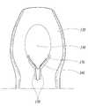
도 1은 본 발명의 일 실시예에 따른 오버튜브의 일측 외관을 나타내는 사시도이고, 도 2는 오버튜브의 타측 외관을 나타내는 사시도이며, 도 3은 오버튜브를 중심을 지나는 평면으로 절개하여 나타내는 사시도이다.1 is a perspective view showing the outer appearance of one side of the overtube according to an embodiment of the present invention, FIG. 2 is a perspective view showing the other side of the overtube, and FIG. 3 is a perspective view showing the overtube by cutting it in a plane passing through the center. .
본 발명의 오버튜브(100)는, 내시경 삽입시 내시경이 드나드는 길을 확보하기 위해 삽입되는 원형의 튜브본체부(110), 튜브본체부의 말단부 측면에 타원형으로 형성되어 내부로 병변을 도입하는 제1구멍(130), 및 제1구멍의 하부에 폭이 점점 좁아지도록 형성된 연장홈부(135)를 포함한다.The
오버튜브(100)는 식도 또는 직장를 통한 내시경 삽입시 내시경이 드나들 수 있는 길을 확보해주는 수단으로 사용되고 있다. 이하에서는 오버튜브(100)가 식도를 통해 삽입되는 경우를 예로 들어 설명한다.The
튜브본체부(110)는 입으로부터 식도, 십이지장을 거쳐 위 내부까지 삽입되는 원형의 튜브로서, 그 내부로 내시경이 통과할 수 있다.The
제1구멍(130)은 튜브본체부(110)의 말단부 측면에 관통 형성되는데, 튜브본체부(110)의 길이 방향으로 길게 타원형으로 형성될 수 있다. 오버튜브(100) 내부로 삽입되는 내시경 단부에 구비되는 집게 등의 장비를 제1구멍(130)을 통해 병변에 접근하여 병변을 잡아당길 수 있다. 이러한 내시경 장비로 병변을 끌어당겨 제1구멍(130)을 통해 오버튜브(100) 내부 공간으로 병변을 도입할 수 있다.The
제1구멍(130)의 하부에는 폭이 점점 좁아지도록 형성된 연장홈부(135)가 형성될 수 있다. 이 연장홈부(135)는 쐐기 형태의 관통공으로서 제1구멍(130)의 일부를 구성할 수 있다. 내부로 도입된 병변을 아래의 연장홈부(135) 쪽으로 더 당길수록 병변과 신체 조직의 연결부 단면적이 작아지기 때문에, 연결부를 다른 내시경 장비로 절제하기가 더욱 쉽게 만들 수 있다.An
도 1 또는 도 2에 도시된 바와 같이, 오버튜브(100)는 튜브본체부(110)의 말단부에 내경이 커졌다 작아지도록 형성된 말단확관부(120)를 더 포함할 수 있다. 말단확관부(120)의 내경 및 외경은 튜브본체부(110)의 내경 및 외경보다 점점 커졌다가 다시 작아지도록 형성될 수 있다. 말단확관부(120)의 외주면 윤곽은 유선형으로 형성될 수 있다. 말단확관부(120)의 단부 직경은 튜브본체부(110)의 단부 직경보다 약간 크게 형성될 수 있다. 이렇게 튜브본체부(110)의 말단부에 말단확관부(120)를 형성함으로써, 말단확관부(120)의 내부 공간을 확장시켜 더욱 큰 병변을 수용할 수 있다.As shown in FIG. 1 or FIG. 2 , the
제1구멍(130)은 말단확관부(120)의 측면에 형성될 수 있다. 또한, 연장홈부(135)도 말단확관부(120)의 측면에 형성되되, 연장홈부(135)의 하단이 말단확관부(120)와 튜브본체부(110)의 연결부에 배치되도록 형성될 수 있다.The
도 1(b) 및 도 2(b)에 도시된 바와 같이, 말단확관부(120)는 튜브본체부(110)에 1~15도 경사지게 연결될 수 있다. 다시 말해서, 말단확관부(120)의 가상의 중심선은 튜브본체부(110)의 중심선에 대해 1~15도 경사지게 교차되도록 배치될 수 있다. 식도와 연결되는 위의 입구 내벽은 식도에 대해 소정 각도 경사지게 배치되어 있으므로, 말단확관부(120)는 튜브본체부(110)에 대해 경사지게 연결되는 것이 좋다. 튜브본체부(110)에 대한 말단확관부(120)의 경사 각도가 너무 크면 오버튜브(100)를 위 내부로 삽입하는 것이 어려울 수 있으므로, 경사 각도는 15도 이내인 것이 바람직하다.As shown in Figures 1 (b) and 2 (b), the end-expanded
제1구멍(130)은 말단확관부(120)의 측면 중에서 튜브본체부(110)의 측면 윤곽과 연결되는 각도가 최대가 되는 부위에 형성될 수 있다. 이에 따라, 말단확관부(120)의 제1구멍(130)은 병변이 있는 조직 내면에 밀착될 수 있고, 제1구멍(130)을 통과하는 내시경 단부의 장비가 꺽이는 각도를 덜 꺽이도록 줄일 수 있다. 그래서, 제1구멍(130)을 통해 내시경 장비로 병변 부위를 쉽게 집어서 말단확관부(120) 내측으로 끌어들일 수 있다.The
도 2에 도시된 바와 같이, 말단확관부(120)는 제1구멍(130)의 반대쪽 측면에 형성된 제2구멍(140)을 더 포함할 수 있다. 제2구멍(140)도 제1구멍(130)과 같거나 작은 크기로 타원형으로 관통형성될 수 있다. 제2구멍(140)은 말단확관부(120)의 측면에서 튜브본체부(110)의 측면 윤곽과 연결되는 각도가 최소가 되는 부위에 형성될 수 있다. 제2구멍(140)의 하단은 말단확관부(120)와 튜브본체부(110)의 연결부보다 약간 아래에 배치될 수 있다. 말단확관부(120)에 제2구멍(140)을 더 형성함으로써 말단확관부(120) 내부 공간에 수용되는 병변 조직의 부피를 더욱 증가시킬 수 있다.As shown in FIG. 2 , the
도 4는 오버튜브의 제1구멍 주위를 나타내는 일부 사시도이고, 도 5는 클립을 나타내는 사시도이며, 도 6은 클립이 가이드리브에 장착된 상태를 나타내는 일부 사시도이고, 도 7은 도 6에서 클립이 당겨져서 가이드리브 내측으로 이동된 상태를 나타내는 일부 사시도이다.4 is a partial perspective view showing the circumference of the first hole of the overtube, FIG. 5 is a perspective view showing a clip, FIG. 6 is a partial perspective view showing a state in which the clip is mounted to the guide rib, and FIG. 7 is the clip in FIG. It is a partial perspective view showing a state that is pulled and moved to the inside of the guide rib.
도 2(a), 도 3 및 도 4에 도시된 바와 같이, 말단확관부(120)의 내주면에는 연장홈부(135)의 좌우에 한 쌍의 가이드리브(150)가 돌출형성될 수 있다. 한 쌍의 가이드리브(150)는 서로 소정의 예각을 이루도록 연장홈부(135)의 좌우에 이격되도록 배치될 수 있다. 한 쌍의 가이드리브(150)는 그 폭방향 단면이 "ㄱ"자 모양으로 형성되고, 서로 마주보도록 배치될 수 있다.2(a), 3 and 4, a pair of
도 5 내지 도 7에 도시된 바와 같이, 한 쌍의 가이드리브(150) 사이에는 클립(170)이 장착될 수 있다. 클립(170)은 한 쌍의 가이드리브(150)에 의해 안내되고 뒤로 당김에 따라 오므림으로써 제1구멍(130)을 통해 말단확관부(120) 내부로 끌어들인 병변을 고정할 수 있다.5 to 7 , a
클립(170)은 한 쌍의 몸체부(171)가 탄성연결부(173)에 의해 클립이 벌어지는 방향으로 복원력을 작용하도록 연결될 수 있다. 한 쌍의 몸체부(171)가 오므려졌을 때 마주보는 몸체부(171)의 각 내측면에는 톱니부(175)가 형성되어, 도입된 병변 주위를 확실히 고정할 수 있다. 일측 몸체부(171)의 단부에는 내측방향으로 돌기부(177)가 형성되고, 타측 몸체부(171)의 단부에는 내측방향으로 홈부(178)가 형성될 수 있다. 그래서, 클립(170)을 오므렸을 때 돌기부(177)가 홈부(178)에 삽입되어 클립(170)이 병변 주위를 고정한 상태를 유지할 수 있다.The
도 6에서와 같이, 클립(170)은 한 쌍의 가이드리브(150) 상단에 장착되고 제1구멍(130)의 하부 테두리 주위에 배치될 수 있다. 이 상태에서 내시경 장비로 병변을 제1구멍(130) 통해 말단확관부(120) 내부로 끌어들인 다음, 클립(170)의 탄성연결부(173)에 연결된 줄(미도시)을 잡아당기면, 도 7에서와 같이 한 쌍의 가이드리브(150)에 의해 클립(170)이 오므려질 수 있다. 클립(170)을 더욱 아래로 당기면 클립(170)의 톱니부(175)들이 병변 주위를 꽉 물어서 고정할 수 있다. 그러면, 다른 내시경 장비로 클립(170)에 고정된 부위 바로 안쪽을 절제한 다음, 절제된 병변 조각을 흡입하여 제거할 수 있다.As shown in FIG. 6 , the
도 8은 가이드리브에서 연장형성된 연장가이드부에 클립이 장착된 상태를 나타내는 일부 사시도이다. 즉, 도 8은 가이드리브에 연장가이드부가 일체로 형성된 실시예를 나타낸다.8 is a partial perspective view illustrating a state in which a clip is mounted on an extension guide portion extending from a guide rib. That is, FIG. 8 shows an embodiment in which the extension guide part is integrally formed with the guide rib.
본 실시예에서 한 쌍의 가이드리브(150)에는 한 쌍의 연장가이드부(160)가 제1구멍(130)의 하부 테두리 양측으로 연장되어 일체로 형성될 수 있다. 한 쌍의 연장가이드부(160)도 그 단면이 "ㄱ"자 형태로 형성되고 서로 마주보도록 배치될 수 있다. 클립(170)은 초기에 제1구멍(130)의 하부 테두리 양측에 배치되는데, 한 쌍의 연장가이드부(160)가 클립(170)을 안정적으로 지지할 수 있다. 클립(170)의 탄성연결부(173)는 클립(170)이 벌어지는 방향으로 복원력을 작용하므로, 클립(170)이 한 쌍의 연장가이드부(160) 내측에 밀착되어 지지될 수 있다.In this embodiment, the pair of
도 6의 실시예에서 한 쌍의 가이드리브(150)는 직선 형태로 형성되어 있는 반면에, 도 8의 실시예에서 한 쌍의 가이드리브(150)와 한 쌍의 연장가이드부(160)의 각 연결부는 곡선 형태로 형성될 수 있다. 이에 따라, 클립(170)을 잡아당겨서 오므릴 때, 클립(170)이 한 쌍의 연장가이드부(160)와 한 쌍의 가이드리브(150)로 부드럽게 슬라이딩하면서 오므려질 수 있다.In the embodiment of FIG. 6 , the pair of
본 발명의 오버튜브에 의하면, 말단부에 확관부를 형성하고 확관부 측면에 종양 등의 병변을 도입하기 위한 구멍을 형성하여 내시경을 통해 큰 종양을 쉽게 제거할 수 있다.According to the overtube of the present invention, a large tumor can be easily removed through an endoscope by forming an expansion tube at the distal end and forming a hole for introducing a lesion such as a tumor on the side of the expansion tube.
이상, 본 발명의 일 실시예에 대하여 설명하였으나, 해당 기술 분야에서 통상의 지식을 가진 자라면 청구범위에 기재된 본 발명의 사상으로부터 벗어나지 않는 범위 내에서, 구성 요소의 부가, 변경, 삭제 또는 추가 등에 의해 본 발명을 다양하게 수정 및 변경할 수 있을 것이며, 이 또한 본 발명의 권리범위 내에 포함된다고 할 것이다.In the above, an embodiment of the present invention has been described, but those of ordinary skill in the art can add, change, delete or add components within the scope that does not depart from the spirit of the present invention described in the claims. Various modifications and changes of the present invention will be possible by this, and this will also be included within the scope of the present invention.
100: 오버튜브
110: 튜브본체부
120: 말단확관부
130: 제1구멍
135: 연장홈부
140: 제2구멍
150: 가이드리브
160: 연장가이드부
170: 클립
171: 몸체부
173: 탄성연결부
175: 톱니부
177: 돌기부
178: 홈부100: over tube
110: tube body part
120: end expansion tube
130: first hole
135: extended groove
140: second hole
150: guide rib
160: extension guide part
170: clip
171: body part
173: elastic connection part
175: toothed part
177: protrusion
178: home
Claims (5)
Translated fromKorean상기 튜브본체부의 말단부에 내경이 커졌다 작아지도록 형성된 말단확관부;
상기 말단확관부의 측면에 타원형으로 형성되어 내부로 병변을 도입하는 제1구멍;
상기 제1구멍의 하부에 폭이 점점 좁아지도록 형성된 연장홈부;
상기 말단확관부의 내주면에 상기 연장홈부의 좌우에 돌출형성된 한 쌍의 가이드리브; 및
상기 한 쌍의 가이드리브 사이에 장착되어 뒤로 당김에 따라 오므림으로써 상기 제1구멍을 통해 상기 말단확관부 내부로 끌어들인 병변을 고정하는 클립을 포함하는 오버튜브.a circular tube body that is inserted to secure a path for the endoscope to enter and exit when the endoscope is inserted;
an end-expanding part formed so that the inner diameter increases and decreases at the distal end of the tube body;
a first hole formed in an elliptical shape on the side of the distal cannula to introduce a lesion into the inside;
an extension groove formed at a lower portion of the first hole to become narrower in width;
a pair of guide ribs protruding from the left and right sides of the extended groove on the inner circumferential surface of the end-expanding part; and
and a clip mounted between the pair of guide ribs to fix the lesion drawn into the distal cannula through the first hole by being pulled back by pulling it back.
상기 말단확관부는 상기 튜브본체부에 1~15도 경사지게 연결된 것을 특징으로 하는 오버튜브.According to claim 1,
The end-expanding part is an overtube, characterized in that it is connected to the tube body part at an angle of 1 to 15 degrees.
상기 말단확관부는 상기 제1구멍의 반대쪽 측면에 형성된 제2구멍을 더 포함하는 것을 특징으로 하는 오버튜브.According to claim 1,
The end expansion tube portion overtube, characterized in that it further comprises a second hole formed on a side opposite to the first hole.
Priority Applications (2)
| Application Number | Priority Date | Filing Date | Title |
|---|---|---|---|
| KR1020210021158AKR102296937B1 (en) | 2021-02-17 | 2021-02-17 | Overtube |
| PCT/KR2021/015443WO2022177098A1 (en) | 2021-02-17 | 2021-10-29 | Overtube |
Applications Claiming Priority (1)
| Application Number | Priority Date | Filing Date | Title |
|---|---|---|---|
| KR1020210021158AKR102296937B1 (en) | 2021-02-17 | 2021-02-17 | Overtube |
Publications (1)
| Publication Number | Publication Date |
|---|---|
| KR102296937B1true KR102296937B1 (en) | 2021-09-02 |
Family
ID=77794426
Family Applications (1)
| Application Number | Title | Priority Date | Filing Date |
|---|---|---|---|
| KR1020210021158AActiveKR102296937B1 (en) | 2021-02-17 | 2021-02-17 | Overtube |
Country Status (2)
| Country | Link |
|---|---|
| KR (1) | KR102296937B1 (en) |
| WO (1) | WO2022177098A1 (en) |
Citations (7)
| Publication number | Priority date | Publication date | Assignee | Title |
|---|---|---|---|---|
| JP2005103140A (en)* | 2003-10-01 | 2005-04-21 | Olympus Corp | Insertion aid for treatment of large intestine whole layer resection, and medical instrument system thereof |
| JP2005296644A (en)* | 2004-04-07 | 2005-10-27 | Olympus Corp | Medical ligature suturing apparatus and medical ligature suturing system |
| KR100548873B1 (en) | 2003-05-30 | 2006-02-02 | (주) 태웅메디칼 | Medical band ligation machine |
| WO2015069952A1 (en)* | 2013-11-11 | 2015-05-14 | Cross Bay Medical, Inc. | Method and apparatus of tubal patency catheter and delivery systems |
| KR101563175B1 (en) | 2014-02-24 | 2015-11-06 | (주) 태웅메디칼 | Overtube for endoscope |
| KR101696696B1 (en) | 2014-02-27 | 2017-01-23 | 샤인인 바이오테크놀로지 코., 엘티디. | overtube AND USES THEREOF |
| KR102045383B1 (en) | 2017-07-28 | 2019-11-15 | (재)예수병원유지재단 | Overtube |
Family Cites Families (3)
| Publication number | Priority date | Publication date | Assignee | Title |
|---|---|---|---|---|
| JPH10137248A (en)* | 1996-11-13 | 1998-05-26 | Olympus Optical Co Ltd | Suction biopsy tool |
| JP3845173B2 (en)* | 1997-04-15 | 2006-11-15 | ペンタックス株式会社 | Endoscope for ligation treatment |
| JP3722729B2 (en)* | 2001-06-04 | 2005-11-30 | オリンパス株式会社 | Endoscope treatment device |
- 2021
- 2021-02-17KRKR1020210021158Apatent/KR102296937B1/enactiveActive
- 2021-10-29WOPCT/KR2021/015443patent/WO2022177098A1/ennot_activeCeased
Patent Citations (7)
| Publication number | Priority date | Publication date | Assignee | Title |
|---|---|---|---|---|
| KR100548873B1 (en) | 2003-05-30 | 2006-02-02 | (주) 태웅메디칼 | Medical band ligation machine |
| JP2005103140A (en)* | 2003-10-01 | 2005-04-21 | Olympus Corp | Insertion aid for treatment of large intestine whole layer resection, and medical instrument system thereof |
| JP2005296644A (en)* | 2004-04-07 | 2005-10-27 | Olympus Corp | Medical ligature suturing apparatus and medical ligature suturing system |
| WO2015069952A1 (en)* | 2013-11-11 | 2015-05-14 | Cross Bay Medical, Inc. | Method and apparatus of tubal patency catheter and delivery systems |
| KR101563175B1 (en) | 2014-02-24 | 2015-11-06 | (주) 태웅메디칼 | Overtube for endoscope |
| KR101696696B1 (en) | 2014-02-27 | 2017-01-23 | 샤인인 바이오테크놀로지 코., 엘티디. | overtube AND USES THEREOF |
| KR102045383B1 (en) | 2017-07-28 | 2019-11-15 | (재)예수병원유지재단 | Overtube |
Also Published As
| Publication number | Publication date |
|---|---|
| WO2022177098A1 (en) | 2022-08-25 |
Similar Documents
| Publication | Publication Date | Title |
|---|---|---|
| JP4875445B2 (en) | Endoscopic treatment tool | |
| US20240307068A1 (en) | Hemostasis clip | |
| JP7048861B2 (en) | Intraluminal minimally invasive treatment system | |
| ES2381753T3 (en) | Surgical port and breakable introducer assembly | |
| US6352503B1 (en) | Endoscopic surgery apparatus | |
| US8206401B2 (en) | Endoscope cutting and retrieving snare instrument | |
| CN100500103C (en) | Surgical treatment instrument | |
| JP4242491B2 (en) | Endoscopic treatment device | |
| JP5133245B2 (en) | Rectal insertable surgical system | |
| JP5867746B2 (en) | 3D retractor | |
| US20070066869A1 (en) | Endoscopic assembly including cap and sheath | |
| US20090048487A1 (en) | Treatment device | |
| JP2000033071A (en) | Endoscope therapeutic device | |
| US9782197B2 (en) | Tissue grasping device | |
| CN111163702A (en) | Devices and methods for tissue retraction | |
| JPH09201330A (en) | Drainage tube assembly | |
| US12150643B2 (en) | Endoscopic treatment device | |
| CA2682293C (en) | Endoscopic suction device for mucosectomy | |
| KR102296937B1 (en) | Overtube | |
| JP3129543U (en) | Overtube | |
| JP7714114B2 (en) | Over-the-scope clip with compliant mechanism | |
| JP2015506185A (en) | Laparoscopy seal bridge | |
| KR102045383B1 (en) | Overtube | |
| JP5912473B2 (en) | Micro Snake Retractor | |
| JP3411782B2 (en) | Endoscope for ligating |
Legal Events
| Date | Code | Title | Description |
|---|---|---|---|
| PA0109 | Patent application | St.27 status event code:A-0-1-A10-A12-nap-PA0109 | |
| PA0201 | Request for examination | St.27 status event code:A-1-2-D10-D11-exm-PA0201 | |
| PA0302 | Request for accelerated examination | St.27 status event code:A-1-2-D10-D17-exm-PA0302 St.27 status event code:A-1-2-D10-D16-exm-PA0302 | |
| PE0902 | Notice of grounds for rejection | St.27 status event code:A-1-2-D10-D21-exm-PE0902 | |
| E13-X000 | Pre-grant limitation requested | St.27 status event code:A-2-3-E10-E13-lim-X000 | |
| P11-X000 | Amendment of application requested | St.27 status event code:A-2-2-P10-P11-nap-X000 | |
| P13-X000 | Application amended | St.27 status event code:A-2-2-P10-P13-nap-X000 | |
| PE0701 | Decision of registration | St.27 status event code:A-1-2-D10-D22-exm-PE0701 | |
| GRNT | Written decision to grant | ||
| PR0701 | Registration of establishment | St.27 status event code:A-2-4-F10-F11-exm-PR0701 | |
| PR1002 | Payment of registration fee | St.27 status event code:A-2-2-U10-U11-oth-PR1002 Fee payment year number:1 | |
| PG1601 | Publication of registration | St.27 status event code:A-4-4-Q10-Q13-nap-PG1601 | |
| R18-X000 | Changes to party contact information recorded | St.27 status event code:A-5-5-R10-R18-oth-X000 | |
| PR1001 | Payment of annual fee | St.27 status event code:A-4-4-U10-U11-oth-PR1001 Fee payment year number:4 | |
| PR1001 | Payment of annual fee | St.27 status event code:A-4-4-U10-U11-oth-PR1001 Fee payment year number:5 |