KR102296026B1 - Electrode device - Google Patents
Electrode deviceDownload PDFInfo
- Publication number
- KR102296026B1 KR102296026B1KR1020200167806AKR20200167806AKR102296026B1KR 102296026 B1KR102296026 B1KR 102296026B1KR 1020200167806 AKR1020200167806 AKR 1020200167806AKR 20200167806 AKR20200167806 AKR 20200167806AKR 102296026 B1KR102296026 B1KR 102296026B1
- Authority
- KR
- South Korea
- Prior art keywords
- electrode
- clamping piece
- electrode unit
- base layer
- layer
- Prior art date
- Legal status (The legal status is an assumption and is not a legal conclusion. Google has not performed a legal analysis and makes no representation as to the accuracy of the status listed.)
- Active
Links
- 230000008878couplingEffects0.000claimsabstractdescription42
- 238000010168coupling processMethods0.000claimsabstractdescription42
- 238000005859coupling reactionMethods0.000claimsabstractdescription42
- 210000005036nerveAnatomy0.000claimsabstractdescription25
- 238000004804windingMethods0.000claimsabstractdescription25
- 230000000903blocking effectEffects0.000claimsabstractdescription4
- 238000000034methodMethods0.000claimsdescription18
- 230000003014reinforcing effectEffects0.000claimsdescription2
- 238000003780insertionMethods0.000claims1
- 230000037431insertionEffects0.000claims1
- 230000005540biological transmissionEffects0.000description3
- 239000002184metalSubstances0.000description3
- 229910052751metalInorganic materials0.000description3
- 230000002787reinforcementEffects0.000description3
- 210000002254renal arteryAnatomy0.000description3
- 230000008569processEffects0.000description2
- 229910001006ConstantanInorganic materials0.000description1
- RYGMFSIKBFXOCR-UHFFFAOYSA-NCopperChemical compound[Cu]RYGMFSIKBFXOCR-UHFFFAOYSA-N0.000description1
- 206010020772HypertensionDiseases0.000description1
- 208000019693Lung diseaseDiseases0.000description1
- 101001045744Sus scrofa Hepatocyte nuclear factor 1-betaProteins0.000description1
- 238000002679ablationMethods0.000description1
- 210000003403autonomic nervous systemAnatomy0.000description1
- 230000008901benefitEffects0.000description1
- 210000004204blood vesselAnatomy0.000description1
- 229910052802copperInorganic materials0.000description1
- 239000010949copperSubstances0.000description1
- 230000000694effectsEffects0.000description1
- 230000005611electricityEffects0.000description1
- PCHJSUWPFVWCPO-UHFFFAOYSA-NgoldChemical compound[Au]PCHJSUWPFVWCPO-UHFFFAOYSA-N0.000description1
- 229910052737goldInorganic materials0.000description1
- 239000010931goldSubstances0.000description1
- 208000019622heart diseaseDiseases0.000description1
- 210000003734kidneyAnatomy0.000description1
- 210000004072lungAnatomy0.000description1
- 239000000463materialSubstances0.000description1
- 238000012986modificationMethods0.000description1
- 230000004048modificationEffects0.000description1
- 210000005037parasympathetic nerveAnatomy0.000description1
- 230000002685pulmonary effectEffects0.000description1
- 229910001220stainless steelInorganic materials0.000description1
- 239000010935stainless steelSubstances0.000description1
- 230000000638stimulationEffects0.000description1
- 230000002889sympathetic effectEffects0.000description1
- 238000002604ultrasonographyMethods0.000description1
Images


Classifications
- A—HUMAN NECESSITIES
- A61—MEDICAL OR VETERINARY SCIENCE; HYGIENE
- A61B—DIAGNOSIS; SURGERY; IDENTIFICATION
- A61B18/00—Surgical instruments, devices or methods for transferring non-mechanical forms of energy to or from the body
- A61B18/04—Surgical instruments, devices or methods for transferring non-mechanical forms of energy to or from the body by heating
- A61B18/12—Surgical instruments, devices or methods for transferring non-mechanical forms of energy to or from the body by heating by passing a current through the tissue to be heated, e.g. high-frequency current
- A61B18/14—Probes or electrodes therefor
- A61B18/149—Probes or electrodes therefor bow shaped or with rotatable body at cantilever end, e.g. for resectoscopes, or coagulating rollers
- A—HUMAN NECESSITIES
- A61—MEDICAL OR VETERINARY SCIENCE; HYGIENE
- A61B—DIAGNOSIS; SURGERY; IDENTIFICATION
- A61B18/00—Surgical instruments, devices or methods for transferring non-mechanical forms of energy to or from the body
- A61B18/04—Surgical instruments, devices or methods for transferring non-mechanical forms of energy to or from the body by heating
- A61B18/12—Surgical instruments, devices or methods for transferring non-mechanical forms of energy to or from the body by heating by passing a current through the tissue to be heated, e.g. high-frequency current
- A61B18/14—Probes or electrodes therefor
- A—HUMAN NECESSITIES
- A61—MEDICAL OR VETERINARY SCIENCE; HYGIENE
- A61N—ELECTROTHERAPY; MAGNETOTHERAPY; RADIATION THERAPY; ULTRASOUND THERAPY
- A61N1/00—Electrotherapy; Circuits therefor
- A61N1/02—Details
- A61N1/04—Electrodes
- A61N1/05—Electrodes for implantation or insertion into the body, e.g. heart electrode
- A61N1/0551—Spinal or peripheral nerve electrodes
- A61N1/0556—Cuff electrodes
- A—HUMAN NECESSITIES
- A61—MEDICAL OR VETERINARY SCIENCE; HYGIENE
- A61B—DIAGNOSIS; SURGERY; IDENTIFICATION
- A61B18/00—Surgical instruments, devices or methods for transferring non-mechanical forms of energy to or from the body
- A61B18/04—Surgical instruments, devices or methods for transferring non-mechanical forms of energy to or from the body by heating
- A61B18/12—Surgical instruments, devices or methods for transferring non-mechanical forms of energy to or from the body by heating by passing a current through the tissue to be heated, e.g. high-frequency current
- A61B18/14—Probes or electrodes therefor
- A61B18/1402—Probes for open surgery
- A—HUMAN NECESSITIES
- A61—MEDICAL OR VETERINARY SCIENCE; HYGIENE
- A61B—DIAGNOSIS; SURGERY; IDENTIFICATION
- A61B18/00—Surgical instruments, devices or methods for transferring non-mechanical forms of energy to or from the body
- A61B18/04—Surgical instruments, devices or methods for transferring non-mechanical forms of energy to or from the body by heating
- A61B18/12—Surgical instruments, devices or methods for transferring non-mechanical forms of energy to or from the body by heating by passing a current through the tissue to be heated, e.g. high-frequency current
- A61B18/14—Probes or electrodes therefor
- A61B18/1482—Probes or electrodes therefor having a long rigid shaft for accessing the inner body transcutaneously in minimal invasive surgery, e.g. laparoscopy
- A—HUMAN NECESSITIES
- A61—MEDICAL OR VETERINARY SCIENCE; HYGIENE
- A61B—DIAGNOSIS; SURGERY; IDENTIFICATION
- A61B18/00—Surgical instruments, devices or methods for transferring non-mechanical forms of energy to or from the body
- A61B18/04—Surgical instruments, devices or methods for transferring non-mechanical forms of energy to or from the body by heating
- A61B18/12—Surgical instruments, devices or methods for transferring non-mechanical forms of energy to or from the body by heating by passing a current through the tissue to be heated, e.g. high-frequency current
- A61B18/14—Probes or electrodes therefor
- A61B18/1492—Probes or electrodes therefor having a flexible, catheter-like structure, e.g. for heart ablation
- A—HUMAN NECESSITIES
- A61—MEDICAL OR VETERINARY SCIENCE; HYGIENE
- A61N—ELECTROTHERAPY; MAGNETOTHERAPY; RADIATION THERAPY; ULTRASOUND THERAPY
- A61N1/00—Electrotherapy; Circuits therefor
- A61N1/02—Details
- A61N1/04—Electrodes
- A61N1/05—Electrodes for implantation or insertion into the body, e.g. heart electrode
- A61N1/0551—Spinal or peripheral nerve electrodes
- A61N1/0558—Anchoring or fixation means therefor
- A—HUMAN NECESSITIES
- A61—MEDICAL OR VETERINARY SCIENCE; HYGIENE
- A61N—ELECTROTHERAPY; MAGNETOTHERAPY; RADIATION THERAPY; ULTRASOUND THERAPY
- A61N1/00—Electrotherapy; Circuits therefor
- A61N1/18—Applying electric currents by contact electrodes
- A61N1/32—Applying electric currents by contact electrodes alternating or intermittent currents
- A61N1/36—Applying electric currents by contact electrodes alternating or intermittent currents for stimulation
- A61N1/3605—Implantable neurostimulators for stimulating central or peripheral nerve system
- A61N1/3606—Implantable neurostimulators for stimulating central or peripheral nerve system adapted for a particular treatment
- A61N1/36114—Cardiac control, e.g. by vagal stimulation
- A—HUMAN NECESSITIES
- A61—MEDICAL OR VETERINARY SCIENCE; HYGIENE
- A61N—ELECTROTHERAPY; MAGNETOTHERAPY; RADIATION THERAPY; ULTRASOUND THERAPY
- A61N1/00—Electrotherapy; Circuits therefor
- A61N1/18—Applying electric currents by contact electrodes
- A61N1/32—Applying electric currents by contact electrodes alternating or intermittent currents
- A61N1/36—Applying electric currents by contact electrodes alternating or intermittent currents for stimulation
- A61N1/3605—Implantable neurostimulators for stimulating central or peripheral nerve system
- A61N1/36128—Control systems
- A61N1/36135—Control systems using physiological parameters
- A—HUMAN NECESSITIES
- A61—MEDICAL OR VETERINARY SCIENCE; HYGIENE
- A61B—DIAGNOSIS; SURGERY; IDENTIFICATION
- A61B17/00—Surgical instruments, devices or methods
- A61B17/00234—Surgical instruments, devices or methods for minimally invasive surgery
- A61B2017/00238—Type of minimally invasive operation
- A61B2017/00243—Type of minimally invasive operation cardiac
- A61B2017/00256—Creating an electrical block
- A—HUMAN NECESSITIES
- A61—MEDICAL OR VETERINARY SCIENCE; HYGIENE
- A61B—DIAGNOSIS; SURGERY; IDENTIFICATION
- A61B18/00—Surgical instruments, devices or methods for transferring non-mechanical forms of energy to or from the body
- A61B2018/00053—Mechanical features of the instrument of device
- A61B2018/00184—Moving parts
- A61B2018/00196—Moving parts reciprocating lengthwise
- A—HUMAN NECESSITIES
- A61—MEDICAL OR VETERINARY SCIENCE; HYGIENE
- A61B—DIAGNOSIS; SURGERY; IDENTIFICATION
- A61B18/00—Surgical instruments, devices or methods for transferring non-mechanical forms of energy to or from the body
- A61B2018/00315—Surgical instruments, devices or methods for transferring non-mechanical forms of energy to or from the body for treatment of particular body parts
- A61B2018/00345—Vascular system
- A61B2018/00404—Blood vessels other than those in or around the heart
- A—HUMAN NECESSITIES
- A61—MEDICAL OR VETERINARY SCIENCE; HYGIENE
- A61B—DIAGNOSIS; SURGERY; IDENTIFICATION
- A61B18/00—Surgical instruments, devices or methods for transferring non-mechanical forms of energy to or from the body
- A61B2018/00315—Surgical instruments, devices or methods for transferring non-mechanical forms of energy to or from the body for treatment of particular body parts
- A61B2018/00434—Neural system
- A—HUMAN NECESSITIES
- A61—MEDICAL OR VETERINARY SCIENCE; HYGIENE
- A61B—DIAGNOSIS; SURGERY; IDENTIFICATION
- A61B18/00—Surgical instruments, devices or methods for transferring non-mechanical forms of energy to or from the body
- A61B2018/00315—Surgical instruments, devices or methods for transferring non-mechanical forms of energy to or from the body for treatment of particular body parts
- A61B2018/00505—Urinary tract
- A61B2018/00511—Kidney
- A—HUMAN NECESSITIES
- A61—MEDICAL OR VETERINARY SCIENCE; HYGIENE
- A61B—DIAGNOSIS; SURGERY; IDENTIFICATION
- A61B18/00—Surgical instruments, devices or methods for transferring non-mechanical forms of energy to or from the body
- A61B2018/00315—Surgical instruments, devices or methods for transferring non-mechanical forms of energy to or from the body for treatment of particular body parts
- A61B2018/00541—Lung or bronchi
- A—HUMAN NECESSITIES
- A61—MEDICAL OR VETERINARY SCIENCE; HYGIENE
- A61B—DIAGNOSIS; SURGERY; IDENTIFICATION
- A61B18/00—Surgical instruments, devices or methods for transferring non-mechanical forms of energy to or from the body
- A61B2018/00571—Surgical instruments, devices or methods for transferring non-mechanical forms of energy to or from the body for achieving a particular surgical effect
- A61B2018/00577—Ablation
- A—HUMAN NECESSITIES
- A61—MEDICAL OR VETERINARY SCIENCE; HYGIENE
- A61B—DIAGNOSIS; SURGERY; IDENTIFICATION
- A61B18/00—Surgical instruments, devices or methods for transferring non-mechanical forms of energy to or from the body
- A61B2018/00571—Surgical instruments, devices or methods for transferring non-mechanical forms of energy to or from the body for achieving a particular surgical effect
- A61B2018/00601—Cutting
- A—HUMAN NECESSITIES
- A61—MEDICAL OR VETERINARY SCIENCE; HYGIENE
- A61B—DIAGNOSIS; SURGERY; IDENTIFICATION
- A61B18/00—Surgical instruments, devices or methods for transferring non-mechanical forms of energy to or from the body
- A61B2018/00636—Sensing and controlling the application of energy
- A61B2018/00773—Sensed parameters
- A61B2018/00791—Temperature
- A61B2018/00821—Temperature measured by a thermocouple
- A—HUMAN NECESSITIES
- A61—MEDICAL OR VETERINARY SCIENCE; HYGIENE
- A61B—DIAGNOSIS; SURGERY; IDENTIFICATION
- A61B18/00—Surgical instruments, devices or methods for transferring non-mechanical forms of energy to or from the body
- A61B2018/00636—Sensing and controlling the application of energy
- A61B2018/00773—Sensed parameters
- A61B2018/00839—Bioelectrical parameters, e.g. ECG, EEG
- A—HUMAN NECESSITIES
- A61—MEDICAL OR VETERINARY SCIENCE; HYGIENE
- A61B—DIAGNOSIS; SURGERY; IDENTIFICATION
- A61B18/00—Surgical instruments, devices or methods for transferring non-mechanical forms of energy to or from the body
- A61B18/04—Surgical instruments, devices or methods for transferring non-mechanical forms of energy to or from the body by heating
- A61B18/12—Surgical instruments, devices or methods for transferring non-mechanical forms of energy to or from the body by heating by passing a current through the tissue to be heated, e.g. high-frequency current
- A61B18/14—Probes or electrodes therefor
- A61B2018/1405—Electrodes having a specific shape
- A61B2018/142—Electrodes having a specific shape at least partly surrounding the target, e.g. concave, curved or in the form of a cave
- A—HUMAN NECESSITIES
- A61—MEDICAL OR VETERINARY SCIENCE; HYGIENE
- A61B—DIAGNOSIS; SURGERY; IDENTIFICATION
- A61B18/00—Surgical instruments, devices or methods for transferring non-mechanical forms of energy to or from the body
- A61B18/04—Surgical instruments, devices or methods for transferring non-mechanical forms of energy to or from the body by heating
- A61B18/12—Surgical instruments, devices or methods for transferring non-mechanical forms of energy to or from the body by heating by passing a current through the tissue to be heated, e.g. high-frequency current
- A61B18/14—Probes or electrodes therefor
- A61B2018/1405—Electrodes having a specific shape
- A61B2018/1435—Spiral
- A—HUMAN NECESSITIES
- A61—MEDICAL OR VETERINARY SCIENCE; HYGIENE
- A61B—DIAGNOSIS; SURGERY; IDENTIFICATION
- A61B18/00—Surgical instruments, devices or methods for transferring non-mechanical forms of energy to or from the body
- A61B18/04—Surgical instruments, devices or methods for transferring non-mechanical forms of energy to or from the body by heating
- A61B18/12—Surgical instruments, devices or methods for transferring non-mechanical forms of energy to or from the body by heating by passing a current through the tissue to be heated, e.g. high-frequency current
- A61B18/14—Probes or electrodes therefor
- A61B2018/1465—Deformable electrodes
- A—HUMAN NECESSITIES
- A61—MEDICAL OR VETERINARY SCIENCE; HYGIENE
- A61B—DIAGNOSIS; SURGERY; IDENTIFICATION
- A61B18/00—Surgical instruments, devices or methods for transferring non-mechanical forms of energy to or from the body
- A61B18/04—Surgical instruments, devices or methods for transferring non-mechanical forms of energy to or from the body by heating
- A61B18/12—Surgical instruments, devices or methods for transferring non-mechanical forms of energy to or from the body by heating by passing a current through the tissue to be heated, e.g. high-frequency current
- A61B18/14—Probes or electrodes therefor
- A61B2018/1475—Electrodes retractable in or deployable from a housing
Landscapes
- Health & Medical Sciences (AREA)
- Life Sciences & Earth Sciences (AREA)
- Engineering & Computer Science (AREA)
- Surgery (AREA)
- Public Health (AREA)
- Biomedical Technology (AREA)
- Nuclear Medicine, Radiotherapy & Molecular Imaging (AREA)
- Animal Behavior & Ethology (AREA)
- General Health & Medical Sciences (AREA)
- Veterinary Medicine (AREA)
- Heart & Thoracic Surgery (AREA)
- Molecular Biology (AREA)
- Medical Informatics (AREA)
- Otolaryngology (AREA)
- Plasma & Fusion (AREA)
- Physics & Mathematics (AREA)
- Cardiology (AREA)
- Neurosurgery (AREA)
- Radiology & Medical Imaging (AREA)
- Neurology (AREA)
- Orthopedic Medicine & Surgery (AREA)
- Physiology (AREA)
- Biophysics (AREA)
- Electrotherapy Devices (AREA)
- Surgical Instruments (AREA)
- Electrical Discharge Machining, Electrochemical Machining, And Combined Machining (AREA)
- Polarising Elements (AREA)
Abstract
Translated fromKoreanDescription
Translated fromKorean본 발명은 체내의 신경을 차단 또는 조절하기 위한 전극 장치이다.The present invention is an electrode device for blocking or controlling nerves in the body.
신경차단술은 비정상적으로 과도하게 활성화된 자율신경계를 제어하기 위해 특정 신경을 손상시키는 시술을 말한다. 예를 들어, 신장신경차단술은 신장으로 향하는 신장교감신경을 손상시켜 고혈압과 심장질환을 치료할 수 있고, 폐신경차단술은 폐로 향하는 부교감신경을 손상시켜 폐질환을 치료할 수 있다.Nerve block refers to a procedure that damages a specific nerve to control the abnormally overactive autonomic nervous system. For example, renal nerve block can treat high blood pressure and heart disease by damaging the renal sympathetic nerve going to the kidneys, and pulmonary nerve block can treat lung disease by damaging the parasympathetic nerve heading to the lungs.
신경들은 보통 혈관, 기관지 등과 같은 관의 외벽을 감싸고 있으며, 이와 같은 관의 외벽을 감싸서 신경의 신호를 측정하거나, 해당 신경에 전기 자극을 전달하거나 다양한 에너지를 전달하여 신경을 손상 또는 파괴시키는 것이 필요할 것이다.Nerves usually surround the outer walls of tubes such as blood vessels and bronchial tubes, and it is necessary to measure nerve signals, transmit electrical impulses to the nerves, or transmit various energy to damage or destroy nerves by wrapping the outer walls of such tubes. will be.
예를 들어, 신장 동맥에 시술을 진행할 경우 시술 대상이 되는 주신장 동맥(main renal artery)의 직경은 5~7mm이고, 직경이 1~2mm인 부수적인 신장 동맥(accessory renal artery)을 대상으로 할 수도 있다. 또한, 신경이 분포된 관은 사람마다 그 크기가 다양하며, 위치에 따라 크기가 달라진다.For example, when a procedure is performed on the renal artery, the diameter of the main renal artery to be treated is 5 to 7 mm, and the accessory renal artery with a diameter of 1 to 2 mm is to be targeted. may be In addition, the size of the innervated tube varies from person to person, and the size varies depending on the location.
이와 같은 시술을 실시함에 있어, 카테터의 말단에 형성되는 전극을 포함하는 구성요소를 관의 외벽을 감싸도록 정교하게 위치시키는 것이 중요하다. 구체적으로, 신경을 효과적으로 차단하거나 조절하기 위해서는 신경이 분포된 관의 외벽을 둘레 방향으로 감싸야 하며, 관의 중간에 전극이 형성된 구송요소를 감싸는 상태로 배치하는 동작이 신뢰성 있고 신속하게 수행될 필요성이 있다. 이와 함께, 체내에 불필요한 에너지 전달 및 접촉을 억제 또는 최소화하면서 수행될 필요성이 있다.In performing such a procedure, it is important to precisely position the component including the electrode formed at the end of the catheter so as to surround the outer wall of the tube. Specifically, in order to effectively block or control the nerve, the outer wall of the tube in which the nerve is distributed must be wrapped in the circumferential direction, and the operation of arranging the delivery element with the electrode formed in the middle of the tube in a state of wrapping it needs to be performed reliably and quickly There is this. Along with this, there is a need to be performed while suppressing or minimizing unnecessary energy transfer and contact in the body.
본 발명은 인체에 접촉되는 전극 구성과, 전극 구성과 접촉이 최소화된 결합을 이루어 전극 구성을 조작하는 전극 가이드를 포함하는 전극 장치를 제공하고자 한다.An object of the present invention is to provide an electrode device including an electrode configuration in contact with the human body and an electrode guide for manipulating the electrode configuration by forming a combination of the electrode configuration and the minimized contact.
다만, 본 실시예가 이루고자 하는 기술적 과제는 상기된 바와 같은 기술적 과제들로 한정되지 않으며, 또 다른 기술적 과제들이 존재할 수 있다.However, the technical problems to be achieved by the present embodiment are not limited to the technical problems described above, and other technical problems may exist.
상술한 기술적 과제를 달성하기 위한 수단으로서, 본 발명의 일 실시예는, 체내의 신경을 차단 또는 조절하기 위한 전극 장치에 있어서, 샤프트를 구비하는 본체; 상기 샤프트의 일 단부로부터 돌출되도록 형성되고, 상기 체내의 관의 적어도 일부의 신경을 차단 또는 조절하는 전극 유닛; 및 상기 전극 유닛을 상기 체내의 관에 접촉시키도록 와인딩 상태로 변형되는 전극 가이드를 포함하며, 상기 전극 가이드는, 상기 와인딩 상태에서 상기 전극 유닛과 이격되어 상기 관의 둘레를 감싸도록 형성되는 몸체부; 및 상기 몸체부의 말단부에 연결되고 상기 전극 유닛의 단부를 쥐도록 형성되는 결합부를 포함하는, 전극 장치를 제공 할 수 있다.As a means for achieving the above-described technical problem, an embodiment of the present invention is an electrode device for blocking or controlling a nerve in the body, the body including a shaft; an electrode unit which is formed to protrude from one end of the shaft and blocks or controls nerves of at least a part of the tube in the body; and an electrode guide deformed in a winding state so as to bring the electrode unit into contact with the tube in the body, wherein the electrode guide is spaced apart from the electrode unit in the winding state and is formed to surround the periphery of the tube. ; And it is connected to the distal end of the body portion and comprising a coupling portion formed to grip the end of the electrode unit, it can provide an electrode device.
본 발명의 일 실시예는, 상기 결합부는, 상기 몸체부에 고정되도록 형성되는 제1 클램핑 피스; 및 상기 전극 유닛의 일부분을 사이에 두고 상기 제1 클램핑 피스와 결합되는 제2 클램핑 피스를 포함하는 전극 장치를 제공할 수 있다.In one embodiment of the present invention, the coupling portion, a first clamping piece formed to be fixed to the body portion; and a second clamping piece coupled to the first clamping piece with a portion of the electrode unit interposed therebetween.
본 발명의 일 실시예는, 상기 제1 클램핑 피스 및 제2 클램핑 피스 중 어느 하나는, 일 방향으로 돌출되도록 형성되는 돌출부를 구비하고, 상기 제1 클램핑 피스 및 제2 클램핑 피스 중 다른 하나는, 상기 돌출부에 대응하여 리세스되는 체결 홈을 구비하고, 상기 전극 유닛의 일부분에는, 상기 돌출부가 관통하는 관통홀이 형성되는 것을 특징으로 하는 전극 장치를 제공할 수 있다.In an embodiment of the present invention, any one of the first clamping piece and the second clamping piece has a protrusion formed to protrude in one direction, and the other one of the first clamping piece and the second clamping piece comprises: A fastening groove recessed corresponding to the protrusion may be provided, and a through hole through which the protrusion may pass may be provided in a portion of the electrode unit.
본 발명의 일 실시예는, 상기 전극 유닛은 상기 제2 클램핑 피스를 감싸도록 연장되어 상기 제1 클램핑 피스와 상기 제2 클램핑 피스 사이에 삽입되어 있는 것을 특징으로 하는, 전극 장치를 제공할 수 있다.One embodiment of the present invention may provide an electrode device, characterized in that the electrode unit extends to surround the second clamping piece and is inserted between the first clamping piece and the second clamping piece. .
본 발명의 일 실시예는, 상기 전극 가이드는 상기 몸체부를 와인딩 상태로 가이드하기 위하여 상기 몸체부를 관통하여 상기 제2 클램핑 피스에 결합되는 조인트 와이어를 더 포함하고, 상기 제2 클램핑 피스는, 상기 조인트 와이어의 단부가 삽입되도록 형성되는 와이어 홈; 및 상기 와이어 홈으로부터 상기 조인트 와이어의 단부가 이탈되는 것을 방지하도록 상기 와이어 홈의 일부를 폐쇄하는 고정 플레이트를 구비하는, 전극 장치를 제공할 수 있다.In one embodiment of the present invention, the electrode guide further includes a joint wire coupled to the second clamping piece through the body portion to guide the body portion in a wound state, wherein the second clamping piece includes the joint a wire groove formed so that the end of the wire is inserted; and a fixing plate for closing a portion of the wire groove to prevent the end of the joint wire from being separated from the wire groove, the electrode device may be provided.
본 발명의 일 실시예는, 상기 전극 유닛은, 베이스 레이어; 상기 베이스 레이어 상에 배치되는 전극 레이어; 및 상기 전극 레이어를 사이에 두고 상기 전극 레이어의 일부를 오버랩하도록 배치되는 탑 레이어를 포함하는, 전극 장치를 제공할 수 있다.An embodiment of the present invention, the electrode unit, a base layer; an electrode layer disposed on the base layer; and a top layer disposed to overlap a portion of the electrode layer with the electrode layer interposed therebetween.
본 발명의 일 실시예는, 상기 결합부는, 상기 몸체부에 고정되도록 형성되는 제1 클램핑 피스; 및 상기 베이스 레이어 및 상기 탑 레이어 중 적어도 하나의 단부를 사이에 두고 상기 제1 클램핑 피스와 결합되는 제2 클램핑 피스를 포함하는, 전극 장치를 제공할 수 있다.In one embodiment of the present invention, the coupling portion, a first clamping piece formed to be fixed to the body portion; and a second clamping piece coupled to the first clamping piece with an end of at least one of the base layer and the top layer interposed therebetween.
본 발명의 일 실시예는, 상기 제1 클램핑 피스 및 제2 클램핑 피스 중 어느 하나는, 일 방향으로 돌출되도록 형성되는 돌출부를 구비하고, 상기 제1 클램핑 피스 및 제2 클램핑 피스 중 다른 하나는, 상기 돌출부에 대응하여 리세스되는 체결홈을 구비하고, 상기 베이스 레이어 및 상기 탑 레이어 중 적어도 하나에는, 상기 돌출부가 관통하는 관통홀이 형성되는 것을 특징으로 하는, 전극 장치를 제공할 수 있다.In an embodiment of the present invention, any one of the first clamping piece and the second clamping piece has a protrusion formed to protrude in one direction, and the other one of the first clamping piece and the second clamping piece comprises: A fastening groove recessed corresponding to the protrusion is provided, and at least one of the base layer and the top layer is provided with a through hole through which the protrusion passes.
본 발명의 일 실시예는, 상기 베이스 레이어 및 상기 탑 레이어 중 적어도 하나는 상기 결합부의 일부를 감싸도록 연장되어 상기 결합부 내부에 삽입 고정되는 것을 특징으로 하는, 전극 장치를 제공할 수 있다.In one embodiment of the present invention, at least one of the base layer and the top layer may provide an electrode device, characterized in that it extends to surround a part of the coupling part and is inserted and fixed inside the coupling part.
본 발명의 일 실시예는, 상기 전극 유닛은 일부가 상기 베이스 레이어와 결합되고 다른 일부가 상기 결합부의 내부에 삽입 고정되는 보강 레이어를 더 포함하는, 전극 장치를 제공할 수 있다.In one embodiment of the present invention, the electrode unit may provide an electrode device further comprising a reinforcing layer, part of which is coupled to the base layer and the other part is inserted and fixed inside the coupling part.
본 발명의 일 실시예는, 상기 베이스 레이어 및 상기 탑 레이어 중 적어도 하나는 상기 결합부의 일부를 감싸도록 연장되어, 상기 결합부의 다른 일부가 삽입되는 방향의 반대 방향으로 상기 결합부 내부에 삽입되어 고정되는 것을 특징으로 하는, 전극 장치를 제공할 수 있다.In one embodiment of the present invention, at least one of the base layer and the top layer extends to surround a part of the coupling part, and is inserted into the coupling part in a direction opposite to the direction in which the other part of the coupling part is inserted and fixed It is possible to provide an electrode device, characterized in that.
본 발명의 일 실시예는, 상기 전극 유닛은 상기 베이스 레이어 상에 배치되어 온도를 감지하도록 구성되는 센서부를 더 포함하는, 전극 장치를 제공할 수 있다.In one embodiment of the present invention, the electrode unit may provide an electrode device, which is disposed on the base layer and further includes a sensor unit configured to sense a temperature.
상술한 과제 해결 수단은 단지 예시적인 것으로서, 본 발명을 제한하려는 의도로 해석되지 않아야 한다. 상술한 예시적인 실시예 외에도, 도면 및 발명의 상세한 설명에 기재된 추가적인 실시예가 존재할 수 있다.The above-described problem solving means are merely exemplary, and should not be construed as limiting the present invention. In addition to the exemplary embodiments described above, there may be additional embodiments described in the drawings and detailed description.
전술한 본 발명의 과제 해결 수단 중 어느 하나에 의하면, 와인딩 상태에서 전극 가이드와 전극 유닛이 대부분의 구간에서 서로 이격되게 배치될 수 있다. 이에 따라, 전극 유닛과 전극 가이드가 서로 이격된 공간이 공기 등에 노출된 상태에서 시술이 이루어질 수 있고, 전극 유닛에서 발생되는 열이 대류 열전달에 의해 용이하게 발산될 수 있다.According to any one of the above-described problem solving means of the present invention, the electrode guide and the electrode unit may be disposed to be spaced apart from each other in most sections in the winding state. Accordingly, the treatment may be performed in a state in which the space in which the electrode unit and the electrode guide are spaced apart from each other is exposed to air, and heat generated from the electrode unit may be easily dissipated by convective heat transfer.
또한, 본 발명의 과제 해결 수단 중 어느 하나에 의하면, 전극 유닛과 전극 가이드의 결합(조립) 지점을 최소화하면서도, 전극 유닛이 전극 가이드의 결합부에 의해 견고하게 지지될 수 있어, 내구성과 신뢰성이 확보될 수 있다. 나아가, 이와 같은 전극 유닛과 전극 가이드를 서로 용이하게 조립할 수 있다.In addition, according to any one of the problem solving means of the present invention, while minimizing the coupling (assembly) point of the electrode unit and the electrode guide, the electrode unit can be firmly supported by the coupling portion of the electrode guide, durability and reliability can be secured. Furthermore, such an electrode unit and an electrode guide can be easily assembled with each other.
또한, 동력에 의해 와인딩 상태로 변형되는 전극 가이드와, 체내의 관에 밀착되는 전극 유닛이 서로 별개로 구성되므로, 동력 전달에 의한 영향, 예를 들면, 진동이나 힘이 체내의 관에 전달되는 것을 억제할 수 있다.In addition, since the electrode guide deformed to a winding state by power and the electrode unit in close contact with the tube in the body are configured separately from each other, the effect of power transmission, for example, vibration or force, is transmitted to the tube in the body. can be suppressed
도 1은 본 발명의 일 실시예에 따른 전극 장치의 측면도이다.
도 2는 도 1에 도시한 전극 가이드의 와인딩 상태를 도시한 사시도이다.
도 3a 내지 3c는 본 발명의 일 실시예에 따른 전극 가이드가 와인딩 상태로 변형되는 과정을 도시한 도면이다.
도 4는 도 2에 도시한 몸체부 및 결합부를 도시한 사시도이다.
도 5는 본 발명의 일 실시예에 따른 전극 유닛과 결합부의 분해 사시도이다.
도 6은 도 5에 도시된 전극 유닛과 결합부가 서로 결합된 상태를 도시한 도면이다.
도 7은 도 5에 도시된 전극 유닛의 일부를 도시한 평면도이다.1 is a side view of an electrode device according to an embodiment of the present invention.
FIG. 2 is a perspective view illustrating a winding state of the electrode guide shown in FIG. 1 .
3A to 3C are views illustrating a process in which an electrode guide is transformed into a winding state according to an embodiment of the present invention.
FIG. 4 is a perspective view illustrating the body part and the coupling part shown in FIG. 2 .
5 is an exploded perspective view of an electrode unit and a coupling part according to an embodiment of the present invention.
6 is a view illustrating a state in which the electrode unit and the coupling unit shown in FIG. 5 are coupled to each other.
FIG. 7 is a plan view illustrating a part of the electrode unit shown in FIG. 5 .
아래에서는 첨부한 도면을 참조하여 본 발명이 속하는 기술 분야에서 통상의 지식을 가진 자가 용이하게 실시할 수 있도록 본 발명의 실시예를 상세히 설명한다. 그러나 본 발명은 여러 가지 상이한 형태로 구현될 수 있으며 여기에서 설명하는 실시예에 한정되지 않는다. 그리고 도면에서 본 발명을 명확하게 설명하기 위해서 설명과 관계없는 부분은 생략하였으며, 명세서 전체를 통하여 유사한 부분에 대해서는 유사한 도면 부호를 붙였다.DETAILED DESCRIPTION OF THE PREFERRED EMBODIMENTS Hereinafter, embodiments of the present invention will be described in detail with reference to the accompanying drawings so that those of ordinary skill in the art can easily implement them. However, the present invention may be embodied in many different forms and is not limited to the embodiments described herein. And in order to clearly explain the present invention in the drawings, parts irrelevant to the description are omitted, and similar reference numerals are attached to similar parts throughout the specification.
명세서 전체에서, 어떤 부분이 다른 부분과 "연결"되어 있다고 할 때, 이는 "직접적으로 연결"되어 있는 경우뿐 아니라, 그 중간에 다른 소자를 사이에 두고 "전기적으로 연결"되어 있는 경우도 포함한다. 또한 어떤 부분이 어떤 구성요소를 "포함"한다고 할 때, 이는 특별히 반대되는 기재가 없는 한 다른 구성요소를 제외하는 것이 아니라 다른 구성요소를 더 포함할 수 있는 것을 의미하며, 하나 또는 그 이상의 다른 특징이나 숫자, 단계, 동작, 구성요소, 부분품 또는 이들을 조합한 것들의 존재 또는 부가 가능성을 미리 배제하지 않는 것으로 이해되어야 한다.Throughout the specification, when a part is "connected" with another part, this includes not only the case of being "directly connected" but also the case of being "electrically connected" with another element interposed therebetween. . Also, when a part "includes" a component, it means that other components may be further included, rather than excluding other components, unless otherwise stated, and one or more other features However, it is to be understood that the existence or addition of numbers, steps, operations, components, parts, or combinations thereof is not precluded in advance.
본 명세서에 있어서 '부(部)'란, 하드웨어에 의해 실현되는 유닛(unit), 소프트웨어에 의해 실현되는 유닛, 양방을 이용하여 실현되는 유닛을 포함한다. 또한, 1 개의 유닛이 2 개 이상의 하드웨어를 이용하여 실현되어도 되고, 2 개 이상의 유닛이 1 개의 하드웨어에 의해 실현되어도 된다.In this specification, a "part" includes a unit realized by hardware, a unit realized by software, and a unit realized using both. In addition, one unit may be implemented using two or more hardware, and two or more units may be implemented by one hardware.
본 명세서에 있어서 단말 또는 디바이스가 수행하는 것으로 기술된 동작이나 기능 중 일부는 해당 단말 또는 디바이스와 연결된 서버에서 대신 수행될 수도 있다. 이와 마찬가지로, 서버가 수행하는 것으로 기술된 동작이나 기능 중 일부도 해당 서버와 연결된 단말 또는 디바이스에서 수행될 수도 있다.Some of the operations or functions described as being performed by the terminal or device in the present specification may be instead performed by a server connected to the terminal or device. Similarly, some of the operations or functions described as being performed by the server may also be performed in a terminal or device connected to the server.
이하 첨부된 도면을 참고하여 본 발명의 일 실시예를 상세히 설명하기로 한다.Hereinafter, an embodiment of the present invention will be described in detail with reference to the accompanying drawings.
도 1은 본 발명의 일 실시예에 따른 전극 장치의 측면도이고, 도 2는 도 1에 도시한 전극 가이드의 와인딩 상태를 도시한 사시도이다. 도 3a 내지 3c는 본 발명의 일 실시예에 따른 전극 가이드가 와인딩 상태로 변형되는 과정을 도시한 도면이고, 도 4는 도 2에 도시한 몸체부 및 결합부를 도시한 사시도이다. 또한, 도 5는 본 발명의 일 실시예에 따른 전극 유닛과 결합부의 분해 사시도이고, 도 6은 도 5에 도시된 전극 유닛과 결합부가 서로 결합된 상태를 도시한 도면이고, 도 7은 도 5에 도시된 전극 유닛의 일부를 도시한 평면도이다.1 is a side view of an electrode device according to an embodiment of the present invention, and FIG. 2 is a perspective view illustrating a winding state of the electrode guide shown in FIG. 1 . 3A to 3C are views illustrating a process in which the electrode guide is transformed into a winding state according to an embodiment of the present invention, and FIG. 4 is a perspective view illustrating the body portion and the coupling portion shown in FIG. 2 . In addition, FIG. 5 is an exploded perspective view of the electrode unit and the coupling part according to an embodiment of the present invention, FIG. 6 is a view showing a state in which the electrode unit and the coupling part shown in FIG. 5 are coupled to each other, and FIG. 7 is FIG. It is a plan view showing a part of the electrode unit shown in .
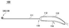
도 1을 참조하면, 본 발명의 일 실시예에 따른 전극 장치(100)는 본체(110), 전극 유닛(120), 전극 가이드(130)를 포함한다. 본체(110)는 일 방향으로 연장되는 샤프트(111)와, 샤프트(111)와 연결되어 시술자가 파지할 수 있도록 형성되는 그립부(112)와, 그립부(112)에 형성되어 전극 가이드(130)의 동작을 조작하는 가이드 조작부(113)와, 그립부(112)에 형성되어 전극 유닛(120)에 에너지 전달을 조작하는 전극 조작부(114)를 포함할 수 있다. 본체(110)의 내부에는 전극 유닛(120)과 전극 가이드(130)를 구동하고 제어하는 요소들이 배치될 수 있다.Referring to FIG. 1 , an
전극 유닛(120)은 샤프트(111)의 일 단부로부터 돌출되도록 형성되며, 시술자의 조작 등에 따라 체내의 관을 포함하는 조직(V)에 분포된 신경의 적어도 일부를 차단하거나 조절하도록 구성된다. 예를 들어, 전극 유닛(120)은 체내 관(V)의 외면을 감싸는 방법으로 접촉하여, 조직(V)에 분포된 신경에 전기 자극을 전달하거나 다양한 에너지를 전달하여 신경의 적어도 일부를 차단하거나 조절할 수 있다.The
도 2 를 참조하면, 전극 유닛(120)은 베이스 레이어(121), 전극 레이어(122) 및 센서부(123)를 포함할 수 있다. 본 발명에 따른 전극 장치(100)는 체내의 관 또는 관 형상의 조직(V)의 외면을 전극이 감싸 전극을 통해 에너지를 전달할 수 있고, 이를 위해 전극 유닛(120)은 가요성의 연성 회로 기판(FPCB)으로 이루어질 수 있다.Referring to FIG. 2 , the
전극 레이어(122)는 베이스 레이어(121) 상에 형성되는 것으로, 도 2의 실시예에서 전극 레이어(122)는 베이스 레이어(121) 상에서 서로 평행하게 연장되는 두 전극으로 구성될 수 있다. 본 실시예에서 베이스 레이어(121)와 전극 레이어(122)는 체내의 관(V) 등을 원주 방향으로 연장되어 감싸도록 구성될 수 있다.The
전극 레이어(122)는 신경을 차단(block or denervation)하거나 조절(control or modulation)하기 위하여, 예를 들어 스테인리스 스틸, 금 등과 같이 인체에 무해하며 전기를 전달할 수 있는 소재로 이루어질 수 있다. 또한, 전극 레이어(122)는 에너지 소스 생성기로부터의 다양한 타입의 에너지를 전달할 수 있다. 예를 들어, 고주파 에너지(radio-frequency(RF) energy), 전기 에너지, 레이어 에너지, 초음파 에너지(ultrasonic energy), 집속 초음파 에너지(high-intensity focused ultrasound energy), 극저온 에너지(cryogenic energy) 및 기타 열 에너지가 이용될 수 있다.The
또한, 전극 유닛(120)은 고주파 에너지 전달을 위한 연성 회로 기판(Flexible PCB), 초음파 에너지를 전달하기 위한 트랜스듀서, 높은 고전앞 에너지를 전달하기 위한 금속 전극 등으로 구현되어 신경을 손상시키기 위한 에너지를 전달할 수 있다.In addition, the
또한, 베이스 레이어(121) 상에는 센서부(123)가 형성될 수 있다. 일 예로, 센서부(123)는 체내의 관(V) 등에 접촉하여 온도를 측정하는 열전대(thermocouple)일 수 있고, 본 발명에 따른 전극 장치(100)에 의해 신경 절제 시술이 실시될 때, 센서부(123)는 시술 부위의 온도를 모니터링할 수 있다. 다른 예로, 센서부(123)는 관(V)의 신경의 신호를 측정할 수도 있다.Also, the
전극 가이드(130)는 전극 유닛(120)을 체내의 관(V)에 접촉시키는 기능을 수행한다. 전극 가이드(130)는 전극 유닛(120)과 결합되어 전극 유닛(120)을 체내의 관(V)에 접촉시키는 와인딩 상태로 변형된다.The
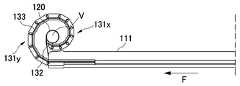
도 3a 내지 3c 및 도 4를 더 참조하면, 와인딩 상태로의 변형을 구현하기 위하여, 본 발명에 구비되는 전극 가이드(130)는 몸체부(131) 및 결합부(132)를 구비한다. 몸체부(131)는 와인딩 상태에서 전극 유닛(120)을 사이에 두고 체내의 관(V)의 둘레를 감싸도록 배치된다. 예를 들면, 도 2 및 3c에 도시된 상태가 와인딩 상태일 수 있다.Referring further to FIGS. 3A to 3C and 4 , in order to implement the deformation into the winding state, the
본 발명의 일 실시예에 따르면, 전극 가이드(130)는 전극 유닛(120)과 함께 샤프트(111)의 내부에 수용되어 있다가 시술을 위해 일 단부로부터 전방(F)을 향해 인출되면서 와인딩 상태로 변형될 수 있다. 도 3a 내지 3c에 도시한 것과 같이, 복수의 몸체부(131)는 순차적으로 인출되면서 일 측을 향해 이동되어 전체적으로 관(V)을 감싸는 와인딩 상태가 될 수 있다. 다만, 와인딩 상태에서 전극 가이드(130)는 관(V)의 외주면과 이격되게 위치되고, 전극 가이드(130)의 감겨진 내측에 배치되는 전극 유닛(120)이 관(V)의 외주면에 밀착될 수 있다.According to an embodiment of the present invention, the
본 발명의 일 실시예에 따르면, 몸체부(131)는 제1 몸체군(131x) 및 제2 몸체군(131y)을 포함할 수 있다. 도 3a 내지 4의 실시예에서, 제1 몸체군(131x)은 길이 방향으로 제1 길이를 갖고, 제2 몸체군(131y)은 제1 길이보다 긴 제2 길이를 가질 수 있다. 본 실시예에서, 제1 몸체군(131x)과 제2 몸체군(131y)은 각각 길이가 다른 예를 들면, 6개의 조인트를 포함할 수 있다.According to an embodiment of the present invention, the
이와 같은 길이의 차이에 따라, 와인딩 상태에서 제1 몸체군(131x)은 제1 곡률 반경을 형성하고, 제2 몸체군(131y)은 제1 곡률 반경보다 큰 제2 곡률 반경을 형성할 수 있다. 도 3c에서 확인할 수 있는 바와 같이, 상대적으로 짧은 길이를 갖는 조인트들(제1 몸체군(131x))이 작은 곡률 반경을 형성할 수 있고, 긴 길이를 갖는 조인트들(제2 몸체군(131y))이 큰 곡률 반경을 형성할 수 있다.According to this difference in length, in the winding state, the
더 구체적으로, 제1 곡률 반경을 형성하는 제1 몸체군(131x)은 결합부(132)에 가까운 측에, 제2 곡률 반경을 형성하는 제2 몸체군(131y)은 샤프트(111)에 가까운 측에 배치될 수 있다.More specifically, the
와인딩 상태에서 결합부(132)에 가까운 측에 배치된 몸체부(131)들이 더 작은 곡률 반경을 형성하게 되면, 도 3c에 보인 것과 같이 체내의 관(V)과 샤프트(111) 사이의 공간으로 결합부(132)가 진입되는 경로가 만들어질 수 있다. 예를 들면, 몸체부(131)를 포함하는 전극 가이드(130)가 전체적으로 나선형의 형상을 가질 수 있다.When the
이하에서는 도 5 및 6을 더 참조하여 결합부(132)에 대하여 설명한다. 결합부(132)는 몸체부(131)의 말단부에 연결되고 전극 유닛(120)의 단부가 고정되도록 형성된다. 결합부(132)는 전극 유닛(120)의 단부를 고정 또는 지지하기 위하여, 제1 클램핑 피스(132a) 및 제2 클램핑 피스(132b)를 포함할 수 있다. 도 5를 참조하면, 제1 클램핑 피스(132a)는 몸체부(131)에 고정되도록 형성될 수 있고, 제2 클램핑 피스(132b)는 제1 클램핑 피스(132a)와 전극 유닛(120)의 일부분을 사이에 두고 제1 클램핑 피스(132a)와 결합될 수 있다. 예를 들어, 제1 클램핑 피스(132a)는 전극 가이드(130)의 몸체부(131)와 가깝게 배치될 수 있고 제2 클램핑 피스(132b)는 전극 유닛(120)과 가깝게 배치될 수 있다.Hereinafter, the
이하, 제1 클램핑 피스(132a)와 제2 클램핑 피스(132b)간의 결합 구조를 구체적으로 살펴보면, 본 발명의 일 실시예에 따른 제1 클램핑 피스(132a) 및 제2 클램핑 피스(132b) 중 어느 하나는 일 방향으로 돌출되도록 형성되는 돌출부(132a1)를 구비할 수 있고, 제1 클램핑 피스(132a) 및 제2 클램핑 피스(132b) 중 다른 하나는 돌출부(132a1)에 대응하여 리세스되는 체결 홈(132b1)을 구비할 수 있다. 예를 들어, 도 5에 도시된 바와 같이, 제1 클램핑 피스(132a)에 돌출부(132a1)가 구비되면 제 2 클램핑 피스(132b)에는 체결 홈(132b1)이 구비될 수 있고, 이와 반대로 제2 클램핑 피스(132b)에 돌출부가 구비되면 제2 클램핑 피스(132b)에 체결홈이 구비될 수 있다.Hereinafter, referring to the coupling structure between the
제1 클램핑 피스(132a)에 구비된 돌출부(132a1)는 전극 유닛(120)을 관통하여 제2 클램핑 피스(132b)에 구비된 체결 홈(132b1)에 결합되어 체결될 수 있다.The protrusion 132a1 provided in the
또한, 전극 유닛(120)의 일부분에는 돌출부(132a1)가 관통하는 관통홀(120a)이 형성될 수 있다. 도 5를 참조하면, 관통홀(120a)은 전극 유닛(120)의 단부에 형성될 수 있고, 제1 클램핑 피스(132a)와 제2 클램핑 피스(132b) 사이에 형성될 수 있다. 예를 들어, 전극 유닛(120)의 일부분에 형성된 관통홀(120a)은 제1 클램핑 피스(132a)에 구비된 돌출부(132a1)를 관통시킬 수 있다.Also, a through
본 발명의 일 실시예에 따른 전극 유닛(120)은 제2 클램핑 피스(132b)를 감싸도록 연장되어 제1 클램핑 피스(132a)와 제2 클램핑 피스(132b) 사이에 삽입되어 있을 수 있다.The
또한, 본 발명의 일 실시예에 따른 전극 가이드(130)는, 도 3a 내지 도 5를 참조하면, 몸체부(131)를 와인딩 상태로 가이드하기 위하여 몸체부(131)를 관통하여 제2 클램핑 피스(132b)에 결합되는 조인트 와이어(133)를 더 포함할 수 있다. 예를 들어, 도 5의 실시예에서, 조인트 와이어(133)는 몸체부(131)를 순차적으로 관통하도록 형성될 수 있다. 조인트 와이어(133)는 전극 가이드(130)가 체내의 관(V)을 감싸는 형상으로 변형되는 것을 가이드할 수 있다.In addition, the
도 5를 참조하면, 제2 클램핑 피스(132b)는 조인트 와이어(133)의 단부가 삽입되도록 형성되는 와이어 홈(132b2) 및 와이어 홈(132b2)으로부터 조인트 와이어(133)의 단부가 이탈되는 것을 방지하도록 와이어 홈(132b2)의 일부를 폐쇄하는 고정 플레이트(132b3)를 구비할 수 있다.Referring to FIG. 5 , the
예를 들어, 와이어 홈(132b2)은 제2 클램핑 피스(132b)에 구비된 복수의 체결홈(132b1) 사이에서 조인트 와이어(133)의 단부를 수용하도록 형성될 수 있다. 와이어 홈(132b2)에 삽입된 조인트 와이어(133)의 단부는 와이어(133)보다 직경이 크거나 와이어(133)와 형상이 상이하여, 도 5 및 6을 참조하면, 고정 플레이트(132b3)에 걸려 와이어 홈(132b2)에서 이탈되지 않고 고정될 수 있다.For example, the wire groove 132b2 may be formed to accommodate the end of the
도 7을 참조하면, 본 발명의 일 실시예에 따른 전극 유닛(120)은 베이스 레이어(121), 전극 레이어(122) 및 탑 레이어(124)를 포함할 수 있다. 도 7의 실시예에서, 전극 유닛(120)은 베이스 레이어(121)와 베이스 레이어(121) 상에 배치되는 전극 레이어(122) 및 전극 레이어(122)를 사이에 두고 전극 레이어(122)의 일부를 오버랩하도록 배치되는 탑 레이어(124)를 포함할 수 있다. 한편 센서부(123)는 제1 금속(123a) 및 제2 금속(123b)으로 이루어진 열전대일 수 있고, 예를 들면, 구리(copper) 및 콘스탄탄(constantan)의 쌍으로 구성될 수 있다.Referring to FIG. 7 , the
본 발명의 일 실시예에 따른 전극 유닛(120)은 일부가 베이스 레이어(121)와 결합되고 다른 일부가 결합부(132)의 내부에 삽입 고정되는 보강 레이어(125)를 더 포함할 수 있다. 도 5의 실시예에서, 보강 레이어(125) 또한 관통홀(120a)을 구비할 수 있다.The
베이스 레이어(121) 및 탑 레이어(124) 중 적어도 하나는 결합부(132)의 일부(예를 들면, 제2 클램핑 피스(132b))를 감싸도록 연장되어 보강 레이어(125)의 다른 일부가 삽입되는 방향(도 5 및 6에서, 위에서 아래로)의 반대 방향으로(도 5 및 6에서, 아래에서 위로) 결합부(132) 내부에 삽입되어 고정될 수 있다. 이에 의해 전극 유닛(120)은 결합부(132)의 일부분(예를 들면, 제2 클램핑 피스(132b))을 양 방향으로 감싸도록 결합될 수 있다.At least one of the
본 발명의 전극 장치(100)에 따르면, 시술을 수행하도록 위치된 상태인 와인딩 상태에서 전극 가이드(130)와 전극 유닛(120)이 결합부(132)를 제외하고 대부분의 구간에서 서로 이격된 상태로 배치될 수 있다. 즉, 전극 유닛(120)과 전극 가이드(130)가 서로 이격된 공간이 공기 등 환경에 노출된 상태이므로, 전극 유닛(120)에서 에너지 전달 시 발생되는 열이 대류 열전달에 의해 용이하게 발산될 수 있다.According to the
또한, 본 발명의 전극 장치(100)에 따르면, 전극 유닛(120)과 전극 가이드(130)의 결합(조립) 지점을 최소화하면서도, 전극 유닛(120)이 전극 가이드(130)의 결합부(132)에 의해 견고하게 지지될 수 있다. 따라서, 장치의 내구성과 신뢰성이 확보될 수 있고, 전극 유닛(120)과 전극 가이드(130)의 조립이 용이한 이점이 있다.In addition, according to the
또한, 동력에 의해 와인딩 상태로 변형되는 전극 가이드(130)와, 체내의 관(V)에 밀착되는 전극 유닛(120)이 서로 별개로 구성되므로, 장치 동작 시 동력 전달에 의한 영향, 예를 들면, 진동이나 힘 등의 물리적인 에너지가 체내의 관에 전달되어 영향을 미치는 것을 억제할 수 있다.In addition, since the
전술한 본 발명의 설명은 예시를 위한 것이며, 본 발명이 속하는 기술분야의 통상의 지식을 가진 자는 본 발명의 기술적 사상이나 필수적인 특징을 변경하지 않고서 다른 구체적인 형태로 쉽게 변형이 가능하다는 것을 이해할 수 있을 것이다. 그러므로 이상에서 기술한 실시예들은 모든 면에서 예시적인 것이며 한정적이 아닌 것으로 이해해야만 한다. 예를 들어, 단일형으로 설명되어 있는 각 구성 요소는 분산되어 실시될 수도 있으며, 마찬가지로 분산된 것으로 설명되어 있는 구성 요소들도 결합된 형태로 실시될 수 있다.The description of the present invention described above is for illustration, and those of ordinary skill in the art to which the present invention pertains can understand that it can be easily modified into other specific forms without changing the technical spirit or essential features of the present invention. will be. Therefore, it should be understood that the embodiments described above are illustrative in all respects and not restrictive. For example, each component described as a single type may be implemented in a dispersed form, and likewise components described as distributed may be implemented in a combined form.
본 발명의 범위는 상기 상세한 설명보다는 후술하는 특허청구범위에 의하여 나타내어지며, 특허청구범위의 의미 및 범위 그리고 그 균등 개념으로부터 도출되는 모든 변경 또는 변형된 형태가 본 발명의 범위에 포함되는 것으로 해석되어야 한다.The scope of the present invention is indicated by the following claims rather than the above detailed description, and all changes or modifications derived from the meaning and scope of the claims and their equivalent concepts should be interpreted as being included in the scope of the present invention. do.
100: 전극 장치
110: 본체
120: 전극 유닛
130: 전극 가이드100: electrode device
110: body
120: electrode unit
130: electrode guide
Claims (12)
Translated fromKorean샤프트를 구비하는 본체;
상기 샤프트의 일 단부로부터 돌출되도록 형성되고, 상기 체내의 관의 적어도 일부의 신경을 차단 또는 조절하는 전극 유닛; 및
상기 전극 유닛을 상기 체내의 관에 접촉시키도록 와인딩 상태로 변형되는 전극 가이드를 포함하며,
상기 전극 가이드는,
상기 와인딩 상태에서 상기 전극 유닛과 이격되어 상기 관의 둘레를 감싸도록 형성되는 몸체부; 및
상기 몸체부의 말단부에 연결되고 상기 전극 유닛의 단부가 고정되도록 형성되는 결합부를 포함하는, 전극 장치.
In the electrode device for blocking or controlling nerves in the body,
a body having a shaft;
an electrode unit which is formed to protrude from one end of the shaft and blocks or controls nerves of at least a part of the tube in the body; and
and an electrode guide that is deformed into a winding state to bring the electrode unit into contact with the tube in the body,
The electrode guide,
a body portion spaced apart from the electrode unit in the winding state and formed to surround the circumference of the tube; and
And a coupling portion connected to the distal end of the body portion and formed so that the end of the electrode unit is fixed, the electrode device.
상기 결합부는,
상기 몸체부에 고정되도록 형성되는 제1 클램핑 피스; 및
상기 전극 유닛의 일부분을 사이에 두고 상기 제1 클램핑 피스와 결합되는 제2 클램핑 피스를 포함하는, 전극 장치.
The method of claim 1,
The coupling part,
a first clamping piece formed to be fixed to the body portion; and
and a second clamping piece coupled to the first clamping piece with a portion of the electrode unit interposed therebetween.
상기 제1 클램핑 피스 및 제2 클램핑 피스 중 어느 하나는, 일 방향으로 돌출되도록 형성되는 돌출부를 구비하고,
상기 제1 클램핑 피스 및 제2 클램핑 피스 중 다른 하나는, 상기 돌출부에 대응하여 리세스되는 체결 홈을 구비하고,
상기 전극 유닛의 일부분에는, 상기 돌출부가 관통하는 관통홀이 형성되는 것을 특징으로 하는, 전극 장치.
3. The method of claim 2,
Any one of the first clamping piece and the second clamping piece has a protrusion formed to protrude in one direction,
the other of the first clamping piece and the second clamping piece has a fastening groove recessed corresponding to the protrusion;
An electrode device, characterized in that a through hole through which the protrusion passes is formed in a portion of the electrode unit.
상기 전극 유닛은 상기 제2 클램핑 피스를 감싸도록 연장되어 상기 제1 클램핑 피스와 상기 제2 클램핑 피스 사이에 삽입되어 있는 것을 특징으로 하는, 전극 장치.
3. The method of claim 2,
The electrode unit extends to surround the second clamping piece and is inserted between the first clamping piece and the second clamping piece.
상기 전극 가이드는 상기 몸체부를 와인딩 상태로 가이드하기 위하여 상기 몸체부를 관통하여 상기 제2 클램핑 피스에 결합되는 조인트 와이어를 더 포함하고,
상기 제2 클램핑 피스는,
상기 조인트 와이어의 단부가 삽입되도록 형성되는 와이어 홈; 및
상기 와이어 홈으로부터 상기 조인트 와이어의 단부가 이탈되는 것을 방지하도록 상기 와이어 홈의 일부를 폐쇄하는 고정 플레이트를 구비하는, 전극 장치.
3. The method of claim 2,
The electrode guide further includes a joint wire coupled to the second clamping piece through the body to guide the body in a winding state,
The second clamping piece,
a wire groove formed so that an end of the joint wire is inserted; and
and a fixing plate for closing a part of the wire groove to prevent the end of the joint wire from being separated from the wire groove.
상기 전극 유닛은,
베이스 레이어;
상기 베이스 레이어 상에 배치되는 전극 레이어; 및
상기 전극 레이어를 사이에 두고 상기 전극 레이어의 일부를 오버랩하도록 배치되는 탑 레이어를 포함하는, 전극 장치.
The method of claim 1,
The electrode unit is
base layer;
an electrode layer disposed on the base layer; and
and a top layer disposed to overlap a portion of the electrode layer with the electrode layer interposed therebetween.
상기 결합부는,
상기 몸체부에 고정되도록 형성되는 제1 클램핑 피스; 및
상기 베이스 레이어 및 상기 탑 레이어 중 적어도 하나의 단부를 사이에 두고 상기 제1 클램핑 피스와 결합되는 제2 클램핑 피스를 포함하는, 전극 장치.
7. The method of claim 6,
The coupling part,
a first clamping piece formed to be fixed to the body portion; and
and a second clamping piece coupled to the first clamping piece with an end of at least one of the base layer and the top layer interposed therebetween.
상기 제1 클램핑 피스 및 제2 클램핑 피스 중 어느 하나는, 일 방향으로 돌출되도록 형성되는 돌출부를 구비하고,
상기 제1 클램핑 피스 및 제2 클램핑 피스 중 다른 하나는, 상기 돌출부에 대응하여 리세스되는 체결홈을 구비하고,
상기 베이스 레이어 및 상기 탑 레이어 중 적어도 하나에는, 상기 돌출부가 관통하는 관통홀이 형성되는 것을 특징으로 하는, 전극 장치.
8. The method of claim 7,
Any one of the first clamping piece and the second clamping piece has a protrusion formed to protrude in one direction,
the other of the first clamping piece and the second clamping piece has a fastening groove recessed corresponding to the protrusion;
At least one of the base layer and the top layer has a through hole through which the protrusion passes, the electrode device.
상기 베이스 레이어 및 상기 탑 레이어 중 적어도 하나는 상기 결합부의 일부를 감싸도록 연장되어 상기 결합부 내부에 삽입 고정되는 것을 특징으로 하는, 전극 장치.
7. The method of claim 6,
At least one of the base layer and the top layer extends to surround a portion of the coupling part, and is inserted and fixed inside the coupling part.
상기 전극 유닛은 일부가 상기 베이스 레이어와 결합되고 다른 일부가 상기 결합부의 내부에 삽입 고정되는 보강 레이어를 더 포함하는, 전극 장치.
7. The method of claim 6,
The electrode unit further comprises a reinforcing layer, part of which is coupled to the base layer and the other part is inserted and fixed inside the coupling part.
상기 베이스 레이어 및 상기 탑 레이어 중 적어도 하나는 상기 결합부의 일부를 감싸도록 연장되어, 상기 결합부의 다른 일부가 삽입되는 방향의 반대 방향으로 상기 결합부 내부에 삽입되어 고정되는 것을 특징으로 하는, 전극 장치.
11. The method of claim 10,
At least one of the base layer and the top layer extends to surround a part of the coupling part, and the other part of the coupling part is inserted and fixed inside the coupling part in a direction opposite to the insertion direction, the electrode device .
상기 전극 유닛은 상기 베이스 레이어 상에 배치되어 온도를 감지하도록 구성되는 센서부를 더 포함하는, 전극 장치.7. The method of claim 6,
The electrode unit further comprises a sensor unit disposed on the base layer and configured to sense a temperature.
Priority Applications (9)
| Application Number | Priority Date | Filing Date | Title |
|---|---|---|---|
| KR1020200167806AKR102296026B1 (en) | 2020-12-03 | 2020-12-03 | Electrode device |
| US17/921,717US20230240741A1 (en) | 2020-12-03 | 2020-12-10 | Electrode apparatus |
| PCT/KR2020/018057WO2022119032A1 (en) | 2020-12-03 | 2020-12-10 | Electrode device |
| BR112022021929ABR112022021929A2 (en) | 2020-12-03 | 2020-12-10 | ELECTRODE APPLIANCE |
| CA3177471ACA3177471A1 (en) | 2020-12-03 | 2020-12-10 | Electrode device |
| AU2020479941AAU2020479941B2 (en) | 2020-12-03 | 2020-12-10 | Electrode device |
| JP2022568995AJP7509451B2 (en) | 2020-12-03 | 2020-12-10 | Electrode device |
| CN202080100267.1ACN115484886B (en) | 2020-12-03 | 2020-12-10 | Electrode device |
| EP20964380.8AEP4115830A4 (en) | 2020-12-03 | 2020-12-10 | Electrode device |
Applications Claiming Priority (1)
| Application Number | Priority Date | Filing Date | Title |
|---|---|---|---|
| KR1020200167806AKR102296026B1 (en) | 2020-12-03 | 2020-12-03 | Electrode device |
Publications (1)
| Publication Number | Publication Date |
|---|---|
| KR102296026B1true KR102296026B1 (en) | 2021-09-02 |
Family
ID=77794102
Family Applications (1)
| Application Number | Title | Priority Date | Filing Date |
|---|---|---|---|
| KR1020200167806AActiveKR102296026B1 (en) | 2020-12-03 | 2020-12-03 | Electrode device |
Country Status (9)
| Country | Link |
|---|---|
| US (1) | US20230240741A1 (en) |
| EP (1) | EP4115830A4 (en) |
| JP (1) | JP7509451B2 (en) |
| KR (1) | KR102296026B1 (en) |
| CN (1) | CN115484886B (en) |
| AU (1) | AU2020479941B2 (en) |
| BR (1) | BR112022021929A2 (en) |
| CA (1) | CA3177471A1 (en) |
| WO (1) | WO2022119032A1 (en) |
Cited By (2)
| Publication number | Priority date | Publication date | Assignee | Title |
|---|---|---|---|---|
| WO2024210244A3 (en)* | 2023-04-04 | 2024-11-28 | 주식회사 딥큐어 | Electrode device for blocking or controlling nerves in body |
| WO2024210246A3 (en)* | 2023-04-04 | 2024-11-28 | 주식회사 딥큐어 | Rf energy generator, and method and computer program for outputting rf energy to electrode apparatus |
Families Citing this family (2)
| Publication number | Priority date | Publication date | Assignee | Title |
|---|---|---|---|---|
| KR102296027B1 (en)* | 2021-02-10 | 2021-09-01 | 주식회사 딥큐어 | Electrode apparatus for blocking or controlling nerve inside body |
| BR112023017451A2 (en)* | 2021-04-01 | 2023-09-26 | Deepqure Inc | Electrode apparatus for denervation or nerve modulation in vivo |
Citations (5)
| Publication number | Priority date | Publication date | Assignee | Title |
|---|---|---|---|---|
| US20020068868A1 (en)* | 1990-02-02 | 2002-06-06 | Thompson Russell B. | Assemblies for creating compound curves in distal catheter regions |
| JP2009513296A (en)* | 2005-11-09 | 2009-04-02 | コリア ユニバーシティ インダストリアル アンド アカデミック コラボレイション ファウンデーション | Radiation frequency electrode body for selective removal of body tissue |
| WO2009095689A1 (en)* | 2008-02-01 | 2009-08-06 | Barry Peter Liversidge | Power unit |
| JP2012525933A (en)* | 2009-05-07 | 2012-10-25 | セント・ジュード・メディカル・インコーポレーテッド | Irrigated ablation catheter with multi-segment ablation electrode |
| KR20130108401A (en) | 2010-10-25 | 2013-10-02 | 메드트로닉 아르디언 룩셈부르크 에스에이알엘 | Catheter appratuses having multi-electrode arrays for renal neuromodulation and associated systems and methods |
Family Cites Families (28)
| Publication number | Priority date | Publication date | Assignee | Title |
|---|---|---|---|---|
| US7527590B2 (en) | 2002-03-19 | 2009-05-05 | Olympus Corporation | Anastomosis system |
| US20040199052A1 (en)* | 2003-04-01 | 2004-10-07 | Scimed Life Systems, Inc. | Endoscopic imaging system |
| US9554691B2 (en) | 2004-04-21 | 2017-01-31 | Acclarent, Inc. | Endoscopic methods and devices for transnasal procedures |
| US8758349B2 (en)* | 2008-10-13 | 2014-06-24 | Dfine, Inc. | Systems for treating a vertebral body |
| JP5575777B2 (en) | 2008-09-30 | 2014-08-20 | ディファイン, インコーポレイテッド | System used to treat vertebral fractures |
| US8606368B2 (en)* | 2010-01-26 | 2013-12-10 | Olympus Corporation | Electrode unit, electrode system, electrode implanting apparatus, and electrode implanting system |
| EP2665448A4 (en)* | 2011-01-18 | 2017-08-02 | GT Urological, LLC | Vessel occlusive device and method of occluding a vessel |
| JP5253535B2 (en) | 2011-03-15 | 2013-07-31 | 日本ライフライン株式会社 | Electrode catheter |
| WO2013089988A1 (en)* | 2011-12-12 | 2013-06-20 | Neurostream Technologies G.P. | Compliant, reinforced electrode assembly and method of manufacture |
| WO2013091730A1 (en)* | 2011-12-23 | 2013-06-27 | Myopowers Medical Technologies Sa | Medical device comprising an artificial contractile structure |
| JP6320936B2 (en) | 2012-01-25 | 2018-05-09 | ボストン サイエンティフィック サイムド,インコーポレイテッドBoston Scientific Scimed,Inc. | Medical device with movable distal tool |
| SG11201407873RA (en)* | 2012-05-29 | 2014-12-30 | Autonomix Medical Inc | Endoscopic sympathectomy systems and methods |
| AU2014274903B2 (en) | 2013-06-05 | 2019-03-07 | Medtronic Ireland Manufacturing Unlimited Company | Modulation of targeted nerve fibers |
| JP6529971B2 (en)* | 2013-11-19 | 2019-06-12 | エシコン・インコーポレイテッドEthicon, Inc. | Thoracoscopic method for the treatment of bronchial disease |
| KR101761135B1 (en)* | 2014-07-11 | 2017-07-25 | (주)선메딕스 | Electrosurgical instrument |
| CA2969129A1 (en) | 2014-12-03 | 2016-06-09 | Metavention, Inc. | Systems and methods for modulating nerves or other tissue |
| US20160256218A1 (en)* | 2015-03-04 | 2016-09-08 | The Board Of Trustees Of The Leland Stanford Junior University | Perivascular Electroporation Device and Method for Extending Vascular Patency |
| AU2016275556A1 (en) | 2015-06-10 | 2017-12-14 | Cathrx Ltd | Double shape catheter |
| US10285752B2 (en)* | 2015-12-07 | 2019-05-14 | Biosense Webster (Israel) Ltd. | Multilayer split ablation electrode |
| US11051840B2 (en) | 2016-01-15 | 2021-07-06 | Ethicon Llc | Modular battery powered handheld surgical instrument with reusable asymmetric handle housing |
| US20190133681A1 (en)* | 2016-09-07 | 2019-05-09 | Chang Wook Jeong | Systems and methods for perivascular nerve denervation |
| US11259859B2 (en)* | 2016-09-07 | 2022-03-01 | Deepqure Inc. | Systems and methods for renal denervation |
| US10639462B2 (en)* | 2016-10-18 | 2020-05-05 | Acclarent, Inc. | Dilation system |
| BR112019013585A8 (en) | 2017-06-29 | 2023-03-07 | Univ Texas | ENDOLUMINAL SURGICAL APPLIANCE, ENDOLUMINAL SURGERY METHOD AND SURGICAL INSTRUMENT |
| ES2827175T3 (en)* | 2017-07-28 | 2021-05-20 | Galvani Bioelectronics Ltd | Neurostimulation electrode devices |
| US11647960B2 (en)* | 2017-08-28 | 2023-05-16 | Cortec Gmbh | Flexible neural electrode array |
| EP3723840B1 (en)* | 2017-12-13 | 2022-11-30 | Neuros Medical, Inc. | Nerve cuff deployment devices |
| KR102244131B1 (en)* | 2020-09-29 | 2021-04-23 | 주식회사 딥큐어 | Electrode apparatus for blocking or controlling nerve inside body |
- 2020
- 2020-12-03KRKR1020200167806Apatent/KR102296026B1/enactiveActive
- 2020-12-10AUAU2020479941Apatent/AU2020479941B2/enactiveActive
- 2020-12-10USUS17/921,717patent/US20230240741A1/enactivePending
- 2020-12-10WOPCT/KR2020/018057patent/WO2022119032A1/ennot_activeCeased
- 2020-12-10BRBR112022021929Apatent/BR112022021929A2/enunknown
- 2020-12-10CNCN202080100267.1Apatent/CN115484886B/enactiveActive
- 2020-12-10CACA3177471Apatent/CA3177471A1/enactivePending
- 2020-12-10EPEP20964380.8Apatent/EP4115830A4/enactivePending
- 2020-12-10JPJP2022568995Apatent/JP7509451B2/enactiveActive
Patent Citations (5)
| Publication number | Priority date | Publication date | Assignee | Title |
|---|---|---|---|---|
| US20020068868A1 (en)* | 1990-02-02 | 2002-06-06 | Thompson Russell B. | Assemblies for creating compound curves in distal catheter regions |
| JP2009513296A (en)* | 2005-11-09 | 2009-04-02 | コリア ユニバーシティ インダストリアル アンド アカデミック コラボレイション ファウンデーション | Radiation frequency electrode body for selective removal of body tissue |
| WO2009095689A1 (en)* | 2008-02-01 | 2009-08-06 | Barry Peter Liversidge | Power unit |
| JP2012525933A (en)* | 2009-05-07 | 2012-10-25 | セント・ジュード・メディカル・インコーポレーテッド | Irrigated ablation catheter with multi-segment ablation electrode |
| KR20130108401A (en) | 2010-10-25 | 2013-10-02 | 메드트로닉 아르디언 룩셈부르크 에스에이알엘 | Catheter appratuses having multi-electrode arrays for renal neuromodulation and associated systems and methods |
Cited By (2)
| Publication number | Priority date | Publication date | Assignee | Title |
|---|---|---|---|---|
| WO2024210244A3 (en)* | 2023-04-04 | 2024-11-28 | 주식회사 딥큐어 | Electrode device for blocking or controlling nerves in body |
| WO2024210246A3 (en)* | 2023-04-04 | 2024-11-28 | 주식회사 딥큐어 | Rf energy generator, and method and computer program for outputting rf energy to electrode apparatus |
Also Published As
| Publication number | Publication date |
|---|---|
| AU2020479941B2 (en) | 2024-03-21 |
| CN115484886B (en) | 2025-07-08 |
| JP2023525351A (en) | 2023-06-15 |
| JP7509451B2 (en) | 2024-07-02 |
| CN115484886A (en) | 2022-12-16 |
| AU2020479941A1 (en) | 2022-11-03 |
| EP4115830A1 (en) | 2023-01-11 |
| BR112022021929A2 (en) | 2022-12-13 |
| WO2022119032A1 (en) | 2022-06-09 |
| EP4115830A4 (en) | 2024-03-27 |
| US20230240741A1 (en) | 2023-08-03 |
| CA3177471A1 (en) | 2022-06-09 |
Similar Documents
| Publication | Publication Date | Title |
|---|---|---|
| KR102296026B1 (en) | Electrode device | |
| KR102462417B1 (en) | Electrode apparatus for blocking or controlling nerve inside body | |
| KR102347531B1 (en) | Electrode unit and electrode device comprising the same | |
| KR102296027B1 (en) | Electrode apparatus for blocking or controlling nerve inside body | |
| KR102296024B1 (en) | Electrode apparatus for blocking or controlling nerve inside body | |
| US20240366292A1 (en) | Electrode device for blocking or controlling nerves in body | |
| KR102398566B1 (en) | Electrode apparatus for blocking or controlling nerve inside body | |
| US20250082362A1 (en) | Electrode apparatus for nerve denervation or modulation in vivo | |
| AU2021460675B2 (en) | Electrode apparatus for nerve denervation or modulation in vivo |
Legal Events
| Date | Code | Title | Description |
|---|---|---|---|
| PA0109 | Patent application | Patent event code:PA01091R01D Comment text:Patent Application Patent event date:20201203 | |
| PA0201 | Request for examination | ||
| PA0302 | Request for accelerated examination | Patent event date:20201211 Patent event code:PA03022R01D Comment text:Request for Accelerated Examination Patent event date:20201203 Patent event code:PA03021R01I Comment text:Patent Application | |
| PE0902 | Notice of grounds for rejection | Comment text:Notification of reason for refusal Patent event date:20210222 Patent event code:PE09021S01D | |
| PE0701 | Decision of registration | Patent event code:PE07011S01D Comment text:Decision to Grant Registration Patent event date:20210602 | |
| GRNT | Written decision to grant | ||
| PR0701 | Registration of establishment | Comment text:Registration of Establishment Patent event date:20210825 Patent event code:PR07011E01D | |
| PR1002 | Payment of registration fee | Payment date:20210826 End annual number:3 Start annual number:1 | |
| PG1601 | Publication of registration |