KR102294675B1 - Haptic device for vehicle - Google Patents
Haptic device for vehicleDownload PDFInfo
- Publication number
- KR102294675B1 KR102294675B1KR1020200047334AKR20200047334AKR102294675B1KR 102294675 B1KR102294675 B1KR 102294675B1KR 1020200047334 AKR1020200047334 AKR 1020200047334AKR 20200047334 AKR20200047334 AKR 20200047334AKR 102294675 B1KR102294675 B1KR 102294675B1
- Authority
- KR
- South Korea
- Prior art keywords
- unit
- coil
- panel
- magnetic
- restoration
- Prior art date
- Legal status (The legal status is an assumption and is not a legal conclusion. Google has not performed a legal analysis and makes no representation as to the accuracy of the status listed.)
- Active
Links
Images


Classifications
- G—PHYSICS
- G06—COMPUTING OR CALCULATING; COUNTING
- G06F—ELECTRIC DIGITAL DATA PROCESSING
- G06F3/00—Input arrangements for transferring data to be processed into a form capable of being handled by the computer; Output arrangements for transferring data from processing unit to output unit, e.g. interface arrangements
- G06F3/01—Input arrangements or combined input and output arrangements for interaction between user and computer
- G06F3/016—Input arrangements with force or tactile feedback as computer generated output to the user
- G—PHYSICS
- G06—COMPUTING OR CALCULATING; COUNTING
- G06F—ELECTRIC DIGITAL DATA PROCESSING
- G06F3/00—Input arrangements for transferring data to be processed into a form capable of being handled by the computer; Output arrangements for transferring data from processing unit to output unit, e.g. interface arrangements
- G06F3/01—Input arrangements or combined input and output arrangements for interaction between user and computer
- G06F3/03—Arrangements for converting the position or the displacement of a member into a coded form
- G06F3/041—Digitisers, e.g. for touch screens or touch pads, characterised by the transducing means
Landscapes
- Engineering & Computer Science (AREA)
- General Engineering & Computer Science (AREA)
- Theoretical Computer Science (AREA)
- Human Computer Interaction (AREA)
- Physics & Mathematics (AREA)
- General Physics & Mathematics (AREA)
- User Interface Of Digital Computer (AREA)
Abstract
Translated fromKoreanDescription
Translated fromKorean본 발명은 차량용 햅틱장치에 관한 것으로서, 보다 상세하게는 운전자가 화면을 터치하여 인지하는 과정에서 외부 진동에 의한 노이즈 오류를 방지할 수 있는 차량용 햅틱장치에 관한 것이다.The present invention relates to a haptic device for a vehicle, and more particularly, to a haptic device for a vehicle capable of preventing a noise error caused by external vibration in the process of recognizing a driver by touching a screen.
일반적으로 햅틱(haptic)은 촉각을 통하여 사용자에게 정보를 전달하기 위한 연구 분야의 하나이다.In general, haptic is one of the research fields for transmitting information to a user through tactile sense.
종래에는 대부분의 정보 전달이 시각 또는 청각을 통하여 이루어졌으나, 컴퓨터 인터페이스 혹은 가상 환경의 발전에 따라 또 다른 감각 정보에 대한 사용자의 요구에 의해, 최근에는 햅틱이 적용된 제품이 출시되고 있다.Conventionally, most information is transmitted through sight or hearing. However, with the development of a computer interface or virtual environment, a user's request for other sensory information has recently led to the release of products to which haptics are applied.
한편, 차량에는 운전자 내지 탑승자의 안락한 주행을 위하여 여러개의 편의 기능이 증설됨에 따라 대화면이 사용되고, 사용자가 화면을 터치하여 원하는 기능을 수행할 수 있다.On the other hand, a large screen is used in the vehicle as a number of convenient functions are added for a comfortable driving of the driver or the passenger, and the user can perform a desired function by touching the screen.
이때, 햅틱 기능이 수행되면 운전자가 촉각을 통해 원하는 기능이 작동하는지 여부를 인지할 수 있다. 그러나, 차량 진동이 동반되면서 햅틱 기능이 정상적으로 이루어지지 못하고 노이즈를 동반하여 작동 오류가 발생하는 문제점이 있다. 따라서, 이를 개선할 필요성이 요청된다.In this case, when the haptic function is performed, the driver may recognize whether a desired function is operating through tactile sense. However, there is a problem in that the haptic function is not normally performed as the vehicle vibration is accompanied, and an operation error occurs due to noise. Therefore, there is a need to improve it.
본 발명의 배경기술은 대한민국 공개특허공보 제2015-0049722호(2015.05.08. 공개, 발명의 명칭 : 차량용 햅틱장치)에 게시되어 있다.Background art of the present invention is published in Republic of Korea Patent Publication No. 2015-0049722 (published on May 8, 2015, title of invention: haptic device for a vehicle).
본 발명은 상기와 같은 문제점들을 개선하기 위해 안출된 것으로서, 운전자가 화면을 터치하여 인지하는 과정에서 외부 진동에 의한 노이즈 오류를 방지할 수 있는 차량용 햅틱장치를 제공하는데 그 목적이 있다.An object of the present invention is to provide a haptic device for a vehicle capable of preventing a noise error due to external vibration in the process of recognizing that a driver touches and recognizes a screen.
본 발명에 따른 차량용 햅틱장치는: 차체에 장착되는 패널부; 상기 패널부에 설치되고, 사용자가 터치 가능한 디스플레이부; 상기 디스플레이부에 장착되는 코일부; 상기 패널부에 장착되고, 상기 코일부를 탄성 지지하는 복원부; 상기 패널부에 장착되고, 상기 코일부의 이동에 의한 자기력선 변화를 유도하는 자기부; 및 상기 패널부와 상기 자기부 사이에 배치되고, 상기 자기부의 진동을 흡수하는 댐퍼부;를 포함하는 것을 특징으로 한다.A haptic device for a vehicle according to the present invention includes: a panel unit mounted on a vehicle body; a display unit installed on the panel unit and capable of being touched by a user; a coil unit mounted on the display unit; a restoration unit mounted on the panel unit and elastically supporting the coil unit; a magnetic part mounted on the panel part and inducing a change in a magnetic force line by movement of the coil part; and a damper part disposed between the panel part and the magnetic part and absorbing the vibration of the magnetic part.
상기 코일부는 코일이 감기는 코일원통부; 상기 코일원통부에서 연장되는 하나 이상의 코일연장부; 및 상기 코일연장부의 단부에서 돌출되어 상기 복원부와 결합되는 코일보스부;를 포함하는 것을 특징으로 한다.The coil part includes a coil cylindrical part around which the coil is wound; one or more coil extensions extending from the coil cylinder; and a coil boss unit protruding from an end of the coil extension unit and coupled to the restoration unit.
상기 복원부는 상기 패널부에 지지되는 복원막대부; 상기 복원막대부에서 연장되고, 상기 코일부를 탄성 지지하는 복원지지부; 상기 복원막대부와 상기 복원지지부 중 어느 하나 이상을 상기 패널부에 고정시키는 복원고정부; 및 상기 복원지지부와 상기 코일부를 결합하는 복원결합부;를 포함하는 것을 특징으로 한다.The restoration unit includes a restoration bar supported by the panel unit; a restoration support unit extending from the restoration bar unit and elastically supporting the coil unit; a restoration fixing unit for fixing at least one of the restoration rod unit and the restoration support unit to the panel unit; and a restoration coupling unit for coupling the restoration support unit and the coil unit.
상기 자기부는 상기 패널부에 장착되는 자기지지부; 및 상기 자기지지부에 탄성 지지되고, 상기 코일부가 이동되면 자기력선 변화를 유도하는 자기유도부;를 포함하는 것을 특징으로 한다.The magnetic part may include a magnetic support part mounted on the panel part; and a magnetic induction part elastically supported by the magnetic support part and inducing a change in a magnetic force line when the coil part is moved.
상기 자기지지부는 상기 패널부를 통과하는 상기 자기유도부와 결합되고 탄성을 갖는 지지판부; 및 상기 지지판부를 상기 패널부에 고정시키는 지지체결부;를 포함하는 것을 특징으로 한다.The magnetic support portion includes a support plate portion coupled to the magnetic induction portion passing through the panel portion and having elasticity; and a support fastening part for fixing the support plate part to the panel part.
상기 댐퍼부는 상기 지지판부와 상기 패널부 사이에 배치되어 진동을 흡수하는 것을 특징으로 한다.The damper part is disposed between the support plate part and the panel part to absorb vibration.
상기 자기유도부는 상기 자기지지부와 결합되고, 전원이 인가되면 자기력이 발생되는 유도발생부; 및 상기 유도발생부를 감싸고, 상기 코일부의 삽입을 유도하는 유도가이드부;를 포함하는 것을 특징으로 한다.The magnetic induction unit is coupled to the magnetic support unit, the induction generating unit for generating a magnetic force when power is applied; and an induction guide unit surrounding the induction generating unit and guiding the insertion of the coil unit.
본 발명에 따른 차량용 햅틱장치는 자기부가 패널부에 장착되고, 자기부의 상방에 배치되는 코일부가 디스플레이부의 가압에 의해 이동되면서 햅틱을 구현하고, 패널부의 진동 및 소음을 억제할 수 있다.In the haptic device for a vehicle according to the present invention, the magnetic part is mounted on the panel part, and the coil part disposed above the magnetic part is moved by the pressure of the display part to implement haptics and suppress vibration and noise of the panel part.
도 1은 본 발명의 일 실시예에 따른 차량용 햅틱장치를 개략적으로 나타내는 단면도이다.
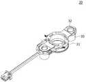
도 2는 본 발명의 일 실시예에 따른 코일부를 개략적으로 나타내는 도면이다.
도 3은 본 발명의 일 실시예에 따른 복원부를 개략적으로 나타내는 도면이다.
도 4는 본 발명의 일 실시예에 따른 자기부를 개략적으로 나타내는 도면이다.
도 5는 본 발명의 일 실시예에 따른 자기부가 패널부에 장착된 상태를 개략적으로 나타내는 도면이다.1 is a cross-sectional view schematically showing a haptic device for a vehicle according to an embodiment of the present invention.
2 is a view schematically showing a coil unit according to an embodiment of the present invention.
3 is a diagram schematically illustrating a restoration unit according to an embodiment of the present invention.
4 is a diagram schematically illustrating a magnetic unit according to an embodiment of the present invention.
5 is a diagram schematically illustrating a state in which a magnetic unit is mounted on a panel unit according to an embodiment of the present invention.
이하, 첨부된 도면들을 참조하여 본 발명에 따른 차량용 햅틱장치의 실시예를 설명한다. 이러한 과정에서 도면에 도시된 선들의 두께나 구성요소의 크기 등은 설명의 명료성과 편의상 과장되게 도시되어 있을 수 있다. 또한, 후술되는 용어들은 본 발명에서의 기능을 고려하여 정의된 용어들로서, 이는 사용자, 운용자의 의도 또는 관례에 따라 달라질 수 있다. 그러므로, 이러한 용어들에 대한 정의는 본 명세서 전반에 걸친 내용을 토대로 내려져야 할 것이다.Hereinafter, an embodiment of a haptic device for a vehicle according to the present invention will be described with reference to the accompanying drawings. In this process, the thickness of the lines or the size of the components shown in the drawings may be exaggerated for clarity and convenience of explanation. In addition, the terms to be described later are terms defined in consideration of functions in the present invention, which may vary according to intentions or customs of users and operators. Therefore, definitions of these terms should be made based on the content throughout this specification.
도 1은 본 발명의 일 실시예에 따른 차량용 햅틱장치를 개략적으로 나타내는 단면도이다. 도 1을 참조하면, 본 발명의 일 실시예에 따른 차량용 햅틱장치(1)는 패널부(10)와, 디스플레이부(20)와, 코일부(30)와, 복원부(40)와, 자기부(50)와, 댐퍼부(90)를 포함한다.1 is a cross-sectional view schematically showing a haptic device for a vehicle according to an embodiment of the present invention. Referring to FIG. 1 , a
패널부(10)는 차체에 장착된다. 일예로, 패널부(10)는 센터페시아에 장착될 수 있다.이러한 패널부(10)는 수지재질을 포함하여 이루어질 수 있다. 한편, 패널부(10)는 차체에 후크 결합되거나 나사 결합될 수 있다.The
디스플레이부(20)는 패널부(10)에 설치되고, 사용자가 터치 가능하다. 일예로, 디스플레이부(20)는 패널부(10)의 전면부를 커버하고, 외부로 노출되어 탑승자가 터치할 수 있다.The
코일부(30)는 디스플레이부(20)에 장착되고, 패널부(10)에 장착된 복원부(40)는 코일부(30)를 탄성 지지한다. 이러한 복원부(40)는 사용자가 디스플레이부(20)를 가압하더라도 자체 복원력에 의해 디스플레이부(20)를 원위치로 복귀시킬 수 있다.The
자기부(50)는 패널부(10)에 장착되고, 코일부(30)의 이동에 의한 자기력선 변화를 유도한다. 일예로, 자기부(50)는 위치가 고정되고, 디스플레이부(20)의 가압시 디스플레이부(20)에 장착된 코일부(30)가 자기부(50)를 향하여 이동될 수 있다. 그리고, 고정된 자기부(50)가 코일부(30)를 관통하는 과정을 반복하면, 자기력선 변화로 인해 유도전류가 발생할 수 있다. 발생된 유도전류는 제어부에 입력되고, 자기부(50)에 전원이 인가되면 기전력에 의해 코일부(30)를 움직여 피드백을 구현할 수 있다.The
한편, 자기부(50)의 하방에는 기판부(100)가 배치될 수 있다. 이러한 기판부(100)는 패널부(10)에 장착되고, 코일부(30) 및 자기부(50)와 전기적으로 연결되어 신호를 송수신하고, 햅틱 제어를 실시할 수 있다.Meanwhile, the
댐퍼부(90)는 패널부(10)와 자기부(50) 사이에 배치되고, 자기부(50)의 진동을 흡수한다. 일예로, 댐퍼부(90)는 충격 흡수가 가능한 재질을 포함하여 이루어지고, 크기나 개수는 설계 상황에 따라 적절하게 조절될 수 있다. 이러한 댐퍼부(90)는 양면테이프 또는 접착제를 사용하여 패널부(10) 또는 자기부(50)에 부착될 수 있으며, 자기부(50)의 과도한 진동에 의한 소음을 완화할 수 있다.The
도 2는 본 발명의 일 실시예에 따른 코일부를 개략적으로 나타내는 도면이다. 도 2를 참조하면, 본 발명의 일 실시예에 따른 코일부(30)는 코일원통부(31)와, 코일연장부(32)와, 코일보스부(33)를 포함한다. 이러한 코일부(30)는 일체로 성형될 수 있다.2 is a view schematically showing a coil unit according to an embodiment of the present invention. Referring to FIG. 2 , the
코일원통부(31)는 원통 형상을 하여 외주면에 코일이 감긴다. 일예로, 코일원통부(31)에는 케이블이 연결되어 전원이 인가되거나 신호가 송수신될 수 있다.The coil
하나 이상의 코일연장부(32)는 코일원통부(31)에서 연장된다. 일예로, 코일연장부(32)는 코일원통부(31)의 상측 외주면에서 2개가 일직선상으로 연장될 수 있다.One or more
코일보스부(33)는 코일연장부(32)의 단부에서 돌출되어 복원부(40)와 결합된다. 일예로, 코일보스부(33)에는 코일연장부(32)에서 하방으로 돌출되되 내측에 공간이 형성되고, 디스플레이부(20)에 형성되는 돌기가 코일보스부(33)에 삽입되어 복원부(40)와 결합될 수 있다.The
도 3은 본 발명의 일 실시예에 따른 복원부를 개략적으로 나타내는 도면이다. 도 3을 참조하면, 본 발명의 일 실시예에 따른 복원부(40)는 복원막대부(41)와, 복원지지부(42)와, 복원고정부(43)와, 복원결합부(44)를 포함한다.3 is a diagram schematically illustrating a restoration unit according to an embodiment of the present invention. Referring to FIG. 3 , the
복원막대부(41)는 패널부(10)에 지지된다. 일예로, 복원막대부(41)는 패널부(10)의 저면에 밀착되되, 패널부(10)에 형성되는 패널유도돌기(11)가 복원막대부(41)에 삽입되어 장착 위치를 유도할 수 있다. 그 외, 복원막대부(41)는 패널부(10)의 상측면에 밀착되어 패널부(10)와 디스플레이부(20) 사이에 배치될 수 있다.The
복원지지부(42)는 복원막대부(41)에서 연장되고, 코일부(30)를 탄성 지지한다. 일예로, 복원지지부(42)는 복원막대부(41)의 양단부에서 연장되고 패널부(10)에 형성되는 패널장착홀부(12)에 단부가 배치되어 코일보스부(33)를 지지할 수 있다. 이러한 복원지지부(42)는 자체 길이로 인해 탄성을 가지며 코일보스부(33)에 대한 외력이 제거되면 코일보스부(33)를 원위치로 복귀시킬 수 있다.The
복원결합부(43)는 복원막대부(41)와 복원지지부(42) 중 어느 하나 이상을 패널부(10)에 고정시킨다. 일예로, 복원결합부(43)는 복원막대부(41) 자체 또는 복원막대부(41)에 근접한 복원지지부(42)를 관통하여 패널부(10)에 나사 결합될 수 있다.The
복원결합부(44)는 복원지지부(42)와 코일부(30)를 결합한다. 일예로, 복원결합부(44)는 복원지지부(42)의 단부를 관통하여 코일보스부(33) 및 코일보스부(33)에 삽입된 디스플레이부(20)와 나사 결합될 수 있다. 이로 인해 디스플레이부(20)의 가압시 코일부(30)가 하방 이동되더라도 복원부(40)에 의해 원위치로 신속하게 복귀할 수 있다.The
도 4는 본 발명의 일 실시예에 따른 자기부를 개략적으로 나타내는 도면이고, 도 5는 본 발명의 일 실시예에 따른 자기부가 패널부에 장착된 상태를 개략적으로 나타내는 도면이다. 도 4와 도 5를 참조하면, 본 발명의 일 실시예에 따른 자기부(50)는 자기지지부(60)와 자기유도부(70)를 포함한다.4 is a diagram schematically illustrating a magnetic unit according to an embodiment of the present invention, and FIG. 5 is a diagram schematically illustrating a state in which a magnetic unit is mounted to a panel unit according to an embodiment of the present invention. 4 and 5 , the
자기지지부(60)는 패널부(10)에 장착되고, 자체 탄성에 의해 진동 소음을 억제할 수 있다. 그리고, 자기유도부(70)는 자기지지부(60)에 탄성 지지되고, 코일부(30)가 이동되면 코일부(30)에 삽입되어 자기력선 변화를 유도한다.The self-supporting
본 발명의 일 실시예에 따른 자기지지부(60)는 지지판부(61)와 지지체결부(62)를 포함한다. 이러한 자기지지부(60)는 자체 형상에 의해 탄성을 가지며, 카운터매스로 작용하여 진동하고, 패널부(10)로 전달되는 진동에너지를 상쇄시킬 수 있다.The self-supporting
지지판부(61)는 패널부(10)를 통과하는 자기유도부(70)와 결합되고 탄성을 갖는다. 일예로, 지지판부(61)는 패널장착홀부(12)를 가로지르는 판센터부(611)와, 판센터부(611)의 양단부에서 연장되고 패널부(10)에 지지되는 판사이드부(612)를 포함할 수 있다. 판센터부(611)의 중앙부는 자기유도부(70)와 결합되고, 판사이드부(612)는 패널부(10)의 저면에 밀착되되, 패널부(10)에 형성되는 패널장착돌기(13)가 판사이드부(612)에 삽입되어 장착 위치를 유도할 수 있다.The
지지체결부(62)는 지지판부(61)를 패널부(10)에 고정시킨다. 일예로, 판사이드부(612)의 양단부에 패널장착돌기(13)가 삽입되고, 지지체결부(62)는 패널장착돌기(13)에 근접하는 판사이드부(612)를 통해 패널부(10)와 나사 결합될 수 있다.The
한편, 댐퍼부(90)는 저면이 지지판부(61)에 밀착되고, 상면이 패널부(10)에 밀착되어 지지판부(61)의 과도한 진동에 의한 소음을 완화할 수 있다. 이때, 댐퍼부(90)는 판센터부(611)와 지지체결부(62) 사이에 배치되어 지지판부(61)에서 발생되는 진동을 효과적으로 차단할 수 있다.Meanwhile, the
본 발명의 일 실시예에 따른 자기유도부(70)는 유도발생부(71)와 유도가이드부(72)를 포함한다.The
유도발생부(71)는 자기지지부(60)와 결합되고, 전원이 인가되면 자기력이 발생된다. 일예로, 유도발생부(71)는 코일원통부(31)에 삽입 가능한 직경을 갖는 원기둥 형상을 할 수 있다. 이러한 유도발생부(71)는 지지판부(61)와 결합되고 코일부(30)의 이동에 의해 햅틱 진동을 유발할 수 있다.The
유도가이드부(72)는 유도발생부(71)를 감싸고, 코일부(30)의 삽입을 유도한다. 일예로, 유도가이드부(72)는 유도발생부(71)의 저면을 커버하는 원판 형상을 하는 가이드하판부(721)와, 가이드하판부(721)의 가장자리에서 돌출되어 유도발생부(721)의 측면을 커버하는 가이드측판부(722)를 포함할 수 있다. 가이드측판부(722)의 내경은 코일원통부(31)의 외경보다 더 크게 형성되어, 코일원통부(31)는 유도발생부(71)와 가이드측판부(722) 사이 공간으로 이동될 수 있다.The induction guide
상기와 같은 구조를 갖는 본 발명의 일 실시예에 따른 차량용 햅틱장치의 조립 및 작동을 설명하면 다음과 같다.The assembly and operation of the haptic device for a vehicle according to an embodiment of the present invention having the above structure will be described as follows.
자기발생부(70)와 결합된 자기지지부(60)를 패널부(10)에 장착하고, 패널부(10)에 결합되는 디스플레이부(20)에는 코일부(30)를 설치한다. 이때, 코일부(30)는 자기발생부(70)와 마주보도록 배치되고, 패널부(10)에 장착되는 복원부(40)는 코일부(30)를 탄성 지지한다.The
상기한 상태에서 사용자가 디스플레이부(20)를 가압하면 코일부(30)가 자기발생부(70)에 근접되어 유도전류가 생성되고, 기판부(100)의 제어로 코일부(30)가 이동되어 햅틱 피드백이 구현된다.When the user presses the
한편, 종래에는 디스플레이부(20)에 자기발생부(70)가 장착되었으나, 본 발명에서는 디스플레이부(20)에 코일부(30)가 장착된다. 이때, 코일부(30)는 자기발생부(70) 보다 가벼우므로, 디스플레이부(20)에 자기발생부(70)가 장착되는 것 보다 디스플레이부(20)에 코일부(30)가 장착되는 구조가 소음 및 진동을 억제할 수 있다.Meanwhile, in the related art, the
그리고, 패널부(10)에 장착되는 지지판부(61)는 햅틱 구현시 패널부(10)로 전달되는 진동에너지를 흡수할 수 있고, 지지판부(61)에 부착되는 댐퍼부(90)는 지지판부(61)의 과도한 진동에너지를 흡수할 수 있다.In addition, the
본 발명의 일 실시예에 따른 차량용 햅틱장치는 자기부(50)가 패널부(10)에 장착되고, 자기부(50)의 상방에 배치되는 코일부(30)가 디스플레이부(20)의 가압에 의해 이동되면서 햅틱을 구현하고, 패널부(10)의 진동 및 소음을 억제할 수 있다.In the haptic device for a vehicle according to an embodiment of the present invention, the
본 발명은 도면에 도시된 실시예를 참고로 하여 설명되었으나, 이는 예시적인 것에 불과하며, 당해 기술이 속하는 분야에서 통상의 지식을 가진 자라면 이로부터 다양한 변형 및 균등한 타 실시예가 가능하다는 점을 이해할 것이다. 따라서, 본 발명의 진정한 기술적 보호범위는 아래의 특허청구범위에 의해서 정하여져야 할 것이다.Although the present invention has been described with reference to the embodiment shown in the drawings, this is merely exemplary, and it is understood that various modifications and equivalent other embodiments are possible by those of ordinary skill in the art. will understand Accordingly, the true technical protection scope of the present invention should be defined by the following claims.
10 : 패널부 20 : 디스플레이부
30 : 코일부 31 : 코일원통부
32 : 코일연장부 33 : 코일보스부
40 : 복원부 41 : 복원막대부
42: 복원지지부 43 : 복원고정부
44 : 복원결합부 50 : 자기부
60 : 자기지지부 61 : 지지판부
62 : 지지체결부 70 : 자기유도부
71 : 유도발생부 72 : 유도가이드부
90 : 댐퍼부10: panel unit 20: display unit
30: coil part 31: coil cylindrical part
32: coil extension 33: coil boss
40: restoration unit 41: restoration bar unit
42: restoration support 43: restoration fixing unit
44: restoration coupling part 50: magnetic part
60: magnetic support part 61: support plate part
62: support fastening part 70: magnetic induction part
71: induction generating unit 72: induction guide unit
90: damper part
Claims (7)
Translated fromKorean상기 패널부에 설치되고, 사용자가 터치 가능한 디스플레이부;
상기 디스플레이부에 장착되는 코일부;
상기 패널부에 장착되고, 상기 코일부를 탄성 지지하는 복원부;
상기 패널부에 장착되고, 상기 코일부의 이동에 의한 자기력선 변화를 유도하는 자기부; 및
상기 패널부와 상기 자기부 사이에 배치되고, 상기 자기부의 진동을 흡수하는 댐퍼부;를 포함하는 것을 특징으로 하는 차량용 햅틱장치.
a panel unit mounted on the vehicle body;
a display unit installed on the panel unit and capable of being touched by a user;
a coil unit mounted on the display unit;
a restoration unit mounted on the panel unit and elastically supporting the coil unit;
a magnetic part mounted on the panel part and inducing a change in a magnetic force line by movement of the coil part; and
and a damper part disposed between the panel part and the magnetic part and absorbing the vibration of the magnetic part.
코일이 감기는 코일원통부;
상기 코일원통부에서 연장되는 하나 이상의 코일연장부; 및
상기 코일연장부의 단부에서 돌출되어 상기 복원부와 결합되는 코일보스부;를 포함하는 것을 특징으로 하는 차량용 햅틱장치.
According to claim 1, wherein the coil unit
Coil cylindrical portion around which the coil is wound;
one or more coil extensions extending from the coil cylinder; and
and a coil boss unit protruding from an end of the coil extension unit and coupled to the restoration unit.
상기 패널부에 지지되는 복원막대부;
상기 복원막대부에서 연장되고, 상기 코일부를 탄성 지지하는 복원지지부;
상기 복원막대부와 상기 복원지지부 중 어느 하나 이상을 상기 패널부에 고정시키는 복원고정부; 및
상기 복원지지부와 상기 코일부를 결합하는 복원결합부;를 포함하는 것을 특징으로 하는 차량용 햅틱장치.
According to claim 1, wherein the restoration unit
a restoration bar part supported on the panel part;
a restoration support unit extending from the restoration bar unit and elastically supporting the coil unit;
a restoration fixing unit for fixing at least one of the restoration rod unit and the restoration support unit to the panel unit; and
The haptic device for a vehicle comprising a; a restoration coupling unit for coupling the restoration support unit and the coil unit.
상기 패널부에 장착되는 자기지지부; 및
상기 자기지지부에 탄성 지지되고, 상기 코일부가 이동되면 자기력선 변화를 유도하는 자기유도부;를 포함하는 것을 특징으로 하는 차량용 햅틱장치.
According to claim 1, wherein the magnetic portion
a magnetic support unit mounted on the panel unit; and
and a magnetic induction part elastically supported by the magnetic support part and inducing a change in a magnetic force line when the coil part is moved.
상기 패널부를 통과하는 상기 자기유도부와 결합되고 탄성을 갖는 지지판부; 및
상기 지지판부를 상기 패널부에 고정시키는 지지체결부;를 포함하는 것을 특징으로 하는 차량용 햅틱장치.
5. The method of claim 4, wherein the self-supporting portion
a support plate portion coupled to the magnetic induction portion passing through the panel portion and having elasticity; and
and a support fastening part for fixing the support plate part to the panel part.
상기 댐퍼부는 상기 지지판부와 상기 패널부 사이에 배치되어 진동을 흡수하는 것을 특징으로 하는 차량용 햅틱장치.
6. The method of claim 5,
The haptic device for a vehicle, characterized in that the damper part is disposed between the support plate part and the panel part to absorb vibration.
상기 자기지지부와 결합되고, 전원이 인가되면 자기력이 발생되는 유도발생부; 및
상기 유도발생부를 감싸고, 상기 코일부의 삽입을 유도하는 유도가이드부;를 포함하는 것을 특징으로 하는 차량용 햅틱장치.
5. The method of claim 4, wherein the magnetic induction part
an induction generating unit coupled to the magnetic support unit and generating a magnetic force when power is applied; and
and an induction guide part surrounding the induction generating part and guiding the insertion of the coil part.
Priority Applications (1)
| Application Number | Priority Date | Filing Date | Title |
|---|---|---|---|
| KR1020200047334AKR102294675B1 (en) | 2020-04-20 | 2020-04-20 | Haptic device for vehicle |
Applications Claiming Priority (1)
| Application Number | Priority Date | Filing Date | Title |
|---|---|---|---|
| KR1020200047334AKR102294675B1 (en) | 2020-04-20 | 2020-04-20 | Haptic device for vehicle |
Publications (1)
| Publication Number | Publication Date |
|---|---|
| KR102294675B1true KR102294675B1 (en) | 2021-08-27 |
Family
ID=77504316
Family Applications (1)
| Application Number | Title | Priority Date | Filing Date |
|---|---|---|---|
| KR1020200047334AActiveKR102294675B1 (en) | 2020-04-20 | 2020-04-20 | Haptic device for vehicle |
Country Status (1)
| Country | Link |
|---|---|
| KR (1) | KR102294675B1 (en) |
Citations (6)
| Publication number | Priority date | Publication date | Assignee | Title |
|---|---|---|---|---|
| KR20110104265A (en)* | 2010-03-16 | 2011-09-22 | 삼성전기주식회사 | Electronic device having a haptic feedback device with a sense of click |
| KR20140026893A (en)* | 2012-08-23 | 2014-03-06 | 현대모비스 주식회사 | Display apparatus |
| KR20150049722A (en)* | 2013-10-30 | 2015-05-08 | 현대모비스 주식회사 | Haptic device for vehicle |
| KR20190037272A (en)* | 2016-08-09 | 2019-04-05 | 베르-헬라 테르모콘트롤 게엠베하 | Operating units for automotive components, especially for devices |
| KR20190135887A (en)* | 2018-05-29 | 2019-12-09 | 주식회사 씨케이머티리얼즈랩 | Active button actuator, active button actuator feedback system comprising thereof and controlling method thereof |
| KR20190142214A (en)* | 2018-06-15 | 2019-12-26 | 임머숀 코퍼레이션 | Damping for a haptic actuator |
- 2020
- 2020-04-20KRKR1020200047334Apatent/KR102294675B1/enactiveActive
Patent Citations (6)
| Publication number | Priority date | Publication date | Assignee | Title |
|---|---|---|---|---|
| KR20110104265A (en)* | 2010-03-16 | 2011-09-22 | 삼성전기주식회사 | Electronic device having a haptic feedback device with a sense of click |
| KR20140026893A (en)* | 2012-08-23 | 2014-03-06 | 현대모비스 주식회사 | Display apparatus |
| KR20150049722A (en)* | 2013-10-30 | 2015-05-08 | 현대모비스 주식회사 | Haptic device for vehicle |
| KR20190037272A (en)* | 2016-08-09 | 2019-04-05 | 베르-헬라 테르모콘트롤 게엠베하 | Operating units for automotive components, especially for devices |
| KR20190135887A (en)* | 2018-05-29 | 2019-12-09 | 주식회사 씨케이머티리얼즈랩 | Active button actuator, active button actuator feedback system comprising thereof and controlling method thereof |
| KR20190142214A (en)* | 2018-06-15 | 2019-12-26 | 임머숀 코퍼레이션 | Damping for a haptic actuator |
Similar Documents
| Publication | Publication Date | Title |
|---|---|---|
| JP6746576B2 (en) | Haptic feedback device for motor vehicles | |
| JP6707599B2 (en) | Touch interface module | |
| JP6078935B2 (en) | Electronics | |
| KR102349641B1 (en) | Touch panel controller assembly structure of vehicle | |
| US10152132B2 (en) | Method and apparatus for enabling heavy floating touchscreen haptics assembles and passive braking system | |
| JP5810318B2 (en) | Electronics | |
| EP3382515B1 (en) | Tactile presentation device | |
| JP2011501296A (en) | Digital envelope modulator for haptic feedback device | |
| JP2019109673A (en) | Input device | |
| JP2014146174A (en) | Touch panel support | |
| KR102294675B1 (en) | Haptic device for vehicle | |
| US12214663B2 (en) | Input assembly with active haptic feedback and backlit display region | |
| KR20210141877A (en) | Touch panel controller assembly structure of vehicle | |
| KR102628953B1 (en) | Touch panel controller assembly structure of vehicle | |
| CN206932341U (en) | A kind of band touches the vehicle audio panel of vibrating function | |
| CN207488950U (en) | Display device with touch-induction-type transparent display element | |
| CN222088041U (en) | Haptic displays for vehicles | |
| CN214069904U (en) | Suspension mechanism for touch switch and touch switch comprising same | |
| KR102054140B1 (en) | Haptic device for vehicle | |
| JP2015102953A (en) | Operation input device | |
| US20220337245A1 (en) | Haptic reactive electrical switch | |
| CN214775390U (en) | Switch integrated on steering wheel framework and provided with vibration feedback | |
| CN215773078U (en) | Vibration feedback device for touch switch and touch switch comprising same | |
| KR20230077524A (en) | Vibration Generator | |
| CN118732882A (en) | Touch panels, touch buttons and automobiles |
Legal Events
| Date | Code | Title | Description |
|---|---|---|---|
| PA0109 | Patent application | St.27 status event code:A-0-1-A10-A12-nap-PA0109 | |
| PA0201 | Request for examination | St.27 status event code:A-1-2-D10-D11-exm-PA0201 | |
| PE0701 | Decision of registration | St.27 status event code:A-1-2-D10-D22-exm-PE0701 | |
| GRNT | Written decision to grant | ||
| PR0701 | Registration of establishment | St.27 status event code:A-2-4-F10-F11-exm-PR0701 | |
| PR1002 | Payment of registration fee | St.27 status event code:A-2-2-U10-U11-oth-PR1002 Fee payment year number:1 | |
| PG1601 | Publication of registration | St.27 status event code:A-4-4-Q10-Q13-nap-PG1601 | |
| PR1001 | Payment of annual fee | St.27 status event code:A-4-4-U10-U11-oth-PR1001 Fee payment year number:4 | |
| PN2301 | Change of applicant | St.27 status event code:A-5-5-R10-R11-asn-PN2301 | |
| PN2301 | Change of applicant | St.27 status event code:A-5-5-R10-R13-asn-PN2301 St.27 status event code:A-5-5-R10-R11-asn-PN2301 | |
| PN2301 | Change of applicant | St.27 status event code:A-5-5-R10-R11-asn-PN2301 | |
| PN2301 | Change of applicant | St.27 status event code:A-5-5-R10-R14-asn-PN2301 | |
| PR1001 | Payment of annual fee | St.27 status event code:A-4-4-U10-U11-oth-PR1001 Fee payment year number:5 |