KR102292632B1 - Vibration Damping System by Hanging Vibrating Source and a Compressor Using the Same - Google Patents
Vibration Damping System by Hanging Vibrating Source and a Compressor Using the SameDownload PDFInfo
- Publication number
- KR102292632B1 KR102292632B1KR1020200032716AKR20200032716AKR102292632B1KR 102292632 B1KR102292632 B1KR 102292632B1KR 1020200032716 AKR1020200032716 AKR 1020200032716AKR 20200032716 AKR20200032716 AKR 20200032716AKR 102292632 B1KR102292632 B1KR 102292632B1
- Authority
- KR
- South Korea
- Prior art keywords
- string
- shell
- compressor
- connection part
- assembly
- Prior art date
- Legal status (The legal status is an assumption and is not a legal conclusion. Google has not performed a legal analysis and makes no representation as to the accuracy of the status listed.)
- Active
Links
Images


Classifications
- F—MECHANICAL ENGINEERING; LIGHTING; HEATING; WEAPONS; BLASTING
- F04—POSITIVE - DISPLACEMENT MACHINES FOR LIQUIDS; PUMPS FOR LIQUIDS OR ELASTIC FLUIDS
- F04B—POSITIVE-DISPLACEMENT MACHINES FOR LIQUIDS; PUMPS
- F04B53/00—Component parts, details or accessories not provided for in, or of interest apart from, groups F04B1/00 - F04B23/00 or F04B39/00 - F04B47/00
- F04B53/001—Noise damping
- F04B53/003—Noise damping by damping supports
- F—MECHANICAL ENGINEERING; LIGHTING; HEATING; WEAPONS; BLASTING
- F04—POSITIVE - DISPLACEMENT MACHINES FOR LIQUIDS; PUMPS FOR LIQUIDS OR ELASTIC FLUIDS
- F04B—POSITIVE-DISPLACEMENT MACHINES FOR LIQUIDS; PUMPS
- F04B39/00—Component parts, details, or accessories, of pumps or pumping systems specially adapted for elastic fluids, not otherwise provided for in, or of interest apart from, groups F04B25/00 - F04B37/00
- F04B39/0027—Pulsation and noise damping means
- F04B39/0044—Pulsation and noise damping means with vibration damping supports
- F—MECHANICAL ENGINEERING; LIGHTING; HEATING; WEAPONS; BLASTING
- F04—POSITIVE - DISPLACEMENT MACHINES FOR LIQUIDS; PUMPS FOR LIQUIDS OR ELASTIC FLUIDS
- F04B—POSITIVE-DISPLACEMENT MACHINES FOR LIQUIDS; PUMPS
- F04B39/00—Component parts, details, or accessories, of pumps or pumping systems specially adapted for elastic fluids, not otherwise provided for in, or of interest apart from, groups F04B25/00 - F04B37/00
- F04B39/02—Lubrication
- F04B39/0223—Lubrication characterised by the compressor type
- F04B39/023—Hermetic compressors
- F—MECHANICAL ENGINEERING; LIGHTING; HEATING; WEAPONS; BLASTING
- F04—POSITIVE - DISPLACEMENT MACHINES FOR LIQUIDS; PUMPS FOR LIQUIDS OR ELASTIC FLUIDS
- F04B—POSITIVE-DISPLACEMENT MACHINES FOR LIQUIDS; PUMPS
- F04B39/00—Component parts, details, or accessories, of pumps or pumping systems specially adapted for elastic fluids, not otherwise provided for in, or of interest apart from, groups F04B25/00 - F04B37/00
- F04B39/12—Casings; Cylinders; Cylinder heads; Fluid connections
- F04B39/121—Casings
- F—MECHANICAL ENGINEERING; LIGHTING; HEATING; WEAPONS; BLASTING
- F04—POSITIVE - DISPLACEMENT MACHINES FOR LIQUIDS; PUMPS FOR LIQUIDS OR ELASTIC FLUIDS
- F04B—POSITIVE-DISPLACEMENT MACHINES FOR LIQUIDS; PUMPS
- F04B39/00—Component parts, details, or accessories, of pumps or pumping systems specially adapted for elastic fluids, not otherwise provided for in, or of interest apart from, groups F04B25/00 - F04B37/00
- F04B39/12—Casings; Cylinders; Cylinder heads; Fluid connections
- F04B39/127—Mounting of a cylinder block in a casing
- F—MECHANICAL ENGINEERING; LIGHTING; HEATING; WEAPONS; BLASTING
- F05—INDEXING SCHEMES RELATING TO ENGINES OR PUMPS IN VARIOUS SUBCLASSES OF CLASSES F01-F04
- F05B—INDEXING SCHEME RELATING TO WIND, SPRING, WEIGHT, INERTIA OR LIKE MOTORS, TO MACHINES OR ENGINES FOR LIQUIDS COVERED BY SUBCLASSES F03B, F03D AND F03G
- F05B2260/00—Function
- F05B2260/96—Preventing, counteracting or reducing vibration or noise
Landscapes
- Engineering & Computer Science (AREA)
- Mechanical Engineering (AREA)
- General Engineering & Computer Science (AREA)
- Compressor (AREA)
- Vibration Prevention Devices (AREA)
Abstract
Description
Translated fromKorean본 발명은 진동이 발생하는 압축기의 진동을 저감하는 구조에 관한 것으로, 압축기의 진동원을 현에 매다는 형태로 설치하여 압축기의 운전가능속도 영역을 크게 확장한 압축기에 관한 것이다.The present invention relates to a structure for reducing vibration of a compressor that generates vibration, and relates to a compressor in which the operable speed range of the compressor is greatly expanded by installing the vibration source of the compressor in the form of hanging from a string.
압축기는 기체를 압축하여 압력을 높여주는 장치이다. 압축기는, 기체를 압축하는 방식에 따라, 크랭크축의 회전운동을 피스톤의 직선 왕복운동으로 전환하여 실린더에 흡입된 기체를 피스톤으로 압축하여 방출하는 왕복동(reciprocating) 압축기, 크랭크 축을 사용하지 않고 피스톤을 직선 왕복 운동시키는 리니어 압축기, 두 스크롤을 상대적으로 회전시켜 기체를 압축하는 스크롤 압축기, 및 실린더 내부에서 편심 회전하는 롤러에 의해 유체를 압축하는 로터리 압축기 등으로 분류할 수 있다.A compressor is a device that increases pressure by compressing gas. The compressor converts the rotational motion of the crankshaft into a linear reciprocating motion of the piston according to the method of compressing the gas, and compresses and discharges the gas sucked into the cylinder with the piston. It can be classified into a linear compressor that reciprocates, a scroll compressor that compresses gas by relatively rotating two scrolls, and a rotary compressor that compresses a fluid by an eccentrically rotating roller inside a cylinder.
이들 중 특히 피스톤의 직선 왕복운동이 일어나는 왕복동 압축기와 리니어 압축기는, 피스톤의 왕복운동 주기에 대응하는 진동이 발생한다. 이러한 진동은 소음을 발생시키며, 압축기의 동작에도 영향을 미친다.Among them, in particular, in the reciprocating compressor and the linear compressor in which the linear reciprocating motion of the piston occurs, vibration corresponding to the reciprocating cycle of the piston occurs. These vibrations generate noise and affect the operation of the compressor.
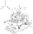
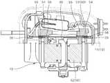
도 1을 참조하면, 압축기(1)는 쉘(10)을 구비한다. 쉘(10)은 그 내부의 공간을 외부의 공간으로부터 격리한다. 쉘(10)의 내부에는 압축하고자 하는 기체가 채워진다. 그리고 쉘(10)의 내부에는 상기 기체를 압축하기 위한 압축작동 조립체(40)가 설치된다.Referring to FIG. 1 , the
상기 압축작동 조립체(40)는 프레임(50)에 구동원, 피스톤, 실린더 등이 설치된 구조일 수 있다. 상기 압축작동 조립체(40)에는 직선왕복 운동하는 피스톤에 의해 진동이 발생한다. 이러한 진동이 쉘(10)에 전달되면, 매우 큰 소음이 발생한다. 이에 압축작동 조립체(40)와 쉘(10) 사이에는 댐퍼가 설치된다. 상기 댐퍼는 압축코일 스프링, 판 스프링과 같은 탄성체를 포함할 수 있다. 상기 압축작동 조립체(40)는 댐퍼 위에 올려져 있는 구조로 쉘(10) 내부에 설치된다. 즉 왕복동 압축기는 압축작동 조립체(40)의 질량(M)과 댐퍼의 스프링 강성(K)으로 구성되는 진동 시스템이다.The
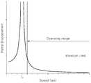
상기 진동 시스템은, 질량(M)과 스프링 강성(K)에 의해 정의되는 고유진동수를 가진다. 따라서 압축작동 조립체(40)에 발생하는 진동이 상기 고유진동수와 일치하면, 소음이 매우 커지고 진동이 증폭된다. 이에, 압축기(1)의 운전속도 영역은, 상기 댐퍼의 고유진동수를 벗어나는 범위에서 설정된다.The vibration system has a natural frequency defined by a mass (M) and a spring stiffness (K). Therefore, when the vibration generated in the
상기 M-K 시스템의 고유진동수는 압축기의 저속 운전영역과 중첩된다. 상기 M-K 시스템에 의해 정의되는 고유진동수를 낮추게 되면, 그만큼 압축기(1)의 운전속도 영역이 늘어날 수 있다. 이처럼 운전속도 영역이 늘어나면, 압축기를 더 효율적으로 운전할 수 있어 압축기의 효율을 높일 수 있다.The natural frequency of the M-K system overlaps with the low-speed operation region of the compressor. If the natural frequency defined by the M-K system is lowered, the operating speed range of the
그러나, M-K 시스템에서 고유진동수를 낮추는 데에는 한계가 있기 때문에, 압축기를 저속으로 운전하는 데에는 제한이 발생할 수밖에 없다. 이러한 사실은 압축기의 효율을 높이는 데에 제약이 된다.However, since there is a limit to lowering the natural frequency in the M-K system, there is inevitably a limitation in operating the compressor at a low speed. This fact is a limitation in increasing the efficiency of the compressor.
아울러 스프링은 탄성이 주로 작용하는 방향이 존재한다. 따라서 중력방향으로 탄성을 충분히 발휘하도록 스프링을 설치하는 경우, 스프링의 탄성은 수평방향으로는 잘 발휘되지 못한다.In addition, the spring has a direction in which elasticity mainly acts. Therefore, when the spring is installed to sufficiently exhibit elasticity in the direction of gravity, the elasticity of the spring is not well exhibited in the horizontal direction.
이에 중력방향과 수평방향으로 모두 탄성이 작용하도록 스프링을 복수 개 설치하거나, 스프링의 탄성 방향이 수평방향과 중력방향을 모두 설치하고자 하면, 부품의 개수가 증가하거나, 스프링의 설치와 조립이 어려워진다는 문제가 있다.Accordingly, if a plurality of springs are installed so that elasticity acts in both the gravity direction and the horizontal direction, or if the elastic direction of the spring is installed in both the horizontal direction and the gravity direction, the number of parts increases or the installation and assembly of the spring becomes difficult. there is a problem.
본 발명은 상술한 문제점을 해결하기 위해 안출된 것으로, 낮은 고유진동수를 가지는 M-K 진동시스템을 탈피함으로써, 압축기의 운전속도 영역을 확장할 수 있는 진동 저감 구조 및 이를 적용한 압축기를 제공하는 것을 목적으로 한다.The present invention has been devised to solve the above problems, and it is an object of the present invention to provide a vibration reduction structure capable of expanding the operating speed range of the compressor by breaking away from the MK vibration system having a low natural frequency, and a compressor to which the same is applied. .
본 발명은, 중력방향과 수평방향으로 모두 댐핑 능력이 뛰어난 진동 저감 구조 및 이를 적용한 압축기를 제공하는 것을 목적으로 한다.An object of the present invention is to provide a vibration reduction structure having excellent damping ability in both the gravitational direction and the horizontal direction, and a compressor to which the same is applied.
본 발명은, 조립이 편리하고 제조 비용을 저감할 수 있는 진동 저감 구조 및 이를 적용한 압축기를 제공하는 것을 목적으로 한다.An object of the present invention is to provide a vibration reduction structure that is convenient to assemble and can reduce manufacturing cost, and a compressor to which the same is applied.
상술한 과제를 해결하기 위해 본 발명은, 현(string)에 압축작동 조립체를 매다는 형태로 압축작동 조립체를 설치함으로써, 현의 인장력을 이용하여 진동을 저감하는 구조 및 이를 적용한 압축기를 제공한다.In order to solve the above problems, the present invention provides a structure for reducing vibration by using the tension of the string by installing the compression operation assembly in the form of suspending the compression operation assembly on a string, and a compressor to which the same is applied.
상기 현은, 길이 방향으로, 압축력에는 저항하지 않고 인장력에는 저항할 수 있다. 상기 현은, 와이어, 로프, 케이블 등일 수 있다.The string may, in the longitudinal direction, resist tensile forces and not compressive forces. The string may be a wire, a rope, a cable, or the like.
상기 압축기는 쉘과 압축작동 조립체를 포함할 수 있다.The compressor may include a shell and a compression actuation assembly.
쉘은 압축기의 내부의 공간과 외부의 공간을 구획할 수 있다.The shell may partition an inner space and an outer space of the compressor.
압축작동 조립체는 상기 쉘의 내부의 공간에 설치될 수 있다.A compression actuation assembly may be installed in the interior space of the shell.
상기 압축작동 조립체는 기체를 압축하는 작동을 하며 진동을 유발할 수 있다.The compression actuating assembly operates to compress the gas and may cause vibration.
상기 압축작동 조립체는 프레임, 상기 프레임에 마련되고 보어를 구비하는 실린더, 및 상기 실린더의 보어에 삽입되어 직선 왕복 운동함으로써 기체를 압축하는 피스톤을 구비할 수 있다.The compression operation assembly may include a frame, a cylinder provided in the frame and having a bore, and a piston inserted into the bore of the cylinder to compress gas by linear reciprocating motion.
상기 쉘과 압축작동 조립체는 현으로 연결될 수 있다.The shell and compression actuation assembly may be connected by strings.
상기 압축작동 조립체는, 상기 현이 연결되는 조립체측 현 연결부를 구비할 수 있다.The compression operation assembly may include an assembly-side string connecting portion to which the string is connected.
상기 쉘은, 상기 현이 연결되는 쉘측 현 연결부를 구비할 수 있다.The shell may include a shell-side string connecting portion to which the string is connected.
상기 압축작동 조립체의 자중에 의해, 상기 현에 인장력이 발생할 수 있다.Due to the weight of the compression actuating assembly, a tensile force may be generated in the string.
상기 압축작동 조립체는 상기 현을 통해 쉘에 매달릴 수 있다.The compression actuation assembly may be suspended from the shell via the string.
상기 압축작동 조립체의 프레임은 쉘과 직접적으로 접하지 않을 수 있다.The frame of the compression actuation assembly may not be in direct contact with the shell.
상기 조립체측 현 연결부는 상기 프레임에 마련될 수 있다.The assembly-side chord connection portion may be provided on the frame.
상기 조립체측 현 연결부는 관통홀을 구비하고, 상기 현은 상기 관통홀을 관통하고, 상기 현의 일측 단부과 타측 단부는 각각 쉘측 현 연결부에 연결될 수 있다.The assembly-side string connecting portion may have a through hole, the string passing through the through hole, and one end and the other end of the string may be connected to the shell-side string connecting portion, respectively.
상기 관통홀은 프레임에 마련될 수 있다.The through hole may be provided in the frame.
상기 쉘측 현 연결부는, 제1 쉘측 현 연결부 및 상기 제1 쉘측 현 연결부와 이격된 위치에 배치된 제2 쉘측 현 연결부를 포함할 수 있다.The shell-side string connection portion may include a first shell-side string connection portion and a second shell-side string connection portion disposed at a position spaced apart from the first shell-side string connection portion.
상기 현의 일측 단부는 상기 제1 쉘측 현 연결부에 연결되고, 상기 현의 타측 단부는 상기 제2쉘측 현 연결부에 연결될 수 있다.One end of the string may be connected to the first shell-side string connection portion, and the other end of the string may be connected to the second shell-side string connection portion.
상기 조립체측 현 연결부는 서로 이격된 위치에 배치된 제1 조립체측 현 연결부와 제2 조립체측 현 연결부를 포함할 수 있다.The assembly-side chord connection portion may include a first assembly-side chord connection portion and a second assembly-side chord connection portion disposed at positions spaced apart from each other.
상기 제1 조립체측 현 연결부와 상기 제2 조립체측 현 연결부는 각각 관통홀을 구비할 수 있다.The first assembly-side string connection portion and the second assembly-side string connection portion may each have a through hole.
상기 제1 조립체측 현 연결부의 관통홀의 관통 방향과 상기 제2 조립체측 현 연결부의 관통홀의 관통 방향은 실질적으로 하나의 직선 선상에 배치될 수 있다.A penetrating direction of the through-hole of the first assembly-side chord connecting portion and a penetrating direction of the through-hole of the second assembly-side chord connecting portion may be substantially arranged on a single straight line.
상기 현은 상기 제1 조립체측 현 연결부의 관통홀과 상기 제2 조립체측 현 연결부의 관통홀을 모두 관통할 수 있다.The string may pass through both the through-hole of the first assembly-side string connection part and the through-hole of the second assembly-side string connection part.
상기 제1 조립체측 현 연결부는 제1방향으로 관통된 제1관통홀을 구비하고, 상기 제2 조립체측 현 연결부는 제2방향으로 관통된 제2관통홀을 구비하고, 상기 제1 조립체측 현 연결부는 제3방향으로 관통된 제3관통홀을 더 구비하고, 상기 제2 조립체측 현 연결부는 제4방향으로 관통된 제4관통홀을 더 구비할 수 있다.The first assembly-side string connection portion has a first through-hole penetrating in a first direction, and the second assembly-side string connection portion has a second through-hole penetrated in the second direction, and the first assembly-side string The connecting portion may further include a third through-hole penetrating in the third direction, and the second assembly-side chord connecting portion may further include a fourth through-hole penetrating in the fourth direction.
상기 제1방향과 제2방향은 실질적으로 하나의 직선 상에 배치될 수 있다.The first direction and the second direction may be substantially arranged on a single straight line.
상기 현은 상기 제1관통홀과 상기 제2관통홀을 관통하는 제1현과, 상기 제3관통홀을 관통하는 제2현과, 상기 제4관통홀을 관통하는 제3현을 포함할 수 있다.The string may include a first string passing through the first through hole and the second through hole, a second string passing through the third through hole, and a third string passing through the fourth through hole.
상기 제1현의 일측 단부는 제1 쉘측 현 연결부에 연결되고, 상기 제1현의 타측 단부는 제1 쉘측 현 연결부와 이격된 위치에 배치된 제2 쉘측 현 연결부에 연결될 수 있다.One end of the first string may be connected to a first shell-side string connection portion, and the other end of the first string may be connected to a second shell-side string connection portion disposed at a position spaced apart from the first shell-side string connection portion.
현의 연결 위치에 대한 하나의 실시예로서, 상기 제2현의 일측 단부는 상기 제1 쉘측 현 연결부와제1거리만큼 이웃하는 제3 쉘측 현 연결부에 연결되고, 상기 제3현의 일측 단부는 상기 제2 쉘측 현 연결부와제2거리만큼 이웃하는 제4 쉘측 현 연결부에 연결되고, 상기 제3 쉘측 현 연결부와 상기 제4 쉘측 현 연결부는제3거리만큼 서로 이격된 위치에 배치될 수 있다. 여기서 제1거리와 제2거리는, 제3거리보다 가까운 거리일 수 있다.As an embodiment of the connection position of the strings, one end of the second string is connected to a third shell-side string connection portion adjacent to thefirst shell-side string connection portion by a first distance, and one end of the third string is The second shell-side chord connecting portion andthe fourth shell-side chord connecting portion adjacent by a second distance may be connected, and the third shell-side chord connecting portion and the fourth shell-side chord connecting portion may be disposed at positions spaced apart from each otherby a third distance. Here, the first distance and the second distance may be closer than the third distance.
상기 제1 내지 제4 쉘측 현 연결부와 모두 이격된 위치에는 제5 쉘측 현 연결부가 배치될 수 있다. 상기 제2현의 타측 단부는 제5 쉘측 현 연결부에 연결될 수 있다. 상기 제5쉘측 현 연결부와 상기 제1 내지 제4 쉘측 현 연결부 사이의 거리들은, 상기 제1거리 및 제2거리보다 먼 거리일 수 있다.A fifth shell-side string connection part may be disposed at positions spaced apart from the first to fourth shell-side string connection parts. The other end of the second string may be connected to the fifth shell-side string connecting portion. Distances between the fifth shell-side string connection part and the first to fourth shell-side string connection parts may be greater than the first distance and the second distance.
상기 제1 내지 제4 쉘측 현 연결부와 모두 이격된 위치에는 제6 쉘측 현 연결부가 배치될 수 있다. 상기 제3현의 타측 단부는 제6 쉘측 현 연결부에 연결될 수 있다. 상기 제6쉘측 현 연결부와 상기 제1 내지 제4 쉘측 현 연결부 사이의 거리들은, 상기 제1거리 및 제2거리보다 먼 거리일 수 있다.A sixth shell-side string connection part may be disposed at positions spaced apart from the first to fourth shell-side string connection parts. The other end of the third string may be connected to the sixth shell-side string connection part. Distances between the sixth shell-side string connection part and the first to fourth shell-side string connection parts may be greater than the first distance and the second distance.
상기 제5 쉘측 현 연결부와 상기 제6 쉘측 현 연결부 사이의 거리는, 상기 제1거리 및 제2거리보다 먼 거리일 수 있다.The distance between the fifth shell-side string connection part and the sixth shell-side string connection part may be greater than the first distance and the second distance.
이에 따르면, 현이 이루는 실질적인 도형은 4각형 이상일 수 있다.Accordingly, the actual figure formed by the string may be a quadrilateral or more.
상기 제5 쉘측 현 연결부와 상기 제6 쉘측 현 연결부 사이의 거리는, 상기 제3거리와 비슷하거나 실질적으로 동일할 수 있다.A distance between the fifth shell-side chord connection part and the sixth shell-side chord connection part may be similar to or substantially the same as the third distance.
이에 따르면, 현이 이루는 실질적인 도형은 4각형일 수 있다.Accordingly, the actual figure formed by the string may be a quadrilateral.
이와 달리, 상기 제5 쉘측 현 연결부와 상기 제6 쉘측 현 연결부 사이의 거리는, 상기 제1거리 및 제2거리와 비슷하거나 실질적으로 동일할 수 있다.Alternatively, the distance between the fifth shell-side chord connection portion and the sixth shell-side chord connection portion may be similar to or substantially equal to the first distance and the second distance.
이에 따르면, 현이 이루는 실질적인 도형은 3각형일 수 있다.Accordingly, the actual figure formed by the string may be a triangle.
현의 연결 위치에 대한 다른 하나의 실시예로서, 상기 제2현의 일측 단부는 상기 제1 쉘측 현 연결부에 연결되고, 상기 제3현의 일측 단부는 상기 제2 쉘측 현 연결부에 연결될 수 있다.As another embodiment of the connection position of the string, one end of the second string may be connected to the first shell-side string connection portion, and one end of the third string may be connected to the second shell-side string connection portion.
상기 제2현의 타측 단부는 상기 제1 및 제2 쉘측 현 연결부와 모두 이격된 위치에 배치된 제3쉘측 현 연결부에 연결될 수 있다.The other end of the second string may be connected to a third shell-side string connecting portion disposed at a position spaced apart from both the first and second shell-side string connecting portions.
상기 제3현의 타측 단부는 상기 제1 내지 제3 쉘측 현 연결부와 모두 이격된 위치에 배치된 제4쉘측 현 연결부에 연결될 수 있다.The other end of the third string may be connected to a fourth shell-side string connecting portion disposed at a position spaced apart from all of the first to third shell-side string connecting portions.
이에 따르면, 현이 이루는 실질적인 도형은 4각형 이상일 수 있다.Accordingly, the actual figure formed by the string may be a quadrilateral or more.
상기 제1 쉘측 현 연결부와 상기 제2 쉘측 현 연결부 사이의 거리는, 상기 제3 쉘측 현 연결부와 상기 제4쉘측 현 연결부 사이의 거리와 비슷하거나 실질적으로 동일할 수 있다.A distance between the first shell-side chord connection part and the second shell-side chord connection part may be similar to or substantially the same as a distance between the third shell-side chord connection part and the fourth shell-side chord connection part.
이에 따르면, 현이 이루는 실질적인 도형은 4각형일 수 있다.Accordingly, the actual figure formed by the string may be a quadrilateral.
이와 달리 상기 제3현의 타측 단부는 상기 제3 쉘측 현 연결부에 연결될 수 있다.Alternatively, the other end of the third string may be connected to the third shell-side string connection part.
이에 따르면, 현이 이루는 실질적인 도형은 3각형일 수 있다.Accordingly, the actual figure formed by the string may be a triangle.
한편, 상기 관통홀의 내주에는 상기 현과 접하되 상기 현과의 마찰계수가 적어 상기 현의 마모를 최소화하는 표면이 구비될 수 있다.On the other hand, the inner periphery of the through hole may be provided with a surface in contact with the string to minimize abrasion of the string with a small friction coefficient with the string.
가령, 상기 관통홀의 내주에는 상기 현과 접하는 부싱이 마련될 수 있다.For example, a bushing in contact with the string may be provided on an inner periphery of the through hole.
상기 쉘측 현 연결부는, 일 예로서, 상기 쉘에 연결되는 연결부재; 상기 연결부재에 형성된 끼움홀; 및 상기 끼움홀에 끼워지는 핀부와, 상기 핀부의 단부에 구비되는 헤드부를 구비하는 고정핀;을 포함할 수 있다.The shell-side string connection portion may include, for example, a connection member connected to the shell; a fitting hole formed in the connecting member; and a fixing pin having a pin portion fitted into the fitting hole and a head portion provided at an end of the pin portion.
상기 현은 상기 헤드부와 연결부재 사이에서 상기 핀부에 걸려 상기 쉘측 현 연결부에 연결될 수 있다.The string may be connected to the shell-side string connecting portion by being caught by the pin portion between the head portion and the connecting member.
다른 일 예로서, 상기 쉘측 현 연결부는, 서로 소정의 간격을 가지고 배치되고, 상기 쉘에 연결되는 제1연결부재과 제2연결부재; 상기 제1연결부재와 제2연결부재에 각각에 형성된 제1끼움홀과 제2끼움홀; 및 상기 제1끼움홀 및 제2끼움홀에 끼워지는 핀부와, 상기 핀부의 단부에 구비되는 헤드부를 구비하는 고정핀;을 포함할 수 있다.As another example, the shell-side chord connecting portion may include: a first connecting member and a second connecting member disposed at a predetermined distance from each other and connected to the shell; a first fitting hole and a second fitting hole respectively formed in the first connecting member and the second connecting member; and a fixing pin having a pin portion fitted into the first fitting hole and the second fitting hole, and a head portion provided at an end of the pin portion.
상기 현은 상기 제1연결부재와 제2연결부재 사이에서 상기 핀부에 걸려 상기 쉘측 현 연결부에 연결될 수 있다.The string may be connected to the shell-side string connecting portion by being caught by the pin portion between the first connecting member and the second connecting member.
다른 일 예로서, 상기 쉘측 현 연결부는, 상기 쉘에 연결되는 연결부재; 상기 연결부재로부터 돌출된 보스; 및 상기 보스에 끼워지는 링부재;를 포함할 수 있다.As another example, the shell-side string connecting portion may include a connecting member connected to the shell; a boss protruding from the connecting member; and a ring member fitted to the boss.
상기 현은 상기 연결부재와 링부재 사이에서 상기 보스에 걸려 상기 쉘측 현 연결부에 연결될 수 있다.The string may be caught by the boss between the connecting member and the ring member and connected to the shell-side string connecting portion.
다른 일 예로서, 상기 쉘측 현 연결부는, 상기 쉘에 연결되는 연결부재; 상기 연결부재로부터 돌출된 보스; 및 상기 보스의 단부에 마련된 보스헤드;를 포함할 수 있다.As another example, the shell-side string connecting portion may include a connecting member connected to the shell; a boss protruding from the connecting member; and a boss head provided at an end of the boss.
상기 현은 상기 연결부재와 보스헤드 사이에서 상기 보스에 걸려 상기 쉘측 현 연결부에 연결될 수 있다.The string may be caught by the boss between the connecting member and the boss head and connected to the shell-side string connecting portion.
상기 진동 저감 구조가 적용된 압축기의 쉘은, 적어도 압축기의 하부를 규정하는 하부쉘과, 적어도 압축기의 상부를 규정하고 상기 하부쉘과 결합하는 상부쉘을 포함할 수 있다.The shell of the compressor to which the vibration reduction structure is applied may include a lower shell defining at least a lower portion of the compressor, and an upper shell defining at least an upper portion of the compressor and coupled to the lower shell.
상기 쉘측 현 연결부는 상기 하부쉘에 연결될 수 있다.The shell-side chord connection portion may be connected to the lower shell.
이와 달리 상기 쉘측 현 연결부는 상기 상부쉘에 연결될 수 있다.Alternatively, the shell-side chord connection portion may be connected to the upper shell.
본 발명의 압축기의 진동 저감 구조에 따르면, 현의 인장력을 이용하여 압축작동 조립체를 쉘에 연결하므로, 종래의 M-K 시스템과 달리 고유진동수가 존재하지 않아 압축기의 운전속도 영역을 더욱 확장할 수 있다.According to the vibration reduction structure of the compressor of the present invention, since the compression operation assembly is connected to the shell using the tension force of the strings, unlike the conventional M-K system, there is no natural frequency, so the operation speed range of the compressor can be further expanded.
본 발명에 따르면 현의 인장력이 중력방향은 물론 수평방향으로도 뛰어난 댐핑력을 제공할 수 있다.According to the present invention, the tensile force of the string can provide excellent damping force not only in the gravitational direction but also in the horizontal direction.
따라서 부품 수를 줄일 수 있고 조립이 간단해지며, 이에 따라 제조 비용을 절감할 수 있다.Accordingly, the number of parts can be reduced and assembly is simplified, thereby reducing manufacturing costs.
상술한 효과와 더불어 본 발명의 구체적인 효과는 이하 발명을 실시하기 위한 구체적인 사항을 설명하면서 함께 기술한다.In addition to the above-described effects, the specific effects of the present invention will be described together while describing specific details for carrying out the invention below.
도 1은 왕복동식 압축기의 측면 단면도이다.
도 2는 스프링을 이용한 댐퍼가 적용된 압축작동 조립체에 작용하는 6자유도 진동을 나타낸 도면이다.
도 3은 스프링을 이용한 댐퍼를 적용한 압축기의 고유진동수와 운전 범위를 나타낸 그래프이다.
도 4는 본 발명에 진동 저감 구조가 적용된 압축기의 제1실시예의 측면 단면도이다.
도 5는 도 4의 압축기의 평면도이다.
도 6은 도 5의 압축기에서 상부프레임을 생략한 상태를 나타낸 도면이다.
도 7은, 도 3의 그래프에 더하여, 본 발명에 따른 진동 저감 구조가 적용된 압축기의 고유진동수와 운전 범위를 함께 나타낸 그래프이다.
도 8은 도 3의 고유진동수와 도 7의 고유진동수를 비교한 그래프이다.
도 9는 본 발명에 진동 저감 구조가 적용된 압축기의 제2실시예의 측면 단면도이다.
도 10은 도 9의 압축기의 평면도이다.
도 11은 도 10의 압축기에서 상부프레임을 생략한 상태를 나타낸 도면이다.
도 12는 본 발명에 따른 진동 저감 구조가 적용된 압축기의 제3실시예의 측면 단면도이다.
도 13은 도 12의 압축기의 평면도이다.
도 14는 도 13의 압축기에서 상부프레임을 생략한 상태를 나타낸 도면이다.
도 15 내지 도 18은 현과 쉘측 현 연결부의 연결 방식의 제1실시예 내지 제4실시예를 각각 나타낸 도면이다.1 is a side cross-sectional view of a reciprocating compressor;
FIG. 2 is a view showing six degrees of freedom vibration acting on a compression operation assembly to which a damper using a spring is applied.
3 is a graph showing the natural frequency and operating range of a compressor to which a damper using a spring is applied.
4 is a side cross-sectional view of the first embodiment of the compressor to which the vibration reduction structure is applied to the present invention.
FIG. 5 is a plan view of the compressor of FIG. 4 .
6 is a view showing a state in which the upper frame is omitted from the compressor of FIG. 5 .
7 is a graph showing the natural frequency and operating range of the compressor to which the vibration reduction structure according to the present invention is applied, in addition to the graph of FIG. 3 .
8 is a graph comparing the natural frequency of FIG. 3 and the natural frequency of FIG. 7 .
9 is a side cross-sectional view of a second embodiment of the compressor to which the vibration reduction structure of the present invention is applied.
10 is a plan view of the compressor of FIG. 9 .
11 is a view showing a state in which the upper frame is omitted from the compressor of FIG. 10 .
12 is a side cross-sectional view of a third embodiment of a compressor to which a vibration reduction structure according to the present invention is applied.
13 is a plan view of the compressor of FIG. 12 .
14 is a view showing a state in which the upper frame is omitted from the compressor of FIG. 13 .
15 to 18 are views showing the first to fourth embodiments of the connection method of the string and the shell side string connection part, respectively.
전술한 목적, 특징 및 장점은 첨부된 도면을 참조하여 상세하게 후술되며, 이에 따라 본 발명이 속하는 기술분야에서 통상의 지식을 가진 자가 본 발명의 기술적 사상을 용이하게 실시할 수 있을 것이다. 본 발명을 설명함에 있어서 본 발명과 관련된 공지 기술에 대한 구체적인 설명이 본 발명의 요지를 불필요하게 흐릴 수 있다고 판단되는 경우에는 상세한 설명을 생략한다. 이하, 첨부된 도면을 참조하여 본 발명에 따른 바람직한 실시예를 상세히 설명하기로 한다. 도면에서 동일한 참조부호는 동일 또는 유사한 구성요소를 가리키는 것으로 사용된다.The above-described objects, features and advantages will be described below in detail with reference to the accompanying drawings, and accordingly, those of ordinary skill in the art to which the present invention pertains will be able to easily implement the technical idea of the present invention. In describing the present invention, if it is determined that a detailed description of a known technology related to the present invention may unnecessarily obscure the gist of the present invention, the detailed description will be omitted. Hereinafter, preferred embodiments according to the present invention will be described in detail with reference to the accompanying drawings. In the drawings, the same reference numerals are used to indicate the same or similar components.
이하 실시예를 설명함에 있어서 축방향이라 함은 피스톤의 직선 왕복 운동 방향을 의미한다. 전방이라 함은 축방향으로 피스톤이 실린더에 들어가는 방향과 나란한 방향을 의미한다. 후방이라 함은 축방향으로 피스톤이 실린더로부터 나오는 방향과 나란한 방향을 의미한다. 반경방향이라 함은 상기 축으로부터 멀어지거나 축에 가까워지는 방향을 의미한다. 원심방향이라 함은 상기 축으로부터 멀어지는 방향을 의미하고, 구심방향이라 함은 상기 축에 가까워지는 방향을 의미한다. 원주방향 또는 둘레방향이라 함은 상기 축의 둘레를 감싸는 방향을 의미한다.In the following description of the embodiment, the axial direction means a linear reciprocating motion direction of the piston. Forward means the direction parallel to the direction in which the piston enters the cylinder in the axial direction. By rearward is meant the direction parallel to the direction in which the piston exits the cylinder in the axial direction. The radial direction means a direction away from or close to the axis. The centrifugal direction means a direction away from the axis, and the centripetal direction means a direction approaching the axis. The circumferential direction or the circumferential direction means a direction surrounding the circumference of the shaft.
또한 상하 방향이라 함은 중력이 작용하는 방향을 가리킨다. 상방은 중력의 방향의 반대방향을 의미할 수 있다. 좌우 방향 또는 측 방향은, 상기 축방향 및 상하 방향에 모두 수직한 방향을 의미할 수 있다.In addition, the vertical direction refers to the direction in which gravity acts. Upward may mean a direction opposite to the direction of gravity. The left-right direction or the lateral direction may mean a direction perpendicular to both the axial direction and the vertical direction.
비록 제1, 제2 등이 다양한 구성요소들을 서술하기 위해서 사용되나, 이들 구성요소들은 이들 용어에 의해 제한되지 않음은 물론이다. 이들 용어들은 단지 하나의 구성요소를 다른 구성요소와 구별하기 위하여 사용하는 것으로, 특별히 반대되는 기재가 없는 한, 제1 구성요소는 제2 구성요소일 수도 있음은 물론이다.Although the first, second, etc. are used to describe various elements, these elements are not limited by these terms, of course. These terms are only used to distinguish one component from other components, and unless otherwise stated, the first component may be the second component, of course.
명세서 전체에서, 특별히 반대되는 기재가 없는 한, 각 구성요소는 단수일 수도 있고 복수일 수도 있다.Throughout the specification, unless otherwise stated, each element may be singular or plural.
떤 구성요소가 다른 구성요소에 "연결", "결합" 또는 "접속"된다고 기재된 경우, 상기 구성요소들은 서로 직접적으로 연결되거나 또는 접속될 수 있지만, 각 구성요소 사이에 다른 구성요소가 "개재"되거나, 각 구성요소가 다른 구성요소를 통해 "연결", "결합" 또는 "접속"될 수도 있는 것으로 이해되어야 할 것이다.When it is described that a component is “connected”, “coupled” or “connected” to another component, the components may be directly connected or connected to each other, but the other component is “interposed” between each component. Alternatively, it will be understood that each component may be “connected”, “coupled” or “connected” through another component.
본 명세서에서 사용되는 단수의 표현은 문맥상 명백하게 다르게 뜻하지 않는 한, 복수의 표현을 포함한다. 본 출원에서, "구성된다" 또는 "포함한다" 등의 용어는 명세서 상에 기재된 여러 구성 요소들, 또는 여러 단계들을 반드시 모두 포함하는 것으로 해석되지 않아야 하며, 그 중 일부 구성 요소들 또는 일부 단계들은 포함되지 않을 수도 있고, 또는 추가적인 구성 요소 또는 단계들을 더 포함할 수 있는 것으로 해석되어야 한다.As used herein, the singular expression includes the plural expression unless the context clearly dictates otherwise. In the present application, terms such as "consisting of" or "comprising" should not be construed as necessarily including all of the various components or various steps described in the specification, some of which components or some steps are It should be construed that it may not include, or may further include additional components or steps.
또한, 본 명세서에서 사용되는 단수의 표현은 문맥상 명백하게 다르게 뜻하지 않는 한, 복수의 표현을 포함한다. 본 출원에서, "구성된다" 또는 "포함한다" 등의 용어는 명세서 상에 기재된 여러 구성 요소들, 또는 여러 단계들을 반드시 모두 포함하는 것으로 해석되지 않아야 하며, 그 중 일부 구성 요소들 또는 일부 단계들은 포함되지 않을 수도 있고, 또는 추가적인 구성 요소 또는 단계들을 더 포함할 수 있는 것으로 해석되어야 한다.Also, as used herein, the singular expression includes the plural expression unless the context clearly dictates otherwise. In the present application, terms such as "consisting of" or "comprising" should not be construed as necessarily including all of the various components or various steps described in the specification, some of which components or some steps are It should be construed that it may not include, or may further include additional components or steps.
명세서 전체에서, "A 및/또는 B" 라고 할 때, 이는 특별한 반대되는 기재가 없는 한, A, B 또는 A 및 B 를 의미하며, "C 내지 D" 라고 할 때, 이는 특별한 반대되는 기재가 없는 한, C 이상이고 D 이하인 것을 의미한다Throughout the specification, when “A and/or B” is used, it means A, B or A and B, unless specifically stated to the contrary, and when “C to D” is used, it means that there is no specific contrary description. Unless otherwise specified, it means that it is greater than or equal to C and less than or equal to D.
[압축기 구조] [Compressor Structure]
도 1 내지 도 3을 참조하여, 스프링 댐퍼가 적용된 압축기의 구조를 설명한다. 본 발명에서 예시하는 압축기(1)는 왕복동식 압축기이다. 그러나 이 외에도, 실시예의 진동 저감 구조는, 직선 왕복 운동하는 피스톤을 구비하는 리니어 압축기에 적용될 수 있다. 또한 실시예의 진동 저감 구조는 진동이 발생하는 압축기에 모두 적용될 수 있다.A structure of a compressor to which a spring damper is applied will be described with reference to FIGS. 1 to 3 . The
압축기(1)의 압축작동 조립체(40)는 쉘(10) 내부에 설치된다.The
쉘(10)은 깊은 용기 형태의 상부쉘(11)과, 상기 상부쉘(11)의 상부를 덮어 밀봉하는 하부쉘(12)을 포함한다. 상부쉘(11)의 저부에는 레그(13)가 마련되어 있다. 상기 레그(13)는 상기 압축기(1)를 설치하고자 하는 위치에 상기 압축기(1)를 고정하기 위한 구성이다.The
압축작동 조립체(40)는 프레임(50)과, 구동원(60)과, 실린더(72)와, 피스톤(71)을 포함한다.The
프레임(50)은 하부프레임(53)과 상부프레임(51)으로 이루어질 수 있다.The
구동원(60)은 전동 모터일 수 있다. 상기 전동 모터는 회전 모터일 수 있고, 상기 회전 모터는 스테이터 및 상기 스테이터에 의해 상대적으로 회전하는 로터를 포함할 수 있다. 상기 전동 모터는 리니어 모터일 수 있고, 상기 리니어 모터는 스테이터 및 상기 스테이터에 대해 상대적으로 직선왕복 운동하는 무버를 포함할 수 있다. 회전 모터는 실시예와 같은 왕복동식 압축기에 적용될 수 있고, 리니어 모터는 리니어 압축기에 적용될 수 있다.The driving
실시예의 회전 모터(61)의 스테이터(66)는 상기 하부프레임(53)에 고정될 수 있다.The
회전축(63)은 상기 스테이터(66)와 동심을 이루며, 수직으로 연장된다. 상기 로터(62)는 상기 회전축(63)에 설치되어 상기 회전축(63)과 함께 회전할 수 있다. 회전축(63)의 상단부에는 상기 회전축(63)의 직경을 확장시키는 원반부재(64)가 마련된다. 원반부재(64)의 저면은, 상부프레임(51)에 설치된 베어링(52)에 의해, 회전 방향으로 그리고 스러스트 방향으로 지지된다. 크랭크핀(65)은, 원반부재(64)의 상면에서 상기 회전축(63)의 중심과 편심된 위치로부터, 상방으로 연장된다.The rotating
상부프레임(51)은 하부프레임(53)에 고정된다. 상기 상부프레임(51)은 실린더(72)를 구비한다. 상기 실린더(72)는 전후 방향으로 연장되는 보어(73)를 구비한다. 상기 보어(73)에는 피스톤(71)이 삽입된다. 상기 실린더(72) 내에서, 상기 피스톤(71)의 전방에 마련된 공간은 압축실(74)이 된다. 상기 피스톤(71)은 커넥팅로드(75)를 통해 상기 크랭크핀(65)에 연결된다.The
모터(61)에 전원이 공급되면 상기 회전축(63)이 회전하고, 이에 따라 크랭크핀(65)은 상기 회전축(63)의 둘레를 선회한다. 상기 크랭크핀(65)에 연결된 커넥팅로드(75)는, 실린더(72)에 의해 전후 방향으로만 이동 가능하도록 구속된 피스톤(71)을 직선왕복 운동시킨다.When power is supplied to the
상기 압축작동 조립체(40)에는, 상기 피스톤(71)의 직선왕복 운동의 주기에 대응하는 진동이 발생한다. 이러한 진동이 쉘(10)에 전달되는 것을 방지하기 위해, 상기 압축작동 조립체(40)와 쉘(10) 사이에는 진동 저감 구조가 마련된다.Vibration corresponding to the period of the linear reciprocating motion of the
도 1을 참조하면, 쉘(10)의 내부 공간에서 바닥에는 돌기(121)가 마련된다. 돌기(121)는 압축코일스프링과 같은 스프링(81)의 하부를 고정한다. 상기 스프링(81)의 상부에는 압축작동 조립체(40)의 프레임(50)이 고정된다. 상기 스프링(81)은, 상기 프레임(50)이 상기 쉘(10)에 직접 연결되지 않도록 하면서, 상기 프레임(50)을 상기 쉘(10)에 고정한다. 따라서 스프링(81)에 의해, 상기 프레임(50)의 진동이 상기 쉘(10)으로 전달되는 것이 방지된다.Referring to FIG. 1 , a
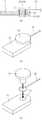
도 2를 참조하면, 상기 압축작동 조립체(40)의 진동 변위는, 6자유도 운동에 의해 나타난다. 그리고 이러한 6자유도 운동은 다음과 같은 운동 방정식으로 표현될 수 있다.Referring to FIG. 2 , the oscillating displacement of the
[M]X"+ [C]X'+ [K]X = F(t)[M]X"+ [C]X'+ [K]X = F(t)
이러한 진동에는, 질량(M)과 강성(K)의 관계에 의해 공진주파수(natural frequency; 고유진동수라고도 함)가 존재하며, 이를 표현하면 다음과 같다.In these vibrations, a resonance frequency (also called natural frequency) exists due to the relationship between the mass (M) and the stiffness (K), and it is expressed as follows.
fn= 1/2π * (K/M)1/2fn = 1/2π * (K/M)1/2
고유진동수가 발생하는 영역의 속도로 피스톤(71)이 직선왕복 운동하게 되면, 진동이 증폭되어 큰 소음이 발생한다. 이에 압축기(1)의 운전 범위(operating range)는 도 3에 도시된 바와 같이 공진주파수에 의해 제한될 수 있다. 상기 공진주파수가 더 낮아지도록 압축기를 설계하면, 압축기(1)의 운전 범위를 저속 영역에서 더 확보하여 압축기(1)의 운전 효율을 향상시킬 수 있다.When the
[진동 저감 구조][Vibration reduction structure]
<제1실시예><First embodiment>
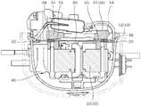
이하 도 4 내지 도 8을 참조하여, 압축기(1)의 운전 범위를 확장하기 위한 진동 저감 구조의 제1실시예를 설명한다. 도 4 내지 도 6에는 상부쉘이 생략된 압축기가 도시되어 있다.Hereinafter, a first embodiment of a vibration reduction structure for extending the operating range of the
상기 진동 저감 구조는, 현(90)을 포함한다. 현(90)은 길이방향으로 연장되는 플렉시블한 부품으로서, 길이방향을 따라 발생하는 인장력에 저항한다. 상기 현(90)은 와이어, 케이블, 로프 등으로도 불릴 수 있다. 상기 현은 가느다란 금속 재질의 와이어를 꼬아서 만든 와이어 다발일 수 있다. 상기 현의 둘레에는 합성수지가 코팅될 수 있다. 상기 합성수지는 플렉시블하면서, 미끄럼 마찰계수가 낮은 재질일 수 있으며, 내마모도가 높은 재질일 수 있다.The vibration reduction structure includes a
압축기(1)의 쉘(10)에는 쉘측 현 연결부(20)가 마련된다. 상기 현(90)은 상기 쉘측 현 연결부(20)에 연결되어 고정될 수 있다. 상기 현(90)의 일측 단부는 상기 쉘측 현 연결부(20)에 직접 고정될 수 있다. 이와 달리, 상기 현(90)은 상기 쉘측 현 연결부(20)에 의해 지지되되 길이방향으로는 고정되지 않은 상태이고, 상기 현(90)의 단부는 쉘(10)의 다른 부위에 고정될 수도 있다. 즉 상기 쉘측 현 연결부(20)는 쉘(10) 측에서 현(90)을 지지하는 지지부일 수 있다.The
실시예에 따르면, 상기 현(90)은 그 양측 단부가 모두 상기 압축기(1)의 쉘(10)에 의해 지지될 수 있다. 그리고 상기 압축작동 조립체(40)는, 상기 현(90)에 매달린 상태로 상기 현(90)에 설치될 수 있다.According to the embodiment, both ends of the
상기 현(90)은 상기 쉘(10)의 상측 부위에서 지지될 수 있다. 제1실시예에 따르면, 상기 쉘측 현 연결부(20)는 하부쉘(12)의 상측 부위에 마련되고, 상기 현(90)은 상기 쉘측 현 연결부(20)에 연결되어 지지될 수 있다.The
상기 압축작동 조립체(40)에는, 상기 현(90)이 연결되는 조립체측 현 연결부(54)를 구비할 수 있다. 상기 조립체측 현 연결부(54)는, 상기 압축작동 조립체(40)의 프레임(50)의 상부프레임(51)에 마련된 관통홀(55)일 수 있다. 상기 현(90)은 상기 관통홀(55)을 관통하여 상기 압축작동 조립체(40)에 연결될 수 있다.The
상기 진동 저감 구조에 따르면, 현(90)의 양측 단부는 쉘(10)에 연결되어 지지되고, 상기 상부프레임(51)은 상기 현(90)에 매달리고, 상기 하부프레임(53)은 상부프레임(51)에 고정된다. 이에 따라 상기 압축작동 조립체(40)는 상기 현(90)에 매달린 형태로 상기 쉘(10)의 내부에 설치될 수 있다.According to the vibration reduction structure, both ends of the
상기 현(90)이 상기 관통홀(55)을 관통하여 설치됨에 따라, 상기 압축작동 조립체(40)는 상기 현(90)의 길이방향에 대해 상기 현(90)에 고정되지 않도록 할 수 있다.As the
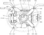
구체적으로, 상기 압축작동 조립체(40)는 제1 조립체측 현 연결부(541), 제2 조립체측 현 연결부(542), 제3 조립체측 현 연결부(543) 및 제4 조립체측 현 연결부(544)를 구비할 수 있다.Specifically, the
제1 조립체측 현 연결부(541)와 제2 조립체측 현 연결부(542)는 전후 방향으로 소정의 간격만큼 이격 배치될 수 있다. 제3 조립체측 현 연결부(543)와 제4 조립체측 현 연결부(544)도 전후 방향으로 소정의 간격만큼 이격 배치될 수 있다.The first assembly-side
제1 조립체측 현 연결부(541)와 제3 조립체측 현 연결부(543)는 측방향, 즉 좌우방향으로 소정의 간격만큼 이격 배치될 수 있다. 제2 조립체측 현 연결부(542)와 제4 조립체측 현 연결부(544) 역시 측방향으로 소정의 간격만큼 이격 배치될 수 있다.The first assembly-side
제1 조립체측 현 연결부(541)와 제4 조립체측 현 연결부(544)는 압축작동 조립체(40)의 중심을 기준으로 대향하는 위치에 배치될 수 있다. 제2 조립체측 현 연결부(542)와 제3 조립체측 현 연결부(543) 역시 압축작동 조립체(40)의 중심을 기준으로 대향하는 위치에 배치될 수 있다.The first assembly-side
상기 제1 내지 제4 조립체측 현 연결부(544)는, 정사각형의 네 코너 위치와 대응하는 위치에 마련될 수 있다. 상기 제1 내지 제4 조립체측 현 연결부(544)의 위치는, 이를 관통하는 현(90)이 상기 압축작동 조립체(40)와 간섭되지 않도록 하는 위치에 선정될 수 있다.The first to fourth assembly-side
상기 제1 내지 제4 조립체측 현 연결부(544)는, 상기 상부프레임(51)에서, 상기 하부프레임(53)과 연결되는 부분 부근에 배치될 수 있다. 상기 제1 내지 제4 조립체측 현 연결부(544)는, 상기 상부프레임(51)의 중심으로부터 방사상으로 외향 연장된 부분에 마련될 수 있다.The first to fourth assembly-side
제1 내지 제4 조립체측 현 연결부(544)에는, 각각 2개씩의 관통홀(55)이 형성될 수 있다.Two through
제1 조립체측 현 연결부(541)에는 제1방향으로 관통된 제1 관통홀(551)이 마련되고, 상기 제2 조립체측 현 연결부(542)에는 제2방향으로 관통된 제2 관통홀(552)이 마련될 수 있다. 상기 제1방향과 상기 제2방향은 동일 직선 상에 배치될 수 있다.A first through-hole 551 penetrating in a first direction is provided in the first assembly-side
또한 제1 조립체측 현 연결부(541)에는 제3방향으로 관통된 제3 관통홀(553)이 마련되고, 상기 제2 조립체측 현 연결부(542)에는 제4방향으로 관통된 제4 관통홀(554)이 마련될 수 있다. 제1방향과 제3방향은 서로 다른 방향일 수 있고, 제2방향과 제4방향은 서로 다른 방향일 수 있다.In addition, a third through-hole 553 penetrating in the third direction is provided in the first assembly-side
제3 조립체측 현 연결부(543)에는 제5방향으로 관통된 제5 관통홀(555)이 마련되고, 상기 제4 조립체측 현 연결부(544)에는 제6방향으로 관통된 제6 관통홀(556)이 마련될 수 있다. 상기 제3방향과 상기 제5방향은 동일 직선 상에 배치될 수 있고, 상기 제4방향과 상기 제6방향은 동일 직선 상에 배치될 수 있다.A fifth through-hole 555 penetrating in a fifth direction is provided in the third assembly-side
또한 제3 조립체측 현 연결부(543)에는 제7방향으로 관통된 제7 관통홀(557)이 마련되고, 상기 제4 조립체측 현 연결부(544)에는 제8방향으로 관통된 제8 관통홀(558)이 마련될 수 있다. 제5방향과 제7방향은 서로 다른 방향일 수 있고, 제6방향과 제8방향은 서로 다른 방향일 수 있다. 상기 제7방향과 상기 제8방향은 동일 직선 상에 배치될 수 있다.In addition, a seventh through-hole 557 penetrating in the seventh direction is provided in the third assembly-side
이처럼 서로 다른 두 조립체측 현 연결부(54)에 각각 배치된 관통홀(55)은 서로 대응하는 관통방향을 가질 수 있다.As such, the through-
상기 관통홀(55)의 내주는 현(90)과 접하며 발생하는 마찰을 최소화할 수 있는 표면을 구비할 수 있다. 이러한 표면은 관통홀(55)에 끼워지는 부싱(56)에 의해 제공될 수 있다. 상기 부싱(56)은 상기 관통홀(55)의 길이방향의 일부 구간에 끼워지거나, 전체 구간에 끼워질 수 있다. 실시예에서는 일부 구간에 부싱(56)이 끼워진 상태가 예시된다.The inner periphery of the through
상기 현(90)은 제1 내지 제4 현(90)을 구비할 수 있다. 제1 현(901)은 상기 제1 관통홀(551)과 제2 관통홀(552)을 모두 관통할 수 있다. 제2 현(902)은 상기 제3 관통홀(553)과 상기 제5 관통홀(555)을 모두 관통할 수 있다. 제3 현(903)은 상기 제4 관통홀(554)과 상기 제6 관통홀(556)을 모두 관통할 수 있다. 제4 현(904)은 상기 제7 관통홀(557)과 상기 제8 관통홀(558)을 모두 관통할 수 있다.The
상기 압축작동 조립체는 하나의 현에 대해 서로 다른 두 위치에서 매달리므로, 압축작동 조립체의 수평을 쉽게 유지할 수 있어 안정적으로 매달린 상태를 유지할 수 있고, 압축작동 조립체의 하중을 하나의 현에 분산해서 전달할 수 있다.Since the compression operation assembly is suspended at two different positions with respect to one string, it is possible to easily maintain the horizontal level of the compression operation assembly to maintain a stable suspended state, and to distribute the load of the compression operation assembly to one string and transmit it can
상기 제1 현(901)의 일측 단부인 전방 단부는 상기 쉘(10)의 전방 우측에 마련된 제1 쉘측 현 연결부(201)에 연결되고, 상기 제1 현(901)의 타측 단부인 후방 단부는 상기 쉘(10)의 후방 우측에 마련된 제2 쉘측 현 연결부(202)에 연결될 수 있다. 이에 따라 상기 압축작동 조립체(40)는 상기 제1 관통홀(551), 제2 관통홀(552) 및 제1 현(901)에 의해 상기 쉘(10)에 매달릴 수 있다.The front end, which is one end of the
상기 제2 현(902)의 일측 단부인 우측 단부는 상기 쉘(10)의 우측 전방에 마련된 제3 쉘측 현 연결부(203)에 연결되고, 상기 제2 현(902)의 타측 단부인 좌측 단부는 상기 쉘(10)의 좌측 전방에 마련된 제5 쉘측 현 연결부(205)에 연결될 수 있다. 이에 따라 상기 압축작동 조립체(40)는 상기 제3 관통홀(553), 제5 관통홀(555) 및 제2 현(902)에 의해 상기 쉘(10)에 매달릴 수 있다.The right end, which is one end of the
상기 제3 현(903)의 일측 단부인 우측 단부는 상기 쉘(10)의 우측 후방에 마련된 제4 쉘측 현 연결부(204)에 연결되고, 상기 제3 현(903)의 타측 단부인 좌측 단부는 상기 쉘(10)의 좌측 후방에 마련된 제6 쉘측 현 연결부(206)에 연결될 수 있다. 이에 따라 상기 압축작동 조립체(40)는 상기 제4 관통홀(554), 제6 관통홀(556) 및 제3 현(903)에 의해 상기 쉘(10)에 매달릴 수 있다.The right end, which is one end of the
상기 제4 현(904)의 일측 단부인 전방 단부는 상기 쉘(10)의 전방 좌측에 마련된 제7 쉘측 현 연결부(207)에 연결되고, 상기 제4 현(904)의 타측 단부인 후방 단부는 상기 쉘(10)의 후방 좌측에 마련된 제8 쉘측 현 연결부(208)에 연결될 수 있다. 이에 따라 상기 압축작동 조립체(40)는 상기 제7 관통홀(557), 제8 관통홀(558) 및 제4 현(904)에 의해 상기 쉘(10)에 매달릴 수 있다.The front end, which is one end of the
상기 제1 쉘측 현 연결부(201)와 상기 제3 쉘측 현 연결부(203)는 서로 가장 가깝게 배치되고, 상기 제1 내지 제4 조립체측 현 연결부들 중 상기 제1 조립체측 현 연결부(541)에 가장 가깝게 배치될 수 있다. 상기 제2 쉘측 현 연결부(202)와 상기 제4 쉘측 현 연결부(204)는 서로 가장 가깝게 배치되고, 상기 제1 내지 제4 조립체측 현 연결부들 중 상기 제2 조립체측 현 연결부(542)에 가장 가깝게 배치될 수 있다. 상기 제5 쉘측 현 연결부(205)와 상기 제7 쉘측 현 연결부(207)는 서로 가장 가깝게 배치되고, 상기 제1 내지 제4 조립체측 현 연결부들 중 상기 제3 조립체측 현 연결부(543)에 가장 가깝게 배치될 수 있다. 상기 제6 쉘측 현 연결부(206)와 상기 제8 쉘측 현 연결부(208)는 서로 가장 가깝게 배치되고, 상기 제1 내지 제4 조립체측 현 연결부들 중 상기 제4 조립체측 현 연결부(544)에 가장 가깝게 배치될 수 있다.The first shell-side
이러한 현 배치 방식에 따르면, 하나의 현의 길이를 충분히 확보할 수 있어 현에 가해지는 인장력을 분산시킬 수 있고, 진동 저감 능력을 향상시킬 수 있다.According to such a string arrangement method, the length of one string can be sufficiently secured, so that the tensile force applied to the string can be dispersed, and the vibration reduction ability can be improved.
제1실시예에 따른 현들의 분포는 정사각형과 대응할 수 있다. 그러나 본 발명의 기술적 사상이 이러한 형상에 한정되는 것은 아니다. 가령 현은 3가닥 구비될 수 있고 현들의 분포는 삼각형과 대응할 수도 있다. 또한 현은 5가닥 이상 구비될 수 있고 현들의 분포는 오각형 이상일 수도 있다.The distribution of chords according to the first embodiment may correspond to a square. However, the technical spirit of the present invention is not limited to this shape. For example, three strings may be provided, and the distribution of strings may correspond to a triangle. In addition, five or more strings may be provided, and the distribution of the strings may be a pentagon or more.
제1실시예에 따르면, 전후 방향으로 발생하는 압축작동 조립체(40)의 진동은 제2 현(902)과 제3 현(903)이 저감할 수 있다. 그리고 좌우 방향으로 발생하는 압축작동 조립체(40)의 진동은 제1 현(901)과 제4 현(904)이 저감할 수 있다. 또한 회전 진동에 대해서는 모든 현이 저감할 수 있다.According to the first embodiment, the vibration of the
제1실시예에 따르면, 서로 다른 위치에서 연장되고 서로 다른 방향으로 연장되는 현들의 양단부는 쉘에 고정된 상태에서 직선 방향으로 곧게 긴장되어 있다. 그리고 상기 압축작동 조립체(40)는, 각각의 현에 대해서는 현의 연장방향으로 간섭되지 않은 상태이지만, 서로 다른 위치에서 연장되고 서로 다른 방향으로 연장되는 현들에 의해 그 위치가 유지된다. 따라서 압축작동 조립체(40)의 자중은 상기 현들에 인장력으로 작용하게 된다.According to the first embodiment, both ends of the strings extending in different positions and extending in different directions are straightened in a straight line while being fixed to the shell. And the
또한, 상기 압축작동 조립체(40)는, 현들에 매달린 상태에서, 기체가 유동하는 배관을 통해 쉘(10)에 간접적으로 연결되는 부위를 제외하고는, 쉘(10)과 직접 접촉하지 않는다. 따라서 상기 압축작동 조립체(40)의 진동은 현(90)에 의해 저감되므로, 쉘(10)에 직접적으로 전달되지 않는다. 아울러, 서로 다른 위치에서 연장되고 서로 다른 방향으로 연장되는 현들이 상기 압축작동 조립체(40)의 자세를 유지해주므로, 압축작동 조립체(40)에 진동이 발생하더라도 압축작동 조립체(40)가 크게 흔들리는 일이 없다.In addition, the
한편, 쉘측 현 연결부(20)와 쉘(10)의 연결 부위는, 해당 쉘측 현 연결부(20)에 연결된 현(90)이 길이방향으로 연장된 선 상에 위치할 수 있다. 가령, 도 6을 참조하면, 제1 현(901)의 양단부를 지지하는 제1 쉘측 현 연결부(201) 및 제2 쉘측 현 연결부(202)와 쉘(10)의 연결부위들은, 상기 제1 현(901)이 길이방향으로 연장된 선(L) 상에 배치될 수 있다. 이러한 구조에 따르면, 현(90)의 인장력이 쉘측 현 연결부(20)와 쉘(10)의 연결부위에 골고루 작용하므로, 연결부위의 어느 한 쪽 코너에 응력이 집중되어 파손되는 현상을 방지할 수 있다.On the other hand, the connecting portion of the shell-side
도 7과 도 8을 참조하면, ①과 같이 스프링(81)에 의해 댐핑 지지되는 경우와 달리, ②와 같이 현(90)에 의해 댐핑 지지되면 고유진동수가 크게 낮아져 압축기(1)의 운전 속도 영역을 저속으로 더욱 확장할 수 있다.7 and 8, unlike the case where damping is supported by the
<제2실시예><Second embodiment>
이하 도 9 내지 도 11을 참조하여, 압축기(1)의 운전 범위를 확장하기 위한 진동 저감 구조의 제2실시예를 설명한다. 도 9 내지 도 11에는 상부쉘이 생략된 압축기가 도시되어 있다.Hereinafter, a second embodiment of a vibration reduction structure for extending the operating range of the
제2실시예를 설명함에 있어서는, 제1실시예와 차이점을 위주로 설명한다. 이하 제2실시예에서 설명하지 아니한 사항은, 다른 실시예를 참조하여 이해할 수 있을 것이다. 제1실시예에서는 이웃하여 각각 구비되어 있던 한 쌍의 쉘측 현 연결부들이, 제2실시예에서는 하나의 쉘측 현 연결부로 통합된다. 이에 따라, 제1실시예와 달리, 제3실시예는, 도 11에서 확인할 수 있듯이, 양단부가 각각 쉘측 현 연결부에 연결된 현의 연장 경로가 변경된다.In describing the second embodiment, differences from the first embodiment will be mainly described. Hereinafter, matters not described in the second embodiment may be understood with reference to another embodiment. In the first embodiment, a pair of shell-side chord connecting portions that are provided adjacent to each other are integrated into one shell-side chord connecting portion in the second embodiment. Accordingly, unlike the first embodiment, in the third embodiment, as can be seen in FIG. 11 , the extension path of the string in which both ends are connected to the shell-side string connection part is changed.
제2실시예에 따르면, 쉘(10)의 우측의 전방과 후방에는 각각 제1 쉘측 현 연결부(201)와 제2 쉘측 현 연결부(202)가 마련된다. 그리고 쉘(10)의 좌측의 전방과 후방에는 각각 제3 쉘측 현 연결부(203)와 제4 쉘측 현 연결부(204)가 마련된다.According to the second embodiment, a first shell-side
상기 제1 쉘측 현 연결부(201)와 상기 제4 쉘측 현 연결부(204)는 쉘(10)의 중심에 대해 서로 대향하여 배치될 수 있다. 그리고 상기 제2 쉘측 현 연결부(202)와 상기 제3 쉘측 현 연결부(203)는 쉘(10)의 중심에 대해 서로 대향하여 배치될 수 있다.The first shell-side
구체적으로, 제1 현(901)의 일측 단부인 전방 단부는 상기 쉘(10)의 전방 우측에 마련된 제1 쉘측 현 연결부(201)에 연결되고, 상기 제1 현(901)의 타측 단부인 후방 단부는 상기 쉘(10)의 후방 우측에 마련된 제2 쉘측 현 연결부(202)에 연결될 수 있다.Specifically, the front end, which is one end of the
그리고, 제2 현(902)의 일측 단부인 우측 단부는 상기 제1 쉘측 현 연결부(201)에 연결되고, 상기 제2 현(902)의 타측 단부인 좌측 단부는 상기 쉘(10)의 전방 좌측에 마련된 제3 쉘측 현 연결부(203)에 연결될 수 있다.And, the right end, which is one end of the
그리고, 제3 현(903)의 일측 단부인 우측 단부는 상기 제2 쉘측 현 연결부(202)에 연결되고, 상기 제3 현(903)의 타측 단부인 좌측 단부는 상기 쉘(10)의 좌측 후방에 마련된 제4 쉘측 현 연결부(204)에 연결될 수 있다.And, the right end, which is one end of the
그리고, 제4 현(904)의 일측 단부인 전방 단부는 상기 제3 쉘측 현 연결부(203)에 연결되고, 상기 제4 현(904)의 타측 단부인 후방 단부는 상기 제4 쉘측 현 연결부(204)에 연결될 수 있다.And, the front end of the one end of the
제2실시예에 따르면, 서로 다른 위치에서 연장되고 서로 다른 방향으로 연장되는 현들의 양단부는 쉘에 고정된 상태에서 상기 압축작동 조립체(40)를 매달고 있다. 그리고 서로 대향하여 배치되는 두 현은 상기 압축작동 조립체(40)를 대향하는 방향으로 잡아당기며 매달고 있다.According to the second embodiment, both ends of the strings extending in different positions and extending in different directions are suspended from the
구체적으로, 상기 제1 쉘측 현 연결부(201)와 제2 쉘측 현 연결부(202)에 고정된 상기 제1 현(901)의 양단부의 위치는, 제1 관통홀(551) 및 제2 관통홀(552)보다 더 우측에 배치된다. 그리고 상기 제3 쉘측 현 연결부(203)와 제4 쉘측 현 연결부(204)에 고정된 제4 현(904)의 양단부의 위치는, 제7 관통홀(557) 및 제8 관통홀(558)보다 더 좌측에 배치된다. 따라서 압축작동 조립체(40)의 자중에 의해, 상기 제1 현(901)의 인장력은 상기 압축작동 조립체(40)를 우측으로 잡아당기고, 상기 제4 현(904)의 인장력은 상기 압축작동 조립체(40)를 좌측으로 잡아당긴다.Specifically, the positions of both ends of the
또한 상기 제1 쉘측 현 연결부(201)와 제3 쉘측 현 연결부(203)에 고정된 상기 제2 현(902)의 양단부의 위치는, 제3 관통홀(553) 및 제5 관통홀(555)보다 더 전방에 배치된다. 그리고 상기 제2 쉘측 현 연결부(202)와 제4 쉘측 현 연결부(204)에 고정된 제3 현(903)의 양단부의 위치는, 제4 관통홀(554) 및 제6 관통홀(556)보다 더 후방에 배치된다. 따라서 압축작동 조립체(40)의 자중에 의해, 상기 제2 현(902)의 인장력은 상기 압축작동 조립체(40)를 전방으로 잡아당기고, 상기 제3 현(903)의 인장력은 상기 압축작동 조립체(40)를 후방으로 잡아당긴다.In addition, the positions of both ends of the
이에 따라, 상기 현들의 인장력은 상기 압축작동 조립체(40)를 중력방향으로 지지할 뿐만 아니라, 수평방향으로도 직접적으로 지지한다. 따라서 압축작동 조립체(40)에 진동이 발생하더라도, 상기 현들은 상기 압축작동 조립체(40)의 위치를 잘 유지해줄 수 있다.Accordingly, the tensile force of the strings not only supports the
한편, 제2실시예에 따르면, 하나의 쉘측 현 연결부(20)에는 한 쌍의 현이 연결된다. 상기 한 쌍의 현이 상기 하나의 쉘측 현 연결부(20)에 가하는 인장력의 방향은 서로 다르다. 즉 하나의 쉘측 현 연결부(20)에 연결되는 한 쌍의 현의 연장 방향들은 서로 평행하거나 일치하지 않는다. 상기 쉘측 현 연결부(20)가 쉘(10)과 연결되는 부위는, 상기 한 쌍의 현이 하나의 쉘측 현 연결부(20)에 가하는 인장력의 방향(이는 쉘측 현 연결부로부터 상기 한 쌍의 현이 각각 연장되는 방향과 일치함)이 이루는 각의 이등분선(D) 상에 존재할 수 있다. 가령 도 11을 참조하면, 제2 쉘측 현 연결부(202)와 쉘(10)의 연결부위는, 제1 현(901)과 제3 현(903)이 각각 상기 제2 쉘측 현 연결부(202)에 연결되는 방향들이 이루는 각의 이등분선(D) 상에 존재한다.On the other hand, according to the second embodiment, a pair of strings are connected to one shell-side
이에 따르면, 하나의 쉘측 현 연결부(20)에 연결된 두 현에 의해 서로 다른 방향으로 가해지는 인장력의 합력이 이루는 방향은, 이들 방향이 이루는 각의 이등분선(D)과 실질적으로 일치할 수 있다. 이러한 구조에 따르면, 두 현(90)의 인장력의 합력이 쉘측 현 연결부(20)와 쉘(10)의 연결부위에 골고루 작용하므로, 연결부위의 어느 한 쪽 코너에 응력이 집중되어 파손되는 현상을 방지할 수 있다.According to this, the direction formed by the resultant force of the tensile force applied in different directions by the two strings connected to the one shell-side
<제3실시예><Third embodiment>
이하 도 12 내지 도 14를 참조하여, 압축기(1)의 운전 범위를 확장하기 위한 진동 저감 구조의 제3실시예를 설명한다. 도 12 내지 도 14에는 하부쉘이 생략된 압축기가 도시되어 있다.Hereinafter, a third embodiment of a vibration reduction structure for extending the operating range of the
제3실시예를 설명함에 있어서는, 제1실시예와 차이점을 위주로 설명한다. 이하 제3실시예에서 설명하지 아니한 사항은, 다른 실시예를 참조하여 이해할 수 있을 것이다. 제1실시예의 압축기는 현들을 지지하는 쉘측 현 연결부가 하부쉘에 연결된 것과 대비하여, 제3실시예의 압축기는 현들을 지지하는 쉘측 현 연결부가 상부쉘에 연결되어 있음에 차이가 있다.In the description of the third embodiment, differences from the first embodiment will be mainly described. Hereinafter, matters not described in the third embodiment will be understood with reference to another embodiment. In the compressor of the first embodiment, the shell-side chord connection part for supporting the strings is connected to the lower shell, whereas the compressor of the third embodiment is different in that the shell-side chord connection part for supporting the strings is connected to the upper shell.
도 1에 도시된 압축기는, 하부쉘(12)에 스프링(81)을 설치하고 압축작동 조립체(40)를 그 위에 거치하는 방식으로 압축기의 조립이 이루어진다. 제1실시예와 제2실시예 역시 압축작동 조립체(40)의 관통홀(55)에 끼워진 현(90)을 하부쉘(12)에 거는 방식으로 압축기의 조립이 이루어진다.The compressor shown in FIG. 1 is assembled in such a way that a
이와 대비하여 제3실시예는, 압축작동 조립체(40)의 관통홀(55)에 끼워진 현(90)을 상부쉘(11)에 건 뒤, 상부쉘(11)을 하부쉘(12)과 결합하는 방식으로 압축기의 조립이 이루어질 수 있다.In contrast to this, in the third embodiment, after the
이처럼 현(90)을 쉘(10)의 어느 부분에 연결하는가에 따라 다양한 조립 방식을 선택할 수 있다.As such, various assembly methods can be selected depending on which part of the
제1실시예 내지 제3실시예는 쉘(10)이 하부쉘(12)과 상부쉘(11)을 포함하고, 현(90)이 하부쉘(12) 또는 상부쉘(11)에 연결되는 구조를 예시하고 있다. 그러나 쉘(10)이 반드시 하부쉘(12)와 상부쉘(11)로 2분될 필요는 없다.In the first to third embodiments, the
가령 쉘(10)은, 하부쉘(12)과 상부쉘(11), 그리고 상기 하부쉘(12)과 상부쉘(11) 사이에 개재되는 미들쉘을 더 포함할 수 있고, 상기 현(90)은 상기 미들쉘에 연결될 수도 있다. 상기 미들쉘은, 가령 링과 같은 구조일 수 있다. 이러한 구조에 따르면, 유지 보수해야 할 압축작동 조립체(40) 부위가 상부에 있을 경우 상부쉘(11)만 분리해내어 유지 보수를 할 수 있고, 유지 보수해야 할 압축작동 조립체(40) 부위가 하부에 있을 경우 하부쉘(12)만 분리해내어 유지 보수를 할 수 있을 것이다. 따라서 어떠한 부위를 유지 보수하더라도 현(90)과 쉘(10)의 연결부위를 분리할 필요가 없다.For example, the
즉, 상기 링 형상의 미들쉘과 같이, 현(90)들을 지지하기 위한 서포터를 쉘과 별도의 부품으로 제작하고, 상기 서포터를 쉘에 분리 가능하게 고정함으로써, 압축기의 조립과 유지 보수를 모두 용이하게 할 수 있다.That is, like the ring-shaped middle shell, the supporter for supporting the
[현과 쉘측 현 연결부의 연결 구조][Connection structure of string and shell side string connection]
이하 도 15 내지 도 18을 참조하여, 현(90)과 쉘측 현 연결부의 연결 방식의 다양한 실시예를 설명한다.Hereinafter, various embodiments of the connection method of the
<제1실시예><First embodiment>
도 15를 참조하면, 쉘측 현 연결부(20)는 쉘(10)과 연결되는 연결부재(21)를 포함한다. 상기 연결부재(21)는 쉘(10)에 직접적으로 연결될 수도 있고, 상기 서포터를 통해 간접적으로 쉘(10)에 연결될 수 있다.Referring to FIG. 15 , the shell-side
상기 연결부재(21)에는 끼움홀(23)이 형성될 수 있다. 상기 끼움홀(23)은 상하 방향으로 관통된 형상일 수 있다.A
상기 끼움홀(23)에는 고정핀(26)이 끼워질 수 있다. 고정핀(26)은 상기 끼움홀(23)에 끼워 맞춰지는(press-fit) 핀부(27)와, 상기 핀부(27)의 단부에 마련된 헤드(28)를 포함할 수 있다. 헤드(28)는 핀부(27)보다 단면적이 확장된 형태일 수 있다.A fixing
현(90)의 단부는 고리를 구비할 수 있다. 상기 고리를 관통하여 상기 고정핀(26)을 상기 끼움홀(23)에 끼우면, 상기 고리는 핀부(27)에 걸린 상태에서, 상기 헤드(28)와 연결부재(21) 사이에 개재될 수 있다.The end of the
<제2실시예><Second embodiment>
도 16을 참조하면, 쉘측 현 연결부(20)는 쉘(10)과 연결되는 연결부재(21)를 포함한다.Referring to FIG. 16 , the shell-side
상기 연결부재(21)에는 돌출된 형상의 보스(24)가 형성될 수 있다.A
상기 보스(24)는 링부재(29)에 끼워질 수 있다. 상기 링부재(29)는 상기 보스(24)의 외주와 끼워 맞춰질 수 있다.The
현(90)의 고리를 상기 보스(24)에 건 상태에서, 상기 링부재(29)를 상기 보스(24)에 끼우면, 상기 고리는 보스(24)에 걸린 상태에서, 상기 링부재(29)와 연결부재(21) 사이에 개재될 수 있다.When the
<제3실시예><Third embodiment>
도 17을 참조하면, 쉘측 현 연결부(20)는 쉘(10)과 연결되는 한 쌍의 연결부재(21)를 포함한다. 상기 한 쌍의 연결부재(21)는 서로 소정의 간격을 두고 나란히 배치되는 제1 연결부재(211)와 제2 연결부재(212)를 포함한다.Referring to FIG. 17 , the shell-side
상기 제1 및 제2 연결부재(211, 212)에는 각각 제1 및 제2 끼움홀(231, 232)이 형성될 수 있다. 상기 두 끼움홀(231, 232)의 위치는 서로 매칭될 수 있다.First and second
상기 한 쌍의 끼움홀(231, 232)에는 고정핀(26)이 끼워질 수 있다. 고정핀(26)은 상기 한 쌍의 끼움홀(23)에 모두 끼워 맞춰지는(press-fit) 핀부(27)와, 상기 핀부(27)의 단부에 마련된 헤드(28)를 포함할 수 있다. 헤드(28)는 핀부(27)보다 단면적이 확장된 형태일 수 있다.A fixing
현(90)의 단부는 고리를 구비할 수 있다. 상기 고리를 상기 한 쌍의 연결부재 사이에 배치한 상태에서, 상기 고리를 관통하여 상기 고정핀(26)을 상기 한 쌍의 끼움홀(23)에 끼우면, 상기 고리는 핀부(27)에 걸린 상태에서, 상기 한 쌍의 연결부재(211, 212) 사이에 개재될 수 있다.The end of the
<제4실시예><Fourth embodiment>
도 18을 참조하면, 쉘측 현 연결부(20)는 쉘(10)과 연결되는 연결부재(21)를 포함한다.Referring to FIG. 18 , the shell-side
상기 연결부재(21)에는 돌출된 형상의 보스(24)가 형성될 수 있다. 그리고 상기 보스(24)의 단부에는 보스헤드(25)가 일체로 연결될 수 있다. 보스헤드(25)는 상기 보스(24)보다 단면적이 크고, 상기 보스(24)에서 멀어질수록 점차 그 단면적이 작아지는 형태일 수 있다. 이에 따라, 상기 보스헤드(25)는 원뿔대 형상을 이룰 수 있다.A
이에 따르면, 상기 보스헤드(25)를 통하여 상기 현(90)의 고리를 상기 보스(24)에 걸 수 있다. 그러면 상기 고리는 보스(24)에 걸린 상태에서, 상기 보스헤드(25)와 연결부재(21) 사이에 개재될 수 있다.According to this, the hook of the
이상과 같이 본 발명에 대해서 예시한 도면을 참조로 하여 설명하였으나, 본 명세서에 개시된 실시예와 도면에 의해 본 발명이 한정되는 것은 아니며, 본 발명의 기술사상의 범위 내에서 통상의 기술자에 의해 다양한 변형이 이루어질 수 있음은 자명하다. 아울러 앞서 본 발명의 실시예를 설명하면서 본 발명의 구성에 따른 작용 효과를 명시적으로 기재하여 설명하지 않았을 지라도, 해당 구성에 의해 예측 가능한 효과 또한 인정되어야 함은 당연하다.As described above, the present invention has been described with reference to the illustrated drawings, but the present invention is not limited by the embodiments and drawings disclosed in the present specification. It is obvious that variations can be made. In addition, although the effects of the configuration of the present invention are not explicitly described and described while describing the embodiments of the present invention, it is natural that the effects predictable by the configuration should also be recognized.
1: 압축기
10: 쉘
11: 상부쉘(upper shell)
12: 하부쉘(lower shell)
121: 돌기
13: 레그
20(201 - 208): 쉘측 현 연결부(제1 - 제8)
21(211, 212): 연결부재(제1, 제2)
23(231, 232): 끼움홀(제1, 제2)
24: 보스
25: 보스헤드
26: 고정핀
27: 핀부
28: 헤드
29: 링부재
40: 압축작동 조립체(compressing assembly)
50: 프레임
51:상부프레임
52: 베어링
53: 하부프레임
54(541-544): 조립체측 현 연결부(제1-제4)
55(551-558): 관통홀(제1-제8)
56: 부싱(bushing)
60: 구동원(actuating source)
61: 모터
62: 로터, 무버
63: 회전축
64: 원반부재
65: 크랭크핀
66: 스테이터
71: 피스톤
72: 실린더
73: 보어
74: 압축실
75: 커넥팅로드
81: 스프링(댐퍼)
90(901-904): 현(string)(제1-제4)1: Compressor
10: shell
11: upper shell
12: lower shell
121: turn
13: leg
20 (201 - 208): Shell side string connection (1st - 8th)
21 (211, 212): connecting member (first, second)
23 (231, 232): fitting hole (first, second)
24: Boss
25: boss head
26: fixing pin
27: pin part
28: head
29: ring member
40: compression assembly (compressing assembly)
50: frame
51: upper frame
52: bearing
53: lower frame
54 (541-544): assembly side string connection (first-fourth)
55 (551-558): through hole (1st - 8th)
56: bushing
60: actuating source
61: motor
62: rotor, mover
63: axis of rotation
64: disk member
65: crankpin
66: stator
71: piston
72: cylinder
73: bore
74: compression chamber
75: connecting rod
81: spring (damper)
90 (901-904): string (1st - 4th)
Claims (20)
Translated fromKorean프레임(50), 상기 프레임(50)에 마련되고 보어(73)를 구비하는 실린더(72), 및 상기 실린더(72)의 보어(73)에 삽입되어 직선 왕복 운동함으로써 기체를 압축하는 피스톤(71),을 구비하는 압축작동 조립체(40);
상기 압축작동 조립체(40)와 상기 압축기(1)의 쉘(10)을 연결하는 현(90);
상기 압축작동 조립체(40)에 마련되고, 상기 현(90)이 연결되는 조립체측 현 연결부(54); 및
상기 쉘(10)에 마련되고, 상기 현(90)이 연결되는 쉘측 현 연결부(20);를 포함하고,
상기 압축작동 조립체(40)의 자중에 의해, 상기 현(90)에 인장력이 발생하고,
상기 압축작동 조립체(40)는 상기 현(90)을 통해 쉘(10)에 매달리는, 압축기의 진동 저감 구조.
As a vibration reduction structure of the compressor (1) for compressing gas,
A frame 50, a cylinder 72 provided in the frame 50 and having a bore 73, and a piston 71 inserted into the bore 73 of the cylinder 72 and compressing gas by linear reciprocating motion ), comprising a compression operation assembly 40;
a string (90) connecting the compression operation assembly (40) and the shell (10) of the compressor (1);
an assembly-side string connection portion 54 provided in the compression operation assembly 40 and to which the string 90 is connected; and
It is provided in the shell 10, the shell-side string connection portion 20 to which the string 90 is connected; includes;
Due to the weight of the compression operation assembly 40, a tensile force is generated in the string 90,
and the compression actuating assembly (40) is suspended from the shell (10) through the string (90).
상기 조립체측 현 연결부(54)는 상기 프레임(50)에 마련된, 압축기의 진동 저감 구조.
The method according to claim 1,
The assembly-side string connection part 54 is provided in the frame 50, a vibration reduction structure of the compressor.
상기 조립체측 현 연결부(54)는 관통홀(55)을 구비하고,
상기 현(90)은 상기 관통홀(55)을 관통하고,
상기 현(90)의 일측 단부과 타측 단부는 각각 쉘측 현 연결부(20)에 연결된, 압축기의 진동 저감 구조.
The method according to claim 1,
The assembly-side chord connection part 54 has a through-hole 55,
The string 90 passes through the through hole 55,
One end and the other end of the string 90 are each connected to the shell side string connection part 20, the vibration reduction structure of the compressor.
상기 현(90)의 일측 단부는 제1 쉘측 현 연결부(201)에 연결되고,
상기 현(90)의 타측 단부는 제1 쉘측 현 연결부(201)와 이격된 위치에 배치된 제2 쉘측 현 연결부(202)에 연결되는, 압축기의 진동 저감 구조.
4. The method according to claim 3,
One end of the string 90 is connected to the first shell side string connection part 201,
The other end of the string 90 is connected to the first shell-side string connecting portion 201 and the second shell-side string connecting portion 202 disposed at a spaced apart position, the vibration reduction structure of the compressor.
상기 조립체측 현 연결부(54)는 서로 이격된 위치에 배치된 제1 조립체측 현 연결부(541)와 제2 조립체측 현 연결부(542)를 포함하고,
상기 제1 조립체측 현 연결부(541)와 상기 제2 조립체측 현 연결부(542)는 각각 관통홀(55)을 구비하고,
상기 현(90)은 상기 제1 조립체측 현 연결부(541)의 관통홀(55)과 상기 제2 조립체측 현 연결부(542)의 관통홀(55)을 모두 관통하는, 압축기의 진동 저감 구조.
The method according to claim 1,
The assembly-side chord connection part 54 includes a first assembly-side chord connection part 541 and a second assembly-side chord connection part 542 disposed at positions spaced apart from each other,
The first assembly-side chord connection part 541 and the second assembly-side chord connection part 542 each have a through-hole 55,
The string 90 passes through both the through-hole 55 of the first assembly-side string connecting portion 541 and the through-hole 55 of the second assembly-side string connecting portion 542, the vibration reduction structure of the compressor.
상기 제1 조립체측 현 연결부(541)의 관통홀(55)의 관통 방향과 상기 제2 조립체측 현 연결부(542)의 관통홀(55)의 관통 방향은 하나의 직선 선상에 배치된, 압축기의 진동 저감 구조.
6. The method of claim 5,
The penetration direction of the through hole 55 of the first assembly-side chord connection part 541 and the penetration direction of the through-hole 55 of the second assembly-side chord connection part 542 are arranged on a single straight line. Vibration reduction structure.
상기 현(90)의 일측 단부는 제1 쉘측 현 연결부(201)에 연결되고,
상기 현(90)의 타측 단부는 제1 쉘측 현 연결부(201)와 이격된 위치에 배치된 제2 쉘측 현 연결부(202)에 연결되는, 압축기의 진동 저감 구조.
6. The method of claim 5,
One end of the string 90 is connected to the first shell side string connection part 201,
The other end of the string 90 is connected to the first shell-side string connecting portion 201 and the second shell-side string connecting portion 202 disposed at a spaced apart position, the vibration reduction structure of the compressor.
상기 조립체측 현 연결부(54)는 서로 이격된 위치에 배치된 제1 조립체측 현 연결부(541)와 제2 조립체측 현 연결부(542)를 포함하고,
상기 제1 조립체측 현 연결부(541)는 제1방향으로 관통된 제1 관통홀(551)을 구비하고,
상기 제2 조립체측 현 연결부(542)는 제2방향으로 관통된 제2 관통홀(552)을 구비하고,
상기 제1 조립체측 현 연결부(541)는 제3방향으로 관통된 제3 관통홀(553)을 더 구비하고,
상기 제2 조립체측 현 연결부(542)는 제4방향으로 관통된 제4 관통홀(554)을 더 구비하고,
상기 현(90)은 상기 제1 관통홀(551)과 상기 제2 관통홀(552)을 관통하는 제1 현(901)과, 상기 제3 관통홀(553)을 관통하는 제2 현(902)과, 상기 제4 관통홀(554)을 관통하는 제3 현(903)을 포함하는, 압축기의 진동 저감 구조.
The method according to claim 1,
The assembly-side chord connection part 54 includes a first assembly-side chord connection part 541 and a second assembly-side chord connection part 542 disposed at positions spaced apart from each other,
The first assembly-side chord connection part 541 has a first through-hole 551 penetrating in the first direction,
The second assembly-side chord connection part 542 has a second through-hole 552 penetrating in the second direction,
The first assembly-side chord connection part 541 further includes a third through-hole 553 penetrating in a third direction,
The second assembly-side chord connection part 542 further includes a fourth through-hole 554 penetrating in a fourth direction,
The string 90 includes a first string 901 passing through the first through hole 551 and the second through hole 552 , and a second string 902 passing through the third through hole 553 . ), and a third string (903) penetrating the fourth through hole (554), the vibration reduction structure of the compressor.
상기 제1방향과 제2방향은 하나의 직선 상에 배치된, 압축기의 진동 저감 구조.
9. The method of claim 8,
The first direction and the second direction are arranged on a single straight line, vibration reduction structure of the compressor.
상기 제1 현(901)의 일측 단부는 제1 쉘측 현 연결부(201)에 연결되고,
상기 제1 현(901)의 타측 단부는 제1 쉘측 현 연결부(201)와 이격된 위치에 배치된 제2 쉘측 현 연결부(202)에 연결되는, 압축기의 진동 저감 구조.
9. The method of claim 8,
One end of the first string 901 is connected to the first shell-side string connection part 201,
The other end of the first string (901) is connected to the first shell-side string connecting portion (201) and the second shell-side string connecting portion (202) disposed at a spaced apart position, the vibration reduction structure of the compressor.
상기 제2 현(902)의 일측 단부는 상기 제1 쉘측 현 연결부(201)와 이웃하는 제3 쉘측 현 연결부(203)에 연결되고,
상기 제3 현(903)의 일측 단부는 상기 제2 쉘측 현 연결부(202)와 이웃하는 제4 쉘측 현 연결부(204)에 연결되고,
상기 제3 쉘측 현 연결부(203)와 상기 제4 쉘측 현 연결부(204)는 서로 이격된 위치에 배치되는, 압축기의 진동 저감 구조.
11. The method of claim 10,
One end of the second string 902 is connected to the third shell-side string connecting portion 203 adjacent to the first shell-side string connecting portion 201,
One end of the third string 903 is connected to the second shell-side string connecting portion 202 and the neighboring fourth shell-side string connecting portion 204,
The third shell-side chord connecting portion 203 and the fourth shell-side chord connecting portion 204 are disposed at positions spaced apart from each other, the vibration reduction structure of the compressor.
상기 제2 현(902)의 타측 단부는 상기 제1 내지 제4 쉘측 현 연결부(204)와 모두 이격된 위치에 배치된 제5 쉘측 현 연결부(205)에 연결되고,
상기 제3 현(903)의 타측 단부는 상기 제1 내지 제4 쉘측 현 연결부(204)와 모두 이격된 위치에 배치된 제6 쉘측 현 연결부(206)에 연결되는, 압축기의 진동 저감 구조.
12. The method of claim 11,
The other end of the second string 902 is connected to the first to fourth shell-side string connecting portion 204 and a fifth shell-side string connecting portion 205 disposed at a spaced apart position,
The other end of the third string (903) is connected to the first to fourth shell side string connecting portion (204) and a sixth shell side string connecting portion (206) disposed at a spaced apart position, the vibration reduction structure of the compressor.
상기 제2 현(902)의 일측 단부는 상기 제1 쉘측 현 연결부(201)에 연결되고,
상기 제3 현(903)의 일측 단부는 상기 제2 쉘측 현 연결부(202)에 연결되는, 압축기의 진동 저감 구조.
11. The method of claim 10,
One end of the second string 902 is connected to the first shell-side string connection part 201,
One end of the third string (903) is connected to the second shell side string connection portion (202), the vibration reduction structure of the compressor.
상기 제2 현(902)의 타측 단부는 상기 제1 및 제2 쉘측 현 연결부(202)와 모두 이격된 위치에 배치된 제3 쉘측 현 연결부(203)에 연결되는, 압축기의 진동 저감 구조.
14. The method of claim 13,
The other end of the second string (902) is connected to the third shell-side string connecting portion (203) disposed at a position spaced apart from both the first and second shell-side string connecting portions (202), the vibration reduction structure of the compressor.
상기 관통홀(55)의 내주에는 상기 현(90)과 접하는 부싱(56)이 마련된, 압축기의 진동 저감 구조.
4. The method according to claim 3,
A bushing (56) in contact with the string (90) is provided on an inner periphery of the through hole (55), the vibration reduction structure of the compressor.
상기 쉘측 현 연결부(20)는:
상기 쉘(10)에 연결되는 연결부재(21);
상기 연결부재(21)에 형성된 끼움홀(23); 및
상기 끼움홀(23)에 끼워지는 핀부(27)와, 상기 핀부(27)의 단부에 구비되는 헤드(28)를 구비하는 고정핀(26);을 포함하고,
상기 현(90)은 상기 헤드(28)와 연결부재(21) 사이에서 상기 핀부(27)에 걸려 연결되는, 압축기의 진동 저감 구조.
The method according to claim 1,
The shell side string connection part 20 includes:
a connecting member 21 connected to the shell 10;
a fitting hole 23 formed in the connecting member 21; and
and a fixing pin 26 having a pin portion 27 fitted into the fitting hole 23 and a head 28 provided at an end of the pin portion 27;
The string (90) is connected to the pin portion (27) between the head (28) and the connecting member (21), the vibration reduction structure of the compressor.
상기 쉘측 현 연결부(20)는:
서로 소정의 간격을 가지고 배치되고, 상기 쉘(10)에 연결되는 제1 연결부재(211)과 제2 연결부재(212);
상기 제1 연결부재(211)와 제2 연결부재(212)에 각각에 형성된 제1 끼움홀(231)과 제2 끼움홀(232); 및
상기 제1 끼움홀(231) 및 제2 끼움홀(232)에 끼워지는 핀부(27)와, 상기 핀부(27)의 단부에 구비되는 헤드(28)를 구비하는 고정핀(26);을 포함하고,
상기 현(90)은 상기 제1 연결부재(211)와 제2 연결부재(212) 사이에서 상기 핀부(27)에 걸려 연결되는, 압축기의 진동 저감 구조.
The method according to claim 1,
The shell side string connection part 20 includes:
a first connecting member 211 and a second connecting member 212 disposed at a predetermined distance from each other and connected to the shell 10;
a first fitting hole 231 and a second fitting hole 232 formed in the first connecting member 211 and the second connecting member 212, respectively; and
A fixing pin 26 having a pin portion 27 fitted into the first fitting hole 231 and the second fitting hole 232 and a head 28 provided at an end of the pin portion 27; includes; do,
The string (90) is connected to the pin portion (27) between the first connecting member (211) and the second connecting member (212), the vibration reduction structure of the compressor.
상기 쉘측 현 연결부(20)는:
상기 쉘(10)에 연결되는 연결부재(21);
상기 연결부재(21)로부터 돌출된 보스(24); 및
상기 보스(24)에 끼워지는 링부재(29);를 포함하고,
상기 현(90)은 상기 연결부재(21)와 링부재(29) 사이에서 상기 보스(24)에 걸려 연결되는, 압축기의 진동 저감 구조.
The method according to claim 1,
The shell side string connection part 20 includes:
a connecting member 21 connected to the shell 10;
a boss 24 protruding from the connecting member 21; and
and a ring member (29) fitted to the boss (24);
The string (90) is connected to the boss (24) between the connecting member (21) and the ring member (29), the vibration reduction structure of the compressor.
상기 쉘측 현 연결부(20)는:
상기 쉘(10)에 연결되는 연결부재(21);
상기 연결부재(21)로부터 돌출된 보스(24); 및
상기 보스(24)의 단부에 마련된 보스헤드(25);를 포함하고,
상기 현(90)은 상기 연결부재(21)와 보스헤드(25) 사이에서 상기 보스(24)에 걸려 연결되는, 압축기의 진동 저감 구조.
The method according to claim 1,
The shell side string connection part 20 includes:
a connecting member 21 connected to the shell 10;
a boss 24 protruding from the connecting member 21; and
and a boss head 25 provided at an end of the boss 24.
The string (90) is hooked and connected to the boss (24) between the connecting member (21) and the boss head (25), the vibration reduction structure of the compressor.
상기 압축기는, 내부의 공간과 외부의 공간을 구획하는 쉘(10)을 구비하고,
상기 쉘(10)은, 적어도 압축기(1)의 하부를 규정하는 하부쉘(12)과, 적어도 압축기(1)의 상부를 규정하고 상기 하부쉘(12)과 결합하는 상부쉘(11)을 포함하고,
상기 쉘측 현 연결부(20)는 상기 상부쉘(11)에 연결된, 압축기.
A compressor to which the vibration reduction structure of any one of claims 1 to 19 is applied,
The compressor includes a shell 10 that partitions an internal space and an external space,
The shell 10 includes at least a lower shell 12 defining a lower portion of the compressor 1 , and an upper shell 11 defining at least an upper portion of the compressor 1 and engaging the lower shell 12 . do,
The shell-side chord connection part 20 is connected to the upper shell 11, the compressor.
Priority Applications (4)
| Application Number | Priority Date | Filing Date | Title |
|---|---|---|---|
| KR1020200032716AKR102292632B1 (en) | 2020-03-17 | 2020-03-17 | Vibration Damping System by Hanging Vibrating Source and a Compressor Using the Same |
| CN202120365742.XUCN215256668U (en) | 2020-03-17 | 2021-02-09 | Vibration reduction structure of compressor and compressor using same |
| US17/183,643US11739747B2 (en) | 2020-03-17 | 2021-02-24 | Vibration damping structure for a compressor and a compressor including vibration damping structure |
| EP21161934.1AEP3882463B1 (en) | 2020-03-17 | 2021-03-11 | Vibration damping system by hanging vibrating source and a compressor using the same |
Applications Claiming Priority (1)
| Application Number | Priority Date | Filing Date | Title |
|---|---|---|---|
| KR1020200032716AKR102292632B1 (en) | 2020-03-17 | 2020-03-17 | Vibration Damping System by Hanging Vibrating Source and a Compressor Using the Same |
Publications (1)
| Publication Number | Publication Date |
|---|---|
| KR102292632B1true KR102292632B1 (en) | 2021-08-20 |
Family
ID=74871197
Family Applications (1)
| Application Number | Title | Priority Date | Filing Date |
|---|---|---|---|
| KR1020200032716AActiveKR102292632B1 (en) | 2020-03-17 | 2020-03-17 | Vibration Damping System by Hanging Vibrating Source and a Compressor Using the Same |
Country Status (4)
| Country | Link |
|---|---|
| US (1) | US11739747B2 (en) |
| EP (1) | EP3882463B1 (en) |
| KR (1) | KR102292632B1 (en) |
| CN (1) | CN215256668U (en) |
Families Citing this family (2)
| Publication number | Priority date | Publication date | Assignee | Title |
|---|---|---|---|---|
| CN216922415U (en)* | 2021-10-25 | 2022-07-08 | 思科普有限责任公司 | Compressor housing for a refrigerant compressor and encapsulated refrigerant compressor |
| EP4202222B1 (en)* | 2021-12-22 | 2024-06-26 | Arçelik Anonim Sirketi | A compressor comprising a vibration damping member |
Citations (6)
| Publication number | Priority date | Publication date | Assignee | Title |
|---|---|---|---|---|
| KR19990058920A (en)* | 1997-12-30 | 1999-07-26 | 구자홍 | Vibration Noise Reduction Structure of Compressor |
| JP2001013285A (en)* | 1999-06-29 | 2001-01-19 | Ishikawajima Harima Heavy Ind Co Ltd | Recirculation pump support structure |
| JP2003336688A (en)* | 2002-05-23 | 2003-11-28 | Hitachi Ltd | Rotating equipment |
| KR20050064192A (en)* | 2003-12-23 | 2005-06-29 | 엘지전자 주식회사 | Bracket of motor for air-conditioner |
| KR20100019996A (en)* | 2007-05-31 | 2010-02-19 | 월풀 에쎄.아. | Suspension system for a linear compressor |
| KR20170124889A (en) | 2016-05-03 | 2017-11-13 | 엘지전자 주식회사 | linear compressor |
Family Cites Families (17)
| Publication number | Priority date | Publication date | Assignee | Title |
|---|---|---|---|---|
| US2977043A (en)* | 1958-12-11 | 1961-03-28 | Gen Electric | Hermetic compressor unit mounting means |
| CH514074A (en)* | 1968-06-17 | 1971-10-15 | Sira Societa Ind Ricerche Auto | Fluid and gas compressor |
| GB1292632A (en)* | 1969-10-23 | 1972-10-11 | Lec Refrigeration Ltd | Improvements in and relating to hermetically-sealed motor-compressor units |
| US4360087A (en)* | 1980-05-27 | 1982-11-23 | Mechanical Technology Incorporated | Suspension and vibration isolation system for a linear reciprocating machine |
| US4363217A (en)* | 1981-01-29 | 1982-12-14 | Venuti Guy S | Vibration damping apparatus |
| JPH0776641B2 (en)* | 1986-05-16 | 1995-08-16 | ダイキン工業株式会社 | Cryogenic refrigerator |
| BR9902514A (en) | 1999-05-17 | 2001-01-09 | Brasil Compressores Sa | Reciprocating compressor driven by linear motor |
| BR0003293A (en) | 2000-07-17 | 2002-02-26 | Brasil Compressores Sa | Vibration damping system for reciprocating compressor with linear motor |
| KR100524725B1 (en) | 2003-08-11 | 2005-10-31 | 엘지전자 주식회사 | Apparatus for reducing noise of reciprocating compressor |
| US7516597B1 (en)* | 2004-05-21 | 2009-04-14 | Roose Lars D | Method and apparatus for shock-absorbing packaging |
| WO2006049511A2 (en) | 2004-11-02 | 2006-05-11 | Fisher & Paykel Appliances Limited | Suspension spring for linear compressor |
| US20070020122A1 (en)* | 2005-07-25 | 2007-01-25 | Halkyard Crispin R | Suspension for Linear Compressor |
| US10119381B2 (en)* | 2012-11-16 | 2018-11-06 | U.S. Well Services, LLC | System for reducing vibrations in a pressure pumping fleet |
| AT14660U1 (en) | 2015-04-15 | 2016-03-15 | Secop Gmbh | REFRIGERANT COMPRESSOR |
| KR102336989B1 (en)* | 2020-03-06 | 2021-12-08 | 엘지전자 주식회사 | A compressor |
| KR102246976B1 (en)* | 2020-04-03 | 2021-04-30 | 엘지전자 주식회사 | A compressor having discharge plenum |
| KR102703441B1 (en)* | 2021-06-04 | 2024-09-06 | 엘지전자 주식회사 | Compressor |
- 2020
- 2020-03-17KRKR1020200032716Apatent/KR102292632B1/enactiveActive
- 2021
- 2021-02-09CNCN202120365742.XUpatent/CN215256668U/enactiveActive
- 2021-02-24USUS17/183,643patent/US11739747B2/enactiveActive
- 2021-03-11EPEP21161934.1Apatent/EP3882463B1/enactiveActive
Patent Citations (6)
| Publication number | Priority date | Publication date | Assignee | Title |
|---|---|---|---|---|
| KR19990058920A (en)* | 1997-12-30 | 1999-07-26 | 구자홍 | Vibration Noise Reduction Structure of Compressor |
| JP2001013285A (en)* | 1999-06-29 | 2001-01-19 | Ishikawajima Harima Heavy Ind Co Ltd | Recirculation pump support structure |
| JP2003336688A (en)* | 2002-05-23 | 2003-11-28 | Hitachi Ltd | Rotating equipment |
| KR20050064192A (en)* | 2003-12-23 | 2005-06-29 | 엘지전자 주식회사 | Bracket of motor for air-conditioner |
| KR20100019996A (en)* | 2007-05-31 | 2010-02-19 | 월풀 에쎄.아. | Suspension system for a linear compressor |
| KR20170124889A (en) | 2016-05-03 | 2017-11-13 | 엘지전자 주식회사 | linear compressor |
Also Published As
| Publication number | Publication date |
|---|---|
| EP3882463B1 (en) | 2022-06-01 |
| EP3882463A1 (en) | 2021-09-22 |
| US11739747B2 (en) | 2023-08-29 |
| CN215256668U (en) | 2021-12-21 |
| US20210293233A1 (en) | 2021-09-23 |
Similar Documents
| Publication | Publication Date | Title |
|---|---|---|
| JP5268111B2 (en) | Linear compressor | |
| KR102292632B1 (en) | Vibration Damping System by Hanging Vibrating Source and a Compressor Using the Same | |
| CN101356371B (en) | Membrane pump | |
| CN106089632B (en) | A kind of oil-free lubrication linear compressor | |
| CN101835978B (en) | Linear compressor | |
| CN111033163B (en) | Vibration isolation structure of linear oscillation motor and stirling engine | |
| BR0017489B1 (en) | aerostatic support for a linear compressor. | |
| CN101878369A (en) | The erecting device that is used for the oil pump of refrigeration compressor | |
| CN103088599A (en) | Vibration damping assembly for pulsator washing machine | |
| CN106480653B (en) | A kind of washing machine vibration absorber and washing machine | |
| CN206591300U (en) | Rotary drum washing machine and its hanger rod component | |
| US2065162A (en) | Fluid compressor | |
| CN110966160A (en) | Novel air compressor's bent axle | |
| CN108431323A (en) | washing machine | |
| US20060093497A1 (en) | Compressor | |
| JP2001263234A (en) | Hermetic compressor | |
| KR100575254B1 (en) | Hermetic compressor | |
| JP2009041393A (en) | Hermetic electric compressor | |
| RU55061U1 (en) | VIBRATION ISOLATING DEVICE | |
| CN203049288U (en) | Vibration reduction assembly for pulsator washing machine | |
| CN103032325B (en) | Screw compressor | |
| JP6909375B2 (en) | Compressor | |
| CN113293879B (en) | Passive damping device capable of realizing self-adaptive control characteristic of complex damping | |
| JP5146263B2 (en) | Rotor, motor and compressor | |
| CN108662071B (en) | Damping system and washing machine including the same |
Legal Events
| Date | Code | Title | Description |
|---|---|---|---|
| PA0109 | Patent application | St.27 status event code:A-0-1-A10-A12-nap-PA0109 | |
| PA0201 | Request for examination | St.27 status event code:A-1-2-D10-D11-exm-PA0201 | |
| D13-X000 | Search requested | St.27 status event code:A-1-2-D10-D13-srh-X000 | |
| PN2301 | Change of applicant | St.27 status event code:A-3-3-R10-R13-asn-PN2301 St.27 status event code:A-3-3-R10-R11-asn-PN2301 | |
| D14-X000 | Search report completed | St.27 status event code:A-1-2-D10-D14-srh-X000 | |
| PE0902 | Notice of grounds for rejection | St.27 status event code:A-1-2-D10-D21-exm-PE0902 | |
| P11-X000 | Amendment of application requested | St.27 status event code:A-2-2-P10-P11-nap-X000 | |
| P13-X000 | Application amended | St.27 status event code:A-2-2-P10-P13-nap-X000 | |
| PE0701 | Decision of registration | St.27 status event code:A-1-2-D10-D22-exm-PE0701 | |
| GRNT | Written decision to grant | ||
| PR0701 | Registration of establishment | St.27 status event code:A-2-4-F10-F11-exm-PR0701 | |
| PR1002 | Payment of registration fee | St.27 status event code:A-2-2-U10-U11-oth-PR1002 Fee payment year number:1 | |
| PG1601 | Publication of registration | St.27 status event code:A-4-4-Q10-Q13-nap-PG1601 | |
| P22-X000 | Classification modified | St.27 status event code:A-4-4-P10-P22-nap-X000 | |
| PR1001 | Payment of annual fee | St.27 status event code:A-4-4-U10-U11-oth-PR1001 Fee payment year number:4 | |
| PR1001 | Payment of annual fee | St.27 status event code:A-4-4-U10-U11-oth-PR1001 Fee payment year number:5 |