KR102292192B1 - The Apparatus and Method for Display System displaying Augmented Reality image - Google Patents
The Apparatus and Method for Display System displaying Augmented Reality imageDownload PDFInfo
- Publication number
- KR102292192B1 KR102292192B1KR1020140017876AKR20140017876AKR102292192B1KR 102292192 B1KR102292192 B1KR 102292192B1KR 1020140017876 AKR1020140017876 AKR 1020140017876AKR 20140017876 AKR20140017876 AKR 20140017876AKR 102292192 B1KR102292192 B1KR 102292192B1
- Authority
- KR
- South Korea
- Prior art keywords
- transparent flexible
- display unit
- flexible display
- angle
- augmented reality
- Prior art date
- Legal status (The legal status is an assumption and is not a legal conclusion. Google has not performed a legal analysis and makes no representation as to the accuracy of the status listed.)
- Active
Links
Images


Classifications
- G—PHYSICS
- G06—COMPUTING OR CALCULATING; COUNTING
- G06F—ELECTRIC DIGITAL DATA PROCESSING
- G06F3/00—Input arrangements for transferring data to be processed into a form capable of being handled by the computer; Output arrangements for transferring data from processing unit to output unit, e.g. interface arrangements
- G06F3/01—Input arrangements or combined input and output arrangements for interaction between user and computer
- G06F3/03—Arrangements for converting the position or the displacement of a member into a coded form
- G06F3/041—Digitisers, e.g. for touch screens or touch pads, characterised by the transducing means
- G06F3/0412—Digitisers structurally integrated in a display
- G—PHYSICS
- G06—COMPUTING OR CALCULATING; COUNTING
- G06F—ELECTRIC DIGITAL DATA PROCESSING
- G06F3/00—Input arrangements for transferring data to be processed into a form capable of being handled by the computer; Output arrangements for transferring data from processing unit to output unit, e.g. interface arrangements
- G06F3/01—Input arrangements or combined input and output arrangements for interaction between user and computer
- G06F3/011—Arrangements for interaction with the human body, e.g. for user immersion in virtual reality
- G06F3/013—Eye tracking input arrangements
- G—PHYSICS
- G06—COMPUTING OR CALCULATING; COUNTING
- G06T—IMAGE DATA PROCESSING OR GENERATION, IN GENERAL
- G06T19/00—Manipulating 3D models or images for computer graphics
- G06T19/006—Mixed reality
- G—PHYSICS
- G06—COMPUTING OR CALCULATING; COUNTING
- G06F—ELECTRIC DIGITAL DATA PROCESSING
- G06F2203/00—Indexing scheme relating to G06F3/00 - G06F3/048
- G06F2203/041—Indexing scheme relating to G06F3/041 - G06F3/045
- G06F2203/04102—Flexible digitiser, i.e. constructional details for allowing the whole digitising part of a device to be flexed or rolled like a sheet of paper
Landscapes
- Engineering & Computer Science (AREA)
- General Engineering & Computer Science (AREA)
- Theoretical Computer Science (AREA)
- Physics & Mathematics (AREA)
- General Physics & Mathematics (AREA)
- Human Computer Interaction (AREA)
- Computer Graphics (AREA)
- Computer Hardware Design (AREA)
- Software Systems (AREA)
- User Interface Of Digital Computer (AREA)
- Controls And Circuits For Display Device (AREA)
Abstract
Translated fromKoreanDescription
Translated fromKorean본 명세서는 증강 현실 이미지를 디스플레이 하는 디스플레이 시스템 및 그 제어 방법에 대한 것이다. 보다 상세하게는, 투명 플렉서블 디스플레이 유닛이 벤딩됨을 디텍트 하는 경우, 디스플레이 시스템이 벤딩 각도에 기초하여 증강 현실 이미지가 디스플레이되는 위치를 제어하는 방법에 대한 것이다.The present specification relates to a display system for displaying an augmented reality image and a method for controlling the same. In more detail, when detecting that the transparent flexible display unit is bent, it relates to a method of controlling, by a display system, a position at which an augmented reality image is displayed based on a bending angle.
리얼 오브젝트와 버추얼 오브젝트가 혼합된 증강 현실 기술은 사용자가 증강 현실 오브젝트와 함께 현실의 오브젝트를 볼 수 있게 하여 현실감과 함께 부가 정보를 제공한다. 예를 들어 스마트폰의 카메라로 주변을 비추면 현실 오브젝트와 함께 인근에 있는 상점의 위치, 전화번호 등의 증강 현실 오브젝트가 입체영상으로 표기된다. 증강 현실 기술은 투명 플렉서블 디스플레이를 포함하는 디스플레이 시스템에도 적용될 수 있다. 보다 상세하게는, 유저는 투명한 디스플레이 유닛을 통해 리얼 오브젝트를 디텍트 할 수 있다. 디스플레이 시스템은 디텍트 한 리얼 오브젝트에 대응하는 증강 현실 오브젝트를 투명 플렉서블 디스플레이 유닛에 디스플레이 할 수 있다. 또한, 플렉서블 디스플레이 유닛은 벤딩될 수 있다. 이때, 디스플레이 시스템은 벤딩된 각도에 기초하여 증강 현실 오브젝트를 투명 플렉서블 디스플레이 유닛에 디스플레이 할 수 있다.Augmented reality technology, in which real objects and virtual objects are mixed, allows users to view real objects together with augmented reality objects, thereby providing additional information with a sense of reality. For example, when you illuminate the surroundings with the camera of a smartphone, augmented reality objects such as the location of a nearby store and a phone number are displayed as a stereoscopic image along with the real object. Augmented reality technology may also be applied to a display system including a transparent flexible display. More specifically, a user can detect a real object through a transparent display unit. The display system may display the augmented reality object corresponding to the detected real object on the transparent flexible display unit. Also, the flexible display unit may be bent. In this case, the display system may display the augmented reality object on the transparent flexible display unit based on the bent angle.
따라서, 투명 플렉서블 디스플레이 유닛을 포함하는 디스플레이 시스템이 증강 현실 기술을 적용하는 경우, 디스플레이 시스템은 투명한 특징 및 플렉서블한 특징에 기초하여 리얼 오브젝트에 대응하는 증강 현실 오브젝트를 투명 플렉서블 디스플레이 유닛에 디스플레이 하는 방법이 요구된다.Therefore, when the display system including the transparent flexible display unit applies the augmented reality technology, the display system displays the augmented reality object corresponding to the real object on the transparent flexible display unit based on the transparent feature and the flexible feature. is required
본 명세서는, 증강 현실 이미지를 디스플레이 하는 디스플레이 시스템 및 그 제어 방법을 제공하는데 목적을 가지고 있다.An object of the present specification is to provide a display system for displaying an augmented reality image and a method for controlling the same.
또한, 디스플레이 시스템이 리얼 오브젝트를 디텍트하고, 디텍트된 리얼 오브젝트와 카메라 유닛의 각도에 기초하여 증강 현실 오브젝트를 투명 플렉서블 디스플레이 유닛에 디스플레이 하는 방법을 제공하는데 목적을 가지고 있다.Another object of the present invention is to provide a method for a display system to detect a real object and display the augmented reality object on a transparent flexible display unit based on an angle between the detected real object and a camera unit.
또한, 디스플레이 시스템이 투명 플렉서블 디스플레이 유닛이 벤딩됨을 디텍트 하는 경우, 디스플레이 시스템이 벤딩 각도에 기초하여 투명 플렉서블 디스플레이 유닛에 디스플레이 되는 증강 현실 오브젝트의 위치를 제어하는 방법을 제공하는데 목적이 있다.Another object of the present invention is to provide a method in which the display system controls the position of an augmented reality object displayed on the transparent flexible display unit based on the bending angle when the display system detects that the transparent flexible display unit is bent.
또한, 디스플레이 시스템이 유저 눈과 투명 플렉서블 디스플레이 유닛의 거리를 디텍트 하고, 디텍트된 거리에 기초하여 디스플레이 하는 증강 현실 오브젝트의 위치를 제어하는 방법을 제공하는데 목적이 있다.Another object of the present invention is to provide a method for a display system to detect a distance between a user's eyes and a transparent flexible display unit, and to control a position of an augmented reality object displayed based on the detected distance.
또한, 디스플레이 시스템이 카메라 유닛의 화각에 기초하여 증강 현실 오브젝트를 디스플레이 하는 한계 영역인 인디케이터를 표시하는 방법을 제공하는데 목적이 있다.Another object of the present invention is to provide a method of displaying an indicator, which is a limit area in which a display system displays an augmented reality object based on a field of view of a camera unit.
또한, HMD 디바이스와 디스플레이 유닛으로 구성된 디스플레이 시스템을 제공하는데 목적이 있다.Another object of the present invention is to provide a display system composed of an HMD device and a display unit.
본 명세서의 일 실시예에 따라 디스플레이 시스템은, 화각 내에 위치하는 리얼 오브젝트를 디텍트하는 카메라 유닛, 상기 리얼 오브젝트에 기초하여 증강 현실 오브젝트를 디스플레이 하는 투명 플렉서블 디스플레이 유닛, 상기 투명 플렉서블 디스플레이 유닛의 벤딩을 디텍트하는 벤딩 센서 유닛, 상기 카메라 유닛, 상기 투명 플렉서블 디스플레이 유닛 및 상기 벤딩 센서 유닛을 제어하는 프로세서를 포함하는 디스플레이 시스템으로써, 상기 프로세서는, 상기 카메라 유닛과 제 1 각도를 갖는 제 1 리얼 오브젝트에 대응하는 제 1 증강 현실 오브젝트를 상기 투명 플렉서블 디스플레이 유닛의 제 1 위치에 디스플레이하고, 상기 카메라 유닛과 제 2 각도를 갖는 제 2 리얼 오브젝트에 대응하는 제 2 증강 현실 오브젝트를 상기 투명 플렉서블 디스플레이 유닛의 제 2 위치에 디스플레이하되, 상기 투명 플렉서블 디스플레이 유닛이 벤딩됨을 디텍트한 경우, 상기 제 1 증강 현실 오브젝트를 상기 제 1 위치와 제 1 거리만큼 떨어진 제 3 위치에 디스플레이하고, 싱기 제 2 증강 현실 오브젝트를 상기 제 2 위치와 제 2 거리만큼 떨어진 제 4 위치에 디스플레이하되, 상기 제 1 각도가 상기 제 2 각도보다 큰 경우, 상기 제 1 거리는 상기 제 2 거리보다 크게 설정될 수 있다.A display system according to an embodiment of the present specification includes a camera unit that detects a real object located within an angle of view, a transparent flexible display unit that displays an augmented reality object based on the real object, and bending of the transparent flexible display unit. A display system comprising a bending sensor unit to detect, the camera unit, the transparent flexible display unit, and a processor for controlling the bending sensor unit, wherein the processor is configured to display a first real object having a first angle with the camera unit. Display a corresponding first augmented reality object at a first position of the transparent flexible display unit, and display a second augmented reality object corresponding to a second real object having a second angle with the camera unit of the transparent flexible display unit Display at a second position, but when it is detected that the transparent flexible display unit is bent, the first augmented reality object is displayed at a third position separated from the first position by a first distance, and a second augmented reality object is displayed. The display is performed at a fourth position separated from the second position by a second distance, and when the first angle is greater than the second angle, the first distance may be set to be greater than the second distance.
본 명세서에 따르면, 디스플레이 시스템은 리얼 오브젝트를 디텍트 하고, 디텍트된 리얼 오브젝트와 카메라 유닛의 각도에 기초하여 증강 현실 오브젝트를 투명 플렉서블 디스플레이 유닛에 디스플레이 할 수 있다.According to the present specification, the display system may detect a real object and display the augmented reality object on the transparent flexible display unit based on the angle between the detected real object and the camera unit.
또한, 본 명세서에 따르면, 디스플레이 시스템이 투명 플렉서블 디스플레이 유닛이 벤딩됨을 디텍트 하는 경우, 디스플레이 시스템은 벤딩 각도에 기초하여 투명 플렉서블 디스플레이 유닛에 디스플레이 되는 증강 현실 오브젝트의 위치를 제어할 수 있다.Also, according to the present specification, when the display system detects that the transparent flexible display unit is bent, the display system may control the position of the augmented reality object displayed on the transparent flexible display unit based on the bending angle.
또한, 본 명세서에 따르면, 디스플레이 시스템은 유저 눈과 투명 플렉서블 디스플레이 유닛의 거리를 디텍트 하고, 디텍트된 거리에 기초하여 디스플레이 하는 증강 현실 오브젝트의 위치를 제어할 수 있다.Also, according to the present specification, the display system may detect a distance between the user's eyes and the transparent flexible display unit, and control the position of the augmented reality object to be displayed based on the detected distance.
또한, 본 명세서에 따르면, 디스플레이 시스템은 카메라 유닛의 화각에 기초하여 증강 현실 오브젝트를 디스플레이 하는 한계 영역인 인디케이터를 표시할 수 있다.Also, according to the present specification, the display system may display an indicator that is a limit area for displaying an augmented reality object based on the angle of view of the camera unit.
또한, 본 명세서에 따르면, HMD 디바이스와 디스플레이 유닛으로 구성된 디스플레이 시스템을 제공할 수 있다.Also, according to the present specification, it is possible to provide a display system including an HMD device and a display unit.
도 1은 본 명세서의 일 실시예에 따른 디스플레이 시스템의 블록도를 나타낸 도면이다.
도 2는 본 명세서의 일 실시예에 따른 투명 플렉서블 디스플레이 유닛이 벤딩됨을 디텍트하는 경우, 디스플레이 시스템이 증강 현실 오브젝트를 디스플레이 하는 방법을 나타낸 도면이다.
도 3는 본 명세서의 일 실시예에 따른 디스플레이 시스템이 유저 눈과 리얼 오브젝트의 각도에 기초하여 증강 현실 오브젝트를 디스플레이 하는 위치를 설정하는 방법을 나타낸 도면이다.
도 4a 내지 도 4c는 본 명세서의 일 실시예에 따른 투명 디스플레이 유닛과 유저 눈 사이의 거리에 기초하여 증강 현실 오브젝트를 디스플레이 하는 방법을 나타낸 도면이다.
도 5a 및 도 5b는 본 명세서의 일 실시예에 따른 디스플레이 시스템이 투명 플렉서블 디스플레이 유닛의 벤딩에 기초하여 증강 현실 오브젝트를 디스플레이 하는 방법을 나타낸 도면이다.
도 6a 및 도 6b는 본 명세서의 일 실시예에 따른 HMD 디바이스를 포함하는 디스플레이 시스템을 나타낸 도면이다.
도 7a 및 도 7b은 본 명세서의 일 실시예에 따른 디스플레이 시스템이 카메라 유닛의 화각에 기초하여 증강 현실 오브젝트를 디스플레이하는 방법을 나타낸 도면이다.
도 8은 본 명세서의 일 실시예에 따른 디스플레이 시스템이 유저 눈과 투명 플렉서블 유닛의 거리에 기초하여 증강 현실 오브젝트를 디스플레이 하는 방법을 나타낸 도면이다.
도 9는 본 명세서의 일 실시예에 따른 디스플레이 시스템의 제어 방법의 실시예를 나타내는 도면이다.
도 10는 본 명세서의 일 실시예에 따른 디스플레이 시스템의 제어 방법의 실시예를 나타내는 도면이다.1 is a diagram illustrating a block diagram of a display system according to an embodiment of the present specification.
2 is a diagram illustrating a method for a display system to display an augmented reality object when it is detected that the transparent flexible display unit is bent according to an embodiment of the present specification.
3 is a diagram illustrating a method of setting a position in which the display system displays an augmented reality object based on an angle between a user's eyes and a real object according to an embodiment of the present specification.
4A to 4C are diagrams illustrating a method of displaying an augmented reality object based on a distance between a transparent display unit and a user's eyes according to an embodiment of the present specification.
5A and 5B are diagrams illustrating a method in which a display system according to an embodiment of the present specification displays an augmented reality object based on bending of a transparent flexible display unit.
6A and 6B are diagrams illustrating a display system including an HMD device according to an embodiment of the present specification.
7A and 7B are diagrams illustrating a method for a display system to display an augmented reality object based on an angle of view of a camera unit according to an embodiment of the present specification.
8 is a diagram illustrating a method of displaying an augmented reality object based on a distance between a user's eyes and a transparent flexible unit by a display system according to an embodiment of the present specification.
9 is a diagram illustrating an embodiment of a method for controlling a display system according to an embodiment of the present specification.
10 is a diagram illustrating an embodiment of a method for controlling a display system according to an embodiment of the present specification.
이하 첨부 도면들 및 첨부 도면들에 기재된 내용들을 참조하여 실시예를 상세하게 설명하지만, 청구하고자 하는 범위는 실시 예들에 의해 제한되거나 한정되는 것은 아니다.Hereinafter, the embodiments will be described in detail with reference to the accompanying drawings and the contents described in the accompanying drawings, but the scope of the claims is not limited or limited by the embodiments.
본 명세서에서 사용되는 용어는 기능을 고려하면서 가능한 현재 널리 사용되는 일반적인 용어를 선택하였으나, 이는 당 분야에 종사하는 기술자의 의도 또는 관례 또는 새로운 기술의 출현 등에 따라 달라질 수 있다. 또한, 특정한 경우는 출원인이 임의로 선정한 용어도 있으며, 이 경우 해당되는 명세서의 설명 부분에서 그 의미를 기재할 것이다. 따라서 본 명세서에서 사용되는 용어는, 단순한 용어의 명칭이 아닌 그 용어가 가지는 실질적인 의미와 본 명세서의 전반에 걸친 내용을 토대로 해석되어야 함을 밝혀두고자 한다.The terms used in the present specification have been selected as widely used general terms as possible while considering their functions, but may vary depending on the intentions or customs of those of ordinary skill in the art or the emergence of new technologies. In addition, in specific cases, there are also terms arbitrarily selected by the applicant, and in this case, the meaning will be described in the description of the corresponding specification. Therefore, it is intended to clarify that the terms used in this specification should be interpreted based on the actual meaning of the terms and the contents of the entire specification, rather than the names of simple terms.
본 명세서에서 디스플레이 시스템(100)은 비주얼 정보를 디스플레이 할 수 있는 시스템을 의미할 수 있다. 일 예로, 디스플레이 시스템(100)은 스마트폰, 스마트패드, 태블릿 컴퓨터, 노트북 또는 PDA일 수 있다. 또한 디스플레이 시스템(100)은 헤드 마운트 디스플레이를 포함할 수 있다. 또한, 그 밖에도, 디스플레이 시스템(100)은 비주얼 정보를 디스플레이 하는 디바이스일 수 있으며, 상술한 실시예로 한정하지 않는다.In this specification, the
또한, 본 명세서에 따라 디스플레이 시스템(100)은 리얼 오브젝트에 대응하는 증강 현실 오브젝트를 디스플레이 하는 디바이스일 수 있다. 리얼 오브젝트는 디스플레이 시스템(100)을 통해 유저가 인지하는 사물을 의미할 수 있다. 또한, 증강 현실 오브젝트는 디스플레이 시스템(100)이 디텍트 한 리얼 오브젝트에 대응하여 생성한 가상의 이미지를 의미할 수 있다.Also, according to the present specification, the
도 1은 본 명세서의 일 실시예에 따른 디스플레이 시스템(100)의 블록도를 나타낸 도면이다. 디스플레이 시스템(100)은 카메라 유닛(110), 투명 플렉서블 디스플레이 유닛(120), 벤딩 센서 유닛(130) 및 프로세서(140)를 포함할 수 있다. 카메라 유닛(110)은 HMD 디바이스(100)의 주변 환경 이미지를 촬영하여 전기적 신호로 변환할 수 있다. 이를 위해 카메라 유닛(110)은 이미지 센서를 포함할 수 있다. 이미지 센서는 광학 신호를 전기적 신호로 변환할 수 있다. 카메라 유닛(110)에서 촬영되어 전기적 신호로 변환된 이미지는 스토리지 유닛(미도시)에 저장된 후 프로세서(140)로 투명 플렉서블 디스플레이 유닛(120)으로 디스플레이 될 수 있다. 또한, 이미지는 저장 없이 바로 프로세서(140)를 이용하여 투명 플렉서블 디스플레이 유닛(120)으로 디스플레이 될 수 있다. 또한, 카메라 유닛(110)은 화각을 가질 수 있다. 이때, 화각은 카메라 유닛(110)이 주변에 위치하는 리얼 오브젝트를 디텍트 할 수 있는 영역을 의미할 수 있다. 카메라 유닛(110)은 화각 내에 위치하는 리얼 오브젝트만을 디텍트 할 수 있다. 리얼 오브젝트가 카메라 유닛(110)의 화각 내에 위치하는 경우, 디스플레이 시스템(100)은 리얼 오브젝트에 대응하는 증강 현실 오브젝트를 디스플레이 할 수 있다. 또한, 카메라 유닛(110)은 카메라 유닛(110)과 리얼 오브젝트의 각도를 디텍트 할 수 있다.1 is a diagram illustrating a block diagram of a
보다 상세하게는, 카메라 유닛(110)은 카메라 유닛(110)의 중심을 기준으로 리얼 오브젝트와 카메라 유닛의 각도를 디텍트 할 수 있다. 이때, 카메라 유닛(110)과 리얼 오브젝트의 각도는 카메라 유닛(110)의 중심을 기준으로 우측, 좌측, 위측 또는 아래쪽일 수 있다. 또한, 일 예로, 카메라 유닛(110)은 투명 플렉서블 디스플레이 유닛(120)의 중심을 지나는 수직축 상에 위치할 수 있다. 보다 상세하게는, 카메라 유닛(110)은 투명 플렉서블 디스플레이 유닛(120)의 중심점을 지나는 수직축의 가장 윗부분에 위치할 수 있다.More specifically, the
이를 통해, 카메라 유닛(110)은 투명 플렉서블 디스플레이 유닛(120)이 벤딩에 무관하게 리얼 오브젝트와 일정한 각도를 유지할 수 있다.Through this, the
또한, 일 예로, 카메라 유닛(110)과 리얼 오브젝트의 각도는 투명 플렉서블 유닛(120)의 중심과 유저의 시선을 연결하는 라인에 더 기초하여 결정될 수 있다. 보다 상세하게는, 카메라 유닛(110)은 유저 눈과 투명 플렉서블 디스플레이 유닛(120)의 위치 정보를 디텍트 할 수 있다. 이때, 위치 정보는 유저 눈가 투명 플렉서블 디스플레이 유닛(120)의 거리 및 각도를 포함할 수 있다. 카메라 유닛(110)은 위치 정보를 고려하여 카메라 유닛(110)과 리얼 오브젝트의 각도를 디텍트 할 수 있다. 또한, 일 예로, 카메라 유닛(110)은 리얼 오브젝트를 디텍트 하는 센서 유닛을 포함할 수 있다. 이때, 센서 유닛은 카메라 유닛(110)과 리얼 오브젝트의 거리 및 각도를 디텍트 할 수 있다.Also, as an example, the angle between the
투명 플렉서블 디스플레이 유닛(120)은 프로세서(140)에서 실행되는 컨텐츠 또는 프로세서(130)의 제어 명령에 기초하여 비주얼 정보를 출력할 수 있다. 비주얼 정보는 리얼 오브젝트 및 증강 현실 오브젝트일 수 있다. 이때, 투명 플렉서블 디스플레이 유닛(120)은 씨쓰루 디스플레이일 수 있다. 유저는 투명 플렉서블 디스플레이 유닛(120)으로 투과되는 리얼 오브젝트를 디텍트 할 수 있다. 즉, 투명 플렉서블 디스플레이 유닛(120)은 투명 플렉서블 디스플레이 유닛(120)을 통해 유저가 바라보는 리얼 오브젝트와 리얼 오브젝트에 대응하는 증강 현실 오브젝트를 디스플레이 할 수 있다.The transparent
또한, 투명 플렉서블 디스플레이 유닛(120)은 플렉서블한 재질일 수 있다. 보다 상세하게는, 투명 플렉서블 디스플레이 유닛(120)은 유저에 의해 벤딩될 수 있다. 디스플레이 시스템(100)이 투명 플렉서블 디스플레이 유닛(120)이 벤딩됨을 디텍트하는 경우, 디스플레이 시스템(100)은 벤딩 각도에 기초하여 리얼 오브젝트에 대응하는 증강 현실 오브젝트를 디스플레이 할 수 있다. 이때, 벤딩 각도는 투명 플렉서블 디스플레이 유닛(120)이 펼쳐진 상태를 기준으로 설정될 수 있다. 벤딩 각도는 투명 플렉서블 디스플레이 유닛(120) 내부 위치에 따라 다를 수 있다. 이때, 일 예로, 벤딩 각도는 투명 플렉서블 디스플레이 유닛(120) 내부 위치 각각에 대한 벤딩된 각도의 평균일 수 있다. 또한, 일 예로, 벤딩 각도는 투명 플렉서블 디스플레이 유닛(120)의 내부 위치 중 증강 현실 오브젝트가 디스플레이 되는 지점에서의 벤딩 각도일 수 있다. 또한, 일 예로, 유저가 투명 플렉서블 디스플레이 유닛(120)을 많이 구부리는 경우, 벤딩 각도는 증가할 수 있으며, 상술한 실시예로 한정되지 않는다. 또한, 디스플레이 시스템(100)은 디스플레이 하는 증강 현실 오브젝트의 위치를 벤딩되는 각도에 기초하여 변경하여 설정할 수 있다.In addition, the transparent
또한, 투명 플렉서블 디스플레이 유닛(120)는 높은 정도의 플렉서빌러티를 갖도록 LCD(Liquid Crystal Display)기술 또는 OLED(Organic Light Emitting Diode)기술, ELD(Electro Luminescent Display) 기술 또는 전자 종이 기술 등과 같은 유사한 디스플레이 기술에 따라서 구현될 수 있다. 투명 플렉서블 디스플레이 유닛(120)는 물리적으로 변형될 수 있기 때문에, 플렉서블 디스플레이(170)가 수납 위치 내에 수납되는 경우 디스플레이 시스템(100)의 전체 사이즈를 추가하지 않는 이점을 갖고 내부 수납 위치에 수납될 수 있다.In addition, the transparent
또한, 투명 플렉서블 디스플레이 유닛(120)은 바람직하게는 플렉서블 디스플레이 스크린 및 터치 인풋 인식 센서를 구비한 터치 센서티비 디스플레이 스크린이 될 수 있다. 따라서, 투명 플렉서블 디스플레이 유닛(120)은 터치 인풋을 디텍트할 수 있다.In addition, the transparent
또한, 일 예로서, 투명 플렉서블 디스플레이 유닛(120)은 별도의 디스플레이 유닛(미도시)으로 구성될 수 있다. 보다 상세하게는, 디스플레이 시스템(100)은 카메라 유닛(110) 및 벤딩 센서 유닛(130)을 포함하는 디바이스와 투명 플렉서블 디스플레이 유닛(120)을 포함하는 디스플레이 유닛일 수 있다. 이때, 일 예로서, 디스플레이 시스템(100)은 카메라 유닛(110) 및 벤딩 센서 유닛(130)을 포함하는 HMD 디바이스와 투명 플렉서블 디스플레이 유닛(120)을 포함하는 디스플레이 유닛으로 구성될 수도 있다. 이때, 유저는 HMD 디바이스를 이용하여 리얼 오브젝트를 디텍트 할 수 있다. 또한, 유저는 디텍트한 리얼 오브젝트에 대응하는 증강 현실 오브젝트를 투명 플렉서블 디스플레이 유닛(120)을 포함하는 디스플레이 유닛에 디스플레이 할 수 있다. 이를 통해, 유저는 투명 플렉서블 디스플레이 유닛(120)에 디스플레이 되는 증강 현실 오브젝트를 제어할 수 있으며, 이와 관련해서는 도 8a 및 도 8b에서 후술한다.Also, as an example, the transparent
또한, 일 예로서, 카메라 유닛(110) 및 벤딩 센서 유닛(130)을 포함하는 디바이스는 스마트폰, 스마트패드, 태블릿, 컴퓨터, 노트북 또는 PDA 중 적어도 하나일 수 있다. 또한, 투명 플렉서블 디스플레 유닛(120)은 상술한 디바이스와 별도로 디스플레이 유닛으로 분리되어 구성될 수 있다.Also, as an example, the device including the
벤딩 센서 유닛(130)은 디스플레이 시스템(100)에 장착된 복수의 센서를 사용하여 투명 플렉서블 디스플레이 유닛(120)이 벤딩됨을 디텍트 하고, 벤딩 각도를 프로세서(140)로 전달할 수 있다. 또한 일 예로, 벤딩 센서 유닛(130)은 투명 플렉서블 디스플레이 유닛(120)의 벤딩 방향을 디텍트할 수 있다. 이때, 상술한 방향은 투명 플렉서블 디스플레이 유닛(120)의 중심을 지나는 수직축을 기준으로 벤딩되는 방향일 수 있다. 이때, 벤딩 방향은 유저 쪽을 향하는 안쪽 방향일 수 있다. 또한, 벤딩 방향은 유저 바깥 쪽을 향하는 바깥쪽 방향일 수 있다. 또한, 벤딩 방향은 투명 플렉서블 디스플레이 유닛(120)의 중심을 지나는 수평축을 기준으로 벤딩되는 방향일 수 있다. 이때, 벤딩 방향은 유저 쪽을 향하는 안쪽 방향일 수 있다. 또한, 벤딩 방향은 유저 바깥 쪽을 향하는 바깥쪽 방향일 수 있다.The bending
벤딩 센서 유닛(130)은 복수의 센싱 수단을 포함할 수 있다. 일 실시예로서, 복수의 센싱 수단은 중력(gravity) 센서, 지자기 센서, 모션 센서, 자이로 센서, 가속도 센서, 기울임(inclination) 센서, 밝기 센서, 고도 센서, 후각 센서, 온도 센서, 뎁스 센서, 압력 센서, 벤딩 센서, 오디오 센서, 비디오 센서, GPS(Global Positioning System) 센서, 터치 센서 등의 센싱 수단을 포함할 수 있다. 벤딩 센서 유닛(130)은 상술한 다양한 센싱 수단을 통칭하는 것으로, 사용자의 다양한 입력 및 사용자의 환경을 센싱하여, 디바이스가 그에 따른 동작을 수행할 수 있도록 센싱 결과를 전달할 수 있다. 상술한 센서들은 별도의 엘러먼트로 디바이스에 포함되거나, 적어도 하나 이상의 엘러먼트로 통합되어 포함될 수 있다.The bending
프로세서(140)는 카메라 유닛(110)을 통해 전달 받은 리얼 오브젝트 정보를 이용하여 증강현실 오브젝트를 투명 플렉서블 디스플레이 유닛(120)에 디스플레이 할 수 있다. 이때, 프로세서(140)는 카메라 유닛과 리얼 오브젝트의 각도를 디텍트할 수 있다. 또한, 일 예로, 프로세서(140)는 유저 눈과 리얼 오브젝트의 각도를 디텍트할 수 있다. 이때, 상술한 각도는 유저의 시선과 투명 플렉서블 디스플레이 유닛(120)의 중심을 연결한 라인(이하 기준선)에 더 기초하여 설정될 수 있다. 또한, 상술한 각도는 기준선의 우측, 좌측, 위측 또는 아래측 방향일 수 있으며, 상술한 실시예로 한정되지 않는다. 프로세서(140)는 카메라 유닛과 리얼 오브젝트의 각도에 기초하여 리얼 오브젝트에 대응하는 증강 현실 오브젝트를 투명 플렉서블 디스플레이 유닛(120)에 디스플레이 할 수 있다. 이때, 일 예로, 투명 플렉서블 디스플레이 유닛(120)은 리얼 오브젝트를 바라보는 유저 눈의 시선과 투명 플렉서블 디스플레이 유닛이 교차하는 지점에 기초하여 증강 현실 오브젝트를 디스플레이 할 수 있다. 프로세서(140)는 벤딩 센서 유닛(130)으로부터 투명 플렉서블 디스플레이 유닛(120)이 벤딩에 대한 정보를 전달 받을 수 있다.The
프로세서(140)는 투명 플렉서블 디스플레이 유닛(120)의 벤딩 각도에 기초하여 리얼 오브젝트에 대응하는 증강 현실 오브젝트를 디스플레이 할 수 있다. 이때, 프로세서는 리얼 오브젝트를 바라보는 유저의 시선과 벤딩된 투명 플렉서블 디스플레이 유닛(120)이 교차하는 지점에 기초하여 증강 현실 오브젝트를 디스플레이 할 수 있다.The
또한, 디스플레이 시스템(100)은 센서 유닛(미도시)를 포함할 수 있다. 이때, 센서 유닛은 유저 눈과 상기 리얼 오브젝트의 각도를 디텍트할 수 있다. 보다 상세하게는, 센서 유닛은 디스플레이 시스템(100)과 유저 눈의 위치 정보를 디텍트할 수 있다. 이때, 위치 정보는 유저 눈과 디스플레이 시스템(100)의 거리 및 각도일 수 있다. 또한, 센서 유닛은 디스플레이 시스템(100)과 리얼 오브젝트의 위치 정보를 디텍트할 수 있다. 이때, 위치 정보는 디스플레이 시스템(100)과 리얼 오브젝트의 거리 및 각도일 수 있다. 이를 통해, 센서 유닛은 유저 눈과 상기 리얼 오브젝트의 각도를 디텍트하고, 디텍트한 정보를 프로세서(140)로 전달할 수 있다. 이때, 일 예로서, 센서 유닛은 프로세서(140)에 포함될 수 있다. 또한, 센서 유닛은 상술한 벤딩 센서 유닛에 포함되거나, 적어도 하나 이상의 엘리먼트로 통합되어 포함될 수 있다.Also, the
또한, 센서 유닛은 거리 측정 센서 유닛일 수 있다. 보다 상세하게는, 센서 유닛은 근접 센서, 적외선 센서, 초음파 센서, 기울기 센서, 조도 센서 중 적어도 하나를 포함할 수 있다. 또한, 센서 유닛은 거리를 측정할 수 있는 센서일 수 있으며, 상술한 실시예로 한정되지 않는다.Also, the sensor unit may be a distance measuring sensor unit. More specifically, the sensor unit may include at least one of a proximity sensor, an infrared sensor, an ultrasonic sensor, a tilt sensor, and an illuminance sensor. In addition, the sensor unit may be a sensor capable of measuring a distance, and is not limited to the above-described embodiment.
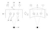
도 2는 본 명세서의 일 실시예에 따른 투명 플렉서블 디스플레이 유닛(120)이 벤딩됨을 디텍트하는 경우, 디스플레이 시스템(100)이 증강 현실 오브젝트를 디스플레이 하는 방법을 나타낸 도면이다.FIG. 2 is a diagram illustrating a method in which the
디스플레이 시스템(100)은 리얼 오브젝트에 대응하는 증강 현실 오브젝트를 투명 플렉서블 디스플레이 유닛(120)에 디스플레이 할 수 있다. 보다 상세하게는, 디스플레이 시스템(100)은 카메라 유닛(110)으로 리얼 오브젝트를 디텍트 할 수 있다. 디스플레이 시스템(100)은 디텍트된 리얼 오브젝트를 바라보는 유저 눈의 시선을 디텍트 할 수 있다. 본 명세서에 따라 일 예로서, 디스플레이 시스템(100)은 센서 유닛을 이용하여 리얼 오브젝트를 바라보는 유저의 시선을 디텍트 할 수 있다. 디스플레이 시스템(100)은 리얼 오브젝트를 바라보는 유저의 시선과 투명 플렉서블 디스플레이 유닛(120)이 교차하는 지점에 기초하여 증강 현실 오브젝트를 디스플레이 할 수 있다. 이때, 디스플레이 시스템(100)은 복수의 리얼 오브젝트를 디텍트 할 수 있다. 디스플레이 시스템(100)은 복수의 리얼 오브젝트를 바라보는 유저의 시선을 디텍트할 수 있다. 디스플레이 시스템(100)은 유저의 시선과 투명 플렉서블 디스플레이 유닛(120)이 교차하는 지점에 기초하여 복수의 증강 현실 오브젝트를 디스플레이 할 수 있다.The
또한, 디스플레이 시스템(100)은 투명 플렉서블 디스플레이 유닛(120)이 벤딩됨을 디텍트 할 수 있다. 디스플레이 시스템(100)이 투명 플렉서블 디스플레이 유닛(120)이 벤딩됨을 디텍트 하는 경우, 디스플레이 시스템(100)은 리얼 오브젝트에 대응하는 증강 현실 오브젝트를 벤딩되는 각도에 기초하여 디스플레이 할 수 있다.Also, the
보다 상세하게는, 유저는 투명 디스플레이 유닛(120)을 통해 리얼 오브젝트를 디텍트 할 수 있다. 디스플레이 시스템(100)은 유저의 시선과 투명 플렉서블 디스플레이 유닛(120)이 교차하는 지점에 기초하여 증강 현실 오브젝트를 디스플레이 할 수 있다. 이때, 투명 플렉서블 디스플레이 유닛(120)이 벤딩됨을 디텍트 하는 경우, 디스플레이 시스템(100)은 리얼 오브젝트를 바라보는 시선과 투명 플렉서블 유닛(120)의 교차점을 벤딩 각도에 기초하여 변경할 수 있다. 디스플레이 시스템(100)은 리얼 오브젝트에 대응하는 증강 현실 오브젝트를 디스플레이 하는 위치를 변경할 수 있다. 이를 통해, 유저는 투명 플렉서블 디스플레이 유닛(120)이 벤딩되어도 리얼 오브젝트에 대응하는 증강 현실 오브젝트를 유저의 시선의 변경없이 바라볼 수 있다.More specifically, the user may detect a real object through the
보다 상세하게는, 일 예로, 도 2를 참조하면, 디스플레이 시스템(100)은 제 1 리얼 오브젝트(220)에 대응하는 제 1 증강 현실 오브젝트(250)를 투명 플렉서블 디스플레이 유닛(100)에 디스플레이할 수 있다. 이때, 제 1 증강 현실 오브젝트(250)는 리얼 오브젝트를 바라보는 유저 시선과 투명 디스플레이 유닛(120)의 교차점에 디스플레이 될 수 있다. 또한, 디스플레이 시스템(100)은 제 2 리얼 오브젝트(230)에 대응하는 제 2 증강 현실 오브젝트(260)를 디스플레이 할 수 있다. 또한, 디스플레이 시스템(100)은 제 3 리얼 오브젝트(240)에 대응하는 제 3 증강 현실 오브젝트(270)를 디스플레이 할 수 있다. 이때, 디스플레이 시스템(100)이 투명 플렉서블 디스플레이 유닛(120)이 벤딩됨을 디텍트 하는 경우, 디스플레이 시스템(100)은 제 1 증강 현실 오브젝트(250)의 위치를 변경하고, 디스플레이 할 수 있다. 이때, 디스플레이 시스템(100)은 리얼 오브젝트를 바라보는 유저의 시선과 제 1 리얼 오브젝트(220)가 교차하는 지점으로 제 1 증강 현실 오브젝트(250)의 위치를 변경하고, 디스플레이할 수 있다. 또한, 디스플레이 시스템(100)은 제 2 증강 현실 오브젝트(260) 및 제 3 증강 현실 오브젝트(270)의 위치를 변경하고, 디스플레이 할 수 있다.More specifically, as an example, referring to FIG. 2 , the
본 명세서에 따라, 일 예로, 디스플레이 시스템(100)은 투명 플렉서블 디스플레이 유닛(120)의 벤딩 방향을 디텍트 할 수 있다. 이때 벤딩 방향은 투명 플렉서블 디스플레이 유닛(120)의 중심점을 지나는 가로 방향 또는 세로 방향의 기준선을 기준으로 결정될 수 있다. 또한, 벤딩 방향은 유저 눈을 향하는 안쪽 방향 또는 유저 눈과 반대 방향인 바깥쪽 방향일 수 있다. 이때, 일 예로서, 디스플레이 시스템(100)은 벤딩 방향 및 벤딩 각도에 기초하여 증강 현실 오브젝트가 디스플레이 되는 위치를 변경할 수 있다. 즉, 디스플레이 시스템(100)은 벤딩된 투명 플렉서블 디스플레이 유닛(120)과 리얼 오브젝트를 바라보는 유저 시선이 교차하는 지점에 기초하여 증강 현실 오브젝트를 디스플레이 할 수 있다.According to the present specification, for example, the
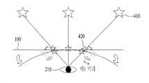
도 3는 본 명세서의 일 실시예에 따른 디스플레이 시스템(100)이 유저 눈과 리얼 오브젝트의 각도에 기초하여 증강 현실 오브젝트를 디스플레이 하는 위치를 설정하는 방법을 나타낸 도면이다.3 is a diagram illustrating a method of setting a position in which the
디스플레이 시스템(100)은 리얼 오브젝트에 대응하는 증강 현실 오브젝트를 투명 플렉서블 디스플레이 유닛(120)에 디스플레이 할 수 있다. 디스플레이 시스템(100)은 투명 플렉서블 디스플레이 유닛(120)이 벤딩됨을 디텍트 할 수 있다. 디스플레이 시스템(100)이 투명 플렉서블 디스플레이 유닛(120)이 벤딩됨을 디텍트 하는 경우, 디스플레이 시스템(100)은 리얼 오브젝트에 대응하는 증강 현실 오브젝트의 위치를 변경하고, 디스플레이 할 수 있다. 보다 상세하게는, 디스플레이 시스템(100)은 리얼 오브젝트를 바라보는 유저의 시선과 투명 플렉서블 디스플레이 유닛(120)이 교차하는 지점에 기초하여 증강 현실 오브젝트를 디스플레이 할 수 있다. 디스플레이 시스템(100)이 투명 플렉서블 디스플레이 유닛(120)이 벤딩됨을 디텍트하는 경우, 디스플레이 시스템(100)은 리얼 오브젝트를 바라보는 유저의 시선과 벤딩된 투명 플렉서블 디스플레이 유닛(120)이 교차하는 지점에 기초하여 증강 현실 오브젝트를 디스플레이 할 수 있다. 즉, 디스플레이 시스템(100)은 투명 플렉서블 디스플레이 유닛(120)이 벤딩됨을 디텍트 하는 경우, 디스플레이 시스템(100)은 증강 현실 오브젝트의 위치를 변경하고 디스플레이 할 수 있다. 이때, 디스플레이 시스템(100)은 유저 눈과 리얼 오브젝트가 이루는 각도에 기초하여 증강 현실 오브젝트를 디스플레이 하는 위치를 변경하고, 디스플레이 할 수 있다.The
유저 눈과 리얼 오브젝트가 이루는 각도가 증가하는 경우, 디스플레이 시스템(100)은 리얼 오브젝트에 대응하는 증강 현실 오브젝트를 투명 플렉서블 디스플레이 유닛(120)의 중심에서 멀리 디스플레이할 수 있다. 이때, 투명 플렉서블 디스플레이 유닛(120)은 투명 플렉서블 디스플레이 유닛(120)의 위치에 따라 벤딩 정도가 다를 수 있다. 투명 플렉서블 디스플레이 유닛(120)이 벤딩되는 경우, 투명 플렉서블 디스플레이 유닛(120)은 중심점으로부터 멀어질수록 벤딩 각도가 커질 수 있다. 이때, 벤딩 각도는 투명 플렉서블 디스플레이 유닛(120)의 중심에서 가장자리로 갈수록 더 커질 수 있다. 투명 플렉서블 디스플레이 유닛(120)의 벤딩 각도가 커지는 경우, 디스플레이 시스템(100)은 증강 현실 오브젝트를 벤딩 전에 디스플레이한 위치에서 멀게 디스플레이할 수 있다. 따라서, 유저 눈과 리얼 오브젝트의 각도가 커지는 경우, 디스플레이 시스템(100)은 벤딩 전에 증강 현실 오브젝트를 디스플레이한 위치에서 멀게 디스플레이할 수 있다. 즉, 디스플레이 시스템(100)은 유저 눈과 리얼 오브젝트의 각도에 기초하여 디스플레이하는 증강 현실 오브젝트의 위치를 조절할 수 있다.When the angle between the user's eyes and the real object increases, the
본 명세서에 따라, 일 예로, 도 3을 참조하면, 디스플레이 시스템(100)은 유저 눈(210)과 제 1 각도를 갖는 제 1 리얼 오브젝트(310)를 디텍트할 수 있다. 디스플레이 시스템(100)은 제 1 각도에 기초하여 제 1 리얼 오브젝트(310)에 대응하는 제 1 증강 현실 오브젝트(330)를 제 1 위치에 디스플레이 할 수 있다. 이때, 제 1 위치는 유저 눈(210)이 제 1 리얼 오브젝트(310)를 바라보는 시선과 투명 플렉서블 디스플레이 유닛(120)의 교차하는 지점에 기초하여 결정될 수 있다. 또한, 디스플레이 시스템(100)은 유저 눈(210)과 제 2 각도를 갖는 제 2 리얼 오브젝트(320)를 디텍트할 수 있다. 디스플레이 시스템(100)은 제 2 각도에 기초하여 제 2 리얼 오브젝트(320)에 대응하는 제 2 증강 현실 오브젝트(340)를 제 2 위치에 디스플레이 할 수 있다. 이때, 제 2 위치는 유저 눈(210)이 제 2 리얼 오브젝트(320)를 바라보는 시선과 투명 플렉서블 디스플레이 유닛(120)의 교차하는 지점에 기초하여 결정될 수 있다. 이때, 제 1 각도가 제 2 각도보다 큰 경우, 제 1 위치는 제 2 위치보다 투명 플렉서블 디스플레이 유닛(120)의 중심으로부터 멀리 위치할 수 있다.According to the present specification, as an example, referring to FIG. 3 , the
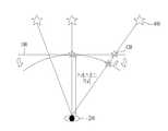
디스플레이 시스템(100)은 투명 플렉서블 디스플레이 유닛(120)이 벤딩됨을 디텍트 할 수 있다. 디스플레이 시스템(100)이 투명 플렉서블 디스플레이 유닛(120)이 벤딩됨을 디텍트 하는 경우, 디스플레이 시스템(100)은 벤딩 각도에 기초하여 제 1 증강 현실 오브젝트(330)를 제 3 위치에 디스플레이 할 수 있다. 이때, 제 3 위치는 제 1 리얼 오브젝트(310)을 바라보는 유저 눈(210)의 시선과 벤딩된 투명 플렉서블 디스플레이 유닛(120)이 교차하는 지점에 기초하여 결정될 수 있다. 또한, 제 3 위치는 제 1 위치로부터 제 1 거리만큼 떨어진 위치일 수 있다. 일 예로, 제 3 위치는 제 1 위치로부터 투명 플렉서블 디스플레이 유닛(120)의 중심 방향으로 제 1 거리만큼 떨어진 거리일 수 있다. 또한, 일 예로, 제 3 위치는 제 1 위치로부터 투명 플렉서블 디스플레이 유닛(120)의 중심점 반대 방향으로 제 1 거리만큼 떨어진 거리일 수 있다.The
또한, 디스플레이 시스템(100)은 벤딩 각도에 기초하여 제 2 증강 현실 오브젝트(340)를 제 4 위치에 디스플레이 할 수 있다. 이때, 제 4 위치는 제 2 리얼 오브젝트(320)을 바라보는 유저 눈(210)의 시선과 벤딩된 투명 플렉서블 디스플레이 유닛(120)이 교차하는 지점에 기초하여 결정될 수 있다. 또한, 제 4 위치는 제 2 위치로부터 제 2 거리만큼 떨어진 위치일 수 있다. 일 예로, 제 4 위치는 제 2 위치로부터 투명 플렉서블 디스플레이 유닛(120)의 중심 방향으로 제 2 거리만큼 떨어진 거리일 수 있다. 또한, 일 예로, 제 4 위치는 제 2 위치로부터 투명 플렉서블 디스플레이 유닛(120)의 중심 반대 방향으로 제 2 거리만큼 떨어진 거리일 수 있다. 이와 관련해서는 도 4a 및 도 4b에서 후술한다.Also, the
이때, 제 1 각도가 제 2 각도보다 큰 경우, 제 1 거리는 제 2 거리보다 클 수 있다. 보다 상세하게는, 상술한 바와 같이 제 1 위치는 제 2 위치보다 투명 플렉서블 디스플레이 유닛(120)의 중심에서 멀리 위치할 수 있다. 이때, 벤딩 각도는 투명 플렉서블 디스플레이 유닛(120)의 중심으로부터 멀리 위치할수록 커질 수 있다. 또한, 디스플레이 시스템(100)은 벤딩 각도가 클수록 벤딩 전에 증강 현실 오브젝트가 디스플레이된 위치에서 멀리 위치한 지점에서 증강 현실 오브젝트를 디스플레이 할 수 있다. 따라서, 제 1 각도가 제 2 각도보다 큰 경우, 제 1 거리는 제 2 거리보다 클 수 있다. 즉, 디스플레이 시스템은 유저 눈(210)과 리얼 오브젝트가 이루는 각도가 클수록 벤딩 전에 증강 현실 오브젝트가 디스플레이된 위치에서 멀리 위치한 지점에서 증강 현실 오브젝트를 디스플레이 할 수 있다.In this case, when the first angle is greater than the second angle, the first distance may be greater than the second distance. More specifically, as described above, the first position may be located farther from the center of the transparent
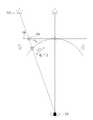
도 4a 내지 도 4c는 본 명세서의 일 실시예에 따른 투명 디스플레이 유닛(120)과 유저 눈 사이의 거리에 기초하여 증강 현실 오브젝트를 디스플레이 하는 방법을 나타낸 도면이다.4A to 4C are diagrams illustrating a method of displaying an augmented reality object based on a distance between the
디스플레이 시스템(100)은 유저 눈(210)이 리얼 오브젝트를 바라보는 시선과 투명 플렉서블 디스플레이 유닛(120)이 교차하는 지점에 기초하여 증강 현실 오브젝트를 디스플레이 할 수 있다. 이때, 디스플레이 시스템(100)은 유저 눈(210)의 위치에 기초하여 증강 현실 오브젝트를 디스플레이 할 수 있다. 보다 상세하게는, 디스플레이 시스템(100)이 투명 플렉서블 디스플레이 유닛(120)이 벤딩됨을 디텍트하는 경우, 디스플레이 시스템(100)은 증강 현실 오브젝트의 위치를 변경하고, 디스플레이 할 수 있다. 이때, 유저 눈(210)과 투명 플렉서블 디스플레이 유닛(120)의 거리가 스레스홀드 거리 이하인 경우, 디스플레이 시스템(100)은 벤딩되기 전의 증강 현실 오브젝트가 디스플레이된 위치로부터 내측에 증강현실 오브젝트를 디스플레이 할 수 있다. 또한, 유저 눈(210)과 투명 플렉서블 디스플레이 유닛(120)의 거리가 스레스홀드 거리 초과인 경우, 디스플레이 시스템(100)은 벤딩되기 전의 증강 현실 오브젝트가 디스플레이된 위치로부터 외측에 증강 현실 오브젝트를 디스플레이 할 수 있다. 이때, 디스플레이 시스템(100)은 투명 플렉서블 디스플레이 유닛(120)의 중심에 기초하여 내측 및 외측을 결정할 수 있다. 보다 상세하게는, 내측은 투명 플렉서블 디스플레이 유닛(120)의 중심 방향으로, 중심에 근접하는 위치일 수 있다. 또한, 외측은 투명 플렉서블 디스플레이 유닛(120)의 중심의 반대 방향으로 투명 플렉서블 유닛(120)의 가장자리에 근접하는 위치일 수 있다. 즉, 디스플레이 시스템(100)은 투명 플렉서블 유닛(120)의 중심을 가장 내측의 위치로 결정할 수 있다. 또한, 디스플레이 시스템(100)은 투명 플렉서블 유닛(120)의 가장자리를 가장 외측의 위치로 결정할 수 있다. 또한, 스레스홀드 거리는 디스플레이 되는 증강 현실 오브젝트의 위치를 변경하는 임계 거리일 수 있다. 또한, 스레스홀드 거리는 일정 오차 범위를 갖도록 설정될 수 있다.The
또한, 일 예로, 스레스홀드 거리는 투명 플렉서블 디스플레이 유닛(120)의 벤딩에 기초하여 결정될 수 있다. 또한, 스레스홀드 거리는 카메라 유닛(110)과 리얼 오브젝트의 각도에 기초하여 결정될 수 있다. 또한, 일 예로, 스레스홀드 거리는 유저 눈(210)과 리얼 오브젝트의 각도에 더 기초하여 결정될 수 있다.Also, as an example, the threshold distance may be determined based on bending of the transparent
보다 상세하게는, 일 예로, 스레스홀드 거리는 투명 플렉서블 유닛(120)의 벤딩 각도 및 카메라 유닛(110)과 리얼 오브젝트의 위치를 고려하여 결정될 수 있다. 스레스홀드 거리는 벤딩되기 전의 증강 현실 오브젝트가 디스플레이 되는 위치, 벤딩 후의 증강 현실 오브젝트가 디스플레이 되는 위치 및 유저 눈(210)이 동일 직선 상에 위치하는 지점으로 설정될 수 있다.More specifically, as an example, the threshold distance may be determined in consideration of the bending angle of the transparent
일 예로, 도 4a 내지 도 4c를 참조하면, 디스플레이 시스템(100)은 제 1 리얼 오브젝트(410)에 대응하는 제 1 증강 현실 오브젝트(420)를 제 1 위치에 디스플레이 할 수 있다. 이때, 제 1 위치는 유저 눈(210)이 제 1 리얼 오브젝트(410)를 바라보는 시선과 투명 플렉서블 디스플레이 유닛(120)이 교차하는 지점에 기초하여 결정될 수 있다. 일 예로, 제 1 위치는 유저 눈(210)이 제 1 리얼 오브젝트(410)를 바라보는 시선과 투명 플렉서블 디스플레이 유닛(120)이 교차하는 지점에 기초하여 결정될 수 있다. 또한, 일 예로, 제 1 위치는 유저의 좌측 눈 및 우측 눈의 중심과 제 1 리얼 오브젝트(410)를 연결하는 선과 투명 플렉서블 디스플레이 유닛(120)이 교차하는 지점일 수 있다. 또 다른 일 예로, 제 1 증강 현실 오브젝트(420)가 3D로 디스플레이 되는 경우, 제 1 위치는 유저의 좌측 눈과 제 1 리얼 오브젝트(410)의 거리 및 각도와 유저의 우측 눈과 제 1 리얼 오브젝트(410)의 거리 및 각도에 의해 결정될 수 있다. 즉, 제 1 위치는 유저 눈에 기초하여 디스플레이 시스템(100)에 의해 변경되어 설정될 수 있다.For example, referring to FIGS. 4A to 4C , the
또한, 디스플레이 시스템(100)이 투명 플렉서블 디스플레이 유닛(120)이 벤딩됨을 디텍트하는 경우, 디스플레이 시스템은 제 1 증강 현실 오브젝트(420)를 제 2 위치에 디스플레이 할 수 있다. 이때, 제 2 위치는 유저 눈(210)이 제 1 리얼 오브젝트(410)를 바라보는 시선과 벤딩된 투명 플렉서블 디스플레이 유닛(120)이 교차하는 지점에 기초하여 결정될 수 있다. 이때, 유저 눈이 투명 플렉서블 디스플레이 유닛(120)과 멀리 떨어진 위치에서 디텍트되는 경우, 디스플레이 시스템(100)은 증강 현실 오브젝트를 제 1 위치의 외측으로 제 1 거리만큼 떨어진 제 2 위치에 디스플레이 할 수 있다. 즉, 제 1 거리는 제 1 위치로부터 투명 플렉서블 디스플레이 유닛(120)의 중심의 반대 방향으로 떨어진 위치일 수 있다.Also, when the
반면, 유저 눈이 투명 플렉서블 디스플레이 유닛(120)과 근접하는 위치에서 디텍트 되는 경우, 디스플레이 시스템은 증강 현실 오브젝트를 제 1 위치의 내측으로 제 1 거리만큼 떨어진 제 2 위치에 디스플레이 할 수 있다. 즉, 제 1 거리는 제 1 위치로부터 투명 플렉서블 디스플레이 유닛(120)의 중심 방향으로 떨어진 위치일 수 있다.On the other hand, when the user's eye is detected at a position close to the transparent
보다 상세하게는, 유저 눈(210)과 투명 플렉서블 디스플레이 유닛(120)이 스레스홀드 거리 초과인 경우, 디스플레이 시스템(100)은 증강 현실 오브젝트를 제 1 위치의 외측으로 제 1 거리만큼 떨어진 제 2 위치에 디스플레이 할 수 있다. 또한, 유저 눈(210)과 투명 플렉서블 디스플레이 유닛(120)이 스레스홀드 거리 이하인 경우, 디스플레이 시스템(100)은 증강 현실 오브젝트를 제 1 위치의 내측으로 제 1 거리만큼 떨어진 제 2 위치에 디스플레이 할 수 있다. 이때, 스레스홀드 거리는 증강 현실 오브젝트가 디스플레이 되는 위치가 변경될 수 있는 임계 거리일 수 있다. 스레스홀드 거리는 투명 플렉서블 디스플레이 유닛(120)의 벤딩 정도, 카메라 유닛(120)과 제 1 리얼 오브젝트(410)의 각도에 의해 결정될 수 있다. 보다 상세하게는, 스레스 홀드 거리는 유저 눈(210), 제 1 위치, 제 2 위치 및 제 1 리얼 오브젝트(410)가 동일 선상에 위치하는 지점에서의 투명 플렉서블 유닛(120)과 유저 눈(210)까지의 거리일 수 있다. 즉, 스레스홀드 거리는 투명 플렉서블 디스플레이 유닛(120)의 벤딩 정도 및 카메라 유닛(110)과 제 1 리얼 오브젝트(410)의 각도를 고려하려 설정될 수 있다.More specifically, when the user's
도 5a 및 도 5b는 본 명세서의 일 실시예에 따른 디스플레이 시스템(100)이 투명 플렉서블 디스플레이 유닛(120)의 벤딩에 기초하여 증강 현실 오브젝트를 디스플레이 하는 방법을 나타낸 도면이다.5A and 5B are diagrams illustrating a method in which the
디스플레이 시스템(100)이 투명 플렉서블 디스플레이 유닛(120)의 벤딩됨을 디텍트 하는 경우, 디스플레이 시스템(100)은 증강 현실 오브젝트의 위치를 변경하고, 디스플레이 할 수 있다. 이때, 디스플레이 시스템(100)은 벤딩된 투명 플렉서블 디스플레이 유닛(120)과 유저 눈(210)이 리얼 오브젝트를 바라보는 시선이 교차하는 지점에 기초하여 증강 현실 오브젝트가 디스플레이 되는 위치를 변경될 수 있다. 따라서, 디스플레이 시스템(100)은 증강 현실 오브젝트가 디스플레이 되는 위치를 투명 플렉서블 디스플레이 유닛(120)의 벤딩에 기초하여 변경할 수 있다. 보다 상세하게는, 디스플레이 시스템(100)은 증강 현실 오브젝트가 디스플레이 되는 위치를 투명 플렉서블 디스플레이 유닛(120)의 벤딩 각도에 기초하여 결정될 수 있다. 이때, 벤딩 각도는 투명 플렉서블 디스플레이 유닛(120) 내부 위치에 따라 다를 수 있다. 이때, 일 예로, 벤딩 각도는 투명 플렉서블 디스플레이 유닛(120) 내부 위치 각각에 대한 벤딩된 각도의 평균일 수 있다. 또한, 일 예로, 벤딩 각도는 투명 플렉서블 디스플레이 유닛(120)의 내부 위치 중 증강 현실 오브젝트가 디스플레이 되는 지점에서의 벤딩 각도일 수 있다. 또한, 일 예로, 벤딩 각도는 투명 플렉서블 디스플레이 유닛(120)의 벤딩이 커지면 증가할 수 있으며, 상술한 실시예로 한정되지 않는다.When the
투명 플렉서블 디스플레이 유닛(120)의 벤딩 각도가 커지는 경우, 디스플레이 시스템(100)은 디스플레이 하는 증강 현실 오브젝트의 위치를 투명 플렉서블 디스플레이 유닛(120)의 가장자리에 근접하게 디스플레이 할 수 있다. 보다 상세하게는 증강 현실 오브젝트는 벤딩된 투명 플렉서블 디스플레이 유닛(120)과 유저 눈(210)이 리얼 오브젝트를 바라보는 시선이 교차하는 지점에 기초하여 디스플레이 될 수 있다. 띠라서, 투명 플렉서블 디스플레이 유닛(120)의 벤딩 각도가 증가하는 경우, 증강 현실 오브젝트는 투명 플렉서블 디스플레이 유닛(120)의 가장자리 근접하게 디스플레이 될 수 있다.When the bending angle of the transparent
또한, 일 예로, 디스플레이 시스템(100)은 증강 현실 오브젝트가 디스플레이 되는 위치를 투명 플렉서블 디스플레이 유닛(120)의 벤딩 방향에 기초하여 결정할 수 있다.Also, as an example, the
또한, 일 예로, 벤딩 각도가 증가하여 유저 눈(210)이 리얼 오브젝트를 바라보는 시선과 투명 플렉서블 디스플레이 유닛(120)이 교차하는 지점이 존재하지 않는 경우, 디스플레이 시스템(100)은 인디케이터를 디스플레이 할 수 있다. 이때, 인디케이터는 증강 현실 오브젝트를 디스플레이 할 수 없음을 나타낼 수 있다. 디스플레이 시스템은 피드백을 유저에게 전달할 수 있다. 피드백은 비주얼 피드백, 오디오 피드백 및 택타일 피드백 중 적어도 하나를 포함할 수 있다. 이때, 피드백는 증강 현실 오브젝트를 디스플레이할 수 없음을 나타낼 수 있다.Also, as an example, when there is no intersection point between the user's
일 예로, 도 5a 및 도 5b를 참조하면, 디스플레이 시스템(100)은 제 1 리얼 오브젝트(510)에 대응하는 제 1 증강 현실 오브젝트(520)를 제 1 위치에 디스플레이 할 수 있다. 이때, 디스플레이 시스템(100)이 투명 플렉서블 디스플레이 유닛(120)이 벤딩됨을 디텍트하는 경우, 디스플레이 시스템(100)은 제 1 증강 현실 오브젝트(520)를 제 2 위치에 디스플레이 할 수 있다. 제 2 위치는 유저 눈(210)이 제 1 리얼 오브젝트(510)를 바라보는 시선과 투명 플렉서블 디스플레이 유닛(120)이 교차하는 지점에 기초하여 결정될 수 있다. 또한, 제 2 위치는 제 1 위치로부터 제 1 거리만큼 떨어진 위치일 수 있다.For example, referring to FIGS. 5A and 5B , the
이때, 투명 플렉서블 디스플레이 유닛(120)의 벤딩 각도가 증가하는 경우, 디스플레이 시스템(100)은 제 1 거리를 크게 설정할 수 있다. 즉, 디스플레이 시스템(100)은 벤딩 각도가 커질 수록 제 2 위치를 제 1 위치로부터 멀게 설정할 수 있다. 이때, 벤딩 각도가 증가하여 제 2 위치가 투명 플렉서블 디스플레이 유닛(120)에 존재하지 않는 경우, 디스플레이 시스템(100)은 제 1 증강 현실 오브젝트(520)를 디스플레이 할 수 없다는 인디케이터를 디스플레이 할 수 있다. 또한, 디스플레이 시스템(100)은 제 1 증강 현실 오브젝트(520)를 디스플레이할 수 없다는 피드백을 유저에게 전달 할 수 있다.In this case, when the bending angle of the transparent
도 6a 및 도 6b는 본 명세서의 일 실시예에 따른 HMD 디바이스를 포함하는 디스플레이 시스템(100)을 나타낸 도면이다.6A and 6B are diagrams illustrating a
디스플레이 시스템(100)은 비주얼 정보를 디스플레이 하는 디바이스일 수 있다. 이때, 디스플레이 시스템(100)은 카메라 유닛(110) 및 벤딩 센서 유닛(130)을 포함하는 HMD 디바이스(610) 및 투명 플렉서블 디스플레이 유닛(120)을 포함하는 디스플레이 유닛(620)으로 구성될 수 있다. 보다 상세하게는, 디스플레이 시스템(100)은 HMD 디바이스(610)와 디스플레이 유닛(620)으로 구성된 시스템일 수 있다. 이때, 일 예로, HMD 디바이스(610)는 디스플레이 유닛(620)과 분리된 유닛일 수 있다. 이때, HMD 디바이스(610)는 유저에게 착용될 수 있는 웨어러블 디바이스일 수 있다.The
본 명세서의 일 실시예에 따라, HMD 디바이스(610)는 카메라 유닛(110)을 이용하여 리얼 오브젝트(630)를 디텍트할 수 있다. 또한, HMD 디바이스(610)는 리얼 오브젝트(630)에 대응하는 증강 현실 오브젝트(640)를 디스플레이 유닛(620)에 디스플레이 할 수 있다. 이때, 일 예로, HMD 디바이스(610)는 커뮤니케이션 유닛(미도시)를 포함할 수 있다. 이때, 커뮤니케이션 유닛은 디스플레이 유닛(620)과 다양한 프로토콜을 사용하여 통신을 수행하고, 이를 통해 데이터를 송/수신할 수 있다. 또한, 커뮤니케이션 유닛은 유선 또는 무선으로 네트워크에 접속하여, 컨텐츠 등의 디지털 데이터를 송/수신할 수 있다. 본 명세서에서, HMD 디바이스(610)는 리얼 오브젝트(640)를 디텍트할 수 있다. 이때, HMD 디바이스(610)는 디스플레이 유닛(620)에 좌표를 설정할 수 있다. 보다 상세하게는, HMD 디바이스(610)는 디스플레이 유닛(620)의 중심을 기준으로 수직축 및 수평축을 따라 좌표를 설정할 수 있다. HMD 디바이스(610)가 리얼 오브젝트(630)를 디텍트한 경우, HMD 디바이스(100)는 디텍트한 리얼 오브젝트에 대응하는 증강 현실 오브젝트의 위치를 디스플레이 유닛(620)의 좌표를 기준으로 디스플레이 할 수 있다. 이때, HMD 디바이스(100)는 설정된 좌표를 커뮤니케이션 유닛을 통해 디스플레이 유닛(620)으로 전달할 수 있다. 디스플레이 유닛(620)은 전달 받은 좌표에 기초하여 리얼 오브젝트(630)에 대응하는 증강 현실 오브젝트(640)를 디스플레이 할 수 있다. 또한, HMD 디바이스(100)는 벤딩 센서 유닛(130)을 이용하여 디스플레이 유닛(620)이 벤딩됨을 디텍트할 수 있다. 이때, HMD 디바이스(100)는 디스플레이 유닛(620)의 벤딩 각도에 기초하여 리얼 오브젝트(630)에 대응하는 증강 현실 오브젝트(640)가 디스플레이 되는 위치를 변경할 수 있다. 이때, HMD 디바이스(100)는 디스플레이 유닛(620)의 좌표를 기준으로 증강 현실 오브젝트가 디스플레이 되는 위치를 결정할 수 있다. HMD 디바이스(100)는 설정된 좌표를 커뮤니케이션 유닛을 통해 디스플레이 유닛(620)으로 전달할 수 있다. 디스플레이 유닛(620)은 전달 받은 좌표에 기초하여 리얼 오브젝트(630)에 대응하는 증강 현실 오브젝트(640)를 벤딩된 디스플레이 유닛(620)에 디스플레이할 수 있다.According to an embodiment of the present specification, the
도 7a 및 도 7b은 본 명세서의 일 실시예에 따른 디스플레이 시스템(100)이 카메라 유닛(110)의 화각에 기초하여 증강 현실 오브젝트를 디스플레이 하는 방법을 나타낸 도면이다.7A and 7B are diagrams illustrating a method for the
디스플레이 시스템(100)은 카메라 유닛(110)의 화각 내에 위치하는 리얼 오브젝트를 디텍트할 수 있다. 이때, 화각은 카메라 유닛(110)의 중심에 기초하여 결정될 수 있다. 또한, 화각은 카메라 유닛(110)이 리얼 오브젝트를 디텍트 할 수 있는 영역을 의미할 수 있다. 디스플레이 시스템(100)은 디텍트한 리얼 오브젝트에 대응되는 증강 현실 오브젝트를 디스플레이 할 수 있다. 이때, 디스플레이 시스템(100)은 유저 눈(210)이 리얼 오브젝트를 바라보는 시선과 투명 플렉서블 디스플레이 유닛(120)이 교차하는 지점에 기초하여 증강 현실 오브젝트를 디스플레이 할 수 있다. 유저 눈(210)이 리얼 오브젝트를 바라보는 시선과 투명 플렉서블 디스플레이 유닛(120)이 교차하는 지점이 존재하지 않는 경우, 디스플레이 시스템(100)은 증강 현실 오브젝트를 디스플레이 할 수 없을 수 있다. 즉, 디스플레이 시스템(100)은 유저 눈(210)이 투명 플렉서블 디스플레이 유닛(120)을 통해 볼 수 있는 리얼 오브젝트에 대응하는 증강 현실 오브젝트만을 디스플레이 할 수 있다. 이때, 리얼 오브젝트는 카메라 유닛(110)의 화각 내에 위치하고, 유저의 시야각 외에 위치할 수 있다. 이때, 유저의 시야각은 투명 플렉서블 디스플레이 유닛(120)을 통해 유저가 디텍트 할 수 있는 영역을 의미할 수 있다.The
이때, 디스플레이 시스템(100)이 투명 플렉서블 디스플레이 유닛(120)이 벤딩됨을 디텍트하는 경우, 디스플레이 시스템(100)은 카메라 유닛(110)의 화각 내에 위치하고, 유저의 시야각 외에 위치하는 리얼 오브젝트를 디스플레이 할 수 있다. 보다 상세하게는, 유저의 시야각은 투명 플렉서블 디스플레이 유닛(120)이 벤딩되면 커질 수 있다. 즉, 유저가 투명 플렉서블 유닛(120)을 통해 디텍트할 수 있는 영역이 증가될 수 있다. 또한, 카메라 유닛(110)은 투명 플렉서블 디스플레이 유닛(120)의 중심을 지나는 수직축에 위치할 수 있다. 또한 일 예로, 카메라 유닛(110)은 투명 플렉서블 디스플레이 유닛(120)의 중심을 지나는 수평축에 위치할 수 있다. 카메라 유닛(110)이 투명 플렉서블 디스플레이 유닛(120)의 수직축에 위치하는 경우, 카메라 유닛(110)의 화각은 투명 플렉서블 디스플레이 유닛(120)이 수직축을 기준으로 벤딩되어도 디텍트하는 영역은 일정할 수 있다. 또한 일 예로, 카메라 유닛(110)이 투명 플렉서블 디스플레이 유닛(120)의 수평축에 위치하는 경우, 카메라 유닛(110)의 화각은 투명 플렉서블 디스플레이 유닛(120)이 수평축을 기준으로 벤딩되어도 디텍트되는 영역은 일정할 수 있다. 투명 플렉서블 디스플레이 유닛(120)이 벤딩됨을 디텍트하는 경우, 유저의 시야각 외에 위치하는 리얼 오브젝트는 카메라 유닛(110)의 화각 및 유저의 시야각 내에 위치할 수 있다. 따라서 디스플레이 시스템(100)은 리얼 오브젝트에 대응하는 증강 현실 오브젝트를 디스플레이 할 수 있다.At this time, when the
또한, 본 명세서에 따라 일 예로, 유저의 시야각은 투명 플렉서블 디스플레이 유닛(120)의 벤딩 각도가 증가함에 따라 증가할 수 있다.Also, according to the present specification, as an example, the viewing angle of the user may increase as the bending angle of the transparent
본 명세서에 따라, 일 예로, 도 7a 및 도 7b를 참조하면, 디스플레이 시스템은 제 1 리얼 오브젝트(710)에 대응하는 제 1 증강 현실 오브젝트(750)를 투명 플렉서블 디스플레이 유닛(120)에 디스플레이 할 수 있다. 이때, 제 1 리얼 오브젝트(710)는 카메라 유닛(110)의 화각 및 유저의 시야각 내에 위치할 수 있다. 디스플레이 시스템은 제 2 리얼 오브젝트(720)에 대응하는 제 2 증강 현실 오브젝트(760)의 일부 영역을 디스플레이 할 수 있다. 일 예로, 제 2 리얼 오브젝트(720)는 카메라 유닛(110)의 화각 내에 위치하고, 유저의 시야각의 경계에 위치할 수 있다. 즉, 디스플레이 시스템(100)은 제 2 리얼 오브젝트(720) 중 유저의 시야각이 미치는 부분에 대응하는 제 2 증강 현실 오브젝트(760) 일부만을 디스플레이 할 수 있다.According to the present specification, as an example, referring to FIGS. 7A and 7B , the display system may display the first augmented
또한, 디스플레이 시스템(100)은 제 3 리얼 오브젝트(730)를 디텍트 할 수 있다. 이때, 제 3 리얼 오브젝트(730)는 카메라 유닛(110)의 화각 내에 위치하고, 유저의 시야각 외에 위치할 수 있다. 따라서, 디스플레이 시스템(100)은 제 3 리얼 오브젝트(730)를 디텍트 할 수 있지만 제 3 리얼 오브젝트(730)에 대응하는 제 3 증강 현실 오브젝트(770)를 투명 디스플레이 유닛(120)에 디스플레이할 수 없을 수 있다.Also, the
또한, 디스플레이 시스템(100)은 제 4 리얼 오브젝트(740)를 디텍트할 수 없을 수 있다. 또한, 디스플레이 시스템(100)은 제 4 리얼 오브젝트(740)에 대응하는 제 4 증강 현실 오브젝트(780)를 디스플레이할 수 없을 수 있다. 제 4 리얼 오브젝트(740)는 카메라 유닛(110)의 화각 및 유저의 시야각 외에 위치할 수 있다.Also, the
이때, 디스플레이 시스템(100)이 투명 플렉서블 디스플레이 유닛(120)이 벤딩됨을 디텍트 하는 경우, 디스플레이 시스템(100)은 제 3 리얼 오브젝트(730)에 대응하는 제 3 증강 현실 오브젝트(770)를 투명 플렉서블 디스플레이 유닛(120)에 디스플레이 할 수 있다. 보다 상세하게는, 투명 플렉서블 디스플레이 유닛(120)이 벤딩됨을 디텍트하는 경우, 유저의 시야각은 증가할 수 있다. 즉, 유저는 투명 플렉서블 디스플레이 유닛(120)을 통해 더 많은 영역을 디텍트할 수 있다. 따라서, 투명 플렉서블 디스플레이 유닛(120)이 벤딩되는 경우, 제 3 리얼 오브젝트(730)은 카메라 유닛(110)의 화각 내 및 유저의 시야각 내에 위치할 수 있다. 이를 통해, 디스플레이 시스템(100)은 제 3 리얼 오브젝트(730)에 대응하는 제 3 증강 현실 오브젝트(770)를 투명 디스플레이 유닛(120)에 디스플레이 할 수 있다.At this time, when the
도 8은 본 명세서의 일 실시예에 따른 디스플레이 시스템(100)이 유저 눈과 투명 플렉서블 유닛(120)의 거리에 기초하여 증강 현실 오브젝트를 디스플레이 하는 방법을 나타낸 도면이다. 디스플레이 시스템(100)은 리얼 오브젝트에 대응하는 증강 현실 오브젝트를 투명 플렉서블 디스플레이 유닛(120)에 디스플레이할 수 있다. 이때, 디스플레이 시스템(100)은 카메라 유닛(110)의 화각 내에 위치하는 리얼 오브젝트를 디텍트 할 수 있다. 디스플레이 시스템(100)은 디텍트된 리얼 오브젝트에 대응하는 증강 현실 오브젝트를 디스플레이 할 수 있다. 또한, 디스플레이 시스템(100)은 유저의 시야각 내에 위치하는 리얼 오브젝트를 디텍트 할 수 있다. 디스플레이 시스템(100)은 디텍트한 리얼 오브젝트에 대응하는 증강 현실 오브젝트를 디스플레이 할 있다. 보다 상세하게는, 디스플레이 시스템(100)은 카메라 유닛(110)의 화각 내 및 유저의 시야각 내에 위치하는 리얼 오브젝트를 디텍트 할 수 있다. 디스플레이 시스템은 디텍트한 리얼 오브젝트에 대응하는 증강 현실 오브젝트를 디스플레이 할 수 있다.FIG. 8 is a diagram illustrating a method in which the
이때, 유저 눈(210)과 투명 플렉서블 디스플레이 유닛(120)이 스레스홀드 거리 이하인 경우, 유저의 시야각은 카메라 유닛(110)의 화각보다 커질 수 있다. 보다 상세하게는, 유저 눈(210)은 카메라 유닛(110) 보다 뒤에 위치할 수 있다. 따라서, 유저 눈(210)과 투명 플렉서블 디스플레이 유닛(120) 스레스홀드 거리 이하인 경우, 유저의 시야각은 카메라 유닛(110)의 화각보다 커질 수 있다. 이때, 스레스홀드 거리는 유저의 시야각이 카메라 유닛(110)의 화각보다 커지는 임계 거리일 수 있다. 또한, 스레스홀드 거리는 일정한 오차를 가질 수 있다. 또한, 유저 눈(210)과 투명 플렉서블 디스플레이 유닛(120)이 스레스홀드 거리 초과하는 경우, 유저의 시야각은 카메라 유닛(110)의 화각보다 작아질 수 있다. 또한, 유저의 시야각은 투명 플렉서블 디스플레이 유닛(120)의 벤딩 각도에 기초하여 결정될 수 있다.In this case, when the user's
유저의 시야각이 카메라 유닛(110)의 화각보다 큰 경우, 리얼 오브젝트는 카메라 유닛(110)의 화각 외에 위치하고, 유저의 시야각 내에 위치할 수 있다. 이때, 디스플레이 시스템(100)은 리얼 오브젝트에 대응하는 증강 현실 오브젝트를 디스플레이 할 수 없다. 보다 상세하게는, 유저의 시선이 리얼 오브젝트를 바라보는 시선은 투명 플렉서블 디스플레이 유닛(120)과 교차하지만, 카메라 유닛(110)은 리얼 오브젝트를 디텍트할 수 없을 수 있다. 따라서, 디스플레이 시스템(100)은 리얼 오브젝트에 대응하는 증강 현실 오브젝트를 디스플레이 할 수 없을 수 있다.When the user's viewing angle is greater than the viewing angle of the
또한, 일 예로, 디스플레이 시스템(100)은 카메라 유닛(110)의 화각에 기초하여 인디케이터를 투명 플렉서블 디스플레이 유닛(120)에 디스플레이 할 수 있다. 이때, 인디케이터는 카메라 유닛(110)의 화각이 디텍트 할 수 있는 영역을 의미할 수 있다. 이를 통해, 유저는 디스플레이 시스템(100)이 디스플레이 할 수 있는 리얼 오브젝트의 영역을 설정할 수 있다. 또한, 일 예로, 디스플레이 시스템(100)은 유저 눈(210)과 투명 플렉서블 디스플레이 유닛(120)의 거리에 기초하여 인디케이터를 디스플레이 할 수 있다. 이때, 유저 눈(210)과 투명 플렉서블 디스플레이 유닛(120)의 거리가 증가하는 경우, 디스플레이 시스템(100)은 인디케이터를 투명 플렉서블 디스플레이 유닛(120)의 가장자리에 근접한 위치에 디스플레이 할 수 있다. 또한, 유저 눈(210)과 투명 플렉서블 디스플레이 유닛(120)의 거리가 감소하는 경우, 디스플레이 시스템(100)은 인디케이터를 투명 플렉서블 디스플레이 유닛(120)의 중심점에 근접한 위치에 디스플레이 할 수 있다. 또한, 유저 눈(210)과 투명 플렉서블 디스플레이 유닛(120)의 거리가 스레스홀드 거리 초과인 경우, 디스플레이 시스템(100)은 인디케이터를 디스플레이 하지 않을 수 있다.Also, as an example, the
본 명세서의 일 실시예에 따라, 도 8을 참조하면, 디스플레이 시스템(100)은 제 1 리얼 오브젝트(810)를 디텍트할 수 있다. 디스플레이 시스템(100)은 제 1 리얼 오브젝트(810)에 대응하는 제 1 증강 현실 오브젝트(840)를 투명 플렉서블 디스플레이 유닛(120)에 디스플레이 할 수 있다. 이때, 제 1 리얼 오브젝트(810)는 카메라 유닛(110)의 화각 내에 위치하고, 유저의 시야각 내에 위치할 수 있다. 디스플레이 시스템(100)은 제 2 리얼 오브젝트(820)에 대응하는 제 2 증강 현실 오브젝트(850)를 디스플레이 할 수 없을 수 있다. 이때, 제 2 리얼 오브젝트(820)는 카메라 유닛(110)의 화각 외에 위치하고, 유저의 시야갹 내에 위치할 수 있다. 따라서, 유저 눈이 제 2 리얼 오브젝트(820)를 바라보는 시선은 투명 플렉서블 디스플레이 유닛(120)과 교차하지만, 디스플레이 시스템(100)은 제 2 리얼 오브젝트에 대응하는 제 2 증강 현실 오브젝트(850)를 디스플레이할 수 없을 수 있다. 디스플레이 시스템(100)은 제 3 리얼 오브젝트(830)에 대응하는 제 3 증강 현실 오브젝트(860)를 디스플레이할 수 없을 수 있다. 이때, 제 3 리얼 오브젝트(830)는 카메라 유닛(110)의 화각 외에 위치하고, 유저의 시야각 외에 위치할 수 있다.According to an embodiment of the present specification, referring to FIG. 8 , the
또한, 디스플레이 시스템(100)은 인디케이터(870)를 디스플레이 할 수 있다. 이때 인디케이터(870)는 카메라 유닛(110)의 화각에 기초하여 디스플레이 될 수 있다. 또한, 인디케이터(870)는 디스플레이 시스템(100)이 증강 현실 오브젝트를 디스플레이 하는 영역을 나타낼 수 있다. 즉, 디스플레이 시스템(100)은 인디케이터(870) 내에 위치하는 제 1 증강 현실 오브젝트(840)를 투명 플렉서블 디스플레이 유닛(120)으로 디스플레이할 수 있다.Also, the
도 9는 본 명세서의 일 실시예에 따른 디스플레이 시스템의 제어 방법의 실시예를 나타내는 도면이다. 디스플레이 시스템(100)은 카메라 유닛(110)과 제 1 각도를 갖는 제 1 리얼 오브젝트를 디텍트 할 수 있다.(S910) 이때, 도 1 에서 상술한 바와 같이, 카메라 유닛(110)은 카메라 유닛(110)의 중심을 기준으로 제 1 각도를 디텍트 할 수 있다. 이때, 제 1 각도는 카메라 유닛(110)의 중심을 기준으로 우측, 좌측, 위측 또는 아래측 방향일 수 있다. 또한, 일 예로, 카메라 유닛(110)은 투명 플렉서블 디스플레이 유닛(120)의 중심을 지나는 수직축 상에 위치할 수 있다. 보다 상세하게는, 카메라 유닛(110)은 투명 플렉서블 디스플레이 유닛(120)의 중심을 지나는 수직축의 가장 윗부분에 위치할 수 있다. 이를 통해, 투명 플렉서블 디스플레이 유닛(120)이 벤딩되는 경우, 카메라 유닛(110)은 리얼 오브젝트와 일정한 각도를 유지할 수 있다.9 is a diagram illustrating an embodiment of a method for controlling a display system according to an embodiment of the present specification. The
또한, 일 예로, 카메라 유닛(110)과 리얼 오브젝트의 각도는 투명 플렉서블 유닛(120)의 중심과 유저의 시선을 연결하는 라인에 더 기초하여 결정될 수 있다. 보다 상세하게는, 카메라 유닛(110)은 유저 눈과 투명 플렉서블 디스플레이 유닛(120)의 위치 정보에 기초하여 카메라 유닛(110)과 리얼 오브젝트의 각도를 디텍트할 수 있다. 또한, 일 예로, 카메라 유닛(110)은 리얼 오브젝트를 디텍트하는 센서 유닛을 포함할 수 있다.Also, as an example, the angle between the
다음으로, 디스플레이 시스템(100)은 제 1 리얼 오브젝트에 대응하는 제 1 증강 현실 오브젝트를 제 1 위치에 디스플레이 할 수 있다.(S920) 이때, 도 4a 내지 도 4c에서 상술한 바와 같이, 제 1 위치는 유저 눈(210)이 제 1 리얼 오브젝트를 바라보는 시선과 투명 플렉서블 디스플레이 유닛(120)이 교차하는 지점에 기초하여 결정될 수 있다. 이때, 일 예로, 제 1 위치는 유저 눈(210)이 제 1 리얼 오브젝트를 바라보는 시선과 투명 플렉서블 디스플레이 유닛(120)이 교차하는 지점일 수 있다. 또한, 일 예로, 제 1 위치는 유저의 좌측 눈 및 우측 눈의 중심점과 제 1 리얼 오브젝트(410)를 연결하는 선과 투명 플렉서블 디스플레이 유닛(120)이 교차하는 지점일 수 있다. 또 다른 일 예로, 제 1 증강 현실 오브젝트가 3D로 디스플레이하는 경우, 제 1 위치는 유저의 좌측 눈과 제 1 리얼 오브젝트(410)의 거리 및 각도와 유저의 우측 눈과 제 1 리얼 오브젝트(410)의 거리 및 각도에 의해 결정될 수 있다. 즉, 제 1 위치는 유저 눈에 기초하여 디스플레이 시스템(100)에 의해 변경되어 설정될 수 있다.Next, the
다음으로, 디스플레이 시스템(100)은 투명 플렉서블 디스플레이 유닛(120)이 벤딩됨을 디텍트할 수 있다.(S930) 이때, 도 1에서 상술한 바와 같이, 벤딩 센서 유닛(130)은 투명 플렉서블 디스플레이 유닛(120)이 벤딩되는 각도를 디텍트할 수 있다. 또한, 벤딩 센서 유닛(130)은 투명 플렉서블 디스플레이 유닛(120)이 벤딩되는 방향을 디텍트할 수 있다. 이때, 상술한 방향은 투명 플렉서블 디스플레이 유닛(120)의 중심점을 지나는 수직축을 기준으로 벤딩되는 방향일 수 있다. 이때, 벤딩 방향은 유저 쪽을 향하는 안쪽 방향일 수 있다. 또한, 벤딩 방향은 유저 바깥 쪽을 향하는 바깥쪽 방향일 수 있다. 또한, 벤딩 방향은 투명 플렉서블 디스플레이 유닛(120)의 중심점을 지나는 수평축을 기준으로 벤딩되는 방향일 수 있다. 이때, 벤딩 방향은 유저 쪽을 향하는 안쪽 방향일 수 있다. 또한, 벤딩 방향은 유저 바깥 쪽을 향하는 바깥쪽 방향일 수 있다.Next, the
또한, 도 5a 및 도 5b에서 상술한 바와 같이, 벤딩 각도는 투명 플렉서블 디스플레이 유닛(120) 내부 위치에 따라 다를 수 있다. 이때, 일 예로, 벤딩 각도는 투명 플렉서블 디스플레이 유닛(120) 내부 위치 각각에 대한 벤딩된 각도의 평균일 수 있다. 또한, 일 예로, 벤딩 각도는 투명 플렉서블 디스플레이 유닛(120)의 내부 위치 중 증강 현실 오브젝트가 디스플레이 되는 지점에서의 벤딩 각도일 수 있다. 또한, 일 예로, 벤딩 각도는 투명 플렉서블 디스플레이 유닛(120)의 벤딩이 커지면 증가할 수 있으며, 상술한 실시예로 한정되지 않는다.In addition, as described above with reference to FIGS. 5A and 5B , the bending angle may vary according to an internal position of the transparent
다음으로, 디스플레이 시스템(100)은 제 1 위치와 제 1 거리만큼 떨어진 제 3 위치에 제 1 증강 현실 오브젝트를 디스플레이할 수 있다.(S940) 이때, 도 3에서 상술한 바와 같이, 제 1 위치는 유저 눈(210)이 제 1 리얼 오브젝트(310)를 바라보는 시선과 투명 플렉서블 디스플레이 유닛(120)의 교차하는 지점에 기초하여 결정될 수 있다. 디스플레이 시스템(100)이 투명 플렉서블 디스플레이 유닛(120)이 벤딩됨을 디텍트하는 경우, 디스플레이 시스템(100)은 벤딩되는 각도에 기초하여 제 1 증강 현실 오브젝트(330)를 제 3 위치에 디스플레이할 수 있다. 이때, 제 3 위치는 제 1 리얼 오브젝트(310)을 바라보는 유저 눈(210)의 시선과 벤딩된 투명 플렉서블 디스플레이 유닛(120)이 교차하는 지점에 기초하여 결정될 수 있다. 또한, 제 3 위치는 제 1 위치로부터 제 1 거리만큼 떨어진 위치일 수 있다. 일 예로, 제 3 위치는 제 1 위치로부터 투명 플렉서블 디스플레이 유닛(120)의 중심점 방향으로 제 1 거리만큼 떨어진 거리일 수 있다. 또한, 일 예로, 제 3 위치는 제 1 위치로부터 투명 플렉서블 디스플레이 유닛(120)의 중심점 반대 방향으로 제 1 거리만큼 떨어진 거리일 수 있다.Next, the
또한, 도 4a 내지 도 4c에서 상술한 바와 같이, 제 1거리는 투명 플렉서블 디스플레이 유닛(120)의 중심점에 기초하여 내측 및 외측의 위치일 수 있다. 보다 상세하게는, 내측은 투명 플렉서블 디스플레이 유닛(120)의 중심점 방향으로, 중심점에 근접하는 위치일 수 있다. 또한, 외측은 투명 플렉서블 디스플레이 유닛(120)의 중심점의 반대 방향으로 투명 플렉서블 유닛(120)의 가장자리에 근접하는 위치일 수 있다. 즉, 디스플레이 시스템(100)은 투명 플렉서블 유닛(120)의 중심점을 가장 내측의 위치로 결정할 수 있다.Also, as described above with reference to FIGS. 4A to 4C , the first distance may be inner and outer positions based on the center point of the transparent
다음으로, 디스플레이 시스템(100)은 제 1 각도의 크기 변화를 디텍트할 수 있다.(S950) 이때, 디스플레이 시스템(100)이 제 1 각도가 증가함을 디텍트하는 경우, 디스플레이 시스템(100)은 제 1 거리를 증가시킬 수 있다.(S960) 반면, 디스플레이 시스템(100)이 제 1 각도가 감소함을 디텍트하는 경우, 디스플레이 시스템(100)은 제 1 거리를 감소시킬 수 있다.(S970) 이때 도 3에서 상술한 바와 같이, 제 1 각도가 커지는 경우, 제 1 위치는 투명 플렉서블 디스플레이 유닛(120)의 중심점으로부터 멀리 위치할 수 있다. 디스플레이 시스템(100)은 투명 플렉서블 디스플레이 유닛(120)이 벤딩됨을 디텍트할 수 있다. 디스플레이 시스템(100)이 투명 플렉서블 디스플레이 유닛(120)이 벤딩됨을 디텍트하는 경우, 디스플레이 시스템(100)은 벤딩되는 각도에 기초하여 제 1 증강 현실 오브젝트(330)를 제 3 위치에 디스플레이할 수 있다. 이때, 제 3 위치는 제 1 리얼 오브젝트(310)을 바라보는 유저 눈(210)의 시선과 벤딩된 투명 플렉서블 디스플레이 유닛(120)이 교차하는 지점에 기초하여 결정될 수 있다. 또한, 제 3 위치는 제 1 위치로부터 제 1 거리만큼 떨어진 위치일 수 있다. 일 예로, 제 3 위치는 제 1 위치로부터 투명 플렉서블 디스플레이 유닛(120)의 중심점 방향으로 제 1 거리만큼 떨어진 거리일 수 있다. 또한, 일 예로, 제 3 위치는 제 1 위치로부터 투명 플렉서블 디스플레이 유닛(120)의 중심점 반대 방향으로 제 1 거리만큼 떨어진 거리일 수 있다. 즉, 제 1 각도가 증가하는 경우, 제 1 거리는 증가할 수 있다.Next, the
보다 상세하게는, 투명 플렉서블 디스플레이 유닛(120)이 벤딩되는 각도는 투명 플렉서블 디스플레이 유닛(120)의 중심점으로부터 멀리 위치할수록 커질 수 있다. 또한, 증강 현실 오브젝트는 투명 플렉서블 디스플레이 유닛(120)이 벤딩되는 각도가 클수록 위치 차이가 커질 수 있다. 따라서, 제 1 각도가 증가하는 경우, 제 1 거리는 증가할 수 있다. 즉, 디스플레이 시스템(100)은 유저 눈(210)과 리얼 오브젝트가 이루는 각도가 클수록 증강 현실 오브젝트의 위치 차이를 크게 할 수 있다.More specifically, the angle at which the transparent
도 10는 본 명세서의 일 실시예에 따른 디스플레이 시스템의 제어 방법의 실시예를 나타내는 도면이다. 디스플레이 시스템(100)은 카메라 유닛(110)과 제 1 각도를 갖는 제 1 리얼 오브젝트를 디텍트할 수 있다. 또한, 디스플레이 시스템(100)은 카메라 유닛(110)과 제 2 각도를 갖는 제 2 리얼 오브젝트를 디텍트할 수 있다.(S1010) 이때, 도 1 에서 상술한 바와 같이, 카메라 유닛(110)은 카메라 유닛(110)의 중심점을 기준으로 제 1 각도 및 제 2 각도를 디텍트할 수 있다. 이때, 제 1 각도 및 제 2 각도는 카메라 유닛(110)의 중심점을 기준으로 우측, 좌측, 위측 또는 아래쪽일 수 있다. 또한, 일 예로, 카메라 유닛(110)은 투명 플렉서블 디스플레이 유닛(120)의 중심점을 지나는 수직축 상에 위치할 수 있다. 보다 상세하게는, 카메라 유닛(110)은 투명 플렉서블 디스플레이 유닛(120)의 중심점을 지나는 수직축의 가장 윗부분에 위치할 수 있다. 이를 통해, 투명 플렉서블 디스플레이 유닛(120)이 벤딩되는 경우, 카메라 유닛(110)은 리얼 오브젝트와 일정한 각도를 유지할 수 있다.10 is a diagram illustrating an embodiment of a method for controlling a display system according to an embodiment of the present specification. The
다음으로, 디스플레이 시스템(100)은 제 1 리얼 오브젝트에 대응하는 제 1 증강 현실 오브젝트를 제 1 위치에 디스플레이할 수 있다. 또한, 디스플레이 시스템(100)은 제 2 리얼 오브젝트에 대응하는 제 2 증강 현실 오브젝트를 제 2 위치에 디스플레이할 수 있다.(S1020) 이때, 도 4a 내지 도 4c에서 상술한 바와 같이, 제 1 위치는 유저 눈(210)이 제 1 리얼 오브젝트를 바라보는 시선과 투명 플렉서블 디스플레이 유닛(120)이 교차하는 지점에 기초하여 결정될 수 있다. 제 2 위치는 유저 눈(210)이 제 2 리얼 오브젝트를 바라보는 시선과 투명 플렉서블 디스플레이 유닛(120)이 교차하는 지점에 기초하여 결정될 수 있다. 이때, 일 예로, 제 1 위치는 유저 눈(210)이 제 1 리얼 오브젝트를 바라보는 시선과 투명 플렉서블 디스플레이 유닛(120)이 교차하는 지점일 수 있다. 또한, 일 예로, 제 1 위치는 유저의 좌측 눈 및 우측 눈의 중심과 제 1 리얼 오브젝트(410)를 연결하는 선과 투명 플렉서블 디스플레이 유닛(120)이 교차하는 지점일 수 있다. 또 다른 일 예로, 제 1 증강 현실 오브젝트가 3D로 디스플레이 하는 경우, 제 1 위치는 유저의 좌측 눈과 제 1 리얼 오브젝트(410)의 거리 및 각도와 유저의 우측 눈과 제 1 리얼 오브젝트(410)의 거리 및 각도에 의해 결정될 수 있다. 즉, 제 1 위치는 유저 눈에 기초하여 디스플레이 시스템(100)에 의해 설정될 수 있다. 또한, 일 예로, 제 2 위치는 유저 눈(210)이 제 2 리얼 오브젝트를 바라보는 시선과 투명 플렉서블 디스플레이 유닛(120)이 교차하는 지점일 수 있다.Next, the
다음으로 디스플레이 시스템(100)은 투명 플렉서블 디스플레이 유닛이 벤딩됨을 디텍트할 수 있다.(S1030) 이때, 도 5a 및 도 5b에서 상술한 바와 같이, 벤딩 각도는 투명 플렉서블 디스플레이 유닛(120) 내부 위치에 따라 다를 수 있다. 이때, 일 예로, 벤딩 각도는 투명 플렉서블 디스플레이 유닛(120) 내부 위치 각각에 대한 벤딩된 각도의 평균일 수 있다. 또한, 일 예로, 벤딩 각도는 투명 플렉서블 디스플레이 유닛(120)의 내부 위치 중 증강 현실 오브젝트가 디스플레이 되는 지점에서의 벤딩 각도일 수 있다. 또한, 일 예로, 벤딩 각도는 투명 플렉서블 디스플레이 유닛(120)의 벤딩 정도가 커지면 증가할 수 있으며, 상술한 실시예로 한정되지 않는다.Next, the
다음으로, 디스플레이 시스템(100)은 제 1 위치와 제 1 거리만큼 떨어진 제 3 위치에 제 1 증강 현실 오브젝트를 디스플레이 할 수 있다. 또한, 디스플레이 시스템(100)은 제 2 위치와 제 2 거리만큼 떨어진 제 4 위치에 제 2 증강 현실 오브젝트를 디스플레이 할 수 있다.(S1040) 이때, 도 3에서 상술한 바와 같이, 디스플레이 시스템(100)이 투명 플렉서블 디스플레이 유닛(120)이 벤딩됨을 디텍트하는 경우, 디스플레이 시스템(100)은 벤딩 각도에 기초하여 제 1 증강 현실 오브젝트(330)를 제 3 위치에 디스플레이 할 수 있다. 이때, 제 3 위치는 제 1 리얼 오브젝트(310)을 바라보는 유저 눈(210)의 시선과 벤딩된 투명 플렉서블 디스플레이 유닛(120)이 교차하는 지점에 기초하여 결정될 수 있다. 또한, 제 4 위치는 제 2 리얼 오브젝트(310)을 바라보는 유저 눈(210)의 시선과 벤딩된 투명 플렉서블 디스플레이 유닛(120)이 교차하는 지점에 기초하여 결정될 수 있다.Next, the
이때, 제 3 위치는 제 1 위치로부터 제 1 거리만큼 떨어진 위치일 수 있다. 일 예로, 제 3 위치는 제 1 위치로부터 투명 플렉서블 디스플레이 유닛(120)의 중심 방향으로 제 1 거리만큼 떨어진 거리일 수 있다. 또한, 일 예로, 제 3 위치는 제 1 위치로부터 투명 플렉서블 디스플레이 유닛(120)의 중심 반대 방향으로 제 1 거리만큼 떨어진 거리일 수 있다.In this case, the third location may be a location separated by a first distance from the first location. For example, the third location may be a distance away from the first location by the first distance in the center direction of the transparent
이때, 제 4 위치는 제 2 위치로부터 제 2 거리만큼 떨어진 위치일 수 있다. 일 예로, 제 4 위치는 제 2 위치로부터 투명 플렉서블 디스플레이 유닛(120)의 중심 방향으로 제 1 거리만큼 떨어진 거리일 수 있다. 또한, 일 예로, 제 4 위치는 제 2 위치로부터 투명 플렉서블 디스플레이 유닛(120)의 중심 반대 방향으로 제 2 거리만큼 떨어진 거리일 수 있다.In this case, the fourth location may be a location separated by a second distance from the second location. For example, the fourth position may be a distance away from the second position by the first distance in the center direction of the transparent
또한, 도 4a 내지 도 4c에서 상술한 바와 같이, 제 1 거리 및 제 2 거리는 투명 플렉서블 디스플레이 유닛(120)의 중심에 기초하여 내측 및 외측의 위치일 수 있다. 보다 상세하게는, 내측은 투명 플렉서블 디스플레이 유닛(120)의 중심 방향으로, 중심점에 근접하는 위치일 수 있다. 또한, 외측은 투명 플렉서블 디스플레이 유닛(120)의 중심의 반대 방향으로 투명 플렉서블 유닛(120)의 가장자리에 근접하는 위치일 수 있다. 즉, 디스플레이 시스템(100)은 투명 플렉서블 유닛(120)의 중심을 가장 내측의 위치로 결정할 수 있다.Also, as described above with reference to FIGS. 4A to 4C , the first distance and the second distance may be inner and outer positions based on the center of the transparent
다음으로, 디스플레이 시스템(100)은 제 1 각도와 제 2 각도를 비교할 수 있다.(S1050) 이때, 제 1 각도가 제 2 각도보다 큰 경우, 디스플레이 시스템(100)은 제 1 거리를 제 2 거리보다 크게 설정할 수 있다.(S1060) 반면, 제 1 각도가 제 2 각도보다 큰 경우, 디스플레이 시스템(100)은 제 1 거리를 제 2 거리보다 크게 설정할 수 있다.(S1070) 이때, 도 3에서 상술한 바와 같이 제 1 각도가 제 2 각도보다 큰 경우, 제 1 거리는 제 2 거리보다 클 수 있다. 보다 상세하게는, 상술한 바와 같이 제 1 위치는 제 2 위치보다 투명 플렉서블 디스플레이 유닛(120)의 중심점에서 멀리 위치할 수 있다. 이때, 투명 플렉서블 디스플레이 유닛(120)이 벤딩되는 각도는 투명 플렉서블 디스플레이 유닛(120)의 중심점으로부터 멀리 위치할수록 커질 수 있다. 또한, 증강 현실 오브젝트는 투명 플렉서블 디스플레이 유닛(120)이 벤딩되는 각도가 클수록 위치 차이가 커질 수 있다. 따라서, 제 1 각도가 제 2 각도보다 큰 경우, 제 1 거리는 제 2 거리보다 클 수 있다. 즉, 디스플레이 시스템은 유저 눈(210)과 리얼 오브젝트가 이루는 각도가 클수록 증강 현실 오브젝트의 위치 차이를 크게 할 수 있다. 또한, 제 1 각도가 제 2 각도보다 작은 경우, 제 1 거리는 제 2 거리보다 작을 수 있다.Next, the
보다 상세하게는, 투명 플렉서블 디스플레이 유닛(120)이 벤딩되는 각도는 투명 플렉서블 디스플레이 유닛(120)의 중심으로부터 멀리 위치할수록 커질 수 있다. 또한, 증강 현실 오브젝트는 투명 플렉서블 디스플레이 유닛(120)이 벤딩 각도가 클수록 위치 차이가 커질 수 있다. 따라서, 제 1 각도가 제 2 각도보다 큰 경우, 제 1 거리는 제 2 거리보다 클 수 있다. 즉, 디스플레이 시스템은 유저 눈(210)과 리얼 오브젝트가 이루는 각도가 클수록 증강 현실 오브젝트의 위치 차이를 크게 할 수 있다.More specifically, the angle at which the transparent
나아가, 설명의 편의를 위하여 각 도면을 나누어 설명하였으나, 각 도면에 서술되어 있는 실시예들을 병합하여 새로운 실시예를 구현하도록 설계하는 것도 가능하다. 그리고, 당업자의 필요에 따라, 이전에 설명된 실시예들을 실행하기 위한 프로그램이 기록되어 있는 컴퓨터에서 판독 가능한 기록 매체를 설계하는 것도 본 발명의 권리범위에 속한다.Furthermore, although each drawing has been described separately for convenience of description, it is also possible to design to implement a new embodiment by merging the embodiments described in each drawing. And, according to the needs of those skilled in the art, designing a computer-readable recording medium in which a program for executing the previously described embodiments is recorded also falls within the scope of the present invention.
본 명세서에 따른 디스플레이 시스템(100) 및 그 제어 방법은 상기한 바와 같이 설명된 실시예들의 구성과 방법이 한정되게 적용될 수 있는 것이 아니라, 상기 실시예들은 다양한 변형이 이루어질 수 있도록 각 실시 예들의 전부 또는 일부가 선택적으로 조합되어 구성될 수도 있다.The
한편, 본 명세서의 디스플레이 시스템(100) 및 제어 방법은 네트워크 디바이스에 구비된 프로세서가 읽을 수 있는 기록매체에 프로세서가 읽을 수 있는 코드로서 구현하는 것이 가능하다. 프로세서가 읽을 수 있는 기록매체는 프로세서에 의해 읽혀질 수 있는 데이터가 저장되는 모든 종류의 기록장치를 포함한다. 프로세서가 읽을 수 있는 기록 매체의 예로는 ROM, RAM, 자기 테이프, 플로피디스크, 광 데이터 저장 장치 등이 있으며, 또한, 인터넷을 통한 송신 등과 같은 캐리어 웨이브의 형태로 구현되는 것도 포함한다. 또한, 프로세서가 읽을 수 있는 기록매체는 네트워크로 연결된 컴퓨터 시스템에 분산되어, 분산방식으로 프로세서가 읽을 수 있는 코드가 저장되고 실행될 수 있다.Meanwhile, the
또한, 이상에서는 본 명세서의 바람직한 실시예에 대하여 도시하고 설명하였지만, 본 명세서는 상술한 특정의 실시예에 한정되지 아니하며, 청구범위에서 청구하는 본 명세서의 요지를 벗어남이 없이 당해 발명이 속하는 기술분야에서 통상의 지식을 가진 자에 의해 다양한 변형실시가 가능한 것은 물론이고, 이러한 변형 실시들은 본 명세서의 기술적 사상이나 전망으로부터 개별적으로 이해되어서는 안될 것이다.In addition, although preferred embodiments of the present specification have been illustrated and described above, the present specification is not limited to the specific embodiments described above, and the technical field to which the present invention belongs without departing from the gist of the present specification as claimed in the claims Various modifications may be made by those of ordinary skill in the art, and these modifications should not be individually understood from the technical spirit or perspective of the present specification.
그리고 당해 명세서에서는 물건 발명과 방법 발명이 모두 설명되고 있으며, 필요에 따라 양 발명의 설명은 보충적으로 적용될 수 있다.In this specification, both product inventions and method inventions are described, and the descriptions of both inventions may be supplementally applied if necessary.
100 : 디스플레이 시스템
110 : 카메라 유닛
120 : 투명 플렉서블 디스플레이 유닛
130 : 벤딩 센서 유닛
140 : 프로세서100: display system
110: camera unit
120: transparent flexible display unit
130: bending sensor unit
140: processor
Claims (20)
Translated fromKorean화각 내에 위치하는 리얼 오브젝트를 디텍트하는 카메라 유닛;
상기 리얼 오브젝트에 기초하여 증강 현실 오브젝트를 디스플레이 하는 투명 플렉서블 디스플레이 유닛;
상기 투명 플렉서블 디스플레이 유닛의 벤딩을 디텍트하는 벤딩 센서 유닛;
상기 카메라 유닛, 상기 투명 플렉서블 디스플레이 유닛 및 상기 벤딩 센서 유닛을 제어하는 프로세서를 포함하는 디스플레이 시스템으로써,
상기 프로세서는,
상기 카메라 유닛과 제 1 각도를 갖는 제 1 리얼 오브젝트에 대응하는 제 1 증강 현실 오브젝트를 상기 투명 플렉서블 디스플레이 유닛의 제 1 위치에 디스플레이하고,
상기 카메라 유닛과 제 2 각도를 갖는 제 2 리얼 오브젝트에 대응하는 제 2 증강 현실 오브젝트를 상기 투명 플렉서블 디스플레이 유닛의 제 2 위치에 디스플레이하되,
상기 투명 플렉서블 디스플레이 유닛이 벤딩됨을 디텍트한 경우,
상기 제 1 증강 현실 오브젝트를 상기 제 1 위치와 제 1 거리만큼 떨어진 제 3 위치에 디스플레이하고,
싱기 제 2 증강 현실 오브젝트를 상기 제 2 위치와 제 2 거리만큼 떨어진 제 4 위치에 디스플레이하되,
상기 제 1 각도가 상기 제 2 각도보다 큰 경우, 상기 제 1 거리는 상기 제 2 거리보다 크게 설정되는, 디스플레이 시스템.In the display system,
a camera unit for detecting a real object located within an angle of view;
a transparent flexible display unit configured to display an augmented reality object based on the real object;
a bending sensor unit detecting bending of the transparent flexible display unit;
A display system comprising a processor for controlling the camera unit, the transparent flexible display unit, and the bending sensor unit,
The processor is
displaying a first augmented reality object corresponding to a first real object having a first angle with the camera unit at a first position of the transparent flexible display unit,
Displaying a second augmented reality object corresponding to a second real object having a second angle with the camera unit at a second position of the transparent flexible display unit,
When it is detected that the transparent flexible display unit is bent,
displaying the first augmented reality object at a third location separated from the first location by a first distance;
Displaying a second augmented reality object at a fourth location separated by a second distance from the second location,
When the first angle is greater than the second angle, the first distance is set to be greater than the second distance.
상기 제 1위치는,
상기 제 1 리얼 오브젝트를 바라보는 유저의 시선과 상기 투명 플렉서블 디스플레이 유닛이 교차하는 지점에 기초하여 결정되고,
상기 제 2 위치는,
상기 제 2 리얼 오브젝트를 바라보는 상기 유저의 시선과 상기 투명 플렉서블 디스플레이 유닛이 교차하는 지점에 기초하여 결정되는, 디스플레이 시스템The method of claim 1,
The first position is
It is determined based on a point where the user's gaze looking at the first real object and the transparent flexible display unit intersect,
The second position is
The display system is determined based on a point at which the user's gaze looking at the second real object and the transparent flexible display unit intersect.
프로세서는,
상기 투명 플렉서블 디스플레이 유닛의 벤딩 각도에 기초하여 상기 제 3 위치 및 상기 제 4 위치를 결정하는, 디스플레이 시스템.The method of claim 1,
The processor is
and determining the third position and the fourth position based on a bending angle of the transparent flexible display unit.
상기 제 3 위치는,
상기 제 1 리얼 오브젝트를 바라보는 유저의 시선과 상기 벤딩된 투명 플렉서블 디스플레이 유닛이 교차하는 지점에 기초하여 결정되고,
상기 제 4 위치는,
상기 제 2 리얼 오브젝트를 바라보는 상기 유저의 시선과 상기 벤딩된 투명 플렉서블 디스플레이 유닛이 교차하는 지점에 기초하여 결정되는, 디스플레이 시스템.4. The method of claim 3,
The third position is
It is determined based on a point where the user's gaze looking at the first real object and the bent transparent flexible display unit intersect,
The fourth position is
The display system is determined based on a point at which the user's gaze looking at the second real object and the bent transparent flexible display unit intersect.
상기 투명 플렉서블 디스플레이 유닛의 벤딩 각도가 증가하는 경우,
상기 프로세서는,
상기 벤딩 각도에 기초하여 상기 제 1 거리 및 상기 제 2 거리를 증가 시키는, 디스플레이 시스템.4. The method of claim 3,
When the bending angle of the transparent flexible display unit increases,
The processor is
and increasing the first distance and the second distance based on the bending angle.
상기 디스플레이 시스템은 상기 카메라 유닛과 상기 리얼 오브젝트의 각도를 디텍트 하는 센서 유닛;을 더 포함하고,
상기 카메라 유닛은 상기 투명 플렉서블 디스플레이 유닛의 중심점을 지나는 수직축 상에 위치하고,
상기 제 1 각도 및 상기 제 2 각도는 상기 카메라 유닛의 중심점에 기초하여 결정되는, 디스플레이 시스템.The method of claim 1,
The display system further includes a sensor unit for detecting the angle between the camera unit and the real object,
The camera unit is located on a vertical axis passing through the center point of the transparent flexible display unit,
The first angle and the second angle are determined based on a center point of the camera unit.
상기 제 1 각도 및 상기 제 2 각도는, 상기 투명 플렉서블 디스플레이 유닛의 중심점과 유저의 시선을 연결하는 라인에 더 기초하여 결정되는, 디스플레이 시스템.7. The method of claim 6,
The first angle and the second angle are further determined based on a line connecting a central point of the transparent flexible display unit and a user's gaze.
상기 제 1 각도는 유저의 좌측 눈과 우측 눈 사이의 중심 지점과 상기 제 1 리얼 오브젝트의 위치에 더 기초하여 결정되고,
상기 제 2 각도는 상기 유저의 상기 좌측 눈과 상기 우측 눈의 중심 지점과 상기 제 2 리얼 오브젝트의 위치에 더 기초하여 결정되는, 디스플레이 시스템.The method of claim 1,
The first angle is further determined based on a center point between the left and right eyes of the user and the position of the first real object,
and the second angle is further determined based on a center point of the left eye and the right eye of the user and a position of the second real object.
상기 제 1 증강 현실 오브젝트가 3D 오브젝트인 경우,
상기 프로세서는,
상기 제 1 리얼 오브젝트와 상기 유저의 좌측 눈과의 거리 및 각도, 상기 제 1 리얼 오브젝트와 상기 유저의 우측 눈과의 거리 및 각도에 기초하여 상기 제 1 위치 및 상기 제 3 위치를 결정하는, 디스플레이 시스템.9. The method of claim 8,
When the first augmented reality object is a 3D object,
The processor is
a display that determines the first position and the third position based on the distance and angle between the first real object and the user's left eye and the distance and angle between the first real object and the user's right eye system.
상기 센서 유닛은 상기 투명 플렉서블 디스플레이 유닛과 유저의 눈과의 거리 및 각도를 더 디텍트하고,
상기 프로세서는,
상기 투명 플렉서블 디스플레이 유닛과 상기 유저의 눈과의 거리 및 각도 중 적어도 하나에 기초하여 상기 제 3 위치 및 상기 제 4 위치를 결정하는, 디스플레이 시스템.7. The method of claim 6,
The sensor unit further detects the distance and angle between the transparent flexible display unit and the user's eyes,
The processor is
and determining the third position and the fourth position based on at least one of a distance and an angle between the transparent flexible display unit and the user's eye.
상기 투명 플렉서블 디스플레이 유닛과 상기 유저의 눈과의 거리가 스레스홀드 거리 이상인 경우, 상기 제 3 위치는 상기 제 1 위치 외측에 위치하고,
상기 투명 플렉서블 디스플레이 유닛과 상기 유저의 눈과의 거리가 스레스홀드 거리 미만인 경우, 상기 제 3 위치는 상기 제 1 위치 내측에 위치하되,
상기 스레스홀드 거리는 상기 제 1 각도에 기초하여 결정되는, 디스플레이 시스템.11. The method of claim 10,
When the distance between the transparent flexible display unit and the user's eye is equal to or greater than a threshold distance, the third position is located outside the first position,
When the distance between the transparent flexible display unit and the user's eyes is less than a threshold distance, the third position is located inside the first position,
and the threshold distance is determined based on the first angle.
상기 프로세서는,
상기 투명 플렉서블 디스플레이 유닛의 중심점에 기초하여 상기 내측 및 상기 외측의 위치를 결정하되,
상기 내측은 상기 투명 플렉서블 디스플레이 유닛의 중심점 방향으로, 상기 중심점에 근접하는 위치이고, 상기 외측은 상기 투명 플렉서블 디스플레이 유닛의 중심점 반대 방향으로, 상기 투명 플렉서블 디스플레이 유닛의 가장 자리에 근접하는 위치인, 디스플레이 시스템.12. The method of claim 11,
The processor is
Determining the inner and outer positions based on the central point of the transparent flexible display unit,
The inner side is a position close to the central point in the direction of the center point of the transparent flexible display unit, and the outer side is a position adjacent to the edge of the transparent flexible display unit in a direction opposite to the center point of the transparent flexible display unit. Display, system.
상기 제 1 리얼 오브젝트를 바라보는 상기 유저의 시선과 상기 투명 플렉서블 디스플레이 유닛의 교차점이 존재하지 않는 경우,
상기 프로세서는,
상기 제 1 리얼 오브젝트에 대응하는 상기 제 1 증강 현실 오브젝트를 디스플레이 하지 않는, 디스플레이 시스템.3. The method of claim 2,
When there is no intersection point between the user's gaze looking at the first real object and the transparent flexible display unit,
The processor is
not displaying the first augmented reality object corresponding to the first real object.
상기 프로세서는,
상기 투명 플렉서블 디스플레이 유닛이 벤딩됨을 디텍트 하는 경우,
상기 제 1 리얼 오브젝트를 바라보는 상기 유저의 시선과 상기 투명 플렉서블 디스플레이 유닛의 상기 교차점이 존재하면, 상기 교차점에 상기 제 1 리얼 오브젝트에 대응하는 상기 제 1 증강 현실 오브젝트를 디스플레이 하는, 디스플레이 시스템.14. The method of claim 13,
The processor is
When it is detected that the transparent flexible display unit is bent,
When the intersection of the user's gaze looking at the first real object and the transparent flexible display unit exists, the display system displays the first augmented reality object corresponding to the first real object at the intersection.
유저의 눈과 상기 투명 플렉서블 디스플레이 유닛의 거리가 스레스홀드 거리 이내이면, 상기 유저의 시야각은 상기 화각보다 넓되,
상기 프로세서는,
상기 제 1 리얼 오브젝트가 상기 화각 외에 및 상기 유저의 시야각 내에 위치하는 경우, 상기 제 1 리얼 오브젝트에 대응하는 상기 제 1 증강 현실 오브젝트를 디스플레이 하지 않는, 디스플레이 시스템.The method of claim 1,
If the distance between the user's eyes and the transparent flexible display unit is within a threshold distance, the user's viewing angle is wider than the viewing angle,
The processor is
and not displaying the first augmented reality object corresponding to the first real object when the first real object is located outside the viewing angle and within the user's viewing angle.
상기 프로세서는,
상기 화각에 기초하여 상기 투명 플렉서블 디스플레이 유닛에 인디케이터를 더 디스플레이 하되,
상기 인디케이터는 상기 투명 플렉서블 디스플레이 유닛에 상기 증강 현실 오브젝트를 디스플레이 하는 한계 영역을 표시하는, 디스플레이 시스템.16. The method of claim 15,
The processor is
Further displaying an indicator on the transparent flexible display unit based on the angle of view,
The indicator displays a limit area for displaying the augmented reality object on the transparent flexible display unit.
상기 인디케이터는 상기 투명 플렉서블 디스플레이 유닛이 벤딩되는 각도에 기초하여 디스플레이 되는, 디스플레이 시스템.17. The method of claim 16,
The indicator is displayed based on an angle at which the transparent flexible display unit is bent.
상기 디스플레이 시스템은, 상기 카메라 유닛 및 상기 벤딩 센서 유닛을 포함하는 헤드 마운티드 디스플레이(Head Mounted Display, HMD); 및
상기 투명 플렉서블 디스플레이 유닛을 포함하는 디스플레이 유닛;으로 구성된, 디스플레이 시스템.The method of claim 1,
The display system may include a head mounted display (HMD) including the camera unit and the bending sensor unit; and
A display unit comprising the transparent flexible display unit; configured, a display system.
상기 제 1 각도는 상기 HMD의 상기 카메라 유닛과 상기 제 1 리얼 오브젝트가 이루는 각도이고,
상기 제2 각도는 상기 HMD의 상기 카메라 유닛과 상기 제 2 리얼 오브젝트가 이루는 각도인, 디스플레이 시스템.19. The method of claim 18,
The first angle is an angle between the camera unit of the HMD and the first real object,
The second angle is an angle between the camera unit of the HMD and the second real object.
리얼 오브젝트를 디텍트하는 단계;로서,
유저 눈과 제 1 각도를 갖는 제 1 리얼 오브젝트를 디텍트하고, 상기 유저 눈과 제 2 각도를 갖는 제 2 리얼 오브젝트를 디텍트하고,
상기 리얼 오브젝트에 대응하는 증강 현실 오브젝트를 투명 플렉서블 디스플레이 유닛에 디스플레이하는 단계;로서,
상기 제 1 리얼 오브젝트에 대응하는 제 1 증강 현실 오브젝트를 상기 투명 플렉서블 디스플레이 유닛의 제 1 위치에 디스플레이하고, 상기 제 2 리얼 오브젝트에 대응하는 제 2 증강 현실 오브젝트를 상기 투명 플렉서블 디스플레이 유닛의 제 2 위치에 디스플레이하고,
상기 투명 플렉서블 디스플레이 유닛이 벤딩됨을 디텍트하는 단계;
상기 벤딩된 투명 플렉서블 디스플레이 유닛에 상기 증강 현실 오브젝트를 디스플레이하는 단계;로서,
상기 벤딩에 기초하여 상기 제 1 증강 현실 오브젝트를 상기 제 1 위치와 제 1 거리만큼 떨어진 제 3 위치에 디스플레이하고, 상기 벤딩에 기초하여 상기 제 2 증강 현실 오브젝트를 상기 제 2 위치와 제 2 거리만큼 떨어진 제 4 위치에 디스플레이하되,
상기 제 1 각도가 상기 제 2 각도보다 큰 경우, 상기 제 1 거리는 상기 제 2 거리보다 크게 설정되는, 디스플레이 시스템의 제어 방법.A method for controlling a display system, comprising:
detecting a real object; as,
detecting a first real object having a first angle with the user's eye, detecting a second real object having a second angle with the user's eye,
Displaying the augmented reality object corresponding to the real object on a transparent flexible display unit; as,
A first augmented reality object corresponding to the first real object is displayed at a first position of the transparent flexible display unit, and a second augmented reality object corresponding to the second real object is displayed at a second position of the transparent flexible display unit. displayed on the
detecting that the transparent flexible display unit is bent;
displaying the augmented reality object on the bent transparent flexible display unit; as,
Displaying the first augmented reality object at a third position separated from the first position by a first distance based on the bending, and displaying the second augmented reality object based on the bending by the second position and a second distance Displayed in a distant fourth position,
When the first angle is greater than the second angle, the first distance is set to be greater than the second distance.
Priority Applications (4)
| Application Number | Priority Date | Filing Date | Title |
|---|---|---|---|
| KR1020140017876AKR102292192B1 (en) | 2014-02-17 | 2014-02-17 | The Apparatus and Method for Display System displaying Augmented Reality image |
| US14/223,552US9176618B2 (en) | 2014-02-17 | 2014-03-24 | Display system for displaying augmented reality image and control method for the same |
| EP14882660.5AEP3108329A4 (en) | 2014-02-17 | 2014-04-14 | Display system for displaying augmented reality image and control method for the same |
| PCT/KR2014/003190WO2015122565A1 (en) | 2014-02-17 | 2014-04-14 | Display system for displaying augmented reality image and control method for the same |
Applications Claiming Priority (1)
| Application Number | Priority Date | Filing Date | Title |
|---|---|---|---|
| KR1020140017876AKR102292192B1 (en) | 2014-02-17 | 2014-02-17 | The Apparatus and Method for Display System displaying Augmented Reality image |
Publications (2)
| Publication Number | Publication Date |
|---|---|
| KR20150096947A KR20150096947A (en) | 2015-08-26 |
| KR102292192B1true KR102292192B1 (en) | 2021-08-23 |
Family
ID=53798135
Family Applications (1)
| Application Number | Title | Priority Date | Filing Date |
|---|---|---|---|
| KR1020140017876AActiveKR102292192B1 (en) | 2014-02-17 | 2014-02-17 | The Apparatus and Method for Display System displaying Augmented Reality image |
Country Status (4)
| Country | Link |
|---|---|
| US (1) | US9176618B2 (en) |
| EP (1) | EP3108329A4 (en) |
| KR (1) | KR102292192B1 (en) |
| WO (1) | WO2015122565A1 (en) |
Families Citing this family (71)
| Publication number | Priority date | Publication date | Assignee | Title |
|---|---|---|---|---|
| US9965681B2 (en) | 2008-12-16 | 2018-05-08 | Osterhout Group, Inc. | Eye imaging in head worn computing |
| US20150205111A1 (en) | 2014-01-21 | 2015-07-23 | Osterhout Group, Inc. | Optical configurations for head worn computing |
| US9229233B2 (en) | 2014-02-11 | 2016-01-05 | Osterhout Group, Inc. | Micro Doppler presentations in head worn computing |
| US9715112B2 (en) | 2014-01-21 | 2017-07-25 | Osterhout Group, Inc. | Suppression of stray light in head worn computing |
| US9400390B2 (en) | 2014-01-24 | 2016-07-26 | Osterhout Group, Inc. | Peripheral lighting for head worn computing |
| US9298007B2 (en) | 2014-01-21 | 2016-03-29 | Osterhout Group, Inc. | Eye imaging in head worn computing |
| US9952664B2 (en)* | 2014-01-21 | 2018-04-24 | Osterhout Group, Inc. | Eye imaging in head worn computing |
| US9841599B2 (en) | 2014-06-05 | 2017-12-12 | Osterhout Group, Inc. | Optical configurations for head-worn see-through displays |
| US9575321B2 (en) | 2014-06-09 | 2017-02-21 | Osterhout Group, Inc. | Content presentation in head worn computing |
| US9810906B2 (en) | 2014-06-17 | 2017-11-07 | Osterhout Group, Inc. | External user interface for head worn computing |
| US20150277118A1 (en) | 2014-03-28 | 2015-10-01 | Osterhout Group, Inc. | Sensor dependent content position in head worn computing |
| US9746686B2 (en) | 2014-05-19 | 2017-08-29 | Osterhout Group, Inc. | Content position calibration in head worn computing |
| US9594246B2 (en) | 2014-01-21 | 2017-03-14 | Osterhout Group, Inc. | See-through computer display systems |
| US9529195B2 (en) | 2014-01-21 | 2016-12-27 | Osterhout Group, Inc. | See-through computer display systems |
| US11227294B2 (en) | 2014-04-03 | 2022-01-18 | Mentor Acquisition One, Llc | Sight information collection in head worn computing |
| US9299194B2 (en) | 2014-02-14 | 2016-03-29 | Osterhout Group, Inc. | Secure sharing in head worn computing |
| US9939934B2 (en) | 2014-01-17 | 2018-04-10 | Osterhout Group, Inc. | External user interface for head worn computing |
| US11103122B2 (en) | 2014-07-15 | 2021-08-31 | Mentor Acquisition One, Llc | Content presentation in head worn computing |
| US10684687B2 (en) | 2014-12-03 | 2020-06-16 | Mentor Acquisition One, Llc | See-through computer display systems |
| US9448409B2 (en) | 2014-11-26 | 2016-09-20 | Osterhout Group, Inc. | See-through computer display systems |
| US10191279B2 (en) | 2014-03-17 | 2019-01-29 | Osterhout Group, Inc. | Eye imaging in head worn computing |
| US9829707B2 (en) | 2014-08-12 | 2017-11-28 | Osterhout Group, Inc. | Measuring content brightness in head worn computing |
| US9671613B2 (en) | 2014-09-26 | 2017-06-06 | Osterhout Group, Inc. | See-through computer display systems |
| US10649220B2 (en) | 2014-06-09 | 2020-05-12 | Mentor Acquisition One, Llc | Content presentation in head worn computing |
| US10254856B2 (en) | 2014-01-17 | 2019-04-09 | Osterhout Group, Inc. | External user interface for head worn computing |
| US20160019715A1 (en) | 2014-07-15 | 2016-01-21 | Osterhout Group, Inc. | Content presentation in head worn computing |
| US11737666B2 (en) | 2014-01-21 | 2023-08-29 | Mentor Acquisition One, Llc | Eye imaging in head worn computing |
| US9811152B2 (en) | 2014-01-21 | 2017-11-07 | Osterhout Group, Inc. | Eye imaging in head worn computing |
| US11669163B2 (en) | 2014-01-21 | 2023-06-06 | Mentor Acquisition One, Llc | Eye glint imaging in see-through computer display systems |
| US9753288B2 (en) | 2014-01-21 | 2017-09-05 | Osterhout Group, Inc. | See-through computer display systems |
| US12093453B2 (en) | 2014-01-21 | 2024-09-17 | Mentor Acquisition One, Llc | Eye glint imaging in see-through computer display systems |
| US9615742B2 (en) | 2014-01-21 | 2017-04-11 | Osterhout Group, Inc. | Eye imaging in head worn computing |
| US9740280B2 (en) | 2014-01-21 | 2017-08-22 | Osterhout Group, Inc. | Eye imaging in head worn computing |
| US20150205135A1 (en) | 2014-01-21 | 2015-07-23 | Osterhout Group, Inc. | See-through computer display systems |
| US9651788B2 (en) | 2014-01-21 | 2017-05-16 | Osterhout Group, Inc. | See-through computer display systems |
| US9836122B2 (en) | 2014-01-21 | 2017-12-05 | Osterhout Group, Inc. | Eye glint imaging in see-through computer display systems |
| US9766463B2 (en) | 2014-01-21 | 2017-09-19 | Osterhout Group, Inc. | See-through computer display systems |
| US11892644B2 (en) | 2014-01-21 | 2024-02-06 | Mentor Acquisition One, Llc | See-through computer display systems |
| US9651784B2 (en) | 2014-01-21 | 2017-05-16 | Osterhout Group, Inc. | See-through computer display systems |
| US11487110B2 (en) | 2014-01-21 | 2022-11-01 | Mentor Acquisition One, Llc | Eye imaging in head worn computing |
| US9494800B2 (en) | 2014-01-21 | 2016-11-15 | Osterhout Group, Inc. | See-through computer display systems |
| US9846308B2 (en) | 2014-01-24 | 2017-12-19 | Osterhout Group, Inc. | Haptic systems for head-worn computers |
| US9401540B2 (en) | 2014-02-11 | 2016-07-26 | Osterhout Group, Inc. | Spatial location presentation in head worn computing |
| US20160187651A1 (en) | 2014-03-28 | 2016-06-30 | Osterhout Group, Inc. | Safety for a vehicle operator with an hmd |
| US9651787B2 (en) | 2014-04-25 | 2017-05-16 | Osterhout Group, Inc. | Speaker assembly for headworn computer |
| US9423842B2 (en) | 2014-09-18 | 2016-08-23 | Osterhout Group, Inc. | Thermal management for head-worn computer |
| US10853589B2 (en) | 2014-04-25 | 2020-12-01 | Mentor Acquisition One, Llc | Language translation with head-worn computing |
| US9672210B2 (en) | 2014-04-25 | 2017-06-06 | Osterhout Group, Inc. | Language translation with head-worn computing |
| US10663740B2 (en) | 2014-06-09 | 2020-05-26 | Mentor Acquisition One, Llc | Content presentation in head worn computing |
| KR102255892B1 (en)* | 2014-07-08 | 2021-05-25 | 삼성전자주식회사 | User terminal apparatus and control method thereof |
| US9684172B2 (en) | 2014-12-03 | 2017-06-20 | Osterhout Group, Inc. | Head worn computer display systems |
| USD751552S1 (en) | 2014-12-31 | 2016-03-15 | Osterhout Group, Inc. | Computer glasses |
| USD753114S1 (en) | 2015-01-05 | 2016-04-05 | Osterhout Group, Inc. | Air mouse |
| US20160239985A1 (en) | 2015-02-17 | 2016-08-18 | Osterhout Group, Inc. | See-through computer display systems |
| KR102362741B1 (en)* | 2015-05-27 | 2022-02-14 | 삼성전자주식회사 | Flexible display device and displaying method thereof |
| DE102015213193B4 (en)* | 2015-07-14 | 2021-03-18 | Ford Global Technologies, Llc | Control system for a hill start aid of a motor vehicle |
| US10489981B2 (en)* | 2015-12-10 | 2019-11-26 | Sony Corporation | Information processing device, information processing method, and program for controlling display of a virtual object |
| US10911742B2 (en)* | 2016-03-08 | 2021-02-02 | Motorola Mobility Llc | Electronic device with flexible display and louvered filter, and corresponding systems and methods |
| KR102534599B1 (en) | 2016-05-10 | 2023-05-22 | 삼성디스플레이 주식회사 | Rollable display device and electronic device including the same |
| WO2017217595A1 (en)* | 2016-06-14 | 2017-12-21 | 주식회사 엔토소프트 | Server and system for implementing augmented reality image based on positioning information |
| KR102671795B1 (en)* | 2016-09-27 | 2024-06-03 | 삼성전자주식회사 | Method and device for providing an augmented reality image and recording medium thereof |
| US11410330B2 (en)* | 2017-05-30 | 2022-08-09 | Edx Technologies, Inc. | Methods, devices, and systems for determining field of view and producing augmented reality |
| WO2019089811A1 (en)* | 2017-11-01 | 2019-05-09 | Vrgineers, Inc. | Interactive augmented or virtual reality devices |
| US10609364B2 (en)* | 2018-04-06 | 2020-03-31 | Facebook Technologies, Llc | Pupil swim corrected lens for head mounted display |
| TWI734024B (en) | 2018-08-28 | 2021-07-21 | 財團法人工業技術研究院 | Direction determination system and direction determination method |
| EP3969980B1 (en)* | 2019-08-07 | 2024-04-24 | Samsung Electronics Co., Ltd. | Method and bendable device for constructing 3d data item |
| KR20210105613A (en)* | 2020-02-19 | 2021-08-27 | 삼성전자주식회사 | Display apparatus and contrl method thereof |
| CN114449647B (en)* | 2020-10-30 | 2024-02-09 | 华为终端有限公司 | Positioning method and device |
| US20240103615A1 (en)* | 2022-09-24 | 2024-03-28 | Apple Inc. | Devices, Methods, and Graphical User Interfaces for Providing Computer-Generated Experiences |
| US20240312145A1 (en)* | 2023-03-15 | 2024-09-19 | Snap Inc. | Tight imu-camera coupling for dynamic bending estimation |
| WO2024248408A1 (en)* | 2023-05-30 | 2024-12-05 | 삼성전자 주식회사 | Electronic device and virtual image providing method for electronic device |
Citations (2)
| Publication number | Priority date | Publication date | Assignee | Title |
|---|---|---|---|---|
| US20030016892A1 (en) | 2001-07-19 | 2003-01-23 | Skf Industrie S.P.A. | Sealing device for a rolling contact bearing |
| US20120242865A1 (en) | 2011-03-21 | 2012-09-27 | Harry Vartanian | Apparatus and method for providing augmented reality based on other user or third party profile information |
Family Cites Families (10)
| Publication number | Priority date | Publication date | Assignee | Title |
|---|---|---|---|---|
| US7184086B2 (en) | 2002-02-25 | 2007-02-27 | Konica Corporation | Camera having flexible display |
| US20050285963A1 (en) | 2004-06-09 | 2005-12-29 | Fuji Photo Film Co., Ltd. | Digital camera having flexible display unit |
| US20100045705A1 (en) | 2006-03-30 | 2010-02-25 | Roel Vertegaal | Interaction techniques for flexible displays |
| US20130278631A1 (en) | 2010-02-28 | 2013-10-24 | Osterhout Group, Inc. | 3d positioning of augmented reality information |
| KR101258327B1 (en)* | 2010-10-13 | 2013-04-25 | 주식회사 팬택 | Apparatus equipped with flexible display and displaying method thereof |
| US9117384B2 (en)* | 2011-03-18 | 2015-08-25 | Blackberry Limited | System and method for bendable display |
| US8610663B2 (en)* | 2012-02-06 | 2013-12-17 | Lg Electronics Inc. | Portable device and method for controlling the same |
| KR20130111812A (en) | 2012-04-02 | 2013-10-11 | 삼성전자주식회사 | Apparatus and method for inage outputting in electronic device |
| US9519640B2 (en) | 2012-05-04 | 2016-12-13 | Microsoft Technology Licensing, Llc | Intelligent translations in personal see through display |
| KR102145533B1 (en)* | 2012-10-04 | 2020-08-18 | 삼성전자주식회사 | Flexible display apparatus and control method thereof |
- 2014
- 2014-02-17KRKR1020140017876Apatent/KR102292192B1/enactiveActive
- 2014-03-24USUS14/223,552patent/US9176618B2/enactiveActive
- 2014-04-14EPEP14882660.5Apatent/EP3108329A4/ennot_activeWithdrawn
- 2014-04-14WOPCT/KR2014/003190patent/WO2015122565A1/enactiveApplication Filing
Patent Citations (2)
| Publication number | Priority date | Publication date | Assignee | Title |
|---|---|---|---|---|
| US20030016892A1 (en) | 2001-07-19 | 2003-01-23 | Skf Industrie S.P.A. | Sealing device for a rolling contact bearing |
| US20120242865A1 (en) | 2011-03-21 | 2012-09-27 | Harry Vartanian | Apparatus and method for providing augmented reality based on other user or third party profile information |
Also Published As
| Publication number | Publication date |
|---|---|
| WO2015122565A1 (en) | 2015-08-20 |
| US9176618B2 (en) | 2015-11-03 |
| EP3108329A4 (en) | 2017-09-20 |
| EP3108329A1 (en) | 2016-12-28 |
| KR20150096947A (en) | 2015-08-26 |
| US20150234508A1 (en) | 2015-08-20 |
Similar Documents
| Publication | Publication Date | Title |
|---|---|---|
| KR102292192B1 (en) | The Apparatus and Method for Display System displaying Augmented Reality image | |
| EP3717992B1 (en) | Device for providing augmented reality service, and method of operating the same | |
| US8872735B2 (en) | Head mounted display for adjusting audio output and video output in relation to each other and method for controlling the same | |
| KR102638956B1 (en) | Electronic device and augmented reality device for providing augmented reality service and operation method thereof | |
| US9886796B2 (en) | Display device, head mounted display, display system, and control method for display device | |
| US9304320B2 (en) | Head-mounted display and method of controlling the same | |
| KR102182161B1 (en) | Head mounted display and method for controlling the same | |
| KR102063076B1 (en) | The mobile device and controlling method thereof, the head mounted display and controlling method thereof | |
| US10642348B2 (en) | Display device and image display method | |
| US9864198B2 (en) | Head-mounted display | |
| EP3279771A1 (en) | Detection of external objects in front of a virtual reality user | |
| US8847850B1 (en) | Head mounted display device for displaying augmented reality image capture guide and control method for the same | |
| KR102088020B1 (en) | A head mounted display ant the method of controlling thereof | |
| EP3133470A1 (en) | Electronic system, portable display device and guiding device | |
| KR20150026375A (en) | Portable device and controlling method thereof | |
| KR20150084200A (en) | A head mounted display and the method of controlling thereof | |
| KR102840429B1 (en) | Display device and operating method thereof for the same | |
| US10506290B2 (en) | Image information projection device and projection device control method | |
| JP2015227919A (en) | Image display device, method for controlling image display device, computer program, and image display system | |
| US11697068B2 (en) | Mobile platform as a physical interface for interaction | |
| US12266171B2 (en) | Method and device for processing image | |
| EP4617841A1 (en) | Electronic device, method, and computer-readable storage medium for displaying visual object representing application by using area formed on basis of user's physical information | |
| US20250037405A1 (en) | Wearable device for identifying area for displaying image and method thereof | |
| KR20250023244A (en) | Method for supporting object selection in virtual environment and electronic device supporting the same | |
| KR20160027813A (en) | Glass type terminal |
Legal Events
| Date | Code | Title | Description |
|---|---|---|---|
| PA0109 | Patent application | St.27 status event code:A-0-1-A10-A12-nap-PA0109 | |
| R17-X000 | Change to representative recorded | St.27 status event code:A-3-3-R10-R17-oth-X000 | |
| PN2301 | Change of applicant | St.27 status event code:A-3-3-R10-R13-asn-PN2301 St.27 status event code:A-3-3-R10-R11-asn-PN2301 | |
| PG1501 | Laying open of application | St.27 status event code:A-1-1-Q10-Q12-nap-PG1501 | |
| PA0201 | Request for examination | St.27 status event code:A-1-2-D10-D11-exm-PA0201 | |
| PN2301 | Change of applicant | St.27 status event code:A-3-3-R10-R13-asn-PN2301 St.27 status event code:A-3-3-R10-R11-asn-PN2301 | |
| E902 | Notification of reason for refusal | ||
| PE0902 | Notice of grounds for rejection | St.27 status event code:A-1-2-D10-D21-exm-PE0902 | |
| P11-X000 | Amendment of application requested | St.27 status event code:A-2-2-P10-P11-nap-X000 | |
| P13-X000 | Application amended | St.27 status event code:A-2-2-P10-P13-nap-X000 | |
| R17-X000 | Change to representative recorded | St.27 status event code:A-3-3-R10-R17-oth-X000 | |
| E701 | Decision to grant or registration of patent right | ||
| PE0701 | Decision of registration | St.27 status event code:A-1-2-D10-D22-exm-PE0701 | |
| GRNT | Written decision to grant | ||
| PR0701 | Registration of establishment | St.27 status event code:A-2-4-F10-F11-exm-PR0701 | |
| PR1002 | Payment of registration fee | St.27 status event code:A-2-2-U10-U11-oth-PR1002 Fee payment year number:1 | |
| PG1601 | Publication of registration | St.27 status event code:A-4-4-Q10-Q13-nap-PG1601 | |
| PR1001 | Payment of annual fee | St.27 status event code:A-4-4-U10-U11-oth-PR1001 Fee payment year number:4 | |
| PR1001 | Payment of annual fee | St.27 status event code:A-4-4-U10-U11-oth-PR1001 Fee payment year number:5 |