KR102283939B1 - eye imaging device - Google Patents
eye imaging deviceDownload PDFInfo
- Publication number
- KR102283939B1 KR102283939B1KR1020197024832AKR20197024832AKR102283939B1KR 102283939 B1KR102283939 B1KR 102283939B1KR 1020197024832 AKR1020197024832 AKR 1020197024832AKR 20197024832 AKR20197024832 AKR 20197024832AKR 102283939 B1KR102283939 B1KR 102283939B1
- Authority
- KR
- South Korea
- Prior art keywords
- subject
- eye
- unit
- photographing
- contact
- Prior art date
- Legal status (The legal status is an assumption and is not a legal conclusion. Google has not performed a legal analysis and makes no representation as to the accuracy of the status listed.)
- Expired - Fee Related
Links
Images


Classifications
- A—HUMAN NECESSITIES
- A61—MEDICAL OR VETERINARY SCIENCE; HYGIENE
- A61B—DIAGNOSIS; SURGERY; IDENTIFICATION
- A61B3/00—Apparatus for testing the eyes; Instruments for examining the eyes
- A61B3/10—Objective types, i.e. instruments for examining the eyes independent of the patients' perceptions or reactions
- A61B3/14—Arrangements specially adapted for eye photography
- A61B3/145—Arrangements specially adapted for eye photography by video means
- A—HUMAN NECESSITIES
- A61—MEDICAL OR VETERINARY SCIENCE; HYGIENE
- A61B—DIAGNOSIS; SURGERY; IDENTIFICATION
- A61B3/00—Apparatus for testing the eyes; Instruments for examining the eyes
- A61B3/10—Objective types, i.e. instruments for examining the eyes independent of the patients' perceptions or reactions
- A61B3/14—Arrangements specially adapted for eye photography
- A—HUMAN NECESSITIES
- A61—MEDICAL OR VETERINARY SCIENCE; HYGIENE
- A61B—DIAGNOSIS; SURGERY; IDENTIFICATION
- A61B5/00—Measuring for diagnostic purposes; Identification of persons
- A—HUMAN NECESSITIES
- A61—MEDICAL OR VETERINARY SCIENCE; HYGIENE
- A61B—DIAGNOSIS; SURGERY; IDENTIFICATION
- A61B5/00—Measuring for diagnostic purposes; Identification of persons
- A61B5/0002—Remote monitoring of patients using telemetry, e.g. transmission of vital signals via a communication network
- A61B5/0015—Remote monitoring of patients using telemetry, e.g. transmission of vital signals via a communication network characterised by features of the telemetry system
- A61B5/0024—Remote monitoring of patients using telemetry, e.g. transmission of vital signals via a communication network characterised by features of the telemetry system for multiple sensor units attached to the patient, e.g. using a body or personal area network
- A—HUMAN NECESSITIES
- A61—MEDICAL OR VETERINARY SCIENCE; HYGIENE
- A61B—DIAGNOSIS; SURGERY; IDENTIFICATION
- A61B5/00—Measuring for diagnostic purposes; Identification of persons
- A61B5/145—Measuring characteristics of blood in vivo, e.g. gas concentration or pH-value ; Measuring characteristics of body fluids or tissues, e.g. interstitial fluid or cerebral tissue
- A61B5/1455—Measuring characteristics of blood in vivo, e.g. gas concentration or pH-value ; Measuring characteristics of body fluids or tissues, e.g. interstitial fluid or cerebral tissue using optical sensors, e.g. spectral photometrical oximeters
- A61B5/14551—Measuring characteristics of blood in vivo, e.g. gas concentration or pH-value ; Measuring characteristics of body fluids or tissues, e.g. interstitial fluid or cerebral tissue using optical sensors, e.g. spectral photometrical oximeters for measuring blood gases
- A—HUMAN NECESSITIES
- A61—MEDICAL OR VETERINARY SCIENCE; HYGIENE
- A61B—DIAGNOSIS; SURGERY; IDENTIFICATION
- A61B5/00—Measuring for diagnostic purposes; Identification of persons
- A61B5/24—Detecting, measuring or recording bioelectric or biomagnetic signals of the body or parts thereof
- A61B5/316—Modalities, i.e. specific diagnostic methods
- A61B5/318—Heart-related electrical modalities, e.g. electrocardiography [ECG]
- A—HUMAN NECESSITIES
- A61—MEDICAL OR VETERINARY SCIENCE; HYGIENE
- A61B—DIAGNOSIS; SURGERY; IDENTIFICATION
- A61B5/00—Measuring for diagnostic purposes; Identification of persons
- A61B5/24—Detecting, measuring or recording bioelectric or biomagnetic signals of the body or parts thereof
- A61B5/316—Modalities, i.e. specific diagnostic methods
- A61B5/369—Electroencephalography [EEG]
Landscapes
- Health & Medical Sciences (AREA)
- Life Sciences & Earth Sciences (AREA)
- Physics & Mathematics (AREA)
- Engineering & Computer Science (AREA)
- Animal Behavior & Ethology (AREA)
- Veterinary Medicine (AREA)
- Biophysics (AREA)
- Biomedical Technology (AREA)
- Heart & Thoracic Surgery (AREA)
- Medical Informatics (AREA)
- Molecular Biology (AREA)
- Surgery (AREA)
- Public Health (AREA)
- General Health & Medical Sciences (AREA)
- Pathology (AREA)
- Ophthalmology & Optometry (AREA)
- Spectroscopy & Molecular Physics (AREA)
- Optics & Photonics (AREA)
- Cardiology (AREA)
- Psychiatry (AREA)
- Psychology (AREA)
- Multimedia (AREA)
- Computer Networks & Wireless Communication (AREA)
- Measurement Of The Respiration, Hearing Ability, Form, And Blood Characteristics Of Living Organisms (AREA)
- Eye Examination Apparatus (AREA)
Abstract
Translated fromKoreanDescription
Translated fromKorean본 발명은 안구촬영장치에 관한 것으로서, 더욱 상세하게는 복합적인 생체 정보 데이터를 기반으로 원격 의료 진단 및 관리를 가능하게 하는 안구촬영장치에 관한 것이다.The present invention relates to an eye imaging apparatus, and more particularly, to an eye imaging apparatus enabling remote medical diagnosis and management based on complex biometric information data.
최근 안구 검사를 통해 눈과 관련된 다른 신체의 건강상태나 질병을 진단하고자 하는 연구가 많이 진행되고 있다.Recently, many studies have been conducted to diagnose other health conditions or diseases of the body related to the eyes through eye examinations.
안구 검사는 의사가 직접 피검사자의 눈을 육안으로 관찰하는 방법으로 진행될 수 있으나, 안구촬영장치를 사용하여 안구 이미지를 촬영하는 경우, 피검사자의 안구 각막, 수정체, 안구 전방을 포함하는 전 구역 및 안구의 바닥을 포함하는 후 구역 등을 좀 더 정밀하게 진단할 수 있다. 특히, 안구는 신체의 모든 부위들 중 유일하게 혈관을 직접 관찰할 수 있는 부위이며, 안구 이미지를 통해 안구 혈관을 관찰함으로써, 고혈압 환자의 병의 경중을 판단할 수 있고, 당뇨의 눈 합병증 검사를 할 수 있다. 또한, 안구는 녹내장, 뇌압상승, 시신경염, 허혈성신경증 등 다양한 시신경 질환의 진단에 이용되고 다양한 혈관 질환을 진단하는데 이용될 수 있다.The eye examination can be performed by a doctor directly observing the subject's eyes with the naked eye. However, when an eye image is taken using an ocular imaging device, the entire area including the cornea, lens, and anterior eye of the subject and the eye The posterior zone including the floor can be diagnosed more precisely. In particular, the eyeball is the only part of the body where blood vessels can be directly observed, and by observing the eye blood vessels through the eye image, it is possible to judge the severity of the disease of the hypertensive patient, and to examine the eye complications of diabetes. can do. In addition, the eyeball can be used to diagnose various optic nerve diseases, such as glaucoma, increased intracranial pressure, optic neuritis, ischemic neuropathy, and can be used to diagnose various vascular diseases.
그러나, 종래의 안구촬영장치는 테이블 및 장치 프레임 등에 고정된 상태에서 피검사자의 안구를 검사하기 때문에 일반적으로 피검사자들이 휴대할 수 없으며, 피검사자는 안구 검사를 받기 위해서 안구촬영장치가 구비된 병원과 같은 의료기관에 방문해야만 하는 번거로움이 있다. 특히, 의료기관이 부족한 지역에서는 안구 검사를 받는 것이 어렵다.However, since the conventional eye imaging apparatus examines the eye of a subject while being fixed to a table and a device frame, the subject cannot generally carry it, and a medical institution such as a hospital equipped with an eye imaging device for the subject to undergo an eye examination. There is a hassle of having to visit . In particular, it is difficult to receive eye examinations in areas where medical institutions are scarce.
또한, 우수한 품질의 안구 이미지를 촬영하기 위해서는 안구를 촬영할 수 있는 숙련된 전문가에 의해 안구촬영장치가 조작되어야 한다. 이처럼 안구촬영장치는 숙련된 전문가가 아니면, 정확한 안구 이미지를 획득하기 어렵고, 안구 질병을 정확하게 진단하기 어려운 단점이 있다.In addition, in order to photograph an eyeball image of excellent quality, the eyeball photographing apparatus must be operated by a skilled professional capable of photographing the eyeball. As such, the ocular imaging apparatus has disadvantages in that it is difficult to obtain an accurate ocular image and it is difficult to accurately diagnose an ocular disease unless a skilled expert.
또한, 종래의 안구촬영장치는 피검사자의 안구만 촬영하기 때문에, 안과 질환 이외에 혈관과 관련된 질병과 시신경과 관련된 질병의 진단이 어렵다는 단점이 있다.In addition, the conventional eye imaging apparatus has a disadvantage in that it is difficult to diagnose diseases related to blood vessels and diseases related to the optic nerve in addition to ophthalmic diseases because only the eyes of the subject are photographed.
따라서, 종래의 안구촬영장치들이 가지고 있는 문제점을 보완하여 피검사자가 안구촬영장치를 휴대할 수 있으며, 비전문가들이 안구를 촬영해도 정확한 안구 이미지를 생성할 수 있고, 안구 이미지를 통해 안구 질병을 진단할 뿐만 아니라 여러가지의 복합적인 생체 정보 데이터를 기반으로 안구 혈관 및 시신경계와 관련된 다양한 질병을 진단할 수 있는 기술이 필요하게 되었다.Therefore, by supplementing the problems of the conventional eye imaging apparatuses, the subject can carry the eye photographing apparatus, and even if non-specialists photograph the eye, an accurate eye image can be generated, and an eye disease can be diagnosed through the eye image. However, there is a need for a technology capable of diagnosing various diseases related to ocular blood vessels and the optic nervous system based on various complex biometric data.
한편, 전술한 배경기술은 발명자가 본 발명의 도출을 위해 보유하고 있었거나, 본 발명의 도출 과정에서 습득한 기술 정보로서, 반드시 본 발명의 출원 전에 일반 공중에게 공개된 공지기술이라 할 수는 없다.On the other hand, the above-mentioned background art is technical information that the inventor possessed for the derivation of the present invention or acquired in the process of derivation of the present invention, and it cannot be said that it is necessarily a known technique disclosed to the general public before the filing of the present invention. .
본 발명의 목적은, 상기 문제점을 해결하기 위한 것으로, 안구촬영장치를 휴대할 수 있으며, 숙련된 전문가의 도움 없이도 정확하게 안구를 촬영할 수 있는 안구촬영장치를 제공하기 위함이다.An object of the present invention is to solve the above problems, and to provide an eyeball photographing apparatus capable of carrying an eyeball photographing apparatus and accurately photographing the eyeball without the help of a skilled expert.
더 나아가, 본 발명의 목적은, 안구촬영장치를 통해 안구에 대한 질병뿐만 아니라 다양한 생체정보를 수집함으로써 안과 질병이외에 다양한 질병을 진단할 수 있는 안구촬영장치를 제공하기 위함이다.Furthermore, it is an object of the present invention to provide an ocular imaging apparatus capable of diagnosing various diseases other than ophthalmic diseases by collecting various biometric information as well as diseases of the eye through the ocular imaging apparatus.
본 발명의 실시예에 따른 안구촬영장치는 안구촬영장치의 외관을 형성하는 본체, 본체 내부에 배치되어 피검사자의 안구를 촬영하도록 구성된 촬영부, 본체 외부에 배치되어 피검사자의 피부와 접촉되며, 피검사자의 안구를 촬영하는 동안 피검사자의 뇌파, 심전도 및 혈액 내 산소포화도 중 적어도 하나의 신체정보를 측정하도록 구성된 신체정보 수집부를 포함한다.The eyeball imaging apparatus according to an embodiment of the present invention includes a main body forming the exterior of the eyeball imaging device, a photographing unit disposed inside the main body and configured to photograph an examinee's eyeball, disposed outside the main body and in contact with the subject's skin, and and a body information collecting unit configured to measure at least one of an EEG, an electrocardiogram, and oxygen saturation in blood of a subject while photographing the eyeball.
예컨대, 신체정보 수집부는 피검사자의 눈 주변의 안면에 접촉되는 접촉부에 위치되고, 피검사자의 눈썹 위의 피부에 접촉되어 피검사자의 뇌파를 측정하도록 구성된 뇌파 측정부를 포함할 수 있다.For example, the body information collecting unit may include an EEG measuring unit that is located in a contact part that comes into contact with the face around the eyes of the examinee and is configured to measure the brain waves of the examinee by contacting the skin on the eyebrows of the examinee.
예컨대, 접촉부는 뇌파 측정부가 삽입되는 수납홈을 포함하고, 뇌파 측정부의 일면은 상기 접촉부의 일면보다 본체의 내부 방향으로 함몰되어 배치되며, 피검사자의 안면에 의해 접촉부의 일면이 압축되는 경우, 뇌파 측정부의 일면은 접촉부의 일면 상으로 노출될 수 있다.For example, the contact portion includes a receiving groove into which the EEG measurement unit is inserted, one surface of the EEG measurement portion is disposed to be depressed in the inner direction of the body rather than one surface of the contact portion, and when one surface of the contact portion is compressed by the subject's face, EEG measurement One surface of the part may be exposed on one surface of the contact part.
예컨대, 신체정보 수집부는 피검사자의 엄지에 접촉되어 피검사자의 심전도를 측정하도록 구성된 심전도 측정부를 더 포함할 수 있다.For example, the body information collecting unit may further include an electrocardiogram measuring unit configured to measure the subject's electrocardiogram by contacting the subject's thumb.
예컨대, 심전도 측정부는 본체 중 피검사자의 안면에 대향되는 일면의 양측에 위치할 수 있다.For example, the electrocardiogram measuring unit may be located on both sides of one side of the body that is opposite to the face of the examinee.
예컨대, 신체정보 수집부는 피검사자의 손가락에 접촉되어 피검사자의 산소포화도를 측정하도록 구성된 산소포화도 측정부를 더 포함할 수 있다.For example, the body information collecting unit may further include an oxygen saturation measuring unit configured to measure oxygen saturation of the subject by being in contact with the subject's finger.
예컨대, 산소포화도 측정부는 본체와 일체형으로 양측에 위치하고 산소포화도 측정부가 본체의 내측으로 함몰되어 피검사자의 손가락을 인입시킬 수 있다.For example, the oxygen saturation measuring unit may be integrally located on both sides of the main body, and the oxygen saturation measuring unit may be depressed inside the main body, so that a finger of the subject may be drawn in.
예컨대, 산소포화도 측정부는 피검사자의 손가락의 상부와 하부에 동시에 접촉되도록 집게 형태로 구성될 수 있다.For example, the oxygen saturation measuring unit may be configured in the form of tongs to be in contact with the upper and lower portions of the subject's finger at the same time.
예컨대, 촬영부는 피검사자의 좌안 및 우안 중 어느 하나를 촬영한 후 나머지 하나의 촬영을 위해 촬영부의 위치가 이동되도록 구성될 수 있다.For example, the photographing unit may be configured to move the position of the photographing unit for photographing the other one after photographing any one of the left eye and the right eye of the subject.
예컨대, 피검사자의 안구 촬영 및 신체정보 수집이 완료되거나, 안구 촬영 및 신체정보 수집과정에 오류가 존재하는 경우 경보를 발생시키는 경보부를 더 포함하고, 경보부는 피검사자의 안구 촬영 및 신체정보 수집의 진행 상황 정보를 피검사자에게 알려줄 수 있다.For example, an alarm unit for generating an alarm when the eye photographing and body information collection of the subject are completed or there is an error in the eye photographing and body information collection process, and the alarm unit is the progress status of the subject's eye photographing and body information collection information can be provided to the subject.
예컨대, 피검사자의 안구 촬영 및 신체정보 수집이 완료되는 경우, 촬영된 안구 이미지 및 측정된 신체정보에 관한 데이터를 외부 장치로 전송하도록 구성된 통신부를 더 포함할 수 있다.For example, the communicator may further include a communication unit configured to transmit the captured eye image and the measured body information data to an external device when the subject's eyeball photographing and body information collection are completed.
본 발명의 과제 해결 수단 중 어느 하나에 의하면, 본 발명의 일 실시예는 안구 촬영 이외에 다른 신체정보를 수집함으로써 안구에 대한 질병 외 다른 질병도 진단할 수 있다.According to any one of the means for solving the problems of the present invention, an embodiment of the present invention can diagnose diseases other than eye diseases by collecting body information other than eye photographing.
또한, 본 발명의 과제 해결 수단 중 어느 하나에 의하면, 본 발명의 안구촬영장치는 숙련된 전문가의 도움없이 손쉽게 정확하고 선명한 안구 이미지를 제공할 수 있다.In addition, according to any one of the problem solving means of the present invention, the eyeball photographing apparatus of the present invention can easily provide accurate and clear eyeball images without the help of a skilled expert.
또한, 본 발명의 과제 해결 수단 중 어느 하나에 의하면, 본 발명의 안구촬영장치는 피검사자가 전문가의 도움없이 직접 안구를 촬영함과 동시에 안구로부터 알 수 있는 다른 신체 상태를 진단하기 위해 다양한 신체정보를 수집할 수 있다.In addition, according to any one of the problem solving means of the present invention, the eyeball imaging apparatus of the present invention captures various body information in order for the subject to directly photograph the eye without the help of an expert and at the same time diagnose other body conditions known from the eyeball. can be collected
또한, 본 발명의 과제 해결 수단 중 어느 하나에 의하면, 본 발명의 안구촬영장치는 신체정보 수집이 완료되는 경우 경보를 발생시킴으로써, 비전문가인 피검사자가 숙련된 전문가의 도움 없이도 손쉽게 온전한 신체정보를 측정하도록 할 수 있다.In addition, according to any one of the problem solving means of the present invention, the eyeball imaging device of the present invention generates an alarm when the collection of body information is completed, so that a non-specialist subject can easily measure complete body information without the help of an experienced expert. can do.
본 발명에서 얻을 수 있는 효과는 이상에서 언급한 효과들로 제한되지 않으며, 언급하지 않은 또 다른 효과들은 아래의 기재로부터 본 발명이 속하는 기술분야에서 통상의 지식을 가진 자에게 명확하게 이해될 수 있을 것이다.The effects obtainable in the present invention are not limited to the above-mentioned effects, and other effects not mentioned may be clearly understood by those of ordinary skill in the art to which the present invention belongs from the following description. will be.
도 1은 본 발명의 일 실시예에 따른 안구촬영장치를 설명하기 위한 도면이다.
도 2는 도 1의 안구촬영장치에 대한 분해도이다.
도 3은 도 1의 안구촬영장치를 이용하여 뇌파를 측정하는 방법을 나타낸 도면이다.
도 4는 도 1의 안구촬영장치를 이용하여 심전도 및 산소포화도를 측정하는 방법을 나타낸 도면이다.1 is a view for explaining an eyeball photographing apparatus according to an embodiment of the present invention.
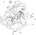
FIG. 2 is an exploded view of the eyeball imaging apparatus of FIG. 1 .
FIG. 3 is a diagram illustrating a method of measuring an EEG using the eyeball imaging apparatus of FIG. 1 .
FIG. 4 is a diagram illustrating a method of measuring an electrocardiogram and oxygen saturation using the eyeball imaging apparatus of FIG. 1 .
발명의 실시를 위한 최선의 형태Best mode for carrying out the invention
이하, 본 발명이 속하는 기술분야에서 통상의 지식을 가진 자가 본 발명의 기술적 사상을 용이하게 실시할 수 있을 정도로 상세히 설명하기 위하여, 본 발명의 가장 바람직한 실시예를 첨부 도면을 참조하여 설명하기로 한다. 우선 각 도면의 구성요소들에 참조부호를 부가함에 있어서, 동일한 구성요소들에 대해서는 비록 다른 도면상에 표시되더라도 가능한 한 동일한 부호를 가지도록 하고 있음에 유의해야 한다. 또한, 본 발명을 설명함에 있어, 관련된 공지 구성 또는 기능에 대한 구체적인 설명이 본 발명의 요지를 흐릴 수 있다고 판단되는 경우에는 그 상세한 설명은 생략한다.Hereinafter, in order to describe in detail enough that a person of ordinary skill in the art to which the present invention pertains can easily implement the technical idea of the present invention, the most preferred embodiment of the present invention will be described with reference to the accompanying drawings. . First, in adding reference numerals to the components of each drawing, it should be noted that the same components are given the same reference numerals as much as possible even though they are indicated on different drawings. In addition, in describing the present invention, if it is determined that a detailed description of a related known configuration or function may obscure the gist of the present invention, the detailed description thereof will be omitted.
이하, 본 발명의 실시예에 따른 안구촬영장치를 첨부된 도면을 참조하여 상세하게 설명하면 아래와 같다.Hereinafter, an eyeball photographing apparatus according to an embodiment of the present invention will be described in detail with reference to the accompanying drawings.
도 1은 본 발명의 실시예에 따른 안구촬영장치(10)를 설명하기 위한 도면이다.1 is a view for explaining an
본 발명의 일 실시예에 따른 안구촬영장치(10)는 피검사자의 안구를 촬영하여 안구 이미지를 생성하는 동시에 피검사자의 뇌파, 심전도 및 혈액 내 산소포화도 중 적어도 하나의 신체정보를 측정하도록 구성된 장치이며, 생성된 안구 이미지 및 신체정보를 통신망을 통하여 질병진단 전문가(전문의)에게 전송하도록 구성된 장치일 수 있다.The
도 1를 참조하면, 본 발명의 실시예에 따른 안구촬영장치(10)는 안구촬영장치(10)의 외관을 형성하는 본체(110), 본체(110)의 내부에 배치되어 피검사자의 안구를 촬영하도록 구성된 촬영부(120) 및 본체(110)의 외부에 배치되어 피검사자의 피부와 접촉되며, 피검사자의 안구를 촬영하는 동안 피검사자의 뇌파, 심전도 및 혈액 내 산소포화도 중 적어도 하나의 신체정보를 측정하도록 구성된 신체정보 수집부(130)를 포함한다. 도 2를 참조하여 안구촬영장치(10)를 더욱 상세하게 설명하도록 한다.Referring to FIG. 1 , an
도 2는 본 발명의 일 실시예에 따른 안구촬영장치(10)의 분해도이다.2 is an exploded view of the
도 2를 참조하면, 본체(110)는 안구촬영장치(10)의 외관을 형성하며, 내부에 중공이 형성되어 촬영부(120)를 수용할 수 있다. 본체(110)는 피검사자가 두손으로 안구촬영장치(10)를 잡고 안정적으로 안구를 촬영할 수 있도록 두손으로 용이하게 잡히는 크기와 모양으로 형성될 수 있다. 예를 들어, 도 1에 도시된 바와 같이, 모서리가 둥근 육각형의 형태로 구성될 수 있다. 본체(110)에는 촬영부(120)가 피검사자의 좌안 및 우안을 모두 촬영할 수 있도록 피검사자의 양안에 대응되는 위치에 렌즈가 형성될 수 있다. 이때, 렌즈는 본체(110) 내부에 배치되는 촬영부(120)를 보호하기 위한 커버 유리 또는 촬영부(120)로부터 제공되는 광을 집속하기 위한 광학 렌즈로 구성될 수 있다.Referring to FIG. 2 , the
한편, 촬영부(120)는 본체(110)의 내부에 배치되며, 피검사자의 좌안 또는 우안에 광을 조사하고 안구로부터 반사된 광을 검출하여 안구의 이미지를 획득할 수 있다. 구체적으로, 촬영부(120)는 광을 조사하는 광원, 반사된 광을 수집하는 광학부, 수집된 광을 통해 안구 이미지를 생성하는 이미지 생성부 및 광원, 광학부, 이미지 생성부의 위치를 조절하는 위치조절부 등으로 구성될 수 있다.On the other hand, the photographing
광원은 피검사자의 안구에 광을 조사할 수 있다. 광원을 통해 조사된 광은 각막, 수정체, 안구의 전방을 포함하는 전 구역 및 안구의 바닥을 포함하는 후 구역 등에 조사될 수 있다. 광원은 백색의 가시광선 영역대의 광을 조사할 수 있으며 640 nm에서 최대 효율을 갖는 백색 광원으로 구성될 수 있다. 또한, 광원은 안구의 각막 상의 특정 위치에 광을 조사할 수 있다. 광원은 적외선, 자외선 또는 가시광선 영역대의 광 중 적어도 하나를 조사할 수 있다. 그러나, 광원의 광이 이에 한정되는 것은 아니다.The light source may irradiate light to the eye of the subject. The light irradiated through the light source may be irradiated to the cornea, the lens, the anterior region including the front of the eyeball, and the posterior region including the bottom of the eyeball. The light source may be irradiated with white light in the visible ray region, and may be composed of a white light source having a maximum efficiency at 640 nm. In addition, the light source may irradiate light to a specific location on the cornea of the eyeball. The light source may irradiate at least one of infrared rays, ultraviolet rays, and visible light bands. However, the light of the light source is not limited thereto.
광학부는 안구에서 반사된 광을 수집할 수 있다. 광학부는 하나 이상의 렌즈, 편광 필터 및 광 스플리터 등을 구비할 수 있다. 광학부는 안구에서 반사된 광들의 이동 경로를 제어함으로써, 안구에서 반사된 광들이 이미지 생성부로 수집될 수 있다.The optics may collect light reflected from the eye. The optics may include one or more lenses, a polarizing filter, a light splitter, and the like. The optical unit controls a movement path of the light reflected from the eyeball, so that the light reflected from the eyeball may be collected by the image generator.
이미지 생성부는 광학부를 통과한 광을 센싱하여 안구 이미지를 생성할 수 있다. 예를 들어, 이미지 생성부는 광원을 통해 조사되어 안구에서 반사된 광을 센싱함으로써 안구 이미지를 생성할 수 있다.The image generator may generate an eye image by sensing the light passing through the optical unit. For example, the image generating unit may generate an eyeball image by sensing light reflected from the eye after being irradiated through a light source.
위치 조절부는 이미지 생성부에 의해 선명한 안구 이미지가 생성되도록 광원, 광학부 및 이미지 생성부의 위치를 조절하며, 광학부의 초점을 조절할 수 있다.The position adjusting unit may adjust positions of the light source, the optical unit, and the image generating unit so that a clear eye image is generated by the image generating unit, and may adjust the focus of the optical unit.
촬영부(120)의 위치 조절부는 피검사자의 좌안 및 우안 중 어느 하나를 촬영한 후, 나머지 하나의 촬영을 위해 촬영부(120)의 위치를 이동시킬 수 있다.The position adjusting unit of the photographing
한편, 촬영부(120)의 위치 조절부는 피검사자의 안구와 촬영부(120) 사이의 거리를 자동으로 조절함으로써, 피검사자가 숙련된 전문가의 도움 없이도, 용이하게 본인의 안구를 촬영하도록 할 수 있다. 예를 들어, 위치 조절부는 각막에서 반사된 광의 정보들로부터 각막과 촬영부(120) 사이의 거리를 예측하고, 그 거리가 레퍼런스 거리에 대응되도록 촬영부(120)의 위치를 제어할 수 있다.On the other hand, the position adjusting unit of the photographing
한편, 신체정보 수집부(130)는 본체(110) 외부에 배치되어 피검사자의 뇌파, 심전도 및 혈액 내 산소포화도 중 적어도 하나의 신체정보를 측정하도록 구성될 수 있다.Meanwhile, the body
도 2를 참조하면, 신체정보 수집부(130)는 뇌파 측정부(131), 심전도 측정부(132) 및 산소포화도 측정부(133) 중 적어도 하나를 포함할 수 있다. 비록, 도 2에는 신체정보 수집부(130)가 뇌파 측정부(131), 심전도 측정부(132) 및 산소포화도 측정부(133)를 모두 포함하는 것으로 도시되어 있으나, 신체정보 수집부(130)는 뇌파 측정부(131), 심전도 측정부(132) 및 산소포화도 측정부(133) 중 적어도 하나의 측정부만 포함할 수도 있다.Referring to FIG. 2 , the body
뇌파 측정부(131)는 피검사자의 뇌파를 측정할 수 있다. 여기서, 뇌파(EEG, electro-encephalography)는 뇌의 전기적인 활동을 머리 표면에 접촉된 전극(Electrode)에 의해 비침습적으로 측정한 전기신호이다. 뇌파(EEG, electro-encephalography)는 신경계와 뇌신경 사이에 신호가 발생할 때 생기는 미세한 생체 전기로써, 뇌 표면에서 발생하는 전기 포텐셜 차이를 전극을 사용하여 측정한다. 뇌파 신호는 델타(δ)파, 쎄타(θ)파, 알파(α)파, 베타(β)파 및 감마(γ)파로 분류된 주파수 분석을 통해 스펙트럼으로 볼 수 있다. 뇌파에 반영되는 뇌의 전기적 활동은 신경세포(neurons), 교세포(glia cells), 혈뇌장벽(blood-brain barrier)에 의해 결정되는데 주로 신경세포에 의해 발생된다.The
뇌파 측정부(131)는 좌뇌 및 우뇌에서 발생된 뇌파 전위를 전극을 이용하여 머리 표면의 전위차를 측정한다. 이때, 전극을 통해 수신된 뇌파 신호는 준위가 낮기 때문에 직접적인 이용이 용이하지 않다. 이에 따라, 뇌파 측정부(131)는 전극에서 출력되는 신호를 증폭시키고 증폭된 신호를 디지털 신호로 변환함으로써, 뇌의 상태를 측정할 수 있다.The
본 발명에 사용되는 뇌파 측정은 비침습적인 전기신호를 이용할 수 있다. 그러나, 이에 한정되는 것은 아니다. 일반적으로 비침습적인 방법을 이용하여 뇌파를 측정하는 경우, 헬멧 또는 헤드셋 형태의 장비로 뇌파를 측정할 수 있으며, 통상 머리 표면에 해당되는 부위에 전극을 장착한다.EEG measurement used in the present invention may use a non-invasive electrical signal. However, the present invention is not limited thereto. In general, when measuring EEG using a non-invasive method, EEG can be measured with a helmet or headset type equipment, and electrodes are usually mounted on a portion corresponding to the surface of the head.
본 발명에 따른 뇌파 측정부(131)는 피검사자의 눈썹 위의 피부에 접촉되도록 구성되어 피검사자가 안구를 촬영하는 동안 자연스럽게 뇌파를 측정할 수 있도록 구성된다.The
예를 들어, 본 발명에 따른 뇌파 측정부(131)는 안구촬영장치(10)의 접촉부(140)에 배치된다. 구체적으로, 머리의 두피에 뇌파 전극을 접촉시켜 뇌파를 측정하는 것은 숙련자가 전극과 두피를 전기적으로 연결해주어야 가능하기 때문에 피검사자가 혼자 측정하기 어렵고 준비 시간이 오래 소요될 수 있다. 본 발명에 따른 뇌파 측정부(131)는 접촉부(140)의 수납홈(141)을 통해 뇌파 전극을 삽입하여 피검사자의 눈썹 위의 피부에 뇌파 전극을 접촉시킴으로써, 피검사자의 고통없이 간편하게 뇌파를 직접 측정할 수 있다.For example, the
접촉부(140)는 피검사자가 안구촬영장치(10)를 착용하는 경우, 피검사자의 안면에 접촉되는 부분일 수 있다. 접촉부(140)는 피검사자의 안면의 굴곡에 대응하는 구조를 가질 수 있다. 또한, 접촉부(140)는 피검사자의 안면과 안정적으로 밀착되며, 피검사자의 양안에 외부광을 효과적으로 차광하기 위하여 검은색 계열의 탄성 재질(고무, 실리콘 등)로 형성될 수 있다. 접촉부(140)에는 일부 영역에 피검사자의 코가 삽입될 수 있는 형상을 갖는 홈이 형성될 수 있다. 접촉부(140)는 안구 촬영 중에 피검사자의 양안에 암실을 제공할 수 있어 동공 반사를 최소화할 수 있다. 이를 통해, 본 발명에 따른 안구촬영장치(10)는 피검사자의 안구 이미지를 정확히 촬영할 수 있다.The
뇌파 측정부(131)는 피검사자의 눈 주변의 안면에 접촉되는 접촉부(140)에 위치되고, 피검사자가 안구촬영장치(10)를 통해 안구를 촬영하는 동안 자연스럽게 눈썹 위의 피부가 뇌파 측정부(131)에 접촉되도록 구성될 수 있다.The
뇌파 측정부(131)는 본체(110)의 내부에 배치되는 뇌파 측정 모듈(131a) 및 피검사자의 눈썹 위의 피부에 접촉하는 적어도 하나의 뇌파 측정 전극(131b)을 포함할 수 있다. 여기서, 피검사자의 눈썹 위의 피부에 접촉하는 뇌파 측정 전극(131b)은 피검사자의 피부에 흐르는 전기신호를 감지할 수 있다. 이후, 뇌파 측정 모듈(131a)은 뇌파 측정 전극(131b)에서 감지된 전기신호를 증폭 및 처리하여 뇌파 신호를 생성하고 생성된 뇌파 신호를 수집할 수 있다.The
접촉부(140)는 뇌파 측정부(131)의 뇌파 측정 전극(131b)이 삽입되는 수납홈(141)을 포함할 수 있다. 뇌파 측정부(131)의 일면은 접촉부(140)의 일면보다 본체(110)의 내부 방향으로 함몰되어 배치되며, 피검사자의 안면에 의해 접촉부(140)의 일면이 압축되는 경우, 뇌파 측정부(131)의 일면은 접촉부(140)의 일면 상으로 노출될 수 있다.The
수납홈(141)은 접촉부(140)의 내측면 둘레에 형성되어 뇌파 측정부(131)의 뇌파 측정 전극(131b)이 삽입되는 입구로 기능할 수 있다. 예를 들어, 수납홈(141)은 뇌파 측정 전극(131b)의 밑면 형상에 대응되도록 원 형상으로 형성될 수 있으나 이에 제한되지 않는다.The receiving
수납홈(141)은 뇌파 측정 전극(131b)의 일단부 측이 삽입되어 걸리도록 형성될 수 있다. 이때, 수납홈(141)에 삽입된 뇌파 측정 전극(131b)은 피검사자의 안면과 대향되는 방향으로 수납홈(141) 입구에 돌출되지 않도록 할 수 있다. 이 경우, 뇌파 측정 전극(131b)은 뇌파 측정 전극(131b)의 일면에 이물질 등이 묻어 뇌파 측정부(131)가 오작동 되는 것을 억제시킬 수 있다. 피검사자가 안구를 촬영하는 동안은 피검사자의 안면에 의해 접촉부(140)가 압축되어 피검사자의 안면과 접촉부(140)의 뇌파 측정 전극(131b)의 일면이 서로 가까워진다. 접촉부(140) 가 충분히 압축되는 경우, 수납홈(141) 입구로 뇌파 측정 전극(131b)이 자연스럽게 노출되어 피검사자의 눈썹 위 피부에 접촉된다. 이 경우, 뇌파 측정 전극(131b)은 뇌파 측정 전극(131b) 외에 다른 물체가 접촉되는 것을 방지할 수 있고, 피검사자의 뇌파를 정확하게 측정할 수 있다.The receiving
또한, 뇌파 측정 전극(131b)은 고무 재질의 접촉부(140)에 비해 단단한 금속 재질로 구성되므로, 피검사자가 안구를 촬영하는 동안 피검사자의 피부에 접촉되어 마찰력을 증대시킨다. 이에, 연질의 접촉부(140)가 슬립(slip)되는 것이 최소화될 수 있으며, 이를 통해 안구촬영장치(10)의 위치가 안정적으로 고정될 수 있다.In addition, since the EEG measuring electrode 131b is made of a metal material that is harder than the
한편, 신체정보 수집부(130)는 피검사자의 엄지에 접촉되어 피검사자의 심전도를 측정하도록 구성된 심전도 측정부(132)를 더 포함할 수 있다.Meanwhile, the body
심전도 측정부(132)는 피검사자의 심전도를 측정할 수 있다. 여기서, 심전도(ECG, electrodardiogram)는 심장근육의 수축 확장에 따른 활동 전류를 외부에서 전극을 부착하여 측정 및 기록한 것이다. 심장근육이 수축 이완할 때 발생되는 활동전위는 심장으로부터 온 몸으로 퍼지는 전류를 일으키고 이 전류는 몸의 위치에 따라 전위차를 발생시키는데, 이 전위차는 인체의 피부에 부착된 표면전극(surface electrode)을 통해 검출하여 기록할 수 있다. 이와 같은 심전도는 심장의 이상유무 확인에 이용되며, 협심증, 심근경색, 부정맥 등 심장질환계의 질환을 측정하는 데에는 기본적인 방법으로 이용된다. 심전도 측정에는 수직모드(vertical mode)와 수평 모드(horizontal mode)가 있다.The
본 발명에 사용되는 심전도 측정은 수직모드(vertical mode)일 수 있다. 그러나, 이에 한정되는 것은 아니다. 일반적으로 수직 모드의 측정인 경우, 어느 신체에 전극을 부착하여도 상관없으며, 통상 양쪽 손목과 왼쪽 발목에 전극을 장착할 수 있고, 손목 또는 발목이 아니라 몸체 가까이에 전극을 둘 수도 있고, 좀 더 심장으로부터 먼 쪽, 예를 들면 손가락이나 발가락 끝 등에 전극을 두더라도 동일한 결과를 얻을 수 있다. 본 발명에 따른 심전도 측정부(132)는 피검사자의 손가락 중 엄지를 사용하여 심전도를 측정할 수 있다.The ECG measurement used in the present invention may be in a vertical mode. However, the present invention is not limited thereto. In general, in the case of vertical mode measurement, it does not matter whether electrodes are attached to any body, in general, electrodes can be mounted on both wrists and left ankles, and electrodes can be placed near the body rather than on the wrist or ankle, and more The same result can be achieved by placing electrodes on the far side from the heart, for example on the tip of a finger or toe. The
본 발명에 따른 심전도 측정부(132)는 본체(110) 중 피검사자의 안면에 대향되는 일면의 양측에 위치될 수 있다. 예를 들어, 심전도 측정부(132)는 피검사자가 안구를 촬영하기 위해 안구촬영장치(10)를 양손으로 들 때 양손의 엄지가 접촉되는 부분에 위치될 수 있다. 심전도 측정부(132)는 피검사자의 오른쪽 엄지와 접촉하는 부분과 피검사자의 왼쪽 엄지와 접촉하는 부분에 각각 이격되어 위치될 수 있다.The
심전도 측정부(132)는 전극을 구비할 수 있다. 심전도 측정부(132)에 구비된 전극은 피검사자의 엄지에 접촉된다. 이 상태에서, 피검사자가 안구촬영장치(10)를 작동시키면, 심전도 측정부(132)도 함께 작동될 수 있다. 이때, 심전도 측정부(132)에 구비된 측정센서가 피검사자의 엄지를 통해 전달되는 전류를 전극을 통해 감지함으로써, 피검사자의 심전도를 측정하고 정보를 수집할 수 있다.The
또한, 피검사자의 엄지와 접촉되는 심전도 측정부(132) 접촉 부분은 단단한 금속 재질로 구성되므로, 피검사자가 심전도를 측정하는 동안 피검사자의 엄지에 접촉되어 마찰력을 증대시킨다.In addition, since the contact portion of the
상술한 바와 같이, 심전도 측정부(132)는 피검사자가 안구촬영장치(10)를 잡을 때 피검사자의 엄지가 위치하는 부분에 위치된다. 이 경우, 피검사자는 특별한 노력없이 안구 이미지를 촬영하는 동안 자연스럽게 심전도를 측정할 수 있다. 특히, 피검사자는 안구 촬영동안 안구촬영장치(10)를 안정적으로 지지하기 위해 손가락을 안구촬영장치(10)에 밀착시킬 것이므로, 심전도 측정부(132)의 전극과 피검사자의 엄지는 안정적으로 접촉될 수 있다. 이에, 피검사자의 심전도는 더욱 안정적으로 측정될 수 있다.As described above, the
한편, 신체정보 수집부(130)는 피검사자의 손가락에 접촉되어 피검사자의 산소포화도를 측정하도록 구성된 산소포화도 측정부(133)를 더 포함할 수 있다.Meanwhile, the body
산소포화도 측정부(133)는 피검사자의 산소포화도를 측정할 수 있다. 여기서, 산소포화도는 혈액내 산소와 결합한 헤모글로빈의 양이 전체 헤모글로빈의 양에서 차지하는 비율을 백분율로 수치화한 지표이다. 즉, 산소포화도를 측정함으로써, 적혈구에 의해 운반되는 산소의 양으로 얼마나 효과적으로 호흡하고 있는지, 산소가 전신에 잘 전달되고 있는지 등을 알아볼 수 있다.The oxygen
본 발명에 사용되는 산소포화도 측정은 혈중산소포화도(SPO2, saturation of partial pressure oxygen)를 측정하는 센서를 이용하여 피검사자의 산소포화도를 측정할 수 있다. 혈중 산소포화도 센서를 이용한 산소포화도 측정은 심장의 수축과 이완으로 변화하는 혈액 용적과 혈액 내의 헤모글로빈에 흡수되는 빛의 양의 선형적 관계를 이용하여 신호를 획득하는 방법이다. 예를 들어, 생체에 투과성 빔을 사용하여 적외선 광도변화를 측정하는 방법으로 측정될 수 있다. 일반적으로 산소포화도 측정은 손목, 손가락, 발가락, 귓볼 등에서 측정할 수 있다. 그러나, 이에 한정되는 것은 아니다.The oxygen saturation measurement used in the present invention may measure the oxygen saturation of a subject by using a sensor that measures blood oxygen saturation (SPO2). Oxygen saturation measurement using a blood oxygen saturation sensor is a method of acquiring a signal using a linear relationship between the volume of blood that changes due to contraction and relaxation of the heart and the amount of light absorbed by hemoglobin in the blood. For example, it can be measured by a method of measuring infrared luminous intensity change using a beam that is transparent to a living body. In general, oxygen saturation can be measured on wrists, fingers, toes, and earlobes. However, the present invention is not limited thereto.
본 발명에 따른 산소포화도 측정부(133)는 피검사자의 손가락으로부터 산소포화도를 측정할 수 있다. 예를 들어, 산소포화도 측정부(133)는 피검사자가 안구를 촬영하기 위해 안구촬영장치(10)를 양손으로 들 때, 양손의 손가락 중 하나의 손가락이 접촉되는 부분에 배치될 수 있다. 산소포화도 측정부(133)는 피검사자의 오른쪽 손가락 중 하나의 손가락과 접촉하는 부분과 피검사자의 왼쪽 손가락 중 하나의 손가락과 접촉하는 부분에 각각 이격되어 배치될 수 있다.The oxygen
본 발명에 따른 산소포화도 측정부(133)는 본체(110)와 일체형으로 양측에 위치하고, 산소포화도 측정부(133)가 본체(110)의 내측으로 함몰되어 피검사자의 손가락을 인입시킬 수 있다. 예를 들어, 산소포화도 측정부(133)의 함몰된 홈의 형상은 인입된 피검사자의 손가락이 고정되도록 소정의 깊이로 함몰된 반타원 형상일 수 있다. 그러나, 이에 한정되는 것은 아니다.The oxygen
본 발명에 따른 산소포화도 측정부(133)는 피검사자의 손가락의 상부와 하부에 동시에 접촉되도록 집게 형태로 구성될 수 있다. 예를 들어, 집게 형태의 산소포화도 측정부(133)가 손가락의 상부와 하부에 동시에 접촉되는 경우, 집게 형태의 산소포화도 측정부(133)는 피검사자의 손가락에 압박을 주지 않도록 탄성 재질(실리콘 또는 고무)로 구성될 수 있다. 또한, 집게 형태의 산소포화도 측정부(133)는 산소포화도를 측정하는 동안에는 집게의 내측면에 손가락의 상부와 하부가 접촉되도록 탄성 소재인 스프링을 이용할 수 있으나, 이에 한정되는 것은 아니다.The oxygen
집게 형태의 산소포화도 측정부(133)는 산소포화도를 측정할 수 있는 센서가 형성될 수 있다. 여기서, 센서는 적외선과 적색광의 흡수도 차이를 활용하기 위해 적외선과 적색의 광원이 함께 사용될 수 있다. 본체(110)의 내측으로 함몰된 산소포화도 측정부(133)에 피검사자의 손가락을 인입시킴으로써, 산소포화도 측정부(133)의 내부가 외부의 빛으로부터 차단되어 센서는 외부 빛에 의한 간섭없이 피검사자의 손가락을 통과하는 광원의 양을 산소포화도 측정부(133)에 전달할 수 있다. 이를 통해, 본 발명에 따른 산소포화도 측정부(133)는 피검사자의 산소포화도 측정의 정확성 및 신뢰성이 향상될 수 있다.The oxygen
또한, 산소포화도 측정부(133)가 본체(110)의 내측으로 함몰되어 피검사자의 손가락을 인입시키는 구조로 구성되어 있으므로, 피검사자가 안구촬영장치(10)를 흔들리지 않고 좀 더 안정적으로 그립(grip)할 수 있도록 한다.In addition, since the oxygen
한편, 안구촬영장치(10)는 피검사자의 안구 촬영 및 신체정보 수집이 완료되거나, 안구 촬영 및 신체정보 수집과정에 오류가 존재하는 경우 경보를 발생시키는 경보부(150)를 더 포함할 수 있다. 예를 들어, 피검사자가 안구의 촬영 및 신체정보 수집이 완료되지 않은 상태에서 안구촬영장치(10)에 접촉되어 있는 신체 중 하나라도 접촉 위치에서 벗어나는 경우, 경보부(150)를 통해 경보가 발생될 수 있다. 또한, 피검사자의 안구 촬영 및 신체정보 수집이 완료되는 경우에도 경보부(150)를 통해 경보가 발생될 수 있다.On the other hand, the
경보부(150)는 피검사자의 안구 촬영 및 신체정보 수집의 진행 상황 정보를 피검사자에게 알려줄 수 있다. 구체적으로, 피검사자가 알맞은 위치에서 안구의 촬영 및 신체정보 수집을 진행할 수 있도록 경보부(150)를 통해 안구 및 신체정보의 접촉 위치를 알려줄 수 있다. 또한, 피검사자의 안구의 촬영 및 신체정보 수집이 진행되는 동안 피검사자에게 진행상황을 알려줄 수 있다. 예를 들면, 피검사자가 안구 촬영 및 뇌파 측정을 진행하고 있는 경우, 경보부(150)는 “현재 뇌파를 측정 중이니 뇌파 측정부에 안면을 접촉한 상태를 유지하십시오.”라는 안내를 알려줄 수 있다. 또한, 피검사자가 안구 촬영 및 심전도 측정을 진행하고 있는 경우, 경보부(150)는 “현재 심전도를 측정 중이니 심전도 측정부에서 엄지를 분리하지 마십시오.”라는 안내를 알려줄 수 있다. 또한, 피검사자가 안구 촬영 및 산소포화도 측정을 진행하고 있는 경우, 경보부(150)는 “현재 산소포화도를 측정 중이니 산소포화도 측정부에서 손가락을 분리하지 마십시오.”라는 안내를 알려줄 수 있다.The
경보부(150)는 안구촬영장치(10)의 본체(110) 중 피검사자의 안면에 대향되는 일면의 양측에 위치할 수 있다. 경보부(150)는 피검사자가 안구 촬영 중에도 안구 촬영 및 신체정보 수집의 완료여부 또는 안구 촬영 및 신체정보 수집의 오류 발생여부를 용이하게 알 수 있도록 청각 및 촉각 신호를 발생시키도록 구성될 수 있다. 예를 들어, 경보부(150)는 청각 신호를 발생시키는 스피커 또는 촉각 신호를 발생시키는 진동 모터 등으로 구성될 수 있다.The
구체적으로, 안구촬영장치(10)에 경보부(150)가 구비되지 않는 경우, 피검사자는 안구 촬영 및 신체정보 수집이 완료되었는지 아닌지를 알 수 없다. 이 경우, 피검사자는 안구 촬영 및 신체정보 수집이 완료되지 않은 상태에서 안구촬영장치(10)를 신체로부터 분리할 수 있다. 이에 따라, 피검사자는 온전한 안구 이미지 및 신체정보를 수집할 수 없게 된다. 반면에, 안구촬영장치(10)에 경보부(150)가 구비되는 경우, 피검사자는 안구 촬영 및 신체정보 수집이 완료되었는지 아닌지를 알 수 있다. 이 경우, 피검사자는 안구 촬영 및 신체정보 수집이 완료될 때까지 신체를 안구촬영장치(10)로부터 분리시키지 않을 수 있다. 이에 따라, 피검사자는 온전한 안구 이미지 및 신체정보를 수집할 수 있다. 결과적으로, 본 발명에 따른 안구촬영장치(10)는 경보부(150)를 더 포함함으로써, 피검사자가 안구를 촬영하고 다양한 신체정보를 수집하는데 있어서 숙련된 전문가의 도움을 배제시킬 수 있고, 정확한 안구의 촬영 및 다양한 신체정보를 수집할 수 있다.Specifically, when the
한편, 본 발명에 따른 안구촬영장치(10)는 피검사자의 안구 촬영 및 신체정보 수집이 완료되는 경우, 촬영된 안구 이미지 및 측정된 신체정보에 관한 데이터를 외부로 전송하도록 구성된 통신부를 더 포함할 수 있다. 구체적으로, 통신부는 BT(BlieTooth), Zigbee, WiFi(Wireless Fidelity), IR(Infrared), Serial Interface, USB(Universal Serial Bus), NFC(near Field Communication) 등과 같은 다양한 통신 방식을 통해 안구촬영장치(10)와 통신을 수행할 수 있다.On the other hand, the
통신부는 안구촬영장치(10)를 비롯한 각종 외부 장치 및 서버와 통신을 수행할 수 있다. 특히, 통신부는 안구촬영장치(10)로부터 수집된 피검사자에 대한 데이터들을 외부 장치 및 서버로 전송할 수 있다. 여기서 외부 장치는, 스마트폰, 태블릿 PC, PC, 스마트 TV, 휴대폰, PDA(personal digital assistant), 랩톱, 디지털 카메라, 웨어러블 기기, 전자 칠판, 터치 테이블 및 기타 모바일 또는 비모바일 컴퓨팅 장치 등으로 구현될 수 있다. 그러나, 이에 제한되는 것은 아니다.The communication unit may communicate with various external devices and servers, including the
이에 따라, 안구촬영장치(10)는 통신부를 통해 피검사자가 촬영한 안구 이미지 및 측정한 신체정보에 관한 데이터를 질병진단 전문가에게 전송할 수 있고, 질병진단 전문가는 피검사자의 데이터를 확인하여 진단할 수 있다. 통신부는 질병진단 전문가에게로의 전송뿐 아니라, 의료 기관 내의 서버나 의료 연구를 위한 데이터베이스로 전송할 수 있다. 이 경우, 의료 기관 또는 의료 연구기관에 전송된 피검사자의 데이터들은 의료 연구의 목적으로 활용될 수 있다.Accordingly, the
본 발명에 따른 안구촬영장치(10)는 통신부를 더 포함함으로써, 피검사자가 촬영한 안구 이미지 및 수집한 신체정보를 의료기관에 직접 방문하지 않아도 질병진단 전문가에게 전송할 수 있으므로 신속한 진단이 이루어져 질병을 조기에 발견할 수 있다.The
발명의 실시를 위한 형태Modes for carrying out the invention
도 3 및 도 4를 참조하여, 본 발명의 일 실시예에 따른 안구촬영장치(10)를 이용하여 신제정보를 수집하는 방법을 구체적으로 설명한다.3 and 4, a method of collecting new information using the
도 3은 도 1의 안구촬영장치(10)를 이용하여 뇌파를 측정하는 방법을 나타낸 도면이고, 도 4는 도 1의 안구촬영장치(10)를 이용하여 심전도 및 산소포화도를 측정하는 방법을 나타낸 도면이다.3 is a view showing a method of measuring EEG using the
도 3 및 도 4를 참조하면, 피검사자는 두손으로 안구촬영장치(10)를 잡고 안구를 촬영할 수 있도록 피검사자의 눈 주변의 안면을 안구촬영장치(10)의 접촉부(140)에 접촉시킨다. 피검사자가 안구촬영장치(10)의 접촉부(140)에 피검사자의 눈 주변의 안면을 접촉시키면, 안구촬영장치(10)는 피검사자의 안구 촬영을 시작한다. 동시에, 안구촬영장치(10)는 접촉부(140)의 수납홈(141)에 삽입되어 있는 뇌파 측정부(131)를 통해 피검사자의 뇌파를 측정할 수 있다.Referring to FIGS. 3 and 4 , the subject holds the
이때, 피검사자의 두손은 자유롭게 안구촬영장치(10)를 잡을 수 있다. 예를 들어, 피검사자가 안구 촬영 및 뇌파 측정만을 하는 경우에는 피검사자는 두손의 손가락을 심전도 측정부(132) 및 산소포화도 측정부(133)에 위치하지 않아도 무방하다.In this case, both hands of the subject can freely hold the
만약, 피검사자가 안구 촬영 및 뇌파 측정 이외에도 심전도 또는 산소포화도를 측정하는 경우에는 피검사자는 안구촬영장치(10)를 잡은 두손에서 양 엄지를 심전도 측정부(132)에 접촉시키거나, 양 손가락 중 각각 하나를 양측의 산소포화도 측정부(133)에 인입시킴으로써 심전도 또는 산소포화도에 해당하는 신체정보를 측정할 수 있다. 이때, 안구촬영장치(10)는 피검사자의 안구를 촬영하여 안구 이미지를 생성하는 동시에 피검사자의 뇌파, 심전도 및 혈액 내 산소포화도를 모두 측정할 수 있다.If the subject measures the electrocardiogram or oxygen saturation in addition to the eye photographing and EEG measurement, the examinee touches both thumbs to the
본 발명에 따른 안구촬영장치(10)는 신체정보 수집부(130)를 포함함으로써, 안구에 대한 질병뿐 아니라 다른 질병에 대한 진단을 할 수 있다. 즉, 신체정보 수집부(130)는 뇌파, 심전도 및 혈액 내의 산소포화도를 측정하여 수집된 신체정보를 통해 안구 질병과 관련된 질병 및 다양한 질환을 진단할 수 있다.The
예를 들어, 알츠하이머는 안구 이미지를 통해 안구의 망막이 얇아지고 안구 후면의 혈관이 소실되는 증상을 확인함으로써 발병의 지표가 될 수 있다. 또한, 알츠하이머는 측정된 뇌파의 정보를 통해 알츠하이머를 앓고 있는 환자들의 뇌파 정보와 비교함으로써 발병의 여부가 정해질 수 있다. 따라서, 피검사자가 안구촬영장치(10)를 통해 안구를 촬영하고 뇌파를 측정하는 경우, 안구촬영장치(10)는 안구 이미지와 뇌파 정보를 통해 알츠하이머를 진단할 수 있다.For example, Alzheimer's can be an indicator of the onset of Alzheimer's by identifying the symptoms of thinning of the retina of the eye and loss of blood vessels at the back of the eye through eye images. In addition, the onset of Alzheimer's may be determined by comparing the measured EEG information with EEG information of patients suffering from Alzheimer's disease. Accordingly, when the examinee photographs the eyeball through the
또한, 안구의 망막에는 망막에 피를 공급해주는 혈관인 망막 동맥과 망막에서 사용한 피를 다시 심장으로 보내는 혈관인 망막 정맥, 그리고 망막 동맥과 망막 정맥에서 갈라져 나온 혈관인 분지들이 있다. 본 발명에 따른 안구촬영장치(10)는 촬영된 안구 이미지를 통해 망막 동맥, 망막 정맥 및 분지들이 막히는 형태를 확인할 수 있다. 한편, 피검사자가 안구촬영장치(10)를 통해 안구를 촬영하고 심전도 또는 산소포화도를 측정하는 경우, 안구 이미지 외에 심전도 또는 혈관의 산소포화도 정보를 취득할 수 있으므로, 안구 이미지와 심전도 및 혈관의 산소포화도 정보를 종합적으로 분석함으로써, 심혈관질환, 고혈압, 당뇨 등의 질병을 진단할 수 있다.Also, in the retina of the eye, there are the retinal artery, which is a blood vessel that supplies the retina, the retinal vein, which is a blood vessel that sends the blood used in the retina back to the heart, and branches, which are blood vessels that branch off from the retinal artery and the retinal vein. The
본 발명에 따른 안구촬영장치(10)는 피검사자가 숙련된 전문가의 도움 없이 손쉽게 안구를 촬영하고 신체정보를 측정할 수 있으며, 측정된 데이터들을 통신망을 통하여 질병진단 전문가에게 전송함으로써 질병을 신속하게 조기 발견할 수 있다.The
본 발명에 따른 안구촬영장치(10)는 통신부를 통해 외부 데이터베이스와 연결된다. 피검사자의 의료데이터가 데이터베이스에 축적 저장되고, 데이터베이스에 저장된 데이터들은 의료 기술 개발의 자료로 사용될 수 있다.The
나아가, 본 발명에 따른 안구촬영장치(10)는 통신부를 통해 의료 시설이 낙후된 지역 환자들의 의료데이터를 실시간으로 외부 장치 및 서버에 전송할 수 있고, 원격 진단을 가능하게 할 수 있다. 이에 따라, 낙후된 의료 환경을 개선하는데 도움이 될 수 있다.Furthermore, the
전술한 본 발명의 설명은 예시를 위한 것이며, 본 발명이 속하는 기술분야의 통상의 지식을 가진 자는 본 발명의 기술적 사상이나 필수적인 특징을 변경하지 않고서 다른 구체적인 형태로 쉽게 변형이 가능하다는 것을 이해할 수 있을 것이다. 그러므로 이상에서 기술한 실시예들은 모든 면에서 예시적인 것이며 한정적이 아닌 것으로 이해해야만 한다. 예를 들어, 단일형으로 설명되어 있는 각 구성 요소는 분산되어 실시될 수도 있으며, 마찬가지로 분산된 것으로 설명되어 있는 구성 요소들도 결합된 형태로 실시될 수 있다.The above description of the present invention is for illustration, and those of ordinary skill in the art to which the present invention pertains can understand that it can be easily modified into other specific forms without changing the technical spirit or essential features of the present invention. will be. Therefore, it should be understood that the embodiments described above are illustrative in all respects and not restrictive. For example, each component described as a single type may be implemented in a dispersed form, and likewise components described as distributed may be implemented in a combined form.
본 발명의 범위는 상기 상세한 설명보다는 후술하는 특허청구범위에 의하여 나타내어지며, 특허청구범위의 의미 및 범위 그리고 그 균등 개념으로부터 도출되는 모든 변경 또는 변형된 형태가 본 발명의 범위에 포함되는 것으로 해석되어야 한다.The scope of the present invention is indicated by the following claims rather than the above detailed description, and all changes or modifications derived from the meaning and scope of the claims and their equivalent concepts should be interpreted as being included in the scope of the present invention. do.
본 발명에 따른 안구촬영장치(10)는 의료산업에 사용될 수 있다. 구체적으로, 의료서비스가 낙후된 국가나 지역에서 안구촬영장치(10)의 사용자가 직접 안구 이미지를 촬영하고, 신체정보를 측정하여 수집한 데이터를 외부 서버 및 장치에 전송한다. 이때, 외부의 의료기관 및 전문가들은 전송된 데이터를 모니터링 할 수 있다. 따라서, 안구촬영장치(10)는 원격의료 산업에 널리 적용될 수 있다.The
Claims (11)
Translated fromKorean상기 본체 내부에 배치되어 피검사자의 안구를 촬영하도록 구성된 촬영부;및
상기 본체 외부에 배치되어 상기 피검사자의 피부와 접촉되며, 상기 피검사자의 안구를 촬영하는 동안 상기 피검사자의 뇌파, 심전도 및 혈액 내 산소포화도 중 적어도 하나의 신체정보를 측정하도록 구성된 신체정보 수집부를 포함하고,
상기 신체정보 수집부는 상기 피검사자의 눈 주변의 안면에 접촉되는 접촉부에 위치되고,
상기 피검사자의 눈썹 위의 피부에 접촉되어 상기 피검사자의 뇌파를 측정하도록 구성된 뇌파 측정부를 포함하고,
상기 접촉부는 상기 뇌파 측정부가 삽입되는 수납홈을 포함하고,
상기 뇌파 측정부의 일면은 상기 접촉부의 일면보다 상기 본체의 내부 방향으로 함몰되어 배치되어, 상기 피검사자가 상기 안구촬영장치를 사용하지 않을 경우, 상기 뇌파 측정부가 외부로 노출되지 않으며, 상기 피검사자의 안면에 의해 상기 접촉부의 상기 일면이 압축되는 경우, 상기 뇌파 측정부의 상기 일면은 상기 접촉부의 상기 일면 상으로 노출되어, 상기 피검사자의 안면이 상기 접촉부에 압축되어 상기 뇌파 측정부가 뇌파를 측정하는 동안 상기 피검사자의 양안에 암실을 제공하는 것을 특징으로 하는,
안구촬영장치.a body forming the exterior of the eye-capturing apparatus;
A photographing unit disposed inside the body and configured to photograph the eye of the subject; and
It is disposed outside the main body, is in contact with the subject's skin, and includes a body information collecting unit configured to measure at least one of the subject's brain waves, electrocardiogram, and oxygen saturation in blood while photographing the subject's eyeballs,
The body information collection unit is located in a contact portion that comes into contact with the face around the eyes of the subject,
and an EEG measuring unit configured to contact the skin on the eyebrow of the subject to measure the EEG of the subject,
The contact part includes a receiving groove into which the EEG measuring part is inserted,
One surface of the EEG measuring part is disposed to be recessed in the inner direction of the main body rather than the one surface of the contact part, and when the subject does not use the eyeball imaging device, the EEG measuring unit is not exposed to the outside, and the face of the subject is not exposed. When the one surface of the contact part is compressed by the Characterized in providing a darkroom in both eyes,
eye imaging device.
상기 신체정보 수집부는 상기 피검사자의 엄지에 접촉되어 상기 피검사자의 심전도를 측정하도록 구성된 심전도 측정부를 더 포함하는, 안구촬영장치.According to claim 1,
The body information collecting unit further comprises an electrocardiogram measuring unit configured to contact the subject's thumb to measure the subject's electrocardiogram.
상기 심전도 측정부는 상기 본체 중 상기 피검사자의 안면에 대향되는 일면의 양측에 위치하는, 안구촬영장치.5. The method of claim 4,
The electrocardiogram measuring unit is located on both sides of one side of the body opposite to the face of the examinee, an eye photographing apparatus.
상기 신체정보 수집부는 상기 피검사자의 손가락에 접촉되어 상기 피검사자의 산소포화도를 측정하도록 구성된 산소포화도 측정부를 더 포함하는, 안구촬영장치.According to claim 1,
The body information collecting unit further includes an oxygen saturation measuring unit configured to contact the subject's finger to measure the subject's oxygen saturation level.
상기 산소포화도 측정부는 상기 본체와 일체형으로 양측에 위치하고, 상기 산소포화도 측정부가 상기 본체의 내측으로 함몰되어 상기 피검사자의 손가락을 인입시키는, 안구촬영장치.7. The method of claim 6,
The oxygen saturation measuring unit is integrally located on both sides of the main body, and the oxygen saturation measuring unit is recessed inside the main body to insert a finger of the subject.
상기 산소포화도 측정부는 상기 피검사자의 손가락의 상부와 하부에 동시에 접촉되도록 집게 형태로 구성되는, 안구촬영장치.8. The method of claim 7,
The oxygen saturation measuring unit is configured in the form of a forceps so as to contact the upper and lower portions of the finger of the subject at the same time.
상기 촬영부는 상기 피검사자의 좌안 및 우안 중 어느 하나를 촬영한 후 나머지 하나의 촬영을 위해 상기 촬영부의 위치가 이동되도록 구성되는, 안구촬영장치.According to claim 1,
The photographing unit is configured to move the position of the photographing unit for photographing the other one after photographing any one of the left eye and the right eye of the subject.
상기 피검사자의 안구 촬영 및 신체정보 수집이 완료되거나, 안구 촬영 및 신체정보 수집과정에 오류가 존재하는 경우 경보를 발생시키는 경보부를 더 포함하고,
상기 경보부는 상기 피검사자의 안구 촬영 및 신체정보 수집의 진행 상황 정보를 상기 피검사자에게 알려주는, 안구촬영장치.According to claim 1,
Further comprising an alarm unit that generates an alarm when the eye photographing and body information collection of the subject is completed or there is an error in the eye photographing and body information collection process,
The alarm unit informs the examinee of progress status information of the subject's eye photographing and body information collection, an eye photographing apparatus.
상기 피검사자의 안구 촬영 및 신체정보 수집이 완료되는 경우, 촬영된 안구 이미지 및 측정된 신체정보에 관한 데이터를 외부 장치로 전송하도록 구성된 통신부를 더 포함하는, 안구촬영장치.According to claim 1,
and a communication unit configured to transmit the captured eye image and measured body information data to an external device when the eye photographing and body information collection of the subject are completed.
Applications Claiming Priority (1)
| Application Number | Priority Date | Filing Date | Title |
|---|---|---|---|
| PCT/KR2019/004279WO2020209401A1 (en) | 2019-04-10 | 2019-04-10 | Eye imaging apparatus |
Publications (2)
| Publication Number | Publication Date |
|---|---|
| KR20200120488A KR20200120488A (en) | 2020-10-21 |
| KR102283939B1true KR102283939B1 (en) | 2021-07-30 |
Family
ID=72751595
Family Applications (1)
| Application Number | Title | Priority Date | Filing Date |
|---|---|---|---|
| KR1020197024832AExpired - Fee RelatedKR102283939B1 (en) | 2019-04-10 | 2019-04-10 | eye imaging device |
Country Status (2)
| Country | Link |
|---|---|
| KR (1) | KR102283939B1 (en) |
| WO (1) | WO2020209401A1 (en) |
Families Citing this family (2)
| Publication number | Priority date | Publication date | Assignee | Title |
|---|---|---|---|---|
| US12023100B2 (en)* | 2019-07-31 | 2024-07-02 | Yoichiro Kobayashi | Eyeball imaging device and diagnosis support system |
| CN114947730A (en)* | 2022-05-23 | 2022-08-30 | 吴光辉 | A pupil automatic monitoring device |
Citations (1)
| Publication number | Priority date | Publication date | Assignee | Title |
|---|---|---|---|---|
| KR101942465B1 (en)* | 2018-01-30 | 2019-01-28 | 주식회사 루티헬스 | Portable Retina Imaging Device of retina and method for imaging of retina using the same |
Family Cites Families (6)
| Publication number | Priority date | Publication date | Assignee | Title |
|---|---|---|---|---|
| JP2001187082A (en)* | 2000-01-05 | 2001-07-10 | Nidek Co Ltd | Laser medical treatment device |
| CN100448398C (en)* | 2006-11-27 | 2009-01-07 | 北京超思电子技术有限责任公司 | A finger-clipped saturation oxygen measuring apparatus |
| KR20180058870A (en)* | 2013-03-06 | 2018-06-04 | 아담 제이 사이먼 | Form factors for the multi-modal physiological assessment of brain health |
| NZ773836A (en)* | 2015-03-16 | 2022-07-01 | Magic Leap Inc | Methods and systems for diagnosing and treating health ailments |
| KR102078583B1 (en)* | 2017-04-06 | 2020-02-19 | 주식회사 룩시드랩스 | Head mounted display apparatus |
| CN208207377U (en)* | 2018-05-15 | 2018-12-07 | 张沁恺 | A kind of psychology VR function glasses |
- 2019
- 2019-04-10KRKR1020197024832Apatent/KR102283939B1/ennot_activeExpired - Fee Related
- 2019-04-10WOPCT/KR2019/004279patent/WO2020209401A1/ennot_activeCeased
Patent Citations (1)
| Publication number | Priority date | Publication date | Assignee | Title |
|---|---|---|---|---|
| KR101942465B1 (en)* | 2018-01-30 | 2019-01-28 | 주식회사 루티헬스 | Portable Retina Imaging Device of retina and method for imaging of retina using the same |
Also Published As
| Publication number | Publication date |
|---|---|
| KR20200120488A (en) | 2020-10-21 |
| WO2020209401A1 (en) | 2020-10-15 |
Similar Documents
| Publication | Publication Date | Title |
|---|---|---|
| Holz et al. | Glabella: Continuously sensing blood pressure behavior using an unobtrusive wearable device | |
| US11389109B2 (en) | System and method for monitoring and treating head, spine and body health and wellness | |
| Lamonaca et al. | Health parameters monitoring by smartphone for quality of life improvement | |
| AU2014225626B2 (en) | Form factors for the multi-modal physiological assessment of brain health | |
| JP2022002157A (en) | Device, method and system for obtaining medical diagnostic information, and provision of remote medical service | |
| US20190159675A1 (en) | Point-of-care tele monitoring device for neurological disorders and neurovascular diseases and system and method thereof | |
| JP6033883B2 (en) | Visual field self-measuring system and visual field self-measuring method based on personal computer | |
| US20190046029A1 (en) | Mobile device application for ocular misalignment measurement | |
| JP2007144113A (en) | Biological information collecting and presenting apparatus, and pupil diameter measuring device | |
| WO2019173237A1 (en) | Systems, devices, and methods for tracking and analyzing subject motion during a medical imaging scan and/or therapeutic procedure | |
| CN110338751A (en) | Eye examination and disease control using a variety of illumination forms | |
| US10835120B2 (en) | Extended medical test system | |
| JP3221096U (en) | Smart inspection and measurement equipment | |
| JP7726873B2 (en) | Devices, systems, and methods for performing electroretinography | |
| WO2019173283A1 (en) | Method and apparatus for non-invasive hemoglobin level prediction | |
| EP2853937B1 (en) | Goggle-like mobile apparatus and method for recording images of a pupil of a person | |
| Lakshminarayanan et al. | " Smartphone Science" in Eye Care and Medicine | |
| KR102283939B1 (en) | eye imaging device | |
| Liu et al. | Camera-based seismocardiogram for heart rate variability monitoring | |
| JP2023523371A (en) | Methods, systems and devices for investigating or assessing eye or pupil movement | |
| Nowara et al. | Seeing beneath the skin with computational photography | |
| US20230181088A1 (en) | Mobile electroencephalogram system and methods | |
| Kazancigil | Innovations and convergence in mobile medical applications and cloud-based hospital information systems for the real-time monitoring of patients and early warning of diseases | |
| WO2022070821A1 (en) | Biological information measurement system | |
| KR20210104381A (en) | System and method for diagnosing eye by online |
Legal Events
| Date | Code | Title | Description |
|---|---|---|---|
| PA0105 | International application | St.27 status event code:A-0-1-A10-A15-nap-PA0105 | |
| PA0201 | Request for examination | St.27 status event code:A-1-2-D10-D11-exm-PA0201 | |
| R18-X000 | Changes to party contact information recorded | St.27 status event code:A-3-3-R10-R18-oth-X000 | |
| P11-X000 | Amendment of application requested | St.27 status event code:A-2-2-P10-P11-nap-X000 | |
| P13-X000 | Application amended | St.27 status event code:A-2-2-P10-P13-nap-X000 | |
| D13-X000 | Search requested | St.27 status event code:A-1-2-D10-D13-srh-X000 | |
| D14-X000 | Search report completed | St.27 status event code:A-1-2-D10-D14-srh-X000 | |
| E902 | Notification of reason for refusal | ||
| PE0902 | Notice of grounds for rejection | St.27 status event code:A-1-2-D10-D21-exm-PE0902 | |
| PG1501 | Laying open of application | St.27 status event code:A-1-1-Q10-Q12-nap-PG1501 | |
| T11-X000 | Administrative time limit extension requested | St.27 status event code:U-3-3-T10-T11-oth-X000 | |
| T11-X000 | Administrative time limit extension requested | St.27 status event code:U-3-3-T10-T11-oth-X000 | |
| T11-X000 | Administrative time limit extension requested | St.27 status event code:U-3-3-T10-T11-oth-X000 | |
| P22-X000 | Classification modified | St.27 status event code:A-2-2-P10-P22-nap-X000 | |
| P22-X000 | Classification modified | St.27 status event code:A-2-2-P10-P22-nap-X000 | |
| AMND | Amendment | ||
| E13-X000 | Pre-grant limitation requested | St.27 status event code:A-2-3-E10-E13-lim-X000 | |
| P11-X000 | Amendment of application requested | St.27 status event code:A-2-2-P10-P11-nap-X000 | |
| P13-X000 | Application amended | St.27 status event code:A-2-2-P10-P13-nap-X000 | |
| E601 | Decision to refuse application | ||
| PE0601 | Decision on rejection of patent | St.27 status event code:N-2-6-B10-B15-exm-PE0601 | |
| AMND | Amendment | ||
| P11-X000 | Amendment of application requested | St.27 status event code:A-2-2-P10-P11-nap-X000 | |
| P13-X000 | Application amended | St.27 status event code:A-2-2-P10-P13-nap-X000 | |
| PX0901 | Re-examination | St.27 status event code:A-2-3-E10-E12-rex-PX0901 | |
| PX0701 | Decision of registration after re-examination | St.27 status event code:A-3-4-F10-F13-rex-PX0701 | |
| X701 | Decision to grant (after re-examination) | ||
| GRNT | Written decision to grant | ||
| PR0701 | Registration of establishment | St.27 status event code:A-2-4-F10-F11-exm-PR0701 | |
| PR1002 | Payment of registration fee | St.27 status event code:A-2-2-U10-U12-oth-PR1002 Fee payment year number:1 | |
| PG1601 | Publication of registration | St.27 status event code:A-4-4-Q10-Q13-nap-PG1601 | |
| P22-X000 | Classification modified | St.27 status event code:A-4-4-P10-P22-nap-X000 | |
| PC1903 | Unpaid annual fee | St.27 status event code:A-4-4-U10-U13-oth-PC1903 Not in force date:20240727 Payment event data comment text:Termination Category : DEFAULT_OF_REGISTRATION_FEE | |
| PC1903 | Unpaid annual fee | St.27 status event code:N-4-6-H10-H13-oth-PC1903 Ip right cessation event data comment text:Termination Category : DEFAULT_OF_REGISTRATION_FEE Not in force date:20240727 |