KR102283349B1 - bolt stop shock absorber in gun - Google Patents
bolt stop shock absorber in gunDownload PDFInfo
- Publication number
- KR102283349B1 KR102283349B1KR1020177034855AKR20177034855AKR102283349B1KR 102283349 B1KR102283349 B1KR 102283349B1KR 1020177034855 AKR1020177034855 AKR 1020177034855AKR 20177034855 AKR20177034855 AKR 20177034855AKR 102283349 B1KR102283349 B1KR 102283349B1
- Authority
- KR
- South Korea
- Prior art keywords
- bolt
- gun
- bolt stop
- stop member
- bullet
- Prior art date
- Legal status (The legal status is an assumption and is not a legal conclusion. Google has not performed a legal analysis and makes no representation as to the accuracy of the status listed.)
- Active
Links
- 230000035939shockEffects0.000titleclaimsabstractdescription32
- 239000006096absorbing agentSubstances0.000titleclaimsabstractdescription24
- 239000000872bufferSubstances0.000claimsabstractdescription35
- 230000003139buffering effectEffects0.000claimsabstractdescription6
- 230000007246mechanismEffects0.000claimsdescription29
- 238000001514detection methodMethods0.000claimsdescription9
- 230000001154acute effectEffects0.000claimsdescription4
- 238000000034methodMethods0.000claimsdescription2
- 238000010304firingMethods0.000description9
- 230000033001locomotionEffects0.000description6
- 238000004088simulationMethods0.000description6
- 230000008859changeEffects0.000description2
- 230000000694effectsEffects0.000description2
- 235000018936Vitellaria paradoxaNutrition0.000description1
- 230000009471actionEffects0.000description1
- 230000005540biological transmissionEffects0.000description1
- 238000002485combustion reactionMethods0.000description1
- 238000007599dischargingMethods0.000description1
- 239000003721gunpowderSubstances0.000description1
- 230000006872improvementEffects0.000description1
- 230000007257malfunctionEffects0.000description1
- 239000002184metalSubstances0.000description1
- 238000002360preparation methodMethods0.000description1
- 230000008569processEffects0.000description1
- 230000009467reductionEffects0.000description1
Images


Classifications
- F—MECHANICAL ENGINEERING; LIGHTING; HEATING; WEAPONS; BLASTING
- F41—WEAPONS
- F41A—FUNCTIONAL FEATURES OR DETAILS COMMON TO BOTH SMALLARMS AND ORDNANCE, e.g. CANNONS; MOUNTINGS FOR SMALLARMS OR ORDNANCE
- F41A5/00—Mechanisms or systems operated by propellant charge energy for automatically opening the lock
- F41A5/32—Energy accumulator systems, i.e. systems for opening the breech-block by energy accumulated during barrel or gas piston recoil
- F41A5/34—Energy accumulator systems, i.e. systems for opening the breech-block by energy accumulated during barrel or gas piston recoil with spring accumulators
- F—MECHANICAL ENGINEERING; LIGHTING; HEATING; WEAPONS; BLASTING
- F41—WEAPONS
- F41A—FUNCTIONAL FEATURES OR DETAILS COMMON TO BOTH SMALLARMS AND ORDNANCE, e.g. CANNONS; MOUNTINGS FOR SMALLARMS OR ORDNANCE
- F41A17/00—Safety arrangements, e.g. safeties
- F41A17/34—Magazine safeties
- F41A17/36—Magazine safeties locking the gun automatically in a safety condition when the magazine is empty or removed
- F—MECHANICAL ENGINEERING; LIGHTING; HEATING; WEAPONS; BLASTING
- F41—WEAPONS
- F41A—FUNCTIONAL FEATURES OR DETAILS COMMON TO BOTH SMALLARMS AND ORDNANCE, e.g. CANNONS; MOUNTINGS FOR SMALLARMS OR ORDNANCE
- F41A9/00—Feeding or loading of ammunition; Magazines; Guiding means for the extracting of cartridges
- F41A9/01—Feeding of unbelted ammunition
- F41A9/06—Feeding of unbelted ammunition using cyclically moving conveyors, i.e. conveyors having ammunition pusher or carrier elements which are emptied or disengaged from the ammunition during the return stroke
- F41A9/07—Reciprocating conveyors, i.e. conveyors pushing a plurality of ammunition during the feeding stroke
- F—MECHANICAL ENGINEERING; LIGHTING; HEATING; WEAPONS; BLASTING
- F41—WEAPONS
- F41B—WEAPONS FOR PROJECTING MISSILES WITHOUT USE OF EXPLOSIVE OR COMBUSTIBLE PROPELLANT CHARGE; WEAPONS NOT OTHERWISE PROVIDED FOR
- F41B11/00—Compressed-gas guns, e.g. air guns; Steam guns
- F41B11/50—Magazines for compressed-gas guns; Arrangements for feeding or loading projectiles from magazines
- F41B11/55—Magazines for compressed-gas guns; Arrangements for feeding or loading projectiles from magazines the projectiles being stored in stacked order in a removable box magazine, rack or tubular magazine
- F41B11/56—Magazines for compressed-gas guns; Arrangements for feeding or loading projectiles from magazines the projectiles being stored in stacked order in a removable box magazine, rack or tubular magazine the magazine also housing a gas cartridge
- F—MECHANICAL ENGINEERING; LIGHTING; HEATING; WEAPONS; BLASTING
- F41—WEAPONS
- F41B—WEAPONS FOR PROJECTING MISSILES WITHOUT USE OF EXPLOSIVE OR COMBUSTIBLE PROPELLANT CHARGE; WEAPONS NOT OTHERWISE PROVIDED FOR
- F41B11/00—Compressed-gas guns, e.g. air guns; Steam guns
- F41B11/60—Compressed-gas guns, e.g. air guns; Steam guns characterised by the supply of compressed gas
- F41B11/64—Compressed-gas guns, e.g. air guns; Steam guns characterised by the supply of compressed gas having a piston effecting a compressor stroke during the firing of each shot
- F41B11/642—Compressed-gas guns, e.g. air guns; Steam guns characterised by the supply of compressed gas having a piston effecting a compressor stroke during the firing of each shot the piston being spring operated
- F41B11/643—Compressed-gas guns, e.g. air guns; Steam guns characterised by the supply of compressed gas having a piston effecting a compressor stroke during the firing of each shot the piston being spring operated the piston being arranged concentrically with the barrel
- F—MECHANICAL ENGINEERING; LIGHTING; HEATING; WEAPONS; BLASTING
- F41—WEAPONS
- F41A—FUNCTIONAL FEATURES OR DETAILS COMMON TO BOTH SMALLARMS AND ORDNANCE, e.g. CANNONS; MOUNTINGS FOR SMALLARMS OR ORDNANCE
- F41A3/00—Breech mechanisms, e.g. locks
- F41A3/64—Mounting of breech-blocks; Accessories for breech-blocks or breech-block mountings
- F41A3/78—Bolt buffer or recuperator means
- F41A3/82—Coil spring buffers
- F—MECHANICAL ENGINEERING; LIGHTING; HEATING; WEAPONS; BLASTING
- F41—WEAPONS
- F41A—FUNCTIONAL FEATURES OR DETAILS COMMON TO BOTH SMALLARMS AND ORDNANCE, e.g. CANNONS; MOUNTINGS FOR SMALLARMS OR ORDNANCE
- F41A33/00—Adaptations for training; Gun simulators
- F41A33/06—Recoil simulators
Landscapes
- Engineering & Computer Science (AREA)
- General Engineering & Computer Science (AREA)
- Toys (AREA)
Abstract
Translated fromKoreanDescription
Translated fromKorean본 발명은, 총 본체에 전진 후퇴 가능하게 마련되며, 총의 조작에 따라 버퍼 스프링을 축압하고, 그 해방에 의하여 전진하는 볼트와, 상기 전진 중인 볼트를 정지시키는 볼트 스톱을 구비한 볼트 스톱 완충 장치에 관한 것이다.The present invention is a bolt stop shock absorber provided in a gun body so as to be capable of moving forward and retracting, accumulating a buffer spring according to the operation of the gun, and having a bolt that advances by releasing the bolt, and a bolt stop that stops the bolt in progress. is about
총의 조작에 따라 버퍼 스프링을 축압하고, 그 해방에 의하여 전진하는 볼트를 갖는 총에는, 볼트 스톱 기구가 이용되고 있다. 예를 들면, 모의총으로는 가스 블로백식의 총이 해당되고, 실탄을 발사하는 총(이하, 실총이라고 함)으로는 자동 장전식 총이 해당된다. 이들 타입의 총에서는 볼트의 전진에 의하여 탄환을 장전하기 때문에 볼트가 볼트 스톱에 충돌하여 정지한다. 이와 같은 충돌, 정지 동작은, 탄환을 다 발사했을 때에 매번 반복된다.A bolt stop mechanism is used for a gun having a bolt that accumulates a buffer spring according to the operation of the gun and advances by releasing the bolt. For example, a gas blowback type gun corresponds to a simulated gun, and a self-loading gun corresponds to a gun that fires live bullets (hereinafter referred to as a real gun). In these types of guns, the bolt collides with the bolt stop and stops because the bullet is loaded by the forward movement of the bolt. These collisions and stops are repeated every time the bullets are fired.
따라서, 볼트가 충돌할 때마다 볼트 스톱에 큰 충격이 가해져, 금속 피로를 일으키기 쉽고, 최악의 경우에는 볼트 스톱을 파손시키는 경우가 있다. 볼트 스톱의 파손은, 그것이 즉시 발사 불능으로 이어지는 경우는 적다고 해도 문제가 되는 사항이다. 이 문제는 실총에 있어서도 지적되는 것이지만, 실총을 본떠 디자인되는 모의총에도 공통적으로 일어나는 것이다. 그러나, 이 문제에 대하여 개선책이 있을지 여부는 현시점에 있어서 파악할 수 없다.Therefore, every time a bolt collides, a large impact is applied to a bolt stop, and it is easy to produce metal fatigue, and in the worst case, a bolt stop may be damaged. Damage to the bolt stop is a problem, if at all, leading to an immediate inability to fire. This problem is pointed out also for real guns, but it is common to simulated guns designed to imitate real guns. However, it cannot be grasped at this time whether there are any improvement measures for this problem.
선행 기술을 조사하면, 예를 들면 일본 공개특허공보 평10-197200호의 발명에는, 트리거가 당겨지고 있는지 여부에 따라 제1 및 제2 위치를 선택적으로 취하는 계지 부재와, 총신을 따라 전진할 때, 장탄실에 대한 탄환 공급과 탄환의 발사가 가스압에 의하여 행해지는 상태로 이루어짐과 함께, 가스압이 공급되어 후퇴로 바뀌고, 총신을 따라 후퇴할 때, 장탄실에 대한 탄환 공급을 위한 준비 상태로 이루어짐과 함께, 가스압이 배출되어 전진으로 바뀌는 진퇴 볼트와, 진퇴 볼트에 마련되며, 그 전진에 의하여 제1 위치를 취하는 계지 부재에 당접하여 진퇴 볼트를 대기 위치로 유지하는 전방 당접부와, 돌출부를 갖고 진퇴 볼트에 이동 가능하게 배치되며, 그에 대하여 후방으로 이동한 위치에 있어서, 돌출부가 제1 위치를 취하는 계지 부재에 당접하여 진퇴 볼트를 중간 정지 위치로 유지하는 가동 레버 부재를 구비한 발명이 개시되어 있다.Investigating the prior art, for example, in the invention of Japanese Patent Application Laid-Open No. 10-197200, there is a locking member that selectively takes first and second positions depending on whether or not the trigger is being pulled, and when advancing along the barrel, With the supply of bullets to the cartridge chamber and the firing of bullets being made by the gas pressure, the gas pressure is supplied and changed to retreat, and when retreating along the barrel, it is made in a state of preparation for supplying bullets to the cartridge chamber; Together, the advancing and retreating bolts that change to forward by discharging the gas pressure, a front contact portion provided in the forward and backward bolts, which abuts against the locking member that takes the first position by the advance, and keeps the advance and retreat bolts in the standby position, and the protrusion and advance and retreat Disclosed is a movable lever member movably disposed on the bolt, wherein in a position moved rearward thereto, the protrusion abuts against the locking member taking the first position to hold the advancing and retreating bolt in the intermediate stop position. .
상기 발명의 완구총에서는, 계지 부재라고 불리는 볼트 스톱에 당접함으로써 볼트의 전진이 저지되지만, 계지 부재는 축에 의하여 총 본체에 회전 가능하게 축지지되어 있다. 이로 인하여, 전진하고 있는 볼트가 당접할 때의 충격은, 직접적으로 계지 부재에 가해지게 되고, 볼트의 질량은 비교적 큰 점에서, 그 충격이 볼트 스톱에 반복적으로 가해지면 견디지 못해, 종래의 볼트 스톱과 마찬가지로 머지않아 파손될 우려가 있다.In the toy gun of the said invention, although advance of a bolt is prevented by contact|abutting to the bolt stop called a locking member, the locking member is rotatably supported by the gun main body by a shaft. For this reason, the impact when the advancing bolt is in contact is directly applied to the locking member, and since the mass of the bolt is relatively large, it cannot withstand repeated application of the impact to the bolt stop. Similarly, there is a risk that it will be damaged in the near future.
본 발명은 상기의 점에 감안된 것으로, 그 과제는, 볼트의 충격을 완충함으로써 볼트 스톱 부재에 반복적으로 충격이 가해져도, 극히 파손되기 어렵고, 높은 내구성을 발휘하는 총에 있어서의 볼트 스톱 완충 장치를 제공하는 것이다. 또, 본 발명의 다른 과제는, 탄환이 전부 소진된 것을 검출하고, 매거진을 교환하여 재장전할 때에 볼트 스톱 부재를 볼트와의 계합으로부터 해제함으로써, 다시 장전 레버(차징 핸들)를 조작할 필요가 없어지는 기능을 유지하면서, 볼트의 전진에 의한 충격을 흡수할 수 있도록 하는 것이다.The present invention has been made in view of the above, and its problem is that by buffering the impact of the bolt, even if an impact is repeatedly applied to the bolt stop member, the bolt stop shock absorber in the gun is extremely resistant to damage and exhibits high durability. is to provide Another object of the present invention is to detect that the bullets are completely exhausted, and release the bolt stop member from engagement with the bolt when the magazine is replaced and reloaded, thereby eliminating the need to operate the loading lever (charging handle) again. It is to be able to absorb the shock caused by the advance of the bolt while maintaining the disappearing function.
상기의 과제를 해결하기 위하여, 본 발명은, 총 본체에 전진 후퇴 가능하게 마련되며, 총의 조작에 따라 후퇴하면서 버퍼 스프링을 축압하고, 그 축압력의 해방에 의하여 전진하는 볼트와, 전진하고 있는 볼트를 정지시키는 볼트 스톱 부재를 구비한 총에 있어서의 볼트 스톱 장치로서, 볼트 스톱 부재는, 전진하는 볼트와 계합하는 계합 수단을 갖고, 상기 계합 수단에 의하여 볼트 스톱 부재에 가해지는 충격력을 완충하기 위하여, 볼트 스톱 부재에 작용하는 완충 수단을 구비하여 구성되는 수단을 강구한 것이다.In order to solve the above problems, the present invention is provided in the gun body so as to be capable of moving forward and retracting, accumulating a buffer spring while retreating according to the operation of the gun, and a bolt that advances by releasing the axial pressure, A bolt stop device for a gun having a bolt stop member for stopping a bolt, the bolt stop member having an engaging means for engaging an advancing bolt, and buffering an impact force applied to the bolt stop member by the engaging means For this purpose, a means configured with a buffer means acting on the bolt stop member is provided.
본 발명에 관한 볼트 스톱 장치를 적용하는 총은, 가스 건 등으로 대표되는 이른바 모의총을 주된 대상으로 하여 상정되고 있다. 그러나, 압축 가스를 사용하는 모의총도 화약의 연소에 의한 가스를 사용하는 실총도, 가스를 블록하는 볼트를 갖는 점에 있어서 변함은 없고, 따라서, 실총에 대해서도 본 발명의 실시 대상이 될 수 있는 것이다. 또, 이런 종류의 총에는, 이른바 단사 전용총과 연사, 단사 전환식의 총이 있으며, 실시형태는 후자의 총을 대상으로 한 것이지만, 전자의 총에 대해서도 본 발명을 적용하는 것은 가능하다.The gun to which the bolt stop device according to the present invention is applied is assumed to be a so-called simulation gun typified by a gas gun or the like as a main object. However, neither a simulation gun using compressed gas nor a real gun using gas by combustion of gunpowder does not change in that it has a bolt that blocks gas, and therefore, the real gun can also be the subject of the present invention. will be. Incidentally, this type of gun includes a so-called single-shot exclusive gun, a continuous-fire, and a single-fire switchable gun, and although the embodiment targets the latter gun, the present invention can also be applied to the former gun.
그리고, 볼트 스톱 부재는, 전진하는 볼트와 계합하는 계합 수단을 갖고, 상기 계합 수단에 의하여 볼트 스톱 부재에 가해지는 충격력을 완충하기 위하여, 볼트 스톱 부재에 직접 또는 간접적으로 작용하는 완충 수단을 구비한 것을 특징으로 한다. 이 구성은 최소 한도의 구성 요건으로서, 볼트 스톱 부재 및 이것에 작용하는 완충 수단이 있으면, 본 발명이 성립된다는 취지이며, 이들 이외의 요건을 본 발명에 부가할 수 있는 것은 물론이다.And, the bolt stop member has an engaging means that engages with the advancing bolt, and in order to buffer the impact force applied to the bolt stop member by the engaging means, a buffering means acting directly or indirectly on the bolt stop member is provided. characterized in that This configuration is a minimum structural requirement, and it is to the effect that the present invention is established if there is a bolt stop member and a buffer means acting on it, and it goes without saying that other requirements can be added to the present invention.
예를 들면, 총 본체가, 총의 조작에 따라 장탄부에 공급되는 탄환의 유무를 검출하는 탄환 소진 검출 수단을 갖고, 상기 탄환 소진 검출 수단은, 탄환 소진을 검출함으로써, 볼트 스톱부를 구성하는 볼트 스톱 부재를 볼트가 전진 후진하는 궤도 내에 돌출시켜, 계합 수단에 의한 계합을 가능하게 하기 위한 링크 기구를 구비하고 있는 구성은, 본 발명에 있어서 바람직한 것이다. 즉, 연사, 단사 전환식의 총에서는, 연사로 발사하면 탄환의 감소가 빨라 매거진의 교환이 많아져 볼트 스톱이 걸리는 빈도가 증가하므로, 본 발명에 의한 충격의 완충이 보다 효과적으로 나타난다.For example, the gun main body has a bullet exhaustion detection means for detecting the presence or absence of a bullet supplied to the ammunition unit in accordance with the operation of the gun, and the bullet exhaustion detection means detects the bullet exhaustion, so that the bolt constituting the bolt stop part In the present invention, a configuration in which the stop member is provided with a link mechanism for enabling the stop member to protrude in the track on which the bolt moves forward and backward to enable engagement by the engaging means is preferable in the present invention. That is, in a gun of continuous firing and single firing switching type, when firing in continuous firing, the reduction of bullets is fast and the exchange of magazines increases and the frequency of bolt stops increases.
또, 볼트 스톱 부재를 구성하는 볼트 스톱 부재가, 총 본체 측에 마련된 축이 배치되는 전후 방향의 긴 구멍을 갖고, 상기 긴 구멍의 범위에서 이동 가능하고, 또한 축을 중심으로 하여 회전 가능하게 마련되며, 계합 수단은 볼트에 마련된 계합부와 볼트 스톱 부재에 마련된 계합 상대부로 이루어지고, 볼트의 전진 방향에 대하여 예각을 구성하도록 마련되어 있는 것도 바람직한 것이다. 계합이 확실히 이루어짐으로써, 소기의 목적을 충분히 달성할 수 있다.Further, the bolt stop member constituting the bolt stop member has an elongated hole in the front-rear direction in which a shaft provided on the side of the gun body is disposed, is movable within the range of the long hole, and is provided rotatably about the shaft, , It is also preferable that the engaging means consist of an engaging portion provided on the bolt and an engaging counterpart provided on the bolt stop member, and provided so as to form an acute angle with respect to the forward direction of the bolt. When the engagement is ensured, the intended purpose can be sufficiently achieved.
본 발명은 이상과 같이 구성되며, 또한 작용하는 것이기 때문에, 볼트의 충격을 완충 수단에 의하여 흡수, 완화할 수 있어, 볼트 스톱 부재에 반복적으로 충격이 가해져도 극히 파손되기 어렵고, 높은 내구성을 발휘하는 총에 있어서의 볼트 스톱 완충 장치를 제공할 수 있는 효과를 나타낸다. 또, 본 발명에 의하면, 탄환이 전부 소진된 것을 검출하고, 매거진을 교환하여 재장전할 때에 볼트 스톱 부재를 볼트와의 계합으로부터 해제함으로써, 다시 장전 레버(차징 핸들)를 조작할 필요가 없어지는 기능을 유지하면서, 볼트의 전진에 의한 충격을 흡수할 수 있다.Since the present invention is configured and works as described above, the shock of the bolt can be absorbed and mitigated by the buffer means, and it is extremely difficult to break even when an impact is repeatedly applied to the bolt stop member, and exhibits high durability. It shows the effect of being able to provide a bolt stop shock absorber for a gun. In addition, according to the present invention, it is not necessary to operate the loading lever (charging handle) again by detecting that the bullet is exhausted and releasing the bolt stop member from engagement with the bolt when the magazine is replaced and reloaded. While maintaining the function, it is possible to absorb the shock caused by the advance of the bolt.
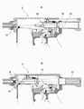
도 1은 본 발명에 관한 총에 있어서의 볼트 스톱 완충 장치를 적용한 가스 건의 일례를 나타내는 단면 설명도이다.
도 2는 상술한 장치의 주요부를 확대하여 나타내는 단면 설명도이다.
도 3은 도 2의 III-III선에 있어서의 횡단면도이다.
도 4는 상술한 장치의 작동 상태를 나타내는 것으로, A는 최종 탄환의 발사 전 상태, B는 최종 탄환의 발사된 상태를 각각 나타내는 단면 설명도이다.
도 5는 상술한 장치의 작동 상태를 나타내는 것으로, A는 볼트가 최대한 후퇴한 상태, B는 볼트가 전진을 개시한 상태를 각각 나타내는 단면 설명도이다.
도 6은 상술한 장치의 작동 상태를 나타내는 것으로, A는 볼트 스톱 부재의 최대 전진 위치를 나타내는 상태, B는 완충 스프링에 의하여 긴 구멍의 범위에서 볼트 스톱 부재가 후퇴한 상태를 각각 나타내는 단면 설명도이다.
도 7은 가스 건의 작동을 나타내는 것으로, A는 볼트를 수동으로 후퇴시킨 상태, B는 수동 조작으로 탄환이 장전된 상태를 각각 나타내는 단면 설명도이다.
도 8은 가스 건의 작동을 나타내는 것으로, A는 탄환이 발사된 상태, B는 볼트가 후퇴를 개시한 상태를 각각 나타내는 단면 설명도이다.
도 9는 가스 건의 작동을 나타내는 것으로, A는 볼트에 의하여 해머를 코킹하고 있는 상태, B는 피스톤이 후퇴를 개시한 상태를 각각 나타내는 단면 설명도이다.
도 10은 가스 건의 작동을 나타내는 것으로, A는 볼트가 최대 후퇴 위치에 있는 상태, B는 볼트가 전진함과 함께 탄환이 장탄부에 공급된 상태를 각각 나타내는 단면 설명도이다.BRIEF DESCRIPTION OF THE DRAWINGS It is sectional explanatory drawing which shows an example of the gas gun to which the bolt stop shock absorber in the gun which concerns on this invention is applied.
Fig. 2 is a cross-sectional explanatory view showing an enlarged main part of the above-described device.
Fig. 3 is a cross-sectional view taken along line III-III in Fig. 2;
4 is a cross-sectional explanatory view showing the state of operation of the above-described device, A is a state before the firing of the final bullet, and B is a cross-sectional explanatory view showing a state in which the final bullet is fired.
5 is a cross-sectional explanatory view showing an operating state of the above-described device, wherein A is a state in which the bolt is retracted to the maximum, and B is a state in which the bolt starts to advance.
6 is a cross-sectional explanatory view showing the state of operation of the device described above, where A is a state showing the maximum forward position of the bolt stop member, and B is a state in which the bolt stop member is retracted from the range of the long hole by the buffer spring. am.
7 is a cross-sectional explanatory view showing the operation of the gas gun, A is a state in which the bolt is manually retracted, and B is a state in which a bullet is loaded by manual operation.
Fig. 8 is a cross-sectional explanatory view showing the operation of the gas gun, wherein A is a state in which a bullet is fired, and B is a state in which the bolt has started retreating.
9 is a cross-sectional explanatory view showing the operation of the gas gun, where A is a state in which the hammer is caulked with a bolt, and B is a state in which the piston starts retraction.
10 is a cross-sectional explanatory view showing the operation of the gas gun, wherein A is a state in which the bolt is in the maximum retracted position, and B is a state in which the bullet is supplied to the magazine unit while the bolt is advanced.
이하 도시한 실시형태를 참조하여 본 발명을 보다 상세하게 설명한다. 본 발명의 총에 있어서의 볼트 스톱 완충 장치는 모든 총에 적용되는 것이며, 가스 건에 한정되는 것은 아니지만, 편의상, 가스 건의 개략에 대하여 먼저 설명한다.The present invention will be described in more detail below with reference to the illustrated embodiments. The bolt stop shock absorber in the gun of the present invention is applied to all guns and is not limited to the gas gun, but for convenience, the outline of the gas gun will be described first.
도 1에 모의총(G)으로서 예시되어 있는 것은 블로백식 가스 건이다. 도시한 모의총(G)은 총 본체의 중앙부에 발사 장치부(10)를 구비하고, 총 본체(10)의 전부(前部)에 배럴부(11), 총 본체의 하부에 매거진부(22), 총 본체의 후부에 블로백용 볼트(29)를 위한 가동체부(30)를 각각 구비하고 있다.What is illustrated as the simulation gun G in FIG. 1 is a blowback type gas gun. The illustrated simulation gun G has a
배럴부(11)에는 장탄부(12)가 후부에 마련되어 있으며, 장탄부(12)에 장전되는 탄환(B)을 향하여, 발사 장치부(10)에 마련된 차압 밸브 기구(20)를 통하여 가스가 분사되고, 그 결과, 탄환(B)이 발사된다. 발사 장치부(10)에는 피스톤 기구부(15)가 있으며, 피스톤 기구부(15)는 배럴 축선 방향으로 이동 가능하게 배치된 피스톤(13)과, 피스톤(13)의 이동 공간의 역할을 하는 실린더(14)를 갖고 있다. 피스톤(13)은, 탄환(B)에 대하여 가스를 분사하는 노즐부(16)를 선단부에 갖고, 또한 실린더(14)의 폐색단부를 향한 개구를 후단부에 갖는 중공 통 형상으로 형성되어 있다.The
피스톤(13)에는, 내외를 통하는 가스 유입구(17)가 전단부쪽의 하부에 개구하고 있으며, 가스 유입구(17)의 부근에 상기의 차압 밸브 기구(20)가 마련되어 있다. 차압 밸브 기구(20)는 선단부의 노즐부(16)와의 사이에 배치된 차압 밸브(18)와, 차압 밸브(18)의 전진 후퇴가 가능한 밸브실(19)과, 밸브실 내에 배치된 반환 스프링(21)을 갖는다. 차압 밸브(18)는, 그 외경이 밸브실(19)의 내경에 대하여 미끄럼 끼워맞춤 정도의 치수차가 되도록 설정되어 있다.In the
또, 차압 밸브(18)는 선단부 측이 개구하고, 후단부 측이 폐쇄된 통형 밸브로 이루어지며, 그 둘레면에 가스 통공(18a)을 갖고 있다. 따라서, 반환 스프링(21)에 의하여 후퇴하여 장탄부(12)에 있는 탄환(B)을 발사시키고, 그 후에도 계속해서 유입되는 가스의 압력에 의하여 전진하여 밸브를 폐쇄함과 함께, 가스 흐름을 실린더(14)에 유도하는 구성이다. 이와 같이 압력차에 의하여 밸브체의 작동 방향이 변하기 때문에, 차압 밸브라고 칭한다. 가스 흐름은 실린더(14)에 유도되어, 블로백 동작에 이용된다.Moreover, the
가스는, 매거진부(22) 내의 가스 탱크(23)에 충전되어 있으며, 그곳으로부터 후술하는 트리거 조작에 따라, 개폐 밸브 기구(25)를 통하여 피스톤 기구부(15)에 공급된다. 개폐 밸브 기구(25)는, 가스 탱크(23)로부터 피스톤 기구부(15)에 도달하는 가스 유로(24), 가스 유로(24)의 개폐를 위하여 마련된 개폐 밸브(26)를 갖고, 가스 유로단부의 유출구(27)로부터 가스를 유입구(17)로 유출시킨다. 또한, 개폐 밸브(26)는, 트리거 조작에 의하여 작동하는 후술하는 해머(40)에 의하여 타압(打壓)되도록, 외부에 노출된 밸브축(26a)을 갖고 있다.Gas is filled in the
피스톤 기구부(15)에 있어서, 피스톤(13)은 인장 스프링으로 이루어지는 리턴 스프링(28)에 의하여 후방으로 부세되어 있다. 상기 피스톤 리턴 스프링(28)은 전단부가 피스톤 측의 부재(59a)에, 후단부가 실린더 측의 부재(59b)에 장착되어 있다. 볼트(29)는, 모의적인 리코일 쇼크를 체감시키기 위하여 필요한 질량을 구비하고 있으며, 실시형태의 볼트(29)는 전후로 가늘고 긴 축 형상으로 형성되어 있다. 또한, 실린더(14)는, 볼트(29)와 일체적으로 마련되어 있으며, 따라서, 실린더(14)의 질량은 볼트(29)에 더해지게 된다.In the piston mechanism (15), the piston (13) is biased backward by a return spring (28) made of a tension spring. The
상기 볼트(29)의 후방에는 가동체부(30)가 배치되어 있으며, 가동체부(30)는 총 본체에 장착된 케이싱(30c)과, 그 내부에 배치된 가동축(30a)을 갖고 있다. 가동축(30a)은 케이싱(30c)의 내부에서 전진 후퇴 가능하게 마련되어 있으며, 축머리(30b)에서 볼트(29)의 후단부와 계합하도록 구성되어 있다. 도면 중, 부호 31은 버퍼 스프링을 나타내고 있으며, 버퍼 스프링(31)은 가동축(30a)을 전진 방향으로 부세하고, 그로써 최종적으로는 피스톤 기구부(15)를 발사 준비 상태로 두도록 작용한다. 또, 버퍼 스프링(31)은 볼트(29)를 후퇴 동작 시에 저지하여, 리코일 쇼크 종료 시의 충격을 조정하는 수단으로서도 기능한다.A
발사 장치부(10)의 작동을 위하여, 트리거(32)가 마련되어 있다. 트리거(32)는 두 부재 32A, 32B를 조합하여 구성되어 있으며, 트리거 부재(32A)는 조작부, 또 트리거 부재(32B)는 피조작 부재이다. 이들 두 부재 32A, 32B는 축(33)을 중심으로 회전 가능하고, 트리거 스프링(34)에 의하여, 서로 이간하는 방향으로 부세되어 있다. 35는 디스커넥터이며, 트리거 부재(32A)에 동축으로 마련되어 연사, 단사의 선택을 가능하게 하는 것으로, 셀렉터(36)에 의하여 제어된다.A
트리거 부재(32A)는, 상술한 해머(40)를 코킹 상태로 계지한다. 37은 코킹 상태로 유지하는 트리거 측의 계지부, 38은 마찬가지로 해머 측의 계지부를 나타낸다. 39는 해머 스프링으로, 코킹 시에 축압 상태가 된다. 따라서, 트리거(32A)를 조작하면, 계지부(37, 38)의 계합이 해제되므로 해머 스프링(39)의 축압도 해방되어, 해머(40)가 작동하게 된다.The
상기 해머(40)는, 코킹 시에 시어(sear)(41)와의 계합 상태에 놓인다. 시어(41)에는 스프링(42)이 작용하고 있으며, 해머(40)의 코킹을 유지하는 방향으로 작용한다. 해머(40)는 실린더(14)의 후퇴에 의하여 코킹된다. 이로 인하여, 실린더(14)의 후단부의 하부에, 캠 형상의 계합 돌기부(43)가 마련되어 있으며, 해머(40)에는 계합 돌기부(44)가 축지지되어 있다. 부호 45는 해머(40)의 타압부이며, 노커(46)를 통하여 밸브축(26a)을 구동한다. 47은 볼트 돌기부를 나타내고 있으며, 시어(41)를 시어 스프링(42)에 저항하여 회전시켜, 코킹 상태에 있는 해머(40)를 회전 가능하게 하는 것이다. 48은 장전 레버(차징 핸들)를 나타내고 있으며, 실린더(14)의 전측에 계합하는 조작에 의하여 후퇴시켜, 해머(40)를 코킹할 수 있다. 돌기부(44, 47)는 단순한 돌기부나 롤 중 어느 쪽이어도 된다.The
본 발명에 관한 총에 있어서의 볼트 스톱 완충 장치는, 도 2에 상세하게 실시형태를 나타내고 있다. 이 실시형태의 가스 건은, 완충 장치의 주요부가 총 본체의 우측에 위치하고 있기 때문에, 편의상, 도 2, 도 4~도 6에서는 총 본체도 도 1 등과는 반대로 우측을 향하여 도시하고 있다.An embodiment of the bolt stop shock absorber in the gun according to the present invention is shown in detail in FIG. 2 . In the gas gun of this embodiment, since the main part of the shock absorber is located on the right side of the gun main body, for convenience, the gun main body is also shown toward the right side in FIG. 2, FIGS. 4-6, as opposed to FIG.
실시형태의 볼트 스톱 완충 장치는, 총의 조작에 따라 축압되고, 버퍼 스프링(31)의 해방에 의하여 전진하는 볼트(29)와, 상기 전진하고 있는 볼트(29)를 정지시키는 볼트 스톱 부재(62)를 구비한 구성을 갖는다. 특히, 실시형태의 것은 탄환 소진 검출 수단(51)의 작동에 의하여, 볼트(29)가 전진 후퇴하는 궤도(X) 내에 볼트 스톱 부재(62)를 돌출시키는 구성을 갖고, 완충 수단(70)을 이용하여, 전진으로 바뀐 볼트(29)와 상기 볼트 스톱 부재(62)가 충돌했을 때에 발생하는 충격을 흡수하는 것이다.In the bolt stop shock absorber of the embodiment, a
매거진부(22)에 장전되어 있는 최후의 탄환(B)이 발사된 것을 검출하기 위하여, 매거진부(22) 내에 장비되고 탄환에 의하여 압축되어 있던 팔로어 스프링(57)이 그 탄발력에 의하여 신장되면, 그에 따라 상승하는 팔로어(53)가 마련되어 있다. 팔로어(53)는 팔로어 레버(53a)를 갖고, 상기 레버(53a)는 팔로어 링크(54)의 일단부(54a)와 계합하여, 탄환 소진 검출 수단(51)의 전단(前段) 부분을 구성한다. 실시형태로서 도시한 탄환 소진 검출 수단(51)은, 축부(54b)에 의하여 요동 가능하게 축지지되어 있는 팔로어 링크(54)와 중간 링크(55)를 더 갖고 있다.In order to detect that the last bullet B loaded in the
팔로어 링크(54)의 타단부(54c)는, 중간 링크(55)의 일단부(55a)와 계합하고 있으며, 팔로어 링크(54)와 중간 링크(55)는, 각각 축부(54b, 55b)에 의하여 요동 가능하게 축지지되어 있다. 중간 링크(55)의 타단부(55c)는 볼트 스톱부(60)와의 사이의 중계 부재(61)의 일단부(61a)와 계합하여, 볼트 스톱부(60)를, 볼트(29)가 전진 후진하는 궤도(X) 내에 돌출시킨다. 팔로어 링크(54)와 중간 링크(55)는, 탄환 소진 검출 수단(51)과 볼트 스톱부(60)를 연락하는 링크 기구(56)를 구성한다.The
상기 중계 부재(61)는, 볼트 스톱 부재(62) 등과 함께 볼트 스톱부(60)를 구성한다. 중계 부재(61)의 일단부(61a)는, 상기 중간 링크(55)의 타단부(55c)와 계합하고, 중계 부재(61)의 타단부(61b)는, 볼트 스톱 부재(62)와 홈부(62a)에서 계합하고 있다. 따라서, 탄환 소진 검출 수단(51)이 탄환 소진을 검출하면, 장탄부(12)에 배치된 탄환(B)이 다 발사되었다는 탄환 소진 정보가 링크 기구(56)에 의하여 볼트 스톱부(60)까지 차례로 전달되게 된다.The
도 3을 참조하면, 중계 부재(61)는 총 본체의 좌우에 걸쳐지는 부재로서 도시되어 있으며, 좌측의 축(61c)에 의하여 총 본체 측에 축지지되어, 축을 중심으로 한 회전에 의하여 우측의 부분(도 2에 크랭크 형상으로 나타나 있음)이 상하 이동 가능하게 되도록 마련되어 있다. 또, 중계 부재(61)는, 축(61c)의 상부에 위치하여 총 본체 좌측에 나타나는 조작부(61d)를 갖고, 하부에는 스프링(61e)이 작용하고 있으며, 중계 부재(61)를 정위치로 되돌리고, 또한 후술하는 볼트 스톱 부재(62)를 눌러 내리도록 마련되어 있다.Referring to FIG. 3 , the
볼트 스톱 부재(62)에는 전후 방향의 긴 구멍(62b)이 형성되어, 축(65)에 의하여 총 본체 측에 요동 가능하게 축지지되어 있으며, 따라서, 볼트 스톱 부재(62)는 긴 구멍(62b) 내에 있어서의 스트로크양만큼 이동 가능하고, 또한 축(65)을 중심으로 회전 가능하다. 이 구성의 결과, 링크 기구(56)에 의하여, 중계 부재(61)를 통하여, 볼트 스톱 부재(62)의 계합 상대부(62c) 측이 상승하여, 볼트(29)가 전진 후진하는 궤도(X) 내에 돌출 가능해진다.The
볼트(29)에는 계합 수단(59)의 일방으로서 계합부(29a)가 마련되어 있으며, 이 계합부(29a)는, 계합 수단(59)의 타방으로서 상기 볼트 스톱 부재(62)에 마련되어 있는 계합 상대부(62c)와 계합 가능하게 구성되어 있다. 특히, 실시형태의 상기 계합부(29a)와 계합 상대부(62c)는, 볼트(29)의 전진 방향에 대하여 예각을 구성하는 경사부로서 마련되어 있다. 상기 계합부(29a)와 계합 상대부(62c)의 경사는, 볼트 스톱 부재(62)가 전후 방향의 긴 구멍(62b)에서 축(65)에 의하여 축지지되어 있기 때문에, 계합부(29a)와 계합 상대부(62c)를 직각으로 한 경우에 일어날 수 있는, 계합의 불안정을 해소하여 확실화를 도모하려는 의도이다.The
상기 볼트 스톱부(60)에는 완충 수단(70)이 작용하고 있다. 실시형태의 완충 수단(70)은, 완충 링크(67)와, 총 본체 측의 장착부(66)에 전후 방향으로 이동 가능하게 도입된 완충축(68) 및 완충 스프링(69)을 갖고 있다. 상기 완충 링크(67)는 축(67b)에 의하여 총 본체 측에 요동 가능하게 축지지되어 있으며, 일단부가 볼트 스톱 부재(62)의 전부 계합부(62d)에 계합하고, 타단부는 완충축(68)의 선단부에 계합한다. 따라서, 볼트(29)의 전진에 따른 충돌 시에 볼트 스톱부(62)가 총구 방향으로 이동하는 충격이 완충 수단(70)에 전달된다.A buffer means 70 is acting on the
또한, 중계 부재(61)와 볼트 스톱 부재(62)는, 총구로부터 총대의 방향으로 나열되어 있기 때문에, 볼트(29)가 전진할 때에 볼트 스톱부(60)에 있어서의 볼트 스톱 부재(62)와 충돌하지만, 중계 부재(61)는 볼트(29)에 접촉하지 않는 형상이며, 볼트 스톱 부재(62)가 최대 이동 시에도 접촉하지 않는 형상이기 때문에, 중계 부재(61)에는 직접 접촉하지 않는다. 볼트 스톱 부재(62)는 긴 구멍(62b)에서 축(65)과 계합하고 있기 때문에, 긴 구멍(62b)의 길이를 최대 한도로서 이동 가능하다. 최대 이동 시, 볼트 스톱 부재(62)의 홈부(62a)에, 중계 부재(61)의 타단부(61b)가 더 들어가는 상태가 된다.In addition, since the
이와 같이 구성된 본 발명의 총에 있어서의 볼트 스톱 완충 장치에 있어서, 최종 탄환(B)이 장탄부(12)에 있는 상태에 있어서(도 4A), 탄환(B)이 발사되어, 매거진부(22)의 탄환(B)이 비게 되면, 볼트(29)가 후퇴를 개시하고, 팔로어(53)가 팔로어 스프링(57)의 탄발력에 의하여 장탄부(12)의 후방 부근의 최고 위치까지 상승하여, 팔로어 레버(53a)와 계합하는 팔로어 링크(54)의 일단부(54a)가 밀어 올려진다(도 4B). 이 밀어 올림에 따른 동작은, 팔로어 링크(54)로부터 중간 링크(55) 및 중계 부재(61)를 통하여 볼트 스톱 부재(62)에까지 전달된다.In the bolt stop shock absorber for the gun of the present invention configured as described above, in the state in which the final bullet B is in the loading portion 12 (FIG. 4A), the bullet B is fired, and the magazine portion 22 ) when the bullet (B) is empty, the
볼트(29)가 최대한 후퇴한 상태가 되면(도 5A), 팔로어(53)는 최고 위치까지 상승을 완료하고, 상기 링크 기구(56)의 전달 작용에 의하여 볼트 스톱 부재(62)의 작동이 완료된다. 그 결과, 볼트 스톱 부재(62)는 축(65)을 중심으로 회전하여, 선단부 측이 중계 부재(61)에 의하여 밀어 올려지고, 경사부로 이루어지는 계합 상대부(62c)는, 볼트(29)가 전진 후진하는 궤도(X) 내에 돌출된다. 볼트(29)는, 후퇴에 따라 축압된 버퍼 스프링(31)의 탄발력을 받아 전진으로 바뀌고, 계합부(29a)와 계합 상대부(62c)가 경사부에서 계합한다(도 5B).When the
볼트(29)가 더 전진하면, 볼트 스톱 부재(62)는 계합 수단(59)에 의하여 전방으로 연행되고, 축(65)은 배치되어 있는 긴 구멍(62b)의 전단부로부터 후단부로 이동한다(도 6A). 볼트 스톱 부재(62)가 상기 이동을 하는 동안에, 그 전부 계합부(62d)가 계합하고 있는 완충 링크(67)를 일단부(67a)에 의하여 압압하고, 타단부(67c)에 의하여, 계합하고 있는 완충축(68)을 압압한다. 따라서, 볼트(29)의 전진에 따른 충돌 시에 볼트 스톱부(62)가 총구 방향으로 이동하는 충격이 완충 수단(70)에 흡수되어, 볼트(29)는 완만하게 정지한다. 이어서, 완충 스프링(69)의 탄성력에 의하여 볼트 스톱 부재(62)가 후방으로 밀려 되돌아오고, 볼트(29)는 도 5B의 위치까지 후퇴하여, 완충 장치의 작동이 완료된다.When the
또한, 본 발명에 있어서의 모의총(G)에 대하여, 전체적인 작동을 설명하면 이하와 같다. 장전 레버(48)의 수동 조작에 의하여 볼트(29)를 후퇴시켜, 해머(40)를 코킹 상태로 한다(도 7A의 상태). 장전 레버(48)를 놓으면 볼트(29)는 버퍼 스프링(31)에 의하여 전진하고, 그것과 일체적으로 이동하는 피스톤 기구부(15)의 노즐부(16)에 의하여, 일발의 탄환(B)이 장탄부(12)에 장전된다(도 7B).In addition, with respect to the simulation gun G in this invention, when the whole operation is demonstrated, it is as follows. The
이어서, 트리거(32A)를 당겨 해머(40)가 작동하면 노커(46)를 통하여 밸브축(26a)이 밀려들어가, 개폐 밸브 기구(25)가 밸브를 개방하여, 압축 가스가 가스 유입구(17)에 유입된다. 압축 가스는, 차압 밸브 기구(20)의 가스 통구(18a)로부터 차압 밸브(18)의 내부에 유입되어, 탄환(B)에 분사되고, 그 결과, 탄환(B)은 배럴(11)로부터 발사된다(도 8A). 탄환 발사 후에도 계속해서 유입되는 가스의 압력에 의하여, 차압 밸브(18)가 전진하여 차압 밸브 기구(20)가 밸브를 폐쇄함과 함께, 가스 흐름은 실린더(14)에 유도된다(도 8B).Next, when the
가스 흐름의 실린더(14) 내로의 유입에 의하여 피스톤 기구부(15)가 볼트(29)와 함께 후퇴하고, 그 과정에서 해머(40)가 코킹된다(도 9A). 볼트(29)가 어느 정도 후퇴하면, 피스톤 스톱(50)과 함께 피스톤(13)이 후퇴를 개시하고, 또한 피스톤 리턴 스프링(28)에 의하여 볼트 방향으로 끌어 당겨진다(도 9B).The inflow of the gas flow into the
볼트(29)는 피스톤 기구부(15)와 함께 최대 후퇴 위치까지 후퇴 후에 정지하고(도 10A), 모의총(G)의 조작자는, 이 사이에 볼트(29)의 질량의 이동에 따른 쇼크를 체감한다. 상기 후퇴 동작에 의하여 축압된 버퍼 스프링(31)이 해방되어, 볼트(29)가 전진으로 바뀌고, 그것과 일체적으로 이동하는 피스톤 기구 선단부의 노즐부(16)에 의하여, 일발의 탄환(B)이 장탄부(12)에 장전된다(도 10B). 또한 볼트(29)의 돌기부(47)가 시어(41)를 회전시킴으로써 해머(40)가 개방되어, 도 7B의 상태로 되돌아가 발사 동작이 반복된다(연사 모드). 단사 모드의 경우에는, 해머(40)가 디스커넥터(35)에, 계합부(35a, 40a)에 의하여 계합하여 정지한다. 그 계지는 트리거(32)를 되돌림으로써 분리되므로, 해머(40)는 트리거(32)에 계지되어 코킹 상태로 유지되게 된다.The
본 발명의 총에 있어서의 볼트 스톱 완충 장치는, 볼트(29)를 정지시키는 볼트 스톱 부재(62)를 완충 수단(70)에 의하여 간접적으로 완충하여, 그 손상을 방지하고, 갑작스러운 작동 부전을 발생하지 않도록 총을 보호할 수 있다. 또, 본 발명의 장치에서는, 탄환(B)이 다 발사되었다는 탄환 소진을 검출하고, 매거진을 교환하여 재장전할 때에 볼트 스톱 부재(62)를 해제함으로써, 다시 장전 레버(차징 핸들)를 조작할 필요가 없어지는 기능이 유지된다.The bolt stop shock absorber in the gun of the present invention indirectly buffers the
10 발사 장치부
11 배럴부
12 장탄부
13 피스톤
14 실린더
15 피스톤 기구부
16 노즐부
17 가스 유입구
18 차압 밸브
19 밸브실
20 차압 밸브 기구
21 반환 스프링
22 매거진부
23 가스 탱크
24 가스 유로
25 개폐 밸브 기구
26 개폐 밸브
27 유출구
28 피스톤 리턴 스프링
29 볼트
30 가동체부
31 버퍼 스프링
32, 32A, 32B 트리거
33 축
34 트리거 스프링
35 디스커넥터
36 셀렉터
37, 38 계지부
39 해머 스프링
40 해머
41 시어
42 시어 스프링
43 계합 돌기부
44 계합륜
45 타압부
46 노커
47 볼트 돌기부
48 장전 레버
51 탄환 소진 검출 수단
53 팔로어
54 팔로어 링크
55 중간 링크
56 링크 기구
57 팔로어 스프링
59 계합 수단
60 볼트 스톱부
61 중계 부재
62 볼트 스톱 부재
65 축
66 장착부
67 완충 링크
68 완충축
69 완충 스프링
70 완충 수단10 launch device
11 barrel
12 bullets
13 piston
14 cylinder
15 piston mechanism
16 Nozzle
17 gas inlet
18 differential pressure valve
19 valve chamber
20 Differential pressure valve mechanism
21 return spring
22 magazine department
23 gas tank
24 gas euros
25 on-off valve mechanism
26 on-off valve
27 outlet
28 piston return spring
29 volts
30 movable body
31 buffer spring
32, 32A, 32B trigger
33 axis
34 trigger spring
35 Disconnector
36 selector
37, 38 branch
39 hammer spring
40 hammer
41 Shea
42 shear spring
43 engaging projection
44 engagement wheel
45 pressure part
46 knocker
47 bolt protrusion
48 load lever
51 Bullet exhaust detection means
53 followers
54 Follower Links
55 middle link
56 link mechanism
57 follower spring
59 means of engagement
60 volt stop
61 no relay
62 bolt stop member
65 axis
66 mounting
67 buffer link
68 buffer shaft
69 buffer spring
70 buffer
Claims (3)
Translated fromKorean볼트 스톱 부재는, 전진하는 볼트와 계합하는 계합 수단을 갖고, 상기 계합 수단에 의하여 볼트 스톱 부재에 가해지는 충격력을 완충하기 위하여, 볼트 스톱 부재에 작용하는 완충 수단을 구비하고,
총 본체는, 총의 조작에 따라 장탄부에 공급되는 탄환의 유무를 검출하는 탄환 소진 검출 수단을 갖고, 상기 탄환 소진 검출 수단은, 탄환 소진을 검출함으로써, 볼트 스톱 부재를 볼트가 전진 후진하는 궤도 내에 돌출시켜, 계합 수단에 의한 계합을 가능하게 하기 위한 링크 기구를 구비하고 있는 총에 있어서의 볼트 스톱 완충 장치.A gun having a bolt that is provided in the main body of the gun so as to be able to move forward and retractable, and which accumulates pressure on the buffer spring while retracting according to the operation of the gun, and advances by releasing the axial pressure, and a bolt stop member for stopping the bolt in advance. As a bolt stop device in
The bolt stop member has an engaging means that engages with the advancing bolt, and includes a buffering means acting on the bolt stop member in order to buffer an impact force applied to the bolt stop member by the engaging means,
The gun main body has a bullet exhaustion detection means for detecting the presence or absence of a bullet supplied to the ammunition unit according to the operation of the gun, wherein the bullet exhaustion detection means detects the bullet exhaustion, thereby moving the bolt stop member forward and backward. A bolt stop shock absorber for a gun provided with a link mechanism that protrudes inside and enables engagement by an engaging means.
볼트 스톱 부재는, 전진하는 볼트와 계합하는 계합 수단을 갖고, 상기 계합 수단에 의하여 볼트 스톱 부재에 가해지는 충격력을 완충하기 위하여, 볼트 스톱 부재에 작용하는 완충 수단을 구비하고,
볼트 스톱 부재는, 볼트와 완충 수단의 사이에 개재하는 볼트 스톱부를 구성하고 있으며, 총 본체 측에 마련된 축이 배치되는 전후 방향의 긴 구멍을 갖고, 상기 긴 구멍의 범위에서 이동 가능, 또한 축을 중심으로 하여 회전 가능하게 마련되며, 계합 수단은 볼트에 마련된 계합부와 볼트 스톱 부재에 마련된 계합 상대부로 이루어지고, 볼트의 전진 방향에 대하여 예각을 구성하도록 마련되어 있는, 총에 있어서의 볼트 스톱 완충 장치.A gun having a bolt that is provided in the main body of the gun so as to be able to move forward and retractable, and which accumulates pressure on the buffer spring while retracting according to the operation of the gun, and advances by releasing the axial pressure, and a bolt stop member for stopping the bolt in advance. As a bolt stop device in
The bolt stop member has an engaging means that engages with the advancing bolt, and includes a buffering means acting on the bolt stop member in order to buffer an impact force applied to the bolt stop member by the engaging means,
The bolt stop member constitutes a bolt stop portion interposed between the bolt and the shock absorber, has an elongated hole in the front-rear direction in which a shaft provided on the side of the gun body is disposed, and is movable within the range of the long hole and is centered on the shaft. A bolt stop shock absorber for a gun, comprising an engaging portion provided on the bolt and an engaging counterpart provided on the bolt stop member, and provided so as to form an acute angle with respect to the forward direction of the bolt.
볼트 스톱 부재는, 볼트와 완충 수단의 사이에 개재하는 볼트 스톱부를 구성하고 있으며, 총 본체 측에 마련된 축이 배치되는 전후 방향의 긴 구멍을 갖고, 상기 긴 구멍의 범위에서 이동 가능, 또한 축을 중심으로 하여 회전 가능하게 마련되며, 계합 수단은 볼트에 마련된 계합부와 볼트 스톱 부재에 마련된 계합 상대부로 이루어지고, 볼트의 전진 방향에 대하여 예각을 구성하도록 마련되어 있는, 총에 있어서의 볼트 스톱 완충 장치.The method according to claim 1,
The bolt stop member constitutes a bolt stop portion interposed between the bolt and the shock absorber, has an elongated hole in the front-rear direction in which a shaft provided on the side of the gun body is disposed, and is movable within the range of the long hole and is centered on the shaft. A bolt stop shock absorber for a gun, comprising an engaging portion provided on the bolt and an engaging counterpart provided on the bolt stop member, and provided so as to form an acute angle with respect to the forward direction of the bolt.
Applications Claiming Priority (1)
| Application Number | Priority Date | Filing Date | Title |
|---|---|---|---|
| PCT/JP2015/063663WO2016181507A1 (en) | 2015-05-12 | 2015-05-12 | Shock-absorption device for gun bolt stop |
Publications (2)
| Publication Number | Publication Date |
|---|---|
| KR20180011462A KR20180011462A (en) | 2018-02-01 |
| KR102283349B1true KR102283349B1 (en) | 2021-07-29 |
Family
ID=57248979
Family Applications (1)
| Application Number | Title | Priority Date | Filing Date |
|---|---|---|---|
| KR1020177034855AActiveKR102283349B1 (en) | 2015-05-12 | 2015-05-12 | bolt stop shock absorber in gun |
Country Status (6)
| Country | Link |
|---|---|
| US (1) | US10415912B2 (en) |
| EP (1) | EP3296682B1 (en) |
| JP (1) | JP6229082B2 (en) |
| KR (1) | KR102283349B1 (en) |
| CN (1) | CN107615002B (en) |
| WO (1) | WO2016181507A1 (en) |
Families Citing this family (12)
| Publication number | Priority date | Publication date | Assignee | Title |
|---|---|---|---|---|
| KR102362955B1 (en)* | 2015-10-16 | 2022-02-14 | 가부시키가이샤 도쿄 마루이 | bolt stop shock absorber in gun |
| WO2019013806A1 (en)* | 2017-07-14 | 2019-01-17 | Mustang Industrial Design, Inc. | Auto-loading hammer-type firearm with selectable live fire and training modes |
| WO2019058525A1 (en)* | 2017-09-22 | 2019-03-28 | 株式会社東京マルイ | Device for inhibiting firing of shells in an electric gun |
| JP6934206B2 (en)* | 2017-09-22 | 2021-09-15 | 株式会社東京マルイ | Empty shot prevention function stop device |
| US10760862B2 (en)* | 2018-10-09 | 2020-09-01 | Daniel Defense, Inc. | Bolt stop assemblies |
| RU2705410C1 (en)* | 2018-12-25 | 2019-11-07 | Василий Михайлович Покаляев | Automatic firearm with automation based on inertial system |
| US11029110B2 (en) | 2019-04-05 | 2021-06-08 | Smith & Wesson Inc. | Magazine safety |
| JP7387144B2 (en)* | 2019-09-24 | 2023-11-28 | 株式会社東京マルイ | toy gun |
| RU200564U1 (en)* | 2020-07-07 | 2020-10-29 | Сергей Борисович Епаров | SHOOTING PNEUMATIC DEVICE |
| RU201681U1 (en)* | 2020-09-02 | 2020-12-28 | Сергей Борисович Епаров | OFFSET NOZZLE REDUCER REDUCER PNEUMATIC UNIT |
| CN113654398B (en)* | 2020-11-10 | 2023-03-17 | 马常鸣 | Electric cartridge clip with empty hanging function |
| JP7614927B2 (en) | 2021-04-23 | 2025-01-16 | 株式会社東京マルイ | Toy guns and magazines |
Family Cites Families (17)
| Publication number | Priority date | Publication date | Assignee | Title |
|---|---|---|---|---|
| US3380183A (en)* | 1965-02-12 | 1968-04-30 | Armalite Inc | Upper handguard fixedly mounted on barrel assembly by breechblock guide rods |
| US3563132A (en)* | 1968-09-19 | 1971-02-16 | Us Navy | Grenade launcher |
| US4244273A (en)* | 1978-12-04 | 1981-01-13 | Langendorfer Plastics Corporation | Rifle modification |
| GB8724995D0 (en)* | 1987-09-11 | 1988-01-27 | Victory Arms Co Ltd | Breech locking system for self loading firearms |
| US4955812A (en)* | 1988-08-04 | 1990-09-11 | Hill Banford R | Video target training apparatus for marksmen, and method |
| US5457901A (en)* | 1994-01-12 | 1995-10-17 | Gernstein; Terry M. | Recoil absorption means for a shotgun |
| US5735070A (en)* | 1996-03-21 | 1998-04-07 | Vasquez; Eduardo C. | Illuminated gun sight and low ammunition warning assembly for firearms |
| JP2960023B2 (en)* | 1996-12-29 | 1999-10-06 | 株式会社ウエスタン・アームス | Automatic fire toy gun |
| US6192780B1 (en)* | 1999-03-29 | 2001-02-27 | Bryan S. Schneider | Forward receiver buffer |
| US6510778B1 (en)* | 2000-12-28 | 2003-01-28 | Custom Shooting Technologies, Inc. | Automatic bolt hold-open assembly |
| US20040144012A1 (en)* | 2003-01-29 | 2004-07-29 | Adams Joseph S. | Combustion-gas-powered paintball marker |
| AU2007240122A1 (en)* | 2006-04-19 | 2007-10-25 | Goodcart Pty Ltd | A bolt head locking arrangement for firearm weapons |
| US7694448B2 (en)* | 2006-12-27 | 2010-04-13 | Tokyo Marui Co., Ltd. | Recoil shock device in toy gun |
| ITMI20071909A1 (en)* | 2007-10-04 | 2009-04-05 | Beretta Armi Spa | FIREARMS WITH PERFECTED SHUTTER GROUP |
| CH699667A2 (en)* | 2008-10-09 | 2010-04-15 | Gamma Kdg Systems Sa | New mechanism for opening automatic weapon delay. |
| US8117957B2 (en)* | 2009-07-24 | 2012-02-21 | Vladimir Loganchuk | Breech device for a hand firearm |
| US9217614B2 (en)* | 2011-02-11 | 2015-12-22 | Jorge Pizano | Firearm having an articulated bolt train with transversally displacing firing mechanism, delay blowback breech opening, and recoil damper |
- 2015
- 2015-05-12KRKR1020177034855Apatent/KR102283349B1/enactiveActive
- 2015-05-12CNCN201580079841.9Apatent/CN107615002B/enactiveActive
- 2015-05-12JPJP2016576088Apatent/JP6229082B2/enactiveActive
- 2015-05-12EPEP15891831.8Apatent/EP3296682B1/enactiveActive
- 2015-05-12USUS15/572,881patent/US10415912B2/enactiveActive
- 2015-05-12WOPCT/JP2015/063663patent/WO2016181507A1/ennot_activeCeased
Also Published As
| Publication number | Publication date |
|---|---|
| CN107615002B (en) | 2020-04-28 |
| HK1243479A1 (en) | 2018-07-13 |
| EP3296682A1 (en) | 2018-03-21 |
| KR20180011462A (en) | 2018-02-01 |
| US20180112942A1 (en) | 2018-04-26 |
| JPWO2016181507A1 (en) | 2017-06-01 |
| EP3296682A4 (en) | 2018-12-19 |
| EP3296682B1 (en) | 2021-03-24 |
| WO2016181507A1 (en) | 2016-11-17 |
| CN107615002A (en) | 2018-01-19 |
| JP6229082B2 (en) | 2017-11-08 |
| US10415912B2 (en) | 2019-09-17 |
Similar Documents
| Publication | Publication Date | Title |
|---|---|---|
| KR102283349B1 (en) | bolt stop shock absorber in gun | |
| US4244273A (en) | Rifle modification | |
| CA2396031A1 (en) | Pneumatic gun | |
| KR102283347B1 (en) | The shock absorber of the piston mechanism in the simulation gun | |
| CA2653036C (en) | Locking mechanism of a hand firearm | |
| US3680433A (en) | Semi-automatic shotgun having rotary and sliding breech block | |
| EP3064882B1 (en) | Toy gun | |
| KR102362955B1 (en) | bolt stop shock absorber in gun | |
| US3225657A (en) | Closed breech gun | |
| US4016800A (en) | Portable firearm with a retractable barrel | |
| US3503299A (en) | Air operated projectile firing apparatus | |
| RU2124173C1 (en) | Multiple small arms | |
| JP2877805B1 (en) | Valve device for blowback type gas gun | |
| US1146984A (en) | Firearm. | |
| KR102851959B1 (en) | Rifle for training purposes with air pressure recoil system | |
| HK1243479B (en) | Bolt stop shock-absorption device in gun | |
| US20220136786A1 (en) | Gun with a delay function | |
| JP6758721B2 (en) | Cocking indicator device in simulated gun | |
| KR20240000471A (en) | dual fire mode semi-automatic pistol | |
| CZ306969B6 (en) | A sealed single-action revolver | |
| HK1260699A1 (en) | Cocking indicator apparatus in simulation gun | |
| HK1242763B (en) | Shock-absorption device of piston mechanism in simulation gun |
Legal Events
| Date | Code | Title | Description |
|---|---|---|---|
| PA0105 | International application | Patent event date:20171201 Patent event code:PA01051R01D Comment text:International Patent Application | |
| PG1501 | Laying open of application | ||
| A201 | Request for examination | ||
| PA0201 | Request for examination | Patent event code:PA02012R01D Patent event date:20200408 Comment text:Request for Examination of Application | |
| E902 | Notification of reason for refusal | ||
| PE0902 | Notice of grounds for rejection | Comment text:Notification of reason for refusal Patent event date:20210126 Patent event code:PE09021S01D | |
| E701 | Decision to grant or registration of patent right | ||
| PE0701 | Decision of registration | Patent event code:PE07011S01D Comment text:Decision to Grant Registration Patent event date:20210701 | |
| PR0701 | Registration of establishment | Comment text:Registration of Establishment Patent event date:20210723 Patent event code:PR07011E01D | |
| PR1002 | Payment of registration fee | Payment date:20210726 End annual number:3 Start annual number:1 | |
| PG1601 | Publication of registration |