KR102282284B1 - Method, apparatus, device, and storage medium for providing visual representation of set of objects - Google Patents
Method, apparatus, device, and storage medium for providing visual representation of set of objectsDownload PDFInfo
- Publication number
- KR102282284B1 KR102282284B1KR1020200000261AKR20200000261AKR102282284B1KR 102282284 B1KR102282284 B1KR 102282284B1KR 1020200000261 AKR1020200000261 AKR 1020200000261AKR 20200000261 AKR20200000261 AKR 20200000261AKR 102282284 B1KR102282284 B1KR 102282284B1
- Authority
- KR
- South Korea
- Prior art keywords
- location
- information
- objects
- visual representation
- providing
- Prior art date
- Legal status (The legal status is an assumption and is not a legal conclusion. Google has not performed a legal analysis and makes no representation as to the accuracy of the status listed.)
- Active
Links
Images


Classifications
- G—PHYSICS
- G06—COMPUTING OR CALCULATING; COUNTING
- G06T—IMAGE DATA PROCESSING OR GENERATION, IN GENERAL
- G06T7/00—Image analysis
- G06T7/70—Determining position or orientation of objects or cameras
- G06T7/77—Determining position or orientation of objects or cameras using statistical methods
- G—PHYSICS
- G06—COMPUTING OR CALCULATING; COUNTING
- G06F—ELECTRIC DIGITAL DATA PROCESSING
- G06F16/00—Information retrieval; Database structures therefor; File system structures therefor
- G06F16/90—Details of database functions independent of the retrieved data types
- G06F16/904—Browsing; Visualisation therefor
- G—PHYSICS
- G06—COMPUTING OR CALCULATING; COUNTING
- G06F—ELECTRIC DIGITAL DATA PROCESSING
- G06F16/00—Information retrieval; Database structures therefor; File system structures therefor
- G06F16/20—Information retrieval; Database structures therefor; File system structures therefor of structured data, e.g. relational data
- G06F16/28—Databases characterised by their database models, e.g. relational or object models
- G06F16/284—Relational databases
- G06F16/285—Clustering or classification
- G06F16/287—Visualization; Browsing
- G—PHYSICS
- G06—COMPUTING OR CALCULATING; COUNTING
- G06T—IMAGE DATA PROCESSING OR GENERATION, IN GENERAL
- G06T7/00—Image analysis
- G06T7/70—Determining position or orientation of objects or cameras
- G06T7/73—Determining position or orientation of objects or cameras using feature-based methods
- G06T7/74—Determining position or orientation of objects or cameras using feature-based methods involving reference images or patches
Landscapes
- Engineering & Computer Science (AREA)
- Theoretical Computer Science (AREA)
- Databases & Information Systems (AREA)
- Physics & Mathematics (AREA)
- General Physics & Mathematics (AREA)
- Data Mining & Analysis (AREA)
- General Engineering & Computer Science (AREA)
- Computer Vision & Pattern Recognition (AREA)
- Bioinformatics & Cheminformatics (AREA)
- Bioinformatics & Computational Biology (AREA)
- Evolutionary Biology (AREA)
- Probability & Statistics with Applications (AREA)
- Life Sciences & Earth Sciences (AREA)
- User Interface Of Digital Computer (AREA)
- Digital Computer Display Output (AREA)
- Information Retrieval, Db Structures And Fs Structures Therefor (AREA)
- Controls And Circuits For Display Device (AREA)
- Information Transfer Between Computers (AREA)
Abstract
Translated fromKoreanDescription
Translated fromKorean본 개시의 실시예는 주로 컴퓨터 분야에 관한 것으로, 더 구체적으로, 오브젝트 집합의 시각적 표현을 제공하는 방법, 장치, 기기 및 컴퓨터 판독가능 저장 매체에 관한 것이다.Embodiments of the present disclosure relate primarily to the field of computers, and more particularly, to a method, apparatus, apparatus, and computer-readable storage medium for providing a visual representation of a set of objects.
정보화 시대의 발전에 따라, 점점 더 많은 오브젝트 정보가 그래프라는 형식으로 취합되고 있다. 예를 들면, 지식 그래프의 가시화는 더욱 직관적인 이미지 형식으로 사용자한테지식을 제공함으로써, 사용자가 지식 정보를 획득하는 효율을 향상시킨다. 또한, 지식 그래프의 시각적 표현은 오브젝트들 사이의 상호 관계를 나타낼 수 있고, 오브젝트 관련 속성 정보를 나타낼 수 있는바, 단일 오브젝트가 나타내는 정보를 풍부히 한다. 따라서, 지식 그래프 정보 등과 같은 오브젝트 집합의 시각적 표현으로써 더욱 고효율적으로 사용자한테 필요한 정보를 제공하는 것이 현재 주목의 초점으로 되어 있다.With the development of the information age, more and more object information is being collected in the form of a graph. For example, the visualization of a knowledge graph is a more intuitive image format for usersBy providing knowledge, the efficiency in which the user acquires knowledge information is improved. In addition, the visual representation of the knowledge graph can represent the interrelationship between objects and can represent object-related attribute information, thereby enriching the information represented by a single object. Accordingly, it is currently the focus of attention to provide necessary information to the user more efficiently as a visual representation of a set of objects such as knowledge graph information.
본 개시의 예시 실시예에 따르면, 오브젝트 집합의 시각적 표현을 제공하는 기술안이 제공된다.According to an exemplary embodiment of the present disclosure, a technical proposal for providing a visual representation of a set of objects is provided.
본 개시의 제1 측면으로, 오브젝트 집합의 시각적 표현을 제공하는 방법이 제공된다. 당해 방법은, 드로잉(drawing) 영역 내에서 오브젝트 집합중의 제1 오브젝트의 제1 표시 정보를 제공하는 제1 위치를 결정하는 단계; 드로잉 영역 내의 복수의 소정 위치 중에서 제1 위치에 연관되는 사용 가능 위치를 결정하는 단계; 오브젝트 집합에서 제1 오브젝트에 연관되는 제2 오브젝트를 결정하는 단계; 및 사용 가능 위치에서 제2 오브젝트의 제2 표시 정보를 제공하는 단계; 를 포함한다.In a first aspect of the present disclosure, a method is provided for providing a visual representation of a set of objects. The method includes the steps of: determining a first position in a drawing area that provides first display information of a first object in a set of objects; determining an available location associated with the first location from among a plurality of predetermined locations within the drawing area; determining a second object associated with the first object in the object set; and providing second display information of the second object in the usable location; includes
본 개시의 제2 측면으로, 오브젝트 집합의 시각적 표현을 제공하는 장치가 제공된다. 당해 장치는, 드로잉 영역 내에서 오브젝트 집합중의 제1 오브젝트의 제1 표시 정보를 제공하는 제1 위치를 결정하도록 구성되는 제1 위치 결정 모듈; 드로잉 영역 내의 복수의 소정 위치 중에서 제1 위치에 연관되는 사용 가능 위치를 결정하도록 구성되는 사용 가능 위치 결정 모듈; 오브젝트 집합에서 제1 오브젝트에 연관되는 제2 오브젝트를 결정하도록 구성되는 제2 오브젝트 결정 모듈; 및 사용 가능 위치에서 제2 오브젝트의 제2 표시 정보를 제공하도록 구성되는 제공 모듈; 을 포함한다.In a second aspect of the present disclosure, an apparatus for providing a visual representation of a set of objects is provided. The apparatus includes: a first position determining module, configured to determine a first position providing first display information of a first object in a set of objects in the drawing area; an available location determining module, configured to determine an available location associated with the first location from among a plurality of predetermined locations within the drawing area; a second object determining module, configured to determine a second object associated with the first object in the object set; and a providing module, configured to provide second display information of the second object in the usable location; includes
본 개시의 제3 측면으로, 기기가 제공되는바, 하나 또는 복수의 프로세서; 및 하나 또는 복수의 프로그램을 저장하는 저장 장치; 를 포함하고, 하나 또는 복수의 프로그램이 하나 또는 복수의 프로세서에 의해 실행될 경우, 하나 또는 복수의 프로세서는 본 개시의 제1 측면에 따른 방법을 구현한다.In a third aspect of the present disclosure, an apparatus is provided, comprising: one or a plurality of processors; and a storage device for storing one or a plurality of programs; and, when one or more programs are executed by one or more processors, the one or more processors implement the method according to the first aspect of the present disclosure.
본 개시의 제4 측면으로, 컴퓨터 프로그램이 저장되어 있는 컴퓨터 판독가능 저장 매체가 제공되는바, 당해 프로그램이 프로세서에 의해 실행될 경우, 본 개시의 제1 측면에 따른 방법을 구현한다.As a fourth aspect of the present disclosure, there is provided a computer readable storage medium having a computer program stored thereon. When the program is executed by a processor, the method according to the first aspect of the present disclosure is implemented.
발명 내용 부분에서 설명하는 내용은 본 개시의 실시예의 핵심 특징 또는 중요 특징을 한정하고자 하는 것이 아니며 본 개시의 범위를 제한하기 위한 것도 아님을 이해하여야 한다. 본 개시의 기타 특징은 이하의 설명을 통하여 이해하기 쉽게 될 것이다.It should be understood that the content described in the content of the present disclosure is not intended to limit key features or important features of embodiments of the present disclosure, nor is it intended to limit the scope of the present disclosure. Other features of the present disclosure will become easy to understand through the following description.
첨부 도면을 결부하고 이하 상세한 설명을 참조하면, 본 개시의 각 실시예의 상술한 특징과 기타의 특징, 이점 및 측면은 더욱 분명해질 것이다. 첨부 도면에서, 동일 또는 유사한 도면 부호는 동일 또는 유사한 요소를 표시한다.
도1은 본 개시의 복수의 실시예가 구현될 수 있는 예시 환경의 개략도를 도시한다.
도2는 본 개시의 실시예에 따른 오브젝트 집합의 시각적 표현을 제공하는 과정의 흐름도를 도시한다.
도3은 본 개시의 실시예에 따른 소정 드로잉 영역을 설정하는 개략도를 도시한다.
도4는 본 개시의 실시예에 따른 사용 가능 위치를 결정하는 과정의 개략도를 도시한다.
도5는 본 개시의 실시예에 따른 사용 가능 위치를 결정하는 개략도를 도시한다.
도6은 본 개시의 실시예에 따른 예시적인 시각적 표현의 개략도를 도시한다.
도7은 본 개시의 실시예에 따른 오브젝트 집합의 시각적 표현을 제공하는 장치의 개략적인 블록도를 도시한다.
도8은 본 개시의 복수의 실시예를 실시 가능한 컴퓨팅 기기의 블록도를 도시한다.The above-described and other features, advantages and aspects of each embodiment of the present disclosure will become more apparent with reference to the accompanying drawings and reference to the following detailed description. In the accompanying drawings, the same or similar reference numbers indicate the same or similar elements.
1 depicts a schematic diagram of an example environment in which multiple embodiments of the present disclosure may be implemented.
2 illustrates a flowchart of a process for providing a visual representation of a set of objects according to an embodiment of the present disclosure;
3 is a schematic diagram of setting a predetermined drawing area according to an embodiment of the present disclosure.
4 shows a schematic diagram of a process for determining an available location according to an embodiment of the present disclosure;
5 shows a schematic diagram of determining an usable location according to an embodiment of the present disclosure;
6 depicts a schematic diagram of an exemplary visual representation in accordance with an embodiment of the present disclosure.
7 shows a schematic block diagram of an apparatus for providing a visual representation of a set of objects according to an embodiment of the present disclosure;
8 is a block diagram of a computing device capable of implementing a plurality of embodiments of the present disclosure.
아래, 첨부 도면을 참조하여 본 개시의 실시예에 대해 더 상세하게 설명하고자 한다. 비록 첨부 도면에 본 개시의 어떤 실시예가 표시되었지만, 본 개시는 여러 가지 형식으로 구현 가능한 것으로, 여기서 서술하는 실시예에 한정되는 것으로 해석되어서는 안되고, 반대로, 이러한 실시예를 제공하는 것은 본 개시를 더욱 투철하게 그리고 완전하게 이해시키기 위한 것임을 이해하여야 한다. 본 개시의 첨부 도면 및 실시예는 예시적 작용을 위한 것으로, 본 개시의 보호 범위를 제한하기 위한 것이 아님을 이해하여야 한다.Hereinafter, embodiments of the present disclosure will be described in more detail with reference to the accompanying drawings. Although certain embodiments of the present disclosure are shown in the accompanying drawings, the present disclosure is embodied in various forms and should not be construed as limited to the embodiments described herein; It should be understood that this is for a more thorough and complete understanding. It should be understood that the accompanying drawings and embodiments of the present disclosure are for illustrative purposes only, and are not intended to limit the protection scope of the present disclosure.
본 개시의 실시예의 설명에서, 전문 용어 '포함' 및 그 유사 용어는 개방적 포괄, 즉, '포함하나 이에 한정되지 않음'으로 이해하여야 한다. 전문 용어 '에 따라'는 '적어도 부분적으로 ?에 따라'로 이해하여야 한다. 전문 용어 '하나의 실시예' 또는 '당해 실시예'는 '적어도 하나의 실시예'로 이해하여야 한다. 전문 용어 '제1', '제2' 등은 부동한 대상 또는 동일한 대상을 지칭할 수 있다. 이하는 또한, 기타의 명확한 및 묵시적인 정의를 포함할 수 있다.In the description of the embodiments of the present disclosure, the terminology 'comprising' and similar terms should be understood as an open inclusive, ie, 'including but not limited to'. The technical term 'according to' should be understood as 'at least partially according to ?'. The term 'one embodiment' or 'the embodiment' should be understood as 'at least one embodiment'. The terminology 'first', 'second', etc. may refer to different objects or the same object. The following may also include other explicit and implicit definitions.
위에서 토론한 바와 같이, 오브젝트 집합의 시각적 표현은 사용자가 오브젝트 집합의 각 오브젝트의 관계를 더욱 직관적으로 이해하고 획득하도록 도울 수 있고 사용자가 각 오브젝트에 연관되는 정보를 더욱 편리하고 신속하게 획득하게끔 할 수 있다. 힘 방향 그래프(force-directed graph)로 지식 그래프 등과 같은 오브젝트 집합의 시각적 표현을 제공하는 기술안은 이미 존재한다. 그러나, 힘 방향 그래프에 따른 시각적 표현은, 종종 그 시각적 표현 중의 각 노드의 분포가 제어되지 않아 시각적 표현이 많이 흐트러져 있게 되고, 이는 이동 기기 등과 같이 사이즈가 보다 작은 스크린 기기에서는 유효한 관계 정보를 제공하기 어려운바, 따라서 사용자가 시각적 표현을 통하여 필요한 정보를 획득하기 어려워진다.As discussed above, the visual representation of a set of objects can help users more intuitively understand and obtain the relationship of each object in the set of objects, and allow users to more conveniently and quickly obtain information related to each object. there is. Techniques already exist to provide a visual representation of a set of objects, such as a knowledge graph, as a force-directed graph. However, in the visual representation according to the force direction graph, the distribution of each node in the visual representation is often not controlled, so the visual representation is very disturbed, which is why it is difficult to provide effective relationship information in smaller screen devices such as mobile devices. It is difficult, therefore, it becomes difficult for the user to obtain necessary information through visual expression.
본 개시의 실시예에 따르면, 오브젝트 집합의 시각적 표현을 제공하는 기술안이 제공된다. 당해 기술안에서, 우선, 드로잉 영역 내의 제1 위치를 결정하는바, 당해 제1 위치는 오브젝트 집합중의 제1 오브젝트의 제1 표시 정보를 제공한다. 다음, 드로잉 영역 내의 복수의 소정 위치 중에서 제1 위치에 연관되는 사용 가능 위치를 결정할 수 있고, 또, 오브젝트 집합에서 제1 오브젝트에 연관되는 제2 오브젝트를 결정할 수 있다. 다음, 결정되는 사용 가능 위치에서 제2 오브젝트의 제2 표시 정보를 제공할 수 있다. 본 개시의 기술안은 오브젝트 집합의 각 오브젝트 사이의 상호 관계를 더욱 선명하게 나타낼 수 있는바, 사용자가 정보를 획득하는 효율을 향상시킨다.According to an embodiment of the present disclosure, a technical proposal for providing a visual representation of a set of objects is provided. In the present technology, first, a first position in the drawing area is determined, and the first position provides first display information of the first object in the object set. Next, an available position associated with the first position may be determined among a plurality of predetermined positions in the drawing area, and a second object associated with the first object in the object set may be determined. Next, the second display information of the second object may be provided at the determined available location. The technical proposal of the present disclosure can more clearly represent the mutual relationship between each object of the object set, thereby improving the efficiency in which the user obtains information.
아래, 첨부 도면을 참조하여 본 개시의 실시예를 구체적으로 설명하고자 한다. 도1은 본 개시의 복수의 실시예가 구현될 수 있는 예시 환경(100)의 개략도를 도시한다. 당해 예시 환경(100)에서, 컴퓨팅 기기(120)는 오브젝트 집합(110)을 수신할 수 있다. 일부 실시예에서, 오브젝트 집합(110)은 오브젝트 정보와 오브젝트 관계 정보를 포함할 수 있는바, 여기서 오브젝트 정보는 오브젝트 집합(110)의 각 오브젝트에 연관되는 메타데이터를 포함할 수 있고, 당해 메타데이터는 예를 들어 오브젝트의 명칭, 역할, 오브젝트의 식별자 및 오브젝트에 연관되는 리소스 어드레스(resource address) 등을 포함할 수 있고; 오브젝트 관계 정보는 오브젝트 집합(110)의 각 오브젝트 사이의 관계를 나타내는 정보를 포함할 수 있다.Hereinafter, embodiments of the present disclosure will be described in detail with reference to the accompanying drawings. 1 depicts a schematic diagram of an
일부 실시예에서, 오브젝트 집합(110)은 유선 통신 또는 무선 통신의 방식으로 컴퓨팅 기기(120)에 송신된다. 일부 실시예에서, 컴퓨팅 기기(120)는 컴퓨팅 기기(120)와 커플링되는 입력 기기를 통해 오브젝트 집합(110)을 수신할 수도 있다.In some embodiments, the object set 110 is transmitted to the
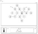
도1에 도시한 바와 같이, 컴퓨팅 기기(120)는 수신된 오브젝트 집합(110)에 따라 오브젝트 집합(110)에 대응되는 시각적 표현(130)을 제공할 수 있다. 예를 들면, 도1의 예시에서, 컴퓨팅 기기(120)는 오브젝트 집합(110)의 각 오브젝트를 나타내는 정보 및 각 오브젝트 사이 관계의 시각적 표현(130)을 생성할 수 있다. 도시한 시각적 표현은 예시적인 것일 뿐, 본 개시의 범위는 이러한 측면에서 한정되지 않음을 이해하여야 한다.As shown in FIG. 1 , the
아래, 도2 내지 도6을 참조하여 문제 응답 과정에 대해 더 상세하게 설명하고자 한다. 도2는 본 개시의 일부 실시예에 따른 오브젝트 집합의 시각적 표현을 제공하는 과정(200)의 흐름도를 도시한다. 과정(200)은 도1의 컴퓨팅 기기(120)에 의해 구현될 수 있다. 토론의 편의를 위해, 도1, 도3 내지 도6을 결부하여 과정(200)에 대하여 설명하고자 한다.Hereinafter, the problem response process will be described in more detail with reference to FIGS. 2 to 6 . 2 depicts a flow diagram of a
단계202에서, 컴퓨팅 기기(120)는 드로잉 영역 내에서 오브젝트 집합(110)의 제1 오브젝트의 제1 표시 정보를 제공하는 제1 위치를 결정한다. 일부 실시예에서, 오브젝트 집합(110)은 오브젝트 집합(110)의 하나 또는 복수의 오브젝트를 나타내는 오브젝트 정보를 포함할 수 있다. 예를 들면, 오브젝트 정보는 오브젝트 집합(110)의 각 오브젝트에 연관되는 메타데이터를 포함할 수 있는바, 당해 메타데이터는 예를 들어 오브젝트의 명칭, 역할, 오브젝트의 식별자 및 오브젝트에 연관되는 리소스 어드레스 등을 포함할 수 있다. 예를 들면, 하나의 오브젝트에 연관되는 오브젝트 정보는 이하의 형식으로 취합될 수 있다.In
{{
Src: 'static/image/1.jpeg',Src: 'static/image/1.jpeg',
Id: '1',Id: '1',
Role: '1',Role: '1',
Name: '장싼'Name: 'Jangsan'
}}
{{
Src: 'static/image/2.jpeg',Src: 'static/image/2.jpeg',
Id: '2',Id: '2',
Role: '0',Role: '0',
Name: '리쓰'Name: 'Lith'
}}
여기서, Src 필드는, 예를 들면, 당해 오브젝트의 이미지(picture)의 어드레스를 저장할 수 있고, Id 필드는 당해 오브젝트의 식별자를 나타낼 수 있고, Role 필드는 당해 오브젝트의 역할(예를 들면, 주연인지 여부)을 저장할 수 있고, Name 필드는 당해 오브젝트의 명칭을 저장할 수 있다.Here, the Src field may store, for example, an address of a picture of the object, the Id field may indicate an identifier of the object, and the Role field may indicate the role of the object (eg, whether it is the main character). or not), and the Name field may store the name of the object.
일부 실시예에서, 컴퓨팅 기기(120)는 또한 오브젝트 집합(110)의 각 오브젝트 사이 관계를 나타내는 오브젝트 관계 정보를 수신할 수 있다. 일부 실시예에서, 오브젝트 관계 정보는 오브젝트 집합에 저장될 수 있다. 일부 실시예에서, 컴퓨팅 기기(120)는 또한 저장 기기로부터 대응되는 오브젝트 관계 정보를 판독할 수 있다. 예를 들면, 오브젝트 관계 정보는 이하의 형식으로 취합될 수 있다.In some embodiments, the
{{
Source: '1',Source: '1',
Target: '2',Target: '2',
Relation: '친구'Relation: 'Friend'
}}
여기서, Source는 소스 오브젝트의 식별자를 표시하고, Target은 목표 오브젝트의 식별자를 표시하고, Relation은 소스 오브젝트와 목표 오브젝트 사이의 관계를 표시한다. 예를 들면, 당해 오브젝트 관계 정보는 식별자가 '1'인 오브젝트와 식별자가 '2'인 오브젝트가 친구 관계임을 표시한다. 위에서 주어진 오브젝트 정보 및 오브젝트 관계 정보는 단지 예시적인 것일 뿐, 임의의 적합한 방식으로 오브젝트 정보 및/또는 오브젝트 관계 정보를 취합할 수 있으며, 본 개시의 범위는 이러한 측면에서 한정되지 않음을 이해하여야 한다.Here, Source indicates the identifier of the source object, Target indicates the identifier of the target object, and Relation indicates the relationship between the source object and the target object. For example, the object relationship information indicates that an object having an identifier of '1' and an object having an identifier of '2' are friends. It should be understood that the object information and object relationship information given above are merely exemplary, and object information and/or object relationship information may be aggregated in any suitable manner, and the scope of the present disclosure is not limited in this respect.
일부 실시예에서, 오브젝트 집합(110)에 대한 시각적 표현을 제공하기 위하여, 컴퓨팅 기기(120)는 소정의 드로잉 영역을 설정할 수 있다. 일부 실시예에서, 드로잉 영역은 오브젝트 집합(110)의 시각적 표현을 나타내는 소정 크기의 캔버스일 수 있다. 도3은 본 개시의 실시예에 따른 소정 드로잉 영역을 설정하는 개략도(300)를 도시한다. 도3에 도시한 바와 같이, 컴퓨팅 기기(120)는 소정의 드로잉 영역(310)을 미리 설정할 수 있다.In some embodiments, in order to provide a visual representation of the object set 110 , the
일부 실시예에서, 도3에 도시한 바와 같이, 컴퓨팅 기기(120)는 또한 드로잉 영역(310)에서 복수의 소정의 위치를 결정할 수 있는바, 이러한 소정의 위치는 가능한 오브젝트의 시각적 표현을 제공할 수 있다. 일부 실시예에서, 복수의 소정의 위치는 행 또는 열에 따라 드로잉 영역(310)에 균일하게 분포되거나 규칙적으로 분포된다. 일부 실시예에서, 컴퓨팅 기기(120)는 사용자의 입력을 수신하여 이러한 소정의 위치의 바람직한 분포에 대하여 배치한다. 각 오브젝트의 시각적 표현이 제공될 수 있는 위치를 고정함으로써, 컴퓨팅 기기(120)는 오브젝트 집합(110)의 시각적 표현(130)이 규칙적이고 질서 있도록 보장할 수 있는바, 따라서 사용자가 시각적 표현(130)을 통하여 정보를 획득하는 효율을 향상시킨다. 또한, 이러한 취합 방식은 작은 스크린 기기에서의 표시에 더욱 적합하다.In some embodiments, as shown in Figure 3,
예를 들면, 도3에 도시한 바와 같이, 복수의 소정의 위치가 균일하게 분포되는바, 예를 들어 위치(312)에 인접하는 6개의 위치가 존재하는 경우, 이러한 위치는 위치(312) 주변에 정육각형으로 배열된다. 일부 실시예에서, 복수의 소정의 위치가 균일하게 분포될 수 있는바, 위치(312)에 인접하는 4개의 위치가 존재하는 경우, 이러한 위치는 위치(312) 주변에 정사각형으로 배열된다. 이러한 구체적인 분포는 단지 예시적인 것으로, 임의의 적합한 소정 위치 분포가 적용될 수 있는바, 본 개시의 범위는 이러한 측면에서 한정되지 않음을 이해하여야 한다.For example, as shown in FIG. 3 , a plurality of predetermined positions are uniformly distributed. For example, when six positions adjacent to the
일부 실시예에서, 드로잉 영역(310)에 아직 어떠한 오브젝트의 표시 정보도 제공되지 않은 경우, 컴퓨팅 기기(120)는 오브젝트 집합(110)의 메인 오브젝트를 획득하여 제1 오브젝트로 할 수 있다. 일부 실시예에서, 메인 오브젝트는 사용자한테 나타낼 오브젝트 집합(110)에서 미리 설정되는 핵심 오브젝트를 표시할 수 있다. 일부 실시예에서, 메인 오브젝트는 사용자의 입력에 응답하여 결정되는 사용자가 당시 흥미를 가지는 오브젝트일 수 있는바, 예를 들면, 컴퓨팅 기기(120)는 사용자에 의하여 입력되는 조회(예를 들면, 장싼)를 수신하여 메인 오브젝트를 '장싼'으로 결정할 수 있다. 예를 들면, 컴퓨팅 기기(120)는 오브젝트 집합(110)에서 Role 필드의 값이'1'인(즉, 역할이 '주역'인) 오브젝트를 획득하여 이를 제1 오브젝트로 할 수 있다.In some embodiments, when display information of any object is not yet provided in the
오브젝트 집합(110)의 메인 오브젝트(예를 들면, 역할이 '주역'인 오브젝트)에 있어서, 컴퓨팅 기기(120)는 복수의 소정 위치 중에서 자동으로 가운데의 위치를 선택하여, 메인 오브젝트를 제공하는 표시 정보로 할 수 있다. 예를 들면, 도3의 예시에서, 컴퓨팅 기기(120)는 위치(312)를 오브젝트 집합(110)의 제1 오브젝트의 제1 표시 정보를 제공하는 제1 위치로 결정할 수 있다.For the main object of the object set 110 (eg, an object whose role is 'main'), the
일부 실시예에서, 컴퓨팅 기기(120)는 오브젝트 정보에 따라 제1 오브젝트의 제1 표시 정보를 획득할 수 있다. 예를 들면, 컴퓨팅 기기(120)는 오브젝트의 명칭, 역할 및 ID 등 정보를 획득하고, 제1 위치(312)에서 이러한 정보를 제공할 수 있다. 일부 실시예에서, 컴퓨팅 기기(120)는 오브젝트 정보에 따라 제1 오브젝트에 연관되는 리소스 어드레스를 획득할 수 있는바, 예를 들어 'static/image/1.jpeg'와 같고, 컴퓨팅 기기(120)는 당해 어드레스를 액세스하여, 제1 오브젝트에 연관되는 이미지를 획득하여 제1 위치(312)에서 표시할 수 있다.In some embodiments, the
계속하여 도2를 참조하면, 단계204에서, 컴퓨팅 기기(120)는 드로잉 영역(310) 내의 복수의 소정 위치 중에서 제1 위치에 연관되는 사용 가능 위치를 결정한다. 계속하여, 도3의 예시에 있어서, 제1 위치(312)에서의 오브젝트의 표시가 완료된 후, 컴퓨팅 기기(120)는 제1 위치(312)에 연관되는 사용 가능 위치를 결정할 수 있다. 아래, 도4를 결부하여 단계204의 구체적인 과정을 설명하고자 하는바, 도4는 본 개시의 실시예에 따른 사용 가능 위치를 결정하는 과정(400)의 흐름도를 도시한다.Continuing to refer to FIG. 2 , in
단계402에서, 컴퓨팅 기기(120)가 제1 위치에 연관되는 제2 위치를 획득한다. 도5에 도시한 바와 같이, 컴퓨팅 기기(120)에 의하여 제1 위치(312)에서의 제1 표시 정보의 제공이 완료된 후, 컴퓨팅 기기(120)는 제1 위치(312)에 인접하는 제2 위치를 획득할 수 있다. 일부 실시예에서, 컴퓨팅 기기(120)는 각 소정의 위치에 상응한 식별자를 할당하고, 각 식별자가 인접한지에 관한 인접 정보를 저장할 수 있다. 도5에 도시한 바와 같이, 예를 들어 인접 정보에 따라, 컴퓨팅 기기(120)는 제1 위치(312)에 인접하는 제2 위치(512)를 획득할 수 있다.In
단계404에서, 컴퓨팅 기기(120)가 과거 드로잉 정보에 따라 제2 위치가 사용 가능한지 여부를 결정하는바, 과거 드로잉 정보는 복수의 소정 위치의 사용 상황을 나타낸다. 일부 실시예에서, 컴퓨팅 기기(120)는 복수의 소정 위치의 사용 상황을 나타내는 과거 드로잉 정보를 유지할 수 있다. 예를 들면, 컴퓨팅 기기(120)에 의하여 제1 위치(312)에서 제1 표시 정보가 제공된 후, 컴퓨팅 기기(120)는 과거 드로잉 정보에서 제1 위치(312)를 '사용됨'으로 표기할 수 있다.In
단계406에서, 제2 위치가 사용 가능한 것에 응답하여, 컴퓨팅 기기(120)는 제2 위치를 사용 가능 위치로 결정한다. 도5는 본 개시의 실시예에 따른 사용 가능 위치를 결정하는 개략도(500)를 도시한다. 도5의 예시에서, 컴퓨팅 기기(120)는 과거 드로잉 정보에 따라 제2 위치(512)를 사용 가능 위치로 결정할 수 있다.In
계속하여 도2를 참조하면, 단계206에서, 컴퓨팅 기기(120)는 오브젝트 집합에서 제1 오브젝트에 연관되는 제2 오브젝트를 결정한다. 일부 실시예에서, 컴퓨팅 기기(120)는 제1 오브젝트와 오브젝트 집합중의 기타 오브젝트 사이에 관계가 존재하는지 여부를 나타내는 오브젝트 관계 정보를 획득할 수 있다. 위에서 설명한 바와 같이, 일부 실시예에서, 오브젝트 집합(110)은 오브젝트 집합(110)의 각 오브젝트 사이 관계를 나타내는 오브젝트 관계 정보를 포함할 수 있다. 일부 실시예에서, 컴퓨팅 기기(120)는 오브젝트 관계 정보에 따라, 제1 오브젝트와 오브젝트 집합중의 기타 오브젝트 사이에 관계가 존재하는지 여부를 나타내는 관계 정보를 추출할 수 있다.Continuing to refer to FIG. 2 , in
다음, 컴퓨팅 기기(120)는 관계 정보에 따라, 오브젝트 집합에서 제1 오브젝트에 연관되는 제2 오브젝트를 선택할 수 있다. 일부 실시예에서, 예를 들어 컴퓨팅 기기(120)는 오브젝트 관계 정보 중의 'Source' 필드 및 'Target' 필드에 따라, 제1 오브젝트에 연관되는 제2 오브젝트를 결정할 수 있다. 예를 들면, 컴퓨팅 기기(120)는 오브젝트 정보에 따라 식별자가 '2'인 오브젝트가 제1 오브젝트에 연관되는 것임을 결정할 수 있다. 일부 실시예에서, 오브젝트 집합(110)의 각 오브젝트는 가중 정보가 미리 설정될 수 있는바, 제1 오브젝트에 연관되는 복수의 개체가 존재하는 경우, 컴퓨팅 기기(120)는 가중치 정보에 따라 순차적으로 가중치가 더 큰 오브젝트를 선택하여 표시할 제2 오브젝트로 한다. 이러한 방식에 따라, 컴퓨팅 기기(120)는 가중치가 더 큰 오브젝트가 우선으로 나타나도록 보장할 수 있다.Next, the
계속하여 도2를 참조하면, 단계208에서, 컴퓨팅 기기(120)는 사용 가능 위치에서 제2 오브젝트에 연관되는 제2 표시 정보를 제공한다. 일부 실시예에서, 컴퓨팅 기기(120)는 제2 오브젝트에 연관되는 오브젝트 정보에 따라, 제2 표시 정보를 획득할 수 있다. 일부 실시예에서, 상기 제2 표시 정보는 상기 제2 오브젝트를 나타내는 라벨, 이미지, 형상 및 색상 등 항목 중의 적어도 하나를 포함한다. 예를 들면, 일부 실시예에서, 컴퓨팅 기기(120)는 오브젝트 정보에 따라 제2 오브젝트의 명칭, 역할 및 ID 등 정보를 획득하여 이를 제2 표시 정보로 할 수 있다. 일부 실시예에서, 컴퓨팅 기기(120)는 제2 오브젝트에 연관되는 리소스 어드레스에 따라, 제2 표시 정보를 획득할 수 있다. 예를 들면, 컴퓨팅 기기(120)는 오브젝트 정보에 따라, 제2 오브젝트에 연관되는 리소스 어드레스를 획득할 수도 있는바, 예를 들어 'static/image/2.jpeg'와 같다. 컴퓨팅 기기(120)는 당해 어드레스에 액세스하여 제2 오브젝트에 연관되는 이미지를 획득하여 이를 제2 표시 정보로 할 수 있다.Continuing to refer to FIG. 2 , in
일부 실시예에서, 컴퓨팅 기기(120)는 사용 가능 위치(512)에서 획득되는 제2 표시 정보를 표시할 수 있다. 예를 들면, 컴퓨팅 기기(120)는 사용 가능 위치(512)에서 제2 오브젝트의 이미지를 표시할 수 있다. 일부 실시예에서, 제2 표시 정보는 아래의 제2 오브젝트를 나타내는 명칭(李四), 제2 오브젝트를 나타내는 이미지, 제2 오브젝트를 나타내는 형상 및 제2 오브젝트를 나타내는 색상 중의 임의의 하나를 포함한다. 일부 실시예에서, 부동한 형상 및/또는 부동한 색상은 제2 오브젝트의 특정된 역할에 연관될 수 있다.In some embodiments, the
일부 실시예에서, 컴퓨팅 기기(120)는 드로잉 영역(310)에서 제1 표시 정보와 제2 표시 정보를 연결하여, 제1 오브젝트와 제2 오브젝트 사이의 관계를 나타낼 수 있다. 일부 실시예에서, 컴퓨팅 기기(120)는 부동한 라인(line)에 의하여 부동한 관계 유형을 구분할 수 있는바, 예를 들면, 빨간색 라인으로 부부 관계를 나타낼 수 있고, 검은색 라인으로 친구 관계를 나타낼 수 있다. 일부 실시예에서, 컴퓨팅 기기(120)는 라인에 제1 오브젝트와 제2 오브젝트 사이의 관계를 나타내는 문자를 표시할 수도 있다.In some embodiments, the
일부 실시예에서, 제2 표시 정보가 제공된 것에 응답하여, 컴퓨팅 기기(120)는 과거 드로잉 정보를 업데이트하여, 사용 가능 위치(512)가 사용되었음을 나타낼 수 있는바, 따라서 다음번에 사용 가능 위치를 결정할 때, 위치(512)가 사용되었음을 알 수 있도록 하고, 이로써 중복되게 어느 한 위치에서 부동한 오브젝트의 표시 정보가 제공되는 것을 피할 수 있다.In some embodiments, in response to the second indication information being provided,
계속하여, 도5의 예시에 있어서, 컴퓨팅 기기(120)는 사용 가능 위치(512, 514, 516, 518, 520 및 522)를 순차적으로 결정하고, 오브젝트 집합에서 제1 오브젝트에 연관되는 오브젝트를 순차적으로 결정하고, 대응되는 사용 가능 위치에서 상응한 오브젝트의 표시 정보를 제공할 수 있다. 컴퓨팅 기기(120)는 모든 오브젝트에 대한 표시 정보의 제공이 완료될 때까지 반복적으로(iteratively) 단계202 내지 단계208를 수행할 수 있다.Continuing, in the example of FIG. 5 , the
도6은 본 개시의 실시예에 따른 예시적인 시각적 표현의 개략도(600)를 도시한다. 예를 들면, 오브젝트 집합(110)의 최종적인 시각적 표현은 시각적 표현(610)의 도시와 같다. 일부 실시예에서, 컴퓨팅 기기(110)는 드로잉 영역(310)과 상이한 표시 영역(620)에서 제1 오브젝트에 연관되는 추가 정보를 표시할 수 있다. 일부 실시예에서, 추가 정보는 제1 오브젝트에 연관되는 이미지 및/또는 영상 정보(622)를 포함할 수 있다. 일부 실시예에서, 추가 정보는 제1 오브젝트에 연관되는 문자 정보(624)를 더 포함할 수 있는바, 예를 들면 제1 오브젝트에 대한 더욱 상세한 소개에 관한 것일 수 있다. 이러한 추가적인 표시 정보를 제공함으로써, 컴퓨팅 기기(120)는 사용자가 더욱 편리하고 신속하게 사용자가 관심을 가지는 오브젝트의 상세 정보를 획득하도록 할 수 있다.6 shows a schematic diagram 600 of an exemplary visual representation in accordance with an embodiment of the present disclosure. For example, the final visual representation of the object set 110 is as shown in the
상술한 방법에 따라, 규칙적이고 질서 있는, 표시 정보를 제공하는 소정 위치를 설정함으로써, 컴퓨팅 기기(120)는 제공되는 시각적 표현이 규칙적인 방식으로 나타나도록 보장할 수 있는바, 따라서 종래의 힘 방향 그래프에 따른 경우에 있어서 난잡하고 무질서한 결함을 극복함으로써, 오브젝트 집합의 정보가 더욱 선명하고 직관적이게 나타날 수 있도록 하여, 사용자가 정보를 획득하는 효율을 향상시킨다. 또한, 이러한 취합 방식은 이동 단말 기기와 같은 작은 스크린 기기의 표시에 더욱 적합하다.According to the method described above, by establishing a predetermined position for providing display information in a regular and orderly manner, the
일부 실시예에서, 컴퓨팅 기기(120)는 또한 데이터 라벨(610)의 임의의 표시 정보에 대한 선택을 수신할 수 있다. 일부 실시예에서, 특정 개체(예를 들면, 제2 오브젝트)에 연관되는 표시 정보에 대한 선택이 수신된 것에 응답하여, 컴퓨팅 기기(120)는 당해 선택에 따라 제2 오브젝트를 메인 오브젝트로 하는 새로운 시각적 표현을 생성할 수 있다. 일부 실시예에서, 컴퓨팅 기기(120)는 제2 표시 정보(612)가 선택된 것이 결정된 것에 응답하여, 제2 오브젝트에 연관되는 추가 정보를 제공할 수 있다. 일부 실시예에서, 컴퓨팅 기기(120)는 당해 선택에 따라 제2 표시 정보의 외관을 변경시킬 수 있다. 일부 실시예에서, 컴퓨팅 기기(120)는 선택에 응답하여 제2 표시 정보를 강조할 수 있는바, 예를 들면, 제2 표시 정보를 확대하는 것, 제2 표시 정보의 색상을 변경하는 것 등이 있다. 이러한 방식에 따라, 사용자는 흥미를 가지는 기타 오브젝트로 신속하게 절환할 수 있고 당해 오브젝트에 대한 더욱 상세한 정보를 획득할 수 있다.In some embodiments,
도7은 본 개시의 실시예에 따른 오브젝트 집합의 시각적 표현을 제공하는 장치(700)의 블록도를 도시한다. 장치(700)는 도1의 컴퓨팅 기기(120)에 포함될 수도 있고, 또는 컴퓨팅 기기(120)로 구현될 수도 있다 . 도7에 도시한 바와 같이, 장치(700)는 드로잉 영역 내에서 오브젝트 집합중의 제1 오브젝트의 제1 표시 정보를 제공하는 제1 위치를 결정하도록 구성되는 제1 위치 결정 모듈(710)을 포함한다. 장치(700)는 드로잉 영역 내의 복수의 소정 위치 중에서 제1 위치에 연관되는 사용 가능 위치를 결정하도록 구성되는 사용 가능 위치 결정 모듈(720)을 더 포함한다. 장치(700)는 오브젝트 집합에서 제1 오브젝트에 연관되는 제2 오브젝트를 결정하도록 구성되는 제2 오브젝트 결정 모듈(730)을 더 포함한다. 또한, 장치(700)는 사용 가능 위치에서 제2 오브젝트의 제2 표시 정보를 제공하도록 구성되는 제공 모듈(740)을 더 포함한다.7 shows a block diagram of an
일부 실시예에서, 복수의 소정의 위치는 행 또는 열에 따라 드로잉 영역에 균일하게 분포되거나 규칙적으로 분포된다.In some embodiments, the plurality of predetermined positions are uniformly or regularly distributed in the drawing area according to rows or columns.
일부 실시예에서, 사용 가능 위치 결정 모듈(720)은, 제1 위치에 연관되는 제2 위치를 획득하도록 구성되는 제2 위치 획득 모듈; 과거 드로잉 정보에 따라 제2 위치가 사용 가능한지 여부를 결정하도록 구성되는 사용 가능 상태 결정 모듈 - 과거 드로잉 정보는 복수의 소정 위치의 사용 상황을 나타냄 - ; 및 제2 위치가 사용 가능한 것에 응답하여, 제2 위치를 사용 가능 위치로 결정하도록 구성되는 제2 사용 가능 위치 결정 모듈; 을 포함한다.In some embodiments, the usable
일부 실시예에서, 장치(700)는, 과거 드로잉 정보를 업데이트하여 사용 가능 위치가 사용되었음을 나타내도록 구성되는 업데이트 모듈을 더 포함한다.In some embodiments, the
일부 실시예에서, 제2 오브젝트 결정 모듈(730)은, 제1 오브젝트와 오브젝트 집합중의 기타 오브젝트 사이에 관계가 존재하는지 여부를 나타내는 관계 정보를 획득하도록 구성되는 관계 정보 획득 모듈; 및 관계 정보에 따라 오브젝트 집합에서 제1 오브젝트에 연관되는 제2 오브젝트를 선택하도록 구성되는 제2 오브젝트 선택 모듈; 을 포함한다.In some embodiments, the second
일부 실시예에서, 제공 모듈(740)은, 제2 오브젝트에 연관되는 리소스 어드레스에 따라, 제2 표시 정보를 획득하도록 구성되는 제2 표시 정보 획득 모듈; 및 사용 가능 위치에서, 획득되는 제2 표시 정보를 표시하도록 구성되는 제1 표시 모듈; 을 포함한다.In some embodiments, the providing
일부 실시예에서, 제2 표시 정보는 제2 오브젝트를 나타내는 라벨, 이미지, 형상 및 색상 등 항목 중의 적어도 하나를 포함한다In some embodiments, the second display information includes at least one of a label indicating the second object, an image, a shape, and a color.
일부 실시예에서, 장치(700)는, 제2 표시 정보가 선택되었음이 결정된 것에 응답하여, 제2 오브젝트에 연관되는 추가 정보를 표시하도록 구성되는 제2 표시 모듈을 더 포함한다.In some embodiments, the
도8은 본 개시의 실시예를 구현하기 위한 예시 기기(800)의 개략적 블록도를 도시한다. 기기(800)는 도1의 컴퓨팅 기기(120)를 구현할 수 있다. 도시한 바와 같이, 기기(800)는 중앙 프로세서 유닛(CPU)(801)을 포함하는바, 이는 읽기 전용 메모리(ROM)(802)에 저장된 컴퓨터 프로그램 명령어 또는 저장 유닛(808)으로부터 랜덤 액세스 메모리(RAM)(803)로 로딩된 컴퓨터 프로그램 명령어에 따라 여러 가지 적당한 동작과 처리를 실행할 수 있다. RAM(803)에는 기기(800) 조작에 필요한 여러 가지 프로그램과 데이터가 저장될 수도 있다. CPU(801), ROM(802) 및 RAM(803)는 버스(804)를 통하여 서로 연결된다. 입력/출력(I/O) 인터페이스(805)도 버스(804)에 연결된다.8 shows a schematic block diagram of an
기기(800) 중의 복수의 부품은 I/O 인터페이스(805)에 연결되는바, 입력 유닛(806), 예를 들어 키보드, 마우스 등; 출력 유닛(807), 예를 들어 여러 가지 유형의 표시, 스피커 등; 저장 유닛(808), 예를 들어 자기 디스크, 광디스크 등; 및 통신 유닛(809), 예를 들어 네트워크 카드, 모뎀, 무선 통신 송수신기 등이 포함된다. 통신 유닛(809)은 기기(800)가 인터넷과 같은 컴퓨터 네트워크 및/또는 여러 가지 전기 통신 네트워크를 통하여 기타 기기와 정보/데이터를 교환하도록 허용한다. A plurality of components of the
프로세서 유닛(801)은 전술에서 설명된 각각의 방법과 처리를 실행하는바, 예를 들어 과정(200 및/또는 400)이다. 예를 들어, 일부 실시예에서, 과정(200 및/또는 400)은 컴퓨터 소프트웨어 프로그램으로 구현될 수 있는바, 이는 기계 판독 가능 매체, 예를 들어 저장 유닛(808)에 유형적으로 포함된다. 일부 실시예에서, 컴퓨터 프로그램의 일부 또는 전부가 ROM(802) 및/또는 통신 유닛(809)을 통하여 기기(800)에 로딩 및/또는 설정될 수 있다. 컴퓨터 프로그램이 RAM(803)에 로딩되어 CPU(801)에 의하여 실행될 시, 전술에서 설명된 과정(200 및/또는 400)의 하나 또는 복수의 단계를 실행할 수 있다. 대안적으로, 기타 실시예에서, CPU(801)는 기타 임의의 적당한 방식을 통해(예를 들어, 펌웨어의 도움으로) 과정(200 및/또는 400)을 실행하도록 구성될 수 있다.The
본 명세서에서, 이상에서 설명된 기능은 적어도 부분적으로 하나 또는 복수의 하드웨어 논리 부품에 의해 실행될 수 있다. 예를 들어, 무제한적으로, 사용 가능한 시범 유형의 하드웨어 논리 부품은 필드 프로그램 가능 게이트 어레이(FPGA), 주문형 반도체(ASIC), 특정 용도 표준 제품(ASSP), 시스템 온 칩(SOC), 복합 프로그래머블 논리 소자(CPLD), 등을 포함한다.In this specification, the functions described above may be at least partially executed by one or a plurality of hardware logic components. For example, an unlimited number of trial types of hardware logic components available include field programmable gate arrays (FPGAs), application specific integrated circuits (ASICs), application-specific standard products (ASSPs), system-on-chips (SOCs), complex programmable logic devices (CPLDs), and the like.
본 개시의 방법을 구현하기 위한 프로그램 코드는 하나 또는 복수의 프로그래밍 언어의 임의의 조합을 적용하여 작성할 수 있다. 이러한 프로그램 코드는 범용 컴퓨터, 전용 컴퓨터 또는 기타 프로그램 가능 데이터 처리 장치의 프로세서 또는 제어기에 제공되어 프로그램 코드가 프로세서 또는 제어기에 의해 실행될 시 흐름도 및/또는 블록도에 규정한 기능/조작이 구현되도록 할 수 있다. 프로그램 코드는 기계에서 전부 실행되거나, 기계에서 일부 실행되거나, 독립적인 소프트웨어 패키지로서 일부는 기계에서 실행되고, 일부는 원격 기계에서 실행되거나, 혹은 원격 기계 또는 서버에서 전부 실행될 수 있다.Program code for implementing the method of the present disclosure may be written by applying any combination of one or a plurality of programming languages. Such program code may be provided to the processor or controller of a general-purpose computer, dedicated computer, or other programmable data processing device so that, when the program code is executed by the processor or controller, the functions/operations specified in the flowcharts and/or block diagrams are implemented. there is. The program code may run entirely on the machine, partly on the machine, or as a standalone software package, partly running on the machine, partly running on the remote machine, or entirely running on the remote machine or server.
본 개시의 전반 서술에서, 기계 판독 가능 매체는 유형의 매체일 수 있는바, 이는, 명령어 실행 시스템, 장치 또는 기기에 사용하기 위한, 또는 명령어 실행 시스템, 장치 또는 기기와 결합하여 사용하기 위한 프로그램을 포함 또는 저장할 수 있다. 기계 판독 가능 매체는 기계 판독 가능 신호 매체 또는 기계 판독 가능 저장 매체일 수 있다. 기계 판독 가능 매체는 전자의, 자성의, 광학의, 전자기의, 적외선의 또는 반도체의 시스템, 장치 또는 기기, 또는 상술한 내용의 임의의 적합한 조합을 포함할 수 있으나, 이에 한정되지 않는다. 기계 판독 가능 저장 매체의 더 구체적인 예시는, 하나 또는 복수의 선에 따른 전기 연결, 휴대형 컴퓨터 디스크, 하드 디스크, 랜덤 액세스 메모리(RAM), 읽기 전용 메모리(ROM), 소거 및 프로그램 가능 읽기 전용 메모리(EPROM 또는 플래시 메모리), 광섬유, 휴대용 콤팩트 디스크 읽기 전용 메모리(CD-ROM), 광학 저장 기기, 자기 저장 기기, 또는 상술한 내용의 임의의 적합한 조합을 포함한다.In the overall description of this disclosure, a machine-readable medium may be a tangible medium, which may contain a program for use in, or in combination with, an instruction execution system, apparatus, or apparatus. can be included or stored. The machine-readable medium may be a machine-readable signal medium or a machine-readable storage medium. A machine-readable medium may include, but is not limited to, an electronic, magnetic, optical, electromagnetic, infrared or semiconductor system, apparatus or apparatus, or any suitable combination of the foregoing. More specific examples of machine-readable storage media include: an electrical connection along one or multiple wires, a portable computer disk, a hard disk, a random access memory (RAM), a read-only memory (ROM), an erasable and programmable read-only memory ( EPROM or flash memory), optical fiber, portable compact disk read-only memory (CD-ROM), optical storage devices, magnetic storage devices, or any suitable combination of the foregoing.
이 외에, 비록 각 조작을 묘사함에 있어서 특정 순서를 적용하였지만, 이러한 조작이 도시된 특정 순서로 또는 순차적 순서로 실행되어야 하거나, 또는 모든 도시한 조작이 실행되어야 하는 것으로, 이로써 기대하는 결과를 취득하기 위한 것임을 이해하여야 한다. 일정한 환경에서는, 다중 태스크 및 병렬 처리가 유익할 수 있다. 마찬가지로, 비록 위의 서술에는 약간의 구체 구현 디테일이 포함되지만, 이러한 것은 본 개시의 범위에 대한 제한으로 해석되어서는 안된다. 단독의 실시예의 전반 서술에서 설명되는 어떤 특징 또한, 조합 가능하게 하나의 구현에 구현될 수 있다. 반대로, 하나의 구현의 전반 서술에서 설명되는 여러 가지 특징도 단독으로 또는 임의의 적합한 서브조합의 방식으로 복수의 실시예에 구현될 수 있다.In addition, although a specific order is applied in depicting each operation, such operations must be performed in the specific order shown or sequential order, or all illustrated operations must be performed, thereby obtaining the expected result. It should be understood that this is for In certain circumstances, multiple tasks and parallel processing can be beneficial. Likewise, although the above description contains some specific implementation details, these should not be construed as limitations on the scope of the present disclosure. Any features that are described in the overall description of a single embodiment may also be implemented in one implementation in a combinatorial manner. Conversely, various features that are described in the general description of an implementation may also be implemented in multiple embodiments, either alone or in any suitable subcombination manner.
비록 이미 구조적 특징 및/또는 방법론적 동작에 특정된 언어를 적용하여 본 주제에 대해 설명하였지만, 첨부된 특허청구범위가 한정하는 주제는 위에서 설명한 특정 특징 또는 동작에 한정되는 것이 아님을 이해하여야 한다. 반대로, 위에서 설명한 특정 특징 및 동작은 단지 특허청구범위의 예시 형식을 구현하는 것일 뿐이다.Although the subject matter has already been described using language specific to structural features and/or methodological acts, it is to be understood that the subject matter defined by the appended claims is not limited to the specific features or acts described above. Conversely, the specific features and acts described above merely implement the example forms of the claims.
Claims (18)
Translated fromKorean드로잉 영역 내에서 오브젝트 집합중의 제1 오브젝트의 제1 표시 정보를 제공하는 제1 위치를 결정하는 단계;
상기 드로잉 영역 내의 복수의 소정 위치 중에서 상기 제1 위치에 연관되는 사용 가능 위치를 결정하는 단계;
상기 오브젝트 집합에서 상기 제1 오브젝트에 연관되는 제2 오브젝트를 결정하는 단계; 및
상기 사용 가능 위치에서 상기 제2 오브젝트의 제2 표시 정보를 제공하는 단계; 를 포함하는 것,
을 특징으로 하고,
상기 제1 위치에 연관되는 사용 가능 위치를 결정하는 단계는,
상기 제1 위치에 연관되는 제2 위치를 획득하는 단계;
과거 드로잉 정보에 따라 상기 제2 위치가 사용 가능한지 여부를 결정하는 단계 - 상기 과거 드로잉 정보는 상기 복수의 소정 위치의 사용 상황을 나타냄 - ; 및
상기 제2 위치가 사용 가능한 것에 응답하여, 상기 제2 위치를 상기 사용 가능 위치로 결정하는 단계; 를 포함하는 것,
을 특징으로 하는 오브젝트 집합의 시각적 표현을 제공하는 방법.A method for providing a visual representation of a set of objects, comprising:
determining a first position in the drawing area that provides first display information of a first object in the set of objects;
determining an available location associated with the first location from among a plurality of predetermined locations within the drawing area;
determining a second object associated with the first object in the object set; and
providing second display information of the second object at the available location; comprising,
characterized by,
Determining an available location associated with the first location includes:
obtaining a second location associated with the first location;
determining whether the second location is usable according to past drawing information, wherein the past drawing information indicates a usage situation of the plurality of predetermined locations; and
in response to the second location being available, determining the second location as the available location; comprising,
A method of providing a visual representation of a set of objects characterized by
상기 복수의 소정의 위치는 행 또는 열에 따라 상기 드로잉 영역에 균일하게 분포되거나 규칙적으로 분포되는 것,
을 특징으로 하는 오브젝트 집합의 시각적 표현을 제공하는 방법.According to claim 1,
the plurality of predetermined positions are uniformly or regularly distributed in the drawing area according to rows or columns;
A method of providing a visual representation of a set of objects characterized by
상기 과거 드로잉 정보를 업데이트하여 상기 사용 가능 위치가 사용되었음을 나타내는 단계를 더 포함하는 것,
을 특징으로 하는 오브젝트 집합의 시각적 표현을 제공하는 방법.According to claim 1,
further comprising updating the past drawing information to indicate that the available location has been used;
A method of providing a visual representation of a set of objects characterized by
상기 제2 오브젝트를 결정하는 단계는,
상기 제1 오브젝트와 상기 오브젝트 집합중의 기타 오브젝트 사이에 관계가 존재하는지 여부를 나타내는 관계 정보를 획득하는 단계; 및
상기 관계 정보에 따라, 상기 오브젝트 집합에서 상기 제1 오브젝트에 연관되는 상기 제2 오브젝트를 선택하는 단계; 를 포함하는 것,
을 특징으로 하는 오브젝트 집합의 시각적 표현을 제공하는 방법.According to claim 1,
The step of determining the second object comprises:
obtaining relationship information indicating whether a relationship exists between the first object and other objects in the set of objects; and
selecting the second object associated with the first object from the object set according to the relationship information; comprising,
A method of providing a visual representation of a set of objects characterized by
상기 제2 표시 정보를 제공하는 단계는,
상기 제2 오브젝트에 연관되는 리소스 어드레스에 따라, 상기 제2 표시 정보를 획득하는 단계; 및
상기 사용 가능 위치에서, 획득된 상기 제2 표시 정보를 표시하는 단계; 를 포함하는 것,
을 특징으로 하는 오브젝트 집합의 시각적 표현을 제공하는 방법.According to claim 1,
The step of providing the second display information comprises:
obtaining the second indication information according to a resource address associated with the second object; and
displaying the obtained second indication information in the available location; comprising,
A method of providing a visual representation of a set of objects characterized by
상기 제2 표시 정보는 상기 제2 오브젝트를 나타내기 위한 라벨, 이미지, 형상 및 색상 중 적어도 하나를 포함하는 것,
을 특징으로 하는 오브젝트 집합의 시각적 표현을 제공하는 방법.According to claim 1,
The second display information includes at least one of a label, an image, a shape, and a color for indicating the second object;
A method of providing a visual representation of a set of objects characterized by
상기 제2 표시 정보가 선택된 것이 결정된 것에 응답하여, 상기 제2 오브젝트에 연관되는 추가 정보를 제공하는 단계를 더 포함하는 것,
을 특징으로 하는 오브젝트 집합의 시각적 표현을 제공하는 방법.According to claim 1,
in response to determining that the second indication information is selected, further comprising providing additional information associated with the second object;
A method of providing a visual representation of a set of objects characterized by
드로잉 영역 내에서 오브젝트 집합중의 제1 오브젝트의 제1 표시 정보를 제공하는 제1 위치를 결정하도록 구성되는 제1 위치 결정 모듈;
상기 드로잉 영역 내의 복수의 소정 위치 중에서 상기 제1 위치에 연관되는 사용 가능 위치를 결정하도록 구성되는 사용 가능 위치 결정 모듈;
상기 오브젝트 집합에서 상기 제1 오브젝트에 연관되는 제2 오브젝트를 결정하도록 구성되는 제2 오브젝트 결정 모듈; 및
상기 사용 가능 위치에서 상기 제2 오브젝트의 제2 표시 정보를 제공하도록 구성되는 제공 모듈; 을 포함하는 것,
을 특징으로 하고,
상기 사용 가능 위치 결정 모듈은,
상기 제1 위치에 연관되는 제2 위치를 획득하도록 구성되는 제2 위치 획득 모듈;
과거 드로잉 정보에 따라 상기 제2 위치가 사용 가능한지 여부를 결정하도록 구성되는 사용 가능 상태 결정 모듈 - 상기 과거 드로잉 정보는 상기 복수의 소정 위치의 사용 상황을 나타냄 - ; 및
상기 제2 위치가 사용 가능한 것에 응답하여, 상기 제2 위치를 상기 사용 가능 위치로 결정하도록 구성되는 제2 사용 가능 위치 결정 모듈; 을 포함하는 것,
을 특징으로 하는 오브젝트 집합의 시각적 표현을 제공하는 장치.An apparatus for providing a visual representation of a set of objects, comprising:
a first position determining module, configured to determine a first position providing first display information of a first object in the set of objects within the drawing area;
an available location determining module configured to determine an available location associated with the first location from among a plurality of predetermined locations within the drawing area;
a second object determining module, configured to determine a second object associated with the first object in the object set; and
a providing module, configured to provide second indication information of the second object in the usable location; comprising,
characterized by,
The usable positioning module,
a second location obtaining module, configured to obtain a second location associated with the first location;
an availability status determining module, configured to determine whether the second location is usable according to past drawing information, wherein the past drawing information indicates usage status of the plurality of predetermined locations; and
a second available location determining module, configured to determine the second location as the available location in response to the second location being available; comprising,
A device that provides a visual representation of a set of objects characterized by
상기 복수의 소정의 위치는 행 또는 열에 따라 상기 드로잉 영역에 균일하게 분포되거나 규칙적으로 분포되는 것,
을 특징으로 하는 오브젝트 집합의 시각적 표현을 제공하는 장치.10. The method of claim 9,
the plurality of predetermined positions are uniformly or regularly distributed in the drawing area according to rows or columns;
A device that provides a visual representation of a set of objects characterized by
상기 과거 드로잉 정보를 업데이트하여 상기 사용 가능 위치가 사용되었음을 나타내도록 구성되는 업데이트 모듈을 더 포함하는 것,
을 특징으로 하는 오브젝트 집합의 시각적 표현을 제공하는 장치.10. The method of claim 9,
an update module, configured to update the past drawing information to indicate that the available location has been used;
A device that provides a visual representation of a set of objects characterized by
상기 제2 오브젝트 결정 모듈은,
상기 제1 오브젝트와 상기 오브젝트 집합중의 기타 오브젝트 사이에 관계가 존재하는지 여부를 나타내는 관계 정보를 획득하도록 구성되는 관계 정보 획득 모듈; 및
상기 관계 정보에 따라, 상기 오브젝트 집합에서 상기 제1 오브젝트에 연관되는 상기 제2 오브젝트를 선택하도록 구성되는 제2 오브젝트 선택 모듈; 을 포함하는 것,
을 특징으로 하는 오브젝트 집합의 시각적 표현을 제공하는 장치.10. The method of claim 9,
The second object determination module,
a relationship information obtaining module, configured to obtain relationship information indicating whether a relationship exists between the first object and another object in the set of objects; and
a second object selection module, configured to select the second object associated with the first object from the object set according to the relationship information; comprising,
A device that provides a visual representation of a set of objects characterized by
상기 제공 모듈은,
상기 제2 오브젝트에 연관되는 리소스 어드레스에 따라, 상기 제2 표시 정보를 획득하도록 구성되는 제2 표시 정보 획득 모듈; 및
상기 사용 가능 위치에서, 획득된 상기 제2 표시 정보를 표시하도록 구성되는 제1 표시 모듈; 을 포함하는 것,
을 특징으로 하는 오브젝트 집합의 시각적 표현을 제공하는 장치.10. The method of claim 9,
The providing module is
a second indication information obtaining module, configured to obtain the second indication information according to the resource address associated with the second object; and
a first display module, configured to display the obtained second display information in the usable position; comprising,
A device that provides a visual representation of a set of objects characterized by
상기 제2 표시 정보는 상기 제2 오브젝트를 나타내기 위한 라벨, 이미지, 형상 및 색상 중 적어도 하나를 포함하는것,
을 특징으로 하는 오브젝트 집합의 시각적 표현을 제공하는 장치.10. The method of claim 9,
The second display information includes at least one of a label, an image, a shape, and a color for indicating the second object;
A device that provides a visual representation of a set of objects characterized by
상기 제2 표시 정보가 선택된 것이 결정된 것에 응답하여, 상기 제2 오브젝트에 연관되는 추가 정보를 표시하도록 구성되는 제2 표시 모듈을 더 포함하는 것,
을 특징으로 하는 오브젝트 집합의 시각적 표현을 제공하는 장치.10. The method of claim 9,
in response to determining that the second display information is selected, further comprising a second display module, configured to display additional information associated with the second object;
A device that provides a visual representation of a set of objects characterized by
하나 또는 복수의 프로세서; 및
하나 또는 복수의 프로그램을 저장하기 위한 메모리; 를 포함하고,
상기 하나 또는 복수의 프로그램이 상기 하나 또는 복수의 프로세서에 의해 실행될 경우, 상기 전자 기기가 제1항, 제2항 및 제4항 내지 제8항 중 어느 한 항의 방법을 구현하는 것,
을 특징으로 하는 전자 기기.In an electronic device,
one or more processors; and
a memory for storing one or a plurality of programs; including,
When the one or more programs are executed by the one or more processors, the electronic device implements the method of any one of claims 1, 2, and 4 to 8,
Electronic device characterized in that.
상기 프로그램이 프로세서에 의해 실행될 경우, 제1항, 제2항 및 제4항 내지 제8항 중 어느 한 항의 방법이 구현되는 것,
을 특징으로 하는 컴퓨터 판독가능 저장 매체.In a computer-readable storage medium storing a computer program,
When the program is executed by a processor, the method of any one of claims 1, 2 and 4 to 8 is implemented,
A computer-readable storage medium comprising a.
Applications Claiming Priority (2)
| Application Number | Priority Date | Filing Date | Title |
|---|---|---|---|
| CN201910087406.0ACN109815299A (en) | 2019-01-29 | 2019-01-29 | Method, apparatus, device, and storage medium for providing a visual representation of a set of objects |
| CN201910087406.0 | 2019-01-29 |
Publications (2)
| Publication Number | Publication Date |
|---|---|
| KR20200094637A KR20200094637A (en) | 2020-08-07 |
| KR102282284B1true KR102282284B1 (en) | 2021-07-27 |
Family
ID=66605706
Family Applications (1)
| Application Number | Title | Priority Date | Filing Date |
|---|---|---|---|
| KR1020200000261AActiveKR102282284B1 (en) | 2019-01-29 | 2020-01-02 | Method, apparatus, device, and storage medium for providing visual representation of set of objects |
Country Status (5)
| Country | Link |
|---|---|
| US (1) | US11410333B2 (en) |
| EP (1) | EP3690675A1 (en) |
| JP (1) | JP6872047B2 (en) |
| KR (1) | KR102282284B1 (en) |
| CN (1) | CN109815299A (en) |
Families Citing this family (2)
| Publication number | Priority date | Publication date | Assignee | Title |
|---|---|---|---|---|
| CN111743574B (en)* | 2020-07-12 | 2023-04-07 | 西北工业大学 | Method for constructing knowledge graph of breast cancer ultrasonic image high confidence entity relationship |
| CN115630698B (en)* | 2022-12-08 | 2023-04-11 | 国家电网有限公司客户服务中心 | Knowledge map visualization method, device and electronic equipment based on force-guided graph |
Citations (2)
| Publication number | Priority date | Publication date | Assignee | Title |
|---|---|---|---|---|
| US20100058213A1 (en)* | 2008-08-28 | 2010-03-04 | Kabushiki Kaisha Toshiba | Display controlling apparatus and display controlling method |
| JP2010176204A (en)* | 2009-01-27 | 2010-08-12 | Sony Corp | Apparatus, method and program for processing information |
Family Cites Families (19)
| Publication number | Priority date | Publication date | Assignee | Title |
|---|---|---|---|---|
| US5729704A (en)* | 1993-07-21 | 1998-03-17 | Xerox Corporation | User-directed method for operating on an object-based model data structure through a second contextual image |
| JP2007149061A (en)* | 2005-10-31 | 2007-06-14 | Seiko Epson Corp | Layout system, layout program, and layout method |
| WO2007121557A1 (en)* | 2006-04-21 | 2007-11-01 | Anand Agarawala | System for organizing and visualizing display objects |
| US20090210820A1 (en)* | 2006-05-11 | 2009-08-20 | Takao Adachi | Display object layout changing device |
| JP4891740B2 (en)* | 2006-11-22 | 2012-03-07 | 株式会社日立製作所 | Content search apparatus and content search method |
| US20090128507A1 (en)* | 2007-09-27 | 2009-05-21 | Takeshi Hoshino | Display method of information display device |
| CN102568025B (en)* | 2010-12-20 | 2013-09-04 | 福建星网视易信息系统有限公司 | Method for ensuring 3D (three-dimensional) objects to move without being overlapped in display and display system |
| US9552376B2 (en)* | 2011-06-09 | 2017-01-24 | MemoryWeb, LLC | Method and apparatus for managing digital files |
| CA2839158A1 (en)* | 2011-06-13 | 2012-12-20 | Angiometrix Corporation | Multifunctional guidewire assemblies and system for analyzing anatomical and functional parameters |
| US20130268373A1 (en)* | 2012-04-04 | 2013-10-10 | Linkedln Corporation | Methods and systems for presenting personalized advertisements |
| CN103647754B (en)* | 2013-11-19 | 2017-03-29 | 广州杰赛科技股份有限公司 | The method for drafting and device of topological diagram in cloud computing |
| EP3114617A4 (en)* | 2014-03-05 | 2017-07-26 | Ayasdi Inc. | Systems and methods for capture of relationships within information |
| US9934424B2 (en)* | 2015-10-05 | 2018-04-03 | International Business Machines Corporation | Automated relationship categorizer and visualizer |
| CN107622792B (en)* | 2017-08-30 | 2021-12-31 | 东软医疗系统股份有限公司 | Medical image display method and display equipment |
| CN107992522B (en)* | 2017-11-06 | 2021-09-28 | 腾讯科技(深圳)有限公司 | Image processing method and device and terminal equipment |
| CN108170397A (en)* | 2018-01-19 | 2018-06-15 | 广州视源电子科技股份有限公司 | data display method, device, equipment and storage medium |
| CN109086315B (en)* | 2018-06-27 | 2021-07-20 | 创新先进技术有限公司 | ER graph layout method and device |
| CN109271525A (en)* | 2018-08-08 | 2019-01-25 | 北京百度网讯科技有限公司 | For generating the method, apparatus, equipment and computer readable storage medium of knowledge mapping |
| US20200183980A1 (en)* | 2018-12-10 | 2020-06-11 | James R. Barkow | System and method for creating a family graph in digital form |
- 2019
- 2019-01-29CNCN201910087406.0Apatent/CN109815299A/enactivePending
- 2020
- 2020-01-02KRKR1020200000261Apatent/KR102282284B1/enactiveActive
- 2020-01-07JPJP2020000667Apatent/JP6872047B2/enactiveActive
- 2020-01-13EPEP20151357.9Apatent/EP3690675A1/ennot_activeCeased
- 2020-01-23USUS16/750,403patent/US11410333B2/enactiveActive
Patent Citations (2)
| Publication number | Priority date | Publication date | Assignee | Title |
|---|---|---|---|---|
| US20100058213A1 (en)* | 2008-08-28 | 2010-03-04 | Kabushiki Kaisha Toshiba | Display controlling apparatus and display controlling method |
| JP2010176204A (en)* | 2009-01-27 | 2010-08-12 | Sony Corp | Apparatus, method and program for processing information |
Also Published As
| Publication number | Publication date |
|---|---|
| US20200242803A1 (en) | 2020-07-30 |
| KR20200094637A (en) | 2020-08-07 |
| JP6872047B2 (en) | 2021-05-19 |
| US11410333B2 (en) | 2022-08-09 |
| EP3690675A1 (en) | 2020-08-05 |
| JP2020123323A (en) | 2020-08-13 |
| CN109815299A (en) | 2019-05-28 |
Similar Documents
| Publication | Publication Date | Title |
|---|---|---|
| KR102291674B1 (en) | Method and apparatus for generating knowledge graph, device and computer readable storage medium | |
| TWI531953B (en) | Temporary formatting and charting of selected data | |
| KR101811464B1 (en) | Spin control user interface for selecting options | |
| US9846708B2 (en) | Searching of images based upon visual similarity | |
| US9128595B2 (en) | Managing data content on a computing device | |
| US11281742B2 (en) | Interactive and selective coloring of digital vector glyphs | |
| CN108536467B (en) | Code positioning processing method, device, terminal device and storage medium | |
| CN113971309B (en) | Model generation method, device, computer equipment and storage medium | |
| US20170344229A1 (en) | Selection control method, selection control device, and recording medium | |
| US10109094B2 (en) | Interface to index and display geospatial data | |
| CN112100795A (en) | Method and device for comparing computer aided design drawings | |
| KR102282284B1 (en) | Method, apparatus, device, and storage medium for providing visual representation of set of objects | |
| CN117991944A (en) | Binding data to a graphical object using a visual indicator | |
| US11250058B2 (en) | Providing an easily navigable visual representation of a graph | |
| CN108700980A (en) | Prompt information display method and system | |
| US20170357412A1 (en) | Data creating device, data creating method, and data creating program | |
| US10846061B2 (en) | Development environment for real-time application development | |
| CN111144090A (en) | File comparison method and device, electronic equipment and storage medium | |
| US10365808B2 (en) | Metadata-based navigation in semantic zoom environment | |
| CN110751417B (en) | Storage model establishing method and device, electronic equipment and storage medium | |
| Milovanović | Python Data Visualization Cookbook | |
| CN104243201B (en) | Network equipment detection use-case corresponds to the storage method and system of topological diagram | |
| CN114064789A (en) | Visualization method, device and storage medium for vehicle terminal data | |
| CN106777280B (en) | Data processing method and device based on super large data set | |
| WO2021082652A1 (en) | Information display method and apparatus, and computer-readable storage medium |
Legal Events
| Date | Code | Title | Description |
|---|---|---|---|
| PA0109 | Patent application | Patent event code:PA01091R01D Comment text:Patent Application Patent event date:20200102 | |
| PA0201 | Request for examination | ||
| PG1501 | Laying open of application | ||
| E902 | Notification of reason for refusal | ||
| PE0902 | Notice of grounds for rejection | Comment text:Notification of reason for refusal Patent event date:20210324 Patent event code:PE09021S01D | |
| E701 | Decision to grant or registration of patent right | ||
| PE0701 | Decision of registration | Patent event code:PE07011S01D Comment text:Decision to Grant Registration Patent event date:20210715 | |
| GRNT | Written decision to grant | ||
| PR0701 | Registration of establishment | Comment text:Registration of Establishment Patent event date:20210721 Patent event code:PR07011E01D | |
| PR1002 | Payment of registration fee | Payment date:20210721 End annual number:3 Start annual number:1 | |
| PG1601 | Publication of registration | ||
| PR1001 | Payment of annual fee | Payment date:20240701 Start annual number:4 End annual number:4 | |
| PR1001 | Payment of annual fee | Payment date:20250602 Start annual number:5 End annual number:5 |