KR102281869B1 - Aerosol generating device and operation method thereof - Google Patents
Aerosol generating device and operation method thereofDownload PDFInfo
- Publication number
- KR102281869B1 KR102281869B1KR1020190072425AKR20190072425AKR102281869B1KR 102281869 B1KR102281869 B1KR 102281869B1KR 1020190072425 AKR1020190072425 AKR 1020190072425AKR 20190072425 AKR20190072425 AKR 20190072425AKR 102281869 B1KR102281869 B1KR 102281869B1
- Authority
- KR
- South Korea
- Prior art keywords
- heater
- power supply
- battery
- generating device
- heating state
- Prior art date
- Legal status (The legal status is an assumption and is not a legal conclusion. Google has not performed a legal analysis and makes no representation as to the accuracy of the status listed.)
- Active
Links
- 239000000443aerosolSubstances0.000titleclaimsabstractdescription159
- 238000000034methodMethods0.000titleclaimsdescription40
- 238000010438heat treatmentMethods0.000claimsabstractdescription222
- 239000000463materialSubstances0.000claimsabstractdescription10
- 230000008859changeEffects0.000claimsdescription22
- 238000012544monitoring processMethods0.000claimsdescription2
- 235000019504cigarettesNutrition0.000description33
- 239000006200vaporizerSubstances0.000description28
- 239000007788liquidSubstances0.000description25
- 239000000203mixtureSubstances0.000description15
- 238000012423maintenanceMethods0.000description8
- SNICXCGAKADSCV-JTQLQIEISA-N(-)-NicotineChemical classCN1CCC[C@H]1C1=CC=CN=C1SNICXCGAKADSCV-JTQLQIEISA-N0.000description7
- 238000010586diagramMethods0.000description7
- DNIAPMSPPWPWGF-UHFFFAOYSA-NPropylene glycolChemical compoundCC(O)CODNIAPMSPPWPWGF-UHFFFAOYSA-N0.000description6
- 230000001965increasing effectEffects0.000description6
- 238000004891communicationMethods0.000description5
- 239000000796flavoring agentSubstances0.000description5
- PEDCQBHIVMGVHV-UHFFFAOYSA-NGlycerineChemical compoundOCC(O)COPEDCQBHIVMGVHV-UHFFFAOYSA-N0.000description4
- 241000208125NicotianaSpecies0.000description4
- 235000002637Nicotiana tabacumNutrition0.000description4
- 230000006698inductionEffects0.000description4
- 229960002715nicotineDrugs0.000description4
- SNICXCGAKADSCV-UHFFFAOYSA-NnicotineNatural productsCN1CCCC1C1=CC=CN=C1SNICXCGAKADSCV-UHFFFAOYSA-N0.000description4
- 230000000391smoking effectEffects0.000description4
- 239000000919ceramicSubstances0.000description3
- 235000019634flavorsNutrition0.000description3
- 230000006870functionEffects0.000description3
- GVJHHUAWPYXKBD-UHFFFAOYSA-N(±)-α-TocopherolChemical compoundOC1=C(C)C(C)=C2OC(CCCC(C)CCCC(C)CCCC(C)C)(C)CCC2=C1CGVJHHUAWPYXKBD-UHFFFAOYSA-N0.000description2
- CIWBSHSKHKDKBQ-JLAZNSOCSA-NAscorbic acidChemical compoundOC[C@H](O)[C@H]1OC(=O)C(O)=C1OCIWBSHSKHKDKBQ-JLAZNSOCSA-N0.000description2
- LFQSCWFLJHTTHZ-UHFFFAOYSA-NEthanolChemical compoundCCOLFQSCWFLJHTTHZ-UHFFFAOYSA-N0.000description2
- 238000010168coupling processMethods0.000description2
- 235000013355food flavoring agentNutrition0.000description2
- 235000011187glycerolNutrition0.000description2
- 239000004615ingredientSubstances0.000description2
- 229910052751metalInorganic materials0.000description2
- 239000002184metalSubstances0.000description2
- 238000011017operating methodMethods0.000description2
- 239000000779smokeSubstances0.000description2
- 229930003231vitaminNatural products0.000description2
- 239000011782vitaminSubstances0.000description2
- 235000013343vitaminNutrition0.000description2
- 229940088594vitaminDrugs0.000description2
- 150000003722vitamin derivativesChemical class0.000description2
- NOOLISFMXDJSKH-UTLUCORTSA-N(+)-NeomentholChemical compoundCC(C)[C@@H]1CC[C@@H](C)C[C@@H]1ONOOLISFMXDJSKH-UTLUCORTSA-N0.000description1
- FPIPGXGPPPQFEQ-UHFFFAOYSA-N13-cis retinolNatural productsOCC=C(C)C=CC=C(C)C=CC1=C(C)CCCC1(C)CFPIPGXGPPPQFEQ-UHFFFAOYSA-N0.000description1
- 229920000742CottonPolymers0.000description1
- ZZZCUOFIHGPKAK-UHFFFAOYSA-ND-erythro-ascorbic acidNatural productsOCC1OC(=O)C(O)=C1OZZZCUOFIHGPKAK-UHFFFAOYSA-N0.000description1
- NOOLISFMXDJSKH-UHFFFAOYSA-NDL-mentholNatural productsCC(C)C1CCC(C)CC1ONOOLISFMXDJSKH-UHFFFAOYSA-N0.000description1
- WHXSMMKQMYFTQS-UHFFFAOYSA-NLithiumChemical compound[Li]WHXSMMKQMYFTQS-UHFFFAOYSA-N0.000description1
- 244000246386Mentha pulegiumSpecies0.000description1
- 235000016257Mentha pulegiumNutrition0.000description1
- 235000004357Mentha x piperitaNutrition0.000description1
- FPIPGXGPPPQFEQ-BOOMUCAASA-NVitamin ANatural productsOC/C=C(/C)\C=C\C=C(\C)/C=C/C1=C(C)CCCC1(C)CFPIPGXGPPPQFEQ-BOOMUCAASA-N0.000description1
- 229930003270Vitamin BNatural products0.000description1
- 229930003268Vitamin CNatural products0.000description1
- 229930003427Vitamin ENatural products0.000description1
- 239000002253acidSubstances0.000description1
- FPIPGXGPPPQFEQ-OVSJKPMPSA-Nall-trans-retinolChemical compoundOC\C=C(/C)\C=C\C=C(/C)\C=C\C1=C(C)CCCC1(C)CFPIPGXGPPPQFEQ-OVSJKPMPSA-N0.000description1
- 238000000889atomisationMethods0.000description1
- 230000005540biological transmissionEffects0.000description1
- 239000002775capsuleSubstances0.000description1
- 238000004140cleaningMethods0.000description1
- 230000007423decreaseEffects0.000description1
- 230000003247decreasing effectEffects0.000description1
- 238000013461designMethods0.000description1
- 238000007599dischargingMethods0.000description1
- 235000013399edible fruitsNutrition0.000description1
- 238000005516engineering processMethods0.000description1
- 239000000835fiberSubstances0.000description1
- 239000003205fragranceSubstances0.000description1
- WIGCFUFOHFEKBI-UHFFFAOYSA-Ngamma-tocopherolNatural productsCC(C)CCCC(C)CCCC(C)CCCC1CCC2C(C)C(O)C(C)C(C)C2O1WIGCFUFOHFEKBI-UHFFFAOYSA-N0.000description1
- 239000003365glass fiberSubstances0.000description1
- 239000008187granular materialSubstances0.000description1
- 235000001050hortel pimentaNutrition0.000description1
- 230000001939inductive effectEffects0.000description1
- 230000000977initiatory effectEffects0.000description1
- 238000003780insertionMethods0.000description1
- 230000037431insertionEffects0.000description1
- 229910052744lithiumInorganic materials0.000description1
- 239000001683mentha spicata herb oilSubstances0.000description1
- 229940041616mentholDrugs0.000description1
- 150000007522mineralic acidsChemical class0.000description1
- 229910001120nichromeInorganic materials0.000description1
- 150000007524organic acidsChemical class0.000description1
- 239000000419plant extractSubstances0.000description1
- 229920000642polymerPolymers0.000description1
- 230000008569processEffects0.000description1
- 239000002994raw materialSubstances0.000description1
- 230000009467reductionEffects0.000description1
- 238000011160researchMethods0.000description1
- 239000002904solventSubstances0.000description1
- 235000019721spearmint oilNutrition0.000description1
- 239000000126substanceSubstances0.000description1
- 238000012546transferMethods0.000description1
- 235000019155vitamin ANutrition0.000description1
- 239000011719vitamin ASubstances0.000description1
- 235000019156vitamin BNutrition0.000description1
- 239000011720vitamin BSubstances0.000description1
- 235000019154vitamin CNutrition0.000description1
- 239000011718vitamin CSubstances0.000description1
- 235000019165vitamin ENutrition0.000description1
- 229940046009vitamin EDrugs0.000description1
- 239000011709vitamin ESubstances0.000description1
- 229940045997vitamin aDrugs0.000description1
- XLYOFNOQVPJJNP-UHFFFAOYSA-NwaterSubstancesOXLYOFNOQVPJJNP-UHFFFAOYSA-N0.000description1
Images


Classifications
- A24F47/008—
- H—ELECTRICITY
- H05—ELECTRIC TECHNIQUES NOT OTHERWISE PROVIDED FOR
- H05B—ELECTRIC HEATING; ELECTRIC LIGHT SOURCES NOT OTHERWISE PROVIDED FOR; CIRCUIT ARRANGEMENTS FOR ELECTRIC LIGHT SOURCES, IN GENERAL
- H05B6/00—Heating by electric, magnetic or electromagnetic fields
- H05B6/02—Induction heating
- H05B6/10—Induction heating apparatus, other than furnaces, for specific applications
- H05B6/105—Induction heating apparatus, other than furnaces, for specific applications using a susceptor
- H05B6/108—Induction heating apparatus, other than furnaces, for specific applications using a susceptor for heating a fluid
- A—HUMAN NECESSITIES
- A24—TOBACCO; CIGARS; CIGARETTES; SIMULATED SMOKING DEVICES; SMOKERS' REQUISITES
- A24F—SMOKERS' REQUISITES; MATCH BOXES; SIMULATED SMOKING DEVICES
- A24F40/00—Electrically operated smoking devices; Component parts thereof; Manufacture thereof; Maintenance or testing thereof; Charging means specially adapted therefor
- A24F40/50—Control or monitoring
- A24F40/57—Temperature control
- A—HUMAN NECESSITIES
- A24—TOBACCO; CIGARS; CIGARETTES; SIMULATED SMOKING DEVICES; SMOKERS' REQUISITES
- A24F—SMOKERS' REQUISITES; MATCH BOXES; SIMULATED SMOKING DEVICES
- A24F40/00—Electrically operated smoking devices; Component parts thereof; Manufacture thereof; Maintenance or testing thereof; Charging means specially adapted therefor
- A24F40/40—Constructional details, e.g. connection of cartridges and battery parts
- A24F40/46—Shape or structure of electric heating means
- A—HUMAN NECESSITIES
- A24—TOBACCO; CIGARS; CIGARETTES; SIMULATED SMOKING DEVICES; SMOKERS' REQUISITES
- A24F—SMOKERS' REQUISITES; MATCH BOXES; SIMULATED SMOKING DEVICES
- A24F40/00—Electrically operated smoking devices; Component parts thereof; Manufacture thereof; Maintenance or testing thereof; Charging means specially adapted therefor
- A24F40/50—Control or monitoring
- A24F40/51—Arrangement of sensors
- A—HUMAN NECESSITIES
- A24—TOBACCO; CIGARS; CIGARETTES; SIMULATED SMOKING DEVICES; SMOKERS' REQUISITES
- A24F—SMOKERS' REQUISITES; MATCH BOXES; SIMULATED SMOKING DEVICES
- A24F40/00—Electrically operated smoking devices; Component parts thereof; Manufacture thereof; Maintenance or testing thereof; Charging means specially adapted therefor
- A24F40/50—Control or monitoring
- A24F40/53—Monitoring, e.g. fault detection
- A—HUMAN NECESSITIES
- A24—TOBACCO; CIGARS; CIGARETTES; SIMULATED SMOKING DEVICES; SMOKERS' REQUISITES
- A24F—SMOKERS' REQUISITES; MATCH BOXES; SIMULATED SMOKING DEVICES
- A24F40/00—Electrically operated smoking devices; Component parts thereof; Manufacture thereof; Maintenance or testing thereof; Charging means specially adapted therefor
- A24F40/90—Arrangements or methods specially adapted for charging batteries thereof
- H—ELECTRICITY
- H05—ELECTRIC TECHNIQUES NOT OTHERWISE PROVIDED FOR
- H05B—ELECTRIC HEATING; ELECTRIC LIGHT SOURCES NOT OTHERWISE PROVIDED FOR; CIRCUIT ARRANGEMENTS FOR ELECTRIC LIGHT SOURCES, IN GENERAL
- H05B1/00—Details of electric heating devices
- H05B1/02—Automatic switching arrangements specially adapted to apparatus ; Control of heating devices
- H—ELECTRICITY
- H05—ELECTRIC TECHNIQUES NOT OTHERWISE PROVIDED FOR
- H05B—ELECTRIC HEATING; ELECTRIC LIGHT SOURCES NOT OTHERWISE PROVIDED FOR; CIRCUIT ARRANGEMENTS FOR ELECTRIC LIGHT SOURCES, IN GENERAL
- H05B6/00—Heating by electric, magnetic or electromagnetic fields
- H05B6/02—Induction heating
- H05B6/06—Control, e.g. of temperature, of power
- A—HUMAN NECESSITIES
- A24—TOBACCO; CIGARS; CIGARETTES; SIMULATED SMOKING DEVICES; SMOKERS' REQUISITES
- A24F—SMOKERS' REQUISITES; MATCH BOXES; SIMULATED SMOKING DEVICES
- A24F40/00—Electrically operated smoking devices; Component parts thereof; Manufacture thereof; Maintenance or testing thereof; Charging means specially adapted therefor
- A24F40/20—Devices using solid inhalable precursors
Landscapes
- Physics & Mathematics (AREA)
- Electromagnetism (AREA)
- Charge And Discharge Circuits For Batteries Or The Like (AREA)
- Secondary Cells (AREA)
- Control Of Resistance Heating (AREA)
Abstract
Translated fromKoreanDescription
Translated fromKorean본 개시는 에어로졸 생성 장치 및 그의 동작 방법에 관한 것이다.The present disclosure relates to aerosol generating devices and methods of operation thereof.
근래에 일반적인 궐련을 대체하는 흡연 방법에 관한 수요가 증가하고 있다. 예를 들어, 궐련을 연소시켜 에어로졸을 생성시키는 방법이 아닌 궐련 내의 에어로졸 생성 물질이 가열됨에 따라 에어로졸이 생성하는 방법에 관한 수요가 증가하고 있다. 이에 따라, 가열식 궐련 또는 가열식 에어로졸 생성 장치에 대한 연구가 활발히 진행되고 있다.In recent years, there has been an increasing demand for a smoking method that replaces conventional cigarettes. For example, there is an increasing demand for a method of generating an aerosol as the aerosol-generating material in a cigarette is heated rather than a method of burning a cigarette to produce an aerosol. Accordingly, research into a heated cigarette or a heated aerosol generating device is being actively conducted.
필요에 따라 사용자가 에어로졸 생성 장치를 외부 전력공급원과 연결한 상태로 흡연을 하는 경우가 있다. 이 경우, 충전을 위한 배터리로의 전력 공급 및 가열을 위한 히터로의 전력 공급이 요구된다. 다만, 온도 프로파일에 의해 히터에 요구되는 전력이 시간에 따라 변화하는 것으로 인하여, 특정 구간에 있어서 히터의 가열 및 배터리의 충전이 적절하기 수행되지 못하는 경우가 발생할 수 있다. 따라서, 외부 전력공급원과 에어로졸 생성 장치가 연결된 상태에서 히터의 가열 및 배터리의 충전이 안정적이고 효율적으로 수행되도록, 히터 및 배터리로의 전력 공급을 제어할 필요가 있다.If necessary, the user may smoke while the aerosol generating device is connected to an external power supply. In this case, power supply to the battery for charging and power supply to the heater for heating are required. However, since the power required for the heater varies with time due to the temperature profile, heating of the heater and charging of the battery may not be performed properly in a specific section. Therefore, it is necessary to control the power supply to the heater and the battery so that the heating of the heater and charging of the battery are stably and efficiently performed while the external power source and the aerosol generating device are connected.
본 개시의 실시예들은 외부 전력공급원과 에어로졸 생성 장치가 연결된 상태에서 히터의 가열 및 배터리의 충전을 안정적이고 효율적으로 수행할 수 있는 에어로졸 생성 장치 및 그의 동작 방법을 제공하고자 한다.Embodiments of the present disclosure are to provide an aerosol generating device capable of stably and efficiently performing heating of a heater and charging of a battery in a state in which an external power source and the aerosol generating device are connected, and an operating method thereof.
본 개시가 이루고자 하는 기술적 과제는 상기된 바와 같은 기술적 과제로 한정되지 않으며, 이하의 실시예들로부터 또 다른 기술적 과제들이 유추될 수 있다.The technical problem to be achieved by the present disclosure is not limited to the technical problem as described above, and other technical problems may be inferred from the following embodiments.
전술한 기술적 과제를 달성하기 위한 기술적 수단으로서, 본 개시의 일 측면에 따른 에어로졸 생성 장치는, 공급된 전력에 의해 에어로졸 생성 물질을 가열하는 히터; 상기 히터에 공급할 전력을 저장하는 배터리; 및 상기 히터로의 전력 공급 및 상기 배터리로의 전력 공급을 제어하는 제어부를 포함한다. 제어부는 상기 에어로졸 생성 장치가 외부 전력공급원과 전기적으로 연결된 경우, 상기 히터의 가열상태를 모니터링하고, 상기 모니터링된 가열상태가 급속가열상태인 것으로 판단된 경우 상기 외부 전력공급원에 의한 상기 배터리의 충전 없이 상기 히터의 가열을 수행하고, 상기 모니터링된 가열상태가 상기 급속가열상태가 아닌 것으로 판단된 경우 상기 외부 전력공급원에 의한 상기 배터리의 충전과 상기 히터의 가열을 함께 수행하도록, 상기 히터로의 전력 공급 및 상기 배터리로의 전력 공급을 제어할 수 있다.As a technical means for achieving the above-described technical problem, an aerosol generating device according to an aspect of the present disclosure, a heater for heating the aerosol generating material by the supplied electric power; a battery for storing power to be supplied to the heater; and a control unit controlling power supply to the heater and power supply to the battery. The control unit monitors the heating state of the heater when the aerosol generating device is electrically connected to an external power supply source, and when it is determined that the monitored heating state is a rapid heating state, without charging the battery by the external power supply source To perform heating of the heater, and to perform charging of the battery by the external power supply source and heating of the heater together when it is determined that the monitored heating state is not the rapid heating state, power supply to the heater and controlling power supply to the battery.
일 실시예에 따르면, 상기 급속가열상태는, 상기 히터의 온도가 목표온도까지 증가하는 예열구간에서의 가열상태, 상기 히터가 기준전력 이상의 전력을 공급받는 경우의 가열상태, 상기 히터가 기준전류 이상의 전류를 공급받는 경우의 가열상태, 및 히터의 온도 변화량이 기준변화량 이상인 경우의 가열상태 중 적어도 하나일 수 있다.According to an embodiment, the rapid heating state is a heating state in a preheating section in which the temperature of the heater increases to a target temperature, a heating state when the heater is supplied with power equal to or greater than a reference power, and the heater is equal to or greater than a reference current It may be at least one of a heating state when current is supplied, and a heating state when the temperature change amount of the heater is equal to or greater than the reference change amount.
일 실시예에 따르면, 상기 제어부는, 상기 에어로졸 생성 장치가 상기 외부 전력공급원과 전기적으로 연결된 경우, 상기 배터리로부터 상기 히터로의 전력 공급을 차단하고 상기 외부 전력공급원으로부터 상기 히터로 공급되는 전력에 의해 상기 히터의 가열을 수행하도록, 상기 히터로의 전력 공급을 제어할 수 있다.According to one embodiment, the control unit, when the aerosol generating device is electrically connected to the external power supply source, cut off the power supply to the heater from the battery and by the power supplied to the heater from the external power supply source Power supply to the heater may be controlled to perform heating of the heater.
일 실시예에 따르면, 상기 제어부는, 상기 모니터링된 가열상태가 상기 급속가열상태인 것으로 판단된 경우, 상기 외부 전력공급원으로부터 상기 배터리로의 전력 공급을 차단하도록 상기 배터리로의 전력 공급을 제어할 수 있다.According to one embodiment, when it is determined that the monitored heating state is the rapid heating state, the control unit may control the power supply to the battery to cut off the power supply to the battery from the external power supply source. there is.
일 실시예에 따르면, 상기 제어부는, 상기 모니터링된 가열상태가 상기 급속가열상태가 아닌 것으로 판단된 경우, 상기 외부 전력공급원으로부터 상기 히터로의 전력 공급과 함께 상기 외부 전력공급원으로부터 상기 배터리로 전력이 공급되도록 상기 배터리로의 전력 공급을 제어할 수 있다.According to one embodiment, when it is determined that the monitored heating state is not the rapid heating state, the control unit supplies power from the external power supply source to the heater together with power from the external power supply source to the battery. Power supply to the battery may be controlled to be supplied.
일 실시예에 따르면, 상기 제어부는, 상기 배터리로부터 상기 히터로의 전력 공급 경로 상에 배치된 제 1 스위칭부 및 상기 외부 전력공급원로부터 상기 히터로의 전력 공급 경로 상에 배치된 제 2 스위칭부를 제어하는 것에 의해 상기 히터로의 전력 공급을 제어할 수 있다.According to an embodiment, the control unit controls a first switching unit disposed on a power supply path from the battery to the heater and a second switching unit disposed on a power supply path from the external power supply source to the heater. By doing so, the power supply to the heater can be controlled.
일 실시예에 따르면, 상기 외부 전력공급원은, 상기 에어로졸 생성 장치를 탈부착 가능하도록 수용하는 외장 전력공급장치일 수 있다.According to an embodiment, the external power supply source may be an external power supply device for accommodating the aerosol generating device in a detachable manner.
일 실시예에 따르면, 상기 제어부는, 상기 외장 전력공급장치에 포함된 스위칭부의 동작에 의해 상기 외장 전력공급장치로부터 상기 히터 및 상기 배터리로의 전력 공급이 제어되도록, 상기 모니터링된 가열상태와 관련된 정보를 상기 외장 전력공급장치에 전달할 수 있다.According to an embodiment, the controller includes information related to the monitored heating state so that power supply from the external power supply device to the heater and the battery is controlled by an operation of a switching unit included in the external power supply device. can be delivered to the external power supply.
다른 측면에 따른 에어로졸 생성 장치의 동작 방법은, 상기 에어로졸 생성 장치가 외부 전력공급원과 전기적으로 연결된 경우, 히터의 가열상태를 모니터링하는 단계; 상기 모니터링된 가열상태가 급속가열상태인 것으로 판단된 경우 상기 외부 전력공급원에 의한 배터리의 충전 없이 상기 히터의 가열을 수행하는 단계; 및 상기 모니터링된 가열상태가 상기 급속가열상태가 아닌 것으로 판단된 경우 상기 외부 전력공급원에 의한 상기 배터리의 충전과 상기 히터의 가열을 함께 수행하는 단계를 포함할 수 있다.The method of operating an aerosol generating device according to another aspect includes: monitoring a heating state of a heater when the aerosol generating device is electrically connected to an external power supply; performing heating of the heater without charging the battery by the external power supply source when it is determined that the monitored heating state is a rapid heating state; and when it is determined that the monitored heating state is not the rapid heating state, charging the battery by the external power supply source and heating the heater together.
일 실시예에 따르면, 에어로졸 생성 장치의 동작 방법은, 상기 에어로졸 생성 장치가 상기 외부 전력공급원과 전기적으로 연결된 경우, 상기 배터리로부터 상기 히터로의 전력 공급을 차단하고 상기 외부 전력공급원으로부터 상기 히터로 공급되는 전력에 의해 상기 히터의 가열을 수행하는 단계를 더 포함할 수 있다.According to one embodiment, the method of operating the aerosol generating device, when the aerosol generating device is electrically connected to the external power supply source, cut off the power supply from the battery to the heater and supply from the external power source to the heater The method may further include heating the heater by electric power.
일 실시예에 따르면, 상기 배터리의 충전 없이 상기 히터의 가열을 수행하는 단계는, 상기 외부 전력공급원으로부터 상기 배터리로의 전력 공급을 차단하도록 상기 배터리로의 전력 공급을 제어하는 단계를 포함할 수 있다.According to an embodiment, the heating of the heater without charging the battery may include controlling the power supply to the battery to cut off the power supply to the battery from the external power supply source. .
일 실시예에 따르면, 상기 배터리의 충전과 상기 히터의 가열을 함께 수행하는 단계는, 상기 외부 전력공급원으로부터 상기 히터로의 전력 공급과 함께 상기 외부 전력공급원으로부터 상기 배터리로 전력이 공급되도록 상기 배터리로의 전력 공급을 제어하는 단계를 포함할 수 있다.According to an embodiment, the charging of the battery and the heating of the heater together may include supplying power to the heater from the external power supply source to the battery so that power is supplied to the battery from the external power supply source. may include controlling the power supply of
본 개시의 실시예들에 따르면, 에어로졸 생성 장치는 외부 전력공급원과 에어로졸 생성 장치가 연결된 상태에서 히터의 가열상태를 기초로 외부 전력공급원에 의한 히터 및 배터리로의 전력 공급을 제어함으로써, 히터의 가열 및 배터리의 충전을 안정적이고 효율적으로 수행할 수 있다.According to embodiments of the present disclosure, the aerosol generating device controls the power supply to the heater and the battery by the external power supply source based on the heating state of the heater in a state in which the external power supply source and the aerosol generating device are connected, thereby heating the heater and charging the battery stably and efficiently.
또한, 본 개시의 실시예들에 따르면, 에어로졸 생성 장치와 외부 전력공급원이 연결된 상태로 히터의 가열과 함께 배터리의 충전을 수행함으로써, 배터리 충전을 위해 필요한 시간을 단축할 수 있다. 이에 따라 사용자의 편의를 증대할 수 있다.In addition, according to embodiments of the present disclosure, by performing charging of the battery together with heating of the heater in a state in which the aerosol generating device and the external power supply are connected, the time required for charging the battery can be shortened. Accordingly, user convenience can be increased.
도 1 내지 도 3은 궐련이 삽입된 에어로졸 생성 장치의 예들 및 에어로졸 생성 장치에 전력을 공급하는 외부 전력공급원을 도시한 도면들이다.
도 4 및 도 5는 히터의 가열상태에 따라 히터의 가열 및 배터리의 충전이 제어되는 방법을 설명하기 위한 도면들이다.
도 6은 일 실시예에 따른 일체형 타입의 에어로졸 생성 장치 내 히터 및 배터리가 전력을 공급받는 경로를 설명하기 위한 도면이다.
도 7 및 도 8은 분리형 타입의 에어로졸 생성 장치가 외장 전력공급장치에 수용된 예들을 도시한 도면들이다.
도 9 및 도 10은 일 실시예에 따른 분리형 타입의 에어로졸 생성 장치 내 히터 및 배터리가 전력을 공급받는 경로를 설명하기 위한 도면들이다.
도 11은 일 실시예에 따른 에어로졸 생성 장치의 동작 방법을 나타내는 흐름도이다.
도 12는 다른 일 실시예에 따른 에어로졸 생성 장치의 동작 방법을 나타내는 흐름도이다.1 to 3 are diagrams illustrating examples of an aerosol-generating device into which a cigarette is inserted and an external power supply supplying power to the aerosol-generating device.
4 and 5 are diagrams for explaining a method of controlling heating of a heater and charging of a battery according to a heating state of the heater.
6 is a view for explaining a path through which the heater and the battery in the integrated type aerosol generating device according to an embodiment are supplied with power.
7 and 8 are views illustrating examples in which a detachable type aerosol generating device is accommodated in an external power supply.
9 and 10 are diagrams for explaining a path through which a heater and a battery in a detachable type aerosol generating device are supplied with power according to an embodiment.
11 is a flowchart illustrating a method of operating an aerosol generating device according to an embodiment.
12 is a flowchart illustrating a method of operating an aerosol generating device according to another embodiment.
실시예들에서 사용되는 용어는 본 발명에서의 기능을 고려하면서 가능한 현재 널리 사용되는 일반적인 용어들을 선택하였으나, 이는 당 분야에 종사하는 기술자의 의도 또는 판례, 새로운 기술의 출현 등에 따라 달라질 수 있다. 또한, 특정한 경우는 출원인이 임의로 선정한 용어도 있으며, 이 경우 해당되는 발명의 설명 부분에서 상세히 그 의미를 기재할 것이다. 따라서 본 발명에서 사용되는 용어는 단순한 용어의 명칭이 아닌, 그 용어가 가지는 의미와 본 발명의 전반에 걸친 내용을 토대로 정의되어야 한다.Terms used in the embodiments are selected as currently widely used general terms as possible while considering functions in the present invention, but may vary depending on intentions or precedents of those of ordinary skill in the art, emergence of new technologies, and the like. In addition, in a specific case, there is a term arbitrarily selected by the applicant, and in this case, the meaning will be described in detail in the description of the corresponding invention. Therefore, the term used in the present invention should be defined based on the meaning of the term and the overall content of the present invention, rather than the name of a simple term.
명세서 전체에서 어떤 부분이 어떤 구성요소를 "포함"한다고 할 때, 이는 특별히 반대되는 기재가 없는 한 다른 구성요소를 제외하는 것이 아니라 다른 구성요소를 더 포함할 수 있음을 의미한다. 또한, 명세서에 기재된 "...부", "...모듈" 등의 용어는 적어도 하나의 기능이나 동작을 처리하는 단위를 의미하며, 이는 하드웨어 또는 소프트웨어로 구현되거나 하드웨어와 소프트웨어의 결합으로 구현될 수 있다.When a part "includes" a certain element throughout the specification, this means that other elements may be further included, rather than excluding other elements, unless otherwise stated. In addition, terms such as "... unit" and "... module" described in the specification mean a unit that processes at least one function or operation, which is implemented as hardware or software, or a combination of hardware and software. can be
아래에서는 첨부한 도면을 참고하여 본 발명의 실시예에 대하여 본 발명이 속하는 기술 분야에서 통상의 지식을 가진 자가 용이하게 실시할 수 있도록 상세히 설명한다. 그러나 본 발명은 여러 가지 상이한 형태로 구현될 수 있으며 여기에서 설명하는 실시예에 한정되지 않는다.Hereinafter, with reference to the accompanying drawings, embodiments of the present invention will be described in detail so that those of ordinary skill in the art can easily carry out the embodiments of the present invention. However, the present invention may be embodied in many different forms and is not limited to the embodiments described herein.
이하에서는 도면을 참조하여 본 발명의 실시예들을 상세히 설명한다.Hereinafter, embodiments of the present invention will be described in detail with reference to the drawings.
도 1 내지 도 3은 궐련이 삽입된 에어로졸 생성 장치의 예들 및 에어로졸 생성 장치에 전력을 공급하는 외부 전력공급원을 도시한 도면들이다.1 to 3 are diagrams illustrating examples of an aerosol-generating device into which a cigarette is inserted and an external power supply supplying power to the aerosol-generating device.
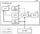
도 1을 참조하면, 에어로졸 생성 장치(1)는 배터리(11), 제어부(12) 및 히터(13)를 포함한다. 도 2 및 도 3을 참조하면, 에어로졸 생성 장치(1)는 증기화기(14)를 더 포함한다. 에어로졸 생성 장치(1)의 내부 공간에는 궐련(2)이 삽입될 수 있다. 또한, 에어로졸 생성 장치(1)는 궐련(2)이 삽입된 상태에서도 외부 공기가 유입되거나, 내부 기체가 유출 될 수 있는 구조로 제작될 수 있다.Referring to FIG. 1 , the
궐련(2)은 일반적인 연소형 궐련과 유사할 수 있다. 예를 들어, 궐련(2)은 에어로졸 생성 물질을 포함하는 제 1 부분과, 필터 등을 포함하는 제 2 부분으로 구분될 수 있다. 예를 들어, 제 1 부분은 에어로졸을 발생시키는 에어로졸 기재부와 담배 원료를 포함하는 매질부로 더 구분될 수 있다. 또는, 궐련(2)의 제 2 부분에도 에어로졸 생성 물질이 포함될 수도 있다. 예를 들어, 과립 또는 캡슐의 형태로 만들어진 에어로졸 생성 물질이 제 2 부분에 삽입될 수도 있다.The
에어로졸 생성 장치(1)의 내부에는 제 1 부분의 전체가 삽입되고, 제 2 부분은 외부에 노출될 수 있다. 또는, 에어로졸 생성 장치(1)의 내부에 제 1 부분의 일부만 삽입될 수도 있고, 제 1 부분의 전체 및 제 2 부분의 일부가 삽입될 수도 있다. 사용자는 제 2 부분을 입으로 문 상태에서 에어로졸을 흡입할 수 있다. 이때, 에어로졸은 외부 공기가 제 1 부분을 통과함으로써 생성되고, 생성된 에어로졸은 제 2 부분을 통과하여 사용자의 입으로 전달된다.The entire first part may be inserted into the
일 예로서, 외부 공기는 에어로졸 생성 장치(1)에 형성된 적어도 하나의 공기 통로를 통하여 유입될 수 있다. 예를 들어, 에어로졸 생성 장치(1)에 형성된 공기 통로의 개폐 및/또는 공기 통로의 크기는 사용자에 의하여 조절될 수 있다. 이에 따라, 무화량, 끽연감 등이 사용자에 의하여 조절될 수 있다. 다른 예로서, 외부 공기는 궐련(2)의 표면에 형성된 적어도 하나의 구멍(hole)을 통하여 궐련(2)의 내부로 유입될 수도 있다.As an example, external air may be introduced through at least one air passage formed in the
도 1 내지 도 3에 도시된 에어로졸 생성 장치(1)에는 본 개시의 실시예들과 관련된 구성요소들이 도시되어 있다. 따라서, 도 1 내지 도 3에 도시된 구성요소들 외에 다른 범용적인 구성요소들이 에어로졸 생성 장치(1)에 더 포함될 수 있음을 본 실시예들과 관련된 기술분야에서 통상의 지식을 가진 자라면 이해할 수 있다.The
도 1에는 배터리(11), 제어부(12) 및 히터(13)가 일렬로 배치된 것으로 도시되어 있다. 또한, 도 2에는 배터리(11), 제어부(12), 증기화기(14) 및 히터(13)가 일렬로 배치된 것으로 도시되어 있다. 또한, 도 3에는 증기화기(14) 및 히터(13)가 병렬로 배치된 것으로 도시되어 있다. 그러나, 에어로졸 생성 장치(1)의 내부 구조는 도 1 내지 도 3에 도시된 것에 한정되지 않는다. 다시 말해, 에어로졸 생성 장치(1)의 설계에 따라, 배터리(11), 제어부(12), 히터(13) 및 증기화기(14)의 배치는 변경될 수 있다.1 illustrates that the
궐련(2)이 에어로졸 생성 장치(1)에 삽입되면, 에어로졸 생성 장치(1)는 히터(13) 및/또는 증기화기(14)를 작동시켜, 에어로졸을 발생시킬 수 있다. 히터(13) 및/또는 증기화기(14)에 의하여 발생된 에어로졸은 궐련(2)을 통과하여 사용자에게 전달된다.When the
필요에 따라, 궐련(2)이 에어로졸 생성 장치(1)에 삽입되지 않은 경우에도 에어로졸 생성 장치(1)는 히터(13)를 가열할 수 있다. 예를 들어, 에어로졸 생성 장치(1)는 히터(13)에 부착된 물질을 제거하는 청소 동작을 수행하기 위해, 궐련(2)이 에어로졸 생성 장치(1)에 삽입되지 않은 상태에서 히터(13)를 가열할 수 있다.If desired, the aerosol-generating
히터(13)는 배터리(11)로부터 공급된 전력에 의하여 가열될 수 있다. 예를 들어, 궐련(2)이 에어로졸 생성 장치(1)에 삽입되면, 히터(13)는 궐련(2)의 외부에 위치할 수 있다. 따라서, 가열된 히터(13)는 궐련(2) 내의 에어로졸 생성 물질의 온도를 상승시킬 수 있다.The
히터(13)는 외부 전력공급원(100)으로부터 공급된 전력에 의해서도 가열될 수 있다. 예를 들어, 에어로졸 생성 장치(1)가 외부 전력공급원(100)과 전기적으로 연결된 상태에서, 히터(13)는 배터리(11)가 아닌 외부 전력공급원(100)으로부터 전력을 공급받아 가열될 수 있다. 여기서, 외부 전력공급원(100)은 에어로졸 생성 장치(1)에 전력을 공급할 수 있는 임의의 전원을 포함한다. 예를 들어, 외부 전력공급원(100)은 상용전원, 크래들 디바이스와 같이 에어로졸 생성 장치(1)를 수용하는 외장 전력공급장치, 유무선 전력전송장치 등을 포함할 수 있으나, 이에 한정되지 않는다.The
외부 전력공급원(100)은 에어로졸 생성 장치(1)와 전기적으로 연결될 수 있다. 에어로졸 생성 장치(1)에는 외부 전력공급원(100)과 전기적으로 연결되는 유/무선 인터페이싱 수단이 포함될 수 있다. 에어로졸 생성 장치(1)는 유/무선 인터페이싱 수단을 통해 외부 전력공급원(100)으로부터 전력을 공급받을 수 있다.The
예를 들어, 에어로졸 생성 장치(1)는 USB 포트, 전극 등과 같이 전기적 접속을 제공하는 단자를 포함할 수 있으며, 단자를 통해 외부 전력공급원(100)과 전기적으로 연결될 수 있다. 또한, 에어로졸 생성 장치(1)는 자기 유도 현상에 기초한 유도 결합(Inductive Coupling) 방식이나, 전자기적 공진 현상에 기초한 공진 결합(Magnetic Resonance Coupling) 방식 등의 무선전력전송 방식을 위한 전력수신수단을 포함할 수 있으며, 전력수신수단을 통해 외부 전력공급원(100)과 전기적으로 연결될 수도 있다.For example, the
다시 히터(13)에 대한 설명으로 돌아가면, 히터(13)는 전기 저항성 히터일 수 있다. 예를 들어, 히터(13)는 전기 전도성 트랙(track)을 포함하고, 전기 전도성 트랙에 전류가 흐름에 따라 히터(13)가 가열될 수 있다. 그러나, 히터(13)는 상술한 예에 한정되지 않으며, 희망 온도까지 가열될 수 있는 것이라면 제한 없이 해당될 수 있다. 여기에서, 희망 온도는 에어로졸 생성 장치(1)에 기설정되어 있을 수도 있고, 사용자에 의하여 원하는 온도로 설정될 수도 있다.Returning to the description of the
한편, 다른 예로, 히터(13)는 유도 가열식 히터일 수 있다. 구체적으로, 히터(13)에는 궐련을 유도 가열 방식으로 가열하기 위한 전기 전도성 코일을 포함할 수 있으며, 궐련은 유도 가열식 히터에 의해 가열될 수 있는 서셉터를 포함할 수 있다.Meanwhile, as another example, the
예를 들어, 히터(13)는 관 형 가열 요소, 판 형 가열 요소, 침 형 가열 요소 또는 봉 형의 가열 요소를 포함할 수 있으며, 가열 요소의 모양에 따라 궐련(2)의 내부 또는 외부를 가열할 수 있다.For example, the
또한, 에어로졸 생성 장치(1)에는 히터(13)가 복수 개 배치될 수도 있다. 이때, 복수 개의 히터(13)들은 궐련(2)의 내부에 삽입되도록 배치될 수도 있고, 궐련(2)의 외부에 배치될 수도 있다. 또한, 복수 개의 히터(13)들 중 일부는 궐련(2)의 내부에 삽입되도록 배치되고, 나머지는 궐련(2)의 외부에 배치될 수 있다. 또한, 히터(13)의 형상은 도 1 내지 도 3에 도시된 형상에 한정되지 않고, 다양한 형상으로 제작될 수 있다.In addition, a plurality of
증기화기(14)는 액상 조성물을 가열하여 에어로졸을 생성할 수 있으며, 생성된 에어로졸은 궐련(2)을 통과하여 사용자에게 전달될 수 있다. 다시 말해, 증기화기(14)에 의하여 생성된 에어로졸은 에어로졸 생성 장치(1)의 기류 통로를 따라 이동할 수 있고, 기류 통로는 증기화기(14)에 의하여 생성된 에어로졸이 궐련을 통과하여 사용자에게 전달될 수 있도록 구성될 수 있다.
예를 들어, 증기화기(14)는 액체 저장부, 액체 전달 수단 및 가열 요소를 포함할 수 있으나, 이에 한정되지 않는다. 예를 들어, 액체 저장부, 액체 전달 수단 및 가열 요소는 독립적인 모듈로서 에어로졸 생성 장치(1)에 포함될 수도 있다.For example, the
액체 저장부는 액상 조성물을 저장할 수 있다. 예를 들어, 액상 조성물은 휘발성 담배 향 성분을 포함하는 담배 함유 물질을 포함하는 액체일 수 있고, 비 담배 물질을 포함하는 액체일 수도 있다. 액체 저장부는 증기화기(14)로부터 탈/부착될 수 있도록 제작될 수도 있고, 증기화기(14)와 일체로서 제작될 수도 있다.The liquid storage unit may store the liquid composition. For example, the liquid composition may be a liquid comprising a tobacco-containing material comprising a volatile tobacco flavor component, or may be a liquid comprising a non-tobacco material. The liquid storage unit may be manufactured to be detachably/attached from the
액상 조성물은 예를 들어, 물, 솔벤트, 에탄올, 식물 추출물, 향료, 향미제, 또는 비타민 혼합물을 포함할 수 있다. 향료는 멘솔, 페퍼민트, 스피아민트 오일, 각종 과일향 성분 등을 포함할 수 있으나, 이에 제한되지 않는다. 향미제는 사용자에게 다양한 향미 또는 풍미를 제공할 수 있는 성분을 포함할 수 있다. 비타민 혼합물은 비타민 A, 비타민 B, 비타민 C 및 비타민 E 중 적어도 하나가 혼합된 것일 수 있으나, 이에 제한되지 않는다. 또한, 액상 조성물은 글리세린 및 프로필렌 글리콜과 같은 에어로졸 형성제를 포함할 수 있다.A liquid composition may include, for example, water, a solvent, ethanol, a plant extract, a flavoring, a flavoring agent, or a vitamin mixture. The fragrance may include, but is not limited to, menthol, peppermint, spearmint oil, various fruit flavoring ingredients, and the like. Flavoring agents may include ingredients that can provide a user with a variety of flavors or flavors. The vitamin mixture may be a mixture of at least one of vitamin A, vitamin B, vitamin C, and vitamin E, but is not limited thereto. Liquid compositions may also include aerosol formers such as glycerin and propylene glycol.
예를 들어, 액상 조성물은 니코틴 염이 첨가된 임의의 중량비의 글리세린 및 프로필렌 글리콜 용액을 포함할 수 있다. 액상 조성물에는 2종 이상의 니코틴 염이 포함될 수도 있다. 니코틴 염은 니코틴에 유기산 또는 무기산을 포함하는 적절한 산을 첨가함으로써 형성될 수 있다. 니코틴은 자연적으로 발생하는 니코틴 또는 합성 니코틴으로서, 액상 조성물의 총 용액 중량에 대한 임의의 적절한 중량의 농도를 가질 수 있다.For example, the liquid composition may include a solution of glycerin and propylene glycol in any weight ratio to which a nicotine salt has been added. The liquid composition may include two or more nicotine salts. Nicotine salts can be formed by adding a suitable acid, including organic or inorganic acids, to nicotine. Nicotine is either naturally occurring nicotine or synthetic nicotine, and may have any suitable weight concentration relative to the total solution weight of the liquid composition.
액체 전달 수단은 액체 저장부의 액상 조성물을 가열 요소로 전달할 수 있다. 예를 들어, 액체 전달 수단은 면 섬유, 세라믹 섬유, 유리 섬유, 다공성 세라믹과 같은 심지(wick)가 될 수 있으나, 이에 한정되지 않는다.The liquid delivery means may deliver the liquid composition of the liquid reservoir to the heating element. For example, the liquid delivery means may be, but is not limited to, a wick such as cotton fiber, ceramic fiber, glass fiber, or porous ceramic.
증기화기(14)의 가열 요소는 액체 전달 수단에 의해 전달되는 액상 조성물을 가열하기 위한 요소이다. 예를 들어, 증기화기(14)의 가열 요소는 금속 열선, 금속 열판, 세라믹 히터 등이 될 수 있으나 이에 한정되지 않고, 가열 요소는 니크롬선과 같은 전도성 필라멘트로 구성될 수 있고, 액체 전달 수단에 감기는 구조로 배치될 수 있다. 가열 요소는, 전류 공급에 의해 가열될 수 있으며, 가열 요소와 접촉된 액체 조성물에 열을 전달하여, 액체 조성물을 가열할 수 있다. 그 결과, 에어로졸이 생성될 수 있다.The heating element of the
한편, 증기화기(14)는 카토마이저(cartomizer) 또는 무화기(atomizer) 등 다양한 용어들로 지칭될 수 있다.Meanwhile, the
배터리(11)는 에어로졸 생성 장치(1)가 동작하는데 필요한 전력을 저장한다. 배터리(11)는 히터(13) 및/또는 증기화기(14)가 가열될 수 있도록 전력을 공급할 수 있고, 제어부(12)가 동작하는데 필요한 전력을 공급할 수 있다. 또한, 배터리(11)는 에어로졸 생성 장치(1)에 설치된 디스플레이, 센서, 모터 등이 동작하는데 필요한 전력을 공급할 수 있다.The
배터리(11)는 충전이 가능한 배터리이다. 예를 들어, 배터리(11)는 리튬폴리머(LiPoly) 배터리일 수 있으나, 이에 제한되지 않는다. 배터리(11)는 외부 전력공급원(100)으로부터 공급된 전력에 의해 충전될 수 있다.The
도 1 내지 도 3에는 도시되지 않았으나, 에어로졸 생성 장치(1)는 별도의 크래들 디바이스와 같은 외장 전력공급장치(도 7의 3)와 함께 시스템을 구성할 수도 있다. 예를 들어, 외장 전력공급장치는 에어로졸 생성 장치(1)의 배터리(11)의 충전에 이용될 수 있다. 또한, 외장 전력공급장치와 에어로졸 생성 장치(1)가 결합된 상태에서 히터(13) 및/또는 증기화기(14)가 가열될 수도 있다.Although not shown in FIGS. 1 to 3 , the
제어부(12)는 에어로졸 생성 장치(1)의 동작을 전반적으로 제어한다. 구체적으로, 제어부(12)는 배터리(11), 히터(13) 및 증기화기(14)뿐만 아니라 에어로졸 생성 장치(1)에 포함된 다른 구성들의 동작을 제어한다. 또한, 제어부(12)는 에어로졸 생성 장치(1)의 구성들 각각의 상태를 확인하여, 에어로졸 생성 장치(1)가 동작 가능한 상태인지 여부를 판단할 수도 있다.The
제어부(12)는 적어도 하나의 프로세서를 포함한다. 프로세서는 다수의 논리 게이트들의 어레이로 구현될 수도 있고, 범용적인 마이크로 프로세서와 이 마이크로 프로세서에서 실행될 수 있는 프로그램이 저장된 메모리의 조합으로 구현될 수도 있다. 또한, 다른 형태의 하드웨어로 구현될 수도 있음을 본 실시예가 속하는 기술분야에서 통상의 지식을 가진 자라면 이해할 수 있다.The
제어부(12)는 에어로졸 생성 장치(1)에 포함된 적어도 하나의 센서를 이용하여 센싱 데이터를 획득하고, 획득된 센싱 데이터에 따라 히터(13) 및 증기화기(14)의 동작 제어, 배터리(11)의 충전, 흡연의 제한, 궐련(또는 카트리지) 삽입 유/무 판단, 알림 표시 등과 같은 다양한 기능들이 수행되도록 에어로졸 생성 장치(1)를 제어할 수 있다.The
제어부(12)는 히터(13) 및/또는 증기화기(14)로의 전력 공급을 제어한다. 제어부(12)는 에어로졸 생성 장치(1)에 포함된 적어도 하나의 센서에 의해 센싱된 결과에 따라 히터(13) 및/또는 증기화기(14)로의 전력 공급을 개시 또는 중단시킬 수 있다. 제어부(12)는 히터(13) 및/또는 증기화기(14)가 소정의 온도까지 가열되거나 적절한 온도를 유지할 수 있도록, 히터(13) 및/또는 증기화기(14)에 공급되는 전력의 양 및 전력이 공급되는 시간을 제어할 수 있다. 제어부(12)는 에어로졸 생성 장치(1)가 외부 전력공급원(100)과 연결된 상태에서도 히터(13) 및/또는 증기화기(14)에 전력을 공급할 수 있다.The
제어부(12)는 외부 전력공급원(100)과 에어로졸 생성 장치(1)가 전기적으로 연결된 상태인지 여부를 감지할 수 있다. 외부 전력공급원(100)과 에어로졸 생성 장치(1)가 전기적으로 연결된 상태임이 감지되면, 제어부(12)는 히터(13) 및/또는 증기화기(14)의 가열상태를 모니터링하고, 모니터링된 가열상태에 기초하여 히터(13) 및/또는 증기화기(14)의 가열과 배터리(11)의 충전을 위한 외부 전력공급원(100)으로부터의 전력 공급을 제어할 수 있다.The
이하에서는 에어로졸 생성 장치(1)가 외부 전력공급원(100)과 전기적으로 연결된 경우 가열 및 충전을 제어하는 방법에 대하여 구체적으로 설명한다. 가열을 제어하는 방법과 관련하여, 편의상 히터(13)의 가열을 제어하는 방법을 중심으로 설명하지만 증기화기(14)의 가열을 제어하는 방법에도 이하의 설명이 유사하게 적용될 수 있다.Hereinafter, a method for controlling heating and charging when the
도 4 및 도 5는 히터의 가열상태에 따라 히터의 가열 및 배터리의 충전이 제어되는 방법을 설명하기 위한 도면들이다.4 and 5 are diagrams for explaining a method of controlling heating of a heater and charging of a battery according to a heating state of the heater.
도 4는 히터(13)의 가열이 수행되는 동안 기설정된 온도 프로파일에 따른 히터(13)의 온도 변화의 예시를 나타낸다. 제어부(12)는 기설정된 온도 프로파일에 기초하여 히터(13)에 공급되는 전력을 제어한다. 예를 들어, 기설정된 온도 프로파일은 예열구간(410)의 온도 프로파일 및 유지구간(420)의 온도 프로파일을 포함할 수 있다. 제어부(12)는 예열구간(410)의 온도 프로파일에 기초하여, 히터(13)의 온도가 목표온도까지 가열되도록 히터(13)에 공급되는 전력을 제어할 수 있다. 또한, 제어부(12)는 유지구간(420)의 온도 프로파일에 기초하여, 히터(13)의 온도가 기설정된 온도(또는 온도 범위)에서 유지되도록 히터(13)에 공급되는 전력을 제어할 수 있다.4 shows an example of a temperature change of the
예열구간(410) 및 유지구간(420)에서의 온도 프로파일에 따른 히터(13)의 온도 변화는 도 4에 도시된 바로 한정되지 않는다. 예를 들어, 예열구간(410) 및 유지구간(420)은 각각 복수의 구간들로 더 구분될 수 있고, 예열구간(410)의 각각의 구간에 대응하는 목표온도까지 히터(13)의 온도가 증가하거나, 유지구간(420)의 각각의 구간에 대응하는 기설정된 온도(또는 온도 범위)에서 히터(13)의 온도가 유지될 수 있다.The temperature change of the
한편, 예열구간(410)에서는 가능한 한 빠르게 히터(13)의 온도가 목표온도에 도달하도록 비교적 짧은 시간 동안 높은 레벨의 전력이 히터(13)에 공급되고, 유지구간(420)에서는 히터(13)의 온도가 유지되도록 예열구간(410)에서 공급되는 것보다 낮은 레벨의 전력이 히터(13)에 공급된다.Meanwhile, in the preheating section 410 , a high level of power is supplied to the
에어로졸 생성 장치(1)가 외부 전력공급원(100)과 전기적으로 연결된 경우, 예열구간(410)과 같이 비교적 짧은 시간 동안 높은 레벨의 전력이 히터(13)에 공급되는 구간에서 히터(13)의 가열과 함께 배터리(11)의 충전이 수행되면, 배터리(11)의 충전이 효율적으로 수행되지 않을 수 있다. 또한, 이러한 경우 배터리(11)로부터 높은 레벨의 전력이 출력됨과 동시에 배터리(11)에 대한 충전이 이루어지게 됨으로써 배터리(11)의 충전/방전회로의 동작 오류가 발생하게 될 수 있다. 이에 따라, 히터(13)의 가열 및 배터리(11)의 충전이 안정적으로 수행되지 않을 수 있다.When the
따라서, 에어로졸 생성 장치(1)와 외부 전력공급원(100)이 전기적으로 연결된 상태에서 히터(13)의 가열이 수행되는 경우, 히터(13)의 가열상태를 고려하여 히터(13)의 가열 및 배터리(11)의 충전을 제어할 필요가 있다.Therefore, when the heating of the
본 개시의 일 실시예에 따른 제어부(12)는 에어로졸 생성 장치(1)가 외부 전력공급원(100)과 전기적으로 연결된 경우 히터(13)의 가열상태를 모니터링한다. 제어부(12)는 히터(13)의 가열 개시 시점으로부터 경과한 시간, 히터(13)의 온도, 히터(13)에 공급되는 전력 레벨, 히터(13)에 공급되는 전류 레벨 등을 포함하는, 히터(13)의 가열과 관련된 적어도 하나의 데이터를 기초로 히터(13)의 가열상태를 모니터링할 수 있다.The
제어부(12)는 모니터링된 히터(13)의 가열상태가 급속가열상태인 것으로 판단된 경우, 외부 전력공급원(100)에 의한 배터리(11)의 충전 없이 히터(13)의 가열을 수행하도록, 히터(13)로의 전력 공급 및 배터리(11)로의 전력 공급을 제어할 수 있다. 또한, 제어부(12)는 모니터링된 히터(13)의 가열상태가 급속가열상태가 아닌 것으로 판단된 경우, 외부 전력공급원(100)에 의한 배터리(11)의 충전과 히터(13)의 가열을 함께 수행하도록, 히터(13)로의 전력 공급 및 배터리(11)로의 전력 공급을 제어할 수 있다.When it is determined that the monitored heating state of the
여기서, 급속가열상태는 비교적 짧은 시간 동안 히터(13)의 온도를 상승시키기 위해 높은 전력 레벨이 요구되는 가열상태를 의미한다. 예를 들어, 급속가열상태는 히터(13)의 온도가 목표온도까지 증가하는 예열구간에서의 가열상태, 히터(13)가 기준전력 이상의 전력을 공급받는 경우의 가열상태, 히터(13)가 기준전류 이상의 전류를 공급받는 경우의 가열상태 및 히터(13)의 온도 변화량이 기준변화량 이상인 경우의 가열상태를 포함할 수 있다.Here, the rapid heating state means a heating state in which a high power level is required to increase the temperature of the
도 5는 히터(13)의 가열이 수행되는 동안 기설정된 온도 프로파일에 따른 히터(13)의 온도 변화의 다른 예시를 나타낸다.5 shows another example of a temperature change of the
일 실시예에서, 제어부(12)는 히터(13)의 가열이 수행되는 구간이 예열구간(510)에 해당하는 것을 확인하면 히터(13)의 가열상태가 급속가열상태인 것으로 판단하고, 히터(13)의 가열이 수행되는 구간이 유지구간(520)에 해당하는 것을 확인하면 히터(13)의 가열상태가 급속가열상태가 아닌 것으로 판단할 수 있다. 예를 들어, 제어부(12)는 히터(13)의 온도가 목표온도에 도달한 이후 소정의 시간이 경과되었는지 여부를 기초로 예열구간(510)에 해당하는지 여부를 확인할 수 있다. 다른 예로, 제어부(12)는 히터(13)에 공급되는 전류가 소정의 전류(예: I1) 이상인지 여부 또는 히터(13)에 공급되는 전력이 소정의 전력 이상인지 여부를 기초로 예열구간(510)에 해당하는지 여부를 확인할 수 있다.In one embodiment, the
한편, 예열구간(510)이 완료된 이후 유지구간(520)에서도 히터(13)의 온도를 상승시키기 위해 순간적으로 높은 레벨의 전력이 히터(13)에 공급되는 구간이 존재할 수 있다. 예컨대, 사용자의 퍼프에 의해 히터(13)의 온도 감소가 발생하는 구간(530)이 이에 해당될 수 있다. 이 경우, 구간(540)과 같이, 감소된 히터(13)의 온도를 적절한 온도로 상승시키기 위해 히터(13)에 순간적으로 높은 레벨의 전류가 공급될 수 있다.Meanwhile, even after the preheating section 510 is completed, even in the maintenance section 520 , there may be a section in which a high level of power is instantaneously supplied to the
이에 따라, 예열구간(510) 및 유지구간(520)을 포함하는 전체 가열구간에 대하여 히터(13)의 가열과 배터리(11)의 충전이 효율적이고 안정적으로 수행되도록, 제어부(12)는 전체 가열구간에 걸쳐, 히터(13)의 가열상태가 급속가열상태인지 여부를 기초로 히터(13) 및 배터리(11)로의 전력 공급을 제어할 수 있다.Accordingly, the
일 실시예에서, 제어부(12)는 기준전력 이상의 전력이 히터(13)에 공급되는 것에 의해 히터(13)의 가열이 수행되고 있는 것을 확인하면, 히터(13)의 가열상태가 급속가열상태인 것으로 판단할 수 있다. 여기서, 기준전력은 미리 설정되는 전력값으로서, 하나의 특정 전력값이거나 히터(13)의 가열구간에 따라 다르게 설정되는 복수의 전력값들을 포함할 수 있다. 예를 들어, 예열구간(510)에 대응하는 기준전력은 유지구간(520)에 대응하는 기준전력보다 높게 설정될 수 있다.In one embodiment, when the
일 실시예에서, 제어부(12)는 기준전류 이상의 전류가 히터(13)에 공급되는 것에 의해 히터(13)의 가열이 수행되고 있는 것을 확인하면, 히터(13)의 가열상태가 급속가열상태인 것으로 판단할 수 있다. 여기서, 기준전류는 미리 설정되는 전류값으로서, 하나의 특정 전류값이거나 히터(13)의 가열구간에 따라 다르게 설정되는 복수의 전류값들을 포함할 수 있다.In one embodiment, when the
예를 들어, 예열구간(510)에 대응하는 기준전류는 I1로 설정되고, 유지구간(520)에 대응하는 기준전류는 I2 또는 I3으로 설정될 수 있다. 기준전류가 I2인 경우, 구간(540)에서 히터(13)의 가열상태는 급속가열상태가 아닌 것으로 판단되고, 구간(540) 전체에서 배터리(11)의 충전과 히터(13)의 가열이 함께 수행될 수 있다. 기준전류가 I3인 경우, 구간(540) 중 I3보다 낮은 전류가 히터(13)에 공급되는 구간에서 히터(13)의 가열상태는 급속가열상태가 아닌 것으로 판단되고, 해당 구간에서만 배터리(11)의 충전과 히터(13)의 가열이 함께 수행될 수 있다.For example, the reference current corresponding to the preheating period 510 maybe set to I 1 , and the reference current corresponding to the sustain period 520 may be set toI 2 or I3 . When the reference current is I2 , it is determined that the heating state of the
일 실시예에서, 제어부(12)는 히터(13)의 온도 변화량이 기준변화량 이상인 것을 확인하면, 히터(13)의 가열상태가 급속가열상태인 것으로 판단할 수 있다. 여기서, 기준변화량은 미리 설정되는 온도 변화량으로서, 하나의 특정값이거나 히터(13)의 가열구간에 따라 다르게 설정되는 복수의 값들을 포함할 수 있다.In one embodiment, when the
예를 들어, 히터(13)의 온도가 T1에서 T2로 증가한 경우, 온도 변화량(T2-T1)이 기준변화량 이상이면 히터(13)의 가열상태가 급속가열상태인 것으로 판단될 수 있다. 한편, 히터(13)의 온도의 급속한 상승이 예상되는 가열상태도 급속가열상태에 포함될 수 있다. 예를 들어, 히터(13)의 온도가 T2에서 T1로 감소한 경우, 온도 변화량(|T2-T1|)이 기준변화량 이상이면 히터(13)의 가열상태가 급속가열상태인 것으로 판단될 수 있다. 히터(13)의 온도가 기준변화량 이상으로 감소하면, 온도 프로파일에 따라 히터(13)의 온도가 적정한 온도까지 급속히 상승될 것이 예상될 수 있기 때문이다.For example, when the temperature of the
이하에서는 도 6 내지 도 10을 참조하여 에어로졸 생성 장치 내 히터 및 배터리가 전력을 공급받는 경로에 대하여 설명한다.Hereinafter, a path through which the heater and the battery in the aerosol generating device are supplied with power will be described with reference to FIGS. 6 to 10 .
에어로졸 생성 장치는 분리형 타입 또는 일체형 타입으로 구현될 수 있다. 분리형 타입의 에어로졸 생성 장치는, 에어로졸 생성 장치를 수용하는 내부 공간이 포함된 외장 전력공급장치(예: 크래들 디바이스)와 함께 시스템을 구성하며, 외장 전력공급장치로부터 탈부착 가능한 구조로 구현될 수 있다. 한편, 일체형 타입의 에어로졸 생성 장치는 상기 외장 전력공급장치와 시스템을 구성하지 않도록 구현될 수 있다.The aerosol generating device may be implemented as a separate type or an integral type. The detachable type aerosol generating device constitutes a system together with an external power supply (eg, a cradle device) including an internal space for accommodating the aerosol generating device, and may be implemented in a structure detachable from the external power supply. On the other hand, the integrated type aerosol generating device may be implemented so as not to configure the system with the external power supply.
예를 들어, 도 1 내지 도 3에서 설명한 에어로졸 생성 장치(1)가 분리형 타입인 경우 외부 전력공급원(100)은 상기 외장 전력공급장치일 수 있으며, 에어로졸 생성 장치(1)가 일체형 타입인 경우 외부 전력공급원(100)은 상기 외장 전력공급장치를 제외한 임의의 외부 전원(도 6의 60)일 수 있다.For example, when the
이러한 에어로졸 생성 장치의 타입에 따라 히터로의 전력 공급과 배터리로의 전력 공급이 일부 다르게 제어될 수 있다. 우선, 도 6을 참조하여 일체형 타입의 에어로졸 생성 장치의 제어 방법에 대하여 설명한다.Power supply to the heater and power supply to the battery may be controlled differently depending on the type of the aerosol generating device. First, a control method of an integrated type aerosol generating device will be described with reference to FIG. 6 .
도 6은 일 실시예에 따른 일체형 타입의 에어로졸 생성 장치 내 히터 및 배터리가 전력을 공급받는 경로를 설명하기 위한 도면이다.6 is a view for explaining a path through which the heater and the battery in the integrated type aerosol generating device according to an embodiment are supplied with power.
에어로졸 생성 장치(600)는 히터(610), 배터리(620), 제어부(630), 제 1 스위칭부(640), 제 2 스위칭부(650) 및 충전 IC(Charger Integrated Circuit, 660)를 포함할 수 있다.The
제 1 스위칭부(640)는 배터리(620)로부터 히터(610)로 전력이 공급되는 전력 공급 경로 상에 배치되며, 제 2 스위칭부(650)는 외부 전원(60)으로부터 히터(610)로 전력이 공급되는 전력 공급 경로 상에 배치된다.The
충전 IC(660)는 외부 전원(60)으로부터 공급되는 전력을 배터리(620) 및 히터(610)에 공급한다. 예를 들어, 충전 IC(660)는 외부 전원(60)으로부터 공급되는 전력을 배터리(620)의 충전에 적절한 전력 및 히터(610)의 가열에 적절한 전력으로 변환할 수 있다.The
에어로졸 생성 장치(600)가 외부 전원(60)과 전기적으로 연결되지 않은 경우, 제어부(630)는 경로 A에 따라 배터리(620)로부터 히터(610)로 전력이 공급되도록 제 1 스위칭부(640) 및 충전 IC(660)를 제어할 수 있다.When the
에어로졸 생성 장치(600)가 외부 전원(60)과 전기적으로 연결된 경우, 제어부(630)는 경로 A에 따른 배터리(620)로부터 히터(610)로의 전력 공급을 차단하도록 제 1 스위칭부(640)를 제어할 수 있다. 또한, 제어부(630)는 경로 B에 따라 공급되는 전력에 의해 히터(610)의 가열 및 배터리(620)의 충전을 수행하도록, 히터(610) 및 배터리(620)로의 전력 공급을 제어할 수 있다.When the
구체적으로, 모니터링된 히터(610)의 가열상태가 급속가열상태인 것으로 판단된 경우, 제어부(630)는 외부 전원(60)으로부터 배터리(620)로 전력이 공급되지 않도록 충전 IC(660)를 제어하고, 외부 전원(60)으로부터 히터(610)로 전력이 공급되도록 제 2 스위칭부(650)를 제어할 수 있다. 반면, 모니터링된 히터(610)의 가열상태가 급속가열상태가 아닌 것으로 판단된 경우, 제어부(630)는 외부 전원(60)으로부터 히터(610)로의 전력 공급과 함께 외부 전원(60)으로부터 배터리(620)로 전력이 공급되도록 충전 IC(660)를 제어할 수 있다.Specifically, when it is determined that the heating state of the monitored
이하, 도 7 내지 10을 참조하여, 분리형 타입의 에어로졸 생성 장치의 제어 방법에 대하여 설명한다.Hereinafter, with reference to FIGS. 7 to 10, a control method of a detachable type aerosol generating device will be described.
도 7 및 도 8은 분리형 타입의 에어로졸 생성 장치가 외장 전력공급장치에 수용된 예들을 도시한 도면들이다.7 and 8 are diagrams illustrating examples in which a detachable type aerosol generating device is accommodated in an external power supply.
도 7 내지 도 8에 도시된 에어로졸 생성 장치(1) 및 외장 전력공급장치(3)에는 각 장치에 대해서 상술한 설명이 모순되지 않는 범위에서 유사하게 적용될 수 있다. 따라서, 이하에서는 상술한 설명과 중복되지 않는 내용에 대해서 주로 설명한다.The
에어로졸 생성 장치(1)는 외장 전력공급장치(3)에 탈부착 가능하도록 수용될 수 있다. 사용자는 에어로졸 생성 장치(1)의 내부 공간에 궐련(2)을 삽입한 상태에서, 에어로졸 생성 장치(1)만을 이용하여 흡연을 실시하거나, 또는 도 7에 도시된 바와 같이 에어로졸 생성 장치(1)가 외장 전력공급장치(3)와 결합된 상태에서 흡연을 실시할 수 있다. 또한, 사용자는 도 8에 도시된 바와 같이 에어로졸 생성 장치(1)를 일정 각도로 틸트시켜 흡연을 실시할 수도 있다.The
외장 전력공급장치(3)는 제어부(32) 및 배터리(33)를 포함한다. 또한, 외장 전력공급장치(3)는 에어로졸 생성 장치(1)가 수용될 수 있는 내부 공간(31)을 포함한다. 예를 들어, 내부 공간(31)은 일 측면에 형성될 수 있다. 따라서, 외장 전력공급장치(3)가 별도의 캡을 포함하지 않더라도 에어로졸 생성 장치(1)는 외장 전력공급장치(3)에 삽입 고정될 수 있다.The external
제어부(32)는 외장 전력공급장치(3)의 동작을 전반적으로 제어한다. 제어부(32)는 외장 전력공급장치(3)와 에어로졸 생성 장치(1)가 결합된 상태인지 판단할 수 있으며, 판단된 결합 상태에 따라 외장 전력공급장치(3)의 동작을 제어할 수 있다. 예를 들어, 에어로졸 생성 장치(1)와 외장 전력공급장치(3)가 결합되면, 제어부(32)는 배터리(33)의 전력을 에어로졸 생성 장치(1)에 공급함으로써, 에어로졸 생성 장치(1)의 배터리를 충전하거나 히터를 가열시킬 수 있다.The
제어부(32)는 적어도 하나의 프로세서를 포함한다. 프로세서는 다수의 논리 게이트들의 어레이로 구현될 수도 있고, 범용적인 마이크로 프로세서와 이 마이크로 프로세서에서 실행될 수 있는 프로그램이 저장된 메모리의 조합으로 구현될 수도 있다. 또한, 다른 형태의 하드웨어로 구현될 수도 있음을 본 실시예가 속하는 기술분야에서 통상의 지식을 가진 자라면 이해할 수 있다.The
배터리(33)는 외장 전력공급장치(3)가 동작하는데 이용되는 전력을 공급한다. 또한 배터리(33)는 에어로졸 생성 장치(1)의 동작 및 충전에 이용되는 전력을 공급한다.The
외장 전력공급장치(3) 및 에어로졸 생성 장치(1)는 유선통신(예:USB) 또는 무선통신(예: WI-FI, WI-FI Direct, Bluetooth, NFC(Near-Field Communication) 등)을 수행하기 위한 통신 인터페이싱 모듈을 포함할 수 있으며, 통신 인터페이싱 모듈을 통해 서로 통신할 수 있다.The external
도 9 및 도 10은 일 실시예에 따른 분리형 타입의 에어로졸 생성 장치 내 히터 및 배터리가 전력을 공급받는 경로를 설명하기 위한 도면들이다. 도 9는 외장 전력공급장치가 외부 전원과 연결되지 않은 경우를 예시하며, 도 10은 외장 전력공급장치가 외부 전원과 연결된 경우를 예시한다.9 and 10 are diagrams for explaining a path through which a heater and a battery in a detachable type aerosol generating device are supplied with power according to an embodiment. 9 illustrates a case in which the external power supply is not connected to an external power source, and FIG. 10 illustrates a case in which the external power supply is connected to an external power source.
도 9를 참조하면, 에어로졸 생성 장치(910)는 히터(911), 배터리(913) 및 제어부(915)를 포함한다. 외장 전력공급장치(920)는 배터리(921), 제어부(923), 제 1 스위칭부(925), 제 2 스위칭부(927) 및 충전 IC(929)를 포함할 수 있다.Referring to FIG. 9 , the
제 1 스위칭부(925)는 배터리(921)로부터 히터(911)로 전력이 공급되는 전력 공급 경로 상에 배치되며, 제 2 스위칭부(927)는 배터리(921)로부터 배터리(913)로 전력이 공급되는 전력 공급 경로 상에 배치된다.The
충전 IC(929)는 배터리(921)로부터 공급되는 전력을 배터리(913) 및 히터(911)에 공급한다. 예를 들어, 충전 IC(929)는 배터리(921)으로부터 공급되는 전력을 배터리(913)의 충전에 적절한 전력 및 히터(911)의 가열에 적절한 전력으로 변환할 수 있다.The
에어로졸 생성 장치(910)가 외장 전력공급장치(920)와 전기적으로 연결된 경우, 에어로졸 생성 장치(910)의 제어부(915)는 배터리(913)로부터 히터(911)로의 전력 공급을 차단할 수 있다. 또한, 제어부(915)는 경로 C에 따라 공급되는 전력에 의해 히터(911)의 가열 및 배터리(913)의 충전을 수행하도록, 히터(911) 및 배터리(913)로의 전력 공급을 제어할 수 있다.When the
일 실시예에서, 제어부(915)는 외장 전력공급장치(920)에 포함된 제 1 스위칭부(925) 및 제 2 스위칭부(927)의 동작에 의해, 외장 전력공급장치(920)의 배터리(921)로부터 히터(911) 및 배터리(913)로의 전력 공급이 제어되도록, 모니터링된 히터(911)의 가열상태와 관련된 정보를 외장 전력공급장치(920)에 전달할 수 있다.In one embodiment, the
예를 들어, 히터(911)의 가열상태와 관련된 정보는 히터(911)의 가열 개시 시점으로부터 경과한 시간, 히터(911)의 온도, 히터(911)에 공급되는 전력 레벨, 히터(911)에 공급되는 전류 레벨 중 적어도 하나를 포함할 수 있으나, 이에 한정되지 않는다.For example, information related to the heating state of the
제어부(923)는 경로 C에 따라 공급되는 전력에 의해 히터(911)의 가열 및 배터리(913)의 충전이 수행되도록, 에어로졸 생성 장치(910)로부터 전달받은 정보를 이용하여 제 1 스위칭부(925), 제 2 스위칭부(927) 및 충전 IC(929)를 제어할 수 있다.The
구체적으로, 히터(911)의 가열상태와 관련된 정보가 급속가열상태를 나타내는 경우, 제어부(923)는 외장 전력공급장치(920)의 배터리(921)로부터 에어로졸 생성 장치(910)의 배터리(913)로 전력이 공급되지 않도록 제 2 스위칭부(927) 및 충전 IC(929)를 제어하고, 배터리(921)로부터 히터(911)로 전력이 공급되도록 제 1 스위칭부(925)를 제어할 수 있다. 반면, 히터(911)의 가열상태와 관련된 정보가 급속가열상태를 나타내지 않는 경우, 제어부(923)는 배터리(921)로부터 히터(911)로의 전력 공급과 함께 배터리(921)로부터 배터리(913)로 전력이 공급되도록 제 2 스위칭부(927)를 제어할 수 있다.Specifically, when the information related to the heating state of the
다른 실시예에 따르면, 외장 전력공급장치(920)의 제어부(923)가 직접 히터(911)의 가열상태를 모니터링하고, 모니터링된 히터(911)의 가열상태가 급속가열상태인지 여부에 대해 판단하여 배터리(921)로부터 히터(911) 및 배터리(913)로의 전력 공급을 제어할 수도 있다.According to another embodiment, the
도 10을 참조하면, 외장 전력공급장치(920)는 외부 전원(100)과 전기적으로 연결될 수 있다. 이 경우, 에어로졸 생성 장치(910)의 히터(911) 및 배터리(913)로의 전력 공급은 경로 C 및 경로 D 중 어느 하나의 경로를 따를 수 있다. 경로 C는 외장 전력공급장치(920)의 배터리(921)로부터의 전력 공급 경로를 나타내며, 경로 D는 외장 전력공급장치(920)와 연결된 외부 전원(100)으로부터의 전력 공급 경로를 나타낸다. 예를 들어, 외부 전원(100)이 연결된 경우, 경로 C에 따른 전력 공급 경로는 경로 D에 따른 전력 공급 경로로 변경되거나, 경로 C 및 경로 C 중 어느 하나의 경로에 따른 전력 공급 경로가 선택적으로 형성될 수 있다.Referring to FIG. 10 , the
경로 D에 있어서, 히터(911)의 가열상태와 관련된 정보가 급속가열상태를 나타내는 경우, 제어부(923)는 외부 전원(100)으로부터 에어로졸 생성 장치(910)의 배터리(913)로 전력이 공급되지 않도록 제 2 스위칭부(927)를 제어하고, 외부 전원(100)으로부터 히터(911)로 전력이 공급되도록 충전 IC(929) 및 제 1 스위칭부(925)를 제어할 수 있다. 반면, 히터(911)의 가열상태와 관련된 정보가 급속가열상태를 나타내지 않는 경우, 제어부(923)는 외부 전원(100)으로부터 히터(911)로의 전력 공급과 함께 외부 전원(100)으로부터 배터리(913)로 전력이 공급되도록 제 2 스위칭부(927)를 제어할 수 있다.In the path D, when the information related to the heating state of the
이하, 도 11 및 도 12를 참조하여, 일부 실시예에 따른 에어로졸 생성 장치의 동작 방법에 대하여 설명한다.Hereinafter, an operating method of an aerosol generating device according to some embodiments will be described with reference to FIGS. 11 and 12 .
도 11은 일 실시예에 따른 에어로졸 생성 장치의 동작 방법을 나타내는 흐름도이다.11 is a flowchart illustrating a method of operating an aerosol generating device according to an embodiment.
단계 S1110에서, 에어로졸 생성 장치가 외부 전력공급원과 전기적으로 연결된 경우, 에어로졸 생성 장치는 히터의 가열상태를 모니터링한다. 에어로졸 생성 장치는 히터의 가열 개시 시점으로부터 경과한 시간, 히터의 온도, 히터에 공급되는 전력 레벨, 히터에 공급되는 전류 레벨 등을 포함하는, 히터의 가열과 관련된 적어도 하나의 데이터를 기초로 히터의 가열상태를 모니터링할 수 있다.In step S1110, when the aerosol generating device is electrically connected to an external power supply source, the aerosol generating device monitors the heating state of the heater. The aerosol generating device is configured to control the heater based on at least one data related to heating of the heater, including a time elapsed from the start of heating of the heater, a temperature of the heater, a power level supplied to the heater, a current level supplied to the heater, and the like. The heating status can be monitored.
단계 S1120에서, 에어로졸 생성 장치는 모니터링된 히터의 가열상태가 급속가열상태인 것으로 판단된 경우 외부 전력공급원에 의한 배터리의 충전 없이 히터의 가열을 수행을 수행한다. 단계 S1120은 에어로졸 생성 장치가 외부 전력공급원으로부터 배터리로의 전력 공급이 차단되도록 배터리로의 전력 공급을 제어하는 단계를 포함할 수 있다.In step S1120, when it is determined that the monitored heating state of the heater is a rapid heating state, the aerosol generating device performs heating of the heater without charging the battery by an external power supply source. Step S1120 may include controlling the power supply to the battery so that the aerosol generating device cuts off the power supply to the battery from the external power supply.
여기서, 급속가열상태는 비교적 짧은 시간 동안 히터의 온도를 상승시키기 위해 높은 전력 레벨이 요구되는 가열상태를 의미한다. 예를 들어, 급속가열상태는 히터의 온도가 목표온도까지 증가하는 예열구간에서의 가열상태, 히터가 기준전력 이상의 전력을 공급받는 경우의 가열상태, 히터가 기준전류 이상의 전류를 공급받는 경우의 가열상태 및 히터의 온도 변화량이 기준변화량 이상인 경우의 가열상태를 포함할 수 있다.Here, the rapid heating state means a heating state in which a high power level is required to increase the temperature of the heater for a relatively short time. For example, the rapid heating state is a heating state in the preheating section in which the temperature of the heater increases to a target temperature, a heating state when the heater is supplied with power greater than or equal to the reference power, and heating when the heater is supplied with a current greater than the reference current. The state and the heating state when the temperature change amount of the heater is greater than the reference change amount may be included.
단계 S1130에서, 에어로졸 생성 장치는 모니터링된 히터의 가열상태가 급속가열상태가 아닌 것으로 판단된 경우 외부 전력공급원에 의한 배터리의 충전과 히터의 가열을 함께 수행한다. 단계 S1130은 에어로졸 생성 장치가 외부 전력공급원으로부터 히터로의 전력 공급과 함께 외부 전력공급원으로부터 배터리로 전력이 공급되도록 배터리로의 전력 공급을 제어하는 단계를 포함할 수 있다.In step S1130, when it is determined that the monitored heating state of the heater is not a rapid heating state, the aerosol generating device performs charging of the battery by an external power supply and heating of the heater together. Step S1130 may include controlling the power supply to the battery so that the aerosol generating device supplies power to the battery from the external power source together with the power supply to the heater from the external power source.
도 12는 다른 일 실시예에 따른 에어로졸 생성 장치의 동작 방법을 나타내는 흐름도이다.12 is a flowchart illustrating a method of operating an aerosol generating device according to another embodiment.
단계 S1210에서, 에어로졸 생성 장치가 외부 전력공급원과 전기적으로 연결된다. 에어로졸 생성 장치는 외부 전력공급원과 전기적으로 연결된 상태인지 여부를 감지할 수 있다. 에어로졸 생성 장치가 외부 전력공급원과의 전기적 연결을 감지하면, 단계 S1220에서, 에어로졸 생성 장치는 외부 전력공급원으로부터 공급된 전력에 의해 배터리의 충전을 수행할 수 있다.In step S1210, the aerosol generating device is electrically connected to an external power supply. The aerosol generating device may detect whether it is electrically connected to an external power supply. When the aerosol generating device detects an electrical connection with an external power source, in step S1220, the aerosol generating device may perform charging of the battery by power supplied from the external power source.
단계 S1230에서, 에어로졸 생성 장치는 히터의 가열 개시를 요구하는 신호의 발생여부를 감지할 수 있다. 예를 들어, 히터의 가열 개시를 요구하는 신호는 에어로졸 생성 장치에 포함된 입력수단을 통하여 사용자에 의해 입력된 신호, 궐련 또는 카트리지의 삽입(체결)을 나타내는 신호 등이 될 수 있으나, 이에 한정되지 않는다.In step S1230, the aerosol generating device may detect whether a signal for requesting the start of heating of the heater is generated. For example, the signal for requesting the start of heating of the heater may be a signal input by a user through an input means included in the aerosol generating device, a signal indicating insertion (fastening) of a cigarette or cartridge, etc., but is not limited thereto. does not
히터의 가열 개시를 요구하는 신호의 발생이 감지되지 않은 경우, 에어로졸 생성 장치는 계속하여 배터리를 충전시킬 수 있다. 반면, 히터의 가열 개시를 요구하는 신호의 발생이 감지된 경우, 에어로졸 생성 장치는 히터의 가열을 수행하고, 배터리의 충전을 중단할 수 있다(S1240).If generation of a signal requesting initiation of heating of the heater is not detected, the aerosol generating device may continue to charge the battery. On the other hand, when generation of a signal requesting the start of heating of the heater is sensed, the aerosol generating device may heat the heater and stop charging the battery (S1240).
단계 S1250에서, 에어로졸 생성 장치는 히터의 가열상태를 모니터링하고, 모니터링된 히터의 가열상태가 급속가열상태인지 여부를 판단할 수 있다. 모니터링된 히터의 가열상태가 급속가열상태인 것으로 판단된 경우, 에어로졸 생성 장치는 계속하여 배터리의 충전 없이 히터의 가열을 수행할 수 있다. 반면, 모니터링된 히터의 가열상태가 급속가열상태가 아닌 것으로 판단된 경우, 에어로졸 생성 장치는 히터의 가열과 함께 배터리의 충전이 수행되도록, 중단되었던 배터리의 충전을 재개할 수 있다(S1260).In step S1250, the aerosol generating device may monitor the heating state of the heater, and determine whether the monitored heating state of the heater is a rapid heating state. When it is determined that the monitored heating state of the heater is a rapid heating state, the aerosol generating device may continuously perform heating of the heater without charging the battery. On the other hand, when it is determined that the heating state of the monitored heater is not a rapid heating state, the aerosol generating device may resume charging of the stopped battery so that charging of the battery is performed along with heating of the heater (S1260).
본 실시예와 관련된 기술 분야에서 통상의 지식을 가진 자는 상기된 기재의 본질적인 특성에서 벗어나지 않는 범위에서 변형된 형태로 구현될 수 있음을 이해할 수 있을 것이다. 그러므로 개시된 방법들은 한정적인 관점이 아니라 설명적인 관점에서 고려되어야 한다. 본 발명의 범위는 전술한 설명이 아니라 청구범위에 나타나 있으며, 그와 동등한 범위 내에 있는 모든 차이점은 본 발명에 포함된 것으로 해석되어야 할 것이다.Those of ordinary skill in the art related to the present embodiment will understand that it can be implemented in a modified form within a range that does not deviate from the essential characteristics of the above description. Therefore, the disclosed methods are to be considered in an illustrative rather than a restrictive sense. The scope of the present invention is indicated by the claims rather than the foregoing description, and all differences within the scope equivalent thereto should be construed as being included in the present invention.
Claims (19)
Translated fromKorean공급된 전력에 의해 에어로졸 생성 물질을 가열하는 히터;
상기 히터에 공급할 전력을 저장하는 배터리; 및
상기 에어로졸 생성 장치가 외부 전력공급원과 전기적으로 연결된 경우, 상기 히터의 가열상태를 모니터링하고, 상기 모니터링된 가열상태가 급속가열상태인 것으로 판단된 경우 상기 외부 전력공급원에 의한 상기 배터리의 충전 없이 상기 히터의 가열을 수행하고, 상기 모니터링된 가열상태가 상기 급속가열상태가 아닌 것으로 판단된 경우 상기 외부 전력공급원에 의한 상기 배터리의 충전과 상기 히터의 가열을 함께 수행하도록, 상기 히터로의 전력 공급 및 상기 배터리로의 전력 공급을 제어하는 제어부
를 포함하는, 에어로졸 생성 장치.An aerosol generating device comprising:
a heater for heating the aerosol generating material by the supplied electric power;
a battery for storing power to be supplied to the heater; and
When the aerosol generating device is electrically connected to an external power supply, the heating state of the heater is monitored, and when it is determined that the monitored heating state is a rapid heating state, the heater without charging the battery by the external power supply source When it is determined that the monitored heating state is not the rapid heating state, the electric power supply to the heater and the heating of the heater are performed together with the charging of the battery by the external power supply source. A control unit that controls the supply of power to the battery
comprising, an aerosol generating device.
상기 급속가열상태는,
상기 히터의 온도가 목표온도까지 증가하는 예열구간에서의 가열상태인, 에어로졸 생성 장치.According to claim 1,
The rapid heating state is,
The heating state in the preheating section in which the temperature of the heater increases to the target temperature, the aerosol generating device.
상기 급속가열상태는,
상기 히터가 기준전력 이상의 전력을 공급받는 경우의 가열상태인, 에어로졸 생성 장치.According to claim 1,
The rapid heating state is,
The heating state when the heater is supplied with power greater than or equal to the reference power, an aerosol generating device.
상기 급속가열상태는,
상기 히터가 기준전류 이상의 전류를 공급받는 경우의 가열상태인, 에어로졸 생성 장치.According to claim 1,
The rapid heating state is,
The heating state when the heater is supplied with a current greater than or equal to the reference current, an aerosol generating device.
상기 급속가열상태는,
상기 히터의 온도 변화량이 기준변화량 이상인 경우의 가열상태인, 에어로졸 생성 장치.According to claim 1,
The rapid heating state is,
The heating state when the temperature change amount of the heater is greater than or equal to the reference change amount, an aerosol generating device.
상기 제어부는,
상기 에어로졸 생성 장치가 상기 외부 전력공급원과 전기적으로 연결된 경우, 상기 배터리로부터 상기 히터로의 전력 공급을 차단하고 상기 외부 전력공급원으로부터 상기 히터로 공급되는 전력에 의해 상기 히터의 가열을 수행하도록, 상기 히터로의 전력 공급을 제어하는, 에어로졸 생성 장치.According to claim 1,
The control unit is
When the aerosol generating device is electrically connected to the external power supply source, cut off the power supply to the heater from the battery and perform heating of the heater by the power supplied to the heater from the external power supply source, the heater An aerosol generating device that controls the supply of power to the furnace.
상기 제어부는,
상기 모니터링된 가열상태가 상기 급속가열상태인 것으로 판단된 경우, 상기 외부 전력공급원으로부터 상기 배터리로의 전력 공급을 차단하도록 상기 배터리로의 전력 공급을 제어하는, 에어로졸 생성 장치.7. The method of claim 6,
The control unit is
When it is determined that the monitored heating state is the rapid heating state, controlling the power supply to the battery to cut off the power supply to the battery from the external power supply source.
상기 제어부는,
상기 모니터링된 가열상태가 상기 급속가열상태가 아닌 것으로 판단된 경우, 상기 외부 전력공급원으로부터 상기 히터로의 전력 공급과 함께 상기 외부 전력공급원으로부터 상기 배터리로 전력이 공급되도록 상기 배터리로의 전력 공급을 제어하는, 에어로졸 생성 장치.7. The method of claim 6,
The control unit is
When it is determined that the monitored heating state is not the rapid heating state, power supply to the battery is controlled so that electric power is supplied to the battery from the external power supply source together with power supply to the heater from the external power supply source. which, an aerosol-generating device.
상기 제어부는,
상기 배터리로부터 상기 히터로의 전력 공급 경로 상에 배치된 제 1 스위칭부 및 상기 외부 전력공급원로부터 상기 히터로의 전력 공급 경로 상에 배치된 제 2 스위칭부를 제어하는 것에 의해 상기 히터로의 전력 공급을 제어하는, 에어로졸 생성 장치.According to claim 1,
The control unit is
power supply to the heater by controlling a first switching unit disposed on a power supply path from the battery to the heater and a second switching unit disposed on a power supply path from the external power source to the heater. Controlled, aerosol-generating device.
상기 외부 전력공급원은,
상기 에어로졸 생성 장치를 탈부착 가능하도록 수용하는 외장 전력공급장치인, 에어로졸 생성 장치.According to claim 1,
The external power supply source,
An external power supply for removably accommodating the aerosol generating device, the aerosol generating device.
상기 제어부는,
상기 외장 전력공급장치에 포함된 스위칭부의 동작에 의해 상기 외장 전력공급장치로부터 상기 히터 및 상기 배터리로의 전력 공급이 제어되도록, 상기 모니터링된 가열상태와 관련된 정보를 상기 외장 전력공급장치에 전달하는, 에어로졸 생성 장치.11. The method of claim 10,
The control unit is
Transmitting information related to the monitored heating state to the external power supply so that power supply from the external power supply to the heater and the battery is controlled by an operation of a switching unit included in the external power supply, aerosol generating device.
상기 에어로졸 생성 장치가 외부 전력공급원과 전기적으로 연결된 경우, 히터의 가열상태를 모니터링하는 단계;
상기 모니터링된 가열상태가 급속가열상태인 것으로 판단된 경우 상기 외부 전력공급원에 의한 배터리의 충전 없이 상기 히터의 가열을 수행하는 단계; 및
상기 모니터링된 가열상태가 상기 급속가열상태가 아닌 것으로 판단된 경우 상기 외부 전력공급원에 의한 상기 배터리의 충전과 상기 히터의 가열을 함께 수행하는 단계
를 포함하는, 방법.A method of operating an aerosol generating device, comprising:
monitoring the heating state of the heater when the aerosol generating device is electrically connected to an external power supply;
performing heating of the heater without charging the battery by the external power supply source when it is determined that the monitored heating state is a rapid heating state; and
When it is determined that the monitored heating state is not the rapid heating state, charging the battery by the external power supply source and heating the heater together
A method comprising
상기 급속가열상태는,
상기 히터의 온도가 목표온도까지 증가하는 예열구간에서의 가열상태인, 방법.13. The method of claim 12,
The rapid heating state is,
The method, wherein the heating state in the preheating section in which the temperature of the heater increases to the target temperature.
상기 급속가열상태는,
상기 히터가 기준전력 이상의 전력을 공급받는 경우의 가열상태인, 방법.13. The method of claim 12,
The rapid heating state is,
The heating state when the heater is supplied with power greater than or equal to the reference power, the method.
상기 급속가열상태는,
상기 히터가 기준전류 이상의 전류를 공급받는 경우의 가열상태인, 방법.13. The method of claim 12,
The rapid heating state is,
The heating state when the heater is supplied with a current greater than or equal to the reference current, the method.
상기 급속가열상태는,
상기 히터의 온도 변화량이 기준변화량 이상인 경우의 가열상태인, 방법.13. The method of claim 12,
The rapid heating state is,
The heating state when the temperature change amount of the heater is equal to or greater than the reference change amount, the method.
상기 에어로졸 생성 장치가 상기 외부 전력공급원과 전기적으로 연결된 경우, 상기 배터리로부터 상기 히터로의 전력 공급을 차단하고 상기 외부 전력공급원으로부터 상기 히터로 공급되는 전력에 의해 상기 히터의 가열을 수행하는 단계를 더 포함하는, 방법.13. The method of claim 12,
When the aerosol generating device is electrically connected to the external power supply source, the step of cutting off the power supply to the heater from the battery and performing heating of the heater by the power supplied to the heater from the external power supply source further Including method.
상기 배터리의 충전 없이 상기 히터의 가열을 수행하는 단계는,
상기 외부 전력공급원으로부터 상기 배터리로의 전력 공급을 차단하도록 상기 배터리로의 전력 공급을 제어하는 단계를 포함하는, 방법.18. The method of claim 17,
The step of heating the heater without charging the battery,
and controlling power supply to the battery to cut off power supply to the battery from the external power supply.
상기 배터리의 충전과 상기 히터의 가열을 함께 수행하는 단계는,
상기 외부 전력공급원으로부터 상기 히터로의 전력 공급과 함께 상기 외부 전력공급원으로부터 상기 배터리로 전력이 공급되도록 상기 배터리로의 전력 공급을 제어하는 단계를 포함하는, 방법.
18. The method of claim 17,
The step of charging the battery and heating the heater together,
and controlling power supply to the battery such that power is supplied to the battery from the external power supply along with the supply of power to the heater from the external power supply.
Priority Applications (10)
| Application Number | Priority Date | Filing Date | Title |
|---|---|---|---|
| KR1020190072425AKR102281869B1 (en) | 2019-06-18 | 2019-06-18 | Aerosol generating device and operation method thereof |
| CN202080002930.4ACN112399805B (en) | 2019-06-18 | 2020-05-20 | Aerosol generating device and operating method thereof |
| EP23203829.9AEP4282296A3 (en) | 2019-06-18 | 2020-05-20 | Aerosol producing device and method for operating same |
| EP20816076.2AEP3818854B1 (en) | 2019-06-18 | 2020-05-20 | Aerosol producing device and method for operating same |
| JP2020544902AJP6978167B1 (en) | 2019-06-18 | 2020-05-20 | Aerosol generator and its operation method |
| US17/057,899US11871797B2 (en) | 2019-06-18 | 2020-05-20 | Aerosol generating device and operating method therefor |
| CN202310828441.XACN116687079A (en) | 2019-06-18 | 2020-05-20 | Aerosol generating device and method of operating the same |
| PCT/KR2020/006583WO2020256291A2 (en) | 2019-06-18 | 2020-05-20 | Aerosol producing device and method for operating same |
| US18/481,508US12268248B2 (en) | 2019-06-18 | 2023-10-05 | Aerosol generating device and operating method therefor |
| US19/066,356US20250194692A1 (en) | 2019-06-18 | 2025-02-28 | Aerosol generating device and operating method therefor |
Applications Claiming Priority (1)
| Application Number | Priority Date | Filing Date | Title |
|---|---|---|---|
| KR1020190072425AKR102281869B1 (en) | 2019-06-18 | 2019-06-18 | Aerosol generating device and operation method thereof |
Publications (2)
| Publication Number | Publication Date |
|---|---|
| KR20200144399A KR20200144399A (en) | 2020-12-29 |
| KR102281869B1true KR102281869B1 (en) | 2021-07-26 |
Family
ID=74037307
Family Applications (1)
| Application Number | Title | Priority Date | Filing Date |
|---|---|---|---|
| KR1020190072425AActiveKR102281869B1 (en) | 2019-06-18 | 2019-06-18 | Aerosol generating device and operation method thereof |
Country Status (6)
| Country | Link |
|---|---|
| US (3) | US11871797B2 (en) |
| EP (2) | EP3818854B1 (en) |
| JP (1) | JP6978167B1 (en) |
| KR (1) | KR102281869B1 (en) |
| CN (2) | CN112399805B (en) |
| WO (1) | WO2020256291A2 (en) |
Families Citing this family (9)
| Publication number | Priority date | Publication date | Assignee | Title |
|---|---|---|---|---|
| KR102281869B1 (en)* | 2019-06-18 | 2021-07-26 | 주식회사 케이티앤지 | Aerosol generating device and operation method thereof |
| IL298052A (en)* | 2020-06-10 | 2023-01-01 | Esmoking Inst Sp Z O O | Aerosol provision device |
| KR102533272B1 (en)* | 2021-01-04 | 2023-05-15 | 주식회사 케이티앤지 | Power supply device and aerosol generating system including the same |
| WO2022239408A1 (en)* | 2021-05-10 | 2022-11-17 | 日本たばこ産業株式会社 | Power supply unit for aerosol generation device |
| WO2024029017A1 (en)* | 2022-08-04 | 2024-02-08 | 日本たばこ産業株式会社 | Aerosol generation system, control method, and program |
| US12438383B2 (en) | 2022-09-19 | 2025-10-07 | Altria Client Services Llc | Charging systems for aerosol-generating devices |
| CN115530427A (en)* | 2022-10-11 | 2022-12-30 | 深圳麦克韦尔科技有限公司 | An electronic atomization device |
| CN117154913A (en)* | 2023-09-11 | 2023-12-01 | 深圳市吉迩科技有限公司 | Power supply mode switching circuit and aerosol generating device |
| WO2025083187A1 (en)* | 2023-10-18 | 2025-04-24 | Philip Morris Products S.A. | Aerosol-generating system including an aerosol-generating device and a separate power unit |
Citations (1)
| Publication number | Priority date | Publication date | Assignee | Title |
|---|---|---|---|---|
| WO2018167818A1 (en)* | 2017-03-13 | 2018-09-20 | 日本たばこ産業株式会社 | Smoking system, power supply control method, program, primary device, and secondary device |
Family Cites Families (23)
| Publication number | Priority date | Publication date | Assignee | Title |
|---|---|---|---|---|
| US3369328A (en)* | 1965-02-08 | 1968-02-20 | Minnesota Mining & Mfg | Abrading machinery |
| US4835453A (en)* | 1987-07-07 | 1989-05-30 | U.S. Philips Corp. | Battery-powered device |
| EP2253233A1 (en)* | 2009-05-21 | 2010-11-24 | Philip Morris Products S.A. | An electrically heated smoking system |
| EP2454956A1 (en)* | 2010-11-19 | 2012-05-23 | Philip Morris Products S.A. | An electrically heated smoking system comprising at least two units |
| AU2012356194A1 (en) | 2011-12-18 | 2014-07-17 | Sis Resources Ltd. | Charging electronic cigarette |
| AR089607A1 (en)* | 2012-01-03 | 2014-09-03 | Philip Morris Products Sa | ENERGY SUPPLY SYSTEM FOR A PORTABLE AEROSOL GENERATOR DEVICE |
| US10004259B2 (en)* | 2012-06-28 | 2018-06-26 | Rai Strategic Holdings, Inc. | Reservoir and heater system for controllable delivery of multiple aerosolizable materials in an electronic smoking article |
| KR101383577B1 (en)* | 2012-07-26 | 2014-04-17 | 신종수 | Mobile apparatus for charging electronic cigarette |
| US8881737B2 (en)* | 2012-09-04 | 2014-11-11 | R.J. Reynolds Tobacco Company | Electronic smoking article comprising one or more microheaters |
| EP3222159B1 (en)* | 2013-09-30 | 2020-06-17 | Japan Tobacco Inc. | Non-burning type flavor inhaler |
| US10039323B2 (en)* | 2015-07-16 | 2018-08-07 | Njoy, Llc | Vaporizer tank with atomizer |
| US10918134B2 (en)* | 2015-10-21 | 2021-02-16 | Rai Strategic Holdings, Inc. | Power supply for an aerosol delivery device |
| RU2750465C2 (en)* | 2016-12-16 | 2021-06-28 | Кей Ти Энд Джи Корпорейшн | Aerosol-generating apparatus |
| KR20180085340A (en)* | 2017-01-18 | 2018-07-26 | 주식회사 케이티앤지 | A fine particle generator having various power supply means |
| WO2018135888A1 (en)* | 2017-01-18 | 2018-07-26 | 주식회사 케이티앤지 | Aerosol generating device, method for controlling same, and charging system including same |
| CN111869939A (en) | 2017-01-18 | 2020-11-03 | 韩国烟草人参公社 | Charging system |
| US10517326B2 (en)* | 2017-01-27 | 2019-12-31 | Rai Strategic Holdings, Inc. | Secondary battery for an aerosol delivery device |
| CN110545682A (en)* | 2017-04-11 | 2019-12-06 | 韩国烟草人参公社 | Aerosol generating device and method providing adaptive feedback based on puff recognition |
| US11622582B2 (en)* | 2017-04-11 | 2023-04-11 | Kt&G Corporation | Aerosol generating device and method for providing adaptive feedback through puff recognition |
| WO2018217030A1 (en)* | 2017-05-26 | 2018-11-29 | 주식회사 케이티앤지 | System for charging aerosol generation device |
| US11700884B2 (en)* | 2017-10-30 | 2023-07-18 | Kt&G Corporation | Aerosol generation device and heater for aerosol generation device |
| KR20190051395A (en)* | 2017-11-06 | 2019-05-15 | 삼성전자주식회사 | System and method of inspecting device under test |
| KR102281869B1 (en)* | 2019-06-18 | 2021-07-26 | 주식회사 케이티앤지 | Aerosol generating device and operation method thereof |
- 2019
- 2019-06-18KRKR1020190072425Apatent/KR102281869B1/enactiveActive
- 2020
- 2020-05-20WOPCT/KR2020/006583patent/WO2020256291A2/ennot_activeCeased
- 2020-05-20USUS17/057,899patent/US11871797B2/enactiveActive
- 2020-05-20JPJP2020544902Apatent/JP6978167B1/enactiveActive
- 2020-05-20CNCN202080002930.4Apatent/CN112399805B/enactiveActive
- 2020-05-20EPEP20816076.2Apatent/EP3818854B1/enactiveActive
- 2020-05-20EPEP23203829.9Apatent/EP4282296A3/ennot_activeWithdrawn
- 2020-05-20CNCN202310828441.XApatent/CN116687079A/enactivePending
- 2023
- 2023-10-05USUS18/481,508patent/US12268248B2/enactiveActive
- 2025
- 2025-02-28USUS19/066,356patent/US20250194692A1/enactivePending
Patent Citations (1)
| Publication number | Priority date | Publication date | Assignee | Title |
|---|---|---|---|---|
| WO2018167818A1 (en)* | 2017-03-13 | 2018-09-20 | 日本たばこ産業株式会社 | Smoking system, power supply control method, program, primary device, and secondary device |
Also Published As
| Publication number | Publication date |
|---|---|
| US20240023633A1 (en) | 2024-01-25 |
| US11871797B2 (en) | 2024-01-16 |
| EP4282296A2 (en) | 2023-11-29 |
| CN112399805A (en) | 2021-02-23 |
| JP6978167B1 (en) | 2021-12-08 |
| CN116687079A (en) | 2023-09-05 |
| EP3818854A4 (en) | 2022-01-12 |
| US12268248B2 (en) | 2025-04-08 |
| KR20200144399A (en) | 2020-12-29 |
| JP2022500001A (en) | 2022-01-04 |
| WO2020256291A2 (en) | 2020-12-24 |
| EP3818854B1 (en) | 2023-11-01 |
| US20220132936A1 (en) | 2022-05-05 |
| US20250194692A1 (en) | 2025-06-19 |
| EP4282296A3 (en) | 2024-07-10 |
| CN112399805B (en) | 2023-07-25 |
| EP3818854A2 (en) | 2021-05-12 |
| WO2020256291A3 (en) | 2021-03-11 |
Similar Documents
| Publication | Publication Date | Title |
|---|---|---|
| KR102281869B1 (en) | Aerosol generating device and operation method thereof | |
| JP7128894B2 (en) | Aerosol generator that powers two heaters from one battery | |
| KR102231228B1 (en) | Apparatus and method for generating aerosol having cigarette insertion detection function | |
| KR102386858B1 (en) | aerosol-forming apparatus and cradle for accommodating the same | |
| KR102131278B1 (en) | Method for controlling overshoot of heater of aerosol generator and apparatus thereof | |
| EP3103085B1 (en) | A charging accessory device for an aerosol delivery device and related system, method, apparatus, and computer program product for providing interactive services for aerosol delivery devices | |
| KR20210042747A (en) | Aerosol generating device and operation method thereof | |
| KR102253052B1 (en) | Aerosol generating device and operation method thereof | |
| KR20200111579A (en) | Aerosol generating device and method for battery life estimation | |
| US20240306732A1 (en) | Aerosol-generating device and operation method thereof | |
| KR20200057493A (en) | Method for controlling power of heater of aerosol generating apparatus including continuous use function and apparatus thereof | |
| KR102498337B1 (en) | Aerosol generating device for variably controlling a power | |
| KR20220090215A (en) | Aerosol generating device and method thereof | |
| CN112218549A (en) | Aerosol generating device and method of operating the same | |
| KR20200058087A (en) | Method for controlling power of heater of aerosol generating apparatus using signal below a certain frequency and apparatus thereof | |
| JP2023515663A (en) | aerosol generator | |
| KR20220114512A (en) | An aerosol generating apparatus and a method for controlling thereof | |
| JP7749824B2 (en) | Aerosol Generator | |
| KR20200143992A (en) | Aerosol generating device and operation method thereof | |
| US20240373931A1 (en) | Aerosol generating article and aerosol generating system | |
| KR20210042744A (en) | Aerosol generating device and method for selectively using cigarette and cartridge | |
| CN113329648A (en) | Aerosol generating device | |
| JP7581537B2 (en) | Power supply device and aerosol generating system including the same | |
| KR20240105584A (en) | Aerosol generating article and aerosol generating system | |
| JP2025514261A (en) | Aerosol Generator |
Legal Events
| Date | Code | Title | Description |
|---|---|---|---|
| PA0109 | Patent application | Patent event code:PA01091R01D Comment text:Patent Application Patent event date:20190618 | |
| PA0201 | Request for examination | ||
| PG1501 | Laying open of application | ||
| E902 | Notification of reason for refusal | ||
| PE0902 | Notice of grounds for rejection | Comment text:Notification of reason for refusal Patent event date:20210106 Patent event code:PE09021S01D | |
| E701 | Decision to grant or registration of patent right | ||
| PE0701 | Decision of registration | Patent event code:PE07011S01D Comment text:Decision to Grant Registration Patent event date:20210709 | |
| GRNT | Written decision to grant | ||
| PR0701 | Registration of establishment | Comment text:Registration of Establishment Patent event date:20210720 Patent event code:PR07011E01D | |
| PR1002 | Payment of registration fee | Payment date:20210721 End annual number:3 Start annual number:1 | |
| PG1601 | Publication of registration |