KR102276433B1 - Pilot sequence design for long range wlan - Google Patents
Pilot sequence design for long range wlanDownload PDFInfo
- Publication number
- KR102276433B1 KR102276433B1KR1020217004755AKR20217004755AKR102276433B1KR 102276433 B1KR102276433 B1KR 102276433B1KR 1020217004755 AKR1020217004755 AKR 1020217004755AKR 20217004755 AKR20217004755 AKR 20217004755AKR 102276433 B1KR102276433 B1KR 102276433B1
- Authority
- KR
- South Korea
- Prior art keywords
- ofdm symbols
- pilot
- data unit
- pilot tone
- ofdm symbol
- Prior art date
- Legal status (The legal status is an assumption and is not a legal conclusion. Google has not performed a legal analysis and makes no representation as to the accuracy of the status listed.)
- Active
Links
- 238000012772sequence designMethods0.000title1
- 238000013507mappingMethods0.000claimsabstractdescription122
- 238000000034methodMethods0.000claimsabstractdescription48
- 238000004891communicationMethods0.000claimsdescription44
- 239000011159matrix materialSubstances0.000claimsdescription28
- 238000012549trainingMethods0.000claimsdescription20
- 230000005540biological transmissionEffects0.000claimsdescription10
- 230000006870functionEffects0.000description60
- 238000012545processingMethods0.000description46
- 238000010586diagramMethods0.000description17
- 101100421503Arabidopsis thaliana SIGA geneProteins0.000description7
- 238000003780insertionMethods0.000description7
- 230000037431insertionEffects0.000description7
- 230000035945sensitivityEffects0.000description7
- 230000009977dual effectEffects0.000description6
- 125000004122cyclic groupChemical group0.000description5
- 230000010363phase shiftEffects0.000description4
- 238000001228spectrumMethods0.000description4
- 239000013598vectorSubstances0.000description4
- 230000003595spectral effectEffects0.000description3
- 241001522296Erithacus rubeculaSpecies0.000description2
- 238000004364calculation methodMethods0.000description2
- 230000008859changeEffects0.000description2
- 230000003287optical effectEffects0.000description2
- 230000008569processEffects0.000description2
- 238000007792additionMethods0.000description1
- 230000008901benefitEffects0.000description1
- 238000012937correctionMethods0.000description1
- 238000012217deletionMethods0.000description1
- 230000037430deletionEffects0.000description1
- 238000002716delivery methodMethods0.000description1
- 230000001419dependent effectEffects0.000description1
- 238000001514detection methodMethods0.000description1
- 238000011161developmentMethods0.000description1
- 239000000835fiberSubstances0.000description1
- 230000007246mechanismEffects0.000description1
- 238000004904shorteningMethods0.000description1
- 230000007723transport mechanismEffects0.000description1
Images


Classifications
- H—ELECTRICITY
- H04—ELECTRIC COMMUNICATION TECHNIQUE
- H04L—TRANSMISSION OF DIGITAL INFORMATION, e.g. TELEGRAPHIC COMMUNICATION
- H04L27/00—Modulated-carrier systems
- H04L27/26—Systems using multi-frequency codes
- H04L27/2601—Multicarrier modulation systems
- H04L27/2602—Signal structure
- H04L27/261—Details of reference signals
- H04L27/2613—Structure of the reference signals
- H—ELECTRICITY
- H04—ELECTRIC COMMUNICATION TECHNIQUE
- H04L—TRANSMISSION OF DIGITAL INFORMATION, e.g. TELEGRAPHIC COMMUNICATION
- H04L27/00—Modulated-carrier systems
- H04L27/26—Systems using multi-frequency codes
- H04L27/2601—Multicarrier modulation systems
- H04L27/2602—Signal structure
- H04L27/261—Details of reference signals
- H—ELECTRICITY
- H04—ELECTRIC COMMUNICATION TECHNIQUE
- H04L—TRANSMISSION OF DIGITAL INFORMATION, e.g. TELEGRAPHIC COMMUNICATION
- H04L27/00—Modulated-carrier systems
- H04L27/26—Systems using multi-frequency codes
- H04L27/2601—Multicarrier modulation systems
- H04L27/2614—Peak power aspects
- H—ELECTRICITY
- H04—ELECTRIC COMMUNICATION TECHNIQUE
- H04L—TRANSMISSION OF DIGITAL INFORMATION, e.g. TELEGRAPHIC COMMUNICATION
- H04L5/00—Arrangements affording multiple use of the transmission path
- H04L5/0001—Arrangements for dividing the transmission path
- H04L5/0003—Two-dimensional division
- H04L5/0005—Time-frequency
- H04L5/0007—Time-frequency the frequencies being orthogonal, e.g. OFDM(A) or DMT
- H—ELECTRICITY
- H04—ELECTRIC COMMUNICATION TECHNIQUE
- H04L—TRANSMISSION OF DIGITAL INFORMATION, e.g. TELEGRAPHIC COMMUNICATION
- H04L5/00—Arrangements affording multiple use of the transmission path
- H04L5/003—Arrangements for allocating sub-channels of the transmission path
- H04L5/0048—Allocation of pilot signals, i.e. of signals known to the receiver
- H—ELECTRICITY
- H04—ELECTRIC COMMUNICATION TECHNIQUE
- H04L—TRANSMISSION OF DIGITAL INFORMATION, e.g. TELEGRAPHIC COMMUNICATION
- H04L69/00—Network arrangements, protocols or services independent of the application payload and not provided for in the other groups of this subclass
- H04L69/30—Definitions, standards or architectural aspects of layered protocol stacks
- H04L69/32—Architecture of open systems interconnection [OSI] 7-layer type protocol stacks, e.g. the interfaces between the data link level and the physical level
- H—ELECTRICITY
- H04—ELECTRIC COMMUNICATION TECHNIQUE
- H04W—WIRELESS COMMUNICATION NETWORKS
- H04W84/00—Network topologies
- H04W84/02—Hierarchically pre-organised networks, e.g. paging networks, cellular networks, WLAN [Wireless Local Area Network] or WLL [Wireless Local Loop]
- H04W84/10—Small scale networks; Flat hierarchical networks
- H04W84/12—WLAN [Wireless Local Area Networks]
- H—ELECTRICITY
- H04—ELECTRIC COMMUNICATION TECHNIQUE
- H04L—TRANSMISSION OF DIGITAL INFORMATION, e.g. TELEGRAPHIC COMMUNICATION
- H04L69/00—Network arrangements, protocols or services independent of the application payload and not provided for in the other groups of this subclass
- H04L69/30—Definitions, standards or architectural aspects of layered protocol stacks
- H04L69/32—Architecture of open systems interconnection [OSI] 7-layer type protocol stacks, e.g. the interfaces between the data link level and the physical level
- H04L69/321—Interlayer communication protocols or service data unit [SDU] definitions; Interfaces between layers
Landscapes
- Engineering & Computer Science (AREA)
- Signal Processing (AREA)
- Computer Networks & Wireless Communication (AREA)
- Computer Security & Cryptography (AREA)
- Mobile Radio Communication Systems (AREA)
Abstract
Translated fromKorean
Description
Translated fromKorean관련 출원들에 관한 상호-참조CROSS-REFERENCE TO RELATED APPLICATIONS
본 개시는 다음의 미국 가특허 출원들의 이득을 주장한다:This disclosure claims the benefit of the following U.S. Provisional Patent Applications:
2012년, 2월 7일에 출원된, "Pilot Sequences"라는 명칭의, 미국 가특허 출원 번호 제61/595,897호;U.S. Provisional Patent Application Serial No. 61/595,897, entitled “Pilot Sequences,” filed February 7, 2012;
2012년, 2월 27일에 출원된, "Pilot Sequences"라는 명칭의, 미국 가특허 출원 번호 제61/603,702호; 및U.S. Provisional Patent Application Serial No. 61/603,702, entitled “Pilot Sequences,” filed February 27, 2012; and
2012년, 3월 14일에 출원된, "Pilot Sequences"라는 명칭의, 미국 가특허 출원 번호 제61/610,704호.U.S. Provisional Patent Application Serial No. 61/610,704, entitled “Pilot Sequences,” filed March 14, 2012.
상기-참조된 특허 출원들의 모두의 개시들은 전체적으로 여기에 참조로서 통합된다.The disclosures of all of the above-referenced patent applications are hereby incorporated by reference in their entirety.
기술 분야technical field
본 개시는 전반적으로 통신 네트워크들에 관한 것으로, 보다 구체적으로, 장거리 저 전력 무선 로컬 영역 네트워크들에 관한 것이다.BACKGROUND This disclosure relates generally to communication networks, and more particularly, to long range low power wireless local area networks.
여기에 제공된 배경 설명은 일반적으로 개시의 맥락을 제공하기 위한 것이다. 현재 지명된 발명자들의 작업은, 본 배경 섹션, 뿐만 아니라 출원 시 종래 기술로서 달리 자격을 얻을 수 없는 설명의 양상들에서 설명되는 정도로, 본 개시에 대한 종래 기술로서 명확하게도 및 암시적으로도 허용되지 않는다.The background description provided herein is generally intended to provide a context for the disclosure. The work of the presently nominated inventors is not expressly and implicitly permitted prior art to the present disclosure to the extent set forth in this background section, as well as aspects of the description that would not otherwise qualify as prior art at the time of filing. does not
기반시설 모드에서 동작할 때, 무선 로컬 영역 네트워크들(WLAN들)은 통상적으로 액세스 포인트(AP) 및 하나 이상의 클라이언트 국들을 포함한다. WLAN들은 지난 수십 년에 걸쳐 빠르게 진화해 왔다. 전기 전자 기술자 협회(IEEE) 802.11a, 802.11b, 802.11g, and 802.11n 표준들과 같은 WLAN 표준들의 개발은 단일-사용자 피크 데이터 스루풋을 개선하여 왔다. 예를 들어, IEEE 802.11b 표준은 11 Mbps(megabits per second)의 단일 사용자 피크 스루풋을 지정하며, IEEE 802.11a 및 802.11g 표준들은 54 Mbps의 단일 사용자 피크 스루풋을 지정하고, IEEE 802.11n 표준은 600 Mbps의 단일 사용자 피크 스루풋을 지정하며, IEEE 802.11ac 표준은 Gbps(gigabits per second) 범위에서 단일 사용자 피크 스루풋을 지정한다.When operating in infrastructure mode, wireless local area networks (WLANs) typically include an access point (AP) and one or more client stations. WLANs have evolved rapidly over the past few decades. The development of WLAN standards, such as the Institute of Electrical and Electronics Engineers (IEEE) 802.11a, 802.11b, 802.11g, and 802.11n standards, has improved single-user peak data throughput. For example, the IEEE 802.11b standard specifies a single-user peak throughput of 11 megabits per second (Mbps), the IEEE 802.11a and 802.11g standards specify a single-user peak throughput of 54 Mbps, and the IEEE 802.11n standard specifies a peak throughput of 600 It specifies a single-user peak throughput in Mbps, and the IEEE 802.11ac standard specifies a single-user peak throughput in the gigabits per second (Gbps) range.
작업은 2개의 새로운 표준, 즉 IEEE 802.11ah 및 IEEE 802.11af 상에서 시작되었으며, 그것의 각각은 서브-1GHz 주파수들에서 무선 네트워크 운영을 지정할 것이다. 저 주파수 통신 채널들은 더 높은 주파수들에서의 송신과 비교하여 일반적으로 더 양호한 전파 품질들 및 확장된 전파 범위들을 특징으로 한다. 과거에, 서브-1 GHz 범위들은 그러한 주파수들이 다른 응용들(예를 들어, 인가된 TV 주파수 대역들, 라디오 주파수 대역 등)을 위해 예약되었기 때문에, 무선 통신 네트워크들에 이용되지 않았다. 상이한 지리적 영역들 내의 상이한 특정 비인가된 주파수들과 함께, 비인가된 채로 남아 있는 서브-1 GHz 범위 내의 수개의 주파수 대역이 존재한다. IEEE 802.11ah 표준은 이용 가능한 비인가된 서브-1 GHz 주파수 대역들에서의 무선 동작을 명시할 것이다. IEEE 802.11af 표준은 TV 화이트 스페이스(TV White Space: TVWS), 즉 서브-1 GHz 주파수 대역들에서의 사용되지 않은 TV 채널들에서의 무선 동작을 특정할 것이다.Work has begun on two new standards, IEEE 802.11ah and IEEE 802.11af, each of which will specify wireless network operation at sub-1 GHz frequencies. Low frequency communication channels are generally characterized by better propagation qualities and extended propagation ranges compared to transmission at higher frequencies. In the past, sub-1 GHz ranges have not been used in wireless communication networks because those frequencies are reserved for other applications (eg, licensed TV frequency bands, radio frequency band, etc.). There are several frequency bands in the sub-1 GHz range that remain unlicensed, with different specific unlicensed frequencies in different geographic areas. The IEEE 802.11ah standard will specify radio operation in the available unlicensed sub-1 GHz frequency bands. The IEEE 802.11af standard will specify radio operation in TV White Space (TVWS), ie unused TV channels in sub-1 GHz frequency bands.
실시예에서, 통신 채널을 통한 송신을 위해 물리 계층(PHY) 데이터 유닛을 생성하기 위한 방법은, 파일럿 매핑 함수를 사용하여, 제 1 세트의 직교 주파수 분할 다중화(OFDM) 심볼들에 대한 파일럿 톤 기여 시퀀스 값들을 결정하는 단계를 포함하며, 상기 제 1 세트의 OFDM 심볼들은 데이터 유닛의 신호 필드에 포함된다. 방법은 또한 파일럿 매핑 함수를 사용하여, 제 2 세트의 OFDM 심볼들에 대한 파일럿 톤 기여 시퀀스 값들을 결정하는 단계를 포함하며, 상기 제 2 세트의 OFDM 심볼들은 데이터 유닛의 데이터 부분에 포함된다. 상기 방법은 상기 제 1 세트의 OFDM 심볼들에 대해 결정된 상기 파일럿 톤 기여 시퀀스 값들에 기초하여 변조된 파일럿 톤들을 포함하도록 상기 제 1 세트의 OFDM 심볼들을 생성하는 단계, 및 상기 제 2 세트의 OFDM 심볼들에 대해 결정된 상기 파일럿 톤 기여 시퀀스 값들에 기초하여 변조된 파일럿 톤들을 포함하도록 상기 제 2 세트의 OFDM 심볼들을 생성하는 단계를 더 포함한다. 방법은 제 2 세트의 OFDM 심볼들을 포함하기 위해 신호 필드를 생성하는 단계 및 제 2 세트의 OFDM 심볼들을 포함하기 위해 데이터 부분을 생성하는 단계를 더 포함한다. 방법은 부가적으로 적어도 신호 필드 및 데이터 부분을 포함하도록 데이터 유닛을 생성하는 단계를 포함한다.In an embodiment, a method for generating a physical layer (PHY) data unit for transmission over a communication channel includes, using a pilot mapping function, a pilot tone contribution to a first set of orthogonal frequency division multiplexing (OFDM) symbols. determining sequence values, wherein the first set of OFDM symbols are included in a signal field of a data unit. The method also includes determining, using a pilot mapping function, pilot tone contribution sequence values for a second set of OFDM symbols, the second set of OFDM symbols being included in a data portion of a data unit. The method includes generating the first set of OFDM symbols to include modulated pilot tones based on the pilot tone contribution sequence values determined for the first set of OFDM symbols, and the second set of OFDM symbols. generating the second set of OFDM symbols to include modulated pilot tones based on the pilot tone contribution sequence values determined for The method further includes generating a signal field to include a second set of OFDM symbols and generating a data portion to include the second set of OFDM symbols. The method additionally includes generating the data unit to include at least the signal field and the data portion.
또 다른 실시예에서, 장치는 파일럿 매핑 함수를 사용하여, 제 1 세트의 직교 주파수 분할 다중화(OFDM) 심볼들에 대한 파일럿 톤 기여 시퀀스 값들을 결정하도록 구성된 네트워크 인터페이스를 포함하며, 상기 제 1 세트의 OFDM 심볼들은 데이터 유닛의 신호 필드에 포함된다. 네트워크 인터페이스는 또한, 파일럿 매핑 함수를 사용하여, 제 2 세트의 OFDM 심볼들에 대한 파일럿 톤 기여 시퀀스 값들을 결정하도록 구성되며, 제 2 세트의 OFDM 심볼들은 데이터 유닛의 데이터 부분에 포함된다. 네트워크 인터페이스는 또한 제 1 세트의 OFDM 심볼들에 대해 결정된 파일럿 톤 기여 시퀀스 값들에 기초하여 변조된 파일럿 톤들을 포함하도록 제 1 세트의 OFDM 심볼들을 생성하며, 제 2 세트의 OFDM 심볼들에 대해 결정된 파일럿 톤 기여 시퀀스 값들에 기초하여 변조된 파일럿 톤들을 포함하도록 제 2 세트의 OFDM 심볼들을 생성하도록 구성된다. 네트워크 인터페이스는 또한 제 1 세트의 OFDM 심볼들을 포함하도록 신호 필드를 생성하며, 제 2 세트의 OFDM 심볼들을 포함하도록 데이터 부분을 생성하기 위해 구성된다. 네트워크 인터페이스는 부가적으로 적어도 신호 필드 및 데이터 부분을 포함하도록 데이터 유닛을 생성하기 위해 구성된다.In another embodiment, an apparatus comprises a network interface configured to determine, using a pilot mapping function, pilot tone contribution sequence values for a first set of orthogonal frequency division multiplexing (OFDM) symbols, the first set of OFDM symbols are included in the signal field of the data unit. The network interface is also configured to determine, using the pilot mapping function, pilot tone contribution sequence values for a second set of OFDM symbols, the second set of OFDM symbols being included in the data portion of the data unit. The network interface also generates the first set of OFDM symbols to include modulated pilot tones based on pilot tone contribution sequence values determined for the first set of OFDM symbols, and the determined pilot for the second set of OFDM symbols. and generate a second set of OFDM symbols to include modulated pilot tones based on the tone contribution sequence values. The network interface is also configured to generate a signal field to include a first set of OFDM symbols and to generate a data portion to include a second set of OFDM symbols. The network interface is further configured for generating the data unit to include at least a signal field and a data portion.
도 1은 실시예에 따른, 예시적인 무선 로컬 영역 네트워크(WLAN)의 블록도이다.
도 2는 실시예에 따른, 정상 모드 데이터 유닛들을 생성하는 예시적인 PHY 프로세싱 유닛의 송신 부분의 블록도이다.
도 3은 실시예에 따라, 저 대역폭 모드 데이터 유닛들을 생성하기 위한 예시적인 PHY 프로세싱 유닛의 송신 부분의 블록도이다.
도 4는 실시예에 따라, 저 대역폭 모드 데이터 유닛들을 생성하기 위한 또 다른 예시적인 PHY 프로세싱 유닛의 송신 부분의 블록도이다.
도 5는 실시예에 따라, 저 대역폭 모드 데이터 유닛들을 생성하기 위한 또 다른 예시적인 PHY 프로세싱 유닛의 송신 부분의 블록도이다.
도 6은 실시예에 따라, 상이한 대역폭들을 가진 예시적인 정상 모드 데이터 유닛들의 다이어그램이다.
도 7은 실시예에 따른, 예시적인 다중-사용자 데이터 유닛의 다이어그램이다.
도 8은 실시예에 따른, 예시적인 저 대역폭 모드 데이터 유닛의 프리앰블의 다이어그램이다.
도 9는 실시예에 따라, 데이터 유닛을 생성하기 위한 예시적인 방법의 흐름도이다.1 is a block diagram of an exemplary wireless local area network (WLAN), according to an embodiment.
2 is a block diagram of a transmit portion of an exemplary PHY processing unit that generates normal mode data units, according to an embodiment.
3 is a block diagram of a transmit portion of an exemplary PHY processing unit for generating low bandwidth mode data units, in accordance with an embodiment.
4 is a block diagram of a transmit portion of another exemplary PHY processing unit for generating low bandwidth mode data units, in accordance with an embodiment.
5 is a block diagram of a transmit portion of another exemplary PHY processing unit for generating low bandwidth mode data units, in accordance with an embodiment.
6 is a diagram of exemplary normal mode data units with different bandwidths, according to an embodiment.
7 is a diagram of an exemplary multi-user data unit, according to an embodiment.
8 is a diagram of a preamble of an exemplary low bandwidth mode data unit, according to an embodiment.
9 is a flow diagram of an exemplary method for generating a data unit, according to an embodiment.
이하에 설명된 실시예들에서, 무선 로컬 영역 네트워크(WLAN)의 액세스 포인트(AP)와 같은 무선 네트워크 디바이스는 데이터 스트림들을 하나 이상의 클라이언트 국들에 송신한다. AP는 적어도 제 1 통신 프로토콜에 따라 클라이언트 국들과 동작하도록 구성된다. 제 1 통신 프로토콜은 서브-1 GHz 주파수 범위에서의 동작을 정의하며, 통상적으로 비교적 낮은 데이터 속도들을 가진 장거리 무선 통신을 요구하는 애플리케이션들을 위해 사용된다. 제 1 통신 프로토콜(예로서, IEEE 802.11af 또는 IEEE 802.11ah)은 여기에서 "장거리" 통신 프로토콜로서 불리운다. 몇몇 실시예들에서, AP는 또한 일반적으로 보다 높은 주파수 범위들에서의 동작을 정의하며 통상적으로 보다 높은 데이터 속도들을 가진 보다 근거리 통신들을 위해 사용되는 하나 이상의 다른 통신 프로토콜들에 따라 클라이언트 국들과 통신하도록 구성된다. 보다 높은 주파수 통신 프로토콜들(예로서, IEEE 802.11a, IEEE 802.11n, 및/또는 IEEE 802.11ac)은 총괄하여 여기에서 "단거리" 통신 프로토콜들로서 불린다. 몇몇 실시예들에서, 장거리 통신 프로토콜("장거리 데이터 유닛들")에 따르는 물리 계층(PHY) 데이터 유닛들은 단거리 통신 프로토콜("단거리 데이터 유닛들")에 따르는 데이터 유닛들과 동일하거나 유사하지만, 더 낮은 클록 속도를 사용하여 생성된다. 이를 위해, 실시예에서, AP는 단거리 동작에 적합한 클록 레이트로 동작하며 다운-클록킹이 서브-1 GHz 동작을 위해 사용될 클록을 발생시키기 위해 사용된다. 그 결과, 이 실시예에서, 장거리 데이터 유닛은 단거리 데이터 유닛의 물리 계층 포맷을 유지하지만, 보다 긴 시간 기간에 걸쳐 송신된다.In the embodiments described below, a wireless network device, such as an access point (AP) of a wireless local area network (WLAN), transmits data streams to one or more client stations. The AP is configured to operate with client stations according to at least a first communication protocol. The first communication protocol defines operation in the sub-1 GHz frequency range and is typically used for applications requiring long-range wireless communication with relatively low data rates. The first communication protocol (eg, IEEE 802.11af or IEEE 802.11ah) is referred to herein as a “long-range” communication protocol. In some embodiments, the AP also generally defines operation in higher frequency ranges and is configured to communicate with client stations according to one or more other communication protocols typically used for closer range communications with higher data rates. is composed Higher frequency communication protocols (eg, IEEE 802.11a, IEEE 802.11n, and/or IEEE 802.11ac) are collectively referred to herein as “short-range” communication protocols. In some embodiments, physical layer (PHY) data units conforming to a long-range communication protocol (“long-range data units”) are the same or similar to data units conforming to a short-range communication protocol (“short-range data units”), but more It is generated using a low clock rate. To this end, in an embodiment, the AP operates at a clock rate suitable for short-range operation and down-clocking is used to generate the clock to be used for sub-1 GHz operation. As a result, in this embodiment, the long-range data unit retains the physical layer format of the short-range data unit, but is transmitted over a longer period of time.
장거리 통신 프로토콜에 의해 지정되는 이러한 "정상 모드"에 더하여, 일부 실시예들에서, 장거리 통신 프로토콜은 또한 정상 모드에 대해 지정되는 가장 낮은 대역폭 및 데이터 속도와 비교하여 감소된 대역폭 및 데이터 속도를 갖는 "저 대역폭 모드"를 지정한다. 더 낮은 데이터 속도 때문에, 낮은 대역폭 모드는 통신 범위를 더 연장하고 일반적으로 수신기 감도를 개선한다. 저 대역폭 모드에 상응하는 데이터 유닛들은 정상 모드에 상응하는 데이터 유닛들과 동일한 클록 속도를 이용하여 생성된다(예를 들어, 정상 모드 데이터 유닛들에 사용되는 동일한 비율에 의해 다운 클로킹된다). 예를 들어, 정상 모드 데이터 유닛들 및 낮은 대역폭 모드 데이터 유닛들의 직교 주파수 분할 다중화(OFDM) 심볼들은 실시예에서, 동일한 서브캐리어/톤 간격 및 OFDM 심볼 지속 기간을 둘 다 갖는다. 일부 실시예들에서, 정상 모드 및/또는 저 대역폭 모드는 다수의 PHY 서브 모드들을 포함한다. 일 실시예에서, 예를 들어 정상 모드는 2 MHz 데이터 유닛들에 상응하는 제 1 서브 모드, 4 MHz 데이터 유닛들에 상응하는 제 2 서브 모드 등을 포함하고, 저 대역폭 모드는 1 MHz 데이터 유닛들에만 상응한다. 또 다른 실시예에서, 저 대역폭 모드는 상이한 대역폭들(예를 들어, 1 MHz, 0.5 MHz 등)을 갖는 데이터 유닛들에 상응하는 다수의 서브 모드들을 마찬가지로 포함한다.In addition to this “normal mode” specified by the long-range communication protocol, in some embodiments, the long-range communication protocol also has a “reduced bandwidth and data rate” compared to the lowest bandwidth and data rate specified for the normal mode. low bandwidth mode". Because of the lower data rate, the lower bandwidth mode further extends the communication range and generally improves receiver sensitivity. The data units corresponding to the low bandwidth mode are generated using the same clock speed as the data units corresponding to the normal mode (eg, down clocked by the same rate used for the normal mode data units). For example, orthogonal frequency division multiplexing (OFDM) symbols of normal mode data units and low bandwidth mode data units both have the same subcarrier/tone spacing and OFDM symbol duration, in an embodiment. In some embodiments, the normal mode and/or the low bandwidth mode includes multiple PHY sub-modes. In one embodiment, for example, the normal mode includes a first sub-mode corresponding to 2 MHz data units, a second sub-mode corresponding to 4 MHz data units, etc., wherein the low bandwidth mode includes 1 MHz data units only corresponds to In another embodiment, the low bandwidth mode likewise includes multiple sub-modes corresponding to data units having different bandwidths (eg, 1 MHz, 0.5 MHz, etc.).
저 대역폭 모드의 기능은 모드가 이용되는 영역에 의존할 수 있다. 예를 들면, 비교적 많은 양의 스펙트럼이 서브-1 GHz 주파수들에서 이용 가능한, 미국에서의 IEEE 802.11ah 시스템의 일 실시예에서, 정상 모드 통신들이 적어도 최소 대역폭(예로서, 2 MHz, 또는 2.5 MHz 등)을 가진 채널들을 이용하며, 저 대역폭 모드는 훨씬 더 작은 대역폭(예로서, 1 MHz, 또는 1.25 MHz 등)을 가진 "제어 모드"로서 작용한다. 실시예에서, AP는 예를 들어 신호 비콘 또는 연관 절차들을 위해, 및/또는 송신 빔형성 트레이닝 동작들을 위해 제어 모드를 사용한다. 또 다른 예로서, 더 적은 스펙트럼이 서브-1GHz 범위(예를 들어, 유럽 또는 일본)에서 이용 가능한 통신 시스템의 일 실시예에서, 저 대역폭 모드는 제어 모드보다는 오히려 정상 모드의 연장으로서 작용한다.The functionality of the low bandwidth mode may depend on the area in which the mode is used. For example, in one embodiment of an IEEE 802.11ah system in the United States, in which a relatively large amount of spectrum is available at sub-1 GHz frequencies, normal mode communications are performed with at least a minimum bandwidth (eg, 2 MHz, or 2.5 MHz). etc.), the low bandwidth mode acts as a "control mode" with a much smaller bandwidth (eg, 1 MHz, or 1.25 MHz, etc.). In an embodiment, the AP uses the control mode, for example, for signal beacon or association procedures, and/or for transmit beamforming training operations. As another example, in one embodiment of a communication system in which less spectrum is available in the sub-1 GHz range (eg, Europe or Japan), the low bandwidth mode acts as an extension of the normal mode rather than the control mode.
다양한 실시예들에서, 데이터 유닛에서의 하나 이상의 OFDM 심볼들은 일반적으로 데이터 유닛의 수신기에서 위상 추적 및 주파수 오프셋 정정들을 위해 사용되는 파일럿 톤들을 포함한다. 장거리 정상 모드 데이터 유닛들을 위해 사용되는 파일럿 톤 위치들 및 값들은 몇몇 실시예들에서, 단거리 통신 프로토콜에 따라 선택된다. 장거리 저 대역폭 모드 데이터 유닛들을 위해 사용되는 파일럿 톤 위치들 및/또는 값들은, 다른 한편으로, 단거리 통신 프로토콜에 따라 선택되지 않으며, 비트는 몇몇 실시예들에서, 장거리 통신 프로토콜을 위해 새롭게 설계된다.In various embodiments, one or more OFDM symbols in a data unit generally include pilot tones used for phase tracking and frequency offset corrections at a receiver of the data unit. The pilot tone positions and values used for long range normal mode data units are, in some embodiments, selected according to a short range communication protocol. The pilot tone positions and/or values used for the long range low bandwidth mode data units, on the other hand, are not selected according to the short range communication protocol, and the bit is, in some embodiments, newly designed for the long range communication protocol.
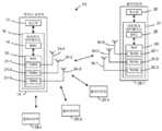
도 1은 일 실시예에 따른, AP(14)를 포함한 예시적인 WLAN(10)의 블록도이다. AP(14)는 네트워크 인터페이스(16)에 결합된 호스트 프로세서(15)를 포함한다. 네트워크 인터페이스(16)는 매체 액세스 제어(MAC) 프로세싱 유닛(18) 및 물리 계층(PHY) 프로세싱 유닛(20)을 포함한다. PHY 프로세싱 유닛(20)은 복수의 트랜시버들(21)을 포함하며, 트랜시버들(21)은 복수의 안테나들(24)에 결합된다. 3개의 트랜시버들(21) 및 3개의 안테나들(24)이 도 1에 예시되지만, AP(14)는 다른 실시예들에서 상이한 수들(예로서, 1, 2, 4, 5 등)의 트랜시버들(21) 및 안테나들(24)을 포함할 수 있다.1 is a block diagram of an
WLAN(10)은 복수의 클라이언트 국들(25)을 더 포함한다. 4개의 클라이언트 국들(25)이 도 1에 예시되지만, WLAN(10)은 다양한 시나리오들 및 실시예들에서 상이한 수들(예로서, 1, 2, 3, 5, 6 등)의 클라이언트 국들(25)을 포함할 수 있다. 클라이언트 국들(25) 중 적어도 하나(예로서, 클라이언트 국(25-1))는 적어도 장거리 통신 프로토콜에 따라 동작하도록 구성된다. 일부 실시예들에서, 클라이언트 국들(25) 중 적어도 하나(예를 들어, 클라이언트 국(25-4))는 적어도 단거리 통신 프로토콜들 중 적어도 하나에 따라 동작하도록 구성되는 단거리 클라이언트 국이다.
클라이언트 국(25-1)은 네트워크 인터페이스(27)에 결합된 호스트 프로세서(26)를 포함한다. 네트워크 인터페이스(27)는 MAC 프로세싱 유닛(28) 및 PHY 프로세싱 유닛(29)을 포함한다. PHY 프로세싱 유닛(29)은 복수의 트랜시버들(30)을 포함하고, 트랜시버들(30)은 복수의 안테나들(34)에 결합된다. 3개의 트랜시버들(30) 및 3개의 안테나들(34)이 도 1에 예시되지만, 클라이언트 국(25-1)은 다른 실시예들에서 상이한 수들(예로서, 1, 2, 4, 5 등)의 트랜시버들(30) 및 안테나들(34)을 포함할 수 있다.The client station 25 - 1 includes a
몇몇 실시예들에서, 클라이언트 국들(25-2, 25-3, 및 25-4) 중 하나, 몇몇, 또는 모두는 클라이언트 국(25-1)과 동일하거나 또는 유사한 구조를 가진다. 이들 실시예들에서, 클라이언트 국(25-1)과 동일하거나 또는 유사하게 구조화된 클라이언트 국들(25)은 동일하거나 또는 상이한 수의 트랜시버들 및 안테나들을 가진다. 예를 들면, 클라이언트 국(25-2)은 일 실시예에 따라, 단지 두 개의 트랜시버들 및 두 개의 안테나들만을 가진다.In some embodiments, one, some, or all of the client stations 25-2, 25-3, and 25-4 have the same or similar structure as the client station 25-1. In these embodiments, the same or similarly structured client stations 25 as client station 25-1 have the same or different numbers of transceivers and antennas. For example, client station 25-2 has only two transceivers and two antennas, according to one embodiment.
다양한 실시예들에서, AP(14)의 PHY 프로세싱 유닛(20)은 장거리 통신 프로토콜을 따르며 이후 설명된 포맷들을 갖는 데이터 유닛들을 생성하도록 구성된다. 트랜시버(들)(21)는 안테나(들)(24)를 통해 생성된 데이터 유닛들을 송신하도록 구성된다. 유사하게, 트랜시버(들)(24)는 안테나(들)(24)를 통해 이러한 데이터 유닛들을 수신하도록 구성된다. AP(14)의 PHY 프로세싱 유닛(20)은 다양한 실시예들에 따라, 장거리 통신 프로토콜을 따르며 이후 설명된 포맷들을 갖는 수신된 데이터 유닛들을 프로세싱하도록 구성된다.In various embodiments, the
다양한 실시예들에서, 클라이언트 디바이스(25-1)의 PHY 프로세싱 유닛(29)은 장거리 통신 프로토콜에 따르고 후술되는 포맷들을 갖는 데이터 유닛들을 생성하도록 구성된다. 트랜시버(들)(30)는 안테나(들)(34)를 통해 생성된 데이터 유닛들을 송신하도록 구성된다. 유사하게, 트랜시버(들)(30)는 안테나(들)(34)를 통해 데이터 유닛들을 수신하도록 구성된다. 클라이언트 디바이스(25-1)의 PHY 프로세싱 유닛(29)은 또한 다양한 실시예들에 따라, 장거리 통신 프로토콜에 따르며 이후 설명되는 포맷들을 갖는 수신된 데이터 유닛들을 프로세싱하도록 구성된다.In various embodiments, the
일부 실시예들에서, AP(14)는 이중 대역 구성들에서 동작하도록 구성된다. 이러한 실시예들에서, AP(14)는 동작의 단거리 및 장거리 모드들 사이에서 스위칭할 수 있다. 하나의 이러한 실시예에 따르면, 단거리 모드에서 동작할 때, AP(14)는 단거리 통신 프로토콜들 중 하나 이상에 따르는 데이터 유닛들을 송신 및 수신한다. 장거리 모드에서 동작할 때, AP(14)는 장거리 통신 프로토콜에 따르는 데이터 유닛들을 송신 및 수신한다. 유사하게, 클라이언트 국(25-1)은 일부 실시예들에 따라, 이중 주파수 대역 동작을 할 수 있다. 이들 실시예들에서, 클라이언트 국(25-1)은 동작의 단거리 및 장거리 모드들 사이에서 스위칭할 수 있다. 다른 실시예들에서, AP(14) 및/또는 클라이언트 국(25-1)은 장거리 통신 프로토콜에 의해 장거리 동작들에 대해 정의된 상이한 저 주파수 대역들 사이에서 스위칭할 수 있는 이중 대역 디바이스이다. 또 다른 실시예에서, AP(14) 및/또는 클라이언트 국(25-1)는 단지 하나의 장거리 주파수 대역에서만 동작하도록 구성되는 단일 대역 디바이스이다.In some embodiments, the
또 다른 실시예들에서, 클라이언트 국(25-1)은 다른 상응하는 PHY 모드들에 의해 상이한 영역들에서 동작할 수 있는 이중 모드 디바이스이다. 예를 들어, 하나의 그러한 실시예에서, 클라이언트 국(25-1)은 제 1 영역에서 동작할 때 정상 모드 PHY를 이용하고, 제 2 영역(예를 들어, 더 적게 이용 가능한 스펙트럼을 갖는 영역)에서 동작할 때 저 대역폭 모드 PHY를 이용하도록 구성된다. 일 실시예에서, 클라이언트 국(25-1)은 송신기 및 수신기의 저 대역폭 모드 및 정상 모드 기저대역 신호 처리 사이에서 스위칭함으로써, 그리고 각각의 모드에 적용 가능한 요건들(예를 들어, 송신기에서의 스펙트럼 마스크 요건들, 수신기에서의 인접 채널 간섭 요건들 등)을 충족시키기 위해 디지털 및 아날로그 필터들을 스위칭함으로써 상이한 영역들 내의 정상 모드 및 저 대역폭 모드 사이에서 스위칭할 수 있다. 그러나, 클록 속도와 같은 하드웨어 설정들은 실시예에서, 저 대역폭 모드와 정상 모드 사이에서 스위칭할 때 변경되지 않는다.In yet other embodiments, client station 25-1 is a dual mode device capable of operating in different areas with other corresponding PHY modes. For example, in one such embodiment, the client station 25 - 1 uses a normal mode PHY when operating in a first region, and a second region (eg, an region with less available spectrum). It is configured to use the low bandwidth mode PHY when operating in In one embodiment, the client station 25-1 switches between low bandwidth mode and normal mode baseband signal processing of the transmitter and receiver, and the requirements applicable to each mode (e.g., spectrum at the transmitter). It is possible to switch between normal mode and low bandwidth mode in different regions by switching digital and analog filters to meet mask requirements, adjacent channel interference requirements at the receiver, etc.). However, hardware settings such as clock speed, in an embodiment, do not change when switching between low bandwidth mode and normal mode.
하나의 예시적인 실시예에서, 클라이언트 국(25-1)은 미국에서 정상 모드 PHY(예를 들어, 2 MHz 및 더 넓은 채널들에 대한)를 이용하고 유럽 및/또는 일본에서 저 대역폭 모드(예를 들어, 1 MHz 채널들에 대한)를 이용하는 이중 모드 디바이스이다. 동일한 클록 속도가 전세계적으로 사용되며, 이러한 실시예에서, 상이한 IDFT(inverse discrete Fourier transform) 크기들은 상이한 대역폭들(예를 들어, 2 MHz 또는 더 넓은 대역폭 미국 채널들에 대한 64-포인트 또는 더 큰 IDFT, 및 1 MHz 유럽/일본 채널들에 대한 32-포인트 IDFT)의 신호들을 생성하기 위해 이용된다. 이러한 실시예들의 일부에서, 저 대역폭 모드는 또한 미국에서 제어 PHY에 사용된다.In one exemplary embodiment, the client station 25-1 uses a normal mode PHY (eg, for 2 MHz and wider channels) in the United States and a low bandwidth mode (eg, for Europe and/or Japan). For example, it is a dual mode device (for 1 MHz channels). The same clock rate is used worldwide, and in this embodiment, different inverse discrete Fourier transform (IDFT) sizes are used for different bandwidths (eg, 64-point or larger for 2 MHz or wider bandwidth US channels). IDFT, and 32-point IDFT for 1 MHz Europe/Japan channels). In some of these embodiments, a low bandwidth mode is also used for the control PHY in the United States.
다른 예시적인 실시예에서, 클라이언트 국(25-1)은 미국에서 정상 모드 PHY(예를 들어, 2 MHz 및 더 넓은 채널들에 대한) 및 저 대역폭 모드 PHY(예를 들어, 1 MHz 대역폭을 갖는 제어 모드 신호들에 대한)를 이용하고, 유럽 및/또는 일본에서 저 대역폭 모드 PHY(예를 들어, 1 MHz 채널들에 대한)만을 이용하는 이중 모드 디바이스이다. 동일한 클록 속도는 전세계적으로 사용되며, 이러한 실시예에서, 상이한 IDFT 크기들은 상이한 대역폭들(예를 들어, 2 MHz 또는 더 넓은 대역폭 미국 채널들에 대한 64-포인트 또는 더 큰 IDFT, 및 1 MHz 미국 제어 모드 신호들 및 1 MHz 유럽/일본 채널들에 대한 32-포인트 IDFT)의 신호들을 생성하기 위해 사용된다.In another exemplary embodiment, the client station 25-1 is a normal mode PHY (eg, for 2 MHz and wider channels) and a low bandwidth mode PHY (eg, having a 1 MHz bandwidth) in the United States. It is a dual mode device that uses only the low bandwidth mode PHY (eg, for 1 MHz channels) in Europe and/or Japan). The same clock rate is used worldwide, and in this embodiment, different IDFT sizes are used for different bandwidths (eg, 64-point or larger IDFT for 2 MHz or wider bandwidth US channels, and 1 MHz US channels). control mode signals and signals of a 32-point IDFT for 1 MHz Europe/Japan channels).
일부 실시예들에서, 클라이언트 국(25-1)과 같은 디바이스들은 가장 작은 대역폭 정상 모드 데이터 유닛 또는 저 대역폭 모드 데이터 유닛을 생성하든 동일한 크기 IDFT를 (일정한 클록 속도)로 사용한다. 예를 들어, 일 실시예에서, 64-포인트 IDFT는 2 MHz 정상 모드 데이터 유닛 및 1 MHz 저 대역폭 모드 데이터 유닛 둘 모두를 생성하기 위해 사용되며, 적절한 톤들은 후자의 경우에 제로 아웃된다. 이러한 실시예들에 대한 일부 시나리오들에서, 필터들은 더 넓은(예를 들어, 2 MHz) 채널에 대한 스펙트럼 마스크 요건들을 여전히 충족하는 동안, PHY 모드들 사이에서 변경할 때 작동 중에(on the fly) 변경될 필요가 없다. 다른 시나리오들에서, 송신된 저 대역폭 모드 신호는 더 넓은 대역폭에 상응하는 IDFT 크기를 사용하여 송신될지라도 보다 엄격한, 하부 대역폭 스펙트럼 마스크를 충족하도록 요구된다.In some embodiments, devices such as client station 25-1 use the same size IDFT (constant clock rate) whether generating the smallest bandwidth normal mode data unit or low bandwidth mode data unit. For example, in one embodiment, a 64-point IDFT is used to generate both a 2 MHz normal mode data unit and a 1 MHz low bandwidth mode data unit, and the appropriate tones are zeroed out in the latter case. In some scenarios for these embodiments, filters change on the fly when changing between PHY modes while still meeting spectral mask requirements for a wider (eg, 2 MHz) channel. it doesn't have to be In other scenarios, the transmitted low bandwidth mode signal is required to meet a more stringent, lower bandwidth spectral mask, even if transmitted using an IDFT size corresponding to a wider bandwidth.
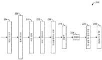
도 2는 일 실시예에 따른 정상 모드 데이터 유닛들을 생성하는 예시적인 PHY 프로세싱 유닛(100)의 송신 부분의 블록도이다. 도 1을 참조하면, AP(14)의 PHY 프로세싱 유닛(20) 및 클라이언트 국(25-1)의 PHY 프로세싱 유닛(29)은 일 실시예에서, PHY 프로세싱 유닛(100)과 각각 유사하거나 동일하다. PHY 프로세싱 유닛(100)은 일 실시예에 따라, 1들 또는 0들의 긴 시퀀스들의 발생들을 감소시키기 위해 정보 비트 스트림을 일반적으로 스크램블링하는 스크램블러(102)를 포함한다. 인코더 파서(104)는 스크램블러(102)에 결합된다. 인코더 파서(208)는 정보 비트 스트림을 하나 이상의 FEC 인코더들(106)에 상응하는 하나 이상의 인코더 입력 스트림들로 역다중화한다.2 is a block diagram of a transmit portion of an exemplary
2개의 FEC 인코더(106)가 도 2에 도시되지만, 다양한 다른 실시예들 및/또는 시나리오들에서, 상이한 수들의 FEC 인코더들이 포함되며/되거나, 상이한 수들의 FEC 인코더들이 병렬로 동작한다. 예를 들면 일 실시예에 따르면, PHY 프로세싱 유닛(100)은 4개의 FEC 인코더들(106)을 포함하며, FEC 인코더들(106) 중 1, 2, 3, 또는 4개는 특정한 변조 및 코딩 기법(MCS), 대역폭, 및 공간 스트림들의 수에 의존하여 동시에 동작한다. 각각의 FEC 인코더(106)는 대응하는 인코딩된 스트림을 생성하기 위해 대응하는 입력 스트림을 인코딩한다. 일 실시예에서, 각각의 FEC 인코더(106)는 BCC(binary convolutional coder)를 포함한다. 다른 실시예에서, 각각의 FEC 인코더(106)는 BCC에 이어 펑처링 블록(puncturing block)을 포함한다. 다른 실시예에서, 각각의 FEC 인코더(106)는 LDPC(low density parity check) 인코더를 포함한다.Although two
스트림 파서(108)는 컨스텔레이션 포인트들/심볼들로의 개별 인터리빙 및 매핑을 위해 하나 이상의 인코딩된 스트림들을 하나 이상의 공간 스트림들(예를 들어, 도 2에 도시된 예시적인 PHY 프로세싱 유닛(100)에서 4개의 스트림)로 파싱한다. 일 실시예에서, 스트림 파서(108)는 IEEE 802.11n 통신 프로토콜에 따라 동작하여, 이하의 수학식이 만족된다:The
[수학식 1][Equation 1]

여기에서s는NSS 공간 스트림들의 각각에 대한 컨스텔레이션 포인트에서의 단일 축에 할당된 코딩 비트들의 수이며,NBPSCS는 서브캐리어 당 비트들의 수이다. 각각의 FEC 인코더(106)에 대해(BCC이든지 LDPC이든지),s코딩 비트들의 연속적인 블록들은 일 실시예에서, 라운드 로빈 방식으로 상이한 공간 스트림들에 할당된다. FEC 인코더들(106)의 세트가 2개 이상의 BCC 인코더들을 포함하는 일부 실시예들에서, 개별 FEC 인코더들(106)의 출력들은 각각의 라운드 로빈 사이클 동안 교번 방식으로 사용되며, 즉 초기에 제 1 FEC 인코더(106)로부터의S 비트들은NSS 공간 스트림들으로 공급되고, 그 다음 제 2 FEC 인코더(106)로부터의S 비트들은NSS 공간 스트림들으로 공급되는 등등이며, 여기서:wheres is the number of coding bits allocated to a single axis at the constellation point for each of theNSSspatial streams, and NBPSCS is the number of bits per subcarrier. For each FEC encoder 106 (whether BCC or LDPC),consecutive blocks of s coded bits are assigned to different spatial streams in a round robin manner, in one embodiment. In some embodiments where the set of
[수학식 2][Equation 2]
S=NSSxsS =NSS xs
NSS 공간 스트림들 각각에 상응하면, 인터리버(110)는 인접한 잡음 비트들의 긴 시퀀스들이 수신기에서 디코더에 들어가는 것을 방지하기 위해 공간 스트림의 비트들을 인터리빙한다(즉, 비트들의 순서를 변경함). 보다 구체적으로, 인터리버(110)는 주파수 도메인에서 또는 시간 도메인에서 비-인접한 위치들로 인접한 코딩 비트들을 매핑한다. 인터리버(110)는 실시예에서, 파라미터들Ncol,Nrow, 및Nrot(즉, 각각 컬럼들의 수, 로우들의 수, 및 주파수 회전 파라미터)이 장거리, 정상 모드 데이터 유닛들의 대역폭에 기초한 적절한 값들임을 제외하고, IEEE 802.11n 통신 프로토콜에 따라 동작한다(즉, 각각의 데이터 스트림에서의 두 개의 주파수 치환들, 및 상이한 스트림들 상에서 상이하게 비트들을 순환적으로 시프트하기 위한 제 3 치환).Corresponding to each of the NSS spatial streams, the
또한 각각의 공간 스트림에 대응하여, 컨스텔레이션 매퍼(112)는 비트들의 인터리빙된 시퀀스를 OFDM 심볼의 상이한 서브캐리어들/톤들에 상응하는 컨스텔레이션 포인트들에 매핑한다. 보다 구체적으로, 각각의 공간 스트림에 대해, 컨스텔레이션 매퍼(112)는 실시예에서, 길이 log2(M)의 모든 비트 시퀀스를M개의 컨스텔레이션 포인트들 중 하나로 변환한다. 컨스텔레이션 매퍼(112)는 이용되는 MCS에 의존하여 상이한 수들의 컨스텔레이션 포인트들을 핸들링한다. 실시예에서, 컨스텔레이션 매퍼(112)는M = 2, 4, 16, 64, 256, 및 1024를 핸들링하는 직교 진폭 변조(QAM) 매퍼이다. 다른 실시예들에서, 컨스텔레이션 매퍼(112)는 세트 {2, 4, 16, 64, 256, 1024}로부터 적어도 2개의 값들의 상이한 서브세트들과 같은M에 상응하는 상이한 변조 방식들을 다룬다.Also corresponding to each spatial stream, the
실시예에서, 공간-시간 블록 코딩(space-time block coding: STBC) 유닛(114)은 하나 이상의 공간 스트림들에 대응하는 컨스텔레이션 포인트들을 수신하며 수(NSTS)의 공간-시간 스트림들로 공간 스트림들을 확산시킨다. 몇몇 실시예들에서, STBC(114)는 생략된다. 순환 시프트 다이버시티(cyclic shift diversity: CSD) 유닛들(116)이 STBC 유닛(114)에 결합된다. CSD 유닛들(116)은 의도되지 않은 빔형성을 방지하기 위해 순환 시프트들을 하나를 제외한 모든 공간 시간 스트림들(하나 이상의 공간 시간 스트림인 경우)에 삽입한다. 설명의 용이성을 위해, CSD 유닛들(116)에 대한 입력들은 STBC 유닛(114)이 생략되는 실시예들에서도 공간 시간 스트림들로 지칭된다.In an embodiment, a space-time block coding (STBC)
공간 매핑 유닛(120)은NSTS공간-시간 스트림들을NTX 송신 체인들에 매핑한다. 다양한 실시예들에서, 공간 매핑은 1) 각각의 공간 시간 스트림으로부터의 컨스텔레이션 포인트들이 송신 체인들 위에 직접 매핑되는 직접 매핑(즉, 1 대 1 매핑); 2) 모든 공간-시간 스트림들로부터의 컨스텔레이션 포인트들의 벡터들이 입력들을 송신 체인들에 생성하기 위해 매트릭스 곱셈을 통해 확장되는 공간 확장; 및 3) 공간-시간 스트림들의 모두로부터의 컨스텔레이션 포인트들의 각각의 벡터가 입력들을 송신 체인들에 생성하기 위해 조향 벡터들의 매트릭스에 곱해지는 빔형성 중 하나 이상을 포함한다. 공간 매핑 유닛(120)의 각각의 출력은 송신 체인에 대응하며, 공간 매핑 유닛(120)의 각각의 출력은 컨스텔레이션 포인트들의 블록을 시간-도메인 신호로 변환하는 IDFT 산출 유닛(122)(예로서, 역 고속 푸리에 변환(inverse fast Fourier transform: IFFT) 산출 유닛)에 의해 동작된다. IDFT 유닛들(122)의 출력들은 실시예에서 OFDM 심볼의 원형 확장인, 보호 구간(guard interval: GI) 부분을 OFDM 심볼들에 첨부하며, 스펙트럼 지연을 증가시키기 위해 OFDM 심볼들의 에지들을 평활화하는 GI 삽입 및 윈도우잉 유닛들(124)에 제공된다. GI 삽입 및 윈도우잉 유닛들(124)의 출력들은 신호들을 아날로그 신호들로 변환하며 신호들을 송신을 위한 RF 주파수들로 상향 변환하는 아날로그 및 라디오 주파수(RF) 유닛들(126)에 제공된다. 신호들은 다양한 실시예들 및/또는 시나리오들에서, 2 MHz, 4 MHz, 8 MHz, 또는 16 MHz 대역폭 채널(예로서, 각각 유닛(122)에서 64-, 128-, 256-, 또는 512-포인 IDFT트에 대응하며, IDFT 크기에 관계없이 일정한 클록 레이트를 이용하는)에서 송신된다. 다른 실시예들에서, 다른 적절한 채널 대역폭들(및/또는 IDFT 크기들)이 이용된다. 정상 모드에 대응하는 장거리 데이터 유닛들은 2012년 1월 6일에 출원되며, "Physical Layer Frame Format for Long Range WLAN"이라는 명칭의, 미국 특허 출원 번호 제13/359,336호에 보다 상세히 논의되며, 이것은 여기에서 전체적으로 참조로서 통합된다.
저 대역폭 모드 통신들은 일반적으로 확장된 범위 통신들을 지원하는 감도 이득을 갖는 정상 모드 통신들보다 더 견고하다. 예를 들면, 정상 모드 데이터 유닛들을 생성하기 위해 정상 모드가 64-포인트 IDFT(예로서, 2 MHz 대역폭 신호에 대해)를 이용하며, 저 대역폭 모드 데이터 유닛들을 생성하기 위해 저 대역폭 모드가 32-포인트 IDFT(예로서, 1 MHz 대역폭 신호에 대해)를 이용하는 실시예에서, 저 대역폭 모드는 대략 3 dB의 감도 이득을 제공한다. 또 다른 예로서, 정상 모드 데이터 유닛들을 생성하기 위해 정상 모드가 64-포인트 IDFT(예로서, 2 MHz 대역폭 신호에 대해)를 이용하며, 저 대역폭 모드 데이터 유닛들을 생성하기 위해 저 대역폭 모드가 16-포인트 IDFT(예로서, 0.5 MHz 대역폭 신호에 대해)를 이용하는 실시예에서, 저 대역폭 모드는 대략 6 dB의 감도 이득을 제공한다. 게다가, 몇몇 실시예들에서, 저 대역폭 모드는 데이터 레이트를 추가로 감소시키기 위해 데이터 유닛의 적어도 몇몇 필드들로 비트들의 리던던시 또는 반복을 도입한다. 예를 들어, 다양한 실시예들 및/또는 시나리오들에서, 저 대역폭 모드는 후술되는 하나 이상의 반복 및 코딩 방식들에 따라 리던던시를 저 대역폭 모드 데이터 유닛의 데이터 부분 및/또는 신호 필드에 도입한다. 저 대역폭 모드가 예를 들면, 비트들의 2x 반복을 포함하는 실시예에서, 추가 3 dB의 감도 이득이 획득될 수 있다. 또한, 몇몇 실시예들에서, 저 대역폭 모드는 정상 모드의 최저 데이터 레이트 MCS에 따라, 또는 정상 모드의 최저 데이터 레이트 MCS보다 작은 MCS에 따라 OFDM 심볼들을 생성함으로써 감도를 개선한다. 일 예로서, 일 실시예에서, 정상 모드에서의 데이터 유닛들은 고차 MCS들이 더 높은 데이터 레이트들에 상응하는 상태에서, MCS0(1/2의 이진 위상 시프트 키잉(binary phase shift keying: BPSK) 변조 및 코딩 레이트)와 같은 MCS 세트로부터 MCS9(5/6의 직교 진폭 변조(quadrature amplitude modulation: QAM) 및 코딩 레이트)로 선택되는 특정 MCS에 따라 생성된다. 하나의 그러한 실시예에서, 저 대역폭 모드 데이터 유닛들은 MCS0에 의해 정의되는 바와 같은 변조 및 코딩을 사용하여 생성된다. 대안적인 실시예에서, MCS0는 저 대역폭 모드 데이터 유닛들만을 위해 예약되고, 정상 모드 데이터 유닛들에 사용될 수 없다.Low bandwidth mode communications are generally more robust than normal mode communications with a sensitivity gain that supports extended range communications. For example, normal mode uses a 64-point IDFT (eg, for a 2 MHz bandwidth signal) to generate normal mode data units, and low bandwidth mode uses 32-point to generate low bandwidth mode data units. In an embodiment using IDFT (eg, for a 1 MHz bandwidth signal), the low bandwidth mode provides a sensitivity gain of approximately 3 dB. As another example, the normal mode uses a 64-point IDFT (eg, for a 2 MHz bandwidth signal) to generate normal mode data units, and the low bandwidth mode uses a 16-point IDFT (eg, for a 2 MHz bandwidth signal) to generate low bandwidth mode data units. In an embodiment using a point IDFT (eg, for a 0.5 MHz bandwidth signal), the low bandwidth mode provides a sensitivity gain of approximately 6 dB. Furthermore, in some embodiments, the low bandwidth mode introduces redundancy or repetition of bits into at least some fields of the data unit to further reduce the data rate. For example, in various embodiments and/or scenarios, the low bandwidth mode introduces redundancy into the data portion and/or signal field of the low bandwidth mode data unit according to one or more iteration and coding schemes described below. In embodiments where the low bandwidth mode includes, for example, 2x repetition of bits, an additional 3 dB of sensitivity gain may be obtained. Also, in some embodiments, the low bandwidth mode improves sensitivity by generating OFDM symbols according to the lowest data rate MCS of the normal mode, or according to an MCS that is less than the lowest data rate MCS of the normal mode. As an example, in one embodiment, data units in normal mode are subjected to binary phase shift keying (BPSK) modulation of 1/2 and MCS0, with higher order MCSs corresponding to higher data rates. is generated according to a specific MCS selected from a set of MCSs such as (coding rate) and MCS9 (quadrature amplitude modulation (QAM) and coding rate of 5/6). In one such embodiment, the low bandwidth mode data units are generated using modulation and coding as defined by MCS0. In an alternative embodiment, MCS0 is reserved for low bandwidth mode data units only and cannot be used for normal mode data units.
도 3 내지 도 5는 다양한 실시예들에 따라, 저 대역폭 모드 데이터 유닛들을 생성하기 위한 예시적인 PHY 프로세싱 유닛들의 송신 부분들의 블록도들이다. 도 1을 참조하면, AP(14)의 PHY 프로세싱 유닛(20) 및 클라이언트 국(25-1)의 PHY 프로세싱 유닛(29)은 각각 다양한 실시예들에서, 도 3 내지 도 5에 도시된 PHY 프로세싱 유닛들 중 임의의 하나와 유사하거나 또는 동일하다. 몇몇 실시예들에서, 도 3 내지 도 5의 PHY 프로세싱 유닛들은 도 2의 PHY 프로세싱 유닛(100)과 동일한 하드웨어에 대응하지만, 상이한 신호 프로세싱 동작들은 정상 모드 또는 저 대역폭 모드 데이터 유닛들이 생성되는지에 의존하여 하드웨어 내에서 이용된다.3-5 are block diagrams of transmit portions of example PHY processing units for generating low bandwidth mode data units, in accordance with various embodiments. Referring to FIG. 1 ,
도 3의 PHY 프로세싱 유닛(150)은 실시예에서, 도 2의 스크램블러(102)와 유사한 스크램블러(152)를 포함한다. 스크램블러(152)는 하나 이상의 FEC 인코더들(154)에 결합되며, 이것은 실시예에서 도 2의 FEC 인코더(106)와 유사하다. PHY 프로세싱 유닛(150)이 둘 이상의 FEC 인코더들(154)을 포함하는 실시예에서, 도 2의 인코더 파서(104)와 유사한 인코더 파서(도시되지 않음)가 스크램블러(152) 및 FEC 인코더들(154) 사이에서 결합된다.The
스트림 파서(158)는 FEC 인코더(들)(154)의 출력(들)에 결합된다. 스트림 파서(158)는 상기 식 1 및 식 2에 대한 관련 파라미터들(예로서,NBPSCS 및NSS)이 저 대역폭 모드 시스템 파라미터들(단지 하나의 공간 스트림이 저 대역폭 모드 데이터 유닛들에 대해 허용된다면NSS= 1)에 일치한다는 점을 제외하고, 실시예에서, 도 2의 스트림 파서(108)와 유사하다(예로서, 상기 식 1 및 식 2가 만족되는). 스트림 파서(158)는 인터리버들(160)에 결합된다. 인터리버들(160)은 파라미터들(Ncol,Nrow, 및Nrot)이 저 대역폭 데이터 유닛들의 대역폭에 기초한 적절한 값들이라는 점을 제외하고, 실시예에서, 도 2의 인터리버들(110)과 유사하다. 예를 들면, 최저 대역폭 정상 모드 데이터 유닛들이 64-포인트 IDFT들을 사용하여 생성된 2 MHz 데이터 유닛들이며, 저 대역폭 모드 데이터 유닛들이 32-포인트 IDFT들을 사용하여 생성되며, 24개의 OFDM 데이터 톤들을 가진 1 MHz 데이터 유닛들인 다양한 실시예들에서, 다음의 3개의 옵션들 중 하나가 구현된다:The
[수학식 3][Equation 3]
1)Ncol = 12,Nrow=2 xNBPSCS1)Ncol = 12,Nrow= 2 xNBPSCS
[수학식 4][Equation 4]
2)Ncol = 8,Nrow=3 xNBPSCS2)Ncol = 8,Nrow= 3 xNBPSCS
[수학식 5][Equation 5]
3)Ncol = 6,Nrow=4 xNBPSCS3)Ncol = 6,Nrow= 4 xNBPSCS
및Nrot는 {2, 3, 4, 5, 6, 7, 8} 중 하나이다. 예를 들면, 하나의 특정한 실시예에서, 식 4가 만족되며Nrot = 2이다. 또 다른 예로서, 최저 대역폭 정상 모드 데이터 유닛들이 64-포인트 IDFT들을 사용하여 생성된 2 MHz 데이터 유닛들이며, 저 대역폭 모드 데이터 유닛들이 16-포인트 IDFT들을 사용하여 생성되며 12개의 OFDM 데이터 톤들을 가진 0.5 MHz 데이터 유닛들인 다양한 실시예들에서, 다음의 두 개의 옵션들 중 하나가 구현된다:andNrot is one of {2, 3, 4, 5, 6, 7, 8}. For example, in one particular embodiment, Equation 4 is satisfied andNrot =2. As another example, the lowest bandwidth normal mode data units are 2 MHz data units generated using 64-point IDFTs, and the low bandwidth mode data units are generated using 16-point IDFTs and 0.5 with 12 OFDM data tones. In various embodiments that are MHz data units, one of the following two options is implemented:
[수학식 6][Equation 6]
1)Ncol = 6,Nrow=2 xNBPSCS1)Ncol = 6,Nrow= 2 xNBPSCS
[수학식 7][Equation 7]
2)Ncol = 4,Nrow=3 xNBPSCS2)Ncol = 4,Nrow= 3 xNBPSCS
및Nrot는 [2, 3, 4, 5] 중 하나이다.andNrot is one of [2, 3, 4, 5].
각각의 공간 스트림에 대응하여, 컨스텔레이션 매퍼(162)는 OFDM 심볼의 상이한 서브캐리어들/톤들에 대응하는 컨스텔레이션 포인트들에 비트들의 인터리빙된 시퀀스를 매핑한다. 컨스텔레이션 매퍼들(162)은 실시예에서, 도 2의 컨스텔레이션 매퍼들(112)과 유사하다.Corresponding to each spatial stream,
상기 설명된 임의의 MCS 제약들(예로서, 저 대역폭 모드 데이터 유닛들은 단지 최저 MCS를 사용하기 위해서만 허용되는 등) 외에, 또는 그 대신에, 다양한 실시예들에서, 저 대역폭 모드 데이터 유닛들에 대한 허용된 MCS들은 다음의 식들을 만족시키는 MCS들이다:In addition to or instead of any of the MCS constraints described above (eg, low bandwidth mode data units are only allowed to use the lowest MCS, etc.), in various embodiments, Allowed MCSs are those that satisfy the following equations:
[수학식 8][Equation 8]
NCBPS/NES =mNCBPS /NES =m
[수학식 9][Equation 9]
NDBPS/NES =nNDBPS /NES =n
[수학식 10][Equation 10]
mod(NCBPS/NES,DR) = 0mod(NCBPS /NES ,DR ) = 0
[수학식 11][Equation 11]
R =NR/DRR =NR /DR
여기서NCBPS는 심볼 당 코딩 비트들의 수이고,NDBPS는 심볼 당 코딩되지 않은 비트들의 수이며,NES는 BCC 인코더들의 수이고,m및n은 정수들이고,R은 코딩 레이트이며,DR은 코딩 레이트의 분모이다(즉, R = 1/2이면,DR = 2, R = 2/3이면,DR = 3, R = 3/4이면,DR = 4, 및 R = 5/6이면,DR = 5). 실시예에서,NES은 항상 저 대역폭 모드 데이터 유닛들에 대해 1과 같다(즉, 하나의 공간 스트림 및 하나의 BCC 인코더가 저 대역폭 모드에서 사용된다). 다른 실시예들에서,NES는 저 대역폭 모드 데이터 유닛들에 대해 1보다 큰 적절한 수이다.whereNCBPS is the number of coded bits per symbol,NDBPS is the number of uncoded bits per symbol,NES is the number of BCC encoders,m andn are integers,R is the coding rate, andDR is is the denominator of the coding rate (i.e., if R = 1/2, thenDR = 2, if R = 2/3, thenDR = 3, if R = 3/4, thenDR = 4, and R = 5/6.) , thenDR = 5). In an embodiment,NES is always equal to 1 for low bandwidth mode data units (ie, one spatial stream and one BCC encoder are used in low bandwidth mode). In other embodiments,NESis a suitable number greater than 1 for low bandwidth mode data units.
실시예에서, STBC 유닛(164)(예로서, 도 2의 STBC 유닛(114)과 유사한)은 하나 이상의 공간 스트림들에 대응하는 컨스텔레이션 포인트들을 수신하며 공간 스트림들을 다수의 공간-시간 스트림들로 확산시킨다. 복수의 CSD 유닛들(166)(예로서, 도 2의 CSD 유닛들(116)과 유사한)은 STBC 유닛(164)에 결합되며, 이것은 결과적으로, 공간 매핑 유닛(170)(예로서, 도 2의 공간 매핑 유닛(120)과 유사한)에 결합된다. 공간 매핑 유닛(170)의 각각의 출력은 송신 체인에 대응하며, 공간 매핑 유닛(120)의 각각의 출력은 IDFT 유닛(172)에 의해 동작된다. IDFT 유닛들(172)은 실시예에서 도 2의 IDFT 유닛들(122)과 유사하며, IDFT 유닛들(122)과 동일한 클록 레이트를 사용하지만, 임의의 정상 모드 데이터 유닛들보다 작은 크기 IDFT를 사용한다. 예를 들면, 정상 모드 데이터 유닛들이 64-포인트 이상의 IDFT들을 사용하여 생성되는 일 실시예에서, 저 대역폭 모드 데이터 유닛들은 32-포인트 IDFT들을 사용하여 생성된다. 정상 모드 데이터 유닛들이 64-포인트 이상의 IDFT들을 사용하여 생성되는 대안적인 실시예에서, 저 대역폭 모드 데이터 유닛들은 16-포인트 IDFT들을 사용하여 생성된다. 정상 모드 데이터 유닛들이 64-포인트 이상의 IDFT들을 사용하여 생성되는 또 다른 대안적인 실시예에서, 저 대역폭 모드 데이터 유닛들은 저 대역폭 모드 내에서의 두 개의 PHY 서브-모드들 중 어떤 것이 선택되는지에 의존하여 16-포인트 또는 32-포인트 IDFT를 사용하여 생성된다.In an embodiment, STBC unit 164 (eg, similar to
IDFT 유닛들(172)의 출력들은 GI 삽입 및 윈도우잉 유닛들(174)(예로서, 도 2의 GI 삽입 및 윈도우잉 유닛들(124)과 유사한)에 제공되며, GI 삽입 및 윈도우잉 유닛들(172)의 출력들은 아날로그 및 RF 유닛들(176)(예로서, 도 2의 아날로그 및 RF 유닛들(126)과 유사한)에 제공된다. 일 실시예에서, 생성된 저 대역폭 모드 데이터 유닛들은 그 후 저 대역폭 모드 주파수 대역에서 송신된다. 정상 모드 송신들이 2 MHz 이상의 대역폭(예로서, 4 MHz, 8 MHz 등) 채널들을 이용하는 일 실시예에서, 저 대역폭 모드 송신들을 위한 주파수 대역은 1 MHz이다. 다른 이러한 실시예들에서, 0.5 MHz 또는 최소 정상 모드 채널 대역폭보다 작은 또 다른 적절한 대역폭이 이용된다.The outputs of the
도 3의 예시적인 PHY 프로세싱 유닛(150)이 다수의 공간 스트림들(하나는 각각의 인터리버(160) 및 컨스텔레이션 매퍼(162)를 위한 것임)을 포함하지만, 저 대역폭 모드는 다른 실시예들에서 단지 단일 공간 스트림만을 이용한다. 예를 들면, 저 대역폭 모드는 단지 하나의 공간 스트림이 이용되는 MCS(예로서, 상술된 MCS0)로 제한된다. 이들 실시예들 중 몇몇에서, 스트림 파서(158)는 생략되거나 또는 이용되지 않는다. 게다가, STBC 유닛(164) 및/또는 CSD 유닛들(166)은 몇몇 실시예들에서 생략된다. 또한, FEC 인코더(154)가 BCC 인코더가 아니라 LDPC 인코더인 일 실시예에서, 인터리버들(160)이 생략된다. 실시예에서, 정상 모드를 위해 사용된 동일한 LDPC 패리티 매트릭스 및 파라미터들이 또한 저 대역폭 모드를 위해 사용되며, 펑처링/단축/패딩 절차가 저 대역폭 모드에 대응하는NCBPS및NDBPS(각각, 심볼 당 코딩된 데이터 비트들 및 심볼 당 코딩되지 않은 데이터 비트들의 수)의 값들을 이용한다. 몇몇 실시예들에서, 저 대역폭 모드에서 사용되는 패딩 절차들은 그 개시가 여기에 전체적으로 참조로서 통합되는, 2012년 2월 3일에 출원된, "Control Mode PHY for WLAN"이라는 명칭의, 미국 출원 번호 제13/366,064호에 설명된 임의의 이러한 절차들에 대응한다.Although the example
도 4 및 도 5는 데이터 레이트를 감소시키며 수신기 감도를 증가시키기 위해 반복을 사용하는 실시예들에서 저 대역폭 모드 데이터 유닛들을 생성하기 위한 예시적인 PHY 프로세싱 유닛들의 송신 부분들을 예시한다. 설명의 용이함을 위해, 유닛들이 몇몇 실시예들에서 포함될지라도 특정 유닛들은 도 4 및 도 5에 도시되지 않는다. 예를 들면, PHY 프로세싱 유닛들의 각각은 다양한 실시예들에서, 스크램블러를 포함하며, 따라서 도 4 및 도 5에 묘사된 송신 흐름들로 입력된 정보 비트들은 스크램블링된 비트들이다. 몇몇 실시예들에서, 저 대역폭 모드는 단지 BPSK 변조를 갖고 및/또는 단일 공간-시간 스트림을 가진 도 4 또는 도 5의 반복만을 사용하며, 그렇지 않다면 반복을 사용하지 않는다(예로서, 도 3의 예시적인 PHY 프로세싱 유닛(150)에서처럼).4 and 5 illustrate transmit portions of example PHY processing units for generating low bandwidth mode data units in embodiments that use repetition to decrease data rate and increase receiver sensitivity. For ease of explanation, specific units are not shown in FIGS. 4 and 5 although units are included in some embodiments. For example, each of the PHY processing units, in various embodiments, includes a scrambler, so that the information bits input to the transmission flows depicted in FIGS. 4 and 5 are scrambled bits. In some embodiments, the low bandwidth mode has only BPSK modulation and/or uses only a repetition of FIG. 4 or FIG. 5 with a single space-time stream, otherwise no repetition (eg, of FIG. 3 ). as in the example PHY processing unit 150).
도 4는 예시적인 PHY 프로세싱 유닛(200)이 비트들을 컨스텔레이션 심볼들에 매핑하기 전에, BCC-인코딩된 비트들의 반복을 이용한 저 대역폭 모드 데이터 유닛들을 생성하는 실시예를 예시한다. BCC 인코더(204)는 정보 비트들을 받아들이며 BCC-인코딩된 비트들을 블록 인코더(206)에 출력한다. 블록 인코더(206)는 다양한 실시예들에서, 비트-레벨 반복(예로서, 2x 반복을 위한 [b1 b1, b2 b2, …]) 또는 블록-레벨 반복(예로서, 블록 크기(12)를 갖고 2x 반복을 위한 [b1…b12, b1…b12, b13…b24, b13…b24, …])을 제공한다. 일 예시적인 실시예에서, 2x 반복(레이트 1/2 블록 코딩)이 사용된다. 또 다른 예시적인 실시예에서, 4x 반복(레이트 1/4 블록 코딩)이 사용된다. 블록 인코더(206) 출력은 생성된 OFDM 심볼의 피크-대-평균 전력비(peak-to-average power ratio: PAPR)를 감소시키기 위해 선택된 비트들(예로서, 모든 다른 비트)의 부호 또는 극성을 변경하는 비트 플립 유닛(210)에 결합한다. 몇몇 실시예들에서, 비트 플립 유닛(210)은 PHY 프로세싱 유닛(200)에 포함되지 않는다.4 illustrates an embodiment in which the example
비트 플립 유닛(210)의(또는 유닛(210)이 생략된다면, 블록 인코더(206)의) 출력은 BCC 인터리버(212)에 결합된다. BCC 인터리버(212)는 실시예에서, 도 3의 인터리버(160)와 유사하다. 몇몇 실시예들에서, BCC 인터리버(212)는 PHY 프로세싱 유닛(200)에 포함되지 않는다. BCC 인터리버(212)의(또는 BCC 인터리버(212)가 생략된다면, 비트 플립 유닛(210) 또는 블록 인코더(206)의) 출력은 컨스텔레이션 매퍼(214)에 결합된다. 컨스텔레이션 매퍼(214)는 실시예에서, 도 2의 컨스텔레이션 매퍼(112)와 유사하다. 저 대역폭 모드 데이터 유닛들을 생성하기 위해 컨스텔레이션 매퍼(214)에 의해 이용된 컨스텔레이션 크기는 MCS 모드에 의해 결정되며, 이것은 몇몇 실시예들에서, 상기 설명된 바와 같이 정상 모드 데이터 유닛들을 위해 이용된 최저 MCS(또는 최저 MCS보다 작은 MCS)이다.The output of the bit flip unit 210 (or of the
컨스텔레이션 매퍼(214)의 출력은 IDFT 유닛(216)에 결합된다. IDFT 유닛(216)은 실시예에서, 도 3의 IDFT 유닛(172)(예로서, 정상 모드 데이터 유닛들에 대한 64-포인트 이상의 IDFT와 비교하여 32-포인트 또는 16-포인트 IDFT를 사용하는)과 유사하다. IDFT 유닛(216)의 출력은 몇몇 실시예들에서, CSD 유닛(218)에 결합된다. PHY 프로세싱 유닛(200)이 다수의 송신 체인들을 통해 송신을 위해 저 대역폭 모드 데이터 유닛들을 생성하도록 동작하는 실시예들 또는 시나리오들에서, CSD 유닛(218)은 의도하지 않은 빔형성을 방지하기 위해 송신 체인들 중 하나를 제외한 모두로 순환 시프트를 삽입한다. 다른 실시예들에서, CSD 유닛(218)은 생략된다. CSD 유닛(218)의(또는 CSD 유닛(218)이 생략된다면, IDFT 유닛(216)의) 출력은 GI 삽입 및 윈도우잉 유닛(220)에 결합되며, GI 삽입 및 윈도우잉 유닛(220)의 출력은 아날로그 및 RF 유닛(222)에 결합된다. 다양한 실시예들 및/또는 시나리오들에서, 생성된 저 대역폭 모드 데이터 유닛들은 그 후 1 MHz 또는 0.5 MHz 대역폭 채널(예로서, 각각 유닛(216)에서의 32-포인트 또는 16-포인트 IDFT에 대응하는)로 송신된다. 다른 실시예들에서, 최소 정상 모드 채널 대역폭보다 작은 하나 이상의 다른 적절한 채널 대역폭들(다른 IDFT 크기들에 대응하는)이 이용된다.The output of the
보다 특정한 예시적인 실시예에서, IDFT 유닛(216)은 저 대역폭 모드 데이터 유닛들에 대한 24개의 데이터 톤들을 가진 OFDM 심볼들을 생성하기 위해 32-포인트 IDFT를 사용하지만, BCC 인코더(204)는 OFDM 심볼 당 6개의 정보 비트들을 수신하는 레이트 1/2 BCC 인코더이며 OFDM 심볼 당 12 비트들을 출력하고, 블록 인코더(206)는 블록-레벨 반복을 사용하여 OFDM 심볼 당 24 비트들을 출력하는 레이트 1/2(2x 반복) 블록 인코더이며, 24 출력 비트들은 규칙적 BCC 인터리버를 사용하여 인터리빙되고, 컨스텔레이션 매핑 유닛(214)은 BPSK 변조 기술을 이용한다.In a more specific exemplary embodiment,
일 대안적인 실시예에서, 블록 인코더(206)는 BCC 인코더(204)보다 도 4의 송신 흐름에서 더 빠르며(즉, 비트들의 반복은 BCC 인코딩 이전에 발생한다), 비트 플립 유닛(210)이 생략된다. 또 다른 대안적인 실시예에서, 블록 인코더(206)는 대신에 컨스텔레이션 매퍼(214)의 출력에 결합되며(즉, 컨스텔레이션 포인트들의 반복을 위해) 비트 플립 유닛(210)은 생략된다. 이들 후자의 실시예들의 몇몇에서, 위상 시프트 유닛(도 4에 도시되지 않음)은 OFDM 신호의 PAPR을 감소시키기 위해 블록 인코더(206) 출력에 결합되며, 위상 시프트 유닛의 출력은 IDFT 유닛(216)에 결합된다. 위상 시프트 유닛이 실시예에 포함되지 않는다면, 블록 인코더(206)의 출력은 대신에 IDFT 유닛(216)에 결합된다. 다양한 실시예들에서, 프로세싱 유닛(200)은 미국 출원 번호 제13/366,064호에 설명된 반복 기술들 중 임의의 것을 이용하도록 구성된다.In an alternative embodiment,
도 5는 실시예에 따라, 저 대역폭 모드 데이터 유닛들을 생성하기 위한 또 다른 예시적인 PHY 프로세싱 유닛(350)의 송신 부분의 블록도이다. 일반적으로, 도 5에 도시된 다양한 유닛들은 도 4에서의 유사한 유닛들과 유사하다. 그러나, 도 4의 예시적인 실시예와 달리, 블록 인코더(354)에 결합된 BCC 인코더(352)는 부가적으로 LDPC 인코딩을 이용하며, 스크림 파서(356), STBC 유닛(360), 및 공간 매핑 유닛(362)이 다수의 공간 스트림들 및 공간-시간 스트림들을 지원하기 위해 PHY 프로세싱 유닛(350)에 포함되나. 게다가, CSD 유닛들(364) 외에, 제 2 세트의 CSD 유닛들(366)이 실시예에서, STBC 유닛(360) 후 공간-시간 스트림들의 각각 상에서 이용된다. 실시예에서, 제 2 세트의 CSD 유닛들(366)은, 쇼트 트레이닝 필드(주로 수신기에서 자동 이득 제어(automatic gain control: AGC) 이득을 설정하기 위해 사용되는) 동안 의도되지 않은 빔형성을 감소시키기 위해, 하나 이상의 공간-시간 스트림이 송신되는 경우에만 적용된다. 다른 실시예들에서, CSD 유닛들(366)은 생략된다. 게다가, 몇몇 실시예들에서, 비트 플립 유닛(370) 및/또는 BCC 인터리버들(372)은 생략된다. 또한, 몇몇 실시예들에서, 블록 인코더(354) 및 비트 플립 유닛(370)은 단지 하나 이상의 공간-시간 스트림이 송신될 때만 적용된다.5 is a block diagram of a transmit portion of another exemplary
보다 특정의 예시적인 실시예에서, IDFT 유닛(374)은 저 대역폭 모드 데이터 유닛들에 대한 24개의 데이터 톤들을 가진 OFDM 심볼들을 생성하기 위해 32-포인트 IDFT를 사용하지만, BCC/LDPC 인코더(352)는 OFDM 심볼 당 12 xNSS 비트들(여기에서NSS는 공간 스트림들의 수이다)을 출력하는 레이트 1/2 BCC/LDPC 인코더이고, 블록 인코더(354)는 블록-레벨 반복을 사용하여 OFDM 심볼 당 24 xNSS 비트들을 출력하는 레이트 1/2(2x 반복) 블록 인코더이며, 각각의 컨스텔레이션 매퍼(376)는 BPSK 변조를 사용한다.In a more specific exemplary embodiment,
일 대안적인 실시예에서, 비트 반복은 스트림 파서(356) 앞에서보다는 스트림 파서(356) 뒤에서(즉, 각각의 공간 스트림에서) 발생한다. 예를 들면, 실시예에서, 블록 인코더(354) 및 (존재한다면) 비트 플립 유닛(370)은 스트림 파서(356) 및 대응하는 BCC 인터리버(372) 사이에 결합된, 각각의 공간 스트림에 포함된다. 비트 반복이 스트림 파서(356) 전에 발생하는 실시예에서처럼, 비트 반복은 몇몇 실시예들에서 비트 단위 기반으로 적용되며, 다른 실시예들에서 블록 레벨로 적용된다.In an alternative embodiment, bit repetition occurs after stream parser 356 (ie, in each spatial stream) rather than before
도 6은 실시예에 따라, 상이한 대역폭들을 가진 예시적인 정상 모드 데이터 유닛들(600, 620)의 다이어그램이다. 정상 모드 데이터 유닛들(600, 620)은 단거리 프로토콜에 따르는 데이터 유닛들의 다운-클로킹된 버전들이다. 도 6에 도시된 특정 실시예에 대해, 정상 모드 데이터 유닛들(600, 620)은 "그린필드(Greenfield)"(혼합 모드가 아니라) 프리앰블을 사용한 IEEE 802.11n 데이터 유닛의 다운-클로킹된 버전이다. 다른 실시예들에서, 정상 모드 데이터 유닛들(600, 620)은 다른 단거리 프로토콜에 따르는 데이터 유닛들의 다운-클로킹된 버전이다.6 is a diagram of exemplary normal
정상 모드 데이터 유닛(600)은 최저 정상 모드 채널 대역폭(예를 들어, 64-포인트 IDFT를 이용하는 2 MHz)에 상응하고, 쇼트 트레이닝 필드(short training field; STF)(602), 제 1 롱 트레이닝 필드(long training field)(LTF1)(604-1), 신호(SIG) 필드(606), 나머지 LTF들(604-2 내지 604N)(예를 들어, 공간 스트림 당 하나의 부가 LTF), 및 데이터(DATA) 부분(608)을 포함한다. 일반적으로, STF(602)는 패킷 검출, 초기 동기화, 및 자동 이득 제어 등을 위해 사용되고, LTF들(604)은 채널 추정 및 미세 동기화에 사용되며, SIG 필드(606)는 예를 들어 데이터 유닛을 송신하기 위해 사용되는 신호 대역폭(예를 들어, 데이터 유닛(600)에 대해 2 MHz), 변조 유형, 및 코딩 레이트와 같은 데이터 유닛(600)의 특정 물리 계층(PHY) 파라미터들을 전달하기 위해 사용된다. 실시예에서, STF(602), LTF1(604-1), 및 SIG 필드(606)는 두 개의 OFDM 심볼들을 포함하며, 나머지 LTF들(604-2 내지 604-N)의 각각은 하나의 OFDM 심볼을 포함한다. 다른 실시예들에서, STF(602), LTF1(604-1), SIG 필드(606) 및/또는 나머지 LTF들(604-2 내지 604-N)은 다른 적절한 수들의 OFDM 심볼들을 포함한다.The normal
더 높은 대역폭 정상 모드 데이터 유닛들에 대해, STF, LTF들, 및 SIG 필드는 다수의 서브 대역들의 각각에서 복제되며, 각각의 서브 대역은 최저 정상 모드 채널 대역폭과 같은 대역폭을 갖는다. 예를 들면, 데이터 유닛(600)이 최소-대역폭 정상 모드 데이터 유닛이며 2 MHz 대역폭을 갖지만, 데이터 유닛(620)은 데이터 부분(628)에 대한 프리앰블로서 각각의 2 MHz 대역에서 STF(622), LTF들(624), 및 SIG 필드(626)를 복제하며, 데이터 부분(628)은 주파수 복제 없이 전체(4 MHz) 대역폭을 차지한다. 수신기 검출 정상 모드 데이터 유닛(600 또는 620)은 실시예에서, SIG 필드들(606) 및/또는 SIG 필드들(626)에서의 대역폭 정보에 기초하여 데이터 유닛의 대역폭을 결정할 수 있다.For higher bandwidth normal mode data units, the STF, LTFs, and SIG fields are duplicated in each of multiple subbands, each subband having a bandwidth equal to the lowest normal mode channel bandwidth. For example, although
도 7은 실시예에 따른, 예시적인 다중-사용자 데이터 유닛(700)의 다이어그램이다. 실시예에서, AP(14)는 다중-사용자 데이터 유닛(700)을 클라이언트 국들(25)의 다수의 것들에 송신하도록 구성된다. 다중-사용자 데이터 유닛(700)은 데이터 유닛(700)의 각각의 의도된 수신인에 공통적인 PHY 정보를 포함하는 "옴니(omni)" 부분(702) 및 상이한(또는 "사용자-특정") 콘텐트를 클라이언트 국들(25)의 각각에 운반하기 위해 상이한 공간 채널들을 통해, 안테나들(24)을 경유하여, 동시에 송신되는 상이한 클라이언트 국들(25)에 대한 상이한 정보를 포함하는 다중-사용자(multi-user: MU) 부분(722)을 포함한다. 옴니 부분(720)은 쇼트 트레이닝 필드(STF)(702), 제 1 롱 트레이닝 필드(LTF)(704-1), 및 필드 신호 필드(SIGA)(706)를 포함한다. MU 부분(722)은 다중-사용자 쇼트 트레이닝 필드(multi-user short training field: MU-STF)(708), 복수의 다중-사용자 롱 트레이닝 필드들(MU-LTF들)(710-1 내지 710-N), 제 2 신호(SIGB) 필드(712) 및 데이터 부분(714)을 포함한다. 실시예에서, STF(702), LTF1(704), 및 SIGA 필드(706)의 각각은 두 개의 OFDM 심볼들을 포함한다. 다른 한편으로, MU-LTF들(710-1 내지 710-N) 및 SIGB 필드(712)의 각각은 실시예에서, 단지 하나의 OFDM 심볼만을 포함한다. 다른 실시예들에서, STF(702), LTF1(704), 및 SIGA 필드(706), MU-LTF들(710-1 내지 710-N) 및/또는 SIGB 필드(712)는 다른 적절한 수들의 OFDM 심볼들을 포함한다.7 is a diagram of an exemplary
도 8은 실시예에 따른, 예시적인 저 대역폭 모드 데이터 유닛(800)의 프리앰블의 다이어그램이다. 저 대역폭 모드 데이터 유닛(800)은 정상 모드 데이터 유닛들(600, 620)과 동일한 클록 레이트를 사용하지만, 대역폭을 감소시키기 위해 더 작은 크기 IDFT를 이용하여 생성된다. 예를 들어, 정상 모드 데이터 유닛들(600, 620)이 각각 2 MHz 또는 4 MHz 대역폭들(64- 및 128-포인트 IDFT들을 사용하여 생성되는)에 대응하는 일 실시예에서, 저 대역폭 모드 데이터 유닛(800)은 1 MHz 대역폭을 가지며, 32-포인트 IDFT를 사용하여 생성된다. 정상 모드 데이터 유닛(600)과 유사하게, 저 대역폭 모드 데이터 유닛(800)은 STF(802), LTF1(804-1), SIG 필드(806), 및 나머지 LTF들(802-2 내지 804-N)(예를 들어, 하나 이상의 공간 스트림이 저 대역폭 모드 데이터 유닛들에 대해 이용된다면, 공간 스트림 당 하나의 부가 LTF)을 포함한다. 몇몇 실시예들에서, 저 대역폭 데이터 유닛(800)의 다양한 필드들은 더 길며 정상 모드 데이터 유닛(600)의 대응하는 필드들과 비교하여 더 많은 OFDM 심볼들을 포함한다. 예를 들면, STF(802) 및 LTF1(804-1)의 각각은 실시예에서, 4개의 OFDM 심볼들을 포함한다. 다른 실시예들에서, STF(802) 및/또는 LTF1(804-1)은 다른 적절한 수들의 OFDM 심볼들을 포함한다. SIG 필드(806)의 길이는 상이한 실시예에서 상이하다. 일 실시예에서, SIG 필드(806)는 5개의 OFDM 심볼들을 포함한다. 또 다른 실시예에서, SIG 필드(806)는 6개의 OFDM 심볼들을 포함한다. 일반적으로, SIG 필드(806)는 임의의 적절한 수(NSIG)의 OFDM 심볼들을 포함한다.8 is a diagram of a preamble of an exemplary low bandwidth
다양한 실시예들에서, 정상 모드 데이터 유닛(예로서, 데이터 유닛들(600, 620, 700))의 하나 이상의 OFDM 심볼들의 각각 및/또는 저 대역폭 모드 데이터 유닛(예로서, 데이터 유닛(800))의 하나 이상의 OFDM 심볼들의 각각은 일반적으로 캐리어 주파수 오프셋, 위상 추적, 위상 잡음 추정들 등을 위해 사용되는 하나 또는 여러 개의 파일럿 톤들을 포함한다. 일반적으로, OFDM 심볼들 내에서의 하나 또는 여러 개의 파일럿 톤들은, 몇몇 실시예들에서, 데이터 유닛을 수신하는 디바이스가 수신 디바이스 및 데이터 유닛을 송신한 디바이스 사이에서 위상 추적을 수행하고 및/또는 미세 주파수 조정을 수행하도록 허용하는 알려진 파일럿 톤 값들을 갖고 변조된다. 파일럿 톤들을 변조하기 위해 사용된 특정한 수의 파일럿 톤들 및 특정한 값들은 예를 들면, 데이터 유닛 대역폭 및/또는 데이터 유닛 유형과 같은 다양한 인자들에 의존한다.In various embodiments, each of one or more OFDM symbols of a normal mode data unit (eg,
도 6을 참조하면, 실시예에 따라, 데이터 유닛(600)의 LTF 필드들(604), SIG 필드(606) 및 데이터 부분(608) 각각은 하나 이상의 파일럿 톤들을 포함한다. 유사하게, 데이터 유닛(620)의 LTF 필드들(624), SIG 필드(626) 및 데이터 부분(628) 각각은 실시예에서 하나 이상의 파일럿 톤들을 포함한다. 이제 도 7을 참조하면, 실시예에서, 데이터 유닛(700)의 LTF1 필드(704), SIGA 필드(706), MU-LTF들(710), SIGB 필드(712), 및 데이터 부분(714) 각각은 하나 이상의 파일럿 톤들을 포함한다. 도 8의 저 대역폭 데이터 유닛(800)에 대하여, LTF들(804), SIG 필드(806) 및 데이터 부분(808) 각각은 실시예에 따라, 하나 이상의 파일럿 톤들을 포함한다. OFDM 심볼 내에서 파일럿 톤들을 변조하기 위해 사용된 특정한 파일럿 톤 값들 및 OFDM 심볼 내에서의 파일럿 톤들의 특정한 위치들은, 적어도 몇몇 실시예들에서, 이하에 보다 상세히 설명될 바와 같이, 데이터 유닛의 유형, 데이터 유닛 내에서의 OFDM 심볼 인덱스, OFDM 심볼이 생성되는 대역폭 등과 같은, 다양한 인자들에 의존한다.Referring to FIG. 6 , each of the LTF fields 604 , the
OFDM 심볼에 포함된 파일럿 톤들의 수 및 OFDM 심볼 내에서의 파일럿 톤들을 위해 예약된 서브-캐리어 위치들은 실시예에서, OFDM 심볼의 대역폭에 의존한다. 2 MHz OFDM 심볼(즉, 2 MHz 대역폭 채널에서 송신될 데이터 유닛의 일 부분을 위해 생성된 OFDM 심볼)은, 예를 들면, 예시적인 실시예에서, 서브-캐리어 인덱스들({±7, ±21})에 4개의 파일럿 톤들을 포함한다. 4 MHz OFDM 심볼(즉, 4 MHz 대역폭 채널에서 송신될 데이터 유닛의 일 부분을 위해 생성된 OFDM 심볼)은, 실시예에서, 서브-캐리어 위치 인덱스들({±11, ±25, ±53})에서 6개의 파일럿 톤들을 포함한다. 8 MHz OFDM 심볼(즉, 8 MHz 대역폭 채널에서 송신될 데이터 유닛의 일 부분을 위해 생성된 OFDM 심볼)은, 실시예에서, 서브-캐리어 인덱스들{±103, ±75, ±39, ±11})에서 8개의 파일럿 톤들을 포함한다. 16 MHz OFDM 심볼(즉, 16 MHz 대역폭 채널에서 송신될 데이터 유닛의 일 부분을 위해 생성된 OFDM 심볼)에서, 실시예에서, 각각의 8 MHz 서브-대역은 8 MHz OFDM 심볼에 대해 상기 특정된 위치들에서 파일럿 톤들을 포함한다. 따라서, 이 실시예에서, 16 MHz OFDM 심볼은 서브 캐리어 인덱스들({±231, ±203, ±167, ±139, ±117, ±89, ±53, ±25})에서 16개의 파일럿 톤들을 포함한다. 저 대역폭 데이터 유닛을 위해 생성된 1 MHz OFDM 심볼은 실시예에서, 서브-캐리어 인덱스들({±7})에서 두 개의 파일럿 톤들을 포함한다. 다양한 대역폭들에 대한 OFDM 심볼들은 다른 실시예들에서, 다른 적절한 수들의 파일럿 톤들 및/또는 OFDM 심볼들 내에서의 다른 적절한 서브-캐리어 인덱스들에서의 파일럿 톤들을 포함한다.The number of pilot tones included in an OFDM symbol and the sub-carrier positions reserved for pilot tones within an OFDM symbol depend, in an embodiment, on the bandwidth of the OFDM symbol. A 2 MHz OFDM symbol (ie, an OFDM symbol generated for a portion of a data unit to be transmitted in a 2 MHz bandwidth channel) is, for example, in an exemplary embodiment, the sub-carrier indices {±7,±21 }) includes 4 pilot tones. A 4 MHz OFDM symbol (ie, an OFDM symbol generated for a portion of a data unit to be transmitted in a 4 MHz bandwidth channel) is, in an embodiment, sub-carrier location indices ({±11, ±25, ±53}) contains 6 pilot tones. An 8 MHz OFDM symbol (ie, an OFDM symbol generated for a portion of a data unit to be transmitted in an 8 MHz bandwidth channel) is, in an embodiment, the sub-carrier indices {±103, ±75, ±39, ±11} ) contains 8 pilot tones. In a 16 MHz OFDM symbol (i.e., an OFDM symbol generated for a portion of a data unit to be transmitted in a 16 MHz bandwidth channel), in an embodiment, each 8 MHz sub-band is located at the location specified above with respect to the 8 MHz OFDM symbol. includes pilot tones in the fields. Thus, in this embodiment, a 16 MHz OFDM symbol contains 16 pilot tones in the sub-carrier indices {±231, ±203, ±167, ±139, ±117, ±89, ±53, ±25}). do. A 1 MHz OFDM symbol generated for a low bandwidth data unit includes, in an embodiment, two pilot tones in sub-carrier indices {±7}. OFDM symbols for the various bandwidths include, in other embodiments, other suitable numbers of pilot tones and/or pilot tones at other suitable sub-carrier indices within the OFDM symbols.
실시예에서, 송신 안테나들(24)(또는 송신 안테나들(34))에서 보여지는 바와 같은, OFDM 심볼에서의 파일럿 톤들은 다음과 같이 표현될 수 있다:In an embodiment, the pilot tones in an OFDM symbol, as seen at transmit antennas 24 (or transmit antennas 34), may be expressed as:
[수학식 12][Equation 12]

여기서k는 톤 인덱스를 나타내고,n는 OFDM 심볼 인덱스를 나타내며,


계속해서 식 12를 참조하면, 특정한 OFDM 심볼에서의 파일럿 톤들에 대한 파일럿 톤 값들
[수학식 13][Equation 13]

여기에서
[수학식 14][Equation 14]

및
[수학식 15][Equation 15]

이 경우에, 파일럿 매핑 함수
다른 한편으로, 데이터 유닛의 상이한 부분에 대해, 예를 들면 데이터 유닛의 데이터 부분에 대해, 파일럿 톤 값들이 몇몇 실시예들에서, OFDM 심볼에 대응하는 OFDM 심볼 인덱스의 함수이거나 또는 의존하는 OFDM 심볼에 대한 파일럿 톤 기여 시퀀스를 생성하는 파일럿 매핑 함수를 사용하여 결정된다. 이러한 실시예들에서, 이러한 OFDM 심볼들에 대한 파일럿 톤 기여 시퀀스 값들은 데이터 유닛 내에서의 OFDM 심볼 인덱스에 기초하는 파일럿 매핑을 사용하여 결정된다. 예를 들면, 일 실시예에서, 이러한 OFDM 심볼들에 대한 파일럿 톤 기여 시퀀스 값들이 다음에 따라 결정된다:On the other hand, for different parts of a data unit, e.g., for a data part of a data unit, the pilot tone values are, in some embodiments, a function of the OFDM symbol index corresponding to the OFDM symbol or are dependent on the OFDM symbol. is determined using a pilot mapping function to generate a pilot tone contribution sequence for In such embodiments, the pilot tone contribution sequence values for these OFDM symbols are determined using pilot mapping based on the OFDM symbol index within the data unit. For example, in one embodiment, the pilot tone contribution sequence values for these OFDM symbols are determined according to:
[수학식 16][Equation 16]

여기에서 파일럿 톤 극성 시퀀스


몇몇 실시예들에서, OFDM 심볼에 대한 파일럿 값들을 결정하기 위해 사용된 특정한 파일럿 매핑 함수는 OFDM 심볼이 생성되는 데이터 유닛의(또는 데이터 유닛의 부분의 부분의) 대역폭에 의존한다. 예를 들면, 실시예에서, 2 MHz OFDM 심볼에 대한 파일럿 매핑 함수
[수학식 17][Equation 17]

여기에서


유사하게, 실시예에서, 4 MHz OFDM 심볼에 대해, 식 16에서의 파일럿 매핑 함수
[수학식 17][Equation 17]

여기에서


더욱이, 실시예에 따라, 8 MHz OFDM 심볼에 대해, 식 16에서의 파일럿 매핑 함수
[수학식 18][Equation 18]

여기에서


16 MHz OFDM 심볼에 대해, 식 18 및 표 3에 의해 주어진 파일럿 매핑 함수는 실시예에서, 각각의 8 MHz 서브-대역을 위해 이용된다. OFDM 심볼 인덱스에 기초하는 다른 적절한 파일럿 매핑들은 다른 실시예들에서, 다양한 대역폭들의 OFDM 심볼들을 위해 이용된다.For a 16 MHz OFDM symbol, the pilot mapping function given by
다양한 실시예들에서, 식 13 및 식 16은 정상 모드 데이터 유닛의 상이한 부분들(예로서, 도 6의 단일 사용자 정상 모드 데이터 유닛들(600, 620), 다중-사용자 정상 모드 데이터 유닛(700), 또 다른 정상 모드 데이터 유닛, 또 다른 적절한 정상 모드 데이터 유닛 등)에 대한 파일럿 톤 값들을 결정하기 위해, 각각 이용된다. 예를 들면, 실시예에서, 식 13은 데이터 유닛(600)의 SIG 필드(606)의 OFDM 심볼들에 대한 파일럿 값들을 결정하기 위해 이용되며, 식 16은 데이터 부분(608)의 OFDM 심볼들에 대한 파일럿 값들을 결정하기 위해 이용된다. 데이터 유닛(600)은 2 MHz 데이터 유닛이며, 따라서 데이터 부분(608)이 2 MHz OFDM 심볼들을 포함하기 때문에, 실시예에서, 데이터 부분(608)의 OFDM 심볼들에 대한 특정 파일럿 기여 시퀀스들은 식 17 및 표 1을 사용하여 결정된다. 유사하게, 실시예에서, 식 13은 SIG 필드(626)의 OFDM 심볼들에 대한 파일럿 값들을 결정하기 위해 이용되며, 식 16은 데이터 부분(628)의 OFDM 심볼들에 대한 파일럿 값들을 결정하기 위해 이용된다. 이 경우에, 데이터 유닛(620)은 4 MHz 데이터 유닛이며, 따라서 데이터 부분(628)은 4 MHz OFDM 심볼들을 포함하기 때문에, 실시예에서, 데이터 부분(628)의 OFDM 심볼들에 대한 특정 파일럿 기여 시퀀스들은 식 18 및 표 2를 사용하여 결정된다. 보다 넓은 대역폭 데이터 유닛들의 데이터 부분들에 대해, OFDM 심볼들에 대한 특정 파일럿 기여 시퀀스들은 보다 넓은 OFDM 심볼 파일럿 톤 매핑들(예로서, 8 MHz 데이터 유닛을 위한 식 19 및 표 3)에 따라 결정된다.In various embodiments,
실시예에서, 특정한 데이터 유닛에 대해, 식 13 및 식 16에서의 OFDM 심볼 인덱스(n)는 식 13 및 식 16이 이용되는 모든 OFDM 심볼들에 걸쳐 계속해서 카운팅된다. 예를 들면, 도 6의 데이터 유닛(600)을 참조하면, 식 13 및 식 16은 실시예에서, 각각 SIG 필드(606) 및 데이터 부분(608)에서의 파일럿 톤들에 대한 파일럿 톤 값들을 결정하기 위해 이용된다. 이 실시예에서, OFDM 심볼 인덱스(n)는 SIG 필드(606)의 제 1 OFDM 심볼에 대한n=0로 시작하며, SIG 필드(606) 및 데이터 부분(608)에 걸쳐 계속해서 카운팅되어, LTF 필드들(604-2 내지 604-N)에서의 OFDM 심볼들을 스킵한다. 따라서, SIG 필드(606)가 두 개의 OFDM 심볼들을 포함한다면, 인덱스들(n=0,1)은 이 실시예에서, SIG 필드(606)의 각각 제 1 및 제 2 OFDM 심볼을 위해 식 13에서 이용된다. 또한, 이 실시예에서, 인덱스(n=2)는 데이터 유닛(600)의 데이터 부분(608)의 제 1 OFDM 심볼을 위해 식 16에서 이용되고, 인덱스(n=3)는 데이터 유닛(600)의 데이터 부분(608)의 제 2 OFDM 심볼을 위해 식 16에서 이용된다.In an embodiment, for a particular data unit, the OFDM symbol indexn in
유사하게, 도 6을 계속해서 참조하면, 실시예에서, OFDM 심볼 인덱스(n)는 SIG 필드(626)의 제 1 OFDM 심볼을 위해n=0로 시작하며, 데이터 유닛(620)의 SIG 필드(626) 및 데이터 부분(628)에 걸쳐 계속해서 카운팅된다. 따라서, SIG 필드(626)가 두 개의 OFDM 심볼들을 포함한다면, 인덱스들(n=0,1)은 이 실시예에서, SIG 필드(626)의 각각 제 1 및 제 2 OFDM 심볼을 위해, 식 13에서 이용된다. 추가로, 이 실시예에서, 인덱스(n=2)는 데이터 유닛(620)의 데이터 부분(628)의 제 1 OFDM 심볼을 위해 식 16에서 이용되고, 인덱스(n=3)는 데이터 유닛(620)의 데이터 부분(628)의 제 2 OFDM 심볼을 위해 식 16에서 이용된다.Similarly, with continued reference to FIG. 6 , in an embodiment, the OFDM symbol indexnbegins with n=0 for the first OFDM symbol of the
이제 도 7을 참조하면, 도 6의 단일 사용자 데이터 유닛들(600, 620)과 유사하게, 실시예에 따라, 식 13 및 식 16에서의 OFDM 심볼 인덱스(n)는, 이들 식들이 다중-사용자 데이터 유닛(700)에 적용될 때, 식 13 및 식 16이 다중-사용자 데이터 유닛(700)에서 이용되는 모든 OFDM 심볼들에 걸쳐 계속해서 카운팅된다. 실시예에서, OFDM 심볼 인덱스(n)는 SIGA 필드(706)의 제 1 OFDM 심볼을 위해n=0으로 시작하며, SIGA 필드(706), SIGB 필드(712), 및 데이터 부분(714)에 걸쳐 계속해서 카운팅되어, MU-STF(708) 및 MU-LTF들(710)을 스킵한다. 따라서, 이 실시예에서, SIGA 필드(706)가 두 개의 OFDM 심볼들을 포함한다면,n=0,1는 SIG 필드(706)의, 각각, 제 1 및 제 2 OFDM 심볼을 위해 식 13에서 이용된다. 따라서, 이 실시예에서,n=2는 SIGB 필드(712)의 제 1 OFDM 심볼을 위해 식 16에서 이용된다. 또한, SIGB 필드(712)가 하나의 OFDM 심볼을 포함한다면, OFDM 심볼 인덱스(n)는 데이터 부분(714)의 제 1 OFDM 심볼에 대해n=3을 계속하고,n=4는 그 후 데이터 부분(714)의 제 2 OFDM 심볼을 위해 이용된다.Referring now to FIG. 7 , similar to the single
이제 도 8을 참조하면, 저 대역폭 모드 데이터 유닛(800)의 하나 이상의 1 MHz OFDM 심볼들의 각각은, 실시예에서, 상기 논의된 바와 같이, 서브-캐리어 위치들({±7})에서 두 개의 파일럿 톤들을 포함한다. 1 MHz OFDM 심볼에서의 두 개의 파일럿 톤들에 대한 파일럿 톤 값들은, 몇몇 실시예들에서, 다음에 따라 결정된다:Referring now to FIG. 8 , each of the one or more 1 MHz OFDM symbols of the low bandwidth
[수학식 19][Equation 19]

여기에서


몇몇 실시예들에서, 그러나, 데이터 유닛(800)의 1 MHz OFDM 심볼의 두 개의 파일럿 톤들에 대한 파일럿 톤들 값들은 정상 모드 데이터 유닛들에 대하여 상기 논의된 바와 유사한 방식으로, 데이터 유닛의 상이한 부분들에 대한 상이한 파일럿 매핑 함수들에 따라 결정된다. 예를 들면, 일 실시예에서, 식 13은 SIG 필드(806)에서의 파일럿 톤들에 대한 파일럿 톤 값들을 결정하기 위해 이용되며, 식 16은 데이터 부분(808)에서의 파일럿 톤들에 대한 파일럿 톤 값들을 결정하기 위해 이용된다. 이 실시예에서, 파일럿 매핑 함수

임의의 경우에, 몇몇 실시예들에서, 상술된 정상 모드 데이터 유닛들과 유사하게, 식 13, 식 16, 식 19에서의 OFDM 심볼 인덱스(n)는 파일럿 톤 매핑 함수들(

저 대역폭 데이터 유닛들(예로서, 식 19, 식 13, 및/또는 식 16에서)에 대한 파일럿 매핑 함수(


또 다른 실시예에서, 저 대역폭 데이터 유닛들에 대한 파일럿 매핑 함수(


도 9는 실시예에 따라, 데이터 유닛을 생성하기 위한 예시적인 방법(900)의 흐름도이다. 도 1을 참조하면, 방법(900)은 실시예에서, 네트워크 인터페이스(16)에 의해 구현된다. 예를 들면, 이러한 일 실시예에서, PHY 프로세싱 유닛(20)은 방법(900)을 구현하도록 구성된다. 또 다른 실시예에 따르면, MAC 프로세싱(18)은 또한 방법(900)의 적어도 일 부분에서 구현하도록 구성된다. 도 1을 계속 참조하면, 또 다른 실시예에서, 방법(900)은 네트워크 인터페이스(27)(예를 들어, PHY 프로세싱 유닛(29) 및/또는 MAC 프로세싱 유닛(28))에 의해 구현된다. 다른 실시예들에서, 방법(900)은 다른 적절한 네트워크 인터페이스들에 의해 구현된다.9 is a flow diagram of an
블록(902)에서, 파일럿 톤 기여 시퀀스 값들은, 파일럿 매핑 함수를 사용하여, 제 1 세트의 OFDM 심볼들에 대해 결정된다. 제 1 세트의 OFDM 심볼들은 데이터 유닛의 단일 필드 상에 포함되는 것이다. 도 8을 참조하면, 일 예로서, 제 1 세트의 OFDM 파일럿 톤들은 실시예에서, 데이터 유닛(800)의 SIG 필드(806)에 포함되는 것이다. 블록(904)에서, 파일럿 톤 기여 시퀀스 값들은 제 2 세트의 OFDM 심볼들에 대해 결정된다. 제 2 세트의 OFDM 심볼들은 데이터 유닛의 데이터 부분에 포함되는 것이다. 도 8의 예시적인 데이터 유닛(800)을 계속하면, 실시예에서, 제 2 세트의 OFDM 심볼들은 데이터 유닛(800)의 데이터 부분(808)에 포함되는 것이다. 제 2 세트의 OFDM 심볼들에 대한 파일럿 톤 기여 시퀀스 값들은, 실시예에서, 블록(902)에서 제 1 세트의 OFDM 심볼들에 대한 파일럿 톤 값들을 결정하기 위해 사용된 동일한 파일럿 매핑 함수를 사용하여 결정된다. 일 예로서, 블록들(902, 904)에서 파일럿 톤 값들은, 실시예에서, 식 19를 따라, 및 식 19의 파일럿 매핑 함수(
블록(906)에서, 제 1 세트의 OFDM 심볼들은 블록(902)에서 제 1 세트의 OFDM 심볼들에 대해 결정된 파일럿 톤 기여 시퀀스 값들에 따라 변조된 파일럿 톤들을 포함하기 생성된다. 블록(908)에서, 제 2 세트의 OFDM 심볼들은 블록(904)에서 제 2 세트의 OFDM 심볼들에 대해 결정된 파일럿 톤 기여 시퀀스 값들에 따라 변조된 파일럿 톤들을 포함하기 위해 생성된다.At
블록(910)에서, 신호 필드는 블록(906)에서 생성된 제 1 세트의 OFDM 심볼들을 포함하기 위해 생성된다. 도 8을 참조하여, 일 실시예에서, 데이터 유닛(800)의 SIG 필드(806)가 생성된다. 다른 실시예들에서, 다른 적절한 신호 필드들 및/또는 다른 적절한 데이터 유닛들의 신호 필드들이 블록(906)에서 생성된 제 1 세트의 OFDM 심볼들을 포함하기 위해 생성된다. 블록(912)에서, 데이터 부분은 블록(908)에서 생성된 제 2 세트의 OFDM 심볼들을 포함하기 위해 생성된다. 다시 도 8을 참조하면, 일 실시예에서, 데이터 유닛(800)의 데이터 부분(808)이 생성된다. 다른 실시예들에서, 다른 적절한 데이터 유닛들의 데이터 부분들이 블록(908)에서 생성된 제 2 세트의 OFDM 심볼들을 포함하기 위해 생성된다. 블록(912)에서, 데이터 유닛은 적어도 블록(910)에서 생성된 신호 필드 및 블록(912)에서 생성된 데이터 부분을 포함하기 위해 생성된다. 실시예에서, 도 8의 데이터 유닛(800)이 생성된다. 다른 실시예들에서, 다른 적절한 데이터 유닛들이 생성된다.At
실시예에서, 통신 채널을 통한 송신을 위해 물리 계층(PHY) 데이터 유닛을 생성하기 위한 방법은, 파일럿 매핑 함수를 사용하여, 제 1 세트의 직교 주파수 분할 다중화(OFDM) 심볼들에 대한 파일럿 톤 기여 시퀀스 값들을 결정하는 단계를 포함하며, 상기 제 1 세트의 OFDM 심볼들은 데이터 유닛의 신호 필드에 포함된다. 방법은 또한 파일럿 매핑 함수를 사용하여, 제 2 세트의 OFDM 심볼들에 대한 파일럿 톤 기여 시퀀스 값들을 결정하는 단계를 포함하며, 상기 제 2 세트의 OFDM 심볼들은 데이터 유닛의 데이터 부분에 포함된다. 상기 방법은 상기 제 1 세트의 OFDM 심볼들에 대해 결정된 상기 파일럿 톤 기여 시퀀스 값들에 기초하여 변조된 파일럿 톤들을 포함하도록 상기 제 1 세트의 OFDM 심볼들을 생성하는 단계, 및 상기 제 2 세트의 OFDM 심볼들에 대해 결정된 상기 파일럿 톤 기여 시퀀스 값들에 기초하여 변조된 파일럿 톤들을 포함하도록 상기 제 2 세트의 OFDM 심볼들을 생성하는 단계를 더 포함한다. 방법은 제 2 세트의 OFDM 심볼들을 포함하기 위해 신호 필드를 생성하는 단계 및 제 2 세트의 OFDM 심볼들을 포함하기 위해 데이터 부분을 생성하는 단계를 더 포함한다. 방법은 부가적으로 적어도 신호 필드 및 데이터 부분을 포함하도록 데이터 유닛을 생성하는 단계를 포함한다.In an embodiment, a method for generating a physical layer (PHY) data unit for transmission over a communication channel includes, using a pilot mapping function, a pilot tone contribution to a first set of orthogonal frequency division multiplexing (OFDM) symbols. determining sequence values, wherein the first set of OFDM symbols are included in a signal field of a data unit. The method also includes determining, using a pilot mapping function, pilot tone contribution sequence values for a second set of OFDM symbols, the second set of OFDM symbols being included in a data portion of a data unit. The method includes generating the first set of OFDM symbols to include modulated pilot tones based on the pilot tone contribution sequence values determined for the first set of OFDM symbols, and the second set of OFDM symbols. generating the second set of OFDM symbols to include modulated pilot tones based on the pilot tone contribution sequence values determined for The method further includes generating a signal field to include a second set of OFDM symbols and generating a data portion to include the second set of OFDM symbols. The method additionally includes generating the data unit to include at least the signal field and the data portion.
다른 실시예들에서, 방법은 다음의 요소들 중 하나 이상에 대한 임의의 결합을 포함한다.In other embodiments, the method includes any combination of one or more of the following elements.
OFDM 심볼에 대한 파일럿 톤 기여 시퀀스 값들을 결정하는 단계는 OFDM 심볼에 대응하는 OFDM 심볼 인덱스에 적어도 부분적으로 기초한다.Determining the pilot tone contribution sequence values for the OFDM symbol is based, at least in part, on the OFDM symbol index corresponding to the OFDM symbol.
제 1 세트의 OFDM 심볼들을 생성하는 단계는 적어도 제 1 OFDM 심볼 및 제 2 OFDM 심볼을 생성하는 단계를 포함한다.Generating the first set of OFDM symbols includes generating at least a first OFDM symbol and a second OFDM symbol.
제 1 OFDM 심볼에 대해 결정된 파일럿 톤 기여 시퀀스 값들은 제 2 OFDM 심볼에 대해 결정된 대응하는 파일럿 톤 기여 값들과 상이하다.The pilot tone contribution sequence values determined for the first OFDM symbol are different from the corresponding pilot tone contribution values determined for the second OFDM symbol.
제 1 세트의 OFDM 심볼들에서의 각각의 OFDM 심볼은 두 개의 파일럿 톤들을 포함하며, 제 2 세트의 OFDM 심볼들에서의 각각의 OFDM 심볼은 두 개의 파일럿 톤들을 포함한다.Each OFDM symbol in the first set of OFDM symbols includes two pilot tones, and each OFDM symbol in the second set of OFDM symbols includes two pilot tones.
파일럿 매핑 함수에 따라 파일럿 톤 기여 시퀀스 값들을 결정하는 단계는 (a) {1,-1} 또는 (b) {-1,1}을 선택하는 단계를 포함하며, 여기서 (a) 및 (b) 중 다른 하나가 연속적으로 인덱싱된 OFDM 심볼들을 위해 선택된다.Determining the pilot tone contribution sequence values according to the pilot mapping function comprises selecting (a) {1,-1} or (b) {-1,1}, wherein (a) and (b) The other one is selected for consecutively indexed OFDM symbols.
데이터 유닛을 생성하는 단계는 데이터 유닛에 복수의 롱 트레이닝 필드들을 포함하는 단계, 매핑 매트릭스를 사용하여 복수의 공간 스트림들에 복수의 롱 트레이닝 필드들을 매핑시키는 단계, 매핑 매트릭스의 컬럼을 사용하여 복수의 공간 스트림들에 제 1 세트의 OFDM 심볼들에서의 파일럿 톤을 매핑시키는 단계로서, 다수의 공간 스트림에 파일럿 톤들을 매핑하기 위해 사용된 매핑 매트릭스의 컬럼은 매핑 매트릭스의 제 1 컬럼인, 상기 제 1 세트의 OFDM 심볼들에서의 파일럿 톤 매핑 단계; 및 상기 매핑 매트릭스의 컬럼을 사용하여 복수의 공간 스트림들에 제 2 세트의 OFDM 심볼들에서의 파일럿 톤들을 매핑시키는 단계를 더 포함한다.Generating the data unit includes: including the plurality of long training fields in the data unit; mapping the plurality of long training fields to the plurality of spatial streams using a mapping matrix; mapping a pilot tone in a first set of OFDM symbols to spatial streams, wherein a column of a mapping matrix used to map pilot tones to a plurality of spatial streams is a first column of the mapping matrix. pilot tone mapping in the set of OFDM symbols; and mapping pilot tones in a second set of OFDM symbols to a plurality of spatial streams using a column of the mapping matrix.
데이터 유닛은 제 1 데이터 유닛이며 파일럿 톤 기여 시퀀스는 제 1 파일럿 톤 기여 시퀀스이다.The data unit is a first data unit and the pilot tone contribution sequence is the first pilot tone contribution sequence.
방법은 제 2 파일럿 매핑 함수를 사용하여, 제 3 세트의 OFDM 심볼들에 대한 파일럿 톤 기여 시퀀스 값들을 결정하는 단계를 더 포함하며, 상기 제 3 세트의 OFDM 심볼들은 제 2 데이터 유닛의 신호 필드에 포함된다.The method further comprises determining, using a second pilot mapping function, pilot tone contribution sequence values for a third set of OFDM symbols, wherein the third set of OFDM symbols are in a signal field of a second data unit. Included.
방법은 제 3 파일럿 매핑 함수를 사용하여, 제 4 세트의 OFDM 심볼들에 대한 파일럿 톤 값들을 결정하는 단계를 더 포함하며, 상기 제 4 세트의 OFDM 심볼들은 제 2 데이터 유닛의 데이터 부분에 포함되며, 제 3 파일럿 매핑 함수는 제 2 파일럿 매핑 함수와 상이하다.The method further comprises determining, using a third pilot mapping function, pilot tone values for a fourth set of OFDM symbols, wherein the fourth set of OFDM symbols are included in a data portion of a second data unit; , the third pilot mapping function is different from the second pilot mapping function.
방법은 제 3 세트의 OFDM 심볼들에 대해 결정된 파일럿 톤 기여 시퀀스 값들에 기초하여 변조된 파일럿 톤들을 포함하기 위해 제 3 세트의 OFDM 심볼들을 생성하는 단계를 더 포함한다.The method further includes generating a third set of OFDM symbols to include modulated pilot tones based on the determined pilot tone contribution sequence values for the third set of OFDM symbols.
방법은 제 4 세트의 OFDM 심볼들에 대해 결정된 파일럿 톤 기여 시퀀스 값들에 기초하여 변조된 파일럿 톤들을 포함하기 위해 제 4 세트의 OFDM 심볼들을 생성하는 단계를 더 포함한다.The method further includes generating a fourth set of OFDM symbols to include modulated pilot tones based on the determined pilot tone contribution sequence values for the fourth set of OFDM symbols.
방법은 제 3 세트의 OFDM 심볼들을 포함하도록 제 2 데이터 유닛의 신호 필드를 생성하는 단계, 제 4 세트의 OFDM 심볼들을 포함하도록 제 2 데이터 유닛의 데이터 부분을 생성하는 단계, 및 적어도 제 2 데이터 유닛의 신호 필드 및 제 2 데이터 유닛의 데이터 부분을 포함하도록 제 2 데이터 유닛을 생성하는 단계를 더 포함한다.The method includes generating a signal field of a second data unit to include a third set of OFDM symbols, generating a data portion of the second data unit to include a fourth set of OFDM symbols, and at least a second data unit and generating the second data unit to include the signal field of and the data portion of the second data unit.
제 1 데이터 유닛은 저 대역폭 모드에서 송신될 저 대역폭 모드 데이터 유닛이며 제 2 데이터 유닛은 정상 모드에서 송신될 정상 모드 데이터 유닛이다.The first data unit is a low bandwidth mode data unit to be transmitted in the low bandwidth mode and the second data unit is a normal mode data unit to be transmitted in the normal mode.
제 3 세트의 OFDM 심볼들을 생성하는 단계는 적어도 제 3 OFDM 심볼 및 제 4 OFDM 심볼을 생성하는 단계를 포함한다.Generating the third set of OFDM symbols includes generating at least a third OFDM symbol and a fourth OFDM symbol.
제 3 OFDM 심볼에 대해 결정된 파일럿 톤 기여 시퀀스 값들은 제 2 OFDM 심볼에 대해 결정된 대응하는 파일럿 톤 기여 시퀀스 값들과 동일하다.The pilot tone contribution sequence values determined for the third OFDM symbol are equal to the corresponding pilot tone contribution sequence values determined for the second OFDM symbol.
제 3 파일럿 매핑 함수에 따라 OFDM 심볼에 대한 파일럿 톤 기여 시퀀스 값들을 결정하는 단계는 OFDM 심볼에 대응하는 OFDM 심볼 인덱스에 적어도 부분적으로 기초한다.Determining pilot tone contribution sequence values for the OFDM symbol according to the third pilot mapping function is based, at least in part, on the OFDM symbol index corresponding to the OFDM symbol.
또 다른 실시예에서, 장치는 파일럿 매핑 함수를 사용하여, 제 1 세트의 직교 주파수 분할 다중화(OFDM) 심볼들에 대한 파일럿 톤 기여 시퀀스 값들을 결정하도록 구성된 네트워크 인터페이스를 포함하며, 상기 제 1 세트의 OFDM 심볼들은 데이터 유닛의 신호 필드에 포함된다. 네트워크 인터페이스는 또한, 파일럿 매핑 함수를 사용하여, 제 2 세트의 OFDM 심볼들에 대한 파일럿 톤 기여 시퀀스 값들을 결정하도록 구성되며, 제 2 세트의 OFDM 심볼들은 데이터 유닛의 데이터 부분에 포함된다. 네트워크 인터페이스는 또한 제 1 세트의 OFDM 심볼들에 대해 결정된 파일럿 톤 기여 시퀀스 값들에 기초하여 변조된 파일럿 톤들을 포함하도록 제 1 세트의 OFDM 심볼들을 생성하며, 제 2 세트의 OFDM 심볼들에 대해 결정된 파일럿 톤 기여 시퀀스 값들에 기초하여 변조된 파일럿 톤들을 포함하도록 제 2 세트의 OFDM 심볼들을 생성하도록 구성된다. 네트워크 인터페이스는 또한 제 1 세트의 OFDM 심볼들을 포함하도록 신호 필드를 생성하며, 제 2 세트의 OFDM 심볼들을 포함하도록 데이터 부분을 생성하기 위해 구성된다. 네트워크 인터페이스는 부가적으로 적어도 신호 필드 및 데이터 부분을 포함하도록 데이터 유닛을 생성하기 위해 구성된다.In another embodiment, an apparatus comprises a network interface configured to determine, using a pilot mapping function, pilot tone contribution sequence values for a first set of orthogonal frequency division multiplexing (OFDM) symbols, the first set of OFDM symbols are included in the signal field of the data unit. The network interface is also configured to determine, using the pilot mapping function, pilot tone contribution sequence values for a second set of OFDM symbols, the second set of OFDM symbols being included in the data portion of the data unit. The network interface also generates the first set of OFDM symbols to include modulated pilot tones based on pilot tone contribution sequence values determined for the first set of OFDM symbols, and the determined pilot for the second set of OFDM symbols. and generate a second set of OFDM symbols to include modulated pilot tones based on the tone contribution sequence values. The network interface is also configured to generate a signal field to include a first set of OFDM symbols and to generate a data portion to include a second set of OFDM symbols. The network interface is further configured for generating the data unit to include at least a signal field and a data portion.
다른 실시예들에서, 장치는 다음의 요소들 중 하나 이상에 대한 임의의 결합을 포함한다.In other embodiments, the apparatus includes any combination of one or more of the following elements.
네트워크 인터페이스는 OFDM 심볼에 대응하는 OFDM 심볼 인덱스에 적어도 부분적으로 기초하여 OFDM 심볼에 대한 파일럿 톤 기여 시퀀스 값들을 결정하도록 구성된다.The network interface is configured to determine pilot tone contribution sequence values for the OFDM symbol based at least in part on the OFDM symbol index corresponding to the OFDM symbol.
네트워크 인터페이스는 적어도 최소한 제 1 OFDM 심볼 및 제 2 OFDM 심볼을 생성함으로써 제 1 세트의 OFDM 심볼들을 생성하도록 구성된다.The network interface is configured to generate the first set of OFDM symbols by generating at least a first OFDM symbol and a second OFDM symbol.
제 1 OFDM 심볼에 대해 결정된 파일럿 톤 기여 시퀀스 값들 중 적어도 몇몇은 제 2 OFDM 심볼에 대해 결정된 대응하는 파일럿 톤 기여 값들과 상이하다.At least some of the pilot tone contribution sequence values determined for the first OFDM symbol are different from corresponding pilot tone contribution values determined for the second OFDM symbol.
제 1 세트의 OFDM 심볼들에서의 각각의 OFDM 심볼은 두 개의 파일럿 톤들을 포함하며, 제 2 세트의 OFDM 심볼들에서의 각각의 OFDM 심볼은 두 개의 파일럿 톤들을 포함한다.Each OFDM symbol in the first set of OFDM symbols includes two pilot tones, and each OFDM symbol in the second set of OFDM symbols includes two pilot tones.
네트워크 인터페이스는 적어도 (a) {1,-1} 또는 (b) {-1,1}를 선택함으로써 파일럿 매핑 함수에 따라 파일럿 톤 기여 시퀀스 값들을 결정하도록 구성되며, (a) 및 (b) 중 다른 하나는 연속적으로 인덱싱된 OFDM 심볼들을 위해 선택된다.the network interface is configured to determine pilot tone contribution sequence values according to the pilot mapping function by selecting at least (a) {1,-1} or (b) {-1,1}, of (a) and (b) The other is chosen for consecutively indexed OFDM symbols.
네트워크 인터페이스는 또한 데이터 유닛에 복수의 롱 트레이닝 필드들을 포함하고, 매핑 매트릭스를 사용하여 복수의 공간 스트림들에 복수의 롱 트레이닝 필드들을 매핑시키고, 매핑 매트릭스의 컬럼을 사용하여 복수의 공간 스트림들에 제 1 세트의 OFDM 심볼들에서의 파일럿 톤들을 매핑시키는 것으로서, 다수의 공간 스트림들에 파일럿 톤들을 매핑하기 위해 사용된 매핑 매트릭스의 컬럼은 매핑 매트릭스의 제 1 컬럼인, 상기 제 1 세트의 OFDM 심볼들에서의 파일럿 톤들을 매핑시키는 것, 및 상기 매핑 매트릭스의 컬럼을 사용하여 복수의 공간 스트림들에 제 2 세트의 OFDM 심볼들에서의 파일럿 톤들을 매핑시키도록 구성된다.The network interface also includes a plurality of long training fields in the data unit, maps the plurality of long training fields to the plurality of spatial streams using a mapping matrix, and provides data to the plurality of spatial streams using a column of the mapping matrix. mapping pilot tones in a set of OFDM symbols, wherein a column of a mapping matrix used to map pilot tones to multiple spatial streams is a first column of the mapping matrix. and mapping pilot tones in a second set of OFDM symbols to a plurality of spatial streams using a column of the mapping matrix.
데이터 유닛은 제 1 데이터 유닛이며 파일럿 톤 기여 시퀀스는 제 1 파일럿 톤 기여 시퀀스이다.The data unit is a first data unit and the pilot tone contribution sequence is the first pilot tone contribution sequence.
네트워크 인터페이스는 또한, 제 2 파일럿 매핑 함수를 사용하여, 제 3 세트의 OFDM 심볼들에 대한 파일럿 톤 기여 시퀀스 값들을 결정하도록 구성되며, 제 3 세트의 OFDM 심볼들은 제 2 데이터 유닛의 신호 필드에 포함된다.The network interface is further configured to determine, using the second pilot mapping function, pilot tone contribution sequence values for a third set of OFDM symbols, the third set of OFDM symbols being included in a signal field of the second data unit. do.
네트워크 인터페이스는 또한, 제 3 파일럿 매핑 함수를 사용하여, 제 4 세트의 OFDM 심볼들에 대한 파일럿 톤 값들을 결정하도록 구성되며, 제 4 세트의 OFDM 심볼들은 제 2 데이터 유닛의 데이터 부분에 포함되며, 제 3 파일럿 매핑 함수는 제 2 파일럿 매핑 함수와 상이하다.the network interface is further configured to determine, using the third pilot mapping function, pilot tone values for a fourth set of OFDM symbols, the fourth set of OFDM symbols being included in the data portion of the second data unit; The third pilot mapping function is different from the second pilot mapping function.
네트워크 인터페이스는 또한 제 3 세트의 OFDM 심볼들에 대해 결정된 파일럿 톤 기여 시퀀스 값들에 기초하여 변조된 파일럿 톤들을 포함하도록 제 3 세트의 OFDM 심볼들을 생성하기 위해 구성된다.The network interface is also configured to generate the third set of OFDM symbols to include modulated pilot tones based on the determined pilot tone contribution sequence values for the third set of OFDM symbols.
네트워크 인터페이스는 또한 제 4 세트의 OFDM 심볼들에 대해 결정된 파일럿 톤 기여 시퀀스 값들에 기초하여 변조된 파일럿 톤들을 포함하도록 제 4 세트의 OFDM 심볼들을 생성하도록 구성된다.The network interface is also configured to generate the fourth set of OFDM symbols to include modulated pilot tones based on pilot tone contribution sequence values determined for the fourth set of OFDM symbols.
네트워크 인터페이스는 또한 제 3 세트의 OFDM 심볼들을 포함하도록 제 2 데이터 유닛의 신호 필드를 생성하고, 제 4 세트의 OFDM 심볼들을 포함하도록 제 2 데이터 유닛의 데이터 부분을 생성하며, 적어도 제 2 데이터 유닛의 신호 필드 및 제 2 데이터 유닛의 데이터 부분을 포함하도록 제 2 데이터 유닛을 생성하기 위해 구성된다.The network interface also generates a signal field of the second data unit to include a third set of OFDM symbols, and generates a data portion of the second data unit to include a fourth set of OFDM symbols, wherein at least and generate the second data unit to include the signal field and the data portion of the second data unit.
제 1 데이터 유닛은 저 대역폭 모드에서 송신될 저 대역폭 모드 데이터 유닛이며 제 2 데이터 유닛은 정상 모드에서 송신될 정상 모드 데이터 유닛이다.The first data unit is a low bandwidth mode data unit to be transmitted in the low bandwidth mode and the second data unit is a normal mode data unit to be transmitted in the normal mode.
네트워크 인터페이스는 적어도 최소한 제 3 OFDM 심볼 및 제 4 OFDM 심볼을 생성함으로써 제 3 세트의 OFDM 심볼들을 생성하도록 구성된다.The network interface is configured to generate the third set of OFDM symbols by generating at least a third OFDM symbol and a fourth OFDM symbol.
제 3 OFDM 심볼에 대해 결정된 파일럿 톤 기여 시퀀스 값들은 제 4 OFDM 심볼에 대해 결정된 대응하는 파일럿 톤 기여 시퀀스 값들과 동일하다.The pilot tone contribution sequence values determined for the third OFDM symbol are equal to the corresponding pilot tone contribution sequence values determined for the fourth OFDM symbol.
제 4 매핑 함수에 따라 OFDM 심볼에 대한 파일럿 톤 값들을 결정하는 단계는 OFDM 심볼에 대응하는 OFDM 심볼 인덱스에 적어도 부분적으로 기초한다.Determining pilot tone values for the OFDM symbol according to the fourth mapping function is based, at least in part, on the OFDM symbol index corresponding to the OFDM symbol.
상기 설명된 다양한 블록들, 동작들, 및 기술들의 적어도 몇몇은 하드웨어, 프로세서 실행 펌웨어 지시들, 프로세서 실행 소프트웨어 지시들, 또는 그것의 임의의 조합을 이용하여 구현될 수 있다. 프로세서 실행 소프트웨어 또는 펌웨어 지시들을 이용하여 구현될 때, 소프트웨어 또는 펌웨어 지시들은 자기 디스크, 광 디스크, 또는 다른 저장 매체 상에서, RAM 또는 ROM 또는 플래시 메모리, 프로세서, 하드 디스크 드라이브, 광 디스크 드라이브, 테이프 드라이브 등에서와 같이, 임의의 컴퓨터 판독 가능한 메모리에 저장될 수 있다. 마찬가지로, 소프트웨어 또는 펌웨어 지시들은 예를 들면, 컴퓨터 판독 가능한 디스크 또는 다른 수송 가능한 컴퓨터 저장 메커니즘 상에서를 포함한 임의의 알려진 또는 원하는 전달 방법을 통해 또는 통신 미디어를 통해 사용자 또는 시스템에 전달될 수 있다. 통신 미디어는 통상적으로 반송파 또는 다른 수송 메커니즘과 같은 변조된 데이터 신호로 컴퓨터 판독 가능한 지시들, 데이터 구조들, 프로그램 모듈들 또는 다른 데이터를 구체화한다. 용어("변조된 데이터 신호")는 신호에서 정보를 인코딩하기 위해서와 같은 방식으로 설정되거나 또는 변경된 그것의 특성들 중 하나 이상을 가진 신호를 의미한다. 예로서, 및 제한 없이, 통신 미디어는 유선 네트워크 또는 직접-유선 연결과 같은 유선 미디어, 및 음향, 라디오 주파수, 적외선 및 다른 무선 미디어와 같은 무선 미디어를 포함한다. 따라서, 소프트웨어 또는 펌웨어 지시들은 전화 라인, DSL 라인, 케이블 텔레비전 라인, 광섬유 라인, 무선 통신 채널, 인터넷 등(수송 가능한 저장 매체를 통해 이러한 소프트웨어를 제공하는 것과 동일하거나 또는 상호 교환 가능한 것으로 보여지는)과 같은 통신 채널을 통해 사용자 또는 시스템에 전달될 수 있다. 소프트웨어 또는 펌웨어 지시들은 프로세서에 의해 실행될 때, 프로세서가 다양한 동작들을 수행하게 하는 기계 판독 가능한 지시들을 포함할 수 있다.At least some of the various blocks, operations, and techniques described above may be implemented using hardware, processor-executed firmware instructions, processor-executed software instructions, or any combination thereof. When implemented using processor-executed software or firmware instructions, the software or firmware instructions may reside on a magnetic disk, optical disk, or other storage medium, in RAM or ROM or flash memory, a processor, hard disk drive, optical disk drive, tape drive, etc. , and may be stored in any computer readable memory. Likewise, software or firmware instructions may be communicated to a user or system via any known or desired delivery method including, for example, on a computer readable disk or other transportable computer storage mechanism or via a communications medium. Communication media typically embodies computer readable instructions, data structures, program modules or other data in a modulated data signal, such as a carrier wave or other transport mechanism. The term (“modulated data signal”) means a signal having one or more of its properties set or changed in such a way as to encode information in the signal. By way of example, and not limitation, communication media includes wired media such as a wired network or direct-wired connection, and wireless media such as acoustic, radio frequency, infrared and other wireless media. Accordingly, the software or firmware instructions may communicate with a telephone line, a DSL line, a cable television line, a fiber optic line, a wireless communication channel, the Internet, etc. (which is shown to be identical to or interchangeable with the provision of such software via a transportable storage medium); It can be delivered to a user or a system through the same communication channel. Software or firmware instructions may include machine-readable instructions that, when executed by a processor, cause the processor to perform various operations.
하드웨어로 구현될 때, 하드웨어는 이산 구성요소들, 집적 회로, 애플리케이션-특정 집적 회로(ASIC) 등 중 하나 이상을 포함할 수 있다.When implemented in hardware, the hardware may include one or more of discrete components, integrated circuits, application-specific integrated circuits (ASICs), and the like.
본 발명은 단지 예시적인 것으로 의도되고 본 발명을 제한하는 것으로 의도되지 않는 특정 예들을 참조하여 설명되었지만, 변경들, 추가들 및/또는 삭제들은 청구항들의 범위로부터 벗어나는 것 없이 개시된 실시예들에 이루어질 수 있다.While the invention has been described with reference to specific examples intended to be illustrative only and not to limit the invention, changes, additions and/or deletions may be made to the disclosed embodiments without departing from the scope of the claims. have.
Claims (16)
Translated fromKorean파일럿 매핑 함수를 사용하여, 제 1 세트의 직교 주파수 분할 다중화(OFDM) 심볼들에 대한 파일럿 톤 기여 시퀀스(sequence) 값들을 결정하는 단계, 상기 제 1 세트의 OFDM 심볼들은 상기 데이터 유닛의 신호 필드에 포함되고, 상기 파일럿 매핑 함수에 따라 파일럿 톤 기여 시퀀스 값들을 결정하는 단계는 상기 제 1 세트의 OFDM 심볼들에서 피크-대-평균 전력비(peak-to-average power ratio: PAPR)를 감소시키도록 {1,-1} 및 {-1,1} 중에서 파일롯 톤 값들을 선택하는 단계를 포함하고;
상기 파일럿 매핑 함수를 사용하여, 제 2 세트의 OFDM 심볼들에 대한 파일럿 톤 기여 시퀀스 값들을 결정하는 단계, 상기 제 2 세트의 OFDM 심볼들은 상기 데이터 유닛의 데이터 부분에 포함되고, 상기 파일럿 매핑 함수에 따라 파일럿 톤 기여 시퀀스 값들을 결정하는 단계는 상기 제 2 세트의 OFDM 심볼들에서 피크-대-평균 전력비(PAPR)를 감소시키도록 {1,-1} 및 {-1,1} 중에서 파일롯 톤 값들을 선택하는 단계를 포함하고;
상기 제 1 세트의 OFDM 심볼들에 대해 결정된 상기 파일럿 톤 기여 시퀀스 값들에 기초하여 변조된 파일럿 톤들을 포함하도록 상기 제 1 세트의 OFDM 심볼들을 생성하는 단계, 상기 제 1 세트의 OFDM 심볼들에서의 각각의 OFDM 심볼은 두 개의 파일럿 톤들을 포함하며;
상기 제 2 세트의 OFDM 심볼들에 대해 결정된 상기 파일럿 톤 기여 시퀀스 값들에 기초하여 변조된 파일럿 톤들을 포함하도록 상기 제 2 세트의 OFDM 심볼들을 생성하는 단계, 상기 제 2 세트의 OFDM 심볼들에서의 각각의 OFDM 심볼은 두 개의 파일럿 톤들을 포함하며;
상기 제 1 세트의 OFDM 심볼들을 포함하도록 상기 신호 필드를 생성하는 단계;
상기 제 2 세트의 OFDM 심볼들을 포함하도록 상기 데이터 부분을 생성하는 단계; 및
적어도 상기 신호 필드 및 상기 데이터 부분을 포함하도록 상기 데이터 유닛을 생성하는 단계를 포함하는, 물리 계층 데이터 유닛을 생성하기 위한 방법.A method for generating a physical layer (PHY) data unit for transmission over a communication channel, the method comprising:
determining pilot tone contribution sequence values for a first set of orthogonal frequency division multiplexing (OFDM) symbols using a pilot mapping function, wherein the first set of OFDM symbols are in a signal field of the data unit wherein determining the pilot tone contribution sequence values according to the pilot mapping function is to reduce a peak-to-average power ratio (PAPR) in the first set of OFDM symbols { selecting pilot tone values from among 1,-1} and {-1,1};
using the pilot mapping function to determine pilot tone contribution sequence values for a second set of OFDM symbols, wherein the second set of OFDM symbols are included in the data portion of the data unit and to the pilot mapping function and determining the pilot tone contribution sequence values according to the pilot tone value among {1,-1} and {-1,1} to reduce a peak-to-average power ratio (PAPR) in the second set of OFDM symbols. selecting them;
generating the first set of OFDM symbols to include modulated pilot tones based on the pilot tone contribution sequence values determined for the first set of OFDM symbols, each in the first set of OFDM symbols The OFDM symbol of n contains two pilot tones;
generating the second set of OFDM symbols to include modulated pilot tones based on the pilot tone contribution sequence values determined for the second set of OFDM symbols, each in the second set of OFDM symbols The OFDM symbol of n contains two pilot tones;
generating the signal field to include the first set of OFDM symbols;
generating the data portion to include the second set of OFDM symbols; and
generating the data unit to include at least the signal field and the data portion.
OFDM 심볼에 대한 파일럿 톤 기여 시퀀스 값들을 결정하는 단계는 상기 OFDM 심볼에 대응하는 OFDM 심볼 인덱스에 적어도 부분적으로 기초하는, 물리 계층 데이터 유닛을 생성하기 위한 방법.According to claim 1,
and determining pilot tone contribution sequence values for an OFDM symbol is based at least in part on an OFDM symbol index corresponding to the OFDM symbol.
상기 제 1 세트의 OFDM 심볼들을 생성하는 단계는 적어도 제 1 OFDM 심볼 및 제 2 OFDM 심볼을 생성하는 단계를 포함하며, 상기 제 1 OFDM 심볼에 대해 결정된 파일럿 톤 기여 시퀀스 값들은 상기 제 2 OFDM 심볼에 대해 결정된 대응하는 파일럿 톤 기여 값과 상이한, 물리 계층 데이터 유닛을 생성하기 위한 방법.According to claim 1,
The generating of the first set of OFDM symbols comprises generating at least a first OFDM symbol and a second OFDM symbol, wherein the determined pilot tone contribution sequence values for the first OFDM symbol are in the second OFDM symbol. A method for generating a physical layer data unit that is different from a corresponding pilot tone contribution value determined for
상기 데이터 유닛을 생성하는 단계는:
복수의 롱 트레이닝 필드들을 상기 데이터 유닛에 포함시키는 단계;
매핑 매트릭스를 사용하여 상기 복수의 롱 트레이닝 필드들을 복수의 공간 스트림들에 매핑시키는 단계;
상기 매핑 매트릭스의 컬럼을 사용하여 상기 제 1 세트의 OFDM 심볼들에서의 파일럿 톤들을 상기 복수의 공간 스트림들에 매핑시키는 단계로서, 파일럿 톤들을 상기 복수의 공간 스트림들에 매핑하기 위해 사용된 상기 매핑 매트릭스의 상기 컬럼은 상기 매핑 매트릭스의 제 1 컬럼인, 단계; 및
상기 매핑 매트릭스의 상기 컬럼을 사용하여 상기 제 2 세트의 OFDM 심볼들에서의 파일럿 톤들을 상기 복수의 공간 스트림들에 매핑시키는 단계를 더 포함하는, 물리 계층 데이터 유닛을 생성하기 위한 방법.According to claim 1,
The step of generating the data unit comprises:
including a plurality of long training fields in the data unit;
mapping the plurality of long training fields to a plurality of spatial streams using a mapping matrix;
mapping pilot tones in the first set of OFDM symbols to the plurality of spatial streams using a column of the mapping matrix, the mapping used to map pilot tones to the plurality of spatial streams; wherein said column of matrix is a first column of said mapping matrix; and
and mapping pilot tones in the second set of OFDM symbols to the plurality of spatial streams using the column of the mapping matrix.
상기 데이터 유닛은 제 1 데이터 유닛이며 상기 파일럿 톤 기여 시퀀스는 제 1 파일럿 톤 기여 시퀀스이고,
상기 방법은:
제 2 파일럿 매핑 함수를 사용하여, 제 3 세트의 OFDM 심볼들에 대한 파일럿 톤 기여 시퀀스 값들을 결정하는 단계로서, 상기 제 3 세트의 OFDM 심볼들은 제 2 데이터 유닛의 신호 필드에 포함되는, 단계;
제 3 파일럿 매핑 함수를 사용하여, 제 4 세트의 OFDM 심볼들에 대한 파일럿 톤 값들을 결정하는 단계로서, 상기 제 4 세트의 OFDM 심볼들은 상기 제 2 데이터 유닛의 데이터 부분에 포함되며, 상기 제 3 파일럿 매핑 함수는 상기 제 2 파일럿 매핑 함수와 상이한, 단계;
상기 제 3 세트의 OFDM 심볼들에 대해 결정된 상기 파일럿 톤 기여 시퀀스 값들에 기초하여 변조된 파일럿 톤들을 포함하도록 상기 제 3 세트의 OFDM 심볼들을 생성하는 단계;
상기 제 4 세트의 OFDM 심볼들에 대해 결정된 상기 파일럿 톤 기여 시퀀스 값들에 기초하여 변조된 파일럿 톤들을 포함하도록 상기 제 4 세트의 OFDM 심볼들을 생성하는 단계;
상기 제 3 세트의 OFDM 심볼들을 포함하도록 상기 제 2 데이터 유닛의 상기 신호 필드를 생성하는 단계;
상기 제 4 세트의 OFDM 심볼들을 포함하도록 상기 제 2 데이터 유닛의 상기 데이터 부분을 생성하는 단계; 및
적어도 상기 제 2 데이터 유닛의 상기 신호 필드 및 상기 제 2 데이터 유닛의 상기 데이터 부분을 포함하도록 상기 제 2 데이터 유닛을 생성하는 단계를 더 포함하는, 물리 계층 데이터 유닛을 생성하기 위한 방법.According to claim 1,
wherein the data unit is a first data unit and the pilot tone contribution sequence is a first pilot tone contribution sequence;
The method is:
using a second pilot mapping function to determine pilot tone contribution sequence values for a third set of OFDM symbols, the third set of OFDM symbols being included in a signal field of a second data unit;
determining pilot tone values for a fourth set of OFDM symbols using a third pilot mapping function, wherein the fourth set of OFDM symbols are included in a data portion of the second data unit, the third set of OFDM symbols being included in the data portion of the second data unit; wherein a pilot mapping function is different from the second pilot mapping function;
generating the third set of OFDM symbols to include modulated pilot tones based on the pilot tone contribution sequence values determined for the third set of OFDM symbols;
generating the fourth set of OFDM symbols to include modulated pilot tones based on the pilot tone contribution sequence values determined for the fourth set of OFDM symbols;
generating the signal field of the second data unit to include the third set of OFDM symbols;
generating the data portion of the second data unit to include the fourth set of OFDM symbols; and
generating the second data unit to include at least the signal field of the second data unit and the data portion of the second data unit.
상기 제 1 데이터 유닛은 저 대역폭 모드에서 송신될 저 대역폭 모드 데이터 유닛이며; 및
상기 제 2 데이터 유닛은 정상 모드에서 송신될 정상 모드 데이터 유닛인, 물리 계층 데이터 유닛을 생성하기 위한 방법.6. The method of claim 5,
the first data unit is a low bandwidth mode data unit to be transmitted in a low bandwidth mode; and
and the second data unit is a normal mode data unit to be transmitted in a normal mode.
상기 제 3 세트의 OFDM 심볼들을 생성하는 단계는 적어도 제 3 OFDM 심볼 및 제 4 OFDM 심볼을 생성하는 단계를 포함하며, 상기 제 3 OFDM 심볼에 대해 결정된 파일럿 톤 기여 시퀀스 값들은 상기 제 4 OFDM 심볼에 대해 결정된 대응하는 파일럿 톤 기여 시퀀스 값들과 동일한, 물리 계층 데이터 유닛을 생성하기 위한 방법.6. The method of claim 5,
The generating the third set of OFDM symbols comprises generating at least a third OFDM symbol and a fourth OFDM symbol, wherein the determined pilot tone contribution sequence values for the third OFDM symbol are in the fourth OFDM symbol. A method for generating a physical layer data unit equal to the corresponding pilot tone contribution sequence values determined for
상기 제 3 파일럿 매핑 함수에 따라 OFDM 심볼에 대한 파일럿 톤 기여 시퀀스 값들을 결정하는 단계는 상기 OFDM 심볼에 대응하는 OFDM 심볼 인덱스에 적어도 부분적으로 기초하는, 물리 계층 데이터 유닛을 생성하기 위한 방법.6. The method of claim 5,
and determining pilot tone contribution sequence values for an OFDM symbol according to the third pilot mapping function is based, at least in part, on an OFDM symbol index corresponding to the OFDM symbol.
네트워크 인터페이스를 포함하고, 상기 네트워크 인터페이스는,
파일럿 매핑 함수를 사용하여, 제 1 세트의 직교 주파수 분할 다중화(OFDM) 심볼들에 대한 파일럿 톤 기여 시퀀스 값들을 결정하되, 상기 제 1 세트의 OFDM 심볼들은 데이터 유닛의 신호 필드에 포함되며, 상기 파일럿 매핑 함수에 따라 파일럿 톤 기여 시퀀스 값들을 결정하는 것은 상기 제 1 세트의 OFDM 심볼들에서 피크-대-평균 전력비(PAPR)를 감소시키도록 {1,-1} 및 {-1,1} 중에서 파일롯 톤 값들을 선택하는 것을 포함하고;
상기 파일럿 매핑 함수를 사용하여, 제 2 세트의 OFDM 심볼들에 대한 파일럿 톤 기여 시퀀스 값들을 결정하되, 상기 제 2 세트의 OFDM 심볼들은 상기 데이터 유닛의 데이터 부분에 포함되며, 상기 파일럿 매핑 함수에 따라 파일럿 톤 기여 시퀀스 값들을 결정하는 것은 상기 제 2 세트의 OFDM 심볼들에서 피크-대-평균 전력비(PAPR)를 감소시키도록 {1,-1} 및 {-1,1} 중에서 파일롯 톤 값들을 선택하는 것을 포함하고;
상기 제 1 세트의 OFDM 심볼들에 대해 결정된 상기 파일럿 톤 기여 시퀀스 값들에 기초하여 변조된 파일럿 톤들을 포함하도록 상기 제 1 세트의 OFDM 심볼들을 생성하고, 상기 제 1 세트의 OFDM 심볼들에서의 각각의 OFDM 심볼은 두 개의 파일럿 톤들을 포함하며;
상기 제 2 세트의 OFDM 심볼들에 대해 결정된 파일럿 톤 기여 시퀀스 값들에 기초하여 변조된 파일럿 톤들을 포함하도록 상기 제 2 세트의 OFDM 심볼들을 생성하고, 상기 제 2 세트의 OFDM 심볼들에서의 각각의 OFDM 심볼은 두 개의 파일럿 톤들을 포함하며;
상기 제 1 세트의 OFDM 심볼들을 포함하도록 상기 신호 필드를 생성하고;
상기 제 2 세트의 OFDM 심볼들을 포함하도록 상기 데이터 부분을 생성하고; 그리고
적어도 상기 신호 필드 및 상기 데이터 부분을 포함하도록 상기 데이터 유닛을 생성하도록 구성된, 장치.As a device,
A network interface comprising:
A pilot mapping function is used to determine pilot tone contribution sequence values for a first set of orthogonal frequency division multiplexing (OFDM) symbols, wherein the first set of OFDM symbols are included in a signal field of a data unit, the pilot Determining the pilot tone contribution sequence values according to a mapping function is a pilot among {1,-1} and {-1,1} to reduce a peak-to-average power ratio (PAPR) in the first set of OFDM symbols. selecting tone values;
using the pilot mapping function to determine pilot tone contribution sequence values for a second set of OFDM symbols, wherein the second set of OFDM symbols are included in the data portion of the data unit, according to the pilot mapping function Determining the pilot tone contribution sequence values selects pilot tone values from among {1,-1} and {-1,1} to reduce a peak-to-average power ratio (PAPR) in the second set of OFDM symbols. including doing;
generate the first set of OFDM symbols to include modulated pilot tones based on the pilot tone contribution sequence values determined for the first set of OFDM symbols; An OFDM symbol includes two pilot tones;
generate the second set of OFDM symbols to include modulated pilot tones based on pilot tone contribution sequence values determined for the second set of OFDM symbols, each OFDM symbol in the second set of OFDM symbols The symbol contains two pilot tones;
generate the signal field to include the first set of OFDM symbols;
generate the data portion to include the second set of OFDM symbols; And
and generate the data unit to include at least the signal field and the data portion.
상기 네트워크 인터페이스는 OFDM 심볼에 대응하는 OFDM 심볼 인덱스에 적어도 부분적으로 기초하여 상기 OFDM 심볼에 대한 파일럿 톤 기여 시퀀스 값들을 결정하도록 구성되는, 장치.10. The method of claim 9,
and the network interface is configured to determine pilot tone contribution sequence values for the OFDM symbol based at least in part on an OFDM symbol index corresponding to the OFDM symbol.
상기 네트워크 인터페이스는 적어도 제 1 OFDM 심볼 및 제 2 OFDM 심볼을 생성함으로써 상기 제 1 세트의 OFDM 심볼들을 생성하도록 구성되며, 상기 제 1 OFDM 심볼에 대해 결정된 상기 파일럿 톤 기여 시퀀스 값들 중 적어도 일부는 상기 제 2 OFDM 심볼에 대해 결정된 대응하는 파일럿 톤 기여 값들과 상이한, 장치.10. The method of claim 9,
wherein the network interface is configured to generate the first set of OFDM symbols by generating at least a first OFDM symbol and a second OFDM symbol, wherein at least some of the pilot tone contribution sequence values determined for the first OFDM symbol include: different from corresponding pilot tone contribution values determined for two OFDM symbols.
상기 네트워크 인터페이스는:
복수의 롱 트레이닝 필드들을 상기 데이터 유닛에 포함시키고;
매핑 매트릭스를 사용하여 상기 복수의 롱 트레이닝 필드들을 복수의 공간 스트림들에 매핑하며;
상기 매핑 매트릭스의 컬럼을 사용하여 상기 제 1 세트의 OFDM 심볼들에서의 파일럿 톤들을 상기 복수의 공간 스트림들에 매핑하되, 파일럿 톤들을 상기 복수의 공간 스트림들에 매핑하기 위해 사용된 상기 매핑 매트릭스의 상기 컬럼은 상기 매핑 매트릭스의 제 1 컬럼이고; 및
상기 매핑 매트릭스의 상기 컬럼을 사용하여 상기 제 2 세트의 OFDM 심볼들에서의 파일럿 톤들을 상기 복수의 공간 스트림들에 매핑하도록 더 구성되는, 장치.10. The method of claim 9,
The network interface is:
include a plurality of long training fields in the data unit;
map the plurality of long training fields to a plurality of spatial streams using a mapping matrix;
map pilot tones in the first set of OFDM symbols to the plurality of spatial streams using a column of the mapping matrix, wherein: the column is a first column of the mapping matrix; and
and map pilot tones in the second set of OFDM symbols to the plurality of spatial streams using the column of the mapping matrix.
상기 데이터 유닛은 제 1 데이터 유닛이며 상기 파일럿 톤 기여 시퀀스는 제 1 파일럿 톤 기여 시퀀스이고,
상기 네트워크 인터페이스는:
제 2 파일럿 매핑 함수를 사용하여, 제 3 세트의 OFDM 심볼들에 대한 파일럿 톤 기여 시퀀스 값들을 결정하되, 상기 제 3 세트의 OFDM 심볼들은 제 2 데이터 유닛의 신호 필드에 포함되며;
제 3 파일럿 매핑 함수를 사용하여, 제 4 세트의 OFDM 심볼들에 대한 파일럿 톤 값들을 결정하되, 상기 제 4 세트의 OFDM 심볼들은 상기 제 2 데이터 유닛의 데이터 부분에 포함되며, 상기 제 3 파일럿 매핑 함수는 상기 제 2 파일럿 매핑 함수와 상이하고;
상기 제 3 세트의 OFDM 심볼들에 대해 결정된 상기 파일럿 톤 기여 시퀀스 값들에 기초하여 변조된 파일럿 톤들을 포함하도록 상기 제 3 세트의 OFDM 심볼들을 생성하며;
상기 제 4 세트의 OFDM 심볼들에 대해 결정된 상기 파일럿 톤 기여 시퀀스 값들에 기초하여 변조된 파일럿 톤들을 포함하도록 상기 제 4 세트의 OFDM 심볼들을 생성하고;
상기 제 3 세트의 OFDM 심볼들을 포함하도록 상기 제 2 데이터 유닛의 상기 신호 필드를 생성하며;
상기 제 4 세트의 OFDM 심볼들을 포함하도록 상기 제 2 데이터 유닛의 상기 데이터 부분을 생성하고; 및
적어도 상기 제 2 데이터 유닛의 상기 신호 필드 및 상기 제 2 데이터 유닛의 상기 데이터 부분을 포함하도록 상기 제 2 데이터 유닛을 생성하도록 더 구성되는, 장치.10. The method of claim 9,
wherein the data unit is a first data unit and the pilot tone contribution sequence is a first pilot tone contribution sequence;
The network interface is:
use a second pilot mapping function to determine pilot tone contribution sequence values for a third set of OFDM symbols, wherein the third set of OFDM symbols are included in a signal field of a second data unit;
A third pilot mapping function is used to determine pilot tone values for a fourth set of OFDM symbols, wherein the fourth set of OFDM symbols are included in the data portion of the second data unit, the third pilot mapping function is different from the second pilot mapping function;
generate the third set of OFDM symbols to include modulated pilot tones based on the pilot tone contribution sequence values determined for the third set of OFDM symbols;
generate the fourth set of OFDM symbols to include modulated pilot tones based on the pilot tone contribution sequence values determined for the fourth set of OFDM symbols;
generate the signal field of the second data unit to include the third set of OFDM symbols;
generate the data portion of the second data unit to include the fourth set of OFDM symbols; and
and generate the second data unit to include at least the signal field of the second data unit and the data portion of the second data unit.
상기 제 1 데이터 유닛은 저 대역폭 모드에서 송신될 저 대역폭 모드 데이터 유닛이며; 및
상기 제 2 데이터 유닛은 정상 모드에서 송신될 정상 모드 데이터 유닛인, 장치.14. The method of claim 13,
the first data unit is a low bandwidth mode data unit to be transmitted in a low bandwidth mode; and
and the second data unit is a normal mode data unit to be transmitted in normal mode.
상기 네트워크 인터페이스는 적어도 제 3 OFDM 심볼 및 제 4 OFDM 심볼을 생성함으로써 상기 제 3 세트의 OFDM 심볼들을 생성하도록 구성되며, 상기 제 3 OFDM 심볼에 대해 결정된 파일럿 톤 기여 시퀀스 값들은 상기 제 4 OFDM 심볼에 대해 결정된 대응하는 파일럿 톤 기여 시퀀스 값들과 동일한, 장치.14. The method of claim 13,
The network interface is configured to generate the third set of OFDM symbols by generating at least a third OFDM symbol and a fourth OFDM symbol, wherein the determined pilot tone contribution sequence values for the third OFDM symbol are in the fourth OFDM symbol. equal to the corresponding pilot tone contribution sequence values determined for
상기 제 3 파일럿 매핑 함수에 따라 OFDM 심볼에 대한 파일럿 톤 값들을 결정하는 것은 상기 OFDM 심볼에 대응하는 OFDM 심볼 인덱스에 적어도 부분적으로 기초하는, 장치.14. The method of claim 13,
and determining pilot tone values for an OFDM symbol according to the third pilot mapping function is based, at least in part, on an OFDM symbol index corresponding to the OFDM symbol.
Applications Claiming Priority (8)
| Application Number | Priority Date | Filing Date | Title |
|---|---|---|---|
| US201261595897P | 2012-02-07 | 2012-02-07 | |
| US61/595,897 | 2012-02-07 | ||
| US201261603702P | 2012-02-27 | 2012-02-27 | |
| US61/603,702 | 2012-02-27 | ||
| US201261610704P | 2012-03-14 | 2012-03-14 | |
| US61/610,704 | 2012-03-14 | ||
| PCT/US2013/025170WO2013119829A1 (en) | 2012-02-07 | 2013-02-07 | Pilot sequence design for long range wlan |
| KR1020207006036AKR20200024960A (en) | 2012-02-07 | 2013-02-07 | Pilot sequence design for long range wlan |
Related Parent Applications (1)
| Application Number | Title | Priority Date | Filing Date |
|---|---|---|---|
| KR1020207006036ADivisionKR20200024960A (en) | 2012-02-07 | 2013-02-07 | Pilot sequence design for long range wlan |
Publications (2)
| Publication Number | Publication Date |
|---|---|
| KR20210021414A KR20210021414A (en) | 2021-02-25 |
| KR102276433B1true KR102276433B1 (en) | 2021-07-12 |
Family
ID=47747833
Family Applications (3)
| Application Number | Title | Priority Date | Filing Date |
|---|---|---|---|
| KR1020217004755AActiveKR102276433B1 (en) | 2012-02-07 | 2013-02-07 | Pilot sequence design for long range wlan |
| KR20147022517ACeasedKR20140135157A (en) | 2012-02-07 | 2013-02-07 | Pilot sequence design for long range wlan |
| KR1020207006036ACeasedKR20200024960A (en) | 2012-02-07 | 2013-02-07 | Pilot sequence design for long range wlan |
Family Applications After (2)
| Application Number | Title | Priority Date | Filing Date |
|---|---|---|---|
| KR20147022517ACeasedKR20140135157A (en) | 2012-02-07 | 2013-02-07 | Pilot sequence design for long range wlan |
| KR1020207006036ACeasedKR20200024960A (en) | 2012-02-07 | 2013-02-07 | Pilot sequence design for long range wlan |
Country Status (6)
| Country | Link |
|---|---|
| US (2) | US9258178B2 (en) |
| EP (1) | EP2813042B1 (en) |
| JP (1) | JP6314342B2 (en) |
| KR (3) | KR102276433B1 (en) |
| CN (1) | CN104094571B (en) |
| WO (1) | WO2013119829A1 (en) |
Families Citing this family (75)
| Publication number | Priority date | Publication date | Assignee | Title |
|---|---|---|---|---|
| CN101755391B (en) | 2007-07-18 | 2013-08-07 | 马维尔国际贸易有限公司 | Access point with simultaneous downlink transmission of independent data for multiple client stations |
| US8149811B2 (en) | 2007-07-18 | 2012-04-03 | Marvell World Trade Ltd. | Wireless network with simultaneous uplink transmission of independent data from multiple client stations |
| US8982889B2 (en) | 2008-07-18 | 2015-03-17 | Marvell World Trade Ltd. | Preamble designs for sub-1GHz frequency bands |
| US9088466B2 (en) | 2009-07-23 | 2015-07-21 | Marvell World Trade Ltd. | Coexistence of a normal-rate physical layer and a low-rate physical layer in a wireless network |
| US9706599B1 (en) | 2009-07-23 | 2017-07-11 | Marvell International Ltd. | Long wireless local area network (WLAN) packets with midambles |
| US9596715B1 (en) | 2009-07-23 | 2017-03-14 | Marvell International Ltd. | Long wireless local area network (WLAN) packets with midambles |
| US9288089B2 (en) | 2010-04-30 | 2016-03-15 | Ecole Polytechnique Federale De Lausanne (Epfl) | Orthogonal differential vector signaling |
| US9130727B2 (en) | 2011-02-04 | 2015-09-08 | Marvell World Trade Ltd. | Control mode PHY for WLAN |
| CN103765973B (en) | 2011-08-29 | 2017-11-10 | 马维尔国际贸易有限公司 | Normal speed physical layer and low rate physical layer coexisting in the wireless network |
| US9351333B1 (en) | 2011-11-30 | 2016-05-24 | Marvell International Ltd. | Long wireless local area network (WLAN) packets with midambles |
| JP6189330B2 (en) | 2012-01-13 | 2017-08-30 | マーベル ワールド トレード リミテッド | Method and apparatus |
| KR102276433B1 (en) | 2012-02-07 | 2021-07-12 | 마벨 월드 트레이드 리미티드 | Pilot sequence design for long range wlan |
| EP2815531B1 (en) | 2012-02-15 | 2018-04-18 | Marvell World Trade Ltd. | Low bandwidth phy transmission in a wider bandwidth |
| GB2513487A (en)* | 2012-02-15 | 2014-10-29 | Lg Electronics Inc | Method and apparatus of generating pilot sequence |
| WO2013152111A1 (en) | 2012-04-03 | 2013-10-10 | Marvell World Trade Ltd. | Physical layer frame format for wlan |
| CN104521172B (en) | 2012-05-24 | 2017-09-22 | 马维尔国际贸易有限公司 | Frequency domain in long distance wireless local area network is repeated |
| US9226227B2 (en) | 2012-06-29 | 2015-12-29 | Marvell World Trade Ltd. | Group based beacons |
| US9246729B2 (en) | 2012-08-03 | 2016-01-26 | Marvell World Trade Ltd. | Multi-mode indication in subfield in a signal field of a wireless local area network data unit |
| CN110166217B (en) | 2013-04-16 | 2022-05-17 | 康杜实验室公司 | High bandwidth communication interface method and system |
| WO2014183059A1 (en) | 2013-05-10 | 2014-11-13 | Marvell World Trade Ltd. | Physical layer frame format for wlan |
| EP3011732B1 (en)* | 2013-06-19 | 2020-04-08 | LG Electronics Inc. | Method and apparatus for transmitting/receiving broadcast signals |
| KR102779905B1 (en) | 2013-09-10 | 2025-03-12 | 마벨 아시아 피티이 엘티디 | Extended guard interval for outdoor wlan |
| KR102384850B1 (en) | 2013-10-25 | 2022-04-08 | 마벨 아시아 피티이 엘티디. | Range extension mode for wifi |
| US10218822B2 (en) | 2013-10-25 | 2019-02-26 | Marvell World Trade Ltd. | Physical layer frame format for WLAN |
| US10194006B2 (en) | 2013-10-25 | 2019-01-29 | Marvell World Trade Ltd. | Physical layer frame format for WLAN |
| US9954708B2 (en)* | 2013-11-15 | 2018-04-24 | Intel Corporation | Method and apparatus for frequency interleaving |
| US9668261B1 (en) | 2013-12-26 | 2017-05-30 | Marvell International Ltd. | Method and apparatus for transmitting wireless network operational information |
| US9100232B1 (en) | 2014-02-02 | 2015-08-04 | Kandou Labs, S.A. | Method for code evaluation using ISI ratio |
| US11855818B1 (en) | 2014-04-30 | 2023-12-26 | Marvell Asia Pte Ltd | Adaptive orthogonal frequency division multiplexing (OFDM) numerology in a wireless communication network |
| US9629127B2 (en) | 2014-05-02 | 2017-04-18 | Marvell World Trade Ltd. | Multiple user allocation signaling in a wireless communication network |
| US11240076B2 (en) | 2014-05-13 | 2022-02-01 | Kandou Labs, S.A. | Vector signaling code with improved noise margin |
| JP6699911B2 (en) | 2014-06-11 | 2020-05-27 | マーベル ワールド トレード リミテッド | Compressed preamble for wireless communication system |
| EP3206326B1 (en)* | 2014-10-06 | 2020-05-06 | LG Electronics Inc. | Method and apparatus for transmitting data on resource units including pilot tones in wlan |
| DE102014115394B4 (en)* | 2014-10-22 | 2016-10-27 | Infineon Technologies Ag | Determine a temperature |
| WO2016085286A1 (en)* | 2014-11-27 | 2016-06-02 | 엘지전자 주식회사 | Method and device for transmitting data based on different pilot tone patterns in wireless lan |
| US10080222B1 (en) | 2014-12-05 | 2018-09-18 | Marvell International Ltd. | Orthogonal frequency division multiple access short frame format |
| US9942193B1 (en) | 2014-12-05 | 2018-04-10 | Marvell International Ltd. | Basic service set color identifier |
| US9826532B1 (en) | 2015-02-09 | 2017-11-21 | Marvell International Ltd. | Orthogonal frequency division multiple access resource request |
| US10306603B1 (en) | 2015-02-09 | 2019-05-28 | Marvell International Ltd. | Resource request for uplink multi-user transmission |
| US9674011B1 (en) | 2015-02-10 | 2017-06-06 | Marvel International Ltd. | Auto-detection of repeated signals |
| WO2016134020A1 (en) | 2015-02-17 | 2016-08-25 | Marvell Semiconductor, Inc. | Block coding scheme for phy data unit transmission |
| JP2017530583A (en)* | 2015-02-23 | 2017-10-12 | エルジー エレクトロニクス インコーポレイティド | Transmitting and receiving apparatus and method for wireless communication system |
| US10181966B1 (en) | 2015-05-01 | 2019-01-15 | Marvell International Ltd. | WiFi classification by pilot sequences |
| US10382598B1 (en) | 2015-05-01 | 2019-08-13 | Marvell International Ltd. | Physical layer frame format for WLAN |
| US10038518B1 (en) | 2015-06-11 | 2018-07-31 | Marvell International Ltd. | Signaling phy preamble formats |
| US10492221B1 (en) | 2015-06-25 | 2019-11-26 | Marvell International Ltd. | Methods and apparatus for protecting transmissions in a wireless communication network |
| KR101978470B1 (en) | 2015-06-26 | 2019-05-14 | 칸도우 랩스 에스에이 | High-speed communication system |
| US10117254B2 (en)* | 2015-07-31 | 2018-10-30 | Qualcomm Incorporated | Pilot sequences in data streams |
| US10201009B1 (en) | 2015-08-13 | 2019-02-05 | Marvell International Ltd. | Methods and apparatus for protecting transmissions in a wireless communication network |
| US10079709B2 (en) | 2015-08-14 | 2018-09-18 | Marvell World Trade Ltd. | Physical layer data unit format for a wireless communication network |
| US10123329B2 (en)* | 2015-10-07 | 2018-11-06 | Intel IP Corporation | Long training field in uplink multi-user multiple-input multiple-output communications |
| EP3382966B1 (en) | 2015-11-25 | 2020-12-30 | LG Electronics Inc. | Method and device for transmitting feedback frame in wireless lan system |
| EP3443793A2 (en) | 2016-04-12 | 2019-02-20 | Marvell World Trade Ltd. | Uplink multi-user transmission |
| WO2017180995A1 (en) | 2016-04-14 | 2017-10-19 | Marvell Semiconductor, Inc. | Determining channel availability for orthogonal frequency division multiple access operation |
| CN109565348B (en)* | 2016-08-12 | 2021-08-10 | 松下电器(美国)知识产权公司 | Transmission device, reception device, transmission method, and reception method |
| CN113556704A (en)* | 2016-08-24 | 2021-10-26 | 瑞典爱立信有限公司 | Method for efficient signaling in V2X communications |
| EP4216444B1 (en) | 2017-04-14 | 2025-08-27 | Kandou Labs SA | Pipelined forward error correction for vector signaling code channel |
| CN115333530A (en) | 2017-05-22 | 2022-11-11 | 康杜实验室公司 | Multi-mode data-driven clock recovery method and apparatus |
| US10541796B2 (en) | 2017-06-09 | 2020-01-21 | Marvell World Trade Ltd. | Packets with midambles having compressed OFDM symbols |
| US10116468B1 (en) | 2017-06-28 | 2018-10-30 | Kandou Labs, S.A. | Low power chip-to-chip bidirectional communications |
| US10693587B2 (en)* | 2017-07-10 | 2020-06-23 | Kandou Labs, S.A. | Multi-wire permuted forward error correction |
| EP3652874A1 (en)* | 2017-07-11 | 2020-05-20 | Sony Corporation | Multiple stream space-time block coding |
| WO2019060407A1 (en) | 2017-09-22 | 2019-03-28 | Marvell World Trade Ltd. | Determining number of midambles in a packet |
| US10541845B2 (en)* | 2017-09-25 | 2020-01-21 | Kenneth Stuart | Pseudo random multi-carrier method and system |
| EP3732840B1 (en) | 2017-12-28 | 2024-05-01 | Kandou Labs, S.A. | Synchronously-switched multi-input demodulating comparator |
| KR102823687B1 (en)* | 2018-07-31 | 2025-06-24 | 인텔 코포레이션 | Method and device facilitating next-generation wireless operation |
| US11044044B2 (en)* | 2019-07-16 | 2021-06-22 | Microsoft Technology Licensing, Llc | Peak to average power ratio reduction of optical systems utilizing error correction |
| US11172455B2 (en) | 2019-07-16 | 2021-11-09 | Microsoft Technology Licensing, Llc | Peak to average power output reduction of RF systems utilizing error correction |
| US11075656B2 (en) | 2019-07-16 | 2021-07-27 | Microsoft Technology Licensing, Llc | Bit error reduction of communication systems using error correction |
| US11086719B2 (en) | 2019-07-16 | 2021-08-10 | Microsoft Technology Licensing, Llc | Use of error correction codes to prevent errors in neighboring storage |
| US11031961B2 (en) | 2019-07-16 | 2021-06-08 | Microsoft Technology Licensing, Llc | Smart symbol changes for optimization of communications using error correction |
| US11063696B2 (en) | 2019-07-16 | 2021-07-13 | Microsoft Technology Licensing, Llc | Increasing average power levels to reduce peak-to-average power levels using error correction codes |
| US12262304B2 (en)* | 2021-05-06 | 2025-03-25 | Intel Corporation | Long range beacon for power difference between 5 and 6 GHz |
| US12052081B2 (en)* | 2022-08-16 | 2024-07-30 | Qualcomm Incorporated | Antenna switching in frequency bands with power spectral density (PDS) limits |
| US11831472B1 (en) | 2022-08-30 | 2023-11-28 | Kandou Labs SA | Pre-scaler for orthogonal differential vector signalling |
Family Cites Families (27)
| Publication number | Priority date | Publication date | Assignee | Title |
|---|---|---|---|---|
| US7742533B2 (en)* | 2004-03-12 | 2010-06-22 | Kabushiki Kaisha Toshiba | OFDM signal transmission method and apparatus |
| CN1832466B (en)* | 2004-03-12 | 2011-05-04 | 株式会社东芝 | Ofdm signal transmission method and apparatus |
| DK1751890T3 (en) | 2004-05-27 | 2017-06-12 | Qualcomm Inc | MODIFIED INTRODUCTION STRUCTURE FOR IEEE 802.11A EXTENSIONS TO ENABLE CO-EXISTENCE AND INTEROPERABILITY BETWEEN 802.11A DEVICES AND HIGHER DATARATES, MIMO OR OTHER EXTENDED DEVICES |
| US8619907B2 (en) | 2004-06-10 | 2013-12-31 | Agere Systems, LLC | Method and apparatus for preamble training in a multiple antenna communication system |
| US7742390B2 (en) | 2005-08-23 | 2010-06-22 | Agere Systems Inc. | Method and apparatus for improved long preamble formats in a multiple antenna communication system |
| US8910027B2 (en) | 2005-11-16 | 2014-12-09 | Qualcomm Incorporated | Golay-code generation |
| EP1895703A1 (en) | 2006-07-05 | 2008-03-05 | Koninklijke Philips Electronics N.V. | Bandwidth asymmetric communication system based on OFDM and TDMA |
| US8332732B2 (en) | 2006-11-30 | 2012-12-11 | Qualcomm Incorporated | Common air interface supporting single carrier and OFDM |
| CN101755391B (en) | 2007-07-18 | 2013-08-07 | 马维尔国际贸易有限公司 | Access point with simultaneous downlink transmission of independent data for multiple client stations |
| US8576821B2 (en) | 2007-10-31 | 2013-11-05 | Qualcomm Incorporated | Method and apparatus for improved data demodulation in a wireless communication network |
| US8175118B2 (en) | 2008-05-15 | 2012-05-08 | Marvell World Trade Ltd. | Efficient physical layer preamble format |
| US8982889B2 (en) | 2008-07-18 | 2015-03-17 | Marvell World Trade Ltd. | Preamble designs for sub-1GHz frequency bands |
| US8155138B2 (en) | 2008-08-19 | 2012-04-10 | Qualcomm Incorporated | Training sequences for very high throughput wireless communication |
| US8165232B2 (en)* | 2008-10-01 | 2012-04-24 | Harris Corporation | Low peak-to-average power ratio (PAPR) preamble for orthogonal frequency division multiplexing (OFDM) communications |
| JP2010093704A (en) | 2008-10-10 | 2010-04-22 | Sony Corp | Radio communication system, radio communication device and radio communication method, and computer program |
| US8526351B2 (en) | 2009-06-05 | 2013-09-03 | Broadcom Corporation | Channel characterization and training within multiple user, multiple access, and/or MIMO wireless communications |
| US9197298B2 (en) | 2009-06-05 | 2015-11-24 | Broadcom Corporation | Group identification and definition within multiple user, multiple access, and/or MIMO wireless communications |
| KR101657255B1 (en) | 2009-07-29 | 2016-09-13 | 마벨 월드 트레이드 리미티드 | Methods and apparatus for wlan transmission |
| CN102065046B (en)* | 2009-11-11 | 2013-10-09 | 北京泰美世纪科技有限公司 | Information transmission method and signal generation device of OFDM (Orthogonal Frequency Division Multiplexing) system |
| US9288096B2 (en)* | 2009-12-07 | 2016-03-15 | Qualcomm Incorporated | Enabling phase tracking for a communication device |
| US8718169B2 (en)* | 2010-06-15 | 2014-05-06 | Qualcomm Incorporated | Using a field format on a communication device |
| JP5936280B2 (en) | 2011-01-28 | 2016-06-22 | マーベル ワールド トレード リミテッド | Long-distance wireless LAN physical layer frame format |
| US9130727B2 (en) | 2011-02-04 | 2015-09-08 | Marvell World Trade Ltd. | Control mode PHY for WLAN |
| US8625690B2 (en)* | 2011-03-04 | 2014-01-07 | Qualcomm Incorporated | Systems and methods for wireless communication in sub gigahertz bands |
| JP6014948B2 (en) | 2011-05-26 | 2016-10-26 | マーベル ワールド トレード リミテッド | Sounding packet format for long distance WLAN |
| US8902869B2 (en) | 2011-06-15 | 2014-12-02 | Marvell World Trade Ltd. | Low bandwidth PHY for WLAN |
| KR102276433B1 (en) | 2012-02-07 | 2021-07-12 | 마벨 월드 트레이드 리미티드 | Pilot sequence design for long range wlan |
- 2013
- 2013-02-07KRKR1020217004755Apatent/KR102276433B1/enactiveActive
- 2013-02-07WOPCT/US2013/025170patent/WO2013119829A1/enactiveApplication Filing
- 2013-02-07USUS13/762,085patent/US9258178B2/enactiveActive
- 2013-02-07KRKR20147022517Apatent/KR20140135157A/ennot_activeCeased
- 2013-02-07EPEP13705684.2Apatent/EP2813042B1/enactiveActive
- 2013-02-07CNCN201380008364.8Apatent/CN104094571B/enactiveActive
- 2013-02-07KRKR1020207006036Apatent/KR20200024960A/ennot_activeCeased
- 2013-02-07JPJP2014555868Apatent/JP6314342B2/enactiveActive
- 2016
- 2016-02-08USUS15/018,482patent/US9647873B2/enactiveActive
Non-Patent Citations (2)
| Title |
|---|
| Chin-Hung Chen et al, IEEE P802.11 Wireless LANs - Proposed TGac Draft Amendment, IEEE 802.11-10/1361r3, 18 January 2011(2011.01.18.)* |
| Minyoung Park, IEEE P802.11 Wireless LANs - Proposed Specification Framework for TGah, IEEE 802.11-11-1137r5,19 January 2012(2012.01.19.)* |
Also Published As
| Publication number | Publication date |
|---|---|
| KR20140135157A (en) | 2014-11-25 |
| EP2813042A1 (en) | 2014-12-17 |
| JP2015507440A (en) | 2015-03-05 |
| KR20210021414A (en) | 2021-02-25 |
| EP2813042B1 (en) | 2021-04-07 |
| KR20200024960A (en) | 2020-03-09 |
| US9258178B2 (en) | 2016-02-09 |
| US20130202001A1 (en) | 2013-08-08 |
| US9647873B2 (en) | 2017-05-09 |
| CN104094571B (en) | 2018-03-30 |
| US20160156499A1 (en) | 2016-06-02 |
| JP6314342B2 (en) | 2018-04-25 |
| CN104094571A (en) | 2014-10-08 |
| WO2013119829A1 (en) | 2013-08-15 |
Similar Documents
| Publication | Publication Date | Title |
|---|---|---|
| KR102276433B1 (en) | Pilot sequence design for long range wlan | |
| KR101945974B1 (en) | Method and apparatus for automatically detecting a physical layer (phy) mode of a data unit in a wireless local area network (wlan) | |
| US8826106B2 (en) | Low bandwidth PHY for WLAN | |
| US8953579B2 (en) | Frequency duplication mode for use in wireless local area networks (WLANs) | |
| KR102015555B1 (en) | Information bit padding schemes for wlan | |
| JP6457557B2 (en) | Method and apparatus for generating data units for transmission over a communication channel | |
| JP6002976B2 (en) | Method for generating a physical layer (PHY) data unit for transmission over a communication channel and physical layer apparatus |
Legal Events
| Date | Code | Title | Description |
|---|---|---|---|
| A107 | Divisional application of patent | ||
| PA0104 | Divisional application for international application | Comment text:Divisional Application for International Patent Patent event code:PA01041R01D Patent event date:20210217 Application number text:1020207006036 Filing date:20200228 | |
| PG1501 | Laying open of application | ||
| A201 | Request for examination | ||
| PA0201 | Request for examination | Patent event code:PA02012R01D Patent event date:20210315 Comment text:Request for Examination of Application | |
| E701 | Decision to grant or registration of patent right | ||
| PE0701 | Decision of registration | Patent event code:PE07011S01D Comment text:Decision to Grant Registration Patent event date:20210406 | |
| PR0701 | Registration of establishment | Comment text:Registration of Establishment Patent event date:20210702 Patent event code:PR07011E01D | |
| PR1002 | Payment of registration fee | Payment date:20210705 End annual number:3 Start annual number:1 | |
| PG1601 | Publication of registration |