KR102275776B1 - In vivo adaptive antenna system for capsule endoscope - Google Patents
In vivo adaptive antenna system for capsule endoscopeDownload PDFInfo
- Publication number
- KR102275776B1 KR102275776B1KR1020190156806AKR20190156806AKR102275776B1KR 102275776 B1KR102275776 B1KR 102275776B1KR 1020190156806 AKR1020190156806 AKR 1020190156806AKR 20190156806 AKR20190156806 AKR 20190156806AKR 102275776 B1KR102275776 B1KR 102275776B1
- Authority
- KR
- South Korea
- Prior art keywords
- capacitor
- switch
- capacitance
- turn
- capsule endoscope
- Prior art date
- Legal status (The legal status is an assumption and is not a legal conclusion. Google has not performed a legal analysis and makes no representation as to the accuracy of the status listed.)
- Active
Links
Images

Classifications
- H—ELECTRICITY
- H04—ELECTRIC COMMUNICATION TECHNIQUE
- H04B—TRANSMISSION
- H04B1/00—Details of transmission systems, not covered by a single one of groups H04B3/00 - H04B13/00; Details of transmission systems not characterised by the medium used for transmission
- H04B1/38—Transceivers, i.e. devices in which transmitter and receiver form a structural unit and in which at least one part is used for functions of transmitting and receiving
- H04B1/40—Circuits
- A—HUMAN NECESSITIES
- A61—MEDICAL OR VETERINARY SCIENCE; HYGIENE
- A61B—DIAGNOSIS; SURGERY; IDENTIFICATION
- A61B1/00—Instruments for performing medical examinations of the interior of cavities or tubes of the body by visual or photographical inspection, e.g. endoscopes; Illuminating arrangements therefor
- A61B1/00002—Operational features of endoscopes
- A61B1/00004—Operational features of endoscopes characterised by electronic signal processing
- A61B1/00009—Operational features of endoscopes characterised by electronic signal processing of image signals during a use of endoscope
- A—HUMAN NECESSITIES
- A61—MEDICAL OR VETERINARY SCIENCE; HYGIENE
- A61B—DIAGNOSIS; SURGERY; IDENTIFICATION
- A61B1/00—Instruments for performing medical examinations of the interior of cavities or tubes of the body by visual or photographical inspection, e.g. endoscopes; Illuminating arrangements therefor
- A61B1/00002—Operational features of endoscopes
- A61B1/00011—Operational features of endoscopes characterised by signal transmission
- A61B1/00016—Operational features of endoscopes characterised by signal transmission using wireless means
- A—HUMAN NECESSITIES
- A61—MEDICAL OR VETERINARY SCIENCE; HYGIENE
- A61B—DIAGNOSIS; SURGERY; IDENTIFICATION
- A61B1/00—Instruments for performing medical examinations of the interior of cavities or tubes of the body by visual or photographical inspection, e.g. endoscopes; Illuminating arrangements therefor
- A61B1/00064—Constructional details of the endoscope body
- A61B1/00108—Constructional details of the endoscope body characterised by self-sufficient functionality for stand-alone use
- A—HUMAN NECESSITIES
- A61—MEDICAL OR VETERINARY SCIENCE; HYGIENE
- A61B—DIAGNOSIS; SURGERY; IDENTIFICATION
- A61B1/00—Instruments for performing medical examinations of the interior of cavities or tubes of the body by visual or photographical inspection, e.g. endoscopes; Illuminating arrangements therefor
- A61B1/04—Instruments for performing medical examinations of the interior of cavities or tubes of the body by visual or photographical inspection, e.g. endoscopes; Illuminating arrangements therefor combined with photographic or television appliances
- A61B1/041—Capsule endoscopes for imaging
- H—ELECTRICITY
- H03—ELECTRONIC CIRCUITRY
- H03H—IMPEDANCE NETWORKS, e.g. RESONANT CIRCUITS; RESONATORS
- H03H11/00—Networks using active elements
- H03H11/02—Multiple-port networks
- H03H11/34—Networks for connecting several sources or loads working on different frequencies or frequency bands, to a common load or source
- H03H11/342—Networks for connecting several sources or loads working on different frequencies or frequency bands, to a common load or source particularly adapted for use in common antenna systems
- H—ELECTRICITY
- H04—ELECTRIC COMMUNICATION TECHNIQUE
- H04B—TRANSMISSION
- H04B1/00—Details of transmission systems, not covered by a single one of groups H04B3/00 - H04B13/00; Details of transmission systems not characterised by the medium used for transmission
- H04B1/02—Transmitters
- H04B1/04—Circuits
- H04B1/0458—Arrangements for matching and coupling between power amplifier and antenna or between amplifying stages
Landscapes
- Health & Medical Sciences (AREA)
- Life Sciences & Earth Sciences (AREA)
- Surgery (AREA)
- Engineering & Computer Science (AREA)
- Biomedical Technology (AREA)
- Molecular Biology (AREA)
- Pathology (AREA)
- Radiology & Medical Imaging (AREA)
- Nuclear Medicine, Radiotherapy & Molecular Imaging (AREA)
- Biophysics (AREA)
- Physics & Mathematics (AREA)
- Heart & Thoracic Surgery (AREA)
- Medical Informatics (AREA)
- Optics & Photonics (AREA)
- Animal Behavior & Ethology (AREA)
- General Health & Medical Sciences (AREA)
- Public Health (AREA)
- Veterinary Medicine (AREA)
- Computer Networks & Wireless Communication (AREA)
- Signal Processing (AREA)
- Endoscopes (AREA)
Abstract
Translated fromKoreanDescription
Translated fromKorean본 발명은 캡슐 내시경용 체내 적응형 안테나 시스템 에 관한 것으로서, 보다 상세하게는 캡슐 내시경이 인체 내에서 이동시 체내의 위치에 따라서 유전율의 크기 변화가 다양한 경우에 유전율의 크기의 변화에 따라서 효율적으로 공진 회로의 커패시턴스의 크기를 조절함으로써, 공진 주파수를 조절할 수 있는 캡슐 내시경용 체내 적응형 안테나 시스템에 관한 것이다.The present invention relates to an in-body adaptive antenna system for a capsule endoscope, and more particularly, when the size of the dielectric constant varies according to the position of the body when the capsule endoscope is moved in the human body, a resonance circuit efficiently according to the change in the size of the dielectric constant The present invention relates to an in-body adaptive antenna system for capsule endoscopes capable of adjusting a resonant frequency by adjusting the capacitance of the .
최근, 체내의 다양한 기관의 병변을 조사할 수 있는 알약 크기의 캡슐 내시경이 각광받고 있으며, 이러한 캡슐 내시경은 체내에서 획득한 고해상도 이미지 정보를 외부로 전송을 위하여 RF(Radio Frequency) 기반의 무선 데이터 전송 전자기기로 발전하고 있으며, 상술한 캡슐 내시경은 극도로 제한된 공간과 배터리로 인하여 초소형과 고효율 특성을 동시에 갖는 안테나가 필수적이며, 방사 효율을 높이면서도 외부 통신을 위해서 최적의 방사 패턴이 필요하다.Recently, a pill-sized capsule endoscope capable of examining lesions of various organs in the body has been in the spotlight, and the capsule endoscope uses RF (Radio Frequency)-based wireless data transmission to transmit high-resolution image information acquired in the body to the outside. With the development of electronic devices, the aforementioned capsule endoscope requires an antenna having both ultra-small and high-efficiency characteristics due to an extremely limited space and battery, and an optimal radiation pattern is required for external communication while increasing radiation efficiency.
구체적으로, 캡슐 내시경을 이용하여 정밀한 진단을 수행하기 위해서는 HD(High Definition) 급의 고해상도 이미지 정보의 전송이 지속적으로 요구되고 있으며, 대용량의 데이터를 실시간으로 전송하기 위해서는 RF(Radio Frequency) 기반의 무선 통신 시스템이 캡슐 내시경에 내장되어야 하며, UHF(Ultra High Frequency) 대역을 이용할 경우에 긴 파장 특성으로 인하여 캡슐 내시경에 내장 가능한 초소형 크기로 구현이 매우 어려운 실정이다.Specifically, in order to perform a precise diagnosis using a capsule endoscope, transmission of high-definition (HD)-level high-resolution image information is continuously required, and in order to transmit a large amount of data in real time, a radio frequency (RF)-based wireless The communication system must be built into the capsule endoscope, and when using the UHF (Ultra High Frequency) band, it is very difficult to implement it in a compact size that can be embedded in the capsule endoscope due to the long wavelength characteristics.
한편, 캡슐 내시경이 인체 내에서 이동하는 경우에, 캡슐 내시경의 체내에서의 위치에 따라서 주변 유전율(예를 들면, 위 내부:70.6F/m, 위 표피:46.7F/m, 지방:11.6F/m)의 변화가 크며, 이러한 유전율 변화로 인하여 캡슐 내시경 안테나의 공진 주파수가 크게 변동되어, 안테나의 방사 효율이 급격하게 저하되는 문제점이 있었다.On the other hand, when the capsule endoscope is moved in the human body, the peripheral dielectric constant (eg, inside of the stomach: 70.6 F/m, the epidermis of the stomach: 46.7 F/m, fat: 11.6 F/m) depending on the position of the capsule endoscope in the body. m) is large, and the resonant frequency of the capsule endoscope antenna is greatly changed due to such a change in permittivity, so there is a problem in that the radiation efficiency of the antenna is rapidly reduced.
본 발명의 배경기술은 대한민국 공개특허공보 10-2014-01196606에 게시되어 있다.Background art of the present invention is published in Korean Patent Publication No. 10-2014-01196606.
따라서 본 발명은 종래 기술의 문제점을 해결하기 위하여 안출된 것으로, 본 발명이 이루고자 하는 기술적 과제는, 캡슐 내시경이 인체 내에서 이동시 체내의 위치에 따라서 유전율의 크기 변화가 다양한 경우에 유전율의 크기의 변화에 따라서 효율적으로 공진 회로의 커패시턴스의 크기를 조절함으로써, 공진 주파수를 조절할 수 있는 캡슐 내시경용 체내 적응형 안테나 시스템을 제공하는 것이다.Therefore, the present invention has been devised to solve the problems of the prior art, and the technical problem to be achieved by the present invention is to change the size of the dielectric constant when the size of the dielectric constant varies according to the position of the body when the capsule endoscope moves in the human body. Accordingly, it is an object of the present invention to provide an in-body adaptive antenna system for a capsule endoscope capable of adjusting the resonance frequency by efficiently adjusting the capacitance of the resonance circuit.
본 발명이 이루고자 하는 기술적 과제들은 이상에서 언급한 기술적 과제들로 제한되지 않으며, 언급되지 않은 또 다른 기술적 과제들은 아래의 기재로부터 본 발명이 속하는 기술분야에서 통상의 지식을 가진 자에게 명확하게 이해될 수 있을 것이다.The technical problems to be achieved by the present invention are not limited to the technical problems mentioned above, and other technical problems not mentioned will be clearly understood by those of ordinary skill in the art to which the present invention belongs from the description below. will be able
상기와 같은 목적을 달성하기 위하여 본 발명의 일 실시예에 따른 캡슐 내시경용 체내 적응형 안테나 시스템은 인체 내에서 이미지 정보를 획득하는 이미지 센서, 상기 이미지 센서에 의해서 획득되는 이미지 정보를 전달받아 처리하는 마이크로 프로세서 및 알에프 수신부를 통하여 전달되는 수신 알에프 신호를 상기 마이크로 프로세서로 전송하고, 상기 마이크로 프로세서가 처리하는 이미지 정보를 알에프 송수부를 통해서 송신하는 알에프 제어부와, 상기 알에프 수신부로 상기 수신 알에프 신호를 전달하고, 상기 알에프 송신부로부터 전달되는 이미지 정보를 송신하며, 상기 인덕터와 커패시턴스 크기가 가변되는 가변 커패시터부로 구성되는 공진 회로부를 포함하는 알에프 트랜시버를 포함하며, 상기 가변 커패시터부는 다수의 커패시터가 병렬로 연결되고, 상기 다수의 커패시터 각각에 턴온 및 턴오프를 조절하는 스위치가 연결되어 커패시턴스 크기를 가변시킴으로써, 공진 주파수를 조절하는 것을 특징으로 한다.In order to achieve the above object, the in vivo adaptive antenna system for a capsule endoscope according to an embodiment of the present invention is an image sensor that acquires image information in the human body, and receives and processes image information acquired by the image sensor. an RF control unit that transmits the received RF signal transmitted through the microprocessor and the RF receiver to the microprocessor, and transmits image information processed by the microprocessor through the RF transceiver; , transmits image information transmitted from the RF transmitter, and includes an RF transceiver including a resonance circuit part including the inductor and a variable capacitor part having a variable capacitance, wherein a plurality of capacitors are connected in parallel to the variable capacitor part, A switch for controlling turn-on and turn-off is connected to each of the plurality of capacitors, and the resonant frequency is adjusted by varying the capacitance.
본 발명의 일 실시예에 따른 캡슐 내시경용 체내 적응형 안테나 시스템은, 상기 가변 커패시터부의 다수의 커패시터가 MEMS(Micro-Electro Mechanical System) 커패시터로 구성되는 것을 특징으로 한다.In an in vivo adaptive antenna system for a capsule endoscope according to an embodiment of the present invention, a plurality of capacitors of the variable capacitor unit are configured as MEMS (Micro-Electro Mechanical System) capacitors.
본 발명의 일 실시예에 따른 캡슐 내시경용 체내 적응형 안테나 시스템은, 상기 가변 커패시터부가 제 1 커패시터와 상기 제 1 커패시터의 턴온 및 턴오프를 조절하는 제 1 스위치와, 상기 제 1 커패시터에 병렬 연결되는 제 2 커패시터와 상기 제 2 커패시터의 턴온 및 턴오프를 조절하는 제 2 스위치와, 상기 제 2 커패시터에 병렬 연결되는 제 3 커패시터와 상기 제 3 커패시터의 턴온 및 턴오프를 조절하는 제 3 스위치와, 상기 제 3 커패시터에 병렬 연결되는 제 4 커패시터와 상기 제 4 커패시터의 턴온 및 턴오프를 조절하는 제 4 스위치를 포함하며, 상기 제 2 커패시터의 커패시턴스 크기가 상기 제 1 커패시터의 커패시턴스 크기의 2 배이고, 상기 제 3 커패시터의 커패시턴스 크기가 상기 제 2 커패시터의 커패시턴스 크기의 2 배이며, 상기 제 4 커패시터의 커패시턴스 크기가 상기 제 3 커패시터의 커패시턴스 크기의 2 배인 것을 특징으로 한다.In an in vivo adaptive antenna system for a capsule endoscope according to an embodiment of the present invention, the variable capacitor unit includes a first capacitor and a first switch for controlling turn-on and turn-off of the first capacitor, and the first capacitor is connected in parallel. a second capacitor and a second switch for controlling turn-on and turn-off of the second capacitor; and a third switch connected in parallel to the second capacitor and a third switch for controlling turn-on and turn-off of the third capacitor; , a fourth capacitor connected in parallel to the third capacitor and a fourth switch for controlling turn-on and turn-off of the fourth capacitor, wherein the capacitance of the second capacitor is twice the capacitance of the first capacitor , characterized in that the capacitance of the third capacitor is twice the capacitance of the second capacitor, and the capacitance of the fourth capacitor is twice the capacitance of the third capacitor.
본 발명의 일 실시예에 따른 캡슐 내시경용 체내 적응형 안테나 시스템은, 상기 가변 커패시터부의 커패시턴스 크기가 인체 내에서 캡슐 내시경의 위치 정보에 따른 해당 유전율 크기에 따라서 조절되는 것을 특징으로 한다.The in vivo adaptive antenna system for a capsule endoscope according to an embodiment of the present invention is characterized in that the capacitance of the variable capacitor unit is adjusted according to the corresponding dielectric constant according to position information of the capsule endoscope in the human body.
본 발명의 일 실시예에 따른 캡슐 내시경용 체내 적응형 안테나 시스템은, 상기 가변 커패시터부의 커패시턴스 크기는 상기 공진 회로부를 통해서 송신되는 알에프 신호의 SNR(Signal to Noise Ratio)의 최대가 되는 상기 제 1 스위치, 상기 제 2 스위치, 상기 제 3 스위치 및 상기 제 4 스위치의 턴온 및 턴오프 조합을 스캔하여 조절되는 것을 특징으로 한다.In the in vivo adaptive antenna system for a capsule endoscope according to an embodiment of the present invention, the capacitance of the variable capacitor unit is the maximum of the signal to noise ratio (SNR) of the RF signal transmitted through the resonance circuit unit. , characterized in that it is controlled by scanning a combination of turn-on and turn-off of the second switch, the third switch, and the fourth switch.
본 발명의 실시예들에 따른 캡슐 내시경용 체내 적응형 안테나 시스템은 캡슐 내시경이 인체 내에서 이동시 체내의 위치에 따라서 유전율의 크기 변화가 다양한 경우에 유전율의 크기의 변화에 따라서 효율적으로 공진 회로의 커패시턴스의 크기를 조절함으로써, 공진 주파수를 조절할 수 있다.The in-body adaptive antenna system for a capsule endoscope according to embodiments of the present invention efficiently converts the capacitance of a resonance circuit according to a change in the dielectric constant when the size of the dielectric constant varies depending on the position of the body when the capsule endoscope is moved in the human body. By adjusting the size of , the resonant frequency can be adjusted.
도 1은 본 발명의 일 실시예에 따른 본 발명의 실시예들에 따른 캡슐 내시경용 체내 적응형 안테나 시스템의 블록 다이어그램 도면.
도 2는 본 발명의 일 실시예에 따른 본 발명의 실시예들에 따른 캡슐 내시경용 체내 적응형 안테나 시스템에 채용되는 공전 회로부의 회로도.1 is a block diagram diagram of an in vivo adaptive antenna system for a capsule endoscope according to embodiments of the present invention;
2 is a circuit diagram of an idle circuit unit employed in an in vivo adaptive antenna system for a capsule endoscope according to embodiments of the present invention;
후술하는 본 발명에 대한 상세한 설명은, 본 발명이 실시될 수 있는 특정 실시예를 예시로서 도시하는 첨부 도면을 참조한다. 이들 실시예는 당업자가 본 발명을 실시할 수 있기에 충분하도록 상세히 설명된다. 본 발명의 다양한 실시예는 서로 다르지만 상호 배타적일 필요는 없음이 이해되어야 한다. 예를 들어, 여기에 기재되어 있는 특정 형상, 구조 및 특성은 일 실시예에 관련하여 본 발명의 정신 및 범위를 벗어나지 않으면서 다른 실시예로 구현될 수 있다. 또한, 각각의 개시된 실시예 내의 개별 구성요소의 위치 또는 배치는 본 발명의 정신 및 범위를 벗어나지 않으면서 변경될 수 있음이 이해되어야 한다.DETAILED DESCRIPTION OF THE PREFERRED EMBODIMENTS [0010] DETAILED DESCRIPTION OF THE PREFERRED EMBODIMENTS [0010] DETAILED DESCRIPTION OF THE PREFERRED EMBODIMENTS [0023] Reference is made to the accompanying drawings, which show by way of illustration specific embodiments in which the invention may be practiced. These embodiments are described in sufficient detail to enable those skilled in the art to practice the present invention. It should be understood that the various embodiments of the present invention are different but need not be mutually exclusive. For example, certain shapes, structures, and characteristics described herein with respect to one embodiment may be embodied in other embodiments without departing from the spirit and scope of the invention. In addition, it should be understood that the location or arrangement of individual components within each disclosed embodiment may be changed without departing from the spirit and scope of the present invention.
따라서, 후술하는 상세한 설명은 한정적인 의미로서 취하려는 것이 아니며, 본 발명의 범위는, 적절하게 설명된다면, 그 청구항들이 주장하는 것과 균등한 모든 범위와 더불어 첨부된 청구항에 의해서만 한정된다. 도면에서 유사한 참조부호는 여러 측면에 걸쳐서 동일하거나 유사한 기능을 지칭하며, 길이 및 면적, 두께 등과 그 형태는 편의를 위하여 과장되어 표현될 수도 있다.Accordingly, the detailed description set forth below is not intended to be taken in a limiting sense, and the scope of the invention, if properly described, is limited only by the appended claims, along with all scope equivalents to those claimed. In the drawings, like reference numerals refer to the same or similar functions in various aspects, and the length, area, thickness, and the like may be exaggerated for convenience.
도 1은 본 발명의 일 실시예에 따른 본 발명의 실시예들에 따른 캡슐 내시경용 체내 적응형 안테나 시스템의 블록 다이어그램 도면이고, 도 2는 본 발명의 일 실시예에 따른 본 발명의 실시예들에 따른 캡슐 내시경용 체내 적응형 안테나 시스템에 채용되는 공전 회로부의 회로도이다.1 is a block diagram of an in vivo adaptive antenna system for a capsule endoscope according to an embodiment of the present invention, and FIG. 2 is an embodiment of the present invention according to an embodiment of the present invention. It is a circuit diagram of an idle circuit unit employed in the in vivo adaptive antenna system for a capsule endoscope according to FIG.
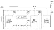
도 1에 도시된 것처럼, 본 발명의 일 실시예에 따른 캡슐 내시경용 체내 적응형 안테나 시스템은 인체 내에서 이미지 정보를 획득하는 이미지 센서(100), 상기 이미지 센서(100)에 의해서 획득되는 이미지 정보를 전달받아 처리하는 마이크로 프로세서(200) 및 알에프 수신부(320)를 통하여 전달되는 수신 알에프 신호를 상기 마이크로 프로세서(200)로 전송하고, 상기 마이크로 프로세서(200)가 처리하는 이미지 정보를 알에프 송수부를 통해서 송신하는 알에프 제어부(310)와, 상기 알에프 수신부(320)로 상기 수신 알에프 신호를 전달하고, 상기 알에프 송신부(330)로부터 전달되는 이미지 정보를 송신하며, 상기 인덕터(L1, L2)와 커패시턴스 크기가 가변되는 가변 커패시터부(C1, C2, C3, C4, S1, S2, S3, S4)로 구성되는 공진 회로부(340)를 포함하는 알에프 트랜시버(300)로 구성될 수 있다.As shown in FIG. 1 , the in vivo adaptive antenna system for a capsule endoscope according to an embodiment of the present invention includes an
여기에서, 상기 가변 커패시터부(C1, C2, C3, C4, S1, S2, S3, S4)는 다수의 커패시터가 병렬로 연결되고, 상기 다수의 커패시터(C1, C2, C3, C4) 각각에 턴온 및 턴오프를 조절하는 스위치(S1, S2, S3, S4)가 연결되어 커패시턴스 크기를 가변시킴으로써, 공진 회로부(340)의 공진 주파수를 조절할 수 있다.Here, in the variable capacitor units C1, C2, C3, C4, S1, S2, S3, and S4, a plurality of capacitors are connected in parallel, and the plurality of capacitors C1, C2, C3, and C4 are turned on, respectively. and switches S1 , S2 , S3 , and S4 for controlling turn-off are connected to vary the capacitance, so that the resonance frequency of the
구체적으로, 상기 가변 커패시터부(C1, C2, C3, C4, S1, S2, S3, S4)의 다수의 커패시터(C1, C2, C3, C4)는 높은 Q-factor를 갖는 커패시터인 MEMS(Micro-Electro Mechanical System) 커패시터로 구성될 수 있다.Specifically, the plurality of capacitors C1, C2, C3, and C4 of the variable capacitor units C1, C2, C3, C4, S1, S2, S3, and S4 is a micro-capacitor (MEMS) having a high Q-factor. Electro Mechanical System) capacitors.
한편, 상기 가변 커패시터부(C1, C2, C3, C4, S1, S2, S3, S4)는, 도 2에 도시된 것처럼, 제 1 커패시터(C1)와 상기 제 1 커패시터(C1)의 턴온 및 턴오프를 조절하는 제 1 스위치(S1)와, 상기 제 1 커패시터(C1)에 병렬 연결되는 제 2 커패시터(C2)와 상기 제 2 커패시터(C2)의 턴온 및 턴오프를 조절하는 제 2 스위치(S2)와, 상기 제 2 커패시터(C2)에 병렬 연결되는 제 3 커패시터(C3)와 상기 제 3 커패시터(C3)의 턴온 및 턴오프를 조절하는 제 3 스위치(S3)와, 상기 제 3 커패시터(C3)에 병렬 연결되는 제 4 커패시터(C4)와 상기 제 4 커패시터(C4)의 턴온 및 턴오프를 조절하는 제 4 스위치(S4)를 포함하며, 상기 제 2 커패시터(C2)의 커패시턴스 크기는 상기 제 1 커패시터(C1)의 커패시턴스 크기의 2 배이고, 상기 제 3 커패시터(C3)의 커패시턴스 크기는 상기 제 2 커패시터(C2)의 커패시턴스 크기의 2 배이며, 상기 제 4 커패시터(C4)의 커패시턴스 크기는 상기 제 3 커패시터(C3)의 커패시턴스 크기의 2 배이다.Meanwhile, in the variable capacitor units C1, C2, C3, C4, S1, S2, S3, and S4, as shown in FIG. 2 , the first capacitor C1 and the first capacitor C1 are turned on and turned on. A first switch S1 for controlling off, a second capacitor C2 connected in parallel to the first capacitor C1, and a second switch S2 for controlling turn-on and turn-off of the second capacitor C2 ), a third capacitor C3 connected in parallel to the second capacitor C2 and a third switch S3 for controlling turn-on and turn-off of the third capacitor C3, and the third capacitor C3 ) and a fourth capacitor C4 connected in parallel to the fourth capacitor C4 and a fourth switch S4 for controlling turn-on and turn-off of the fourth capacitor C4, wherein the capacitance of the second capacitor C2 is the first the capacitance of the first capacitor C1 is twice the capacitance of the third capacitor C3, the capacitance of the third capacitor C3 is twice the capacitance of the second capacitor C2, and the capacitance of the fourth capacitor C4 is It is twice the capacitance of the third capacitor C3.
예를 들면, 제 1 커패시터(C1)는 1 pF 커패시터로 구성되고, 제 2 커패시터(C2)는 2 pF 커패시터로 구성되며, 제 3 커패시터(C3)는 4 pF 커패시터로 구성되고, 제 4 커패시터(C4)는 8 pF 커패시터로 구성된다고 가정해보자.For example, the first capacitor C1 is composed of a 1 pF capacitor, the second capacitor C2 is composed of a 2 pF capacitor, the third capacitor C3 is composed of a 4 pF capacitor, and the fourth capacitor ( Assume that C4) consists of an 8 pF capacitor.
제 1 스위치(S1)만 턴온되는 경우에는 가변 커패시터부(C1, C2, C3, C4, S1, S2, S3, S4)의 커패시턴스는 1 pF이 되고, 제 2 스위치(S2)만 턴온되는 경우에는 가변 커패시터부(C1, C2, C3, C4, S1, S2, S3, S4)의 커패시턴스는 2 pF이 되며, 제 1 스위치(S1) 및 제 2 스위치(S2)만 턴온되는 경우에는 가변 커패시터부(C1, C2, C3, C4, S1, S2, S3, S4)의 커패시턴스는 3 pF이 되고, 제 3 스위치(S3)만 턴온되는 경우에는 가변 커패시터부(C1, C2, C3, C4, S1, S2, S3, S4)의 커패시턴스는 4 pF이 되며, 제 1 스위치(S1) 및 제 3 스위치(S3)만 턴온되는 경우에는 가변 커패시터부(C1, C2, C3, C4, S1, S2, S3, S4)의 커패시턴스는 5 pF이 되고, 제 2 스위치(S2) 및 제 3 스위치(S3)만 턴온되는 경우에는 가변 커패시터부(C1, C2, C3, C4, S1, S2, S3, S4)의 커패시턴스는 6 pF이 되며, 제 1 스위치(S1), 제 2 스위치(S2) 및 제 3 스위치(S3)만 턴온되는 경우에는 가변 커패시터부(C1, C2, C3, C4, S1, S2, S3, S4)의 커패시턴스는 7 pF이 되고, 제 4 스위치(S4)만 턴온되는 경우에는 가변 커패시터부(C1, C2, C3, C4, S1, S2, S3, S4)의 커패시턴스는 8 pF이 되며, 제 1 스위치(S1) 및 제 4 스위치(S4)만 턴온되는 경우에는 가변 커패시터부(C1, C2, C3, C4, S1, S2, S3, S4)의 커패시턴스는 9 pF이 되고, 제 2 스위치(S2) 및 제 4 스위치(S4)만 턴온되는 경우에는 가변 커패시터부(C1, C2, C3, C4, S1, S2, S3, S4)의 커패시턴스는 10 pF이 되며, 제 1 스위치(S1), 제 2 스위치(S2) 및 제 3 스위치(S3)만 턴온되는 경우에는 가변 커패시터부(C1, C2, C3, C4, S1, S2, S3, S4)의 커패시턴스는 11 pF이 되고, 제 3 스위치(S3) 및 제 4 스위치(S4)만 턴온되는 경우에는 가변 커패시터부(C1, C2, C3, C4, S1, S2, S3, S4)의 커패시턴스는 12 pF이 되며, 제 1 스위치(S1), 제 3 스위치(S3) 및 제 4 스위치(S4)만 턴온되는 경우에는 가변 커패시터부(C1, C2, C3, C4, S1, S2, S3, S4)의 커패시턴스는 13 pF이 되고, 제 2 스위치(S2), 제 3 스위치(S3) 및 제 4 스위치(S4)만 턴온되는 경우에는 가변 커패시터부(C1, C2, C3, C4, S1, S2, S3, S4)의 커패시턴스는 14 pF이 되며, 제 1 스위치(S1), 제 2 스위치(S2), 제 3 스위치(S3) 및 제 4 스위치(S4) 모두가 턴온되는 경우에는 가변 커패시터부(C1, C2, C3, C4, S1, S2, S3, S4)의 커패시턴스는 15 pF이 된다.When only the first switch S1 is turned on, the capacitance of the variable capacitor units C1, C2, C3, C4, S1, S2, S3, S4 becomes 1 pF, and when only the second switch S2 is turned on The capacitance of the variable capacitor units C1, C2, C3, C4, S1, S2, S3, and S4 is 2 pF, and when only the first switch S1 and the second switch S2 are turned on, the variable capacitor unit ( The capacitance of C1, C2, C3, C4, S1, S2, S3, and S4 becomes 3 pF, and when only the third switch S3 is turned on, the variable capacitor units C1, C2, C3, C4, S1, S2 , S3 and S4 have a capacitance of 4 pF, and when only the first switch S1 and the third switch S3 are turned on, the variable capacitor units C1, C2, C3, C4, S1, S2, S3, S4 ) becomes 5 pF, and when only the second switch S2 and the third switch S3 are turned on, the capacitance of the variable capacitor units C1, C2, C3, C4, S1, S2, S3, S4 is 6 pF, and when only the first switch S1, the second switch S2, and the third switch S3 are turned on, the variable capacitor units C1, C2, C3, C4, S1, S2, S3, S4 is 7 pF, and when only the fourth switch S4 is turned on, the capacitance of the variable capacitor units C1, C2, C3, C4, S1, S2, S3, S4 is 8 pF, and the first switch When only (S1) and the fourth switch (S4) are turned on, the capacitance of the variable capacitor units (C1, C2, C3, C4, S1, S2, S3, S4) is 9 pF, and the second switch (S2) and When only the fourth switch S4 is turned on, the capacitance of the variable capacitor units C1, C2, C3, C4, S1, S2, S3, and S4 is 10 pF, and the first switch S1, the second switch S S2) and when only the third switch S3 is turned on, the variable capacitor units C1, C2, C3, C4, S1, S2, The capacitances of S3 and S4 are 11 pF, and when only the third switch S3 and the fourth switch S4 are turned on, the variable capacitor units C1, C2, C3, C4, S1, S2, S3, and S4 are turned on. is 12 pF, and when only the first switch S1, the third switch S3 and the fourth switch S4 are turned on, the variable capacitor units C1, C2, C3, C4, S1, S2, S3 , S4 has a capacitance of 13 pF, and when only the second switch S2, the third switch S3, and the fourth switch S4 are turned on, the variable capacitor units C1, C2, C3, C4, S1, The capacitance of S2, S3, and S4 becomes 14 pF, and when all of the first switch S1, the second switch S2, the third switch S3, and the fourth switch S4 are turned on, the variable capacitor unit The capacitance of (C1, C2, C3, C4, S1, S2, S3, S4) becomes 15 pF.
즉, 제 1 스위치(S1), 제 2 스위치(S2), 제 3 스위치(S3) 및 제 4 스위치(S4)의 턴온 및 턴오프를 제어함으로써, 가변 커패시터부(C1, C2, C3, C4, S1, S2, S3, S4)의 커패시턴스는 1 pF ~ 15 pF까지 15가지로 조절될 수 있다.That is, by controlling the turn-on and turn-off of the first switch S1, the second switch S2, the third switch S3, and the fourth switch S4, the variable capacitor units C1, C2, C3, C4, The capacitance of S1, S2, S3, S4) can be adjusted in 15 ways, ranging from 1 pF to 15 pF.
이러한 가변 커패시터부(C1, C2, C3, C4, S1, S2, S3, S4)는 반드시 제 1 커패시터(C1), 제 2 커패시터(C2), 제 3 커패시터(C3), 제 4 커패시터(C4), 제 1 스위치(S1), 제 2 스위치(S2), 제 3 스위치(S3) 및 제 4 스위치(S4)로 구성될 필요는 없으며, 필요에 따라서 제 1 커패시터(C1), 제 2 커패시터(C2), 제 3 커패시터(C3), 제 1 스위치(S1), 제 2 스위치(S2) 및 제 3 스위치(S3)로 구성될 수도 있다.The variable capacitor units C1, C2, C3, C4, S1, S2, S3, and S4 are necessarily the first capacitor C1, the second capacitor C2, the third capacitor C3, and the fourth capacitor C4. , the first switch S1 , the second switch S2 , the third switch S3 and the fourth switch S4 do not have to be configured, and the first capacitor C1 and the second capacitor C2 are required as needed. ), a third capacitor C3, a first switch S1, a second switch S2, and a third switch S3.
가변 커패시터부(C1, C2, C3, C4, S1, S2, S3, S4)가 제 1 커패시터(C1), 제 2 커패시터(C2), 제 3 커패시터(C3), 제 1 스위치(S1), 제 2 스위치(S2) 및 제 3 스위치(S3)로 구성되는 경우에는 7 가지의 커패시턴스로 조절될 수 있고, 가변 커패시터부(C1, C2, C3, C4, S1, S2, S3, S4)가 제 1 커패시터(C1), 제 2 커패시터(C2), 제 3 커패시터(C3), 제 4 커패시터(C4), 제 5 커패시터, 제 1 스위치(S1), 제 2 스위치(S2), 제 3 스위치(S3), 제 4 스위치(S4) 및 제 5 스위치로 구성되는 경우에는 31 가지의 커패시턴스로 조절될 수 있으며, 가변 커패시터부(C1, C2, C3, C4, S1, S2, S3, S4)가 제 1 커패시터(C1), 제 2 커패시터(C2), 제 3 커패시터(C3), 제 4 커패시터(C4), 제 5 커패시터, 제 6 커패시터, 제 1 스위치(S1), 제 2 스위치(S2), 제 3 스위치(S3), 제 4 스위치(S4), 제 5 스위치 및 제 6 스위치로 구성되는 경우에는 63 가지의 커패시턴스로 조절될 수 있다.The variable capacitor units C1, C2, C3, C4, S1, S2, S3, and S4 include the first capacitor C1, the second capacitor C2, the third capacitor C3, the first switch S1, and the first capacitor C1. When the second switch S2 and the third switch S3 are configured, the seven capacitances can be adjusted, and the variable capacitor units C1, C2, C3, C4, S1, S2, S3, and S4 include the first Capacitor C1, second capacitor C2, third capacitor C3, fourth capacitor C4, fifth capacitor, first switch S1, second switch S2, third switch S3 , the fourth switch (S4) and the fifth switch can be adjusted to 31 kinds of capacitance, and the variable capacitor units (C1, C2, C3, C4, S1, S2, S3, S4) is the first capacitor (C1), second capacitor (C2), third capacitor (C3), fourth capacitor (C4), fifth capacitor, sixth capacitor, first switch (S1), second switch (S2), third switch In the case of (S3), the fourth switch (S4), the fifth switch, and the sixth switch, 63 kinds of capacitance can be adjusted.
여기에서, 본 발명의 일 실시예에 따른 캡슐 내시경용 체내 적응형 안테나 시스템은 상기 가변 커패시터부(C1, C2, C3, C4, S1, S2, S3, S4)의 커패시턴스 크기가 인체 내에서 캡슐 내시경의 위치 정보에 따른 해당 유전율 크기에 따라서 조절될 수 있다.Here, in the in vivo adaptive antenna system for a capsule endoscope according to an embodiment of the present invention, the capacitance of the variable capacitor units C1, C2, C3, C4, S1, S2, S3, S4 is the capsule endoscope in the human body. It can be adjusted according to the magnitude of the dielectric constant according to the position information of the .
구체적으로, 캡슐 내시경의 주변 유전율 크기에 따른 공진 회로부(340)의 커패시턴스를 마이크로 프로세서(200)의 룩업 테이블에 저장하고, 캡슐 내시경을 트랙킹하여 캡슐 내시경의 인체 내에서의 위치 정보를 파악한 후에, 해당 유전율 크기에 따라서 가변 커패시턴스 크기를 조절할 수 있다.Specifically, the capacitance of the
한편, 본 발명의 일 실시예에 따른 캡슐 내시경용 체내 적응형 안테나 시스템은 상기 가변 커패시터부(C1, C2, C3, C4, S1, S2, S3, S4)의 커패시턴스 크기가 상기 공진 회로부(340)를 통해서 송신되는 알에프 신호의 SNR(Signal to Noise Ratio)의 최대가 되는 상기 제 1 스위치(S1), 상기 제 2 스위치(S2), 상기 제 3 스위치(S3) 및 상기 제 4 스위치(S4)의 턴온 및 턴오프 조합을 스캔하여 조절될 수 있다.On the other hand, in the in vivo adaptive antenna system for a capsule endoscope according to an embodiment of the present invention, the capacitance of the variable capacitor units C1, C2, C3, C4, S1, S2, S3, S4 is the
구체적으로, 상기 제 1 스위치(S1), 상기 제 2 스위치(S2), 상기 제 3 스위치(S3) 및 상기 제 4 스위치(S4)의 턴온 및 턴오프의 15가지 조합으로 결정되는 가변 커패시터부(C1, C2, C3, C4, S1, S2, S3, S4)의 커패시턴스를 변경하여 상기 공진 회로부(340)를 통해서 송신되는 알에프 신호의 SNR(Signal to Noise Ratio)의 최대가 되는 가변 커패시터부(C1, C2, C3, C4, S1, S2, S3, S4)의 커패시턴스로 조절할 수 있다.Specifically, a variable capacitor unit determined by 15 combinations of turn-on and turn-off of the first switch S1, the second switch S2, the third switch S3, and the fourth switch S4 ( The variable capacitor unit C1 that maximizes the Signal to Noise Ratio (SNR) of the RF signal transmitted through the
이상, 본 발명을 본 발명의 원리를 예시하기 위한 바람직한 실시예와 관련하여 설명하고 도시하였지만, 본 발명은 그와 같이 도시되고 설명된 그대로의 구성 및 작용으로 한정되는 것이 아니다.While the present invention has been described and illustrated in connection with preferred embodiments for illustrating the principles of the present invention, the present invention is not limited to the construction and operation as so shown and described.
오히려, 첨부된 청구범위의 사상 및 범주를 일탈함이 없이 본 발명에 대한 다수의 변경 및 수정이 가능함을 당업자들은 잘 이해할 수 있을 것이다.Rather, it will be apparent to those skilled in the art that many changes and modifications can be made to the present invention without departing from the spirit and scope of the appended claims.
따라서, 그러한 모든 적절한 변경 및 수정과 균등물들도 본 발명의 범위에 속하는 것으로 간주되어야 할 것이다.Accordingly, all such suitable alterations and modifications and equivalents are to be considered as falling within the scope of the present invention.
100 : 이미지 센서
200 : 마이크로 프로세서
300 : 알에프 트랜시버
310 : 알에프 제어부
320 : 알에프 수신부
330 : 알에프 송신부
340 : 공진 회로부
L1, L2 : 인덕터
C1, C2, C3, C4, S1, S2, S3, S4 : 가변 커패시터부
S1, S2, S3, S4 : 스위치100: image sensor
200: microprocessor
300: RF transceiver
310: RF control unit
320: RF receiver
330: RF transmitter
340: resonance circuit unit
L1, L2 : Inductor
C1, C2, C3, C4, S1, S2, S3, S4: variable capacitor part
S1, S2, S3, S4: switch
Claims (5)
Translated fromKorean상기 이미지 센서에 의해서 획득되는 이미지 정보를 전달받아 처리하는 마이크로 프로세서; 및
알에프 수신부를 통하여 전달되는 수신 알에프 신호를 상기 마이크로 프로세서로 전송하고, 상기 마이크로 프로세서가 처리하는 이미지 정보를 알에프 송신부를 통해서 송신하는 알에프 제어부와, 상기 알에프 수신부로 상기 수신 알에프 신호를 전달하고, 상기 알에프 송신부로부터 전달되는 이미지 정보를 송신하며, 인덕터와 커패시턴스 크기가 가변되는 가변 커패시터부로 구성되는 공진 회로부를 포함하는 알에프 트랜시버;를 포함하며,
상기 가변 커패시터부는 다수의 커패시터가 병렬로 연결되고, 상기 다수의 커패시터 각각에 턴온 및 턴오프를 조절하는 스위치가 연결되어 커패시턴스 크기를 가변시킴으로써, 공진 주파수를 조절하고,
상기 가변 커패시터부의 다수의 커패시터는 MEMS(Micro-Electro Mechanical System) 커패시터로 구성되며,
상기 가변 커패시터부는 제 1 커패시터와 상기 제 1 커패시터의 턴온 및 턴오프를 조절하는 제 1 스위치와, 상기 제 1 커패시터에 병렬 연결되는 제 2 커패시터와 상기 제 2 커패시터의 턴온 및 턴오프를 조절하는 제 2 스위치와, 상기 제 2 커패시터에 병렬 연결되는 제 3 커패시터와 상기 제 3 커패시터의 턴온 및 턴오프를 조절하는 제 3 스위치와, 상기 제 3 커패시터에 병렬 연결되는 제 4 커패시터와 상기 제 4 커패시터의 턴온 및 턴오프를 조절하는 제 4 스위치를 포함하며,
상기 제 2 커패시터의 커패시턴스 크기는 상기 제 1 커패시터의 커패시턴스 크기의 2 배이고, 상기 제 3 커패시터의 커패시턴스 크기는 상기 제 2 커패시터의 커패시턴스 크기의 2 배이며, 상기 제 4 커패시터의 커패시턴스 크기는 상기 제 3 커패시터의 커패시턴스 크기의 2 배이고,
상기 가변 커패시터부의 커패시턴스 크기는 캡슐 내시경을 트랙킹하여 상기 캡슐 내시경의 인체 내에서의 위치 정보를 파악하여, 상기 캡슐 내시경의 위치 정보에 따른 해당 유전율 크기에 따라서 조절되는 것을 특징으로 하는 캡슐 내시경용 체내 적응형 안테나 시스템.
an image sensor for acquiring image information in the human body;
a microprocessor for receiving and processing image information obtained by the image sensor; and
an RF control unit for transmitting the received RF signal transmitted through the RF receiving unit to the microprocessor and transmitting image information processed by the microprocessor through the RF transmitting unit; An RF transceiver that transmits the image information transmitted from the transmitter and includes a resonance circuit part composed of an inductor and a variable capacitor part having a variable capacitance.
In the variable capacitor unit, a plurality of capacitors are connected in parallel, and a switch for controlling turn-on and turn-off is connected to each of the plurality of capacitors to vary the capacitance, thereby adjusting the resonance frequency;
A plurality of capacitors of the variable capacitor unit are configured as MEMS (Micro-Electro Mechanical System) capacitors,
The variable capacitor unit includes a first capacitor and a first switch for controlling turn-on and turn-off of the first capacitor, and a second capacitor connected in parallel to the first capacitor and a second capacitor for controlling turn-on and turn-off of the second capacitor. a second switch, a third capacitor connected in parallel to the second capacitor, a third switch controlling turn-on and turn-off of the third capacitor, and a fourth capacitor and the fourth capacitor connected in parallel to the third capacitor a fourth switch for regulating turn-on and turn-off;
The capacitance magnitude of the second capacitor is twice the capacitance magnitude of the first capacitor, the capacitance magnitude of the third capacitor is twice the capacitance magnitude of the second capacitor, and the capacitance magnitude of the fourth capacitor is the third capacitor. twice the capacitance of the capacitor,
Capacitance size of the variable capacitor part is adjusted according to the size of the dielectric constant according to the position information of the capsule endoscope by tracking the capsule endoscope to grasp the position information of the capsule endoscope in the human body. type antenna system.
Priority Applications (1)
| Application Number | Priority Date | Filing Date | Title |
|---|---|---|---|
| KR1020190156806AKR102275776B1 (en) | 2019-11-29 | 2019-11-29 | In vivo adaptive antenna system for capsule endoscope |
Applications Claiming Priority (1)
| Application Number | Priority Date | Filing Date | Title |
|---|---|---|---|
| KR1020190156806AKR102275776B1 (en) | 2019-11-29 | 2019-11-29 | In vivo adaptive antenna system for capsule endoscope |
Publications (2)
| Publication Number | Publication Date |
|---|---|
| KR20210067324A KR20210067324A (en) | 2021-06-08 |
| KR102275776B1true KR102275776B1 (en) | 2021-07-13 |
Family
ID=76399828
Family Applications (1)
| Application Number | Title | Priority Date | Filing Date |
|---|---|---|---|
| KR1020190156806AActiveKR102275776B1 (en) | 2019-11-29 | 2019-11-29 | In vivo adaptive antenna system for capsule endoscope |
Country Status (1)
| Country | Link |
|---|---|
| KR (1) | KR102275776B1 (en) |
Families Citing this family (1)
| Publication number | Priority date | Publication date | Assignee | Title |
|---|---|---|---|---|
| US20230139164A1 (en)* | 2021-11-04 | 2023-05-04 | AyDeeKay LLC dba Indie Semiconductor | Single-FET Mux Switch for Coil Selection |
Family Cites Families (5)
| Publication number | Priority date | Publication date | Assignee | Title |
|---|---|---|---|---|
| US8102266B2 (en)* | 2005-01-21 | 2012-01-24 | Olympus Corporation | Radio intra-subject information acquiring system |
| JP5086618B2 (en)* | 2006-11-27 | 2012-11-28 | オリンパス株式会社 | Capsule endoscope |
| KR101087909B1 (en)* | 2007-10-01 | 2011-11-30 | 올림푸스 가부시키가이샤 | Capsule-type medical devices and capsule-type medical systems |
| KR101674580B1 (en)* | 2010-03-26 | 2016-11-09 | 삼성전자주식회사 | Apparatus and method for measuring biological signal |
| KR101811292B1 (en)* | 2011-07-06 | 2017-12-26 | 엘지전자 주식회사 | Wireless power transmitter and wireless power receiver having fuction of resonance frequency control |
- 2019
- 2019-11-29KRKR1020190156806Apatent/KR102275776B1/enactiveActive
Also Published As
| Publication number | Publication date |
|---|---|
| KR20210067324A (en) | 2021-06-08 |
Similar Documents
| Publication | Publication Date | Title |
|---|---|---|
| EP2328233B1 (en) | Antenna and radio communication apparatus | |
| EP3651270B1 (en) | Electronic device | |
| EP2751928B1 (en) | Antenna tuning on an impedance trajectory | |
| CN105490026B (en) | A kind of electronic equipment and information processing method | |
| TWI309108B (en) | Switchable dual-band filter | |
| EP2637552A1 (en) | Location based wireless medical device | |
| KR102275776B1 (en) | In vivo adaptive antenna system for capsule endoscope | |
| US8400234B2 (en) | Apparatus for removing leakage signal | |
| US20150172426A1 (en) | Antenna tuning correction for multiple rear housing materials | |
| US20170084989A1 (en) | System and Method for Adaptive Aperture Tunable Antenna | |
| JP2003032063A (en) | Antenna matching unit of mobile communication terminal | |
| JP2021503337A5 (en) | ||
| JP2014230276A (en) | Radio frequency matching circuit and wireless communication device | |
| TWI659628B (en) | Wireless communication device | |
| CN104038176A (en) | Wearable device and antenna self-adaption impedance matching system thereof | |
| KR101021495B1 (en) | Wireless communication device and wireless communication method | |
| US9900038B2 (en) | Communication device | |
| CN104269605A (en) | Electronic device | |
| CN108206331A (en) | Antenna assembly and its mobile terminal | |
| JP2007089892A (en) | Apparatus introduced into subject, apparatus used outside of subject, and system introduced into subject | |
| WO2008010027A1 (en) | Transmitting device and method of tuning the transmitting device | |
| WO2008053443A1 (en) | Implantable device with remote readout | |
| TWI553958B (en) | Wireless communication device | |
| CN113595579B (en) | Radio frequency switch module and radio frequency switch circuit | |
| JP4897114B2 (en) | Transmission device, in-subject introduction device, and transmission / reception system |
Legal Events
| Date | Code | Title | Description |
|---|---|---|---|
| PA0109 | Patent application | Patent event code:PA01091R01D Comment text:Patent Application Patent event date:20191129 | |
| PA0201 | Request for examination | ||
| PE0902 | Notice of grounds for rejection | Comment text:Notification of reason for refusal Patent event date:20201027 Patent event code:PE09021S01D | |
| PE0701 | Decision of registration | Patent event code:PE07011S01D Comment text:Decision to Grant Registration Patent event date:20210406 | |
| PG1501 | Laying open of application | ||
| GRNT | Written decision to grant | ||
| PR0701 | Registration of establishment | Comment text:Registration of Establishment Patent event date:20210705 Patent event code:PR07011E01D | |
| PR1002 | Payment of registration fee | Payment date:20210706 End annual number:3 Start annual number:1 | |
| PG1601 | Publication of registration | ||
| PR1001 | Payment of annual fee | Payment date:20240704 Start annual number:4 End annual number:4 | |
| PR1001 | Payment of annual fee | Payment date:20250623 Start annual number:5 End annual number:5 |