KR102272563B1 - Emergency releasing device of rechargeable door for automobile - Google Patents
Emergency releasing device of rechargeable door for automobileDownload PDFInfo
- Publication number
- KR102272563B1 KR102272563B1KR1020190040836AKR20190040836AKR102272563B1KR 102272563 B1KR102272563 B1KR 102272563B1KR 1020190040836 AKR1020190040836 AKR 1020190040836AKR 20190040836 AKR20190040836 AKR 20190040836AKR 102272563 B1KR102272563 B1KR 102272563B1
- Authority
- KR
- South Korea
- Prior art keywords
- release
- emergency release
- emergency
- charging door
- rotary lever
- Prior art date
- Legal status (The legal status is an assumption and is not a legal conclusion. Google has not performed a legal analysis and makes no representation as to the accuracy of the status listed.)
- Active
Links
- 238000000926separation methodMethods0.000claimsdescription3
- 230000000149penetrating effectEffects0.000claimsdescription2
- 238000000034methodMethods0.000claims5
- 238000006073displacement reactionMethods0.000description5
- 230000008878couplingEffects0.000description4
- 238000010168coupling processMethods0.000description4
- 238000005859coupling reactionMethods0.000description4
- 230000001419dependent effectEffects0.000description3
- 230000000694effectsEffects0.000description3
- 238000009434installationMethods0.000description3
- 230000004308accommodationEffects0.000description1
- 238000005452bendingMethods0.000description1
- 238000004519manufacturing processMethods0.000description1
- 238000012986modificationMethods0.000description1
- 230000004048modificationEffects0.000description1
Images


Classifications
- E—FIXED CONSTRUCTIONS
- E05—LOCKS; KEYS; WINDOW OR DOOR FITTINGS; SAFES
- E05B—LOCKS; ACCESSORIES THEREFOR; HANDCUFFS
- E05B83/00—Vehicle locks specially adapted for particular types of wing or vehicle
- E05B83/28—Locks for glove compartments, console boxes, fuel inlet covers or the like
- E—FIXED CONSTRUCTIONS
- E05—LOCKS; KEYS; WINDOW OR DOOR FITTINGS; SAFES
- E05B—LOCKS; ACCESSORIES THEREFOR; HANDCUFFS
- E05B77/00—Vehicle locks characterised by special functions or purposes
- E05B77/02—Vehicle locks characterised by special functions or purposes for accident situations
- E—FIXED CONSTRUCTIONS
- E05—LOCKS; KEYS; WINDOW OR DOOR FITTINGS; SAFES
- E05B—LOCKS; ACCESSORIES THEREFOR; HANDCUFFS
- E05B79/00—Mounting or connecting vehicle locks or parts thereof
- E05B79/10—Connections between movable lock parts
- E05B79/20—Connections between movable lock parts using flexible connections, e.g. Bowden cables
- E—FIXED CONSTRUCTIONS
- E05—LOCKS; KEYS; WINDOW OR DOOR FITTINGS; SAFES
- E05B—LOCKS; ACCESSORIES THEREFOR; HANDCUFFS
- E05B79/00—Mounting or connecting vehicle locks or parts thereof
- E05B79/10—Connections between movable lock parts
- E05B79/22—Operative connections between handles, sill buttons or lock knobs and the lock unit
Landscapes
- Lock And Its Accessories (AREA)
- Electric Propulsion And Braking For Vehicles (AREA)
Abstract
Translated fromKorean
Description
Translated fromKorean본 발명은 자동차의 충전용 도어의 개폐장치에 적용되는 비상해제 장치에 관한 것으로, 더욱 상세하게는 록킹기구의 회전레버와 비상해제용 릴리스기구의 손잡이 사이를 연결하는 비상해제용 케이블의 작동길이에 대한 최적화 설계를 통해 충전용 도어의 잠금 해제시 간섭부 검토 및 기능성 검토에 유리하고, 비상해제 작동시 릴리스기구의 작동상태를 육안으로 인지 가능하게 하여 충전용 도어에 대한 개폐상태를 보다 용이하게 판단할 수 있는 자동차의 충전용 도어의 비상해제 장치에 관한 것이다.The present invention relates to an emergency release device applied to an opening and closing device for a charging door of a vehicle, and more particularly, to the operating length of an emergency release cable connecting between a rotary lever of a locking mechanism and a handle of an emergency release release mechanism. It is advantageous for review of interference parts and functional review when unlocking the charging door through an optimized design for the charging door, and it makes it easier to judge the open/closed state of the charging door by making it possible to visually recognize the operating state of the release mechanism during emergency release operation. It relates to an emergency release device for a charging door of a vehicle that can do this.
일반적으로 전기 자동차는 배터리와 모터를 구비하고서 배터리에 축적된 전기 에너지를 이용하여 모터를 회전시킴으로써 주행에 필요로 하는 구동력을 얻도록 구성된다.In general, an electric vehicle is provided with a battery and a motor, and is configured to obtain a driving force required for driving by rotating the motor using electric energy stored in the battery.
이에 따라, 전기 자동차는 등록특허 제10-1575498호에 개시된 바와 같이 차체에 대해 개폐 가능하게 설치되는 충전용 도어를 구비하고, 충전용 도어를 매개로 개방되는 부위에는 플러그와의 결합 가능한 충전용 커넥터를 구비하고 있다. 또한, 전기 자동차는 충전용 도어에 대한 개폐를 잠금상태 또는 잠금 해제상태로 전환하는 별도의 록킹기구를 구비하고 있다.Accordingly, as disclosed in Korean Patent Registration No. 10-1575498, the electric vehicle has a charging door that is installed to be openable and openable with respect to the vehicle body, and a charging connector that can be coupled with a plug at a portion opened through the charging door as a medium. is provided In addition, the electric vehicle is provided with a separate locking mechanism for switching the opening and closing of the charging door to the locked state or the unlocked state.
이 경우, 충전용 도어는 록킹기구에 의한 잠금해제가 원활하게 이루어지지 않을 경우를 대비하여 비상용 해제장치를 구비하는 데, 종래 비상용 해제장치는 등록특허 제10-1799285호에서와 같이 액츄에이터의 잠금상태를 릴리스케이블에 대한 수동 조작을 통해 강제적으로 해제시킬 수 있도록 구성된다.In this case, the charging door is provided with an emergency release device in case the lock is not smoothly released by the locking mechanism, and the conventional emergency release device locks the actuator as in Patent Registration No. 10-1799285. It is configured so that it can be forcibly released through manual operation of the release cable.
이를 위해, 록킹기구와 비상용 해제장치 사이에는 릴리스케이블을 이용한 물리적 연결구조를 가지게 되는 데, 종래 비상용 해제장치에서 릴리스케이블의 설치길이는 액츄에이터의 잠금상태를 기준으로 설정되기 때문에 충전용 도어의 개폐시 잠금해제 위치에 따른 케이블의 간섭과 기능성에 대한 검토가 곤란한 단점이 있었다.To this end, there is a physical connection structure using a release cable between the locking mechanism and the emergency release device. Since the installation length of the release cable in the conventional emergency release device is set based on the locking state of the actuator, when the charging door is opened and closed There was a disadvantage in that it was difficult to review the cable interference and functionality according to the unlocking position.
본 발명이 해결하고자 하는 기술적 과제는 록킹기구의 회전레버와 비상해제용 릴리스기구의 손잡이 사이를 연결하는 비상해제용 케이블에 대한 작동길이의 최적화 설계를 통해 충전용 도어의 잠금 해제시 간섭부 검토 및 기능성 검토에 유리함과 더불어, 비상해제 작동시 릴리스기구의 손잡이 작동상태를 육안으로 인지 가능하게 하여 충전용 도어에 대한 개폐상태를 보다 용이하게 판단할 수 있는 자동차의 충전용 도어의 비상해제 장치를 제공하는 것이다.The technical problem to be solved by the present invention is to review the interference part when unlocking the charging door through the optimized design of the operating length for the emergency release cable connecting between the rotary lever of the locking mechanism and the handle of the emergency release release mechanism. In addition to being advantageous for functional review, it is possible to visually recognize the operating state of the handle of the release mechanism during the emergency release operation, thereby providing an emergency release device for the charging door of the vehicle that can more easily determine the open/closed state of the charging door. will do
상기와 같은 기술적 과제를 해결하기 위한 본 발명은 선회 가능한 회전레버를 갖추고서 충전용 도어의 잠금상태를 조절하도록 설치되는 록킹기구, 상기 록킹기구에 대한 비상시 강제 해제를 위해 상기 회전레버와 연동 가능하게 설치되는 릴리스기구, 및 상기 록킹기구의 회전레버와 상기 릴리스기구 사이를 연결하는 비상해제용 케이블을 구비하고, 상기 비상해제용 케이블은 상기 회전레버의 해제상태를 기준으로 상기 릴리스기구와 연동 가능한 구조로 연결되도록 구성되는 것이 바람직하다.The present invention for solving the above technical problems is a locking mechanism that is equipped with a pivotable rotary lever and is installed to adjust the locking state of the charging door, to be interlocked with the rotary lever to forcibly release the locking mechanism in an emergency a release mechanism installed, and an emergency release cable connecting between the rotary lever of the locking mechanism and the release mechanism, wherein the emergency release cable is interlockable with the release mechanism based on the release state of the rotary lever It is preferable to be configured to be connected to
본 발명의 바람직한 실시예로서, 상기 릴리스기구는 차체측에 고정되는 하우징, 상기 하우징의 내부에 이동 가능하게 설치되는 손잡이, 상기 손잡이에 고정되고 상기 비상해제용 케이블의 자유단부와 결합되는 가동체, 상기 하우징에 고정되고 내부에 상기 비상해제용 케이블을 이동 가능하게 관통하여 수용하는 중공형 몸체, 및 상기 가동체와 상기 중공형 몸체 사이에 양단부가 고정되도록 설치되는 부트씨일을 구비하고, 상기 비상해제용 케이블은 일단부가 상기 회전레버에 연결되고 타단부가 상기 가동체에 연결되되, 상기 비상해제용 케이블의 작동길이는 상기 회전레버의 해제상태를 기준으로 상기 회전레버와 상기 가동체 사이를 타이트하게 연동 가능한 구조로 연결하도록 설정되도록 구성되는 것이 바람직하다.In a preferred embodiment of the present invention, the release mechanism includes a housing fixed to the vehicle body side, a handle movably installed inside the housing, a movable body fixed to the handle and coupled to a free end of the emergency release cable; A hollow body fixed to the housing and movably accommodating the emergency release cable therein, and a boot seal installed so that both ends are fixed between the movable body and the hollow body, One end of the cable for release is connected to the rotary lever and the other end is connected to the movable body, and the operating length of the emergency release cable is tight between the rotary lever and the movable body based on the release state of the rotary lever. It is preferable that it is configured to be set to be connected in an interlockable structure.
본 발명의 바람직한 실시예로서, 상기 가동체의 외주면에는 상기 부트씨일의 일단부가 체결용 클립을 매개로 스웨이징 처리되어 고정되도록 구성되고, 상기 가동체는 자유단부에 상기 부트씨일의 일단부에 대한 이탈 방지를 위해 반경방향 외측으로 돌출되는 외향 돌기부를 구비하도록 구성되는 것이 바람직하다.In a preferred embodiment of the present invention, one end of the boot seal is fixed to an outer circumferential surface of the movable body by swaging through a fastening clip, and the movable body has one end of the boot seal at the free end. It is preferable to be configured to have an outwardly protruding portion protruding outward in the radial direction in order to prevent separation with respect to the .
본 발명의 바람직한 실시예로서, 상기 중공형 몸체는 상기 부트씨일의 타단부를 외주면에 고정하기 위해 단차진 형태로서 반경방향으로 크기가 축소되는 요홈부를 구비하도록 구성되는 것이 바람직하다.In a preferred embodiment of the present invention, the hollow body is preferably configured to have a concave portion that is reduced in size in the radial direction in a stepped shape to fix the other end of the boot seal to the outer circumferential surface.
본 발명은 상기 가동체와 상기 중공형 몸체 사이에 설치되는 리턴 스프링을 더 포함하고, 상기 리턴 스프링은 상기 비상해제용 케이블을 내부에 관통하여 수용하도록 설치되는 것이 바람직하다.Preferably, the present invention further includes a return spring installed between the movable body and the hollow body, and the return spring is installed to receive the emergency release cable through the inside.
본 발명의 바람직한 실시예로서, 상기 손잡이는 상기 하우징의 내부에 이동 가능하게 배치되는 수용체, 및 상기 수용체로부터 반경방향 외측으로 돌출되는 파지부를 일체로 구비하고, 상기 하우징은 상기 파지부의 이동 스트로크에 대한 거리 제한을 위해 외부와 교통 가능하도록 길이방향을 따라 절개되는 슬롯부를 구비하는 것이 바람직하다.In a preferred embodiment of the present invention, the handle is integrally provided with a receptor movably disposed inside the housing, and a gripper projecting radially outwardly from the container, and the housing includes a movement stroke of the gripper. It is preferable to have a slot part cut along the longitudinal direction so as to be able to communicate with the outside in order to limit the distance to the .
본 발명의 실시예에 따른 자동차의 충전용 도어의 비상해제 장치는 록킹기구의 회전레버와 릴리스기구의 손잡이 사이를 연동 가능한 구조로 연결하는 비상해제용 케이블에 대한 길이 설정을 회전레버의 해제상태를 기준으로 이루어짐에 따라, 충전용 도어의 잠금과 해제 조작시 간섭부에 대한 검토 및 기능성에 대한 검토에 보다 유리한 효과를 제공한다.The emergency release device for the charging door of a vehicle according to an embodiment of the present invention sets the length of the emergency release cable connecting between the rotary lever of the locking mechanism and the handle of the release mechanism in an interlockable structure to determine the release state of the rotary lever. As it is made as a standard, it provides a more advantageous effect in the review of the interference part and the review of the functionality during the locking and unlocking operation of the charging door.
또한, 본 발명은 록킹기구에 대한 정상적인 해제 작동과 비상해제 작동시 비상해제용 케이블을 매개로 종속적인 변위를 수반하는 릴리스기구의 작동상태를 육안으로 인지 가능하게 하므로 충전용 도어에 대한 개폐상태를 보다 용이하게 판단할 수 있는 효과를 제공하게 된다.In addition, the present invention makes it possible to visually recognize the operating state of the release mechanism accompanying the dependent displacement via the emergency release cable during the normal release operation of the locking mechanism and the emergency release operation, so that the opening and closing state of the charging door is controlled. An effect that can be judged more easily is provided.
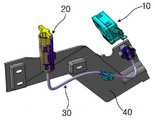
도 1은 본 발명의 실시예에 따른 충전용 도어의 비상해제 장치에 대한 차체측 설치상태를 개략적으로 도시한 사시도이다.
도 2는 본 발명의 실시예에 따른 충전용 도어의 비상해제 장치의 구성에 있어, 록킹기구와 릴리스기구 사이에 비상해제용 케이블이 설치된 상태를 도시한 사시도이다.
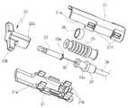
도 3은 도 2에 도시된 릴리스기구에 대한 주요 구성부위를 분해하여 도시한 사시도이다.
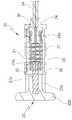
도 4는 도 2에 도시된 릴리스기구에 대한 주요 구성부위를 단면 처리하여 도시한 종단면도이다.
도 5는 도 1에 도시된 록킹기구와 릴리스기구의 잠금상태와 잠금 해제상태에 있어, 회전레버와 손잡이의 종속적인 연동 변위상태를 도시한 도면이다.1 is a perspective view schematically illustrating a vehicle body side installation state of an emergency release device for a charging door according to an embodiment of the present invention.
Figure 2 is a perspective view showing a state in which the emergency release cable is installed between the locking mechanism and the release mechanism in the configuration of the emergency release device for the charging door according to the embodiment of the present invention.
Figure 3 is an exploded perspective view showing the main components of the release mechanism shown in Figure 2;
FIG. 4 is a longitudinal cross-sectional view showing the main components of the release mechanism shown in FIG.
5 is a view showing the dependent interlocking displacement state of the rotary lever and the handle in the locked state and the unlocked state of the locking mechanism and the release mechanism shown in FIG.
이하, 본 발명에 대한 바람직한 실시예를 첨부된 예시도면을 참조로 하여 상세하게 설명한다.Hereinafter, preferred embodiments of the present invention will be described in detail with reference to the accompanying drawings.
도 1을 참조로 하면, 본 발명의 실시예에 따른 자동차의 충전용 도어의 비상해제 장치는 충전용 도어(미도시)에 대한 잠금상태를 조절하도록 설치되는 록킹기구(10), 비상시 상기 록킹기구(10)에 대한 잠금상태를 강제적으로 해제하기 위해 설치되는 릴리스기구(20), 및 상기 록킹기구(10)와 상기 릴리스기구(20) 사이를 물리적으로 연결하도록 설치되는 비상해제용 케이블(30)을 포함하여 구성된다. 이 경우, 상기 비상해제용 케이블(30)은 상기 록킹기구(10)의 해제상태를 기준으로 상기 릴리스기구(20)와 연동 가능하도록 타이트하게 연결되는 구조로 설치된다.Referring to FIG. 1 , the emergency release device for the charging door of a vehicle according to an embodiment of the present invention includes a
또한, 도 1에서 미설명 부호 40은 상기 록킹기구(10)와 상기 릴리스기구(20) 및 상기 비상해제용 케이블(30)을 각각 적정의 위치에 배치함과 동시에 장착 가능하게 하는 차체측 패널을 의미한다.In addition, in FIG. 1,
상기 록킹기구(10)는 도 1에 도시된 바와 같이, 충전용 도어에 대한 잠금상태를 조절하기 위해 제어신호의 수신여부에 따라 종속적으로 동작하는 액츄에이터(미도시)를 구비한다. 또한, 상기 록킹기구(10)는 액츄에이터의 작동과 연동하여 선회 가능하게 설치되는 회전레버(12)를 구비한다. 즉, 상기 록킹기구(10)에 있어, 액츄에이터는 제어신호의 수신여부에 따라 자화되어 직선방향으로 연동하는 솔레노이드 구조물 또는 전기적 신호에 따라 공급되는 작동전원을 매개로 이동하는 리니어 동작기구 등 다양한 종류의 동작 구조물로 구성될 수 있을 것이다.As shown in FIG. 1 , the
도 2 내지 도 4를 참조로 하면, 상기 릴리스기구(20)는 상기 록킹기구(10)에 대한 비상시 강제 해제를 위해 상기 회전레버(12)와 연동 가능하게 설치되는 것으로, 차체측에 고정되고 상호 분할 가능하게 조립되는 중공형상의 하우징(21), 상기 하우징(21)의 내부에 이동 가능하게 설치되어 상기 록킹기구(10)에 대한 잠금상태를 해제 가능하게 하는 손잡이(22), 상기 손잡이(22)에 고정되고 상기 비상해제용 케이블(30)의 자유단부와 결합되어 상기 손잡이(22)와 함께 연동하는 가동체(23), 상기 하우징(21)에 고정되고 내부에 상기 비상해제용 케이블(30)을 이동 가능하게 관통하여 수용하는 중공형 몸체(24), 및 상기 가동체(23)와 상기 중공형 몸체(24) 사이에 양단부가 고정되도록 설치되는 부트씨일(25)을 구비한다.2 to 4 , the
이 경우, 상기 가동체(23)는 상기 손잡이(22)의 내부에 수용된 상태로 고정되고 상기 비상해제용 케이블(30)의 일단부를 내부에 견고하게 수용한 상태로 고정한다. 또한, 상기 가동체(23)는 외주면에 체결용 클립(26)을 장착하는 바, 상기 체결용 클립(26)은 상기 가동체(23)의 외주면에 대해 상기 부트씨일(25)의 일단부를 스웨이징 처리하여 고정하는 역할을 수행하도록 구성된다.In this case, the
이에 따라, 상기 가동체(23)에 대한 상기 부트씨일(25)의 장착부, 및 상기 가동체(23)에 대한 상기 비상해제용 케이블(30)의 장착부는 각각 단일의 개소에서 상기 체결용 클립(26)을 매개로 스웨이징 처리되어 함께 고정될 수 있으므로, 상기 릴리스기구(20)의 제작에 있어, 상기 가동체(23)와 상기 부트씨일(25) 사이의 결합부위, 및 상기 가동체(23)와 상기 비상해제용 케이블(30) 사이의 결합부위가 모두 상기 체결용 클립(26)을 매개로 단일화된 스웨이징 처리부위에 집중될 수 있으므로 조립 생산성의 향상을 기대할 수 있게 된다.Accordingly, the mounting portion of the
또한, 상기 가동체(23)는 자유단부에 반경방향 외측으로 돌출되는 외향 돌기부(23a)를 구비하는 바, 상기 외향 돌기부(23a)는 상기 부트씨일(25)의 일단부를 외주면에 장착함에 있어 상기 가동체(23)의 길이방향으로 이탈되는 것을 보다 효과적으로 억제할 수 있는 역할을 수행하도록 구성된다.In addition, the
또한, 상기 중공형 몸체(24)는 일단부에 단차진 형태로서 반경방향으로 크기가 축소된 형태의 요홈부(24a)를 구비하는 바, 상기 요홈부(24a)는 상기 부트씨일(25)의 타단부를 상기 중공형 몸체(24)의 외주면에 대해 견고하게 고정하는 역할을 수행하도록 구성된다.In addition, the
또한, 본 발명에 있어, 상기 릴리스기구(20)는 상기 가동체(23)와 상기 중공형 몸체(24) 사이에 설치되는 리턴 스프링(27)을 더 포함하여 구성되는 바, 상기 리턴 스프링(27)은 상기 비상해제용 케이블(30)을 내부에 관통하여 수용하도록 설치된다. 이 경우, 상기 리턴 스프링(27)은 상기 비상해제용 케이블(30)을 통해 상기 손잡이(22)에 가해진 조작력이 제거될 때 상기 부트씨일(25)이 구현하는 복원력에 부가하여 상기 손잡이(22)가 원래의 위치로 복원 이동하는 데에 필요로 하는 작동력을 제공하게 된다.In addition, in the present invention, the
또한, 상기 손잡이(22)는 상기 하우징(21)의 내부에서 길이방향을 따라 이동 가능하게 배치되는 수용체(22a), 및 상기 수용체(22a)로부터 반경방향 외측으로 돌출되는 파지부(22b)를 일체로 구비하고, 상기 하우징(21)은 상기 파지부(22b)의 이동 스트로크에 대한 거리 제한을 위해 외부와 교통 가능하도록 길이방향을 따라 절개되는 슬롯부(21a)를 구비한다. 이 경우, 상기 슬롯부(21a)의 형성길이는 상기 록킹기구(10)의 잠금상태 또는 잠금 해제상태에 따라 종속적으로 변위하는 상기 회전레버(12)의 이동거리와 부합하도록 설정된다.In addition, the
또한, 상기 하우징(21)은 상하로 분할되는 적어도 한 쌍의 부재로 구성되고, 각각의 분할된 개체에는 상호간의 조립을 위해 적정의 간격을 두고 이격된 상태로 돌출되는 복수의 걸림돌기(21b), 및 상기 복수의 걸림돌기(21b)에 대한 개별적인 내부 수용에 따른 착탈 가능한 조립을 위해 각각 대응하는 부위에 형성되는 복수의 관통구멍(21c)을 구비한다.In addition, the
도 1 내지 도 4를 참조로 하면, 상기 비상해제용 케이블(30)은 자유로운 절곡상태가 구현될 수 있도록 유연소재의 강성재질로 구성되고, 자유단부에 상기 록킹기구(10)의 회전레버(12)와의 결합을 위한 고리형 연결부(32)를 일체로 구비한다. 또한, 상기 비상해제용 케이블(30)의 다른 쪽 자유단부는 상기 릴리스기구(20)의 가동체(23)와의 상기 체결용 클립(26)을 이용한 견고한 결합을 통해 연결되도록 구성된다. 이 경우, 상기 비상해제용 케이블(30)은 외장재인 튜브(34)의 내부에 수용되어 이동이 가능한 상태로 내장되도록 구성된다.1 to 4, the
또한, 상기 비상해제용 케이블(30)은 일단부가 상기 회전레버(12)에 연결되고 타단부가 상기 가동체(23)에 연결되되, 상기 비상해제용 케이블(30)의 작동길이는 상기 릴리스기구(20)의 해제상태를 기준으로 연동 가능한 구조로 설정되는 바, 예컨대 상기 비상해제용 케이블(30)은 상기 회전레버(12)의 해제상태를 기준으로 상기 회전레버(12)와 상기 가동체(23) 사이를 타이트하게 연결하여 상호 연동 가능한 구조로 설치된다.In addition, the
따라서 상기와 같이 구성된 본 발명에 따른 자동차의 충전용 도어의 비상해제 장치는 비상시 상기 록킹기구(10)의 잠금상태가 해제상태로 전환되지 않을 경우, 상기 릴리스기구(20)의 손잡이(22)를 해제상태로 당김으로써, 상기 록킹기구(10)의 회전레버(12)는 상기 비상해제용 케이블(30)을 통해 전달되는 작동력을 매개로 잠금상태(도 5의 우측에 도시)에서 해제상태(도 5의 좌측에 도시)로 전환될 수 있으므로, 충전용 도어에 대한 잠금상태는 원활하게 해제상태로 전환된다.Therefore, in the emergency release device for the charging door of the vehicle according to the present invention configured as described above, when the locking state of the
또한, 본 발명은 상기 록킹기구(10)가 해제상태에서 잠금상태로 전환되면, 상기 회전레버(12)의 회전거동과 연동하여 상기 비상해제용 케이블(30)에 대해 잠금방향으로 장력이 인가되고, 인가된 장력은 상기 하우징(21)에 대한 상기 손잡이(22)의 잠금상태로의 변위를 유도할 수 있게 된다.In addition, in the present invention, when the
이때, 상기 하우징(21)에 대한 상기 손잡이(22)의 이동은 슬롯부(21a)에 의해 제한될 수 있을 뿐만 아니라 상기 손잡이(22)의 이동상태는 상기 록킹기구(10)에 대한 잠금상태가 해제상태로 전환되었음을 외부에 가시적으로 알려줄 수 있게 되므로, 사용자는 상기 릴리스기구(20)의 손잡이(22)에 대한 위치만으로 상기 록킹기구(10)의 잠금상태에 대한 유무를 보다 용이하게 인지할 수 있게 된다.At this time, the movement of the
즉, 본 발명에 따른 충전용 도어의 비상해제 장치는 상기 록킹기구(10)의 회전레버(12)와 상기 릴리스기구(20)의 손잡이(22) 사이를 연동 가능한 구조로 연결하는 상기 비상해제용 케이블(30)의 설치상태가 상기 회전레버(12)의 해제상태를 기준으로 이루어짐에 따라, 충전용 도어의 잠금과 해제 조작시 간섭부에 대한 검토 및 기능성에 대한 검토에 보다 유리할 뿐만 아니라, 정상적인 해제 작동시와 비상해제 작동시 상기 릴리스기구(20)의 작동상태가 상기 비상해제용 케이블(30)을 매개로 종속적인 변위를 수반하게 되므로, 상기 릴리스기구(20)의 손잡이(22)에 대한 변위를 육안으로 인지할 수 있게 되고, 이를 통해 충전용 도어에 대한 개폐상태를 보다 용이하게 판단할 수 있는 효과를 제공하게 된다.That is, the emergency release device for the charging door according to the present invention connects the
이상의 설명은 본 발명의 기술적 사상을 예시적으로 설명한 것에 불과한 것으로서, 본 발명이 속하는 기술분야에서 통상의 지식을 가진 자라면 본 발명의 본질적인 특성에서 벗어나지 않는 범위에서 다양한 수정 및 변형이 가능할 것이다. 따라서, 본 발명에 개시된 실시예들은 본 발명의 기술적 사상을 한정하기 위한 것이 아니라 설명하기 위한 것이고, 이러한 실시예에 의하여 본 발명의 기술적 사상의 범위가 한정되는 것은 아니다. 그러므로, 본 발명의 보호범위는 아래의 청구범위에 의하여 해석되어야 하며, 그와 동등한 범위 내에 있는 모든 기술적 사상은 본 발명의 권리범위에 포함되는 것으로 해석되어야 할 것이다.The above description is merely illustrative of the technical idea of the present invention, and various modifications and variations will be possible without departing from the essential characteristics of the present invention by those skilled in the art to which the present invention pertains. Therefore, the embodiments disclosed in the present invention are not intended to limit the technical spirit of the present invention, but to explain, and the scope of the technical spirit of the present invention is not limited by these embodiments. Therefore, the protection scope of the present invention should be construed by the following claims, and all technical ideas within the scope equivalent thereto should be construed as being included in the scope of the present invention.
10-록킹기구12-회전레버
20-릴리스기구21-하우징
22-손잡이23-가동체
24-중공형 몸체25-부트씨일
26-체결용 클립27-리턴 스프링
30-비상해제용 케이블32-고리형 연결부
34-튜브40-차체패널10-locking mechanism 12-rotation lever
20 - release mechanism 21 - housing
22 - handle 23 - movable body
24-hollow body 25-bootseal
26 - Clip for fastening 27 - Return spring
30 - cable for emergency release 32 - loop connection
34-tube 40-body panel
Claims (7)
Translated fromKorean상기 록킹기구에 대한 비상시 강제 해제를 위해 상기 회전레버와 연동 가능하게 설치되는 릴리스기구; 및
상기 록킹기구의 회전레버와 상기 릴리스기구 사이를 연결하는 비상해제용 케이블을 구비하고,
상기 비상해제용 케이블은 상기 회전레버의 해제상태를 기준으로 상기 릴리스기구와 연동 가능한 구조로 연결되도록 구성되고,
상기 릴리스기구는 차체측에 고정되는 하우징, 상기 하우징의 내부에 이동 가능하게 설치되는 손잡이, 상기 손잡이에 고정되고 상기 비상해제용 케이블의 자유단부와 결합되는 가동체, 상기 하우징에 고정되고 내부에 상기 비상해제용 케이블을 이동 가능하게 관통하여 수용하는 중공형 몸체, 및 상기 가동체와 상기 중공형 몸체 사이에 양단부가 고정되도록 설치되는 부트씨일을 구비하고,
상기 비상해제용 케이블은 일단부가 상기 회전레버에 연결되고 타단부가 상기 가동체에 연결되되, 상기 비상해제용 케이블의 작동길이는 상기 회전레버의 해제상태를 기준으로 상기 회전레버와 상기 가동체 사이를 타이트하게 연동 가능한 구조로 연결하도록 설정되는 것을 특징으로 하는 자동차의 충전용 도어의 비상해제 장치.A locking mechanism provided with a pivotable rotary lever to adjust the locking state of the charging door;
a release mechanism installed so as to be interlocked with the rotary lever for forced release of the locking mechanism in case of emergency; and
and an emergency release cable connecting between the rotation lever of the locking mechanism and the release mechanism,
The emergency release cable is configured to be connected in a structure capable of interlocking with the release mechanism based on the release state of the rotary lever,
The release mechanism includes a housing fixed to the vehicle body side, a handle movably installed inside the housing, a movable body fixed to the handle and coupled with the free end of the emergency release cable, and the housing fixed to the housing and the inside of the housing. A hollow body for movably penetrating and receiving an emergency release cable, and a boot seal installed so that both ends are fixed between the movable body and the hollow body,
The emergency release cable has one end connected to the rotary lever and the other end connected to the movable body, and the operating length of the emergency release cable is between the rotary lever and the movable body based on the release state of the rotary lever. An emergency release device for a charging door of a vehicle, characterized in that it is set to connect in a tightly interlockable structure.
상기 가동체의 외주면에는 상기 부트씨일의 일단부가 체결용 클립을 매개로 스웨이징 처리되어 고정되도록 구성되는 것을 특징으로 하는 자동차의 충전용 도어의 비상해제 장치.The method according to claim 1,
An emergency release device for a charging door of a vehicle, characterized in that one end of the boot seal is fixed to an outer circumferential surface of the movable body by being swaged through a fastening clip.
상기 가동체는 자유단부에 상기 부트씨일의 일단부에 대한 이탈 방지를 위해 반경방향 외측으로 돌출되는 외향 돌기부를 구비하는 것을 특징으로 하는 자동차의 충전용 도어의 비상해제 장치.4. The method according to claim 3,
The movable body has an emergency release device for a charging door of a vehicle, characterized in that the free end includes an outward protrusion protruding outward in a radial direction to prevent separation of one end of the boot seal.
상기 중공형 몸체는 상기 부트씨일의 타단부를 외주면에 고정하기 위해 단차진 형태로서 반경방향으로 크기가 축소되는 요홈부를 구비하는 것을 특징으로 하는 자동차의 충전용 도어의 비상해제 장치.5. The method according to claim 4,
The hollow body has a stepped shape in order to fix the other end of the boot seal to the outer circumferential surface, and the emergency release device for a charging door of a vehicle, characterized in that it has a concave portion that is reduced in size in the radial direction.
상기 가동체와 상기 중공형 몸체 사이에 설치되는 리턴 스프링을 더 포함하고, 상기 리턴 스프링은 상기 비상해제용 케이블을 내부에 관통하여 수용하도록 설치되는 것을 특징으로 하는 자동차의 충전용 도어의 비상해제 장치.The method according to claim 1,
The device further comprises a return spring installed between the movable body and the hollow body, wherein the return spring is installed to receive the emergency release cable through the inside thereof. .
상기 손잡이는 상기 하우징의 내부에 이동 가능하게 배치되는 수용체, 및 상기 수용체로부터 반경방향 외측으로 돌출되는 파지부를 일체로 구비하고, 상기 하우징은 상기 파지부의 이동 스트로크에 대한 거리 제한을 위해 외부와 교통 가능하도록 길이방향을 따라 절개되는 슬롯부를 구비하는 것을 특징으로 하는 자동차의 충전용 도어의 비상해제 장치.The method according to claim 1,
The handle is integrally provided with a receptor movably disposed inside the housing, and a gripping portion protruding radially outward from the receptor, and the housing is disposed with the outside to limit a distance with respect to a movement stroke of the gripping portion. An emergency release device for a charging door of a vehicle, characterized in that it has a slot part cut along the longitudinal direction to enable traffic.
Priority Applications (1)
| Application Number | Priority Date | Filing Date | Title |
|---|---|---|---|
| KR1020190040836AKR102272563B1 (en) | 2019-04-08 | 2019-04-08 | Emergency releasing device of rechargeable door for automobile |
Applications Claiming Priority (1)
| Application Number | Priority Date | Filing Date | Title |
|---|---|---|---|
| KR1020190040836AKR102272563B1 (en) | 2019-04-08 | 2019-04-08 | Emergency releasing device of rechargeable door for automobile |
Publications (2)
| Publication Number | Publication Date |
|---|---|
| KR20200118649A KR20200118649A (en) | 2020-10-16 |
| KR102272563B1true KR102272563B1 (en) | 2021-07-05 |
Family
ID=73035339
Family Applications (1)
| Application Number | Title | Priority Date | Filing Date |
|---|---|---|---|
| KR1020190040836AActiveKR102272563B1 (en) | 2019-04-08 | 2019-04-08 | Emergency releasing device of rechargeable door for automobile |
Country Status (1)
| Country | Link |
|---|---|
| KR (1) | KR102272563B1 (en) |
Cited By (1)
| Publication number | Priority date | Publication date | Assignee | Title |
|---|---|---|---|---|
| KR20230152468A (en) | 2022-04-27 | 2023-11-03 | 주식회사 유라테크 | Release device for unlocking |
Families Citing this family (3)
| Publication number | Priority date | Publication date | Assignee | Title |
|---|---|---|---|---|
| CN113389448B (en)* | 2021-05-25 | 2022-07-22 | 东风柳州汽车有限公司 | Emergency opening handle, vehicle sliding door and vehicle |
| CN114408027A (en)* | 2022-03-02 | 2022-04-29 | 奇瑞新能源汽车股份有限公司 | Charging opening cover actuator protection structure and new energy automobile |
| US20250092907A1 (en)* | 2023-09-18 | 2025-03-20 | RB Distribution, Inc. | Handle for a latch release cable |
Citations (1)
| Publication number | Priority date | Publication date | Assignee | Title |
|---|---|---|---|---|
| JP2011256528A (en)* | 2010-06-04 | 2011-12-22 | Nifco Inc | Fuel lid opening/closing device |
Family Cites Families (3)
| Publication number | Priority date | Publication date | Assignee | Title |
|---|---|---|---|---|
| KR200443736Y1 (en)* | 2007-04-20 | 2009-03-11 | 주식회사 대동시스템 | Fuel cover locking assembly of the car |
| KR101575498B1 (en) | 2014-06-25 | 2015-12-07 | 기아자동차주식회사 | Door assembly for charging port of electric vehicle |
| KR101799285B1 (en) | 2015-09-14 | 2017-11-20 | 주식회사 인팩 | Actuator for opening and closing a fuel filler door with emergency release function |
- 2019
- 2019-04-08KRKR1020190040836Apatent/KR102272563B1/enactiveActive
Patent Citations (1)
| Publication number | Priority date | Publication date | Assignee | Title |
|---|---|---|---|---|
| JP2011256528A (en)* | 2010-06-04 | 2011-12-22 | Nifco Inc | Fuel lid opening/closing device |
Cited By (1)
| Publication number | Priority date | Publication date | Assignee | Title |
|---|---|---|---|---|
| KR20230152468A (en) | 2022-04-27 | 2023-11-03 | 주식회사 유라테크 | Release device for unlocking |
Also Published As
| Publication number | Publication date |
|---|---|
| KR20200118649A (en) | 2020-10-16 |
Similar Documents
| Publication | Publication Date | Title |
|---|---|---|
| KR102272563B1 (en) | Emergency releasing device of rechargeable door for automobile | |
| KR101439055B1 (en) | Door inside handle device for vehicle | |
| US6705140B1 (en) | Latch apparatus and method | |
| AU723917B2 (en) | Door lock device | |
| US8864193B2 (en) | Vehicle door inner handle cable connection | |
| US20040069028A1 (en) | Latch apparatus and method | |
| KR101103476B1 (en) | Devices for operating locks integrated in doors, hatches, etc. of vehicles | |
| CN105164354A (en) | Handle device for vehicle | |
| EP2562029A2 (en) | Power supply plug locking device | |
| CN114096731B (en) | Electronic lock latch for vehicle door | |
| JP7192426B2 (en) | Vehicle door lock device | |
| CN207028842U (en) | For charge port or the masking structure of oil filler | |
| JPH05214864A (en) | Door lock device for automobile | |
| KR20150090220A (en) | Locking mechanism for plug connectors | |
| JP2019108698A (en) | Vehicle lid lock device | |
| WO2017130362A1 (en) | Vehicle door latching device | |
| KR101022207B1 (en) | Automotive door latch with auto lock | |
| CN210396435U (en) | Case cover locking device and case cover installation structure | |
| CN209261377U (en) | A kind of intelligence lock core | |
| JP2022519957A (en) | Electric door latch for vehicles that can be released very much | |
| JP2011238532A (en) | Structure for manually releasing locking of power supply plug lock device | |
| KR101255562B1 (en) | United link apparatus for door latch | |
| KR102042029B1 (en) | Fob key of vehicle | |
| US12060735B2 (en) | Vehicle door operation device | |
| KR19990078921A (en) | Door ratch assembly for automobile |
Legal Events
| Date | Code | Title | Description |
|---|---|---|---|
| PA0109 | Patent application | Patent event code:PA01091R01D Comment text:Patent Application Patent event date:20190408 | |
| PA0201 | Request for examination | ||
| PG1501 | Laying open of application | ||
| E902 | Notification of reason for refusal | ||
| PE0902 | Notice of grounds for rejection | Comment text:Notification of reason for refusal Patent event date:20201019 Patent event code:PE09021S01D | |
| E701 | Decision to grant or registration of patent right | ||
| PE0701 | Decision of registration | Patent event code:PE07011S01D Comment text:Decision to Grant Registration Patent event date:20210329 | |
| GRNT | Written decision to grant | ||
| PR0701 | Registration of establishment | Comment text:Registration of Establishment Patent event date:20210629 Patent event code:PR07011E01D | |
| PR1002 | Payment of registration fee | Payment date:20210629 End annual number:3 Start annual number:1 | |
| PG1601 | Publication of registration | ||
| PR1001 | Payment of annual fee | Payment date:20250318 Start annual number:5 End annual number:5 |