KR102271494B1 - Graver for dental technician - Google Patents
Graver for dental technicianDownload PDFInfo
- Publication number
- KR102271494B1 KR102271494B1KR1020210018229AKR20210018229AKR102271494B1KR 102271494 B1KR102271494 B1KR 102271494B1KR 1020210018229 AKR1020210018229 AKR 1020210018229AKR 20210018229 AKR20210018229 AKR 20210018229AKR 102271494 B1KR102271494 B1KR 102271494B1
- Authority
- KR
- South Korea
- Prior art keywords
- tip
- light
- light irradiator
- wax
- engraving
- Prior art date
- Legal status (The legal status is an assumption and is not a legal conclusion. Google has not performed a legal analysis and makes no representation as to the accuracy of the status listed.)
- Active
Links
Images


Classifications
- A—HUMAN NECESSITIES
- A61—MEDICAL OR VETERINARY SCIENCE; HYGIENE
- A61C—DENTISTRY; APPARATUS OR METHODS FOR ORAL OR DENTAL HYGIENE
- A61C1/00—Dental machines for boring or cutting ; General features of dental machines or apparatus, e.g. hand-piece design
- A61C1/08—Machine parts specially adapted for dentistry
- A—HUMAN NECESSITIES
- A61—MEDICAL OR VETERINARY SCIENCE; HYGIENE
- A61C—DENTISTRY; APPARATUS OR METHODS FOR ORAL OR DENTAL HYGIENE
- A61C1/00—Dental machines for boring or cutting ; General features of dental machines or apparatus, e.g. hand-piece design
- A61C1/0053—Portable units
- A—HUMAN NECESSITIES
- A61—MEDICAL OR VETERINARY SCIENCE; HYGIENE
- A61C—DENTISTRY; APPARATUS OR METHODS FOR ORAL OR DENTAL HYGIENE
- A61C1/00—Dental machines for boring or cutting ; General features of dental machines or apparatus, e.g. hand-piece design
- A61C1/08—Machine parts specially adapted for dentistry
- A61C1/082—Positioning or guiding, e.g. of drills
- A—HUMAN NECESSITIES
- A61—MEDICAL OR VETERINARY SCIENCE; HYGIENE
- A61C—DENTISTRY; APPARATUS OR METHODS FOR ORAL OR DENTAL HYGIENE
- A61C1/00—Dental machines for boring or cutting ; General features of dental machines or apparatus, e.g. hand-piece design
- A61C1/08—Machine parts specially adapted for dentistry
- A61C1/088—Illuminating devices or attachments
Landscapes
- Health & Medical Sciences (AREA)
- Oral & Maxillofacial Surgery (AREA)
- Dentistry (AREA)
- Epidemiology (AREA)
- Life Sciences & Earth Sciences (AREA)
- Animal Behavior & Ethology (AREA)
- General Health & Medical Sciences (AREA)
- Public Health (AREA)
- Veterinary Medicine (AREA)
- Dental Tools And Instruments Or Auxiliary Dental Instruments (AREA)
Abstract
Description
Translated fromKorean본 발명은 치기공용 조각도에 관한 것으로, 더욱 상세하게는 가열된 팁을 이용하여 왁스작업을 수행하여 치모형을 성형함에 있어, 왁스작업 부위의 안정된 가시성을 확보하여 왁스작업에 따른 작업자의 피로도를 저감하면서 왁스작업에 따른 작업 정밀도가 향상되도록 하는 치기공용 조각도에 관한 것이다.The present invention relates to a dental engraving diagram, and more particularly, when waxing is performed using a heated tip to form a dental model, stable visibility of the waxed area is secured to reduce worker fatigue due to waxing. It relates to a dental engraving diagram that improves the working precision according to waxing while doing so.
일반적으로 치과 기공소에서 왁스를 이용하여 치아 형태의 모형을 제작하기 위해, 팁을 이용하여 왁스 작업을 수행할 수 있는 치과 기공용 왁스 조각도가 이용되고 있다.In general, in order to produce a model of a tooth shape using wax in a dental laboratory, a wax sculpture diagram for a dental laboratory capable of performing a wax operation using a tip is used.
이러한 왁스 조각도는, 알코올 램프에 금속소재로 된 팁을 가열하여 왁스 작업을 수행하게 되는데, 상기 왁스가 묻은 팁을 알코올 램프의 불꽃을 통해 가열하면 휘발성 물질로 이루어진 왁스가 휘발하는 문제점이 야기된다.In such a wax sculpture, a wax operation is performed by heating a tip made of a metal material in an alcohol lamp. When the tip coated with wax is heated through the flame of an alcohol lamp, a problem in that the wax made of a volatile material is volatilized occurs.
그런데, 종래 왁스 조각도는 하기와 같은 문제점이 지적되고 있다.However, the following problems have been pointed out in the conventional wax engraving diagram.
첫째, 알콜램프에 왁스 조각도의 팁을 가열하는 가열과정, 그리고 가열된 왁스 조각도의 팁에 왁스를 묻혀 치아모형을 가공하는 과정을 반복하면서, 가열과정에서 팁에 잔류한 왁스로부터 발생되는 유해성분의 기체가 작업자에게 흡입되어 건강을 해치게 되는 문제점이 있다.First, by repeating the heating process of heating the tip of the wax sculptor in an alcohol lamp, and the process of processing the tooth model by applying wax to the tip of the heated wax sculptor, the harmful components generated from the wax remaining on the tip during the heating process are removed. There is a problem that the gas is inhaled to the worker and harms the health.
둘째, 상기 가열된 왁스 조각도의 팁을 통해 왁스작업을 수행함에 있어, 상기 왁스작업 부위가 작업자의 신체나 왁스 조각도에 의해 음영영역이 불가피하게 발생되고, 이러한 음영영역에 의해 작업자의 피로도가 증가하고 정밀한 왁스작업을 수행하기 어려운 한계성을 갖는다.Second, in performing the wax work through the tip of the heated wax sculpting degree, a shaded area is inevitably generated in the waxing area due to the worker's body or the wax sculpting degree, and the operator's fatigue is increased by the shading area and It has a limitation in that it is difficult to perform precise wax work.
물론, 이를 해소하기 위해 작업공간에 별도의 스탠드 조명을 배치하여 왁스작업 부위의 시인성을 향상하고 있으나, 상기 스탠드 조명을 통해서는 요하는 왁스작업 부위의 조도를 향상하기 어려운 한계성을 갖는다.Of course, in order to solve this problem, a separate stand light is arranged in the work space to improve the visibility of the wax work area, but it has a limitation in that it is difficult to improve the illuminance of the required wax work area through the stand light.
셋째, 종래 왁스 조각도는 조각도 본체의 단부에 설치된 팁을 알콜램프를 통해 가열함에 있어, 작업자가 파지한 조각도 본체에 열기가 전도되는 문제점이 지적되고 있다.Third, in heating the tip installed at the end of the conventional wax engraving body through an alcohol lamp, the problem of heat conduction to the body gripped by the operator is pointed out.
상기한 문제점을 해소하기 위해 안출된 본 발명은 가열된 팁을 이용하여 왁스 작업을 수행하여 치모형을 성형함에 있어, 왁스작업 부위의 안정된 가시성을 확보하여 왁싱작업에 따른 피로감을 저감하면서 왁싱작업에 따른 작업 정밀도가 향상되고, 휘발된 왁스를 작업자가 호흡기를 통해 흡입하는 현상을 억제하는 한편, 팁의 가열과정에 의해 조각도 본체로 열기가 전도되는 현상을 예방하여 향상된 안전성이 확보되도록 한 치기공용 조각도를 제공함에 있다.The present invention, which was devised to solve the above problems, secures stable visibility of the waxed area in forming a dental model by performing waxing using a heated tip, thereby reducing fatigue due to waxing. The work precision is improved, and the worker inhales the volatilized wax through the respirator, while preventing the heat transfer to the body of the piece by the heating process of the tip to ensure improved safety. is to provide.
상기한 목적은, 본 발명에서 제공되는 하기 구성에 의해 달성된다.The above object is achieved by the following configuration provided in the present invention.
본 발명에 따른 치기공용 조각도는,The sculpture for dental work according to the present invention is,
적어도 어느 하나 이상의 단부에 팁조립단이 형성된 봉상체로 구성된 조각도 바디와;a sculptural body composed of a rod-shaped body having a tip assembly end formed at at least one end thereof;
상기 조각도 바디의 팁조립단에 조립되는 조각도 팁; 및a jigsaw tip assembled to the tip assembly end of the jigsaw body; and
상기 팁조립단에 설치되며, 발광된 LED 램프에서 발산되는 빛을 조각도 팁에 의해 왁스 작업되는 부위에 조사하여서, 왁스 작업부위의 가시성을 확보하는 광조사체를 포함하되,A light irradiator installed at the tip assembly end and irradiating the light emitted from the light-emitting LED lamp to the area to be waxed by the sculpting tip to secure visibility of the area to be waxed,
상기 광조사체는 투광 렌즈면이 형성된 중공의 렌즈성형체와, 상기 중공의 렌즈성형체 내에 실장되어 발광을 통해 생성된 빛을 투광 렌즈면을 통해 왁스작업 부위에 조사하는 하나 이상의 LED 램프를 포함하여 구성된 것을 특징으로 한다.The light irradiator includes a hollow lens molded body having a transmissive lens surface formed therein, and one or more LED lamps mounted in the hollow lens molded body and irradiating light generated through light emission to the wax work area through the transmissive lens surface. characterized.
바람직하게는, 상기 팁조립단의 외경에는 가이드부가 형성되고, 상기 가이드부에는 광조사체를 진퇴구조로 설치하는 한편, 상기 광조사체의 후단과 조각도 바디의 외경 사이에는 통전 슬라이드부가 형성된다.Preferably, a guide part is formed on the outer diameter of the tip assembly end, and a light irradiator is installed in the guide part in a forward and backward structure, while a energized slide part is formed between the rear end of the light irradiator and the outer diameter of the engraving body.
보다 바람직하게는, 상기 통전 슬라이드부는 조각도 바디의 외경에 길이방향으로 형성되며 배터리와 통전상태를 형성하는 한 쌍의 레일단자와;More preferably, the energized slide portion is formed in the longitudinal direction on the outer diameter of the engraving body, and a pair of rail terminals forming an energized state with the battery;
상기 광조사체의 후단에 형성되어 실장된 LED 램프와 통전상태를 형성하며 레일단자와 접점을 형성한 접점단자를 포함하되,A contact terminal formed at the rear end of the light irradiator to form a energized state with the mounted LED lamp and to form a contact point with the rail terminal,
상기 광조사체의 후퇴거리는 레일단자의 길이보다 상대적으로 길도록 구성되어, 상기 레일단자의 후방에는 레일단자와 접점단자가 비접촉 상태를 형성하는 단선구간을 형성하도록 구성된다.The receding distance of the light irradiator is configured to be relatively longer than the length of the rail terminal, and the rear of the rail terminal is configured to form a disconnection section in which the rail terminal and the contact terminal form a non-contact state.
전술한 바와 같이 본 발명에서는, 조각도 팁을 통해 왁싱작업을 수행하는 조각도 바디의 단부에, LED 램프의 점등을 통해 빛을 조사하는 광조사체를 배치하고 있다.As described above, in the present invention, a light irradiator for irradiating light through the lighting of an LED lamp is disposed at the end of the body of the sculpture that performs the waxing operation through the tip of the sculpture.
따라서, 본 발명은 상기 광조사체를 통해 조사되는 빛에 의해 조각도 팁을 통한 왁스 작업부위의 조도가 향상되고, 결과적으로 왁스 작업부위는 조사되는 빛에 의해 향상된 가시성이 확보되어서, 작업자 눈의 피로도의 완화와 함께 보다 정밀한 왁스 작업의 수행이 가능한 특이성을 갖는다.Therefore, the present invention improves the illuminance of the wax work site through the sculpting tip by the light irradiated through the light irradiator, and as a result, the wax work site has improved visibility by the irradiated light, thereby reducing the fatigue of the operator's eyes. It has the specificity of being able to perform more precise wax work with relaxation.
특히, 상기 광조사체는 가이드부를 통해 진퇴구조로 배치되어 초점거리의 조절이 가능하고, 또 광조사체의 진퇴구조와 유기적으로 접목된 통전 슬라이드부에 의해 ON/OFF 상태가 설정되므로, 구조의 간소화와 조작의 편리성이 확보되는 특이성을 갖는다.In particular, the light irradiator is arranged in a forward and backward structure through the guide part, so that it is possible to adjust the focal length, and the ON/OFF state is set by the energized slide part organically grafted with the forward and backward structure of the light irradiator, so that the structure is simplified and It has the specificity that the convenience of operation is secured.
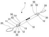
도 1과 도 2는 본 발명에서 바람직한 실시예로 제안하고 있는 치기공용 조각도의 전체 구성을 보여주는 것이고,
도 3은 본 발명에서 바람직한 실시예로 제안하고 있는 치기공용 조각도를 구성하는 광조사체의 진퇴를 통한 초점거리의 조절상태와, 통전 슬라이드부의 세부 구성 및 작용상태를 보여주는 것이고,
도 4는 본 발명에서 바람직한 실시예로 제안하고 있는 치기공용 조각도에 마련된 휘발성분의 흡기 여과상태를 보여주는 것이다.1 and 2 show the overall configuration of a dental engraving diagram proposed as a preferred embodiment in the present invention,
Figure 3 shows the state of adjustment of the focal length through advance and retreat of the light irradiator constituting the sculpture for dental work proposed as a preferred embodiment in the present invention, and the detailed configuration and operation of the energized slide part,
4 is a view showing the intake filtration state of the volatile component provided in the dental engraving diagram proposed as a preferred embodiment in the present invention.
이하, 첨부된 도면을 참조하여 본 발명에서 바람직한 실시예로 제안하고 있는 치기공용 조각도를 상세히 설명하기로 한다.Hereinafter, with reference to the accompanying drawings, it will be described in detail the sculpture for dental work proposed as a preferred embodiment in the present invention.
도 1과 도 2는 본 발명에서 바람직한 실시예로 제안하고 있는 치기공용 조각도의 전체 구성을 보여주는 것이고, 도 3은 본 발명에서 바람직한 실시예로 제안하고 있는 치기공용 조각도를 구성하는 광조사체의 진퇴를 통한 초점거리의 조절상태와, 통전 슬라이드부의 세부 구성 및 작용상태를 보여주는 것이고, 도 4는 본 발명에서 바람직한 실시예로 제안하고 있는 치기공용 조각도에 마련된 휘발성분의 흡기 여과상태를 보여주는 것이다.1 and 2 show the overall configuration of a dental engraving diagram proposed as a preferred embodiment in the present invention, and Figure 3 shows the advance and retreat of the light irradiator constituting the dental engraving diagram proposed as a preferred embodiment in the present invention. It shows the adjustment state of the focal length through, the detailed configuration and operation of the energized slide part, and FIG. 4 shows the intake filtration state of volatile components provided in the dental engraving diagram proposed as a preferred embodiment in the present invention.
본 발명에서 바람직한 실시예로 제안하고 있는 치기공용 조각도(1)는, 적어도 어느 하나 이상의 단부에 팁조립단(11)이 형성된 봉상체로 구성된 조각도 바디(10)와; 상기 조각도 바디(10)의 팁조립단(11)에 조립되는 조각도 팁(20)을 포함한다.The sculpture diagram (1) for dental work proposed as a preferred embodiment in the present invention is a sculpture diagram body (10) consisting of a rod-shaped body having a tip assembly end (11) formed at at least one or more ends; The sculpture also includes a
바람직하게는, 상기 조각도 바디(10)의 양단에는 각각 팁조립단(11)이 형성되어, 작업자는 상기 팁조립단(11)들을 통해 조각도 바디(10)의 양단에 각각 조각도 팁(20)을 조립하고, 조립된 조각도 팁(20)을 알콜램프를 통해 가열한 다음 가열된 조각도 팁(20)에 열간 용융되는 왁스를 적층하거나, 적층된 왁스를 열간 용융하여 형상을 교정하는 왁스작업을 실시한다.Preferably,
한편, 본 발명에서는 이러한 치기공용 조각도(1)를 구현함에 있어 상기 알콜램프를 통해 조각도 팁(20)을 가열하고, 가열된 조각도 팁(20)을 통해 요하는 왁스작업을 수행함에 있어, 상기 조각도 팁(20) 및 조각도 팁(20)에 의해 왁스작업되는 부위에 빛을 근접되게 조사하여 왁스 작업되는 부위의 음영발생의 억제와 조도를 상승함으로써, 안정된 가시도의 확보와 함께 왁스 작업에 따른 향상된 효율성과 정밀도를 갖도록 한다.On the other hand, in the present invention, in implementing the engraving diagram (1) for dental technicians, the
이를 위해, 본 실시예에서는 상기 조각도 팁(20)이 장착되는 조각도 바디(10)의 팁조립단(11)에, 왁스 작업부위로 빛을 발산하는 광조사체(30)를 배치한다.To this end, in the present embodiment, the
본 실시예에 따른 광조사체(30)는, 상기 팁조립단(11)에 동심구조로 설치되는 중공체로 구성되며, 실장된 LED 램프(31)의 점등을 통해 발산되는 빛을 조각도 팁(20)에 의한 왁스 작업부위에 조사하도록 한다.The
여기서, 상기 광조사체(30)는 전면에 투광 렌즈면(32a)이 형성된 중공의 렌즈 성형체(32)와, 상기 중공의 렌즈 성형체(32) 내에 실장되어 발광을 통해 생성된 빛을 투광 렌즈면(32a)을 통해 왁스작업 부위에 조사하는 하나 이상의 LED 램프(31)를 포함한다.Here, the
그리고, 상기 조각도 바디(10)에는 배터리(40)가 실장되어 상기 광조사체(30)의 LED 램프(31)는 상기 배터리로(40)부터 전류를 인가받아 점등하도록 구성된다.And, the
또한, 상기 광조사체(30)는 팁조립단(11)이 형성된 조각도 바디(10)의 양단에 진퇴구조로 설치되어, 작업자는 광조사체(30)를 진퇴하여 투광 렌즈면(32a)과 왁스 작업부위 사이의 초점거리의 조절을 통해 요하는 조사반경으로 왁스 작업부위에 빛을 조사하도록 한다.In addition, the
이를 위해, 본 실시예에서는 상기 팁조립단(11)의 외경에 광조사체(30)의 진퇴경로를 형성하는 가이드부(12)를 형성하여 상기 가이드부(12)에 광조사체(30)를 진퇴구조로 설치하는 한편, 상기 광조사체(30)의 후단과 조각도 바디(10)의 외경 사이에는 통전 슬라이드부(50)를 형성한다.To this end, in the present embodiment, a
상기 통전 슬라이드부(50)는, 조각도 바디(10)의 외경에 길이방향으로 형성되며 배터리(40)와 통전상태를 형성하는 한 쌍의 레일단자(51)와; 상기 광조사체(30)의 후단에 형성되어 실장된 LED 램프(31)와 통전상태를 형성하며 레일단자(51)와 접점을 형성한 접점단자(52)를 포함한다.The
바람직하게는, 상기 광조사체(30)의 후퇴거리는 레일단자(51)의 길이보다 상대적으로 길도록 구성되어, 상기 레일단자(51)의 후방에는 레일단자(51)와 접점단자(52)가 비접촉 상태를 형성하는 단선구간이 형성되도록 한다.Preferably, the retreat distance of the
따라서, 작업자가 광조사체(30)가 가이드부(12)를 따라 완전히 내측으로 후퇴하면 접점단자(52)와 레일단자(51) 사이의 통전상태는 단선되어서, 배터리(40)에 축전된 전류가 광조사체(30)의 LED 램프(31)에 인가되지 아니하여서 LED 램프(31)는 점멸된다.Therefore, when the operator fully retracts the
그리고, 상기 가이드부(12)를 따라 외측으로 진출하여 조사반경을 조절하는 광조사체(30)는 통전 슬라이드부(50)를 통해 배터리(40)에 축전된 전류를 안정되게 인가받아 점등된다.And, the
즉, 상기 통전 슬라이드부(50)는 배터리(40)와 LED 램프(31) 사이의 통전여부를 제어하는 스위칭 기능과, 가이드부(12)를 따라 진퇴하여 초점거리를 조절하는 광조사체(30)에 형성된 LED 램프(31)와 배터리(40) 사이의 안정적인 통전경로를 제공하는 긴요한 기능을 수행하는 구성요소이다.That is, the
이를 통해, 작업자는 광조사체(30)를 가이드부(12)를 따라 내외측으로 진퇴하여 광조사체(30)와 왁스 작업부위 사이의 거리를 조절함으로써 요하는 조사반경으로 왁스 작업부위에 빛을 조사하여 안정된 가시성이 확보하여서 왁스작업을 수행할 수 있고, 또 보관시에는 광조사체(30)를 가이드부(12)를 따라 내측으로 완전히 후퇴하여서 통전 슬라이드부(50)에 의한 배터리(40)와 LED 램프(31) 사이를 단선하게 된다.Through this, the operator moves the
이와 더불어, 본 실시예에서는 이러한 치기공용 조각도(1)를 구현함에 있어, 상기 조각도 바디(10)에, 가열된 조각도 팁(20)에서 휘발되는 휘발성분들을 강제 흡기하여 여과하는 구조를 마련하여서, 왁스의 가열에 의해 생성되는 휘발성분을 작업자가 호흡기를 통해 흡입하는 문제점과, 조각도 팁(20)의 가열에 의해 전도되는 열기에 의해 작업자에 의해 파지되는 조각도 바디(10)가 과열됨에 따른 화상 등의 안전사고를 예방한다.In addition, in this embodiment, in implementing the sculpture diagram (1) for dental work, a structure is provided to forcibly inhale and filter the volatile components volatilized from the heated fragmentation tip (20) in the sculpture diagram body (10), The problem of the worker inhaling the volatile components generated by heating the wax through the respiratory tract, and the burns caused by the overheating of the
이를 위해, 본 실시예에서는 상기 팁조립단(11)이 형성된 조각도 바디(10)의 단부에는 조각도 팁(20)의 가열에 의해 생성된 휘발성분들을 흡기하는 하나 이상의 흡기공(13)을 형성하고, 상기 조각도 바디(10) 내에는 각 흡기공(13)을 통해 가열된 조각도 팁(20)에서 휘발된 휘발성분을 흡기하여 순환 배출하는 흡기팬 유닛(14)과, 상기 흡기팬 유닛(14)을 통해 흡기된 휘발성분을 여과 처리하는 여과 처리부(15)를 부가한다.To this end, in this embodiment, one or
여기서, 상기 흡기팬 유닛(14)은 실장된 배터리(40)로부터 전류를 인가받아 조각도 팁(20)에서 휘발되는 휘발성분들을 강제 흡기하도록 구성된다.Here, the
그리고, 본 실시예에서는 상기 여과 처리부(15)에 저수된 처리액을 지속적으로 공급하는 저수포켓(16)을 형성하여, 상기 여과 처리부(15)는 필터층 내에 저수포켓(16)에 저수된 처리액을 삼투압을 통해 흡수하여 수처리막을 통해 여과 처리부(15)를 투과하는 휘발물질을 포집하도록 한다.And, in this embodiment, a
특히, 상기 저수포켓(16)은 작업자에 의해 파지되는 조각도 바디(10)의 파지부위 내부에 형성되어서, 저수포켓(16)의 외측에 형성된 파지부위는 저수포켓(16)에 내에 저수된 처리액을 통해서 냉각 및 단열이 도모된다.In particular, the
그리고, 상기 흡기공(13)을 통해 조각도 바디(10) 내로 흡기하여 조각도 바디(10)를 순환 배출하는 외부공기에 의해 조각도 바디(10)의 냉각이 도모되고, 결과적으로 알콜램프에 의해 팁조립단(11)에 조립된 조각도 팁(20)이 고온으로 가열되더라도 상기 조각도 바디(10)는 조각도 팁(20)을 통해 고온으로 가열되지 아니하고 순환 배출되는 외부공기에 의해 신속한 냉각이 도모된다.And, the cooling of the
따라서, 본 실시예에 따른 치기공용 조각도는 왁스 작업과정에 가열되는 조각도 팁(20)에서 전도되는 열기에 의해 조각도 바디(10)가 설정온도 이상으로 과열됨에 따른 화상 등의 안전상의 문제점이 해소될 수 있는 특이성을 갖는다.Therefore, in the dental engraving diagram according to this embodiment, safety problems such as burns caused by the
1. 치기공용 조각도
10. 조각도 바디 11. 팁조립단
12. 가이드부 13. 흡기공
14. 흡기팬 유닛 15. 여과 처리부
16. 저수포켓
20. 조각도 팁
30. 광조사체 31. LED 램프
32. 렌즈 성형체 32a. 투광 렌즈면
40. 배터리
50. 통전 슬라이드부 51. 레일단자
52. 접점단자1. Sculptor for dental work
10. Sculpting
12.
14.
16. Water pocket
20. Sculptor Tips
30.
32. Lens molded
40. Battery
50. Current energized
52. Contact terminal
Claims (3)
Translated fromKorean상기 조각도 바디의 팁조립단에 조립되는 조각도 팁; 및
상기 팁조립단에 설치되며, 발광된 LED 램프에서 발산되는 빛을 조각도 팁에 의해 왁스 작업되는 부위에 조사하여서, 왁스 작업부위의 가시성을 확보하는 광조사체를 포함하되,
상기 광조사체는 투광 렌즈면이 형성된 중공의 렌즈성형체와, 상기 중공의 렌즈성형체 내에 실장되어 발광을 통해 생성된 빛을 투광 렌즈면을 통해 왁스작업 부위에 조사하는 하나 이상의 LED 램프를 포함하고,
상기 팁조립단의 외경에는 가이드부가 형성되고, 상기 가이드부에는 광조사체를 진퇴구조로 설치하는 한편, 상기 광조사체의 후단과 조각도 바디의 외경 사이에는 통전 슬라이드부가 형성된 것을 특징으로 하는 치기공용 조각도.a sculptural body composed of a rod-shaped body having a tip assembly end formed at at least one end thereof;
a jigsaw tip assembled to the tip assembly end of the jigsaw body; and
A light irradiator installed at the tip assembly end and irradiating the light emitted from the light-emitting LED lamp to the area to be waxed by the sculpting tip to secure visibility of the area to be waxed,
The light irradiator includes a hollow lens molded body having a translucent lens surface formed therein, and one or more LED lamps mounted in the hollow lens molded body and irradiating light generated through light emission to the wax work site through the transmissive lens surface,
A guide part is formed on the outer diameter of the tip assembly end, and a light irradiator is installed in the guide part in a forward and backward structure, while an energized slide part is formed between the rear end of the light irradiator and the outer diameter of the engraving body.
상기 광조사체의 후퇴거리는 레일단자의 길이보다 상대적으로 길도록 구성되어, 상기 레일단자의 후방에는 레일단자와 접점단자가 비접촉 상태를 형성하는 단선구간을 형성하도록 구성된 것을 특징으로 하는 치기공용 조각도.
According to claim 1, wherein the energized slide portion is formed in the longitudinal direction on the outer diameter of the engraving body and a pair of rail terminals forming a energized state with the battery; A contact terminal formed at the rear end of the light irradiator to form a energized state with the mounted LED lamp and to form a contact point with the rail terminal,
The receding distance of the light irradiator is configured to be relatively longer than the length of the rail terminal, and the rail terminal and the contact terminal are configured to form a disconnection section forming a non-contact state at the rear of the rail terminal.
Priority Applications (1)
| Application Number | Priority Date | Filing Date | Title |
|---|---|---|---|
| KR1020210018229AKR102271494B1 (en) | 2021-02-09 | 2021-02-09 | Graver for dental technician |
Applications Claiming Priority (1)
| Application Number | Priority Date | Filing Date | Title |
|---|---|---|---|
| KR1020210018229AKR102271494B1 (en) | 2021-02-09 | 2021-02-09 | Graver for dental technician |
Publications (1)
| Publication Number | Publication Date |
|---|---|
| KR102271494B1true KR102271494B1 (en) | 2021-06-30 |
Family
ID=76602139
Family Applications (1)
| Application Number | Title | Priority Date | Filing Date |
|---|---|---|---|
| KR1020210018229AActiveKR102271494B1 (en) | 2021-02-09 | 2021-02-09 | Graver for dental technician |
Country Status (1)
| Country | Link |
|---|---|
| KR (1) | KR102271494B1 (en) |
Citations (7)
| Publication number | Priority date | Publication date | Assignee | Title |
|---|---|---|---|---|
| JPH0815001B2 (en)* | 1986-03-06 | 1996-02-14 | マグ・インストウルメント・インコ−ポレイテツド | flashlight |
| JPH1156185A (en)* | 1997-08-11 | 1999-03-02 | Nippon Kagaku Hakko Kk | Small-sized electric illuminant |
| US20080124671A1 (en)* | 2006-11-13 | 2008-05-29 | Bao Luu Nguyen | In situ powered hand dental instrument |
| KR20090037901A (en)* | 2006-07-31 | 2009-04-16 | 쓰리엠 이노베이티브 프로퍼티즈 컴파니 | LED light source with hollow condenser |
| KR20090009215U (en) | 2008-03-11 | 2009-09-16 | 강태현 | Dental spatula |
| KR101861557B1 (en)* | 2017-02-03 | 2018-05-28 | 대구보건대학교산학협력단 | Electric engraving apparatus for dental mechanic |
| KR102163009B1 (en) | 2019-02-25 | 2020-10-08 | 대구보건대학교산학협력단 | Spascula device for making impression models |
- 2021
- 2021-02-09KRKR1020210018229Apatent/KR102271494B1/enactiveActive
Patent Citations (7)
| Publication number | Priority date | Publication date | Assignee | Title |
|---|---|---|---|---|
| JPH0815001B2 (en)* | 1986-03-06 | 1996-02-14 | マグ・インストウルメント・インコ−ポレイテツド | flashlight |
| JPH1156185A (en)* | 1997-08-11 | 1999-03-02 | Nippon Kagaku Hakko Kk | Small-sized electric illuminant |
| KR20090037901A (en)* | 2006-07-31 | 2009-04-16 | 쓰리엠 이노베이티브 프로퍼티즈 컴파니 | LED light source with hollow condenser |
| US20080124671A1 (en)* | 2006-11-13 | 2008-05-29 | Bao Luu Nguyen | In situ powered hand dental instrument |
| KR20090009215U (en) | 2008-03-11 | 2009-09-16 | 강태현 | Dental spatula |
| KR101861557B1 (en)* | 2017-02-03 | 2018-05-28 | 대구보건대학교산학협력단 | Electric engraving apparatus for dental mechanic |
| KR102163009B1 (en) | 2019-02-25 | 2020-10-08 | 대구보건대학교산학협력단 | Spascula device for making impression models |
Similar Documents
| Publication | Publication Date | Title |
|---|---|---|
| US6482004B1 (en) | Light curing device and method for curing light-polymerizable dental material | |
| CN111065294B (en) | Hair drier | |
| KR101266681B1 (en) | Laser Hair Rmoval Device | |
| US4661070A (en) | Method for bleaching discolored teeth | |
| JP4880459B2 (en) | Electromagnetic radiation supply equipment | |
| US20210106384A1 (en) | Whitening and rejuvenating laser hair remover | |
| CN101588841A (en) | Optical body hair growth regulatng device | |
| KR102090484B1 (en) | Phototherapy brush for companion animals | |
| AU2002358983B2 (en) | Pulsed-light electric medical appliance for skin treatment | |
| JPH0344786B2 (en) | ||
| KR102271494B1 (en) | Graver for dental technician | |
| CN105147409A (en) | Optical fiber device for laser oral cavity treatment | |
| KR101157178B1 (en) | Portable apparatus for curing rhinitis | |
| CN120585168A (en) | UV curing device for nail art | |
| KR20040045000A (en) | Laser beam irradiation device | |
| JPS58501706A (en) | Optical fiber irradiation unit | |
| CN213491560U (en) | Rhinitis therapeutic instrument | |
| JP2009034235A (en) | Hair growth control light irradiation device | |
| CN210809305U (en) | Heating non-combustion device with infrared reflection light guide structure | |
| SG148159A1 (en) | Line light irradiation device | |
| JP3243643U (en) | Photo hair removal device | |
| KR102493201B1 (en) | Laser handpiece combined with resonator | |
| CN102551432A (en) | Anti-fog mirror for sterilizing shaving | |
| JP5174508B2 (en) | Hair growth control light irradiation device | |
| KR20160025497A (en) | Hair removal apparatus |
Legal Events
| Date | Code | Title | Description |
|---|---|---|---|
| PA0109 | Patent application | Patent event code:PA01091R01D Comment text:Patent Application Patent event date:20210209 | |
| PA0201 | Request for examination | ||
| PA0302 | Request for accelerated examination | Patent event date:20210209 Patent event code:PA03022R01D Comment text:Request for Accelerated Examination | |
| E902 | Notification of reason for refusal | ||
| PE0902 | Notice of grounds for rejection | Comment text:Notification of reason for refusal Patent event date:20210611 Patent event code:PE09021S01D | |
| E701 | Decision to grant or registration of patent right | ||
| PE0701 | Decision of registration | Patent event code:PE07011S01D Comment text:Decision to Grant Registration Patent event date:20210621 | |
| GRNT | Written decision to grant | ||
| PR0701 | Registration of establishment | Comment text:Registration of Establishment Patent event date:20210625 Patent event code:PR07011E01D | |
| PR1002 | Payment of registration fee | Payment date:20210625 End annual number:3 Start annual number:1 | |
| PG1601 | Publication of registration | ||
| PR1001 | Payment of annual fee | Payment date:20240415 Start annual number:4 End annual number:4 | |
| PR1001 | Payment of annual fee | Payment date:20250325 Start annual number:5 End annual number:5 |